
Interview Basic IT
29
1 Diffrenece between switch and , router and modem Operator overloading, binary operator overloading Testing SMPS Command to find system name, MAC address etc : nbtstat a <IP> Steps: Assembling a PC RISC vs CISC The simplest way to examine the advantages a nd disadvantages of RISC architecture is by contrasting it with it's predecessor: CISC (Complex Instruction Set Computers) architecture. Multiplying Two Numbers in Memory On the right is a diagram representing the storage scheme for a generic computer. The main memory is divided into locations numbered from (row) 1: (column) 1 to (row) 6: (column) 4. The execution unit is responsible for carrying out all computations. However, the execution unit c an only operate on data that has been loaded into one of the six registers (A, B, C, D, E, or F). Let's say we want to find the product of two numbers - one stored in location 2:3 and another stored in location 5:2 - and then store the product back in the location 2:3. The CISC Approach The primary goal of CISC architecture is to complete a ta sk in as few lines of assembly as possible. This is achieved by building processor hardware that is capable of understanding and executing a series of operations. For this particular task, a CISC processor would come prepared with a specific instruction (we'll call it "MULT"). When executed, this instruction loads the two values into separate registers, multiplies the operands in the execution unit, and then stores the product in the appropriate register. Thus, the entire task of multiplying two numbers can be c ompleted with one instruction: MULT 2:3, 5:2 MULT is what is known as a "complex instruction ." It operates directly on the computer's memory banks and does not require the programmer to explicitly call any loading or storing functions. It closely resembles a command in a higher level language. For instance, if we let " a" represent the value of 2:3 and " b" represent the value of 5:2, then this command is identical to the C statement "a = a * b." One of the primary advantages of this system is that the compiler has to do very little work to translate a high-level language statement into assembly. Because the length of the code is relatively short, very little RAM is required to store i nstructions. The emphasis is put on building complex instructions directly into the hardware. The RISC Approach RISC processors only use simple instruction s that ca n be executed within one clock cycle. Thus, the " MULT" command described above could be divided into three separate commands: "LOAD," which moves data from
-
Upload
aravind-narayan -
Category
Documents
-
view
219 -
download
0
Transcript of Interview Basic IT

8/6/2019 Interview Basic IT
http://slidepdf.com/reader/full/interview-basic-it 1/29
1
Diffrenece between switch and , router and modem
Operator overloading, binary operator overloading
Testing SMPS
Command to find system name, MAC address etc : nbtstat a <IP>
Steps: Assembling a PC
RISC vs CISC
The simplest way to examine the advantages and disadvantages of RISC architecture is by contrasting it withit's predecessor: CISC (Complex Instruction Set Computers) architecture.
Multiplying Two Numbers in Memory On the right is a diagram representing the storage schemefor a generic computer. The main memory is divided intolocations numbered from (row) 1: (column) 1 to (row) 6:(column) 4. The execution unit is responsible for carryingout all computations. However, the execution unit can only
operate on data that has been loaded into one of the sixregisters (A, B, C, D, E, or F). Let's say we want to find theproduct of two numbers - one stored in location 2:3 andanother stored in location 5:2 - and then store the product back in the location 2:3.
The CISC Approach The primary goal of CISC architecture is to complete a task in as few lines of assembly as possible. This is achieved bybuilding processor hardware that is capable of understanding and executing a series of operations. For thisparticular task, a CISC processor would come preparedwith a specific instruction (we'll call it "MULT"). Whenexecuted, this instruction loads the two values intoseparate registers, multiplies the operands in the executionunit, and then stores the product in the appropriateregister. Thus, the entire task of multiplying two numberscan be completed with one instruction:
MULT 2:3, 5:2
MULT is what is known as a "complex instruction." It operates directly on the computer's memory banks anddoes not require the programmer to explicitly call any loading or storing functions. It closely resembles acommand in a higher level language. For instance, if we let "a" represent the value of 2:3 and "b" represent the value of 5:2, then this command is identical to the C statement "a = a * b."
One of the primary advantages of this system is that the compiler has to do very little work to translate ahigh-level language statement into assembly. Because the length of the code is relatively short, very little RAMis required to store instructions. The emphasis is put on building complex instructions directly into thehardware.
TheRISC ApproachRISC processors only use simple instructions that can be executed within one clock cycle. Thus, the "MULT"command described above could be divided into three separate commands: "LOAD," which moves data from
8/6/2019 Interview Basic IT
http://slidepdf.com/reader/full/interview-basic-it 2/29
2
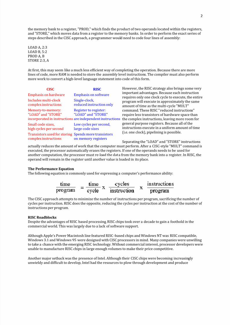
the memory bank to a register, "PROD," which finds the product of two operands located within the registers,and "STORE," which moves data from a register to the memory banks. In order to perform the exact series of steps described in the CISC approach, a programmer would need to code four lines of assembly:
LOAD A, 2:3LOAD B, 5:2
PROD A, BSTORE 2:3, A
At first, this may seem like a much less efficient way of completing the operation. Because there are morelines of code, more RAM is needed to store the assembly level instructions. The compiler must also performmore work to convert a high-level language statement into code of this form.
However, the RISC strategy also brings some veryimportant advantages. Because each instructionrequires only one clock cycle to execute, the entireprogram will execute in approximately the sameamount of time as the multi-cycle "MULT"command. These RISC "reduced instructions"
require less transistors of hardware space thanthe complex instructions, leaving more room forgeneral purpose registers. Because all of theinstructions execute in a uniform amount of time(i.e. one clock), pipelining is possible.
Separating the "LOAD" and "STORE" instructionsactually reduces the amount of work that the computer must perform. After a CISC-style "MULT" command isexecuted, the processor automatically erases the registers. If one of the operands needs to be used foranother computation, the processor must re-load the data from the memory bank into a register. In RISC, theoperand will remain in the register until another value is loaded in its place.
T
he Performance Equation
The following equation is commonly used for expressing a computer's performance ability:
The CISC approach attempts to minimize the number of instructions per program, sacrificing the number of cycles per instruction. RISC does the opposite, reducing the cycles per instruction at the cost of the number of instructions per program.
RISC RoadblocksDespite the advantages of RISC based processing, RISC chips took over a decade to gain a foothold in the
commercial world. This was largely due to a lack of software support.
Although Apple's Power Macintosh line featured RISC-based chips and Windows NT was RISC compatible,Windows 3.1 and Windows 95 were designed with CISC processors in mind. Many companies were unwillingto take a chance with the emerging RISC technology. Without commercial interest, processor developers wereunable to manufacture RISC chips in large enough volumes to make their price competitive.
Another major setback was the presence of Intel. Although their CISC chips were becoming increasinglyunwieldy and difficult to develop, Intel had the resources to plow through development and produce
CISC RISC
Emphasis on hardware Emphasis on software
Includes multi-clock complex instructions
Single-clock,reduced instruction only
Memory-to-memory:
"LOAD" and "STORE"incorporated in instructions
Register to register:
"LOAD" and "STORE"are independent instructions
Small code sizes,high cycles per second
Low cycles per second,large code sizes
Transistors used for storingcomplex instructions
Spends more transistorson memory registers

8/6/2019 Interview Basic IT
http://slidepdf.com/reader/full/interview-basic-it 3/29
3
powerful processors. Although RISC chips might surpass Intel's efforts in specific areas, the differences werenot great enough to persuade buyers to change technologies.
TheOverall RISC Advantage Today, the Intel x86 is arguable the only chip which retains CISC architecture. This is primarily due toadvancements in other areas of computer technology. The price of RAM has decreased dramatically. In 1977,
1MB of DRAM cost about $5,000. By 1994, the same amount of memory cost only $6 (when adjusted forinflation). Compiler technology has also become more sophisticated, so that the RISC use of RAM andemphasis on software has become ideal.
DMA And advantages
North bridge and South Bridge.
DNS and DHCP
Java Exception handing
Exception Handling Techniques in Java
(Page 1 of 4 )
All right, let's begin explaining what exceptions are. Just as in other programming languages, this applies to Java as well:exceptions are those errors that occur during runtime. These aren't real errors, because they are exceptions. One might call them exceptional events that can and should be handled to continue program execution. So there's "something" onehas to do about them.
One of the most remarkable examples of exceptional cases and conditions is when, during program execution, the timecomes for a division by zero. This cannot be done and, therefore, Java throws an exception, specifically theArithmeticException. From the Java programmer's point of view, exceptions are objects. Throwing exceptions is akin tothrowing objects. But here's the drill: not every object can be thrown.
In order to fully understand throwable exceptions, some parts of the entire class hierarchy should be presented. There isone main class called Throwable. This class has two sub-classes: Exception and Error. An exception object must bedescended from a class that is Throwable, meaning it must be an object instance of either an Exception sub-class or Errorsub-class. These can both be found in the java.lang package.
Exception handling is the technique of catching the exceptions that might be thrown some time in the future duringruntime. Java offers robust exception handling solutions with the try-catch-finally construct. On other hand, you can work with already-declared exceptions, such as the ArithmeticException, NullPointerException, and others. Other classes
extend the Exception class-e.g., the IOException subclass from java.io.
Furthermore, we should also note that exceptions are of two kinds: unchecked and checked. Unchecked exceptions aretechnically RuntimeExceptions (or its subclasses). These don't need to be declared in your throws clauses, and catchingthem is optional, but many don't bother-they occur without the knowledge of programmers, who may not even know that those are "catchable." Most of the time, these are logic programming errors such as NullPointerException or
ArrayIndexOutOfBounds.
Meanwhile, checked exceptions technically force the programmer to handle and manage them, meaning catch and coverthem individually. These are derived from the Exceptions class and its subclasses, excluding the RuntimeExceptions as wediscussed in the paragraph above (those are unchecked!). Checked exceptions require exception handling because theymight cause program termination.
Now that we've learned the basic theory, let's fire up our IDE, and start coding!
On the previous page we mentioned that exception handling either deals with the exception in the code snippet where it occurs with the try/catch block, or throws the exception back to the runtime engine, which on its end will search for the
8/6/2019 Interview Basic IT
http://slidepdf.com/reader/full/interview-basic-it 4/29
4
exception handling routine that is the closest to the place where the exception occurred. It searches within the call stack
that contains the sequence of method calls.
Generally, exceptions can happen due to either having an abnormal event that leads to an exceptional case, or anothermethod has thrown the exception and now it's time to deal with it, or in the case of an asynchronous exception (whichhappens only when multiple threads are used and they aren't synchronized appropriately). Now we are going to cover the
basics of exception handling: how to "catch" and deal with them.
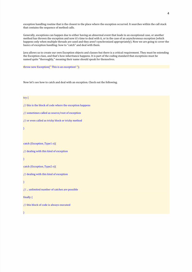
Java allows us to create our own Exception objects and classes-but there is a critical requirement. They must be extendingthe Exception class, and that's how inheritance happens. It is part of the coding standard that exceptions must be
named quite "thoroughly," meaning their name should speak for themselves.
throw new Exception(" This is an exception! ");
Now let's see how to catch and deal with an exception. Check out the following.
try {
// this is the block of code where the exception happens
// sometimes called as source/root of exception
// or even called as tricky block or tricky method
}
catch (Exception_Type1 e){
// dealing with this kind of exception
}
catch (Exception_Type2 e){
// dealing with this kind of exception
}
// ... unlimited number of catches are possible
finally {
// this block of code is always executed
}
8/6/2019 Interview Basic IT
http://slidepdf.com/reader/full/interview-basic-it 5/29
5
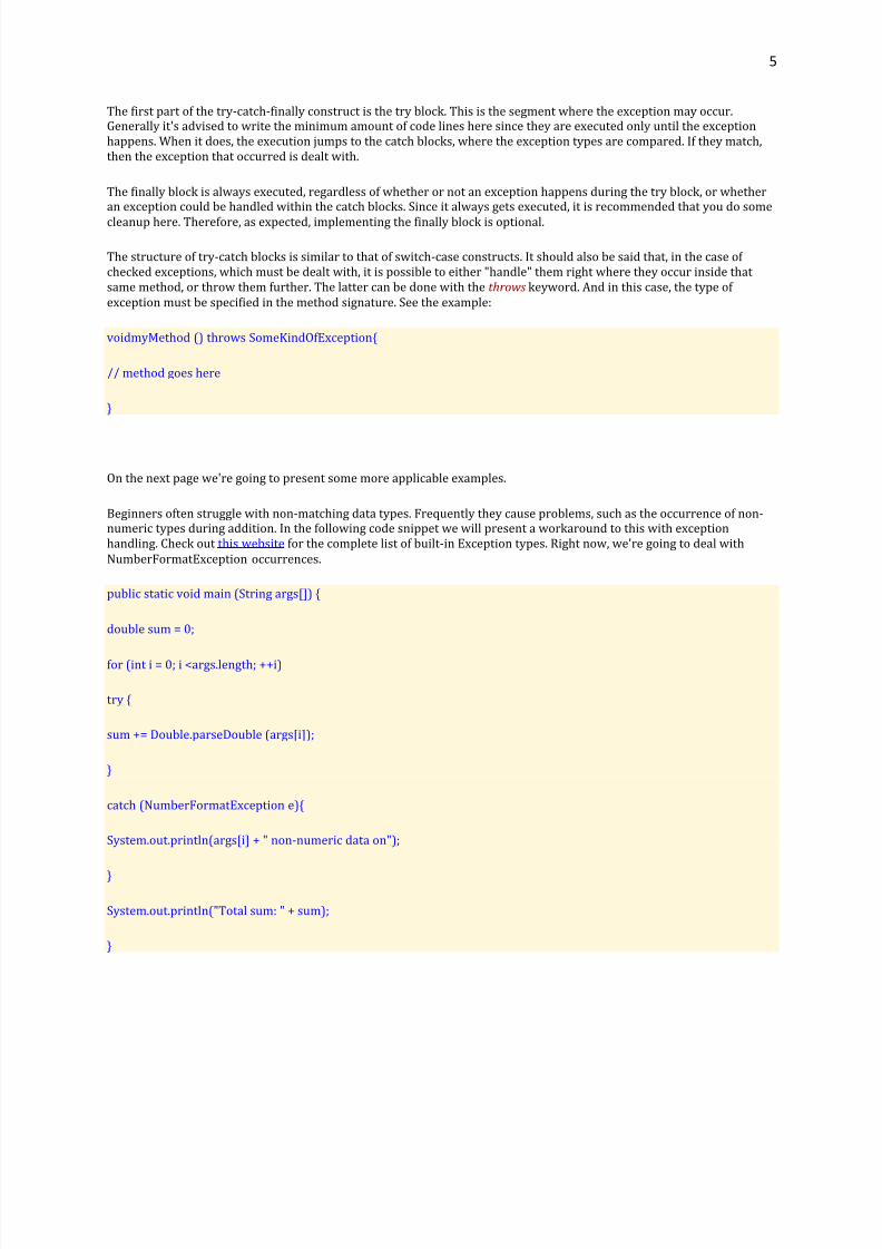
The first part of the try-catch-finally construct is the try block. This is the segment where the exception may occur.Generally it's advised to write the minimum amount of code lines here since they are executed only until the exceptionhappens. When it does, the execution jumps to the catch blocks, where the exception types are compared. If they match,then the exception that occurred is dealt with.
The finally block is always executed, regardless of whether or not an exception happens during the try block, or whetheran exception could be handled within the catch blocks. Since it always gets executed, it is recommended that you do some
cleanup here. Therefore, as expected, implementing the finally block is optional.
The structure of try-catch blocks is similar to that of switch-case constructs. It should also be said that, in the case of checked exceptions, which must be dealt with, it is possible to either "handle" them right where they occur inside that same method, or throw them further. The latter can be done with the throws keyword. And in this case, the type of exception must be specified in the method signature. See the example:
voidmyMethod () throws SomeKindOfException{
// method goes here
}
On the next page we're going to present some more applicable examples.
Beginners often struggle with non-matching data types. Frequently they cause problems, such as the occurrence of non-numeric types during addition. In the following code snippet we will present a workaround to this with exceptionhandling. Check out this website for the complete list of built-in Exception types. Right now, we're going to deal with
NumberFormatException occurrences.
public static void main (String args[]) {
double sum = 0;
for (int i = 0; i <args.length; ++i)
try {
sum += Double.parseDouble (args[i]);
}
catch (NumberFormatException e){
System.out.println(args[i] + " non-numeric data on");
}
System.out.println("Total sum: " + sum);
}

8/6/2019 Interview Basic IT
http://slidepdf.com/reader/full/interview-basic-it 6/29
6
As you can see, it works with command line arguments, and once a non-numeric argument is reached, it is just written tothe standard system out, specifying what's wrong. But the program goes on, since the try block is within a for loop.Otherwise, without proper exception handling, the program would be terminated. This way the sum is still calculated andprinted out at the end.
Let's present another example. Here we are going to build our own exception class that extends the parent Exceptionclass. The application will simulate the way a stack mechanism works with exception handling, throwing and dealing with
exceptions such as Stack is full (and you want to add more elements into the stack) or Stack is empty (and you want topop elements from the stack). Check it out.
public class StackException extends Exception {
publicStackException (String text) {
super (text);
}
}
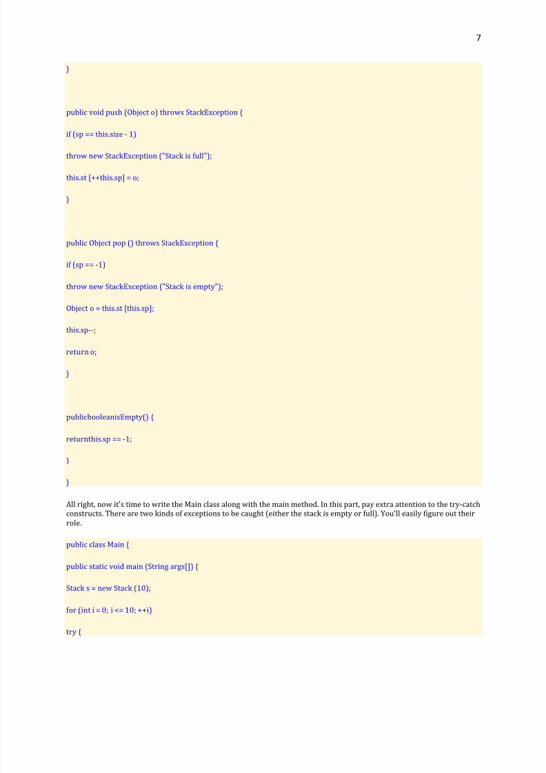
Now let's create the Stack class itself. Pay attention to the push and pop methods. They are throwing the StackExceptiontype of exception, and this is introduced within the method signature. Moreover, there's an if condition, and the exceptionis thrown if it's satisfied. Otherwise, everything just happens smoothly.
public class Stack {
private final int SIZE = 100;
private Object st[];
privateint size;
privateintsp;
public Stack (int size) {
if (size < MAXSIZE)
this.size = size;
else
this.size = MAXSIZE;
this.st = new Object [size];
this.sp = -1;
8/6/2019 Interview Basic IT
http://slidepdf.com/reader/full/interview-basic-it 7/29
7
}
public void push (Object o) throws StackException {
if (sp == this.size - 1)
throw new StackException ("Stack is full");
this.st [++this.sp] = o;
}
public Object pop () throws StackException {
if (sp == -1)
throw new StackException ("Stack is empty");
Object o = this.st [this.sp];
this.sp--;
return o;
}
publicbooleanisEmpty() {
returnthis.sp == -1;
}
}
All right, now it's time to write the Main class along with the main method. In this part, pay extra attention to the try-catchconstructs. There are two kinds of exceptions to be caught (either the stack is empty or full). You'll easily figure out theirrole.
public class Main {
public static void main (String args[]) {
Stack s = new Stack (10);
for (int i = 0; i <= 10; ++i)
try {

8/6/2019 Interview Basic IT
http://slidepdf.com/reader/full/interview-basic-it 8/29
8
s.push (new Integer(i));
}
catch (StackException e) {
System.out.println (e);
}
while (! s.isEmpty() ) {
try {
System.out.println( (Integer)(s.pop()) );
}
catch (StackException e) {
System.out.println(e);
}
}
}
}
Of course, here's the attached output as well. As you can see, the first line that is printed out is the exception, since we'replanning to fill the stack with 11 elements (consider: the for loop begins from 0 and goes up to 10 but also includes that value, this is a total of 11 elements), thus, the exception is thrown. Then it is also dealt with. The other exception doesn't
get thrown, since the while loop goes until isEmpty is false.
Stack is full
9
8
7
6
5
4
8/6/2019 Interview Basic IT
http://slidepdf.com/reader/full/interview-basic-it 9/29
9
3
2
1
0
Play around with the above code for a little while. Try to pop another element. And don't get surprised if the exception isthrown but also dealt with right away. That is the real power of exception handling, as you can see. So that's it for now.
Embedded SQL
The first technique for sending SQL statements to the DBMS is embedded SQL. Because SQL does not usevariables and control-of-flow statements, it is often used as a database sublanguage that can be added to aprogram written in a conventional programming language, such as C or COBOL. This is a central idea of embedded SQL: placing SQL statements in a program written in a host programming language. Briefly, thefollowing techniques are used to embed SQL statements in a host language:
y Embedded SQL statements are processed by a special SQL precompiler. All SQL statements begin withan introducer and end with a terminator, both of which flag the SQL statement for the precompiler.The introducer and terminator vary with the host language. For example, the introducer is "EXEC SQL"in C and "&SQL(" in MUMPS, and the terminator is a semicolon (;) in C and a right parenthesis inMUMPS.
y Variables from the application program, called host variables, can be used in embedded SQLstatements wherever constants are allowed. These can be used on input to tailor an SQL statement to a
particular situation and on output to receive the results of a query.y Queries that return a single row of data are handled with a singleton SELECT statement; this statement
specifies both the query and the host variables in which to return data.
y Queries that return multiple rows of data are handled with cursors. A cursor keeps track of the current row within a result set. The DECLARE CURSOR statement defines the query, the OPEN statement begins the query processing, the FETCH statement retrieves successive rows of data, and the CLOSEstatement ends query processing.
y While a cursor is open, positioned update and positioned delete statements can be used to update ordelete the row currently selected by the cursor.
The following code is a simple embedded SQL program, written in C. The program illustrates many, but not all, of the embedded SQL techniques. The program prompts the user for an order number, retrieves thecustomer number, salesperson, and status of the order, and displays the retrieved information on the screen.
int main() {EXEC SQL INCLUDE SQLCA;EXEC SQL BEGIN DECLARE SECTION;
intOrderID; /* Employee ID (from user) */intCustID; /* Retrieved customer ID */charSalesPerson[10] /* Retrieved salesperson name */char Status[6] /* Retrieved order status */
EXEC SQL END DECLARE SECTION;

8/6/2019 Interview Basic IT
http://slidepdf.com/reader/full/interview-basic-it 10/29
10
/* Set up error processing */EXEC SQL WHENEVER SQLERROR GOTO query_error;EXEC SQL WHENEVER NOT FOUND GOTO bad_number;
/* Prompt the user for order number */
printf ("Enter order number: ");scanf_s("%d", &OrderID);
/* Execute the SQL query */EXEC SQL SELECT CustID, SalesPerson, Status
FROM OrdersWHERE OrderID= :OrderID
INTO :CustID, :SalesPerson, :Status;
/* Display the results */printf ("Customer number: %d\n", CustID);printf ("Salesperson: %s\n", SalesPerson);printf ("Status: %s\n", Status);
exit();
query_error:printf ("SQL error: %ld\n", sqlca->sqlcode);exit();
bad_number:printf ("Invalid order number.\n");exit();}
Note the following about this program:
y Host Variables The host variables are declared in a section enclosed by the BEGIN DECL ARESECTION and END DECL ARE SECTION keywords. Each host variable name is prefixed by a colon (:)when it appears in an embedded SQL statement. The colon allows the precompiler to distinguishbetween host variables and database objects, such as tables and columns, that have the same name.
y DataTypes The data types supported by a DBMS and a host language can be quite different. Thisaffects host variables because they play a dual role. On one hand, host variables are program variables,declared and manipulated by host language statements. On the other hand, they are used in embeddedSQL statements to retrieve database data. If there is no host language type that corresponds to a DBMSdata type, the DBMS automatically converts the data. However, because each DBMS has its own rulesand idiosyncrasies associated with the conversion process, the host variable types must be chosencarefully.
y Error Handling The DBMS reports run-time errors to the applications program through an SQLCommunications Area, or SQLCA. In the preceding code example, the first embedded SQL statement is
INCLUDE SQLCA. This tells the precompiler to include the SQLCA structure in the program. This isrequired whenever the program will process errors returned by the DBMS. The WHENEVER...GOTOstatement tells the precompiler to generate error-handling code that branches to a specific label whenan error occurs.
y Singleton SELECTThe statement used to return the data is a singleton SELECT statement; that is, it returns only a single row of data. Therefore, the code example does not declare or use cursors.

8/6/2019 Interview Basic IT
http://slidepdf.com/reader/full/interview-basic-it 11/29
11
Distributed database (RDBMS)
A distributed database is not stored in its entirety at a single physical location. Instead, it is spread across a
network of computers that are geographically dispersed and connected via communications links. A distributed database allows faster local queries and can reduce network traffic. With these benefits comes the
issue of maintaining data integrity. A key objective for a distributed system is that it looks like a centralized system to the user. The user should not
need to know where a piece of data is stored physically. Forms of Distributed Data There are five categories of distributed data: · replicated data, · horizontally fragmented data, · vertically fragmented data, · reorganized data, · separate-schema data.
Replicated Data Replicated data means that copies of the same data are maintained in more than one location. Data may be
replicated across multiple machines to avoid transmitting data between systems. Replicas can be read only or writable. Read only replicas have changes made to the original and then
propagated outwards to the replicas. Writable replicas propagate changes back to the original using either a
"write through" or a "write back" strategy. Write through implies a synchronous connection and a "real-time"
update to the original. The write back strategy allows changes to be propagated when it is most appropriate
(i.e., a "store-and-forward" or an asynchronous concept). Consider the timeliness of the transactions against the data. How up-to-date or current does the data/replicas
have to be? The biggest concern with replicated data is how to handle "collisions." Refer to Issues to Consider
When Distributing Data for further information on handling collisions. Replicated data can simplify disaster
recovery because data can be restored to the failed site from one of the replicated copies. Replicated data is
most effective when data is not updated frequently. This tool suite maintains replicated databases for each
installation. Horizontally Fragmented Data Horizontally fragmented data means that data is distributed across different sites based on one or more primary
keys. This type of data distribution is typical where, for example, branch offices in an organization deal mostly
with a set of local customers and the related customer data need not be accessed by other branch offices. Vertically Fragmented Data
Vertically fragmented data is data that has been split by columns across multiple systems. The primary key isreplicated at each site. For example, a district office may maintain client information such as name and address
keyed on client number while head office maintains client account balance and credit information, also keyed on
the same client number. Reorganized Data Reorganized data is data that has been derived, summarized, or otherwise manipulated in some way. This type
of data organization is common where decision-support processing is performed. There may be some instances
where the on-line transaction processing (OLTP) and decision-support database management systems are
8/6/2019 Interview Basic IT
http://slidepdf.com/reader/full/interview-basic-it 12/29
12
different. Decision-support typically requires better query optimization and ad hoc SQL support than does
OLTP. OLTP usually requires optimization for high-volume transaction processing. Separate-Schema Data Separate-schema data maintains separate databases and application programs for different systems. For
example, one system may manage inventory and one may handle customer orders. There may be a certain
amount of duplication with separate-schema data. Comparison of Distributed DBMSs and Replicated Databases One of the requirements to maintain data integrity using a distributed database management system (DBMS) is
the two-phase commit. A two-phase commit first requires that the data to be updated is locked on all nodes on
the network that maintain the data. Only when the originating node receives confirmation from all other nodes
that the data is updated can the originating node commit the updates to the database and release the data. A
failure on the network at any point during the commit transaction may cause the entire transaction to fail. The
two-phase commit approach to updating data becomes less attractive when the network consists of several
nodes. The more nodes the more potential for failed transactions. A better alternative to a distributed DBMS for many applications is data replication. Replication does not
require a tightly coupled two-phase commit. Instead, replication allows local copies of the data to be updatedand uses behind-the-scenes updating of the same data across the network. Replication technologies rely on
asynchronous communications to keep data synchronized. Data updates made at one node are relayed to other
nodes at set time intervals. The time interval for the updates depends on the needs of the user. For example,
asynchronous updates may be communicated immediately, every hour, or once a day. There are many approaches to replication ranging from decision-support replication (DSS-R) technologies that
maintain read-only copies of data locally to transaction-processing replication (TP-R) technologies that offer
near real time data updates designed to replace distributed DBMS technologies. DSS-R approaches are suited for
applications that require historical data such as decision-support applications or backup systems that can be
used as standby databases in the event that the main database connection is lost. TP-R approaches are more
suited for applications that require current, not historical, data but do not require complete data
synchronization, such as a reservation system that allows for overbooking.
The most appropriate approach to data distribution depends on your application. The two-phase commit is stillthe best approach when the most current data is required, such as for an automated teller machine.

8/6/2019 Interview Basic IT
http://slidepdf.com/reader/full/interview-basic-it 13/29
13
8/6/2019 Interview Basic IT
http://slidepdf.com/reader/full/interview-basic-it 14/29
14
Garbage Collection (Data and File Structure)
In computer science, garbage collection (GC) is a form of automatic memory management . It is a special case
of resource management , in which the limited resource being managed is memory. The garbage collector , or
just collector , attempts to reclaim garbage, or memory occupied byobjects that are no longer in use by
the program. Garbage collection was invented by John McCarthy around 1959 to solve problems in Lisp.[1][2]
Garbage collection is often portrayed as the opposite of manual memory management , which requires the
programmer to specify which objects to deallocate and return to the memory system. However, many
systems use a combination of the two approaches, and other techniques such as stack allocation and region
inference can carve off parts of the problem. There is an ambiguity of terms, as theory often uses the
terms manual garbage collection and automatic garbage collection rather than manual memory
management and garbage collection , and does not restrict garbage collection to memory management, rather
considering that any logical or physical resource may be garbage collected.
Garbage collection does not traditionally manage limited resources other than memory that typical programs
use, such as network sockets, database handles, user interaction windows, and file and device descriptors.
Methods used to manage such resources, particularly destructors, may suffice as well to manage memory,
leaving no need for GC. Some GC systems allow such other resources to be associated with a region of
memory that, when collected, causes the other resource to be reclaimed; this is called finalization.
Finalization may introduce complications limiting its usability, such as intolerable latency between disuse
and reclaim of especially limited resources, or a lack of control over which thread performs the work of
reclaiming.
Garbage Collection
by Bill Venners
The Java virtual machine's heap stores all objects created by a running Java application. Objects are created bythe new, newarray, anewarray, and multianewarray instructions, but never freed explicitly by the code. Garbagecollection is the process of automatically freeing objects that are no longer referenced by the program.
This chapter does not describe an official Java garbage-collected heap, because none exists. As mentioned in earlierchapters, the Java virtual machine specification does not require any particular garbage collection technique. It doesn't even require garbage collection at all. But until infinite memory is invented, most Java virtual machine implementationswill likely come with garbage-collected heaps. This chapter describes various garbage collection techniques and explains
how garbage collection works in Java virtual machines.
Accompanying this chapter on the CD-ROM is an applet that interactively illustrates the material presented in the chapter.The applet, named Heap of Fish, simulates a garbage-collected heap in a Java virtual machine. The simulation--whichdemonstrates a compacting, mark-and-sweep collector--allows you to interact with the heap as if you were a Javaprogram: you can allocate objects and assign references to variables. The simulation also allows you to interact with theheap as if you were the Java virtual machine: you can drive the processes of garbage collection and heap compaction. At
the end of this chapter, you will find a description of this applet and instructions on how to use it.

8/6/2019 Interview Basic IT
http://slidepdf.com/reader/full/interview-basic-it 15/29
15
Why Garbage Collection?
The name "garbage collection" implies that objects no longer needed by the program are "garbage" and can be thrownaway. A more accurate and up-to-date metaphor might be "memory recycling." When an object is no longer referenced bythe program, the heap space it occupies can be recycled so that the space is made available for subsequent new objects.The garbage collector must somehow determine which objects are no longer referenced by the program and make
available the heap space occupied by such unreferenced objects. In the process of freeing unreferenced objects, thegarbage collector must run any finalizers of objects being freed.
In addition to freeing unreferenced objects, a garbage collector may also combat heap fragmentation. Heap fragmentationoccurs through the course of normal program execution. New objects are allocated, and unreferenced objects are freedsuch that free portions of heap memory are left in between portions occupied by live objects. Requests to allocate newobjects may have to be filled by extending the size of the heap even though there is enough total unused space in theexisting heap. This will happen if there is not enough contiguous free heap space available into which the new object willfit. On a virtual memory system, the extra paging (or swapping) required to service an ever growing heap can degrade theperformance of the executing program. On an embedded system with low memory, fragmentation could cause the virtual
machine to "run out of memory" unnecessarily.
Garbage collection relieves you from the burden of freeing allocated memory. Knowing when to explicitly free allocatedmemory can be very tricky. Giving this job to the Java virtual machine has several advantages. First, it can make you more
productive. When programming in non-garbage-collected languages you can spend many late hours (or days or weeks)chasing down an elusive memory problem. When programming in Java you can use that time more advantageously bygetting ahead of schedule or simply going home to have a life.
A second advantage of garbage collection is that it helps ensure program integrity. Garbage collection is an important part of Java's security strategy. Java programmers are unable to accidentally (or purposely) crash the Java virtual machine byincorrectly freeing memory.
A potential disadvantage of a garbage-collected heap is that it adds an overhead that can affect program performance. TheJava virtual machine has to keep track of which objects are being referenced by the executing program, and finalize andfree unreferenced objects on the fly. This activity will likely require more CPU time than would have been required if theprogram explicitly freed unnecessary memory. In addition, programmers in a garbage-collected environment have lesscontrol over the scheduling of CPU time devoted to freeing objects that are no longer needed.
Raster and Vector Animation
Computer animation has become in recent years one o f the most popular film genres. There are two main types of computer animation:
vector-based and raster-based. Vector animation is based on simple geometric shapes, while raster-based animation is created using
more detailed images similar to photos or paintings. There are advantages and disadvantages to using raster-based animation.
Definition
o Raster based animation frames (and all raster images for that matter) are made up of individual pixels. These pixels
each contain information about the color and brightness of t hat particular spot on the image. This is so mewhat
similar to the concept of pointillism in painting, with the su m of the points making u p the totality of the picture or
frame.
Useso Raster animation is used for depicting realistic representations of people, animals or places, rather than the more
stylized, anime-style animation you might get with vector graphics. Raster animation is also use to create animation
for logos and banners based on photos or drawings.
Difficulties
o One of the problems involved with creating raster-based animations on a computer is the enormous amount o f
computer power that is often involved in creating them. For example, a single frame of animation that is 400x300
pixels in size will have have a total of 120,000 pixels. Each of these pixels will have (depending on t he color scheme
being used) eight to 48 bits, meaning each frame migh t use as many as 5 .76 million bits. This means that an
animated 14-frame-per-second video of 20 minutes would have 2.02 trillion bits of information. Most films are
larger than this with a higher frame rate.

8/6/2019 Interview Basic IT
http://slidepdf.com/reader/full/interview-basic-it 16/29
16
Limitations
o A major difficulty with working with raster-based animation or images is that they are not infinitely enlargeable.
This means that if you create a raster based anim ation at a certain size (400x300, for example), you will not be able
to enlarge it to any significant extent without loss of reso lution in the images. Vector graphics do not have this
problem.
Sub-types
o There are two main sub-types of co mputer raster: drawn raster animation, which is created in programs like
Photoshop or Painter, using the various painting and drawing tools. This typ e is often used for television or web
page animations. The other type is created using rendered images from co mputer-generated imagery (CGI)
programs like Maya or Cinema 4D. This is the ty pe that is most often seen in movies.
Advantages of Raster Animation
y Compression Flash provides an easy way to change the files compression (Right-click the ras ter file, select Properties)
y Easier on the CPU Compared to vector animation, raster animation takes less CPU time
y Assurance You know exactly what your raster image will look like in Flash, in the case of vector animation, youre handing that
responsibility over to the program
y Smooth At the expense of CPU time, you can Allow S moothing on files that w ill be lightly resized (Right-click the raster file, select
Properties)
y Faster Effects When filters or alpha is applied, a raster graphic will perform faster then a vector graphic
Advantages of Vector Animation
y Compression Flash provides an easy way to smooth otherwise co mplex curbs to help shave uneeded detail (Select the sha pe, Modify
-> Shape -> Optimize)
y Scalability Vector graphics can be scaled or blown-up if needed in your animation. Raster files leave much to be desired
y Smooth Vector graphics, when lightly resized, will appear smoother then raster animation
y File size Since vectors are made up of mathematics instead of pixel data, vectors are typically lighter in file size
Deadlock, causes, prevention, algorithm
A deadlock is a situation in which two computer programs sharing the same resource are effectively
preventing each other from accessing the resource, resulting in both programs ceasing to function.
The earliest computer operating systems ran only one program at a time. All of the resources of thesystem were available to this one program. Later, operating systems ran multiple programs at once,
interleaving them. Programs were required to specify in advance what resources they needed so that
LEARN MORE
y CIO Midmarket Resources
they could avoid conflicts with other programs running at the same time. Eventually some operatingsystems offered dynamic allocation of resources. Programs could request further allocations of resources after they had begun running. This led to the problem of the deadlock. Here is the simplest example:

8/6/2019 Interview Basic IT
http://slidepdf.com/reader/full/interview-basic-it 17/29
17
Program 1 requests resource A and receives it.
Program 2 requests resource B and receives it.
Program 1 requests resource B and is queued up, pending the release of B.
Program 2 requests resource A and is queued up, pending the release of A.
Now neither program can proceed until the other program releases a resource. The operating system cannot
know what action to take. At this point the only alternative is to abort (stop) one of the programs.
Learning to deal with deadlocks had a major impact on the development of operating systems and thestructure of databases. Data was structured and the order of requests was constrained in order to avoidcreating deadlocks.
Recall that one definition of an operating system is a resource allocator. There are many resources that can beallocated to only one process at a time, and we have seen several operating system features that allow this,such as mutexes, semaphores or file locks.
Sometimes a process has to reserve more than one resource. For example, a process which copies files fromone tape to another generally requires two tape drives. A process which deals with databases may need tolock multiple records in a database.
In general, resources allocated to a process are not preemptable; this means that once a resource has beenallocated to a process, there is no simple mechanism by which the system can take the resource back from theprocess unless the process voluntarily gives it up or the system administrator kills the process. This can leadto a situation called d ead lock . A set of processes or threads is deadlocked when each process or thread iswaiting for a resource to be freed which is controlled by another process. Here is an example of a situationwhere deadlock can occur.
Mutex M1, M2;
/* Thread 1 */while (1) {NonCriticalSection()Mutex_lock(&M1);Mutex_lock(&M2);CriticalSection();Mutex_unlock(&M2);Mutex_unlock(&M1);}
/* Thread 2 */while (1) {NonCriticalSection()Mutex_lock(&M2);Mutex_lock(&M1);CriticalSection();Mutex_unlock(&M1);Mutex_unlock(&M2);}
Suppose thread 1 is running and locks M1, but before it can lock M2, it is interrupted. Thread 2 startsrunning; it locks M2, when it tries to obtain and lock M1, it is blocked because M1 is already locked (by thread1). Eventually thread 1 starts running again, and it tries to obtain and lock M2, but it is blocked because M2 isalready locked by thread 2. Both threads are blocked; each is waiting for an event which will never

8/6/2019 Interview Basic IT
http://slidepdf.com/reader/full/interview-basic-it 18/29
18
occur.Traffic gridlock is anveryday example of a deadlock situation.
In order for deadlock to occur, four conditions must be true.
y Mutual exclusion - Each resource is either currently allocated to exactly one process or it isavailable. (Two processes cannot simultaneously control the same resource or be in their criticalsection).
y Hold and Wait - processes currently holding resources can request new resources
y No preemption - Once a process holds a resource, it cannot be taken away by another process or thekernel.
y Circular wait - Each process is waiting to obtain a resource which is held by another process.
The dining philosophers problem discussed in an earlier section is a classic example of deadlock. Eachphilosopher picks up his or her left fork and waits for the right fork to become available, but it never does.
Deadlock can be modeled with a directed graph. In a deadlock graph, vertices represent either processes
(circles) or resources (squares). A process which has acquired a resource is show with an arrow (edge) fromthe resource to the process. A process which has requested a resource which has not yet been assigned to it ismodeled with an arrow from the process to the resource. If these create a cycle, there is deadlock.
The deadlock situation in the above code can be modeled like this.

8/6/2019 Interview Basic IT
http://slidepdf.com/reader/full/interview-basic-it 19/29
19
This graph shows an extremely simple deadlock situation, but it is also possible for a more complex situationto create deadlock. Here is an example of deadlock with four processes and four resources.
There are a number of ways that deadlock can occur in an operating situation. We have seen some examples,here are two more.
y Two processes need to lock two files, the first process locks one file the second process locks theother, and each waits for the other to free up the locked file.
y Two processes want to write a file to a print spool area at the same time and both start writing.However, the print spool area is of fixed size, and it fills up before either process finishes writing itsfile, so both wait for more space to become available.
Pure Virtual Function
The abstract class whose pure virtual method has to be implemented by all the classes which derive on these. Otherwise it would result in a compilation error. This construct should be used when one wants to ensure that
all the derived classes implement the method defined as pure virtual in base class. in inheritance if the base class contains a virtual function equating to zero, it is known also as do-nothing function & that base class is called as abstract base class as there are no instances or objects can be created by this base class. And this pure virtual can be filled with the codes in successiv derived classes accordin to the user requirements. The syntax of the pure virtual function is....

8/6/2019 Interview Basic IT
http://slidepdf.com/reader/full/interview-basic-it 20/29
20
class class_name { visibility mode:\\should be protected: virtual return_typefunction_name()=0; } new class_name : inheritance_type old class_name
{ ........ //class body ........ }
PIO VS DMA (Programmable I/O)
PIO Mode
This is the PIO mode setting for the IDE device. IDE/ATA uses one of two different ways to transferinformation into and out of memory: either programmed I/O (PIO) or direct memory access (DMA).There are 5 different PIO modes, from 0 to 4, with 4 being the fastest. Newer drives support thefaster modes.
You will normally want to select the highest mode that your drive supports. If you experiencedifficulties you may want to try to drop the mode down to a slower level, but this will impact performance.
Note: IDE autodetection will set this value automatically on most BIOSes, but on some this
must be manually set; the autodetection won't do it.
TowerOf Hanoi Problem ?
The History:
The puzzle is called "Towers of Hanoi" because an early popular presentation
wove a fanciful legend around it. According to this myth (uttered long before the
Vietnam War), there is a Buddhist monastery at Hanoi which contains a large
room with three time-worn posts in it surrounded by 21 golden discs. Monks,acting out the command of an ancient prophecy, have been moving these disks, in
accordance with the rules of the puzzle, once every day since the monastery was
founded over a thousand years ago. They are said to believe that when the last
move of the puzzle is completed, the world will end in a clap of thunder.
Fortunately, they are nowhere even close to being done.

8/6/2019 Interview Basic IT
http://slidepdf.com/reader/full/interview-basic-it 21/29
21
TheRules:
y There are n disks (1, 2, 3,..., n) and three towers (pegs). The towers arelabeled 'A', 'B', and 'C'.
y All the disks are initially placed on the first peg (the 'A' peg).y No disk may be placed on top of a smaller disk.y You may only move one disk at a time and this disk must be the top disk on
a peg.
The Code:
use warnings;use strict;
# Towers of Hanoi# Perl version (5.8.0)# Ported from Java
my $numdisks = 0;
print "Number of disks? ";chomp( $numdisks = <STDIN> );
print "The moves are:\n\n";movedisks( $numdisks, 'A', 'B', 'C' );
submovedisks {
my( $num, $from, $to, $aux ) = @_;
if( $num == 1 ) {print "Move disk $num from $from to $to\n";}
else {movedisks( $num-1, $from, $aux, $to );print "Move disk $num from $from to $to\n";movedisks( $num-1, $aux, $to, $from );}
}
NAND Flash and XR AM

8/6/2019 Interview Basic IT
http://slidepdf.com/reader/full/interview-basic-it 22/29
22
NAND Flash is a special form of Flash memory. Flash memory is a memory technology that keeps data even
when the power supply is cut off; this is known as a non-volatile memory type. Flash memory can be read pretty
fast, but writing to Flash memory is pretty slow compared to many other -volatile- memory technologies such as
SRAM or DRAM. Flash also has a limited number of write-cycles; manufacturers typically specify something in
the area of 10,000 writes for the lifetime of the part.
NAND Flash is faster than regular Flash, although the general characteristics still hold.
Flash memory is widely used in digital cameras, portable MP3 players, USB (Flash) sticks, and many otherdevices.
NAND flash memory is a type of non-volatile storage technology that does not require power to retain data.
There are two types of flash memory, NAND and NOR. The names refer to the type of logic gate used in eachmemory cell. (Logic gates are a fundamental building block of digital circuit s). NOR flash was first introducedby Intel in 1988. NAND flash was introduced by Toshiba in 1989.
The two chips work differently. NAND has significantly higher storage capacity than NOR. NAND flash hasfound a market in devices to which large files are frequently uploaded and replaced. MP3 players, digitalcameras and USB drives use NAND flash. NOR flash is faster, but it's also more expensive. NOR is most oftenused in mobile phones.
Some devices use both NAND and NOR. A pocket PC, for instance, may use embedded NOR to boot up theoperating system and a removable NAND card for all its other memory/storage requirements. NAND has afinite number of read-write cycles, though the total number continues to increase with each generation of chips. If the NAND card wears out, the user simply buys a new one and the device continues to function. Bypassing the expense of additional storage on to the consumer, manufacturers have been able to lower theprice of consumer electronic devices significantly.
An important goal of NAND flash development has been to reduce the cost per bit and increase maximumchip capacity so that flash memory can compete with magnetic storage devices like hard disks. New
developments in NAND flash memory technology are making the chips smaller, increasing the maximumread-write cycles and lowering voltage demands. Such improvements will continue make the technology evenmore common in laptops and thin client desktop computers.
LCD, LED, OLED, and RGB LED
AES VS DES Encryption D.E.S. Data Encryption Standard
A.E.S. Advanced Encryption Standard
A standard DES encryption key is 56 bits long. Although considered very secure at the time of it's release in the mid 1970's,advancement in computer technology has assisted in the development of techniques to crack DES keys in meaningful time periods.In 1999 a distributed computing project managed to crack a DES key in 22 hours and 15 minutes.DES encryption is no longer considered strong enough for high security applications.
AES keys can be 128, 192 or 256 bits long. Most commonly the 128 bit key length is used - giving a total of 3.4 x 10^38 possiblekeys.AES development has been a co-operative venture between the U.S. government and the private industry sector resulting in aencryption system that is royalty free.
AES is a small, fast, hard to crack encryption standard and is suitable for a wide range of devices or applications. It has beendetermined as the best compromise between a combination of security, performance, efficiency, ease of implementation andflexibility.

8/6/2019 Interview Basic IT
http://slidepdf.com/reader/full/interview-basic-it 23/29
23
128 bit AES offers a total of 3.4 x 10^38 individual keys. It is estimated that if a DES key generator were able to discover 1 DES keyper second, it would take 149 thousand-billion (149 trillion) years to crack a single 128 bit AES key.Currently, the technology is not available.
As a note, the universe is accepted as being only approximately 20 billion years old !
Cascading Style Sheets
Cascading Style Sheets or CSS allow you to control the layout and look of your page easily. CSS tags or properties are easy
to use and affect the look and feel or style of your pages. Learn how to use CSS instead of older technology. The articles
and links on this page will help you learn CSS and apply it to your Web designs.
Cascading Style Sheets (CSS) is a style sheet language used to describe the presentation
semantics (the look and formatting) of a document written in a markup language. Its most common
application is to style web pages written in HTML andXHTML, but the language can also be applied to
any kind of XML document, including plain XML, SVG and XUL.
CSS is designed primarily to enable the separation of document content (written in HTML or a similar markup
language) from document presentation, including elements such as the layout , colors, and fonts.[1] This
separation can improve content accessibility, provide more flexibility and control in the specification of
presentation characteristics, enable multiple pages to share formatting, and reduce complexity and repetition
in the structural content (such as by allowing for tableless web design). CSS can also allow the same
markup page to be presented in different styles for different rendering methods, such as on-screen, in print,
by voice (when read out by a speech-based browser or screen reader) and on Braille-
based, tactile devices. While the author of a document typically links that document to a CSS style sheet,
readers can use a different style sheet, perhaps one on their own computer, to override the one the author
has specified.
CSS specifies a priority scheme to determine which style rules apply if more than one rule matches against a
particular element. In this so-called cascad e, priorities or weights are calculated and assigned to rules, so that
the results are predictable.
The CSS specifications are maintained by the World Wide Web Consortium (W3C). Internet media type
(MIME type) text/css is registered for use with CSS by RFC 2318
802.11 a b g n

8/6/2019 Interview Basic IT
http://slidepdf.com/reader/full/interview-basic-it 24/29
24
This article describes the Wi-Fi and related technologies, comparing and contrasting them to help you make educated network building decisions.
802.11
In 1997, the Institute of Electrical and Electronics Engineers (IEEE) created the first WLAN standard. They called it 802.11 after
the name of the group formed to oversee its development. Unfortunately, 802.11 only supported a maximum network
bandwidth of 2 Mbps - too slow for most applications. For this reason, ordinary 802.11 wireless products are no longer
manufactured.
802.11b
IEEE expanded on the original 802.11 standard in July 1999, creating the 802.11b specification. 802.11b supports bandwidth up
to 11 Mbps, comparable to traditional Ethernet.
802.11b uses the same unregulated radio signaling frequency (2.4 GHz) as the original 802.11 standard. Vendors often prefer using these frequencies to lower their production costs. Being unregulated, 802.11b gear can incur interference from microwaveovens, cordless phones, and other appliances using the same 2.4 GHz range. However, by installing 802.11b gear a reasonable
distance from other appliances, interference can easily be avoided.y Pros of 802.11b - lowest cost; signal range is good and not easily obstructed
y Cons of 802.11b - slowest maximum speed; home appliances may interfere on the unregulated frequency band
802.11a
While 802.11b was in development, IEEE created a second extension to the original 802.11 standard called 802.11a. Because
802.11b gained in popularity much faster than did 802.11a, some folks believe that 802.11a was created after 802.11b. In fact,
802.11a was created at the same time. Due to its higher cost, 802.11a is usually found on business networks whereas 802.11b
better serves the home market.
802.11a supports bandwidth up to 54 Mbps and signals in a regulated frequency spectrum around 5 GHz. This higher frequencycompared to 802.11b shortens the range of 802.11a networks. The higher frequency also means 802.11a signals have moredifficulty penetrating walls and other obstructions.
Because 802.11a and 802.11b utilize different frequencies, the two technologies are incompatible with each other. Some vendors
offer hybrid 802.11a/b network gear, but these products merely implement the two standards side by side (each connecteddevices must use one or the other).
y Pros of 802.11a - fast maximum speed; regulated frequencies prevent signal interference from other devices
y Cons of 802.11a - highest cost; shorter range signal that is more easily obstructed
802.11g
In 2002 and 2003, WLAN products supporting a newer standard called 802.11g emerged on the market. 802.11g attempts to
combine the best of both 802.11a and 802.11b. 802.11g supports bandwidth up to 54 Mbps, and it uses the 2.4 Ghz frequency for
greater range. 802.11g is backwards compatible with 802.11b, meaning that 802.11g access points will work with 802.11b
wireless network adapters and vice versa.
y Pros of 802.11g - fast maximum speed; signal range is good and not easily obstructed
y Cons of 802.11g - costs more than 802.11b; appliances may interfere on the unregulated signal frequency

8/6/2019 Interview Basic IT
http://slidepdf.com/reader/full/interview-basic-it 25/29
25
802.11n
The newest IEEE standard in the Wi-Fi category is 802.11n. It was designed to improve on 802.11g in the amount of bandwidth
supported by utilizing multiple wireless signals and antennas (called MIMO technology) instead of one.
When this standard is finalized, 802.11n connections should support data rates of over 100 Mbps. 802.11n also offers somewhat better range over earlier Wi-Fi standards due to its increased signal intensity. 802.11n equipment will be backward compatiblewith 802.11g gear.
y Pros of 802.11n - fastest maximum speed and best signal range; more resistant to signal interference from outside sources
y Cons of 802.11n - standard is not yet finalized; costs more than 802.11g; the use of multiple signals may greatly interferewith nearby 802.11b/g based networks.
X86 family
The term "x86" can refer both to an instruction set architecture and to microprocessors which
implement it.
The x86 instruction set architecture originated at Intel and has evolved over time by the addition
of new instructions as well as the expansion to 64-bits. As of 2009, x86 primarily refers toIA-
32 (Intel Architecture, 32-bit) and/or x86-64, the extension to 64-bit computing.
Versions of the x86 instruction set architecture have been implemented by Intel, AMD and several
other vendors with each vendor having its own family of x86 processors.
[edit]Intel x86 Microprocessors
8086/8087 (1978)
The 8086 was the original x86 microprocessor, with the 8087 as its floating-point coprocessor.
The 8086 was Intel 's first 16-bit microprocessor.
8088 (1979)
After the development of the 8086, Intel also created the lower-cost 8088. The 8088 was similar
to the 8086, but with an 8-bit data bus instead of a 16-bit bus.
80186/80187 (1982)
The 186 was the second Intel chip in the family; the 80187 was its floating point coprocessor.
Except for the addition of some new instructions, optimization of some old ones, and an increase
in the clock speed, this processor was identical to the 8086.
80286/80287 (1982)
The 286 was the third model in the family; the 80287 was its floating point coprocessor. The 286
introduced the ³Protected Mode´ mode of operation, as opposed to the ³Real Mode´ that the

8/6/2019 Interview Basic IT
http://slidepdf.com/reader/full/interview-basic-it 26/29
26
earlier models used. All subsequent x86 chips can also be made to run in real mode or in
protected mode.
80386 (1985)
The 386 was the fourth model in the family. It was the first Intel microprocessor with a 32-bit
word. The 386DX model was the original 386 chip, and the 386SX model was an economy model
that used the same instruction set, but which only had a 16-bit bus. The 386EX model is still used
today in embedded systems.
80486 (1989)
The 486 was the fifth model in the family. It had an integrated floating point unit for the first time in
x86 history. Early model 80486 DX chips where found to have defective FPUs. They were
physically modified to disconnect the FPU portion of the chip and sold as the 486SX (486-SX15,
486-SX20, and 486-SX25). A 487 "math coprocessor" was available to 486SX users and was
essentially a 486DX with a working FPU and an extra pin added. The arrival of the 486DX-50
processor saw the widespread introduction of fanless heat-sinks being used to keep the
processors from overheating.
Pentium (1993)
Intel called it the ³Pentium´ because they couldn't trademark the code number ³80586´. The
original Pentium was a faster chip than the 486 with a few other enhancements; later models also
integrated the MMX instruction set.
Pentium Pro (1995)
The Pentium Pro was the sixth-generation architecture microprocessor, originally intended to
replace the original Pentium in a full range of applications, but later reduced to a more narrow role
as a server and high-end desktop chip.
Pentium II (1997)
The Pentium II was based on a modified version of the P6 core first used for the Pentium Pro, but
with improved 16-bit performance and the addition of the MMX SIMD instruction set, which had
already been introduced on the Pentium MMX.
Pentium III (1999)
Initial versions of the Pentium III were very similar to the earlier Pentium II, the most notable
difference being the addition of SSE instructions.
Pentium 4 (2000)
The Pentium 4 had a new 7th generation "NetBurst" architecture. It is currently the fastest x86
chip on the market with respect to clock speed, capable of up to 3.8 GHz. Pentium 4 chips also
introduced the notions ³Hyper-Threading´, and ³Multi-Core´ chips.
Core (2006)
The architecture of the Core processors was actually an even more advanced version of the 6th
generation architecture dating back to the 1995 Pentium Pro. The limitations of the
8/6/2019 Interview Basic IT
http://slidepdf.com/reader/full/interview-basic-it 27/29
27
NetBurstarchitecture, especially in mobile applications, were too great to justify creation of more
NetBurst processors. The Core processors were designed to operate more efficiently with a lower
clock speed. All Core branded processors had two processing cores; the Core Solos had one
core disabled, while the Core Duos used both processors.
Core 2 (2006)
An upgraded, 64-bit version of the Core architecture. All desktop versions are multi-core.
i Series (2008)
The successor to Core 2 processors featuring Hyper-Threading.
Celeron (f irst model 1998)
The Celeron chip is actually a large number of different chip designs, depending on price.
Celeron chips are the economy line of chips, and are frequently cheaper than the Pentium
chips²even if the Celeron model in question is based off a Pentium architecture.
Xeon (f irst model 1998)
The Xeon processors are modern Intel processors made for servers, which have a much larger
cache (measured in megabytes in comparison to other chips' kilobyte-sized cache) than the
Pentium microprocessors.
VPN and VL AN
What are VL AN's?
In a traditional LAN, workstations are connected to each other by means of a hub or a repeater. These devices propagate any incoming data throughout the network. However, if two people attempt to send information at the
same time, a collision will occur and all the transmitted data will be lost. Once the collision has occurred, it willcontinue to be propagated throughout the network by hubs and repeaters. The original information will therefore
need to be resent after waiting for the collision to be resolved, thereby incurring a significant wastage of time and
resources. To prevent collisions from traveling through all the workstations in the network, a bridge or a switch can be used. These devices will not forward collisions, but will allow broadcasts (to every user in the network) and
multicasts (to a pre-specified group of users) to pass through. A router may be used to prevent broadcasts and
multicasts from traveling through the network.
The workstations, hubs, and repeaters together form a LAN segment. A LAN segment is also known as a collision
domain since collisions remain within the segment. The area within which broadcasts and multicasts are confined iscalled a broadcast domain or LAN. Thus a LAN can consist of one or more LAN segments. Defining broadcast and
collision domains in a LAN depends on how the workstations, hubs, switches, and routers are physically connected
together. This means that everyone on a LAN must be located in the same area (see Fi gure1).

8/6/2019 Interview Basic IT
http://slidepdf.com/reader/full/interview-basic-it 28/29
28
Fi gure 1: Physical view of a LAN.
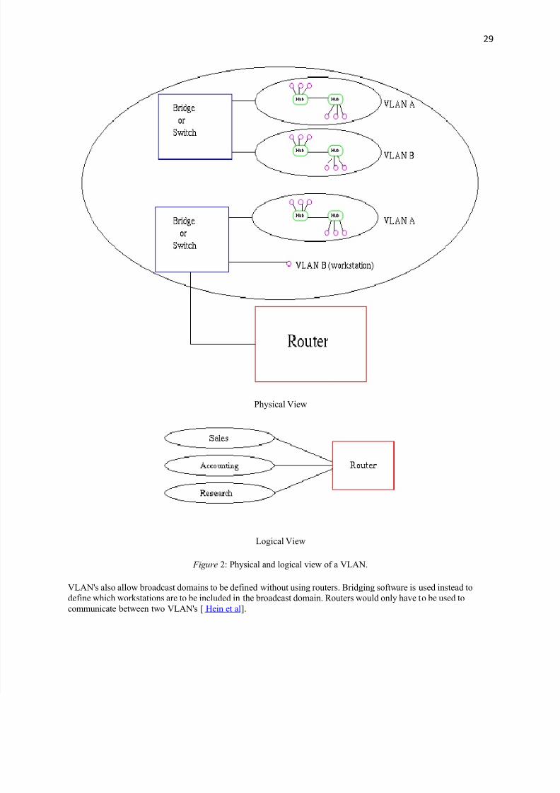
VLAN's allow a network manager to logically segment a LAN into different broadcast domains (see Fi gure2). Since
this is a logical segmentation and not a physical one, workstations do not have to be physically located together.
Users on different floors of the same building, or even in different buildings can now belong to the same LAN.
8/6/2019 Interview Basic IT
http://slidepdf.com/reader/full/interview-basic-it 29/29
29
Physical View
Logical View
Fi gure 2: Physical and logical view of a VLAN.
VLAN's also allow broadcast domains to be defined without using routers. Bridging software is used instead to
define which workstations are to be included in the broadcast domain. Routers would only have to be used to
communicate between two VLAN's [ Hein et al].


