Interstellar Probe using a Solar Sail: Conceptual Design...
10
1 Interstellar Probe using a Solar Sail: Conceptual Design and Technological Challenges P. C. Liewer 1 , R. A. Mewaldt 2 , J. A. Ayon 1 , C. Garner 1 , S. Gavit 1 , and R. A. Wallace 1 1 Jet Propulsion Laboratory, Pasadena, CA 91109 2 California Institute of Technology, Pasadena, CA 91125 NASA’s Interstellar Probe, conceived to travel to 200-400 AU, will be the first spacecraft designed specifically to explore the unknown regions beyond the solar system and directly sample the dust, neutrals and plasma of the surrounding interstellar material. Here we present the mission concept developed by NASA’s Interstellar Probe Science and Technology Definition Team in 1999 and discuss the technological challenges it presents. The Team selected a solar sail concept in which the spacecraft reaches 200 AU in 15 years. This rapid passage is made by using a 400-m diameter solar sail and heading first inward to ~0.25 AU to increase the radiation pressure. The Probe then heads out in the interstellar upwind direction at ~14/AU year, about 5 times the speed of the Voyager 1 and 2 spacecraft. Advanced lightweight instruments and spacecraft systems, as well as solar sail propulsion, are needed to achieve these high speeds. The spacecraft coasts to 200-400 AU, exploring the Kuiper Belt, the boundaries of the heliosphere, and the nearby interstellar medium. 1. INTRODUCTION Little is known about what lies beyond the solar system. NASA’s Interstellar Probe mission, which will travel to 200-400 AU, will be the first spacecraft designed to travel through the outer reaches of the solar system and sample the nearby interstellar material beyond the influence of our Sun. On its way, Interstellar Probe will explore the outer solar system and the boundaries of the heliosphere -- the bubble blown in the interstellar medium by the supersonic solar wind. Its unique trajectory allows the mission to address key questions about the nature of the primordial solar nebula, the structure and dynamics of our heliosphere, the properties of organic material in the outer solar system and interstellar medium, the nature of other stellar systems that may also harbor planets, the chemical evolution of our galaxy, and the origins of matter in the earliest days of the universe. As envisioned by NASA’s Interstellar Probe Science and Technology Definition Team, a 400-m solar sail would be used to carry the Probe to 200 AU in 15 years, with sufficient consumables (power, fuel) to last to 400 AU (30 years). The most critical advanced technology needed for this ambitious mission is solar sail propulsion, but advances in spacecraft subsystems and instruments are also necessary. This paper will present the Interstellar Probe concept developed by Team and discuss some of the advanced technologies needed.
Transcript of Interstellar Probe using a Solar Sail: Conceptual Design...
1
Interstellar Probe using a Solar Sail: Conceptual Design and Technological Challenges P. C. Liewer1, R. A. Mewaldt2, J. A. Ayon1, C. Garner1, S. Gavit1, and R. A. Wallace1
1Jet Propulsion Laboratory, Pasadena, CA 91109 2California Institute of Technology, Pasadena, CA 91125
NASA’s Interstellar Probe, conceived to travel to 200-400 AU, will be the first spacecraft designed specifically to explore the unknown regions beyond the solar system and directly sample the dust, neutrals and plasma of the surrounding interstellar material. Here we present the mission concept developed by NASA’s Interstellar Probe Science and Technology Definition Team in 1999 and discuss the technological challenges it presents. The Team selected a solar sail concept in which the spacecraft reaches 200 AU in 15 years. This rapid passage is made by using a 400-m diameter solar sail and heading first inward to ~0.25 AU to increase the radiation pressure. The Probe then heads out in the interstellar upwind direction at ~14/AU year, about 5 times the speed of the Voyager 1 and 2 spacecraft. Advanced lightweight instruments and spacecraft systems, as well as solar sail propulsion, are needed to achieve these high speeds. The spacecraft coasts to 200-400 AU, exploring the Kuiper Belt, the boundaries of the heliosphere, and the nearby interstellar medium. 1. INTRODUCTION
Little is known about what lies beyond the solar system. NASA’s Interstellar Probe mission, which will travel to 200-400 AU, will be the first spacecraft designed to travel through the outer reaches of the solar system and sample the nearby interstellar material beyond the influence of our Sun. On its way, Interstellar Probe will explore the outer solar system and the boundaries of the heliosphere -- the bubble blown in the interstellar medium by the supersonic solar wind. Its unique trajectory allows the mission to address key questions about the nature of the primordial solar nebula, the structure and dynamics of our heliosphere, the properties of organic material in the outer solar system and interstellar medium, the nature of other stellar systems that may also harbor planets, the chemical evolution of our galaxy, and the origins of matter in the earliest days of the universe. As envisioned by NASA’s Interstellar Probe Science and Technology Definition Team, a 400-m solar sail would be used to carry the Probe to 200 AU in 15 years, with sufficient consumables (power, fuel) to last to 400 AU (30 years). The most critical advanced technology needed for this ambitious mission is solar sail propulsion, but advances in spacecraft subsystems and instruments are also necessary. This paper will present the Interstellar Probe concept developed by Team and discuss some of the advanced technologies needed.

2
Table I. Interstellar Probe Science and Technology Definition Team
Chairman Richard Mewaldt, California Institute of Technology Study Scientist Paulett Liewer, Jet Propulsion Laboratory Program Manager Sarah Gavit, Jet Propulsion Laboratory Program Scientist Vernon Jones, NASA Headquarters Deputy Program Scientist James C. Ling, NASA Headquarters Program Executive Glenn H. Mucklow, NASA Headquarters NASA Transportation Dave Stone, NASA Interagency Representatives Dave Goodwin, DOE Eugene Loh, NSF Foreign Guest Participants Wolfgang Droege, University of Kiel, Germany Bernd Heber, Max Planck Institute for Aeronomy, Germany Claudio Maccone, Torino, Italy Jet Propulsion Laboratory Support Juan Ayon Charles Budney Eric De Jong Neil Murphy Richard Wallace
Members Emma Bakes, NASA Ames Research Center Priscilla Frisch, University of Chicago Herbert Funsten, Los Alamos National
Laboratory Mike Gruntman, University of Southern
California Les Johnson, Marshall Space Flight Center J. R. Jokipii, University of Arizona William Kurth, University of Iowa Jeffrey Linsky, University of Colorado Renu Malhotra, Lunar and Planetary Institute Ingrid Mann, California Institute of
Technology Ralph McNutt, John Hopkins University,
Applied Physics Laboratory Eberhard Moebius, University of New
Hampshire William Reach, California Institute of
Technology Steven T. Suess, Marshall Space Flight Center Adam Szabo, Goddard Space Flight Center Jim Trainor, Goddard Space Flight Center,
Retired Gary Zank, University of Delaware Thomas Zurbuchen, University of Michigan
The Interstellar Probe Science and Technology Definition Team (Table I) met during the
spring and summer of 1999 under sponsorship of the NASA Office of Space Science. The Team was charged with defining the science requirements and developing a concept for an interstellar probe mission for the Sun-Earth-Connection Roadmap, a part of NASA’s strategic planning activities. The resulting concept builds on several previous studies. In a 1990 study by Holzer et al., a 1000 kg spacecraft was to acquire data out to ~200 AU, exiting the solar system at ~10 AU/year using chemical propulsion coupled with impulsive maneuvers near the Sun. In a 1995 study of a smaller interstellar probe (Mewaldt et al., 1995), a ~200 kg spacecraft was to reach exit velocities of ~6 to 14 AU/year, depending on launch vehicle and trajectory, using chemical propulsion with planetary gravity assists or impulsive maneuvers near the Sun. Recent technological advances, notably lighter reflective sail materials (Garner et al., 1999; Garner and Leipold, 2000) and lighter spacecraft designs, now make it feasible to accomplish essentially the same mission using a solar sail to accelerate a 150 kg spacecraft to ~15 AU/year, allowing the mission to reach ~200 AU in ~15 years and ~400 AU in ~30 years .

3
2. SCIENCE OBJECTIVES AND SCIENTIFIC PAYLOAD
The Sun is thought to be located near the edge of a local interstellar cloud (LIC) of low density (~0.3 /cc) material blowing from the direction of star-forming regions in the constellations Scorpius and Centaurus. The solar wind, a continual low-density flux of charged particles, streams outward from the corona and expands supersonically throughout and beyond the solar system. The solar wind and the interstellar medium interact to create the global heliosphere, shown schematically in Fig. 1. The interaction between the solar wind, flowing radially outward at 400-800 km/sec, and the local interstellar material, flowing at ~25 km/sec, creates a complex structure extending perhaps 200-300 AU in the upstream (towards the local interstellar flow) direction and thousands of AU tailward. At present, there are no direct measurements of the size and structure of the heliosphere and our present understanding is based
on theory and modeling, constrained by a few key measurements. Voyager 1&2, now at approximately 78 and 61 AU respectively, should soon reach the first boundary in this complex structure, the solar wind termination shock, where the solar wind makes a transition from
FIGURE 1. The global heliosphere is created by the supersonic solar wind diverting the interstellar flow around the Sun. The interstellar ions and neutrals flow at 25 km/s relative to the Sun. The solar wind makes a transition to subsonic flow at the termination shock. Beyond this, the solar wind is turned toward the heliotail. The heliopause separates solar material and magnetic fields from interstellar material and fields.

4
supersonic to subsonic flow. Beyond the termination shock lies the heliopause, which is the boundary between solar wind and interstellar plasma. Several recent estimates place the distance to the termination shock at ~80 to 100 AU, with the heliopause at ~120 to 150 AU.
The heliosphere shields the solar system from the plasma, energetic particles, small dust, and fields of the interstellar medium. The local interstellar medium is thought to be younger material than that which formed the presolar nebulae and is expected to have a different elemental composition. Our present knowledge of the interstellar medium surrounding our heliosphere comes either from astronomical observations, measurements of sunlight resonantly scattered back towards us by interstellar H and He, or in situ measurements of the dust and neutral gas that penetrate the heliosphere. To observe these directly it is necessary to go beyond the heliopause. The Interstellar Probe Mission would be designed to travel beyond the region strongly influenced by the solar wind and make a significant penetration into nearby interstellar space.
Interstellar Probe’s unique voyage from Earth to beyond 200 AU will enable the first comprehensive measurements of plasma, neutrals, dust, magnetic fields, energetic particles, cosmic rays, and infrared emission from the outer solar system, through the boundaries of the heliosphere, and on into the ISM. This will allow the mission to address key questions about the distribution of matter in the outer solar system, the processes by which the Sun interacts with the galaxy, and the nature and properties of the nearby galactic medium. The principal scientific objectives of the Interstellar Probe mission as defined by the Team are to • Explore the nature of the interstellar medium and its implications for the origin and
evolution of matter in our Galaxy and the Universe; • Explore the influence of the interstellar medium on the solar system, its dynamics, and its
evolution; • Explore the impact of the solar system on the interstellar medium as an example of the
interaction of a stellar system with its environment; • Explore the outer solar system in search of clues to its origin, and to the nature of other
planetary systems. To achieve these broad, interdisciplinary objectives, the strawman scientific payload includes an advanced set of miniaturized, low-power instruments specifically designed to make comprehensive, in situ studies of the plasma, energetic particles, fields, and dust in the outer heliosphere and nearby ISM. These instruments will have capabilities that are generally far superior to those of the Voyagers. The wide variety of thermal and flow regimes to be encountered by Interstellar Probe will be explored by a comprehensive suite of neutral and charged particle instruments, including a solar wind and interstellar ion and electron detector, a spectrometer to measure the elemental and isotopic composition of pickup and interstellar ions, an interstellar neutral atom spectrometer, and a detector for suprathermal ions and electrons. Two cosmic ray instruments are included, one for H, He, electrons and positrons, and one to measure the energy spectra and composition of heavier anomalous and galactic cosmic rays. The magnetometer will make the first direct measurements of the magnetic fields in the ISM, and the plasma and radio wave detector will measure fluctuations in the electric and magnetic fields created by plasma processes and by interactions and instabilities in the heliospheric boundaries and beyond.

5
As the spacecraft transits the inner solar system to the ISM, the energetic neutral atom (ENA) imager will map the 3D structure of the termination shock and the UV photometer will probe the structure of the hydrogen wall, a localized region of increased neutral hydrogen density just beyond the heliopause. Dust will be studied with in situ measurements of the dust distribution and composition and by a remote sensing infrared photometer that will map the dust distribution via its infrared emission. The infrared detector will also detect galactic and cosmic infrared emission. At 1 AU, Zodiacal dust blocks a large portion of the Cosmic Infrared Background Radiation (CIRB) spectrum, but because the dust decreases with distance from the Sun, Interstellar Probe may be able to detect this emission as it moves out past 10 AU. Additional candidate instruments include a small telescope to survey kilometer-size Kuiper belt objects and additional particle instruments. The possibility of developing instrumentation to identify organic material in the outer solar system and the interstellar medium is also under study. The instruments and their development needs are discussed separately in Mewaldt et al (2000, this proceedings).
FIGURE 2. Left: The hexagonal ~400 m diameter solar sail with the spin up booms still attached. Right: The spacecraft, whose 2.7 m dish antenna serves and the main structure, is supported by three struts in an 11-m hole in the center of the solar sail. Sail control is achieved by moving the spacecraft with respect to the center of mass of the sail. The instruments are attached near the rim of the antenna. The sail is spin-stabilized during sailing.
3. MISSION CONCEPT
Interstellar Probe mission requirements were defined by the ISPSTDT. To accomplish its science objectives, the probe should acquire data out to a distance of at least 200 AU, with a goal of ~400 AU. The trajectory should aim for the nose of the heliosphere, the shortest route to the interstellar medium. The average science data rate at 200 AU would be 25 bps; a lower data rate is acceptable at 400 AU. The instrument payload requires ~25 kg and ~20 watts of power. The spacecraft should spin to enable the in situ instruments to scan the particle, plasma, and magnetic field distributions and to permit the remote-sensing instruments to scan the sky.

6
The concept developed by JPL’s mission design team met all requirements. The resulting spacecraft is shown in Figure 2 (right) in sailing configuration. The spacecraft is suspended inside an 11-m hole in the 400-m diameter hexagonal sail. The instruments are placed around the rim of a 2.7-m dish antenna, which also functions as the main support structure. The spacecraft is designed for a mission to 200 AU with consumables to last to 400 AU (~30 year mission). Science and engineering data are gathered at an average rate of 30 bps. The telecommunications system uses Ka band to communicate with the Deep Space Network; data is stored and dumped using approximately 1 pass per week. The antenna is
limited to 2.7 m to fit in the shroud of the Delta II launch vehicle. A downlink data rate of 350 bps at 200 AU is achieved using a transmitter requiring 220 W. Power is provided by three next-generation advanced radioisotope power source (ARPS) units.
The total spacecraft mass (excluding sail) is ~150 kg including the instruments. To
achieve the 15 AU/year exit velocity, a solar sail with 1 g/m2 areal density (sail material plus support structure) and a radius of ~200 m is needed. The total accelerated mass (spacecraft plus sail system) is ~246 kg. The trajectory is shown in Fig. 3. The spacecraft initially goes in to 0.25 AU to obtain increased radiation pressure before heading out towards the nose of the heliosphere. The sail is jettisoned at ~5 AU when the further acceleration from radiation pressure becomes negligible, thereby avoiding potential interference with the instruments. Figure 3 also shows the orientation of the sail relative to the Sun to obtain the proper thrust vector for the trajectory shown. The total ΔV achieved is 70 km/s. In the sailing configuration, shown in Fig. 2 (right), the spacecraft is supported within a hole in the center of the sail by 3 struts. Sail control is achieved by offsetting the spacecraft with respect to the center-of-mass of the sail by varying the length of the struts.
FIGURE 3. Interstellar Probe trajectory using a solar sail to reach a final velocity of 15 AU/year. The trajectory is towards the nose of the heliosphere, the shortest route to the interstellar medium. The orientation of the sail to achieve the proper thrust vector is also shown.
7
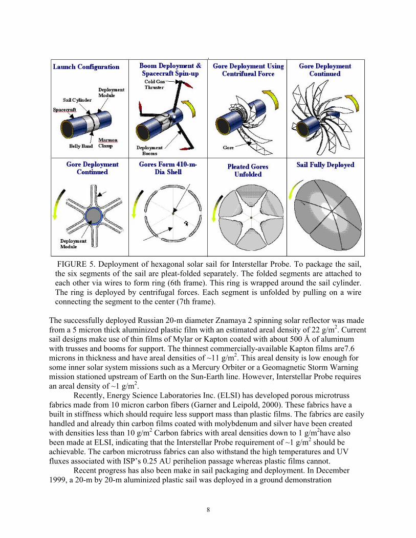
The sail is deployed and stabilized by rotation; a number of mechanisms used to provide the initial spin up and deployment of the sail are jettisoned after sail deployment. Figure 2 (left) shows the sail after deployment, but with the spin-up booms still attached. One possible method for folding and deploying the sail is illustrated in Fig. 5. Initially, each segment of the hexagonal sail is pleat-folded; the six segments are connected in a ring by a wire (see sixth frame of Fig. 5) and wrapped around the sail cylinder. After the folded segments are
deployed into a ring by centrifugal force, the segments are unfolded by pulling towards the cylinder (analogous to pulling down a pleated window shade).
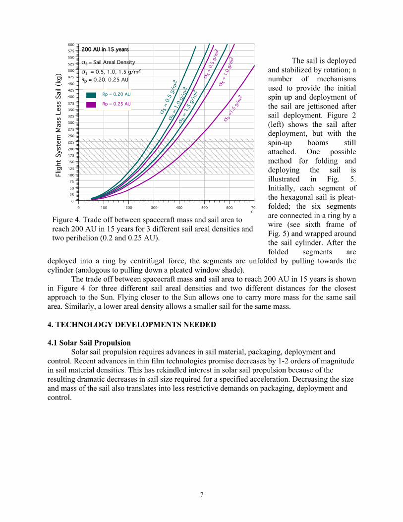
The trade off between spacecraft mass and sail area to reach 200 AU in 15 years is shown in Figure 4 for three different sail areal densities and two different distances for the closest approach to the Sun. Flying closer to the Sun allows one to carry more mass for the same sail area. Similarly, a lower areal density allows a smaller sail for the same mass. 4. TECHNOLOGY DEVELOPMENTS NEEDED 4.1 Solar Sail Propulsion
Solar sail propulsion requires advances in sail material, packaging, deployment and control. Recent advances in thin film technologies promise decreases by 1-2 orders of magnitude in sail material densities. This has rekindled interest in solar sail propulsion because of the resulting dramatic decreases in sail size required for a specified acceleration. Decreasing the size and mass of the sail also translates into less restrictive demands on packaging, deployment and control.
0 100 200 300 400 500 600 700
0
25
50
75
100
125
150
175
200
225
250
275
300
325
350
375
400
425
450
475
500
525
550
575
600200 AU in 15 years
σs = Sail Areal Density
σs = 0.5, 1.0, 1.5 g/m2 Rp = 0.20, 0.25 AU
σ s =
0.5
g/m
2
Flig
ht S
yste
m M
ass
Less
Sai
l (kg
)
σ s =
1.0
g/m
2
Rp = 0.25 AU
Rp = 0.20 AU
σ s =
0.5
g/m
2
σ s =
1.5
g/m
2
σ s =
1.0
g/m
2σ s
=1.5
g/m
2
Figure 4. Trade off between spacecraft mass and sail area to reach 200 AU in 15 years for 3 different sail areal densities and two perihelion (0.2 and 0.25 AU).
8
FIGURE 5. Deployment of hexagonal solar sail for Interstellar Probe. To package the sail, the six segments of the sail are pleat-folded separately. The folded segments are attached to each other via wires to form ring (6th frame). This ring is wrapped around the sail cylinder. The ring is deployed by centrifugal forces. Each segment is unfolded by pulling on a wire connecting the segment to the center (7th frame).
The successfully deployed Russian 20-m diameter Znamaya 2 spinning solar reflector was made from a 5 micron thick aluminized plastic film with an estimated areal density of 22 g/m2. Current sail designs make use of thin films of Mylar or Kapton coated with about 500 Å of aluminum with trusses and booms for support. The thinnest commercially-available Kapton films are7.6 microns in thickness and have areal densities of ~11 g/m2. This areal density is low enough for some inner solar system missions such as a Mercury Orbiter or a Geomagnetic Storm Warning mission stationed upstream of Earth on the Sun-Earth line. However, Interstellar Probe requires an areal density of ~1 g/m2.
Recently, Energy Science Laboratories Inc. (ELSI) has developed porous microtruss fabrics made from 10 micron carbon fibers (Garner and Leipold, 2000). These fabrics have a built in stiffness which should require less support mass than plastic films. The fabrics are easily handled and already thin carbon films coated with molybdenum and silver have been created with densities less than 10 g/m2 Carbon fabrics with areal densities down to 1 g/m2have also been made at ELSI, indicating that the Interstellar Probe requirement of ~1 g/m2 should be achievable. The carbon microtruss fabrics can also withstand the high temperatures and UV fluxes associated with ISP’s 0.25 AU perihelion passage whereas plastic films cannot.
Recent progress has also been make in sail packaging and deployment. In December 1999, a 20-m by 20-m aluminized plastic sail was deployed in a ground demonstration

9
technology test at DLR in Cologne, Germany (see http://solarsystem.dlr.de/MT/solarsail/new.shtml). Three different films were used for the four quadrants, which were supported by carbon trusses. Presently, sail technology developments in many different areas are being supported by both by NASA and ESA. 4.2 Power Systems
The baseline spacecraft concept for Interstellar Probe uses three 8.5 kg next generation Advanced Radioisotope Power System (ARPS) units with Alkali Metal Thermal-to-Electric Converters (AMTEC)(see e.g., Schock et al., 1999). Each initially delivers 106 W, but degrades at a projected rate of 1 Watt/year, yielding a total of 228 W after 30 years. The AMTEC ARPS is under development by NASA and DOE for NASA and is expected to be technology ready at the end of 2002 but additional time will be necessary to complete testing and life models to project a 30 year lifetime with confidence.
A Stirling cycle ARPS (see e.g., Or et al., 1999), which is currently baselined for the Europa Orbiter (2006) and Solar Probe (2007) missions, is probably too heavy for the current ISP solar sail mission concept; current designs suggest a Stirling cycle ARPS will be at least double the mass per Watt compared to the AMTEC designs. Moreover, because the Stirling cycle converter uses a reciprocating dynamic engine with a permanent magnetic linear alternator, there are serious magnetic cleanliness concerns associated with its use for ISP. The existing RTG's flown on Galileo, Ulysses, Cassini and currently proposed for Pluto-Kuiper Express (2004) also have low power outputs per unit mass (specific power of ~5 W/kg) making them too massive for the ISP solar sail concept. 5. CONCLUSIONS ISP will explored unknown regions beyond the solar system addressing a broad, interdisciplinary range of science objectives. To accomplish this ambitious mission, technology development is needed for solar sail propulsion, spacecraft power subsystems, and also instruments (see Mewaldt et al., these proceedings.) The mission concept presented here also assumes a number of developments in other spacecraft systems, including low-power avionics and phased-array Ka-band telecommunications. Many of these developments are also being counted on for other future NASA missions.
The most critical technology needed to carry out the mission described here is solar sail propulsion. Although solar sails have been studied extensively (Wright, 1992), they have never flown in space (although a large ~20 m sail was deployed on MIR). These developments will have to be tested in one or more flight demonstrations before a 400-m sail with an areal density of ~1 g/m2 will be ready for flight, requiring an aggressive solar-sail development program (see, e.g., Wallace, 1999). Fortunately, there are also a large number of other missions that could benefit from solar-sail propulsion. If this program is successful, launch could be as early as 2010, and Interstellar Probe can serve as the first step in a more ambitious program to explore the outer solar system and nearby galactic neighborhood. 6. ACKNOWLEDGMENTS A portion of this work was conducted at the Jet Propulsion Laboratory, California Institute of Technology under contract with the National Aeronautics and Space Administration. We thank

10
Bill Nesmith for information on the advanced power systems. We would also like to acknowledge the help of E. Danielson, JPL; R. Forward, Forward Unlimited; T. Linde, U. of Chicago; J. Ormes, GSFC; M. Ressler, JPL; T. Wdowiak, U. of Alabama at Birmingham; M. Wiedenbeck, JPL; the JPL Advanced Project Design Team (Team X), led by R. Oberto; and additional members of the JPL Interstellar Program: S. D’Agostino, K. Evans, W. Fang, R. Frisbee, H. Garrett, S. Leifer, R. Miyake, N. Murphy, F. Pinto, G. Sprague, P. Willis, and K. Wilson. REFERENCES Garner, C. E., Diedrich, B., and Leipold, M., “A Summary of Solar Sail Technology
Developments and Proposed Demonstration Missions,” AIAA-99-2697, presented at 35th AIAA Joint Propulsion Conference, Los Angeles, CA, June, 1999.
Garner, C. and Leipold, M., “Developments and Activities in Solar Sail Propulsion,” AIAA-00-0126. Presented at 36th AIAA Joint Propulsion Conference, 2000.
Holzer, T. E., Mewaldt, R. A., and Neugebauer, M., The Interstellar Probe: Scientific Objectives and Requirements for a Frontier Mission to the Heliospheric Boundary and Interstellar Space, Report of the Interstellar Probe Workshop, Ballston, VA, 1990.
Mewaldt, R. A., Kangas, J., Kerridge, S. J., and Neugebauer, M., “A Small Interstellar Probe to the Heliospheric Boundary and Interstellar Space”, Acta Astronautica, 35 Suppl., 267-276 (1995).
Or, C., Carpenter, R., Schock, A. and Kumar, V., "Performance of the Preferred Self-Supporting Radioisotope Power System With STC 55-W Stirling Converters", Space Technology and Applications International Forum, 1999.
Schock, A., Noravian, H., Or, C. and Kumar, V., “Recommended OSC Design and Analysis of AMTEC Power System for Outer-Planet Missions", Space Technology and Applications International Forum, 1999.
Wright, J. L., Space Sailing, Gordon and Breach, Amsterdam, 1992. Wallace, R. A., “Precursor Missions to Interstellar Exploration,” Proc. IEEE Aerospace Conf.,
Aspen, CO, (1999) Paper 114.