
Interrupt handling - · PDF file2 Interrupt handling An embedded system has to handle many...
70
Transcript of Interrupt handling - · PDF file2 Interrupt handling An embedded system has to handle many...

CHAPTER 1 Interrupt handling
Handling interrupts is at the heart of an embedded system. By managing the inter-action with external systems through effective use of interrupts can dramatically improve system efficiency and the use of processing resources. The actual process of determining a good handling method can be complicated, challenging and fun. Numerous actions are occurring simultaneously at a single point and these actions have to be handled fast and efficiently. This chapter will provide a practical guide to designing an interrupt handler and discuss the various trade-offs between the different methods. The methods covered will be as follows:
• Non-nested interrupt handler
• Nested interrupt handler
• Re-entrant nested interrupt handler
• Prioritized interrupt handler
Embedded systems have to handle real world events such as the detection of a key being pressed, synchonization of video output, or handle the transmission and reception of data packets for a communication device. These events have to be han-dled in real time, which means an action has to take place within a particular time period to process the event. For instance, when a key is pressed on an embedded system it has to respond quickly enough so that the user can see a character appear-ing on the screen, without any noticeable delay. If an inordinate delay occurs the user will perceive the system as being non-responsive.
Interrupt handling 1
Interrupt handling
2
An embedded system has to handle many events. An event halts the normal flow of the processor. For ease of explanation, events can be divided into two types, planned and unplanned. Planned events are events such as a key being pressed, a timer producing an interrupt periodically, and software interrupt. Unplanned events are data aborts, instruction aborts, and undefined instruction aborts. In this chapter planned events will be called interrupts and unplanned events will be called excep-tions. When an event occurs the normal flow of execution from one instruction to the next is halted and re-directed to another instruction that is designed specifically to handle that event. Once the event has been serviced the processor can resume normal execution by setting the program counter to point to the instruction after the instruction that was halted (except for data and prefetch abort, where instructions may have to be re-executed).
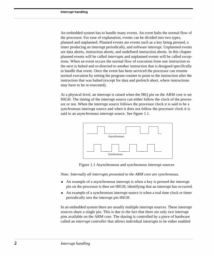
At a physical level, an interrupt is raised when the IRQ pin on the ARM core is set HIGH. The timing of the interrupt source can either follow the clock of the proces-sor or not. When the interrupt source follows the processor clock it is said to be a synchronous interrupt source and when it does not follow the processor clock it is said to an asynchronous interrupt source. See figure 1.1.
Figure 1.1 Asynchronous and synchronous interrupt sources
Note: Internally all interrupts presented to the ARM core are synchronous.
• An example of a asynchronous interrupt is when a key is pressed the interrupt pin on the processor is then set HIGH; identifying that an interrupt has occurred.
• An example of a synchronous interrupt source is when a real time clock or timer periodically sets the interrupt pin HIGH.
In an embedded system there are usually multiple interrupt sources. These interrupt sources share a single pin. This is due to the fact that there are only two interrupt pins available on the ARM core. The sharing is controlled by a piece of hardware called an interrupt controller that allows individual interrupts to be either enabled
Asynchronous
Synchronous
Interrupt handling
or disabled. The controller provides a set of programmable registers, which can be used to read or write masks and obtain the interrupt status.
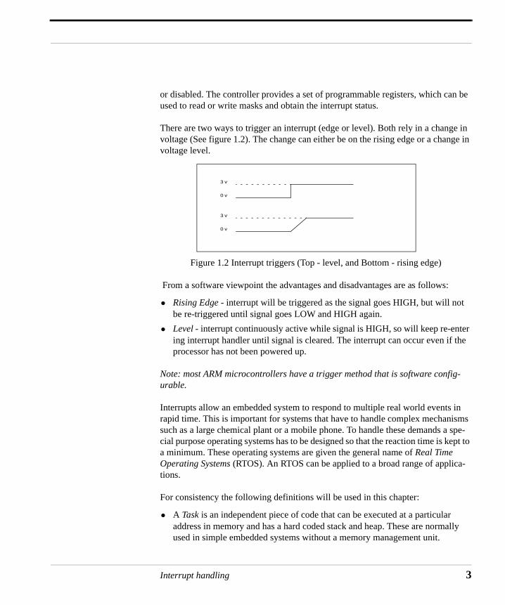
There are two ways to trigger an interrupt (edge or level). Both rely in a change in voltage (See figure 1.2). The change can either be on the rising edge or a change in voltage level.
Figure 1.2 Interrupt triggers (Top - level, and Bottom - rising edge)
From a software viewpoint the advantages and disadvantages are as follows:
• Rising Edge - interrupt will be triggered as the signal goes HIGH, but will not be re-triggered until signal goes LOW and HIGH again.
• Level - interrupt continuously active while signal is HIGH, so will keep re-enter ing interrupt handler until signal is cleared. The interrupt can occur even if the processor has not been powered up.
Note: most ARM microcontrollers have a trigger method that is software config-urable.
Interrupts allow an embedded system to respond to multiple real world events in rapid time. This is important for systems that have to handle complex mechanisms such as a large chemical plant or a mobile phone. To handle these demands a spe-cial purpose operating systems has to be designed so that the reaction time is kept to a minimum. These operating systems are given the general name of Real Time Operating Systems (RTOS). An RTOS can be applied to a broad range of applica-tions.
For consistency the following definitions will be used in this chapter:
• A Task is an independent piece of code that can be executed at a particular address in memory and has a hard coded stack and heap. These are normally used in simple embedded systems without a memory management unit.
3 v
3 v
0 v
0 v
Interrupt handling 3
Interrupt handling
4
• A Process is like a task except that it executes in its own virtual address space and has a stack and heap located within that virtual space. Processes can be implemented on embedded systems that include a special device that changes address space and paging (Memory Management Unit).
• Threads are similar to processes but can easily be assigned to be executed on a different processor. For instance, a Symmetric Multi-Processor (SMP) systems can have different threads running on different processors.
To handle multiple tasks a RTOS uses a number of different scheduling methods. Each method has different advantages and disadvantages depending upon the appli-cation. It is important that the tasks can communicate with each other, since they will probably have to share resources (memory or peripherals). The resources are normally protected by some mechanism, such as a semaphore (which will be dis-cussed in more detail later on in this chapter), so that only one task can access the resource at a time. If the sharing of data is possible then a message passing system can be adopted to help communication between the various tasks. Message passing allows a task to pass data and control to another task without taking valuable resources away from the entire embedded system.
The actual mechanism for swapping tasks is called a context switch. Preemptive RTOS context switching occurs periodically when a timer interrupt is raised. The context switch will first save the state of the currently active task and then will restore the state of the next task to be active. The next task chosen depends upon the scheduling algorithm (i.e. round robin) adopted.
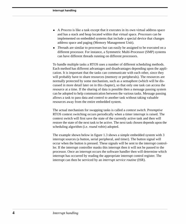
The example shown below in figure 1.3 shows a simple embedded system with 3 interrupt sources (a button, serial peripheral, and timer). The button signal will occur when the button is pressed. These signals will be sent to the interrupt control-ler. If the interrupt controller masks this interrupt then it will not be passed to the processor. Once an interrupt occurs the software handler then will determine which interrupt has occurred by reading the appropriate interrupt control register. The interrupt can then be serviced by an interrupt service routine (ISR).
Interrupt handling
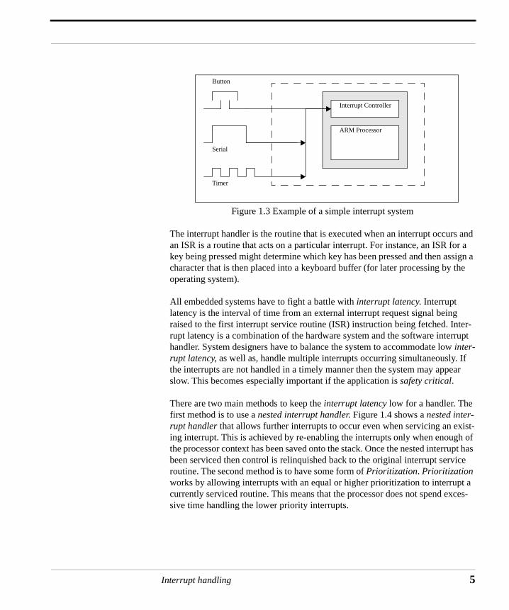
Figure 1.3 Example of a simple interrupt system
The interrupt handler is the routine that is executed when an interrupt occurs and an ISR is a routine that acts on a particular interrupt. For instance, an ISR for a key being pressed might determine which key has been pressed and then assign a character that is then placed into a keyboard buffer (for later processing by the operating system).
All embedded systems have to fight a battle with interrupt latency. Interrupt latency is the interval of time from an external interrupt request signal being raised to the first interrupt service routine (ISR) instruction being fetched. Inter-rupt latency is a combination of the hardware system and the software interrupt handler. System designers have to balance the system to accommodate low inter-rupt latency, as well as, handle multiple interrupts occurring simultaneously. If the interrupts are not handled in a timely manner then the system may appear slow. This becomes especially important if the application is safety critical.
There are two main methods to keep the interrupt latency low for a handler. The first method is to use a nested interrupt handler. Figure 1.4 shows a nested inter-rupt handler that allows further interrupts to occur even when servicing an exist-ing interrupt. This is achieved by re-enabling the interrupts only when enough of the processor context has been saved onto the stack. Once the nested interrupt has been serviced then control is relinquished back to the original interrupt service routine. The second method is to have some form of Prioritization. Prioritization works by allowing interrupts with an equal or higher prioritization to interrupt a currently serviced routine. This means that the processor does not spend exces-sive time handling the lower priority interrupts.
ARM Processor
Interrupt Controller
Button
Serial
Timer
Interrupt handling 5
Interrupt handling
6
Figure 1.4 A three level nested interrupt
If the embedded system is memory constrained. Then the handler and the ISR should be written in Thumb code since Thumb provides higher code density on the ARM processor. If Thumb code is used then the designer has to be careful in swap-ping the processor back into Thumb state when an interrupt occurs since the ARM processor automatically reverts back to ARM state when an exception or interrupt is raised. The entry and exit code in an interrupt handler must be written in ARM code, since the ARM automatically switches to ARM state when servicing an exception or interrupt. The exit code must be in ARM state, because the Thumb instruction set does not contain the instructions required to return from an exception or interrupt. As mentioned above the main body of the interrupt handler can be in Thumb code to take advantage of code density and faster execution from 16-bit or 8-bit memory devices.
The rest of the chapter will cover these topics in more detail:
• ARM Processor
• Event priorities
• Vector table
• Controlling interrupts
• Setting up the interrupt stacks
• Installing and chaining interrupt handlers
• Simple non-nested interrupt handler
• Nested interrupt handler
• Re-entrant nested interrupt handler
Interrupt (1)
Interrupt (2)
Interrupt (3)
Normal Execution
Return
Return
Return
Interrupt handler
Safe area
Interrupt handling
• Prioritized interrupt handler (1) - Simple
• Prioritized interrupt handler (2) - Standard
• Prioritized interrupt handler (3) - Direct
• Prioritized interrupt handler (4) - Grouped
• Interworking with ARM and Thumb
• Context switching
• Semaphores
• Debug
• General notes for Real Time Operating Systems
Notation: banked registers r13 and r14 are notated as:
r13_<mode> or sp_<mode>r14_<mode> or lr_<mode>
Interrupt handling 7
Interrupt handling
8
ARM Processor
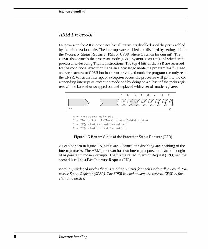
On power-up the ARM processor has all interrupts disabled until they are enabled by the initialization code. The interrupts are enabled and disabled by setting a bit in the Processor Status Registers (PSR or CPSR where C stands for current). The CPSR also controls the processor mode (SVC, System, User etc.) and whether the processor is decoding Thumb instructions. The top 4 bits of the PSR are reserved for the conditional execution flags. In a privileged mode the program has full read and write access to CPSR but in an non-privileged mode the program can only read the CPSR. When an interrupt or exception occurs the processor will go into the cor-responding interrupt or exception mode and by doing so a subset of the main regis-ters will be banked or swapped out and replaced with a set of mode registers.
M = Processor Mode BitT = Thumb Bit (1=Thumb state 0=ARM state)I = IRQ (1=disabled 0=enabled)F = FIQ (1=disabled 0=enabled)
Figure 1.5 Bottom 8-bits of the Processor Status Register (PSR)
As can be seen in figure 1.5, bits 6 and 7 control the disabling and enabling of the interrupt masks. The ARM processor has two interrupt inputs both can be thought of as general purpose interrupts. The first is called Interrupt Request (IRQ) and the second is called a Fast Interrupt Request (FIQ).
Note: In privileged modes there is another register for each mode called Saved Pro-cessor Status Register (SPSR). The SPSR is used to save the current CPSR before changing modes.
I F T M M M M M
7 6 5 4 3 2 1 0
031
Interrupt handling
ARM Processor
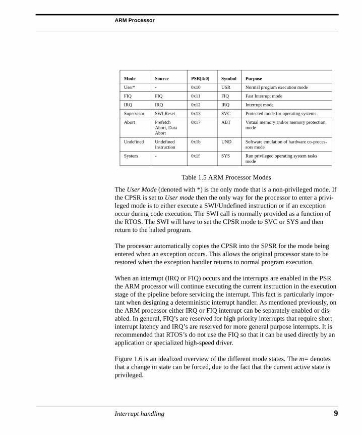
Table 1.5 ARM Processor Modes
The User Mode (denoted with *) is the only mode that is a non-privileged mode. If the CPSR is set to User mode then the only way for the processor to enter a privi-leged mode is to either execute a SWI/Undefined instruction or if an exception occur during code execution. The SWI call is normally provided as a function of the RTOS. The SWI will have to set the CPSR mode to SVC or SYS and then return to the halted program.
The processor automatically copies the CPSR into the SPSR for the mode being entered when an exception occurs. This allows the original processor state to be restored when the exception handler returns to normal program execution.
When an interrupt (IRQ or FIQ) occurs and the interrupts are enabled in the PSR the ARM processor will continue executing the current instruction in the execution stage of the pipeline before servicing the interrupt. This fact is particularly impor-tant when designing a deterministic interrupt handler. As mentioned previously, on the ARM processor either IRQ or FIQ interrupt can be separately enabled or dis-abled. In general, FIQ’s are reserved for high priority interrupts that require short interrupt latency and IRQ’s are reserved for more general purpose interrupts. It is recommended that RTOS’s do not use the FIQ so that it can be used directly by an application or specialized high-speed driver.
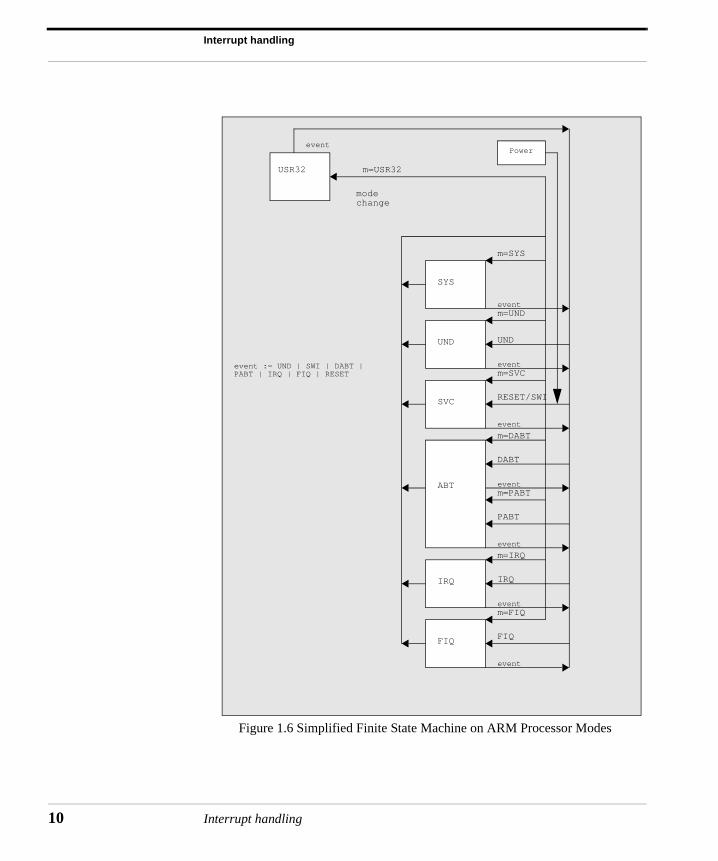
Figure 1.6 is an idealized overview of the different mode states. The m= denotes that a change in state can be forced, due to the fact that the current active state is privileged.
Mode Source PSR[4:0] Symbol Purpose
User* - 0x10 USR Normal program execution mode
FIQ FIQ 0x11 FIQ Fast Interrupt mode
IRQ IRQ 0x12 IRQ Interrupt mode
Supervisor SWI,Reset 0x13 SVC Protected mode for operating systems
Abort Prefetch Abort, Data Abort
0x17 ABT Virtual memory and/or memory protection mode
Undefined Undefined Instruction
0x1b UND Software emulation of hardware co-proces-sors mode
System - 0x1f SYS Run privileged operating system tasks mode
Interrupt handling 9
Interrupt handling
10
Figure 1.6 Simplified Finite State Machine on ARM Processor Modes
m=SYS
m=UND
m=SVC
m=DABT
m=PABT
m=IRQ
m=FIQ
m=USR32
IRQ
FIQ
PABT
DABT
RESET/SWI
UND
event
event
event
event
event
event
event
event := UND | SWI | DABT |PABT | IRQ | FIQ | RESET
modechange
event
SYS
UND
SVC
IRQ
FIQ
USR32
Power
ABT
Interrupt handling
Int
ARM Processor
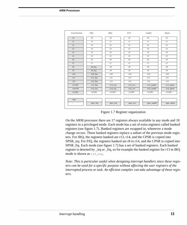
Figure 1.7 Register organization
On the ARM processor there are 17 registers always available in any mode and 18 registers in a privileged mode. Each mode has a set of extra registers called banked registers (see figure 1.7). Banked registers are swapped in, whenever a mode change occurs. These banked registers replace a subset of the previous mode regis-ters. For IRQ, the registers banked are r13, r14, and the CPSR is copied into SPSR_irq. For FIQ, the registers banked are r8 to r14, and the CPSR is copied into SPSR_fiq. Each mode (see figure 1.7) has a set of banked registers. Each banked register is denoted by _irq or _fiq, so for example the banked register for r13 in IRQ mode is shown as r13_irq.
Note: This is particular useful when designing interrupt handlers since these regis-ters can be used for a specific purpose without affecting the user registers of the interrupted process or task. An efficient compiler can take advantage of these regis-ters.
r0
r1
r9
r2
r3
r4
r5
r6
r7
r8
r10
r11
r14/LR
r12
r13/SP
r15/PC
cpsr
-
r0
r1
r9_fiq
r2
r3
r4
r5
r6
r7
r8_fiq
r10_fiq
r11_fiq
r14_fiq
r12_fiq
r13_fiq
r15/PC
-
spsr_fiq
r0
r1
r9
r2
r3
r4
r5
r6
r7
r8
r10
r11
r14_irq
r12
r13_irq
r15/PC
-
spsr_irq
r0
r1
r9
r2
r3
r4
r5
r6
r7
r8
r10
r11
r14_svc
r12
r13_svc
r15/PC
-
spsr_svc
r0
r1
r9
r2
r3
r4
r5
r6
r7
r8
r10
r11
r14_undef
r12
r13_undef
r15/PC
-
spsr_undef
r0
r1
r9
r2
r3
r4
r5
r6
r7
r8
r10
r11
r14_abort
r12
r13_abort
r15/PC
-
spsr_abort
User/System FIQ IRQ SVC Undef Abort
errupt handling 11
Interrupt handling
12
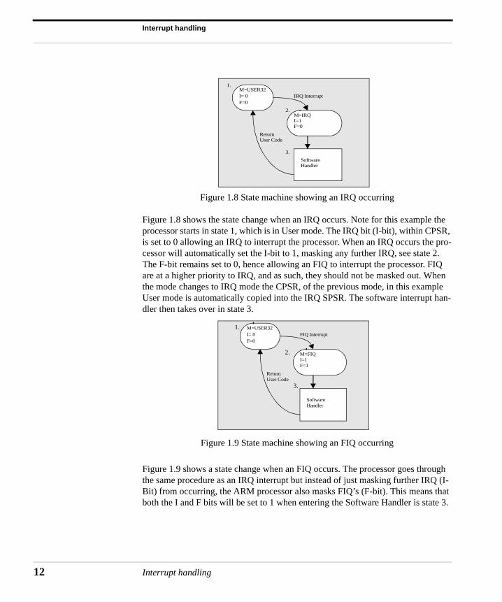
Figure 1.8 State machine showing an IRQ occurring
Figure 1.8 shows the state change when an IRQ occurs. Note for this example the processor starts in state 1, which is in User mode. The IRQ bit (I-bit), within CPSR, is set to 0 allowing an IRQ to interrupt the processor. When an IRQ occurs the pro-cessor will automatically set the I-bit to 1, masking any further IRQ, see state 2. The F-bit remains set to 0, hence allowing an FIQ to interrupt the processor. FIQ are at a higher priority to IRQ, and as such, they should not be masked out. When the mode changes to IRQ mode the CPSR, of the previous mode, in this example User mode is automatically copied into the IRQ SPSR. The software interrupt han-dler then takes over in state 3.
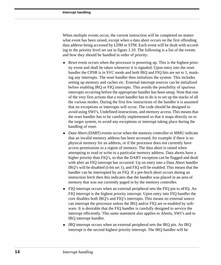
Figure 1.9 State machine showing an FIQ occurring
Figure 1.9 shows a state change when an FIQ occurs. The processor goes through the same procedure as an IRQ interrupt but instead of just masking further IRQ (I-Bit) from occurring, the ARM processor also masks FIQ’s (F-bit). This means that both the I and F bits will be set to 1 when entering the Software Handler is state 3.
I= 0F=0
M=FIQI=1F=1
M=USER32FIQ Interrupt
Software Handler
ReturnUser Code
1.
2.
3.
I= 0F=0
M=IRQI=1F=0
M=USER32IRQ Interrupt
Software Handler
ReturnUser Code
1.
2.
3.
Interrupt handling
Event priorities
In FIQ mode there is no requirement to save r8 to r12. This means these registers can be used to hold temporary data, such as buffer pointers or counters. This makes FIQ’s ideal for servicing single source high-priority, low-latency interrupts.
Event priorities
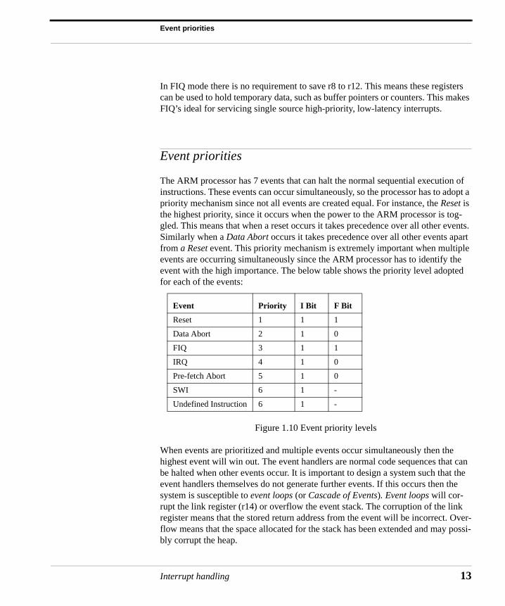
The ARM processor has 7 events that can halt the normal sequential execution of instructions. These events can occur simultaneously, so the processor has to adopt a priority mechanism since not all events are created equal. For instance, the Reset is the highest priority, since it occurs when the power to the ARM processor is tog-gled. This means that when a reset occurs it takes precedence over all other events. Similarly when a Data Abort occurs it takes precedence over all other events apart from a Reset event. This priority mechanism is extremely important when multiple events are occurring simultaneously since the ARM processor has to identify the event with the high importance. The below table shows the priority level adopted for each of the events:
Figure 1.10 Event priority levels
When events are prioritized and multiple events occur simultaneously then the highest event will win out. The event handlers are normal code sequences that can be halted when other events occur. It is important to design a system such that the event handlers themselves do not generate further events. If this occurs then the system is susceptible to event loops (or Cascade of Events). Event loops will cor-rupt the link register (r14) or overflow the event stack. The corruption of the link register means that the stored return address from the event will be incorrect. Over-flow means that the space allocated for the stack has been extended and may possi-bly corrupt the heap.
Event Priority I Bit F Bit
Reset 1 1 1
Data Abort 2 1 0
FIQ 3 1 1
IRQ 4 1 0
Pre-fetch Abort 5 1 0
SWI 6 1 -
Undefined Instruction 6 1 -
Interrupt handling 13
Interrupt handling
14
When multiple events occur, the current instruction will be completed no matter what event has been raised, except when a data abort occurs on the first offending data address being accessed by LDM or STM. Each event will be dealt with accord-ing to the priority level set out in figure 1.10. The following is a list of the events and how they should be handled in order of priority:
• Reset event occurs when the processor is powering up. This is the highest prior-ity event and shall be taken whenever it is signaled. Upon entry into the reset handler the CPSR is in SVC mode and both IRQ and FIQ bits are set to 1, mask-ing any interrupts. The reset handler then initializes the system. This includes setting up memory and caches etc. External interrupt sources can be initialized before enabling IRQ or FIQ interrupts. This avoids the possibility of spurious interrupts occurring before the appropriate handler has been setup. Note that one of the very first actions that a reset handler has to do is to set up the stacks of all the various modes. During the first few instructions of the handler it is assumed that no exceptions or interrupts will occur. The code should be designed to avoid using SWI’s, Undefined instructions, and memory access. This means that the reset handler has to be carefully implemented so that it maps directly on to the target system, to avoid any exceptions or interrupt taking place during the handling of reset.
• Data Abort (DABT) events occur when the memory controller or MMU indicate that an invalid memory address has been accessed, for example if there is no physical memory for an address, or if the processor does not currently have access permissions to a region of memory. The data abort is raised when attempting to read or write to a particular memory address. Data aborts have a higher priority than FIQ’s, so that the DABT exception can be flagged and dealt with after an FIQ interrupt has occurred. Up on entry into a Data Abort handler IRQ’s will be disabled (I-bit set 1), and FIQ will be enabled. This means that the handler can be interrupted by an FIQ. If a pre-fetch abort occurs during an instruction fetch then this indicates that the handler was placed in an area of memory that was not currently paged in by the memory controller.
• FIQ interrupt occurs when an external peripheral sets the FIQ pin to nFIQ. An FIQ interrupt is the highest priority interrupt. Upon entry into FIQ handler the core disables both IRQ’s and FIQ’s interrupts. This means no external source can interrupt the processor unless the IRQ and/or FIQ are re-enabled by soft-ware. It is desirable that the FIQ handler is carefully designed to service the interrupt efficiently. This same statement also applies to Aborts, SWI’s and to IRQ interrupt handler.
• IRQ interrupt occurs when an external peripheral sets the IRQ pin. An IRQ interrupt is the second highest priority interrupt. The IRQ handler will be
Interrupt handling
Vector table
entered, if neither a FIQ interrupt or data abort event has occurred. Upon entry to the IRQ handler the IRQ interrupts are disabled. The IRQ’s (I-bit) should remain disabled until the current interrupt source has been cleared.
• Pre-fetch Abort event occurs when an attempt to load an instruction results in a memory fault. This exception only occurs if the instruction reaches the execu-tion stage of the pipeline, and if none of the higher exceptions/interrupts have been raised. Upon entry to the handler IRQ’s will be disabled, but the FIQ inter-rupts will remain enabled. If an FIQ interrupt occurs it can be taken while ser-vicing the Pre-fetch abort.
• SWI interrupt occurs when the SWI instruction has been fetched and decoded successfully, and none of the other higher priority exceptions/interrupts have been flagged. Upon entry to the handler the CPSR will be set to SVC mode. Note: if a SWI calls another SWI (which is a common occurrence), then to avoid corruption, the link register (LR & SPSR) must be stacked away before branch-ing to the nested SWI.
• Undefined Instruction event occurs when an instruction not in the ARM/Thumb instruction set has been fetched and decoded successfully, and none of the other exceptions/interrupts have been flagged. The ARM processor “asks” the copro-cessors if they can handle this coprocessor instruction (they have pipeline fol-lowers, so they know which instruction is in the execute stage of the core). If no coprocessor cliams the instruction then undefined instruction exception is raised. If the instruction does not belong to a coprocessor then the Undefined exception is raised immediately. Both the SWI instruction and Undefined Instruction have the same level of priority, as they cannot occur at the same instant in time. In other words the instruction being executed cannot be both a SWI instruction and an Undefined instruction. Note: undefined instructions are also used to provide software breakpoints when debugging in RAM.
Vector table
As mentioned in previous chapters the vector table starts at 0x00000000 (ARMx20 processors can optionally locate the vector table address to 0xffff0000). A vector table consists of a set of ARM instructions that manipulate the PC (i.e. B, MOV, and LDR). These instructions cause the PC to jump to a specific location that can handle a specific exception or interrupt. The FIQ vector can avoid using B or LDR instruction since the vector is at the end of the table. This means that the FIQ han-dler can start at the FIQ vector location. FIQ’s can save processor cycles by not forcing the pipe to be flushed when the PC is manipulated. Figure 1.11 shows the
Interrupt handling 15
Interrupt handling
16
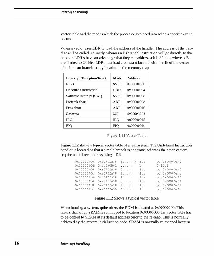
vector table and the modes which the processor is placed into when a specific event occurs.
When a vector uses LDR to load the address of the handler. The address of the han-dler will be called indirectly, whereas a B (branch) instruction will go directly to the handler. LDR’s have an advantage that they can address a full 32 bits, whereas B are limited to 24 bits. LDR must load a constant located within a 4k of the vector table but can branch to any location in the memory map.
Figure 1.11 Vector Table
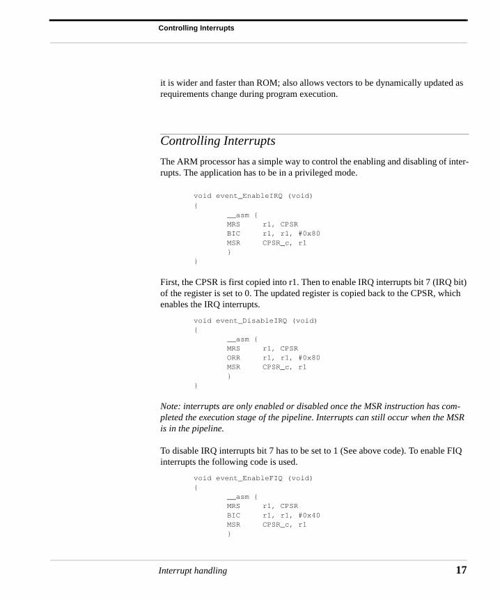
Figure 1.12 shows a typical vector table of a real system. The Undefined Instruction handler is located so that a simple branch is adequate, whereas the other vectors require an indirect address using LDR.
0x00000000: 0xe59ffa38 8... : > ldr pc,0x00000a40 0x00000004: 0xea000502 .... : b 0x1414 0x00000008: 0xe59ffa38 8... : ldr pc,0x00000a48 0x0000000c: 0xe59ffa38 8... : ldr pc,0x00000a4c 0x00000010: 0xe59ffa38 8... : ldr pc,0x00000a50 0x00000014: 0xe59ffa38 8... : ldr pc,0x00000a54
0x00000018: 0xe59ffa38 8... : ldr pc,0x00000a580x0000001c: 0xe59ffa38 8... : ldr pc,0x00000a5c
Figure 1.12 Shows a typical vector table
When booting a system, quite often, the ROM is located at 0x00000000. This means that when SRAM is re-mapped to location 0x00000000 the vector table has to be copied to SRAM at its default address prior to the re-map. This is normally achieved by the system initialization code. SRAM is normally re-mapped because
Interrupt/Exception/Reset Mode Address
Reset SVC 0x00000000
Undefined instruction UND 0x00000004
Software interrupt (SWI) SVC 0x00000008
Prefetch abort ABT 0x0000000c
Data abort ABT 0x00000010
Reserved N/A 0x00000014
IRQ IRQ 0x00000018
FIQ FIQ 0x0000001c
Interrupt handling
Controlling Interrupts
it is wider and faster than ROM; also allows vectors to be dynamically updated as requirements change during program execution.
Controlling Interrupts
The ARM processor has a simple way to control the enabling and disabling of inter-rupts. The application has to be in a privileged mode.
void event_EnableIRQ (void)
{__asm {
MRS r1, CPSR BIC r1, r1, #0x80 MSR CPSR_c, r1
}}
First, the CPSR is first copied into r1. Then to enable IRQ interrupts bit 7 (IRQ bit) of the register is set to 0. The updated register is copied back to the CPSR, which enables the IRQ interrupts.
void event_DisableIRQ (void){
__asm {MRS r1, CPSR
ORR r1, r1, #0x80 MSR CPSR_c, r1
}}
Note: interrupts are only enabled or disabled once the MSR instruction has com-pleted the execution stage of the pipeline. Interrupts can still occur when the MSR is in the pipeline.
To disable IRQ interrupts bit 7 has to be set to 1 (See above code). To enable FIQ interrupts the following code is used.
void event_EnableFIQ (void){
__asm { MRS r1, CPSR BIC r1, r1, #0x40 MSR CPSR_c, r1
}
Interrupt handling 17
Interrupt handling
18
}
Enabling FIQ interrupts is similar to enabling the IRQ interrupts except that bit 6 of the CPSR is manipulated. To disable FIQ interrupts the following inline assembler code should be used. Once the IRQ and FIQ bits are set to 0 (enabling interrupts) the core will not be able to masked out an interrupt.
void event_DisableFIQ (void)
{__asm {MRS r1, CPSR
ORR r1, r1, #0x40 MSR CPSR_c, r1
}}
These functions could be called by a SWI handler; the processor would therefore be in ARM state and in a privileged mode (SVC).
Note: there are no instructions to read or write to the CPSR in Thumb state. To manipulate the CPSR the processor has to be placed into ARM state.
Returning from an interrupt handler
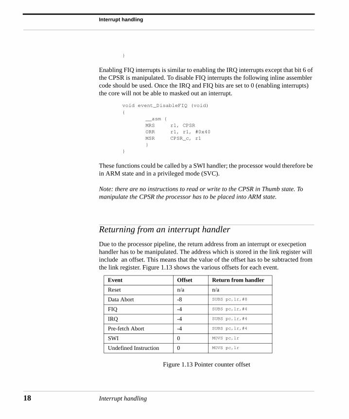
Due to the processor pipeline, the return address from an interrupt or execpetion handler has to be manipulated. The address which is stored in the link register will include an offset. This means that the value of the offset has to be subtracted from the link register. Figure 1.13 shows the various offsets for each event.
Figure 1.13 Pointer counter offset
Event Offset Return from handler
Reset n/a n/a
Data Abort -8 SUBS pc,lr,#8
FIQ -4 SUBS pc,lr,#4
IRQ -4 SUBS pc,lr,#4
Pre-fetch Abort -4 SUBS pc,lr,#4
SWI 0 MOVS pc,lr
Undefined Instruction 0 MOVS pc,lr
Interrupt handling
Returning from an interrupt handler
Note: the Data Abort is -8 indicating that the return address will be the original instruction that caused the Data Abort.
For an interrupt a typical method of return is to use the following instruction:
SUBS pc, r14, #4
The ‘S’ at the end of the instruction indicates that the destination register is the PC and that the CPSR is automatically updated. The #4 is due to the fact that both the IRQ and FIQ handlers must return one instruction before the instruction pointed to by the link register.
Another method, which is more widely used is to subtract 4 from the link register at the beginning of the handler. For example:
SUB lr,lr #4<handler code>MOVS pc,lr
And then finally, lr is copied into the PC and the CPSR is updated. An alternative approach, which will be described later in this chapter, is to :-
On entry:
SUB lr,lr,#4 ; adjust lrSTMFD sp_irq!,{r0-r3,lr} ; working registers<handler code>
On exit:
LDMFD sp_irq!,{r0-r3,pc}^ ; restore registers
Note: ^ in this context means restore CPSR from SPSR
Interrupt handling 19
Interrupt handling
20
Setting up the interrupt stacks
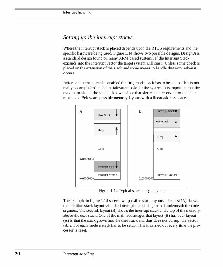
Where the interrupt stack is placed depends upon the RTOS requirements and the specific hardware being used. Figure 1.14 shows two possible designs. Design A is a standard design found on many ARM based systems. If the Interrupt Stack expands into the Interrupt vector the target system will crash. Unless some check is placed on the extension of the stack and some means to handle that error when it occurs.
Before an interrupt can be enabled the IRQ mode stack has to be setup. This is nor-mally accomplished in the initialization code for the system. It is important that the maximum size of the stack is known, since that size can be reserved for the inter-rupt stack. Below are possible memory layouts with a linear address space.
Figure 1.14 Typical stack design layouts
The example in figure 1.14 shows two possible stack layouts. The first (A) shows the tradition stack layout with the interrupt stack being stored underneath the code segment. The second, layout (B) shows the interrupt stack at the top of the memory above the user stack. One of the main advantages that layout (B) has over layout (A) is that the stack grows into the user stack and thus does not corrupt the vector table. For each mode a stack has to be setup. This is carried out every time the pro-cessor is reset.
User Stack
Heap
Code
Interrupt Vectors
Interrupt Stack
0x00000000
0x00008000
User Stack
Code
Interrupt Vectors
Interrupt Stack
0x00000000
Heap
A. B.
Interrupt handling
Setting up the interrupt stacks
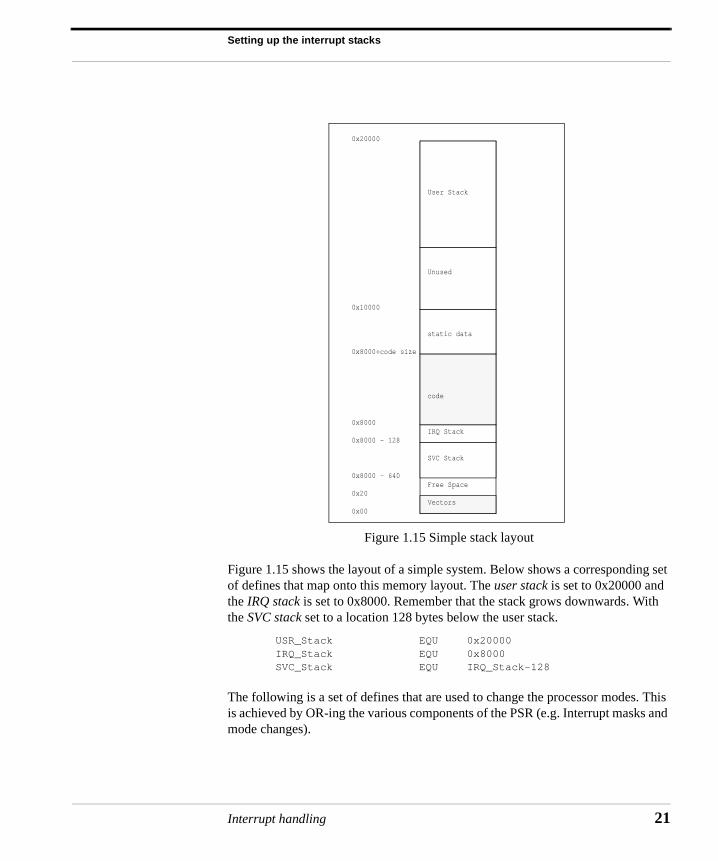
Figure 1.15 Simple stack layout
Figure 1.15 shows the layout of a simple system. Below shows a corresponding set of defines that map onto this memory layout. The user stack is set to 0x20000 and the IRQ stack is set to 0x8000. Remember that the stack grows downwards. With the SVC stack set to a location 128 bytes below the user stack.
USR_Stack EQU 0x20000IRQ_Stack EQU 0x8000SVC_Stack EQU IRQ_Stack-128
The following is a set of defines that are used to change the processor modes. This is achieved by OR-ing the various components of the PSR (e.g. Interrupt masks and mode changes).
Vectors
Free Space
SVC Stack
IRQ Stack
code
static data
Unused
User Stack
0x20000
0x10000
0x8000+code size
0x8000
0x8000 - 128
0x8000 - 640
0x20
0x00
Interrupt handling 21
Interrupt handling
22
Usr32md EQU 0x10FIQ32md EQU 0x11IRQ32md EQU 0x12SVC32md EQU 0x13Abt32md EQU 0x17Und32md EQU 0x1b
The following define is useful since it can be used to disable both IRQ and FIQ interrupts:
NoInt EQU 0xc0
The initialization code is required to set up the stack register for each processor mode used. The below code assumes that the processor is in SVC mode. The stack register, which is normally r13, is one of the registers that is always banked when a mode change occurs (see figure 1.7). The code below first shows how to initialize the IRQ stack. For safety reasons, it is best to always make sure that interrupts are disabled.
MOV r2, #NoInt|IRQ32md MSR CPSR_c, r2LDR sp_irq, =IRQ_NewStack:
IRQ_NewStackDCD IRQ_Stack
Similarly for setting up SVC stack the CPSR has to be manipulated to force the pro-cessor into SVC mode to gain access to the banked stack register r13_svc.
MOV r2, #NoInt|SVC32md MSR CPSR_c, r2LDR r13_svc, =SVC_NewStack :
SVC_NewStackDCD SVC_Stack
Lastly the user stack register needs to be setup. Once in user mode the processor cannot be forced into any other mode since User mode has no privileges to write to the CPSR (alternatively the processor can be put into System mode to setup the User mode stack).
MOV r2, #Usr32mdMSR CPSR_c, r2LDR r13_usr, =USR_NewStack:
USR_NewStackDCD USR_Stack
Interrupt handling
Installing and chaining interrupt handlers
The above method uses separate stacks for each mode rather than processing using a single stack. This has a number of advantages:
• If a single task corrupts the stack then the whole system would become unsta-ble. Using separate stacks allows for the possible debugging and isolation of an errant task/s.
• It reduces stack memory requirements. If interrupts are serviced on the task’s stack then separate space must be reserved on each task’s stack to handle the interrupt.
Installing and chaining interrupt handlers
For ROM and/or FlashROM based systems the vector table can be fixed without requiring installation. These systems tend to copy the complete vector table as a block from ROM to RAM without requiring the installation of individual vectors. This technique is normally used in the initialization stage since the memory tends to be re-mapped.
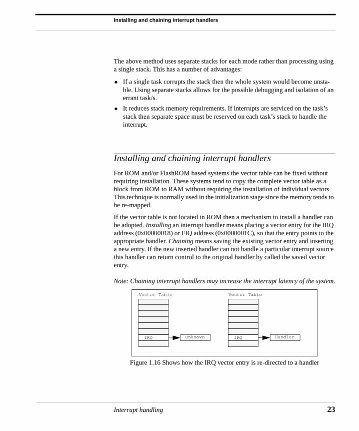
If the vector table is not located in ROM then a mechanism to install a handler can be adopted. Installing an interrupt handler means placing a vector entry for the IRQ address (0x00000018) or FIQ address (0x0000001C), so that the entry points to the appropriate handler. Chaining means saving the existing vector entry and inserting a new entry. If the new inserted handler can not handle a particular interrupt source this handler can return control to the original handler by called the saved vector entry.
Note: Chaining interrupt handlers may increase the interrupt latency of the system.
Figure 1.16 Shows how the IRQ vector entry is re-directed to a handler
IRQ unknown
Vector Table
IRQ Handler
Vector Table
Interrupt handling 23
Interrupt handling
24
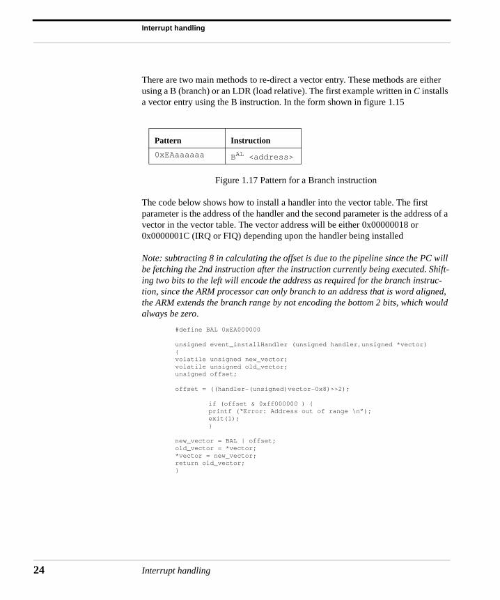
There are two main methods to re-direct a vector entry. These methods are either using a B (branch) or an LDR (load relative). The first example written in C installs a vector entry using the B instruction. In the form shown in figure 1.15
Figure 1.17 Pattern for a Branch instruction
The code below shows how to install a handler into the vector table. The first parameter is the address of the handler and the second parameter is the address of a vector in the vector table. The vector address will be either 0x00000018 or 0x0000001C (IRQ or FIQ) depending upon the handler being installed
Note: subtracting 8 in calculating the offset is due to the pipeline since the PC will be fetching the 2nd instruction after the instruction currently being executed. Shift-ing two bits to the left will encode the address as required for the branch instruc-tion, since the ARM processor can only branch to an address that is word aligned, the ARM extends the branch range by not encoding the bottom 2 bits, which would always be zero.
#define BAL 0xEA000000
unsigned event_installHandler (unsigned handler,unsigned *vector){volatile unsigned new_vector;volatile unsigned old_vector;unsigned offset;
offset = ((handler-(unsigned)vector-0x8)>>2);
if (offset & 0xff000000 ) {printf (“Error: Address out of range \n”);exit(1);}
new_vector = BAL | offset;old_vector = *vector;*vector = new_vector;return old_vector;}
Pattern Instruction
0xEAaaaaaa BAL <address>
Interrupt handling
Installing and chaining interrupt handlers
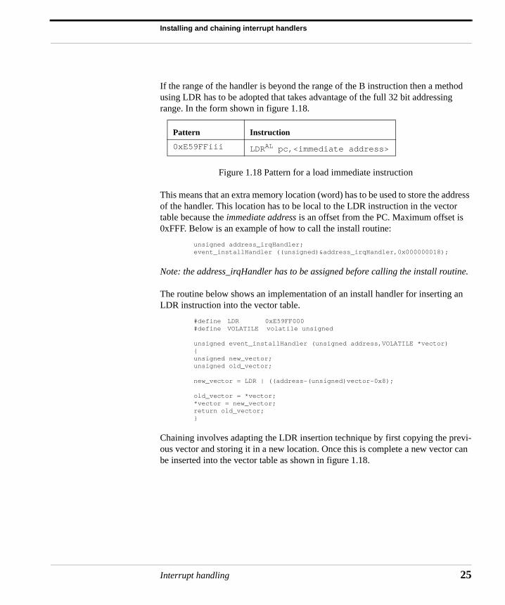
If the range of the handler is beyond the range of the B instruction then a method using LDR has to be adopted that takes advantage of the full 32 bit addressing range. In the form shown in figure 1.18.
Figure 1.18 Pattern for a load immediate instruction
This means that an extra memory location (word) has to be used to store the address of the handler. This location has to be local to the LDR instruction in the vector table because the immediate address is an offset from the PC. Maximum offset is 0xFFF. Below is an example of how to call the install routine:
unsigned address_irqHandler; event_installHandler ((unsigned)&address_irqHandler,0x000000018);
Note: the address_irqHandler has to be assigned before calling the install routine.
The routine below shows an implementation of an install handler for inserting an LDR instruction into the vector table.
#define LDR 0xE59FF000#define VOLATILE volatile unsigned
unsigned event_installHandler (unsigned address,VOLATILE *vector){unsigned new_vector;unsigned old_vector;
new_vector = LDR | ((address-(unsigned)vector-0x8);
old_vector = *vector;*vector = new_vector;return old_vector;}
Chaining involves adapting the LDR insertion technique by first copying the previ-ous vector and storing it in a new location. Once this is complete a new vector can be inserted into the vector table as shown in figure 1.18.
Pattern Instruction
0xE59FFiii LDRAL pc,<immediate address>
Interrupt handling 25
Interrupt handling
26
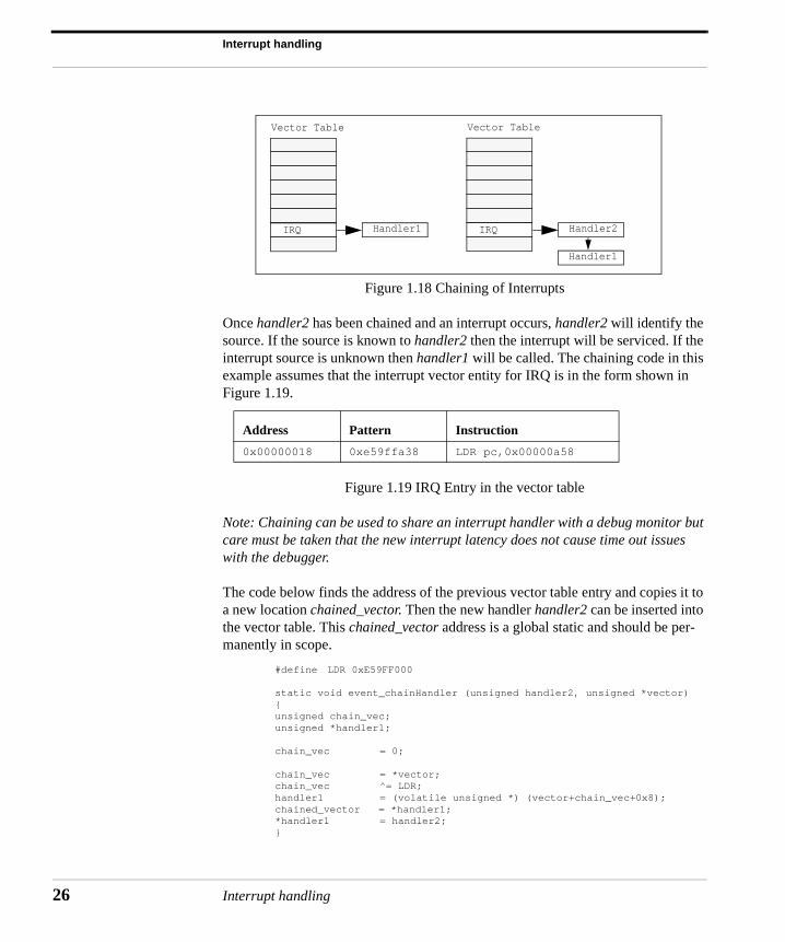
Figure 1.18 Chaining of Interrupts
Once handler2 has been chained and an interrupt occurs, handler2 will identify the source. If the source is known to handler2 then the interrupt will be serviced. If the interrupt source is unknown then handler1 will be called. The chaining code in this example assumes that the interrupt vector entity for IRQ is in the form shown in Figure 1.19.
Figure 1.19 IRQ Entry in the vector table
Note: Chaining can be used to share an interrupt handler with a debug monitor but care must be taken that the new interrupt latency does not cause time out issues with the debugger.
The code below finds the address of the previous vector table entry and copies it to a new location chained_vector. Then the new handler handler2 can be inserted into the vector table. This chained_vector address is a global static and should be per-manently in scope.
#define LDR 0xE59FF000
static void event_chainHandler (unsigned handler2, unsigned *vector) {unsigned chain_vec;unsigned *handler1;
chain_vec = 0; chain_vec = *vector;
chain_vec ^= LDR; handler1 = (volatile unsigned *) (vector+chain_vec+0x8);
chained_vector = *handler1; *handler1 = handler2;
}
Address Pattern Instruction
0x00000018 0xe59ffa38 LDR pc,0x00000a58
IRQ Handler1
Vector Table
IRQ Handler2
Vector Table
Handler1
Interrupt handling
Simple non-nested interrupt handler
Simple non-nested interrupt handler
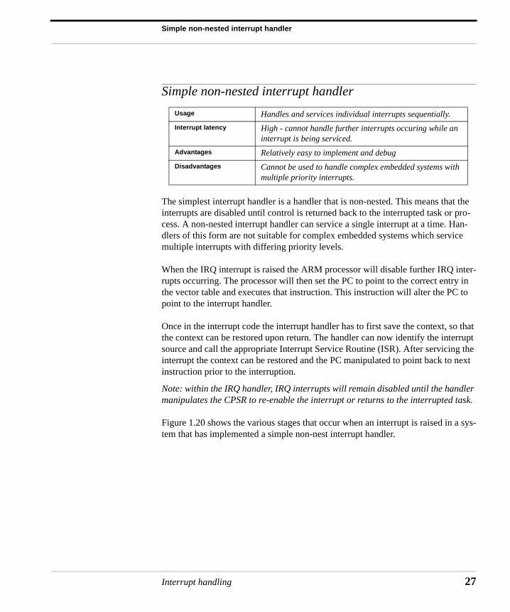
The simplest interrupt handler is a handler that is non-nested. This means that the interrupts are disabled until control is returned back to the interrupted task or pro-cess. A non-nested interrupt handler can service a single interrupt at a time. Han-dlers of this form are not suitable for complex embedded systems which service multiple interrupts with differing priority levels.
When the IRQ interrupt is raised the ARM processor will disable further IRQ inter-rupts occurring. The processor will then set the PC to point to the correct entry in the vector table and executes that instruction. This instruction will alter the PC to point to the interrupt handler.
Once in the interrupt code the interrupt handler has to first save the context, so that the context can be restored upon return. The handler can now identify the interrupt source and call the appropriate Interrupt Service Routine (ISR). After servicing the interrupt the context can be restored and the PC manipulated to point back to next instruction prior to the interruption.
Note: within the IRQ handler, IRQ interrupts will remain disabled until the handler manipulates the CPSR to re-enable the interrupt or returns to the interrupted task.
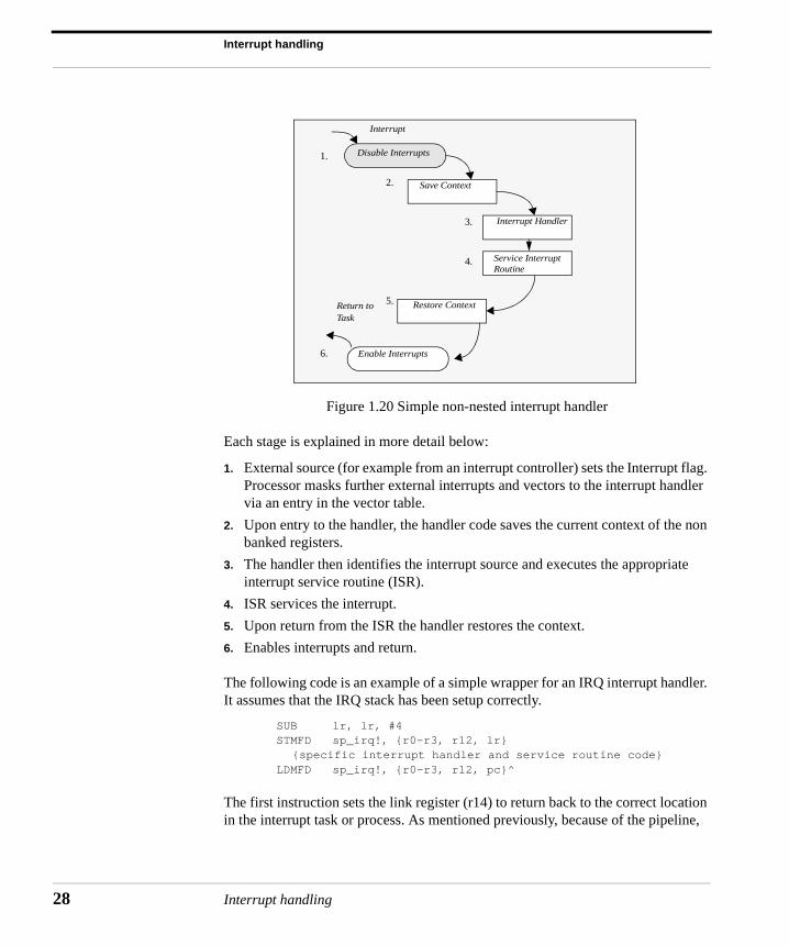
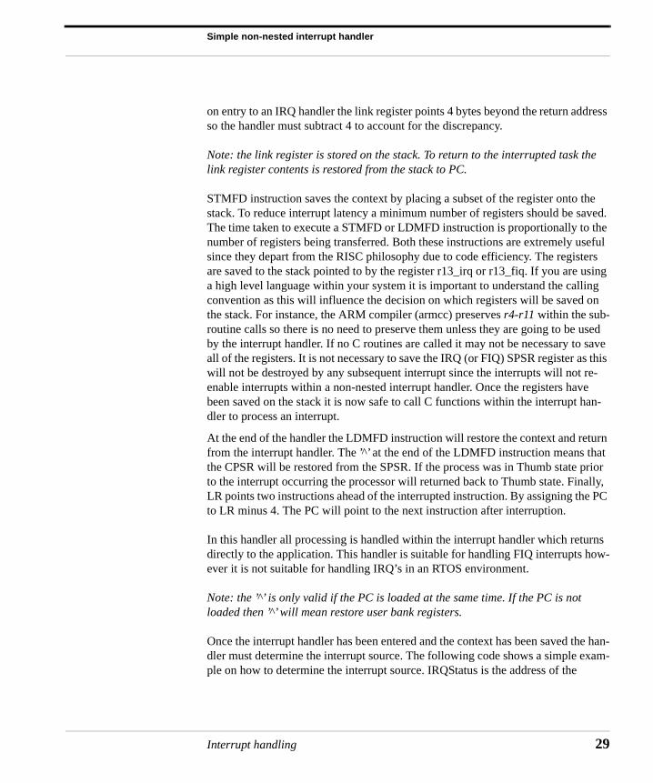
Figure 1.20 shows the various stages that occur when an interrupt is raised in a sys-tem that has implemented a simple non-nest interrupt handler.
Usage Handles and services individual interrupts sequentially.
Interrupt latency High - cannot handle further interrupts occuring while an interrupt is being serviced.
Advantages Relatively easy to implement and debug
Disadvantages Cannot be used to handle complex embedded systems with multiple priority interrupts.
Interrupt handling 27
Interrupt handling
28
Figure 1.20 Simple non-nested interrupt handler
Each stage is explained in more detail below:
1. External source (for example from an interrupt controller) sets the Interrupt flag. Processor masks further external interrupts and vectors to the interrupt handler via an entry in the vector table.
2. Upon entry to the handler, the handler code saves the current context of the non banked registers.
3. The handler then identifies the interrupt source and executes the appropriate interrupt service routine (ISR).
4. ISR services the interrupt.
5. Upon return from the ISR the handler restores the context.
6. Enables interrupts and return.
The following code is an example of a simple wrapper for an IRQ interrupt handler. It assumes that the IRQ stack has been setup correctly.
SUB lr, lr, #4STMFD sp_irq!, {r0-r3, r12, lr}
{specific interrupt handler and service routine code} LDMFD sp_irq!, {r0-r3, r12, pc}^
The first instruction sets the link register (r14) to return back to the correct location in the interrupt task or process. As mentioned previously, because of the pipeline,
Disable Interrupts
Save Context
Interrupt Handler
Restore Context
Enable Interrupts
Interrupt
Return toTask
Service InterruptRoutine
1.
2.
3.
4.
5.
6.
Interrupt handling
Simple non-nested interrupt handler
on entry to an IRQ handler the link register points 4 bytes beyond the return address so the handler must subtract 4 to account for the discrepancy.
Note: the link register is stored on the stack. To return to the interrupted task the link register contents is restored from the stack to PC.
STMFD instruction saves the context by placing a subset of the register onto the stack. To reduce interrupt latency a minimum number of registers should be saved. The time taken to execute a STMFD or LDMFD instruction is proportionally to the number of registers being transferred. Both these instructions are extremely useful since they depart from the RISC philosophy due to code efficiency. The registers are saved to the stack pointed to by the register r13_irq or r13_fiq. If you are using a high level language within your system it is important to understand the calling convention as this will influence the decision on which registers will be saved on the stack. For instance, the ARM compiler (armcc) preserves r4-r11 within the sub-routine calls so there is no need to preserve them unless they are going to be used by the interrupt handler. If no C routines are called it may not be necessary to save all of the registers. It is not necessary to save the IRQ (or FIQ) SPSR register as this will not be destroyed by any subsequent interrupt since the interrupts will not re-enable interrupts within a non-nested interrupt handler. Once the registers have been saved on the stack it is now safe to call C functions within the interrupt han-dler to process an interrupt.
At the end of the handler the LDMFD instruction will restore the context and return from the interrupt handler. The ’̂ ’ at the end of the LDMFD instruction means that the CPSR will be restored from the SPSR. If the process was in Thumb state prior to the interrupt occurring the processor will returned back to Thumb state. Finally, LR points two instructions ahead of the interrupted instruction. By assigning the PC to LR minus 4. The PC will point to the next instruction after interruption.
In this handler all processing is handled within the interrupt handler which returns directly to the application. This handler is suitable for handling FIQ interrupts how-ever it is not suitable for handling IRQ’s in an RTOS environment.
Note: the ’̂ ’ is only valid if the PC is loaded at the same time. If the PC is not loaded then ’̂ ’ will mean restore user bank registers.
Once the interrupt handler has been entered and the context has been saved the han-dler must determine the interrupt source. The following code shows a simple exam-ple on how to determine the interrupt source. IRQStatus is the address of the
Interrupt handling 29
Interrupt handling
30
interrupt status register. If the interrupt source is not determined then control is passed to the chained debug monitor handler.
LDR r0, IRQStatus LDR r0, [r0]TST r0, #0x0080BNE timer_isr TST r0, #0x0001BNE button_isrLDMFD sp!, {r0 - r3, lr}LDR pc, debug_monitor
Nested interrupt handler
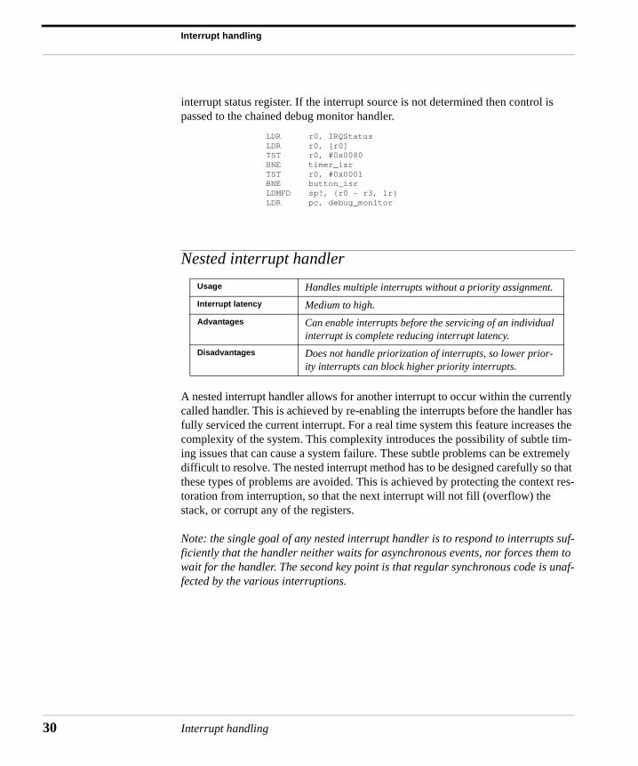
A nested interrupt handler allows for another interrupt to occur within the currently called handler. This is achieved by re-enabling the interrupts before the handler has fully serviced the current interrupt. For a real time system this feature increases the complexity of the system. This complexity introduces the possibility of subtle tim-ing issues that can cause a system failure. These subtle problems can be extremely difficult to resolve. The nested interrupt method has to be designed carefully so that these types of problems are avoided. This is achieved by protecting the context res-toration from interruption, so that the next interrupt will not fill (overflow) the stack, or corrupt any of the registers.
Note: the single goal of any nested interrupt handler is to respond to interrupts suf-ficiently that the handler neither waits for asynchronous events, nor forces them to wait for the handler. The second key point is that regular synchronous code is unaf-fected by the various interruptions.
Usage Handles multiple interrupts without a priority assignment.
Interrupt latency Medium to high.
Advantages Can enable interrupts before the servicing of an individual interrupt is complete reducing interrupt latency.
Disadvantages Does not handle priorization of interrupts, so lower prior-ity interrupts can block higher priority interrupts.
Interrupt handling
Nested interrupt handler
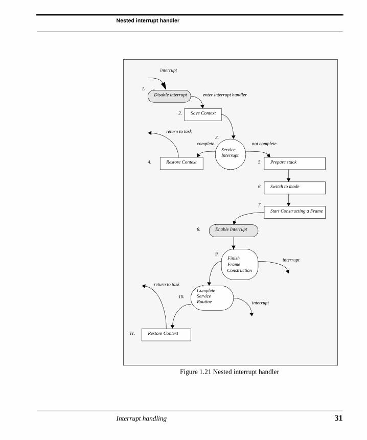
Figure 1.21 Nested interrupt handler
interrupt
Disable interrupt
Save Context
ServiceInterrupt
Restore Context
Switch to mode
Start Constructing a Frame
Enable Interrupt
FinishFrameConstruction
CompleteService Routine
Restore Context
return to task
interrupt
interrupt
Prepare stack
enter interrupt handler
return to task
complete not complete
1.
2.
3.
4. 5.
6.
7.
8.
9.
10.
11.
Interrupt handling 31
Interrupt handling
32
Due to an increase in complexity, there are many standard problems that can be observed if nested interrupts are supported. One of the main problems is a race con-dition where a cascade of interrupts occur. This will cause a continuous interruption of the handler until either the interrupt stack was full (overflowing) or the registers were corrupted. A designer has to balance efficiency with safety. This involves using a defensive coding style that assumes problems will occur. The system should check the stack and protect against register corruption where possible.
Figure 1.21 shows a nested interrupt handler. As can been seen from the diagram the handler is quite a bit more complicated than the simple non-nested interrupt handler described in the previous section.
How stacks are organized is one of the first decisions a designer has to make when designing a nested interrupt handler. There are two fundamental methods that can be adopted. The first uses a single stack and the second uses multiple stacks. The multiple stack method uses a stack for each interrupt and/or service routine. Having multiple stacks increases the execution time and complexity of the handler. For a time critical system these tend to be undesirable characteristics.
The nested interrupt handler entry code is identical to the simple non-nested inter-rupt handler, except on exit, the handler tests a flag which is updated by the ISR. The flag indicates whether further processing is required. If further processing is not required then the service routine is complete and the handler can exit. If further processing is required the handler may take several actions; re-enabling interrupts and/or perform a context switch.
Re-enabling interrupts involves switching out of IRQ mode (typically to SVC mode or SYSTEM mode). We cannot simply re-enable interrupts in IRQ mode as this would lead to the link register (lr_irq) being corrupted if an interrupt occurred after a branch with link (BL) instruction. This problem will be discussed in more detail in the next section called Re-entrant interrupt handler.
As a side note, performing a context switch involves flattening (empting) the IRQ stack as the handler should not perform a context switch while there is data on the IRQ stack unless the handler can maintain a separate IRQ stack for each task which is as mentioned previously undesirable. All registers saved on the IRQ stack must be transferred to the task’s stack (typically the SVC stack). The remaining registers must then be saved on the task stack. This is transferred to a reserved block on the stack called a stack frame.
Interrupt handling
Nested interrupt handler
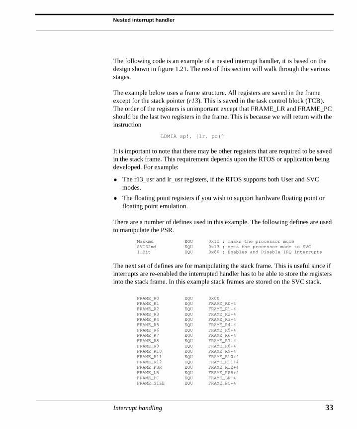
The following code is an example of a nested interrupt handler, it is based on the design shown in figure 1.21. The rest of this section will walk through the various stages.
The example below uses a frame structure. All registers are saved in the frame except for the stack pointer (r13). This is saved in the task control block (TCB). The order of the registers is unimportant except that FRAME_LR and FRAME_PC should be the last two registers in the frame. This is because we will return with the instruction
LDMIA sp!, {lr, pc}^
It is important to note that there may be other registers that are required to be saved in the stack frame. This requirement depends upon the RTOS or application being developed. For example:
• The r13_usr and lr_usr registers, if the RTOS supports both User and SVC modes.
• The floating point registers if you wish to support hardware floating point or floating point emulation.
There are a number of defines used in this example. The following defines are used to manipulate the PSR.
Maskmd EQU 0x1f ; masks the processor modeSVC32md EQU 0x13 ; sets the processor mode to SVCI_Bit EQU 0x80 ; Enables and Disable IRQ interrupts
The next set of defines are for manipulating the stack frame. This is useful since if interrupts are re-enabled the interrupted handler has to be able to store the registers into the stack frame. In this example stack frames are stored on the SVC stack.
FRAME_R0 EQU 0x00FRAME_R1 EQU FRAME_R0+4FRAME_R2 EQU FRAME_R1+4FRAME_R3 EQU FRAME_R2+4FRAME_R4 EQU FRAME_R3+4FRAME_R5 EQU FRAME_R4+4FRAME_R6 EQU FRAME_R5+4FRAME_R7 EQU FRAME_R6+4FRAME_R8 EQU FRAME_R7+4FRAME_R9 EQU FRAME_R8+4FRAME_R10 EQU FRAME_R9+4FRAME_R11 EQU FRAME_R10+4FRAME_R12 EQU FRAME_R11+4FRAME_PSR EQU FRAME_R12+4FRAME_LR EQU FRAME_PSR+4FRAME_PC EQU FRAME_LR+4FRAME_SIZE EQU FRAME_PC+4
Interrupt handling 33
Interrupt handling
34
The entry point for the handler (again this is for an IRQ handler) is the same code as the simple non-nested interrupt handler. The link register is set to point to the cor-rect instruction and the context is saved on to the IRQ stack (r13_irq/sp_irq).
The interrupt service code, after the entry point, services the interrupt. Once com-plete or partially complete control is passed back to the handler, which then calls the subroutine read_RescheduleFlag. The read_RescheduleFlag routine then deter-mines whether further processing is required. It returns a non-zero value in r0 if no further processing is required, otherwise it returns 0.
The return flag in r0 is then tested and if not equal to 0 the handler restore context and then returns control back to the halted task.
If r0 is set to 0, indicating that further processing is required. The first operation is to save the spsr, so a copy of the spsr_irq is moved into r2. SPSR can then be stored in the stack frame by the handler later on in the code.
Then the IRQ stack address (sp_irq) is copied into r0 for use later. The next step is to flatten (empty) the IRQ stack. This is done by adding 6*4 bytes to the stack. Note that since the stack grows downwards, the ADD operation will reset the stack. The handler does not need to worry about the data on the IRQ stack being corrupted by another nested interrupt, as interrupts are still disabled and the handler will not re-enable the interrupts until the data on the IRQ stack has been recovered.
The handler then switches to SVC mode, interrupts are still disabled. The cpsr is copied to r1 and modified to set SVC mode. r1 is then written back to the cpsr and
2IRQ IRQ_Entry SUB lr_irq, lr_irq, #4 STMDB sp_irq!, {r0-r3, r12, lr_irq} : <interrupt service code>
3IRQ BL read_RescheduleFlag
3IRQ CMP r0, #0
4IRQ LDMNEIA sp_irq!, {r0-r3, r12, pc}^
5IRQ MRS r2, spsr_irq
5IRQ MOV r0, sp_irqADD sp_irq, sp_irq, #6*4
Interrupt handling
Nested interrupt handler
the current mode changes to SVC mode. A copy of the new cpsr is left in r1 for later use.
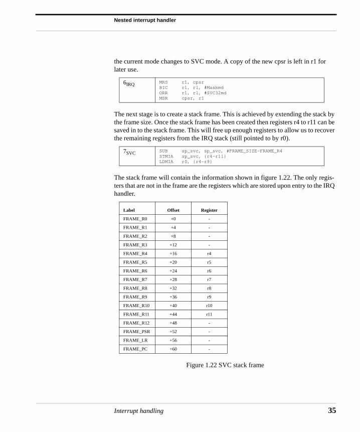
The next stage is to create a stack frame. This is achieved by extending the stack by the frame size. Once the stack frame has been created then registers r4 to r11 can be saved in to the stack frame. This will free up enough registers to allow us to recover the remaining registers from the IRQ stack (still pointed to by r0).
The stack frame will contain the information shown in figure 1.22. The only regis-ters that are not in the frame are the registers which are stored upon entry to the IRQ handler.
Figure 1.22 SVC stack frame
6IRQ MRS r1, cpsrBIC r1, r1, #MaskmdORR r1, r1, #SVC32mdMSR cpsr, r1
7SVC SUB sp_svc, sp_svc, #FRAME_SIZE-FRAME_R4STMIA sp_svc, {r4-r11}LDMIA r0, {r4-r9}
Label Offset Register
FRAME_R0 +0 -
FRAME_R1 +4 -
FRAME_R2 +8 -
FRAME_R3 +12 -
FRAME_R4 +16 r4
FRAME_R5 +20 r5
FRAME_R6 +24 r6
FRAME_R7 +28 r7
FRAME_R8 +32 r8
FRAME_R9 +36 r9
FRAME_R10 +40 r10
FRAME_R11 +44 r11
FRAME_R12 +48 -
FRAME_PSR +52 -
FRAME_LR +56 -
FRAME_PC +60 -
Interrupt handling 35
Interrupt handling
36
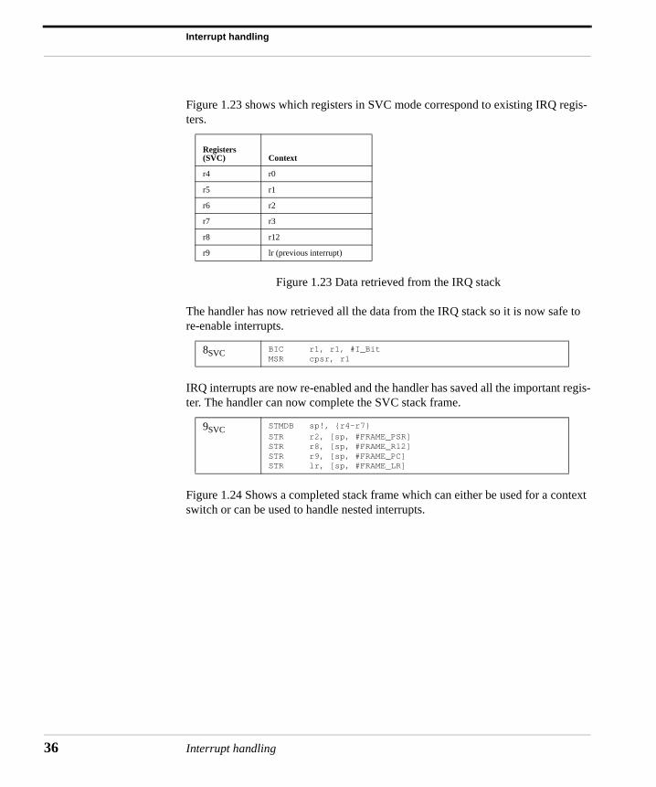
Figure 1.23 shows which registers in SVC mode correspond to existing IRQ regis-ters.
Figure 1.23 Data retrieved from the IRQ stack
The handler has now retrieved all the data from the IRQ stack so it is now safe to re-enable interrupts.
IRQ interrupts are now re-enabled and the handler has saved all the important regis-ter. The handler can now complete the SVC stack frame.
Figure 1.24 Shows a completed stack frame which can either be used for a context switch or can be used to handle nested interrupts.
Registers (SVC) Context
r4 r0
r5 r1
r6 r2
r7 r3
r8 r12
r9 lr (previous interrupt)
8SVC BIC r1, r1, #I_BitMSR cpsr, r1
9SVC STMDB sp!, {r4-r7} STR r2, [sp, #FRAME_PSR] STR r8, [sp, #FRAME_R12] STR r9, [sp, #FRAME_PC] STR lr, [sp, #FRAME_LR]
Interrupt handling
Nested interrupt handler
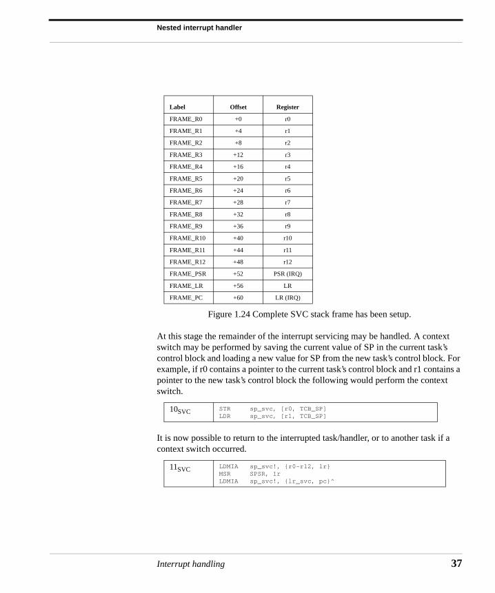
Figure 1.24 Complete SVC stack frame has been setup.
At this stage the remainder of the interrupt servicing may be handled. A context switch may be performed by saving the current value of SP in the current task’s control block and loading a new value for SP from the new task’s control block. For example, if r0 contains a pointer to the current task’s control block and r1 contains a pointer to the new task’s control block the following would perform the context switch.
It is now possible to return to the interrupted task/handler, or to another task if a context switch occurred.
Label Offset Register
FRAME_R0 +0 r0
FRAME_R1 +4 r1
FRAME_R2 +8 r2
FRAME_R3 +12 r3
FRAME_R4 +16 r4
FRAME_R5 +20 r5
FRAME_R6 +24 r6
FRAME_R7 +28 r7
FRAME_R8 +32 r8
FRAME_R9 +36 r9
FRAME_R10 +40 r10
FRAME_R11 +44 r11
FRAME_R12 +48 r12
FRAME_PSR +52 PSR (IRQ)
FRAME_LR +56 LR
FRAME_PC +60 LR (IRQ)
10SVC STR sp_svc, [r0, TCB_SP] LDR sp_svc, [r1, TCB_SP]
11SVC LDMIA sp_svc!, {r0-r12, lr} MSR SPSR, lr LDMIA sp_svc!, {lr_svc, pc}^
Interrupt handling 37
Interrupt handling
38
Re-entrant interrupt handler
A re-entrant interrupt handler is a method of handling multiple interrupts where interrupts are filtered by priority. This is important since there is a requirement that interrupts with higher priority have a lower latency. This type of filtering cannot be achieved using the conventional nested interrupt handler.
The basic difference between a re-entrant interrupt handler and a nested interrupt handler is that the interrupts are re-enabled early on in the interrupt handler to achieve low interrupt latency. There are a number of issues relating to re-enabling the interrupts early, which are described in more detail later in this section.
Note: all interrupts in a re-entrant interrupt handler must be serviced in SVC mode, System mode, or an Abort mode on the ARM processor.
If interrupts are re-enabled in an interrupt mode and the interrupt routine performs a BL (subroutine call) instruction, the subroutine return address will be set in the lr_irq register. This address would be subsequently destroyed by an interrupt, which would overwrite the return address into lr_irq register. To avoid this, the interrupt routine should swap into SVC mode or SYSTEM. The BL instruction can then use lr_svc register to store the subroutine address. The interrupts must be disabled at source by setting a bit in the interrupt controller before re-enabling interrupts via the CPSR.
If interrupts are re-enabled in the CPSR before processing is complete and the inter-rupt source is not disabled, an interrupt will be immediately re-generated leading to an infinite interrupt sequence or race condition. Most interrupt controllers have an interrupt mask register which allows you to mask out one or more interrupts leaving the remainder of the interrupts enabled.
Note: watchdog timers can be a useful method to reset a system that has gone into a race condition.
The interrupt stack is unused since interrupts are serviced in SVC mode (i.e. on the task’s stack). Instead the IRQ stack pointer (r13) is used to point to a 12 byte struc-ture which will be used to store some registers temporarily on interrupt entry. In the
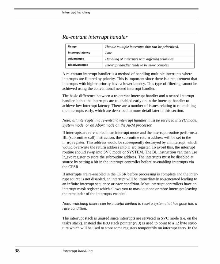
Usage Handle multiple interrupts that can be prioritized.
Interrupt latency Low
Advantages Handling of interrupts with differing priorities.
Disadvantages Interrupt handler tends to be more complex
Interrupt handling
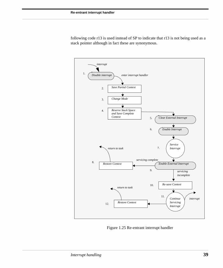
Re-entrant interrupt handler
following code r13 is used instead of SP to indicate that r13 is not being used as a stack pointer although in fact these are synonymous.
Figure 1.25 Re-entrant interrupt handler
interrupt
Disable interrupt
Save Partial Context
Enable Interrupt
Restore Context
enter interrupt handler
Change Mode
Reserve Stack Space
Clear External Interrupt
ServiceInterrupt
servicingincomplete
servicing complete
return to task
ContinueServicingInterrupt
Restore Context
return to task
interrupt
and Save CompleteContext
Enable External Interrupt
Re-save Context
1.
2.
3.
4.
5.
6.
7.
8.
9.
10.
11.
12.
Interrupt handling 39
Interrupt handling
40
It is paramount for a re-entrant interrupt handler to operate effectively that the inter-rupts be prioritized. If the interrupts are not prioritized the system latency degrades to that of a nested interrupt handler as lower priority interrupts will be able to pre-empt the servicing of a higher priority interrupt. This can lead to the locking out of higher priority interrupts for the duration of the servicing of a lower priority inter-rupt.
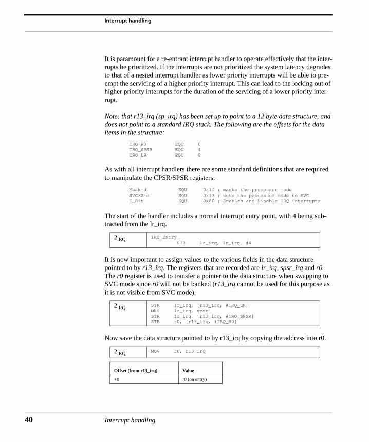
Note: that r13_irq (sp_irq) has been set up to point to a 12 byte data structure, and does not point to a standard IRQ stack. The following are the offsets for the data items in the structure:
IRQ_R0 EQU 0IRQ_SPSR EQU 4IRQ_LR EQU 8
As with all interrupt handlers there are some standard definitions that are required to manipulate the CPSR/SPSR registers:
Maskmd EQU 0x1f ; masks the processor modeSVC32md EQU 0x13 ; sets the processor mode to SVCI_Bit EQU 0x80 ; Enables and Disable IRQ interrupts
The start of the handler includes a normal interrupt entry point, with 4 being sub-tracted from the lr_irq.
It is now important to assign values to the various fields in the data structure pointed to by r13_irq. The registers that are recorded are lr_irq, spsr_irq and r0. The r0 register is used to transfer a pointer to the data structure when swapping to SVC mode since r0 will not be banked (r13_irq cannot be used for this purpose as it is not visible from SVC mode).
Now save the data structure pointed to by r13_irq by copying the address into r0.
2IRQ IRQ_Entry SUB lr_irq, lr_irq, #4
2IRQ STR lr_irq, [r13_irq, #IRQ_LR]MRS lr_irq, spsrSTR lr_irq, [r13_irq, #IRQ_SPSR]STR r0, [r13_irq, #IRQ_R0]
2IRQ MOV r0, r13_irq
Offset (from r13_irq) Value
+0 r0 (on entry)
Interrupt handling
Re-entrant interrupt handler
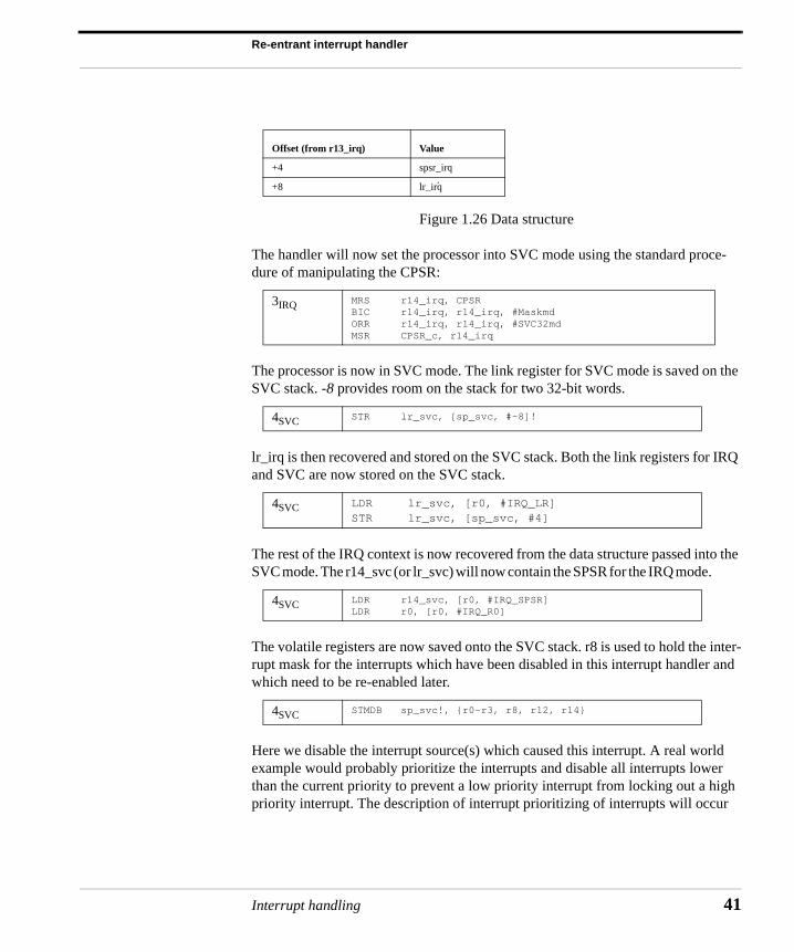
Figure 1.26 Data structure
The handler will now set the processor into SVC mode using the standard proce-dure of manipulating the CPSR:
The processor is now in SVC mode. The link register for SVC mode is saved on the SVC stack. -8 provides room on the stack for two 32-bit words.
lr_irq is then recovered and stored on the SVC stack. Both the link registers for IRQ and SVC are now stored on the SVC stack.
The rest of the IRQ context is now recovered from the data structure passed into the SVC mode. The r14_svc (or lr_svc) will now contain the SPSR for the IRQ mode.
The volatile registers are now saved onto the SVC stack. r8 is used to hold the inter-rupt mask for the interrupts which have been disabled in this interrupt handler and which need to be re-enabled later.
Here we disable the interrupt source(s) which caused this interrupt. A real world example would probably prioritize the interrupts and disable all interrupts lower than the current priority to prevent a low priority interrupt from locking out a high priority interrupt. The description of interrupt prioritizing of interrupts will occur
+4 spsr_irq
+8 lr_irq
3IRQ MRS r14_irq, CPSR BIC r14_irq, r14_irq, #MaskmdORR r14_irq, r14_irq, #SVC32mdMSR CPSR_c, r14_irq
4SVC STR lr_svc, [sp_svc, #-8]!
4SVC LDR lr_svc, [r0, #IRQ_LR]STR lr_svc, [sp_svc, #4]
4SVC LDR r14_svc, [r0, #IRQ_SPSR]LDR r0, [r0, #IRQ_R0]
4SVC STMDB sp_svc!, {r0-r3, r8, r12, r14}
Offset (from r13_irq) Value
.
Interrupt handling 41
Interrupt handling
42
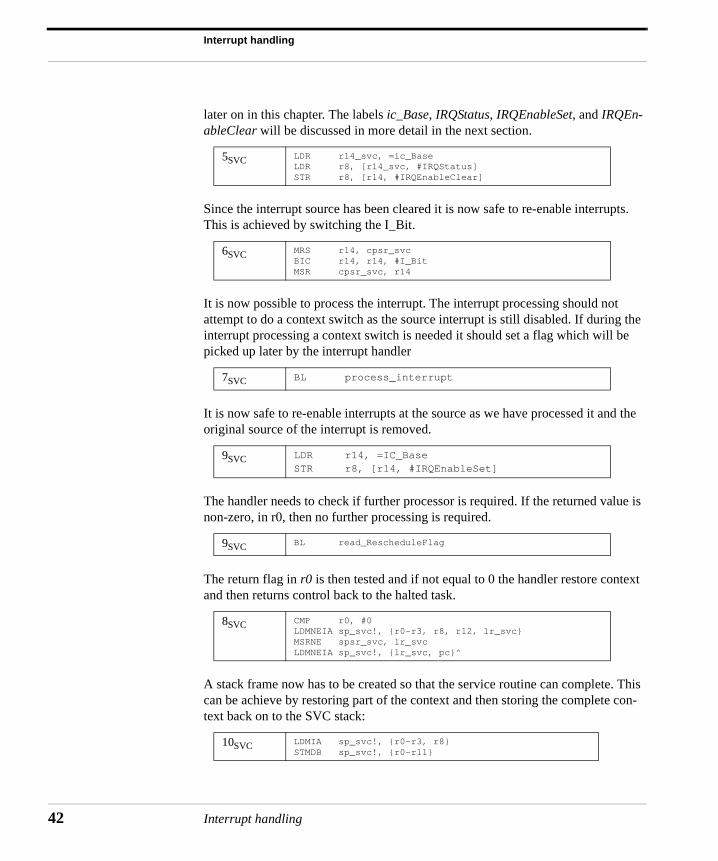
later on in this chapter. The labels ic_Base, IRQStatus, IRQEnableSet, and IRQEn-ableClear will be discussed in more detail in the next section.
Since the interrupt source has been cleared it is now safe to re-enable interrupts. This is achieved by switching the I_Bit.
It is now possible to process the interrupt. The interrupt processing should not attempt to do a context switch as the source interrupt is still disabled. If during the interrupt processing a context switch is needed it should set a flag which will be picked up later by the interrupt handler
It is now safe to re-enable interrupts at the source as we have processed it and the original source of the interrupt is removed.
The handler needs to check if further processor is required. If the returned value is non-zero, in r0, then no further processing is required.
The return flag in r0 is then tested and if not equal to 0 the handler restore context and then returns control back to the halted task.
A stack frame now has to be created so that the service routine can complete. This can be achieve by restoring part of the context and then storing the complete con-text back on to the SVC stack:
5SVC LDR r14_svc, =ic_BaseLDR r8, [r14_svc, #IRQStatus]STR r8, [r14, #IRQEnableClear]
6SVC MRS r14, cpsr_svcBIC r14, r14, #I_BitMSR cpsr_svc, r14
7SVC BL process_interrupt
9SVC LDR r14, =IC_BaseSTR r8, [r14, #IRQEnableSet]
9SVC BL read_RescheduleFlag
8SVC CMP r0, #0LDMNEIA sp_svc!, {r0-r3, r8, r12, lr_svc}MSRNE spsr_svc, lr_svcLDMNEIA sp_svc!, {lr_svc, pc}^
10SVC LDMIA sp_svc!, {r0-r3, r8}STMDB sp_svc!, {r0-r11}
Interrupt handling
Re-entrant interrupt handler
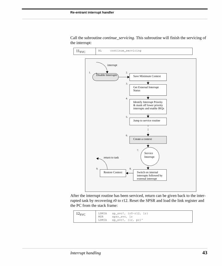
Call the subroutine continue_servicing. This subroutine will finish the servicing of the interrupt:
After the interrupt routine has been serviced, return can be given back to the inter-rupted task by recovering r0 to r12. Reset the SPSR and load the link register and the PC from the stack frame:
11SVC BL continue_servicing
12SVC LDMIA sp_svc!, {r0-r12, lr} MSR spsr_svc, lr LDMIA sp_svc!, {lr, pc}^
interrupt
Disable Interrupts Save Minimum Context
Get External InterruptStatus
Identify Interrupt Priority& mask off lower priorityinterrupts and enable IRQs
Jump to service routine
Service Interrupt
Create a context
Switch on internalinterrupts followed byexternal interrupt
Restore Context
return to task
1. 2.
3.
4.
5.
6.
7.
8.9.
Interrupt handling 43
Interrupt handling
44
Prioritized interrupt handler (1) - simple
The simple and nested interrupt handler services interrupts on a first-come-first-serve basis, whereas a prioritized interrupt handler will associate a priority level with a particular interrupt source. A priority level is used to dictate the order that the interrupts will be serviced. This means that a higher priority interrupt will take precedence over a lower priority interrupt, which is a desirable characteristic in an embedded system.
Methods of prioritization can either be achieved in hardware or software. Hardware prioritization means that the handler is simpler to design since the interrupt control-ler will provide the current highest priority interrupt that requires servicing. These systems require more initialization code at startup since the interrupts and associ-ated priority level tables have to be constructed before the system can be switched on. Software prioritization requires an external interrupt controller. This controller has to provide a minimal set of functions that include being able to set and unset masks and read interrupt status and source.
For software systems the rest of this section will describe a priority interrupt han-
dler and to help with this a fictional interrupt controller will be used. The interrupt controller takes in multiple interrupt sources and will generate an IRQ and/or FIQ signal depending upon whether a particular interrupt source is enabled or disabled.
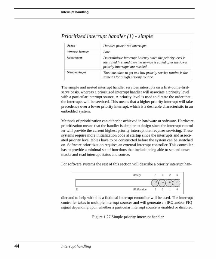
Figure 1.27 Simple priority interrupt handler
Usage Handles prioritized interrupts.
Interrupt latency Low
Advantages Deterministic Interrupt Latency since the priority level is identified first and then the service is called after the lower priority interrupts are masked.
Disadvantages The time taken to get to a low priority service routine is the same as for a high priority routine.
t1txrxt2
8 4 2 u
3 2 1 031
Binary
Bit Position
Interrupt handling
Prioritized interrupt handler (1) - simple
Figure 1.27 show a diagram of a priority interrupt handler it is similar to the re-entrant interrupt handler.
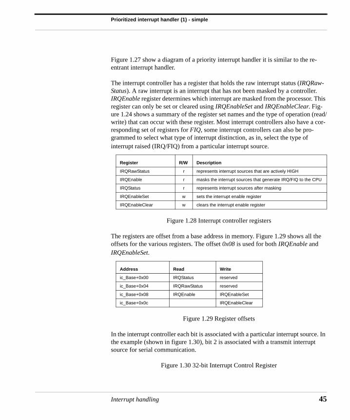
The interrupt controller has a register that holds the raw interrupt status (IRQRaw-Status). A raw interrupt is an interrupt that has not been masked by a controller. IRQEnable register determines which interrupt are masked from the processor. This register can only be set or cleared using IRQEnableSet and IRQEnableClear. Fig-ure 1.24 shows a summary of the register set names and the type of operation (read/write) that can occur with these register. Most interrupt controllers also have a cor-responding set of registers for FIQ, some interrupt controllers can also be pro-grammed to select what type of interrupt distinction, as in, select the type of interrupt raised (IRQ/FIQ) from a particular interrupt source.
Figure 1.28 Interrupt controller registers
The registers are offset from a base address in memory. Figure 1.29 shows all the offsets for the various registers. The offset 0x08 is used for both IRQEnable and IRQEnableSet.
Figure 1.29 Register offsets
In the interrupt controller each bit is associated with a particular interrupt source. In the example (shown in figure 1.30), bit 2 is associated with a transmit interrupt source for serial communication.
Figure 1.30 32-bit Interrupt Control Register
Register R/W Description
IRQRawStatus r represents interrupt sources that are actively HIGH
IRQEnable r masks the interrupt sources that generate IRQ/FIQ to the CPU
IRQStatus r represents interrupt sources after masking
IRQEnableSet w sets the interrupt enable register
IRQEnableClear w clears the interrupt enable register
Address Read Write
ic_Base+0x00 IRQStatus reserved
ic_Base+0x04 IRQRawStatus reserved
ic_Base+0x08 IRQEnable IRQEnableSet
ic_Base+0x0c IRQEnableClear
Interrupt handling 45
Interrupt handling
46
The following defines connect the 4 interrupt sources, used in the example, to a cor-responding set of priority levels.
PRIORITY_0 EQU 2 ; Comms RxPRIORITY_1 EQU 1 ; Comms TxPRIORITY_2 EQU 0 ; Timer 1PRIORITY_3 EQU 3 ; Timer 2
The next set of defines provides the bit pattern for each of the priority levels. For instance for a PRIORITY_0 interrupt the binary pattern would be 0x00000004 (or 1<<2).
BINARY_0 EQU 1 << PRIORITY_0 ; 1<<2 0x00000004BINARY_1 EQU 1 << PRIORITY_1 ; 1<<1 0x00000002BINARY_2 EQU 1 << PRIORITY_2 ; 1<<0 0x00000001BINARY_3 EQU 1 << PRIORITY_3 ; 1<<3 0x00000008
For each priority level there is a corresponding mask that masks out all interrupts that are equal or lower in priority. For instance, MASK_2 will mask out interrupt from Timer2 (priority=3) and CommRx (priority=2).
MASK_3 EQU PRIORITY_3MASK_2 EQU MASK_3 + PRIORITY_2MASK_1 EQU MASK_2 + PRIORITY_1MASK_0 EQU MASK_0 + PRIORITY_0
The defines for the interrupt controller registers are listed below. ic_Base is the base address and rest, for instance IRQStatus, are all offsets from that base address.
ic_Base EQU 0x80000000IRQStatus EQU 0x0IRQRawStatus EQU 0x4IRQEnable EQU 0x8IRQEnableSet EQU 0x8IRQEnableClear EQU 0xc
Standard define to disable IRQ interrupts.
I_Bit EQU 0x80
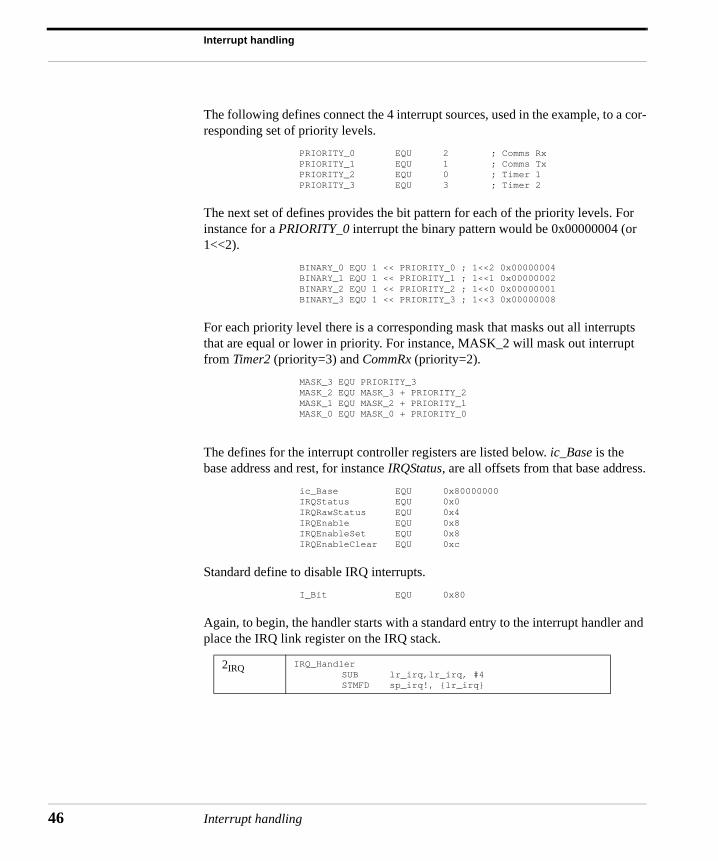
Again, to begin, the handler starts with a standard entry to the interrupt handler and place the IRQ link register on the IRQ stack.
2IRQ IRQ_HandlerSUB lr_irq,lr_irq, #4STMFD sp_irq!, {lr_irq}
Interrupt handling
Prioritized interrupt handler (1) - simple
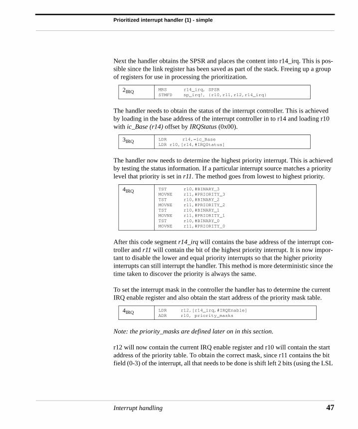
Next the handler obtains the SPSR and places the content into r14_irq. This is pos-sible since the link register has been saved as part of the stack. Freeing up a group of registers for use in processing the prioritization.
The handler needs to obtain the status of the interrupt controller. This is achieved by loading in the base address of the interrupt controller in to r14 and loading r10 with ic_Base (r14) offset by IRQStatus (0x00).
The handler now needs to determine the highest priority interrupt. This is achieved by testing the status information. If a particular interrupt source matches a priority level that priority is set in r11. The method goes from lowest to highest priority.
After this code segment r14_irq will contains the base address of the interrupt con-troller and r11 will contain the bit of the highest priority interrupt. It is now impor-tant to disable the lower and equal priority interrupts so that the higher priority interrupts can still interrupt the handler. This method is more deterministic since the time taken to discover the priority is always the same.
To set the interrupt mask in the controller the handler has to determine the current IRQ enable register and also obtain the start address of the priority mask table.
Note: the priority_masks are defined later on in this section.
r12 will now contain the current IRQ enable register and r10 will contain the start address of the priority table. To obtain the correct mask, since r11 contains the bit field (0-3) of the interrupt, all that needs to be done is shift left 2 bits (using the LSL
2IRQ MRS r14_irq, SPSRSTMFD sp_irq!, {r10,r11,r12,r14_irq}
3IRQ LDR r14,=ic_BaseLDR r10,[r14,#IRQStatus]
4IRQ TST r10,#BINARY_3MOVNE r11,#PRIORITY_3TST r10,#BINARY_2MOVNE r11,#PRIORITY_2TST r10,#BINARY_1MOVNE r11,#PRIORITY_1TST r10,#BINARY_0MOVNE r11,#PRIORITY_0
4IRQ LDR r12,[r14_irq,#IRQEnable]ADR r10, priority_masks
Interrupt handling 47
Interrupt handling
48
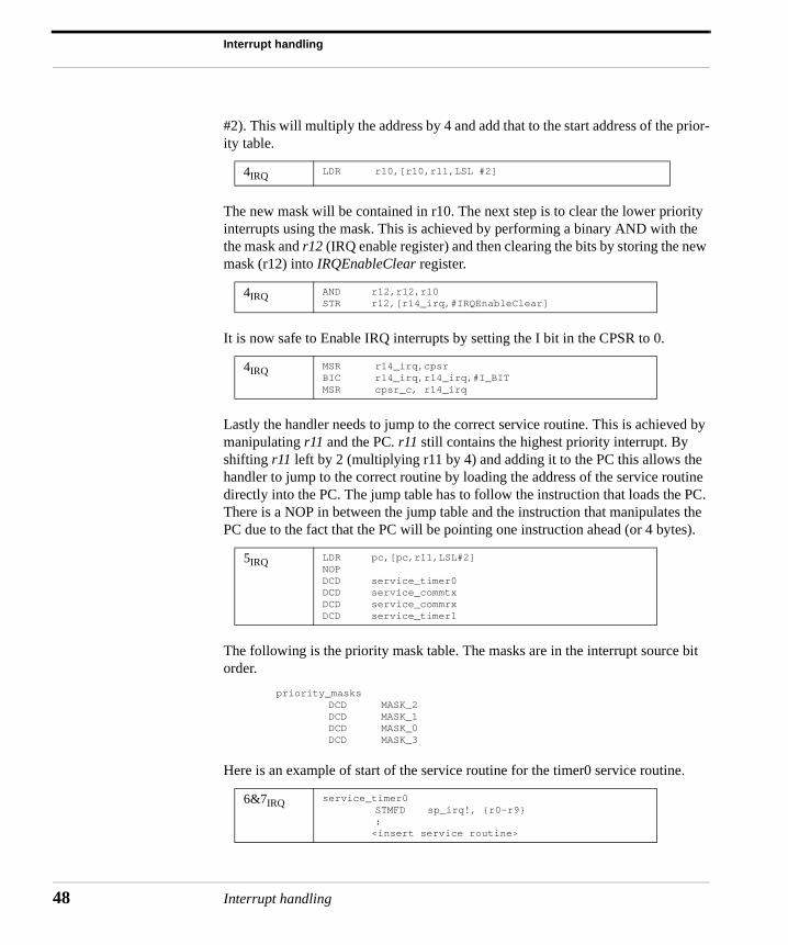
#2). This will multiply the address by 4 and add that to the start address of the prior-ity table.
The new mask will be contained in r10. The next step is to clear the lower priority interrupts using the mask. This is achieved by performing a binary AND with the the mask and r12 (IRQ enable register) and then clearing the bits by storing the new mask (r12) into IRQEnableClear register.
It is now safe to Enable IRQ interrupts by setting the I bit in the CPSR to 0.
Lastly the handler needs to jump to the correct service routine. This is achieved by manipulating r11 and the PC. r11 still contains the highest priority interrupt. By shifting r11 left by 2 (multiplying r11 by 4) and adding it to the PC this allows the handler to jump to the correct routine by loading the address of the service routine directly into the PC. The jump table has to follow the instruction that loads the PC. There is a NOP in between the jump table and the instruction that manipulates the PC due to the fact that the PC will be pointing one instruction ahead (or 4 bytes).
The following is the priority mask table. The masks are in the interrupt source bit order.
priority_masksDCD MASK_2DCD MASK_1DCD MASK_0DCD MASK_3
Here is an example of start of the service routine for the timer0 service routine.
4IRQ LDR r10,[r10,r11,LSL #2]
4IRQ AND r12,r12,r10STR r12,[r14_irq,#IRQEnableClear]
4IRQ MSR r14_irq,cpsrBIC r14_irq,r14_irq,#I_BITMSR cpsr_c, r14_irq
5IRQ LDR pc,[pc,r11,LSL#2]NOPDCD service_timer0DCD service_commtxDCD service_commrxDCD service_timer1
6&7IRQ service_timer0STMFD sp_irq!, {r0-r9}:
<insert service routine>
Interrupt handling

Prioritized interrupt handler (2) - standard
The service routine is then inserted after the header above. Once the service routine is complete the interrupt sources must be reset and control is passed back in the interrupted task.
The handler must disable the IRQ’s before the interrupt can be switched back on. This is achieved using the standard method.
The external interrupts can now be restored to their original value. This can be achieved since r12 still contains the original value. This relies on the fact that the service did not modify r12.
To return back to the interrupted task, context is restored and the original SPSR is copied back into the IRQ SPSR.
Prioritized interrupt handler (2) - standard
A simple priority interrupt handler tests all the interrupts to establish the highest priority. An alternative solution is to branch early when the highest priority inter-
7IRQ LDMFD r13_irq!, {r0-r10}
8IRQ MRS r11, cpsrORR r11, r11, #I_BIT ; disable bitMSR cpsr_c, r11
8IRQ LDR r11, =ic_BaseSTR r12, [r11,#IRQEnableSet]
9IRQ LDMFD sp!, {r11,r12,r14}MSR spsr_cf, r14_irqLDMFD sp!, {pc}^
Usage Handles higher priority interrupts in a shorter time to lower priority interrupts.
Interrupt latency Low
Advantages Higher priority interrupts treated with greater urgency with no duplication of code to set external interrupt masks etc.
Disadvantages There is a time penalty since this handler requires two jumps resulting in the pipeline being flushed each time a jump occurs.
Interrupt handling 49
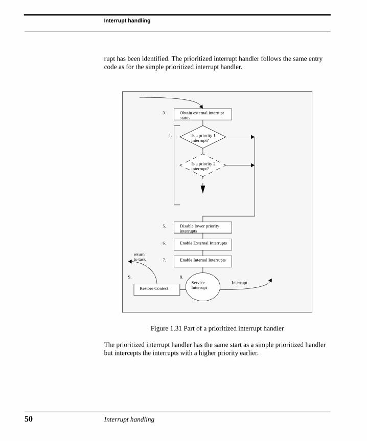
Interrupt handling
50
rupt has been identified. The prioritized interrupt handler follows the same entry code as for the simple prioritized interrupt handler.
Figure 1.31 Part of a prioritized interrupt handler
The prioritized interrupt handler has the same start as a simple prioritized handler but intercepts the interrupts with a higher priority earlier.
Obtain external interruptstatus
Is a priority 1interrupt?
Is a priority 2interrupt?
Disable lower priority interrupts
Enable External Interrupts
Enable Internal Interrupts
ServiceInterrupt
InterruptRestore Contect
returnto task
3.
4.
5.
6.
7.
8.9.
Interrupt handling
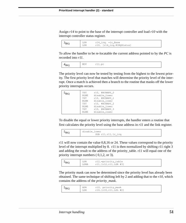
Prioritized interrupt handler (2) - standard
Assign r14 to point to the base of the interrupt controller and load r10 with the interrupt controller status register.
To allow the handler to be re-locatable the current address pointed to by the PC is recorded into r11.
The priority level can now be tested by testing from the highest to the lowest prior-ity. The first priority level that matches will determine the priority level of the inter-rupt. Once a match is achieved then a branch to the routine that masks off the lower priority interrupts occurs.
To disable the equal or lower priority interrupts, the handler enters a routine that first calculates the priority level using the base address in r11 and the link register.
r11 will now contain the value 0,8,16 or 24. These values correspond to the priority level of the interrupt multiplied by 8. r11 is then normalized by shifting r11 right 3 and adding the result to the address of the priority_table. r11 will equal one of the priority interrupt numbers ( 0,1,2, or 3).
The priority mask can now be determined since the priority level has already been obtained. The same technique of shifting left by 2 and adding that to the r10, which contains the address of the priority_mask.
3IRQ LDR r14_irq, =ic_BaseLDR r10, [r14_irq,#IRQStatus]
4IRQ MOV r11,pc
5IRQ TST r10, #BINARY_0BLNE disable_lowerTST r10, #BINARY_1BLNE disable_lowerTST r10, #BINARY_2BLNE disable_lowerTST r10, #BINARY_3BLNE disable_lower
5IRQ disable_lower SUB r11,r11,lr_irq
5IRQ LDR r12,=priority_tableLDRB r11,[r12,r11,LSR #3]
5IRQ ADR r10, priority_maskLDR r10,[r10,r11,LSL #2]
Interrupt handling 51
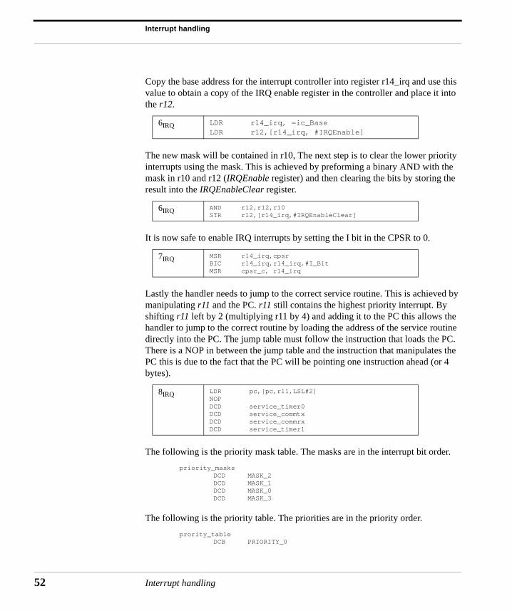
Interrupt handling
52
Copy the base address for the interrupt controller into register r14_irq and use this value to obtain a copy of the IRQ enable register in the controller and place it into the r12.
The new mask will be contained in r10, The next step is to clear the lower priority interrupts using the mask. This is achieved by preforming a binary AND with the mask in r10 and r12 (IRQEnable register) and then clearing the bits by storing the result into the IRQEnableClear register.
It is now safe to enable IRQ interrupts by setting the I bit in the CPSR to 0.
Lastly the handler needs to jump to the correct service routine. This is achieved by manipulating r11 and the PC. r11 still contains the highest priority interrupt. By shifting r11 left by 2 (multiplying r11 by 4) and adding it to the PC this allows the handler to jump to the correct routine by loading the address of the service routine directly into the PC. The jump table must follow the instruction that loads the PC. There is a NOP in between the jump table and the instruction that manipulates the PC this is due to the fact that the PC will be pointing one instruction ahead (or 4 bytes).
The following is the priority mask table. The masks are in the interrupt bit order.
priority_masksDCD MASK_2DCD MASK_1DCD MASK_0DCD MASK_3
The following is the priority table. The priorities are in the priority order.
prority_tableDCB PRIORITY_0
6IRQ LDR r14_irq, =ic_BaseLDR r12,[r14_irq, #IRQEnable]
6IRQ AND r12,r12,r10STR r12,[r14_irq,#IRQEnableClear]
7IRQ MSR r14_irq,cpsrBIC r14_irq,r14_irq,#I_BitMSR cpsr_c, r14_irq
8IRQ LDR pc,[pc,r11,LSL#2]NOPDCD service_timer0DCD service_commtxDCD service_commrxDCD service_timer1
Interrupt handling
Prioritized interrupt handler (3) - direct
DCB PRIORITY_1DCB PRIORITY_2DCB PRIORITY_3ALIGN
Prioritized interrupt handler (3) - direct
A direct prioritized interrupt handler branches directly to the interrupt service rou-tine (ISR). Each ISR is responsible for disabling the lower priority interrupts before modifying the CPSR so that interrupts are re-enabled. This type of handler is rela-tively simple since the masking is done by the service routine. This does cause min-imal duplication of code since each service routine is effectively carrying out the same task.
Below is a set of defines that associates an interrupt source with a bit position within the interrupt controller. This will be used to help mask the lower priority within the ISR’s.
bit_timer0 EQU 0bit_commtx EQU 1bit_commrx EQU 2bit_timer1 EQU 3
To begin, the base address of the ISR table has to be loaded into r12. This register is used to jump to the correct ISR once the priority has been established for the inter-rupt source.
ADR r12, isr_table
Then identify the priority and interrupt. This is achieved by checking the highest priority interrupt first and then working down to the lowest. Once a high priority interrupt is identified the PC is then loaded with the address of the appropriate ISR.
Usage Handles higher priority interrupts in a shorter time goes directly to the specific service routine.
Interrupt latency Low
Advantages Uses on a single jump and saves valuable cycles to go to the service.
Disadvantages Each service routine has to have a mechanism to set the external interrupt mask to stop lower priority interrupts from halting the service routine.
Interrupt handling 53
Interrupt handling
54
The indirect address is stored at the address of the isr_table plus the priority level shifted 2 bits to the left (a multiple of 4).
TST r10,#BINARY_0LDRNE pc,[r12,#PRIORITY_0,LSL #2]TST r10,#BINARY_1LDRNE pc,[r12,#PRIORITY_1,LSL #2]TST r10,#BINARY_2LDRNE pc,[r12,#PRIORITY_2,LSL #2]TST r10,#BINARY_3LDRNE pc,[r12,#PRIORITY_3,LSL #2]
Note: r10 contains the IRQStatus register.
The following is the ISR jump table. The ISR jump table ordered with the highest priority interrupt at the beginning of the table.
isr_tableDCD service_timer0DCD service_commtxDCD service_commrxDCD service_timer1
The service_timer0 shows an example of ISR used in a direct priority interrupt handler. Each ISR has to change depending upon the particular interrupt source. The source bit of the interrupt is first moved into r11.
service_timer0MOV r11,#bit_timer0
A copy the base address for the interrupt controller placed into register r14_irq and this address plus offset is used to obtain a copy of the IRQEnable register on con-troller and subsequently this is placed into r12.
LDR r14_irq, =ic_BaseLDR r12,[r14_irq,#IRQEnable]
The address of the priority mask table has to be copied into r10 so it can be used to calculate the address of the actual mask. R11 is shifted left 2 positions. This give an offset 0,4,8, or 12. This plus the address of the priority mask table address to used to load the mask into r10. The priority mask table is the same for the priority inter-rupt handler in the previous section.
ADR r10,priority_masksLDR r10,[r10,r11,LSL#2]
r10 will contain the ISR mask and r12 will contain the current mask. The binary operation of an AND is used to merge the two masks. Then the new mask is used to set the interrupt controller using IRQEnableClear register.
AND r12,r12,r10
Interrupt handling
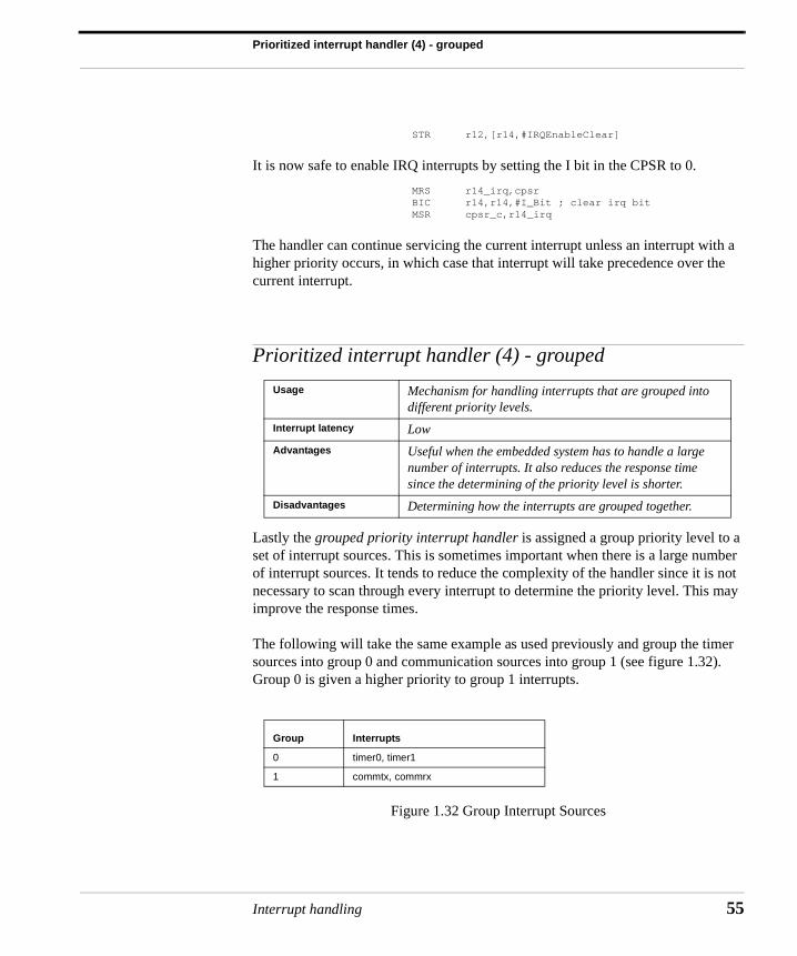
Prioritized interrupt handler (4) - grouped
STR r12,[r14,#IRQEnableClear]
It is now safe to enable IRQ interrupts by setting the I bit in the CPSR to 0.
MRS r14_irq,cpsrBIC r14,r14,#I_Bit ; clear irq bitMSR cpsr_c,r14_irq
The handler can continue servicing the current interrupt unless an interrupt with a higher priority occurs, in which case that interrupt will take precedence over the current interrupt.
Prioritized interrupt handler (4) - grouped
Lastly the grouped priority interrupt handler is assigned a group priority level to a set of interrupt sources. This is sometimes important when there is a large number of interrupt sources. It tends to reduce the complexity of the handler since it is not necessary to scan through every interrupt to determine the priority level. This may improve the response times.
The following will take the same example as used previously and group the timer sources into group 0 and communication sources into group 1 (see figure 1.32). Group 0 is given a higher priority to group 1 interrupts.
Figure 1.32 Group Interrupt Sources
Usage Mechanism for handling interrupts that are grouped into different priority levels.
Interrupt latency Low
Advantages Useful when the embedded system has to handle a large number of interrupts. It also reduces the response time since the determining of the priority level is shorter.
Disadvantages Determining how the interrupts are grouped together.
Group Interrupts
0 timer0, timer1
1 commtx, commrx
Interrupt handling 55
Interrupt handling
56
The following defines group the various interrupt sources into their priority group. This is achieved by using a binary OR operation on the binary patterns.
GROUP_0 EQU BINARY_0+BINARY_3 GROUP_1 EQU BINARY_1+BINARY_2
The following defines group the various masks for the interrupts together.
GMASK_1 EQU GROUP_1GMASK_0 EQU AMASK_1+GROUP_0
These defines provide the connection of masks to interrupt sources. This can then used in the priority mask table.
MASK_TIMER0 EQU GMASK_0MASK_COMMTX EQU GMASK_1MASK_COMMRX EQU GMASK_1MASK_TIMER1 EQU GMASK_0
The below show shows the start of a standard interrupt handler.
interrupt_handlerSUB lr,lr,#4
STMFD sp_irq,{lr}MRS r14,spsr_irqSTMFD sp_irq!,{r10,r11,r12,r14}
Obtain the status of the interrupt using the standard mechanism of using an offset from the interrupt controller.
LDR r14_irq, =ic_BaseLDR r10, [r14_irq,#IRQStatus]
Identify the group that the interrupt sources belong. This is achieved by using the binary AND operation on the source. The letter ‘S’ post-fixed to the instructions means update execution flag on the CPSR.
ANDS r11,r10,#GROUP_0ANDEQS r11,r10,#GROUP_1
r11 will now contain the highest priority group (0 or 1). Now mask out the other interrupt sources by applying a binary AND operation with 0xf.
AND r10,r11,#0xf
Load the address of the lowest significant bit table and then load the byte offset from the start of the table by the value in r10 (0,1,2, or 3 see figure 1.33). Once the
Interrupt handling
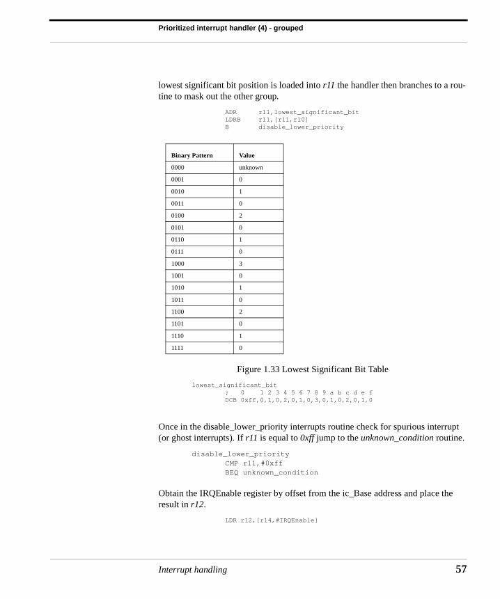
Prioritized interrupt handler (4) - grouped
lowest significant bit position is loaded into r11 the handler then branches to a rou-tine to mask out the other group.
ADR r11,lowest_significant_bitLDRB r11,[r11,r10]B disable_lower_priority
Figure 1.33 Lowest Significant Bit Table
lowest_significant_bit; 0 1 2 3 4 5 6 7 8 9 a b c d e fDCB 0xff,0,1,0,2,0,1,0,3,0,1,0,2,0,1,0
Once in the disable_lower_priority interrupts routine check for spurious interrupt (or ghost interrupts). If r11 is equal to 0xff jump to the unknown_condition routine.
disable_lower_priorityCMP r11,#0xffBEQ unknown_condition
Obtain the IRQEnable register by offset from the ic_Base address and place the result in r12.
LDR r12,[r14,#IRQEnable]
Binary Pattern Value
0000 unknown
0001 0
0010 1
0011 0
0100 2
0101 0
0110 1
0111 0
1000 3
1001 0
1010 1
1011 0
1100 2
1101 0
1110 1
1111 0
Interrupt handling 57
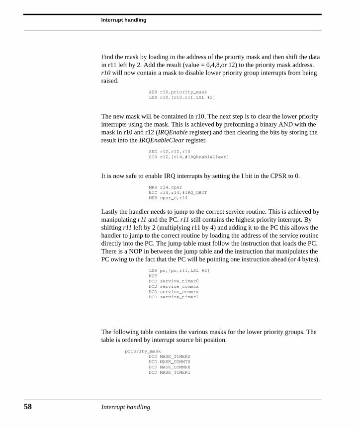
Interrupt handling
58
Find the mask by loading in the address of the priority mask and then shift the data in r11 left by 2. Add the result (value = 0,4,8,or 12) to the priority mask address. r10 will now contain a mask to disable lower priority group interrupts from being raised.
ADR r10,priority_maskLDR r10,[r10,r11,LSL #2]
The new mask will be contained in r10, The next step is to clear the lower priority interrupts using the mask. This is achieved by preforming a binary AND with the mask in r10 and r12 (IRQEnable register) and then clearing the bits by storing the result into the IRQEnableClear register.
AND r12,r12,r10STR r12,[r14,#IRQEnableClear]
It is now safe to enable IRQ interrupts by setting the I bit in the CPSR to 0.
MRS r14,cpsrBIC r14,r14,#IRQ_QBITMSR cpsr_c,r14
Lastly the handler needs to jump to the correct service routine. This is achieved by manipulating r11 and the PC. r11 still contains the highest priority interrupt. By shifting r11 left by 2 (multiplying r11 by 4) and adding it to the PC this allows the handler to jump to the correct routine by loading the address of the service routine directly into the PC. The jump table must follow the instruction that loads the PC. There is a NOP in between the jump table and the instruction that manipulates the PC owing to the fact that the PC will be pointing one instruction ahead (or 4 bytes).
LDR pc,[pc,r11,LSL #2]NOPDCD servive_timer0DCD service_commtxDCD service_commrxDCD service_timer1
The following table contains the various masks for the lower priority groups. The table is ordered by interrupt source bit position.
priority_maskDCD MASK_TIMER0DCD MASK_COMMTXDCD MASK_COMMRXDCD MASK_TIMER1
Interrupt handling
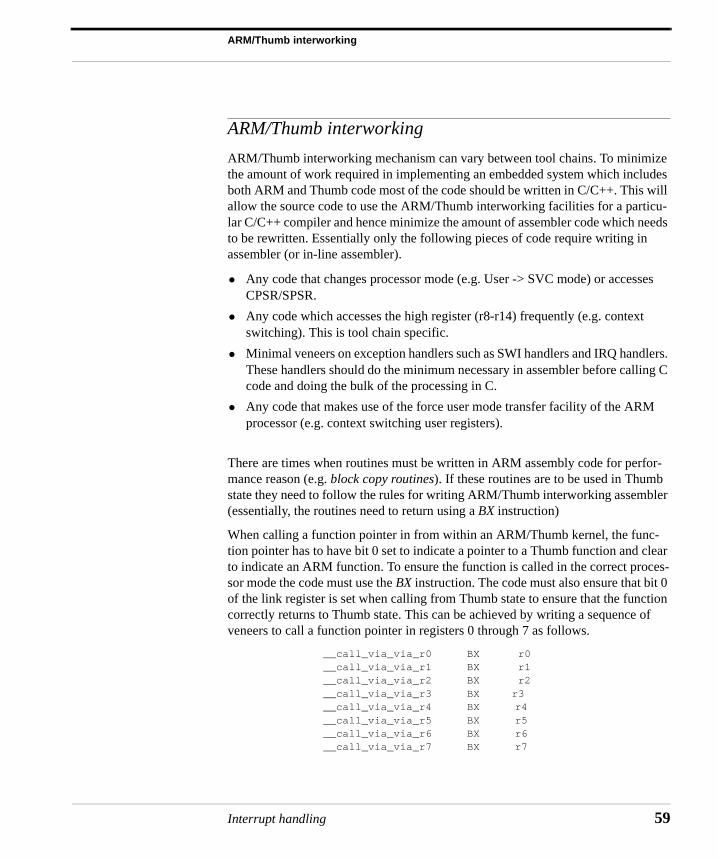
ARM/Thumb interworking
ARM/Thumb interworking
ARM/Thumb interworking mechanism can vary between tool chains. To minimize the amount of work required in implementing an embedded system which includes both ARM and Thumb code most of the code should be written in C/C++. This will allow the source code to use the ARM/Thumb interworking facilities for a particu-lar C/C++ compiler and hence minimize the amount of assembler code which needs to be rewritten. Essentially only the following pieces of code require writing in assembler (or in-line assembler).
• Any code that changes processor mode (e.g. User -> SVC mode) or accesses CPSR/SPSR.
• Any code which accesses the high register (r8-r14) frequently (e.g. context switching). This is tool chain specific.
• Minimal veneers on exception handlers such as SWI handlers and IRQ handlers. These handlers should do the minimum necessary in assembler before calling C code and doing the bulk of the processing in C.
• Any code that makes use of the force user mode transfer facility of the ARM processor (e.g. context switching user registers).
There are times when routines must be written in ARM assembly code for perfor-mance reason (e.g. block copy routines). If these routines are to be used in Thumb state they need to follow the rules for writing ARM/Thumb interworking assembler (essentially, the routines need to return using a BX instruction)
When calling a function pointer in from within an ARM/Thumb kernel, the func-tion pointer has to have bit 0 set to indicate a pointer to a Thumb function and clear to indicate an ARM function. To ensure the function is called in the correct proces-sor mode the code must use the BX instruction. The code must also ensure that bit 0 of the link register is set when calling from Thumb state to ensure that the function correctly returns to Thumb state. This can be achieved by writing a sequence of veneers to call a function pointer in registers 0 through 7 as follows.
__call_via_via_r0 BX r0__call_via_via_r1 BX r1__call_via_via_r2 BX r2__call_via_via_r3 BX r3__call_via_via_r4 BX r4__call_via_via_r5 BX r5__call_via_via_r6 BX r6__call_via_via_r7 BX r7
Interrupt handling 59
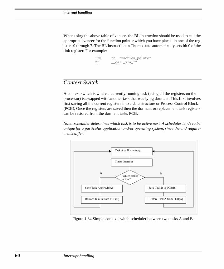
Interrupt handling
60
When using the above table of veneers the BL instruction should be used to call the appropriate veneer for the function pointer which you have placed in one of the reg-isters 0 through 7. The BL instruction in Thumb state automatically sets bit 0 of the link register. For example:
LDR r2, function_pointer BL __call_via_r2
Context Switch
A context switch is where a currently running task (using all the registers on the processor) is swapped with another task that was lying dormant. This first involves first saving all the current registers into a data structure or Process Control Block (PCB). Once the registers are saved then the dormant or replacement task registers can be restored from the dormant tasks PCB.
Note: scheduler determines which task is to be active next. A scheduler tends to be unique for a particular application and/or operating system, since the end require-ments differ.
Figure 1.34 Simple context switch scheduler between two tasks A and B
Task A or B - running
Timer Interrupt
Which task is
Save Task A to PCB(A) Save Task B to PCB(B)
Restore Task B from PCB(B) Restore Task A from PCB(A)
active?
A B
Interrupt handling
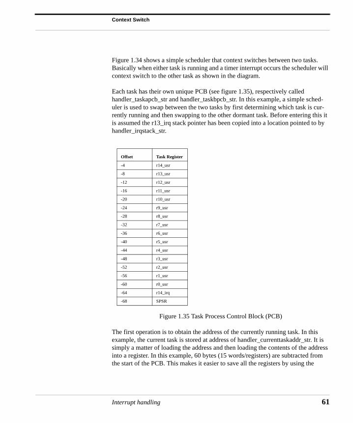
Context Switch
Figure 1.34 shows a simple scheduler that context switches between two tasks. Basically when either task is running and a timer interrupt occurs the scheduler will context switch to the other task as shown in the diagram.
Each task has their own unique PCB (see figure 1.35), respectively called handler_taskapcb_str and handler_taskbpcb_str. In this example, a simple sched-uler is used to swap between the two tasks by first determining which task is cur-rently running and then swapping to the other dormant task. Before entering this it is assumed the r13_irq stack pointer has been copied into a location pointed to by handler_irqstack_str.
Figure 1.35 Task Process Control Block (PCB)
The first operation is to obtain the address of the currently running task. In this example, the current task is stored at address of handler_currenttaskaddr_str. It is simply a matter of loading the address and then loading the contents of the address into a register. In this example, 60 bytes (15 words/registers) are subtracted from the start of the PCB. This makes it easier to save all the registers by using the
Offset Task Register
-4 r14_usr
-8 r13_usr
-12 r12_usr
-16 r11_usr
-20 r10_usr
-24 r9_usr
-28 r8_usr
-32 r7_usr
-36 r6_usr
-40 r5_usr
-44 r4_usr
-48 r3_usr
-52 r2_usr
-56 r1_usr
-60 r0_usr
-64 r14_irq
-68 SPSR
Interrupt handling 61
Interrupt handling
62
ascending and descending multiple register load and store instructions (STM/LDM).
LDR r13_irq, =handler_currenttaskaddr_strLDR r13_irq, [r13_irq]SUB r13_irq, r13_irq,#60
r13_irq is then pointing to r0_usr. The current user task registers are then stored into the PCB by using ‘^’ post-fixed at the end of the STMIA (ascends memory) instruction. Then a copy is made of the SPSR into r0 since r0 can be used as a scratch register since it has already been stored into the PCB. The ‘!’ has not been used so r13_irq is still pointing to -60 offset, this means it can be used to store the rest of the PCB. This is achieved using STMDB (descends memory) by saving r0 (SPSR) and r14_irq (return address of the interrupted task) into the PCB.
STMIA r13_irq, {r0-r14}^MRS r0, SPSRSTMDB r13_irq, {r0,r14_irq}
The current task has had all the registers stored into the PCB. The new task regis-ters now have to be loaded into the register set. This is achieved by first copying the address of the location the next task PCB is held. This address is called handler_nexttask_str. Again, -60 bytes are removed from the start of the PCB. This is so the best possible use of the load and store multiple register instruction are achieved with descending and ascending options.
LDR r13_irq, =handler_nexttask_strLDR r13_irq, [r13_irq]SUB r13_irq, r13_irq,#60<task swap code>
At this point there has to be code to update the current and next tasks so that when the next context switch occurs the handler_currenttask_str holds the handler_nexttask_str data and vice-versa. The next step is to obtain the SPSR and IRQ link register and place it into r0 and r14_irq respectively. Then copy r0 into the IRQ SPSR.
LDMDB r13_irq, {r0,r14_irq}MSR spsr_cxsf, r0
The user banked registers can now be restored. This is achieved by using the ‘^’ again to restore the user register for the next task. Note a NOP should always fol-low LDMIA instruction with ‘^’ incase a register is corrupted.
LDMIA r13_irq, {r0-r14}^NOP
Interrupt handling
Context Switch
It is now important to return the original IRQ stack. This is achieved by loading the address of the IRQ stack into r13_irq. Then load r13_irq with the 32-bit word con-taining the IRQ stack back into r13_irq.
LDR r13_irq, =handler_irqstack_strLDR r13_irq,[r13_irq]
Lastly the context can relinquish control of the processor and return back to the interrupted task. This is achieved by subtracting from the IRQ link register.
SUBS pc, r14_irq, #4
The following holds the address of the currently run task. It is assumed that the ini-tialization code sets this address correctly.
handler_currenttaskaddr_strDCD 0x0
The following holds the address of the next PCB to be run.
handler_nexttask_strDCD 0x0
Store a copy of the IRQ stack thus freeing up the r13_irq for other uses.
handler_irqstack_strDCD 0x0
This context PCB for task A. The ‘% 68’ indicated 68 bytes.
handler_taskabottom% 68
handler_taskapcb_str
Likewise for task B PCB.
handler_taskbbottom% 68
handler_taskbpcb_str
Note: a context switch should not occur within a handler that is nested (been recur-sively invoked). This is because the registers being switched will be the previous handler that was invoked instead of the application registers. A counter variable can be used to indicate the depth of a nested handler. If zero then a context switch can be allowed to occur.
Interrupt handling 63
Interrupt handling
64
Semaphore
A semaphore is a way of locking a process from interfering with data. Sharing data is useful for message passing and multi-processing environments. The mechanism is called inter-processor communication.
unsigned int semaphore;
...
The semaphore must make use of the SWP instruction. The SWP instruction is an atomic instruction which holds the CPU bus until the SWP transaction is complete. The swaps the contents of a register and memory in a single instruction.
void mutex_gatelock (void){
__asm { spin: MOV r1, &semaphore MOV r2, #1 SWP r3,r2,[r1] CMP r3,#1 BEQ spin } }
void mutex_gateunlock (void)
{__asm {MOV r1, &semaphoreMOV r2, #0SWP r0,r2,[r1]}
}
Debug
Interrupt handlers can be difficult to debug and thus more time should be spent on the planning and understanding of the interrupt mechanism. A careful design can avoid race conditions or deadlock occurring. A simple way to help debug systems is to slow the system down and use a simple LED to indicate when the interrupt handler code is being executed or not. Obviously, if there is EmbeddedICE/Trace/Logic Analyzer technology then these devices can be used to help debugging the code. If there is a spare serial port or communication channel then it can be used to
Interrupt handling
General Notes for Real Time Operating System
record history of activities. This will require post analyzing of the history log to determine the source of the problem.
General Notes for Real Time Operating System
Below are a set of general notes for designing an interrupt handler.
• The example code in this chapter assumes a perfect system unfortunately this is seldom the case. There are times when ghost or rogue interrupts occur. It is up to the designer of the interrupt handler to anticipate these spurious interrupts and handle them appropriately.
• Reducing the number of registers being transferred by LDM and STM will reduce the interrupt latency since the ARM processor will complete the execu-tion of the current instruction in the pipeline.
• If it is a requirement that the RTOS be called from User mode in addition to System or Supervisor (SVC) mode then you will need to use the SWI interface to call the various RTOS API’s.
• The RTOS must run in System or SVC mode in order to perform operations which are prohibited in user mode such as enabling or disabling interrupts. The SWI mechanism provides a means whereby a user level task can call the RTOS in SVC mode.
• If the embedded system is to be callable only from System or SVC mode there is no requirement to use the SWI interface. This can significantly simplify the design of the ABI.
• If the RTOS is directly linked with the application RTOS, calls can be made using a simple BL instruction (i.e. a direct C function call).
• If the RTOS must be separately linked then the application must call the RTOS indirectly. Typically this is done via a table of function pointers which is initial-ized by the RTOS on startup.
• Many RTOS’s require a single entry/exit point. There are a number of reasons for this requirement. The RTOS may need to perform rescheduling on exit from an RTOS call. Without a single entry/exit call mechanism each RTOS function must arrange to call the scheduler on exit.
• A debug monitor may need to monitor calls to the RTOS to allow breakpoints to be set on system calls or to allow profiling of RTOS calls.
Interrupt handling 65
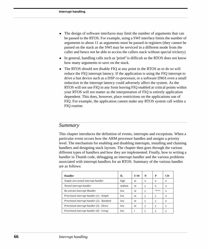
Interrupt handling
66
• The design of software interfaces may limit the number of arguments that can be passed to the RTOS. For example, using a SWI interface limits the number of arguments to about 11 as arguments must be passed in registers (they cannot be passed on the stack as the SWI may be serviced in a different mode from the caller and hence not be able to access the callers stack without special trickery).
• In general, handling calls such as ’printf’ is difficult as the RTOS does not know how many arguments to save on the stack.
• The RTOS should not disable FIQ at any point in the RTOS as to do so will reduce the FIQ interrupt latency. If the application is using the FIQ interrupt to drive a fast device such as a DSP co-processor, or a software DMA even a small reduction in the interrupt latency could adversely affect the system. As the RTOS will not use FIQ in any form leaving FIQ enabled at critical points within your RTOS will not matter as the interpretation of FIQ is entirely application dependent. This does, however, place restrictions on the applications use of FIQ. For example, the application cannot make any RTOS system call within a FIQ routine.
Summary
This chapter introduces the definition of events, interrupts and exceptions. When a particular event occurs how the ARM processor handles and assigns a priority level. The mechanism for enabling and disabling interrupts, installing and chaining handlers and designing stack layouts. The chapter then goes through the various different types of handlers and how they are implemented. Finally, how to writing a handler in Thumb code, debugging an interrupt handler and the various problems associated with interrupt handlers for an RTOS. Summary of the various handler are as follows:
Handler IL I>10 N P CD
Simple non-nested interrupt handler high nr n n n
Nested interrupt handler nedium nr y n n
Re-entrant Interrupt Handler low nr y Optional n
Prioritized interrupt handler (1) - Simple low nr y y n
Prioritized interrupt handler (2) - Standard low nr y y n
Prioritized interrupt handler (3) - Direct low nr y y y
Prioritized interrupt handler (4) - Group low r y y y
Interrupt handling
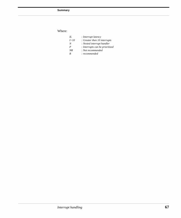
Summary
Where:
IL : Interrupt latencyI>10 : Greater then 10 interruptsN : Nested interrupt handlerP : Interrupts can be prioritizedNR : Not recommendedR : recommended
Interrupt handling 67

Interrupt handling
68
Interrupt handling