Interpreting Technical Drawing
19
Technical Drafting NC II Date Developed: Date Revised: Document No. Issued by: Page 1 of 18 Developed by: Jouie C. Tabilin Revision # 01 COMPETENCY-BAS ED LEARNING MATERIAL Sector: METALS AND ENGINEERING Qualification: Techni cal Drafti ng NC I I Unit of Competency: Interpreting Technical Drawings And Plans TECHNICAL EDUCATION AND SKILLS DEVELOPMENT AUTHORITY East Service Road, South Superhighway, Taguig City, Metro Manila
-
Upload
wyzty-delle -
Category
Documents
-
view
231 -
download
0
Transcript of Interpreting Technical Drawing

7/26/2019 Interpreting Technical Drawing
http://slidepdf.com/reader/full/interpreting-technical-drawing 1/18
TechnicalDrafting NC II
Date Developed:
Date Revised:
Document No.
Issued by:
Page 1 of 18
Developed by:
Jouie C. Tabilin Revision # 01
COMPETENCY-BASED LEARNING MATERIAL
Sector:
METALS AND ENGINEERING
Qualification:
Technical Drafting NC IIUnit of Competency:
Interpreting Technical Drawings And Plans
TECHNICAL EDUCATION AND SKILLS DEVELOPMENT
AUTHORITY
East Service Road, South Superhighway, Taguig City, Metro Manila
7/26/2019 Interpreting Technical Drawing
http://slidepdf.com/reader/full/interpreting-technical-drawing 2/18
TechnicalDrafting NC II
Date Developed:
Date Revised:
Document No.
Issued by:
Page 2 of 18
Developed by:
Jouie C. Tabilin Revision # 01
TABLE OF CONTENTS
Content Page Number
I LEARNING GUIDE OVERVIEW ........................................................................................ 3
II HOW
TO
USE
THIS
GUIDE
..............................................................................................
4
III LEARNING ACTIVITIES .................................................................................................... 5
IV INFORMATION SHEET 1: ALPHABET OF LINES ............................................................... 6
INFORMATION SHEET 2: ORTHOGRAPHIC PROJECTION
A) ORTHOGRAPHIC PROJECTION .......................................................................... 9
B) STEPS IN SELECTING CORRECT VIEWS OF AN OBJECT ...................................... 9
C) PRINCIPAL DIMENSIONS OF AN OBJECT ............................................................ 10
D) STEPS IN PROJECTING THE THREE MAIN VIEWS OF AN OBJECT ....................... 11
V SELF CHECK 1 .................................................................................................................. 8
SELF‐CHECK 2 ................................................................................................................. 13
VI ACTIVITY SHEET NO. 1: SKETCHING THREE MAIN VIEWS OF AN OBJECT ....................... 14
VII ANSWER KEYS ................................................................................................................ 16‐17
VIII RECORD OF COMPETENCE .......................................................................................... 18
7/26/2019 Interpreting Technical Drawing
http://slidepdf.com/reader/full/interpreting-technical-drawing 3/18
TechnicalDrafting NC II
Date Developed:
Date Revised:
Document No.
Issued by:
Page 3 of 18
Developed by:
Jouie C. Tabilin Revision # 01
LEARNING GUIDE OVERVIEW
In the broad field of technical drawings, various projection methods are used to
represent objects. Each method has its own advantages and disadvantages.
The normal technical drawing is shown in orthogonal projection, in which more than
one view is used to draw and completely define an object.
However, to be able to represent the different views of an object one must be
acquainted with the different forms of lines. The various lines used in drawing form the
alphabet of the drafting language.
In this learning material, the students should be able to apply the alphabet of lines in
projecting the principal views of an object.
Competencies will be demonstrated by completing the job sheet and the unit test with
a minimum score of 75 percent.OBJECTIVES When you have successfully completed the learning activities in
this material, you will be able to:
1. Identify the different alphabet of lines;
2. Steps in selecting correct views of an object;
3. Identify the dimensions of an object; and
4. Project the three main views of an object.
CONTENTS This learning material includes the following:
1. Alphabet of lines
2. Orthographic Projection
3. Steps in Selecting Correct Views of an Object
4. Principal Dimensions of an Object
5. Steps in Projecting the Three Main Views
PRE-REQUISITES The completion of this learning material requires you to have a
basic understanding of:
If you are unfamiliar with any of the above concepts, work
on________ before working on this learning guide.
7/26/2019 Interpreting Technical Drawing
http://slidepdf.com/reader/full/interpreting-technical-drawing 4/18
TechnicalDrafting NC II
Date Developed:
Date Revised:
Document No.
Issued by:
Page 4 of 18
Developed by:
Jouie C. Tabilin Revision # 01
HOW TO USE THIS LEARNING GUIDE
This Learning Guide will lead you through a series of activities which will require you to work
at your own pace. These activities will ask you to complete associated learning and practice
activities in order to gain the knowledge and skills you need to achieve the learning
objectives stated earlier.
Refer to Learning Activity Page to know the sequence of learning tasks to undergo and the
appropriate resources to use in each task. This page will serve as your road map towards
the achievement of objectives.
Read the information sheets. This will give you an understanding of the work, and why
things are done the way they are.
Complete the activities as directed in the activity/practice sheets. These will test your
knowledge and give you practice of doing the tasks involved. Performance criteria for
assessing practical exercise are shown to guide you in undertaking the practical exercises. Always be aware of safety requirements highlighted in this material. Ask for clearance in
using some tools and equipment. Should you require some assistance and clarification,
consult your trainer or facilitator. They should be available anytime you need them.
Answer self-checks found in each section of the learning guide. Do not write anything on
this learning guide; provide separate sheets for your answers. Self-checks will let you know
how you are going. To know how you fared with self checks, review the answer keys found
at the end of the learning guide.
When you had completed all the tasks required in this learning guide, an assessment
exercise will be given to evaluate if you are already competent with the specified learningoutcomes in and ready for the next task. .If you feel ready for the assessment, consult the
facilitator.
A record of competency is provided on the last page to reflect how much of the required
assessment criteria have been met.
You may already have some or most of the knowledge and skills covered in this learner’s
guide.
Talk to your trainer about having them formally recognized. If you have qualification or
certificate of competence from previous training, show it to your trainer. If the skills youacquired are still current and relevant to the unit of competency they may become part of the
evidence you can present for Recognition of Prior Learning (RPL). If you are not sure
about the accuracy of your skills, discuss it with your trainer.
7/26/2019 Interpreting Technical Drawing
http://slidepdf.com/reader/full/interpreting-technical-drawing 5/18
TechnicalDrafting NC II
Date Developed:
Date Revised:
Document No.
Issued by:
Page 5 of 18
Developed by:
Jouie C. Tabilin Revision # 01
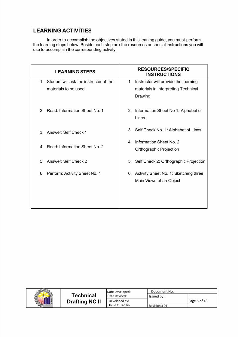
LEARNING ACTIVITIES
In order to accomplish the objectives stated in this leaning guide, you must performthe learning steps below. Beside each step are the resources or special instructions you willuse to accomplish the corresponding activity.
LEARNING STEPSRESOURCES/SPECIFIC
INSTRUCTIONS
1. Student will ask the instructor of the
materials to be used
2. Read: Information Sheet No. 1
3. Answer: Self Check 1
4. Read: Information Sheet No. 2
5. Answer: Self Check 2
6. Perform: Activity Sheet No. 1
1. Instructor will provide the learning
materials in Interpreting Technical
Drawing
2. Information Sheet No 1: Alphabet of
Lines
3. Self Check No. 1: Alphabet of Lines
4. Information Sheet No. 2:
Orthographic Projection
5. Self Check 2: Orthographic Projection
6. Activity Sheet No. 1: Sketching three
Main Views of an Object
7/26/2019 Interpreting Technical Drawing
http://slidepdf.com/reader/full/interpreting-technical-drawing 6/18
TechnicalDrafting NC II
Date Developed:
Date Revised:
Document No.
Issued by:
Page 6 of 18
Developed by:
Jouie C. Tabilin Revision # 01
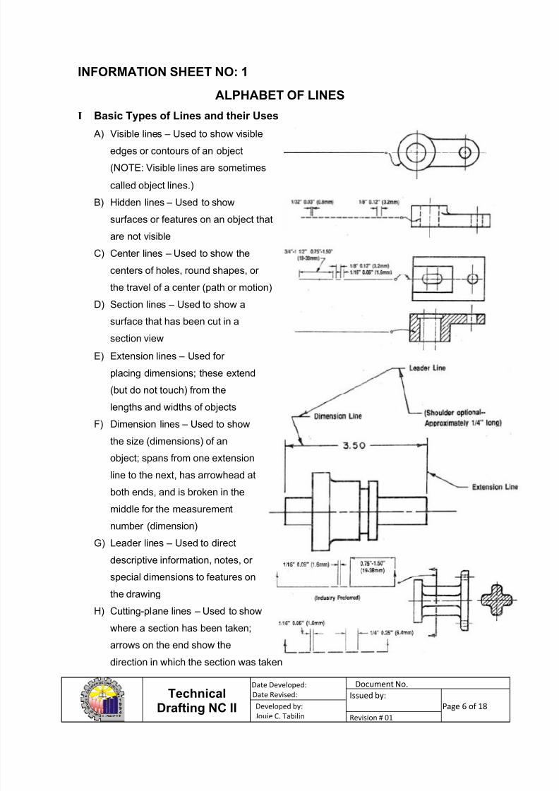
INFORMATION SHEET NO: 1
ALPHABET OF LINES
I Basic Types of Lines and their Uses
A) Visible lines – Used to show visible
edges or contours of an object
(NOTE: Visible lines are sometimes
called object lines.)
B) Hidden lines – Used to show
surfaces or features on an object that
are not visible
C) Center lines – Used to show the
centers of holes, round shapes, or
the travel of a center (path or motion)
D) Section lines – Used to show a
surface that has been cut in a
section view
E) Extension lines – Used for
placing dimensions; these extend
(but do not touch) from the
lengths and widths of objects
F) Dimension lines – Used to show
the size (dimensions) of an
object; spans from one extension
line to the next, has arrowhead at
both ends, and is broken in the
middle for the measurement
number (dimension)
G) Leader lines – Used to direct
descriptive information, notes, or
special dimensions to features on
the drawing
H) Cutting-plane lines – Used to show
where a section has been taken;
arrows on the end show the
direction in which the section was taken
7/26/2019 Interpreting Technical Drawing
http://slidepdf.com/reader/full/interpreting-technical-drawing 7/18
TechnicalDrafting NC II
Date Developed:
Date Revised:
Document No.
Issued by:
Page 7 of 18
Developed by:
Jouie C. Tabilin Revision # 01
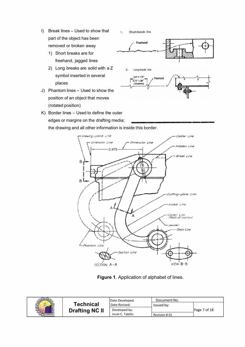
I) Break lines – Used to show that
part of the object has been
removed or broken away
1) Short breaks are for
freehand, jagged lines
2) Long breaks are solid with a Z
symbol inserted in several
places
J) Phantom lines – Used to show the
position of an object that moves
(rotated position)
K) Border lines – Used to define the outer
edges or margins on the drafting media;
the drawing and all other information is inside this border.
Figure 1. Application of alphabet of lines.
7/26/2019 Interpreting Technical Drawing
http://slidepdf.com/reader/full/interpreting-technical-drawing 8/18
TechnicalDrafting NC II
Date Developed:
Date Revised:
Document No.
Issued by:
Page 8 of 18
Developed by:
Jouie C. Tabilin Revision # 01
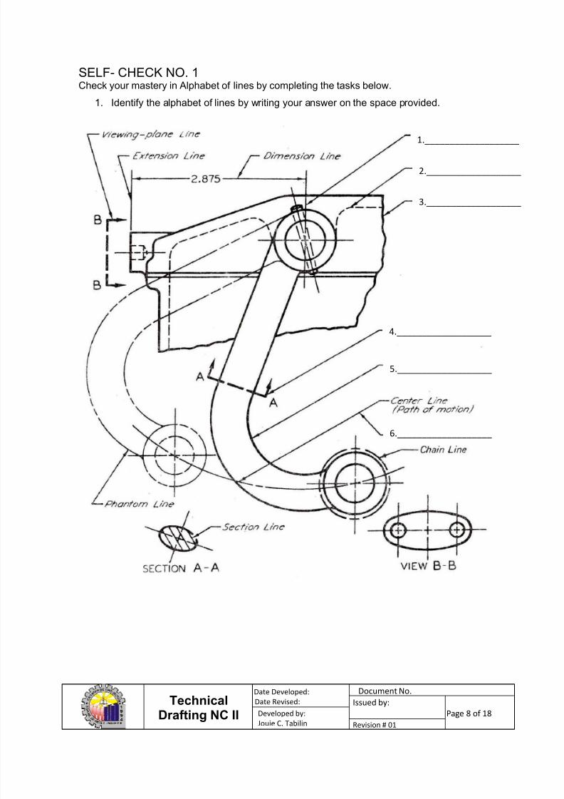
SELF- CHECK NO. 1Check your mastery in Alphabet of lines by completing the tasks below.
1. Identify the alphabet of lines by writing your answer on the space provided.
1.___________________
2.___________________
3.___________________
4.___________________
5.___________________
6.___________________
7/26/2019 Interpreting Technical Drawing
http://slidepdf.com/reader/full/interpreting-technical-drawing 9/18
TechnicalDrafting NC II
Date Developed:
Date Revised:
Document No.
Issued by:
Page 9 of 18
Developed by:
Jouie C. Tabilin Revision # 01
INFORMATION SHEET NO: 2
ORTHOGRAPHIC PROJECTION
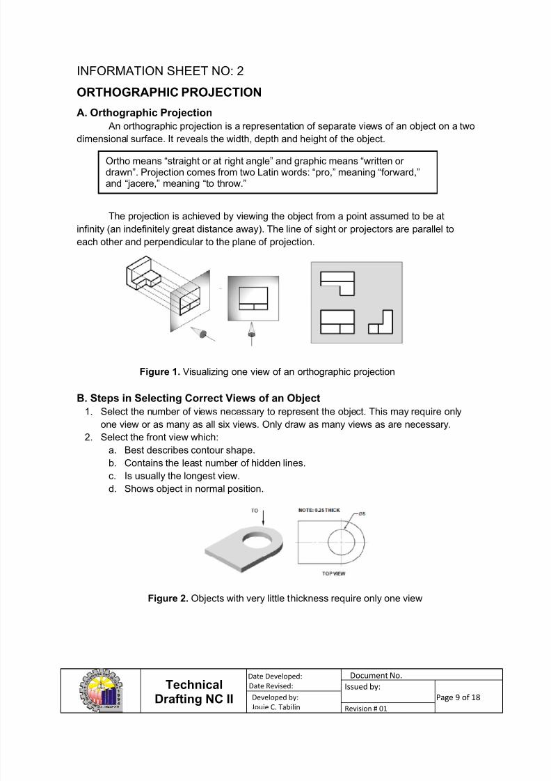
A. Orthographic Projection
An orthographic projection is a representation of separate views of an object on a twodimensional surface. It reveals the width, depth and height of the object.
The projection is achieved by viewing the object from a point assumed to be at
infinity (an indefinitely great distance away). The line of sight or projectors are parallel to
each other and perpendicular to the plane of projection.
B. Steps in Selecting Correct Views of an Object
1. Select the number of views necessary to represent the object. This may require only
one view or as many as all six views. Only draw as many views as are necessary.
2. Select the front view which:
a. Best describes contour shape.
b. Contains the least number of hidden lines.
c. Is usually the longest view.
d. Shows object in normal position.
Ortho means “straight or at right angle” and graphic means “written ordrawn”. Projection comes from two Latin words: “pro,” meaning “forward,”and “jacere,” meaning “to throw.”
Figure 1. Visualizing one view of an orthographic projection
Figure 2. Objects with very little thickness require only one view
7/26/2019 Interpreting Technical Drawing
http://slidepdf.com/reader/full/interpreting-technical-drawing 10/18
TechnicalDrafting NC II
Date Developed:
Date Revised:
Document No.
Issued by:
Page 10 of 18
Developed by:
Jouie C. Tabilin Revision # 01
3. Select alternate position for right side view if drawing area is crowded.
4. Select view positions to avoid crowding of dimensions and notes.
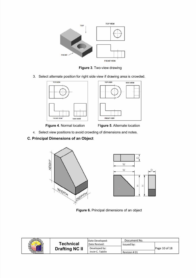
C. Principal Dimensions of an Object
Figure 3. Two-view drawing
Figure 4. Normal location Figure 5. Alternate location
Figure 6. Principal dimensions of an object
7/26/2019 Interpreting Technical Drawing
http://slidepdf.com/reader/full/interpreting-technical-drawing 11/18
TechnicalDrafting NC II
Date Developed:
Date Revised:
Document No.
Issued by:
Page 11 of 18
Developed by:
Jouie C. Tabilin Revision # 01
Width. This is a perpendicular distance between two profile planes.
Height. This the perpendicular distance between two horizontal planes
Depth. This is the perpendicular distance between two frontal planes.
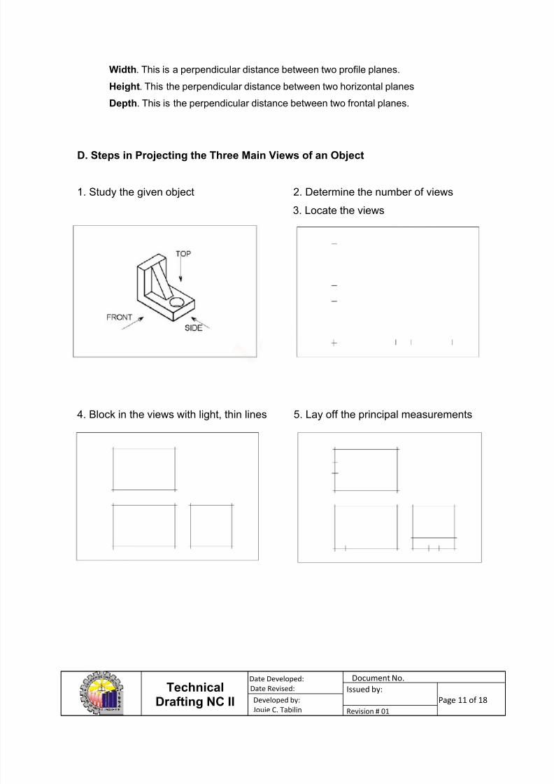
D. Steps in Projecting the Three Main Views of an Object
1. Study the given object 2. Determine the number of views
3. Locate the views
4. Block in the views with light, thin lines 5. Lay off the principal measurements
7/26/2019 Interpreting Technical Drawing
http://slidepdf.com/reader/full/interpreting-technical-drawing 12/18
TechnicalDrafting NC II
Date Developed:
Date Revised:
Document No.
Issued by:
Page 12 of 18
Developed by:
Jouie C. Tabilin Revision # 01
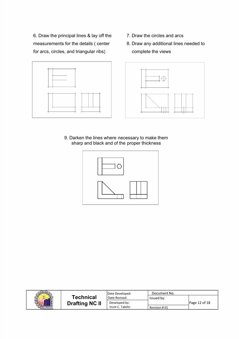
6. Draw the principal lines & lay off the
measurements for the details ( center
for arcs, circles, and triangular ribs)
7. Draw the circles and arcs
8. Draw any additional lines needed to
complete the views
9. Darken the lines where necessary to make themsharp and black and of the proper thickness
7/26/2019 Interpreting Technical Drawing
http://slidepdf.com/reader/full/interpreting-technical-drawing 13/18
TechnicalDrafting NC II
Date Developed:
Date Revised:
Document No.
Issued by:
Page 13 of 18
Developed by:
Jouie C. Tabilin Revision # 01
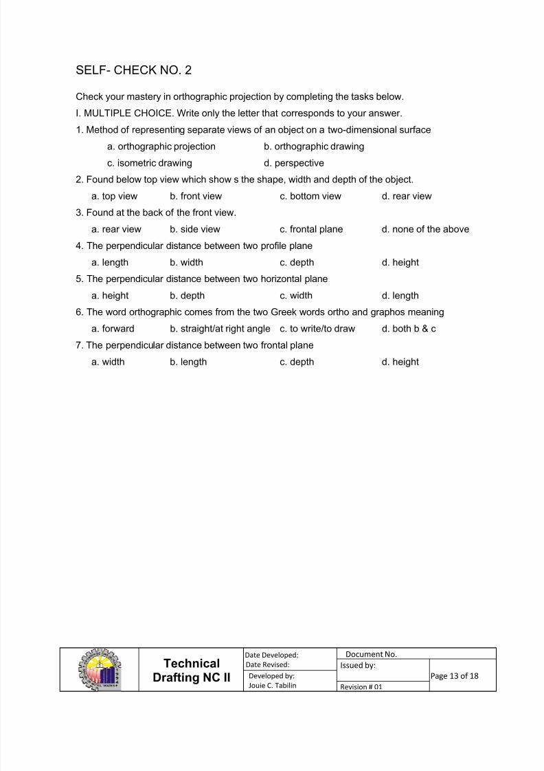
SELF- CHECK NO. 2
Check your mastery in orthographic projection by completing the tasks below.
I. MULTIPLE CHOICE. Write only the letter that corresponds to your answer.
1. Method of representing separate views of an object on a two-dimensional surface
a. orthographic projection b. orthographic drawing
c. isometric drawing d. perspective
2. Found below top view which show s the shape, width and depth of the object.
a. top view b. front view c. bottom view d. rear view
3. Found at the back of the front view.
a. rear view b. side view c. frontal plane d. none of the above
4. The perpendicular distance between two profile plane
a. length b. width c. depth d. height
5. The perpendicular distance between two horizontal plane
a. height b. depth c. width d. length
6. The word orthographic comes from the two Greek words ortho and graphos meaning
a. forward b. straight/at right angle c. to write/to draw d. both b & c
7. The perpendicular distance between two frontal plane
a. width b. length c. depth d. height
7/26/2019 Interpreting Technical Drawing
http://slidepdf.com/reader/full/interpreting-technical-drawing 14/18
TechnicalDrafting NC II
Date Developed:
Date Revised:
Document No.
Issued by:
Page 14 of 18
Developed by:
Jouie C. Tabilin Revision # 01
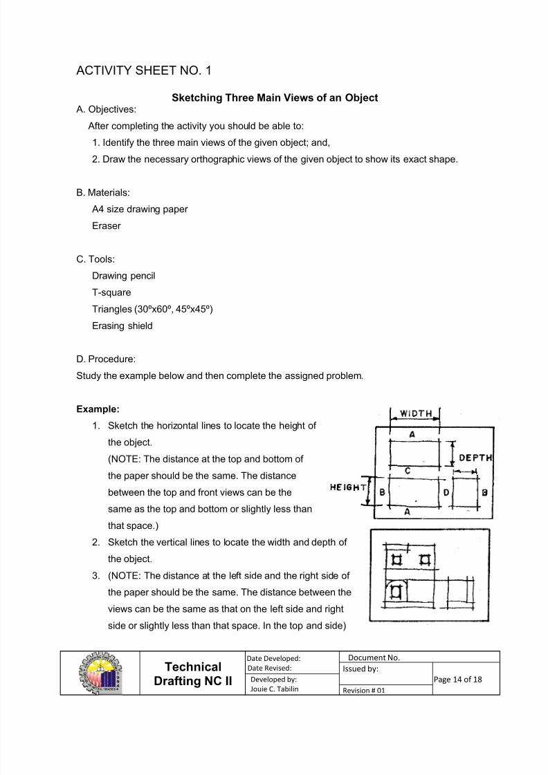
ACTIVITY SHEET NO. 1
Sketching Three Main Views of an Object A. Objectives:
After completing the activity you should be able to:1. Identify the three main views of the given object; and,
2. Draw the necessary orthographic views of the given object to show its exact shape.
B. Materials:
A4 size drawing paper
Eraser
C. Tools:Drawing pencil
T-square
Triangles (30ºx60º, 45ºx45º)
Erasing shield
D. Procedure:
Study the example below and then complete the assigned problem.
Example:
1. Sketch the horizontal lines to locate the height of
the object.
(NOTE: The distance at the top and bottom of
the paper should be the same. The distance
between the top and front views can be the
same as the top and bottom or slightly less than
that space.)
2. Sketch the vertical lines to locate the width and depth of
the object.
3. (NOTE: The distance at the left side and the right side of
the paper should be the same. The distance between the
views can be the same as that on the left side and right
side or slightly less than that space. In the top and side)
7/26/2019 Interpreting Technical Drawing
http://slidepdf.com/reader/full/interpreting-technical-drawing 15/18
TechnicalDrafting NC II
Date Developed:
Date Revised:
Document No.
Issued by:
Page 15 of 18
Developed by:
Jouie C. Tabilin Revision # 01
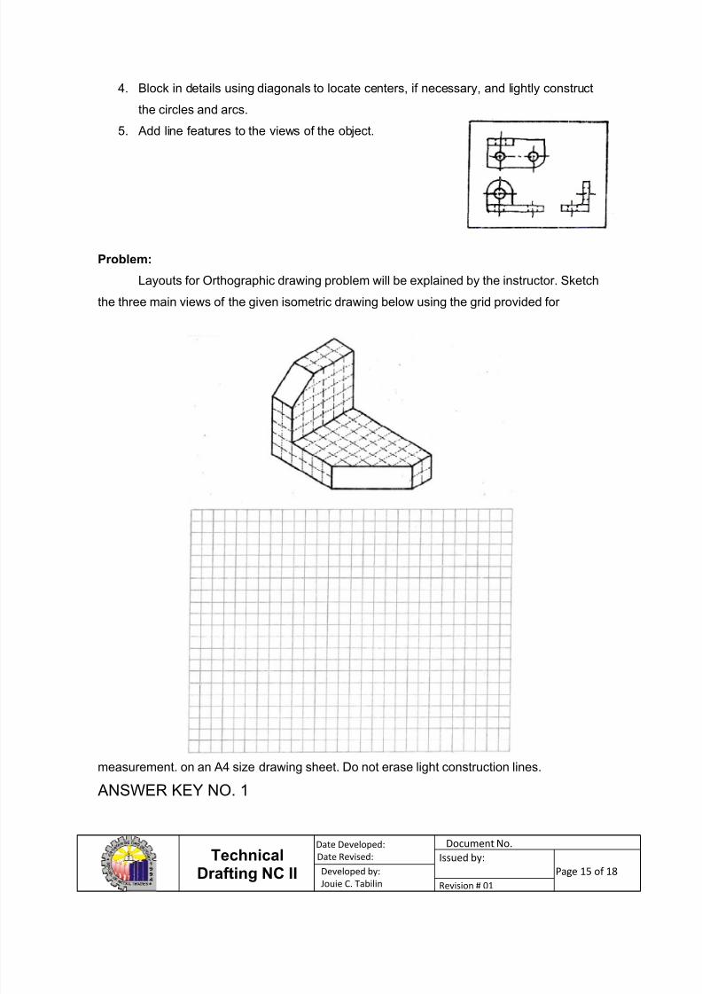
4. Block in details using diagonals to locate centers, if necessary, and lightly construct
the circles and arcs.
5. Add line features to the views of the object.
Problem:
Layouts for Orthographic drawing problem will be explained by the instructor. Sketch
the three main views of the given isometric drawing below using the grid provided for
measurement. on an A4 size drawing sheet. Do not erase light construction lines.
ANSWER KEY NO. 1

7/26/2019 Interpreting Technical Drawing
http://slidepdf.com/reader/full/interpreting-technical-drawing 16/18
TechnicalDrafting NC II
Date Developed:
Date Revised:
Document No.
Issued by:
Page 16 of 18
Developed by:
Jouie C. Tabilin Revision # 01
Check your answer with the answer key below. If you fail to get it right, refer back to
corresponding resources until you make it perfect.
1. Center line
2. Hidden line
4. Cutting-plane line
5. Object line
6. Section line
7/26/2019 Interpreting Technical Drawing
http://slidepdf.com/reader/full/interpreting-technical-drawing 17/18
TechnicalDrafting NC II
Date Developed:
Date Revised:
Document No.
Issued by:
Page 17 of 18
Developed by:
Jouie C. Tabilin Revision # 01
ANSWER KEY NO. 2
Check your answer with the answer key below. If you fail to get it right, refer back to
corresponding resources until you make it perfect.
1. A
2. C
3. A
4. B
5. A
6. D
7. C

7/26/2019 Interpreting Technical Drawing
http://slidepdf.com/reader/full/interpreting-technical-drawing 18/18
TechnicalDrafting NC II
Date Developed:
Date Revised:
Document No.
Issued by:
Page 18 of 18
Developed by:
Jouie C. Tabilin Revision # 01
RECORD OF COMPETENCE
Below are your assessment ratings:
ASSESSMENT /PERFORMANCECRITERIA YES NO
1. Components, assemblies or objects recognized
as required
2. Dimensions of the key features of the objects
depicted in the drawing correctly identified
3. Symbols used in the drawing identified and
interpreted correctly
4. Drawing checked and validated against job
requirements or equipment in accordance with
standard operating procedures