Interpretation of the behaviour of masonry arches and ...€¦ · Interpretation of the behaviour...
12
Interpretation of the behaviour of masonry arches and domes by simple models F. Palmisano DICATECh, Politecnico di Bari, Italy Abstract The prediction of the structural behaviour is of crucial importance for a good design as well as for critical validation of the results of sophisticated computer- based analyses. This is the reason why simple models are nowadays essential because they provide easy and accessible understanding of fundamental aspects of the structural response. The present work is a contribution to the search of simple models to understand the relation between Form and Structure. In this article, by using the Load Path Method, the behaviour of arches and domes, when subjected to gravitational and symmetrical loads has been analysed. Keywords: simple models, load path method, masonry structures, arch, dome. 1 Introduction Following Roca et al. [1], who sustain simple methods based on fundamental principles (e.g. limit theorems of plasticity) as still crucial to catch on the primary aspects of the structural response, this article discusses the results of a study on the use of the Load Path Method to interpret the behaviour of masonry arches and domes. The choice of the Load Path Method as an instrument to investigate structural behaviour derives from the wish to find a method that could represent the trait d’union between Structure and Architecture. The absence of a common language is one of the reasons why nowadays there is a very big gap between the Architect and the Engineer. The introduction of new materials and techniques during the Industrial Revolution and the born of the first polytechnics in the 18 th century, led to a different cultural approach to the design causing the born of different languages between architects and engineers. Structural Studies, Repairs and Maintenance of Heritage Architecture XIII 233 www.witpress.com, ISSN 1743-3509 (on-line) WIT Transactions on The Built Environment, Vol 131, © 2013 WIT Press doi:10.2495/STR130201
-
Upload
phungduong -
Category
Documents
-
view
217 -
download
0
Transcript of Interpretation of the behaviour of masonry arches and ...€¦ · Interpretation of the behaviour...

Interpretation of the behaviour of masonry arches and domes by simple models
F. Palmisano DICATECh, Politecnico di Bari, Italy
Abstract
The prediction of the structural behaviour is of crucial importance for a good design as well as for critical validation of the results of sophisticated computer-based analyses. This is the reason why simple models are nowadays essential because they provide easy and accessible understanding of fundamental aspects of the structural response. The present work is a contribution to the search of simple models to understand the relation between Form and Structure. In this article, by using the Load Path Method, the behaviour of arches and domes, when subjected to gravitational and symmetrical loads has been analysed. Keywords: simple models, load path method, masonry structures, arch, dome.
1 Introduction
Following Roca et al. [1], who sustain simple methods based on fundamental principles (e.g. limit theorems of plasticity) as still crucial to catch on the primary aspects of the structural response, this article discusses the results of a study on the use of the Load Path Method to interpret the behaviour of masonry arches and domes. The choice of the Load Path Method as an instrument to investigate structural behaviour derives from the wish to find a method that could represent the trait d’union between Structure and Architecture. The absence of a common language is one of the reasons why nowadays there is a very big gap between the Architect and the Engineer. The introduction of new materials and techniques during the Industrial Revolution and the born of the first polytechnics in the 18th century, led to a different cultural approach to the design causing the born of different languages between architects and engineers.
Structural Studies, Repairs and Maintenance of Heritage Architecture XIII 233
www.witpress.com, ISSN 1743-3509 (on-line) WIT Transactions on The Built Environment, Vol 131, © 2013 WIT Press
doi:10.2495/STR130201

Nowadays, with the widespread of very complicated works of the architecture there is a huge need to bridge the gap between architects and engineers. Maybe it can be achieved by finding a common method that should be useful to understand the structural behaviour as well as a clear and effective instrument of investigation and judgement. A method not only numerical but also geometrical that should predict calculation results disclosing the shape aspects from which it is possible to recognise the real structural behaviour. In this context, focusing the attention on masonry arches and domes, this paper aims at highlighting that the Load Path Method seems to open new prospects in the search for a common language between engineers and architects to give voice, in harmony and in a single design, to formal, aesthetical, functional and structural aspects. Even though either FEM analyses or optimisation algorithms (e.g. [2, 3]) are necessary to numerically analyse masonry structures, this article shows that simple methods, such as the Load Path Method, are sufficient to interpret the behaviour of masonry arches and domes.
2 Key features of the load path method
The Strut-and-Tie Model (STM hereafter) was originally developed by Ritter [4] for the analysis and design of reinforced concrete beams under shear. The possibility of using the STM approach for the study of masonry structural behaviour has been recently investigated (e.g. references [5–7]). Born as a method to design strut-and-tie models in reinforced concrete structures, the Load Path Method (LPM hereafter) was introduced by Schlaich et al. [8] and then developed mainly by F. Palmisano and A. Vitone (e.g. references [9–13]). Vitone [14], De Tommasi et al. [15], Palmisano et. al. [16], Palmisano and Elia [17, 18] proposed the Load Path Method to analyse also the behaviour of masonry structures. In the transfer of forces within a structure or an element, from their point of origin (S) to their ends (E), deviations in the load path direction can occur causing a thrust (H); for equilibrium to be maintained, a reactive force must be applied that is equal in magnitude and opposite in direction to this thrust (Figs. 1 and 2) The load path represents the line along which a force or a force component (more precisely: the component of a force in a chosen direction, e.g. the vertical component of a load) is carried through a structure from the point of loading to its support. The force component (F in Fig. 1) associated with a load path remains constant on its way through the structure; as a consequence of this definition, thrust H must be perpendicular to the travelling load F. The design of this load flowing through the structure can be approximated by polygonal lines in which there are thrusts in every deviation node. It follows that, according to the model, the structure will be crossed by fluxes in compression (dashed lines), when loads travel in the same direction of their path, and by fluxes in tension (continuous lines) along which loads go in the opposite direction with respect to their path (Fig. 2). According to the classical
234 Structural Studies, Repairs and Maintenance of Heritage Architecture XIII
www.witpress.com, ISSN 1743-3509 (on-line) WIT Transactions on The Built Environment, Vol 131, © 2013 WIT Press

theory, the basic principles of the Load Path Method are the respect of both equilibrium and consistency. Thrusts in deviation nodes are necessary in order to respect equilibrium and every path is possible if it is in equilibrium.
Figure 1: Load Path (LP) and Strut-and-Tie model (STM).
Figure 2: Load path: symbols.
Among infinite paths in equilibrium, loads have to choose the one in which their vectors invest the minimum quantity of strain energy (D), that is the only one both consistent and in equilibrium. The total invested strain energy is
12 V
D dV= ∫σε (1)
Structural Studies, Repairs and Maintenance of Heritage Architecture XIII 235
www.witpress.com, ISSN 1743-3509 (on-line) WIT Transactions on The Built Environment, Vol 131, © 2013 WIT Press

where V is the integration domain, σ and ε are the stress and the strain vector respectively. Along a generic path, that is polygonal in this model, the calculus of the invested strain energy (D) is simplified in the summation of the terms which are relative to each side of the truss: i
iD D= ∑ (2)
where i is the generic side of the load path. For instance, if linear elastic constitute laws for materials are assumed as well as constant transversal section of each side, the elementary strain energy Di is
12i i i iD N l ε= (3)
where i is the generic side of the load path, Ni is the intensity of the vector that bears the travelling load on that side, li is the length of the generic side and εi is the mean strain on that side. In the assumption of linear elastic constitute laws for materials with Young’s Modulus equal to E, if the transversal section of a side is linearly variable from A(1)
i to A(2)i (e.g. half of a bottle-shaped strut) the elementary strain energy Di is
( )
2 (1)
(2)(1) (2)
12
i i ii
ii i
N l AD Ln
AE A A
= −
(4)
From figure 2 it is possible to notice that the relation between the travelling load F and its vector N is
sin
FNθ
= (5)
where θ is the inclination of the path. If θ decreases, N increases; this means that the condition with θ nil is not consistent because it will produce an infinite value of N and, hence, of the strain energy D. The consequence of this consideration is that a travelling load cannot move orthogonally to itself. The only possibility to move in the direction orthogonal to the travelling load is to follow a path composed by inclined descending and ascending sides.
3 The masonry arch and dome behaviour
In this paragraph, the interpretation of the masonry arch and dome behaviour using the Load Path Method is presented; the method immediately exhibits the correlation between form (geometry) and structure (distribution of loads and thrusts). For the sake of simplicity, but without any loss of generality, the case of arches and domes geometrically symmetrical and symmetrically loaded only with vertical loads is considered. According to Heyman [19] the behaviour of a masonry arch can be examined in the light of three simplified assumptions, each one of which is not strictly true and must be hedged with qualifications, and which must in any case be tested in the light of a contradictory experience with a particular building. The three assumptions are that:
236 Structural Studies, Repairs and Maintenance of Heritage Architecture XIII
www.witpress.com, ISSN 1743-3509 (on-line) WIT Transactions on The Built Environment, Vol 131, © 2013 WIT Press

(i) masonry has no tensile strength; (ii) stresses are so low that masonry has effectively an unlimited compressive
strength; (iii) sliding failure does not occur.
According to LPM, the three assumptions mean respectively that [16]: (i) loads and thrusts have to remain inside the arch and can follow only paths
in compression; (ii) inside the arch the path of loads and thrusts can ‘touch’ the edges of the
structure without implying the arch rupture; (iii) local ruptures involve neither an appreciable change of the shape of the
load and thrust paths nor local discontinuities such as slippage of two faces of the same cross section.
Figure 3 shows the interpretation of the arch as the path of vertical loads.
Figure 3: The arch as path of vertical loads.
According to LPM, in every node Oi, Fi deviates and applies a thrust to the structure: ( ) coti i i iH F F ϑ=
(6) For equilibrium to be maintained (i.e. to make possible the Fi deviation), ∑Fj, coming from the top, must deviate in Oi of δi, increasing the inclination angle from θi+1 to θi, and a thrust equal in value (but opposite in direction) to the Fi one must be applied (Fig. 3b):
( )11 1
cot cotn n
i j j i ii i
H F F ϑ ϑ++ +
= −
∑ ∑ (7)
Structural Studies, Repairs and Maintenance of Heritage Architecture XIII 237
www.witpress.com, ISSN 1743-3509 (on-line) WIT Transactions on The Built Environment, Vol 131, © 2013 WIT Press

Because of the equilibrium of these two thrusts, it is possible that loads go from their application points to the imposts only by path in compression. Eqn (7) analytically shows what Figure 3 exhibits graphically: the line of the ‘possible’ (i.e. in equilibrium) load paths is strictly related to the intensity and distribution of loads Fi. It is also possible to interpret the arch as the path of the thrust H (Fig. 4). In this case the travelling load H does not change (if every Fi is vertical). In every node the thrust path (from the impost to the crown) deviates of δi. This is possible (i.e. in equilibrium) because in every node Oi, the vertical thrust Vi (directed from the bottom to the top) of H is equilibrated by the load Fi which is equal in value but opposite in direction.
Figure 4: The arch as path of the thrust.
A dome (Fig. 5) can be seen as a system of meridian arches joined by the parallel circles. The arches draw the paths of the vertical loads while the parallel circles draw the paths of the unbalanced thrusts. Differently from the arches, in a dome the equilibrium of the thrusts in every node is always possible because of the presence of the parallels. The difference Hp(Fi) between the thrust of Fi and that of ∑Fj, enters the parallel and find equilibrium thanks to the axial symmetry. Figure 5 shows that the shape of a dome has a direct influence on the type of the path of the unbalanced thrusts. At the top part of the dome the thrust of Fi is bigger than that ∑Fj for two reasons: firstly the deviation θi of Fi is larger than that (δi) of ∑Fj and secondly the intensity of ∑Fj is low. This implies that Hp(Fi) is centripetal and,
238 Structural Studies, Repairs and Maintenance of Heritage Architecture XIII
www.witpress.com, ISSN 1743-3509 (on-line) WIT Transactions on The Built Environment, Vol 131, © 2013 WIT Press

consequently, it generates a compression action in the parallel. Just the opposite happens at the bottom part of the dome. However, the tensile forces towards the base are inadmissible for the above mentioned assumption of no-tensile strength. Actually two explanations of the dome equilibrium are possible:
• the bottom tensile action is so low (because of the thickness of the dome) to be compatible with the masonry tensile strength;
• due to the high tensile action the bottom part of the dome separates into ‘slices’ divided by meridian cracks but equilibrium is maintained because every slice starts to behave like a two-dimensional arch.
Figure 5: Paths of loads and thrusts in a dome.
Regarding the last consideration it is worth noting that many domes show precisely such meridian crack patterns [20]. A celebrated account was given by Poleni [21], who reported on the cracks apparent in the dome of St Peter’s Basilica in Rome, nearly 200 years after its completion. Starting from the observation that the cracks had already divided the dome into meridian slices (‘orange slices’), Poleni showed that the dome of St Peter’s Basilica was safe in its cracked state because he demonstrated that every slice, behaving like an arch, was in equilibrium. Even though Poleni concluded that the observed cracking was not critical, he agreed with an earlier recommendation that further encircling ties should be provided.
Structural Studies, Repairs and Maintenance of Heritage Architecture XIII 239
www.witpress.com, ISSN 1743-3509 (on-line) WIT Transactions on The Built Environment, Vol 131, © 2013 WIT Press
4 The masonry dome with no ring behaviour
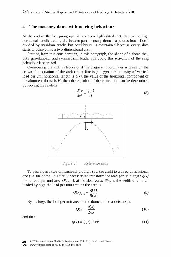
At the end of the last paragraph, it has been highlighted that, due to the high horizontal tensile action, the bottom part of many domes separates into ‘slices’ divided by meridian cracks but equilibrium is maintained because every slice starts to behave like a two-dimensional arch. Starting from this consideration, in this paragraph, the shape of a dome that, with gravitational and symmetrical loads, can avoid the activation of the ring behaviour is searched. Considering the arch in figure 6, if the origin of coordinates is taken on the crown, the equation of the arch centre line is y = y(x), the intensity of vertical load per unit horizontal length is q(x), the value of the horizontal component of the abutment thrust is H, then the equation of the centre line can be determined by solving the relation
2
2
( )d y q xHdx
= (8)
Figure 6: Reference arch.
To pass from a two-dimensional problem (i.e. the arch) to a three-dimensional one (i.e. the dome) it is firstly necessary to transform the load per unit length q(x) into a load per unit area Q(x). If, at the abscissa x, B(x) is the width of an arch loaded by q(x), the load per unit area on the arch is
( )( )( )arch
q xQ xB x
= (9)
By analogy, the load per unit area on the dome, at the abscissa x, is
( )( )2q xQ x
xπ= (10)
and then ( ) ( ) 2q x Q x xπ= ⋅ (11)
240 Structural Studies, Repairs and Maintenance of Heritage Architecture XIII
www.witpress.com, ISSN 1743-3509 (on-line) WIT Transactions on The Built Environment, Vol 131, © 2013 WIT Press

From eqns (8) and (11) it is possible to obtain the centre line equation of an arch that, by its rotation about the Y axis, generates the dome with no ring behaviour:
2
2
1 ( )2d y Q xx Hdx
π= (12)
An important application is the case of a dome subjected to its own weight. If the dome has thickness t and unit weight ρ, then ( )q x dx t dSρ⋅ = ⋅ ⋅ (13) where dS is the elementary area. According to the first Pappus’s centroid theorem, the surface area S of a surface of revolution generated by rotating a plane curve γ of an angle α about the Y axis is GS x lγα= ⋅ ⋅ (14)
where lγ is the length of the curve γ
2
0
1x dyl dx
dxγ = + ∫ (15)
and xG is the abscissa of the centroid of γ
2
0
2
0
1
1
x
G x
dyx dxdx
xdy dxdx
⋅ + = +
∫
∫
(16)
Substituting (15) and (16) into (14) and taking into account that in the examined case α=2π, it is possible to obtain
2
0
2 1x dyS x dx
dxπ = ⋅ ⋅ +
∫ (17)
and then
2
2 1dS dyxdx dx
π = ⋅ ⋅ +
(18)
Finally from (13) and (18) the vertical load per unit horizontal length is
2
( ) 2 1 dyq x t xdx
π ρ = ⋅ ⋅ ⋅ ⋅ +
(19)
This equation could be directly obtained from (11) considering that in the case under question, if ds is the elementary length of the centre line, then
( ) ( )
( ) ( )2 2 2
1
ds dsQ x Q s tdx dx
dx dy dyt tdx dx
ρ
ρ ρ
= = ⋅ =
+ = ⋅ = ⋅ ⋅ +
(20)
Structural Studies, Repairs and Maintenance of Heritage Architecture XIII 241
www.witpress.com, ISSN 1743-3509 (on-line) WIT Transactions on The Built Environment, Vol 131, © 2013 WIT Press

From relations (8) and (19) it is possible to obtain the centre line equation of an arch that, by its rotation around the Y axis, generates the dome with no ring behaviour and subjected to its own weight:
22
2
2 1d y t dyxH dxdx
π ρ⋅ ⋅ = ⋅ ⋅ +
(21)
Assuming g(x)=dy/dx, relation (21) becomes
2
( ) 2
1 ( )
dg x t x dxHg x
π ρ⋅ ⋅= ⋅ ⋅
+ (22)
that can be integrated obtaining
( )( )2
11
2sinh2
− ⋅ ⋅= ⋅ +
t xg x CH
π ρ (23)
and then
2
12sinh
2dy t x Cdx H
π ρ ⋅ ⋅= ⋅ +
(24)
where C1 is a constant. Equation (24) has not a closed-form solution and then numerical methods are needed to find the centre line equation for the case under study. Figure 7 shows the comparison between the centre line of a dome without ring behaviour, calculated by numerical integration of equation (24), and that of a hemispherical dome having span and rise equal to 60 m and 30 m respectively. The difference between the two lines clearly shows that in the hemispherical dome, ring behaviour is necessary for equilibrium to be maintained.
0
5
10
15
20
25
30
35
-35 -30 -25 -20 -15 -10 -5 0 5 10 15 20 25 30 35X [m]
Y [m] dome w/o ring behaviour
hemispherical dome
Figure 7: Comparison between the centre line of a dome without ring behaviour and that of a hemispherical dome (span = 60 m; rise = 30 m).
242 Structural Studies, Repairs and Maintenance of Heritage Architecture XIII
www.witpress.com, ISSN 1743-3509 (on-line) WIT Transactions on The Built Environment, Vol 131, © 2013 WIT Press

5 Conclusions
In this study, starting from the interpretation of the arch behaviour, the Load Path Method has been used to analyse the behaviour of masonry domes. Moreover analytical relations to find the shape of the dome that, with gravitational and symmetrical loads, can avoid the activation of the ring behaviour have been obtained. The aim of this work is to show that the Load Path Method can be an effective instrument to bridge the gap between engineers and architect because it seems to conciliate successfully the necessity to get a numerical solution without losing touch with the perception of the synthesis of physical structural behaviour.
References
[1] Roca, P., Cervera, M., Gariup, G. and Pelà, L.,·Structural Analysis of Masonry Historical Constructions. Classical and Advanced Approaches’, Archives of Computational Methods in Engineering, 3 (17), pp. 299–325, 2010.
[2] Mezzina, M., Palmisano, F. and Raffaele, D., The design of r.c. bridge deck subjected to horizontal actions by strut-and-tie model. Bridge Maintenance, Safety, Management and Life-Cycle Optimization (proc. of the 5th International Conference on Bridge Maintenance, Safety and Management – IABMAS 2010, Philadelphia, Pennsylvania, USA, July 11-15 2010), edited by D.M. Frangopol, R. Sause, C.S. Jusko, Taylor and Francis Group, London, UK, pp. 2390-2397, 2010.
[3] Mezzina, M., Palmisano, F. and Raffaele, D., Designing simply supported R.C. bridge decks subjected to in-plane actions: Strut-and-Tie Model approach. Journal of Earthquake Engineering, Taylor and Francis, London, UK, Vol. 16, n. 04, pp. 496-514, 2010.
[4] Ritter, W., Die Bauweise Hennebique. Schweizerische Bauzeitung, 7 (33), pp. 59-61, 1899.
[5] Ganz, H.R. and Thürlimann, B., Strength of brick walls under normal force and shear. Proc. 8th International Symposium on load bearing brickwork, London, UK, pp. 27–29, 1983.
[6] Roca, P., Assessment of masonry shear walls by simple equilibrium models. Construction and Building Materials, 4 (20), pp. 229–238, 2006.
[7] Roca, P., Viviescas, A., Lobato, M., Díaz, C. and Serra, I., Capacity of Shear Walls by Simple Equilibrium Models. International Journal of Architectural Heritage, 4-5 (5), pp. 412-435, 2011.
[8] Schlaich, J., Schafer, K. and Jennewein, M., Toward A Consistent Design of Structural Concrete. PCI Journal, 32 (3), pp. 74-150, 1987.
[9] Palmisano, F., Vitone, A. and Vitone, C., Form and Structure. The Rome Auditorium: load path method (LPM). D’Architettura, 18, pp.168-173, 2002.
[10] Palmisano, F., Vitone, A. and Vitone, C., From load path method to classical models of structural analysis. System-based Vision for Strategic
Structural Studies, Repairs and Maintenance of Heritage Architecture XIII 243
www.witpress.com, ISSN 1743-3509 (on-line) WIT Transactions on The Built Environment, Vol 131, © 2013 WIT Press

and Creative Design, Vol. 1, F. Bontempi ed., Balkema, Rotterdam, the Netherlands, pp. 589-596, 2003.
[11] Palmisano, F., Form and structure in the harmonious complexity of the building process: from conceptual design to detailing in some reinforced concrete works. Structural Concrete, 6 (3), pp. 122-130, 2005.
[12] Palmisano, F., Vitone, A., Vitone, C. and Vitone, V., Collapse of the Giotto Avenue Building in Foggia. Structural Engineering International, IABSE, Zurich, Switzerland, Vol. 17, n. 2, pp. 166-171, 2007.
[13] Palmisano, F., Vitone, A. and Vitone, C., A first approach to optimum design of cable supported bridges using load path method. Structural Engineering International, 18 (2), pp. 412-420, 2008.
[14] Vitone, C., Il Load Path Method per il restauro strutturale delle opere murarie, M.S. thesis, Politecnico di Bari, Bari, Italy, 2001.
[15] De Tommasi, G., Monaco, P. and Vitone, C., A first approach to load path method on the masonry structures behaviour. Structural Studies, Repairs and Maintenance of Heritage Architecture VIII, C.A. Brebbia ed., WIT press, Southampton, UK, pp. 287-296, 2003.
[16] Palmisano, F., Vitone, A. and Vitone, C., Load path method in the interpretation of the masonry vault behaviour. Structural Studies, Repairs and Maintenance of Heritage Architecture IX, C.A. Brebbia and A. Torpiano eds., WIT press, Southampton, UK, pp. 155-167, 2005.
[17] Palmisano, F. and Elia, A., Masonry buildings subjected to foundation settlements due to landslide: a preliminary study on the interpretation of structural behaviour using load path method. Structural Studies, Repairs and Maintenance of Heritage Architecture XI, edited by C.A. Brebbia, WIT press, Southampton, United Kingdom, pp. 141-150, 2009.
[18] Palmisano, F. and Elia, A., Analysis of the structural behaviour of masonry buildings subjected to landslide by using the Load Path Method, International Journal of Earth Sciences and Engineering, Vol. 06, n. 01, 2013.
[19] Heyman, J., The masonry arch, Chichester, Ellis Horwood Limited, 1982. [20] Heyman, J., The stone skeleton – structural engineering of masonry
architecture, Cambridge, Cambridge University Press, 1995. [21] Poleni, G., Memorie istoriche della gran cupola del Tempio Vaticano,
Padova, 1748.
244 Structural Studies, Repairs and Maintenance of Heritage Architecture XIII
www.witpress.com, ISSN 1743-3509 (on-line) WIT Transactions on The Built Environment, Vol 131, © 2013 WIT Press