INTERPLAY OF CONTAINER PORT CRANES AND QUAY-WALLS DURING EARTHQUAKE SHAKING · INTERPLAY OF...
10
1 INTERPLAY OF CONTAINER PORT CRANES AND QUAY-WALLS DURING EARTHQUAKE SHAKING Rallis KOURKOULIS 1 , Fani GELAGOTI 2 , Marianna LOLI 3 and George GAZETAS 4 ABSTRACT Despite the great reliance of modern societies on the operability of commercial ports, the latter mainly depend on aged quay walls built according to obsolete seismic codes. Moreover, although several seismic design guidelines exist for port structures, provisions regarding the seismic performance of very sensitive components of container terminals such as cranes are rather limited. Although the latter are quite vulnerable to differential displacement of their supports, they are typically designed as rigid frames with little or no seismic detailing neglecting their potential interplay with quay-walls during earthquake shaking. In view of the above, this paper presents a parametric study involving nonlinear FE numerical analyses of the entire soil-wall-crane interacting system. It is shown that although the inertial response of the wall is usually out-of-phase with the crane, the seaward displacement of the former may impose kinematically-induced loading on the crane legs producing distortion or even derailment. In terms of current quay-wall design practice, it is shown that replacing the crane with two constant vertical forces at the locations of its two legs during seismic analysis of port quay-walls is an acceptably conservative practice in case of operational-level earthquakes but in case of design-level shaking the crane may exert an additional seawards loading on the wall due to redistribution of internal shear forces on its sea-side legs. INTRODUCTION The latest advances in port and maritime industry have redefined the role of harbor facilities as a benchmark for the national economy. Therefore the direct and indirect losses associated with the obstruction of the normal function of a port facility are extremely high and may generate major regional, national, and even world-wide economic impact. Note that a 2002 10-day labor lockout at west coast ports in the USA cost the country’s economy an estimated $1 billion daily ( Caltrade, 2008). Experience has shown that port facilities may be particularly susceptible to earthquake related hazards. The 1989 M w 6.9 Loma Prieta, California, earthquake caused considerable damage to terminal facilities at the Port of Oakland (Werner, 1998; EERI, 1990), the most severe of which was at the 7 th Street Terminal. The inboard crane rail sustained substantial damage as a result of differential settlements rendering several of its major cranes immobile after the earthquake. The striking M w 7.2 Kobe earthquake in 1995 devastated the Industrial Container Terminal of the Port of Kobe (Japan), causing tens of cranes along the wharf to collapse. Extensive damage was also experienced by the 1 Post Doctoral Researcher, NTUA, Athens, [email protected] 2 Post Doctoral Researcher, NTUA, Athens, [email protected] 3 PhD Candidate, NTUA, Athens, [email protected] 4 Professor, NTUA, Athens, [email protected]
Transcript of INTERPLAY OF CONTAINER PORT CRANES AND QUAY-WALLS DURING EARTHQUAKE SHAKING · INTERPLAY OF...
1
INTERPLAY OF CONTAINER PORT CRANES AND QUAY-WALLS
DURING EARTHQUAKE SHAKING
Rallis KOURKOULIS1, Fani GELAGOTI
2, Marianna LOLI
3 and George GAZETAS
4
ABSTRACT
Despite the great reliance of modern societies on the operability of commercial ports, the latter mainly
depend on aged quay walls built according to obsolete seismic codes. Moreover, although several
seismic design guidelines exist for port structures, provisions regarding the seismic performance of
very sensitive components of container terminals such as cranes are rather limited. Although the latter
are quite vulnerable to differential displacement of their supports, they are typically designed as rigid
frames with little or no seismic detailing neglecting their potential interplay with quay-walls during
earthquake shaking. In view of the above, this paper presents a parametric study involving nonlinear
FE numerical analyses of the entire soil-wall-crane interacting system. It is shown that although the
inertial response of the wall is usually out-of-phase with the crane, the seaward displacement of the
former may impose kinematically-induced loading on the crane legs producing distortion or even
derailment. In terms of current quay-wall design practice, it is shown that replacing the crane with two
constant vertical forces at the locations of its two legs during seismic analysis of port quay-walls is an
acceptably conservative practice in case of operational-level earthquakes but in case of design-level
shaking the crane may exert an additional seawards loading on the wall due to redistribution of
internal shear forces on its sea-side legs.
INTRODUCTION
The latest advances in port and maritime industry have redefined the role of harbor facilities as
a benchmark for the national economy. Therefore the direct and indirect losses associated with the
obstruction of the normal function of a port facility are extremely high and may generate major
regional, national, and even world-wide economic impact. Note that a 2002 10-day labor lockout at
west coast ports in the USA cost the country’s economy an estimated $1 billion daily (Caltrade,
2008). Experience has shown that port facilities may be particularly susceptible to earthquake related
hazards. The 1989 Mw6.9 Loma Prieta, California, earthquake caused considerable damage to terminal
facilities at the Port of Oakland (Werner, 1998; EERI, 1990), the most severe of which was at the 7th
Street Terminal. The inboard crane rail sustained substantial damage as a result of differential
settlements rendering several of its major cranes immobile after the earthquake. The striking Mw7.2
Kobe earthquake in 1995 devastated the Industrial Container Terminal of the Port of Kobe (Japan),
causing tens of cranes along the wharf to collapse. Extensive damage was also experienced by the
1 Post Doctoral Researcher, NTUA, Athens, [email protected]
2 Post Doctoral Researcher, NTUA, Athens, [email protected]
3 PhD Candidate, NTUA, Athens, [email protected]
4 Professor, NTUA, Athens, [email protected]

2
main port in Port-au-Prince during the 2010 Mw7 Haiti earthquake, inhibiting the delivery of supplies
due to the toppling of cranes.
In view of the above, it is clear that in order to enhance the coastal resilience against earthquake
action, it is of primary interest to realistically estimate the vulnerability of port facilities. This task
becomes particularly challenging when considering that modern terminals are extended waterfront
structures which comprise a variety of highly heterogeneous but interdependent components. Yet,
according to the current state of practice the vulnerability assessment is tackled on an element by
element basis usually ignoring the potential interplay between the elements at risk. For instance,
although several seismic design guidelines exist for port structures (e.g ASCE, 2012; Port of Long
Beach, 2009; DOD 2005; Port of L.A., 2004), provisions regarding the seismic performance of cranes
is rather limited. Although modern codes require that cranes are not to be damaged by an operating
level seismic event, and should not collapse under the design level earthquake, no guidelines are
provided for how to ensure these performance requirements.
This neglect is warranted by the following three arguments : (i) being very flexible structures
(their fundamental period is estimated at T=1.5 – 1.8s) the cranes are expected to be less vulnerable to
standard seismic shaking (ii) their structural elements are typically overdesigned to guarantee safe
heavy lifting, thus they are not expected to fail due to vibratory motion alone (iii) at a rare case of an
extreme earthquake shaking they are allowed to uplift (i.e detach from the rail), thus being protected
from excessive inertia loading.
On the other hand, cranes are indeed very sensitive components of container terminals,
characterized by quite strict deformation limitations: typically designed as rigid frames with little or
no seismic detailing, and fabricated from thin welded shapes, they are non-redundant structures, and as
such they are vulnerable to differential displacement of their supports. The latter may be due to
settlement, sliding or rotation of the quaywall in response to ground shaking even when subjected to
moderate earthquakes. [e.g. Pitilakis & Moutsakis 1989; Egan et al 1992; Iai et al 1994; Sugano et al
1999; Dakoulas & Gazetas 2008; Elnashai et al. 2010]. In other words, cranes could become useless
even if the quay-walls deformations remain acceptable.
While this is certainly an issue, little attention has been drawn so far on the response of the
coupled crane on a quay-wall system during seismic shaking. Within this context, this paper attempts
to assess:
(a) The effect of the existence of a crane on the seismic response of quay-walls and vice-versa
(b) The role of ground motion on the response of both systems
(c) The adequacy of existing analysis techniques in describing the actual soil-wall-crane system.
To address the above issues, a parametric study has been conducted involving nonlinear FE numerical
analyses of the entire soil-wall-crane interacting system as explained in the ensuing.
SEISMIC RESPONSE OF CRANES: NUMERICAL MODELING AND VALIDATION
Several investigators have studied the earthquake response of cranes either analytically or
experimentally. They all agree that, when subjected to strong shaking the landside leg of the crane
uplifts due to its lower axial load and displaces seaward. Yet the exact characteristics of the rocking
response are strongly dependent on the particular details of the ground motion. Three distinct phases
of response are regognised (Fig. 1c):
During the 1st Phase, the structure sways due to seismic load. This is followed by a 2
nd Phase
during which the landside wheels start sliding due to considerable reduction of their axial load (and
hence reduced friction on their base. Finally, a 3rd
Phase appears once the total weight of the structure
has practically been assumed by the seaside legs, leading to uplifting of the landside legs. Depending
on the characteristics of the earthquake, after the 3rd
Phase, the leg may either land safely back to their
original position or derail.
Crane subjected to monotonic push-over loading
Prior to proceeding to the soil-wall-crane interaction analyses, the crane model response is validated as
to its ability to describe these phases when subjected to monotonically imposed push-over loading.
Following the recommendation of Sugano et. al. (2008) the crane has been modeled as a frame

R. Kourkoulis, F. Gelagoti, M. Loli and G.Gazetas 3
structure combined with a lumped mass on the center of gravity of the original structure (Fig. 1b).
Mass-less elastic beam elements are used for the modeling of legs, while a rigid beam is used to
simulate the both the girder and the connecting beam between the girder and the lumped mass.
The result of the push-over test when the crane is subjected to sea-wards displacement (positive
displacements indicate sea-wards movement) is presented in Figure 1d, and all three phases of
response (previously identified) are evident. Observe that during phase 2, sliding does not occur at a
unique value of acceleration as would be expected for the analogue of a sliding block but it rather
keeps increasing before uplifting takes place. This is due to the fact that the crane-leg is part of a frame
structure where re-distribution of internal forces takes place constantly during loading resulting in
varying shear and axial force (i.e. friction) at its base. It is also worth noting that, due to the crane
geometry, the response is strongly asymmetric and therefore sliding and uplifting may also occur
when loading in the opposite direction (landwards), yet at significantly greater accelerations.
k=3EI/l3
Rigid elements
Simple support : no resistance to uplift
contact elements allowing sliding/detachment
l
m
h d1 d2 Flexible beams:
(a) (b)
-0.5
-0.3
-0.1
0.1
0.3
0.5
-1.2 -0.8 -0.4 0 0.4 0.8 1.2
P/mg
δ : m
Phase A
Phase B
Phase C
Phase A : Portal sway
P+
Phase B: sliding of the Land-side Leg
P+ P+
(c)
(d)
Figure 1. (a) A typical crane structure (b) Numerical modeling of the crane using beam elements and lumped
mass (c) The three phases of response of a crane subjected to monotonically increasing lateral loading (d) The
dimensionless horizontal force vs horizontal displacement curve produced when subjecting the numerical model
of the crane to lateral push-over loading

4
MODEL DESCRIPTION AND CONSTITUTIVE MODELING
Problem Geometry and Soil Properties
The general dimensions and soil conditions of the problem to be analyzed have been inspired by an
existing container port-facility in an earthquake-prone area of southern Europe. The configuration of
the fully coupled model is portrayed in Figure 2a while the soil profile is described in Table 1. A
symmetrical model has been constructed in order to simultaneously examine the effect of wall
orientation with respect to the record (i.e. record polarity). Two complementary models are also
analyzed ( Fig 2b,c). These are: (i) a level ground model, where the dynamic response of the crane is
examined independently from the quaywall response and (ii) a plain quay-wall model in which the
crane has been replaced by 2 point loads (one at each crane leg); this type of analysis is adopted by
conventional seismic analysis of quay-walls.
Analysis Methodology and Numerical Modeling
The problem is analyzed utilizing the ABAQUS finite element (FE) algorithm under plane-strain
conditions, with due consideration to material (soil and superstructure) and geometric (sliding,
uplifting) nonlinearities. Soil and crane footings are modeled with quadrilateral continuum elements,
while elastic beam elements were used for the crane. To allow for detachment and sliding at the
foundation-soil interface, appropriate interface elements (with constant μ equal to 0.7) have been
utilized. The lateral boundaries of the model are free to move horizontally so as to realistically
reproduce the free-field kinematic soil response. Ground shaking is in all cases imposed at the bottom
of the models while properly calculated dashpot elements are ensuring the elimination of reflections
on the base.
(a)
(b)
Constant V load [kN/m]
l1+l2
(c)
Fully coupled FE analysis
Level ground FE analysis Conventional Approach
Figure 2. Plane Strain Finite element models. (a) The fully coupled soil-wall-crane model (b) A crane on level-
ground model (c) Soil-wall model where the crane has been replaced by two vertical forces at the location of its
two rails.
Soil elements obey to a simple elasto-plastic constitutive model with Mohr-Coulomb failure
criterion. In order to effectively account for stiffness degradation due to straining, 1-D equivalent
linear analyses have been initially performed providing the appropriate secant stiffness moduli to be
used in the subsequent 2-D analyses. The actual soil behavior in coastal areas such as port will
undeniably be affected by negative or positive pore pressures generation. The extremely complex

R. Kourkoulis, F. Gelagoti, M. Loli and G.Gazetas 5
effect of dynamic pore pressures on the response of the quay-wall has been highlighted by several
researchers. Among them, Dakoulas and Gazetas (2008) have shown that during shaking both positive
and negative excess pore water pressures may develop behind the wall depending on its oscillatory
motion; these excess (dynamic) pressure increments may result in zero, or even negative, net pore
water pressures. However, at this stage focus is on the identification of the mechanisms governing the
wall-crane interaction under seismic loading –a quite complex phenomenon in itself. Hence, in order
to reduce complexity, soil has at this stage been assumed to be dry acknowledging that consideration
of pore-pressures would alter the actual stresses acting on the wall but not the crane-wall interaction
mechanism.
Table 1. The assumed soil profile
Depth : m Description VS : m/s Eo : MPa Strenth parameters
[φ: degrees, c : kPa]
0- 15 Backfill 150-200 120-220 [32o, 0]
15-25 Foundation layer 250 350 [35o, 2]
25-35 Lower stratum 250-300 350-500 [35o, 5]
-0.4
-0.2
0
0.2
0.4
0 5 10 15 20
aFF [g]
t [s]
pga = 0.36 g a [g]
δ [m]
-0.5
-0.25
0
0.25
0.5
-1.2 -0.6 0 0.6 1.2
Figure 3. The Imperial Valley record used as excitation motion (left). The dynamic acceleration-displacement
loop produced at the crane’s center of mass when subjected to the Imperial Valley record (right).
SEISMIC RESPONSE OF THE CONTAINER CRANE: EFFECT OF QUAY-WALL
The seismic response of the crane is first evaluated by subjecting the model (of the crane on a level
ground) to a moderately strong design-level earthquake, i.e. the Imperial Valley time history (recorded
during the Mw=6.4 earthquake of 1979) whose PGA is equal to 0.36g (Fig. 3a). The crane response is
presented in terms of acceleration-displacement plot (Fig. 3b) compatible with the previously shown
monotonic-response curve. As evidenced by the plot, the shaking is sustained by the structure with no
uplifting but rather some limited sliding, as the produced curve slightly enters the sliding-dominated
region of the monotonic curve.
The effect of the wall on the crane’s response is demonstrated in Figure 4, which refers to the
most detrimental case, i.e. the response of the left crane. As expected, the wall keeps accumulating
outward displacement during shaking (Fig. 4a); observe that at around t =6.3 s, the wall experiences a
quite instantaneous displacement reflected in the form of a spike on the plot which apparently is
provoked by the main pulse of the time history (recall Fig. 3a). At this very instant, the axial force on
the left (land-side) leg of the crane is taking an instantaneous minimum (due to flexural oscillation);
this results in reduced shear resistance on the leg base which is subsequently rapidly “dragged”
rightwards (Fig. 4b) as a consequence of the wall’s displacement. The mechanism is demonstrated in
Fig. 4c). Observe that although the crane oscillation continues well after that instant, the experienced
displacement at the left foot is not recovered. It is worth noting that in the opposite crane (right part of
the model) the pulse actually “pushes” the wall inwards thereby being practically beneficial for the
response of the crane too.
The structural distress of the crane is evaluated in terms of acceleration and drift time-histories
depicted in Fig. 5, which compares the response when founded on the quay-wall with that when lying

6
on level ground. Interestingly, the experienced acceleration on the center of mass of the crane is
curtailed between 6 and 7s with respect to the level ground conditions due to the kinematically
imposed sliding identified previously. This means that sliding takes places before the crane
experiencing the sliding acceleration of 0.23g discussed previously. Indeed, sliding does occur in level
ground conditions too (Fig. 5b) but, the “dragging’-induced displacement results in an additional 13cm
of outwards displacement rising the total Δx value to 23cm which corresponds to derailment of the
crane.
δu1 : m
at t=6.3 s
δu1
α
0
0.05
0.1
0.15
4 6 8 10 12 14
0
0.1
0.2
0.3
4 6 8 10 12 14
(a)
(b) (c)
t=6.3 s
A
B
C
D
SS-Leg LS-Leg
t : s
ΔuWALL : m
Δx
Figure 4. (a) Time history of the produced displacement of the wall when the model is subjected to the Imperial
Valley shaking. Positive Values reflect seaward displacement (b) Time history of the differential horizontal
displacement between the two legs
α [g]
-0.4
-0.2
0
0.2
4 6 8 10 12 14
(a)
SS-Leg
t : s
LS-Leg
0
0.1
0.2
0.3
4 6 8 10 12 14
additional derailment
-0.4
-0.2
0
0.2
0.4
4 6 8 10 12 14
-0.4
-0.2
0
0.2
0.4
4 6 8 10 12 14
(b)
(c) (d)
Biased oscillation
Permanent crane distortion
drift [m]
Δx [m]
t : s
Figure 5. Comparison between the response of crane on level ground (dashed black line) and crane on wall (grey
line) (a) Crane acceleration at its center of mass (b) Differential horizontal displacement between its two legs
(c,d) Drift time history of the Land-side and Sea-side legs respectively.
As to the comparison of drift (defined as the difference of horizontal displacement at the top and
bottom node of the crane leg) time histories, it is evident that, in level-ground conditions the two legs
behave quite similarly (Figs. 5c and d) with their differences being attributable to their non-symmetric
R. Kourkoulis, F. Gelagoti, M. Loli and G.Gazetas 7
loading (as the mass does not lie on the middle of the horizontal beam). On the other hand, when
founded on the wall, the sea-side leg tends to oscillate as it would on level ground but, at the instant of
the impulse loading, it is forced to follow the wall motion; thus the curve is shifted towards the
negative y-axis and keeps oscillating around a different mean value. Finally, when examining the land-
side leg, as seen previously the wall displacement drags it to a new position thus imposing it to a
permanent drift (due to its non-recoverable dislocation).
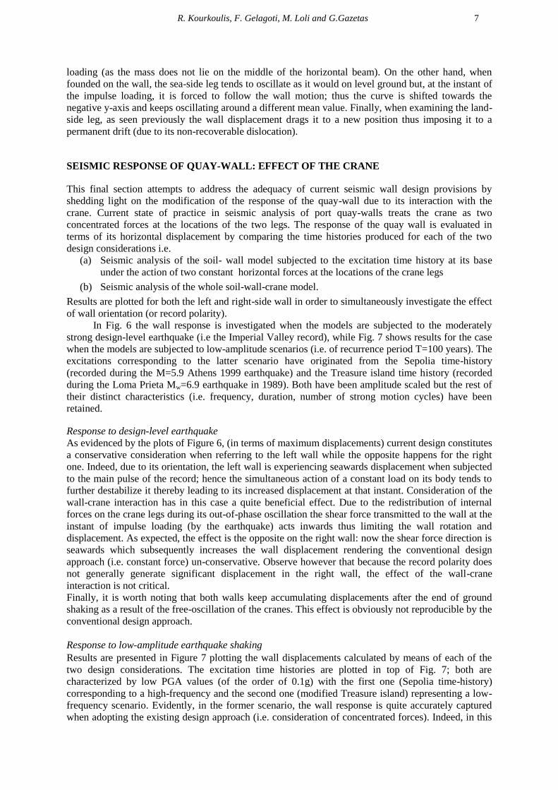
SEISMIC RESPONSE OF QUAY-WALL: EFFECT OF THE CRANE
This final section attempts to address the adequacy of current seismic wall design provisions by
shedding light on the modification of the response of the quay-wall due to its interaction with the
crane. Current state of practice in seismic analysis of port quay-walls treats the crane as two
concentrated forces at the locations of the two legs. The response of the quay wall is evaluated in
terms of its horizontal displacement by comparing the time histories produced for each of the two
design considerations i.e.
(a) Seismic analysis of the soil- wall model subjected to the excitation time history at its base
under the action of two constant horizontal forces at the locations of the crane legs
(b) Seismic analysis of the whole soil-wall-crane model.
Results are plotted for both the left and right-side wall in order to simultaneously investigate the effect
of wall orientation (or record polarity).
In Fig. 6 the wall response is investigated when the models are subjected to the moderately
strong design-level earthquake (i.e the Imperial Valley record), while Fig. 7 shows results for the case
when the models are subjected to low-amplitude scenarios (i.e. of recurrence period T=100 years). The
excitations corresponding to the latter scenario have originated from the Sepolia time-history
(recorded during the M=5.9 Athens 1999 earthquake) and the Treasure island time history (recorded
during the Loma Prieta Mw=6.9 earthquake in 1989). Both have been amplitude scaled but the rest of
their distinct characteristics (i.e. frequency, duration, number of strong motion cycles) have been
retained.
Response to design-level earthquake
As evidenced by the plots of Figure 6, (in terms of maximum displacements) current design constitutes
a conservative consideration when referring to the left wall while the opposite happens for the right
one. Indeed, due to its orientation, the left wall is experiencing seawards displacement when subjected
to the main pulse of the record; hence the simultaneous action of a constant load on its body tends to
further destabilize it thereby leading to its increased displacement at that instant. Consideration of the
wall-crane interaction has in this case a quite beneficial effect. Due to the redistribution of internal
forces on the crane legs during its out-of-phase oscillation the shear force transmitted to the wall at the
instant of impulse loading (by the earthquake) acts inwards thus limiting the wall rotation and
displacement. As expected, the effect is the opposite on the right wall: now the shear force direction is
seawards which subsequently increases the wall displacement rendering the conventional design
approach (i.e. constant force) un-conservative. Observe however that because the record polarity does
not generally generate significant displacement in the right wall, the effect of the wall-crane
interaction is not critical.
Finally, it is worth noting that both walls keep accumulating displacements after the end of ground
shaking as a result of the free-oscillation of the cranes. This effect is obviously not reproducible by the
conventional design approach.
Response to low-amplitude earthquake shaking
Results are presented in Figure 7 plotting the wall displacements calculated by means of each of the
two design considerations. The excitation time histories are plotted in top of Fig. 7; both are
characterized by low PGA values (of the order of 0.1g) with the first one (Sepolia time-history)
corresponding to a high-frequency and the second one (modified Treasure island) representing a low-
frequency scenario. Evidently, in the former scenario, the wall response is quite accurately captured
when adopting the existing design approach (i.e. consideration of concentrated forces). Indeed, in this

8
case the oscillation of the crane is definitely out-of-phase with the ground motion and as such
produces no effect on the wall response. The picture is not the same however when referring to the
long-period shaking which is apparently more perceptible by the crane; this, in turn, results in the
latter imposing loading on the wall thus leading to accumulation of displacement with cycles
ultimately reflecting an under-prediction of the actual wall distortion by the conventional design
approach. Although the intensity of shaking is not high and such under-prediction is not critical, it is
worth highlighting the need of a more realistic consideration of the crane effect in seismic design of
port facilities.
Indicatively, Figure 7b portrays the effect of the wall-crane interaction on the actual response of
the crane when subjected to the low-amplitude scenarios. A similar result as previously is extracted: as
long as the shaking is not rich in long-period pulses, the wall will not modify the crane response with
respect to the level ground conditions. Yet, accumulation of wall outward movement (i.e. in the case
of the long-period modified Treasure Island record) would not let the crane unaffected but rather
create a biased drift pattern: the sea-side leg follows the wall movement gradually building up
unilateral drift as reflected on the slight shift on the drift time-history of Fig. 7b.
0
0.05
0.1
0.15
0 5 10 15 20
uwall – uff
[m]
t : s
Right WALL Left WALL
uwall uff
0
0.05
0.1
0.15
0 5 10 15 20t : s
WALL + CRANE
WALL + Const. V
Figure 6. Effect of the Crane on the response of the quay wall. The produced wall-displacement time histories
are calculated using either the fully coupled soil-wall-crane model (dashed blue line) or the conventional design
approach where the crane is replaced by two constant vertical forces.
CONCLUSIONS
A study has been presented on the seismic response of a container terminal including a soil-quay-wall-
crane interacting system. Non-linear dynamic finite element analyses have been performed subjecting
the systems to several earthquake scenarios. It was shown that:
The rocking response of cranes is not always granted. In fact, although the inertial response of the
wall is usually out-of-phase with the crane, the seaward displacement of the former may impose
kinematically-induced loading on the crane legs producing distortion or even derailment.
Such derailment may occur well before uplifting would take place if the crane was founded on a
level ground
Replacing the crane with two constant vertical forces at the locations of its two legs during seismic
analysis of port quay-walls is an acceptably conservative practice in case of operational-level
earthquakes
In case of design-level shaking, depending on the characteristics of ground motion, the crane may
exert an additional seawards loading on the wall due to redistribution of internal shear forces on its

R. Kourkoulis, F. Gelagoti, M. Loli and G.Gazetas 9
sea-side legs. These may further destabilize the wall producing larger deformation than expected
according to the conventional design approach.
Similar effects may be observed in case of long-period ground shaking (even at low amplitude)
which significantly affects the swaying motion of the crane.
-0.15
-0.05
0.05
0 5 10 15 200 5 10 15 20
0.08 g
Treasure Island [mod] Sepolia_Tp100
0.10 g
ΔuWALL [m]
0
0.025
0.05
0.075
0.1
0 10 20 30 40
0
0.025
0.05
0.075
0.1
0 2 4 6 8 10
Wall + CLOAD
Wall + CRANE
t [s]
-0.2
-0.1
0
0.1
0.2
0 2 4 6 8 10
drift [m]
-0.2
-0.1
0
0.1
0.2
0 10 20 30 40t [s]
CRANE at FF
Wall + CRANE
Figure 7. Comparison between the prediction of the conventional design approach and the fully coupled analysis
in terms of wall displacement and crane distortion expressed in terms of drift (horizontal displacement at the top
of the leg minus that at its bottom); in all cases the models are subjected to moderate seismic scenarios (Modified
Sepolia and Treasure Island records) of PGA<0.1g.
ACKNOWLEDGMENT
This research has been co-financed by the European Union (European Social Fund – ESF) and Greek national
funds through the Operational Program "Education and Lifelong Learning" of the National Strategic Reference
Framework (NSRF) - Research Funding Program: Thales. Investing in knowledge society through the European
Social Fund, Project ID "UPGRADE".
REFERENCES
ASCE (2012) “Seismic Design of Pile-Supported Piers and Wharves (Draft)”, Standards Committee on Seismic
Design of Piers and Wharves, American Society of Civil Engineers, Reston, Virginia.
California State Lands Commission, (2010), Title 24, California Code of Regulations, Part 2, Chapter 31F,
otherwise known as the Marine Oil Terminal Engineering and Maintenance Standards (MOTEMS).
CalTrade (2008), "ILWU Calls for May 1 Dock Walkout," www.caltradereport.com, March 14,.
Dakoulas P., Gazetas G., (2008), “Insight to Seismic Earth and Water Pressures Against Caisson Quay Walls”,
Geotechnique, Vol. 58, No. 2, pp 95-113.

10
DOD (2005), “United Facilities Criteria, Design: Piers and Wharves”, Report UFC 4-152-01, U.S. Army Corps
of Engineers, Naval Facilities Engineering Command, and Air Force Civil Engineer Support Agency, U. S.
Department of Defense.
EERI, 1990, “Loma Prieta, California, Earthquake of October 15, 1989,” Earthquake Spectra, Vol. 06,
upplement, Earthquake Engineering Research Institute, Oakland, California
Egan J.A., Hayden R.F., Scheibel. L.L., Otus M., Serventi G.M., (1992), “Seismic repair at Seventh Street
Marine Terminal “, Grouting Soil Improvement and Geosynthetics, Geotechnical Special Publication No.30,
ASCE, p.p 867-878.
Elnashai A.S., Gencturk B., Kwon O., Al-Qadi I.L., Hashash Y., Roesler J.R., Kim S.J., Jeong S., Dukes J.,
Valdivia A., (2010), “The Maule (Chile) Earthquake of February 27, 2010: Concequence Assessment and
Case Studies”, Mid-America Earthquake Center, Report No. 10-04, 2010-12-31.
Iai S., Matsunaga Y., Morita T., Miyata M., Sakurai H., Oishi H., Ogura H., Ando Y., Tanaka Y., Kato M.,
(1994) “Effects of remedial measures against liquefaction at 1993 Kushiro – Oki earthquake”, Proc. Fifth
U.S. – Japan Workshop on Earthquake resistant design of Lifeline Facilities and Countermeasures against
Soil Liquefaction, National Center for Earthquake Engineering Research, NCEER-94-0026, p.p. 135-152.
Koshbab B. (2010) Seismic Performance evaluation of port container cranes allowed to uplift. PhD thesis,
Georgia Institute of Technology, May 2010 p.p.326
PIANC (2002) Seismic Design Guidelines for Port Structures, World Association for Waterborne Transport
Infrastructure, Brussels, Belgium.
Pitilakis K. and Moutsakis A., (1989), “Seismic analysis and behaviour of gravity retaining walls – the case of
Kalamata harbour quaywall”, Soil and Foundations, Vol. 29, No. 1, pp. 1-17.
Port of Los Angeles (2004) Code for Seismic Design, Upgrade and Repair of Container Wharves, San Pedro,
California.
Soderberg E., J. Hsieh, and A. Dix (2009) "Seismic Guidelines for Container Cranes," in TCLEE 2009.
Oakland, CA: ASCE
Sugano T., and Iai S., (1999), “Damage to port facilities”, The 1999 Kocaeli Earthquake Turkey – Investigation
into Damage to Civil Engineering Structures, Earthquake Engineering Committee, Japan Society of Civil
Engineers, p.p.6-1 – 6-14.
Sugano, T., Takenbo, M., Suzuki, T., and Shiozaki, Y., (2008). Design procedures of seismicisolated container
crane at port, in Proc. of 14th World Conference on Earthquake Engineering. Beijing, China, October 2008.
Werner, S.D. (1998) Seismic Guidelines for Ports, Technical Council on Lifeline Engineering, Monograph