Internet Protocol (IP) v4
76
Internet Protocol (IP) Internet Protocol (IP) v4 v4 IP version 4 Defined in RFC 791 Two parts Specification of interface with a higher layer (TCP) Specification of actual protocol format and mechanisms Will (eventually) be replaced by IPv6
Transcript of Internet Protocol (IP) v4

Internet Protocol (IP)Internet Protocol (IP) v4v4
IP version 4
Defined in RFC 791
Two partsSpecification of interface with a higher layer (TCP)
Specification of actual protocol format and mechanisms
Will (eventually) be replaced by IPv6

IPv4IPv4라우팅기능수행
데이터그램(Datagram)방식각데이터그램은독립적으로처리
각데이터그램은서로다른경로로전달될수있음
각데이터그램은순서가바뀌어전달될수있음
상위계층의세그먼트를네트워크가요구하는크기의패킷으로분할하여전송
신뢰성없는비연결형데이터그램프로토콜
Best effort service
오류검사및추적기능을수행하지않음
패킷폐기시 “ICMP 메시지”를최초발신호스트에게전송

IP ServicesIP ServicesPrimitives
Functions to be performed
Form of primitive implementation dependent
e.g. subroutine call
ParametersUsed to pass data and control info
IP ParametersIP ParametersSource & destination addressesProtocol
Recipient e.g. TCPType of service
Specify treatment of data unit during transmissionIdentification
Source, destination address and user protocolUniquely identifies PDUNeeded for re-assembly and error reporting
Don’t fragment indicatorCan IP fragment dataIf not, may not be possible to deliver
Time to liveData lengthOption dataUser data

Type of Service
Precedence8 levels
ReliabilityNormal or high
DelayNormal or low
ThroughputNormal or high

IP OptionsIP OptionsSecurity데이터그램에보안 tag 부착
Source routing경유할라우터들의주소목록을지정
Strictly or loosely
Route recording경유라우터주소와시간을기록
Stream identification예약자원들의이름지정
Timestamping경유라우터의통과시간을기록

IPIPv4 Headerv4 Header

Header Fields (1)Header Fields (1)Version
Currently 4IP v6 - see later
Internet header lengthIn 32 bit words (including options)
DS/ECN (was type of service)Differential Service/Explicit Congestion Notification
Total lengthOf datagram, in octets
IdentificationSequence numberIdentify datagram uniquely with addresses/protocol
FlagsMore bitDon’t fragment
Fragmentation offset
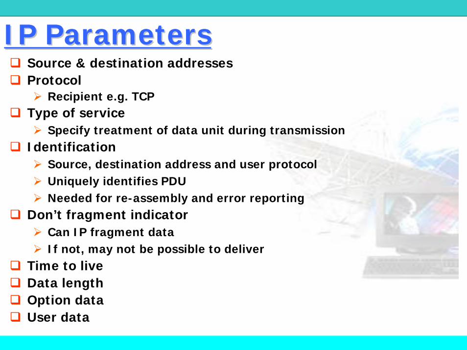
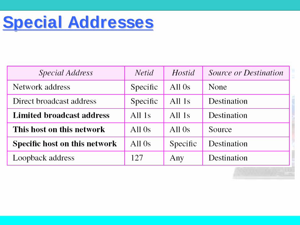
Header Fields (2)Header Fields (2)Time to liveProtocol
Next higher layer to receive data field at destinationHeader checksum
Reverified and recomputed at each router16 bit 1’s complement sum of all 16 bit words in headerSet to zero during calculation
Source address/Destination addressOptionsPadding
To fill to multiple of 32 bits longData
Carries user data from next layer upInteger multiple of 8 bits long (octet)Max length of datagram (header plus data) is 65,535 octets

Q: offset = 100, HLEN = 5, total length field = 100 일 경우 , 첫바이트와마지막바이트의번호는?
A:처음바이트의번호는 100 × 8 = 800total length = 100header length = 2080 bytes in this datagram 마지막바이트의번호는 879
ExampleExample

Q: IP 패킷이45000028000100000102.....(16)
일경우, 몇개의홉을지나갈수있는가? 또한상위계층프로토콜은?
A: time-to-live field = 01 (하나의홉)
protocol field = 02 (IGMP)
ExampleExample

IP AddressIP Address
Internet addressIP 계층에서사용되는식별자32 bit 2진주소The address space of IPv4 is 232 or 4,294,967,296.
netid와 hostid로구분인터넷에서호스트와라우터를유일하게구분

IPv4 Address FormatsIPv4 Address Formats

Addresses Per ClassAddresses Per Class

Dotted Decimal NotationDotted Decimal Notation보다편리하고읽기쉽게하기위해사용

Example : Class C AddressExample : Class C Address

Internet ExampleInternet Example
220.3.6.0(클래스 C)는토큰링200.78.6.0은교환망134.18.0.0(클래스 B)는이더넷207.42.56.0(클래스 C)는점-대-점WAN124.0.0.0(클래스 A)는이더넷
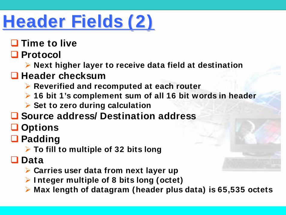
Special AddressesSpecial Addresses

Direct Broadcast AddressDirect Broadcast AddressHostid필드가모두 “1”인주소
라우터가특정네트워크의모든호스트에패킷을보낼때사용
목적지주소로만사용

Limited Broadcast AddressLimited Broadcast Address현재네트워크레벨의브로드캐스트주소
호스트가현재네트워크내의모든호스트에게메시지전달
다른네트워크로가는것을라우터가제한함
클래스 E 주소

This NetworkThis NetworkNetid필드가모두 “0”인주소같은네트워크에있는다른호스트에게메시지보낼때사용 (라우터에서차단)

Loopback AddressLoopback Address첫번째바이트가 “127”인 IP 주소소프트웨어시험용
클라이언트프로세스가동일한시스템상에있는서버프로세스에게메시지전송시사용
목적지주소로만사용

Classless AddressingClassless AddressingVariableVariable--length blocks are assigned that belong to length blocks are assigned that belong to
no class. no class.
In this architecture, the entire address space (2In this architecture, the entire address space (23232
addresses) is divided into blocks of different sizes.addresses) is divided into blocks of different sizes.
Classless Interdomain Routing (CIDR)
Classful addressing is a special case of classless
addressing. n = 8 (class A), 16 (class B), or 24 (class C)

Prefix LengthPrefix LengthPrefix : Prefix : netidnetid
Suffix : Suffix : hostidhostid
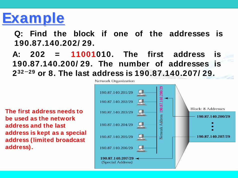
Q: Find the block if one of the addresses is 190.87.140.202/29.A: 202 = 11001010. The first address is 190.87.140.200/29. The number of addresses is 232−29 or 8. The last address is 190.87.140.207/29.
The first address needs to be used as the network address and the last address is kept as a special address (limited broadcast address).
ExampleExample

SubnettingSubnettingAllows arbitrary complexity of internetworked LANs within organization
Each LAN assigned subnet number
Site looks to rest of internet like single network
Local routers route within subnettednetwork

22--Layer Hierarchical StructureLayer Hierarchical StructureClassful addressing : netid + hostid먼저 netid를사용하여네트워크에도달한후에 hostid를사용하여호스트에도달
A, B, C 클래스는 2단계계층구조

3단계이상의계층구조를위하여서브넷팅활용
33--Layer Hierarchical StructureLayer Hierarchical Structure

33--Layer Hierarchical StructureLayer Hierarchical Structure

MaskingMaskingIP 주소중에서네트워크주소를추출하기위해마스크이용
Subnet mask indicates which bits are subnet number and which are host number
마스크 : 1- netid, 0 - hostid

Default MasksDefault Masks
The network address is the beginning address of each block. It can be found by applying the default mask to any of the addresses in the block (including itself). It retains the netid of the block and sets the hostid to zero.

Subnet and MaskSubnet and Mask

Subnet Mask CalculationSubnet Mask Calculation
Binary Representation Dotted Decimal
IP address 11000000.11100100.00010001 .00111001 192.228.17.57
Subnet mask 11111111.11111111.11111111 .11100000 255.255.255.224
Bitwise AND ofaddress and mask(resultantnetwork/subnetnumber)
11000000.11100100.00010001 .00100000 192.228.17.32
Subnet number 11000000.11100100.00010001 .001 1
Host number 00000000.00000000.00000000 .00011001 25

Routing Using SubnetsRouting Using Subnets

ExampleExampleB 클래스주소를가진기관이 12개의서브넷이필요할때
12개지만 14개필요(subnetid필드가모두 1인것과 0인것)
서브넷할당을위한최소비트수 : 4개
나머지 12개비트는 hostid (212 = 4,096) 지정, 실제는4,094 개
Mask = 255.255.240.0 (240 = 11110000)
서브넷
X.Y.0000hhhh.hhhhhhhh (X.Y.0.0) ~
X.Y.1111hhhh.hhhhhhhh (X.Y.240.0)


A company has three offices: Central, East, and West. The Central office is connected to the East and West offices via private, point-to-point WAN lines. The company is granted a block of 64 addresses with the beginning address 70.12.100.128/26. The management has decided to allocate 32 addresses for the Central office and divides the rest of addresses between the two offices.
CentralWest East
64 addresses70.12.100.128/26
R R R R
R
ExampleExample

The company will have three subnets, one at Central, one at East, and one at West.
a. The Central office uses the network address 70.12.100.128/27 (70.12.100.10000000/27). The addresses in this subnet are 70.12.100.128/27 to 70.12.100.159/27. (32 addresses) Note that three of these addresses are used for the routers and the company has reserved the last address in the sub-block. Note that the interface of the router that connects the Central subnet to the WAN needs no address because it is a point-to-point connection.

b. The West office uses the network address 70.12.100.160/28 (70.12.100.10100000/28). The addresses in this subnet are 70.12.100.160/28 to 70.12.100.175/28. (16 addresses) Note that one of these addresses is used for the router and the company has reserved the last address in the sub-block.
c. The East office uses the network address 70.12.100.176/28. (70.12.100.10110000/28) The addresses in this subnet are 70.12.100.176/28 to 70.12.100.191/28. (16 addresses) Note that one of these addresses is used for the router and the company has reserved the last address in the sub-block.


An ISP is granted a block of addresses starting with 190.100.0.0/16 (65,536 addresses). The ISP needs to distribute these addresses to three groups of customers as follows:
a. The first group has 64 customers; each needs 256 addresses.b. The second group has 128 customers; each needs 128 addressesc. The third group has 128 customers; each needs 64 addresses.
Design the subblocks and find out how many addresses are still available after these allocations.
ExampleExample

Group 1: 64개의 서브넷, 서브넷당 256개의 주소 필요 (8 비트의suffix와 24비트의 prefix)
01 : 190.100.0.0/24 ~ 190.100.0.255/2402 : 190.100.1.0/24 ~ 190.100.1.255/24
…………………………………..64 : 190.100.63.0/24 ~ 190.100.63.255/24Total = 64 × 256 = 16,384
Group 2: 128개의 서브넷, 서브넷당 128개의 주소 필요 (7비트의suffix와 25비트의 prefix)
001 : 190.100.64.0/25 ~ 190.100.64.127/25002 : 190.100.64.128/25 ~ 190.100.64.255/25
…………………………………..128 : 190.100.127.128/25 ~ 190.100.127.255/25Total = 128 × 128 = 16,384

Group 3: 128개의서브넷, 서브넷당 64개의주소필요 (6비트의 suffix, 26비트의 prefix)
001 : 190.100.128.0/26 ~ 190.100.128.63/26
002 : 190.100.128.64/26 ~ 190.100.128.127/26
…………………………
128 : 190.100.159.192/26 ~ 190.100.159.255/26
Total = 128 × 64 = 8,192
Number of granted addresses: 65,536
Number of allocated addresses: 40,960
Number of available addresses: 24,576


ChecksumChecksum
보통 n=16
1.1. 패킷을패킷을 N N 비트비트 짜리짜리 섹션으로섹션으로 분할분할
2.2. 모든모든 섹션을섹션을 11의의 보수보수 연산으로연산으로 더한다더한다
3.3. 결과의결과의 보수를보수를 취하여취하여 체크섬으로체크섬으로 함함

Record Route OptionRecord Route Option데이터그램을처리한라우터의주소기록
최대 9개의 IP 주소기록가능 (출구 IP 주소기록)
포인터: 첫번째빈공간을가르킴

Record Route OptionRecord Route Option

Strict Source RouteStrict Source Route OptionOption데이터그램이거쳐야할경로를미리지정하기위해사용
데이터그램은옵션에정의된모든라우터방문

Strict Source RouteStrict Source Route OptionOption

Loose Source Route OptionLoose Source Route Option
Strict source route 옵션과비슷하지만리스트에없는라우터도방문가능

Timestamp OptionTimestamp Option라우터가데이터그램을처리하는시간기록 (ms단위)
Overflow: 필드가없어서시간을기록하지못한라우터의수
Flag: 방문한라우터의의무표시

Timestamp OptionTimestamp Option

Timestamp ExampleTimestamp ExampleCode=68, 길이=28바이트, 포인터=5, Flag=1

Router ArchitectureRouter Architecture

Input /Output Port

IP StructureIP Structure

헤더추가모듈: encapsulationPDU처리모듈큐: 입출력큐라우팅테이블: 패킷의다음홉주소결정하기위해사용라우팅모듈MTU 테이블: 단편화모듈이특정인터페이스의MTU를찾기위해사용단편화모듈재조립모듈
IP StructureIP Structure

Routing ModuleRouting Module
IP 패킷수신라우팅테이블을참조하여최적경로를찾는다
다음홉주소와함께단편화모듈로보내진다

Forwarding in Classful Addressing
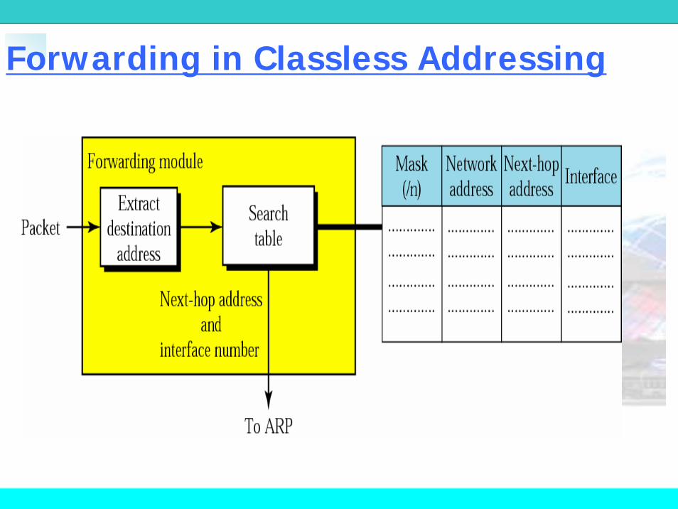
Forwarding in Classless Addressing

Mask DA Next Hop I/F255.255.0.0 134.18.0.0 -- m0
255.255.0.0 129.8.0.0 222.13.16.40 m1
255.255.255.0 220.3.6.0 222.13.16.40 m1
0.0.0.0 0.0.0.0 134.18.5.2 m0
Routing TableRouting Table

Show the routing tables for router R1.
ExampleExample

Router R1 receives a packet with destination address 192.16.7.14. Show how the packet is forwarded.
Solution
• The destination network is class C.
• The network address is extracted by masking off the leftmost 24 bits of the destination address; the result is 192.16.7.0.
• The table for Class C is searched. The next-hop address 111.15.17.32. and the interface m0 are passed to ARP.
ExampleExample

Make a routing table for router R1
ExampleExample

Can we find the configuration of a router, if we know only its routing table?
Solution
three interfaces: m0, m1, and m2.
three networks (110.70.0.0, 180.14.0.0, 190.17.0.0) directly connected to router R1.
two networks (140.6.12.64/26, 130.4.8.0/24) indirectly connected to R1.
ExampleExample


HeaderHeader--Adding ModuleAdding ModuleReceive: data, destination address
1. Encapsulate the data in an IP datagram.
2. Calculate the checksum and insert it in the checksum field.
3. Send the data to the corresponding input queue.
4. Return.

1. Remove one datagram from one of input queues.2. If (destination address is 127.X.Y.Z or matches one of the local addresses)
1. Send the datagram to the reassembly module.2. Return.
3. If (machine is a router)1. Decrement TTL.
4. If (TTL =< 0)1. Discard the datagram.2. Send an ICMP error message.3. Return.
5. Send the datagram to the routing module.6. Return.
Processing ModuleProcessing Module

IP FragmentationIP Fragmentation

IP FragmentationIP FragmentationUses fields in header
Data unit identifier (ID)Identifies end system originated datagram동일한세그먼트에서분할된단편들은같은식별자값을가짐
Data lengthLength of user data in octets
OffsetPosition of fragment of user data in original datagramIn multiples of 64 bits (8 octets)
More flagIndicates that this is not the last fragment

Fragmentation ExampleFragmentation Example

Fragmentation ExampleFragmentation Example

Fragmentation ModuleFragmentation ModuleReceive: an IP packet from routing module1. Extract the size of the datagram.2. If (size > MTU of the corresponding network)
1. If (“D” (do not fragment) bit is set)1. Discard the datagram.2. Send an ICMP error message3. Return.
2. Else1. Calculate the maximum size.2. Divide the datagram into fragments.3. Add header to each fragment.4. Add required options to each fragment.5. Send the datagrams.6. Return.
3. Else 1. Send the datagram.
4. Return.

ReassemblyReassembly같은 ID를가진단편들이도착하면, 버퍼의적절한위치에삽입한다. 재조립은오프셋 0인단편부터More 플래그값이 0인단편까지모두모여야완성된다.Reassembly table 상태(state) : FREE 또는 IN-USE
IP 주소 : 발신지주소
데이터그램 ID : 단편을구분하는번호
타임아웃 : 단편이도착해야하는시간
단편 : 연결리스트의포인터

Reassembly FailureReassembly Failure
Re-assembly may fail if some fragments get lost
Re-assembly time outAssigned to first fragment to arrive
If timeout expires before all fragments arrive, discard partial data
Use packet lifetime (time to live in IP)If time to live runs out, kill partial data

Receive: an IP datagram from the processing module1. If (offset value is zero and the M bit is 0)
1. Send the datagram to the appropriate queue.2. Return.
2. Search the reassembly table for the corresponding entry.3. If (not found)
1. Create a new entry.4. Insert the fragment at the appropriate place in the link list
1. If(all fragments have arrived)1. Reassemble the fragments2. Deliver the datagram to the corresponding upper layer protocol3. Return
2. Else1. Check the time-out2. If(time-out expired)
1. Discard all fragments2. Send an ICMP error message
5. Return
Reassembly Module Reassembly Module