Internet access and backbone technology - cs.columbia.eduhgs/teaching/ais/slides/2015 AIS... ·...
16
Internet access and backbone technology 1 Henning Schulzrinne Columbia University COMS 6181 – Spring 2015 03/09/2015 3/09/15 AIS 2015
-
Upload
vuongkhanh -
Category
Documents
-
view
215 -
download
0
Transcript of Internet access and backbone technology - cs.columbia.eduhgs/teaching/ais/slides/2015 AIS... ·...
Internet access and backbone technology
1
Henning Schulzrinne Columbia University COMS 6181 – Spring 2015 03/09/2015
3/09/15 AIS 2015
Key objectives • Fundamental models for communication • How are bits switched? • How does a large router work internally? • What are the limits to communication capacity? • How do DSL and cable modems work?
3/09/15 AIS 2015 2

Overview • Physical layer for CS majors
• modulation • spectral efficiency
• Residential last-mile technologies • DSL • Cable (DOCSIS) • Residential fiber
• Backbone networks • Wireless networks
3 3/09/15 AIS 2015

Circuits, VCs and packets
4
Circuits virtual circuits packets Resources copper circuit (space)
time switching capacity (maybe)
none (except with resource reservation)
Information unit
bit, byte cell, frame packet
Routing switched (e.g., timeslot 15 to timeslot 13)
VC identifier (switch-local)
IP address (network-global)
Examples phone, ISDN, X.21 ATM, MPLS IP, Ethernet
3/09/15 AIS 2015

N
1 2
1
N
2
N –1
…
…
Circuit switching: crossbar space switch l N x N array of
crosspoints l Connect an input to
an output by closing a crosspoint
l Non-blocking: Any input can connect to idle output
l Complexity: N2
crosspoints
3/09/15 AIS 2015 5

l l l
n×k
n×k
n×k
n×k
N/n × N/n
N/n × N/n
N/n × N/n
k×n 1
2
N/n
N inputs
1
2
3 3
N/n
N outputs
1
2
k
2(N/n)nk + k (N/n)2 crosspoints
k×n
k×n
k×n
…
…
…
CS: multistage space switch • Large switch built from multiple stages of small switches • n inputs to a first-stage switch share k paths through intermediate crossbar
switches • Larger k (more intermediate switches) means more paths to output • In 1950s, Clos asked, “How many intermediate switches required to make
switch non-blocking?
3/09/15 AIS 2015 6
N/n first stage, each with n inputs, k outputs
k intermediate

nxk
nxk
nxk
N/n x N/n
N/n x N/n
N/n x N/n
kxn 1
N/n
Desired input
1
j m
N/n
Desired output
1
2n-1
kxn
kxn
n-1
N/n x N/n n+1
N/n x N/n 2n-2
Free path Free path
n-1 busy
n-1 busy
…
…
…
…
CS: Clos Non-Blocking Condition: k=2n-1 l Request connection from last input to input switch j to last output in output switch m
l Worst Case: All other inputs have seized top n-1 middle switches AND all other outputs have seized next n-1 middle switches
l If k=2n-1, there is another path left to connect desired input to desired output
# internal links = 2x # external links
3/09/15 AIS 2015 7

The Internet Protocol Journal8
Figure 4: Logical Structure of a Line Interface Card
PacketManager
DRAM
Back
plan
eCPU
Packet Buffer FIB Lookup Bank
Network PHY
Media
TCAM *DRAM
The result of the forwarding-table lookup is the hardware address of the outgoing interface. If this interface is located on the same line card, then the packet is queued to the output structure associated with that local interface. If the interface is located on another card, then the packet is passed to the packet manager for transmission along the backplane to the switching unit to be passed to the outbound line interface card.
A critical aspect of the design of the line interface card is the memory structure used to support the network-level destination-address lookup. This lookup must be completed within the time defined by the maximal packet arrival rate, so for high-speed line cards the performance of this forwarding-table memory structure is critical.
An approach used in some routers is to use Ternary Content Addressable Memory (TCAM). TCAMs store a routing prefix in each memory “slot,” using a ternary-state representation of the bits within the prefix (“ternary” because the stored values in the table are either “1,” “0,” or “don’t care”). When presented with an IP address, the TCAM module returns the address of the router interface slot that is the longest match network prefix against the destination address. The advantage of TCAM is that it is consistent, in that every lookup takes just one TCAM cycle time. However, TCAM memory requires a significantly higher gate count per stored bit (up to 24 gates per bit), and the storage structure can be somewhat inefficient, so although TCAM offers consistent performance, it is expensive and consumes a significant level of power on the line card. TCAM is an expensive approach.
What’s So Special About 512? continued
Backbone router
3/09/15 AIS 2015 8
The Internet Protocol Journal8
Figure 4: Logical Structure of a Line Interface Card
PacketManager
DRAM
Back
plan
e
CPU
Packet Buffer FIB Lookup Bank
Network PHY
Media
TCAM *DRAM
The result of the forwarding-table lookup is the hardware address of the outgoing interface. If this interface is located on the same line card, then the packet is queued to the output structure associated with that local interface. If the interface is located on another card, then the packet is passed to the packet manager for transmission along the backplane to the switching unit to be passed to the outbound line interface card.
A critical aspect of the design of the line interface card is the memory structure used to support the network-level destination-address lookup. This lookup must be completed within the time defined by the maximal packet arrival rate, so for high-speed line cards the performance of this forwarding-table memory structure is critical.
An approach used in some routers is to use Ternary Content Addressable Memory (TCAM). TCAMs store a routing prefix in each memory “slot,” using a ternary-state representation of the bits within the prefix (“ternary” because the stored values in the table are either “1,” “0,” or “don’t care”). When presented with an IP address, the TCAM module returns the address of the router interface slot that is the longest match network prefix against the destination address. The advantage of TCAM is that it is consistent, in that every lookup takes just one TCAM cycle time. However, TCAM memory requires a significantly higher gate count per stored bit (up to 24 gates per bit), and the storage structure can be somewhat inefficient, so although TCAM offers consistent performance, it is expensive and consumes a significant level of power on the line card. TCAM is an expensive approach.
What’s So Special About 512? continued
Route processor
cross-connect (“backplane”)
may have buffers
TCAM = ternary content addressable memory

Example: Cisco CRS-1
3/09/15 AIS 2015 9

Physical media: capacity • Capacity has theoretical limit
• Shannon’s Law: capacity limit given by • C = B log2 (1 + S/N) with spectral bandwidth B • E.g., phone has B = 3000 Hz, S/N = 35 dB, C = 34.8 kb/s
• dB = • E.g., 25 dB =
• Speed has physical limits: c in free space, 0.66 c in fiber
10 3/09/15 AIS 2015
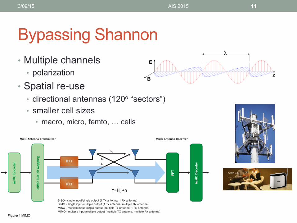
Bypassing Shannon • Multiple channels
• polarization
• Spatial re-use • directional antennas (120o “sectors”) • smaller cell sizes
• macro, micro, femto, … cells
11 3/09/15 AIS 2015
7
LTE Resource Guide
Figure 4 MIMO
Multiple Input Multiple Output (MIMO)
Most modern wireless communication techniques use MIMO to increase the data rate to a user as well as to provide better coverage at the cell edge. Various techniques are available, including transmission of separate data streams from each antenna (spatial multiplexing), transmission of identical streams of data from each antenna (transmit diversity), reception on multiple antennas (receive diversity), and various combinations thereof. These techniques can be generalized as Single Input Single Output (SISO), Single Input Multiple Output (SIMO), Multiple Input Single Output (MISO), and Multiple Input Multiple Output (MIMO) as shown in figure 4.
For LTE Rel. 8, downlink MIMO configurations from SISO to 2x2 and 4x4 MIMO are supported, and the MIMO configuration changes dynamically based on measurement reports from the wireless device. For LTE Advanced, MIMO configurations up to 8x8 in the downlink and 4x4 in the uplink are supported in combination with Carrier Aggregation (CA), which uses multiple carriers.
For LTE Rel. 8, when a user is close to a base station and propagation conditions are optimal, 2x2 MIMO may be used with a high data rate to the wireless device. When a user is at a cell edge, one or both of the diversity modes may be used to increase the Signal to Interference plus Noise Ratio (SINR).
SISO - single input/single output (1 Tx antenna, 1 Rx antenna)SIMO - single input/multiple output (1 Tx antenna, multiple Rx antenna)MISO - multiple input, single output (multiple Tx antenna, 1 Rx antenna)MIMO - multiple input/multiple output (multiple TX antenna, multiple Rx antenna)

Multiplexing • Time
• TDxxx • typically, “time slots”
• Frequency • one signal à one frequency • multiple frequencies à OFDM
• e.g., DSL, LTE, 802.11a/n, …
• Phase (time-shift)
12 3/09/15 AIS 2015
6
LTE Resource Guide
OFDMA
The downlink LTE air interface is based on Orthogonal Frequency Domain Multiplexing Access (OFDMA), a multi-carrier scheme that allocates radio resources to multiple users based on frequency (subcarriers) and time (sym-bols) using Orthogonal Frequency Division Multiplexing (OFDM). For LTE, OFDM subcarriers are typically spaced at 15 kHz and modulated with QPSK, 16-QAM, or 64-QAM modulation. OFDMA allows a network to flexibly assign bandwidth to a user based on bandwidth needs and the user’s data plan. Unassigned subcarriers are switched off, thus reducing power consumption and interference. OFDMA uses OFDM; however, it is the scheduling and assignment of radio resources that makes OFDMA distinctive. The OFDM diagram in Figure 2 shows a scenario where the subcar-riers assigned to a set of users are static for a period of time. In the OFDMA diagram, multiple users flexibly share the subcarriers, with differing bandwidth available to different users at different times.
SC-FDMA
In the uplink, LTE uses a pre-coded version of OFDM called Single Carrier Frequency Domain Multiple Access (SC-FDMA). SC-FDMA is used in place of OFDMA due to several factors, including the high current requirements for OFDMA-based power amplifiers and correspondingly short battery life. Lower Peak-to-Average Power Ratio for SC-FDMA-based power amplifiers results in extended battery life along with improved uplink performance.
In SC-FDMA, data is spread across multiple subcarriers.
This differs from OFDMA, where each subcarrier trans-ports unique data. The need for a complex receiver makes SC- FDMA unacceptable for the downlink due to size and processing power limitations in a wireless device.
Figure 3 In OFDM, each frequency component carriesunique information. In SC-FDMA, the information isspread across multiple subcarriers.
Figure 2 OFDM vs. OFDMA. Each color represents a burst of user data. In a given period, OFDMA allows users to share the available bandwidth.
T1 circuit (1.54 Mb/s – 24 voice ch.)
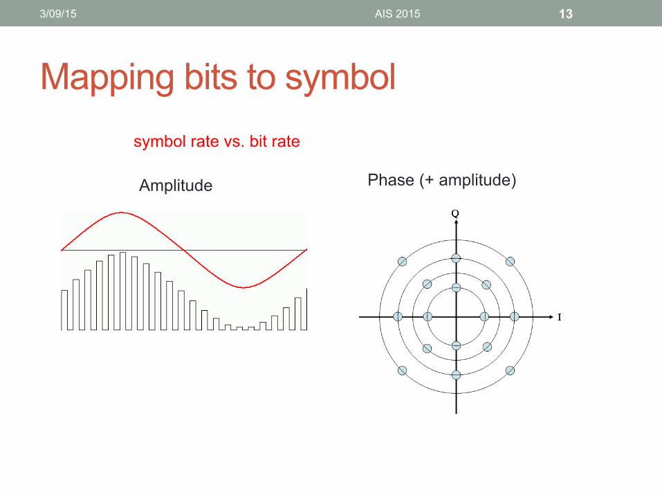
Mapping bits to symbol
13
Phase (+ amplitude)
symbol rate vs. bit rate
Amplitude
3/09/15 AIS 2015

Spectral efficiency
14
Medium Spectrum Data rate b/Hz Modem (V.92) 3,100 Hz 56 kb/s 18.1 2G cellular (GSM) 0.2 MHz 0.52 LTE 20 MHz 326 Mb/s <16.3 ADSL downlink 0.962 12 Mb/s 12.5 WiFi 802.11 a/g 20 MHz < 54 Mb/s < 2.7 WiFi 802.11 n 20 MHz < 144 Mb/s < 7.2
3/09/15 AIS 2015
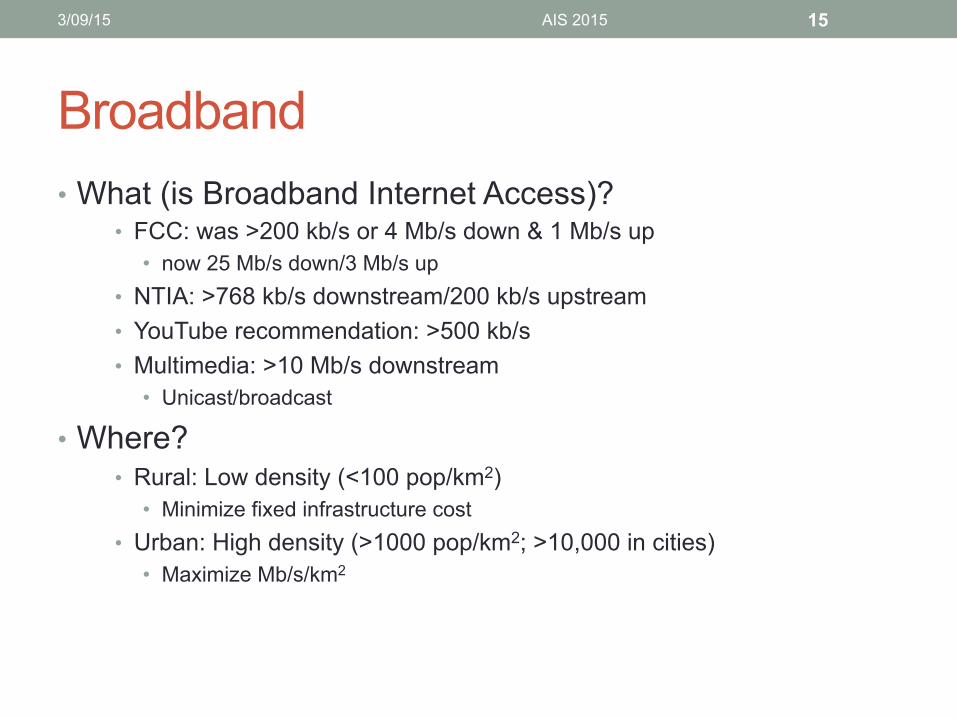
Broadband • What (is Broadband Internet Access)?
• FCC: was >200 kb/s or 4 Mb/s down & 1 Mb/s up • now 25 Mb/s down/3 Mb/s up
• NTIA: >768 kb/s downstream/200 kb/s upstream • YouTube recommendation: >500 kb/s • Multimedia: >10 Mb/s downstream
• Unicast/broadcast
• Where? • Rural: Low density (<100 pop/km2)
• Minimize fixed infrastructure cost • Urban: High density (>1000 pop/km2; >10,000 in cities)
• Maximize Mb/s/km2
3/09/15 AIS 2015 15

Cost for providing access cost
distance
possibly another step
when crossing oceans
within home
within campus/AS (multiple L2s)
same L2 switch (non-blocking)
across provider boundaries
3/09/15 AIS 2015 16