International Standard 5343
9
International Standard 5343 INTERNATIONAL ORGANIZATION FOR STANDARDlZATION*MEWYHA~~HAR OPïAHH3AUHR no CTAHLIAPTH3AUHW«)RGANlSATlON INTERNATIONALE DE NORMACISATION ! Criteria for evaluating flexible rotor balance Critères d'équilibrage pour les rotors flexibles First edition - 1983-10-01 UDC 02-253:62-756 Ref. No. iSO5343-1983(E) Descriptors : balancing, rotors, definitions, tests, generalities, measurement, vibration, balancing equipment, classification. Price based on 9 pages iTeh STANDARD PREVIEW (standards.iteh.ai) ISO 5343:1983 https://standards.iteh.ai/catalog/standards/sist/e234ea11-d6f0-42cc-94fb- 19501e2d0ba6/iso-5343-1983
Transcript of International Standard 5343
International Standard 5343 INTERNATIONAL ORGANIZATION FOR STANDARDlZATION*MEWYHA~~HAR OPïAHH3AUHR no CTAHLIAPTH3AUHW«)RGANlSATlON INTERNATIONALE DE NORMACISATION !
Criteria for evaluating flexible rotor balance Critères d'équilibrage pour les rotors flexibles
First edition - 1983-10-01
UDC 02-253:62-756 Ref. No. iSO5343-1983(E) Descriptors : balancing, rotors, definitions, tests, generalities, measurement, vibration, balancing equipment, classification.
Price based on 9 pages
iTeh STANDARD PREVIEW(standards.iteh.ai)
ISO 5343:1983https://standards.iteh.ai/catalog/standards/sist/e234ea11-d6f0-42cc-94fb-
19501e2d0ba6/iso-5343-1983
Foreword IS0 (the International Organization for Standardization) is a worldwide federation of national standards bodies (IS0 member bodies). The work of developing International Standards is carried out through IS0 technical committees. Every member body interested in a subject for which a technical committee has been authorized has the right to be represented on that committee. International organizations, governmental and non-governmental, in liaison with ISO, also take pari in the work.
Draft International Standards adopted by the technical committees are circulated to the member bodies for approval before their acceptance as International Standards by the IS0 Council.
International Standard IS0 !j343 was developed by Technical Committee ISO/TC 108, Mechanical vibration and shock, and was circulated to the member bodies in June 1982.
I It has been approved by the member bodies of the following countries :
Austria Belgium Canada China Czechoslovakia Egypt, Arab Rep. of
Germany, F.R. Romania Italy South Africa, Rep. of Japan United Kingdom Korea, Rep. of USA Netherlands New Zealand
The member body of the following country expressed disapproval of the document on technical grounds :
France I
iTeh STANDARD PREVIEW(standards.iteh.ai)
ISO 5343:1983https://standards.iteh.ai/catalog/standards/sist/e234ea11-d6f0-42cc-94fb-
19501e2d0ba6/iso-5343-1983
~ ~~
INTERNATIONAL STANDARD IS0 5343-1983 (E)
Criteria for evaluating flexible
O Introduction
The aim of balancing any rotor is satisfactory running when installed on site. In this context "satisfactory running" means that no more than an acceptable level of vibration is transmitted to the machine by the unbalance remaining in the rotor. In the case of a flexible rotor, it also means that no more than an ac- ceptable magnitude of deflection occurs in the rotor at any speed up to maximum service speed.
Most rotors are balanced by their manufacturers prior to machine assembly because afterwards, inter alia, there may be only limited access to the rotor. Furthermore, completion and balancing of the rotor is often the stage at which a rotor is ap- proved by the purchaser. Thus, while satisfactory running on site is the aim, the balance quality of the rotor is usually initially assessed in a balancing facility. Satisfactory running on site is usually judged in relation to vibration from all causes, while in the balancing facility primarily once-per-revolution effects are considered.
This International Standard shows how criteria for use in the balancing facility may be derived from either vibration limits specified for the assembled and installed machine or unbalance limits specified for the rotor. If such limits are not available, this International Standard shows how they may be derived from IS0 2372, or IS0 394511SO 2373 (if desired in terms of vibra- tion) or from IS0 1940 (if desired in terms of permissible residual unbalance). IS0 1940 is concerned with the balance quality of rotating rigid bodies and is thus not directly ap- plicable to flexible rotors because they may undergo significant bending deflection. However, in clause 6 of this International Standard, methods are presented for adapting the criteria of IS0 1940 to flexible rotors.
This International Standard on criteria is to be read in conjunc- tion with IS0 5406.
The criteria values given in annex A are derived from IS0 2372, and those in 6.2 and 6.3 are based on the results of practical experience. It is recommended that users compare these values with their own experiences. If discrepancies or omissions are discovered, comments on the results of such comparisons will be welcome. 1)
The methods and criteria values given are the result of experience with general industrial machinery. They may not be directly applicable to specialized equipment or to special cir- cumstances. Information on such exceptions will also be welcome. 1 )
rotor balance
1 Scope and field of application
This International Standard specifies two methods for evaluating the quality of balance of a flexible rotor in a balanc- ing facility before machine assembly, with the aim that the rotor will run satisfactorily after machine assembly and installa- tion on site. If the rotor balance tolerances suggested herein are achieved during correction in a balancing facility, the final vibration limits of the assembled machine (see IS0 2372 and IS0 3945) will most probably be achieved. Accordingly, the criteria specified are those to be met when the rotor is tested in the balancing facility, but they are derived from those specified for the complete machine, when installed, or from values known to ensure satisfactory running of the rotor when it is installed.
2 References
IS0 1925, Balancing - Vocabulary,
IS0 1940, Balance quality of rotating rigid bodies.
IS0 2041, Vibration and shock - Vocabulary.
IS0 2372, Mechanical vibration of machines with operating speeds from 10 revls to 200 revfs - Basis for specifying evaluation standards.
I SO 2373, Mechanical vibration of certain rotating electrical machinery with shaft heights between 80 mm and 400 mm - Measurement and evaluation of the vibration severity.
IS0 3945, Mechanical vibration of large rotating machines with rotational operating speeds from 10 revls to 200 revls - Measurement and evaluation of vibration severiîy in situ.
IS0 5406, The mechanical balancing of flexible rotors.
3 Definitions
The definitions relating to mechanical balancing in IS0 1925 and many of the definitions relating to vibration and shock in IS0 2041 are applicable to the subject matter of this Inter- national Standard. For the convenience of users of this Inter- national Standard, the following terms and definitions are repeated from IS0 1925.
1 I Comments should be directed to the national standards body in the country of origin for transmission to the secretariat of ISO/TC 108.
1
iTeh STANDARD PREVIEW(standards.iteh.ai)
ISO 5343:1983https://standards.iteh.ai/catalog/standards/sist/e234ea11-d6f0-42cc-94fb-
19501e2d0ba6/iso-5343-1983
IS0 5343-1983 (E)
3.1 rigid rotor : A rotor is considered rigid when it can be corrected in any two (arbitrarily selected) planes and, after that correction, its unbalance does not significantly exceed the balancing tolerances (relative to the shaft axis) at any speed up to maximum service speed and when running under conditions which approximate closely to those of the final supporting system. (Such rotors are referred to as class 1 rotors as defined in IS0 5406.)
3.2 flexible rotor : A rotor not satisfying definition 3.1 because of bending deflection. (Such rotors are referred to as being in classes 2 to 5 inclusive as defined in IS0 5406.1
3.3 (rotor) flexural critical speed : A speed of a rotor at which there is maximum bending of the rotor and where flexure of the rotor is more significant than deflection of the bearings.
3.4 (rotor) flexural principal mode : For undamped rotor/bearing systems, that mode shape which the rotor takes up at one of the (rotor) flexural critical speeds.
3.5 modal balancing : A procedure for balancing flexible rotors in which balance corrections are made to reduce the amplitude of vibration in the separate significant principal flexural modes to within specified limits.
3.6 nth modal unbalance : That unbalance which affects only the nth principal mode of the deflection configuration of a rotor/bearing system.
NOTE - This nth modal unbalance is not a single unbalance but an un- balance distribution Ü,, ( 2 ) in the nth principal mode. It can be mathematically represented with respect t z its effect on the nth principal mode by a single unbalance vector U,, obtained from the for- mula :
where @,k) is the mode function.
3.7 equiv3lent nth modal unbalance : The minimum single unbalance Une, equivalent to the nth modal unbalance in its effect upon the nth principal mode of the deflection configura- tion.
NOTES 1 There exists the relation Ü,, = U,,, @,,ize), where @,,ize) is the mode functio! value for z = z, the axial co-ordinate of the transverse plane where Une is applied. 2 A set of balance masses distributed in an appropriate number of correction planes and so proportioned that the mode under considera- tion will be affected, may be called the equivalent nth modal unbalance set. 3 An equivalent nth modal unbalance will affect some modes other than the nth mode.
3.8 modal unbalance tolerance : With respect to a mode, that amount of modal unbalance that is specified as the max- imum below which the state of unbalance in that mode is con- sidered acceptable.
11 See table in IS0 5406 for details of rotor classification.
2
3.9 low speed balancing (relating to flexible rotors) : A pro- cedure of balancing at a speed where the rotor to be balanced can be considered rigid.
3.10 high speed balancing (relating to flexible rotors) : A procedure of balancing at speed where the rotor to be balanced cannot be considered rigid.
4 Choice of method
It is a usual practice when assessing the balance quality of a flexible rotor in the factory to consider the once-per-revolution vibration of the bearing pedestals or journals in a balancing facility or test-bed that reasonably imitates the site conditions for which the rotor is intended (see however 5.4). This is the method described in clause 5.
Another practice is to assess the balance quality by considering the unbalance remaining in specified correction planes. This is the method described in clause 6. For class 2 rotorsl), the assessment may be made at low speed, without any necessity to use a high speed balancing facility.
When employing either practice described above, it is also sometimes possible, based on experience, to adjust acceptance levels to permit the use of facilities or installations that do not closely imitate site conditions and/or to allow for the final effect of coupling to another rotor on site.
The choice between the use of the method decribed in clause 5 and the use of that described in clause 6 shall be at the discre- tion of the manufacturer of the rotor.
5 Recommendations for establishing criteria as vibrations permissible at specified measuring points in the balancing facility
5.1 General
This clause explains how permissible levels of once-per- revolution vibration can be derived from the vibration severity specified in the product specification. If no product specifica- tion describing the acceptable running conditions on site exists, reference should be made to IS0 2372, IS0 2373, IS0 3945 or other appropriate document.
Numerical values derived according to this clause are not intended t o serve as acceptance specifications but as guidelines. When used in this manner, gross deficiencies or urrrealistic requirements may be avoided.
If due regard is paid to the recommended values, satisfactory running conditions can be expected. However, there may be cases when deviations from these recommendations become necessary.
These recommendations may also serve as the basis for more detailed investigations, for example when, in special cases, a more exact determination of the required balance quality is necessary.
iTeh STANDARD PREVIEW(standards.iteh.ai)
ISO 5343:1983https://standards.iteh.ai/catalog/standards/sist/e234ea11-d6f0-42cc-94fb-
19501e2d0ba6/iso-5343-1983
IS0 5343-1983 (E)
5.2 Factors influencing machine vibration
The vibration resulting from the unbalance of the rotor is influenced by many factors such as the mounting of the machine and the distortion in the rotor. When maximum per- missible levels of vibration are stated in product specifications, they usually refer to total vibration in situ arising from all sources. The value quoted could therefore include the vibra- tions arising from a multiplicity of sources with different fre- quencies and the manufacturer should consider what levels of vibration can be permitted from unbalance alone in order to keep within the permissible overall level of vibration.
5.3 Shaft vibration
To improve the sensitivity of measurement, the assessment of bearing vibration should in some cases be supplemented with, or replaced by, the assessment of shaft vibration.
NOTE - In evaluating the shaft journal vibration arising from un- balance, the influence of such factors as shaft runout, ovality, roughness of journal surface, magnetic effects, etc., should be taken into account.
5.4 Critical locations and complex machine systems
Special attention should be paid to the levels of vibration and static displacement occurring at points of minimum clearance, for example, at process fluid seals, because of the greater likelihood of damage at these points than at others. It should be appreciated that the conditions on site may modify the modal shapes and thus the vibration levels at the points of measure- ment (see IS0 5406).
Rotors that are to be assembled in rigidly-coupled multi-bearing systems, for example, steam turbine sets, need particular con- sideration in this respect. The magnitude of the unbalance and its distribution are important factors in such applications.
5.5 Special cases and exceptions
There are exceptional cases where machinery is designed for special purposes and of necessity embodies features which inherently affect the vibration characteristics. Aircraft jet engines and derivatives of such engines used for industrial pur- poses are one example. As engines of this type are designed to minimize weight, their main structures and bearing supports are considerably more flexible than in general industrial machinery. Special steps are taken in the design to accom- modate undesirable effects resulting from such support flexi- bility, and extensive development testing is carried out to en- sure, inter alia, that the vibration levels are safe and acceptable for the intended use of the engine.
For such cases as this, where the vibration characteristics have been shown to be acceptable by extensive testing before pro- duction units are delivered, it is not intended that the recom- mendations of clause 5 should apply.
5.6 Vibration limits in the balancing facility
If a value of permissible bearing housing vibration severity is set in the product specification for a machine, that value should be
used as term "X" in 5.7 to calculate the criteria for use in the balancing facility. Otherwise, the value set out in the table in annex A may be used for that purpose. In either case, the value will usually represent the vibration severity from all causes.
NOTE - Some older product specifications may state vibration limits in terms other than vibration velocity, such as displacement or ac- celeration. Conversion of these units into vibration velocity requires an estimate of the vibration spectrum.
To assess the vibration of a rotor for a machine system, measurements should be made under support conditions that reasonably imitate the condition in which the complete machine will operate when installed (see IS0 5406).
For a number of reasons, the vibration may not be the same when a rotor is tested in a balancing facility as when it is running on site. For example, the rotor may be supported and coupled differently.
5.7 Permissible vibration in the balancing facility
The permissible vibration in the balancing facility should be obtained by multiplying the permissible vibration on site by conversion factors as follows :
where
X is the permissible r.m.s. vibration velocity in the vertical or horizontal direction on the bearing housing on site in the service speed range (from the product specification, or, otherwise, from the table in annex A);
Y is the permissible once-per-revolution r.m.s. vibration velocity in the balancing facility in the service speed range;
Co is the ratio of the permissible once-per-revolution bear- ing housing vibration to the permissible total bearing hous- ing vibration (Co 4 1,0, but, if not applicable, Co = 1,O);
C, is a conversion factor used if the rotor support andior rotor coupling systems differ from the site conditions and is defined as the ratio of the once-per-revolution bearing hous- ing vibration of the rotor in the balancing facility to the once-per-revolution bearing housing vibration of the assembled machine on site (if not applicable, Cl = 1,O);
C2 is a conversion factor used if, in the balancing facility, shaft vibrations are measured and is defined as the ratio of the once-per-revolution shaft vibration in or adjacent to the bearings to the once-per-revolution bearing housing vibra- ti9n (if shaft vibration is not measured, C2 = 1,O);
, C3 is a conversion factor used if, in the balancing facility, shaft vibrations are measured at a location of maximum shaft lateral deflection and is defined as the ratio of the max- imum shaft lateral deflection to the shaft deflection adjacent to the bearings (if not applicable, or if shaft vibrations are measured in or adjacent to the bearings, C3 = 1,O).
3
iTeh STANDARD PREVIEW(standards.iteh.ai)
ISO 5343:1983https://standards.iteh.ai/catalog/standards/sist/e234ea11-d6f0-42cc-94fb-
19501e2d0ba6/iso-5343-1983
IS0 5343-1983 (El
The values of these conversion factors may vary widely be- tween one installation and another and will be speed depen- dent. For example, the relationship between bearing and jour- nal vibration will depend on the resonance frequencies of the rotor and its supporting structure, on oil film stiffness and on damping. Some suggested values of conversion factors are shown in annex A. If a critical speed of a particular configura- tion of the rotor/balancing facility system coincides with the service speed, higher values of the relevant conversion factors have to used.
NOTE - An example of the use of the values given in annex A and of the conversion factors is given in annex C.
In addition it should be noted that modal amplification of the vibration may occur at the critical speeds. Balancing practice is therefore usually directed not only towards satisfactory limita- tion of such vibration within the service speed range, but also towards smooth passage through critical speeds below the maximum service speed. For these speeds it is difficult to establish quantitative criteria at present because of the need to allow for many important factors such as damping, accelera- tion through criticals, etc. However it is recognized that specific criteria are desirable and should be developed in the future by the collection of relevant industrial experience.
In cases in which the bending deflection during run-up is of concern, due to the rotorhtator clearances or stresses, the bending of a rotor at critical speeds less than service speed should be considered in terms of peak to peak displacement of that part of the rotor at which the displacement is of conse- q u ence.
6 Recommendations for establishing criteria for permissible residual unbalance in specified correction planes
6.1 General
The material in this clause is an adaption of concepts presented in IS0 1940, as it is not possible to draw direct conclusions on the permissible unbalance from existing documents concerned with the assessment of vibrations in rotating machinery. Usual- ly there is no simple relationship between rotor unbalance and machine vibration under service conditions. The amplitude of vibrations is influenced by many factors such as the vibrating mass of the machine casing and its foundations, the stiffness of the bearing and of the foundation, the proximity of the service speed to the various resonance frequencies, and damping.
The following is a first attempt to establish guidelines for the re- quired balance quality of flexible rotors. The values given are based on a limited amount of documented practical experience with the various classes of rotors. However, if due regard is paid to the recommended values, satisfactory running condi- tions can be expected. Nonetheless, the suggested levels and classifications are an initial attempt only, and deviations from these recommendations may be necessary in certain cases’).
For a particular flexible rotor, the unbalance criteria used in this clause are derived from the criteria in IS0 1940 for an
equivalent rigid rotor which is a rotor of the same type as the flexible rotor under consideration as identified in the table in IS0 1940.
Numerical values derived according to this clause are not intended to serve as acceptance specifications but as guidelines. When used in this manner gross deficiencies or unrealistic requirements may be avoided.
6.2 Criteria for the permissible residual unbalance of class 2 rotors
The residual unbalance for any completely assembled class 2 rotor should not exceed the residual unbalance recommended for an equivalent rigid rotor in IS0 1940.
In addition, for rotors of sub-classes 2f, 29 and 2h, the initial unbalance of the complete assembly should not exceed the value calculated, where applicable, in accordance with annexes C and E of IS0 5406. Also, for these sub-classes of rotor, the residual unbalance for each component, or when applicable for each assembly of components, should not exceed the lesser of the following two values :
a) the permissible initial unbalance of the assembly divided by three times the number of components;
b) the permissible residual unbalance of the assembly.
NOTE - An example of the use of this method is given in annex C.
6.3 Criteria for the permissible residual unbalance of class 3 rotors
6.3.1 Class 3A
For rotors that are significantly affected by only the first modal unbalance, then whatever their unbalance distribution, the residual unbalance should not exceed the following limits, expressed as percentages of the total residual unbalance recommended for an equivalent rigid rotor in IS0 1940 and based upon the highest service speed of the rotors.
a) the equivalent first modal unbalance should not exceed 60 %;
b) if low speed balancing is carried out, the total residual unbalance as a rigid rotor should not exceed 100 %.
6.3.2 Class 38
For rotors that are significantly affected by only the first and second modal unbalances, then whatever their unbalance distribution, the residual unbalance should not exceed the following limits, expressed as percentages of the total residual unbalance recommended for an equivalent rigid rotor in
e
e
I 1) Reports of any such deviations will be welcome. Comments should be directed to the national standards body in the country of origin for transmission to the secretariat of ISO/TC 108 and will be taken into account when preparing subsequent editions of this International Standard.
4
iTeh STANDARD PREVIEW(standards.iteh.ai)
ISO 5343:1983https://standards.iteh.ai/catalog/standards/sist/e234ea11-d6f0-42cc-94fb-
19501e2d0ba6/iso-5343-1983
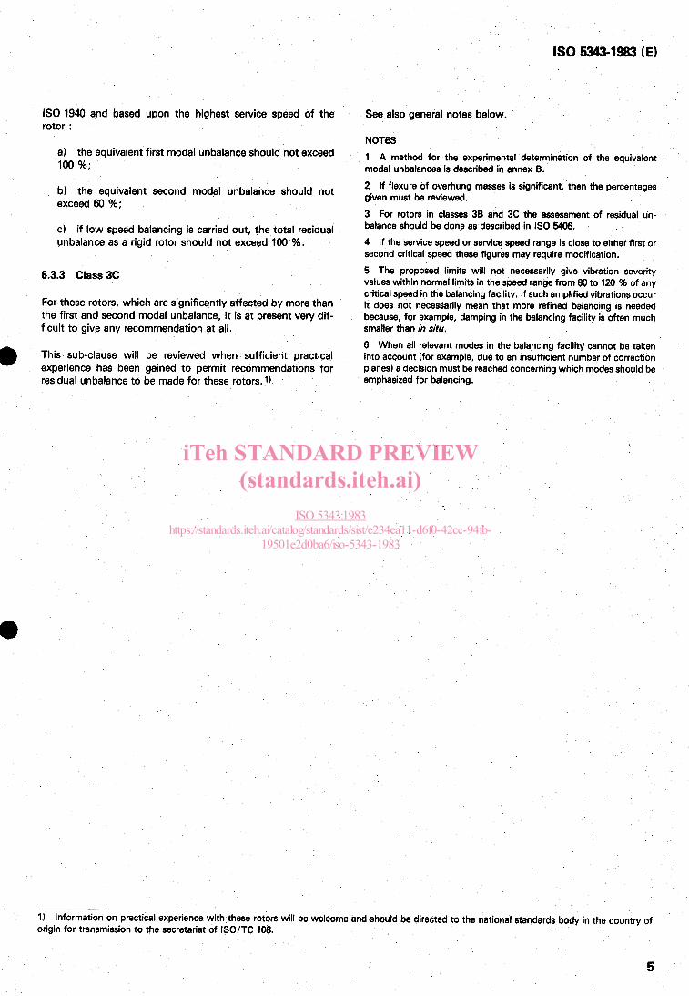
IS0 1940 and based upon the highest service speed of the rotor :
a) the equivalent first modal unbalance should not exceed loo %;
b) the equivalent second modal unbalance should not exceed 60 %;
c) if low speed balancing is carried out, the total residual unbalance as a rigid rotor should not exceed 100 %.
6.3.3 Class 3C
For these rotors, which are significantly affected by more than the first and second modal unbalance, it is at present very dif- ficult to give any recommendation at all.
This sub-clause will be reviewed when sufficient practical experience has been gained to permit recommendations for residual unbalance to be made for these rotors. 1)
IS0 5343-1983 (E)
See also general notes below.
NOTES 1 A method for the experimental determination of the equivalent modal unbalances is described in annex B. 2 If flexure of overhung masses is significant, then the percentages given must be reviewed. 3 For rotors in classes 38 and 3C the assessment of residual un- balance should be done as described in IS0 5406. 4 If the service speed or service speed range is close to either first or second critical speed these figures may require modification. 5 The proposed limits will not necessarily give vibration severity values within normal limits in the speed range from 80 to 120 % of any critical speed in the balancing facility. If such amplified vibrations occur it does not necessarily mean that more refined balancing is needed because, for example, damping in the balancing facility is often much smaller than in situ. 6 When all relevant modes in the balancing facility cannot be taken into account (for example, due to an insufficient number of correction planes) a decision must be reached concerning which modes should be emphasized for balancing.
1) Information on practical experience with these rotors will be welcome and should be directed to the national standards body in the country of origin for transmission to the secretariat of ISO/TC 108.
5
iTeh STANDARD PREVIEW(standards.iteh.ai)
ISO 5343:1983https://standards.iteh.ai/catalog/standards/sist/e234ea11-d6f0-42cc-94fb-
19501e2d0ba6/iso-5343-1983
IS0 5343-1983 (E)
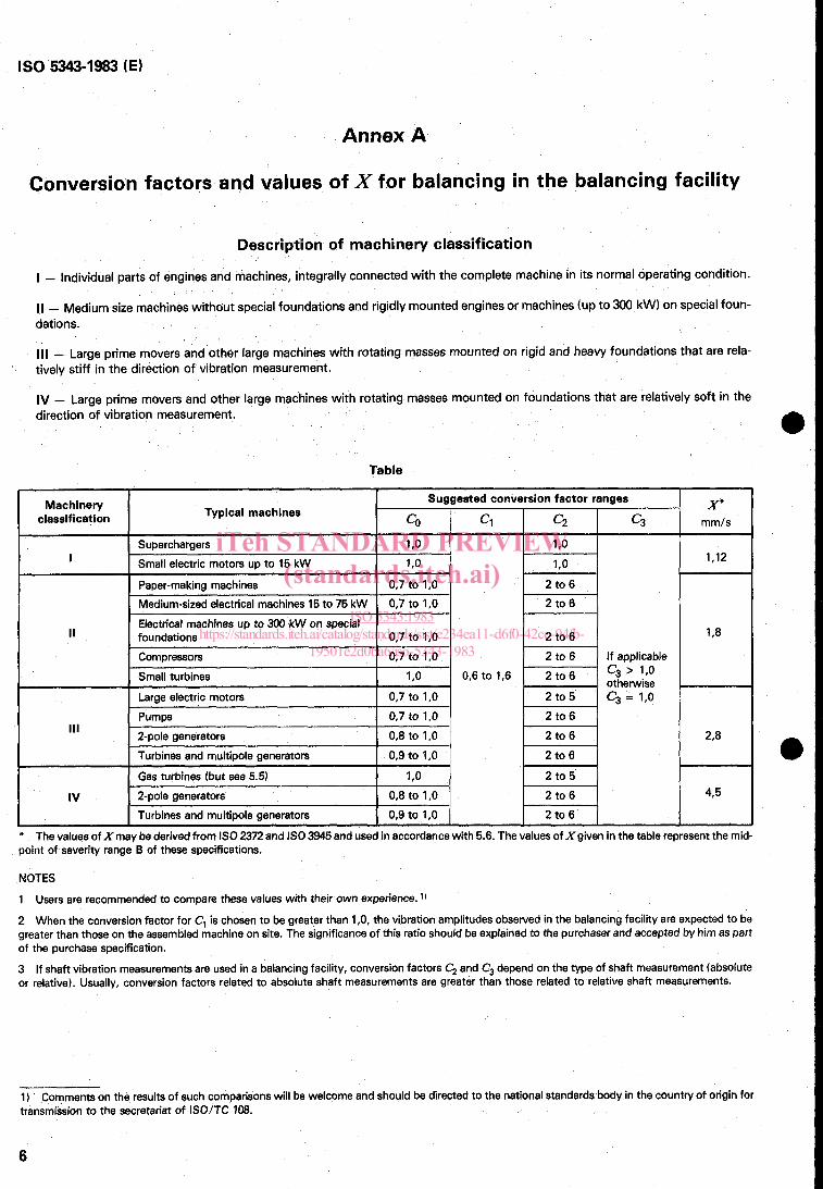
Annex A
Conversion factors and values of X for balancing in the balancing facility
Description of machinery classification
I - Individual parts of engines and machines, integrally connected with the complete machine in its normal operating condition.
II - Medium size machines without special foundations and rigidly mounted engines or machines (up to 300 kW) on special foun- dations.
111 - Large prime movers and other large machines with rotating masses mounted on rigid and heavy foundations that are rela- tively stiff in the direction of vibration measurement.
IV - Large prime movers and other large machines with rotating masses mounted on foundations that are relatively soft in the direction of vibration measurement.
Table
Machinery Suggested conversion factor ranges X" CO C1 c2 c3 mmls
1,12
Typical machines classification
Superchargers 1 ,O 1 ,O Small electric motors up to 15 kW 1,o 1,o Paper-making machines 0.7 to 1,0 2 to 6 Medium-sized electrical machines 15 to 75 kW 2 to 6
j I ;;;; 1 1 Il8 1 Electrical machines up to 300 kW on special
Compressors 0,7 to 1,0 if applicable
I
0,7 to 1 ,O
0,7 to 1,0 II foundations
0,6 to 1,6 '3 ' '*O 1 I otherwise Small turbines 1 ,O Large electric motors c3 = l,o 0,7 to 1,0
0,7tol ,O( 1 2;;; 1 Pumps 2-pole generators 0,8 to 1,0 I 2r8 I
U I Turbines and multipole generators I 0.9 to 1.0 I 2 t o 6 I I Gas turbines (but see 5.5) I 1,o I
IV I 2-po1e generators I 0,8to 1,0 I I Turbines and multipole generators I 0,9 to l,o I
t-451 2 to 6
4,5
* The values of Xmay be derived from IS0 2372 and IS0 3945 and used in accordance with 5.6. The values of Xgiven in the table represent the mid- point of severity range B of these specifications.
NOTES 1 Users are recommended to compare these values with their own experience. 2 When the conversion factor for C, is chosen to be greater than 1,0, the vibration amplitudes observed in the balancing facility are expected to be greater than those on the assembled machine on site. The significance of this ratio should be explained to the purchaser and accepted by him as part of the purchase specification. 3 If shaft vibration measurements are used in a balancing facility, conversion factors C, and C, depend on the type of shaft measurement (absolute or relative). Usually, conversion factors related to absolute shaft measurements are greater than those related to relative shaft measurements.
1) Comments on the results of such comparisons will be welcome and should be directed to the national standards body in the countfy of origin for transmission to the secretariat of ISO/TC 108.
6
iTeh STANDARD PREVIEW(standards.iteh.ai)
ISO 5343:1983https://standards.iteh.ai/catalog/standards/sist/e234ea11-d6f0-42cc-94fb-
19501e2d0ba6/iso-5343-1983
IS0 5343-1983 (E)
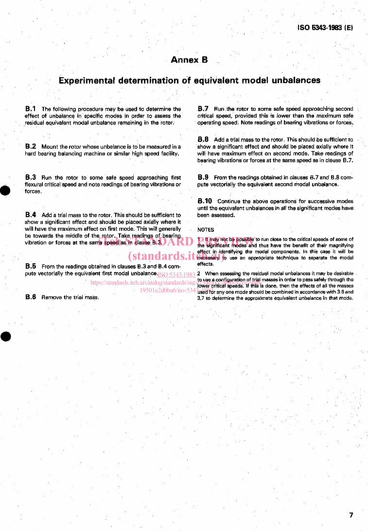
Annex B
Experimental determination of equivalent modal unbalances
B.l The following procedure may be used to determine the effect of unbalance in specific modes in order to assess the residual equivalent modal unbalance remaining in the rotor.
B.2 Mount the rotor whose unbalance is to be measured in a hard bearing balancing machine or similar high speed facility.
B.3 Run the rotor to some safe speed approaching first flexural critical speed and note readings of bearing vibrations or forces.
8.4 Add a trial mass to the rotor. This should be sufficient to show a significant effect and should be placed axially where it will have the maximum effect on first mode. This will generally be towards the middle of the rotor. Take readings of bearing vibration or forces at the same speed as in clause 8.3.
B.5 From the readings obtained in clauses 8.3 and 8.4 com- pute vectorially the equivalent first modal unbalance.
B.6 Remove the trial mass.
B.7 Run the rotor to some safe speed approaching second critical speed, provided this is lower than the maximum safe operating speed. Note readings of bearing vibrations or forces,
8.8 Add a trial mass to the rotor. This should be sufficient to show a significant effect and should be placed axially where it will have maximum effect on second mode. Take readings of bearing vibrations or forces at the same speed as in clause 8.7.
B.9 From the readings obtained in clauses 8.7 and 8.8 com- pute vectorially the equivalent second modal unbalance.
B.10 Continue the above operations for successive modes until the equivalent unbalances in all the significant modes have been assessed.
NOTES
1 It may not be possible to run close to the critical speeds of some of the significant modes and thus have the benefit of their magnifying effect in identifying the modal components. In this case it will be necessary to use an appropriate technique to separate the modal effects. 2 When assessing the residual modal unbalances it may be desirable to use a configuration of trial masses in order to pass safely through the lower critical speeds. If this is done, then the effects of all the masses used for any one mode should be combined in accordance with 3.6 and 3.7 to determine the approximate equivalent unbalance in that mode.
7
iTeh STANDARD PREVIEW(standards.iteh.ai)
ISO 5343:1983https://standards.iteh.ai/catalog/standards/sist/e234ea11-d6f0-42cc-94fb-
19501e2d0ba6/iso-5343-1983