INTERNATIONAL RESIDENTIAL CODE – PLUMBING RP1 …€¦ · · 2015-03-28INTERNATIONAL...
32
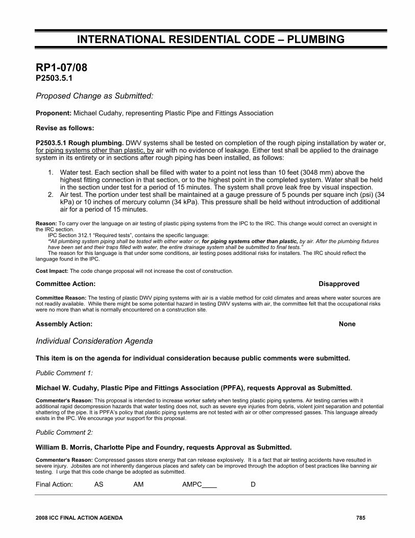
2008 ICC FINAL ACTION AGENDA 785 INTERNATIONAL RESIDENTIAL CODE – PLUMBING RP1-07/08 P2503.5.1 Proposed Change as Submitted: Proponent: Michael Cudahy, representing Plastic Pipe and Fittings Association Revise as follows: P2503.5.1 Rough plumbing. DWV systems shall be tested on completion of the rough piping installation by water or, for piping systems other than plastic, by air with no evidence of leakage. Either test shall be applied to the drainage system in its entirety or in sections after rough piping has been installed, as follows: 1. Water test. Each section shall be filled with water to a point not less than 10 feet (3048 mm) above the highest fitting connection in that section, or to the highest point in the completed system. Water shall be held in the section under test for a period of 15 minutes. The system shall prove leak free by visual inspection. 2. Air test. The portion under test shall be maintained at a gauge pressure of 5 pounds per square inch (psi) (34 kPa) or 10 inches of mercury column (34 kPa). This pressure shall be held without introduction of additional air for a period of 15 minutes. Reason: To carry over the language on air testing of plastic piping systems from the IPC to the IRC. This change would correct an oversight in the IRC section. IPC Section 312.1 “Required tests”, contains the specific language: “All plumbing system piping shall be tested with either water or, for piping systems other than plastic, by air. After the plumbing fixtures have been set and their traps filled with water, the entire drainage system shall be submitted to final tests.” The reason for this language is that under some conditions, air testing poses additional risks for installers. The IRC should reflect the language found in the IPC. Cost Impact: The code change proposal will not increase the cost of construction. Committee Action: Disapproved Committee Reason: The testing of plastic DWV piping systems with air is a viable method for cold climates and areas where water sources are not readily available. While there might be some potential hazard in testing DWV systems with air, the committee felt that the occupational risks were no more than what is normally encountered on a construction site. Assembly Action: None Individual Consideration Agenda This item is on the agenda for individual consideration because public comments were submitted. Public Comment 1: Michael W. Cudahy, Plastic Pipe and Fittings Association (PPFA), requests Approval as Submitted. Commenter=s Reason: This proposal is intended to increase worker safety when testing plastic piping systems. Air testing carries with it additional rapid decompression hazards that water testing does not, such as severe eye injuries from debris, violent joint separation and potential shattering of the pipe. It is PPFA’s policy that plastic piping systems are not tested with air or other compressed gasses. This language already exists in the IPC. We encourage your support for this proposal. Public Comment 2: William B. Morris, Charlotte Pipe and Foundry, requests Approval as Submitted. Commenter=s Reason: Compressed gasses store energy that can release explosively. It is a fact that air testing accidents have resulted in severe injury. Jobsites are not inherently dangerous places and safety can be improved through the adoption of best practices like banning air testing. I urge that this code change be adopted as submitted. Final Action: AS AM AMPC D
Transcript of INTERNATIONAL RESIDENTIAL CODE – PLUMBING RP1 …€¦ · · 2015-03-28INTERNATIONAL...
2008 ICC FINAL ACTION AGENDA 785
INTERNATIONAL RESIDENTIAL CODE – PLUMBING RP1-07/08 P2503.5.1 Proposed Change as Submitted: Proponent: Michael Cudahy, representing Plastic Pipe and Fittings Association
Revise as follows: P2503.5.1 Rough plumbing. DWV systems shall be tested on completion of the rough piping installation by water or, for piping systems other than plastic, by air with no evidence of leakage. Either test shall be applied to the drainage system in its entirety or in sections after rough piping has been installed, as follows:
1. Water test. Each section shall be filled with water to a point not less than 10 feet (3048 mm) above the highest fitting connection in that section, or to the highest point in the completed system. Water shall be held in the section under test for a period of 15 minutes. The system shall prove leak free by visual inspection.
2. Air test. The portion under test shall be maintained at a gauge pressure of 5 pounds per square inch (psi) (34 kPa) or 10 inches of mercury column (34 kPa). This pressure shall be held without introduction of additional air for a period of 15 minutes.
Reason: To carry over the language on air testing of plastic piping systems from the IPC to the IRC. This change would correct an oversight in the IRC section. IPC Section 312.1 “Required tests”, contains the specific language:
“All plumbing system piping shall be tested with either water or, for piping systems other than plastic, by air. After the plumbing fixtures have been set and their traps filled with water, the entire drainage system shall be submitted to final tests.”
The reason for this language is that under some conditions, air testing poses additional risks for installers. The IRC should reflect the language found in the IPC. Cost Impact: The code change proposal will not increase the cost of construction. Committee Action: Disapproved Committee Reason: The testing of plastic DWV piping systems with air is a viable method for cold climates and areas where water sources are not readily available. While there might be some potential hazard in testing DWV systems with air, the committee felt that the occupational risks were no more than what is normally encountered on a construction site. Assembly Action: None Individual Consideration Agenda This item is on the agenda for individual consideration because public comments were submitted. Public Comment 1: Michael W. Cudahy, Plastic Pipe and Fittings Association (PPFA), requests Approval as Submitted. Commenter=s Reason: This proposal is intended to increase worker safety when testing plastic piping systems. Air testing carries with it additional rapid decompression hazards that water testing does not, such as severe eye injuries from debris, violent joint separation and potential shattering of the pipe. It is PPFA’s policy that plastic piping systems are not tested with air or other compressed gasses. This language already exists in the IPC. We encourage your support for this proposal. Public Comment 2: William B. Morris, Charlotte Pipe and Foundry, requests Approval as Submitted. Commenter=s Reason: Compressed gasses store energy that can release explosively. It is a fact that air testing accidents have resulted in severe injury. Jobsites are not inherently dangerous places and safety can be improved through the adoption of best practices like banning air testing. I urge that this code change be adopted as submitted. Final Action: AS AM AMPC D
786 2008 ICC FINAL ACTION AGENDA
RP3-07/08 P2904 (New), Chapter 43 (New) Proposed Change as Submitted: Proponent: Tom Lariviere, Fire Department, Madison, MS, representing Fire & Life Safety Section of the International Association of Fire Chiefs (IAFC) 1. Add new section as follows:
SECTION P2904 MULTIPURPOSE FIRE SPRINKLER SYSTEMS
P2904.1 General. A multipurpose fire sprinkler system shall provide domestic water to both fire sprinklers and plumbing fixtures and shall be in accordance with NFPA 13D or Section P2904. Section P2904 shall be considered equivalent to NFPA 13D. P2904.1.1 Required sprinkler locations. Sprinklers shall be installed to protect all areas of a dwelling unit.
Exceptions:
1. Attics, crawl spaces, and normally unoccupied concealed spaces that do not contain fuel-fired appliances do not require sprinklers. In attics, crawl spaces, and normally unoccupied concealed spaces that contain fuel-fired equipment, a sprinkler shall be provided above the equipment; however, sprinklers shall not be required in the remainder of the space.
2. Clothes closets, linen closets and pantries not exceeding 24 square feet in area, with the smallest dimension not greater than 3 feet and having wall and ceiling surfaces of gypsum board.
3. Bathrooms not greater than 55 square feet in area. 4. Garages; carports; exterior porches; unheated entry areas, such as mud rooms, that are adjacent to an
exterior door; and similar areas.
P2904.2 Sprinklers. Sprinklers shall be listed residential sprinklers and shall be installed in accordance with the sprinkler manufacturer’s installation instructions.
P2904.2.1 Temperature rating and separation from heat sources. Except as provided for in Section P2904.2.2, sprinklers shall have a temperature rating of not less than 135°F and not more than 170°F. Sprinklers shall be separated from heat sources as required by the sprinkler manufacturer’s installation instructions.
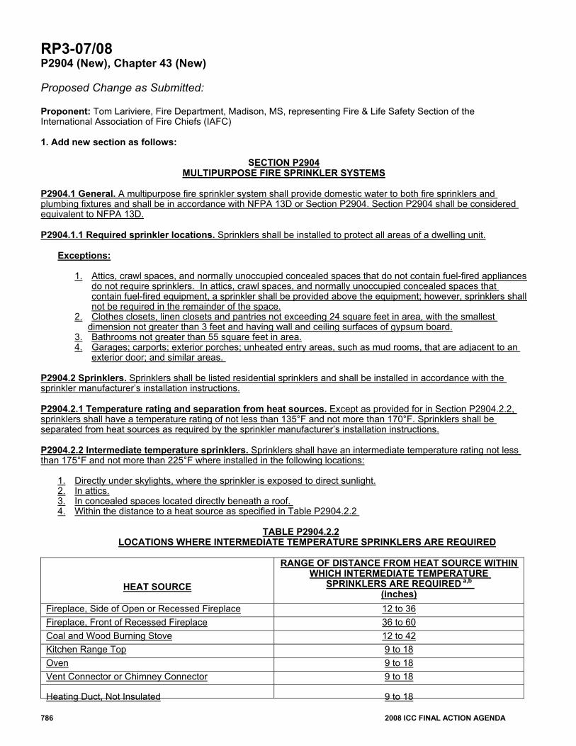
P2904.2.2 Intermediate temperature sprinklers. Sprinklers shall have an intermediate temperature rating not less than 175°F and not more than 225°F where installed in the following locations:
1. Directly under skylights, where the sprinkler is exposed to direct sunlight. 2. In attics. 3. In concealed spaces located directly beneath a roof. 4. Within the distance to a heat source as specified in Table P2904.2.2
TABLE P2904.2.2
LOCATIONS WHERE INTERMEDIATE TEMPERATURE SPRINKLERS ARE REQUIRED
HEAT SOURCE
RANGE OF DISTANCE FROM HEAT SOURCE WITHIN WHICH INTERMEDIATE TEMPERATURE
SPRINKLERS ARE REQUIRED a,b (inches)
Fireplace, Side of Open or Recessed Fireplace 12 to 36 Fireplace, Front of Recessed Fireplace 36 to 60 Coal and Wood Burning Stove 12 to 42 Kitchen Range Top 9 to 18 Oven 9 to 18 Vent Connector or Chimney Connector 9 to 18
Heating Duct, Not Insulated 9 to 18
2008 ICC FINAL ACTION AGENDA 787
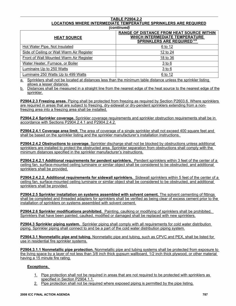
TABLE P2904.2.2LOCATIONS WHERE INTERMEDIATE TEMPERATURE SPRINKLERS ARE REQUIRED
(continued)
HEAT SOURCE RANGE OF DISTANCE FROM HEAT SOURCE WITHIN
WHICH INTERMEDIATE TEMPERATURE SPRINKLERS ARE REQUIRED a,b
(i h )Hot Water Pipe, Not Insulated 6 to 12 Side of Ceiling or Wall Warm Air Register 12 to 24 Front of Wall Mounted Warm Air Register 18 to 36 Water Heater, Furnace, or Boiler 3 to 6 Luminaire Up to 250 Watts 3 to 6 Luminaire 250 Watts Up to 499 Watts 6 to 12
a. Sprinklers shall not be located at distances less than the minimum table distance unless the sprinkler listing allows a lesser distance.
b. Distances shall be measured in a straight line from the nearest edge of the heat source to the nearest edge of the sprinkler.
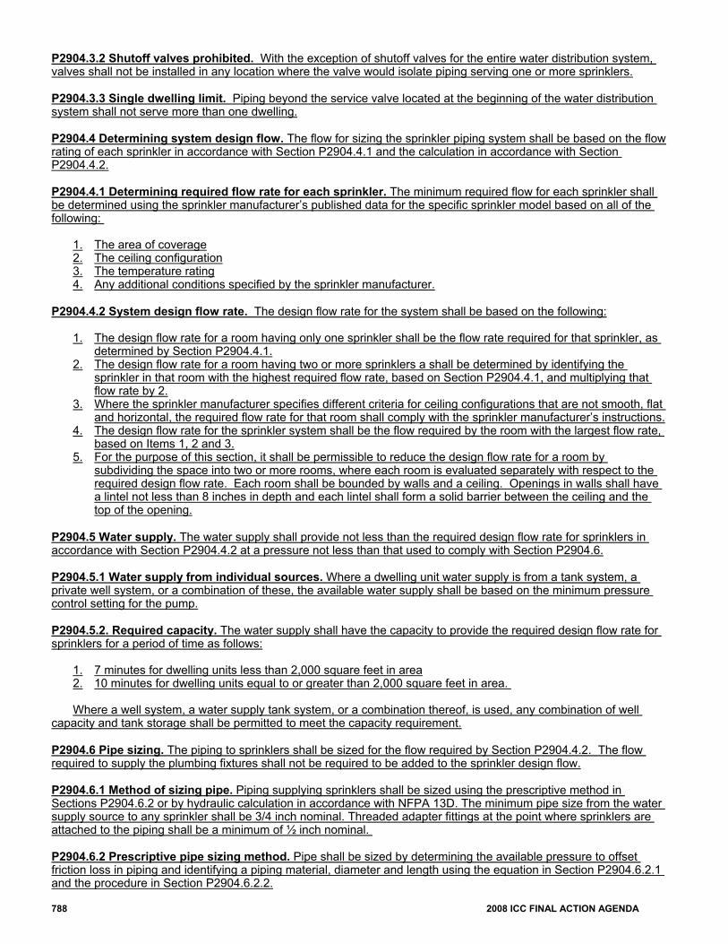
P2904.2.3 Freezing areas. Piping shall be protected from freezing as required by Section P2603.6. Where sprinklers are required in areas that are subject to freezing, dry-sidewall or dry-pendent sprinklers extending from a non-freezing area into a freezing area shall be installed.
P2904.2.4 Sprinkler coverage. Sprinkler coverage requirements and sprinkler obstruction requirements shall be in accordance with Sections P2904.2.4.1 and P2904.2.4.2.
P2904.2.4.1 Coverage area limit. The area of coverage of a single sprinkler shall not exceed 400 square feet and shall be based on the sprinkler listing and the sprinkler manufacturer’s installation instructions.
P2904.2.4.2 Obstructions to coverage. Sprinkler discharge shall not be blocked by obstructions unless additional sprinklers are installed to protect the obstructed area. Sprinkler separation from obstructions shall comply with the minimum distances specified in the sprinkler manufacturer’s instructions.
P2904.2.4.2.1 Additional requirements for pendent sprinklers. Pendent sprinklers within 3 feet of the center of a ceiling fan, surface-mounted ceiling luminaire or similar object shall be considered to be obstructed, and additional sprinklers shall be provided.
P2904.2.4.2.2. Additional requirements for sidewall sprinklers. Sidewall sprinklers within 5 feet of the center of a ceiling fan, surface-mounted ceiling luminaire or similar object shall be considered to be obstructed, and additional sprinklers shall be provided.
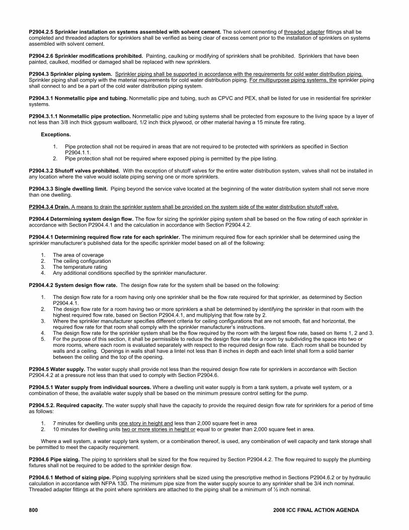
P2904.2.5 Sprinkler installation on systems assembled with solvent cement. The solvent cementing of fittings shall be completed and threaded adapters for sprinklers shall be verified as being clear of excess cement prior to the installation of sprinklers on systems assembled with solvent cement.
P2904.2.6 Sprinkler modifications prohibited. Painting, caulking or modifying of sprinklers shall be prohibited. Sprinklers that have been painted, caulked, modified or damaged shall be replaced with new sprinklers. P2904.3 Sprinkler piping system. Sprinkler piping shall comply with all requirements for cold water distribution piping. Sprinkler piping shall connect to and be a part of the cold water distribution piping system.
P2904.3.1 Nonmetallic pipe and tubing. Nonmetallic pipe and tubing, such as CPVC and PEX, shall be listed for use in residential fire sprinkler systems.
P2904.3.1.1 Nonmetallic pipe protection. Nonmetallic pipe and tubing systems shall be protected from exposure to the living space by a layer of not less than 3/8 inch thick gypsum wallboard, 1/2 inch thick plywood, or other material having a 15 minute fire rating.
Exceptions.
1. Pipe protection shall not be required in areas that are not required to be protected with sprinklers as
specified in Section P2904.1.1. 2. Pipe protection shall not be required where exposed piping is permitted by the pipe listing.
788 2008 ICC FINAL ACTION AGENDA
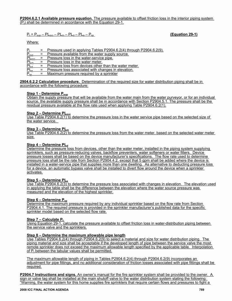
P2904.3.2 Shutoff valves prohibited. With the exception of shutoff valves for the entire water distribution system, valves shall not be installed in any location where the valve would isolate piping serving one or more sprinklers.
P2904.3.3 Single dwelling limit. Piping beyond the service valve located at the beginning of the water distribution system shall not serve more than one dwelling.
P2904.4 Determining system design flow. The flow for sizing the sprinkler piping system shall be based on the flow rating of each sprinkler in accordance with Section P2904.4.1 and the calculation in accordance with Section P2904.4.2. P2904.4.1 Determining required flow rate for each sprinkler. The minimum required flow for each sprinkler shall be determined using the sprinkler manufacturer’s published data for the specific sprinkler model based on all of the following:
1. The area of coverage 2. The ceiling configuration 3. The temperature rating 4. Any additional conditions specified by the sprinkler manufacturer.
P2904.4.2 System design flow rate. The design flow rate for the system shall be based on the following:
1. The design flow rate for a room having only one sprinkler shall be the flow rate required for that sprinkler, as
determined by Section P2904.4.1. 2. The design flow rate for a room having two or more sprinklers a shall be determined by identifying the
sprinkler in that room with the highest required flow rate, based on Section P2904.4.1, and multiplying that flow rate by 2.
3. Where the sprinkler manufacturer specifies different criteria for ceiling configurations that are not smooth, flat and horizontal, the required flow rate for that room shall comply with the sprinkler manufacturer’s instructions.
4. The design flow rate for the sprinkler system shall be the flow required by the room with the largest flow rate, based on Items 1, 2 and 3.
5. For the purpose of this section, it shall be permissible to reduce the design flow rate for a room by subdividing the space into two or more rooms, where each room is evaluated separately with respect to the required design flow rate. Each room shall be bounded by walls and a ceiling. Openings in walls shall have a lintel not less than 8 inches in depth and each lintel shall form a solid barrier between the ceiling and the top of the opening.
P2904.5 Water supply. The water supply shall provide not less than the required design flow rate for sprinklers in accordance with Section P2904.4.2 at a pressure not less than that used to comply with Section P2904.6. P2904.5.1 Water supply from individual sources. Where a dwelling unit water supply is from a tank system, a private well system, or a combination of these, the available water supply shall be based on the minimum pressure control setting for the pump.
P2904.5.2. Required capacity. The water supply shall have the capacity to provide the required design flow rate for sprinklers for a period of time as follows:
1. 7 minutes for dwelling units less than 2,000 square feet in area 2. 10 minutes for dwelling units equal to or greater than 2,000 square feet in area.
Where a well system, a water supply tank system, or a combination thereof, is used, any combination of well
capacity and tank storage shall be permitted to meet the capacity requirement. P2904.6 Pipe sizing. The piping to sprinklers shall be sized for the flow required by Section P2904.4.2. The flow required to supply the plumbing fixtures shall not be required to be added to the sprinkler design flow. P2904.6.1 Method of sizing pipe. Piping supplying sprinklers shall be sized using the prescriptive method in Sections P2904.6.2 or by hydraulic calculation in accordance with NFPA 13D. The minimum pipe size from the water supply source to any sprinkler shall be 3/4 inch nominal. Threaded adapter fittings at the point where sprinklers are attached to the piping shall be a minimum of ½ inch nominal. P2904.6.2 Prescriptive pipe sizing method. Pipe shall be sized by determining the available pressure to offset friction loss in piping and identifying a piping material, diameter and length using the equation in Section P2904.6.2.1 and the procedure in Section P2904.6.2.2.
2008 ICC FINAL ACTION AGENDA 789
P2904.6.2.1 Available pressure equation. The pressure available to offset friction loss in the interior piping system (Pt) shall be determined in accordance with the Equation 29-1.
Pt = Psup – PLsvc – PLm – PLd – PLe – Psp (Equation 29-1)
Where: Pt = Pressure used in applying Tables P2904.6.2(4) through P2904.6.2(9). Psup = Pressure available from the water supply source. PLsvc = Pressure loss in the water-service pipe. PLm = Pressure loss in the water meter. PLd = Pressure loss from devices other than the water meter. PLe = Pressure loss associated with changes in elevation. Psp = Maximum pressure required by a sprinkler
2904.6.2.2 Calculation procedure. Determination of the required size for water distribution piping shall be in accordance with the following procedure:
Step 1 - Determine Psup Obtain the supply pressure that will be available from the water main from the water purveyor, or for an individual source, the available supply pressure shall be in accordance with Section P2904.5.1. The pressure shall be the residual pressure available at the flow rate used when applying Table P2904.6.2(1).
Step 2 – Determine PLsvc Use Table P2904.6.2(1) to determine the pressure loss in the water service pipe based on the selected size of the water service.
Step 3 – Determine PLm Use Table P2904.6.2(2) to determine the pressure loss from the water meter. based on the selected water meter size.
Step 4 – Determine PLd Determine the pressure loss from devices, other than the water meter, installed in the piping system supplying sprinklers, such as pressure-reducing valves, backflow preventers, water softeners or water filters. Device pressure losses shall be based on the device manufacturer’s specifications. The flow rate used to determine pressure loss shall be the rate from Section P2904.4.2, except that 5 gpm shall be added where the device is installed in a water-service pipe that supplies more than one dwelling. As alternative to deducting pressure loss for a device, an automatic bypass valve shall be installed to divert flow around the device when a sprinkler activates.
Step 5 – Determine PLe Use Table P2904.6.2(3) to determine the pressure loss associated with changes in elevation. The elevation used in applying the table shall be the difference between the elevation where the water source pressure was measured and the elevation of the highest sprinkler.
Step 6 – Determine Psp Determine the maximum pressure required by any individual sprinkler based on the flow rate from Section P2904.4.1. The required pressure is provided in the sprinkler manufacturer’s published data for the specific sprinkler model based on the selected flow rate.
Step 7 – Calculate Pt Using Equation 29-1, calculate the pressure available to offset friction loss in water-distribution piping between the service valve and the sprinklers.
Step 8 – Determine the maximum allowable pipe length Use Tables P2904.6.2(4) through P2904.6.2(9) to select a material and size for water distribution piping. The piping material and size shall be acceptable if the developed length of pipe between the service valve the most remote sprinkler does not exceed the maximum allowable length specified by the applicable table. Interpolation of Pt between the tabular values shall be permitted. The maximum allowable length of piping in Tables P2904.6.2(4) through P2904.6.2(9) incorporates an adjustment for pipe fittings, and no additional consideration of friction losses associated with pipe fittings shall be required.
P2904.7 Instructions and signs. An owner’s manual for the fire sprinkler system shall be provided to the owner. A sign or valve tag shall be installed at the main shutoff valve to the water distribution system stating the following: “Warning, the water system for this home supplies fire sprinklers that require certain flows and pressures to fight a
790 2008 ICC FINAL ACTION AGENDA
fire. Devices that restrict the flow or decrease the pressure or automatically shut off the water to the fire sprinkler system, such as water softeners, filtration systems, and automatic shutoff valves, shall not be added to this system without a review of the fire sprinkler system by a fire protection specialist. Do not remove this sign.” P2904.8 Inspections. The water distribution system shall be inspected in accordance with Sections P2904.8.1 and P2904.8.2. P2904.8.1 Pre-concealment Inspection. The following items shall be verified prior to the concealment of any sprinkler system piping:
1. Sprinklers are installed in all areas as required by Section P2904.1.1. 2. Where sprinkler water spray patterns are obstructed by construction features, luminaires or ceiling fans,
additional sprinklers are installed as required by Section P2904.2.4.2. 3. Sprinklers are the correct temperature rating and are installed at or beyond the required separation distances
from heat sources as required by Sections P2904.2.1 and P2904.2.2. 4. The pipe size equals or exceeds the size used in applying Tables P2904.6.2(4) through P2904.6.2(9) or, if
the piping system was hydraulically calculated in accordance with Section P2904.6.1, the size used in the hydraulic calculation.
5. The pipe length does not exceed the length permitted by Tables P2904.6.2(4) through P2904.6.2(9) or, if the piping system was hydraulically calculated in accordance with Section P2904.6.1, pipe lengths and fittings do not exceed those used in the hydraulic calculation.
6. Non-metallic piping that conveys water to sprinklers is listed for use with fire sprinklers. 7. Piping is supported in accordance with the pipe manufacturer’s and sprinkler manufacturer’s installation
Instructions. 8. The piping system is tested in accordance with Section P2503.6
P2904.8.2 Final Inspection. The following items shall be verified upon completion of the system:
1. Sprinkler are not painted, damaged or otherwise hindered from operation. 2. Where a pump is required to provide water to the system, the pump starts automatically upon system water
demand. 3. Pressure reducing valves, water softeners, water filters or other impairments to water flow that were not part
of the original design have not been installed. 4. The sign or valve tag required by Section P2904.7 is installed and the owner’s manual for the system is
present.
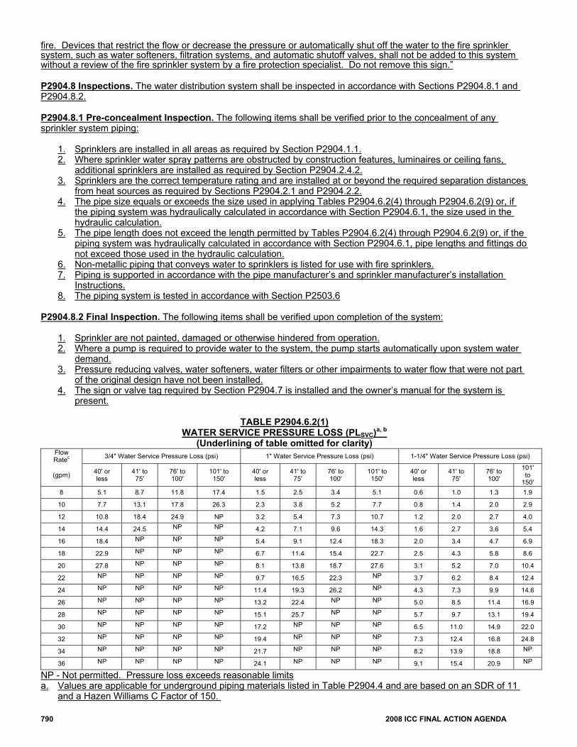
TABLE P2904.6.2(1) WATER SERVICE PRESSURE LOSS (PLSVC)a, b
(Underlining of table omitted for clarity) Flow Ratec 3/4" Water Service Pressure Loss (psi) 1" Water Service Pressure Loss (psi) 1-1/4" Water Service Pressure Loss (psi)
(gpm) 40' or less
41' to 75'
76' to 100'
101' to 150'
40' or less
41' to 75'
76' to 100'
101' to 150'
40' or less
41' to 75'
76' to 100'
101' to
150' 8 5.1 8.7 11.8 17.4 1.5 2.5 3.4 5.1 0.6 1.0 1.3 1.9
10 7.7 13.1 17.8 26.3 2.3 3.8 5.2 7.7 0.8 1.4 2.0 2.9
12 10.8 18.4 24.9 NP 3.2 5.4 7.3 10.7 1.2 2.0 2.7 4.0
14 14.4 24.5 NP NP 4.2 7.1 9.6 14.3 1.6 2.7 3.6 5.4
16 18.4 NP NP NP 5.4 9.1 12.4 18.3 2.0 3.4 4.7 6.9
18 22.9 NP NP NP 6.7 11.4 15.4 22.7 2.5 4.3 5.8 8.6
20 27.8 NP NP NP 8.1 13.8 18.7 27.6 3.1 5.2 7.0 10.4
22 NP NP NP NP 9.7 16.5 22.3 NP 3.7 6.2 8.4 12.4
24 NP NP NP NP 11.4 19.3 26.2 NP 4.3 7.3 9.9 14.6
26 NP NP NP NP 13.2 22.4 NP NP 5.0 8.5 11.4 16.9
28 NP NP NP NP 15.1 25.7 NP NP 5.7 9.7 13.1 19.4
30 NP NP NP NP 17.2 NP NP NP 6.5 11.0 14.9 22.0
32 NP NP NP NP 19.4 NP NP NP 7.3 12.4 16.8 24.8
34 NP NP NP NP 21.7 NP NP NP 8.2 13.9 18.8 NP
36 NP NP NP NP 24.1 NP NP NP 9.1 15.4 20.9 NP
NP - Not permitted. Pressure loss exceeds reasonable limits a. Values are applicable for underground piping materials listed in Table P2904.4 and are based on an SDR of 11
and a Hazen Williams C Factor of 150.
2008 ICC FINAL ACTION AGENDA 791
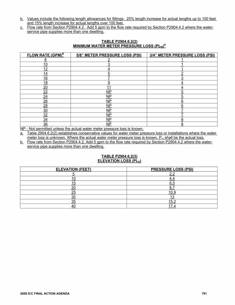
b. Values include the following length allowances for fittings: 25% length increase for actual lengths up to 100 feet and 15% length increase for actual lengths over 100 feet.
c. Flow rate from Section P2904.4.2. Add 5 gpm to the flow rate required by Section P2904.4.2 where the water-service pipe supplies more than one dwelling.
TABLE P2904.6.2(2)
MINIMUM WATER METER PRESSURE LOSS (PLM)A
FLOW RATE (GPM)B 5/8” METER PRESSURE LOSS (PSI) 3/4” METER PRESSURE LOSS (PSI)
8 2 1 10 3 1 12 4 1 14 5 2 16 7 3 18 9 4 20 11 4 22 NP 5 24 NP 5 26 NP 6 28 NP 6 30 NP 7 32 NP 7 34 NP 8 36 NP 8
NP - Not permitted unless the actual water meter pressure loss is known. a. Table 2904.6.2(2) establishes conservative values for water meter pressure loss or installations where the water
meter loss is unknown. Where the actual water meter pressure loss is known, Pm shall be the actual loss. b. Flow rate from Section P2904.4.2. Add 5 gpm to the flow rate required by Section P2904.4.2 where the water-
service pipe supplies more than one dwelling.
TABLE P2904.6.2(3) ELEVATION LOSS (PLE)
ELEVATION (FEET) PRESSURE LOSS (PSI) 5 2.2 10 4.4 15 6.5 20 8.7 25 10.9 30 13 35 15.2 40 17.4
792 2008 ICC FINAL ACTION AGENDA
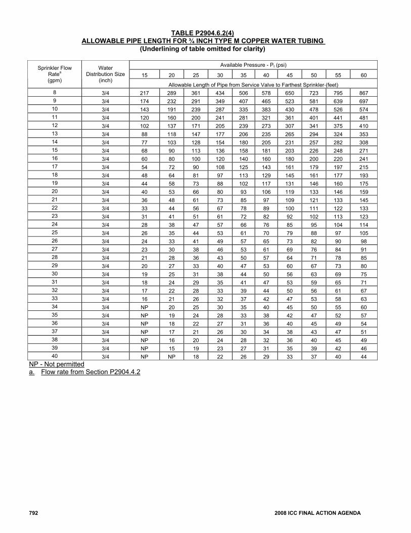
TABLE P2904.6.2(4) ALLOWABLE PIPE LENGTH FOR ¾ INCH TYPE M COPPER WATER TUBING
(Underlining of table omitted for clarity)
Available Pressure - Pt (psi)
15 20 25 30 35 40 45 50 55 60 Sprinkler Flow
Ratea (gpm)
Water Distribution Size
(inch) Allowable Length of Pipe from Service Valve to Farthest Sprinkler (feet)
8 3/4 217 289 361 434 506 578 650 723 795 867 9 3/4 174 232 291 349 407 465 523 581 639 697
10 3/4 143 191 239 287 335 383 430 478 526 574 11 3/4 120 160 200 241 281 321 361 401 441 481 12 3/4 102 137 171 205 239 273 307 341 375 410 13 3/4 88 118 147 177 206 235 265 294 324 353 14 3/4 77 103 128 154 180 205 231 257 282 308 15 3/4 68 90 113 136 158 181 203 226 248 271 16 3/4 60 80 100 120 140 160 180 200 220 241 17 3/4 54 72 90 108 125 143 161 179 197 215 18 3/4 48 64 81 97 113 129 145 161 177 193 19 3/4 44 58 73 88 102 117 131 146 160 175 20 3/4 40 53 66 80 93 106 119 133 146 159 21 3/4 36 48 61 73 85 97 109 121 133 145 22 3/4 33 44 56 67 78 89 100 111 122 133 23 3/4 31 41 51 61 72 82 92 102 113 123 24 3/4 28 38 47 57 66 76 85 95 104 114 25 3/4 26 35 44 53 61 70 79 88 97 105 26 3/4 24 33 41 49 57 65 73 82 90 98 27 3/4 23 30 38 46 53 61 69 76 84 91 28 3/4 21 28 36 43 50 57 64 71 78 85 29 3/4 20 27 33 40 47 53 60 67 73 80 30 3/4 19 25 31 38 44 50 56 63 69 75 31 3/4 18 24 29 35 41 47 53 59 65 71 32 3/4 17 22 28 33 39 44 50 56 61 67 33 3/4 16 21 26 32 37 42 47 53 58 63 34 3/4 NP 20 25 30 35 40 45 50 55 60 35 3/4 NP 19 24 28 33 38 42 47 52 57 36 3/4 NP 18 22 27 31 36 40 45 49 54 37 3/4 NP 17 21 26 30 34 38 43 47 51 38 3/4 NP 16 20 24 28 32 36 40 45 49 39 3/4 NP 15 19 23 27 31 35 39 42 46 40 3/4 NP NP 18 22 26 29 33 37 40 44
NP - Not permitted a. Flow rate from Section P2904.4.2
2008 ICC FINAL ACTION AGENDA 793
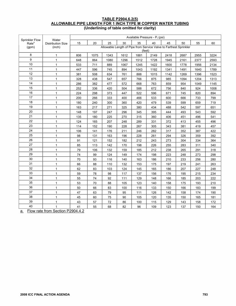
TABLE P2904.6.2(5) ALLOWABLE PIPE LENGTH FOR 1 INCH TYPE M COPPER WATER TUBING
(Underlining of table omitted for clarity)
Available Pressure - Pt (psi)
15 20 25 30 35 40 45 50 55 60 Sprinkler Flow
Ratea (gpm)
Water Distribution Size
(inch) Allowable Length of Pipe from Service Valve to Farthest Sprinkler (feet)
8 1 806 1075 1343 1612 1881 2149 2418 2687 2955 3224 9 1 648 864 1080 1296 1512 1728 1945 2161 2377 2593
10 1 533 711 889 1067 1245 1422 1600 1778 1956 2134 11 1 447 596 745 894 1043 1192 1341 1491 1640 1789 12 1 381 508 634 761 888 1015 1142 1269 1396 1523 13 1 328 438 547 657 766 875 985 1094 1204 1313 14 1 286 382 477 572 668 763 859 954 1049 1145 15 1 252 336 420 504 588 672 756 840 924 1008 16 1 224 298 373 447 522 596 671 745 820 894 17 1 200 266 333 400 466 533 600 666 733 799 18 1 180 240 300 360 420 479 539 599 659 719 19 1 163 217 271 325 380 434 488 542 597 651 20 1 148 197 247 296 345 395 444 493 543 592 21 1 135 180 225 270 315 360 406 451 496 541 22 1 124 165 207 248 289 331 372 413 455 496 23 1 114 152 190 228 267 305 343 381 419 457 24 1 106 141 176 211 246 282 317 352 387 422 25 1 98 131 163 196 228 261 294 326 359 392 26 1 91 121 152 182 212 243 273 304 334 364 27 1 85 113 142 170 198 226 255 283 311 340 28 1 79 106 132 159 185 212 238 265 291 318 29 1 74 99 124 149 174 198 223 248 273 298 30 1 70 93 116 140 163 186 210 233 256 280 31 1 66 88 110 132 153 175 197 219 241 263 32 1 62 83 103 124 145 165 186 207 227 248 33 1 59 78 98 117 137 156 176 195 215 234 34 1 55 74 92 111 129 148 166 185 203 222 35 1 53 70 88 105 123 140 158 175 193 210 36 1 50 66 83 100 116 133 150 166 183 199 37 1 47 63 79 95 111 126 142 158 174 190 38 1 45 60 75 90 105 120 135 150 165 181 39 1 43 57 72 86 100 115 129 143 158 172 40 1 41 55 68 82 96 109 123 137 150 164
a. Flow rate from Section P2904.4.2
794 2008 ICC FINAL ACTION AGENDA
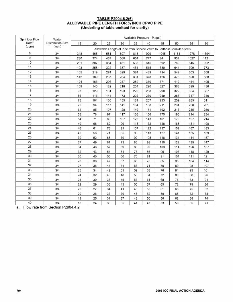
TABLE P2904.6.2(6) ALLOWABLE PIPE LENGTH FOR ¾ INCH CPVC PIPE
(Underling of table omitted for clarity)
Available Pressure - Pt (psi)
15 20 25 30 35 40 45 50 55 60 Sprinkler Flow
Ratea (gpm)
Water Distribution Size
(inch) Allowable Length of Pipe from Service Valve to Farthest Sprinkler (feet)
8 3/4 348 465 581 697 813 929 1045 1161 1278 1394 9 3/4 280 374 467 560 654 747 841 934 1027 1121
10 3/4 231 307 384 461 538 615 692 769 845 922 11 3/4 193 258 322 387 451 515 580 644 709 773 12 3/4 165 219 274 329 384 439 494 549 603 658 13 3/4 142 189 237 284 331 378 426 473 520 568 14 3/4 124 165 206 247 289 330 371 412 454 495 15 3/4 109 145 182 218 254 290 327 363 399 436 16 3/4 97 129 161 193 226 258 290 322 354 387 17 3/4 86 115 144 173 202 230 259 288 317 346 18 3/4 78 104 130 155 181 207 233 259 285 311 19 3/4 70 94 117 141 164 188 211 234 258 281 20 3/4 64 85 107 128 149 171 192 213 235 256 21 3/4 58 78 97 117 136 156 175 195 214 234 22 3/4 54 71 89 107 125 143 161 179 197 214 23 3/4 49 66 82 99 115 132 148 165 181 198 24 3/4 46 61 76 91 107 122 137 152 167 183 25 3/4 42 56 71 85 99 113 127 141 155 169 26 3/4 39 52 66 79 92 105 118 131 144 157 27 3/4 37 49 61 73 86 98 110 122 135 147 28 3/4 34 46 57 69 80 92 103 114 126 137 29 3/4 32 43 54 64 75 86 96 107 118 129 30 3/4 30 40 50 60 70 81 91 101 111 121 31 3/4 28 38 47 57 66 76 85 95 104 114 32 3/4 27 36 45 54 63 71 80 89 98 107 33 3/4 25 34 42 51 59 68 76 84 93 101 34 3/4 24 32 40 48 56 64 72 80 88 96 35 3/4 23 30 38 45 53 61 68 76 83 91 36 3/4 22 29 36 43 50 57 65 72 79 86 37 3/4 20 27 34 41 48 55 61 68 75 82 38 3/4 20 26 33 39 46 52 59 65 72 78 39 3/4 19 25 31 37 43 50 56 62 68 74 40 3/4 18 24 30 35 41 47 53 59 65 71
a. Flow rate from Section P2904.4.2

2008 ICC FINAL ACTION AGENDA 795
TABLE P2904.6.2(7) ALLOWABLE PIPE LENGTH FOR 1 INCH CPVC PIPE
(Underlining of table omitted for clarity)
Available Pressure - Pt (psi) 15 20 25 30 35 40 45 50 55 60
Sprinkler Flow Ratea
(gpm)
Water Distribution
Size (inch)
Allowable Length of Pipe from Service Valve to Farthest Sprinkler (feet)
8 1 1049 1398 1748 2098 2447 2797 3146 3496 3845 4195 9 1 843 1125 1406 1687 1968 2249 2530 2811 3093 3374
10 1 694 925 1157 1388 1619 1851 2082 2314 2545 2776 11 1 582 776 970 1164 1358 1552 1746 1940 2133 2327 12 1 495 660 826 991 1156 1321 1486 1651 1816 1981 13 1 427 570 712 854 997 1139 1281 1424 1566 1709 14 1 372 497 621 745 869 993 1117 1241 1366 1490 15 1 328 437 546 656 765 874 983 1093 1202 1311 16 1 291 388 485 582 679 776 873 970 1067 1164 17 1 260 347 433 520 607 693 780 867 954 1040 18 1 234 312 390 468 546 624 702 780 858 936 19 1 212 282 353 423 494 565 635 706 776 847 20 1 193 257 321 385 449 513 578 642 706 770 21 1 176 235 293 352 410 469 528 586 645 704 22 1 161 215 269 323 377 430 484 538 592 646 23 1 149 198 248 297 347 396 446 496 545 595 24 1 137 183 229 275 321 366 412 458 504 550 25 1 127 170 212 255 297 340 382 425 467 510 26 1 118 158 197 237 276 316 355 395 434 474 27 1 111 147 184 221 258 295 332 368 405 442 28 1 103 138 172 207 241 275 310 344 379 413 29 1 97 129 161 194 226 258 290 323 355 387 30 1 91 121 152 182 212 242 273 303 333 364 31 1 86 114 143 171 200 228 257 285 314 342 32 1 81 108 134 161 188 215 242 269 296 323 33 1 76 102 127 152 178 203 229 254 280 305 34 1 72 96 120 144 168 192 216 240 265 289 35 1 68 91 114 137 160 182 205 228 251 273 36 1 65 87 108 130 151 173 195 216 238 260 37 1 62 82 103 123 144 165 185 206 226 247 38 1 59 78 98 117 137 157 176 196 215 235 39 1 56 75 93 112 131 149 168 187 205 224 40 1 53 71 89 107 125 142 160 178 196 214
a. Flow rate from Section P2904.4.2
796 2008 ICC FINAL ACTION AGENDA
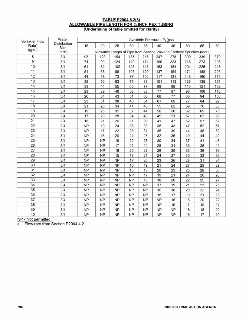
TABLE P2904.6.2(8) ALLOWABLE PIPE LENGTH FOR ¾ INCH PEX TUBING
(Underlining of table omitted for clarity)
Available Pressure - Pt (psi) 15 20 25 30 35 40 45 50 55 60
Sprinkler Flow Ratea (gpm)
Water Distribution
Size (inch) Allowable Length of Pipe from Service Valve to Farthest Sprinkler (feet)
8 3/4 93 123 154 185 216 247 278 309 339 370 9 3/4 74 99 124 149 174 199 223 248 273 298 10 3/4 61 82 102 123 143 163 184 204 225 245 11 3/4 51 68 86 103 120 137 154 171 188 205 12 3/4 44 58 73 87 102 117 131 146 160 175 13 3/4 38 50 63 75 88 101 113 126 138 151 14 3/4 33 44 55 66 77 88 99 110 121 132 15 3/4 29 39 48 58 68 77 87 96 106 116 16 3/4 26 34 43 51 60 68 77 86 94 103 17 3/4 23 31 38 46 54 61 69 77 84 92 18 3/4 21 28 34 41 48 55 62 69 76 83 19 3/4 19 25 31 37 44 50 56 62 69 75 20 3/4 17 23 28 34 40 45 51 57 62 68 21 3/4 16 21 26 31 36 41 47 52 57 62 22 3/4 NP 19 24 28 33 38 43 47 52 57 23 3/4 NP 17 22 26 31 35 39 44 48 52 24 3/4 NP 16 20 24 28 32 36 40 44 49 25 3/4 NP NP 19 22 26 30 34 37 41 45 26 3/4 NP NP 17 21 24 28 31 35 38 42 27 3/4 NP NP 16 20 23 26 29 33 36 39 28 3/4 NP NP 15 18 21 24 27 30 33 36 29 3/4 NP NP NP 17 20 23 26 28 31 34 30 3/4 NP NP NP 16 19 21 24 27 29 32 31 3/4 NP NP NP 15 18 20 23 25 28 30 32 3/4 NP NP NP NP 17 19 21 24 26 28 33 3/4 NP NP NP NP 16 18 20 22 25 27 34 3/4 NP NP NP NP NP 17 19 21 23 25 35 3/4 NP NP NP NP NP 16 18 20 22 24 36 3/4 NP NP NP NP NP 15 17 19 21 23 37 3/4 NP NP NP NP NP NP 16 18 20 22 38 3/4 NP NP NP NP NP NP 16 17 19 21 39 3/4 NP NP NP NP NP NP NP 16 18 20 40 3/4 NP NP NP NP NP NP NP 16 17 19
NP - Not permitted. a. Flow rate from Section P2904.4.2.
2008 ICC FINAL ACTION AGENDA 797
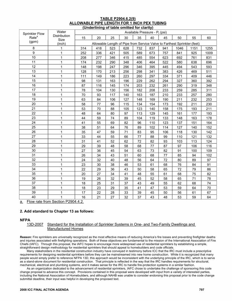
TABLE P2904.6.2(9) ALLOWABLE PIPE LENGTH FOR 1 INCH PEX TUBING
(Underlining of table omitted for clarity) Available Pressure - Pt (psi)
15 20 25 30 35 40 45 50 55 60 Sprinkler Flow
Ratea (gpm)
Water Distribution
Size (inch) Allowable Length of Pipe from Service Valve to Farthest Sprinkler (feet)
8 1 314 418 523 628 732 837 941 1046 1151 1255 9 1 252 336 421 505 589 673 757 841 925 1009
10 1 208 277 346 415 485 554 623 692 761 831 11 1 174 232 290 348 406 464 522 580 638 696 12 1 148 198 247 296 346 395 445 494 543 593 13 1 128 170 213 256 298 341 383 426 469 511 14 1 111 149 186 223 260 297 334 371 409 446 15 1 98 131 163 196 229 262 294 327 360 392 16 1 87 116 145 174 203 232 261 290 319 348 17 1 78 104 130 156 182 208 233 259 285 311 18 1 70 93 117 140 163 187 210 233 257 280 19 1 63 84 106 127 148 169 190 211 232 253 20 1 58 77 96 115 134 154 173 192 211 230 21 1 53 70 88 105 123 140 158 175 193 211 22 1 48 64 80 97 113 129 145 161 177 193 23 1 44 59 74 89 104 119 133 148 163 178 24 1 41 55 69 82 96 110 123 137 151 164 25 1 38 51 64 76 89 102 114 127 140 152 26 1 35 47 59 71 83 95 106 118 130 142 27 1 33 44 55 66 77 88 99 110 121 132 28 1 31 41 52 62 72 82 93 103 113 124 29 1 29 39 48 58 68 77 87 97 106 116 30 1 27 36 45 54 63 73 82 91 100 109 31 1 26 34 43 51 60 68 77 85 94 102 32 1 24 32 40 48 56 64 72 80 89 97 33 1 23 30 38 46 53 61 68 76 84 91 34 1 22 29 36 43 50 58 65 72 79 86 35 1 20 27 34 41 48 55 61 68 75 82 36 1 19 26 32 39 45 52 58 65 71 78 37 1 18 25 31 37 43 49 55 62 68 74 38 1 18 23 29 35 41 47 53 59 64 70 39 1 17 22 28 33 39 45 50 56 61 67 40 1 16 21 27 32 37 43 48 53 59 64
a. Flow rate from Section P2904.4.2. 2. Add standard to Chapter 13 as follows: NFPA
13D-2007 Standard for the Installation of Sprinkler Systems in One- and Two-Family Dwellings and Manufactured Homes
Reason: Fire sprinklers are universally recognized as the most effective means of reducing America’s fire losses and preventing firefighter deaths and injuries associated with firefighting operations. Both of these objectives are fundamental to the mission of the International Association of Fire Chiefs (IAFC). Through this proposal, the IAFC hopes to encourage more widespread use of residential sprinklers by establishing a simple, straightforward design methodology for residential sprinklers that should appeal to homebuilders and code officials. Many stakeholders in the residential construction industry have conveyed in testimony before ICC that the IRC must include a prescriptive requirements for designing residential sprinklers before they can be mainstreamed into new home construction. While it is recognized that many people would simply prefer to reference NFPA 13D, this approach would be inconsistent with the underlying principle of the IRC, which is to serve as a stand-alone document for residential construction. That principle is reflected in the way that the IRC handles requirements for structural, mechanical, electrical and plumbing systems, and it makes sense for the IRC to handle fire-protection systems in a similar fashion. As an organization dedicated to the advancement of residential sprinklers, IAFC chose to undertake the challenge of sponsoring this code change proposal to advance this concept. Provisions contained in this proposal were developed with input from a variety of interested parties, including the National Association of Homebuilders, and although NAHB was unable to consider endorsing this proposal prior to the code change submittal deadline, their input was helpful in developing the proposed text.
798 2008 ICC FINAL ACTION AGENDA
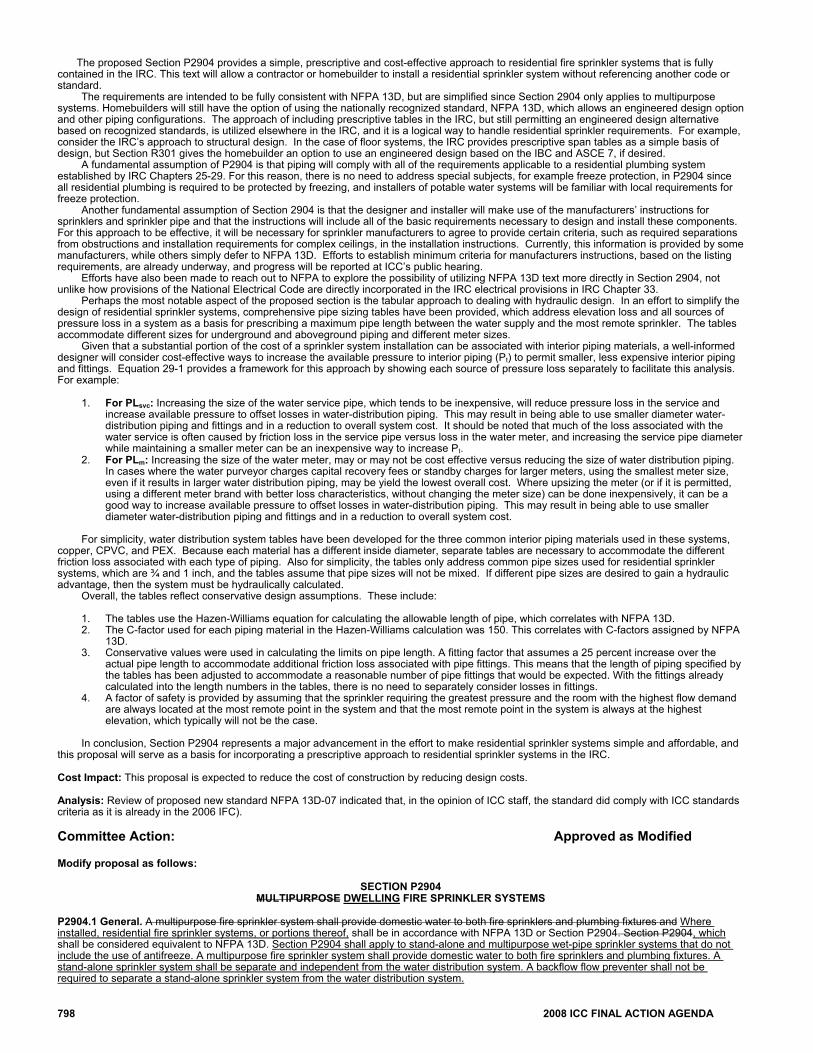
The proposed Section P2904 provides a simple, prescriptive and cost-effective approach to residential fire sprinkler systems that is fully contained in the IRC. This text will allow a contractor or homebuilder to install a residential sprinkler system without referencing another code or standard. The requirements are intended to be fully consistent with NFPA 13D, but are simplified since Section 2904 only applies to multipurpose systems. Homebuilders will still have the option of using the nationally recognized standard, NFPA 13D, which allows an engineered design option and other piping configurations. The approach of including prescriptive tables in the IRC, but still permitting an engineered design alternative based on recognized standards, is utilized elsewhere in the IRC, and it is a logical way to handle residential sprinkler requirements. For example, consider the IRC’s approach to structural design. In the case of floor systems, the IRC provides prescriptive span tables as a simple basis of design, but Section R301 gives the homebuilder an option to use an engineered design based on the IBC and ASCE 7, if desired. A fundamental assumption of P2904 is that piping will comply with all of the requirements applicable to a residential plumbing system established by IRC Chapters 25-29. For this reason, there is no need to address special subjects, for example freeze protection, in P2904 since all residential plumbing is required to be protected by freezing, and installers of potable water systems will be familiar with local requirements for freeze protection. Another fundamental assumption of Section 2904 is that the designer and installer will make use of the manufacturers’ instructions for sprinklers and sprinkler pipe and that the instructions will include all of the basic requirements necessary to design and install these components. For this approach to be effective, it will be necessary for sprinkler manufacturers to agree to provide certain criteria, such as required separations from obstructions and installation requirements for complex ceilings, in the installation instructions. Currently, this information is provided by some manufacturers, while others simply defer to NFPA 13D. Efforts to establish minimum criteria for manufacturers instructions, based on the listing requirements, are already underway, and progress will be reported at ICC’s public hearing. Efforts have also been made to reach out to NFPA to explore the possibility of utilizing NFPA 13D text more directly in Section 2904, not unlike how provisions of the National Electrical Code are directly incorporated in the IRC electrical provisions in IRC Chapter 33. Perhaps the most notable aspect of the proposed section is the tabular approach to dealing with hydraulic design. In an effort to simplify the design of residential sprinkler systems, comprehensive pipe sizing tables have been provided, which address elevation loss and all sources of pressure loss in a system as a basis for prescribing a maximum pipe length between the water supply and the most remote sprinkler. The tables accommodate different sizes for underground and aboveground piping and different meter sizes. Given that a substantial portion of the cost of a sprinkler system installation can be associated with interior piping materials, a well-informed designer will consider cost-effective ways to increase the available pressure to interior piping (Pt) to permit smaller, less expensive interior piping and fittings. Equation 29-1 provides a framework for this approach by showing each source of pressure loss separately to facilitate this analysis. For example:
1. For PLsvc: Increasing the size of the water service pipe, which tends to be inexpensive, will reduce pressure loss in the service and increase available pressure to offset losses in water-distribution piping. This may result in being able to use smaller diameter water-distribution piping and fittings and in a reduction to overall system cost. It should be noted that much of the loss associated with the water service is often caused by friction loss in the service pipe versus loss in the water meter, and increasing the service pipe diameter while maintaining a smaller meter can be an inexpensive way to increase Pt.
2. For PLm: Increasing the size of the water meter, may or may not be cost effective versus reducing the size of water distribution piping. In cases where the water purveyor charges capital recovery fees or standby charges for larger meters, using the smallest meter size, even if it results in larger water distribution piping, may be yield the lowest overall cost. Where upsizing the meter (or if it is permitted, using a different meter brand with better loss characteristics, without changing the meter size) can be done inexpensively, it can be a good way to increase available pressure to offset losses in water-distribution piping. This may result in being able to use smaller diameter water-distribution piping and fittings and in a reduction to overall system cost.
For simplicity, water distribution system tables have been developed for the three common interior piping materials used in these systems,
copper, CPVC, and PEX. Because each material has a different inside diameter, separate tables are necessary to accommodate the different friction loss associated with each type of piping. Also for simplicity, the tables only address common pipe sizes used for residential sprinkler systems, which are ¾ and 1 inch, and the tables assume that pipe sizes will not be mixed. If different pipe sizes are desired to gain a hydraulic advantage, then the system must be hydraulically calculated. Overall, the tables reflect conservative design assumptions. These include:
1. The tables use the Hazen-Williams equation for calculating the allowable length of pipe, which correlates with NFPA 13D. 2. The C-factor used for each piping material in the Hazen-Williams calculation was 150. This correlates with C-factors assigned by NFPA
13D. 3. Conservative values were used in calculating the limits on pipe length. A fitting factor that assumes a 25 percent increase over the
actual pipe length to accommodate additional friction loss associated with pipe fittings. This means that the length of piping specified by the tables has been adjusted to accommodate a reasonable number of pipe fittings that would be expected. With the fittings already calculated into the length numbers in the tables, there is no need to separately consider losses in fittings.
4. A factor of safety is provided by assuming that the sprinkler requiring the greatest pressure and the room with the highest flow demand are always located at the most remote point in the system and that the most remote point in the system is always at the highest elevation, which typically will not be the case.
In conclusion, Section P2904 represents a major advancement in the effort to make residential sprinkler systems simple and affordable, and this proposal will serve as a basis for incorporating a prescriptive approach to residential sprinkler systems in the IRC. Cost Impact: This proposal is expected to reduce the cost of construction by reducing design costs. Analysis: Review of proposed new standard NFPA 13D-07 indicated that, in the opinion of ICC staff, the standard did comply with ICC standards criteria as it is already in the 2006 IFC). Committee Action: Approved as Modified Modify proposal as follows:
SECTION P2904 MULTIPURPOSE DWELLING FIRE SPRINKLER SYSTEMS
P2904.1 General. A multipurpose fire sprinkler system shall provide domestic water to both fire sprinklers and plumbing fixtures and Where installed, residential fire sprinkler systems, or portions thereof, shall be in accordance with NFPA 13D or Section P2904. Section P2904, which shall be considered equivalent to NFPA 13D. Section P2904 shall apply to stand-alone and multipurpose wet-pipe sprinkler systems that do not include the use of antifreeze. A multipurpose fire sprinkler system shall provide domestic water to both fire sprinklers and plumbing fixtures. A stand-alone sprinkler system shall be separate and independent from the water distribution system. A backflow flow preventer shall not be required to separate a stand-alone sprinkler system from the water distribution system.
2008 ICC FINAL ACTION AGENDA 799
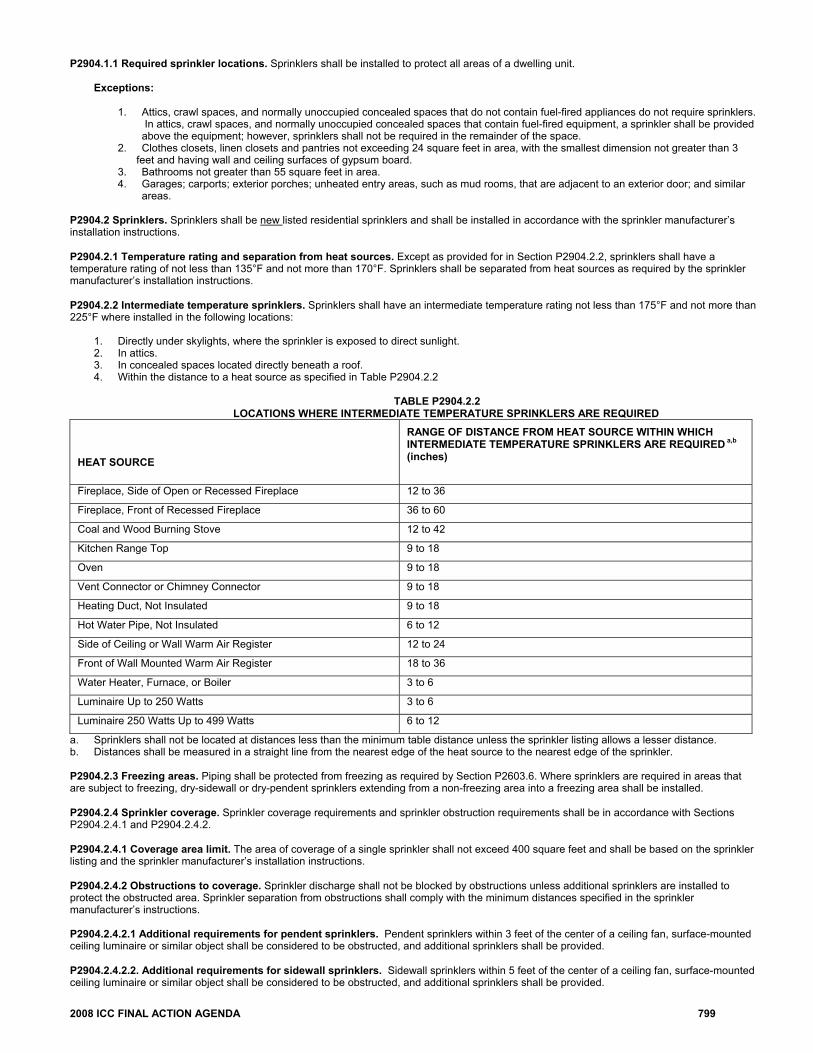
P2904.1.1 Required sprinkler locations. Sprinklers shall be installed to protect all areas of a dwelling unit.
Exceptions:
1. Attics, crawl spaces, and normally unoccupied concealed spaces that do not contain fuel-fired appliances do not require sprinklers. In attics, crawl spaces, and normally unoccupied concealed spaces that contain fuel-fired equipment, a sprinkler shall be provided above the equipment; however, sprinklers shall not be required in the remainder of the space.
2. Clothes closets, linen closets and pantries not exceeding 24 square feet in area, with the smallest dimension not greater than 3 feet and having wall and ceiling surfaces of gypsum board.
3. Bathrooms not greater than 55 square feet in area. 4. Garages; carports; exterior porches; unheated entry areas, such as mud rooms, that are adjacent to an exterior door; and similar
areas.
P2904.2 Sprinklers. Sprinklers shall be new listed residential sprinklers and shall be installed in accordance with the sprinkler manufacturer’s installation instructions.
P2904.2.1 Temperature rating and separation from heat sources. Except as provided for in Section P2904.2.2, sprinklers shall have a temperature rating of not less than 135°F and not more than 170°F. Sprinklers shall be separated from heat sources as required by the sprinkler manufacturer’s installation instructions.
P2904.2.2 Intermediate temperature sprinklers. Sprinklers shall have an intermediate temperature rating not less than 175°F and not more than 225°F where installed in the following locations:
1. Directly under skylights, where the sprinkler is exposed to direct sunlight. 2. In attics. 3. In concealed spaces located directly beneath a roof. 4. Within the distance to a heat source as specified in Table P2904.2.2
TABLE P2904.2.2
LOCATIONS WHERE INTERMEDIATE TEMPERATURE SPRINKLERS ARE REQUIRED
HEAT SOURCE
RANGE OF DISTANCE FROM HEAT SOURCE WITHIN WHICH INTERMEDIATE TEMPERATURE SPRINKLERS ARE REQUIRED a,b (inches)
Fireplace, Side of Open or Recessed Fireplace 12 to 36
Fireplace, Front of Recessed Fireplace 36 to 60
Coal and Wood Burning Stove 12 to 42
Kitchen Range Top 9 to 18
Oven 9 to 18
Vent Connector or Chimney Connector 9 to 18
Heating Duct, Not Insulated 9 to 18
Hot Water Pipe, Not Insulated 6 to 12
Side of Ceiling or Wall Warm Air Register 12 to 24
Front of Wall Mounted Warm Air Register 18 to 36
Water Heater, Furnace, or Boiler 3 to 6
Luminaire Up to 250 Watts 3 to 6
Luminaire 250 Watts Up to 499 Watts 6 to 12
a. Sprinklers shall not be located at distances less than the minimum table distance unless the sprinkler listing allows a lesser distance. b. Distances shall be measured in a straight line from the nearest edge of the heat source to the nearest edge of the sprinkler. P2904.2.3 Freezing areas. Piping shall be protected from freezing as required by Section P2603.6. Where sprinklers are required in areas that are subject to freezing, dry-sidewall or dry-pendent sprinklers extending from a non-freezing area into a freezing area shall be installed.
P2904.2.4 Sprinkler coverage. Sprinkler coverage requirements and sprinkler obstruction requirements shall be in accordance with Sections P2904.2.4.1 and P2904.2.4.2.
P2904.2.4.1 Coverage area limit. The area of coverage of a single sprinkler shall not exceed 400 square feet and shall be based on the sprinkler listing and the sprinkler manufacturer’s installation instructions.
P2904.2.4.2 Obstructions to coverage. Sprinkler discharge shall not be blocked by obstructions unless additional sprinklers are installed to protect the obstructed area. Sprinkler separation from obstructions shall comply with the minimum distances specified in the sprinkler manufacturer’s instructions.
P2904.2.4.2.1 Additional requirements for pendent sprinklers. Pendent sprinklers within 3 feet of the center of a ceiling fan, surface-mounted ceiling luminaire or similar object shall be considered to be obstructed, and additional sprinklers shall be provided.
P2904.2.4.2.2. Additional requirements for sidewall sprinklers. Sidewall sprinklers within 5 feet of the center of a ceiling fan, surface-mounted ceiling luminaire or similar object shall be considered to be obstructed, and additional sprinklers shall be provided.
800 2008 ICC FINAL ACTION AGENDA
P2904.2.5 Sprinkler installation on systems assembled with solvent cement. The solvent cementing of threaded adapter fittings shall be completed and threaded adapters for sprinklers shall be verified as being clear of excess cement prior to the installation of sprinklers on systems assembled with solvent cement.
P2904.2.6 Sprinkler modifications prohibited. Painting, caulking or modifying of sprinklers shall be prohibited. Sprinklers that have been painted, caulked, modified or damaged shall be replaced with new sprinklers. P2904.3 Sprinkler piping system. Sprinkler piping shall be supported in accordance with the requirements for cold water distribution piping. Sprinkler piping shall comply with the material requirements for cold water distribution piping. For multipurpose piping systems, the sprinkler piping shall connect to and be a part of the cold water distribution piping system.
P2904.3.1 Nonmetallic pipe and tubing. Nonmetallic pipe and tubing, such as CPVC and PEX, shall be listed for use in residential fire sprinkler systems.
P2904.3.1.1 Nonmetallic pipe protection. Nonmetallic pipe and tubing systems shall be protected from exposure to the living space by a layer of not less than 3/8 inch thick gypsum wallboard, 1/2 inch thick plywood, or other material having a 15 minute fire rating.
Exceptions.
1. Pipe protection shall not be required in areas that are not required to be protected with sprinklers as specified in Section
P2904.1.1. 2. Pipe protection shall not be required where exposed piping is permitted by the pipe listing.
P2904.3.2 Shutoff valves prohibited. With the exception of shutoff valves for the entire water distribution system, valves shall not be installed in any location where the valve would isolate piping serving one or more sprinklers.
P2904.3.3 Single dwelling limit. Piping beyond the service valve located at the beginning of the water distribution system shall not serve more than one dwelling. P2904.3.4 Drain. A means to drain the sprinkler system shall be provided on the system side of the water distribution shutoff valve.
P2904.4 Determining system design flow. The flow for sizing the sprinkler piping system shall be based on the flow rating of each sprinkler in accordance with Section P2904.4.1 and the calculation in accordance with Section P2904.4.2. P2904.4.1 Determining required flow rate for each sprinkler. The minimum required flow for each sprinkler shall be determined using the sprinkler manufacturer’s published data for the specific sprinkler model based on all of the following:
1. The area of coverage 2. The ceiling configuration 3. The temperature rating 4. Any additional conditions specified by the sprinkler manufacturer.
P2904.4.2 System design flow rate. The design flow rate for the system shall be based on the following:
1. The design flow rate for a room having only one sprinkler shall be the flow rate required for that sprinkler, as determined by Section
P2904.4.1. 2. The design flow rate for a room having two or more sprinklers a shall be determined by identifying the sprinkler in that room with the
highest required flow rate, based on Section P2904.4.1, and multiplying that flow rate by 2. 3. Where the sprinkler manufacturer specifies different criteria for ceiling configurations that are not smooth, flat and horizontal, the
required flow rate for that room shall comply with the sprinkler manufacturer’s instructions. 4. The design flow rate for the sprinkler system shall be the flow required by the room with the largest flow rate, based on Items 1, 2 and 3. 5. For the purpose of this section, it shall be permissible to reduce the design flow rate for a room by subdividing the space into two or
more rooms, where each room is evaluated separately with respect to the required design flow rate. Each room shall be bounded by walls and a ceiling. Openings in walls shall have a lintel not less than 8 inches in depth and each lintel shall form a solid barrier between the ceiling and the top of the opening.
P2904.5 Water supply. The water supply shall provide not less than the required design flow rate for sprinklers in accordance with Section P2904.4.2 at a pressure not less than that used to comply with Section P2904.6. P2904.5.1 Water supply from individual sources. Where a dwelling unit water supply is from a tank system, a private well system, or a combination of these, the available water supply shall be based on the minimum pressure control setting for the pump.
P2904.5.2. Required capacity. The water supply shall have the capacity to provide the required design flow rate for sprinklers for a period of time as follows:
1. 7 minutes for dwelling units one story in height and less than 2,000 square feet in area 2. 10 minutes for dwelling units two or more stories in height or equal to or greater than 2,000 square feet in area.
Where a well system, a water supply tank system, or a combination thereof, is used, any combination of well capacity and tank storage shall
be permitted to meet the capacity requirement. P2904.6 Pipe sizing. The piping to sprinklers shall be sized for the flow required by Section P2904.4.2. The flow required to supply the plumbing fixtures shall not be required to be added to the sprinkler design flow. P2904.6.1 Method of sizing pipe. Piping supplying sprinklers shall be sized using the prescriptive method in Sections P2904.6.2 or by hydraulic calculation in accordance with NFPA 13D. The minimum pipe size from the water supply source to any sprinkler shall be 3/4 inch nominal. Threaded adapter fittings at the point where sprinklers are attached to the piping shall be a minimum of ½ inch nominal.
2008 ICC FINAL ACTION AGENDA 801
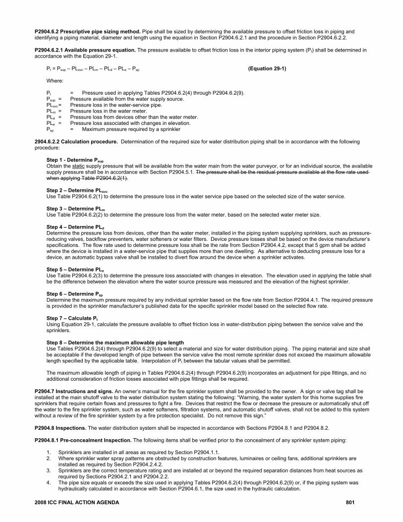
P2904.6.2 Prescriptive pipe sizing method. Pipe shall be sized by determining the available pressure to offset friction loss in piping and identifying a piping material, diameter and length using the equation in Section P2904.6.2.1 and the procedure in Section P2904.6.2.2.
P2904.6.2.1 Available pressure equation. The pressure available to offset friction loss in the interior piping system (Pt) shall be determined in accordance with the Equation 29-1.
Pt = Psup – PLsvc – PLm – PLd – PLe – Psp (Equation 29-1)
Where:
Pt = Pressure used in applying Tables P2904.6.2(4) through P2904.6.2(9). Psup = Pressure available from the water supply source. PLsvc = Pressure loss in the water-service pipe. PLm = Pressure loss in the water meter. PLd = Pressure loss from devices other than the water meter. PLe = Pressure loss associated with changes in elevation. Psp = Maximum pressure required by a sprinkler
2904.6.2.2 Calculation procedure. Determination of the required size for water distribution piping shall be in accordance with the following procedure:
Step 1 - Determine Psup Obtain the static supply pressure that will be available from the water main from the water purveyor, or for an individual source, the available supply pressure shall be in accordance with Section P2904.5.1. The pressure shall be the residual pressure available at the flow rate used when applying Table P2904.6.2(1).
Step 2 – Determine PLsvc Use Table P2904.6.2(1) to determine the pressure loss in the water service pipe based on the selected size of the water service.
Step 3 – Determine PLm Use Table P2904.6.2(2) to determine the pressure loss from the water meter. based on the selected water meter size.
Step 4 – Determine PLd Determine the pressure loss from devices, other than the water meter, installed in the piping system supplying sprinklers, such as pressure-reducing valves, backflow preventers, water softeners or water filters. Device pressure losses shall be based on the device manufacturer’s specifications. The flow rate used to determine pressure loss shall be the rate from Section P2904.4.2, except that 5 gpm shall be added where the device is installed in a water-service pipe that supplies more than one dwelling. As alternative to deducting pressure loss for a device, an automatic bypass valve shall be installed to divert flow around the device when a sprinkler activates.
Step 5 – Determine PLe Use Table P2904.6.2(3) to determine the pressure loss associated with changes in elevation. The elevation used in applying the table shall be the difference between the elevation where the water source pressure was measured and the elevation of the highest sprinkler.
Step 6 – Determine Psp Determine the maximum pressure required by any individual sprinkler based on the flow rate from Section P2904.4.1. The required pressure is provided in the sprinkler manufacturer’s published data for the specific sprinkler model based on the selected flow rate.
Step 7 – Calculate Pt Using Equation 29-1, calculate the pressure available to offset friction loss in water-distribution piping between the service valve and the sprinklers.
Step 8 – Determine the maximum allowable pipe length Use Tables P2904.6.2(4) through P2904.6.2(9) to select a material and size for water distribution piping. The piping material and size shall be acceptable if the developed length of pipe between the service valve the most remote sprinkler does not exceed the maximum allowable length specified by the applicable table. Interpolation of Pt between the tabular values shall be permitted.
The maximum allowable length of piping in Tables P2904.6.2(4) through P2904.6.2(9) incorporates an adjustment for pipe fittings, and no additional consideration of friction losses associated with pipe fittings shall be required.
P2904.7 Instructions and signs. An owner’s manual for the fire sprinkler system shall be provided to the owner. A sign or valve tag shall be installed at the main shutoff valve to the water distribution system stating the following: “Warning, the water system for this home supplies fire sprinklers that require certain flows and pressures to fight a fire. Devices that restrict the flow or decrease the pressure or automatically shut off the water to the fire sprinkler system, such as water softeners, filtration systems, and automatic shutoff valves, shall not be added to this system without a review of the fire sprinkler system by a fire protection specialist. Do not remove this sign.” P2904.8 Inspections. The water distribution system shall be inspected in accordance with Sections P2904.8.1 and P2904.8.2. P2904.8.1 Pre-concealment Inspection. The following items shall be verified prior to the concealment of any sprinkler system piping:
1. Sprinklers are installed in all areas as required by Section P2904.1.1. 2. Where sprinkler water spray patterns are obstructed by construction features, luminaires or ceiling fans, additional sprinklers are
installed as required by Section P2904.2.4.2. 3. Sprinklers are the correct temperature rating and are installed at or beyond the required separation distances from heat sources as
required by Sections P2904.2.1 and P2904.2.2. 4. The pipe size equals or exceeds the size used in applying Tables P2904.6.2(4) through P2904.6.2(9) or, if the piping system was
hydraulically calculated in accordance with Section P2904.6.1, the size used in the hydraulic calculation.
802 2008 ICC FINAL ACTION AGENDA
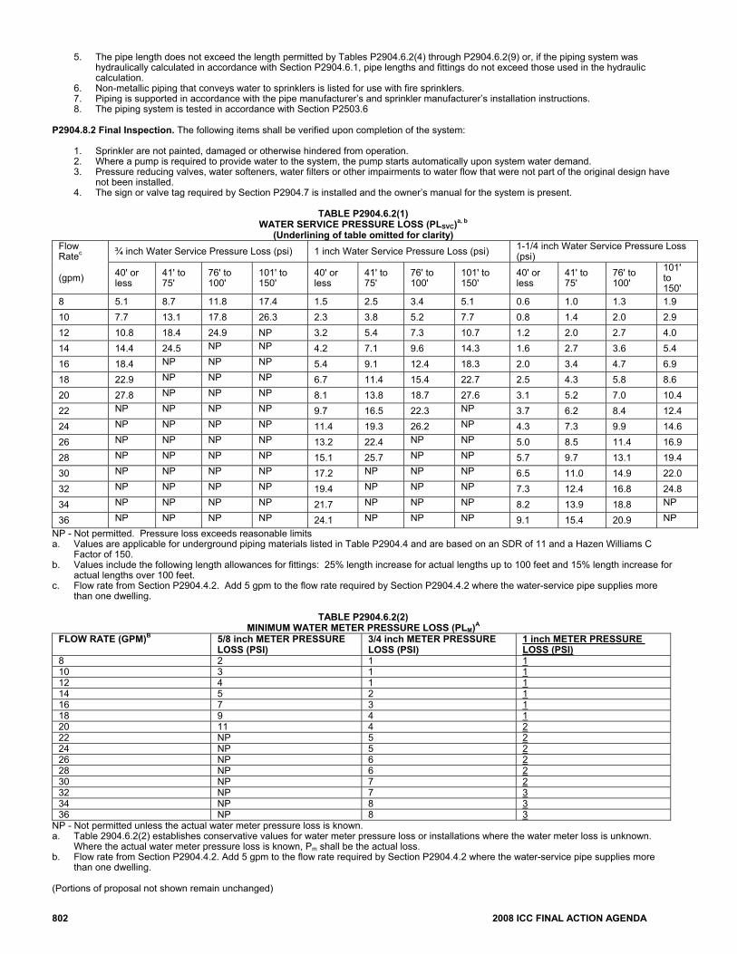
5. The pipe length does not exceed the length permitted by Tables P2904.6.2(4) through P2904.6.2(9) or, if the piping system was hydraulically calculated in accordance with Section P2904.6.1, pipe lengths and fittings do not exceed those used in the hydraulic calculation.
6. Non-metallic piping that conveys water to sprinklers is listed for use with fire sprinklers. 7. Piping is supported in accordance with the pipe manufacturer’s and sprinkler manufacturer’s installation instructions. 8. The piping system is tested in accordance with Section P2503.6
P2904.8.2 Final Inspection. The following items shall be verified upon completion of the system:
1. Sprinkler are not painted, damaged or otherwise hindered from operation. 2. Where a pump is required to provide water to the system, the pump starts automatically upon system water demand. 3. Pressure reducing valves, water softeners, water filters or other impairments to water flow that were not part of the original design have
not been installed. 4. The sign or valve tag required by Section P2904.7 is installed and the owner’s manual for the system is present.
TABLE P2904.6.2(1)
WATER SERVICE PRESSURE LOSS (PLSVC)a, b
(Underlining of table omitted for clarity) Flow Ratec ¾ inch Water Service Pressure Loss (psi) 1 inch Water Service Pressure Loss (psi) 1-1/4 inch Water Service Pressure Loss
(psi)
(gpm) 40' or less
41' to 75'
76' to 100'
101' to 150'
40' or less
41' to 75'
76' to 100'
101' to 150'
40' or less
41' to 75'
76' to 100'
101' to 150'
8 5.1 8.7 11.8 17.4 1.5 2.5 3.4 5.1 0.6 1.0 1.3 1.9 10 7.7 13.1 17.8 26.3 2.3 3.8 5.2 7.7 0.8 1.4 2.0 2.9 12 10.8 18.4 24.9 NP 3.2 5.4 7.3 10.7 1.2 2.0 2.7 4.0 14 14.4 24.5 NP NP 4.2 7.1 9.6 14.3 1.6 2.7 3.6 5.4 16 18.4 NP NP NP 5.4 9.1 12.4 18.3 2.0 3.4 4.7 6.9 18 22.9 NP NP NP 6.7 11.4 15.4 22.7 2.5 4.3 5.8 8.6 20 27.8 NP NP NP 8.1 13.8 18.7 27.6 3.1 5.2 7.0 10.4 22 NP NP NP NP 9.7 16.5 22.3 NP 3.7 6.2 8.4 12.4 24 NP NP NP NP 11.4 19.3 26.2 NP 4.3 7.3 9.9 14.6 26 NP NP NP NP 13.2 22.4 NP NP 5.0 8.5 11.4 16.9 28 NP NP NP NP 15.1 25.7 NP NP 5.7 9.7 13.1 19.4 30 NP NP NP NP 17.2 NP NP NP 6.5 11.0 14.9 22.0 32 NP NP NP NP 19.4 NP NP NP 7.3 12.4 16.8 24.8 34 NP NP NP NP 21.7 NP NP NP 8.2 13.9 18.8 NP
36 NP NP NP NP 24.1 NP NP NP 9.1 15.4 20.9 NP NP - Not permitted. Pressure loss exceeds reasonable limits a. Values are applicable for underground piping materials listed in Table P2904.4 and are based on an SDR of 11 and a Hazen Williams C
Factor of 150. b. Values include the following length allowances for fittings: 25% length increase for actual lengths up to 100 feet and 15% length increase for
actual lengths over 100 feet. c. Flow rate from Section P2904.4.2. Add 5 gpm to the flow rate required by Section P2904.4.2 where the water-service pipe supplies more
than one dwelling.
TABLE P2904.6.2(2) MINIMUM WATER METER PRESSURE LOSS (PLM)A
FLOW RATE (GPM)B 5/8 inch METER PRESSURE LOSS (PSI)
3/4 inch METER PRESSURE LOSS (PSI)
1 inch METER PRESSURE LOSS (PSI)
8 2 1 1 10 3 1 1 12 4 1 1 14 5 2 1 16 7 3 1 18 9 4 1 20 11 4 2 22 NP 5 2 24 NP 5 2 26 NP 6 2 28 NP 6 2 30 NP 7 2 32 NP 7 3 34 NP 8 3 36 NP 8 3
NP - Not permitted unless the actual water meter pressure loss is known. a. Table 2904.6.2(2) establishes conservative values for water meter pressure loss or installations where the water meter loss is unknown.
Where the actual water meter pressure loss is known, Pm shall be the actual loss. b. Flow rate from Section P2904.4.2. Add 5 gpm to the flow rate required by Section P2904.4.2 where the water-service pipe supplies more
than one dwelling. (Portions of proposal not shown remain unchanged)
2008 ICC FINAL ACTION AGENDA 803
Committee Reason: This proposal provides an easy, cost effective method for the installation of fire sprinklers in residential applications. Section P2904.1 modifications clarify; 1) that the intent of the section is to address residential sprinkler systems for dwelling units, 2) that Section P2904 applies to both multipurpose and stand- alone systems except those using antifreeze and dry piping and 3) that backflow protection is not required between a stand-alone system and the water distribution system. Section P2404.2 modification clarifies that sprinklers must be new and not used or refurbished. Section P2904.2.5 modification clarifies that the concern for checking for excess cement only applies to the threaded adapter fittings and not to every fitting in the system. Section P2904.3 modification clarifies that the hanger requirements for sprinkler piping will be those required by the code for cold water distribution piping. Section P2904.3.4 modification adds the requirement for having a sprinkler system drain valve. Section P2901.5.2 modification clarifies that the 7 minute water supply capacity only applies to buildings one story in height having less than 2000 square feet and that the 10 minute water supply capacity is for buildings of 2 or more stories in height or equal to and greater than 2000 square feet. Section P2904.6.2.2 modification clarifies that the supply pressure measurement is a static pressure (not a fire flow pressure). Table P2904.6.2(2) modification adds a 1 inch water meter pressure loss column because some water departments are providing one inch meters for residential buildings with fire sprinkler systems. Assembly Action: None Individual Consideration Agenda This item is on the agenda for individual consideration because a public comment was submitted. Public Comment: Ronny J. Coleman, Retired California State Fire Marshal, representing IRC Fire Sprinkler Coalition, requests Approval as Modified by this public comment. Modify proposal as follows: P2904.1 General. Where installed, The design and installation of residential fire sprinkler systems, or portions thereof, shall be in accordance with NFPA 13D or Section P2904, which shall be considered equivalent to NFPA 13D. Partial residential sprinkler systems shall be permitted to be installed in buildings not required to be equipped with a residential sprinkler system. Section P2904 shall apply to stand-alone and multipurpose wet-pipe sprinkler systems that do not include the use of antifreeze. A multipurpose fire sprinkler system shall provide domestic water to both fire sprinklers and plumbing fixtures. A stand-alone sprinkler system shall be separate and independent from the water distribution system. A backflow flow preventer shall not be required to separate a stand-alone sprinkler system from the water distribution system. (Portions of proposal not shown remain unchanged) Commenter=s Reason: The Coalition acknowledges that the Committee voted to approve this code change to include the design and installation requirements in the body of the IRC for residential sprinkler systems. The Coalition is submitting this public comment in an effort to clarify the floor modifications made at the Palm Springs hearing. The revised first sentence clarifies that this section regulates the design and installation of residential sprinklers and does not, in any way, mandate residential sprinkler systems. The added second sentence emphasizes that it is permissible to install a partial system when residential sprinklers are not required. This allows P2904 to stand on its own, whether sprinklers are required or not. Final Action: AS AM AMPC D
RP8-07/08 Appendix P Proposed Change as Submitted: Proponent: Steven Orlowski, National Association of Home Builders Revise as follows:
APPENDIX P SPRINKLERS
AP101 (Supp) Fire sprinklers. An approved automatic fire sprinkler system shall be installed in new buildings and structures one-and two-family dwellings and townhouses in accordance with NFPA 13D.
FIRE SPRINKLER SYSTEMS
SECTION AP101 GENERAL
AP101.1 Scope. The provisions of this appendix shall control the design and installation of automatic fire sprinkler system in new one- and two-family dwellings and townhouses.
804 2008 ICC FINAL ACTION AGENDA
Exception: Residential fire sprinklers installed in accordance with NFPA 13D shall be permitted.
SECTION AP102 REQUIREMENTS FOR SPRINKLERS
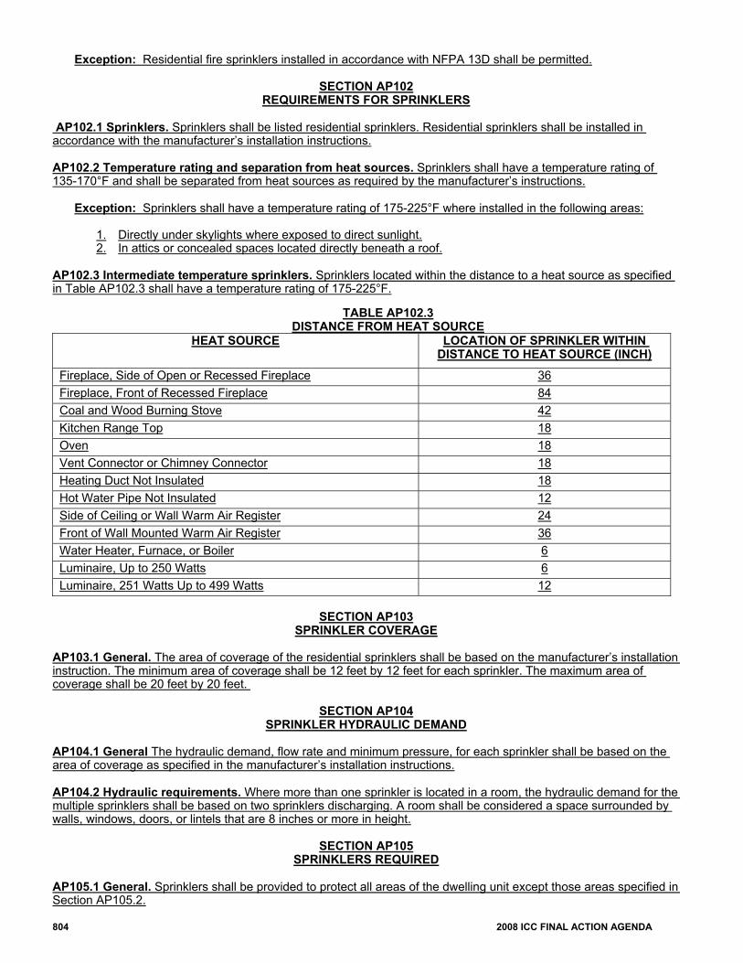
AP102.1 Sprinklers. Sprinklers shall be listed residential sprinklers. Residential sprinklers shall be installed in accordance with the manufacturer’s installation instructions. AP102.2 Temperature rating and separation from heat sources. Sprinklers shall have a temperature rating of 135-170°F and shall be separated from heat sources as required by the manufacturer’s instructions. Exception: Sprinklers shall have a temperature rating of 175-225°F where installed in the following areas: 1. Directly under skylights where exposed to direct sunlight. 2. In attics or concealed spaces located directly beneath a roof. AP102.3 Intermediate temperature sprinklers. Sprinklers located within the distance to a heat source as specified in Table AP102.3 shall have a temperature rating of 175-225°F.
TABLE AP102.3 DISTANCE FROM HEAT SOURCE
HEAT SOURCE LOCATION OF SPRINKLER WITHIN DISTANCE TO HEAT SOURCE (INCH)
Fireplace, Side of Open or Recessed Fireplace 36 Fireplace, Front of Recessed Fireplace 84 Coal and Wood Burning Stove 42 Kitchen Range Top 18 Oven 18 Vent Connector or Chimney Connector 18 Heating Duct Not Insulated 18 Hot Water Pipe Not Insulated 12 Side of Ceiling or Wall Warm Air Register 24 Front of Wall Mounted Warm Air Register 36 Water Heater, Furnace, or Boiler 6 Luminaire, Up to 250 Watts 6 Luminaire, 251 Watts Up to 499 Watts 12
SECTION AP103
SPRINKLER COVERAGE AP103.1 General. The area of coverage of the residential sprinklers shall be based on the manufacturer’s installation instruction. The minimum area of coverage shall be 12 feet by 12 feet for each sprinkler. The maximum area of coverage shall be 20 feet by 20 feet.
SECTION AP104 SPRINKLER HYDRAULIC DEMAND
AP104.1 General The hydraulic demand, flow rate and minimum pressure, for each sprinkler shall be based on the area of coverage as specified in the manufacturer’s installation instructions. AP104.2 Hydraulic requirements. Where more than one sprinkler is located in a room, the hydraulic demand for the multiple sprinklers shall be based on two sprinklers discharging. A room shall be considered a space surrounded by walls, windows, doors, or lintels that are 8 inches or more in height.
SECTION AP105
SPRINKLERS REQUIRED AP105.1 General. Sprinklers shall be provided to protect all areas of the dwelling unit except those areas specified in Section AP105.2.
2008 ICC FINAL ACTION AGENDA 805
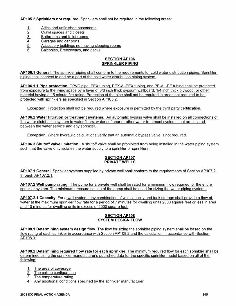
AP105.2 Sprinklers not required. Sprinklers shall not be required in the following areas: 1. Attics and unfinished basements 2. Crawl spaces and closets 3. Bathrooms and toilet rooms 4. Garages and car ports 5. Accessory buildings not having sleeping rooms 6. Balconies, Breezeways, and decks
SECTION AP106 SPRINKLER PIPING
AP106.1 General. The sprinkler piping shall conform to the requirements for cold water distribution piping. Sprinkler piping shall connect to and be a part of the cold water distribution piping system. AP106.1.1 Pipe protection. CPVC pipe, PEX tubing, PEX-Al-PEX tubing, and PE-AL-PE tubing shall be protected from exposure to the living space by a layer of 3/8 inch thick gypsum wallboard, 1/4 inch thick plywood, or other material having a 15 minute fire rating. Protection of the pipe shall not be required in areas not required to be protected with sprinklers as specified in Section AP105.2. Exception. Protection shall not be required where exposure is permitted by the third party certification. AP106.2 Water filtration or treatment systems. An automatic bypass valve shall be installed on all connections of the water distribution system to water filters, water softener or other water treatment systems that are located between the water service and any sprinkler. Exception. Where hydraulic calculations verify that an automatic bypass valve is not required. AP106.3 Shutoff valve limitation. A shutoff valve shall be prohibited from being installed in the water piping system such that the valve only isolates the water supply to a sprinkler or sprinklers.
SECTION AP107 PRIVATE WELLS
AP107.1 General. Sprinkler systems supplied by private well shall conform to the requirements of Section AP107.2 through AP107.2.1. AP107.2 Well pump rating. The pump for a private well shall be rated for a minimum flow required for the entire sprinkler system. The minimum pressure setting of the pump shall be used for sizing the water piping system. AP107.2.1 Capacity. For a well system, any combination of well capacity and tank storage shall provide a flow of water at the maximum sprinkler flow rate for a period of 7 minutes for dwelling units 2000 square feet or less in area and 10 minutes for dwelling units in excess of 2000 square feet.
SECTION AP108
SYSTEM DESIGN FLOW AP108.1 Determining system design flow. The flow for sizing the sprinkler piping system shall be based on the flow rating of each sprinkler in accordance with Section AP108.2 and the calculation in accordance with Section AP108.3. AP108.2 Determining required flow rate for each sprinkler. The minimum required flow for each sprinkler shall be determined using the sprinkler manufacturer’s published data for the specific sprinkler model based on all of the following: 1. The area of coverage 2. The ceiling configuration 3. The temperature rating 4. Any additional conditions specified by the sprinkler manufacturer.
806 2008 ICC FINAL ACTION AGENDA
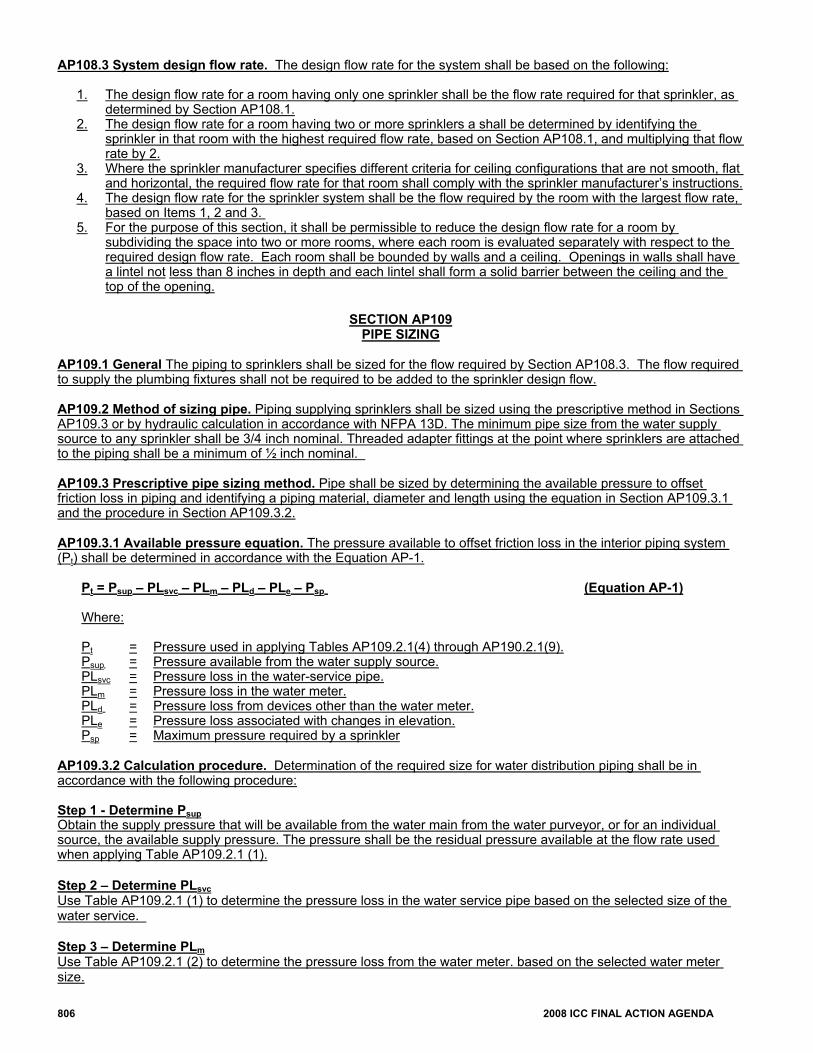
AP108.3 System design flow rate. The design flow rate for the system shall be based on the following:
1. The design flow rate for a room having only one sprinkler shall be the flow rate required for that sprinkler, as determined by Section AP108.1.
2. The design flow rate for a room having two or more sprinklers a shall be determined by identifying the sprinkler in that room with the highest required flow rate, based on Section AP108.1, and multiplying that flow rate by 2.
3. Where the sprinkler manufacturer specifies different criteria for ceiling configurations that are not smooth, flat and horizontal, the required flow rate for that room shall comply with the sprinkler manufacturer’s instructions.
4. The design flow rate for the sprinkler system shall be the flow required by the room with the largest flow rate, based on Items 1, 2 and 3.
5. For the purpose of this section, it shall be permissible to reduce the design flow rate for a room by subdividing the space into two or more rooms, where each room is evaluated separately with respect to the required design flow rate. Each room shall be bounded by walls and a ceiling. Openings in walls shall have a lintel not less than 8 inches in depth and each lintel shall form a solid barrier between the ceiling and the top of the opening.
SECTION AP109
PIPE SIZING AP109.1 General The piping to sprinklers shall be sized for the flow required by Section AP108.3. The flow required to supply the plumbing fixtures shall not be required to be added to the sprinkler design flow. AP109.2 Method of sizing pipe. Piping supplying sprinklers shall be sized using the prescriptive method in Sections AP109.3 or by hydraulic calculation in accordance with NFPA 13D. The minimum pipe size from the water supply source to any sprinkler shall be 3/4 inch nominal. Threaded adapter fittings at the point where sprinklers are attached to the piping shall be a minimum of ½ inch nominal.
AP109.3 Prescriptive pipe sizing method. Pipe shall be sized by determining the available pressure to offset friction loss in piping and identifying a piping material, diameter and length using the equation in Section AP109.3.1 and the procedure in Section AP109.3.2. AP109.3.1 Available pressure equation. The pressure available to offset friction loss in the interior piping system (Pt) shall be determined in accordance with the Equation AP-1.
Pt = Psup – PLsvc – PLm – PLd – PLe – Psp (Equation AP-1)
Where: Pt = Pressure used in applying Tables AP109.2.1(4) through AP190.2.1(9). Psup = Pressure available from the water supply source. PLsvc = Pressure loss in the water-service pipe. PLm = Pressure loss in the water meter. PLd = Pressure loss from devices other than the water meter. PLe = Pressure loss associated with changes in elevation. Psp = Maximum pressure required by a sprinkler
AP109.3.2 Calculation procedure. Determination of the required size for water distribution piping shall be in accordance with the following procedure: Step 1 - Determine Psup Obtain the supply pressure that will be available from the water main from the water purveyor, or for an individual source, the available supply pressure. The pressure shall be the residual pressure available at the flow rate used when applying Table AP109.2.1 (1). Step 2 – Determine PLsvc Use Table AP109.2.1 (1) to determine the pressure loss in the water service pipe based on the selected size of the water service. Step 3 – Determine PLm Use Table AP109.2.1 (2) to determine the pressure loss from the water meter. based on the selected water meter size.
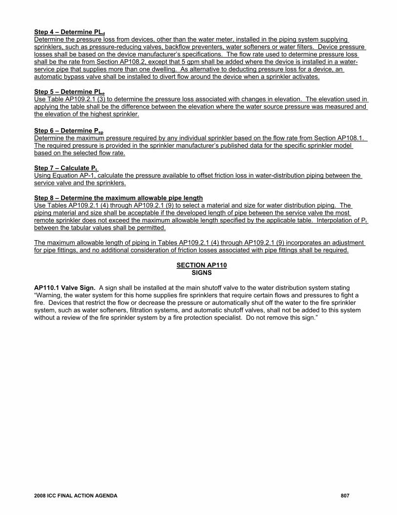
2008 ICC FINAL ACTION AGENDA 807
Step 4 – Determine PLd Determine the pressure loss from devices, other than the water meter, installed in the piping system supplying sprinklers, such as pressure-reducing valves, backflow preventers, water softeners or water filters. Device pressure losses shall be based on the device manufacturer’s specifications. The flow rate used to determine pressure loss shall be the rate from Section AP108.2, except that 5 gpm shall be added where the device is installed in a water-service pipe that supplies more than one dwelling. As alternative to deducting pressure loss for a device, an automatic bypass valve shall be installed to divert flow around the device when a sprinkler activates. Step 5 – Determine PLe Use Table AP109.2.1 (3) to determine the pressure loss associated with changes in elevation. The elevation used in applying the table shall be the difference between the elevation where the water source pressure was measured and the elevation of the highest sprinkler. Step 6 – Determine Psp Determine the maximum pressure required by any individual sprinkler based on the flow rate from Section AP108.1. The required pressure is provided in the sprinkler manufacturer’s published data for the specific sprinkler model based on the selected flow rate. Step 7 – Calculate Pt Using Equation AP-1, calculate the pressure available to offset friction loss in water-distribution piping between the service valve and the sprinklers. Step 8 – Determine the maximum allowable pipe length Use Tables AP109.2.1 (4) through AP109.2.1 (9) to select a material and size for water distribution piping. The piping material and size shall be acceptable if the developed length of pipe between the service valve the most remote sprinkler does not exceed the maximum allowable length specified by the applicable table. Interpolation of Pt between the tabular values shall be permitted. The maximum allowable length of piping in Tables AP109.2.1 (4) through AP109.2.1 (9) incorporates an adjustment for pipe fittings, and no additional consideration of friction losses associated with pipe fittings shall be required.
SECTION AP110
SIGNS AP110.1 Valve Sign. A sign shall be installed at the main shutoff valve to the water distribution system stating “Warning, the water system for this home supplies fire sprinklers that require certain flows and pressures to fight a fire. Devices that restrict the flow or decrease the pressure or automatically shut off the water to the fire sprinkler system, such as water softeners, filtration systems, and automatic shutoff valves, shall not be added to this system without a review of the fire sprinkler system by a fire protection specialist. Do not remove this sign.”
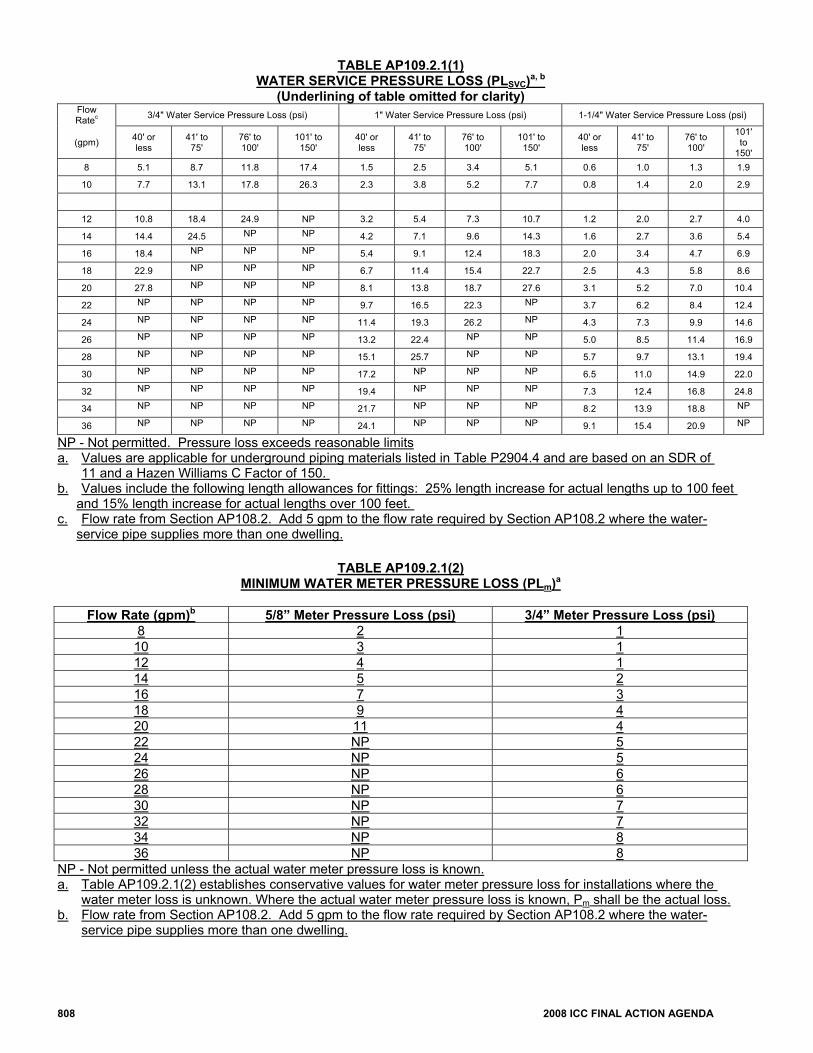
808 2008 ICC FINAL ACTION AGENDA
TABLE AP109.2.1(1) WATER SERVICE PRESSURE LOSS (PLSVC)a, b
(Underlining of table omitted for clarity) Flow Ratec 3/4" Water Service Pressure Loss (psi) 1" Water Service Pressure Loss (psi) 1-1/4" Water Service Pressure Loss (psi)
(gpm) 40' or less
41' to 75'
76' to 100'
101' to 150'
40' or less
41' to 75'
76' to 100'
101' to 150'
40' or less
41' to 75'
76' to 100'
101' to
150' 8 5.1 8.7 11.8 17.4 1.5 2.5 3.4 5.1 0.6 1.0 1.3 1.9
10 7.7 13.1 17.8 26.3 2.3 3.8 5.2 7.7 0.8 1.4 2.0 2.9
12 10.8 18.4 24.9 NP 3.2 5.4 7.3 10.7 1.2 2.0 2.7 4.0
14 14.4 24.5 NP NP 4.2 7.1 9.6 14.3 1.6 2.7 3.6 5.4
16 18.4 NP NP NP 5.4 9.1 12.4 18.3 2.0 3.4 4.7 6.9
18 22.9 NP NP NP 6.7 11.4 15.4 22.7 2.5 4.3 5.8 8.6
20 27.8 NP NP NP 8.1 13.8 18.7 27.6 3.1 5.2 7.0 10.4
22 NP NP NP NP 9.7 16.5 22.3 NP 3.7 6.2 8.4 12.4
24 NP NP NP NP 11.4 19.3 26.2 NP 4.3 7.3 9.9 14.6
26 NP NP NP NP 13.2 22.4 NP NP 5.0 8.5 11.4 16.9
28 NP NP NP NP 15.1 25.7 NP NP 5.7 9.7 13.1 19.4
30 NP NP NP NP 17.2 NP NP NP 6.5 11.0 14.9 22.0
32 NP NP NP NP 19.4 NP NP NP 7.3 12.4 16.8 24.8
34 NP NP NP NP 21.7 NP NP NP 8.2 13.9 18.8 NP
36 NP NP NP NP 24.1 NP NP NP 9.1 15.4 20.9 NP
NP - Not permitted. Pressure loss exceeds reasonable limits a. Values are applicable for underground piping materials listed in Table P2904.4 and are based on an SDR of 11 and a Hazen Williams C Factor of 150. b. Values include the following length allowances for fittings: 25% length increase for actual lengths up to 100 feet
and 15% length increase for actual lengths over 100 feet. c. Flow rate from Section AP108.2. Add 5 gpm to the flow rate required by Section AP108.2 where the water-
service pipe supplies more than one dwelling.
TABLE AP109.2.1(2) MINIMUM WATER METER PRESSURE LOSS (PLm)a
Flow Rate (gpm)b 5/8” Meter Pressure Loss (psi) 3/4” Meter Pressure Loss (psi)
8 2 1 10 3 1 12 4 1 14 5 2 16 7 3 18 9 4 20 11 4 22 NP 5 24 NP 5 26 NP 6 28 NP 6 30 NP 7 32 NP 7 34 NP 8 36 NP 8
NP - Not permitted unless the actual water meter pressure loss is known. a. Table AP109.2.1(2) establishes conservative values for water meter pressure loss for installations where the
water meter loss is unknown. Where the actual water meter pressure loss is known, Pm shall be the actual loss. b. Flow rate from Section AP108.2. Add 5 gpm to the flow rate required by Section AP108.2 where the water-
service pipe supplies more than one dwelling.
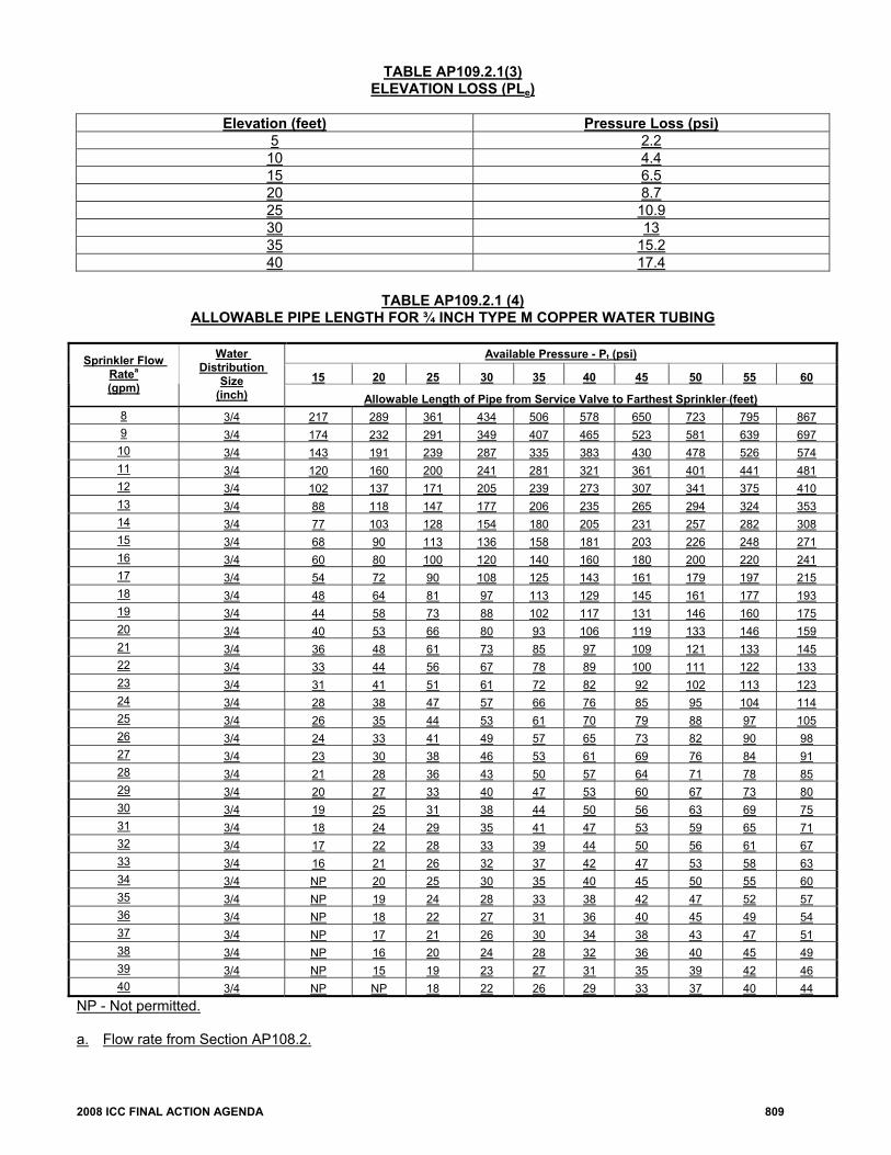
2008 ICC FINAL ACTION AGENDA 809
TABLE AP109.2.1(3) ELEVATION LOSS (PLe)
Elevation (feet) Pressure Loss (psi)
5 2.2 10 4.4 15 6.5 20 8.7 25 10.9 30 13 35 15.2 40 17.4
TABLE AP109.2.1 (4)
ALLOWABLE PIPE LENGTH FOR ¾ INCH TYPE M COPPER WATER TUBING
Available Pressure - Pt (psi)
15 20 25 30 35 40 45 50 55 60 Sprinkler Flow
Ratea (gpm)
Water Distribution
Size (inch) Allowable Length of Pipe from Service Valve to Farthest Sprinkler (feet)
8 3/4 217 289 361 434 506 578 650 723 795 867 9 3/4 174 232 291 349 407 465 523 581 639 697
10 3/4 143 191 239 287 335 383 430 478 526 574 11 3/4 120 160 200 241 281 321 361 401 441 481 12 3/4 102 137 171 205 239 273 307 341 375 410 13 3/4 88 118 147 177 206 235 265 294 324 353 14 3/4 77 103 128 154 180 205 231 257 282 308 15 3/4 68 90 113 136 158 181 203 226 248 271 16 3/4 60 80 100 120 140 160 180 200 220 241 17 3/4 54 72 90 108 125 143 161 179 197 215 18 3/4 48 64 81 97 113 129 145 161 177 193 19 3/4 44 58 73 88 102 117 131 146 160 175 20 3/4 40 53 66 80 93 106 119 133 146 159 21 3/4 36 48 61 73 85 97 109 121 133 145 22 3/4 33 44 56 67 78 89 100 111 122 133 23 3/4 31 41 51 61 72 82 92 102 113 123 24 3/4 28 38 47 57 66 76 85 95 104 114 25 3/4 26 35 44 53 61 70 79 88 97 105 26 3/4 24 33 41 49 57 65 73 82 90 98 27 3/4 23 30 38 46 53 61 69 76 84 91 28 3/4 21 28 36 43 50 57 64 71 78 85 29 3/4 20 27 33 40 47 53 60 67 73 80 30 3/4 19 25 31 38 44 50 56 63 69 75 31 3/4 18 24 29 35 41 47 53 59 65 71 32 3/4 17 22 28 33 39 44 50 56 61 67 33 3/4 16 21 26 32 37 42 47 53 58 63 34 3/4 NP 20 25 30 35 40 45 50 55 60 35 3/4 NP 19 24 28 33 38 42 47 52 57 36 3/4 NP 18 22 27 31 36 40 45 49 54 37 3/4 NP 17 21 26 30 34 38 43 47 51 38 3/4 NP 16 20 24 28 32 36 40 45 49 39 3/4 NP 15 19 23 27 31 35 39 42 46 40 3/4 NP NP 18 22 26 29 33 37 40 44
NP - Not permitted. a. Flow rate from Section AP108.2.
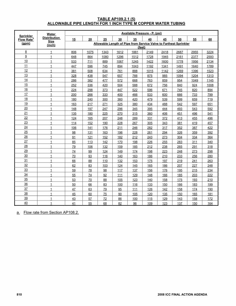
810 2008 ICC FINAL ACTION AGENDA
TABLE AP109.2.1 (5) ALLOWABLE PIPE LENGTH FOR 1 INCH TYPE M COPPER WATER TUBING
Available Pressure - Pt (psi)
15 20 25 30 35 40 45 50 55 60 Sprinkler
Flow Ratea (gpm)
Water Distribution
Size (inch) Allowable Length of Pipe from Service Valve to Farthest Sprinkler
(feet) 8 1 806 1075 1343 1612 1881 2149 2418 2687 2955 3224 9 1 648 864 1080 1296 1512 1728 1945 2161 2377 2593
10 1 533 711 889 1067 1245 1422 1600 1778 1956 2134 11 1 447 596 745 894 1043 1192 1341 1491 1640 1789 12 1 381 508 634 761 888 1015 1142 1269 1396 1523 13 1 328 438 547 657 766 875 985 1094 1204 1313 14 1 286 382 477 572 668 763 859 954 1049 1145 15 1 252 336 420 504 588 672 756 840 924 1008 16 1 224 298 373 447 522 596 671 745 820 894 17 1 200 266 333 400 466 533 600 666 733 799 18 1 180 240 300 360 420 479 539 599 659 719 19 1 163 217 271 325 380 434 488 542 597 651 20 1 148 197 247 296 345 395 444 493 543 592 21 1 135 180 225 270 315 360 406 451 496 541 22 1 124 165 207 248 289 331 372 413 455 496 23 1 114 152 190 228 267 305 343 381 419 457 24 1 106 141 176 211 246 282 317 352 387 422 25 1 98 131 163 196 228 261 294 326 359 392 26 1 91 121 152 182 212 243 273 304 334 364 27 1 85 113 142 170 198 226 255 283 311 340 28 1 79 106 132 159 185 212 238 265 291 318 29 1 74 99 124 149 174 198 223 248 273 298 30 1 70 93 116 140 163 186 210 233 256 280 31 1 66 88 110 132 153 175 197 219 241 263 32 1 62 83 103 124 145 165 186 207 227 248 33 1 59 78 98 117 137 156 176 195 215 234 34 1 55 74 92 111 129 148 166 185 203 222 35 1 53 70 88 105 123 140 158 175 193 210 36 1 50 66 83 100 116 133 150 166 183 199 37 1 47 63 79 95 111 126 142 158 174 190 38 1 45 60 75 90 105 120 135 150 165 181 39 1 43 57 72 86 100 115 129 143 158 172 40 1 41 55 68 82 96 109 123 137 150 164
a. Flow rate from Section AP108.2.
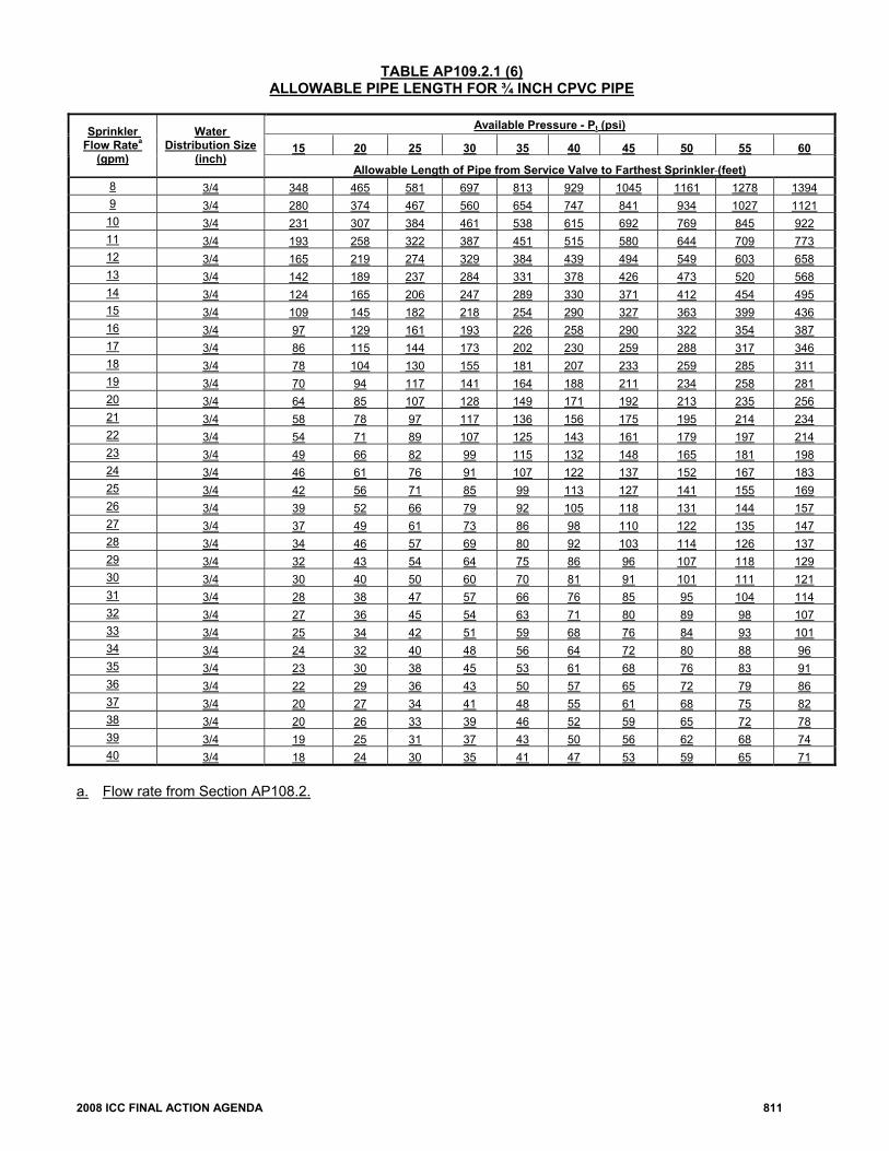
2008 ICC FINAL ACTION AGENDA 811
TABLE AP109.2.1 (6) ALLOWABLE PIPE LENGTH FOR ¾ INCH CPVC PIPE
Available Pressure - Pt (psi)
15 20 25 30 35 40 45 50 55 60 Sprinkler
Flow Ratea (gpm)
Water Distribution Size
(inch) Allowable Length of Pipe from Service Valve to Farthest Sprinkler (feet)
8 3/4 348 465 581 697 813 929 1045 1161 1278 1394 9 3/4 280 374 467 560 654 747 841 934 1027 1121
10 3/4 231 307 384 461 538 615 692 769 845 922 11 3/4 193 258 322 387 451 515 580 644 709 773 12 3/4 165 219 274 329 384 439 494 549 603 658 13 3/4 142 189 237 284 331 378 426 473 520 568 14 3/4 124 165 206 247 289 330 371 412 454 495 15 3/4 109 145 182 218 254 290 327 363 399 436 16 3/4 97 129 161 193 226 258 290 322 354 387 17 3/4 86 115 144 173 202 230 259 288 317 346 18 3/4 78 104 130 155 181 207 233 259 285 311 19 3/4 70 94 117 141 164 188 211 234 258 281 20 3/4 64 85 107 128 149 171 192 213 235 256 21 3/4 58 78 97 117 136 156 175 195 214 234 22 3/4 54 71 89 107 125 143 161 179 197 214 23 3/4 49 66 82 99 115 132 148 165 181 198 24 3/4 46 61 76 91 107 122 137 152 167 183 25 3/4 42 56 71 85 99 113 127 141 155 169 26 3/4 39 52 66 79 92 105 118 131 144 157 27 3/4 37 49 61 73 86 98 110 122 135 147 28 3/4 34 46 57 69 80 92 103 114 126 137 29 3/4 32 43 54 64 75 86 96 107 118 129 30 3/4 30 40 50 60 70 81 91 101 111 121 31 3/4 28 38 47 57 66 76 85 95 104 114 32 3/4 27 36 45 54 63 71 80 89 98 107 33 3/4 25 34 42 51 59 68 76 84 93 101 34 3/4 24 32 40 48 56 64 72 80 88 96 35 3/4 23 30 38 45 53 61 68 76 83 91 36 3/4 22 29 36 43 50 57 65 72 79 86 37 3/4 20 27 34 41 48 55 61 68 75 82 38 3/4 20 26 33 39 46 52 59 65 72 78 39 3/4 19 25 31 37 43 50 56 62 68 74 40 3/4 18 24 30 35 41 47 53 59 65 71
a. Flow rate from Section AP108.2.
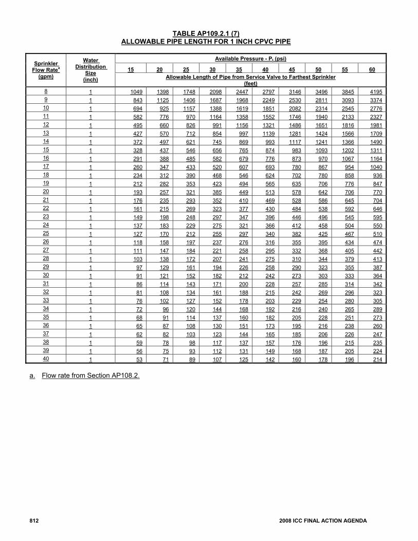
812 2008 ICC FINAL ACTION AGENDA
TABLE AP109.2.1 (7) ALLOWABLE PIPE LENGTH FOR 1 INCH CPVC PIPE
Available Pressure - Pt (psi)
15 20 25 30 35 40 45 50 55 60 Sprinkler
Flow Ratea (gpm)
Water Distribution
Size (inch) Allowable Length of Pipe from Service Valve to Farthest Sprinkler
(feet) 8 1 1049 1398 1748 2098 2447 2797 3146 3496 3845 4195 9 1 843 1125 1406 1687 1968 2249 2530 2811 3093 3374
10 1 694 925 1157 1388 1619 1851 2082 2314 2545 2776 11 1 582 776 970 1164 1358 1552 1746 1940 2133 2327 12 1 495 660 826 991 1156 1321 1486 1651 1816 1981 13 1 427 570 712 854 997 1139 1281 1424 1566 1709 14 1 372 497 621 745 869 993 1117 1241 1366 1490 15 1 328 437 546 656 765 874 983 1093 1202 1311 16 1 291 388 485 582 679 776 873 970 1067 1164 17 1 260 347 433 520 607 693 780 867 954 1040 18 1 234 312 390 468 546 624 702 780 858 936 19 1 212 282 353 423 494 565 635 706 776 847 20 1 193 257 321 385 449 513 578 642 706 770 21 1 176 235 293 352 410 469 528 586 645 704 22 1 161 215 269 323 377 430 484 538 592 646 23 1 149 198 248 297 347 396 446 496 545 595 24 1 137 183 229 275 321 366 412 458 504 550 25 1 127 170 212 255 297 340 382 425 467 510 26 1 118 158 197 237 276 316 355 395 434 474 27 1 111 147 184 221 258 295 332 368 405 442 28 1 103 138 172 207 241 275 310 344 379 413 29 1 97 129 161 194 226 258 290 323 355 387 30 1 91 121 152 182 212 242 273 303 333 364 31 1 86 114 143 171 200 228 257 285 314 342 32 1 81 108 134 161 188 215 242 269 296 323 33 1 76 102 127 152 178 203 229 254 280 305 34 1 72 96 120 144 168 192 216 240 265 289 35 1 68 91 114 137 160 182 205 228 251 273 36 1 65 87 108 130 151 173 195 216 238 260 37 1 62 82 103 123 144 165 185 206 226 247 38 1 59 78 98 117 137 157 176 196 215 235 39 1 56 75 93 112 131 149 168 187 205 224 40 1 53 71 89 107 125 142 160 178 196 214
a. Flow rate from Section AP108.2.
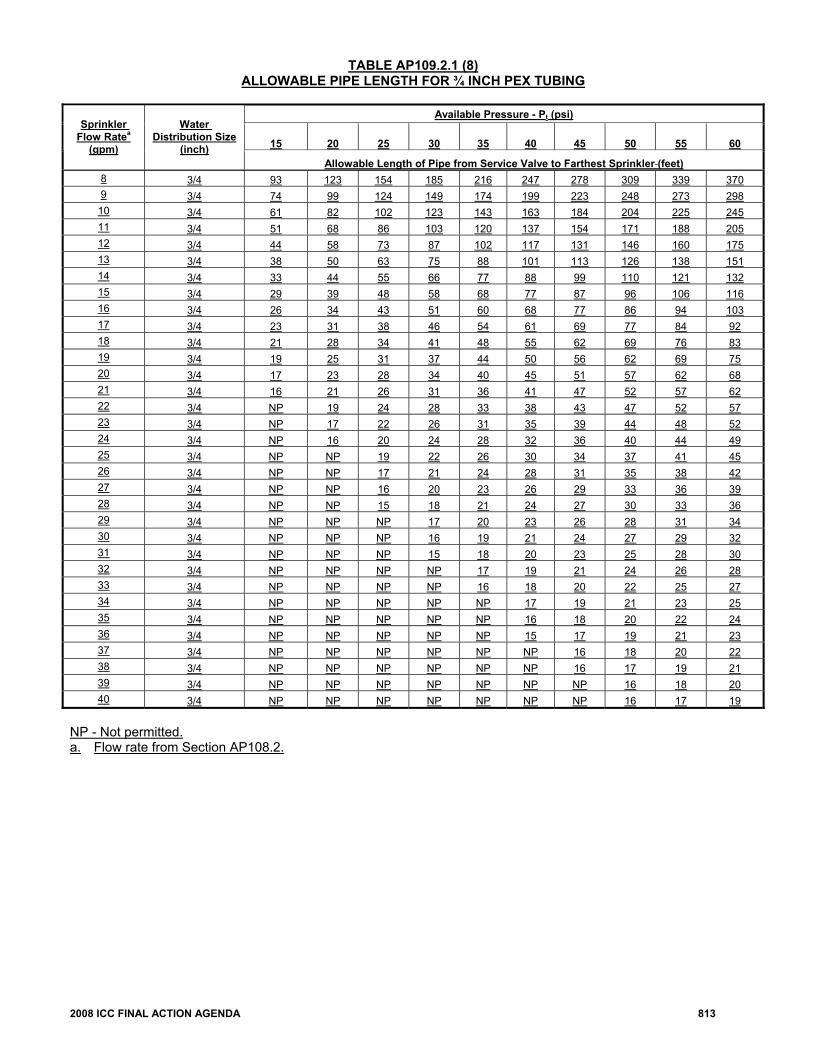
2008 ICC FINAL ACTION AGENDA 813
TABLE AP109.2.1 (8) ALLOWABLE PIPE LENGTH FOR ¾ INCH PEX TUBING
Available Pressure - Pt (psi)
15
20 25 30 35 40 45 50 55 60
Sprinkler Flow Ratea
(gpm)
Water Distribution Size
(inch) Allowable Length of Pipe from Service Valve to Farthest Sprinkler (feet)
8 3/4 93 123 154 185 216 247 278 309 339 370 9 3/4 74 99 124 149 174 199 223 248 273 298
10 3/4 61 82 102 123 143 163 184 204 225 245 11 3/4 51 68 86 103 120 137 154 171 188 205 12 3/4 44 58 73 87 102 117 131 146 160 175 13 3/4 38 50 63 75 88 101 113 126 138 151 14 3/4 33 44 55 66 77 88 99 110 121 132 15 3/4 29 39 48 58 68 77 87 96 106 116 16 3/4 26 34 43 51 60 68 77 86 94 103 17 3/4 23 31 38 46 54 61 69 77 84 92 18 3/4 21 28 34 41 48 55 62 69 76 83 19 3/4 19 25 31 37 44 50 56 62 69 75 20 3/4 17 23 28 34 40 45 51 57 62 68 21 3/4 16 21 26 31 36 41 47 52 57 62 22 3/4 NP 19 24 28 33 38 43 47 52 57 23 3/4 NP 17 22 26 31 35 39 44 48 52 24 3/4 NP 16 20 24 28 32 36 40 44 49 25 3/4 NP NP 19 22 26 30 34 37 41 45 26 3/4 NP NP 17 21 24 28 31 35 38 42 27 3/4 NP NP 16 20 23 26 29 33 36 39 28 3/4 NP NP 15 18 21 24 27 30 33 36 29 3/4 NP NP NP 17 20 23 26 28 31 34 30 3/4 NP NP NP 16 19 21 24 27 29 32 31 3/4 NP NP NP 15 18 20 23 25 28 30 32 3/4 NP NP NP NP 17 19 21 24 26 28 33 3/4 NP NP NP NP 16 18 20 22 25 27 34 3/4 NP NP NP NP NP 17 19 21 23 25 35 3/4 NP NP NP NP NP 16 18 20 22 24 36 3/4 NP NP NP NP NP 15 17 19 21 23 37 3/4 NP NP NP NP NP NP 16 18 20 22 38 3/4 NP NP NP NP NP NP 16 17 19 21 39 3/4 NP NP NP NP NP NP NP 16 18 20 40 3/4 NP NP NP NP NP NP NP 16 17 19
NP - Not permitted. a. Flow rate from Section AP108.2.
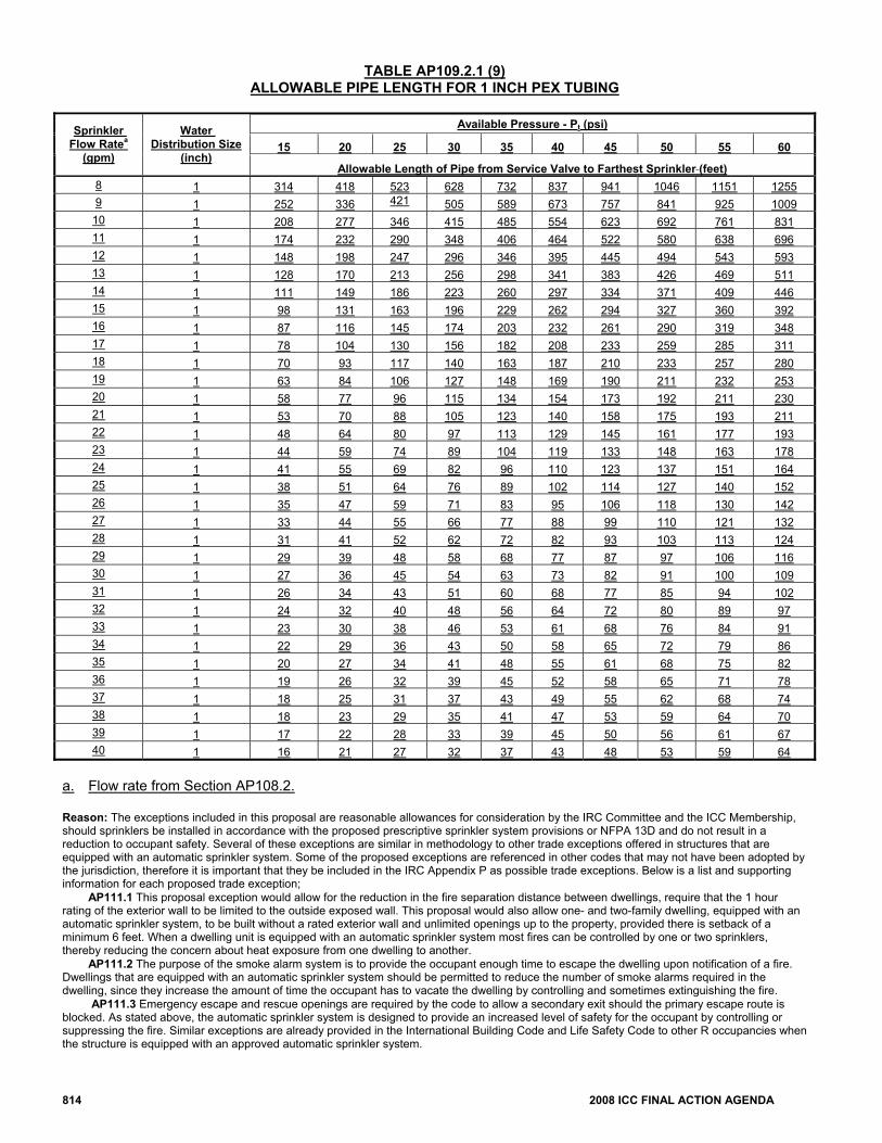
814 2008 ICC FINAL ACTION AGENDA
TABLE AP109.2.1 (9) ALLOWABLE PIPE LENGTH FOR 1 INCH PEX TUBING
Available Pressure - Pt (psi)
15 20 25 30 35 40 45 50 55 60 Sprinkler
Flow Ratea (gpm)
Water Distribution Size
(inch) Allowable Length of Pipe from Service Valve to Farthest Sprinkler (feet)
8 1 314 418 523 628 732 837 941 1046 1151 1255 9 1 252 336 421 505 589 673 757 841 925 1009
10 1 208 277 346 415 485 554 623 692 761 831 11 1 174 232 290 348 406 464 522 580 638 696 12 1 148 198 247 296 346 395 445 494 543 593 13 1 128 170 213 256 298 341 383 426 469 511 14 1 111 149 186 223 260 297 334 371 409 446 15 1 98 131 163 196 229 262 294 327 360 392 16 1 87 116 145 174 203 232 261 290 319 348 17 1 78 104 130 156 182 208 233 259 285 311 18 1 70 93 117 140 163 187 210 233 257 280 19 1 63 84 106 127 148 169 190 211 232 253 20 1 58 77 96 115 134 154 173 192 211 230 21 1 53 70 88 105 123 140 158 175 193 211 22 1 48 64 80 97 113 129 145 161 177 193 23 1 44 59 74 89 104 119 133 148 163 178 24 1 41 55 69 82 96 110 123 137 151 164 25 1 38 51 64 76 89 102 114 127 140 152 26 1 35 47 59 71 83 95 106 118 130 142 27 1 33 44 55 66 77 88 99 110 121 132 28 1 31 41 52 62 72 82 93 103 113 124 29 1 29 39 48 58 68 77 87 97 106 116 30 1 27 36 45 54 63 73 82 91 100 109 31 1 26 34 43 51 60 68 77 85 94 102 32 1 24 32 40 48 56 64 72 80 89 97 33 1 23 30 38 46 53 61 68 76 84 91 34 1 22 29 36 43 50 58 65 72 79 86 35 1 20 27 34 41 48 55 61 68 75 82 36 1 19 26 32 39 45 52 58 65 71 78 37 1 18 25 31 37 43 49 55 62 68 74 38 1 18 23 29 35 41 47 53 59 64 70 39 1 17 22 28 33 39 45 50 56 61 67 40 1 16 21 27 32 37 43 48 53 59 64
a. Flow rate from Section AP108.2. Reason: The exceptions included in this proposal are reasonable allowances for consideration by the IRC Committee and the ICC Membership, should sprinklers be installed in accordance with the proposed prescriptive sprinkler system provisions or NFPA 13D and do not result in a reduction to occupant safety. Several of these exceptions are similar in methodology to other trade exceptions offered in structures that are equipped with an automatic sprinkler system. Some of the proposed exceptions are referenced in other codes that may not have been adopted by the jurisdiction, therefore it is important that they be included in the IRC Appendix P as possible trade exceptions. Below is a list and supporting information for each proposed trade exception; AP111.1 This proposal exception would allow for the reduction in the fire separation distance between dwellings, require that the 1 hour rating of the exterior wall to be limited to the outside exposed wall. This proposal would also allow one- and two-family dwelling, equipped with an automatic sprinkler system, to be built without a rated exterior wall and unlimited openings up to the property, provided there is setback of a minimum 6 feet. When a dwelling unit is equipped with an automatic sprinkler system most fires can be controlled by one or two sprinklers, thereby reducing the concern about heat exposure from one dwelling to another. AP111.2 The purpose of the smoke alarm system is to provide the occupant enough time to escape the dwelling upon notification of a fire. Dwellings that are equipped with an automatic sprinkler system should be permitted to reduce the number of smoke alarms required in the dwelling, since they increase the amount of time the occupant has to vacate the dwelling by controlling and sometimes extinguishing the fire. AP111.3 Emergency escape and rescue openings are required by the code to allow a secondary exit should the primary escape route is blocked. As stated above, the automatic sprinkler system is designed to provide an increased level of safety for the occupant by controlling or suppressing the fire. Similar exceptions are already provided in the International Building Code and Life Safety Code to other R occupancies when the structure is equipped with an approved automatic sprinkler system.
2008 ICC FINAL ACTION AGENDA 815
AP111.4 The IRC Commentary explains that Arc-Fault receptacles are required to reduce the number of fires that are associated with electrical arcs. Based on information provided in reports published by the National Fire Protection Association prior to the code requiring arc-fault protection, the number of fires who’s origin was based on an electrical distribution and lighting failure or malfunction accounted for 3% of all residential structure fires and caused the least number of fire fatalities. AP112 When the sizing of the water meter and distribution line must be increased to accommodate an automatic sprinkler system, the fees assessed by the water purveyor should be based solely on the size meter and distribution lines that would be required to meet the domestic potable demand. Unless the sprinkler is activated, there is no increase in the amount of water consumed by the dwelling. Consumers should not be charged higher rates or fees, just because the sprinkler system design required the distribution system to be increased. AP113.2 The purpose of this proposal is to follow a precedence that has been established in the International Residential Code when referencing another code. The International Fire Code allow the Authority Having Jurisdiction to reduce the required fire flow rate by 50 percent when the dwelling is provided with an approved sprinkler system. AP113.3 Would allow greater distances between fire hydrants in residential developments where all dwellings are equipped with an automatic sprinkler system in accordance with Appendix P. Both the Uniform fire Code and the Urban- Wildland Interface Code allow for increase to the fire hydrant spacing when all dwelling units in a development are equipped with an automatic sprinkler system. The spacing increase to 1,000 feet would still meet the UFC requirement for response to vehicular accidents and the WUIC requirement for maximum distance to a water source. AP113.4 This proposed exception would allow for the increase the number of dwelling units allowed before requiring a secondary fire apparatus access road and would allow for the reduction of the access road to less than 20 feet when all the dwellings are equipped with an approved automatic sprinkler system. The International Fire Code allows for a single fire apparatus access road for developments that are equipped with an automatic sprinkler system and some jurisdictions have allowed for narrower roads as an exception when dwellings are sprinklered. Cost Impact: The code change proposal will increase the cost of construction. Committee Action: Approved as Submitted Committee Reason: “The committee prefers that methods for residential sprinklers in the Appendix of the code and not in the mandatory part of the code.” Assembly Action: Disapproved Individual Consideration Agenda This item is on the agenda for individual consideration because an assembly action was successful and public comments were submitted. Public Comment 1: Steve Orlowski, National Association of Home Builders (NAHB), requests Approval as Submitted. Commenter=s Reason: The intent of this proposal is to provide a code official with the necessary tools to perform a plan review and an inspection of a residential fire sprinkler system that is either connected to the domestic water piping system or stand alone. While there are few differences between the two proposals RP-3 and RP-8, the most notable difference between the two proposals was determining where the requirements should be placed in the IRC. To avoid any confusion as to whether or not residential sprinklers are required to be installed, NAHB submitted RP-8 which locates these provisions in the appendix along with the adopting language. The concern over the confusion that RP-3 could create was shared by many of the committee members and prompted the committee to modify the original proposal at the public hearing, where all mandatory language was removed from the proposal. Another advantage of placing these provisions in the appendix is it would allow those jurisdictions who currently do not adopt the plumbing section of the IRC (ex: the State of North Carolina and Oregon) to adopt these provisions through the appendix. Public Comment 2: Ronny J. Coleman, Retired California State Fire Marshal, representing IRC Fire Sprinkler Coalition, requests Disapproval. Commenter=s Reason: The Coalition is interested in making the code clear and understandable regarding residential sprinkler requirements. This code change is unnecessary with the Committee’s acceptance of RP3. While these two code changes are similar, they are not identical. The acceptance of RP8 would confuse everyone as to which requirement applies. The Coalition agrees that it is appropriate to have the requirements in the body of the code as shown in RP3, which is consistent with the membership floor vote in Palm Springs. The membership understood that adopting RP8 in addition to RP3 was a mistake, and it is clear from testimony and the floor vote that the membership preferred RP3. Final Action: AS AM AMPC D

816 2008 ICC FINAL ACTION AGENDA