INTERNATIONAL MARITIME ORGANIZATION Eimo.udhb.gov.tr/dosyam/EKLER/yak6.pdfNOTING that ISO had, in...
13
I:\ASSEMBLY\23\RES\952.DOC For reasons of economy, this document is printed in a limited number. Delegates are kindly asked to bring their copies to meetings and not to request additional copies. INTERNATIONAL MARITIME ORGANIZATION IMO E ASSEMBLY 23rd session Agenda item 17 A 23/Res.952 25 February 2004 Original: ENGLISH Resolution A.952(23) Adopted on 5 December 2003 (Agenda item 17) GRAPHICAL SYMBOLS FOR SHIPBOARD FIRE CONTROL PLANS THE ASSEMBLY, RECALLING Article 15(i) of the Convention on the International Maritime Organization concerning the functions of the Assembly in relation to regulations and guidelines concerning maritime safety, BEARING IN MIND that regulation II-2/15.2.4 of the International Convention for the Safety of Life at Sea (SOLAS), 1974, as amended, requires that fire control plans be permanently exhibited for the guidance of the ships officers and that a duplicate set of fire control plans or a booklet containing such plans be permanently stored in a prominently marked weathertight enclosure outside the deckhouse for the assistance of shore-side fire-fighting personnel, RECOGNIZING that the use of international symbols for shipboard fire control plans would greatly increase their usefulness, both for the crew of the ship and for shore-based fire brigades, RECALLING ALSO resolution A.654(16) on Graphical symbols for fire control plans, NOTING that ISO had, in close co-operation with IMO, developed standard ISO 17631:2002 Ships and marine technology Shipboard plans for fire protection, life-saving appliances and means of escape, providing fire protection symbols which generally conform to the corresponding symbols set out in resolution A.654(16), NOTING IN PARTICULAR that, through MSC/Circ.1050, Member Governments had been invited to bring standard ISO 17631:2002 to the attention of shipbuilders, shipowners, shipoperators, shipmasters, shore-based fire-fighting personnel and other parties concerned with the preparation or use of shipboard fire control plans, so that they might use it, on a voluntary basis, for the preparation or use of the shipboard fire control plans required by SOLAS regulation II-2/15.2.4, pending the outcome of the work related to the revision of resolution A.654(16),
Transcript of INTERNATIONAL MARITIME ORGANIZATION Eimo.udhb.gov.tr/dosyam/EKLER/yak6.pdfNOTING that ISO had, in...
I:\ASSEMBLY\23\RES\952.DOC
For reasons of economy, this document is printed in a limited number. Delegates are kindly asked to bring their copies to meetings and not to request additional copies.
INTERNATIONAL MARITIME ORGANIZATION
IMO
E
ASSEMBLY 23rd session Agenda item 17
A 23/Res.952 25 February 2004 Original: ENGLISH
Resolution A.952(23)
Adopted on 5 December 2003 (Agenda item 17)
GRAPHICAL SYMBOLS FOR SHIPBOARD FIRE CONTROL PLANS THE ASSEMBLY,
RECALLING Article 15(i) of the Convention on the International Maritime Organization concerning the functions of the Assembly in relation to regulations and guidelines concerning maritime safety,
BEARING IN MIND that regulation II-2/15.2.4 of the International Convention for the Safety of Life at Sea (SOLAS), 1974, as amended, requires that fire control plans be permanently exhibited for the guidance of the ship�s officers and that a duplicate set of fire control plans or a booklet containing such plans be permanently stored in a prominently marked weathertight enclosure outside the deckhouse for the assistance of shore-side fire-fighting personnel,
RECOGNIZING that the use of international symbols for shipboard fire control plans would greatly increase their usefulness, both for the crew of the ship and for shore-based fire brigades,
RECALLING ALSO resolution A.654(16) on Graphical symbols for fire control plans,
NOTING that ISO had, in close co-operation with IMO, developed standard ISO 17631:2002 � Ships and marine technology � Shipboard plans for fire protection, life-saving appliances and means of escape, providing fire protection symbols which generally conform to the corresponding symbols set out in resolution A.654(16),
NOTING IN PARTICULAR that, through MSC/Circ.1050, Member Governments had been invited to bring standard ISO 17631:2002 to the attention of shipbuilders, shipowners, shipoperators, shipmasters, shore-based fire-fighting personnel and other parties concerned with the preparation or use of shipboard fire control plans, so that they might use it, on a voluntary basis, for the preparation or use of the shipboard fire control plans required by SOLAS regulation II-2/15.2.4, pending the outcome of the work related to the revision of resolution A.654(16),

A 23/Res.952 - 2 -
I:\ASSEMBLY\23\RES\952.DOC
HAVING CONSIDERED the recommendation made by the Maritime Safety Committee at its seventy-seventh session, 1. ADOPTS the Graphical symbols for shipboard fire control plans, set out in the Annex to the present resolution; 2. URGES Governments to bring the aforementioned graphical symbols to the attention of shipbuilders, shipowners, shipoperators, shipmasters, shore-based fire-fighting personnel and other parties concerned with the preparation or use of shipboard fire control plans with a view to encouraging their use for the preparation of the shipboard fire control plans required by SOLAS regulation II-2/15.2.4, for ships constructed on or after 1 January 2004; 3. INVITES Governments to bring standard ISO 17631:2002 to the attention of shipbuilders, shipowners, shipoperators and shipmasters so that they may use the additional guidance contained therein for the preparation of shipboard fire control plans; 4. AGREES that ships constructed before 1 January 2004 may continue to carry fire control plans that use the graphical symbols contained in resolution A.654(16); 5. REQUESTS the Maritime Safety Committee to keep this resolution under review and to amend it as necessary.
- 3 - A 23/Res.952
I:\ASSEMBLY\23\RES\952.DOC
ANNEX
GRAPHICAL SYMBOLS FOR SHIPBOARD FIRE CONTROL PLANS*
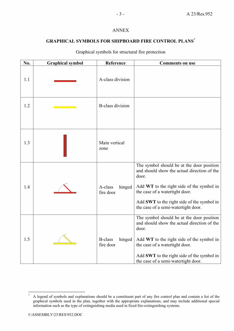
Graphical symbols for structural fire protection
No. Graphical symbol Reference Comments on use 1.1
A-class division
1.2
B-class division
1.3
Main vertical zone
1.4
A-class hinged fire door
The symbol should be at the door position and should show the actual direction of the door.
Add WT to the right side of the symbol in the case of a watertight door.
Add SWT to the right side of the symbol in the case of a semi-watertight door.
1.5
B-class hinged fire door
The symbol should be at the door position and should show the actual direction of the door. Add WT to the right side of the symbol in the case of a watertight door. Add SWT to the right side of the symbol in the case of a semi-watertight door.
* A legend of symbols and explanations should be a constituent part of any fire control plan and contain a list of the
graphical symbols used in the plan, together with the appropriate explanations, and may include additional special information such as the type of extinguishing media used in fixed fire-extinguishing systems.

A 23/Res.952 - 4 -
I:\ASSEMBLY\23\RES\952.DOC
No. Graphical symbol Reference Comments on use 1.6
A-class hinged self-closing fire door
The symbol should be at the door position and should show the actual direction of the door. Add WT to the right side of the symbol in the case of a watertight door. Add SWT to the right side of the symbol in the case of a semi-watertight door.
1.7
B-class hinged self-closing fire door
The symbol should be at the door position and should show the actual direction of the door. Add WT to the right side of the symbol in the case of a watertight door. Add SWT to the right side of the symbol in the case of a semi-watertight door.
1.8
A-class sliding fire door
The symbol should be at the door position and should show the actual direction of the door. Add WT to the right side of the symbol in the case of a watertight door. Add SWT to the right side of the symbol in the case of a semi-watertight door.
1.9
B-class sliding fire door
The symbol should be at the door position and should show the actual direction of the door. Add WT to the right side of the symbol in the case of a watertight door. Add SWT to the right side of the symbol in the case of a semi-watertight door.

- 5 - A 23/Res.952
I:\ASSEMBLY\23\RES\952.DOC
No. Graphical symbol Reference Comments on use
1.10
A-class self-closing sliding
fire door
The symbol should be at the door position and should show the actual direction of the door. Add WT to the right side of the symbol in the case of a watertight door. Add SWT to the right side of the symbol in the case of a semi-watertight door.
1.11
B-class self-closing sliding
fire door
The symbol should be at the door position and should show the actual direction of the door. Add WT to the right side of the symbol in the case of a watertight door. Add SWT to the right side of the symbol in the case of a semi-watertight door.
1.12
Ventilation remote control or
shut-off
Colour of the circle and a letter at the right side of the symbol should indicate as follows: A = blue for accommodation and service
spaces; M = green for machinery spaces; C = yellow for cargo spaces.
1.13
Remote control
for skylight
1.14
Remote control for watertight doors or fire
doors
Add WT to the right side of the symbol to indicate remote control for watertight doors or FD to indicate remote control for fire doors.

A 23/Res.952 - 6 -
I:\ASSEMBLY\23\RES\952.DOC
No. Graphical symbol Reference Comments on use
1.15
Fire damper
Colour of the circle and a letter at the right side of the symbol should indicate as follows: A = blue for accommodation and service
spaces; M = green for machinery spaces; C = yellow for cargo spaces. Identification number of the damper may be shown at the bottom of the symbol.
1.16
Closing device for ventilation inlet or outlet
Colour of the circle and a letter at the right side of the symbol should indicate as follows: A = blue for accommodation and service
spaces; M = green for machinery spaces; C = yellow for cargo spaces. Identification number of the closing device may be shown at the bottom of the symbol.
1.17
Remote control for fire
damper(s)
Colour of the circle and a letter at the right side of the symbol should indicate as follows: A = blue for accommodation and service
spaces; M = green for machinery spaces; C = yellow for cargo spaces. Identification number of the damper may be shown.

- 7 - A 23/Res.952
I:\ASSEMBLY\23\RES\952.DOC
No. Graphical symbol Reference Comments on use
1.18
Remote control for closing
device(s) for ventilation inlet
and outlet
Colour of the circle and a letter at the right side of the symbol should indicate as follows: A = blue for accommodation and service
spaces; M = green for machinery spaces; C = yellow for cargo spaces. Identification number of the closing device(s) may be shown.
Graphical symbols for fire-protection appliances
No. Graphical symbol Reference Comments on use
2.1
Fire protection appliances or structural fire
protection plan
2.2
Remote control for fire pump(s)
2.3
Fire pump(s)
The type, quantity of water delivered per time unit, and pressure head should be indicated either at the right side of the symbol or in the legend.
2.4
Remote control for emergency
fire pump or fire pump supplied
by the emergency
source of power
2.5
Emergency fire
pump
The type, quantity of water delivered per time unit, and pressure head should be indicated either at the right side of the symbol or in the legend.

A 23/Res.952 - 8 -
I:\ASSEMBLY\23\RES\952.DOC
No. Graphical symbol Reference Comments on use
2.6
Fuel pump(s)
remote shut-off
2.7
Lube oil pump(s) remote shut-off
2.8
Remote control
for bilge pump(s)
2.9
Remote control for emergency
bilge pump
2.10
Remote control
for fuel oil valves
2.11
Remote control
for lube oil valves
2.12
Remote control for fire pump
valve(s)
2.13
Remote release station
Indicate at the bottom of the symbol the protected space. Extinguishing media should be colour coded in the lower part of the symbol and be indicated by a letter at the right side of the symbol as follows: grey � CO2 for carbon dioxide or N for nitrogen, brown � H for gas other than CO2 or N (type of gas to be indicated), white � P for powder, green � W for water.

- 9 - A 23/Res.952
I:\ASSEMBLY\23\RES\952.DOC
No. Graphical symbol Reference Comments on use
2.14
International
shore connection
2.15
Fire hydrant
2.16
Fire main section
valve
Indicate the reference number of the valve at the right side of the symbol.
2.17
Sprinkler section valve
Indicate the reference number of the valve at the right side of the symbol. This symbol may also be applied to equivalent water-extinguishing systems. Valves for automatic dry-pipe sprinkler systems should be indicated in the legend.
2.18
Powder section
valve
Indicate the reference number of the valve at the right side of the symbol.
2.19
Foam section
valve
Indicate the reference number of the valve at the right side of the symbol.
2.20
Fixed fire-extinguishing installation
Extinguishing media should be colour-coded in the centre part of the symbol and indicated by a letter on top of the symbol as follows: grey � CO2 for carbon dioxide or N for nitrogen, yellow � F for foam, brown � H for gas other than CO2 or N (type of gas to be indicated), white � P for powder, green � W for water.
A 23/Res.952 - 10 -
I:\ASSEMBLY\23\RES\952.DOC
No. Graphical symbol Reference Comments on use
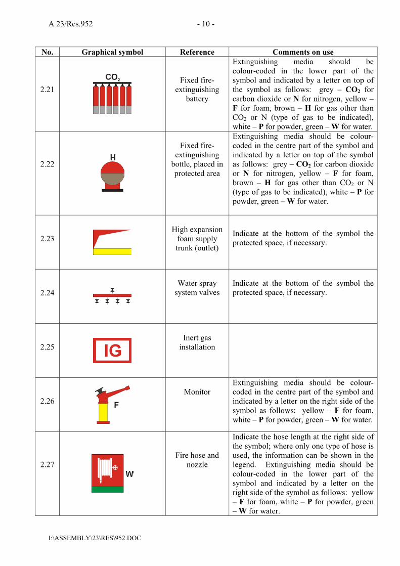
2.21
Fixed fire-extinguishing
battery
Extinguishing media should be colour-coded in the lower part of the symbol and indicated by a letter on top of the symbol as follows: grey � CO2 for carbon dioxide or N for nitrogen, yellow � F for foam, brown � H for gas other than CO2 or N (type of gas to be indicated), white � P for powder, green � W for water.
2.22
Fixed fire-
extinguishing bottle, placed in protected area
Extinguishing media should be colour-coded in the centre part of the symbol and indicated by a letter on top of the symbol as follows: grey � CO2 for carbon dioxide or N for nitrogen, yellow � F for foam, brown � H for gas other than CO2 or N (type of gas to be indicated), white � P for powder, green � W for water.
2.23
High expansion
foam supply trunk (outlet)
Indicate at the bottom of the symbol the protected space, if necessary.
2.24
Water spray
system valves
Indicate at the bottom of the symbol the protected space, if necessary.
2.25
Inert gas
installation
2.26
Monitor
Extinguishing media should be colour-coded in the centre part of the symbol and indicated by a letter on the right side of the symbol as follows: yellow � F for foam, white � P for powder, green � W for water.
2.27
Fire hose and nozzle
Indicate the hose length at the right side of the symbol; where only one type of hose is used, the information can be shown in the legend. Extinguishing media should be colour-coded in the lower part of the symbol and indicated by a letter on the right side of the symbol as follows: yellow � F for foam, white � P for powder, green � W for water.

- 11 - A 23/Res.952
I:\ASSEMBLY\23\RES\952.DOC
No. Graphical symbol Reference Comments on use
2.28
Fire extinguisher
Indicate type of extinguishing media (CO2 for carbon dioxide, F for foam, H for gas other than CO2 (type of gas to be indicated), P for powder, W for water) and capacity (kg for gas and powder, litres for water and foam) at the right side of the symbol. Media should be colour-coded in the lower part of the symbol as follows: grey for carbon dioxide, yellow for foam, brown for gas other than CO2, white for powder, green for water.
2.29
Wheeled fire extinguisher
Indicate type of extinguishing media (CO2 for carbon dioxide, F for foam, H for gas other than CO2 (type of gas to be indicated), P for powder, W for water) and capacity (kg for gas and powder, litres for water and foam) at the right side of the symbol. Media should be colour-coded in the centre part of the symbol as follows: grey for carbon dioxide, yellow for foam, brown for gas other than CO2, white for powder, green for water.
2.30
Portable foam
applicator unit or relevant spare
tank(s)
2.31
Fire locker
Indicate the number of the fire locker at the right side of the symbol. The principal contents of each fire locker should be indicated in the legend.
2.32
Space or group of spaces
protected by fire-extinguishing
system
Indicate type of extinguishing media (CO2 for carbon dioxide, F for foam, H for gas other than CO2 (type of gas to be indicated), P for powder, W for water, S for sprinkler or high pressure water extinguishing system) and capacity (kg for gas and powder, litres for water and foam) at the top of the symbol. Add suffix �L� for fixed local application fire fighting system. Media should be colour-coded in the symbol as follows: grey for carbon dioxide, yellow for foam, brown for gas other than CO2, white for powder, green for water, orange for sprinkler or high pressure water extinguishing system.

A 23/Res.952 - 12 -
I:\ASSEMBLY\23\RES\952.DOC
No. Graphical symbol Reference Comments on use
2.33
Water fog applicator
2.34
Emergency source of
electrical power (generator)
2.35
Emergency source of
electrical power (battery)
2.36
Emergency switchboard
2.37
Air compressor for breathing
devices
2.38
Control panel for
fire detection and alarm
system
2.39
Push
button/switch for general alarm
2.40
Manually
operated call point
The use of this symbol is optional at the discretion of the competent authority.

- 13 - A 23/Res.952
I:\ASSEMBLY\23\RES\952.DOC
No. Graphical symbol Reference Comments on use
2.41
Space or group
of spaces monitored by
smoke detector(s)
The space(s) should be identified.
2.42
Space or group
of spaces monitored by
heat detector(s)
The space(s) should be identified.
2.43
Space or group
of spaces monitored by
flame detector(s)
The space(s) should be identified.
2.44
Space monitored by gas
detector(s)
Graphical symbols for means of escape and escape-related devices
3.1
Primary escape
route
3.2
Secondary
escape route
3.3
Emergency
escape breathing device (EEBD)
Indicate the quantity of the EEBDs stowed at the right side of the symbol.
__________

![JHEP06(2016)156 a and Andrew Spray2016)156.pdfnoting that the studies of refs. [37,38] nd evidence for a point source origin of the GCE. In any case, we nd it interesting to consider](https://static.fdocuments.us/doc/165x107/600067fae010325f7d6e6446/jhep062016156-a-and-andrew-spray-2016156pdf-noting-that-the-studies-of-refs.jpg)