International Journal of Impact Engineering - me.sc. · PDF fileentropy (max-ent) meshfree ......
12
Verification and validation of the Optimal Transportation Meshfree (OTM) simulation of terminal ballistics B. Li, A. Kidane, G. Ravichandran, M. Ortiz * Graduate Aeronautical Laboratories, California Institute of Technology, Pasadena, CA, USA article info Article history: Received 11 April 2011 Received in revised form 9 November 2011 Accepted 10 November 2011 Available online 25 November 2011 Keywords: Optimal transportation Local max-ent interpolation Material-point sampling Material-point failure Ballistic impact abstract We evaluate the performance of the Optimal Transportation Meshfree (OTM) method of Li et al. [21], suitably extended to account for seizing contact and fracture, in applications involving terminal ballistics. The evaluation takes the form of a conventional Verification and Validation (V&V) analysis. In support of the validation analysis, we have conducted tests concerned with the normal impact of Aluminum alloy 6061-T6 thin plates by S2 tool steel spherical projectile over a range of plate thicknesses of [0.8 mm, 1.6 mm] and a range of impact velocities of [100, 400]m/s. The tests were conducted at Caltech’s GALCIT gas-gun Plate-Impact Facility. We find excellent agreement between measured and computed perfora- tion areas and a ballistic limits over the thickness and velocity ranges considered. Our verification analysis consists of model-on-model comparisons and an assessment of the convergence of the OTM method. Specifically, we find excellent agreement between the incident vs. residual velocities predicted by the OTM method and by the power-law relation of Recht and Ipson [36]. We also find robust linear convergence of the OTM method as measured in terms of residual velocity error vs. number of nodes. Ó 2011 Elsevier Ltd. All rights reserved. 1. Introduction Ballistic penetration of metallic armor supplies an exacting validation and verification test that probes the very limits of predictability of any numerical scheme (cf., e.g., [1,2,5,6,19,51] for reviews). Thus, the ballistic penetration of ductile targets involves large unconstrained plastic flows, contact and friction, fracture and fragmentation and complex material behavior. A number of strat- egies have been devised with a view to meeting these challenges, including: Eulerian formulations [6,28e30]; particle methods such as smooth particle hydrodynamics (SPH) [16,23,24,31,39,45,50]; the material-point method [40,42,49]; Lagrangian formulations with continuous adaptive remeshing [10,27,47]; arbitrary- Lagrangian-Eulerian (ALE) and related formulations [11]; element erosion [9,13e15,37,43,44]; meshfree methods [21]; and others. Many appealing features notwithstanding, some of these methods still suffer from a variety of shortcomings, including: the intro- duction of large numerical diffusion errors; large discretization errors at fluidesolid interfaces; the need for background meshes; difficulties in maintaining monotonicity, positivity and in tracking state variables; lack of strict conservation properties; spurious modes and tensile instabilities; mesh entanglement; the need to remesh or rezone arbitrary three-dimensional domains; variable mass matrices; the remapping of state variables; ad-hoc transition or blending regions; difficulties in defining numerical integration rules and satisfying essential boundary conditions; unknown convergence and stability properties; and others. A method with the potential to overcome these difficulties is the Optimal-Transportation MeshFree (OTM) method of Li et al. [21]. The OTM method combines: i) optimal transportation concepts such as the Wasserstein distance between successive mass densi- ties in order to discretize the action integral in time; ii) Maximum- entropy (max-ent) meshfree interpolation [3] from a nodal-point set in order to avoid mesh entanglement and the need for contin- uous remeshing in simulations of unconstrained flows; and iii) material-point sampling in order to track the local state of material points and carry out complex constitutive updates. The optimal transportation approach to time discretization leads to geometrically-exact updates of the local volumes and mass densi- ties, thus bypassing the need for solving a costly Poisson equation for the pressure and entirely eliminating the mass conservation errors that afflict Eulerian formulations. In addition, by adopting a discrete Hamilton principle based on a time-discrete action fur- nished by optimal transportation, the discrete trajectories have exact conservation properties including symplecticity, linear and angular momentum. The total energy can also be exactly conserved, subject to solvability constraints, if time is taken as an independent generalized coordinate and the successive time steps are computed so as to render the action stationary [17]. Max-ent interpolation [3] offers the advantage of being mesh-free and entirely defin- edeessentially explicitlyeby the current nodal-set positions. In * Corresponding author. E-mail address: [email protected] (M. Ortiz). Contents lists available at SciVerse ScienceDirect International Journal of Impact Engineering journal homepage: www.elsevier.com/locate/ijimpeng 0734-743X/$ e see front matter Ó 2011 Elsevier Ltd. All rights reserved. doi:10.1016/j.ijimpeng.2011.11.003 International Journal of Impact Engineering 42 (2012) 25e36
Transcript of International Journal of Impact Engineering - me.sc. · PDF fileentropy (max-ent) meshfree ......

at SciVerse ScienceDirect
International Journal of Impact Engineering 42 (2012) 25e36
Contents lists available
International Journal of Impact Engineering
journal homepage: www.elsevier .com/locate/ i j impeng
Verification and validation of the Optimal Transportation Meshfree (OTM)simulation of terminal ballistics
B. Li, A. Kidane, G. Ravichandran, M. Ortiz*
Graduate Aeronautical Laboratories, California Institute of Technology, Pasadena, CA, USA
a r t i c l e i n f o
Article history:Received 11 April 2011Received in revised form9 November 2011Accepted 10 November 2011Available online 25 November 2011
Keywords:Optimal transportationLocal max-ent interpolationMaterial-point samplingMaterial-point failureBallistic impact
* Corresponding author.E-mail address: [email protected] (M. Ortiz).
0734-743X/$ e see front matter � 2011 Elsevier Ltd.doi:10.1016/j.ijimpeng.2011.11.003
a b s t r a c t
We evaluate the performance of the Optimal Transportation Meshfree (OTM) method of Li et al. [21],suitably extended to account for seizing contact and fracture, in applications involving terminal ballistics.The evaluation takes the form of a conventional Verification and Validation (V&V) analysis. In support ofthe validation analysis, we have conducted tests concerned with the normal impact of Aluminum alloy6061-T6 thin plates by S2 tool steel spherical projectile over a range of plate thicknesses of [0.8 mm,1.6 mm] and a range of impact velocities of [100, 400]m/s. The tests were conducted at Caltech’s GALCITgas-gun Plate-Impact Facility. We find excellent agreement between measured and computed perfora-tion areas and a ballistic limits over the thickness and velocity ranges considered. Our verificationanalysis consists of model-on-model comparisons and an assessment of the convergence of the OTMmethod. Specifically, we find excellent agreement between the incident vs. residual velocities predictedby the OTM method and by the power-law relation of Recht and Ipson [36]. We also find robust linearconvergence of the OTM method as measured in terms of residual velocity error vs. number of nodes.
� 2011 Elsevier Ltd. All rights reserved.
1. Introduction or blending regions; difficulties in defining numerical integration
Ballistic penetration of metallic armor supplies an exactingvalidation and verification test that probes the very limits ofpredictability of any numerical scheme (cf., e.g., [1,2,5,6,19,51] forreviews). Thus, the ballistic penetration of ductile targets involveslarge unconstrained plastic flows, contact and friction, fracture andfragmentation and complex material behavior. A number of strat-egies have been devised with a view to meeting these challenges,including: Eulerian formulations [6,28e30]; particle methods suchas smooth particle hydrodynamics (SPH) [16,23,24,31,39,45,50];the material-point method [40,42,49]; Lagrangian formulationswith continuous adaptive remeshing [10,27,47]; arbitrary-Lagrangian-Eulerian (ALE) and related formulations [11]; elementerosion [9,13e15,37,43,44]; meshfree methods [21]; and others.Many appealing features notwithstanding, some of these methodsstill suffer from a variety of shortcomings, including: the intro-duction of large numerical diffusion errors; large discretizationerrors at fluidesolid interfaces; the need for background meshes;difficulties in maintaining monotonicity, positivity and in trackingstate variables; lack of strict conservation properties; spuriousmodes and tensile instabilities; mesh entanglement; the need toremesh or rezone arbitrary three-dimensional domains; variablemass matrices; the remapping of state variables; ad-hoc transition
All rights reserved.
rules and satisfying essential boundary conditions; unknownconvergence and stability properties; and others.
A methodwith the potential to overcome these difficulties is theOptimal-Transportation MeshFree (OTM) method of Li et al. [21].The OTM method combines: i) optimal transportation conceptssuch as the Wasserstein distance between successive mass densi-ties in order to discretize the action integral in time; ii) Maximum-entropy (max-ent) meshfree interpolation [3] from a nodal-pointset in order to avoid mesh entanglement and the need for contin-uous remeshing in simulations of unconstrained flows; and iii)material-point sampling in order to track the local state of materialpoints and carry out complex constitutive updates. The optimaltransportation approach to time discretization leads togeometrically-exact updates of the local volumes and mass densi-ties, thus bypassing the need for solving a costly Poisson equationfor the pressure and entirely eliminating the mass conservationerrors that afflict Eulerian formulations. In addition, by adoptinga discrete Hamilton principle based on a time-discrete action fur-nished by optimal transportation, the discrete trajectories haveexact conservation properties including symplecticity, linear andangularmomentum. The total energy can also be exactly conserved,subject to solvability constraints, if time is taken as an independentgeneralized coordinate and the successive time steps are computedso as to render the action stationary [17]. Max-ent interpolation [3]offers the advantage of being mesh-free and entirely defin-edeessentially explicitlyeby the current nodal-set positions. In

B. Li et al. / International Journal of Impact Engineering 42 (2012) 25e3626
addition, max-ent interpolation satisfies a Kronecker-delta prop-erty at the boundary, which greatly facilitates the enforcement ofessential boundary conditions, and has good accuracy, convergenceand monotonicity conditions that render it well-suited to applica-tions involving shocks. In [3] the authors developed an efficientsolver for the max-ent shape functions based on a standard dualanalysis. Typically, an average of 4 NewtoneRaphson iterations isrequired to calculate the shape function and their derivatives.
In this work, we evaluate the performance of the OTM methodin applications involving terminal ballistics. To this end, we extendthen scope of the method to account for contact and fracture, asrequired in simulations of ballistics. A convenient feature of OTM,which is common to other material point methods [41], is thatseizing contact is accounted for automatically, essentially for free,by simply allowing nodal points from different bodies to belong tothe local neighborhoods of material points. The ensuing cancelationof linear momentum then automatically accounts for dynamiccontact interactions of the seizing type. Dynamic contact may beefficiently detected by fast orthogonal range query algorithms suchas kd-tree and cell search algorithms. In comparison to the penaltymethod, Lagrangian multipliers or other meshfree contact algo-rithms [22], the OTM method provides an efficient alternative forsimulating complex contact events during ballistic impacts. A finalcomponent of the material model concerns the simulation offracture and fragmentation. Specifically, we simulate fracture bya variational material-point failure scheme known as eigenfracture[37]. In this scheme, the energy-release rate attendant to the failureof a material point is estimated by a local energy-averagingprocedure, and material points are failed when the attendantenergy-release rate exceeds the specific fracture energy of thematerial. Unlike other element or material-point erosion schemes,which fail to converge or converge to the wrong limit, the eigen-fracture scheme is known to properly converge to Griffith fracturein the limit of vanishingly small mesh sizes [37]. In particular, thelocal neighborhood averaging of the energy which underlies thecalculation of the effective energy-release has the effect of elimi-nating spurious mesh-dependencies. Because the calculation of theeffective energy-release rate at a material point is carried outwithin a local neighborhood of the point and it requires no explicitrepresentation of the crack, cf. [8,35], the implementation of thematerial-point failure scheme is straightforward.
In order to validate the OTM method, we have conducted testsconcerned with the normal impact of Aluminum alloy 6061-T6 thinplates by S2 tool steel spherical projectile over a range of platethicknesses and impact velocities. The tests were conducted atCaltech’s GALCIT gas-gun Plate-Impact Facility. In all cases, theprojectile remains relatively undeformed and easily perforates theplate by the conventional mechanism of plugging. The experimentsare simulated using the OTM method, engineering models ofthermoviscoplasticity, and assumptions of adiabatic heating and ofa fixed fraction of plastic work converted to heat. The performancemeasures used for validation are the perforation area and theballistic limit. The fidelity of the OTM model is assessed by directcomparison of the predicted and measured performance measures.Because the system under consideration is highly overmatched,both the perforation area and the ballistic limit are highly repro-ducible and exhibit low scatter. In addition, the choice of perfor-mance measures effectively probes all aspects of the model,including thermoviscoplasticity and fracture, over a broad range ofoperating conditions. These features render the experimental setupwell suited and attractive for purposes of model validation. Wehave also verified the OTM model by means of a conventionalconvergence analysis. We specifically determine the convergencerate of the residual velocity as a function of mesh size. Conve-niently, residual velocity errors effectively convolve all modeling
and numerical errors, including those resulting from spatial andtime discretization, which confers the residual velocity value asa convergence indicator. Based on this verification and validationanalysis, we find that the OTM-based model results in robustconvergence and high-fidelity predictions of ballistic performance.
2. Experimental setup
The validation experiments that provide the basis for this workare concerned with the normal impact of Aluminum alloy 6061-T6thin plates by S2 tool steel spherical projectile over a range of platethicknesses and impact velocities. All the tests were conducted atCaltech’s GALCIT gas-gun Plate-Impact Facility. A general view ofthe gas gun and launch package used in the tests is shown in Fig. 1.A total number of 64 in-house ballistics experiments were con-ducted specifically for purposes of validation the OTM method interminal ballistic applications. In all the experiments, the projectilewith diameter 7.9 mm was glued on to a light-weight styrofoamsabot and propelled by a gas gun. The gas gun was filled withhelium with the pressure at the desired value of 20e80 psi,depending on the required velocity in the range. The target plateswith four different nominal thicknesses, 0.8 mm, 1.0 mm, 1.27 mmand 1.6 mm, was positioned at the end of the barrel and attached tothe 25.4 mm wide steel frame. The two vertical edges of the platewere simply supported and the other two edges (top and bottom)were clamped to the steel frame, which results ina 101.6 � 101.6 mm2 target area. Near the impact end of the barrel,light emitting diodes were placed in two orifices on the peripheryof the barrel and two fast-response photo detectors are placed inorifices diametrically opposite to the diodes. When the projectilepasses through these orifices it generates a ramp pulse whoseduration is recorded using a high-speed WaveSurfer 24� oscillo-scope (LeCroy, Chestnut Ridge, NY), which has a bandwidth of200 MHz and a sampling rate of 2.5 Giga samples per second. Theprojectile velocity was then calculated from the time of travel of theprojectile across the two detectors. The resulting projectile velocitywas verified by calculating the pulse duration corresponding to theprojectile crossing a single detector. The velocity of the projectile iscalibrated against gas pressure and can be controlled withina maximum error of 5 m/s. The impact velocities achieved in thetests were in the range of 100e400 m/s. The perforation area wasmeasured using high-precision gage pins and verified usinga surface profile scanning technique. The surface profile scanningtechnique employs a ConoScan 3000 (Optimet, North Andover, MA)which uses a conoscopic holography technology and has a precisionof 10 mm over a scan area of up to 120 � 120 mm2. A typical 3Dsurface conoscopic profile is shown in Fig. 2.
Typical perforation profiles at impact velocities just above theballistic limit are additionally shown in Fig. 3. For impact velocitieswell above the ballistic limit, such as considered in the presentvalidation analysis, perforation takes place by the plugging mech-anism, Fig. 2. Plugging is result of the localization of adiabaticshearing to a narrow ring of material in the plate, followed by thepropagation of a shear crack through the thickness of the plate. Bycontrast, at impact velocities just above the ballistic limit, theplugging mechanism competes with petalling. Indeed, the forma-tion of roughly equispaced petals around the rim of the perforationis clearly visible in Fig. 3.
The ballistic limit Vbl (H), measured as a function of platethickness H, is well-approximated by an empirical power-lawrelation of the form
VblðHÞ ¼ H0
�HD
�s
; (1)

Fig. 1. General view of Caltech’s GALCIT gas-gun Plate-Impact Facility.
B. Li et al. / International Journal of Impact Engineering 42 (2012) 25e36 27
whereas the observed dependence perforation area A (V, H) onimpact velocity V and thickness H is ostensibly obeys the power-law relation
AðV ;HÞ ¼8<:
0; if V < Vbl;
K�HD
�p� VVbl
�m
; otherwise;(2)
where D is the diameter of projectile. A least-squares fit of thecoefficients and exponents in these relations to the test data is
Fig. 2. A typical 3D conoscopic surface profile in an aluminum plate perforat
tabulated in Table 1. The low values of the exponents p and m areindicative of a low sensitivity of the perforation area to the platethickness and impact velocity, respectively.
3. The Optimal Transportation Meshfree (OTM) method andextensions to contact and fracture
In this section we summarize the algorithmic aspects of theOptimal Transportation Meshfree (OTM) method as employed in
ed by a spherical steel striker at velocities well above the ballistic limit.

Fig. 3. Typical perforation area profiles in aluminum plates produced by spherical steel strikers at velocities just above the ballistic limit.
B. Li et al. / International Journal of Impact Engineering 42 (2012) 25e3628
the verification and validation calculations presented in the sequel.A full account of the theoretical foundations of the method anda number of convergence tests may be found in [21]. In addition totransporting mass efficiently, a terminal ballistics solver mustaccount for complex contact, fracture and fragmentationphenomena. A convenient feature of OTM, which is common toother material point methods [41] is that seizing contact isaccounted for automatically, essentially for free, by simply allowingnodal points from different bodies to belong to the local neigh-borhoods of material points. The ensuing cancelation of linearmomentum then automatically accounts for dynamic contactinteractions of the seizing type. A final component of the materialmodel concerns the simulation of fracture and fragmentation.Specifically, we simulate fracture by a variational material-pointfailure scheme known as eigenfracture [37]. In this scheme, theenergy-release rate attendant to the failure of a material point isestimated by a local energy-averaging procedure, and materialpoints are failed when the attendant energy-release rate exceedsthe specific fracture energy of the material. The eigenfracturescheme is known to properly converge to Griffith fracture in thelimit of vanishingly small mesh sizes [37]. These extensions of theOTM method are briefly summarized in this Section forcompleteness.
Table 1Empirical model constants.
H0(m/s) S K (mm2) p m
218.89 0.25 59.12 0.13 0.056
3.1. The Optimal Transportation Meshfree (OTM) method
The aim of the OTMmethod is to approximate a flow at discretetimes t0, t1,.,tk, tkþ1,.To this end, we consider the semi-discreteaction sum
Sdð41;.;4N�1Þ ¼XN�1
k¼0
(12d2W ðrk; rkþ1Þðtkþ1 � tkÞ2
� 12½Uð4kÞ þ Uð4kþ1Þ�
)�ðtkþ1 � tkÞ
(3)
where 4k : B3Rn/Rn is the deformation mapping at time tk, rk isthe corresponding mass density at time tk,
Uð4Þ ¼ZB
f ðV4Þdx (4)
is the free energy of the solid, f (74) is the local free-energy densityper unit volume, and
d2W ðra; rbÞ ¼ infT :B/B
ra ¼ rbdetðVTÞ
ZjTðxÞ � xj2raðxÞdx (5)
is the Wasserstein distance between two mass densities ra and rbover B. For simplicity of exposition, we describe the OTM methodwithin the framework of nonlinear elasticity. Extensions to generalmaterials, including materials exhibiting thermoviscoplasticbehavior, are straightforward with the aid of variational

Fig. 4. Spatial discretization scheme used in the OTM method. The figure describes one step of the application of the method between times tk and tkþ1. The open circles representthe nodal points and the red circles the material points. Bk and Bkþ1 are the configurations of the body at times tk and tkþ1, respectively, and 4k/kþ1 is the corresponding incrementaldeformation mapping. Np,k is the local neighborhood of material point xp,k that supports the local max-ent mesh-free interpolation. (For interpretation of the references to colour inthis figure legend, the reader is referred to the web version of this article.)
B. Li et al. / International Journal of Impact Engineering 42 (2012) 25e36 29
constitutive updates [33]. The term 1=2d2W ðrk; rkþ1Þðtkþ1 � tkÞ inEq. (3) supplies a measure of the inertial action between times tkand tkþ1. We also note that in writing Eq. (3) we have restrictedattention to elastic behavior and unforced systems for simplicity.Extensions accounting for forcing, e.g., in the form of body forces,boundary tractions, and extensions to inelasticity may be found in[21].
In order to render the governing equations fully discrete, weproceed to introduce a spatial discretization of the action Eq. (3), cf.Fig. 4. To this end, we begin by approximating mass densities bypoint masses, namely,
rh;kðxÞ ¼XMp¼1
mpd�x� xp;k
�; (6)
where xp,k represents the position at time tk of a material point ofconstant mass mp and d (x � xp,k) is the Dirac-delta distributioncentered at xp,k, Fig. 4. Li et al. [21] have shown that the constancy ofthe material point masses mp is indeed equivalent to the weaksatisfaction of the continuity equation. To complete the spatialdiscretization, we approximate the incremental deformationmapping as
4h;k/kþ1ðxÞ ¼XNa¼1
xa;kþ1Na;kðxÞ; (7)
where {xa,kþ1,a¼ 1,.,N} is an array of nodal coordinates at time tkþ1and Na,k (x) are conforming shape functions defined over theconfiguration at time tk. All local state data is storedeand consti-tutive calculations are performedeat an evolvingmaterial point set.As their name indicates, material points designate fix materialpoints of the body and, therefore, are convected by the deforma-tion. Material points also carry a fixed volume and mass and servethe purpose of integration points for the calculation of the effectivenodal forces and masses.
In calculations, we specifically use max-ent shape functions [3]computed from the array {xa,k,a ¼ 1,.,N} of nodal coordinates attime tk. Since max-ent shape functions are strongly localized, the
interpolation at a material point xp,k depends solely on the nodescontained in a small local neighborhood N p;k of the material point,Fig. 4. The collection of these local neighborhoods may be regardedas a dynamical connectivity table. In calculations, the local neigh-borhoods are continuously updated using range searches [7] toaccount for the relative motion betweenmaterial points and nodes,and the max-ent shape functions are recalculated at every timestep, which effectively results in a dynamic or on-the-fly recon-nection of nodes and material points. Conveniently, the resultingreconnection between material points and nodes leaves thematerial points invariant, thus entirely eliminating the need forstate-variable remapping.
Inserting these approximations into Eq. (3) we obtain the fully-discrete action
Sh�4h;1;.;4h;N�1
� ¼XN�1
k¼0
XMp¼1
(mp
2jxp;kþ1 � xp;kj2ðtkþ1 � tkÞ2
� 12
hmpf
�V4h;k
�xp;k
��þmpf
��V4h;kþ1
�xp;kþ1
��i)ðtkþ1 � tkÞ;
(8)
where we again consider the unforced elastic case for simplicity.The discrete trajectories now follow from the discrete Hamilton’sprinciple
dSh ¼ 0 (9)
of stationary action.The algorithm resulting from the preceding scheme is listed in
Algorithm 1. We see from Fig. 4 that the OTM scheme can be solvedforward explicitly. This forward solution has the usual structure ofexplicit time-integration and updated-Lagrangian schemes. Inparticular, all the finite kinematics of the motion, including themass density and volume updates, are geometrically exact. Inaddition, the continuous reconstruction of the local material-pointneighborhoods and shape functions has the effect of automatically

Fig. 5. The material point erosion algorithm. Material points are failed according toa provably-convergent critical energy-release rate criterion [37], resulting in thenucleation and propagation of cracks (green line). (For interpretation of the referencesto colour in this figure legend, the reader is referred to the web version of this article.)
Algorithm 1: OTM time step
Require: Initial and final times for time step, tk, tkþ1.Require: Initial nodal coordinates, xk ¼ {xa,k,a ¼ 1,.,N}.Require: Initial material-point coordinates, {xp,k,p ¼ 1,.,M}.Require: Initial shape functions ffNa;kðxp;kÞ; a˛N p;kg; p ¼ 1;.;Mg.Require: Ibid gradients ffVNa;kðxp;kÞ; a˛N p;kg; p ¼ 1;.;Mg.Require: Initial deformation gradients, {Fp,k, p ¼ 1,.,M}.Require: Initial material state at all material points.1: Compute mass matrix Mk, nodal forces fk, accelerations ak ¼ M�1
k fk .2: Update nodal coordinates: xkþ1 ¼ xk þ (tkþ1 � tk) (vk þ 1/2(tkþ1 � tk�1) ak).3: Update nodal velocities: vkþ1 ¼ (xkþ1 � xk)/(tkþ1 � tk).4: Update material-point coordinates: xp,kþ1 ¼ 4k/kþ1 (xp,k), p ¼ 1,.,M.5: Update deformation gradients: Fp,kþ1 ¼ 74k/kþ1 (xp,k) Fp,k, p ¼ 1,.,M.6: Effect constitutive updates at material points.7: Update local material-point neighborhoods N p;kþ1, p ¼ 1,.,M.8: Compute shape functions fNa;kþ1ðxp;kþ1Þ; a˛N p;kþ1g, p ¼ 1,.,M.9: Ibid gradients fVNa;kþ1ðxp;kþ1Þ; a˛N p;kþ1g, p ¼ 1,.,M.
B. Li et al. / International Journal of Impact Engineering 42 (2012) 25e3630
reconnecting the material points and the nodal set, at no cost ofremapping the local states carried by the material points. Thisproperty of the method is particularly convenient for inelasticmaterials whose local material state often includes additionalinternal variable information.
3.2. Seizing-contact algorithm
A particularly convenient feature of OTM, which is common toother material-point based methods [4], is that seizing contact isautomatically accounted for. This is so because of the cancelation oflinear momentum that naturally occurs when colliding nodes comewithin the local neighborhoods of material points. Thus, the linearmomentum of node a follows as [21].
la;k ¼XMp¼1
mpxp;k � xp;k�1
tk � tk�1Na;k
�xp;k
�: (10)
This nodal linear momentum represents an average themomenta of the material points within a certain neighborhoodN a;k of node a. Additionally suppose that the mass matrix Mk inAlgorithm 1 is a lumped mass matrix and that we set the nodalvelocities to vk ¼ M�1
k lk. Then, the nodal velocities themselvesrepresent local mass averages of velocities of the material points,which automatically enforces contact conditions between collidingbodies. We note that Eq. (10) averages all components of velocity,which, in particular, results in vanishing normal and tangentialrelative velocities between bodies in contact. This type of seiz-ingdor infinite coefficient of frictiondcontact may be reasonablyexpected to arise in terminal ballistics as a result of local adiabaticheating and mixing at contact surfaces, and is adopted in all thecalculations presented in this work.
3.3. The variational material-point failure algorithm
Finally, we briefly outline the material-point failure schemeused to simulate fracture and fragmentation phenomena interminal ballistics calculations. Within the context of OTM calcu-lations, fracture can be modeled simply by failing material pointsaccording to an energy-release criterion. When the material pointsare failed, they are neglected from the computation of stresses inthe model, which approximates the presence of cracks. FollowingOrtiz et al. [32] and Fraternali et al. [37] we compute the energy-release rate attendant to the failure of material point p as
Gp;kþ1 ¼ Cεmp;kþ1
Xxq;kþ1˛Bεðxp;kþ1Þ
mqfk�Fq;kþ1
�; (11)
where Bε(xp,kþ1) is the ball of radius ε centered at xp,kþ1, or
ε-neighborhood of the material point, cf. Fig. 5,
mp;kþ1 ¼X
xq;kþ1˛Bεðxp;kþ1Þmq (12)
is the mass of the ε-neighborhood and C is a normalizing constant.The averaging radius ε defines a length scale intermediate
between the discretization size and the macroscopic size of thebodies. The material point is failed when
Gp;kþ1 � Gc; (13)
where Gc is a critical energy-release rate that measures thematerial-specific energy required to create a fracture surface of unitarea. For linear elasticity, Fraternali et al. [37] have shown thatcriterion Eqs. (11) and (13) result in approximations that convergeto Griffith fracture in the limit of an infinitely fine discretization.
4. Verification and validation results
In this section, we present the results of a verification andvalidation analysis of the OTM method described in the foregoing.We verify the OTMmodel by means of a conventional convergenceanalysis. We specifically determine the convergence rate of theresidual velocity as a function of mesh size. The validate the OTMmodel by direct comparison of two predicted and measuredperformance measures: the ballistic limit and the perforation area.
4.1. Constitutive model
In all calculations, the materials for the target and projectile aredescribed by means of J2-viscoplasticity models with power-lawhardening, rate-sensitivity and thermal softening (cf., e.g.,[10,47]). Specifically, the rate-sensitivity law is assumed to be of theform:

Table 2Mechanical constants.
Material r (kg/m3) E (GPa) n sy (MPa) εp0 n _ε
p0 m
Al6061-T6 2700 69 0.33 276 0.001 13.5 1000 11.5S2 tool steel 12,695 193 0.3 2000 0.001 22 1 340
Table 3Thermal constants.
Material c (J/kgK) T0 (K) Tm (K) l b
Al6061-T6 896 298 853 0.5 0.9S2 Tool steel 477 298 1777 1.17 0.9
B. Li et al. / International Journal of Impact Engineering 42 (2012) 25e36 31
_εp ¼ _εp0
�s� scðεp; TÞ
s0
�m
(14)
where εp is the Mises effective plastic strain, s is a Mises effective
stress, T is the absolute temperature, _εp0 is a reference effectiveplastic-strain rate, s0 is a reference stress and m is the rate-sensitivity exponent. The critical stress for plastic yielding isassumed of the form
scðεp; TÞ ¼ YðTÞ�1þ
�εp
εp0
�1=n(15)
where Y (T) is the yield stress, εp0 is a reference effective plasticstrain, and n is the hardening exponent. Finally, the yield stress isassumed of the form
YðTÞ ¼ sy
�1� T � T0
Tm � T0
�l
(16)
where sy is the yield stress at reference absolute temperature, T0and Tm is the reference and melting temperature respectively, and lis the thermal softening exponent. The elastic response is assumedto be quadratic in the elastic logarithmic strains, with isotropicelastic coefficients depending linearly on temperature and van-ishing at the melting temperature. The equation of state, whichgoverns the volumetric response of the material, is assumed to beof the MieeGruneisen type. Under ballistic impact conditions, thetemperature increase experienced by the projectile/target may besignificant, which necessitates the concurrent solution of themechanical and thermal field equations. In this paper we assumeadiabatic heating, with heat generated due to plastic work only.
Fig. 6. a) Geometry of computational model and boundary conditions. b) Examples of do
Specifically, we compute the rate of heating per unit undeformedvolume as
S ¼ b _Wp
(17)
where b is the TayloreQuinney coefficient and _Wpis the plastic
power per unit deformed volume. The effect of the rate of adiabaticheating on ballistic performance has been investigated in [47].Higher-fidelity models of adiabatic heating accounting for itsdependence on deformation, deformation rate and temperature areavailable [12,38,48], but such enhancements are beyond the scopeof the present work. The material parameters have been chosenaccording to the related literature [47] and collected in Table 2 andTable 3. The rate sensitivity behavior of Al6061-T6 at high strainrate above 103 s�1 is described by Yadav et al [46].
4.2. Numerical simulations
The geometry and boundary conditions employed in thecalculations are schematically shown in Fig. 6a. These solid modeland boundary conditions exactly match the configurational setup.A typical discretization of the domain of analysis is shown in Fig. 6b.Asmay be seen from the figure, the node andmaterial point densityis higher in the region of impactdand is decreased away fromitdin order to provide the highest possible resolution of theperforation process with a minimum of degrees of freedom. Themechanical and thermal computations are staggered assumingconstant temperature during the mechanical step and constantheat generation during the thermal step. Following Lemonds andNeedleman [20], a mechanical step is taken first based on thecurrent distribution of temperatures, and the heat generation iscomputed from Eq. (17) and the discrete thermal equations. Theresulting temperatures are then used in the mechanical step and
main discretizations with nodes and material points used in the OTM calculations.

Fig. 7. Penetration of 0.8 mm aluminum plate at impact velocity 106 m/s.
B. Li et al. / International Journal of Impact Engineering 42 (2012) 25e3632
incorporated into the thermal softening model Eq. (16) and theMieeGruneisen equation of state, which completes one time-stepping cycle.
All calculations have been carried out in the Shared Heteroge-neous Cluster (SHC) of Caltech’s Center for Advanced ComputingResearch (CACR). The SHC configuration consists of 229 AMD dualprocessor nodes with an Infiniband connection. A speed-up is ob-tained by taking advantage of parallelization using PThreads. In ourthree-dimensional runs, the target and projectile discretizationinclude on the order of 5 � 104 material points and required on theorder of 3 h or CPU time using 8 threads.
Typical sample calculations at low velocity below the ballisticlimit and high velocity above the ballistic limit are shown in Figs. 7and 8. Specifically, the low-velocity case concerns a 0.8 mm thickAl6061-T6 aluminum plate and an impact velocity of 106 m/s,whereas the high-velocity case concerns a 1.6 mm thick Al6061-T6aluminum plate and an impact velocity 370m/s. In the low velocitycalculation, the initial plastic activity is confined to a circular regionbounded by a circular hinge, reminiscent of the conventional thequasistatic puncturing collapse mode in ideally-plastic plates [25].
At later times, the plastic activity becomes localized around theboundary of the area of contact, Fig. 7e, which is suggestive of anincipient plugging mode of perforation. However, the projectilecomes to rest before the plugging mode can develop fully andperforation is averted. Fig. 7f shows the experimentally observedfinal deformed configuration of the plate by way of comparison.The good overall agreement between the predicted and observedconfigurations, Figs. 7e and Figs. 7f, respectively, is noteworthy.
At the higher impact velocity, Fig. 8, the pluggingmode becomesfully established, leading to perforation of the plate, Fig. 8e. In thismode of perforation, the plastic activity becomes highly localized toa circular shear band through the combined effects of adiabaticheating and thermal softening, eventually resulting in a shear crackthat propagates through the thickness and perforates the plate. Thecomputed peak temperature rise in the through-thickness shearzone is of the order of 500 K, which illustrates the need for a carefulaccounting of thermal effects in the simulations. Fig. 8f shows theexperimentally observed perforated configuration of the plate byway of comparison. Again, the good overall agreement between thepredicted and observed configurations, Figs. 8e and f, respectively,
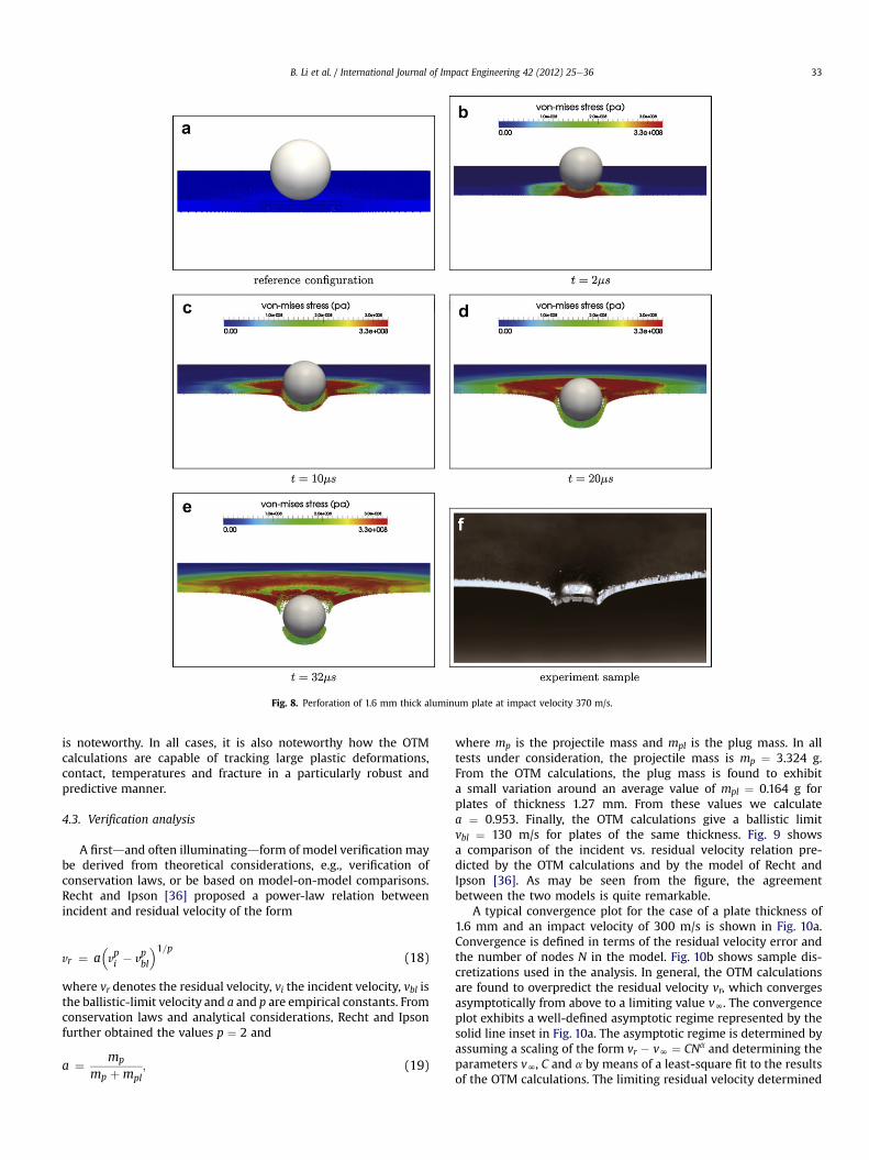
Fig. 8. Perforation of 1.6 mm thick aluminum plate at impact velocity 370 m/s.
B. Li et al. / International Journal of Impact Engineering 42 (2012) 25e36 33
is noteworthy. In all cases, it is also noteworthy how the OTMcalculations are capable of tracking large plastic deformations,contact, temperatures and fracture in a particularly robust andpredictive manner.
4.3. Verification analysis
A firstdand often illuminatingdform of model verification maybe derived from theoretical considerations, e.g., verification ofconservation laws, or be based on model-on-model comparisons.Recht and Ipson [36] proposed a power-law relation betweenincident and residual velocity of the form
vr ¼ a�vpi � v
pbl
�1=p(18)
where vr denotes the residual velocity, vi the incident velocity, vbl isthe ballistic-limit velocity and a and p are empirical constants. Fromconservation laws and analytical considerations, Recht and Ipsonfurther obtained the values p ¼ 2 and
a ¼ mp
mp þmpl; (19)
where mp is the projectile mass and mpl is the plug mass. In alltests under consideration, the projectile mass is mp ¼ 3.324 g.From the OTM calculations, the plug mass is found to exhibita small variation around an average value of mpl ¼ 0.164 g forplates of thickness 1.27 mm. From these values we calculatea ¼ 0.953. Finally, the OTM calculations give a ballistic limitvbl ¼ 130 m/s for plates of the same thickness. Fig. 9 showsa comparison of the incident vs. residual velocity relation pre-dicted by the OTM calculations and by the model of Recht andIpson [36]. As may be seen from the figure, the agreementbetween the two models is quite remarkable.
A typical convergence plot for the case of a plate thickness of1.6 mm and an impact velocity of 300 m/s is shown in Fig. 10a.Convergence is defined in terms of the residual velocity error andthe number of nodes N in the model. Fig. 10b shows sample dis-cretizations used in the analysis. In general, the OTM calculationsare found to overpredict the residual velocity vr, which convergesasymptotically from above to a limiting value vN. The convergenceplot exhibits a well-defined asymptotic regime represented by thesolid line inset in Fig. 10a. The asymptotic regime is determined byassuming a scaling of the form vr � vN ¼ CNa and determining theparameters vN, C and a by means of a least-square fit to the resultsof the OTM calculations. The limiting residual velocity determined

Fig. 9. Comparison of the residual velocity vr vs. incident velocity vi predicted by themodel of Recht and Ipson [36] and computed from the OTM calculations. The resultscorrespond to the case of Al6061-T6 aluminum plates of thickness 1.27 mm.
Fig. 10. a) Convergence plot of the residual velocity for 1.6 mm plates at an impactvelocity of 300 m/s. b) Sample discretizations (nodes) used in the convergenceanalysis.
B. Li et al. / International Journal of Impact Engineering 42 (2012) 25e3634
in this manner, vN ¼ 236 m/s, is in good agreement with the valueof the 239 m/s computed from the model of Recht and Ipson, [36].The computed rate of convergence, ae�1.19, is indicative of thelinear convergence of the residual velocity. Robust, low-orderconvergence is expecteddand indeed desirabledin problemsinvolving complex material behavior, including large-deformationcoupled thermoviscoplasticity, localized dissipation and failure.The particularly robust asymptotic convergence exhibited by theOTM method, in terms of a convergence indicator such as theresidual velocity that effectively convolves all sources of error in themodel, is noteworthy.
Fig. 11. Ballistic limit as a function of plate thickness in the range [0.8 mm, 1.6 mm].
4.4. Validation analysis
Finally, we present direct comparisons between predictions ofthe OTM method and experimental observations by way of vali-dation. Specifically, we choose the perforation area and the ballisticlimit as performance measures for purposes of validation. Valida-tion comparisons are carried out over the thickness range of[0.8 mm,1.6 mm] and velocity range of [100 m/s, 400 m/s]. Becausethe projectile/target system under consideration is highly over-matched, both the perforation area and the ballistic limit are highlyreproducible and exhibit low scatter, which greatly facilitatescomparisons between observations and calculations. In addition,the perforation area and the ballistic limit effectively probe allaspects of the model, including thermoviscoplasticity and fracture,over a broad range of operating conditions, from low to high impactvelocity.
Fig. 11 compares the ballistic limit observed experimentally anda linear least-square fit of the ballistic limit predicted by the OTMmethod as a function of plate thickness. As may be seen from thefigure, the agreement between the OTM predictions and experi-ment is excellent. Fig. 12 shows a comparison between theconventional impact velocity vs. perforation area ballistic curvepredicted by the OTM method and experimentally measured for

Fig. 12. Perforation area vs. velocity for aluminum plates impacted by steel sphericalprojectile.
B. Li et al. / International Journal of Impact Engineering 42 (2012) 25e36 35
two plate thicknesses of 1.27 mm and 1 mm. The curve show thefamiliar ‘cliff’ form, with an initial range of no-perforation up to theballistic limit, followed by a sharp upturndthe cliffdand a plateauwithin which the perforation area exhibits small variation. Again,the agreement between the predictions of the OTMmethod and theexperimental observations, both as regards the location of theballistic limit, the steep rise and the subsequent plateau, isexcellent.
5. Summary and concluding remarks
We have evaluated the performance of the Optimal Trans-portation Meshfree (OTM) method of Li et al. [21], suitablyextended to account for seizing contact and fracture, in applicationsinvolving terminal ballistics. The evaluation takes the form ofa conventional Verification and Validation (V&V) analysis. Insupport of the validation analysis, we have conducted tests
concerned with the normal impact of Aluminum alloy 6061-T6 thinplates by S2 tool steel spherical projectile over a range of platethicknesses and impact velocities. The tests were conducted atCaltech’s GALCIT gas-gun Plate-Impact Facility. In all cases, perfo-ration takes place by plugging. We find excellent agreementbetween measured and computed perforation areas and a ballisticlimits over a thickness range of [0.8mm,1.6mm] and velocity rangeof [100 m/s, 400 m/s]. Our verification analysis consists of model-on-model comparisons and an assessment of the convergence ofthe OTM method. Specifically, we find excellent agreementbetween the incident vs. residual velocities predicted by the OTMmethod and by the power-law relation of Recht and Ipson [36]. Wealso find robust linear convergence of the OTM method asmeasured in terms of residual velocity error vs. number of nodes.The study demonstrates the ability of the OTM method to reliablepredict ballistic performance in configurations involving complexmaterial behavior, including large plastic deformations, thermo-mechanical coupling and fracture.
Whereas the validation measures considered in the study,namely, the ballistic limit and perforation area, provide integralperformance measures that convolve all sources of approximationand error in themodel, a detailed analysis of each of such sources inturn is also of considerable value. Of particular concern is theaccuracy and fidelity of the eigenfracture scheme in complex situ-ations involving brittle and ductile fracture. Schmidt et al. [37] havesupplied rigorous proofs of convergence of the eigenfracturescheme to Griffith fracture in the particular case of linear elasticfracture mechanics. Schmidt et al. [37] also present numericalverification examples, also within the framework of linear elasticfracture mechanics. However, as employed here, the eigenfracturescheme of material point failure is applied under much moregeneral conditions of deformation, inelastic behavior, rate ofdeformation and temperature. Additional numerical verificationexamples that probe the performance of the eigenfracture schemeunder such conditions are presented in [34]. Overall, the eigen-fracture scheme is found to supply a robust and reliable approach tofracture that is free of the convergence problems that afflictconventional erosion methods.
The validation analysis presented in this paper relies ona direct comparison between predicted and measured perfor-mance measures and on an expert opinion regarding the goodnessof the comparison. A more quantitative methodology for assessingthe fidelity of a model is provided by methods of UncertaintyQuantification (UQ). These methods supply quantitative measures,e.g., in the form of a confidence factor, evaluated througha combination of simulation and experiment, of the probabilitythat a system will perform within a certain prespecified operatingrange. Uncertainty Quantification indirectly assesses the fidelityand accuracy of models, since inaccurate and unphysical modelsare likely to result in low-confidence predictions, even overregimes when the system is strongly expected to perform safely. AUQ analysis of the experimental configuration considered in thispaper based on the OTM method and on concentration-of-measure probability inequalities [26] may be found in [18]. Theanalysis again shows that OTM simulations lead to high-confidence predictions of lethality over a broad range of thick-nesses and impact velocities.
Acknowledgment
The authors gratefully acknowledge the support of the Depart-ment of Energy National Nuclear Security Administration underAward Number DE-FC52-08NA28613 through Caltech’s ASC/PSAAPCenter for the Predictive Modeling and Simulation of High EnergyDensity Dynamic Response of Materials.

B. Li et al. / International Journal of Impact Engineering 42 (2012) 25e3636
References
[1] Anderson Jr CE. An overview of the theory of hydrocodes. InternationalJournal of Impact Engineering 1987;5:33e59.
[2] Anderson JrCE, Bodner SR.Ballistic impact: the statusof analytical andnumericalmodelling. International Journal of Impact Engineering 1988;16:9e35.
[3] Arroyo M, Ortiz M. Local maximum-entropy approximation schemes:a seamless bridge between finite elements and meshfree methods. Interna-tional Journal for Numerical Methods in Engineering 2006;65:2167e202.
[4] Bardenhagen SG, Brackbill JU, Sulsky D. The material-point method forgranular materials. Computer Methods in Applied Mechanics and Engineering2000;187(3e4):529e41.
[5] Beissel SR, Gerlach CA, Holmquist TJ, Walker JD. A comparison of numericalmethods in the simulation of hypervelocity impact. In: Hiermaier S, editor.Proceedings of 11th hypervelocity impact symposium. Freiburg, Germany:Fraunhofer Verlag; 2010.
[6] Benson DJ. Computational methods in lagrangian and eulerian hydrocodes.Computer Methods in Applied Mechanics and Engineering 1992;99:235e394.
[7] Bentley JL, Friedman JH. Data structures for range searching. ComputingSurveys 1979;11:397e409.
[8] Bordasa S, Rabczukb T, Zi G. Three-dimensional crack initiation, propagation,branching and junction in non-linear materials by an extended meshfreemethod without asymptotic enrichment. Engineering Fracture Mechanics2008;75(5):943e60.
[9] Borvik T, Hopperstad OS, Pedersen KO. Quasi-brittle fracture during structuralimpact of aa7075-t651 aluminum plates. International Journal of ImpactEngineering 2008;37:537e51.
[10] Camacho GT, Ortiz M. Adaptive lagrangian modelling of ballistic penetrationof metallic targets. Computer Methods in Applied Mechanics and Engineering1997;142:269e301.
[11] Hirt CW, Amsden AA, Cook JL. An arbitrary lagrangian-eulerian computingmethod for all flow speeds. Journal of Computational Physics 1974;14:227e53.
[12] Hodowany J, Ravichandran G, Rosakis AJ, Rosakis P. Partition of plastic workinto heat and stored energy in metals. Experimental Mechanics 2000;40(2):113123.
[13] Johnson GR. Analysis of elastic-plastic impact involving severe distortions.Journal of Applied Mechanics 1976;98:439e44.
[14] Johnson GR, Stryk RA. User instruction for the 1990 version of the combined(1d,2d,3d) epic code. Technical Report DE-AC04e87AL-42550, DARPA; 1990.
[15] Stryk RA, Johnson GR. Eroding interface and improved tetrahedral elementalgorithms for high-velocity impact computations in three dimensions.International Journal of Impact Engineering 1987;5:411e21.
[16] Stryk RA, Johnson GR. Conversion of 3d distorted elements into meshlessparticles during dynamic deformation. International Journal of Impact Engi-neering 2003;28:947e66.
[17] Kane C, Marsden JE, Ortiz M, West M. Variational integrators and the new-mark algorithm for conservative and dissipative mechanical systems. Inter-national Journal for Numerical Methods in Engineering 2000;49(10):1295e325.
[18] Kidane AA, Lashgari A, Li B, McKerns M, Ortiz M, Owhadi H, Ravichandran G,Stalzer M, Sullivan TJ. Rigorous model-based uncertainty quantification withapplication to terminal ballistics, part i: Systems with controllable inputs andsmall scatter. Journal of the Mechanics and Physics of Solids, in press.
[19] Kimsey K, Randers-Pehrson G. Terminal effects codes. Technical ReportBRL-TR-3392. Maryland: U. S. Army Ballistic Research Laboratory; 1992.
[20] Lemonds J, Needleman A. Finite element analysis of shear localization in rateand temperature dependent solids. Mechanics of Materials 1986;5:339e61.
[21] Li B, Habbal F, Ortiz M. Optimal transportation meshfree approximationschemes for fluid and plastic flows. International Journal for NumericalMethods in Engineering 2010;83(12):1541e79.
[22] Li S, Qian D, Liu WK, Belytschko T. A meshfree contact-detection algorithm.Computer Methods in Applied Mechanics and Engineering 2001;190(24e25):3271e92.
[23] Libersky LD, Petschek AG. Lecture Notes in Physics, chapter Smooth ParticleHydrodynamics with strength of materials. Advances in the free-Lagrangemethod, vol. 395. Berlin: Springer-Verlag; 1991. 248e257.
[24] Liu MB, Liu GR. Smoothed particle hydrodynamics (sph): an overview andrecent developments. Archives of Computational Methods in Engineering2010;17(1):25e76.
[25] Lubliner J. Plasticity theory. Pearson Education; 1998.
[26] Lucas LJ, Owhadi H, Ortiz M. Rigorous verification, validation, uncertaintyquantification and certification through concentration-of-measure inequal-ities. Computer Methods in Applied Mechanics and Engineering 2008;197:4591e609.
[27] Marusich TD, Ortiz M. Modeling and simulation of high-speed machining.International Journal for Numerical Methods in Engineering 1995;38(21):3675e94.
[28] Matuska DA, Osborn JJ. Hull technical manual. Technical report. Florida, U.S.:Orlando Technology Inc; 1986.
[29] McGlaun JM. Cth user’s manual. Technical Report Technical Report SAND88-0523. California, U.S.: Sandia National Laboratories; 1988.
[30] McGlaun JM, Thompson SL, Elrick MG. Cth: a three-dimensional shockwavephysics code. International Journal of Impact Engineering 1990;10:351e60.
[31] Mehra V, Chaturvedi S. High velocity impact of metal sphere on thin metallicplates: a comparative smooth particle hydrodynamics study. Journal ofComputational Physics 2006;212(1):318e37.
[32] Ortiz M, Giannakopoulos AE. Crack propagation in monolithic ceramics undermixed mode loading. International Journal of Fracture 1990;44:233e58.
[33] Ortiz M, Stainier L. The variational formulation of viscoplastic constitutiveupdates. Computer Methods in Applied Mechanics and Engineering 1999;171:419e44.
[34] Pandolfi A, Li B, Ortiz M. Fracture by variational material point failure inoptimal transportation meshfree calculations. International Journal forNumerical Methods in Engineering, in press.
[35] Rabczuk Timon, Zi Goangseup. A meshfree method based on the local parti-tion of unity for cohesive cracks. Computational Mechanics 2007;39(6):743e60.
[36] Recht RF, Ipson TW. Ballistic perforation dynamics. Journal of AppliedMechanics 1963;30:384e90.
[37] Schmidt B, Fraternali F, Ortiz M. Eigenfracture: an eigendeformation approachto variational fracture. Multiscale Modeling and Simulation 2009;7:1237e66.
[38] Stainier L, Ortiz M. Study and validation of a variational theory of thermo-mechanical coupling in finite visco-plasticity. International Journal of Solidsand Structures 2010;47:705e15.
[39] Stellingwerf RF, Wingate CA. Impact modeling with smooth particle hydro-dynamics. International Journal of Impact Engineering 1993;14(1e4):707e18.
[40] Sulsky D, Chen Z, Schreyer HL. A particle method for history-dependentmaterials. Computer Methods in Applied Mechanics and Engineering 1994;118(12):179e96.
[41] Sulsky D, Chen Z, Schreyer HL. A particle method for history-dependentmaterials. Computer Methods in Applied Mechanics and Engineering 1994;118:179e86.
[42] Sulsky D, Schreyer HL. Axisymmetric form of the material point method withapplications to upsetting and taylor impact problems. Computer Methods inApplied Mechanics and Engineering 1996;139(1e4):409e29.
[43] Belytschko T, Lin. A three-dimensional impact-penetration algorithm witherosion. International Journal of Impact Engineering 1987;5:111e27.
[44] Whirley RG, Hallquist JO. Dyna-3d user manual. Technical Report TechnicalReport UCRL-MA-107254. California, U.S.: Lawrence Livermore NationalLaboratory; 1991.
[45] Wingate CA, Stellingwerf RF, Davidson RF, Burkett MW. Models of highvelocity impact phenomena. International Journal of Impact Engineering1993;14(1e4):819e30.
[46] Yadav S, Chichili DR, Ramesh KT. The mechanical response of a 6061-t6 al/al2o3 metal matrix composite at high rates of deformation. Acta Metallurgicaet Materialia 1995;43(12):4453e64.
[47] Yadav S, Repetto EA, Ravichandran G, Ortiz M. A computational study of theinfluence of thermal softening on ballistic penetration in metals. InternationalJournal of Impact Engineering 2001;25(8):787e803.
[48] Yang Q, Stainier L, Ortiz M. A variational formulation of the coupled thermo-mechanical boundary-value problem for general dissipative solids. Journal ofthe Mechanics and Physics of Solids 2006;54:401e24.
[49] Zhang X, Sze KY, Ma S. An explicit material point finite element method forhyper-velocity impact. International Journal for Numerical Methods in Engi-neering 2006;66(4):689e706.
[50] Zhou CE, Liu GR, Lou KY. Three-dimensional penetration simulation usingsmoothed particle hydrodynamics. International Journal of ComputationalMethods 2007;4(4):671e91.
[51] Zukas J. High velocity impact dynamics. Chapter Survey of Computer Codes forImpact Simulation. New York: Wiley; 1990. pp. 593e714.