International Journal of Heat and Mass...
9
Superadiabatic radiant porous burner with preheater and radiation corridors Vahid Vandadi a , Chanwoo Park a,⇑ , Massoud Kaviany b a Department of Mechanical Engineering, University of Nevada, Reno, NV 89557-0312, USA b Department of Mechanical Engineering, University of Michigan, Ann Arbor, MI 48105, USA article info Article history: Received 12 April 2013 Accepted 20 April 2013 Keywords: Superadiabatic Radiant burner Porous media Heat recirculation Preheating Pre-mixed Lean combustion abstract The current efficiency of monolithic (including two-layer) radiant porous burners is less than 25% and here we introduce a novel structure for effective preheating and radiation routing to increase the effi- ciency. This recovers the flue gas heat to increase the inlet air temperature and raises the flame temper- ature locally above the adiabatic temperature (superadiabatic flame) for the fuel-lean conditions. The heat from the superadiabatic region is then extracted and conducted through embedded, high-thermal conductivity radiation corridors and is radiated, at a higher temperature than the flue gas, to the target. The analyses of local thermal non-equilibrium among the gas phase, two-layer porous solid, preheating heat exchanger, and radiant corridor are presented for the zeroth-order reaction of premixed methane/ air. Radiant burner efficiency over 45% is predicted. Ó 2013 Elsevier Ltd. All rights reserved. 1. Introduction Porous burners have been extensively studied because of their low pollutant emissions and fuel flexibility. The idea of the porous burner was initiated to find a simple way to produce a superadia- batic flame by inserting a high conductivity porous solid into the flame region to recuperate the heat of the hot downstream gas to cold upstream gas through the solid. Since the porous burners internally recirculate the combustion heat through convection, so- lid conduction, and radiation to preheat the incoming cold gas flow; they can operate at lower equivalence ratios of fuel/air mix- ture at higher flame speeds than the laminar flame. The one-layer porous burners and multiple layers were studied by various researchers [1–5]. The porous burner made of three lay- ers was numerically analyzed by Yoshizawa et al. [1]. In the study, the reaction was assumed to entirely take place in the middle layer. They reported that the temperature profiles were greatly af- fected by the interstitial heat transfer coefficient and radiation properties such as absorption coefficient, and optical thickness of the porous media. An experimental investigation was presented by Younis and Viskanta [6] to characterize the heat transfer be- tween the gas and solid phases in a porous medium. A heat transfer correlation for different ceramic foams was presented. The radiative heat transfer in the porous burners plays an important role in the recuperation of the combustion heat [7– 11]. The effect of the solid thermal conductivity on the radiative heat transfer in packed beds was reported by Singh and Kaviany [7]. It was reported that the radiant conductivity was strongly influenced by the thermal conductivity of the solid phase and the emissivity of the particles. It was also reported that the sensitivity of the radiant conductivity with respect to the porosity was not significant. The local volume averaged method used in various studies of the combustion in porous media [12–15], is the two-medium treatment which allows a non-thermal equilibrium between the solid and gas phases. Sahraoui and Kaviany [12] presented a comparison of the direct simulation and volume averaged treatment of the premixed flame in a porous medium. In recent years the porous burner using two-layer porous media with distinctively different thermophysical properties has been studied by many researchers to anchor the flame at the interface between two porous layers [16,17]. An experimental investigation on stabilization of flame using a two-layer porous burner made of randomly packed spherical alumina pellets was performed by Bub- novich et al. [16]. The results of the temperature profiles and pol- lutant emissions were reported for the equivalence ratios of 0.6 and 0.7 of methane/air mixture. Several studies have utilized various burner designs to recover the heat loss of the exhaust gas to preheat the incoming fuel/air mixture [18–21]. The preheating effect on superadiabatic combus- tion of propane/air mixture was studied by Huang et al. [18]. They 0017-9310/$ - see front matter Ó 2013 Elsevier Ltd. All rights reserved. http://dx.doi.org/10.1016/j.ijheatmasstransfer.2013.04.054 ⇑ Corresponding author. Address: Department of Mechanical Engineering, University of Nevada, Reno, 1664 N. Virginia Street, Reno, NV 89557-0312, USA. Tel.: +1 775 682 6301; fax: +1 775 784 1701. E-mail address: [email protected] (C. Park). International Journal of Heat and Mass Transfer 64 (2013) 680–688 Contents lists available at SciVerse ScienceDirect International Journal of Heat and Mass Transfer journal homepage: www.elsevier.com/locate/ijhmt
Transcript of International Journal of Heat and Mass...

International Journal of Heat and Mass Transfer 64 (2013) 680–688
Contents lists available at SciVerse ScienceDirect
International Journal of Heat and Mass Transfer
journal homepage: www.elsevier .com/locate / i jhmt
Superadiabatic radiant porous burner with preheater and radiationcorridors
0017-9310/$ - see front matter � 2013 Elsevier Ltd. All rights reserved.http://dx.doi.org/10.1016/j.ijheatmasstransfer.2013.04.054
⇑ Corresponding author. Address: Department of Mechanical Engineering,University of Nevada, Reno, 1664 N. Virginia Street, Reno, NV 89557-0312, USA.Tel.: +1 775 682 6301; fax: +1 775 784 1701.
E-mail address: [email protected] (C. Park).
Vahid Vandadi a, Chanwoo Park a,⇑, Massoud Kaviany b
a Department of Mechanical Engineering, University of Nevada, Reno, NV 89557-0312, USAb Department of Mechanical Engineering, University of Michigan, Ann Arbor, MI 48105, USA
a r t i c l e i n f o
Article history:Received 12 April 2013Accepted 20 April 2013
Keywords:SuperadiabaticRadiant burnerPorous mediaHeat recirculationPreheatingPre-mixedLean combustion
a b s t r a c t
The current efficiency of monolithic (including two-layer) radiant porous burners is less than 25% andhere we introduce a novel structure for effective preheating and radiation routing to increase the effi-ciency. This recovers the flue gas heat to increase the inlet air temperature and raises the flame temper-ature locally above the adiabatic temperature (superadiabatic flame) for the fuel-lean conditions. Theheat from the superadiabatic region is then extracted and conducted through embedded, high-thermalconductivity radiation corridors and is radiated, at a higher temperature than the flue gas, to the target.The analyses of local thermal non-equilibrium among the gas phase, two-layer porous solid, preheatingheat exchanger, and radiant corridor are presented for the zeroth-order reaction of premixed methane/air. Radiant burner efficiency over 45% is predicted.
� 2013 Elsevier Ltd. All rights reserved.
1. Introduction
Porous burners have been extensively studied because of theirlow pollutant emissions and fuel flexibility. The idea of the porousburner was initiated to find a simple way to produce a superadia-batic flame by inserting a high conductivity porous solid into theflame region to recuperate the heat of the hot downstream gas tocold upstream gas through the solid. Since the porous burnersinternally recirculate the combustion heat through convection, so-lid conduction, and radiation to preheat the incoming cold gasflow; they can operate at lower equivalence ratios of fuel/air mix-ture at higher flame speeds than the laminar flame.
The one-layer porous burners and multiple layers were studiedby various researchers [1–5]. The porous burner made of three lay-ers was numerically analyzed by Yoshizawa et al. [1]. In the study,the reaction was assumed to entirely take place in the middlelayer. They reported that the temperature profiles were greatly af-fected by the interstitial heat transfer coefficient and radiationproperties such as absorption coefficient, and optical thickness ofthe porous media. An experimental investigation was presentedby Younis and Viskanta [6] to characterize the heat transfer be-tween the gas and solid phases in a porous medium. A heat transfercorrelation for different ceramic foams was presented.
The radiative heat transfer in the porous burners plays animportant role in the recuperation of the combustion heat [7–11]. The effect of the solid thermal conductivity on the radiativeheat transfer in packed beds was reported by Singh and Kaviany[7]. It was reported that the radiant conductivity was stronglyinfluenced by the thermal conductivity of the solid phase and theemissivity of the particles. It was also reported that the sensitivityof the radiant conductivity with respect to the porosity was notsignificant. The local volume averaged method used in variousstudies of the combustion in porous media [12–15], is thetwo-medium treatment which allows a non-thermal equilibriumbetween the solid and gas phases. Sahraoui and Kaviany [12]presented a comparison of the direct simulation and volumeaveraged treatment of the premixed flame in a porous medium.
In recent years the porous burner using two-layer porous mediawith distinctively different thermophysical properties has beenstudied by many researchers to anchor the flame at the interfacebetween two porous layers [16,17]. An experimental investigationon stabilization of flame using a two-layer porous burner made ofrandomly packed spherical alumina pellets was performed by Bub-novich et al. [16]. The results of the temperature profiles and pol-lutant emissions were reported for the equivalence ratios of 0.6and 0.7 of methane/air mixture.
Several studies have utilized various burner designs to recoverthe heat loss of the exhaust gas to preheat the incoming fuel/airmixture [18–21]. The preheating effect on superadiabatic combus-tion of propane/air mixture was studied by Huang et al. [18]. They

Nomenclature
A surface area (m2)Ags/V specific volume (1/m), e/Dp
ar pre-factor of combustion reaction (1/s)C coefficient or thermal capacity (J/K)cp specific heat of gas mixture (J/kg K)Cr thermal capacity ratio, Cmin/Cmax
Dg species diffusivity (m2/s)D diameter (m)Dd
xx thermal diffusivity due to dispersion (m2/s)
Ddmxx
species diffusivity due to dispersion (m2/s)H height (m)hh heat transfer coefficient of the hot stream of the pre-
heater (W/m2 K)I modified Bessel, first kindK modified Bessel, second kindk thermal conductivity (W/m K)L length (m)Le Lewis number,(kg,e/(qcp)g)/Dg,e
MW molecular weight (kg/kmol)_m mass flow rate (kg/s)
NuD,p Nusselt number, hv D2p=kg
N number of componentsNTU number of transfer unit_ng;r;F rate of consumption of fuel (kg/m3 s)P pressure (Pa)Pe Peclet number, qgcpeugDp/kg
Pr Prandtl numberQ rate of energy transfer (W)q heat flux (W/m2)R radius (m)r radial coordinate (m)Re Reynolds number, qgeugDp/lRg universal gas constant (J/kmol K)T temperature (K)U overall heat transfer coefficient (W/m2 K)u velocity (m/s)XF flame location (m)x coordinate (m)Y mass fraction of speciesy coordinate (m)W width (m)wf half thickness of fin (m)
Greek lettersag thermal diffusivity (m2/s)DEa activation energy (J/kmol)Dhr,F standard heat of reaction (J/kg)DL spacing of adjacent nodes (m)e porosity or effectivenesser emissivityg thermal efficiency (%)l viscosity (Pa s)q density (kg/m3)
re extinction coefficient (1/m)rPH ratio of free flow area and front area in preheaterrSB Stefan–Boltzmann constant (W/m2 K4)/ equivalence ratio, (qF,g/qg)/(qF,g/qg)stoich
Subscriptsa actual or activationad advection or adiabaticair airave averageb base of finc cold streamcb combustioncd conductioncv convectione effectiveF fuel or flamef fins of radiation rodsg gas phasegs gas to solidh hot stream or hydraulici x-directional nodal indexin inletins insulationj y-directional nodal indexmax maximummin minimumo out or oxygenPH preheaterPM porous mediump pore or particleRR radiation rodr radiation or reactionrad radiationrf rod and finrs radiating surfaces solid phasestoich stoichiometrict target or totaltu preheater tubev volumetricxx x-directional
Superscriptsd dispersionm exponent or coefficient⁄ normalized
Others1 ambient or surrounding
V. Vandadi et al. / International Journal of Heat and Mass Transfer 64 (2013) 680–688 681
reported that the preheating had a great influence on ignition andextinction of flame. It was also shown that the decrease of the pre-heating equivalence ratio would increase the critical preheatingenergy to sustain a stable combustion mode.
In this paper, a novel porous radiant burner using a preheaterand radiation corridors for high efficiency radiant output, is ana-lyzed and the results from the numerical analysis using a zeroth-order combustion reaction model for methane/air mixture andnon-thermal equilibrium formulation are presented.
2. Numerical analysis
The radiant porous burner considered for a numerical analysisis shown in Fig. 1(a) and (b) and consists of two-layer porous med-ia (PM1, and PM2), a preheater (PH) and radiation rods (RR). Thecold inlet air is heated by the preheater using hot flue gas fromthe porous burner. The preheated air is then mixed with the coldgaseous fuel flow in the upstream porous medium (PM1) with afine porous structure. The downstream porous medium (PM2) with

Fig. 1. (a) Schematic of the superadiabatic radiant porous burner with two-layerporous media, a preheater and radiation rods showing gas flows and heat transfers,(b) side view of computational domain, (c) schematic diagram of the superadiabaticradiant burner system showing heat transfer, mass flow and key temperatures.
Table 1Thermophysical properties and dimensions of the superadiabatic radiant burner andcoefficients of zeroth-order reaction model.
Burner dimensions
Height, H (cm) 2.54Length, L (cm) 12.1Width, W (cm) 30.0
Porous media PM1 PM2
Length, LPM (cm) 3.6 2.4Particle diameter, DP (mm) 0.29 1.52Porosity, e 0.835 0.87Emissivity, er 1 1Thermal conductivity, ks (W/m K) 0.2 0.1C 0.638 0.146m 0.42 0.96
Radiation rod and fins of radiation rodMaterial Carbon steel LRR (cm) 8.5Melting point (K) 1750–1850 Nf 7kRR (W/m K) 50 Rf (cm) 1.0kins (W/m K) 0.05 Rb (mm) 2.0RRR (cm) 0.7 Rrs (cm) 1.2Rins (cm) 0.75 wf (mm) 0.5
PreheaterLPH (cm) 6.1Tube radius, Rtu (mm) 5.1Fin pitch (m�1) 314Flow passage hydraulic diameter, Dh (mm) 3.63Fin thickness (mm) 0.33Free flow area/front area, rPH 0.534Heat transfer area/total volume (m2/m3) 587Fin area/total area 0.913Number of preheater tubes, Ntu 3
Fuel, methane (CH4)MW (kg/kmol) 16(qF,g /qg)stoich 1/18.12�Dhr,F (J/kg) (HHV) 55.53 � 106
Reaction model coefficientsar (1/s) 4.8 � 108
DEa (J/kmol) 1.3 � 108
682 V. Vandadi et al. / International Journal of Heat and Mass Transfer 64 (2013) 680–688
a coarse porous structure serves as a flame holder to stabilizethe flame where the fins of the radiation rods are located(Fig. 1(c)).
The heat transfers and mass flow in the superadiabatic radi-ant burner system are shown in Fig. 1(c). The combustion heatis extracted by the fins of the radiation rods (RR) and then con-ducted through the radiation rods to the radiating surfaces. Theradiation rods made of a metallic material provide highly con-ducting paths from the flame to the radiating surfaces. Theradiation rods are assumed to be coated with a low thermalconductivity material (thermal insulator) to reduce the heat lossto the colder surrounding flue gas being cooled by the pre-heater. Therefore, the combustion heat is efficiently transferredto the radiating surface at higher temperatures than the exitingflue gas temperature. As a result, the superadiabatic radiantburner can achieve higher thermal efficiency than the conven-tional burner.
2.1. Porous burner
The porous burner consisting of upstream (PM1) and down-stream (PM2) porous media as shown in Fig. 1(b) is analyzed usingnon-thermal equilibrium formulation. The thermophysical proper-ties and dimensions of the burner system are presented in Table 1.
The conservation equations of mass, gas species, and energy forgas and solid phases of the porous burner are given by
@
@xðeqgugÞ ¼ 0; ð1Þ
eqgug@YF;g
@x¼ @
@xqgDg;e
@YF;g
@x
� �þ e _ng;r;F ; ð2Þ
eðqcpuÞg@Tg
@x¼ @
@xkg;e
@Tg
@x
� �þ NuD;p
kg
Dp
Ags
V
� �ðTs � TgÞ
þ e _ng;r;FDhr;F ; ð3Þ
0 ¼ @
@xks;e
@Ts
@x
� �þ NuD;p
kg
Dp
Ags
V
� �ðTg � TsÞ: ð4Þ
The continuity, species and energy equations are discretized usingfinite volume method over the computational domain of the porousmedia (PM1 and PM2).
The density of the gas flow is computed from the ideal gas law,in which the properties of the gas mixture are considered and is gi-ven by

Table 2Coefficients of the polynomial curvefit equations for the specific heat capacity andthermal conductivity of the gas phase [25].
c1T4 + c2T3 + c3T2 + c4T + c5
cp,g kg
c1 1.3958 � 10�10 2.930 � 10�14
c2 �6.5412 � 10�7 �1.3208 � 10�10
c3 0.0010395 2.0396 � 10�7
c4 �0.44833 �6.4181 � 10�5
c5 1066.2 0.033158
V. Vandadi et al. / International Journal of Heat and Mass Transfer 64 (2013) 680–688 683
qg ¼Pg
RgTg: ð5Þ
The interstitial convective heat transfer is modeled by the volumet-ric Nusselt number [6] and is given by
NuD;p ¼ CRem; ð6Þ
where C and m values are listed in Table 1. Re is the Reynolds num-ber of the gas flow in the porous media and is given by
Re ¼ eqgugDp=l: ð7Þ
The specific volume of the porous media is given by
Ags=V ¼ e=Dp: ð8Þ
The effective thermal conductivity of the gas phase consists of dif-fusion and dispersion terms and is given by
kg;e ¼ ekg þ ðqcpÞgDdxx; ð9Þ
where the thermal diffusivity [22] is given by
Ddxx ¼ 0:5agPe; ð10Þ
and the Peclet number is given by
Pe ¼ qgcpeugDp=kg : ð11Þ
The Lewis number is assumed to be unity as below,
Le ¼kg;e=ðqcpÞg
Dg;e¼ 1; ð12Þ
where the mass diffusivity is given by
Dg;e ¼ eDg þ Ddmxx: ð13Þ
The effective thermal conductivity of the solid phase consists ofthe volume-averaged thermal conductivity and the radiative ther-mal conductivity of the solid phase and is given by
ks;e ¼ ð1� eÞks þ eks;r; ð14Þ
where the radiative thermal conductivity is given by
ks;r ¼16errSBT3
s
3re: ð15Þ
The zeroth-order reaction rate is used to model the combustion offuel/air mixture and is given by
_ng;r;F ¼ �are�DEa=Rg Tg ; ð16Þ
where the coefficients of the combustion model (ar and DEa) forpremixed methane/air flow are listed in Table 1.
Since the specific heat capacity and thermal conductivity of thegas phase significantly vary with temperature, they are given asthe functions of temperature by fourth-order polynomial equa-tions listed in Table 2.
The perfect mixing of the preheated air and fuel is assumed atthe inlet of the burner. The equivalence ratio of the fuel/air mixtureis defined as / ¼ ðqF;g=qgÞ=ðqF;g=qgÞstoich: The velocity of the fuel/air
mixture ðugÞ, entering the burner, is calculated by the mass conser-vation equation which is given by
qgugHW 1� /ðqF;g=qgÞstoich
h i¼ NtuqairuairpR2
tu ð17Þ
The boundary conditions for the energy and species equations arepresented below.
Inlet (x = 0):
�ð1� eÞks@Ts
@x¼ errSBðT4
s � T4gÞ; ð18Þ
Tg ¼ Tg;in; ð19Þ
YF;g ¼ /qF;g
qg
!stoich
: ð20Þ
Outlet (x = LPM):
�ð1� eÞks@Ts
@x¼ errSBðT4
s � T4PH;aveÞ; ð21Þ
@Tg
@x¼ 0; ð22Þ
@YF;g
@x¼ 0: ð23Þ
It is assumed that the porous burner exchanges radiation heatat the outlet with the preheater at its average temperature. Allthe properties used for the numerical analysis are evaluated basedon the mass-averaged mixture of air and fuel.
The governing equations of the porous burner are discretizedusing uniform grid nodes. The equations are solved by enough iter-ation until a convergence is achieved. The continuity equation ofthe gas flow, Eq. (1) is directly used to calculate the velocity at eachnode. The density of the gas flow is computed by ideal gas law. Theinitial temperature profiles for gas and solid phases with their peaktemperatures at the interface of the upstream and downstreamporous media are set to ignite the flame. Note that all propertiesare smoothed near the interface of two porous media to avoidnumerical errors due to discontinuous properties. But the porosityof the porous media was allowed to vary across the interface (Eq.(4)).
2.2. Radiation rods and preheater
The radiation rods and preheater analyzed in this study areshown in Figs. 1(b) and 2. The radiation rod consists of (i) the radialfins located close to the interface of the two layers of the porousmedia, (ii) a stem and (iii) a radiating disk. The thermophysicalproperties and dimensions of the radiation rod and preheater arelisted in Table 1.
The radial fins of the radiation rods are modeled by consideringthe convection and conduction heat transfers [23]. The equationsand boundary conditions are given by
ddr
rdTdr
� �¼ rNuD;p
wf ðAgs=VÞD2p
ðT � TgÞ; ð24Þ
T ¼ Tb at r ¼ Rb; ð25Þ
dTdr¼ 0 at r ¼ Rf ; ð26Þ
where wf is the half thickness of each fin.The convection heat transfer is considered for the radial fins
with an insulated tip boundary condition. The stem of the radiationrod is divided to as many nodes as aligned with the preheater tubes
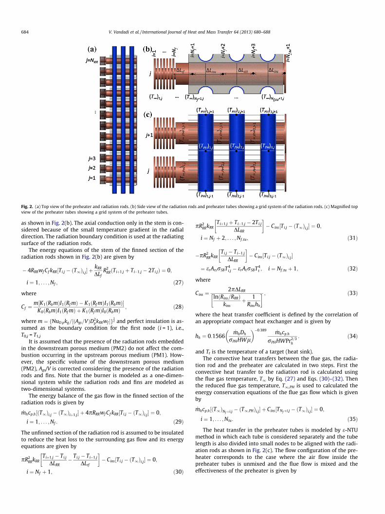
Fig. 2. (a) Top view of the preheater and radiation rods. (b) Side view of the radiation rods and preheater tubes showing a grid system of the radiation rods. (c) Magnified topview of the preheater tubes showing a grid system of the preheater tubes.
684 V. Vandadi et al. / International Journal of Heat and Mass Transfer 64 (2013) 680–688
as shown in Fig. 2(b). The axial conduction only in the stem is con-sidered because of the small temperature gradient in the radialdirection. The radiation boundary condition is used at the radiatingsurface of the radiation rods.
The energy equations of the stem of the finned section of theradiation rods shown in Fig. 2(b) are given by
� 4RRRwf Cf kRR½Ti;j � ðT1Þi;j� þkRR
DLfR2
RRðTiþ1;j þ Ti�1;j � 2Ti;jÞ ¼ 0;
i ¼ 1; . . . ;Nf ; ð27Þ
where
Cf ¼m½K1ðRbmÞI1ðRf mÞ � K1ðRf mÞI1ðRbmÞ�
K0ðRbmÞI1ðRf mÞ þ K1ðRf mÞI0ðRbmÞ ; ð28Þ
where m ¼ fNuD;pkg=½ðAgs=VÞD2pkRRwf �g
12 and perfect insulation is as-
sumed as the boundary condition for the first node (i = 1), i.e.,T0,j = T1,j
It is assumed that the presence of the radiation rods embeddedin the downstream porous medium (PM2) do not affect the com-bustion occurring in the upstream porous medium (PM1). How-ever, the specific volume of the downstream porous medium(PM2), Ags/V is corrected considering the presence of the radiationrods and fins. Note that the burner is modeled as a one-dimen-sional system while the radiation rods and fins are modeled astwo-dimensional systems.
The energy balance of the gas flow in the finned section of theradiation rods is given by
_mhcp;h½ðT1Þi;j � ðT1Þiþ1;j� þ 4pRRRwf Cf kRR½Ti;j � ðT1Þi;j� ¼ 0;
i ¼ 1; . . . ;Nf : ð29Þ
The unfinned section of the radiation rod is assumed to be insulatedto reduce the heat loss to the surrounding gas flow and its energyequations are given by
pR2RRkRR
Tiþ1;j � Ti;j
DLRR� Ti;j � Ti�1;j
DLrf
� �� Cins½Ti;j � ðT1Þi;j� ¼ 0;
i ¼ Nf þ 1; ð30Þ
pR2RRkRR
Tiþ1;j þ Ti�1;j � 2Ti;j
DLRR
� �� Cins½Ti;j � ðT1Þi;j� ¼ 0;
i ¼ Nf þ 2; . . . ;Nf ;tu; ð31Þ
�pR2RRkRR
Ti;j � Ti�1;j
DLRR
� �� Cins½Ti;j � ðT1Þi;j�
¼ erArsrSBT4i;j � erAtrSBT4
t ; i ¼ Nf ;tu þ 1; ð32Þ
where
Cins ¼2pDLRR
lnðRins=RRRÞkins
þ 1Rinshh
� � ; ð33Þ
where the heat transfer coefficient is defined by the correlation ofan appropriate compact heat exchanger and is given by
hh ¼ 0:1566_mhDh
rPHHWl
� ��0:389 _mhcp;h
rPHHWPr2=3h
: ð34Þ
and Tt is the temperature of a target (heat sink).The convective heat transfers between the flue gas, the radia-
tion rod and the preheater are calculated in two steps. First theconvective heat transfer to the radiation rod is calculated usingthe flue gas temperature, T1 by Eq. (27) and Eqs. (30)–(32). Thenthe reduced flue gas temperature, T1,PH is used to calculated theenergy conservation equations of the flue gas flow which is givenby
_mhcp;h½ðT1ÞNfþi;j � ðT1;PHÞi;j� þ Cins½TNfþi;j � ðT1Þi;j� ¼ 0;
i ¼ 1; . . . ;Ntu: ð35Þ
The heat transfer in the preheater tubes is modeled by e-NTUmethod in which each tube is considered separately and the tubelength is also divided into small nodes to be aligned with the radi-ation rods as shown in Fig. 2(c). The flow configuration of the pre-heater corresponds to the case where the air flow inside thepreheater tubes is unmixed and the flue flow is mixed and theeffectiveness of the preheater is given by

Table 3Stable range of the operation of conventional porous burner.
U 0.60 0.65 0.7 0.75 0.8
ug,max (cm/s) 11 14 33 47 63ug,min (cm/s) 36 50 74 89 105ug,max � ug,min 25 36 41 42 42
Experimental results from Khanna [24]ug,max (cm/s) 15 15 32 50 70ug,min (cm/s) 33 48 63 80 93ug,max � ug,min 18 33 31 30 23
V. Vandadi et al. / International Journal of Heat and Mass Transfer 64 (2013) 680–688 685
e ¼ 1� expfCr½expð�NTUÞ � 1�gCr
; ð36Þ
where NTU is calculated by
NTU ¼ UACmin
; ð37Þ
where U is the overall heat transfer coefficient of the preheaterincluding the internal and external convective heat transfer coeffi-cients. Each node of the preheater tube is solved to find the outletair temperature of the node. The outlet air temperature is used asthe inlet air temperature for the next adjacent node of the preheatertube. The air temperature in the preheater is calculated at theboundary of two adjacent nodes and is given by
Cc½ðTPHÞi;j � ðTPHÞiþ1;j� ¼ eCmin½ðT1;PHÞi;j � ðT1;PHÞi;j�1�; j ¼ 1; . . . ;NRR:
ð38Þ
The temperature of the flue gas flow from each node, which isused as the ambient temperature for the radiation rods, is given by
Ch½ðT1;PHÞi;j � ðT1Þiþ1;j� ¼ eCmin½ðT1;PHÞi;j � ðTPHÞi;j�1�; j ¼ 1; . . . ;NRR:
ð39Þ
The algebraic equations governing the radiation rods and pre-heater are solved using the IMSL library.
The thermal efficiency of the burner is defined as the ratio of theradiation output to the target and the combustion heat and is de-fined by
g ¼ Q rs
Q cb; ð40Þ
where the radiation output is given by
Q rs ¼XðerArsrSBT4
rs � erAtrSBT4t Þ ð41Þ
and the combustion heat is given by
Q cb ¼ /a
qF;g
qg
!stoich
qgugHWDhr;F : ð42Þ
The convective heat transfer (Q RR in Fig. 1(c)) between the radi-ation rods and the gas flow is calculated using the gas temperaturebased on the equivalence ratio ð/Þ. The gas temperature is lowerthan the actual gas temperature based on the actual equivalenceratio (/a), which allows a conservative calculation of the heatextraction by the radiation rods. The equivalence ratio based onthe actual fuel supply is calculated by
/a ¼/
1� g: ð43Þ
Fig. 3. (a) Temperature profiles of the superadiabatic burner. (b) Variations of thetemperatures for the gas and solid phases, concentration of species and reactionrate in the porous media of the superadiabatic burner near the flame location(Ua = 0.5, U = 0.32, uair = 6 cm/s).
3. Results and discussion
3.1. Heat recirculation of superadiabatic radiant burner
The results of the numerical analysis for the conventionaltwo-layer porous burner was compared and validated with the
experimental results of Khanna [24]. It was found from the resultsof the numerical analysis that the flame speeds are in good agree-ment with the experimental results in Table 3.
The superadiabatic radiant burner with two-layer porous bur-ner (PM1 and PM2), a preheater (PH) and radiation rods (RR) wasanalyzed. The temperature profiles of the superadiabatic radiantburner are depicted in Fig. 3(a). The conventional burner withoutpreheater uses the inlet air at ambient temperature, while the sup-eradiabatic burner uses an inlet air at higher temperatures becauseof the external heat recovery (preheating), and thus, expands thefuel lean limit of flammability. For the superadiabatic burner, theradiation rods made of a high thermal conductivity material areused to transfer the combustion heat efficiently from the flameto the radiating surface with a small temperature drop.
As a result of the preheating and separate heat transfer throughthe radiation rods, the temperature of the radiating surface isgreater than the flue gas temperature and close to the adiabatictemperature. It is shown in Fig. 3(a) that, the radiating surface tem-perature is 81 K greater than that of the exit flue gas resulting inhigher radiation efficiency. Note that the temperature at the inter-face of the porous media (between PM1 and PM2) was used as sur-rounding gas temperature of the fins of the radiation rods for the
686 V. Vandadi et al. / International Journal of Heat and Mass Transfer 64 (2013) 680–688
convective heat transfer which is a more conservative way for theheat transfer calculation.
The temperature and gas species profiles in the upstream por-ous medium (PM1) near the flame location are magnified inFig. 3(b). As shown in the figure, the gas temperature is slightlylower than the solid temperature near the inlet and then the gastemperature is higher than the solid temperature close to theflame. The heat transfer from the hotter solid to the incoming coldgas flow elucidates the internal heat recirculation which is in factthe heat transfer from the flame to the cold gas flow by solid ma-trix and is responsible for fuel-lean and superadiabatic combustionin the conventional porous burner [7,10,19]. After the flame, thethermal equilibrium between the gas and solid phases is quicklyachieved due to the interfacial convection heat transfer. It is alsoshown in Fig. 3(b) that the fuel is completely depleted by the com-bustion, but the excess oxygen is still left under fuel-leanconditions.
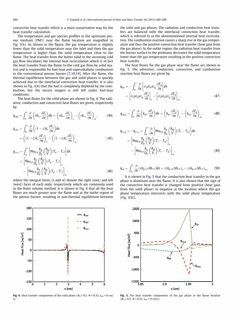
The heat fluxes for the solid phase are shown in Fig. 4. The radi-ative, conductive and convective heat fluxes are given, respectivelyby
qrad ¼Z e
w
@
@xeks;r
@Ts
@x
� �dx ¼ eks;r
@Ts
@x
� �e
� eks;r@Ts
@x
� �w
; ð44Þ
qcd;s ¼Z e
w
@
@xð1� eÞks
@Ts
@x
� �dx
¼ ð1� eÞks@Ts
@x
� �e
� ð1� eÞks@Ts
@x
� �w
; ð45Þ
qcv;s ¼Z e
wNuD;p
kg
Dp
Ags
V
� �ðTg � TsÞ
� �dx
¼ NuD;pkg
Dp
Ags
V
� �ðTg � TsÞ
� �e
� NuD;pkg
Dp
Ags
V
� �ðTg � TsÞ
� �w
; ð46Þ
where the integral limits (e and w) denote the right (east) and left(west) faces of each node, respectively which are commonly usedin the finite volume method. It is shown in Fig. 4 that all the heatfluxes are much greater near the flame and at the outlet region ofthe porous burner, resulting in non-thermal equilibrium between
Fig. 4. Heat transfer components of the solid phase (Ua = 0.5, U = 0.32, uair = 6 cm/s).
the solid and gas phases. The radiation and conduction heat trans-fers are balanced with the interfacial convection heat transfer,which is referred to as the aforementioned internal heat recircula-tion. The combustion reaction causes a sharp rise in the gas temper-ature and thus the positive convection heat transfer (heat gain fromthe gas phase). In the outlet region, the radiation heat transfer fromthe burner surface to the preheater decreases the solid temperaturelower than the gas temperature resulting in the positive convectiveheat transfer.
The heat fluxes for the gas phase near the flame are shown inFig. 5. The advective, conductive, convective, and combustionreaction heat fluxes are given by
qad ¼ �Z e
w
@
@xeðqcpuÞg
@Tg
@x
� �dx
¼ eðqcpuÞg@Tg
@x
� �e
� eðqcpuÞg@Tg
@x
� �w
; ð47Þ
qcd;g ¼Z e
w
@
@xkg;e
@Tg
@x
� �dx ¼ kg;e
@Tg
@x
� �e
� kg;e@Tg
@x
� �w
; ð48Þ
qcv;g ¼ �qcv;s ¼Z e
w
@
@xNuD;p
kg
Dp
Ags
V
� �ðTs � TgÞ
� �dx
¼ NuD;pkg
Dp
Ags
V
� �ðTs � TgÞ
� �e
� NuD;pkg
Dp
Ags
V
� �ðTs � TgÞ
� �w
; ð49Þ
qcb ¼Z e
w
@
@xðe _ng;r;FDhr;FÞdx ¼ ðe _ng;r;FDhr;FÞe � ðe _ng;r;FDhr;FÞw: ð50Þ
It is shown in Fig. 5 that the conduction heat transfer in the gasphase is dominant near the flame. It is also shown that the sign ofthe convective heat transfer is changed from positive (heat gainfrom the solid phase) to negative at the location where the gasphase temperature intersects with the solid phase temperature(Fig. 3(b)).
Fig. 5. The heat transfer components of the gas phase at the flame location(Ua = 0.5, U = 0.32, uair = 6 cm/s).

V. Vandadi et al. / International Journal of Heat and Mass Transfer 64 (2013) 680–688 687
3.2. Preheating of superadiabatic radient burner
The superadiabatic radiant burner combines the heat recoveryby a preheater from the exit flue gas with the internal heat circu-lation in the porous burner. The external heat recovery (preheat-ing) raises the inlet gas temperature and further expands the fuellean flammability limit beyond that of the conventional porousburner.
The overall energy balance of the superadiabatic burner is givenby
Q cb ¼ Q rs þ Q r;in þ Q g ; ð51Þ
where Qcb is the combustion heat, Qrs is the radiation output to theheating target, Qr,in is the radiation loss to the surrounding at the in-let and Qg is the enthalpy loss by the flue gas and is given by
Q g ¼ Q g;o � ðQ g;in þ Q F;inÞ; ð52Þ
where Qg,o is the energy carried by the flue gas, Qg,in is the energycarried by the air into the preheater, and QF,in is the energy carriedby the fuel to the burner as shown in Fig. 1(c). Dividing Eq. (51) byQcb, the normalized energy balance is given by
1 ¼ Q �rs þ Q �r;i þ Q �g : ð53Þ
Note that the normalized radiation output (Q⁄rs) is equal to thethermal efficiency (g) of the superadiabatic radiant burner. Thenormalized energy balance for the baseline condition (preheaterair velocity uair = 0.06 m/s) is shown in Fig. 6. It is shown in Fig. 6that the largest portion of the combustion energy is lost by the fluegas. As the combustion heat input (equivalence ratio) is increased,the flame temperature and radiation output are increased. At thesame time, the radiation loss is also increased because of the in-creased solid temperature at the burner inlet due to the preheatedinlet gas temperature. But at high equivalence ratios (> 0.5), theradiation loss at the inlet is rapidly increased because of the highsolid temperature of the burner at the inlet due to the flame prox-imity. It is also shown in Fig. 6 that the normalized heat recoveryby the preheater (Q⁄PH) is decreased by increasing the equivalence
Fig. 6. Normalized energy balance and the inlet temperatures of the solid and gasphases of the superadiabatic burner for different fuel equivalence ratios (uair = 6 cm/s).
ratio because the heat loss is increased. Note that the effectivenessof the preheater is decreased by increasing the equivalence ratioand ranges from 0.45 to 0.36.
The flame location in the upstream porous medium (PM1) fordifferent preheating air velocities and equivalence ratios is de-picted in Fig. 7. The preheating helps ignition of the fuel/air mix-ture especially at low equivalence ratios. The raised inlet gastemperature due to the preheating tends to draw the flame closeto the inlet at low and high equivalence ratios. At intermediateequivalence ratios (0.4�0.51), the flame is located close to theinterface of the porous media. Because the flame is far enough fromthe inlet of the burner, the burner temperature at the inlet (Ts,in) isclose to the incoming gas temperature (Tg,in), and thus the radiationloss is rather minimal. At high equivalence ratios, however, thepreheating draws the flame to the inlet and quickly raises the inletburner temperature because of the proximity of the flame, andthus increases radiation loss resulting in decreased radiation out-put (Fig. 6).
Fig. 8 shows the gas temperatures at the location where the finsof the radiation rods are located. It is shown from the figure that asthe preheater air velocity (combustion heat input) is increased, thegas temperature is rather slowly increased. This is also evidencedby the fact that the flame moves close to the burner inlet and moreradiation is lost as the preheater air velocity is increased (Fig. 7).Note that the maximum solid temperatures of all data points inFig. 8 are below 1600 K.
The thermal efficiencies of the superadiabatic radiant burner atvarious equivalence ratios and preheater air velocities are shownin Fig. 9. It is clearly shown that there is an optimum equivalenceratio around 0.5 regardless of preheater air velocity. The thermalefficiency is increased with the equivalence ratio until the flamemoves to the burner inlet and thus more radiation loss occurs. Itis also shown that the thermal efficiencies of the superadiabaticburner are significantly higher than that of the conventional burner[10] which is about 25%. This big improvement in the thermal effi-ciency attributes to the preheating by the flue gas and the efficientheat transfer through the radiation rods at a higher temperaturethan the flue gas.
Fig. 7. Variation of flame location for different fuel equivalence ratios and preheaterair velocities.

Fig. 8. Variation of ambient temperature of the fins of the radiation rods fordifferent fuel equivalence ratios and preheater air velocities.
Fig. 9. Variation of the thermal efficiency with different fuel equivalence ratios andpreheater air velocities.
688 V. Vandadi et al. / International Journal of Heat and Mass Transfer 64 (2013) 680–688
4. Conclusions
A novel superadiabatic radiant porous burner using a preheaterand radiation rods was presented and was numerically analyzed.The numerical results showed that thermal efficiency over 45%can be achieved. In the radiant burner, a preheater was used toexternally recover the heat from the flue gas and increase the inletair temperature so that the burner could operate at more fuel leanconditions than the conventional burners. The radiation rods, madeof a metallic material (carbon steel) of high thermal conductivity,were used to transfer the combustion heat directly to the radiatingsurface at higher temperature than that of the flue gas. It wasshown that combining the internal heat recirculation found inthe conventional porous burners with the external heat recoveryof the preheater and efficient heat transfer through the radiationcorridors, allows the superadiabatic radiant burner to achieve
higher radiating surface than the flue gas temperature and nearthe adiabatic flame temperature. As a result, a significant improve-ment in the thermal efficiency for the superadiabatic radiant bur-ner is achieved as compared to the conventional porous burner.
Acknowledgement
Authors thank Professor Melik Sahraoui of Ecole Polytechniquede Tunisie for his valuable comments and suggestions for the ini-tial phase of the numerical programming.
References
[1] Y. Yoshizawa, K. Sasaki, R. Echigo, Analytical study of the structure of radiationcontrolled flame, International Journal of Heat and Mass Transfer 31 (2) (1988)311–319.
[2] T. Takeno, K. Sato, K. Hase, A theoretical study on an excess enthalpy flame,Symposium (International) on Combustion 18 (1) (1981) 465–472.
[3] K. Hanamura, R. Echigo, S.A. Zhdanok, Superadiabatic combustion in a porousmedium, International Journal of Heat and Mass Transfer 36 (13) (1993) 3201–3209.
[4] V.S. Babkin, A.A. Korzhavin, V.A. Bunev, Propagation of premixed gaseousexplosion flames in porous media, Combustion and Flame 87 (2) (1991) 182–190.
[5] K. Hanamura, R. Echigo, Thermal structure of superadiabatic combustion inporous media, in: Proceedings of KSME/JSME Thermal and Fluid, EngineeringConference, 1996, pp. 339–342.
[6] L.B. Younis, R. Viskanta, Experimental determination of the volumetric heattransfer coefficient between stream of air and ceramic foam, InternationalJournal of Heat and Mass Transfer 36 (6) (1993) 1425–1434.
[7] B.P. Singh, M. Kaviany, Effect of solid conductivity on radiative heat transfer inpacked beds, International Journal of Heat and Mass Transfer 37 (16) (1994)2579–2583.
[8] F.A. Lammers, L.P.H. de Goey, A numerical study of flash back of laminarpremixed flames in ceramic-foam surface burners, Combustion and Flame 133(1–2) (2003) 47–61.
[9] M.T. Smucker, J.L. Ellzey, Computational and experimental study of atwo-section porous burner, Combustion Science and Technology 176 (8) (2004)1171–1189.
[10] A.J. Barra, J.L. Ellzey, Heat recirculation and heat transfer in porous burners,Combustion and Flame 137 (1–2) (2004) 230–241.
[11] I. Schoegl, Radiation effects on flame stabilization on flat flame burners,Combustion and Flame 159 (9) (2012) 2817–2828.
[12] M. Sahraoui, M. Kaviany, Direct simulation vs volume-averaged treatment ofadiabatic, premixed flame in a porous medium, International Journal of Heatand Mass Transfer 37 (18) (1994) 2817–2834.
[13] V. Bubnovich, M. Toledo, Analytical modelling of filtration combustion in inertporous media, Applied Thermal Engineering 27 (7) (2007) 1144–1149.
[14] J.-R. Shi, M.-Z. Xie, G. Li, H. Liu, J.-T. Liu, H.-T. Li, Approximate solutions of leanpremixed combustion in porous media with reciprocating flow, InternationalJournal of Heat and Mass Transfer 52 (3–4) (2009) 702–708.
[15] Y. Mahmoudi, M. Maerefat, Analytical investigation of heat transferenhancement in a channel partially filled with a porous material under localthermal non-equilibrium condition, International Journal of Thermal Sciences50 (12) (2011) 2386–2401.
[16] V. Bubnovich, M. Toledo, L. Henríquez, C. Rosas, J. Romero, Flame stabilizationbetween two beds of alumina balls in a porous burner, Applied ThermalEngineering 30 (2–3) (2010) 92–95.
[17] S.C. Mishra, M. Steven, S. Nemoda, P. Talukdar, D. Trimis, F. Durst, Heat transferanalysis of a two-dimensional rectangular porous radiant burner, InternationalCommunications in Heat and Mass Transfer 33 (4) (2006) 467–474.
[18] Y. Huang, C.Y.H. Chao, P. Cheng, Effects of preheating and operation conditionson combustion in a porous medium, International Journal of Heat and MassTransfer 45 (21) (2002) 4315–4324.
[19] K. Xu, M. Liu, P. Zhao, Stability of lean combustion in mini-scale porous mediacombustor with heat recuperation, Chemical Engineering and Processing:Process Intensification 50 (7) (2011) 608–613.
[20] C. Park, M. Kaviany, Combustion-thermoelectric tube, ASME Journal of HeatTransfer 122 (2000) 721–729.
[21] C. Park, M. Kaviany, Evaporation-combustion affected by in-cylinder,reciprocating porous-regenerator, ASME Journal of Heat Transfer 124 (2002)184–194.
[22] M. Kaviany, Principles of Heat Transfer in Porous Media, Springer, New York,1995.
[23] M. Kaviany, Essentials of Heat Transfer, Cambridge University Press, New York,2011.
[24] V. Khanna, 1992, Experimental Analysis of Radiation for Methane Combustionwithin a Porous Medium Burner, M.S. thesis, University of Texas, Austin.
[25] T.L. Bergman, A.S. Lavine, F.P. Incropera, D.P. Dewitt, Fundamentals of Heat andMass Transfer, John Wiley & Sons, Hoboken, 2011.