INTERNATIONAL JOURNAL OF CIRCUITS, SYSTEMS AND SIGNAL PROCESSING …€¦ · ·...
4
1 Extraction of Three Dimensional Structure From Optical Image Sequences Mohcine Boudhane 1, 2 , Hamza Toulni 1 and Benayad NSIRI 1 1 University Hassan II, Faculty of Sciences, Ainchock B.P 5366 Maarif 20000, Casablanca, Morocco 2 Faculty of Computer Science and Electrical Engineering, University of Applied Sciences, Grenzstr. 5, 24149 Kiel, Germany Emails: { [email protected], [email protected], [email protected] } Abstract—Underwater imaging is a big challenge to discover and explore this environment. In this article, we proposed a 3D reconstruction method underwater using multi view 2D images in order to recovery of 3D shape from one or two 2D images. The conventional stereo approach based on perspective camera model cannot be directly applied and instead we used a spherical camera model to depict the relation between 3D point and its corresponding observation in the image. The stereo analysis problem consists of the following steps: image acquisition, camera modeling, feature extraction, image matching and depth determination. The sensor system generates a depth map in which each pixel represents a distance to the sensor. As a result, it can detect not only the presence of objects in the danger zone, but also their relative size and position. The system is implemented to reconstruct 3d scene using two or several three dimensional captures. It is also created to allow users to control the view perspective and obtain a better intuition of how the scene is rebuilt. Experiment results showed that the proposed approach offer a good preservation of the structure in sub-sea environment. I. I NTRODUCTION With the growth experienced in recent years by the techniques of computer image processing, 3D reconstruction has been increasingly incorporating automated systems of different nature. three dimensional object reconstruction tasks are often domain sensitive requiring that the design of algorithms or points of interest extraction [1]. It s one such application domain important for: • Image retrieval. • Object recognition. • Geo-localization for naval transportation. • Robotics. • Security underwater. • ··· Various techniques have been described for acquiring a sequence of two dimensional images and reconstructing them into final three dimensional result. Some techniques is based on laser or light propagation such as LIDAR systems (Light Detection Ranging) [2]. Time-of-flight scanner is one of LIDAR methods based on camera and light propagation. In which the camera measures the amount of time it takes for light signal to reach and reflect off a subject. A single pulse of light is given, and for each point in the image the elapsed time is recorded, and distance is calculated relative to the speed of light [3]. However, the water property provoke a high attenuation of the light. This effect reduce the power of this method in subsea environment. Different sensing modalities are used for obtaining a three dimensional representation underwater. Sonar imaging is often preferred over others. It s ability to capture in low visibility and the low coast in the use make it the most important sensor. Saucan in [4] propose a model-based adaptive filters are employed to achieve high-resolution 3D images of the sea bottom in real time. Authors in [5] build system able to estimate the 3-D positions of selected features (contained in a sequence of underwater 2-D acoustic images) by means of a tracking procedure and a triangulation operation. A sonar is a most useful sensor for 3d reconstruction. However, this technology miss many features in the pattern of the objects detected. Camera is one of sensors used in this task. Many recent applications are aimed at deploying an underwater 3d image construction system. With the advent of new, low-cost 3D sensing hardware such as the Kinect [6], and continued efforts in advanced point cloud processing [7], 3D perception using camera gains more and more importance in robotics, as well as underwater object reconstruction or retrieval. Compared with current state-of-the-art technology, the greater benefit of stereo camera technology as used in the scene construction and analysis, a stereo camera has considerable cost advantages over currently approved technologies. Two standard industrial cameras are fixed at a defined angle to one another. The adjustable lenses can be quickly adapted to fit the required scenario. In this article, we consider the problem of 3D reconstruction and analysis using underwater images. The work is focused on estimating three-dimensional structures from two-dimensional optical image sequences in underwater environment, which may be coupled with local motion signals. In the following, we describe in Section 2 the system overview of our model, in which we describe the proposed approach. Section 3 gives the INTERNATIONAL JOURNAL OF CIRCUITS, SYSTEMS AND SIGNAL PROCESSING Volume 10, 2016 ISSN: 1998-4464 19
Transcript of INTERNATIONAL JOURNAL OF CIRCUITS, SYSTEMS AND SIGNAL PROCESSING …€¦ · ·...
1
Extraction of Three Dimensional Structure FromOptical Image Sequences
Mohcine Boudhane1,2, Hamza Toulni1 and Benayad NSIRI11University Hassan II, Faculty of Sciences, Ainchock B.P 5366 Maarif 20000, Casablanca, Morocco
2Faculty of Computer Science and Electrical Engineering, University of Applied Sciences, Grenzstr. 5, 24149 Kiel,Germany
Emails: { [email protected], [email protected], [email protected] }
Abstract—Underwater imaging is a big challenge to discoverand explore this environment. In this article, we proposed a3D reconstruction method underwater using multi view 2Dimages in order to recovery of 3D shape from one or two 2Dimages. The conventional stereo approach based on perspectivecamera model cannot be directly applied and instead we useda spherical camera model to depict the relation between 3Dpoint and its corresponding observation in the image. The stereoanalysis problem consists of the following steps: image acquisition,camera modeling, feature extraction, image matching and depthdetermination.The sensor system generates a depth map in which each pixelrepresents a distance to the sensor. As a result, it can detectnot only the presence of objects in the danger zone, but alsotheir relative size and position. The system is implemented toreconstruct 3d scene using two or several three dimensionalcaptures. It is also created to allow users to control the viewperspective and obtain a better intuition of how the scene isrebuilt. Experiment results showed that the proposed approachoffer a good preservation of the structure in sub-sea environment.
I. INTRODUCTION
With the growth experienced in recent years by thetechniques of computer image processing, 3D reconstructionhas been increasingly incorporating automated systems ofdifferent nature. three dimensional object reconstructiontasks are often domain sensitive requiring that the design ofalgorithms or points of interest extraction [1]. It s one suchapplication domain important for:
• Image retrieval.• Object recognition.• Geo-localization for naval transportation.• Robotics.• Security underwater.• · · ·
Various techniques have been described for acquiring asequence of two dimensional images and reconstructing theminto final three dimensional result. Some techniques is basedon laser or light propagation such as LIDAR systems (LightDetection Ranging) [2]. Time-of-flight scanner is one ofLIDAR methods based on camera and light propagation. Inwhich the camera measures the amount of time it takes for
light signal to reach and reflect off a subject. A single pulseof light is given, and for each point in the image the elapsedtime is recorded, and distance is calculated relative to thespeed of light [3]. However, the water property provoke ahigh attenuation of the light. This effect reduce the power ofthis method in subsea environment.
Different sensing modalities are used for obtaining a threedimensional representation underwater. Sonar imaging is oftenpreferred over others. It s ability to capture in low visibilityand the low coast in the use make it the most importantsensor. Saucan in [4] propose a model-based adaptive filtersare employed to achieve high-resolution 3D images of thesea bottom in real time. Authors in [5] build system able toestimate the 3-D positions of selected features (contained ina sequence of underwater 2-D acoustic images) by means ofa tracking procedure and a triangulation operation. A sonaris a most useful sensor for 3d reconstruction. However, thistechnology miss many features in the pattern of the objectsdetected.
Camera is one of sensors used in this task. Many recentapplications are aimed at deploying an underwater 3d imageconstruction system. With the advent of new, low-cost 3Dsensing hardware such as the Kinect [6], and continued effortsin advanced point cloud processing [7], 3D perception usingcamera gains more and more importance in robotics, as wellas underwater object reconstruction or retrieval.
Compared with current state-of-the-art technology, thegreater benefit of stereo camera technology as used inthe scene construction and analysis, a stereo camera hasconsiderable cost advantages over currently approvedtechnologies. Two standard industrial cameras are fixed at adefined angle to one another. The adjustable lenses can bequickly adapted to fit the required scenario.
In this article, we consider the problem of 3D reconstructionand analysis using underwater images. The work is focused onestimating three-dimensional structures from two-dimensionaloptical image sequences in underwater environment, whichmay be coupled with local motion signals. In the following,we describe in Section 2 the system overview of our model, inwhich we describe the proposed approach. Section 3 gives the
INTERNATIONAL JOURNAL OF CIRCUITS, SYSTEMS AND SIGNAL PROCESSING Volume 10, 2016
ISSN: 1998-4464 19
2
experimental result, where we demonstrate the performanceof our model. Section 4 conclude.
II. SYSTEM OVERVIEW
Our brain is such a clever organ; it can do something thatwe don’t know how it does. It catches a small differencebetween two images captured by our eyes and recognizesthe depth and distance of the objects. In this chapter wepropose a technique for viewing pictures in three dimensions.When you are looking for example at a stereogram, you canimagine that you are viewing the real scene from a window.Size, depth, and distance are perceptible as when viewing theoriginal.
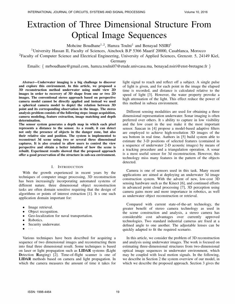
Our eyes are separated by a distance of about 6 to 7cm.It makes a difference in the point of view of each eye, andtherefore the aspect of every scene is slightly different in theeyes. When these two different pictures fuse in the brain, itmakes a 3D scene (Figure 1). The same principled have beenapplied in our method. The stereo camera capture a sceneinto different views. from these views we form the threedimensional structure included on it.
Figure 1. The Eyes 3D view.
Objectif: Given a set of flow fields or displacement vectorsfrom a moving stereo camera over time, determine:• The sequence of camera poses.• Given optical flow or point correspondences, compute
3D motion (translation-rotation) and shape (depth).• Recovery of 3D shape from 2D images.
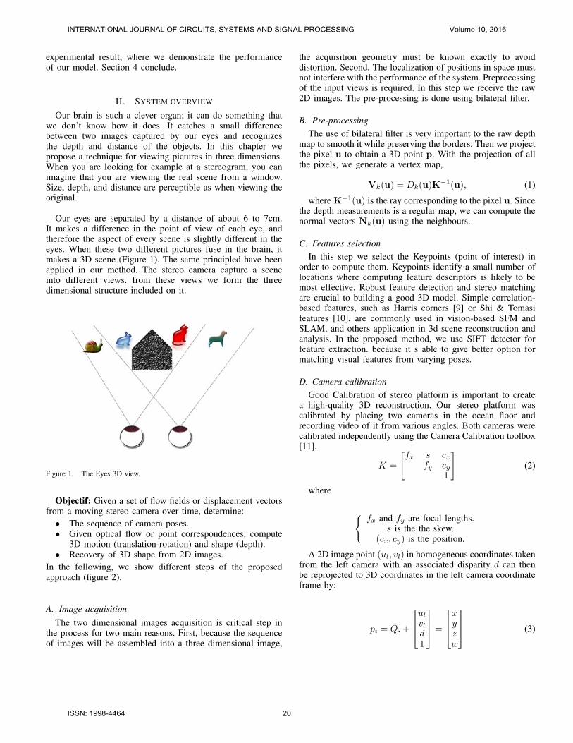
In the following, we show different steps of the proposedapproach (figure 2).
A. Image acquisitionThe two dimensional images acquisition is critical step in
the process for two main reasons. First, because the sequenceof images will be assembled into a three dimensional image,
the acquisition geometry must be known exactly to avoiddistortion. Second, The localization of positions in space mustnot interfere with the performance of the system. Preprocessingof the input views is required. In this step we receive the raw2D images. The pre-processing is done using bilateral filter.
B. Pre-processingThe use of bilateral filter is very important to the raw depth
map to smooth it while preserving the borders. Then we projectthe pixel u to obtain a 3D point p. With the projection of allthe pixels, we generate a vertex map,
Vk(u) = Dk(u)K−1(u), (1)
where K−1(u) is the ray corresponding to the pixel u. Sincethe depth measurements is a regular map, we can compute thenormal vectors Nk(u) using the neighbours.
C. Features selectionIn this step we select the Keypoints (point of interest) in
order to compute them. Keypoints identify a small number oflocations where computing feature descriptors is likely to bemost effective. Robust feature detection and stereo matchingare crucial to building a good 3D model. Simple correlation-based features, such as Harris corners [9] or Shi & Tomasifeatures [10], are commonly used in vision-based SFM andSLAM, and others application in 3d scene reconstruction andanalysis. In the proposed method, we use SIFT detector forfeature extraction. because it s able to give better option formatching visual features from varying poses.
D. Camera calibrationGood Calibration of stereo platform is important to create
a high-quality 3D reconstruction. Our stereo platform wascalibrated by placing two cameras in the ocean floor andrecording video of it from various angles. Both cameras werecalibrated independently using the Camera Calibration toolbox[11].
K =
[fx s cx
fy cy1
](2)
where
{fx and fy are focal lengths.
s is the the skew.(cx, cy) is the position.
A 2D image point (ul, vl) in homogeneous coordinates takenfrom the left camera with an associated disparity d can thenbe reprojected to 3D coordinates in the left camera coordinateframe by:
pi = Q.+
ul
vld1
=
xyzw
(3)
INTERNATIONAL JOURNAL OF CIRCUITS, SYSTEMS AND SIGNAL PROCESSING Volume 10, 2016
ISSN: 1998-4464 20
3
where Q is the reprojection matrix resulting from therectification, and Tx is the baseline of the stereo platform
1 0 0 −cx0 1 0 −cy0 0 0 f
0 0 −1Tx
cx−c′xTx
(4)
The 3D coordinates with respect to the left cameras coordinateframe are then given by
(x
w,y
w,z
w)
E. Disparity matrix
Depth map is an image or image channel that containsinformation relating to the distance of the surfaces of sceneobjects from a viewpoint (shown equation 4).
F. Motion analysis (using optical flow)
The approach to motion analysis presented in [8] triesto determine the instantaneous displacement of every pixelbetween successive images. If one assumes that the intensitychange is due only to camera and objects movements, theinstantaneous speed of the pixel satisfies the following optical-flow:
∂I(x, y, t).u
∂x+
∂I(x, y, t).v
∂y+
∂I(x, y, t)
∂t= 0, (5)
where I(x, y, t) is the image intensity, and the partialderivatives are generally estimated from the image by usingspatial and temporal differences. If we want (1) to be a goodapproximation, the 2-D speed should be low, usually one ortwo pixels per frame.
G. Point cloud
A point cloud is just what it sounds like: a cloud of points in3d space that contains one or more channels of data (lighting,occlusion, area, etc) at each point. Point clouds are importantbecause they are the immediate precursor to a brick map,which is a useful structure for caching data as a 3d texture. Apoint cloud is a data structure used to represent a collection ofmulti-dimensional points. These points usually represent theX, Y, and Z geometric coordinates of an underlying sampledsurface.
H. 3D reconstruction
Here we obtain the final structure of the 3D object.
Figure 2. 3D reconstruction process.
III. EXPERIMENTAL RESULTS
We have developed a system for real-time monitoring basedon smart algorithms presented. The system is implemented ona standard PC. we use a different images on different size andcomplexity.
Framework used:• OpenCV: (Open Source Computer Vision) is a library
of programming functions mainly aimed at real-timecomputer vision.
• PCL library (Point cloud library): PCLis a large scale, open project for 2D/3D image and pointcloud processing (in C++, w/ new python bindings).
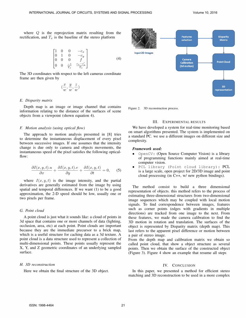
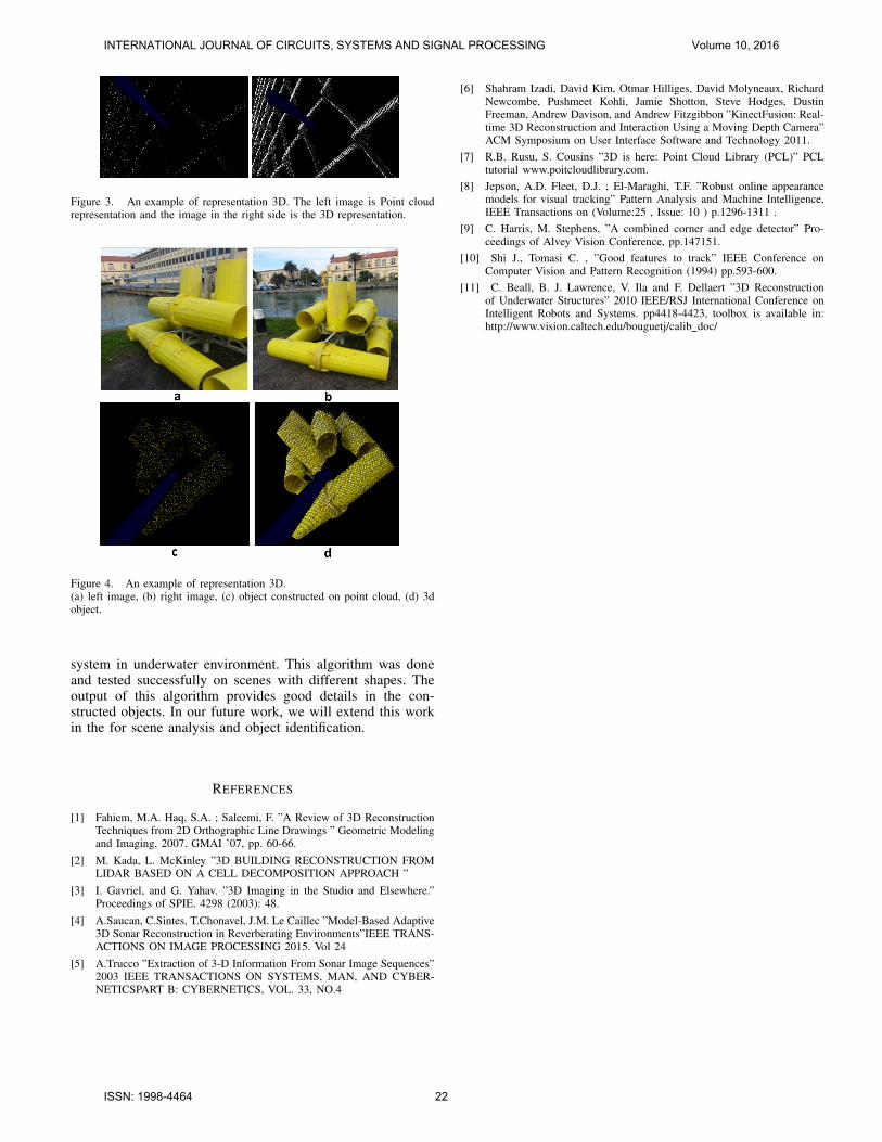
The method consist to build a three dimensionalrepresentation of objects. this method refers to the process ofestimating three-dimensional structures from two-dimensionalimage sequences which may be coupled with local motionsignals. To find correspondence between images, featuressuch as corner points (edges with gradients in multipledirections) are tracked from one image to the next. Fromthese features, we made the camera calibration to find the3D motion in rotation and translation. The surfaces of theobject is represented by Disparity matrix (depth map). Thislast refers to the apparent pixel difference or motion betweena pair of stereo image.From the depth map and calibration matrix we obtain socalled point cloud, that show a object structure as severalpoints. Then we obtain the surface of the constructed object(Figure 3). Figure 4 show an example that resume all steps
IV. CONCLUSION
In this paper, we presented a method for efficient stereomatching and 3D reconstruction to be used in a more complex
INTERNATIONAL JOURNAL OF CIRCUITS, SYSTEMS AND SIGNAL PROCESSING Volume 10, 2016
ISSN: 1998-4464 21
4
Figure 3. An example of representation 3D. The left image is Point cloudrepresentation and the image in the right side is the 3D representation.
Figure 4. An example of representation 3D.(a) left image, (b) right image, (c) object constructed on point cloud, (d) 3dobject.
system in underwater environment. This algorithm was doneand tested successfully on scenes with different shapes. Theoutput of this algorithm provides good details in the con-structed objects. In our future work, we will extend this workin the for scene analysis and object identification.
REFERENCES
[1] Fahiem, M.A. Haq, S.A. ; Saleemi, F. ”A Review of 3D ReconstructionTechniques from 2D Orthographic Line Drawings ” Geometric Modelingand Imaging, 2007. GMAI ’07, pp. 60-66.
[2] M. Kada, L. McKinley ”3D BUILDING RECONSTRUCTION FROMLIDAR BASED ON A CELL DECOMPOSITION APPROACH ”
[3] I. Gavriel, and G. Yahav. ”3D Imaging in the Studio and Elsewhere.”Proceedings of SPIE. 4298 (2003): 48.
[4] A.Saucan, C.Sintes, T.Chonavel, J.M. Le Caillec ”Model-Based Adaptive3D Sonar Reconstruction in Reverberating Environments”IEEE TRANS-ACTIONS ON IMAGE PROCESSING 2015. Vol 24
[5] A.Trucco ”Extraction of 3-D Information From Sonar Image Sequences”2003 IEEE TRANSACTIONS ON SYSTEMS, MAN, AND CYBER-NETICSPART B: CYBERNETICS, VOL. 33, NO.4
[6] Shahram Izadi, David Kim, Otmar Hilliges, David Molyneaux, RichardNewcombe, Pushmeet Kohli, Jamie Shotton, Steve Hodges, DustinFreeman, Andrew Davison, and Andrew Fitzgibbon ”KinectFusion: Real-time 3D Reconstruction and Interaction Using a Moving Depth Camera”ACM Symposium on User Interface Software and Technology 2011.
[7] R.B. Rusu, S. Cousins ”3D is here: Point Cloud Library (PCL)” PCLtutorial www.poitcloudlibrary.com.
[8] Jepson, A.D. Fleet, D.J. ; El-Maraghi, T.F. ”Robust online appearancemodels for visual tracking” Pattern Analysis and Machine Intelligence,IEEE Transactions on (Volume:25 , Issue: 10 ) p.1296-1311 .
[9] C. Harris, M. Stephens, ”A combined corner and edge detector” Pro-ceedings of Alvey Vision Conference, pp.147151.
[10] Shi J., Tomasi C. , ”Good features to track” IEEE Conference onComputer Vision and Pattern Recognition (1994) pp.593-600.
[11] C. Beall, B. J. Lawrence, V. Ila and F. Dellaert ”3D Reconstructionof Underwater Structures” 2010 IEEE/RSJ International Conference onIntelligent Robots and Systems. pp4418-4423, toolbox is available in:http://www.vision.caltech.edu/bouguetj/calib doc/
INTERNATIONAL JOURNAL OF CIRCUITS, SYSTEMS AND SIGNAL PROCESSING Volume 10, 2016
ISSN: 1998-4464 22