INTERNATIONAL ISO STANDARD...
46
Reference number ISO 21138-3:2007(E) INTERNATIONAL STANDARD ISO 21138-3 First edition 2007-10-15 Plastics piping systems for non-pressure underground drainage and sewerage — Structured-wall piping systems of unplasticized poly(vinyl chloride) (PVC-U), polypropylene (PP) and polyethylene (PE) — Part 3: Pipes and fittings with non-smooth external surface, Type B Systèmes de canalisations en plastique pour les branchements et les collecteurs d'assainissement sans pression enterrés — Systèmes de canalisations à parois structurées en poly(chlorure de vinyle) non plastifié (PVC-U), polypropylène (PP) et polyéthylène (PE) — Partie 3: Tubes et raccords avec une surface externe non lisse, type B No reproduction or networking permitted without license from IHS --`,```,``,`,,`,`,`,,``,``,`,`,-`-`,,`,,`,`,,`---
Transcript of INTERNATIONAL ISO STANDARD...
Reference numberISO 21138-3:2007(E)
© ISO 2007
INTERNATIONAL STANDARD
ISO21138-3
First edition2007-10-15
Plastics piping systems for non-pressure underground drainage and sewerage — Structured-wall piping systems of unplasticized poly(vinyl chloride) (PVC-U), polypropylene (PP) and polyethylene (PE) — Part 3: Pipes and fittings with non-smooth external surface, Type B
Systèmes de canalisations en plastique pour les branchements et les collecteurs d'assainissement sans pression enterrés — Systèmes de canalisations à parois structurées en poly(chlorure de vinyle) non plastifié (PVC-U), polypropylène (PP) et polyéthylène (PE) —
Partie 3: Tubes et raccords avec une surface externe non lisse, type B
Copyright International Organization for Standardization Provided by IHS under license with ISO Licensee=IHS Employees/1111111001, User=leee, leee
Not for Resale, 11/22/2007 19:22:36 MSTNo reproduction or networking permitted without license from IHS
--`,```,``,`,,`,`,`,,``,``,`,`,-`-`,,`,,`,`,,`---
ISO 21138-3:2007(E)
PDF disclaimer This PDF file may contain embedded typefaces. In accordance with Adobe's licensing policy, this file may be printed or viewed but shall not be edited unless the typefaces which are embedded are licensed to and installed on the computer performing the editing. In downloading this file, parties accept therein the responsibility of not infringing Adobe's licensing policy. The ISO Central Secretariat accepts no liability in this area.
Adobe is a trademark of Adobe Systems Incorporated.
Details of the software products used to create this PDF file can be found in the General Info relative to the file; the PDF-creation parameters were optimized for printing. Every care has been taken to ensure that the file is suitable for use by ISO member bodies. In the unlikely event that a problem relating to it is found, please inform the Central Secretariat at the address given below.
COPYRIGHT PROTECTED DOCUMENT © ISO 2007 All rights reserved. Unless otherwise specified, no part of this publication may be reproduced or utilized in any form or by any means, electronic or mechanical, including photocopying and microfilm, without permission in writing from either ISO at the address below or ISO's member body in the country of the requester.
ISO copyright office Case postale 56 • CH-1211 Geneva 20 Tel. + 41 22 749 01 11 Fax + 41 22 749 09 47 E-mail [email protected] Web www.iso.org
Published in Switzerland
ii © ISO 2007 – All rights reserved
Copyright International Organization for Standardization Provided by IHS under license with ISO Licensee=IHS Employees/1111111001, User=leee, leee
Not for Resale, 11/22/2007 19:22:36 MSTNo reproduction or networking permitted without license from IHS
--`,```,``,`,,`,`,`,,``,``,`,`,-`-`,,`,,`,`,,`---
ISO 21138-3:2007(E)
© ISO 2007 – All rights reserved iii
Contents Page
Foreword............................................................................................................................................................ iv Introduction ........................................................................................................................................................ v 1 Scope ..................................................................................................................................................... 1 2 Normative references ........................................................................................................................... 2 3 Terms, definitions, symbols and abbreviated terms......................................................................... 4 3.1 Terms and definitions........................................................................................................................... 4 3.2 Symbols ................................................................................................................................................. 4 3.3 Abbreviated terms ................................................................................................................................ 5 4 Material .................................................................................................................................................. 5 4.1 General................................................................................................................................................... 5 4.2 Unplasticized poly(vinyl chloride) (PVC-U) ........................................................................................ 6 4.3 Polypropylene (PP) ............................................................................................................................... 7 4.4 Polyethylene (PE).................................................................................................................................. 9 4.5 Sealing ring retaining components................................................................................................... 11 4.6 Sealing rings ....................................................................................................................................... 11 4.7 Fused or welded joints ....................................................................................................................... 11 4.8 Adhesives for PVC-U.......................................................................................................................... 11 5 Designation of wall construction and examples of typical jointing methods .............................. 12 5.1 Wall constructions designated as Type B........................................................................................ 12 5.2 Designation and design of joints ...................................................................................................... 13 6 General characteristics for pipes and fittings — Colour ................................................................ 13 7 Geometrical characteristics............................................................................................................... 13 7.1 General................................................................................................................................................. 13 7.2 Dimensions.......................................................................................................................................... 13 7.3 Types of fitting .................................................................................................................................... 17 8 Physical characteristics..................................................................................................................... 18 8.1 Unplasticized poly(vinyl chloride) (PVC-U) ...................................................................................... 18 8.2 Polypropylene (PP) ............................................................................................................................. 19 8.3 Polyethylene (PE)................................................................................................................................ 19 9 Mechanical characteristics ................................................................................................................ 20 9.1 Mechanical characteristics of pipes ................................................................................................. 20 9.2 Mechanical characteristics of fittings............................................................................................... 22 10 Performance requirements ................................................................................................................ 24 11 Marking ................................................................................................................................................ 25 11.1 General................................................................................................................................................. 25 11.2 Minimum required marking................................................................................................................ 25 Annex A (normative) Virgin PVC-U material.................................................................................................. 27 Annex B (normative) Utilization of non-virgin PVC-U material.................................................................... 28 Annex C (normative) Virgin PP material ........................................................................................................ 31 Annex D (normative) Utilization of non-virgin PP material .......................................................................... 32 Annex E (normative) Virgin PE material ........................................................................................................ 34 Annex F (normative) Utilization of non-virgin PE material .......................................................................... 35 Annex G (informative) Survey of possible use of reprocessable and recyclable material....................... 38 Bibliography ..................................................................................................................................................... 39
Copyright International Organization for Standardization Provided by IHS under license with ISO Licensee=IHS Employees/1111111001, User=leee, leee
Not for Resale, 11/22/2007 19:22:36 MSTNo reproduction or networking permitted without license from IHS
--`,```,``,`,,`,`,`,,``,``,`,`,-`-`,,`,,`,`,,`---
ISO 21138-3:2007(E)
iv © ISO 2007 – All rights reserved
Foreword
ISO (the International Organization for Standardization) is a worldwide federation of national standards bodies (ISO member bodies). The work of preparing International Standards is normally carried out through ISO technical committees. Each member body interested in a subject for which a technical committee has been established has the right to be represented on that committee. International organizations, governmental and non-governmental, in liaison with ISO, also take part in the work. ISO collaborates closely with the International Electrotechnical Commission (IEC) on all matters of electrotechnical standardization.
International Standards are drafted in accordance with the rules given in the ISO/IEC Directives, Part 2.
The main task of technical committees is to prepare International Standards. Draft International Standards adopted by the technical committees are circulated to the member bodies for voting. Publication as an International Standard requires approval by at least 75 % of the member bodies casting a vote.
Attention is drawn to the possibility that some of the elements of this document may be the subject of patent rights. ISO shall not be held responsible for identifying any or all such patent rights.
ISO 21138-3 was prepared by Technical Committee ISO/TC 138, Plastics pipes, fittings and valves for the transport of fluids, Subcommittee SC 1, Plastics pipes and fittings for soil, waste and drainage (including land drainage).
ISO 21138 consists of the following parts, under the general title Plastics piping systems for non-pressure underground drainage and sewerage — Structured-wall piping systems of unplasticized poly(vinyl chloride) (PVC-U), polypropylene (PP) and polyethylene (PE):
⎯ Part 1: Material specifications and performance criteria for pipes, fittings and system
⎯ Part 2: Pipes and fittings with smooth external surface, Type A
⎯ Part 3: Pipes and fittings with non-smooth external surface, Type B
Copyright International Organization for Standardization Provided by IHS under license with ISO Licensee=IHS Employees/1111111001, User=leee, leee
Not for Resale, 11/22/2007 19:22:36 MSTNo reproduction or networking permitted without license from IHS
--`,```,``,`,,`,`,`,,``,``,`,`,-`-`,,`,,`,`,,`---
ISO 21138-3:2007(E)
© ISO 2007 – All rights reserved v
Introduction
ISO 21138 is the system standard covering the plastics piping systems for non-pressure underground drainage and sewerage, in particular thermoplastics structured-wall piping systems.
Copyright International Organization for Standardization Provided by IHS under license with ISO Licensee=IHS Employees/1111111001, User=leee, leee
Not for Resale, 11/22/2007 19:22:36 MSTNo reproduction or networking permitted without license from IHS
--`,```,``,`,,`,`,`,,``,``,`,`,-`-`,,`,,`,`,,`---
INTERNATIONAL STANDARD ISO 21138-3:2007(E)
© ISO 2007 – All rights reserved 1
Plastics piping systems for non-pressure underground drainage and sewerage — Structured-wall piping systems of unplasticized poly(vinyl chloride) (PVC-U), polypropylene (PP) and polyethylene (PE) —
Part 3: Pipes and fittings with non-smooth external surface, Type B
1 Scope
This part of ISO 21138, together with ISO 21138-1, specifies the definitions and requirements for pipes with a non-smooth external surface (Type B), fittings and systems based on unplasticized poly(vinyl chloride) (PVC-U), polypropylene (PP) and polyethylene (PE) structured-wall piping systems in the field of non-pressure systems for underground drainage and sewerage.
NOTE 1 These pipes, fittings and the system can be used for highway drainage and surface water.
This part of ISO 21138 specifically refers to PVC, PP and PE materials.
NOTE 2 Other thermoplastic materials may be added via an addendum.
This part of ISO 21138 specifies test methods and test parameters.
This part of ISO 21138 covers a range of pipe and fitting sizes, materials, pipe constructions and nominal ring stiffnesses, and gives recommendations concerning colours.
NOTE 3 It is the responsibility of the purchaser or specifier to make the appropriate selections from these aspects, taking into account their particular requirements and any relevant national regulations and installation practices or codes.
In conjunction with ISO 21138-1, this part of ISO 21138 is applicable to PVC-U, PP and PE structured-wall pipes and fittings, to their joints and to joints with components of other plastics and non-plastics materials intended to be used for buried piping systems for the transport of drainage and sewage.
It is applicable to PVC-U, PP and PE structured-wall pipes and fittings with or without an integral socket with elastomeric ring seal joints as well as welded and fused joints.
NOTE 4 Pipes, fittings and other components conforming to any plastics product standards referred to in Clause 2 can be used with pipes and fittings conforming to this part of ISO 21138, when they conform to the requirements for joint dimensions given in parts 2 and 3 of this International Standard and to the performance requirements given in Clause 10.
NOTE 5 For dimensions larger than DN/OD 1200 or DN/ID 1200 this standard can serve as a general guide regarding appearance, colour, physical and mechanical characteristics as well as performance requirements.
Test methods are not included in this document.
Copyright International Organization for Standardization Provided by IHS under license with ISO Licensee=IHS Employees/1111111001, User=leee, leee
Not for Resale, 11/22/2007 19:22:36 MSTNo reproduction or networking permitted without license from IHS
--`,```,``,`,,`,`,`,,``,``,`,`,-`-`,,`,,`,`,,`---
ISO 21138-3:2007(E)
2 © ISO 2007 – All rights reserved
2 Normative references
The following referenced documents are indispensable for the application of this document. For dated references, only the edition cited applies. For undated references, the latest edition of the referenced document (including any amendments) applies.
ISO 178, Plastics — Determination of flexural properties
ISO 306:1994, Plastics — Thermoplastic materials — Determination of Vicat softening temperature (VST)
ISO 527-2:1993, Plastics — Determination of tensile properties — Part 2: Test conditions for moulding and extrusion plastics
ISO 580:2005, Plastics piping and ducting systems — Injection-moulded thermoplastics fittings — Methods for visually assessing the effects of heating
ISO 1133:2005, Plastics — Determination of the melt mass-flow rate (MFR) and the melt volume-flow rate (MVR) of thermoplastics
ISO 1167-1, Thermoplastics pipes, fittings and assemblies for the conveyance of fluids — Determination of the resistance to internal pressure — Part 1: General method
ISO 1167-2, Thermoplastics pipes, fittings and assemblies for the conveyance of fluids — Determination of the resistance to internal pressure — Part 2: Preparation of pipe test pieces
ISO 1183-1, Plastics — Methods for determining the density of non-cellular plastics — Part 1: Immersion method, liquid pyknometer method and titration method
ISO 2507-1, Thermoplastics pipes and fittings — Vicat softening temperature — Part 1: General test method
ISO 2507-2, Thermoplastics pipes and fittings — Vicat softening temperature — Part 2: Test conditions for unplasticized poly(vinyl chloride) (PVC-U) or chlorinated poly(vinyl chloride) (PVC-C) pipes and fittings and for high impact resistance poly(vinyl chloride) (PVC-Hi) pipes
ISO 3126, Plastics piping systems — Plastics components — Determination of dimensions
ISO 3127, Thermoplastics pipes — Determination of resistance to external blows — Round-the-clock method
ISO 3451-1:1997, Plastics — Determination of ash — Part 1: General methods
ISO 4435:2003, Plastics piping systems for non-pressure underground drainage and sewerage — Unplasticized poly(vinyl chloride) (PVC-U)
ISO 8772:2006, Plastics piping systems for non-pressure underground drainage and sewerage — Polyethylene (PE)
ISO 8773:2006, Plastics piping systems for non-pressure underground drainage and sewerage — Polypropylene (PP)
ISO 9852, Unplasticized poly(vinyl chloride) (PVC-U) pipes — Dichloromethane resistance at specified temperature (DCMT) — Test method
ISO 9967, Thermoplastics pipes — Determination of creep ratio
ISO 9969, Thermoplastics pipes — Determination of ring stiffness
ISO 11173, Thermoplastics pipes — Determination of resistance to external blows — Staircase method
Copyright International Organization for Standardization Provided by IHS under license with ISO Licensee=IHS Employees/1111111001, User=leee, leee
Not for Resale, 11/22/2007 19:22:36 MSTNo reproduction or networking permitted without license from IHS
--`,```,``,`,,`,`,`,,``,``,`,`,-`-`,,`,,`,`,,`---
ISO 21138-3:2007(E)
© ISO 2007 – All rights reserved 3
ISO 11357-6, Plastics — Differential scanning calorimetry (DSC) — Part 6: Determination of oxidation induction time (isothermal OIT) and oxidation induction temperature (dynamic OIT)
ISO 12091, Structured-wall thermoplastics pipes — Oven test
ISO 13967, Thermoplastics fittings — Determination of ring stiffness
ISO 21138-1, Plastics piping systems for non-pressure underground drainage and sewerage — Structured-wall piping systems of unplasticized poly(vinyl chloride) (PVC-U), polypropylene (PP) and polyethylene (PE) — Part 1: Material specifications and performance criteria for pipes, fittings and system
ISO 21138-2, Plastics piping systems for non-pressure underground drainage and sewerage — Structured-wall piping systems of unplasticized poly(vinyl chloride) (PVC-U), polypropylene (PP) and polyethylene (PE) — Part 2: Pipes and fittings with smooth external surface, Type A
ISO 22088-3, Plastics — Determination of resistance to environmental stress cracking (ESC) — Part 3: Bent strip method
EN 681-1, Elastomeric seals — Materials requirements for pipe joint seals used in water and drainage applications — Part 1: Vulcanized rubber
EN 681-2, Elastomeric seals — Materials requirements for pipe joint seals used in water and drainage applications — Part 2: Thermoplastic elastomers
EN 681-4, Elastomeric seals — Materials requirements for pipe joint seals used in water and drainage applications — Part 4: Cast polyurethane sealing elements
EN 922, Plastics piping and ducting systems — Pipes and fittings of unplasticized poly(vinyl chloride) (PVC-U) — Specimen preparation for determination of the viscosity number and calculation of the K-value
EN 1053, Plastics piping systems — Thermoplastics piping systems for non-pressure applications — Test method for watertightness
EN 1277:2003, Plastics piping systems — Thermoplastics piping systems for buried non-pressure applications — Test methods for leaktightness of elastomeric sealing ring type joints
EN 1437:2002, Plastics piping systems — Piping systems for underground drainage and sewerage — Test method for resistance to combined temperature cycling and external loading
EN 1446, Plastics piping and ducting systems — Thermoplastics pipes — Determination of ring flexibility
EN 1905, Plastics piping systems — Unplasticized poly(vinyl chloride) (PVC-U) pipes, fittings and material — Method for assessment of the PVC content based on total chlorine content
EN 1979, Plastics piping and ducting systems — Thermoplastics spirally-formed structured-wall pipes — Determination of the tensile strength of a seam
EN 10204:2004, Metallic products — Types of inspection documents
EN 12061, Plastics piping systems ⎯ Thermoplastics fittings ⎯ Test method for impact resistance
EN 12099, Plastics piping systems — Polyethylene piping materials and components — Determination of volatile content
EN 12256, Plastics piping systems — Thermoplastics fittings — Test method for mechanical strength or flexibility of fabricated fittings
Copyright International Organization for Standardization Provided by IHS under license with ISO Licensee=IHS Employees/1111111001, User=leee, leee
Not for Resale, 11/22/2007 19:22:36 MSTNo reproduction or networking permitted without license from IHS
--`,```,``,`,,`,`,`,,``,``,`,`,-`-`,,`,,`,`,,`---
ISO 21138-3:2007(E)
4 © ISO 2007 – All rights reserved
EN 14741, Thermoplastics piping and ducting systems — Joints for buried non-pressure applications — Test method for the long-term sealing performance of joints with elastomeric seals by estimating the sealing pressure
EN 15344:—1), Plastics — Recycled plastics — Characterisation of polyethylene)(PE) recyclates
EN 15345:—1), Plastics — Recycled plastics — Characterisation of polypropylene)(PP) recyclates
EN 15346:—1), Plastics — Recycled plastics — Characterisation of poly(vinyl chloride)(PVC) recyclates
3 Terms, definitions, symbols and abbreviated terms
For the purposes of this document, the following terms, definitions, symbols and abbreviated terms apply.
3.1 Terms and definitions
The terms and definitions given in ISO 21138-1 apply.
3.2 Symbols
A length of engagement, or maximum pull-out whilst maintaining tightness
Di socket inside diameter
Dim,min minimum mean inside diameter of a socket
de outside diameter
dem mean outside diameter
di inside diameter
dim mean inside diameter
e wall thickness (at any point)
ec construction height
e2 wall thickness of the socket
e3 wall thickness of the groove
e4 wall thickness of the inside layer (waterway wall thickness)
e5 wall thickness of the inside layer under a hollow section
F distance from the spigot end to the effective sealing point
l effective length of a pipe
L1,min minimum length of a spigot
1) To be published.
Copyright International Organization for Standardization Provided by IHS under license with ISO Licensee=IHS Employees/1111111001, User=leee, leee
Not for Resale, 11/22/2007 19:22:36 MSTNo reproduction or networking permitted without license from IHS
--`,```,``,`,,`,`,`,,``,``,`,`,-`-`,,`,,`,`,,`---
ISO 21138-3:2007(E)
© ISO 2007 – All rights reserved 5
3.3 Abbreviated terms
CaCO3 calcium carbonate
CT close tolerance class
DN nominal size
DN/ID nominal size related to inside diameter
DN/OD nominal size related to outside diameter
ID inside diameter
MgCO3 magnesium carbonate
MFR melt mass-flow rate
OD outside diameter
OIT oxidation induction time
PE polyethylene
PP polypropylene
PVC-U unplasticized poly(vinyl chloride)
S pipe series S
SDR standard dimension ratio
SN nominal ring stiffness
TIR true impact rate
TPE thermoplastic elastomer
VST Vicat softening temperature
4 Material
4.1 General
The material shall be one of the following, unplasticized poly(vinyl chloride) (PVC-U), polypropylene (PP) or polyethylene (PE) to which are added those additives that are needed to facilitate the manufacture of components conforming to this part of ISO 21138, including the relevant annexes.
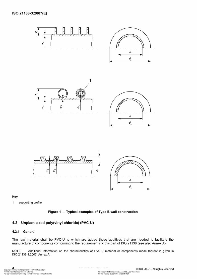
Spirally formed Type B pipes may include a support profile (see Figure 1) made from polymers other than PVC-U, PP or PE.
Spirally formed pipe constructions may include a continuous elastomeric sealing component of a material conforming to EN 681-1, EN 681-2 or EN 681-4 as applicable, or a continuous adhesive conforming to 4.8.
Copyright International Organization for Standardization Provided by IHS under license with ISO Licensee=IHS Employees/1111111001, User=leee, leee
Not for Resale, 11/22/2007 19:22:36 MSTNo reproduction or networking permitted without license from IHS
--`,```,``,`,,`,`,`,,``,``,`,`,-`-`,,`,,`,`,,`---
ISO 21138-3:2007(E)
6 © ISO 2007 – All rights reserved
Key
1 supporting profile
Figure 1 — Typical examples of Type B wall construction
4.2 Unplasticized poly(vinyl chloride) (PVC-U)
4.2.1 General
The raw material shall be PVC-U to which are added those additives that are needed to facilitate the manufacture of components conforming to the requirements of this part of ISO 21138 (see also Annex A).
NOTE Additional information on the characteristics of PVC-U material or components made thereof is given in ISO 21138-1:2007, Annex A.
Copyright International Organization for Standardization Provided by IHS under license with ISO Licensee=IHS Employees/1111111001, User=leee, leee
Not for Resale, 11/22/2007 19:22:36 MSTNo reproduction or networking permitted without license from IHS
--`,```,``,`,,`,`,`,,``,``,`,`,-`-`,,`,,`,`,,`---
ISO 21138-3:2007(E)
© ISO 2007 – All rights reserved 7
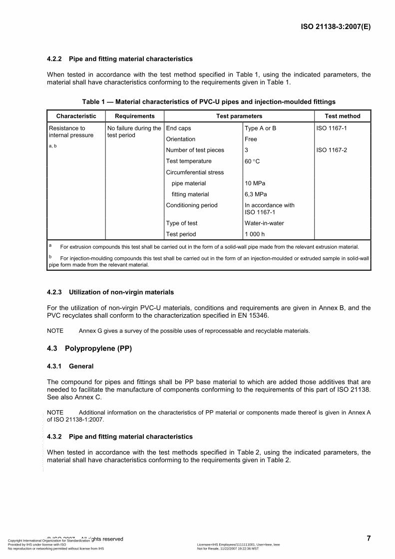
4.2.2 Pipe and fitting material characteristics
When tested in accordance with the test method specified in Table 1, using the indicated parameters, the material shall have characteristics conforming to the requirements given in Table 1.
Table 1 — Material characteristics of PVC-U pipes and injection-moulded fittings
Characteristic Requirements Test parameters Test method
End caps Type A or B
Orientation Free
ISO 1167-1
Number of test pieces 3
Test temperature 60 °C
Circumferential stress
pipe material 10 MPa
fitting material 6,3 MPa
Conditioning period In accordance with ISO 1167-1
Type of test Water-in-water
Resistance to internal pressure
a, b
No failure during the test period
Test period 1 000 h
ISO 1167-2
a For extrusion compounds this test shall be carried out in the form of a solid-wall pipe made from the relevant extrusion material.
b For injection-moulding compounds this test shall be carried out in the form of an injection-moulded or extruded sample in solid-wall pipe form made from the relevant material.
4.2.3 Utilization of non-virgin materials
For the utilization of non-virgin PVC-U materials, conditions and requirements are given in Annex B, and the PVC recyclates shall conform to the characterization specified in EN 15346.
NOTE Annex G gives a survey of the possible uses of reprocessable and recyclable materials.
4.3 Polypropylene (PP)
4.3.1 General
The compound for pipes and fittings shall be PP base material to which are added those additives that are needed to facilitate the manufacture of components conforming to the requirements of this part of ISO 21138. See also Annex C.
NOTE Additional information on the characteristics of PP material or components made thereof is given in Annex A of ISO 21138-1:2007.
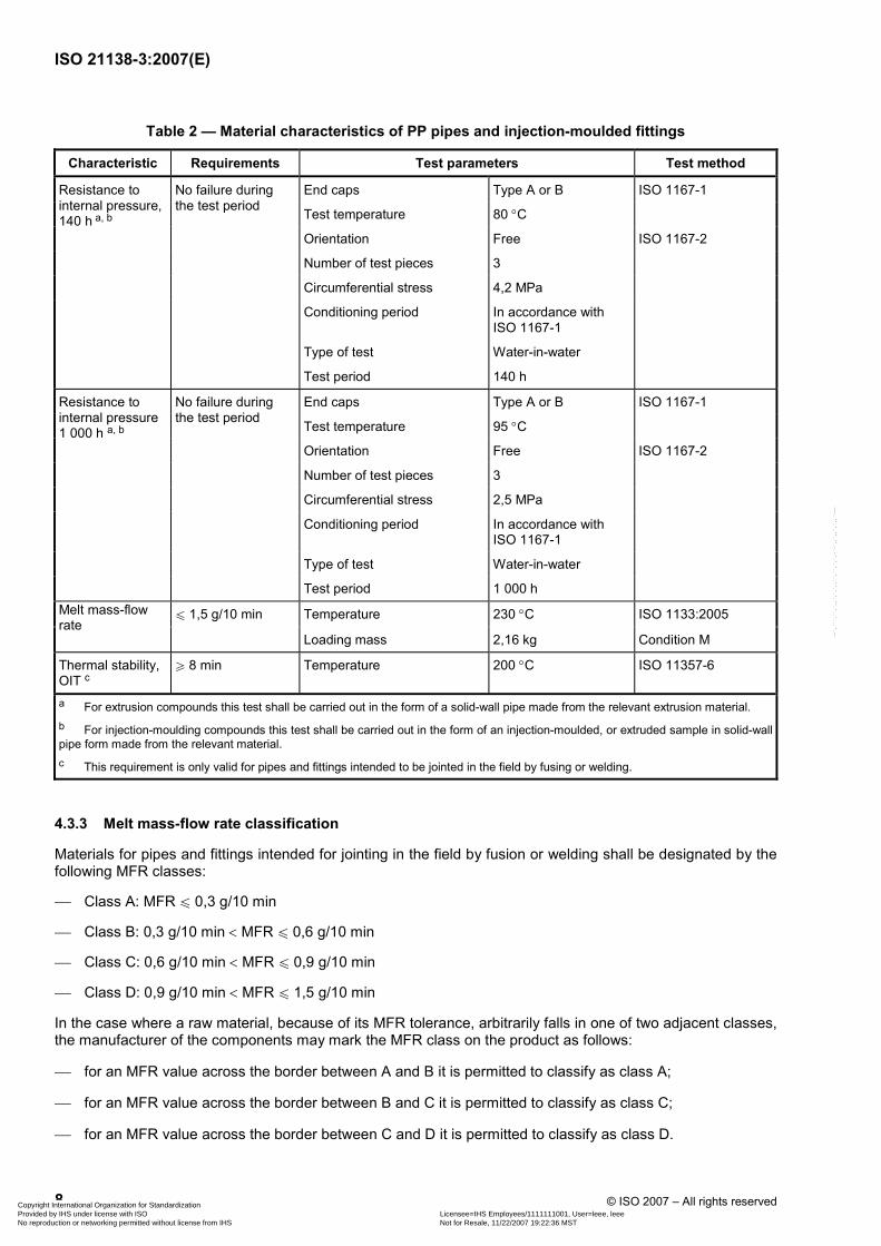
4.3.2 Pipe and fitting material characteristics
When tested in accordance with the test methods specified in Table 2, using the indicated parameters, the material shall have characteristics conforming to the requirements given in Table 2.
Copyright International Organization for Standardization Provided by IHS under license with ISO Licensee=IHS Employees/1111111001, User=leee, leee
Not for Resale, 11/22/2007 19:22:36 MSTNo reproduction or networking permitted without license from IHS
--`,```,``,`,,`,`,`,,``,``,`,`,-`-`,,`,,`,`,,`---
ISO 21138-3:2007(E)
8 © ISO 2007 – All rights reserved
Table 2 — Material characteristics of PP pipes and injection-moulded fittings
Characteristic Requirements Test parameters Test method
End caps Type A or B ISO 1167-1
Test temperature 80 °C
Orientation Free ISO 1167-2
Number of test pieces 3
Circumferential stress 4,2 MPa
Conditioning period In accordance with ISO 1167-1
Type of test Water-in-water
Resistance to internal pressure, 140 h a, b
No failure during the test period
Test period 140 h
End caps Type A or B ISO 1167-1
Test temperature 95 °C
Orientation Free ISO 1167-2
Number of test pieces 3
Circumferential stress 2,5 MPa
Conditioning period In accordance with ISO 1167-1
Type of test Water-in-water
Resistance to internal pressure 1 000 h a, b
No failure during the test period
Test period 1 000 h
Temperature 230 °C ISO 1133:2005 Melt mass-flow rate
u 1,5 g/10 min
Loading mass 2,16 kg Condition M
Thermal stability, OIT c
W 8 min Temperature 200 °C ISO 11357-6
a For extrusion compounds this test shall be carried out in the form of a solid-wall pipe made from the relevant extrusion material. b For injection-moulding compounds this test shall be carried out in the form of an injection-moulded, or extruded sample in solid-wall pipe form made from the relevant material. c This requirement is only valid for pipes and fittings intended to be jointed in the field by fusing or welding.
4.3.3 Melt mass-flow rate classification
Materials for pipes and fittings intended for jointing in the field by fusion or welding shall be designated by the following MFR classes:
⎯ Class A: MFR u 0,3 g/10 min
⎯ Class B: 0,3 g/10 min < MFR u 0,6 g/10 min
⎯ Class C: 0,6 g/10 min < MFR u 0,9 g/10 min
⎯ Class D: 0,9 g/10 min < MFR u 1,5 g/10 min
In the case where a raw material, because of its MFR tolerance, arbitrarily falls in one of two adjacent classes, the manufacturer of the components may mark the MFR class on the product as follows:
⎯ for an MFR value across the border between A and B it is permitted to classify as class A;
⎯ for an MFR value across the border between B and C it is permitted to classify as class C;
⎯ for an MFR value across the border between C and D it is permitted to classify as class D.
Copyright International Organization for Standardization Provided by IHS under license with ISO Licensee=IHS Employees/1111111001, User=leee, leee
Not for Resale, 11/22/2007 19:22:36 MSTNo reproduction or networking permitted without license from IHS
--`,```,``,`,,`,`,`,,``,``,`,`,-`-`,,`,,`,`,,`---
ISO 21138-3:2007(E)
© ISO 2007 – All rights reserved 9
4.3.4 Utilization of non-virgin materials
For the utilization of non-virgin PP materials, conditions and requirements are given in Annex D, and the PP recyclates shall conform to the characterization specified in EN 15345.
NOTE Annex G gives a survey of the possible uses of reprocessable and recyclable materials.
4.4 Polyethylene (PE)
4.4.1 General
The base material shall be polyethylene (PE) to which are added those additives that are needed to facilitate the manufacture of components conforming to this part of ISO 21138. See also Annex E.
NOTE Additional information on the characteristics of PE material or components made thereof is given in Annex A of ISO 21138-1:2007.
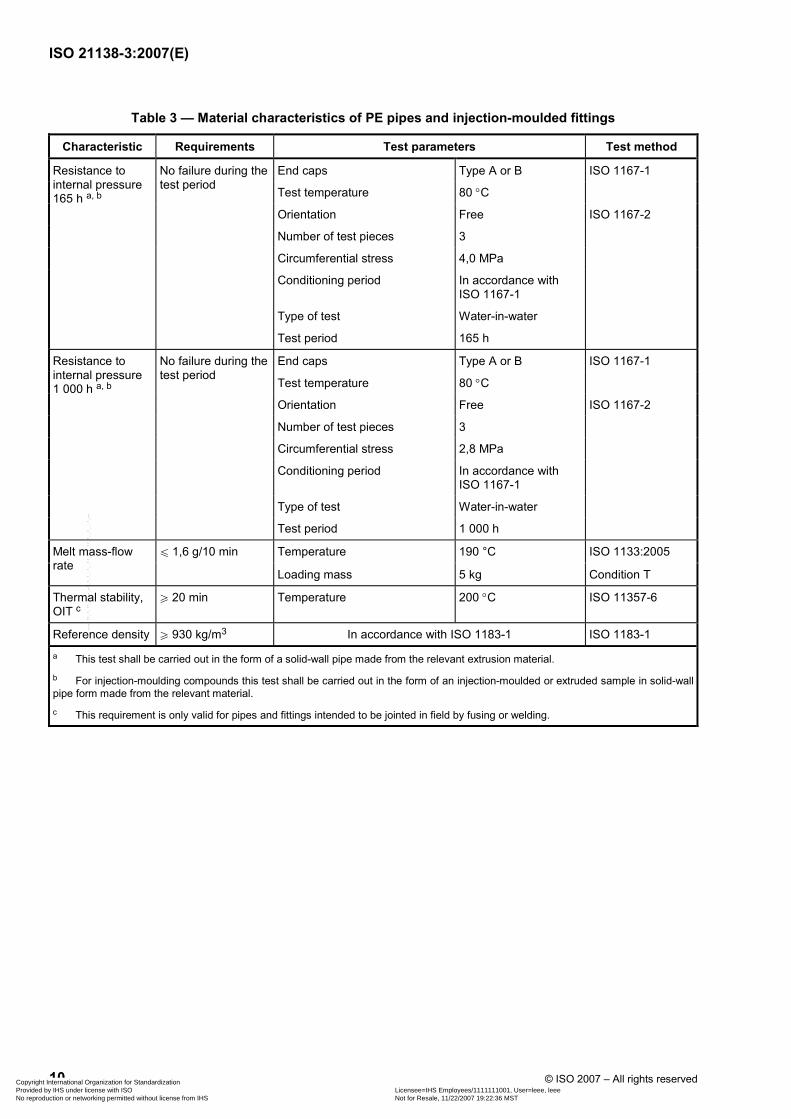
4.4.2 Material characteristics of pipes and injection-moulded fittings
When tested in accordance with the test method specified in Table 3, using the indicated parameters, the material shall have characteristics conforming to the requirements given in Table 3.
4.4.3 Material characteristics of rotational-moulded fittings
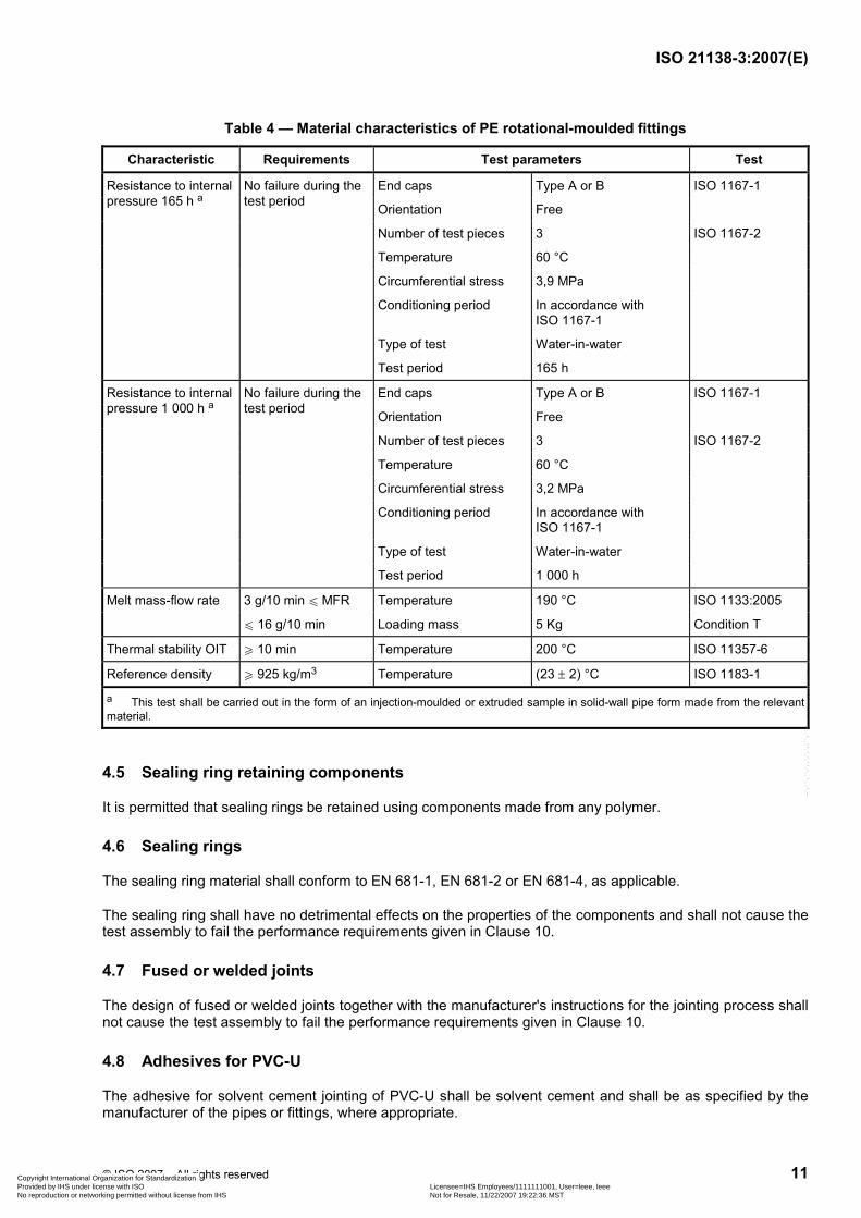
When tested in accordance with the test methods specified in Table 4, using the indicated parameters, the material shall have characteristics conforming to the requirements given in Table 4.
4.4.4 Utilization of non-virgin materials
For the utilization of non-virgin PE materials, conditions and requirements are given in Annex F, and the PE recyclates shall conform to the characterization specified in EN 15344.
NOTE Annex G gives a survey of the possible uses of reprocessable and recyclable materials.
Copyright International Organization for Standardization Provided by IHS under license with ISO Licensee=IHS Employees/1111111001, User=leee, leee
Not for Resale, 11/22/2007 19:22:36 MSTNo reproduction or networking permitted without license from IHS
--`,```,``,`,,`,`,`,,``,``,`,`,-`-`,,`,,`,`,,`---
ISO 21138-3:2007(E)
10 © ISO 2007 – All rights reserved
Table 3 — Material characteristics of PE pipes and injection-moulded fittings
Characteristic Requirements Test parameters Test method
End caps Type A or B ISO 1167-1
Test temperature 80 °C
Orientation Free
Number of test pieces 3
Circumferential stress 4,0 MPa
Conditioning period In accordance with ISO 1167-1
Type of test Water-in-water
Resistance to internal pressure 165 h a, b
No failure during the test period
Test period 165 h
ISO 1167-2
End caps Type A or B ISO 1167-1
Test temperature 80 °C
Orientation Free
Number of test pieces 3
Circumferential stress 2,8 MPa
Conditioning period In accordance with ISO 1167-1
Type of test Water-in-water
Resistance to internal pressure 1 000 h a, b
No failure during the test period
Test period 1 000 h
ISO 1167-2
Temperature 190 °C ISO 1133:2005 Melt mass-flow rate
u 1,6 g/10 min
Loading mass 5 kg Condition T
Thermal stability, OIT c
W 20 min Temperature 200 °C ISO 11357-6
Reference density W 930 kg/m3 In accordance with ISO 1183-1 ISO 1183-1
a This test shall be carried out in the form of a solid-wall pipe made from the relevant extrusion material. b For injection-moulding compounds this test shall be carried out in the form of an injection-moulded or extruded sample in solid-wall pipe form made from the relevant material. c This requirement is only valid for pipes and fittings intended to be jointed in field by fusing or welding.
Copyright International Organization for Standardization Provided by IHS under license with ISO Licensee=IHS Employees/1111111001, User=leee, leee
Not for Resale, 11/22/2007 19:22:36 MSTNo reproduction or networking permitted without license from IHS
--`,```,``,`,,`,`,`,,``,``,`,`,-`-`,,`,,`,`,,`---
ISO 21138-3:2007(E)
© ISO 2007 – All rights reserved 11
Table 4 — Material characteristics of PE rotational-moulded fittings
Characteristic Requirements Test parameters Test
End caps Type A or B
Orientation Free
ISO 1167-1
Number of test pieces 3
Temperature 60 °C
Circumferential stress 3,9 MPa
Conditioning period In accordance with ISO 1167-1
Type of test Water-in-water
Resistance to internal pressure 165 h a
No failure during the test period
Test period 165 h
ISO 1167-2
End caps Type A or B
Orientation Free
ISO 1167-1
Number of test pieces 3
Temperature 60 °C
Circumferential stress 3,2 MPa
Conditioning period In accordance with ISO 1167-1
Type of test Water-in-water
Resistance to internal pressure 1 000 h a
No failure during the test period
Test period 1 000 h
ISO 1167-2
Melt mass-flow rate 3 g/10 min u MFR Temperature 190 °C ISO 1133:2005
u 16 g/10 min Loading mass 5 Kg Condition T
Thermal stability OIT W 10 min Temperature 200 °C ISO 11357-6
Reference density W 925 kg/m3 Temperature (23 ± 2) °C ISO 1183-1
a This test shall be carried out in the form of an injection-moulded or extruded sample in solid-wall pipe form made from the relevant material.
4.5 Sealing ring retaining components
It is permitted that sealing rings be retained using components made from any polymer.
4.6 Sealing rings
The sealing ring material shall conform to EN 681-1, EN 681-2 or EN 681-4, as applicable.
The sealing ring shall have no detrimental effects on the properties of the components and shall not cause the test assembly to fail the performance requirements given in Clause 10.
4.7 Fused or welded joints
The design of fused or welded joints together with the manufacturer's instructions for the jointing process shall not cause the test assembly to fail the performance requirements given in Clause 10.
4.8 Adhesives for PVC-U
The adhesive for solvent cement jointing of PVC-U shall be solvent cement and shall be as specified by the manufacturer of the pipes or fittings, where appropriate.
Copyright International Organization for Standardization Provided by IHS under license with ISO Licensee=IHS Employees/1111111001, User=leee, leee
Not for Resale, 11/22/2007 19:22:36 MSTNo reproduction or networking permitted without license from IHS
--`,```,``,`,,`,`,`,,``,``,`,`,-`-`,,`,,`,`,,`---
ISO 21138-3:2007(E)
12 © ISO 2007 – All rights reserved
The adhesive shall have no detrimental effects on the properties of components and shall not cause the test assembly to fail the performance requirements given in Clause 10.
5 Designation of wall construction and examples of typical jointing methods
NOTE The figures are schematic sketches only to indicate the relevant dimensions. They do not necessarily represent the manufactured components.
5.1 Wall constructions designated as Type B
5.1.1 Ribbed or corrugated construction
A pipe or fitting with a plain inside surface and a solid or hollow spiral or annular ribbed external surface shall be designated Type B.
Typical examples of Type B constructions are shown in Figure 1.
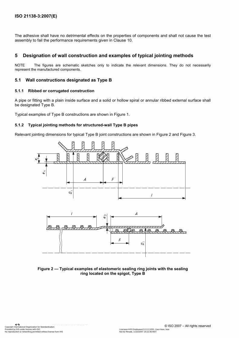
5.1.2 Typical jointing methods for structured-wall Type B pipes
Relevant jointing dimensions for typical Type B joint constructions are shown in Figure 2 and Figure 3.
Figure 2 — Typical examples of elastomeric sealing ring joints with the sealing ring located on the spigot, Type B
Copyright International Organization for Standardization Provided by IHS under license with ISO Licensee=IHS Employees/1111111001, User=leee, leee
Not for Resale, 11/22/2007 19:22:36 MSTNo reproduction or networking permitted without license from IHS
--`,```,``,`,,`,`,`,,``,``,`,`,-`-`,,`,,`,`,,`---
ISO 21138-3:2007(E)
© ISO 2007 – All rights reserved 13
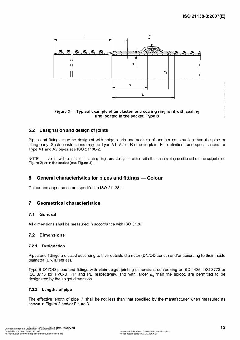
Figure 3 — Typical example of an elastomeric sealing ring joint with sealing ring located in the socket, Type B
5.2 Designation and design of joints
Pipes and fittings may be designed with spigot ends and sockets of another construction than the pipe or fitting body. Such constructions may be Type A1, A2 or B or solid plain. For definitions and specifications for Type A1 and A2 pipes see ISO 21138-2.
NOTE Joints with elastomeric sealing rings are designed either with the sealing ring positioned on the spigot (see Figure 2) or in the socket (see Figure 3).
6 General characteristics for pipes and fittings — Colour
Colour and appearance are specified in ISO 21138-1.
7 Geometrical characteristics
7.1 General
All dimensions shall be measured in accordance with ISO 3126.
7.2 Dimensions
7.2.1 Designation
Pipes and fittings are sized according to their outside diameter (DN/OD series) and/or according to their inside diameter (DN/ID series).
Type B DN/OD pipes and fittings with plain spigot jointing dimensions conforming to ISO 4435, ISO 8772 or ISO 8773 for PVC-U, PP and PE respectively, and with larger de than the spigot, are permitted to be designated by the spigot dimension.
7.2.2 Lengths of pipe
The effective length of pipe, l, shall be not less than that specified by the manufacturer when measured as shown in Figure 2 and/or Figure 3.
Copyright International Organization for Standardization Provided by IHS under license with ISO Licensee=IHS Employees/1111111001, User=leee, leee
Not for Resale, 11/22/2007 19:22:36 MSTNo reproduction or networking permitted without license from IHS
--`,```,``,`,,`,`,`,,``,``,`,`,-`-`,,`,,`,`,,`---
ISO 21138-3:2007(E)
14 © ISO 2007 – All rights reserved
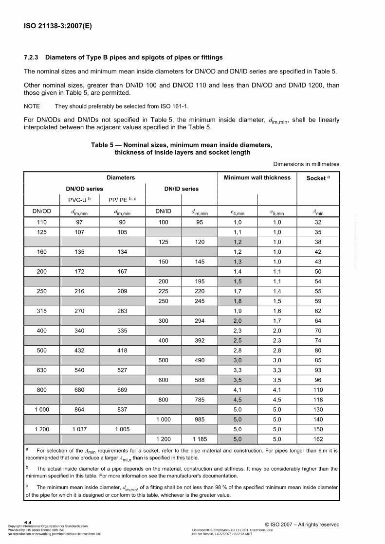
7.2.3 Diameters of Type B pipes and spigots of pipes or fittings
The nominal sizes and minimum mean inside diameters for DN/OD and DN/ID series are specified in Table 5.
Other nominal sizes, greater than DN/ID 100 and DN/OD 110 and less than DN/OD and DN/ID 1200, than those given in Table 5, are permitted.
NOTE They should preferably be selected from ISO 161-1.
For DN/ODs and DN/IDs not specified in Table 5, the minimum inside diameter, dim,min, shall be linearly interpolated between the adjacent values specified in the Table 5.
Table 5 — Nominal sizes, minimum mean inside diameters, thickness of inside layers and socket length
Dimensions in millimetres
Diameters Minimum wall thickness Socket a
DN/OD series DN/ID series
PVC-U b PP/ PE b, c
DN/OD dim,min dim,min DN/ID dim,min e4,min e5,min Amin
110 97 90 100 95 1,0 1,0 32
125 107 105 1,1 1,0 35
125 120 1,2 1,0 38
160 135 134 1,2 1,0 42
150 145 1,3 1,0 43
200 172 167 1,4 1,1 50
200 195 1,5 1,1 54
250 216 209 225 220 1,7 1,4 55
250 245 1,8 1,5 59
315 270 263 1,9 1,6 62
300 294 2,0 1,7 64
400 340 335 2,3 2,0 70
400 392 2,5 2,3 74
500 432 418 2,8 2,8 80
500 490 3,0 3,0 85
630 540 527 3,3 3,3 93
600 588 3,5 3,5 96
800 680 669 4,1 4,1 110
800 785 4,5 4,5 118
1 000 864 837 5,0 5,0 130
1 000 985 5,0 5,0 140
1 200 1 037 1 005 5,0 5,0 150
1 200 1 185 5,0 5,0 162 a For selection of the Amin requirements for a socket, refer to the pipe material and construction. For pipes longer than 6 m it is recommended that one produce a larger Ami,n than is specified in this table.
b The actual inside diameter of a pipe depends on the material, construction and stiffness. It may be considerably higher than the minimum specified in this table. For more information see the manufacturer's documentation.
c The minimum mean inside diameter, dim,min, of a fitting shall be not less than 98 % of the specified minimum mean inside diameter of the pipe for which it is designed or conform to this table, whichever is the greater value.
Copyright International Organization for Standardization Provided by IHS under license with ISO Licensee=IHS Employees/1111111001, User=leee, leee
Not for Resale, 11/22/2007 19:22:36 MSTNo reproduction or networking permitted without license from IHS
--`,```,``,`,,`,`,`,,``,``,`,`,-`-`,,`,,`,`,,`---
ISO 21138-3:2007(E)
© ISO 2007 – All rights reserved 15
DN/OD series pipes and spigots intended to have jointing dimensions as pipes and/or fittings according to ISO 4435, ISO 8772 or ISO 8773 for PVC, PP or PE respectively, shall comply with whichever of those documents is relevant regarding the outside diameters and tolerances of the spigot.
For pipes and fittings not intended to have jointing dimensions as pipes and/or fittings according to ISO 4435, ISO 8772 or ISO 8773 for PVC, PP or PE respectively, the tolerance of the outside diameter of pipe and spigot shall be:
dem, min W 0,994 × de
dem, max u 1,003 × de
where de equals either the nominal size of a DN/OD pipe or the outside diameter as specified by the manufacturer of a DN/ID pipe.
The results are to be rounded to the next higher 0,1 mm.
7.2.4 Diameters and jointing dimensions of sockets and spigots
7.2.4.1 Joints with the elastomeric sealing ring positioned in the socket (combined with Type B pipes or fittings)
For Type B pipes, the requirement regarding the socket and spigot dimension, Amin, specified in Table 5 applies.
In the case where other nominal sizes than those specified in Table 5 are selected for Type B pipes, the requirements regarding the socket dimension Amin shall be linearly interpolated between the adjacent values specified in Table 5.
Di,min shall be equal to de,max.
For Type B pipes greater than DN/OD 630 and DN/ID 600 when they are designed for a specific project, Amin may be shorter than is specified in Table 5. However it shall be not less that 85 mm. Such pipes shall be marked “SHORT SOCKET”.
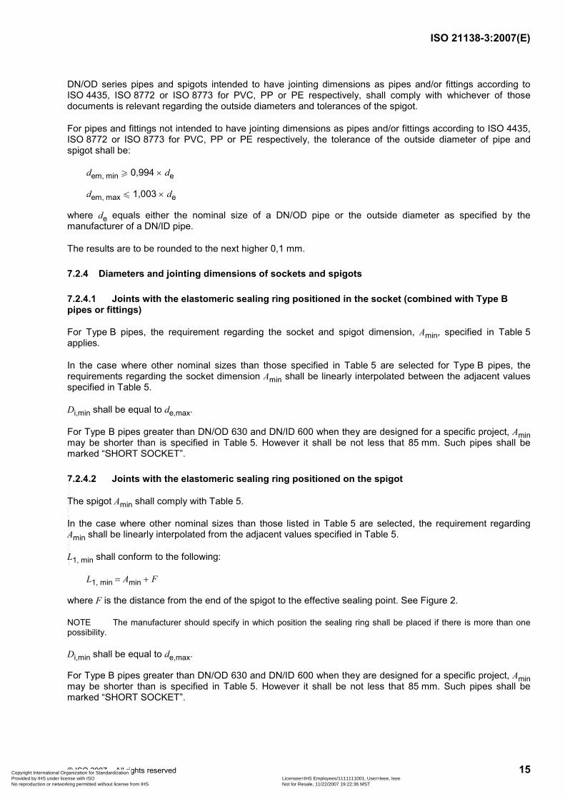
7.2.4.2 Joints with the elastomeric sealing ring positioned on the spigot
The spigot Amin shall comply with Table 5.
In the case where other nominal sizes than those listed in Table 5 are selected, the requirement regarding Amin shall be linearly interpolated from the adjacent values specified in Table 5.
L1, min shall conform to the following:
L1, min = Amin + F
where F is the distance from the end of the spigot to the effective sealing point. See Figure 2.
NOTE The manufacturer should specify in which position the sealing ring shall be placed if there is more than one possibility.
Di,min shall be equal to de,max.
For Type B pipes greater than DN/OD 630 and DN/ID 600 when they are designed for a specific project, Amin may be shorter than is specified in Table 5. However it shall be not less that 85 mm. Such pipes shall be marked “SHORT SOCKET”.
Copyright International Organization for Standardization Provided by IHS under license with ISO Licensee=IHS Employees/1111111001, User=leee, leee
Not for Resale, 11/22/2007 19:22:36 MSTNo reproduction or networking permitted without license from IHS
--`,```,``,`,,`,`,`,,``,``,`,`,-`-`,,`,,`,`,,`---
ISO 21138-3:2007(E)
16 © ISO 2007 – All rights reserved
7.2.5 Wall thicknesses
7.2.5.1 Wall thickness of sockets and joint design requirements
7.2.5.1.1 General
In addition to the minimum required wall thickness of sockets and spigots as specified below, their ring stiffness, when determined in accordance with ISO 9969, shall conform to the following equation:
Sso + Ssp W SNpipe
For the test it is permitted to use cut-off straight socket and spigot parts even if they do not conform to the length requirements specified in ISO 9969.
For dimensions W 500 mm the stiffness may be calculated provided reliable information regarding the E-modulus is available.
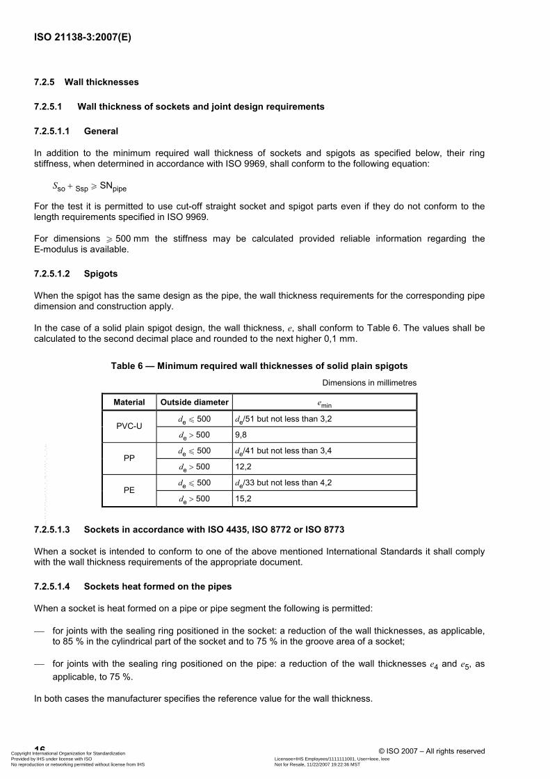
7.2.5.1.2 Spigots
When the spigot has the same design as the pipe, the wall thickness requirements for the corresponding pipe dimension and construction apply.
In the case of a solid plain spigot design, the wall thickness, e, shall conform to Table 6. The values shall be calculated to the second decimal place and rounded to the next higher 0,1 mm.
Table 6 — Minimum required wall thicknesses of solid plain spigots
Dimensions in millimetres
Material Outside diameter emin
de u 500 de/51 but not less than 3,2 PVC-U
de > 500 9,8
de u 500 de/41 but not less than 3,4 PP
de > 500 12,2
de u 500 de/33 but not less than 4,2 PE
de > 500 15,2
7.2.5.1.3 Sockets in accordance with ISO 4435, ISO 8772 or ISO 8773
When a socket is intended to conform to one of the above mentioned International Standards it shall comply with the wall thickness requirements of the appropriate document.
7.2.5.1.4 Sockets heat formed on the pipes
When a socket is heat formed on a pipe or pipe segment the following is permitted:
⎯ for joints with the sealing ring positioned in the socket: a reduction of the wall thicknesses, as applicable, to 85 % in the cylindrical part of the socket and to 75 % in the groove area of a socket;
⎯ for joints with the sealing ring positioned on the pipe: a reduction of the wall thicknesses e4 and e5, as applicable, to 75 %.
In both cases the manufacturer specifies the reference value for the wall thickness.
Copyright International Organization for Standardization Provided by IHS under license with ISO Licensee=IHS Employees/1111111001, User=leee, leee
Not for Resale, 11/22/2007 19:22:36 MSTNo reproduction or networking permitted without license from IHS
--`,```,``,`,,`,`,`,,``,``,`,`,-`-`,,`,,`,`,,`---
ISO 21138-3:2007(E)
© ISO 2007 – All rights reserved 17
7.2.5.1.5 Other sockets with stiffness W 4 kN/m2
For structured-wall designed sockets the wall thicknesses e4 and e5, as applicable, shall comply with the requirements given in Table 5.
7.2.5.1.6 Other sockets with stiffness < 4 kN/m2
The thickness of the inner wall of the socket shall be at least 1,5 × e4 as specified in Table 5.
7.2.5.2 Injection-moulded fittings
The minimum wall thickness in the body of injection-moulded fittings of Type B construction, e4,min, for DN/OD u 315 and DN/ID u 300 shall be 2,0 mm. For larger sizes it shall conform to the requirements for e4, min as specified in Table 5.
The construction height of the body wall, ec, for injection-moulded fittings up to 200 mm DN/OD and up to 200 mm actual outside diameter of pipes in the DN/ID series shall be at least as specified for emin for:
⎯ the SDR 41 series in ISO 4435;
⎯ the SDR 33 series in ISO 8773;
⎯ the SDR 26 series in ISO 8772;
for PVC-U, PP and PE respectively.
In the case of ID series fittings the calculation shall be based on the actual outside diameter of the corresponding pipe.
The jointing design including socket and spigot dimensions shall conform to 7.2.5.1.
7.2.5.3 Fabricated fittings
The wall thickness of the body of fittings fabricated from pipes shall conform to the requirements of the corresponding pipe. Wall thickness reductions due to the process is permitted provided the requirements in Table 16 are satisfied.
The jointing design including socket and spigot dimensions shall conform to 7.2.5.1.
7.2.5.4 Rotational moulded fittings
The minimum wall thickness in the body of rotational-moulded fittings, e4,min, shall be 1,25 × the values specified for injection-moulded fittings, rounded to the next higher 0,1 mm.
If a rotational-moulded fitting has a solid plain spigot and/or socket, the minimum required wall thicknesses e, e2 and e3 as applicable shall be 1,25 × the values derived from 7.2.5.
The socket and spigot dimensions shall comply with 7.2.5.1.
7.3 Types of fitting
The types of fitting covered by this part of ISO 21138 are specified in ISO 21138-1.
Copyright International Organization for Standardization Provided by IHS under license with ISO Licensee=IHS Employees/1111111001, User=leee, leee
Not for Resale, 11/22/2007 19:22:36 MSTNo reproduction or networking permitted without license from IHS
--`,```,``,`,,`,`,`,,``,``,`,`,-`-`,,`,,`,`,,`---
ISO 21138-3:2007(E)
18 © ISO 2007 – All rights reserved
8 Physical characteristics
8.1 Unplasticized poly(vinyl chloride) (PVC-U)
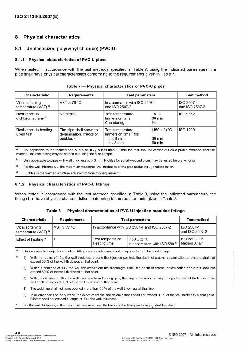
8.1.1 Physical characteristics of PVC-U pipes
When tested in accordance with the test methods specified in Table 7, using the indicated parameters, the pipe shall have physical characteristics conforming to the requirements given in Table 7.
Table 7 — Physical characteristics of PVC-U pipes
Characteristic Requirements Test parameters Test method
Vicat softening temperature (VST) a
VST W 79 °C In accordance with ISO 2507-1 and ISO 2507-2
ISO 2507-1 and ISO 2507-2
Resistance to dichloromethane b
No attack Test temperature Immersion time Chamfering
15 °C 30 min No
ISO 9852
Resistance to heating — Oven test
The pipe shall show no delamination, cracks or bubbles d
Test temperature Immersion time c for: e u 8 mm e > 8 mm
(150 ± 2) °C 30 min 60 min
ISO 12091
a Not applicable to the foamed part of a pipe. If e4 is less than 1,8 mm the test shall be carried out on a profile extruded from thematerial. Indirect testing may be carried out using the pipe sample. b Only applicable to pipes with wall thickness e4 > 3 mm. Profiles for spirally-wound pipes may be tested before winding. c For the wall thickness, e, the maximum measured wall thickness of the pipe excluding ec shall be taken. d Bubbles in the foamed structure are exempt from this requirement.
8.1.2 Physical characteristics of PVC-U fittings
When tested in accordance with the test methods specified in Table 8, using the indicated parameters, the fitting shall have physical characteristics conforming to the requirements given in Table 8.
Table 8 — Physical characteristics of PVC-U injection-moulded fittings
Characteristic Requirements Test parameters Test method
Vicat softening temperature (VST) a
VST W 77 °C In accordance with ISO 2507-1 and ISO 2507-2 ISO 2507-1 and ISO 2507-2
Effect of heating a b Test temperature Heating time
(150 ± 2) °C In accordance with ISO 580 c
ISO 580:2005 Method A, air
a Only applicable to injection-moulded fittings and injection-moulded components for fabricated fittings. b 1) Within a radius of 15 × the wall thickness around the injection point(s), the depth of cracks, delamination or blisters shall not
exceed 50 % of the wall thickness at that point.
2) Within a distance of 10 × the wall thickness from the diaphragm zone, the depth of cracks, delamination or blisters shall not exceed 50 % of the wall thickness at that point.
3) Within a distance of 10 × the wall thickness from the ring gate, the length of cracks running through the overall thickness of the wall shall not exceed 50 % of the wall thickness at that point.
4) The weld line shall not have opened more than 50 % of the wall thickness at that line.
5) In all other parts of the surface, the depth of cracks and delaminations shall not exceed 30 % of the wall thickness at that point. Blisters shall not exceed a length of 10 × the wall thickness.
c For the wall thickness, e, the maximum measured wall thickness of the fitting excluding ec shall be taken.
Copyright International Organization for Standardization Provided by IHS under license with ISO Licensee=IHS Employees/1111111001, User=leee, leee
Not for Resale, 11/22/2007 19:22:36 MSTNo reproduction or networking permitted without license from IHS
--`,```,``,`,,`,`,`,,``,``,`,`,-`-`,,`,,`,`,,`---
ISO 21138-3:2007(E)
© ISO 2007 – All rights reserved 19
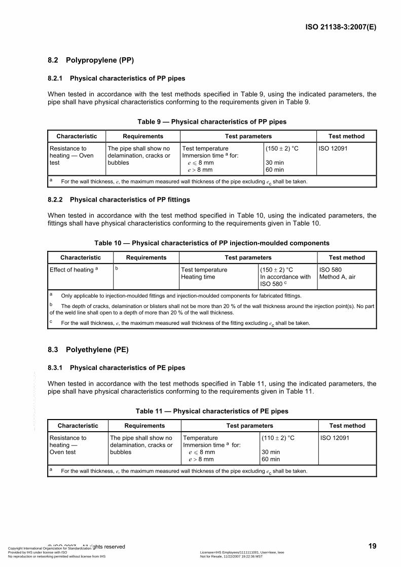
8.2 Polypropylene (PP)
8.2.1 Physical characteristics of PP pipes
When tested in accordance with the test methods specified in Table 9, using the indicated parameters, the pipe shall have physical characteristics conforming to the requirements given in Table 9.
Table 9 — Physical characteristics of PP pipes
Characteristic Requirements Test parameters Test method
Resistance to heating — Oven test
The pipe shall show no delamination, cracks or bubbles
Test temperature Immersion time a for: e u 8 mm e > 8 mm
(150 ± 2) °C 30 min 60 min
ISO 12091
a For the wall thickness, e, the maximum measured wall thickness of the pipe excluding ec shall be taken.
8.2.2 Physical characteristics of PP fittings
When tested in accordance with the test method specified in Table 10, using the indicated parameters, the fittings shall have physical characteristics conforming to the requirements given in Table 10.
Table 10 — Physical characteristics of PP injection-moulded components
Characteristic Requirements Test parameters Test method
Effect of heating a b Test temperature Heating time
(150 ± 2) °C In accordance with ISO 580 c
ISO 580 Method A, air
a Only applicable to injection-moulded fittings and injection-moulded components for fabricated fittings. b The depth of cracks, delamination or blisters shall not be more than 20 % of the wall thickness around the injection point(s). No part of the weld line shall open to a depth of more than 20 % of the wall thickness. c For the wall thickness, e, the maximum measured wall thickness of the fitting excluding ec shall be taken.
8.3 Polyethylene (PE)
8.3.1 Physical characteristics of PE pipes
When tested in accordance with the test methods specified in Table 11, using the indicated parameters, the pipe shall have physical characteristics conforming to the requirements given in Table 11.
Table 11 — Physical characteristics of PE pipes
Characteristic Requirements Test parameters Test method
Resistance to heating — Oven test
The pipe shall show no delamination, cracks or bubbles
Temperature Immersion time a for: e u 8 mm e > 8 mm
(110 ± 2) °C 30 min 60 min
ISO 12091
a For the wall thickness, e, the maximum measured wall thickness of the pipe excluding ec shall be taken.
Copyright International Organization for Standardization Provided by IHS under license with ISO Licensee=IHS Employees/1111111001, User=leee, leee
Not for Resale, 11/22/2007 19:22:36 MSTNo reproduction or networking permitted without license from IHS
--`,```,``,`,,`,`,`,,``,``,`,`,-`-`,,`,,`,`,,`---
ISO 21138-3:2007(E)
20 © ISO 2007 – All rights reserved
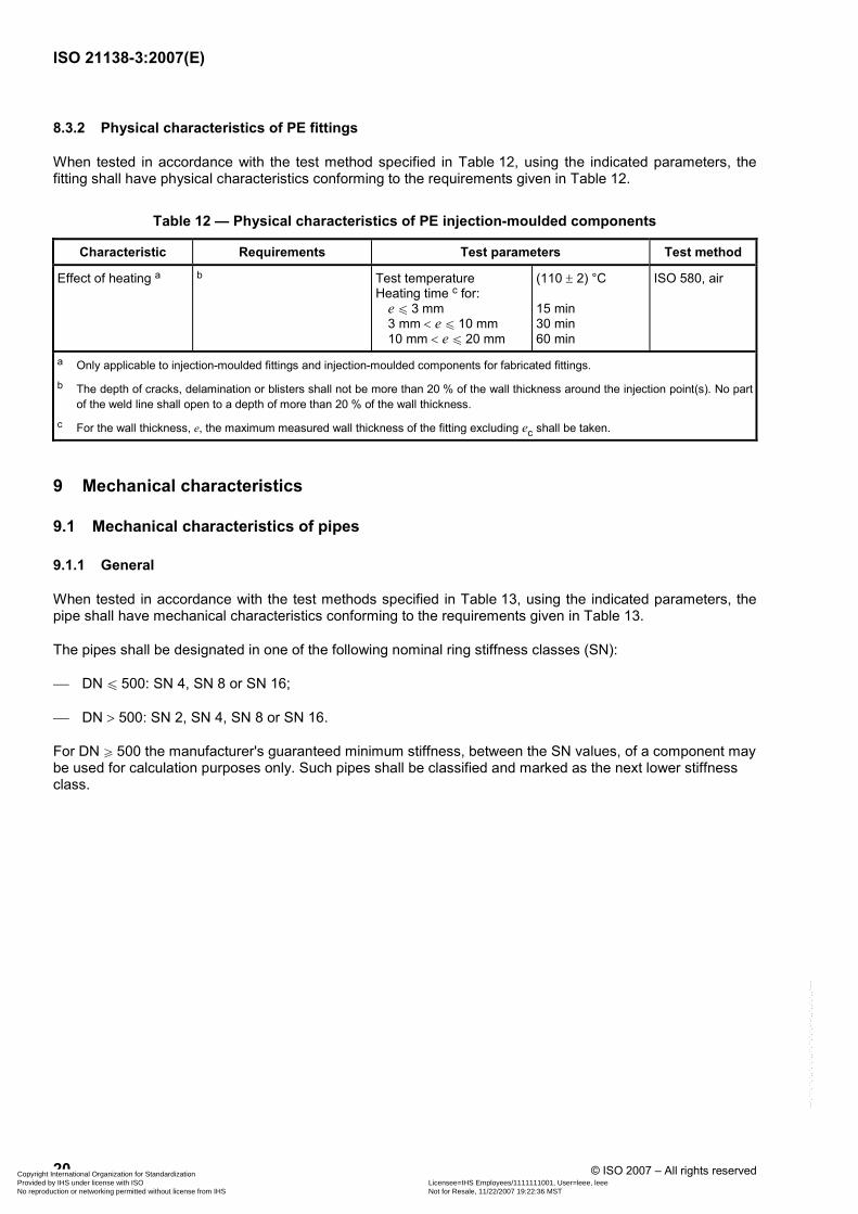
8.3.2 Physical characteristics of PE fittings
When tested in accordance with the test method specified in Table 12, using the indicated parameters, the fitting shall have physical characteristics conforming to the requirements given in Table 12.
Table 12 — Physical characteristics of PE injection-moulded components
Characteristic Requirements Test parameters Test method
Effect of heating a b Test temperature Heating time c for: e u 3 mm 3 mm < e u 10 mm 10 mm < e u 20 mm
(110 ± 2) °C 15 min 30 min 60 min
ISO 580, air
a Only applicable to injection-moulded fittings and injection-moulded components for fabricated fittings. b The depth of cracks, delamination or blisters shall not be more than 20 % of the wall thickness around the injection point(s). No part
of the weld line shall open to a depth of more than 20 % of the wall thickness. c For the wall thickness, e, the maximum measured wall thickness of the fitting excluding ec shall be taken.
9 Mechanical characteristics
9.1 Mechanical characteristics of pipes
9.1.1 General
When tested in accordance with the test methods specified in Table 13, using the indicated parameters, the pipe shall have mechanical characteristics conforming to the requirements given in Table 13.
The pipes shall be designated in one of the following nominal ring stiffness classes (SN):
⎯ DN u 500: SN 4, SN 8 or SN 16;
⎯ DN > 500: SN 2, SN 4, SN 8 or SN 16.
For DN W 500 the manufacturer's guaranteed minimum stiffness, between the SN values, of a component may be used for calculation purposes only. Such pipes shall be classified and marked as the next lower stiffness class.
Copyright International Organization for Standardization Provided by IHS under license with ISO Licensee=IHS Employees/1111111001, User=leee, leee
Not for Resale, 11/22/2007 19:22:36 MSTNo reproduction or networking permitted without license from IHS
--`,```,``,`,,`,`,`,,``,``,`,`,-`-`,,`,,`,`,,`---
ISO 21138-3:2007(E)
© ISO 2007 – All rights reserved 21
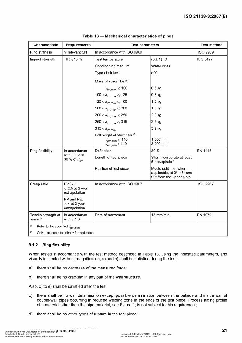
Table 13 — Mechanical characteristics of pipes
Characteristic Requirements Test parameters Test method
Ring stiffness W relevant SN In accordance with ISO 9969 ISO 9969
Impact strength TIR u10 % Test temperature
Conditioning medium
Type of striker Mass of striker for a:
dim,max u 100
100 < dim,max u 125
125 < dim,max u 160
160 < dim,max u 200
200 < dim,max u 250
250 < dim,max u 315
315 < dim,max
Fall height of striker for a: dem,min u 110 dem,min > 110
(0 ± 1) °C
Water or air
d90
0,5 kg
0,8 kg
1,0 kg
1,6 kg
2,0 kg
2,5 kg
3,2 kg
1 600 mm 2 000 mm
ISO 3127
Ring flexibility In accordance with 9.1.2 at 30 % of dem
Deflection
Length of test piece
Position of test piece
30 %
Shall incorporate at least 5 ribs/spirals b
Mould split line, when applicable, at 0°, 45° and 90° from the upper plate
EN 1446
Creep ratio PVC-U: u 2,5 at 2 year extrapolation
PP and PE: u 4 at 2 year extrapolation
In accordance with ISO 9967 ISO 9967
Tensile strength of seam b
In accordance with 9.1.3
Rate of movement 15 mm/min EN 1979
a Refer to the specified dem,min. b Only applicable to spirally formed pipes.
9.1.2 Ring flexibility
When tested in accordance with the test method described in Table 13, using the indicated parameters, and visually inspected without magnification, a) and b) shall be satisfied during the test:
a) there shall be no decrease of the measured force;
b) there shall be no cracking in any part of the wall structure.
Also, c) to e) shall be satisfied after the test:
c) there shall be no wall delamination except possible delamination between the outside and inside wall of double-wall pipes occurring in reduced welding zone in the ends of the test piece. Process aiding profile of a material other than the pipe material, see Figure 1, is not subject to this requirement;
d) there shall be no other types of rupture in the test piece;
Copyright International Organization for Standardization Provided by IHS under license with ISO Licensee=IHS Employees/1111111001, User=leee, leee
Not for Resale, 11/22/2007 19:22:36 MSTNo reproduction or networking permitted without license from IHS
--`,```,``,`,,`,`,`,,``,``,`,`,-`-`,,`,,`,`,,`---
ISO 21138-3:2007(E)
22 © ISO 2007 – All rights reserved
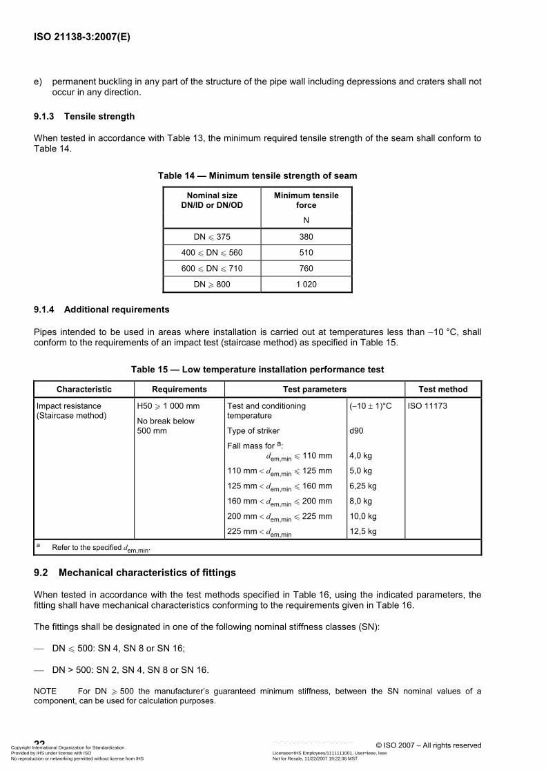
e) permanent buckling in any part of the structure of the pipe wall including depressions and craters shall not occur in any direction.
9.1.3 Tensile strength
When tested in accordance with Table 13, the minimum required tensile strength of the seam shall conform to Table 14.
Table 14 — Minimum tensile strength of seam
Nominal size DN/ID or DN/OD
Minimum tensile force
N
DN u 375 380
400 u DN u 560 510
600 u DN u 710 760
DN W 800 1 020
9.1.4 Additional requirements
Pipes intended to be used in areas where installation is carried out at temperatures less than −10 °C, shall conform to the requirements of an impact test (staircase method) as specified in Table 15.
Table 15 — Low temperature installation performance test
Characteristic Requirements Test parameters Test method
Impact resistance (Staircase method)
H50 W 1 000 mm
No break below 500 mm
Test and conditioning temperature
Type of striker
Fall mass for a: dem,min u 110 mm
110 mm < dem,min u 125 mm
125 mm < dem,min u 160 mm
160 mm < dem,min u 200 mm
200 mm < dem,min u 225 mm
225 mm < dem,min
(−10 ± 1)°C
d90
4,0 kg
5,0 kg
6,25 kg
8,0 kg
10,0 kg
12,5 kg
ISO 11173
a Refer to the specified dem,min.
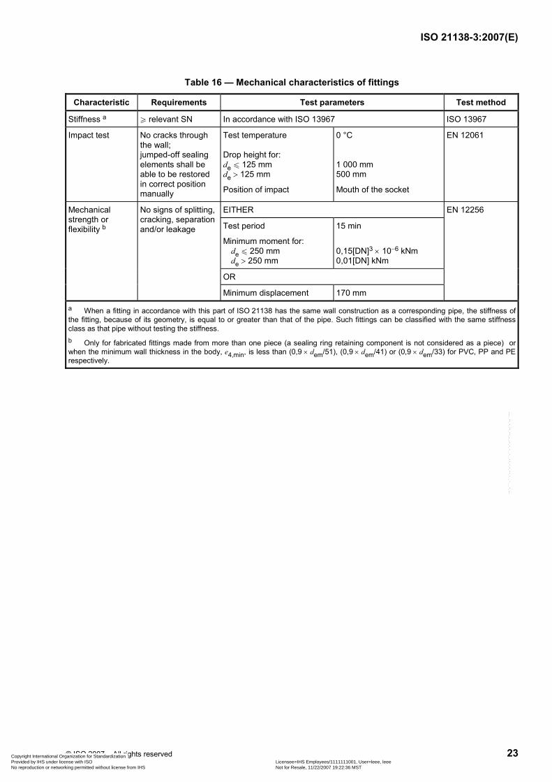
9.2 Mechanical characteristics of fittings
When tested in accordance with the test methods specified in Table 16, using the indicated parameters, the fitting shall have mechanical characteristics conforming to the requirements given in Table 16.
The fittings shall be designated in one of the following nominal stiffness classes (SN):
⎯ DN u 500: SN 4, SN 8 or SN 16;
⎯ DN > 500: SN 2, SN 4, SN 8 or SN 16.
NOTE For DN W 500 the manufacturer’s guaranteed minimum stiffness, between the SN nominal values of a component, can be used for calculation purposes.
Copyright International Organization for Standardization Provided by IHS under license with ISO Licensee=IHS Employees/1111111001, User=leee, leee
Not for Resale, 11/22/2007 19:22:36 MSTNo reproduction or networking permitted without license from IHS
--`,```,``,`,,`,`,`,,``,``,`,`,-`-`,,`,,`,`,,`---
ISO 21138-3:2007(E)
© ISO 2007 – All rights reserved 23
Table 16 — Mechanical characteristics of fittings
Characteristic Requirements Test parameters Test method
Stiffness a W relevant SN In accordance with ISO 13967 ISO 13967
Impact test No cracks through the wall; jumped-off sealing elements shall be able to be restored in correct position manually
Test temperature Drop height for: de u 125 mm de > 125 mm
Position of impact
0 °C 1 000 mm 500 mm
Mouth of the socket
EN 12061
EITHER EN 12256 Mechanical strength or flexibility b
No signs of splitting, cracking, separation and/or leakage Test period
Minimum moment for: de u 250 mm de > 250 mm
15 min
0,15[DN]3 × 10⁻⁶ kNm 0,01[DN] kNm
OR
Minimum displacement 170 mm
a When a fitting in accordance with this part of ISO 21138 has the same wall construction as a corresponding pipe, the stiffness of the fitting, because of its geometry, is equal to or greater than that of the pipe. Such fittings can be classified with the same stiffness class as that pipe without testing the stiffness. b Only for fabricated fittings made from more than one piece (a sealing ring retaining component is not considered as a piece) or when the minimum wall thickness in the body, e4,min, is less than (0,9 × dem/51), (0,9 × dem/41) or (0,9 × dem/33) for PVC, PP and PE respectively.
Copyright International Organization for Standardization Provided by IHS under license with ISO Licensee=IHS Employees/1111111001, User=leee, leee
Not for Resale, 11/22/2007 19:22:36 MSTNo reproduction or networking permitted without license from IHS
--`,```,``,`,,`,`,`,,``,``,`,`,-`-`,,`,,`,`,,`---
ISO 21138-3:2007(E)
24 © ISO 2007 – All rights reserved
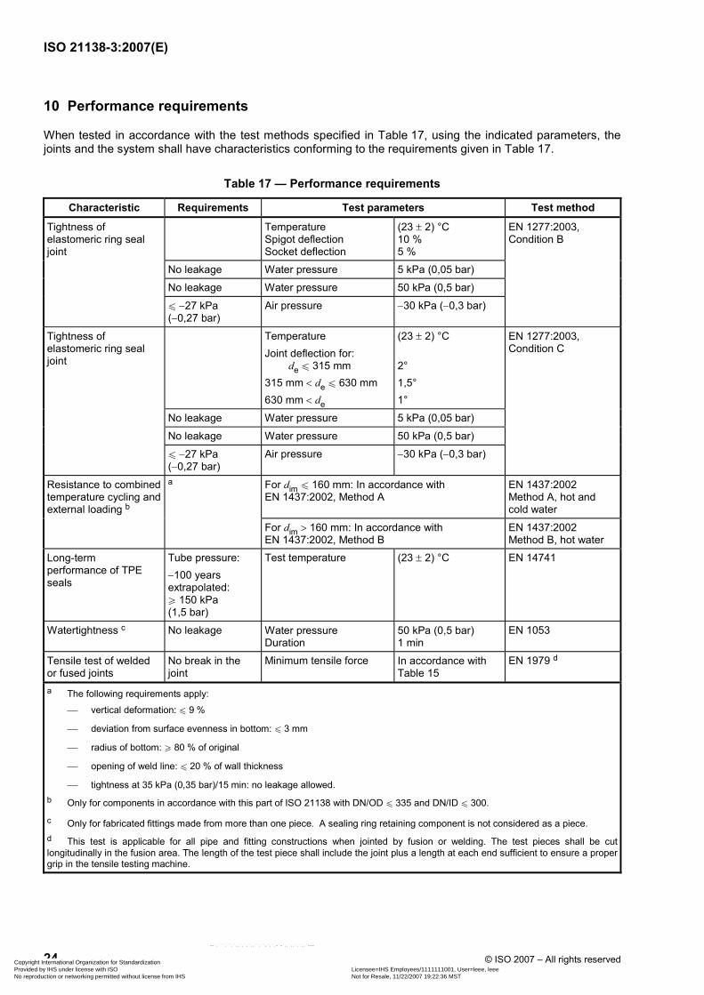
10 Performance requirements
When tested in accordance with the test methods specified in Table 17, using the indicated parameters, the joints and the system shall have characteristics conforming to the requirements given in Table 17.
Table 17 — Performance requirements
Characteristic Requirements Test parameters Test method
Temperature Spigot deflection Socket deflection
(23 ± 2) °C 10 % 5 %
No leakage Water pressure 5 kPa (0,05 bar)
No leakage Water pressure 50 kPa (0,5 bar)
Tightness of elastomeric ring seal joint
u −27 kPa (−0,27 bar)
Air pressure −30 kPa (−0,3 bar)
EN 1277:2003, Condition B
Temperature Joint deflection for: de u 315 mm 315 mm < de u 630 mm 630 mm < de
(23 ± 2) °C 2° 1,5° 1°
No leakage Water pressure 5 kPa (0,05 bar)
No leakage Water pressure 50 kPa (0,5 bar)
Tightness of elastomeric ring seal joint
u −27 kPa (−0,27 bar)
Air pressure −30 kPa (−0,3 bar)
EN 1277:2003, Condition C
a For dim u 160 mm: In accordance with EN 1437:2002, Method A
EN 1437:2002 Method A, hot and cold water
Resistance to combined temperature cycling and external loading b
For dim > 160 mm: In accordance with EN 1437:2002, Method B
EN 1437:2002 Method B, hot water
Long-term performance of TPE seals
Tube pressure: −100 years extrapolated: W 150 kPa (1,5 bar)
Test temperature (23 ± 2) °C EN 14741
Watertightness c No leakage Water pressure Duration
50 kPa (0,5 bar) 1 min
EN 1053
Tensile test of welded or fused joints
No break in the joint
Minimum tensile force In accordance with Table 15
EN 1979 d
a The following requirements apply:
⎯ vertical deformation: u 9 %
⎯ deviation from surface evenness in bottom: u 3 mm
⎯ radius of bottom: W 80 % of original
⎯ opening of weld line: u 20 % of wall thickness
⎯ tightness at 35 kPa (0,35 bar)/15 min: no leakage allowed. b Only for components in accordance with this part of ISO 21138 with DN/OD u 335 and DN/ID u 300.
c Only for fabricated fittings made from more than one piece. A sealing ring retaining component is not considered as a piece. d This test is applicable for all pipe and fitting constructions when jointed by fusion or welding. The test pieces shall be cut longitudinally in the fusion area. The length of the test piece shall include the joint plus a length at each end sufficient to ensure a proper grip in the tensile testing machine.
Copyright International Organization for Standardization Provided by IHS under license with ISO Licensee=IHS Employees/1111111001, User=leee, leee
Not for Resale, 11/22/2007 19:22:36 MSTNo reproduction or networking permitted without license from IHS
--`,```,``,`,,`,`,`,,``,``,`,`,-`-`,,`,,`,`,,`---
ISO 21138-3:2007(E)
© ISO 2007 – All rights reserved 25
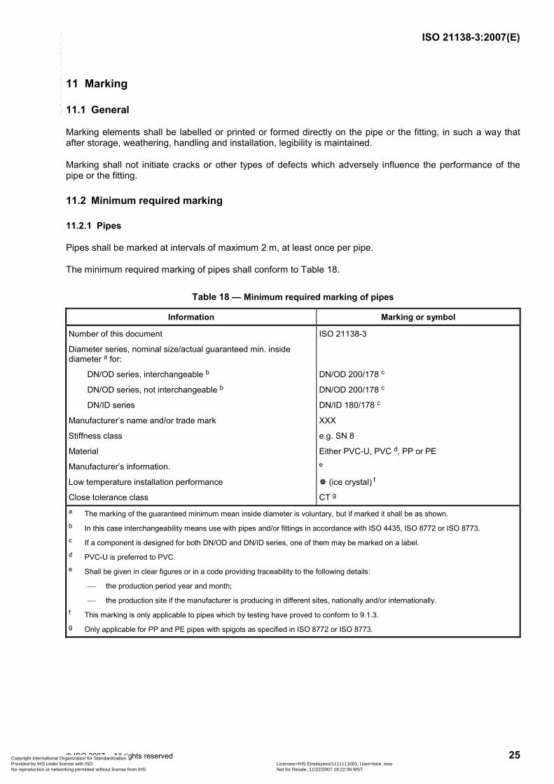
11 Marking
11.1 General
Marking elements shall be labelled or printed or formed directly on the pipe or the fitting, in such a way that after storage, weathering, handling and installation, legibility is maintained.
Marking shall not initiate cracks or other types of defects which adversely influence the performance of the pipe or the fitting.
11.2 Minimum required marking
11.2.1 Pipes
Pipes shall be marked at intervals of maximum 2 m, at least once per pipe.
The minimum required marking of pipes shall conform to Table 18.
Table 18 — Minimum required marking of pipes
Information Marking or symbol
Number of this document
Diameter series, nominal size/actual guaranteed min. inside diameter a for:
DN/OD series, interchangeable b
DN/OD series, not interchangeable b
DN/ID series
Manufacturer’s name and/or trade mark
Stiffness class
Material
Manufacturer’s information.
Low temperature installation performance
Close tolerance class
ISO 21138-3
DN/OD 200/178 c
DN/OD 200/178 c
DN/ID 180/178 c
XXX
e.g. SN 8
Either PVC-U, PVC d, PP or PE e
(ice crystal) f
CT g a The marking of the guaranteed minimum mean inside diameter is voluntary, but if marked it shall be as shown. b In this case interchangeability means use with pipes and/or fittings in accordance with ISO 4435, ISO 8772 or ISO 8773. c If a component is designed for both DN/OD and DN/ID series, one of them may be marked on a label. d PVC-U is preferred to PVC. e Shall be given in clear figures or in a code providing traceability to the following details:
⎯ the production period year and month;
⎯ the production site if the manufacturer is producing in different sites, nationally and/or internationally. f This marking is only applicable to pipes which by testing have proved to conform to 9.1.3. g Only applicable for PP and PE pipes with spigots as specified in ISO 8772 or ISO 8773.
Copyright International Organization for Standardization Provided by IHS under license with ISO Licensee=IHS Employees/1111111001, User=leee, leee
Not for Resale, 11/22/2007 19:22:36 MSTNo reproduction or networking permitted without license from IHS
--`,```,``,`,,`,`,`,,``,``,`,`,-`-`,,`,,`,`,,`---
ISO 21138-3:2007(E)
26 © ISO 2007 – All rights reserved
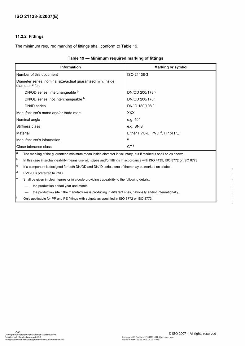
11.2.2 Fittings
The minimum required marking of fittings shall conform to Table 19.
Table 19 — Minimum required marking of fittings
Information Marking or symbol
Number of this document
Diameter series, nominal size/actual guaranteed min. inside diameter a for:
DN/OD series, interchangeable b
DN/OD series, not interchangeable b
DN/ID series
Manufacturer’s name and/or trade mark
Nominal angle
Stiffness class
Material
Manufacturer’s information
Close tolerance class
ISO 21138-3
DN/OD 200/178 c
DN/OD 200/178 c
DN/ID 180/198 c
XXX
e.g. 45°
e.g. SN 8
Either PVC-U, PVC d, PP or PE e
CT f a The marking of the guaranteed minimum mean inside diameter is voluntary, but if marked it shall be as shown. b In this case interchangeability means use with pipes and/or fittings in accordance with ISO 4435, ISO 8772 or ISO 8773. c If a component is designed for both DN/OD and DN/ID series, one of them may be marked on a label. d PVC-U is preferred to PVC. e Shall be given in clear figures or in a code providing traceability to the following details:
⎯ the production period year and month;
⎯ the production site if the manufacturer is producing in different sites, nationally and/or internationally. f Only applicable for PP and PE fittings with spigots as specified in ISO 8772 or ISO 8773.
Copyright International Organization for Standardization Provided by IHS under license with ISO Licensee=IHS Employees/1111111001, User=leee, leee
Not for Resale, 11/22/2007 19:22:36 MSTNo reproduction or networking permitted without license from IHS
--`,```,``,`,,`,`,`,,``,``,`,`,-`-`,,`,,`,`,,`---
ISO 21138-3:2007(E)
© ISO 2007 – All rights reserved 27
Annex A (normative)
Virgin PVC-U material
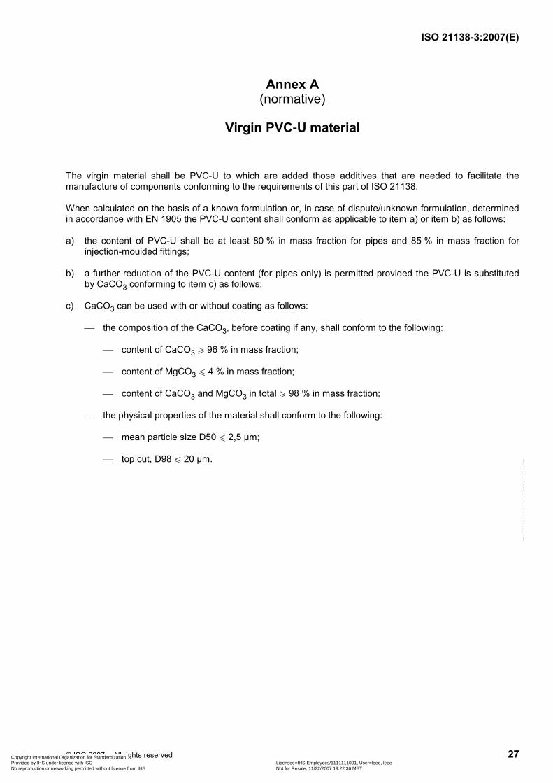
The virgin material shall be PVC-U to which are added those additives that are needed to facilitate the manufacture of components conforming to the requirements of this part of ISO 21138.
When calculated on the basis of a known formulation or, in case of dispute/unknown formulation, determined in accordance with EN 1905 the PVC-U content shall conform as applicable to item a) or item b) as follows:
a) the content of PVC-U shall be at least 80 % in mass fraction for pipes and 85 % in mass fraction for injection-moulded fittings;
b) a further reduction of the PVC-U content (for pipes only) is permitted provided the PVC-U is substituted by CaCO3 conforming to item c) as follows;
c) CaCO3 can be used with or without coating as follows:
⎯ the composition of the CaCO3, before coating if any, shall conform to the following:
⎯ content of CaCO3 W 96 % in mass fraction;
⎯ content of MgCO3 u 4 % in mass fraction;
⎯ content of CaCO3 and MgCO3 in total W 98 % in mass fraction;
⎯ the physical properties of the material shall conform to the following:
⎯ mean particle size D50 u 2,5 µm;
⎯ top cut, D98 u 20 µm.
Copyright International Organization for Standardization Provided by IHS under license with ISO Licensee=IHS Employees/1111111001, User=leee, leee
Not for Resale, 11/22/2007 19:22:36 MSTNo reproduction or networking permitted without license from IHS
--`,```,``,`,,`,`,`,,``,``,`,`,-`-`,,`,,`,`,,`---
ISO 21138-3:2007(E)
28 © ISO 2007 – All rights reserved
Annex B (normative)
Utilization of non-virgin PVC-U material
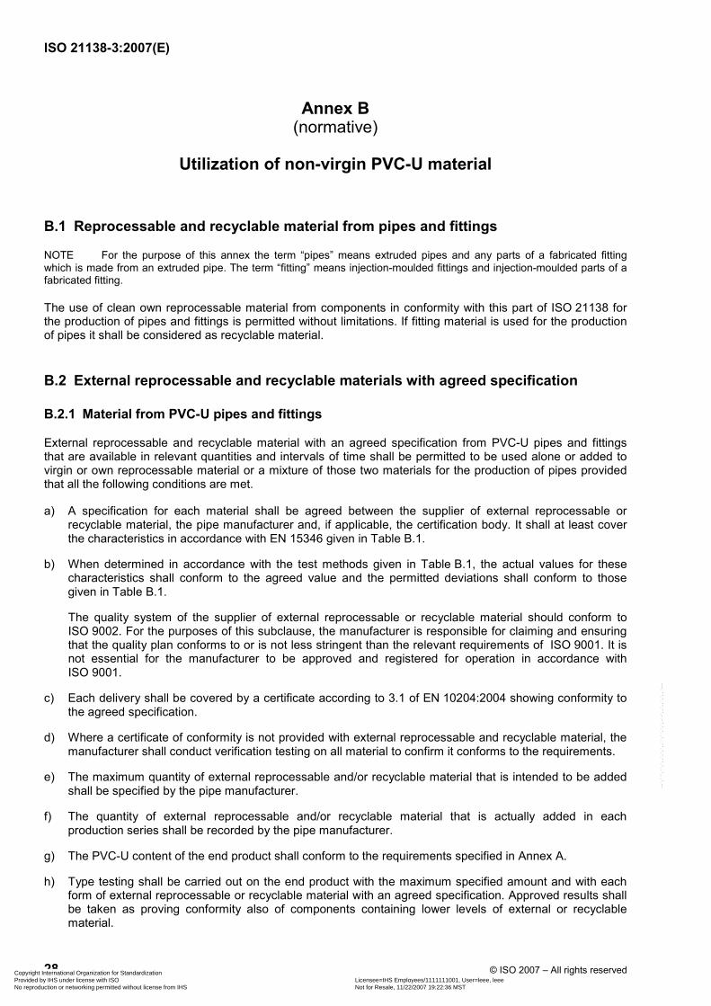
B.1 Reprocessable and recyclable material from pipes and fittings
NOTE For the purpose of this annex the term “pipes” means extruded pipes and any parts of a fabricated fitting which is made from an extruded pipe. The term “fitting” means injection-moulded fittings and injection-moulded parts of a fabricated fitting.
The use of clean own reprocessable material from components in conformity with this part of ISO 21138 for the production of pipes and fittings is permitted without limitations. If fitting material is used for the production of pipes it shall be considered as recyclable material.
B.2 External reprocessable and recyclable materials with agreed specification
B.2.1 Material from PVC-U pipes and fittings
External reprocessable and recyclable material with an agreed specification from PVC-U pipes and fittings that are available in relevant quantities and intervals of time shall be permitted to be used alone or added to virgin or own reprocessable material or a mixture of those two materials for the production of pipes provided that all the following conditions are met.
a) A specification for each material shall be agreed between the supplier of external reprocessable or recyclable material, the pipe manufacturer and, if applicable, the certification body. It shall at least cover the characteristics in accordance with EN 15346 given in Table B.1.
b) When determined in accordance with the test methods given in Table B.1, the actual values for these characteristics shall conform to the agreed value and the permitted deviations shall conform to those given in Table B.1.
The quality system of the supplier of external reprocessable or recyclable material should conform to ISO 9002. For the purposes of this subclause, the manufacturer is responsible for claiming and ensuring that the quality plan conforms to or is not less stringent than the relevant requirements of ISO 9001. It is not essential for the manufacturer to be approved and registered for operation in accordance with ISO 9001.
c) Each delivery shall be covered by a certificate according to 3.1 of EN 10204:2004 showing conformity to the agreed specification.
d) Where a certificate of conformity is not provided with external reprocessable and recyclable material, the manufacturer shall conduct verification testing on all material to confirm it conforms to the requirements.
e) The maximum quantity of external reprocessable and/or recyclable material that is intended to be added shall be specified by the pipe manufacturer.
f) The quantity of external reprocessable and/or recyclable material that is actually added in each production series shall be recorded by the pipe manufacturer.
g) The PVC-U content of the end product shall conform to the requirements specified in Annex A.
h) Type testing shall be carried out on the end product with the maximum specified amount and with each form of external reprocessable or recyclable material with an agreed specification. Approved results shall be taken as proving conformity also of components containing lower levels of external or recyclable material.
Copyright International Organization for Standardization Provided by IHS under license with ISO Licensee=IHS Employees/1111111001, User=leee, leee
Not for Resale, 11/22/2007 19:22:36 MSTNo reproduction or networking permitted without license from IHS
--`,```,``,`,,`,`,`,,``,``,`,`,-`-`,,`,,`,`,,`---
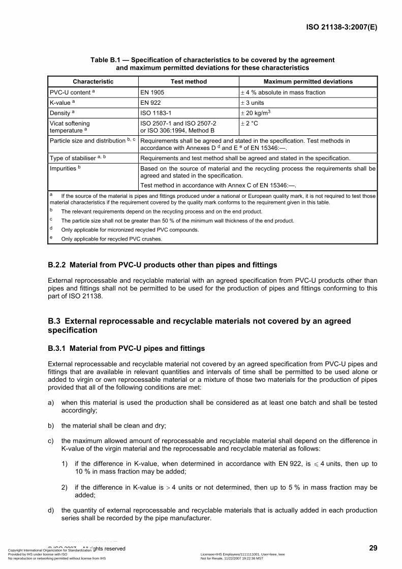
ISO 21138-3:2007(E)
© ISO 2007 – All rights reserved 29
Table B.1 — Specification of characteristics to be covered by the agreement and maximum permitted deviations for these characteristics
Characteristic Test method Maximum permitted deviations
PVC-U content a EN 1905 ± 4 % absolute in mass fraction
K-value a EN 922 ± 3 units
Density a ISO 1183-1 ± 20 kg/m3
Vicat softening temperature a
ISO 2507-1 and ISO 2507-2 or ISO 306:1994, Method B
± 2 °C
Particle size and distribution b, c Requirements shall be agreed and stated in the specification. Test methods in accordance with Annexes D d and E e of EN 15346:—.
Type of stabiliser a, b Requirements and test method shall be agreed and stated in the specification.
Impurities b Based on the source of material and the recycling process the requirements shall be agreed and stated in the specification. Test method in accordance with Annex C of EN 15346:—.
a If the source of the material is pipes and fittings produced under a national or European quality mark, it is not required to test those material characteristics if the requirement covered by the quality mark conforms to the requirement given in this table. b The relevant requirements depend on the recycling process and on the end product. c The particle size shall not be greater than 50 % of the minimum wall thickness of the end product. d Only applicable for micronized recycled PVC compounds. e Only applicable for recycled PVC crushes.
B.2.2 Material from PVC-U products other than pipes and fittings
External reprocessable and recyclable material with an agreed specification from PVC-U products other than pipes and fittings shall not be permitted to be used for the production of pipes and fittings conforming to this part of ISO 21138.
B.3 External reprocessable and recyclable materials not covered by an agreed specification
B.3.1 Material from PVC-U pipes and fittings
External reprocessable and recyclable material not covered by an agreed specification from PVC-U pipes and fittings that are available in relevant quantities and intervals of time shall be permitted to be used alone or added to virgin or own reprocessable material or a mixture of those two materials for the production of pipes provided that all of the following conditions are met:
a) when this material is used the production shall be considered as at least one batch and shall be tested accordingly;
b) the material shall be clean and dry;
c) the maximum allowed amount of reprocessable and recyclable material shall depend on the difference in K-value of the virgin material and the reprocessable and recyclable material as follows:
1) if the difference in K-value, when determined in accordance with EN 922, is u 4 units, then up to 10 % in mass fraction may be added;
2) if the difference in K-value is > 4 units or not determined, then up to 5 % in mass fraction may be added;
d) the quantity of external reprocessable and recyclable materials that is actually added in each production series shall be recorded by the pipe manufacturer.
Copyright International Organization for Standardization Provided by IHS under license with ISO Licensee=IHS Employees/1111111001, User=leee, leee
Not for Resale, 11/22/2007 19:22:36 MSTNo reproduction or networking permitted without license from IHS
--`,```,``,`,,`,`,`,,``,``,`,`,-`-`,,`,,`,`,,`---
ISO 21138-3:2007(E)
30 © ISO 2007 – All rights reserved
B.3.2 Material from PVC-U products other than pipes and fittings
External reprocessable and/or recyclable material not covered by an agreed specification from PVC-U products other than pipes and fittings shall not be used for the production of pipes and fittings conforming to this part of ISO 21138.
Copyright International Organization for Standardization Provided by IHS under license with ISO Licensee=IHS Employees/1111111001, User=leee, leee
Not for Resale, 11/22/2007 19:22:36 MSTNo reproduction or networking permitted without license from IHS
--`,```,``,`,,`,`,`,,``,``,`,`,-`-`,,`,,`,`,,`---
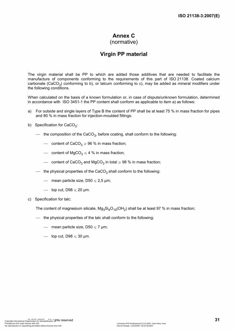
ISO 21138-3:2007(E)
© ISO 2007 – All rights reserved 31
Annex C (normative)
Virgin PP material
The virgin material shall be PP to which are added those additives that are needed to facilitate the manufacture of components conforming to the requirements of this part of ISO 21138. Coated calcium carbonate (CaCO3) conforming to b), or talcum conforming to c), may be added as mineral modifiers under the following conditions.
When calculated on the basis of a known formulation or, in case of dispute/unknown formulation, determined in accordance with ISO 3451-1 the PP content shall conform as applicable to item a) as follows:
a) For outside and single layers of Type B the content of PP shall be at least 75 % in mass fraction for pipes and 80 % in mass fraction for injection-moulded fittings.
b) Specification for CaCO3:
⎯ the composition of the CaCO3, before coating, shall conform to the following:
⎯ content of CaCO3 W 96 % in mass fraction;
⎯ content of MgCO3 u 4 % in mass fraction;
⎯ content of CaCO3 and MgCO3 in total W 98 % in mass fraction;
⎯ the physical properties of the CaCO3 shall conform to the following:
⎯ mean particle size, D50 u 2,5 µm;
⎯ top cut, D98 u 20 µm.
c) Specification for talc:
The content of magnesium silicate, Mg3Si4O10(OH2) shall be at least 97 % in mass fraction;
⎯ the physical properties of the talc shall conform to the following:
⎯ mean particle size, D50 u 7 µm;
⎯ top cut, D98 u 30 µm.
Copyright International Organization for Standardization Provided by IHS under license with ISO Licensee=IHS Employees/1111111001, User=leee, leee
Not for Resale, 11/22/2007 19:22:36 MSTNo reproduction or networking permitted without license from IHS
--`,```,``,`,,`,`,`,,``,``,`,`,-`-`,,`,,`,`,,`---
ISO 21138-3:2007(E)
32 © ISO 2007 – All rights reserved
Annex D (normative)
Utilization of non-virgin PP material
D.1 Reprocessable and recyclable material from pipes and fittings
NOTE For the purpose of this annex the term “pipes” means extruded pipes and any parts of a fabricated fitting which is made from an extruded pipe. The term “fitting” means injection-moulded fittings and injection-moulded parts of a fabricated fitting.
The use of clean own reprocessable material of components conforming to this part of ISO 21138 for the production of pipes and fittings is permitted without limitations.
D.2 External reprocessable and recyclable materials with an agreed specification
D.2.1 Material from PP pipes and fittings
External reprocessable and recyclable materials with an agreed specification from PP pipes and fittings that are available in relevant quantities and intervals of time shall be permitted to be used alone or added to virgin or own reprocessable material or a mixture of those two materials for the production of pipes (and fittings, if relevant) provided all of the following conditions are met.
a) A specification for each material shall be agreed upon between the supplier of external reprocessable or recyclable material, the pipe manufacturer and, if applicable, the certification body. It shall at least cover the characteristics in accordance with EN 15345 given in Table D.1.
b) When determined in accordance with the test methods given in Table D.1, the actual values for these characteristics shall conform to the agreed value and the permitted deviations shall conform to those given in Table D.1.
The quality system of the supplier of external reprocessable or recyclable material should conform to ISO 9002. For the purposes of this subclause, the manufacturer is responsible for claiming and ensuring that the quality plan conforms to or is no less stringent than the relevant requirements of ISO 9001. It is not essential for the manufacturer to be approved and registered for operation in accordance with ISO 9001.
c) Each delivery shall be covered by a certificate according to 3.1 of EN 10204:2004, showing conformity to the agreed specification.
d) Where a certificate of conformity is not provided with external reprocessable and recyclable material, the manufacturer shall conduct verification testing on all material to confirm it conforms to the requirements.
e) The maximum quantity of external reprocessable and/or recyclable material that is intended to be added shall be specified by the manufacturer.
f) The quantity of external reprocessable and/or recyclable material that is actually added in each production series shall be recorded by the manufacturer.
g) The material of the end product shall conform to the requirements as specified in 4.3 and Annex C except as per D.2.1 h).
h) The material shall be clean and free from visible contamination. Material filtering during pelletizing or extrusion shall be carried out.
Copyright International Organization for Standardization Provided by IHS under license with ISO Licensee=IHS Employees/1111111001, User=leee, leee
Not for Resale, 11/22/2007 19:22:36 MSTNo reproduction or networking permitted without license from IHS
--`,```,``,`,,`,`,`,,``,``,`,`,-`-`,,`,,`,`,,`---
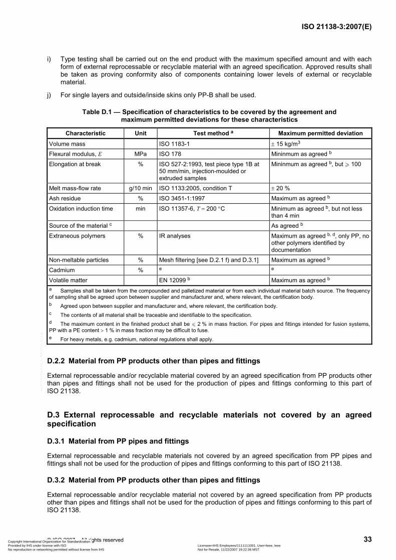
ISO 21138-3:2007(E)
© ISO 2007 – All rights reserved 33
i) Type testing shall be carried out on the end product with the maximum specified amount and with each form of external reprocessable or recyclable material with an agreed specification. Approved results shall be taken as proving conformity also of components containing lower levels of external or recyclable material.
j) For single layers and outside/inside skins only PP-B shall be used.
Table D.1 — Specification of characteristics to be covered by the agreement and maximum permitted deviations for these characteristics
Characteristic Unit Test method a Maximum permitted deviation
Volume mass ISO 1183-1 ± 15 kg/m3
Flexural modulus, E MPa ISO 178 Mininmum as agreed b
Elongation at break % ISO 527-2:1993, test piece type 1B at 50 mm/min, injection-moulded or extruded samples
Mininmum as agreed b, but W 100
Melt mass-flow rate g/10 min ISO 1133:2005, condition T ± 20 %
Ash residue % ISO 3451-1:1997 Maximum as agreed b
Oxidation induction time min ISO 11357-6, T = 200 °C Minimum as agreed b, but not less than 4 min
Source of the material c As agreed b
Extraneous polymers % IR analyses Maximum as agreed b, d, only PP, no other polymers identified by documentation
Non-meltable particles % Mesh filtering [see D.2.1 f) and D.3.1] Maximum as agreed b
Cadmium % e e
Volatile matter EN 12099 b Maximum as agreed b a Samples shall be taken from the compounded and palletized material or from each individual material batch source. The frequency of sampling shall be agreed upon between supplier and manufacturer and, where relevant, the certification body. b Agreed upon between supplier and manufacturer and, where relevant, the certification body. c The contents of all material shall be traceable and identifiable to the specification. d The maximum content in the finished product shall be u 2 % in mass fraction. For pipes and fittings intended for fusion systems,PP with a PE content > 1 % in mass fraction may be difficult to fuse. e For heavy metals, e.g. cadmium, national regulations shall apply.
D.2.2 Material from PP products other than pipes and fittings
External reprocessable and/or recyclable material covered by an agreed specification from PP products other than pipes and fittings shall not be used for the production of pipes and fittings conforming to this part of ISO 21138.
D.3 External reprocessable and recyclable materials not covered by an agreed specification
D.3.1 Material from PP pipes and fittings
External reprocessable and recyclable materials not covered by an agreed specification from PP pipes and fittings shall not be used for the production of pipes and fittings conforming to this part of ISO 21138.
D.3.2 Material from PP products other than pipes and fittings
External reprocessable and/or recyclable material not covered by an agreed specification from PP products other than pipes and fittings shall not be used for the production of pipes and fittings conforming to this part of ISO 21138.
Copyright International Organization for Standardization Provided by IHS under license with ISO Licensee=IHS Employees/1111111001, User=leee, leee
Not for Resale, 11/22/2007 19:22:36 MSTNo reproduction or networking permitted without license from IHS
--`,```,``,`,,`,`,`,,``,``,`,`,-`-`,,`,,`,`,,`---
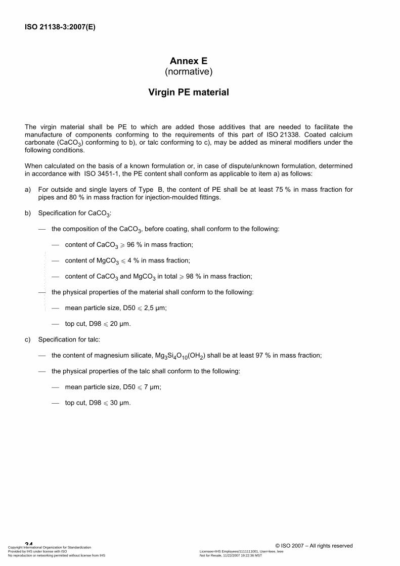
ISO 21138-3:2007(E)
34 © ISO 2007 – All rights reserved
Annex E (normative)
Virgin PE material
The virgin material shall be PE to which are added those additives that are needed to facilitate the manufacture of components conforming to the requirements of this part of ISO 21338. Coated calcium carbonate (CaCO3) conforming to b), or talc conforming to c), may be added as mineral modifiers under the following conditions.
When calculated on the basis of a known formulation or, in case of dispute/unknown formulation, determined in accordance with ISO 3451-1, the PE content shall conform as applicable to item a) as follows:
a) For outside and single layers of Type B, the content of PE shall be at least 75 % in mass fraction for pipes and 80 % in mass fraction for injection-moulded fittings.
b) Specification for CaCO3:
⎯ the composition of the CaCO3, before coating, shall conform to the following:
⎯ content of CaCO3 W 96 % in mass fraction;
⎯ content of MgCO3 u 4 % in mass fraction;
⎯ content of CaCO3 and MgCO3 in total W 98 % in mass fraction;
⎯ the physical properties of the material shall conform to the following:
⎯ mean particle size, D50 u 2,5 µm;
⎯ top cut, D98 u 20 µm.
c) Specification for talc:
⎯ the content of magnesium silicate, Mg3Si4O10(OH2) shall be at least 97 % in mass fraction;
⎯ the physical properties of the talc shall conform to the following:
⎯ mean particle size, D50 u 7 µm;
⎯ top cut, D98 u 30 µm.
Copyright International Organization for Standardization Provided by IHS under license with ISO Licensee=IHS Employees/1111111001, User=leee, leee
Not for Resale, 11/22/2007 19:22:36 MSTNo reproduction or networking permitted without license from IHS
--`,```,``,`,,`,`,`,,``,``,`,`,-`-`,,`,,`,`,,`---
ISO 21138-3:2007(E)
© ISO 2007 – All rights reserved 35
Annex F (normative)
Utilization of non-virgin PE material
F.1 Reprocessable and recyclable material from pipes and fittings
NOTE For the purpose of this annex the term “pipes” means extruded pipes and any parts of a fabricated fitting, which is made from an extruded pipe. The term “fitting” means injection-moulded fittings and injection-moulded parts of a fabricated fitting.
The use of clean own reprocessable material from components complying with this part of ISO 21138 for the production of pipes and fittings shall be permitted without limitations.
F.2 External reprocessable and recyclable materials with an agreed specification
F.2.1 Material from PE pipes and injection-moulded fittings
External reprocessable and recyclable materials with an agreed specification from PE pipes and injection-moulded fittings that are available in relevant quantities and intervals of time may be used alone or added to virgin or own reprocessable materials or a mixture of those two materials for the production of pipes (and injection-moulded fittings, if relevant) provided all of the following conditions are met.
a) A specification for each material shall be agreed upon between the supplier of external reprocessable or recyclable material, the pipe manufacturer and, if applicable, the certification body. It shall at least cover the characteristics in accordance with EN 15344 given in Table F.1.
b) When determined in accordance with the test methods given in Table F.1, the actual values for these characteristics shall conform to the agreed value and the permitted deviations shall conform to those given in Table F.1.
The quality system of the supplier of external reprocessable or recyclable material should conform to ISO 9002. For the purposes of this subclause, the manufacturer is responsible for claiming and ensuring that the quality plan conforms to or is no less stringent than the relevant requirements of ISO 9001. It is not essential for the manufacturer to be approved and registered for operation in accordance with ISO 9001.
c) Each delivery shall be covered by a certificate according to 3.1 of EN 10204:2004 showing conformity to the agreed specification.
d) Where a certificate of conformity is not provided with external reprocessable and recyclable material, the manufacturer shall conduct verification testing on all material to confirm it conforms to the requirements.
e) The maximum quantity of external reprocessable and/or recyclable material that is intended to be added shall be specified by the manufacturer.
f) The quantity of external reprocessable and/or recyclable material that is actually added in each production series shall be recorded by the manufacturer.
g) The material of the end product shall conform to the requirements as specified in 4.4 and Annex E.
h) The material shall be clean and free from visible contamination. Material filtering during pelletizing or extrusion shall be carried out.
Copyright International Organization for Standardization Provided by IHS under license with ISO Licensee=IHS Employees/1111111001, User=leee, leee
Not for Resale, 11/22/2007 19:22:36 MSTNo reproduction or networking permitted without license from IHS
--`,```,``,`,,`,`,`,,``,``,`,`,-`-`,,`,,`,`,,`---
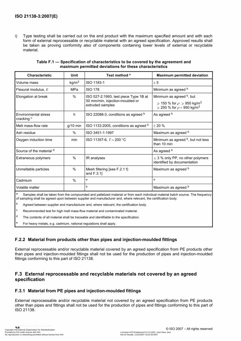
ISO 21138-3:2007(E)
36 © ISO 2007 – All rights reserved
i) Type testing shall be carried out on the end product with the maximum specified amount and with each form of external reprocessable or recyclable material with an agreed specification. Approved results shall be taken as proving conformity also of components containing lower levels of external or recyclable material.
Table F.1 — Specification of characteristics to be covered by the agreement and maximum permitted deviations for these characteristics
Characteristic Unit Test method a Maximum permitted deviation
Volume mass kg/m3 ISO 1183-1 ± 5
Flexural modulus, E MPa ISO 178 Minimum as agreed b
Elongation at break % ISO 527-2:1993, test piece Type 1B at 50 mm/min, injection-moulded or extruded samples
Minimum as agreed b, but
W 150 % for ρ W 950 kg/m3 W 250 % for ρ < 950 kg/m3
Environmental stress cracking c
h ISO 22088-3, conditions as agreed b As agreed b
Melt mass-flow rate g/10 min ISO 1133:2005, conditions as agreed b ± 20 %
Ash residue % ISO 3451-1:1997 Maximum as agreed b
Oxygen induction time min ISO 11357-6, T = 200 °C Minimum as agreed b, but not less than 10 min
Source of the material d As agreed b
Extraneous polymers % IR analyses u 3 % only PP, no other polymers identified by documentation
Unmeltable particles % Mesh filtering [see F.2.1 f) and F.3.1]
Maximum as agreed b
Cadmium % e e
Volatile matter b Maximum as agreed b a Samples shall be taken from the compounded and palletized material or from each individual material batch source. The frequency of sampling shall be agreed upon between supplier and manufacturer and, where relevant, the certification body. b Agreed between supplier and manufacturer and, where relevant, the certification body. c Recommended test for high melt mass-flow material and contaminated material. d The contents of all material shall be traceable and identifiable to the specification. e For heavy metals, e.g. cadmium, national regulations shall apply.
F.2.2 Material from products other than pipes and injection-moulded fittings
External reprocessable and/or recyclable material covered by an agreed specification from PE products other than pipes and injection-moulded fittings shall not be used for the production of pipes and injection-moulded fittings conforming to this part of ISO 21138.
F.3 External reprocessable and recyclable materials not covered by an agreed specification
F.3.1 Material from PE pipes and injection-moulded fittings
External reprocessable and/or recyclable material not covered by an agreed specification from PE products other than pipes and fittings shall not be used for the production of pipes and fittings conforming to this part of ISO 21138.
Copyright International Organization for Standardization Provided by IHS under license with ISO Licensee=IHS Employees/1111111001, User=leee, leee
Not for Resale, 11/22/2007 19:22:36 MSTNo reproduction or networking permitted without license from IHS
--`,```,``,`,,`,`,`,,``,``,`,`,-`-`,,`,,`,`,,`---
ISO 21138-3:2007(E)
© ISO 2007 – All rights reserved 37
F.3.2 Material from PE products other than pipes and injection-moulded fittings
External reprocessable and/or recyclable material not covered by an agreed specification from PE products other than pipes and injection-moulded fittings shall not be used for the production of pipes and injection-moulded fittings conforming to this part of ISO 21138.
F.4 External reprocessable and recyclable material from PE rotational-moulded fittings and other components
External reprocessable and recyclable materials of PE from
⎯ rotational-moulded fittings covered or not covered by an agreed specification,
⎯ other rotational moulded components covered by an agreed specification
that are available in relevant quantities and intervals of time shall be permitted to be added to virgin or own reprocessable material for the production of rotational-moulded fittings only provided all of the following conditions are met:
a) up to 5 % in mass fraction may be used;
b) when this material is used, the production shall be considered as at least one batch and shall be tested accordingly;
c) when determined in accordance with Table F.1, the melt mass-flow rate of the material shall not deviate more than 20 % from the value of the virgin material;
d) when determined in accordance with Table F.1, the density of the material shall not be less than the virgin material;
e) the material shall be clean and free from visible contamination;
f) the material of the end product shall conform to the requirements as specified in 4.4 and Annex E;
g) the quantity of reprocessable and/or recyclable material that is actually added shall be recorded by the fitting manufacturer.
Copyright International Organization for Standardization Provided by IHS under license with ISO Licensee=IHS Employees/1111111001, User=leee, leee
Not for Resale, 11/22/2007 19:22:36 MSTNo reproduction or networking permitted without license from IHS
--`,```,``,`,,`,`,`,,``,``,`,`,-`-`,,`,,`,`,,`---
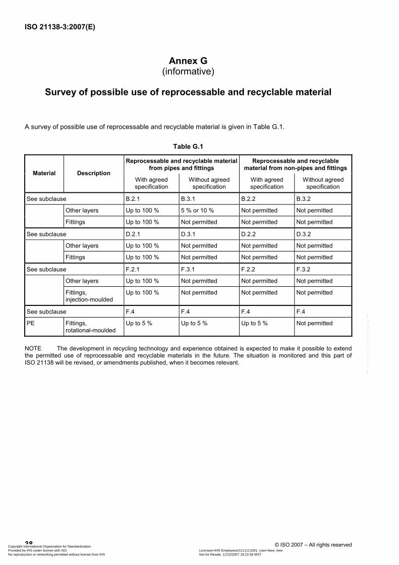
ISO 21138-3:2007(E)
38 © ISO 2007 – All rights reserved
Annex G (informative)
Survey of possible use of reprocessable and recyclable material
A survey of possible use of reprocessable and recyclable material is given in Table G.1.
Table G.1
Reprocessable and recyclable material from pipes and fittings
Reprocessable and recyclable material from non-pipes and fittings
Material Description With agreed specification
Without agreed specification
With agreed specification
Without agreed specification
See subclause B.2.1 B.3.1 B.2.2 B.3.2
Other layers Up to 100 % 5 % or 10 % Not permitted Not permitted
Fittings Up to 100 % Not permitted Not permitted Not permitted
See subclause D.2.1 D.3.1 D.2.2 D.3.2
Other layers Up to 100 % Not permitted Not permitted Not permitted
Fittings Up to 100 % Not permitted Not permitted Not permitted
See subclause F.2.1 F.3.1 F.2.2 F.3.2
Other layers Up to 100 % Not permitted Not permitted Not permitted
Fittings, injection-moulded
Up to 100 % Not permitted Not permitted Not permitted
See subclause F.4 F.4 F.4 F.4
PE Fittings, rotational-moulded
Up to 5 % Up to 5 % Up to 5 % Not permitted
NOTE The development in recycling technology and experience obtained is expected to make it possible to extend the permitted use of reprocessable and recyclable materials in the future. The situation is monitored and this part of ISO 21138 will be revised, or amendments published, when it becomes relevant.
Copyright International Organization for Standardization Provided by IHS under license with ISO Licensee=IHS Employees/1111111001, User=leee, leee
Not for Resale, 11/22/2007 19:22:36 MSTNo reproduction or networking permitted without license from IHS
--`,```,``,`,,`,`,`,,``,``,`,`,-`-`,,`,,`,`,,`---
ISO 21138-3:2007(E)
© ISO 2007 – All rights reserved 39
Bibliography
[1] ISO 161-1:1996, Thermoplastics pipes for the conveyance of fluids — Nominal outside diameters and nominal pressures — Part 1: Metric series
[2] ISO 9001, Quality management systems — Requirements
[3] ISO 9002:1994, Quality systems — Model for quality assurance in production, installation and servicing
Copyright International Organization for Standardization Provided by IHS under license with ISO Licensee=IHS Employees/1111111001, User=leee, leee
Not for Resale, 11/22/2007 19:22:36 MSTNo reproduction or networking permitted without license from IHS
--`,```,``,`,,`,`,`,,``,``,`,`,-`-`,,`,,`,`,,`---
ISO 21138-3:2007(E)
ICS 23.040.20; 23.040.45; 91.140.80; 93.030 Price based on 39 pages
© ISO 2007 – All rights reserved
Copyright International Organization for Standardization Provided by IHS under license with ISO Licensee=IHS Employees/1111111001, User=leee, leee
Not for Resale, 11/22/2007 19:22:36 MSTNo reproduction or networking permitted without license from IHS
--`,```,``,`,,`,`,`,,``,``,`,`,-`-`,,`,,`,`,,`---