INTERNATIONAL ISO STANDARD 15590-3 -...
24
Reference number ISO 15590-3:2004(E) © ISO 2004 INTERNATIONAL STANDARD ISO 15590-3 First edition 2004-11-01 Petroleum and natural gas industries — Induction bends, fittings and flanges for pipeline transportation systems — Part 3: Flanges Industries du pétrole et du gaz naturel — Coudes d'induction, raccords et brides pour systèmes de transport par conduites — Partie 3: Brides www.bzfxw.com ural gas indus l gas indu , fittings and fl ngs and fl portation syste tation syst es du pétrole et du gaz s du pétrole et du gaz des pour systèmes de t pour systèmes de artie 3: Brides : Brides o o o o o o om om om
Transcript of INTERNATIONAL ISO STANDARD 15590-3 -...

Reference number
ISO 15590-3:2004(E)
© ISO 2004
INTERNATIONAL STANDARD
ISO15590-3
First edition2004-11-01
Petroleum and natural gas industries — Induction bends, fittings and flanges for pipeline transportation systems —
Part 3: Flanges
Industries du pétrole et du gaz naturel — Coudes d'induction, raccords et brides pour systèmes de transport par conduites —
Partie 3: Brides
www.bzfx
w.com
ural gas indusl gas indu, fittings and flngs and fl
portation systetation syst
es du pétrole et du gaz s du pétrole et du gaz des pour systèmes de tpour systèmes de
artie 3: Brides : Brides
ooooooomomom
ISO 15590-3:2004(E)
PDF disclaimer
This PDF file may contain embedded typefaces. In accordance with Adobe's licensing policy, this file may be printed or viewed but
shall not be edited unless the typefaces which are embedded are licensed to and installed on the computer performing the editing. In
downloading this file, parties accept therein the responsibility of not infringing Adobe's licensing policy. The ISO Central Secretariat
accepts no liability in this area.
Adobe is a trademark of Adobe Systems Incorporated.
Details of the software products used to create this PDF file can be found in the General Info relative to the file; the PDF-creation
parameters were optimized for printing. Every care has been taken to ensure that the file is suitable for use by ISO member bodies. In the unlikely event that a problem relating to it is found, please inform the Central Secretariat at the address given below.
© ISO 2004
All rights reserved. Unless otherwise specified, no part of this publication may be reproduced or utilized in any form or by any means,
electronic or mechanical, including photocopying and microfilm, without permission in writing from either ISO at the address below or
ISO's member body in the country of the requester.
ISO copyright office
Case postale 56 CH-1211 Geneva 20
Tel. + 41 22 749 01 11
Fax + 41 22 749 09 47
E-mail [email protected]
Web www.iso.org
Published in Switzerland
ii © ISO 2004 – All rights reserved
www.bzfx
w.comm
ISO 15590-3:2004(E)
© ISO 2004 – All rights reserved iii
Contents Page
Foreword............................................................................................................................................................ iv
Introduction ........................................................................................................................................................ v
1 Scope...................................................................................................................................................... 1
2 Normative references ........................................................................................................................... 1
3 Terms and definitions........................................................................................................................... 3
4 Symbols and abbreviated terms.......................................................................................................... 4
5 Designation of flanges.......................................................................................................................... 4
6 Pressure class and design................................................................................................................... 5
7 Information to be supplied by the purchaser..................................................................................... 57.1 Principal information ............................................................................................................................ 57.2 Supplementary information ................................................................................................................. 6
8 Manufacturing ....................................................................................................................................... 68.1 Manufacturing procedure specification.............................................................................................. 68.2 Starting material.................................................................................................................................... 68.3 Hubs ....................................................................................................................................................... 68.4 Heat treatment ....................................................................................................................................... 7
9 Testing and inspection......................................................................................................................... 79.1 General requirements ........................................................................................................................... 79.2 Extent of testing and inspection ......................................................................................................... 79.3 Chemical composition.......................................................................................................................... 89.4 Physical testing..................................................................................................................................... 89.5 NDT....................................................................................................................................................... 129.6 Dimensions.......................................................................................................................................... 139.7 Hydrostatic testing.............................................................................................................................. 149.8 Weldability ........................................................................................................................................... 149.9 Repair welding..................................................................................................................................... 15
10 Documentation .................................................................................................................................... 1510.1 Inspection document .......................................................................................................................... 1510.2 Manufacturing record book ............................................................................................................... 15
11 Marking ................................................................................................................................................ 15
Bibliography ..................................................................................................................................................... 17
www.bzfx
w.com
.........
...................................
................................... ................
........................................................
.............................................................
............................................................
...............................................................
......................................................................................................................
.....................................................
...................................................................................................................
................................................................................................................................
..................................................................
..........................................................................................................................
pection ........................n .......................................................................................
.....................................................................................................................................
.....................................................esting..........................g..........................
y .........................................................welding.........................g........................
umentation .................ation ...............spection document ...n documen
Manufacturing recordufacturing recor
wwMarking ...............Marking ...........
Bibliography .............raphy ..........
ISO 15590-3:2004(E)
iv © ISO 2004 – All rights reserved
Foreword
ISO (the International Organization for Standardization) is a worldwide federation of national standards bodies (ISO member bodies). The work of preparing International Standards is normally carried out through ISO technical committees. Each member body interested in a subject for which a technical committee has been established has the right to be represented on that committee. International organizations, governmental and non-governmental, in liaison with ISO, also take part in the work. ISO collaborates closely with the International Electrotechnical Commission (IEC) on all matters of electrotechnical standardization.
International Standards are drafted in accordance with the rules given in the ISO/IEC Directives, Part 2.
The main task of technical committees is to prepare International Standards. Draft International Standards adopted by the technical committees are circulated to the member bodies for voting. Publication as an International Standard requires approval by at least 75 % of the member bodies casting a vote.
Attention is drawn to the possibility that some of the elements of this document may be the subject of patent rights. ISO shall not be held responsible for identifying any or all such patent rights.
ISO 15590-3 was prepared by Technical Committee ISO/TC 67, Materials, equipment and offshore structures for petroleum, petrochemical and natural gas industries, Subcommittee SC 2, Pipeline transportation systems.
ISO 15590 consists of the following parts, under the general title Petroleum and natural gas industries — Induction bends, fittings and flanges for pipeline transportation systems:
— Part 1: Induction bends
— Part 2: Fittings
— Part 3: Flanges
www.bzfx
w.comug
e has bernmental anntal an
closely with the y with the zation.
Directives, Part 2. ves, Part 2
Draft International Stanernational Stas for voting. Publicatiovoting. Publicat
dies casting a vote. asting a vote.
document may be the ay be thech patent rights. nt r
7, Materials, equipmenrials, equipmenbcommittee SC 2, mittee SC 2, PipelPipe
general title general title Petroleuoleunsportation systemsortation systems::
ISO 15590-3:2004(E)
© ISO 2004 – All rights reserved v
Introduction
Users of this part of ISO 15590 should be aware that further or differing requirements may be needed for individual applications. This part of ISO 15590 is not intended to inhibit a manufacturer from offering, or the purchaser from accepting, alternative equipment or engineering solutions for the individual application. This can be particularly applicable where there is innovative or developing technology. Where an alternative is offered, the manufacturer should identify any variations from this part of ISO 15590 and provide details.
mal appl
here an altean alte
www.bzfx
w.com
d provide details.ide details.

www.bzfx
w.com
INTERNATIONAL STANDARD ISO 15590-3:2004(E)
© ISO 2004 – All rights reserved 1
Petroleum and natural gas industries — Induction bends, fittings and flanges for pipeline transportation systems —
Part 3: Flanges
1 Scope
This part of ISO 15590 applies to weldneck and blind flanges (full face, raised face, and RTJ groove) as well as anchor, swivel-ring flanges and orifice flanges.
This part of ISO 15590 specifies the technical requirements for carbon steel and low-alloy steel forged flanges for use in pipeline transportation systems for the petroleum and natural gas industries as defined in ISO 13623.
This part of ISO 15590 designates those categories of flanges that meet the industry's need to match ISO 3183 pipe. These flanges are for normal and low-temperature service and include supplementary requirements where required for sour service.
Materials for, or the attachment of, factory-welded extensions, bolting materials, gaskets, slip-on flanges or flanged fittings are not covered by this part of ISO 15590.
This part of ISO 15590 is not applicable to integrally cast or forged flanges for valves, pumps or other equipment.
This part of ISO 15590 does not cover the selection of the flange category or pressure class. Sizes and pressure classes listed in ISO 7005-1 and applicable to this part of ISO 15590 are as follows:
DN 10 (NPS 1/2) to DN 1500 (NPS 60);
PN 20 (class 150), PN 50 (class 300), PN 100 (class 600), PN 150 (class 900), PN 250 (class 1500), PN 420 (class 2500).
2 Normative references
The following referenced documents are indispensable for the application of this document. For dated references, only the edition cited applies. For undated references, the latest edition of the referenced document (including any amendments) applies.
ISO 148-1, Metallic material —- Charpy pendulum impact test — Part 1: Test method
ISO 377, Steel and steel products — Location and preparation of samples and test pieces for mechanical testing
ISO 783, Metallic materials — Tensile testing at elevated temperature
ISO 2566-1, Steel — Conversion of elongation values — Part 1: Carbon and low alloy steels
www.bzfx
w.com
face, raised face, and aised face, and
for carbon steel and lobon steel aetroleum and natural m and natural
egories of flanges thatof flanges thmal and low-temperatual and low-temperat
e.
actory-welded extensionwelded extensiohis part of ISO 15590. rt of ISO 15590.
ot applicable to integrat applicable to integr
90 does not cover the es not cover the ted in ISO 7005-1 and aO 7005-1 and
PS 1/2) to DN 1500 (NP2) to DN 1500
20 (class 150), PN 50 ass 150), PN 50N 420 (class 2500). class 2500
2 Normative reNormative re
wThe following The following eferences, erenceswumentent
ISO 15590-3:2004(E)
2 © ISO 2004 – All rights reserved
ISO 3183-1, Petroleum and natural gas industries — Steel pipe for pipelines — Technical delivery conditions — Part 1: Pipes of requirement class A
ISO 3183-2, Petroleum and natural gas industries — Steel pipe for pipelines — Technical delivery conditions — Part 2: Pipes of requirement class B
ISO 3183-3, Petroleum and natural gas industries — Steel pipe for pipelines — Technical delivery conditions — Part 3: Pipes of requirement class C
ISO 4885, Ferrous products — Heat treatments — Vocabulary
ISO 6507-1:1997, Metallic materials — Vickers hardness test — Part 1: Test method
ISO 6892, Metallic materials — Tensile testing at ambient temperature
ISO 7005-1:1992, Metallic flanges — Part 1: Steel flanges
ISO/TR 7705:1991, Guidelines for specifying Charpy V-notch impact prescriptions in steel specifications
ISO 9327-1, Steel forgings and rolled or forged bars for pressure purposes — Technical delivery conditions — Part 1: General requirements
ISO 9712, Non-destructive testing — Qualification and certification of personnel
ISO 10474:1991, Steel and steel products — Inspection documents
ISO 11496, Seamless and welded steel tubes for pressure purposes — Ultrasonic testing of tube ends for the detection of laminar imperfections
ISO 12095, Seamless and welded steel tubes for pressure purposes — Liquid penetrant testing
ISO 13623, Petroleum and natural gas industries — Pipeline transportation systems
ISO 13664, Seamless and welded steel tubes for pressure purposes — Magnetic particle inspection of the tube ends for the detection of laminar imperfections
ISO 13665, Seamless and welded steel tubes for pressure purposes — Magnetic particle inspection of the tube body for the detection of surface imperfections
ISO 15156-2:2003, Petroleum and natural gas industries — Materials for use in H2S-containing environments in oil and gas production — Part 2: Cracking-resistant carbon and low alloy steels, and the use of cast irons
ISO 15590-1:2001, Petroleum and natural gas industries — Induction bends, fittings and flanges for pipeline transportation systems — Part 1: Induction bends
ISO 15590-2, Petroleum and natural gas industries — Induction bends, fittings and flanges for pipeline transportation systems — Part 2: Fittings
ASME Boiler and Pressure Vessel Code; Section VIII Division 1, Rules for Construction of Pressure Vessels
ASME B16.5, Pipe Flanges and Flanged Fittings — NPS 1/2 through 24
ASME B16.361), Orifice Flanges
ASME B16.47, Large Diameter Steel Flange —– NPS 26 through NPS 60
ASME B31.3, Process piping
ASTM A 370-03a1), Standard Test Methods and Definitions for Mechanical Testing of Steel Products
ASTM E 112-96e3, Standard Test Methods for Determining Average Grain Size
1) American Society for Testing and Materials, 100 Bar Harbor Drive, West Conshohocken, PA 19428-2959, USA
ww.bzfx
w.comin steel specificationsl specifications
— Technical delivery conhnical delivery co
personnel
ts
urposes — Ultrasonic tes — Ultrasoni
ssure purposes — Liquisure purposes — Liqu
— Pipeline transportatpeline transpo
bes for pressure purpor pressure purpoerfectionsns
teel tubes for pressureel tubes for pressurace imperfectionsperfections
m and natural gas indusnatural gas indus— Part 2: Cracking-resis2: Cracking-resis
etroleum and natural gaum and naturaems — Part 1: InductionPart 1: Induction
wwwPetroleum and naturaeum and naturaon systems — Part 2: Ftems — Part 2
Boiler and Pressure Vesnd Pressure V
ME B16.5, 5, Pipe FlangePipe Fla
B16.3616.361)1),, OrifiO
7, L
ISO 15590-3:2004(E)
© ISO 2004 – All rights reserved 3
MSS SP 442), 1996 Steel Pipeline Flanges
3 Terms and definitions
For the purposes of this document, the terms and definitions given in ISO 4885 and the following apply.
3.1ANSI rating classnumerical pressure design class defined in ASME B16.5 and used for reference purposes
NOTE The ANSI rating class is designated by the word “Class” followed by a number.
[ISO 14313:1999][1]
3.2by agreement agreed between manufacturer and purchaser
[ISO 14313:1999][1]
3.3heat batch of steel prepared in one steel-making operation
[ISO 15590-1:2001]
3.4imperfection irregularity in the wall or on the surface detectable by methods described in this part of ISO 15590
3.5manufacturing procedure specification MPS document which specifies the process control parameters and the acceptance criteria to be applied for all manufacturing, inspection and testing activities performed during flange manufacture
NOTE Adapted from ISO 15590-2.
3.6matching pipe specified pipe grade and thickness to which the flange will be attached
3.7pressure class numerical pressure design class expressed in accordance with either the nominal pressure (PN) class or the ANSI rating class
NOTE In this part of ISO 15590, the pressure class is stated by the PN class followed by the ANSI rating class between brackets.
[ISO 14313:1999][1]
2) Manufacturer’s Standardization Society of the Valve and Fittings Industry, 127 Park Street, N.E., Vienna, Virginia 22180, USA
ce detectable by methodectable by metho
pecification ecification
es the process controess controction and testing activitind testing activiti
ed from ISO 15590-2. ISO 15590
g pipe e
wwied pipe grade and thicgrade an
.7pressure class ssure clanumerical pressurmerical prewANSI rating clasANSI rating cla
TE en
ISO 15590-3:2004(E)
4 © ISO 2004 – All rights reserved
4 Symbols and abbreviated terms
Ao original cross-sectional area of the parallel length of a test specimen
CE carbon equivalent
DN nominal diameter
HIC hydrogen-induced cracking
HV Vickers hardness
ID inside diameter
L low-temperature service
LS low-temperature sour service
MPS manufacturing procedure specification
MT magnetic particle testing
N normal service
NDT non-destructive testing
NPS nominal pipe size
NS normal sour service
PN nominal pressure
PT liquid penetrant testing
Rm tensile strength
RTJ ring type joint
S sour service
SMTS specified minimum tensile strength
SMYS specified minimum yield strength
SSC sulfide stress cracking
t specified wall thickness at the welding ends for flanges
Td min minimum design temperature
UT ultrasonic testing
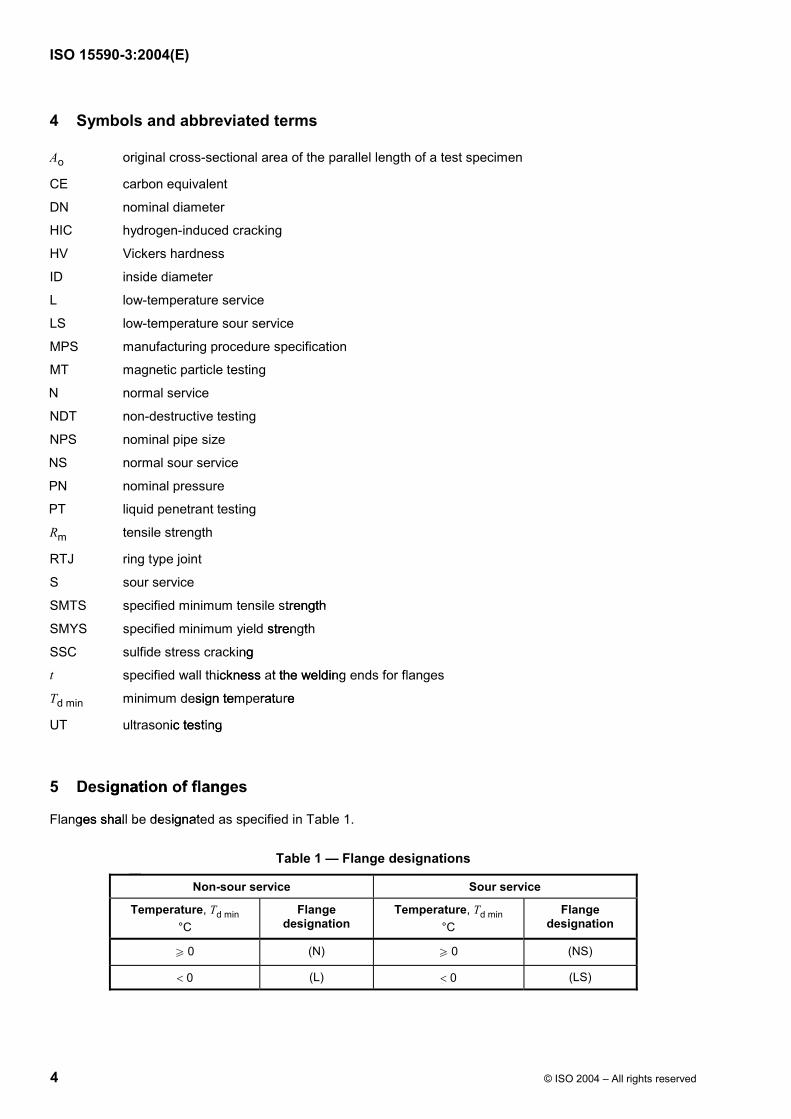
5 Designation of flanges
Flanges shall be designated as specified in Table 1.
Table 1 — Flange designations
Non-sour service Sour service
Temperature, Td min
°C
Flangedesignation
Temperature, Td min
°C
Flangedesignation
W 0 (N) W 0 (NS)
0 (L) 0 (LS)
strength strength
d strength ength
ing
hickness at the weldings at the welding
esign temperature mperature
nic testing ting
signation of flangetion of flange
wges shall be designateall be desigw

ISO 15590-3:2004(E)
© ISO 2004 – All rights reserved 5
Flanges with a minimum design temperature lower than 0 °C shall demonstrate proven notch toughness in accordance with Clause 9.
Flanges intended for sour service shall be so specified by the purchaser and meet the applicable requirements of Clause 9.
6 Pressure class and design
The flange shall be capable of withstanding an internal pressure equal to the working pressure at the temperature range required. Maximum pressures for the various pressure classes against temperature are shown in Table 2.
Table 2 — Maximum pressures as a function of temperature
PN
20 50 100 150 250 420
Class
150 300 600 900 1500 2500
Temperature
°C
MPa (bar) MPa (bar) MPa (bar) MPa (bar) MPa (bar) MPa (bar)
30 to 120 1,96 (19,6) 5,11 (51,1) 10,2 (102) 15,3 (153) 25,5 (255) 42,6 (426)
150 1,9 (19) 4,93 (49,3) 9,86 (98,6) 14,8 (148) 22,6 (226) 37,7 (377)
175 1,83 (18,3) 4,75 (47,5) 9,51 (95,1) 14,3 (143) 22,2 (222) 34,1 (341)
200 1,76 (17,6) 4,59 (45,9) 9,17 (91,7) 13,8 (138) 21,9 (219) 36,5 (365)
250 1,7 (17) 4,41 (44,1) 8,86 (88,6) 13,3 (133) 22,5 (225) 35,5 (355)
For any temperature below 30 °C, the rating shall be no greater than the rating shown for 30 °C.
For intermediate temperatures, linear interpolation should be used.
Ratings of flanges for temperatures greater than those given shall be by agreement.
If there are any deviations from the flange dimensions specified in ISO 7005-1, pressure-containment calculations shall be made in accordance with an agreed pressure-vessel design standard such as ASME Section VIII, Division 1.
The design calculations shall be available for review.
For pipeline applications, the design criteria shall be in accordance with ISO 7005-1:1992, Annex F.
NOTE External loads or moments are not covered by this part of ISO 15590. However, swivels and anchor flanges
can experience external loads and can be designed using the equivalent pressure method.
7 Information to be supplied by the purchaser
7.1 Principal information
The following information shall be provided:
a) flange designation, size and class;
b) quantity of flanges;
zfxw.co
ming pressress
gainst temperatempera
perature ure
om150 250 250 ccccocs
900 900 ccccw
c(bar) MPa (bar) MPa (bar)
wwc
wwc
(102) 15,3 (1502) 15,3 (wwwwwwwxxww9,86 (98,6) 14,8 (98,6) 14,8xxxwxwxwwwfxxww) 9,51 (95,1) 149,51 (95,1) fxfxfxwxwxwffxxw45,9) 9,17 (91,7) 9,17 (91,fffxfxfxbz
fxxxzffxx (44,1) 8,86 (88,4,1) 8,86 (88zfzfzfxfxfxbbzffx
e rating shall be no greathall be no grea
inear interpolation shouldear interpolation should
www.beratures greater than thosreater than thbbbzf
bzf
bzfff
bny deviations from thations from th
shall be made in accobe made in accII, Division 1. ion 1.
design calculations shalculations
For pipeline applicationeline applicat
NOTE ExternaNOTE Exte
can experience ecan experience
ISO 15590-3:2004(E)
6 © ISO 2004 – All rights reserved
c) material grade;
d) wall thickness, specified minimum yield strength and bore size for the matching pipe;
e) flange facing (e.g. raised face, RTJ).
7.2 Supplementary information
If applicable, the following supplementary information shall be provided:
a) minimum and maximum design temperatures;
b) special dimensional requirements;
c) requirements for supplementary inspection and testing;
d) pipeline-design standard or design factors, if different from ISO 13623 (e.g. anchor and swivel flanges);
e) pipeline operating conditions;
f) mechanical property requirements at the maximum design temperature;
g) hold-points for witness and approval;
h) marking requirements if different from this part of ISO 15590;
i) packaging and shipping instructions;
j) third-party inspection organization.
8 Manufacturing
8.1 Manufacturing procedure specification
Flanges shall be manufactured in accordance with a documented MPS, which includes all of the necessary steps to be taken in the manufacture of flanges to this part of ISO 15590. The MPS shall address the information listed in Clause 7 as applicable. Additional details may be required in the MPS prior to the commencement of manufacturing.
8.2 Starting material
Forgings shall meet the requirements of ISO 9327-1. The starting material for forged flanges shall be ingot, bloom, billet, slab, plate (for blind flanges only) or bar and shall be fully killed steel (see ISO 7005-1:1992, Table D.3). Flanges shall not be machined from bars.
The material designation shall be consistent with ISO 3183-1, ISO 3183-2 and ISO 3183-3.
8.3 Hubs
Pipeline applications shall be in accordance with ISO 7005-1:1992, 2.4.5. Hubs shall be single slope or dual slope in accordance with ISO 7005-1.
www.bzfx
w.com
anchor and swivel flanor and swivel fla
erature; e;
15590; ;
dure specification fication
tured in accordance win accordance he manufacture of flanufacture of fla
Clause 7 as applicablse 7 as applica
wwmanufacturing. acturing.
ng material aterial
gs shall meet the requimeet the reqm, billet, slab, plate (foet, slab, plate (fo
we D.3). Flanges shall.3). Flanges sh
rial designal desig
ISO 15590-3:2004(E)
© ISO 2004 – All rights reserved 7
8.4 Heat treatment
Heat-treatment vocabulary shall be in accordance with ISO 4885.
Forged flanges shall be normalized, normalized and tempered, or quenched and tempered after forming. The heat treatment shall be performed in accordance with a documented procedure. A record (heat treat chart) shall be maintained of each heat treatment and shall be included in the inspection document, if specified.
The tolerances on soaking temperature shall be 15 °C and on soaking time 20 %.
9 Testing and inspection
9.1 General requirements
Testing and inspection shall be carried out on flange forgings after final heat treatment. If the pipeline installation techniques will require post-weld heat treatment of the flange, additional testing can be required to demonstrate that the mechanical properties of the flange are achieved after post-weld heat treatment. Details of the post-weld heat treatment cycle to be used during pipeline installation shall be specified. The test requirements and acceptance criteria shall be by agreement.
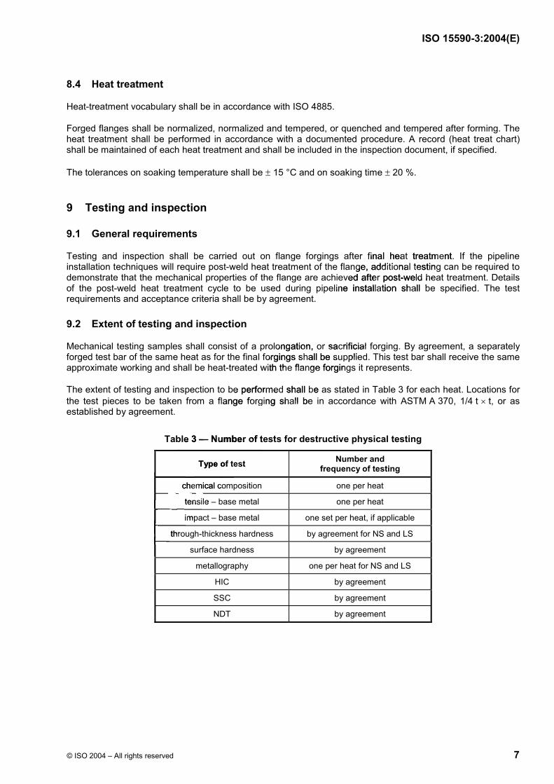
9.2 Extent of testing and inspection
Mechanical testing samples shall consist of a prolongation, or sacrificial forging. By agreement, a separately forged test bar of the same heat as for the final forgings shall be supplied. This test bar shall receive the same approximate working and shall be heat-treated with the flange forgings it represents.
The extent of testing and inspection to be performed shall be as stated in Table 3 for each heat. Locations for
the test pieces to be taken from a flange forging shall be in accordance with ASTM A 370, 1/4 t t, or as established by agreement.
Table 3 — Number of tests for destructive physical testing
Type of test Number and
frequency of testing
chemical composition one per heat
tensile – base metal one per heat
impact – base metal one set per heat, if applicable
through-thickness hardness by agreement for NS and LS
surface hardness by agreement
metallography one per heat for NS and LS
HIC by agreement
SSC by agreement
NDT by agreement
final heat treatment. at treatmege, additional testing cdditional testing
ved after post-weld heaer post-weld healine installation shall bllation sha
ongation, or sacrificial ion, or sacrificial forgings shall be supplieforgings shall be supp
d with the flange forgingwith the flange for
be performed shall be aformed shall be
lange forging shall be forging shall be
le 3 — Number of test— Number of test
Type of test of test bwchemical comchemical comww.wtensile –tensilewwwwimpim
wwwwwwthrwwwwwwwww
ISO 15590-3:2004(E)
8 © ISO 2004 – All rights reserved
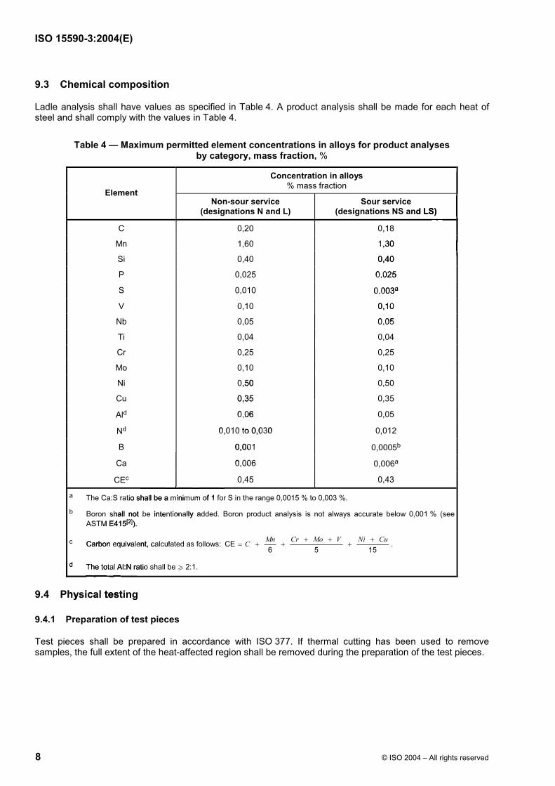
9.3 Chemical composition
Ladle analysis shall have values as specified in Table 4. A product analysis shall be made for each heat of steel and shall comply with the values in Table 4.
Table 4 — Maximum permitted element concentrations in alloys for product analyses by category, mass fraction, %
Concentration in alloys
% mass fractionElement
Non-sour service (designations N and L)
Sour service (designations NS and LS)
C 0,20 0,18
Mn 1,60 1,30
Si 0,40 0,40
P 0,025 0,025
S 0,010 0,003a
V 0,10 0,10
Nb 0,05 0,05
Ti 0,04 0,04
Cr 0,25 0,25
Mo 0,10 0,10
Ni 0,50 0,50
Cu 0,35 0,35
Ald 0,06 0,05
Nd 0,010 to 0,030 0,012
B 0,001 0,0005b
Ca 0,006 0,006a
CEc 0,45 0,43
a The Ca:S ratio shall be a minimum of 1 for S in the range 0,0015 % to 0,003 %.
b Boron shall not be intentionally added. Boron product analysis is not always accurate below 0,001 % (see
ASTM E415[2]).
c Carbon equivalent, calculated as follows: CE6 5 15
Mn Cr Mo V Ni CuC .
d The total Al:N ratio shall be W 2:1.
9.4 Physical testing
9.4.1 Preparation of test pieces
Test pieces shall be prepared in accordance with ISO 377. If thermal cutting has been used to remove samples, the full extent of the heat-affected region shall be removed during the preparation of the test pieces.
ww.bzfx
w.commnd LS) mmmmmm1,30 m
0,40 m
0,025 0,025
0,0030,00 a
0,10 0,10
w0,05 0,0
w0wxwxw0,50 x0,35 5 x0,06 0,06
0,010 to 0,030 0,010 to 0,030
0,001 0,001
0,0060,006
wwtio shall be a minimum of 1 fl be a minimum of
shall not be intentionally adbe intentionall
wwM E415[2]). )
Carbon equivalent, calculaon equivalent, calcu
d The total Al:N ratio The total Al:N ratio
www.
wwwwwhysical testhysical test
ra
ISO 15590-3:2004(E)
© ISO 2004 – All rights reserved 9
9.4.2 Tensile testing
9.4.2.1 Test pieces
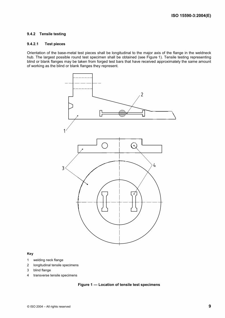
Orientation of the base-metal test pieces shall be longitudinal to the major axis of the flange in the weldneck hub. The largest possible round test specimen shall be obtained (see Figure 1). Tensile testing representing blind or blank flanges may be taken from forged test bars that have received approximately the same amount of working as the blind or blank flanges they represent.
Key
1 welding neck flange
2 longitudinal tensile specimens
3 blind flange
4 transverse tensile specimens
Figure 1 — Location of tensile test specimens
www.bzfx
w.com
ffxxw
ww.bzfxfx
w.co
bbbbbbbbbbbbbxwxwxwxwxwxwxwxwxwxwxwxwxw
ISO 15590-3:2004(E)
10 © ISO 2004 – All rights reserved
9.4.2.2 Test method
Tensile testing at ambient temperature shall be carried out in accordance with ISO 6892. If specified, tensile testing at elevated temperatures shall be carried out in accordance with ISO 783.
The frequency of all testing shall meet the requirements of Table 3.
For tensile tests, percentage elongation after fracture shall be determined. The percentage elongation after
fracture shall be reported with reference to a gauge length of 05,65 A . If other gauge lengths are used, the
elongation referred to a gauge length of 05,65 A shall be determined in accordance with ISO 2566-1.
9.4.2.3 Requirements
The material used shall meet the requirements of Table 6. The allowance for pipeline applications listed in ISO 7005-1:1992, 2.4.5, can be used.
9.4.3 Charpy V-notch impact tests
9.4.3.1 Test pieces
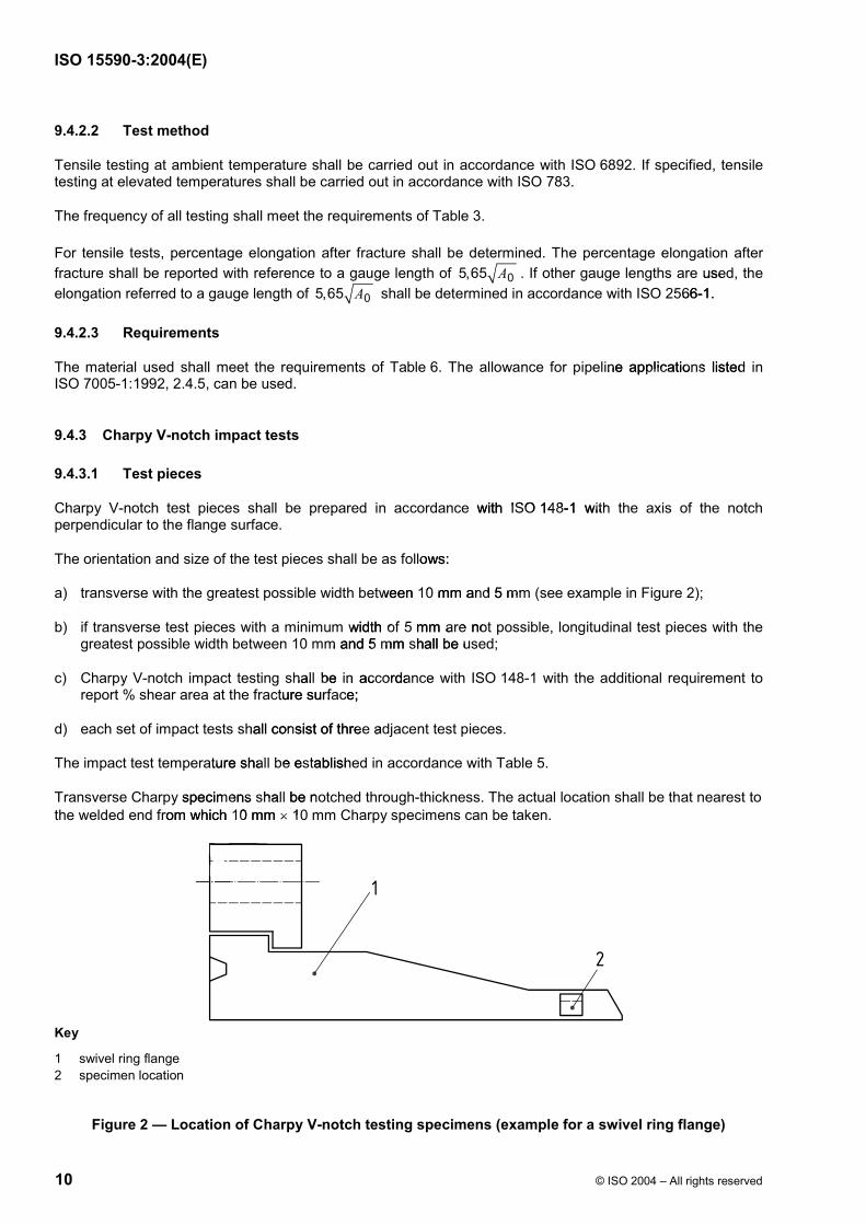
Charpy V-notch test pieces shall be prepared in accordance with ISO 148-1 with the axis of the notch perpendicular to the flange surface.
The orientation and size of the test pieces shall be as follows:
a) transverse with the greatest possible width between 10 mm and 5 mm (see example in Figure 2);
b) if transverse test pieces with a minimum width of 5 mm are not possible, longitudinal test pieces with the greatest possible width between 10 mm and 5 mm shall be used;
c) Charpy V-notch impact testing shall be in accordance with ISO 148-1 with the additional requirement to report % shear area at the fracture surface;
d) each set of impact tests shall consist of three adjacent test pieces.
The impact test temperature shall be established in accordance with Table 5.
Transverse Charpy specimens shall be notched through-thickness. The actual location shall be that nearest to
the welded end from which 10 mm 10 mm Charpy specimens can be taken.
Key
1 swivel ring flange
2 specimen location
Figure 2 — Location of Charpy V-notch testing specimens (example for a swivel ring flange)
www.bzfx
w.com
use
66-1.
ine applications listed pplications listed
e with ISO 148-1 withISO 148-1 with
llows: llo
ween 10 mm and 5 mmn 10 mm and 5 mm
width of 5 mm are notof 5 mm are notm and 5 mm shall be us5 mm shall be u
hall be in accordance all be in accordance cture surface; urface
shall consist of three adonsist of three ad
ature shall be establisheall be establish
y specimens shall be nomens shall be n
from which 10 mm which 10 mm 10 1
wwwwww
ISO 15590-3:2004(E)
© ISO 2004 – All rights reserved 11
Table 5 — Maximum Charpy V-notch test temperature by category
Nominal wall thickness, tmm
Td min for N and NS
°C
Td min for L and LS
°C
u 20 u 0 u 10
20, u 25 u 0 u 20
25 u 0 by agreement
9.4.3.2 Requirements
Charpy V-notch tests shall be carried out in accordance with ISO 148-1.
The minimum average absorbed energy, in joules, of the Charpy V-notch impact tests in the transverse direction shall meet the requirements in Table 6.
Table 6 — Mechanical properties by steel grade
Steel grade SMYS
N/mm2
SMTS
N/mm2
Elongation
%
Minimum average Charpy V-notch value
J
Minimum Charpy V-notch value
J
245 415 22 27 22
290 415 21 30 24
360 460 20 36 30
415 520 18 42 35
450 535 18 45 38
485 570 18 50 40
555 625 18 56 45
The tensile requirements for intermediate grades shall be obtained by interpolation between those specified for
standard grades.
The minimum average and individual Charpy V-notch values when testing test pieces taken in the longitudinal direction shall be at least 1,5 times the values stated for transverse test pieces.
If specified, the minimum average shear area shall be 50 % of the fracture surface for any set of tests and all individual test pieces shall exhibit at least 40 % fibrous shear.
For subsidiary test pieces, the minimum required absorbed energy values shall be adjusted in accordance with ISO TR 7705:1991, Clause 6.
9.4.4 Hardness requirements
Through-thickness hardness testing shall be performed using the Vickers method in accordance with ISO 6507-1:1997, method HV10 (i.e. with a test force of 98,07 N).
Hardness indent locations for flanges shall be by agreement.
No hardness reading shall exceed 250 HV10 for sour-service flange forgings and 300 HV10 for non-sour service-flange forgings.
w.bzfx
w.comch impact tests in the pact tests in th
y steel gradegr
Minimum average m average Charpy V-notch value V-notch value
JJ
MMccccc2 27 27 wx21 321 3xxxwfx20 20 fxfxfxwfx18 18 fxfxfxzfx5 18 18 zzzfffbzf
570 18 570 18
bzbzbzbz625 1625 1bzbzbzbzrements for intermediate gramediate gr
s. bbbw
wwwaverage and individual and individall be at least 1,5 times at least 1,5 times
fied, the minimum averhe minimum aveidual test pieces shall etest pieces sha
For subsidiary test piesidiary test with ISO TR 7705:1 ISO TR 7705:1
9.4.4 Hardn9.4.4 Ha
ugh

ISO 15590-3:2004(E)
12 © ISO 2004 – All rights reserved
9.4.5 Metallographic examination
9.4.5.1 Method
Grain-size shall be determined in accordance with ASTM E 112.
9.4.5.2 Requirements
The photomicrographs shall demonstrate that the manufacturing process and any subsequent heat treatment have produced a consistent microstructure without separations in the base metal.
Forged flanges shall have an average grain-size number of 7 or finer.
9.4.6 HIC tests
If HIC testing is specified, the test procedures and acceptance criteria shall be in accordance with ISO 15156-2.
NOTE This test is not normally specified.
9.4.7 SSC tests
If SSC testing is specified, test procedures and acceptance criteria shall be in accordance with ISO 15156-2.
9.5 NDT
9.5.1 NDT personnel and procedures
NDT shall always be performed after final heat treatment.
All NDT shall be conducted in accordance with documented procedures.
If specified, NDT procedures shall be decided by agreement before commencement of flange manufacture.
All NDT personnel shall be qualified and certified in accordance with ISO 9712 to the appropriate level of competence. The minimum level of competence for UT shall be NDT level 2.
NOTE The pressure-vessel or similar industry would be an acceptable sector for the specific examination of
ISO 9712.
9.5.2 Forging preparation
All NDT for acceptance of forgings in accordance with the requirements of this part of ISO 15590 shall be performed after final heat treatment of forgings, except that the surfaces of forgings shall be finished so that surface imperfections can be detected by visual inspection.
The surface to be examined and all adjacent areas within 25 mm shall be dry and free from all dirt, grease, lint, scale, welding flux and spatter, oil or other extraneous matter that could interfere with the non-destructive examination.
9.5.3 Visual inspection
Forged flanges shall be free from dents with sharp bottom gouges or dents exceeding 3 mm in depth.
The depth of a gouge or dent shall be measured as the maximum distance between the contour of the gouge or dent and the normal flange contour.
www.bzfx
w.com
t treat
shall be in accordancin accordanc
riteria shall be in accordshall be in acc
eat treatment. atment
nce with documented pnce with documented p
l be decided by agreemded by agre
qualified and certifieded and certifiedm level of competence el of competence
sure-vessel or similar inessel or similar in
ging preparation reparation
T for acceptance of foacceptance of ormed after final heat tafter final ce imperfections cae imperfections
ce to be to beeldin
ISO 15590-3:2004(E)
© ISO 2004 – All rights reserved 13
9.5.4 MT/PT inspection
9.5.4.1 Method
The weld-end of flanges shall be inspected by MT in accordance with ISO 13664 for the presence of laminar imperfections. By agreement, PT or UT inspection may be carried out instead of MT. In case of UT inspection, the probe shall be placed on the inner surface of the flange.
All other areas of the flange shall be MT-inspected after all heat treatment has been completed. Each flange shall be inspected by magnetic particle testing in accordance with ISO 13665 or by liquid penetrant testing in accordance with ISO 12095.
9.5.4.2 Requirements
A percentage test shall be by agreement, provided a minimum of 10 % of the batch is tested.
Laminar or linear imperfections equal to or greater than 2 mm in the circumferential direction and with an area
exceeding 100 mm2 shall not be permitted.
If any unacceptable imperfection is found on the test sample, then 100 % testing shall be carried out on the lot.
Imperfections not classified as defects are permitted to remain in the flange without repair. Localized grinding, however, is permitted.
All dressable surface defects shall be dressed out by grinding. Grinding shall be carried out in such a way that the dressed area blends in smoothly with the contour of the flange. Complete removal of defects shall be verified by local visual inspection aided, if necessary, by suitable NDT methods.
9.5.5 UT inspection
9.5.5.1 Method
The final 50 mm of each end of the flange shall be UT-inspected for the detection of laminar imperfections in accordance with ISO 11496. Ultrasonic inspection for the detection of longitudinal and/or transverse imperfections shall be performed after all heat treatment has been completed.
The reference standard shall contain notches for longitudinal imperfections and radially drilled holes for transverse imperfections.
For the purpose of determining the extent of suspect areas, adjacent suspect areas separated by less than twice the minor axis of the imperfection shall be considered as a single imperfection.
9.5.5.2 Requirements
The frequency of testing shall be established by agreement.
Laminar imperfections equal to or greater than 6 mm in the circumferential direction and with an area
exceeding 100 mm2 shall not be permitted.
9.6 Dimensions
9.6.1 Flange dimensions
Dimensions of weldneck flanges shall be in accordance with ISO 7005-1 and shall be compatible with ASME B16.5, B16.36, B16.47 and MSS SP 44.
ww.bzfx
w.com
etedpenetrant a
e batch is tested. h is tested.
rcumferential direction aerential direction
then 100 % testing shtesting sh
remain in the flange win the flange w
out by grinding. Grindinout by grinding. Grindinthe contour of the flancontour of the fla
necessary, by suitable sary, by suitable
h end of the flange shaflange shO 11496. Ultrasonic in96. Ultrasonic in
be performed after all hrmed after all
e standard shall contandard shall conimperfections. ections.
e purpose of determinose of dete
wwce the minor axis of theminor axis of th
9.5.5.2 Requirem5.2 Requirem
The frequency The frequency
inar
ISO 15590-3:2004(E)
14 © ISO 2004 – All rights reserved
Dimensions of orifice flanges shall be in accordance with ASME B16.36.
Anchor flanges shall be designed in accordance with ISO 13623 or ASME B31.3.
Swivel-ring flanges shall be designed and calculations shall be made in accordance with an agreed pressure vessel design standard such as ASME Section VIII, Division 1. Swivel-ring flanges shall be suitable to bolt to existing ISO 7005-1 flanges and shall be compatible with ASME B16.5, B16.36, B16.47 and MSS SP 44. Swivel-ring flanges should have RTJ-groove-sealing faces.
9.6.2 Tolerances
Tolerances shall be in accordance with ISO 7005-1.
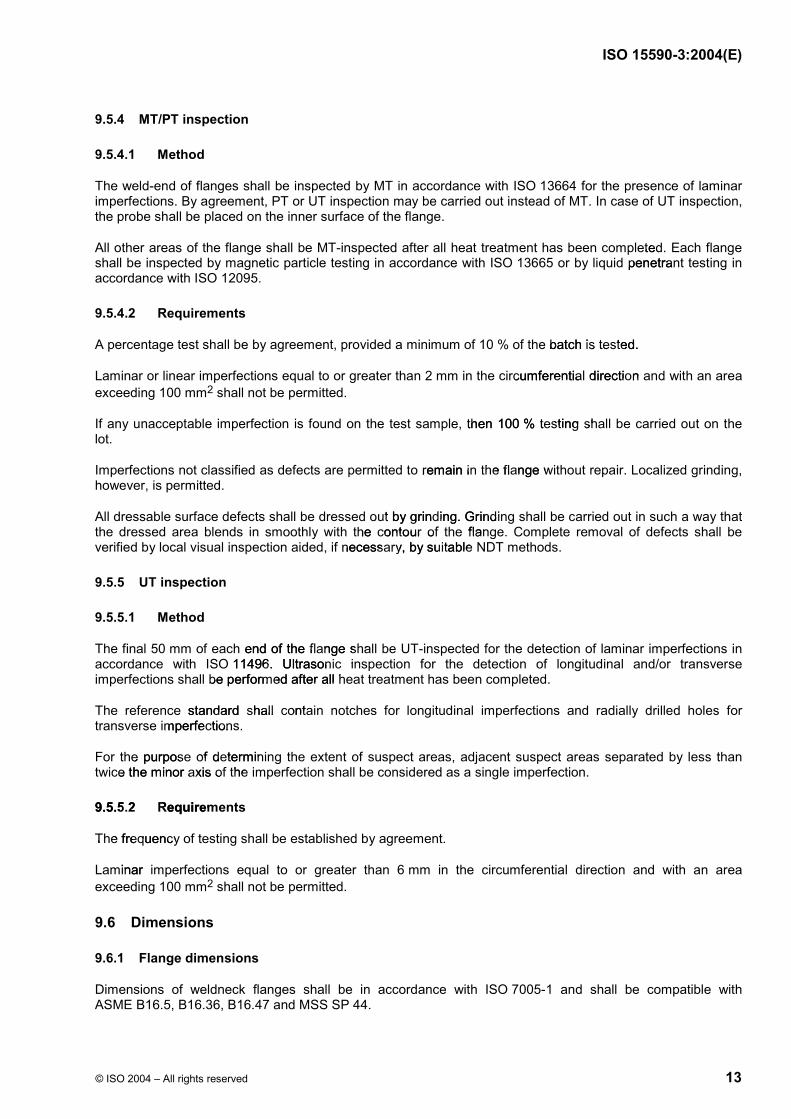
9.6.3 Flange-face finish
Flange-face finish shall be in accordance with ISO 7005-1 and Table 7.
Table 7 — Permissible imperfections in raised face flange finish
Pipe size
DN
mm
NPS
in
Maximum radial projection of imperfections which are no deeper
than the bottom of the serrationsa
mm
Maximum depth and radial projectionb
of imperfections which are deeper than the bottom of the serrations
mm
15 to 80 (1/2 to 3) 3 1,5
100 to 150 (4 to 6) 6 3
200 to 350 (8 to 14) 8 4
400 (16) 10 5
450 to 900 (18 to 36) 12 6
950 to 1 200 (38 to 48) 13 6,5
1 250 to 1 500 (50 to 60) 16 8
a Imperfections less than half the depth of the serrations shall not be cause for rejection.
b A radial projection shall be measured by the difference between an inner and an outer radius encompassing the imperfection where
the radius is struck from the centerline of the bore.
9.7 Hydrostatic testing
Hydrostatic testing of flanges is not required unless otherwise specified.
Flanged joints may be subjected to system hydrostatic tests at a pressure limited to 1,5 times the 40 °C rating (PN class) rounded off to the next higher one (1) bar. Testing at any higher pressure is by agreement.
9.8 Weldability
The steel used to manufacture flanges shall be suitable to weld to other flanges, pipe manufactured to ISO 3183-2 and ISO 3183-3 and induction bends and fittings manufactured to ISO 15590-1 and ISO 15590-2.
Proof of field weldability may be required by agreement.
fxw.co
me flange finish e fi cMaximum depth and rimum depth and r
of imperfections whmpethe bottom othe bottom
wwwwwwxwxwxwxwxwxwbz
fxfxwxwxwxw10 fxxxx12 2 zf13 13
bz16 16 bzw
bepth of the serrations shall nthe serrations shall n
www.measured by the difference by the difference b
nterline of the bore.of the bore
bwstatic testing esting
atic testing of flanges ising of flange
ged joints may be sujoints may beass) rounded off ass) rounded off
abili
ISO 15590-3:2004(E)
© ISO 2004 – All rights reserved 15
9.9 Repair welding
Weld repair of flanges shall be performed only by agreement. Repair welding shall be performed in accordance with specified standards.
NOTE Welding of swivel-ring flange retaining rings is outside the scope of this document.
10 Documentation
10.1 Inspection document
The required ISO 10474 designation of the inspection document and any specific requirements for format and content of the document shall be specified.
10.2 Manufacturing record book
If required, a manufacturing record book shall be prepared, assembled into sections, indexed, including the following as a minimum:
flange MPS;
list of flanges produced, identification and heat numbers;
original steel maker's or forger's certificates;
official certificates of mechanical test results, stamped and signed as-approved;
records of heat treatments, heat treat charts;
NDT results and certificates;
dimensional inspection reports;
masses;
other documents as required (e.g. inspection documents).
11 Marking
Each flange shall be identified with the marking requirements in accordance with ISO 7005-1:1992, 2.8.
In addition to the above-defined markings, the heat reference shall be die-stamped on the external surface, using low-stress 10 mm rounded or interrupted dot stamps. Smaller stamps may be required on small sized flanges due to space limitations.
Identification markings shall not be stencilled or painted on the weld preparation or the raised face or RTJ groove.
Each flange shall be marked as a minimum with the following information:
purchase order and item number;
applied International Standard, i.e. ISO 15590-3:2004;
specification and material grade of forging;
www.bzfx
w.comc requirements for formrements for f
mbled into sections, innto sections, in
umbers; rs;
; ;
results, stamped and sis, stamped and s
treat charts; charts
s; s;
n reports; s;
ments as required (e.gs required
Marking g
Each flange shall be ideange shall be ide
In addition to the addition to using low-stressusing low-stresflanges due toanges du
fic

ISO 15590-3:2004(E)
16 © ISO 2004 – All rights reserved
heat number;
DN and NPS;
wall thickness, pipe schedule and bore;
manufacturer's name or trade mark;
flange designation, as defined in Clause 5;
design pressure or class;
temperature of Charpy V-notch testing.
EXAMPLE 1 20 °C M20C.
EXAMPLE 2 10 °C P10C.
ISO 15590-3:2004(E)
© ISO 2004 – All rights reserved 17
Bibliography
[1] ISO 14313:1999, Petroleum and natural gas industries — Pipeline transportation systems — Pipeline valves
[2] ASTM E 415-99a, Standard Test Method for Optical Emission Vacuum Spectrometric Analysis of Carbon and Low-Alloy Steel
www.bzfx
w.com
ISO 15590-3:2004(E)
ICS 75.200
Price based on 17 pages
© ISO 2004 – All rights reserved