INTERNATIONAL ISO STANDARD 14541 · ISO 965-1, ISO General-purpose metric screw threads —...
12
© ISO 2013 Hydraulic fluid power — Dimensions and requirements for screw-to- connect quick-action couplings for general purpose Transmissions hydrauliques — Dimensions et exigences des raccords rapides de type à visser pour usage général INTERNATIONAL STANDARD ISO 14541 First edition 2013-03-15 Reference number ISO 14541:2013(E) Licensed to: Rockhill, Denise Ms Downloaded: 2018-01-17 Single user licence only, copying and networking prohibited
Transcript of INTERNATIONAL ISO STANDARD 14541 · ISO 965-1, ISO General-purpose metric screw threads —...

© ISO 2013
Hydraulic fluid power — Dimensions and requirements for screw-to-connect quick-action couplings for general purposeTransmissions hydrauliques — Dimensions et exigences des raccords rapides de type à visser pour usage général
INTERNATIONAL STANDARD
ISO14541
First edition2013-03-15
Reference numberISO 14541:2013(E)
Licensed to: Rockhill, Denise MsDownloaded: 2018-01-17Single user licence only, copying and networking prohibited
ISO 14541:2013(E)
ii © ISO 2013 – All rights reserved
COPYRIGHT PROTECTED DOCUMENT
© ISO 2013All rights reserved. Unless otherwise specified, no part of this publication may be reproduced or utilized otherwise in any form or by any means, electronic or mechanical, including photocopying, or posting on the internet or an intranet, without prior written permission. Permission can be requested from either ISO at the address below or ISO’s member body in the country of the requester.
ISO copyright officeCase postale 56 • CH-1211 Geneva 20Tel. + 41 22 749 01 11Fax + 41 22 749 09 47E-mail [email protected] www.iso.org
Published in Switzerland Licensed to: Rockhill, Denise MsDownloaded: 2018-01-17Single user licence only, copying and networking prohibited

ISO 14541:2013(E)
© ISO 2013 – All rights reserved iii
Contents Page
Foreword ........................................................................................................................................................................................................................................ivIntroduction ..................................................................................................................................................................................................................................v1 Scope ................................................................................................................................................................................................................................. 12 Normative references ...................................................................................................................................................................................... 13 Terms and definitions ..................................................................................................................................................................................... 14 Dimensional requirements ....................................................................................................................................................................... 15 Performance requirements ....................................................................................................................................................................... 36 Assembly instruction ....................................................................................................................................................................................... 37 Designation ................................................................................................................................................................................................................ 48 Marking .......................................................................................................................................................................................................................... 49 Identification statement (reference to this International Standard) .................................................................... 4Bibliography ................................................................................................................................................................................................................................ 5
Licensed to: Rockhill, Denise MsDownloaded: 2018-01-17Single user licence only, copying and networking prohibited

ISO 14541:2013(E)
Foreword
ISO (the International Organization for Standardization) is a worldwide federation of national standards bodies (ISO member bodies). The work of preparing International Standards is normally carried out through ISO technical committees. Each member body interested in a subject for which a technical committee has been established has the right to be represented on that committee. International organizations, governmental and non-governmental, in liaison with ISO, also take part in the work. ISO collaborates closely with the International Electrotechnical Commission (IEC) on all matters of electrotechnical standardization.
The procedures used to develop this document and those intended for its further maintenance are described in the ISO/IEC Directives, Part 1. In particular the different approval criteria needed for the different types of ISO documents should be noted. This document was drafted in accordance with the editorial rules of the ISO/IEC Directives, Part 2. www.iso.org/directives
Attention is drawn to the possibility that some of the elements of this document may be the subject of patent rights. ISO shall not be held responsible for identifying any or all such patent rights. Details of any patent rights identified during the development of the document will be in the Introduction and/or on the ISO list of patent declarations received. www.iso.org/patents
Any trade name used in this document is information given for the convenience of users and does not constitute an endorsement.
The committee responsible for this document is ISO/TC 131, Fluid power systems, Subcommittee SC 4, Connectors and similar products and components.
iv © ISO 2013 – All rights reserved
Licensed to: Rockhill, Denise MsDownloaded: 2018-01-17Single user licence only, copying and networking prohibited

ISO 14541:2013(E)
Introduction
In hydraulic fluid power systems, power is transmitted and controlled through a liquid under pressure within an enclosed circuit.
Quick-action couplings, including the screw-to-connect type, are used to join or separate fluid conductors either by hand or the use of a tool.
© ISO 2013 – All rights reserved v
Licensed to: Rockhill, Denise MsDownloaded: 2018-01-17Single user licence only, copying and networking prohibited

Licensed to: Rockhill, Denise MsDownloaded: 2018-01-17Single user licence only, copying and networking prohibited

Hydraulic fluid power — Dimensions and requirements for screw-to-connect quick-action couplings for general purpose
1 Scope
This International Standard specifies the dimensional and performance requirements for hydraulic screw-to-connect quick-action couplings for general use.
2 Normative references
The following documents, in whole or in part, are normatively referenced in this document and are indispensable for its application. For dated references, only the edition cited applies. For undated references, the latest edition of the referenced document (including any amendments) applies.
ISO 724, ISO General-purpose metric screw threads — Basic dimensions
ISO 965-1, ISO General-purpose metric screw threads — Tolerances — Part 1: Principles and basic data
ISO 1302, Geometrical Product Specifications (GPS) — Indication of surface texture in technical product documentation
ISO 5598, Fluid power systems and components — Vocabulary
ISO 7241-2, Hydraulic fluid power — Quick-action couplings — Part 2: Test methods
3 Terms and definitions
For the purposes of this document, the terms and definitions given in ISO 5598 and the following apply.
3.1fluid lossfluid that exits the coupling when it is disconnected
3.2male halfpart of the coupling with rotating sleeve
3.3residual static pressurestatic pressure remaining in the circuit without flow
3.4sleevepart that connects with female thread
4 Dimensional requirements
4.1 Couplings shall conform to the dimensions shown in Figure 1 and given in Table 1.
INTERNATIONAL STANDARD ISO 14541:2013(E)
© ISO 2013 – All rights reserved 1
Licensed to: Rockhill, Denise MsDownloaded: 2018-01-17Single user licence only, copying and networking prohibited

ISO 14541:2013(E)
Surface roughness values in micrometres and in accordance with ISO 1302
a Radius or combined radius-chamfer.
b The valve shape is optional.
c See 4.4.
Figure 1 — Dimensional requirements
Table 1 — Dimensional requirementsDimensions in millimetres
Coupling size
Da ΦD1 min
ΦD2 ΦD3 L1 max
L2 max
L3 L4 L5 min
L6 ±0,3
R max
6,3 M24 x 2 2,5 12,85 12,95
24,40 24,50 3,5 0,5 1
1,514,65 14,75 11,5 15,2 0,5
10 M28 x 2 3,0 17,35 17,45
28,45 28,55 3,8 0,5 1
214,95 15,05 12,1 14,1 0,5
12,5 M36 x 2 4,5 21,90 22,00
36,50 36,70 4,5 0,5 1,5
2,516,95 17,05 11,3 16,3 0,5
20 M42 x 2 5,4 27,85 27,95
42,70 42,80 7,5 0,5 1,5
2,520,85 21,00 11,0 21,5 0,5
a Thread D conforms to ISO 724; tolerances conform to ISO 965-1, grade 7G.
2 © ISO 2013 – All rights reserved
Licensed to: Rockhill, Denise MsDownloaded: 2018-01-17Single user licence only, copying and networking prohibited

ISO 14541:2013(E)
4.2 The size designation corresponds to the nominal hose size of the hose recommended for use with the coupling; see ISO 4397.
4.3 The shape of the sleeve can be round with wrench flats or hexagonal.
4.4 The female half and the male sleeve should be designed to guarantee relative rotation between the connected halves.
5 Performance requirements
5.1 Couplings conforming to this International Standard shall meet or exceed the performance requirements specified in Table 2.
Table 2 — Performance requirements
Coupling size
Maximum working pressure
Minimum burst pressureRated
flow rate
Maximum pressure drop at rated flow
rate
Rated surge flow rate
Maximum fluid
spillageCoupled Uncoupled
MPa (bar)a MPa (bar) MPa (bar) l/min kPa (bar) l/min ml6,3 35 (350) 140 (1 400) 140 (1 400) 12 250 (2,5) 36 0,810 30 (300) 120 (1 200) 120 (1 200) 23 200 (2) 69 1,4
12,5 30 (300) 120 (1 200) 120 (1 200) 45 150 (1,5) 135 2,720 25 (250) 100 (1 000) 100 (1 000) 106 220 (2,2) 318 9,3
a 1 bar = 100 kPa = 105 Pa = 0,1 MPa; 1 Pa = 1 N/m2.
5.2 The performance requirements apply to couplings made from carbon steel. The use of any combination of other materials and the related performance requirements shall be agreed between the customer and the manufacturer.
5.3 The maximum working pressure shall be verified by a pressure impulse test conducted in accordance with ISO 7241-2 for 200 000 cycles in the uncoupled condition and 500 000 cycles in the coupled condition. The type, size, and tolerance class of the thread used on the counterpart of the coupling should be recorded in the test report.
5.4 The minimum burst pressure shall be verified in the coupled and uncoupled conditions by testing in accordance with ISO 7241-2.
5.5 The pressure drop at rated flow rate, fluid loss, and surge flow rate capability shall be verified by testing in accordance with ISO 7241-2.
5.6 Couplings shall be designed to be connected at 33 % of the maximum working pressure, which is considered to be the residual working pressure in one coupling half. Couplings shall pass the endurance test specified in ISO 7241-2 by connecting 100 times with an internal pressure of 33 % of the maximum working pressure without any damage to the coupling’s functionality.
6 Assembly instruction
6.1 During coupling and uncoupling, torsion of hydraulic hoses shall be avoided. The use of a suitable tool is recommended to provide proper assembly; for example, a wrench or grip can be used to fix one half of the coupling during coupling and uncoupling.
© ISO 2013 – All rights reserved 3
Licensed to: Rockhill, Denise MsDownloaded: 2018-01-17Single user licence only, copying and networking prohibited
ISO 14541:2013(E)
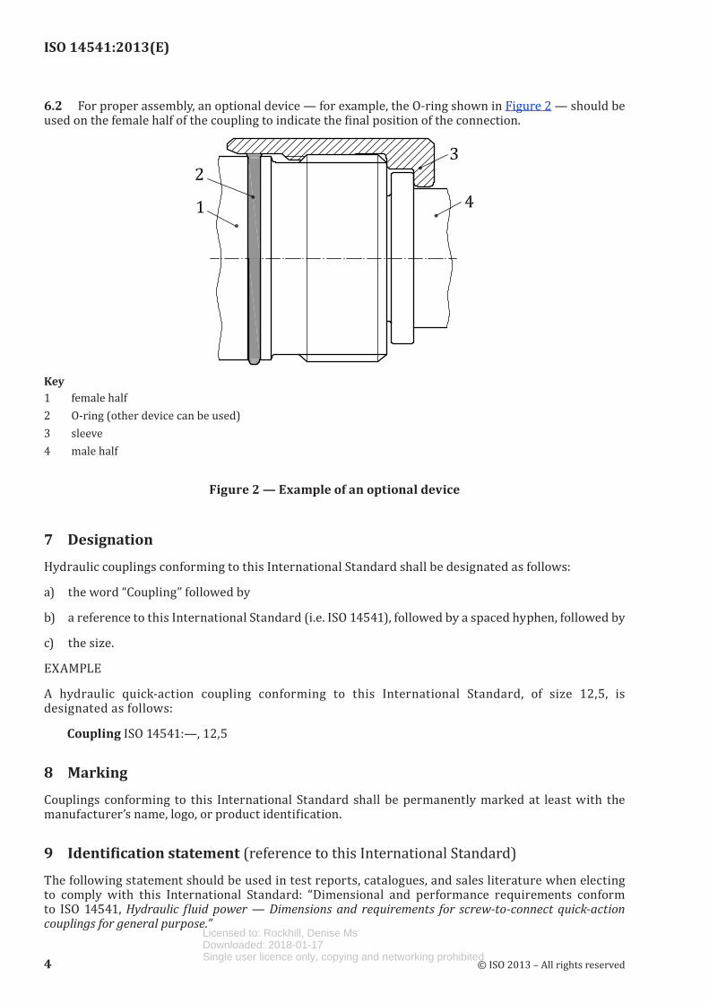
6.2 For proper assembly, an optional device — for example, the O-ring shown in Figure 2 — should be used on the female half of the coupling to indicate the final position of the connection.
Key1 female half2 O-ring (other device can be used)3 sleeve4 male half
Figure 2 — Example of an optional device
7 Designation
Hydraulic couplings conforming to this International Standard shall be designated as follows:
a) the word “Coupling” followed by
b) a reference to this International Standard (i.e. ISO 14541), followed by a spaced hyphen, followed by
c) the size.
EXAMPLE
A hydraulic quick-action coupling conforming to this International Standard, of size 12,5, is designated as follows:
Coupling ISO 14541:—, 12,5
8 Marking
Couplings conforming to this International Standard shall be permanently marked at least with the manufacturer’s name, logo, or product identification.
9 Identification statement (reference to this International Standard)
The following statement should be used in test reports, catalogues, and sales literature when electing to comply with this International Standard: “Dimensional and performance requirements conform to ISO 14541, Hydraulic fluid power — Dimensions and requirements for screw-to-connect quick-action couplings for general purpose.”
4 © ISO 2013 – All rights reserved
Licensed to: Rockhill, Denise MsDownloaded: 2018-01-17Single user licence only, copying and networking prohibited

ISO 14541:2013(E)
Bibliography
[1] ISO 4397, Fluid power connectors and associated components — Nominal outside diameters of tubes and nominal hose sizes
© ISO 2013 – All rights reserved 5
Licensed to: Rockhill, Denise MsDownloaded: 2018-01-17Single user licence only, copying and networking prohibited

ISO 14541:2013(E)
© ISO 2013 – All rights reserved
ICS 23.100.40Price based on 5 pages Licensed to: Rockhill, Denise Ms
Downloaded: 2018-01-17Single user licence only, copying and networking prohibited


![ISO 9001-2008.ppt [Read-Only] - ASQ-1302 · ISO 9001:2008 Changes to the New ... 7.5.1 Control of Production and Service Provision ... Note removed: Reference to ISO 10011 Added Note:](https://static.fdocuments.us/doc/165x107/5b3efa3c7f8b9af46b8b9711/iso-9001-2008ppt-read-only-asq-iso-90012008-changes-to-the-new-751.jpg)


![TACOTHERM DUAL PIKO - Heating, Cooling & Solar … · Stainless steel solder ... DIN-ISO 1302 Datum ... Toleranzen ISO 2768 TacoTherm Dual Piko Material: Gewicht: [SW-Masse] g g Blatt-Nr.](https://static.fdocuments.us/doc/165x107/5b83404a7f8b9a23668cb4ff/tacotherm-dual-piko-heating-cooling-solar-stainless-steel-solder-din-iso.jpg)