INTERNATIONAL INTERCONNECTION FORUM FOR SERVICES … · INTERNATIONAL INTERCONNECTION FORUM FOR...
56
international ip interconnection “Technical Interconnection Model for International Voice Services”, Release 5.0, May 2012 1 I NTERNATIONAL I NTERCONNECTION FORUM FOR SERVICES OVER I P (i3 FORUM) (www.i3forum.org) Source: Workstream “Technical Aspects” i3 Forum Keyword: Voice over IP, Interconnect, Signalling, Coding Technical Interconnection Model for International Voice Services (Release 5.0) May 2012 This document updates and replaces the i3 Forum document “Technical Interconnection Model for Bilateral Voice Services” (Release 4.0, May 2011). Date Rel. Subject/Comment 14 th May 2012 5 Addition of operational guidelines for wideband codecs; complete revision of Sec. 11 on QoS measurement 22 nd May 2011 4 Addition of IPV6; restructuring and enhancing Security Section 10 th May 2010 3 Proposal of QoS control mechanism based on RTCP 5 th May 2009 2 Addition of Sigtran and QOS section 15 th May 2008 1 First Draft of the document
Transcript of INTERNATIONAL INTERCONNECTION FORUM FOR SERVICES … · INTERNATIONAL INTERCONNECTION FORUM FOR...

international ip interconnection
“Technical Interconnection Model for International Voice Services”, Release 5.0, May 2012 1
INTERNATIONAL INTERCONNECTION FORUM FOR SERVICES OVER IP
(i3 FORUM)
(www.i3forum.org) Source: Workstream “Technical Aspects” i3 Forum Keyword: Voice over IP, Interconnect, Signalling, Coding
Technical Interconnection Model for International Voice Services
(Release 5.0) May 2012
This document updates and replaces the i3 Forum document “Technical Interconnection Model for Bilateral Voice Services” (Release 4.0, May 2011).
Date Rel. Subject/Comment
14th May 2012 5 Addition of operational guidelines for wideband codecs; complete revision of Sec. 11 on QoS measurement
22nd May 2011 4 Addition of IPV6; restructuring and enhancing Security Section 10th May 2010 3 Proposal of QoS control mechanism based on RTCP 5th May 2009 2 Addition of Sigtran and QOS section 15th May 2008 1 First Draft of the document

international ip interconnection
“Technical Interconnection Model for International Voice Services”, Release 5.0, May 2012 2
EXECUTIVE SUMMARY In order to allow a worldwide and unrestrained migration to IP of the thousands of existing TDM International voice interconnections, this document aims to specify, on the basis of existing standards/recommendations issued by international bodies (e.g. ITU-T, ETSI, IETF), a unique network architecture capable of supporting one (or a limited number of) interconnection model(s) for the implementation of trusted, secure and QoS compliant VoIP interconnection between International Wholesale Carriers. In order to achieve this goal, the scope of the documents covers all the relevant technical issues e.g.:
transport protocols/capabilities, including IPv6 compliance; signaling protocols (including SIGTRAN protocol for the support of mobile applications); media codec schemes; QoS levels with measurements and performance needs; E.164-based addressing schemes Security Accounting and Charging.
The specification of the VoIP and TDM interconnections of the international switching facilities with the domestic networks is outside the scope of this initiative. Assuming a general reference configuration encompassing:
switching platforms fed with TDM traffic as well as VoIP traffic from the domestic fixed and mobile networks and capable to manage signaling and media information onto an IP transport layer;
border functions in order to separate IP domains enhancing service and network level of security; routing functions according to IP networking; transmission functions according to SDH/Ethernet –based systems and protocols;
and also considering the Public Internet as a global infrastructure, two main sets of configurations are recommended:
Private-oriented interconnection: when no unidentified third party is able to affect the bilateral VoIP service;
Public-oriented interconnection: when the VoIP traffic is mixed with other IP traffic coming from the Public Internet, thus allowing the gateways’ interfaces to be reached from unidentified third parties which can affect the service performance and quality.
Though several signaling protocols are available on the market, two protocols have been selected as appropriate in this scenario: SIP protocol as defined in IETF RFC 3261 and complementing documents and ISUP enabled SIP profile as recommended in ITU-T Q.1912.5. Media functions should assure transport for all the services and perform any required media stream conversions such as G.711 companding law conversion and transcoding between different codecs. In the scope of this initiative the G.711 codec and the set of G.729 codecs are considered mandatory. Security, both from the network and service perspective, has been considered as a primary requirement for international VoIP interconnection. As a result, it is strongly recommended that all voice traffic coming into / leaving the network operator passes through Border Functions, i.e. all IP packets (for signaling and media), crossing this bilateral voice interconnection, are originated and received by such Border Functions. Quality of Service parameters together with the relevant measurement points are defined for the Service Provider – Carrier relationship as well as for the Carrier to Carrier relationship. The identified parameters are pertinent to the transport layer (e.g., round trip delay, jitter, packet loss), to the service layer (e.g., MOSCQE, ALOC, ASR, NER, PGRD) and to the call attributes (e.g., CLI transparency). This deliverable is the fifth version of this technical interconnection document enhancing the sections related to wideband codes and quality of service measurement. With regard to first topic, operations guidelines are given. The section in relation to the quality of service has been completely redrafted proposing a new approach for meeting service provider requirements. A reference to the new i3 Forum document related to the IMS signalling interconnecting scenario has been added in section 7. Future versions will be released encompassing new features / functions in order to consider the evolution of services, equipment capabilities and international standards, in particular with relationship to quality of service capabilities.

international ip interconnection
“Technical Interconnection Model for International Voice Services”, Release 5.0, May 2012 3

international ip interconnection
“Technical Interconnection Model for International Voice Services”, Release 5.0, May 2012 4
Table of Contents
1 SCOPE OF THE DOCUMENT................................................................................................... 8
2 OBJECTIVE OF THE DOCUMENT........................................................................................... 8
3 ACRONYMS .............................................................................................................................. 9
4 REFERENCES......................................................................................................................... 12
5 GENERAL REFERENCE ARCHITECTURE........................................................................... 15
5.1 Service reference configuration ...................................................................................................... 15 5.1.1 Functions to be performed for the incoming domestic voice traffic .............................................. 16 5.1.2 Functions to be performed for the incoming voice international traffic......................................... 17 5.1.3 Functions to be performed for the SIGTRAN traffic ..................................................................... 17
5.2 Transport reference configuration .................................................................................................. 17
6 TRANSPORT FUNCTIONS..................................................................................................... 19
6.1 Internet Protocol Versions ............................................................................................................... 19
6.2 Transport functions for private-oriented interconnections .......................................................... 19 6.2.1 Layer 1 interconnection................................................................................................................ 20 6.2.2 Layer 2 interconnection................................................................................................................ 20 6.2.3 Layer 3 interconnection................................................................................................................ 20
6.3 Transport functions for public-oriented interconnection.............................................................. 21 6.3.1 Layer 1 / layer 2 direct interconnection sharing Public Internet traffic and VoIP.......................... 21 6.3.2 Indirect interconnection via the Public Internet ............................................................................ 21
6.4 Physical interconnection alternatives............................................................................................. 22 6.4.1 PDH-based transport systems ..................................................................................................... 22 6.4.2 SDH-based transport systems ..................................................................................................... 22 6.4.3 Ethernet-based transport systems ............................................................................................... 22 6.4.4 DWDM-based transport systems ................................................................................................. 22 6.4.5 Interconnection redundancy......................................................................................................... 22
6.5 Dimensioning requirements at the transport layer ........................................................................ 22
6.6 IP Routing and IP Addressing.......................................................................................................... 22 6.6.1 IP Routing .................................................................................................................................... 22 6.6.2 IP Addressing............................................................................................................................... 23
6.7 IP Packet marking ............................................................................................................................. 23 6.7.1 Distinguishing traffic classes ........................................................................................................ 23 6.7.2 IP Marking table ........................................................................................................................... 23 6.7.3 Traffic treatment ........................................................................................................................... 24
7 SIGNALING FUNCTIONS ....................................................................................................... 25
7.1 Functions for supporting signalling protocol SIP (IETF RFC 3261) ............................................. 25 7.1.1 Transport of SIP (IETF RFC 3261) signaling information ............................................................ 25 7.1.2 SIP signaling protocol profile........................................................................................................ 25 7.1.3 SIP Message support ................................................................................................................... 25 7.1.4 SIP Header support...................................................................................................................... 26

international ip interconnection
“Technical Interconnection Model for International Voice Services”, Release 5.0, May 2012 5
7.2 Functions for supporting signaling protocol SIP-I (ITU-T Rec. Q.1912.5) ................................... 28 7.2.1 Transport of SIP-I (ITU-T Q.1912.5) signaling information .......................................................... 28 7.2.2 SIP-I (ITU – T Q.1912.5) signaling protocol profile ...................................................................... 28 7.2.3 ISDN Supplementary services support by SIP-I .......................................................................... 28
7.3 Mapping among ISUP, SIP and SIP-I signaling protocols ............................................................. 28
7.4 Functions for supporting signalling protocol SIGTRAN ............................................................... 29 7.4.1 Identification of SIGTRAN adaptation protocol stack ................................................................... 29 7.4.2 SCTP............................................................................................................................................ 29 7.4.3 M2PA ........................................................................................................................................... 29 7.4.4 M3UA ........................................................................................................................................... 30 7.4.5 Security ........................................................................................................................................ 30
7.5 Function For Supporting IMS Signaling (Interconnecting Scenario only)................................... 30
8 MEDIA FUNCTIONS................................................................................................................ 31
8.1 Voice calls – protocol profiles ......................................................................................................... 31 8.1.1 Real Time Protocol / Real Time Control Protocol ........................................................................ 31
8.1.1.1 Real Time Protocol data header ........................................................................................... 31 8.1.1.2 Real Time Protocol Payload types........................................................................................ 31 8.1.1.3 Real Time Protocol data header additions............................................................................ 31 8.1.1.4 Real Time Protocol data header extensions ......................................................................... 31 8.1.1.5 Real Time Control Protocol report interval ............................................................................ 32 8.1.1.6 Sender Report/Receiver Report (SR/RR) extensions........................................................... 32 8.1.1.7 Source Description (SDES) use............................................................................................ 32 8.1.1.8 Security - security services and algorithms........................................................................... 32 8.1.1.9 String-to-key mapping........................................................................................................... 32 8.1.1.10 Congestion - the congestion control behaviour..................................................................... 32 8.1.1.11 Transport protocol ................................................................................................................. 32 8.1.1.12 Transport mapping................................................................................................................ 32 8.1.1.13 Encapsulation of Real Time Protocol packets, multiple Real Time Protocol data packets ... 32 8.1.1.14 IP/UDP/RTP Compression.................................................................................................... 32
8.2 Voice codecs ..................................................................................................................................... 32
8.3 Codecs supported for narrow band transmission ......................................................................... 33 8.3.1 Guidelines for engineering ........................................................................................................... 33
8.4 Codecs supported for wideband transmission .............................................................................. 33 8.4.1 Guidelines for engineering ........................................................................................................... 34 Bitrates and Modes for mandatory Wideband codecs................................................................................ 34
8.5 Codecs supported for low bit rate transmission............................................................................ 34 8.5.1 Transmission (occupied) bandwidth............................................................................................. 34 8.5.2 Voice quality considerations......................................................................................................... 35 8.5.3 Low bit rate codecs ...................................................................................................................... 35 8.5.4 Guidelines for engineering ........................................................................................................... 35
8.6 Codec/packetisation period use and transcoding guidelines ...................................................... 35 8.6.1 Voice quality estimation ............................................................................................................... 36 8.6.2 General guidelines ....................................................................................................................... 36
8.7 Fax calls – protocol profiles............................................................................................................. 36 8.7.1 Fax over IP guidelines.................................................................................................................. 37
8.8 Modem connections.......................................................................................................................... 38
8.9 MoIP guidelines ................................................................................................................................. 38

international ip interconnection
“Technical Interconnection Model for International Voice Services”, Release 5.0, May 2012 6
8.10 Support of 64k clear channel (ISDN)............................................................................................ 38
9 HANDLING OF EARLY MEDIA .............................................................................................. 39
9.1 Support of P-early media header ..................................................................................................... 39
9.2 No support of P-early media header................................................................................................ 39
10 SECURITY............................................................................................................................ 40
10.1 Network elements for border function......................................................................................... 40
10.2 Security Mechanisms .................................................................................................................... 40 10.2.1 Topology Hiding ........................................................................................................................... 40 10.2.2 Encryption .................................................................................................................................... 40 10.2.3 Authentication .............................................................................................................................. 40 10.2.4 Access Control Lists..................................................................................................................... 40 10.2.5 Reverse Path Filters..................................................................................................................... 40 10.2.6 Traffic policing .............................................................................................................................. 41 10.2.7 Application Level Relaying ........................................................................................................... 41 10.2.8 Deep Packet Inspection ............................................................................................................... 41 10.2.9 SRTP............................................................................................................................................ 41 10.2.10 DNSSEC................................................................................................................................... 41 10.2.11 Media Filtering .......................................................................................................................... 41 10.2.12 Firewalls ................................................................................................................................... 41 10.2.13 Intrusion Detection Systems..................................................................................................... 41 10.2.14 Device Hardening ..................................................................................................................... 41 10.2.15 Logging and Auditing................................................................................................................ 41 10.2.16 Security Information & Code Updates ...................................................................................... 41
10.3 Security Threats............................................................................................................................. 41
10.4 Recommendations Matrixes ......................................................................................................... 42 10.4.1 External Service Interfaces Recommendations ........................................................................... 42 10.4.2 Routing & Addressing Provisioning and Other Interfaces Recommendations ............................. 44
11 QUALITY OF SERVICE MEASUREMENTS........................................................................ 45
11.1 QoS parameter definitions............................................................................................................ 46 11.1.1 Parameters relevant to the transport layer................................................................................... 46 11.1.2 Parameters relevant to the service layer...................................................................................... 46
11.2 Implementing market quality requirements ................................................................................ 49 11.2.1 Transport Parameters .................................................................................................................. 49 11.2.2 Service Parameters...................................................................................................................... 49
11.3 Methodologies for QoS Measurements – Single Network Domain........................................... 49
11.4 Methodologies for QoS Measurements – Multiple Networks Domain ...................................... 50 11.4.1 Aggregation-based approach....................................................................................................... 50 11.4.2 Media Loopback approach........................................................................................................... 51
11.5 KPI computation for SLA / QoS reporting ................................................................................... 52
12 NUMBERING AND ADDRESSING SCHEME (E.164-BASED)........................................... 54
12.1 Numbering and addressing in E.164-based international interconnection ............................. 54
12.2 International numbering scheme in TDM network ..................................................................... 54

international ip interconnection
“Technical Interconnection Model for International Voice Services”, Release 5.0, May 2012 7
12.3 TEL URI addressing scheme ........................................................................................................ 54
12.4 SIP URI Addressing scheme......................................................................................................... 54
13 ACCOUNTING AND CHARGING CAPABILITIES .............................................................. 55
13.1 Call detail record format ............................................................................................................... 55

international ip interconnection
“Technical Interconnection Model for International Voice Services”, Release 5.0, May 2012 8
1 Scope of the document The scope of this document is to address all the technical issues for the implementation of trusted, secure and QoS compliant IP-based interconnection of Voice Services (encompassing ISDN, fax and modem connections) between International Wholesale Operators considering:
transport protocols/capabilities, including IPv6 compliance; signaling protocols; media schemes; QoS levels with measurements and performance needs; E.164 addressing schemes; Security issues; Accounting and Charging Issues.
The support of applications based on the usage of the SIGTRAN suite of protocols is also considered in this document. The results and deliverables of private and public standardization/specification bodies, such as ITU-T, IETF, ETSI, GSMA and 3GPP have been considered as well as it has been also verified the existence of any regulatory framework for international IP interconnection. As far as the network platform is concerned, the present, and the short-term achievable, status of the art of the vendors’ equipment has been considered. All domestic legal rules and obligations are out of the scope of this document. Though this document does not intend to address any specific IMS model, for the sake of consistency with widely used terminology, the IMS model naming conventions have been adopted for some functional blocks (e.g. border functions).
2 Objective of the document The objective of the document is to define, on the basis of existing standards, a unique network architecture capable to support one (or a limited number of) interconnection model(s) for international voice over IP services encompassing bilateral interconnection as well as voice hubbing services. Each interconnection model is fully described in terms of transport capabilities, signaling protocols, media schemes such as codecs, available QoS levels, available numbering/addressing schemes and available security capabilities. This deliverable is the fifth version of the document. Future versions will be released encompassing new features / capabilities to address the evolution of services, equipment capabilities and international standards. The i3 Forum released a set of companion documents dealing with the service description [1], testing [3], codec selection [4], security [94] and migration template [5] for international voice over IP interconnection. These documents are available at www.i3forum.org.

international ip interconnection
“Technical Interconnection Model for International Voice Services”, Release 5.0, May 2012 9
3 Acronyms 3pcc Third Party Call Control 3PTY Three-Party conference ACL Access Control List ACM Address Complete Message ACR Anonymous Call Rejection AF Assured Forwarding ALG Application Level Gateway ALOC Average Length Of Conversation ANM Answer Message AS Autonomous System ASR Answer Seizure Rate ATM Asynchronous Transfer Mode BA Behavior Aggregate BE Best Effort BFD Bidirectional Forwarding Detection BGCF Breakout Gateway Control Function BGP Border Gateway Protocol BSS Business Support System CAMEL Customised Applications for Mobile Enhanced Logic CBC Cipher Block Chaining CC Country Code CD Call Deflection during alerting CDR Call Detail Record CF Call Forwarding CIN Calling Party’s Number CLI Calling Line Identification CLIP Calling Line Identification Presentation CLIR Calling Line Identification Restriction COLP Connected Line identification Presentation COLR Connected Line identification Restriction CPN Called Party’s Number CPU Central Processing Unit CSCF Call Session Control Function CUG Closed user Group CW Call waiting DdoS Distributed Denial of Service DES Data Encryption Standard Diffserv Differentiated Services DNS Domain Name Service DNSSEC DNS Secure DoS Denial of Service DPO Dynamic Port Opening DSCP Differentiated Services Code Point DTMF Dual-Tone Multi-Frequency DWDM Dense Wavelength Division Multiplexing EF Expedite Forward EXP MPLS header EXPerimental use field FoIP Fax over IP GIC Group Identification Code GSDN Global Software Defined Network GSN Global Subscriber Number HW Hardware IAM Initial Address Message IBCF Interconnection Border Control Function I-BGF Interconnection Border Gateway Function IC Identification Code ICMP Internet Control Message Protocol IDS Intrusion Detection Systems IFP Internet Facsimile Protocol IFT Internet Facsimile Transfer IKE Internet Key Exchange IMS IP Multimedia Subsystem IP Internet Protocol IPSec IP Security IPv4 Internet Protocol Version 4 IPv6 Internet Protocol Version 6 ISDN Integrated Services Digital Network

international ip interconnection
“Technical Interconnection Model for International Voice Services”, Release 5.0, May 2012 10
ISUP ISDN User Part IVR Interactive Voice Response KPI Key Performance Indicator LBR Low Bit rate codec MEF Metro Ethernet Forum MF Multi-Field Classifier MGCF Media Gateway Control Function MGF Media Gateway Function MIME Multipurpose Internet Mail Extensions MNO Mobile Network Operator MoIP Modem over IP MOS Mean Opinion Scale MOSCQE Mean Opinion Score, Communication Quality Estimated MPLS Multiprotocol Label Switching MPLS-VPN Multiprotocol Label Switching – Virtual Private Network MTP Message Transfer Part (SS7) NAPT Network Address and Port Translation NAT Network Address Translation NDC National Destination Code NER Network Efficiency Ratio NNI Network to Network Interface NN National Number OCN Original Called Number OIP Originating Identity Presentation OIR Originating Identity Restriction OLO Other Licensed Operator OSS Operations Support System P-router Provider router PDH Plesiochronous Digital Hierarchy PE-router Provider Edge router PGRD Post Gateway Ringing Delay PHB Per-Hop Behaviour POS Packet Over SDH/Sonet PSTN Public Switched Telephone Network QoS Quality of Service R-Factor Rating-Factor RgN Redirecting Number RI Redirecting Information RTCP Real Time Control Protocol RTD Round Trip Delay RTP Real-Time Protocol SBC Session Border Controller SCCP Signaling Connection Control Part (SS7) SCTP Stream Control Transmission Protocol SDES Source Description SDH Synchronous Digital Hierarchy SDP Session Description Protocol SGF Signaling Gateway Function SIP Session Initiation Protocol SIGTRAN Signaling Transport suite of Protocols SIP URI SIP protocol Uniform Resource Identifier SIP-I SIP with encapsulated ISUP SIP-T SIP for Telephones SLA Service Level Agreement SN Subscriber Number SPRT Simple Packet Relay Transport SR/RR Sender Report/Receiver Report SRTP Secure RTP TCP Transmission Control Protocol TDM Time Division Multiplexing TE MPLS Traffic Engineering MPLS tel-URI Telephone Uniform Resource Identifier TIP Terminating Identification Presentation TIR Terminating Identification presentation Restriction TISPAN Telecommunications and Internet converged Services and Protocols for Advanced Networking TLS Transport Layer Security TOS Type Of Service TSG Trunk Group TUP Telephone User Part

international ip interconnection
“Technical Interconnection Model for International Voice Services”, Release 5.0, May 2012 11
UDP User Datagram Protocol URI Uniform Resource Identifier URL Uniform Resource Locator UUI User-to-User Information UUS1 User to user signalling 1 VBD Voice Band Data VLAN Virtual Local Area Network VoIP Voice over IP VPN Virtual Private Network WB Wideband codec

international ip interconnection
“Technical Interconnection Model for International Voice Services”, Release 5.0, May 2012 12
4 References [1] i3 Forum “IP International Interconnections for Voice and other related services“ Release 3.0, June 2010 [2] i3 Forum “Service Value and Process of Measuring QoS KPIs“ Release 1.0, May 2010 [3] i3 Forum “Interoperability Test Plan for Bilateral Voice services” Release 2.0, May 2009 [4] i3 Forum White Paper “Voice Path Engineering in International IP based Voice Networks” Release 3.0, May 2011 [5] i3 Forum “Interconnection Form for International Voice Service” Release 3.0, May 2010 [6] i3 Forum White Paper “Mapping of Signaling protocols from ISUP to SIP, SIP-I” Release 3.0, May 2011 [7] ETSI 123.517 “TISPAN IP Multimedia Subsystem (IMS); Functional architecture” [8] IETF RFC 2474 “Definition of the Differentiated Services Field”, December 1998 [9] IETF RFC 2475 “An Architecture for Differentiated Services”, December 1998 [10] IETF RFC 3246 “Expedited Forwarding (Per-Hop Behavior)”, March 2002 [11] IETF RFC 3247 “Supplemental Information for the New Definition of the EF PHB (Expedited Forwarding Per-Hop
Behavior)”, March 2002 [12] IETF RFC 2597 “Assured Forwarding PHB Group”, June 1999 [13] IETF RFC 4594 “Configuration Guidelines for Diffserv Service Classes”, August 2006 [14] IETF RFC 1918 “Address Allocation for Private Internets”, February 1996 [15] IETF RFC 5880 “Bidirectional Forwarding Detection (BFD)”, June, 2010 [16] IETF RFC 4271 “A Border Gateway Protocol 4 (BGP-4)”, January 2006 [17] IETF RFC 3261 “SIP: Session Initiation Protocol”, June 2002 [18] IETF RFC 3966 “The tel URI for Telephone Numbers”, December 2004 [19] IETF RFC 3323 “A Privacy Mechanism for the Session Initiation Protocol (SIP)”, September 2002 [20] IETF RFC 3325 “SIP Extensions for Network-Asserted Caller Identity and Privacy within Trusted Networks”,
September 2002 [21] IETF RFC 4028 “Session Timers in the Session Initiation Protocol (SIP)”, April 2005 [22] ITU-T Recommendation Q1912.5 “Interworking between Session Initiation Protocol and Bearer Independent Call
Control or ISDN User Part, 2004 [23] IETF RFC 4566, “SDP: Session Description Protocol”, July 2006 [24] IETF RFC 3550 “RTP: A Transport Protocol for Real-Time Applications”, July 2003 [25] IETF RFC 3551, “RTP Profile for Audio and Video Conferences with Minimal Control”, July 2003 [26] IETF RFC 3555, “MIME Type Registration of RTP Payload Formats”, July 2003 [27] IETF RFC 4733, “RTP Payload for DTMF Digits, Telephony Tones and Telephony Signals”, December 2006 [28] IETF RFC 4040, “RTP Payload Format for a 64 kbit/s Transparent Call”, April 2005 [29] IETF RFC 3362 “Real-time Facsimile (T.38) – image/t38 MIME Sub-type Registration,”, August 2002 [30] ITU-T T.38 Procedures for real-time Group 3 facsimile communication over IP networks, 1998 [31] IETF RFC 768 “User Datagram Protocol”, August 1980 [32] ITU-T Recommendation E.164 “The international public telecommunication numbering plan”, 1997 [33] ITU-T Recommendation G.729 “Coding of speech at 8 kbit/s using conjugate-structure algebraic-code-excited linear
prediction (CS-ACELP)”, 1996 [34] ITU-T Recommendation G.711 “Pulse Code Modulation (PCM) of Voice Frequencies”, 1988 [35] IETF RFC 5806 “Diversion Indication in SIP”, March 2010 [36] IETF RFC 4458 “Session Initiation Protocol (SIP) URIs for Applications such as Voicemail and Interactive Voice
Response (IVR)”, April 2006. [37] IETF RFC 3389 “Real-time Transport Protocol (RTP) Payload for Comfort Noise (CN)” September 2002 [38] IETF RFC 4733 “RTP Payload for DTMF Digits, Telephony Tones and Telephony Signals” December 2006 [39] IETF RFC 4867 “Real-Time Transport Protocol (RTP) Payload Format and File Storage Format for the Adaptive
Multi-Rate (AMR) and Adaptive Multi-Rate Wideband (AMR-WB) Audio Codecs April 2007 [40] IETF RFC 4749 “RTP Payload Format for the G.729.1 Audio Codec” October 2006 [41] IETF RFC 4855 “Media-Type Registration of RTP Payload Formats”, February 2007 [42] IETF RFC 4117 “Transcoding Services Invocation in the Session Initiation Protocol (SIP) Using Third Party Call
Control (3pcc)” (June 2005). [43] ITU-T Recommendation T.38 “Procedures for real-time Group 3 facsimile communication over IP networks”
(04/2007) [44] ITU-T Recommendation V.150 “Modem-over-IP networks: Foundation” (07/2003). [45] ITU-T Recommendation G.729 “Coding of speech at 8 kbit/s using conjugate-structure algebraic code excited
linear-prediction (CS-ALEP (01/07) [46] ITU-T Recommendation G.729 Annex A “Reduced complexity 8kbit/s CS-ALEP codec” (11/96) [47] ITU-T Recommendation G.729 Annex B Silence compression scheme for G.729 optimized for terminals conforming
to Recommendation V.70” (11/96) [48] ITU-T Recommendation G.729 Annex A and B [49] IETF RFC 2663 “IP Network Address Translator (NAT) Terminology and Considerations”, August 1999 [50] IETF RFC 2401 “Security Architecture for the Internet Protocol”, November 1998 [51] IETF RFC 2246 “The TLS Protocol”, January 1999 [52] IETF RFC 4306 “Internet Key Exchange (IKEv2) Protocol”, December 2005 [53] ITU-T Recommendation. G.703: “Physical/electrical characteristics of hierarchical digital interfaces”, November
2001;

international ip interconnection
“Technical Interconnection Model for International Voice Services”, Release 5.0, May 2012 13
[54] ITU-T Recommendation. G.704 “Synchronous frame structures used at 1544, 6312, 2048, 8448 and 44 736 kbit/s hierarchical”, October 1998;
[55] ITU-T Recommendation. G.705 “Characteristics of plesiochronous digital hierarchy (PDH) equipment functional”, October 2000;
[56] ITU-T G.707: Network Node Interface for the Synchronous Digital Hierarchy(SDH), 01/2007 [57] ANSI T1.105: SONET - Basic Description including Multiplex Structure, Rates and Formats [58] IETF RFC 1423 - Privacy Enhancement for Internet Electronic Mail: Part III: Algorithms, Modes, and Identifiers,
February 1993 [59] RFC 3986 “Uniform Resource Identifiers (URI): Generic Syntax”, January 2005 [60] ITU-T Recommendation G.821 “Error Performance of an international digital connection operating at the bit rate
below the primary rate and forming part of an Integrated Services Digital Network”, December 2002 [61] ITU-T Recommendation Y.1540 “Internet Protocol Data Communications Services - IP Packet Transfer and
availability performance parameters”, November 2007 [62] ITU-T Recommendation E. 411 “International Network Management – Operational guidance”, March 2000 [63] ITU-T Recommendation E.425 “Network Management – Checking the quality of the international telephone service.
Internal automatic observations”, March 2002 [64] ITU-T Recommendation E.437 “Comparative metrics for network performance management”, May 1999 [65] ITU-T Recommendation P.10 “Vocabulary of terms on telephone transmission quality and telephone sets”,
December 1998 [66] ITU-T Recommendation G.107 “The E model, a computational model for use in transmission planning”, March 2005 [67] ETSI EG 202 057-2 “Speech processing transmission and quality aspects (STQ); user related QoS parameter
definitions and measurements; Part 2: Voice Telephony, Group 3 Fax, modem data services and SMS”; October 2005
[68] ITU-T Recommendation V.152 “Procedures for supporting voice-band data over IP networks” , January 2005. [69] ITU-T Recommendation Q.767, “Specification of Signaling System No.7, Application of the User Part of CCITT
Signaling System No.7 for International Interconnection ISDN”, 1991 [70] IETF RFC 3393 “IP Packet Delay Variation Metric for IP Performance Metrics (IPPM)”, November 2002 [71] IETF RFC 4960 “Stream Control Transmission Protocol” [72] IETF RFC 4166 “Telephony Signaling Transport over Stream Control Transmission Protocol (SCTP) Applicability
Statement“, February 2006 [73] IETF RFC 4165 “Signaling System 7 (SS7) Message Transfer Part 2 (MTP2) - User Peer-to-Peer Adaptation Layer
(M2PA)“, September 2005 [74] IETF RFC 3332 & 4666 “Signaling System 7 (SS7) Message Transfer Part 3 (MTP3) - User Adaptation Layer
(M3UA)”, September 2006 [75] IETF RFC 3788 “Security Considerations for Signaling Transport (SIGTRAN) Protocols”, June 2004 [76] IETF RFC 3960 “Early Media and Ringing Tone Generation in the Session Initiation Protocol (SIP)”, December
2004 [77] 3GPP TS 29.163 “Interworking between the IP Multimedia (IM) Core Network (CN) subsystem and Circuit Switched
(CS) networks” & TS 29.527 “TISPAN; Endorsement of the SIP-ISUP Interworking between the IP Multimedia (IM) Core Network (CN) subsystem and Circuit Switched (CS) networks”
[78] 3GPP TS 29.164 “Interworking between the 3GPP CS domain with BICC or ISUP as signaling protocol and external SIP-I networks”
[79] IETF RFC 2508 “Compressing IP/UDP/RTP Headers for Low-Speed Serial Links”, February 1999. [80] IETF RFC 3095 “Robust Header Compression (ROHC): Framework and four profiles: RTP, UDP, ESP, and
uncompressed”, July 2001. [81] IETF RFC 3311 “The Session Initiation Protocol (SIP) UPDATE Method”, September 2002 [82] IETF RFC 2976 “The SIP INFO Method”, October 2000 [83] IETF RFC 3262 “Reliability of Provisional Responses in the Session Initiation Protocol (SIP)”, June 2002 [84] IETF RFC 3428 “Session Initiation Protocol (SIP) Extension for Instant Messaging”, December 2002 [85] IETF RFC 3903 “Session Initiation Protocol (SIP) Extension for Event State Publication”, October 2004 [86] IETF RFC 3515 “The Session Initiation Protocol (SIP) Refer Method”, April 2003 [87] IETF RFC 3265 “Session Initiation Protocol (SIP)-Specific Event Notification”, June 2002 [88] IETF RFC 3326 “The Reason Header Field for the Session Initiation Protocol (SIP)”, December 2002 [89] IETF RFC 4193 “Unique Local IPv6 Unicast Addresses”, October 2005 [90] IETF RFC 4760 “Multiprotocol Extensions for BGP-4”, January 2007 [91] IETF RFC 2545 “Use of BGP-4 Multiprotocol Extensions for IPv6 Inter-Domain Routing”, March 1999 [92] IETF RFC 5881 “Bidirectional Forwarding Detection (BFD) for IPv4 and IPv6 (Single Hop)”, June 2010 [93] ITU-T Recommendation Y.1541, “Network performance objectives for IP-based services”, (02/2006) [94] I3 Forum “Technical White Paper on Security for IP Interconnection”, Release 1.0, May 2011 [95] IETF RFC 3711 “The Secure Real-time Transport Protocol (SRTP)”, March 2004 [96] IETF RFC 4033 “DNS Security Introduction and Requirements”, March 2005 [97] IETF RFC 4034 “Resource Records for the DNS Security Extensions”, March 2005 [98] IETF RFC 4035 “Protocol Modifications for the DNS Security Extensions”, March 2005 [99] IETF RFC 5009 “Private Header (P-Header) Extension to the Session Initiation Protocol (SIP) for Authorization of
Early Media”, September 2007. [100] ETSI EN 300 175-8 V2.4.0 “Digital Enhanced Cordless Telecommunications (DECT) Common Interface (CI)”,
2011-12 [101] GSMA PRD IR.36 “Adaptive Multirate Wide Band version 1.0”, December 2011

international ip interconnection
“Technical Interconnection Model for International Voice Services”, Release 5.0, May 2012 14
[102] ITU-T Recommendation T.38 “Procedures for real-time Group 3 facsimile communication over IP networks” 03/1998.
[103] ITU-T Recommendation T.38 “Procedures for real-time Group 3 facsimile communication over IP networks” 09/2010
[104] GSMA AA.81, “Packet Voice Interconnection Service Schedule to AA.80” and related approved change request [105] IETF RFC 2328,”OSPF Version 2”, April 1998 [106] IETF RFC 4855 “Media Type Registration of RTP Payload Formats”, February 2007 [107] IETF RFC 3264 “An Offer/Answer Model with the Session Description Protocol (SDP)”, June 2002 [108] IETF RFC 3611 “RTP Control Protocol Extended Reports (RTCP XR)”, November 2003 [109] I3 Forum “Interconnection IMS Signaling Profile”, Release 1.0, May 2012
international ip interconnection
“Technical Interconnection Model for International Voice Services”, Release 5.0, May 2012 15
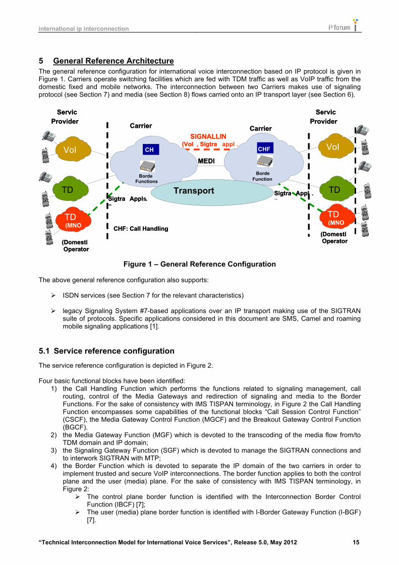
5 General Reference Architecture The general reference configuration for international voice interconnection based on IP protocol is given in Figure 1. Carriers operate switching facilities which are fed with TDM traffic as well as VoIP traffic from the domestic fixed and mobile networks. The interconnection between two Carriers makes use of signaling protocol (see Section 7) and media (see Section 8) flows carried onto an IP transport layer (see Section 6).
Figure 1 – General Reference Configuration
The above general reference configuration also supports:
ISDN services (see Section 7 for the relevant characteristics) legacy Signaling System #7-based applications over an IP transport making use of the SIGTRAN
suite of protocols. Specific applications considered in this document are SMS, Camel and roaming mobile signaling applications [1].
5.1 Service reference configuration
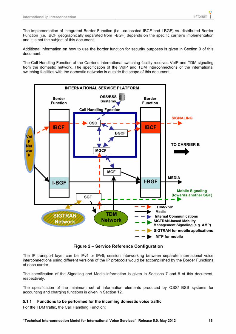
The service reference configuration is depicted in Figure 2. Four basic functional blocks have been identified:
1) the Call Handling Function which performs the functions related to signaling management, call routing, control of the Media Gateways and redirection of signaling and media to the Border Functions. For the sake of consistency with IMS TISPAN terminology, in Figure 2 the Call Handling Function encompasses some capabilities of the functional blocks “Call Session Control Function” (CSCF), the Media Gateway Control Function (MGCF) and the Breakout Gateway Control Function (BGCF).
2) the Media Gateway Function (MGF) which is devoted to the transcoding of the media flow from/to TDM domain and IP domain;
3) the Signaling Gateway Function (SGF) which is devoted to manage the SIGTRAN connections and to interwork SIGTRAN with MTP;
4) the Border Function which is devoted to separate the IP domain of the two carriers in order to implement trusted and secure VoIP interconnections. The border function applies to both the control plane and the user (media) plane. For the sake of consistency with IMS TISPAN terminology, in Figure 2:
The control plane border function is identified with the Interconnection Border Control Function (IBCF) [7];
The user (media) plane border function is identified with I-Border Gateway Function (I-BGF) [7].
Carrier A
Border Function
s
Border Function
s
Carrier B
(Domestic Operator)
TDM
VoIP
TDM
VoIP
Service Provider
A
Service Provider
B
(Domestic Operator)
CHF
CHF
CHF: Call Handling Function
MEDIA
SIGNALLING ( VoI
P , Sigtran
appls
.)
Sigtran
Appls
. Sigtran
Appls
.
TDM (MNO)
TDM (MNO)
Carrier A
Border Functions
Border Function
s
Carrier B
(Domestic Operator)
TDM TDM
VoIP VoIP
TDM TDM
VoIP VoIP
Service Provider
A
Service Provider
B
(Domestic Operator)
CHF
CHF
CHF: Call Handling Function
MEDIA
Transport Platform
SIGNALLING ( VoI
P , Sigtran
Sigtran
Appls . Sigtran
Appls
.
TDM (MNO)
TDM (MNO)
international ip interconnection
“Technical Interconnection Model for International Voice Services”, Release 5.0, May 2012 16
The implementation of integrated Border Function (i.e., co-located IBCF and I-BGF) vs. distributed Border Function (i.e. IBCF geographically separated from I-BGF) depends on the specific carrier’s implementation and it is not the subject of this document. Additional information on how to use the border function for security purposes is given in Section 9 of this document. The Call Handling Function of the Carrier’s international switching facility receives VoIP and TDM signaling from the domestic network. The specification of the VoIP and TDM interconnections of the international switching facilities with the domestic networks is outside the scope of this document.
Figure 2 – Service Reference Configuration
The IP transport layer can be IPv4 or IPv6; session interworking between separate international voice interconnections using different versions of the IP protocols would be accomplished by the Border Functions of each carrier. The specification of the Signaling and Media information is given in Sections 7 and 8 of this document, respectively. The specification of the minimum set of information elements produced by OSS/ BSS systems for accounting and charging functions is given in Section 12.
5.1.1 Functions to be performed for the incoming domestic voice traffic For the TDM traffic, the Call Handling Function:
Call Handling Function
I-BGF
Border Function
Border Function
INTERNATIONAL SERVICE PLATFORM
VoIP
Networ
k
MEDIA
SIGNALING
TO CARRIER B
MGF
Internal Communications
MGCF
CSCF
BGCF
TDM/VoIP Signalling Media
OSS/BSS Systems
TDM Network
IBCF
I-BGF
IBCF
SIGTRAN Network
SGF
MTP for mobile applications
Mobile Signaling (towards another SGF)
SIGTRAN-based Mobility Management Signaling (e.g. AMP) SIGTRAN for mobile applications

international ip interconnection
“Technical Interconnection Model for International Voice Services”, Release 5.0, May 2012 17
receives the Common Channel Signaling #7 converts in suitable protocols for VoIP traffic; identifies the proper routing towards the egress port; controls the Media Getaways, which, in turn, convert the TDM media flows to RTP media flows; the signaling is sent to the IBCF which controls I-BGF identifying the involved I-BGF resources
where the RTP media flow has to be directed. For VoIP traffic, the Call Handling Function:
receives the proper signaling information (e.g. SIP, SIP-I); converts, if needed, to suitable protocols for VoIP traffic; identifies the proper routing towards the egress port; sends signaling to the IBCF identifying the I-BGF resources where the RTP media flow has to be
directed.
5.1.2 Functions to be performed for the incoming voice international traffic IBCF receives the signaling information (e.g. SIP, SIP-I) from the corresponding carrier and forwards this signaling information to the Call Handling Function. The Call Handling Function:
identifies the proper routing towards the egress port; performs signaling interworking, if needed; in case of delivering towards a TDM-based network, controls the identified Media Gateway
Functions for delivering the media information; in case of delivering towards a VoIP-based network, the signaling information is sent to the IBCF
which controls I-BGF identifying the involved I-BGF resources where the RTP media flow has to be directed.
5.1.3 Functions to be performed for the SIGTRAN traffic For the SIGTRAN traffic, the Signaling Gateway Function:
receives the proper signaling information; identifies the proper routing towards the egress port; performs, if needed, interworking between MTP and SIGTRAN; handles mobility protocols for interworking with wireless networks.
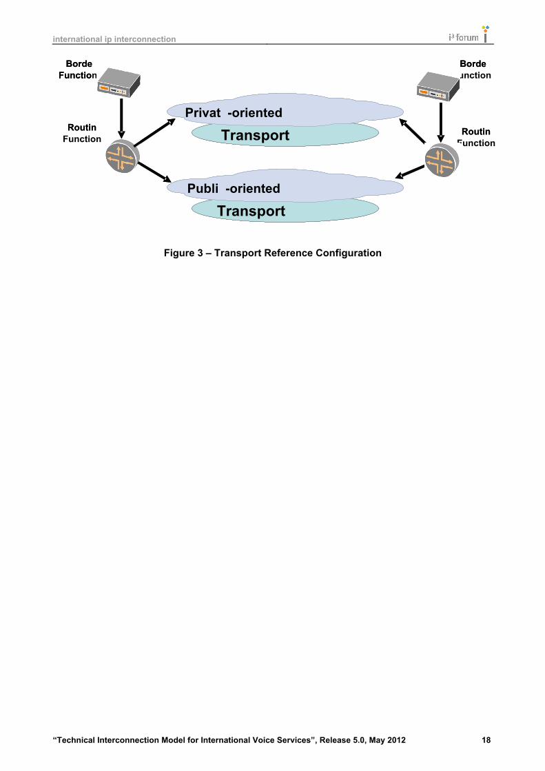
5.2 Transport reference configuration
Different transport configurations can be identified distinguishing between Private IP Interconnection and Public IP Interconnection. In turn, different options are viable for these two main categories. The definition of Private and Public IP Interconnection is given in Section 6 of this document. At the network layer IPv4 or IPv6 may be used and at the transmission layer either SDH transmission system or Ethernet-based systems are possible solutions. Additional information of these transmission systems are given in Section 6 of this document.
international ip interconnection
“Technical Interconnection Model for International Voice Services”, Release 5.0, May 2012 18
Figure 3 – Transport Reference Configuration
Transport Platform
Border Function
s
Border Function
s
Routing Function
s
Routing Function
s
Transport Platform
Private
- oriented Interconnection
Public
- oriented Interconnection
Transport Platform
Border
Border Functio
n
Routing
Routing
Transport Platform
Private
- oriented Interconnection
Public
- oriented Interconnection

international ip interconnection
“Technical Interconnection Model for International Voice Services”, Release 5.0, May 2012 19
6 Transport Functions This section recommends alternative reference transport configurations for implementing bilateral international VoIP interconnections. Assuming the Public Internet as a global infrastructure using either IPv4 or IPv6, interconnecting managed IP networks, carrying mixed types of traffic with publically announced IP addresses; two main sets of configurations are possible:
Private-oriented interconnection: where unidentified third parties are unable to affect the bilateral VoIP service;
Public-oriented interconnection: where VoIP traffic is mixed with other IP traffic coming from the
Public Internet, therefore allowing the border function or gateway interfaces to be reached by unidentified third parties who can affect service performance and quality.
This section exclusively deals with the Transport Functions. Signalling Functions and Media Functions are discussed in Sections 7 and 8, respectively.
6.1 Internet Protocol Versions
Bilateral international VoIP interconnections may occur using either IPv4 or IPv6 network protocols; in the context of this document IP refers to both IPv4 and IPv6 protocol versions. IPv4 refers to the commonly deployed protocol version using 32 bit addressing and IPv6 to the protocol version using 128 bit addressing. Since the introduction of the IPv6 addresses partitions the Public Internet into two separate networks, the IPv4 Public Internet and the IPv6 Public Internet, under the scope of bilateral international VoIP interconnections, the introduction of this addressing scheme requires carriers to be capable of managing both schemes for private as well as public interconnections. There are currently no generally deployed solutions that allow transparent interworking between these two IP protocol versions for international VoIP interconnection scenarios. Therefore the scenarios described within this section can use either IPv4 or IPv6 protocol versions but versions cannot be mixed on the same logical interconnect; both parties in the interconnection must be using the same protocol version. Border Function within each carrier network will require to be able to perform interworking between logical interconnects operating on IPv4 and IPv6. Private addresses discussed in this section refer to either RFC 1918 [14] addresses for IPv4 or RFC 4193 [89] for IPv6.
6.2 Transport functions for private-oriented interconnections
In the following subsections three private-oriented scenarios are given which are differentiating from each other at the interconnection layer: In order to be a private interconnection the following conditions have to be satisfied: 1) Only VoIP and/or private data services traffic is exchanged across the interconnection; 2) All the involved IP addresses (i.e. PE router interface, P router interface, and border function interface) cannot be reached from unidentified entities via the Public Internet. The IP addresses involved can be private or public, but they shall not be announced onto and reachable from the Public Internet. A hybrid configuration (i.e. carrier A using public not announced IP addresses and carrier B using private IP addresses), although technically feasible, is not recommended since it implies additional operational efforts for the management of the address space. 3) The VoIP traffic, from the PE router to the border function in a carrier’s domain, shall be secured, either physically or logically, from Internet Transit traffic.

international ip interconnection
“Technical Interconnection Model for International Voice Services”, Release 5.0, May 2012 20
This security can be achieved:
• physically: by implementing separated and dedicated networks for the two types of traffic. • logically: by implementing mechanism such as Virtual Private Networks (either layer 2, e.g., VLANs,
or layer 3, e.g., MPLS-VPN) and Tunneling (e.g. IP Sec). The QoS issues are dealt with in Section 10.
6.2.1 Layer 1 interconnection In this configuration a dedicated physical link (provided by one involved carrier, or by the two involved carrier, or by an identified third party) is implemented between PE routers or layer 2 switches, or directly between border functions.
Figure 44 – Layer 1 Private-oriented Interconnection Configuration
6.2.2 Layer 2 interconnection In this configuration a dedicated physical link (provided by one involved carrier, or by the two involved carrier, or by an identified third party) is implemented between PE routers or layer 2 switches, or directly between border functions passing through an Ethernet switch network run by a third party (e.g. telehouse/carrier hotel owner; Internet Exchange Point owner). The switch provider will assign specific VLANs for each interconnection allowing for the aggregation of several interconnections over the same physical link.
Figure 55 – Layer 2 Private-oriented Interconnection Configuration
6.2.3 Layer 3 interconnection In this configuration a dedicated virtual link is implemented between PE routers passing through a third party IP private network. The 3rd party IP network provider will establish an IP-VPN between the carriers’ networks and shall provide QoS mechanisms and shall guarantee appropriate SLAs. The 3rd party IP network provider and both carriers will require using the same IP protocol version: IPv4 or IPv6.
Figure 66 – Layer 3 Private-oriented Interconnection Configuration
Carrier A IP
network
Carrier B IP
network
PE router PE
router
Border Function
s
Border Function
s
Carrier A IP
network
Carrier A IP
network
Carrier B IP
network
Carrier B IP
network
PE router PE
router
Border Functio
n
Border Functio
n
Carrier A IP
network
Carrier B IP
network
PE router
PE router
Border Function
s Border Function
s
Layer
- 2 switch
Carrier A IP
network
Carrier A IP
network
Carrier B IP
network
Carrier B IP
network
PE router
PE router
Border Functio
n Border Functio
n
Layer
- 2 switch
Carrier A IP
network
Carrier B IP
network
PE router
PE router
Border Function
s Border Function
s
3rd party IP network
Carrier A IP
network
Carrier A IP
network
Carrier B IP
network
Carrier B IP
network
PE router
PE router
Border Functio
n Border
3rd party IP network

international ip interconnection
“Technical Interconnection Model for International Voice Services”, Release 5.0, May 2012 21
6.3 Transport functions for public-oriented interconnection
In the following subsections two public-oriented scenarios are given which differentiate each other at the interconnection layer. In order to retain the public interconnection feature it is assumed that some IP addresses to be used in these configurations can be reached from unidentified 3rd parties via the Public Internet either via IPv4 or IPv6.
6.3.1 Layer 1 / layer 2 direct interconnection sharing Public Internet traffic and VoIP In this configuration Internet traffic as well as VoIP traffic is exchanged either:
1) over the same physical link; 2) via a layer 2 switch.
In both cases, logical layer-2 traffic separation can be used by configuring VLAN based on IEEE 802.1q standard. Carriers may also use QoS mechanisms (e.g. Diffserv) to guarantee VoIP traffic performance over the interconnection. The IP addresses of the involved PE routers interfaces shall be public and can be announced over the Public Internet. Border function IP addresses shall be exchanged only between the two carriers (i.e., using the no-export BGP community attribute or static routing).
Figure 77 – Layer 1 / 2 Public-oriented Direct Interconnection Configuration
6.3.2 Indirect interconnection via the Public Internet In this configuration the VoIP traffic passes through the Public Internet, i.e. through a third (or multiple) Internet Transit providers. The IP addresses of the PE routers as well as those of the Border functions shall be public and they shall be announced over and reachable from the Public Internet. Both carriers and the entire path across the Public Internet, including all intermediary Transit providers, will require using the same version of the IP protocol, IPv4 or IPv6, for this logical interconnection.
Figure 88 – Indirect Public-oriented Interconnection Configuration
This configuration includes the case where PE routers are interconnected via an IPSec tunnel over the Public Internet. More information on encryption requirements are given in Section 10.
Carrier A IP
network
Carrier B IP
network
PE router
PE router
Internet Traffic
Border Function
s
Border Function
s Carrier A IP
network
Carrier A IP
network
Carrier B IP
network
Carrier B IP
network
PE router
PE router
Internet Traffic Voice Traffic
Border Functio
n
Border Functio
n
Carrier A IP
network
Carrier B IP
network
PE router
PE router
Border Function
s
Border Function
s
Carrier A IP
network
Carrier A IP
network
Carrier B IP
network
Carrier B IP
network
PE router
PE router
Border Functio
n
Border Functio
n

international ip interconnection
“Technical Interconnection Model for International Voice Services”, Release 5.0, May 2012 22
This scenario implies increased difficulty in managing QoS parameters than the interconnection configurations described in Section 6.2 since uncontrolled network segments are present from origin to destination of the call, but allows simpler and faster interconnection provisioning.
6.4 Physical interconnection alternatives
The physical interface of the interconnection can be either DWDM-based or PDH-based, SDH POS – based or Ethernet-based (i.e. fast-Ethernet, gigabit-Ethernet or 10 gigabit-Ethernet).
6.4.1 PDH-based transport systems The ITU-T Recommendations G. Series shall be considered as reference documents: ITU-T Rec. G.703 [53], G.704 [54] and G.705 [55].
6.4.2 SDH-based transport systems The ITU-T Recommendations G. Series shall be considered as reference documents: ITU T Rec. G.707 [56] For North America another reference document is ANSI T1.105 [57]
6.4.3 Ethernet-based transport systems The IEEE recommendations 802.3 for Ethernet communication together with enhanced Ethernet technologies such as fast-Ethernet, gigabit-Ethernet and 10 gigabit-Ethernet have to be considered (e.g. ISO/CIE 8802-3). This includes MEF standards for Carrier Ethernet connections.
6.4.4 DWDM-based transport systems For the public interconnection configurations, a DWDM channel can be provisioned for interconnecting two carries.
6.4.5 Interconnection redundancy The level of redundancy of a specific interconnection can be enhanced by increasing the number of involved Border Functions, by increasing the number of involved PE routers using geographical separation or by increasing the number of diverse network links involved.
6.5 Dimensioning requirements at the transport layer
In order to ensure that, at the interconnection, sufficient capacity is present with the highest level of confidence, a dimensioning scheme with an over-provisioning factor is suggested. In the following table, the bandwidth to be allocated per call is given for the most common codecs:
Codec Packetisation (msec.)
IPv4 Bandwidth (kbit/s)
IPv6 Bandwidth (kbit/s)
G.711 20 104.720 113.520 G.729 20 43.120 51.920 G.729 40 25.960 30.360
Note: the IPv4 and IPv6 bandwidth values of the above table consider the bandwidth of the codec plus the overhead of the Ethernet, IPv4 or IPv6, UDP and RTP protocols and assume a value equal to 10% as over-provisioning factor.
6.6 IP Routing and IP Addressing
6.6.1 IP Routing For all the above interconnection configurations, it is sufficient to announce only those IP addresses that need to be reached by the interconnecting carrier. The dynamic BGP protocol [16] [90] [91] or a static routing can be used to exchange IP routes or provision routing between carriers’ networks. If the BGP protocol is used, two cases have to be considered:
international ip interconnection
“Technical Interconnection Model for International Voice Services”, Release 5.0, May 2012 23
a) direct AS (Autonomous System) connection (see Sections 6.2.1, 6.2.2, 6.3.1): the NO_EXPORT
communities attribute shall be set; b) indirect AS connection (see Sections 6.2.3, 6.3.2): the NO_EXPORT communities attribute shall not
be set. It is recommended to tune BGP timer parameters to appropriate values for the specific implementation, to ensure timely failure detection and convergence suitable for VoIP traffic. In addition, BFD [15] [92] can also be used to speed up link failure detection and subsequent protocol convergence.
6.6.2 IP Addressing The IPv4 protocol addressing scheme shall be supported. The IPv6 protocol addressing scheme is optional and can be agreed on a bilateral basis. If public addresses are used, then the carriers will use only IP addresses assigned by IANA or related bodies. If private addresses [14] [89] are used, the bilateral agreement has to specify the IP addressing scheme.
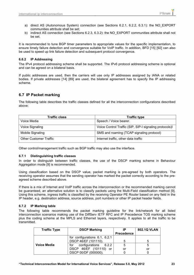
6.7 IP Packet marking
The following table describes the traffic classes defined for all the interconnection configurations described above:
Traffic class Traffic type Voice Media Speech / Voice bearer.
Voice Signaling Voice Control Traffic (SIP, SIP-I signaling protocols)I
Mobile Signaling SMS and roaming (TCAP signaling protocol)
Other Customer Traffic Internet traffic, other data traffic
Other control/management traffic such as BGP traffic may also use the interface.
6.7.1 Distinguishing traffic classes In order to distinguish between traffic classes, the use of the DSCP marking scheme in Behaviour Aggregation mode [9] is recommended. Using classification based on the DSCP value, packet marking is pre-agreed by both operators. The receiving operator assumes that the sending operator has marked the packet correctly according to the pre-agreed scheme described above. If there is a mix of Internet and VoIP traffic across the interconnection or the recommended marking cannot be guaranteed, an alternative solution is to classify packets using the Multi-Field classification method [9]. Using this scheme, ingress traffic is classified by the receiving Operator PE Router based on any field in the IP header, e.g. destination address, source address, port numbers or other IP packet header fields.
6.7.2 IP Marking table The following table recommends the packet marking guideline for the link/network for all listed interconnection scenarios making use of the DiffServ IETF RFC and IP Precedence TOS marking scheme plus the coding scheme at the MPLS and Ethernet layers, respectively. It applies to all the traffic to be transmitted.
Traffic Type DSCP Marking IP Precedence
802.1Q VLAN
for configurations 6.1, 6.2.1 DSCP 46/EF (101110).
5
5
Voice Media for configurations 6.2.2 DSCP 46/EF (101110) or DSCP 00/DF (000000).
5 or 0
5 or 0

international ip interconnection
“Technical Interconnection Model for International Voice Services”, Release 5.0, May 2012 24
for configurations 6.1, 6.2.1 DSCP 26/AF31 (011010) or DSCP 46/EF (101110)
3 or 5
3 or 5
Voice Signaling, for configurations 6.2.2 DSCP 26/AF31 (011010) or DSCP 46/EF (101110) or DSCP 00/DF (000000)
3 or 5
or 0
3 or 5
or 0 for configurations 6.1, 6.2.1 DSCP 26/AF31 (011010) or DSCP 46/EF (101110)
3 or 5
3 or 5 SIGTRAN for
Mobile Signaling
for configurations 6.2.2 DSCP 26/AF31 (011010) or DSCP 46/EF (101110) or DSCP 00/DF (000000)
3 or 5
or 0
3 or 5
or 0 Other traffic DSCP 00/DF (000000). 0 0
The marking for the other control/management traffic depends on the specific network implementation.
6.7.3 Traffic treatment For interconnection configurations specified in Sections 6.2 and 6.3.1, voice media traffic leaving the sending Border Function towards the receiving Border Function should be treated according to the Expedited Forwarding Per-Hop Behavior [10], [11]. For the interconnection configuration specified in Section 6.3.2, voice media traffic leaving the sending Border Function towards the sending PE router is treated either according to the Expedited Forwarding Per-Hop Behavior [10], [11] or according to Default forwarding Per-Hop Behavior [1] that is, it becomes ‘best effort‘ forwarding. For interconnection configurations specified in Sections 6.2 and 6.3.1, voice signaling traffic leaving the sending Border Function towards the receiving Border Function should be treated according to the Expedite Forwarding Per-Hop Behavior [10], [11], or alternatively according to the Assured Forwarding Per-Hop Behavior [12]. The industry conventionally uses both AF and EF PHB for signaling traffic. Where one carrier internally uses AF and the other interconnecting carrier internally uses EF, then bilateral agreement is required on how to configure the interconnection to re-mark the packets appropriately. Further if different DSCP markings within the AF class are used, bilateral agreement will be required regarding as to whether the different marking is maintained or traffic re-marked as described for AF / EF marking. For the interconnection configuration specified in Section 6.3.2, signalling traffic leaving the sending Border Function towards the sending PE router is treated either according to:
• the Expedite Forwarding Per-Hop Behavior, as specified in RFC 3246 [10] and RFC 3247 [11]; • the Assured Forwarding Per-Hop Behavior as specified in RFC 2597 [12]; • the Default forwarding PHB , as specified in IETF RFC 2474 [8].

international ip interconnection
“Technical Interconnection Model for International Voice Services”, Release 5.0, May 2012 25
7 Signaling Functions The interconnections described in this document shall support either a basic SIP profile (as described in Section 7.1) or an ISUP enabled SIP profile (as described in Section 7.2) or SIGTRAN for additional signaling purposes such as SMS, CAMEL and mobile roaming (as described in Section 7.4).
7.1 Functions for supporting signalling protocol SIP (IETF RFC 3261)
This subsection describes the basic SIP profile.
7.1.1 Transport of SIP (IETF RFC 3261) signaling information The SIP protocol can be transported over UDP [31], TCP or SCTP. IETF RFC 3261 [17] defines that UDP is the default for SIP. In the scope of this document UDP shall be used as default. If a non-reliable transport implementation is used then TCP may be used based on bilateral agreements. There is also the possibility to use the newer transport protocol SCTP. Since support from vendors is not widely available at the date when this document is published, the use of SCTP is left as part of the specific bilateral agreement.
7.1.2 SIP signaling protocol profile The basic SIP profile shall comply with RFC 3261 [17] with the addition of the following considerations:
• The compact form of SIP shall not be used. • The Request-URI shall be set in accordance to Section 11. • The support of IETF RFC 4028 [21], which addresses SIP Timers specification, is optional. The
carrier receiving the INVITE message shall comply with IETF RFC 3261 [17] section 16.8 if IETF RFC 4028 [21] is not supported.
• The P-Asserted-Identity header defined in RFC 3325 [20] shall be supported. • The Privacy header defined in RFC 3323 [19] shall be supported. • The Diversion header defined in RFC 5806 [35] shall be supported. • The following body types shall be supported:
application/sdp • The following body types may be supported:
application/dtmf application/dtmf-relay multipart/mixed.
Subject to bilateral agreement, the carrier may or may not apply privacy before forwarding SIP messages over the interconnection interface. When applying privacy, it shall be applied as follows: Originating User Privacy Request Originating Carrier behaviour CIN Known, Presentation not restricted Forward CIN in From, Contact and P-Asserted-
Identity headers CIN Known, Presentation restricted Use “Anonymous” in From and Contact headers. CIN not known Use “Unavailable” in From and Contact headers.
Note: when a SIP message is passed to an untrusted domain, the inclusion or removal of the P-Asserted-Identity header shall be determined by consulting the Privacy header. If a Privacy header is not present, then it is recommended to include the P-Asserted-Identity header, but in this case bi-lateral agreement should dictate final treatment (IETF RFC 3325, 3323). When the SIP message is passed to a trusted domain, the P-Asserted-Identity header should not be removed ([IETF RFC 3325]).
7.1.3 SIP Message support The following table specifies how the SIP messages shall be supported.

international ip interconnection
“Technical Interconnection Model for International Voice Services”, Release 5.0, May 2012 26
# SIP Message Observations 1 REGISTER The REGISTER message is not needed in the scope of this document. 2 INVITE The INVITE message shall be supported as described in IETF RFC 3261
[17]. 3 ACK The ACK message shall be supported as described in IETF RFC 3261
[17]. 4 CANCEL The CANCEL message shall be supported as described in IETF RFC 3261
[17]. 5 BYE The BYE message shall be supported as described in IETF RFC 3261
[17]. 6 OPTIONS The OPTIONS messages shall be supported as described in IETF RFC
3261 [17]. SIP message OPTIONS can be used to probe reachability and availability as follows: periodic SIP OPTIONS messages are sent to the other party to check if the route is still valid; after several unanswered messages the route gets dropped. The use of this feature is subject to bilateral agreement.
7 UPDATE The UPDATE message described in IETF RFC 3311 [81] may be used subject to bilateral agreement
8 INFO The INFO message described in IETF RFC 2976 [82] may be used subject to bilateral agreement
9 PRACK The PRACK message described in IETF RFC 3262 [83] may be used subject to bilateral agreement
10 MESSAGE The MESSAGE message described in IETF RFC 3428 [84] may be used subject to bilateral agreement
PUBLISH The PUBLISH message described in IETF RFC 3903 [85] may be used subject to bilateral agreement
11 REFER The REFER message described in IETF RFC 3515 [86] may be used subject to bilateral agreement
12 SUBSCRIBE The SUBSCRIBE message described in IETF RFC 3265 [87] may be used subject to bilateral agreement
13 NOTIFY The NOTIFY message described in IETF RFC 3265 [87] may be used subject to bilateral agreement
7.1.4 SIP Header support The following table specifies how the SIP header shall be supported. # Header Observations 1 Accept The Accept header shall be used as defined in section 20.1 of RFC 3261 [17]
with the addition that accepting application/sdp is mandatory. 2 Accept-Encoding The Accept-Encoding header shall be used as defined in section 20.2 of
RFC3261 [17]. 3 Accept-Language The Accept-Language header shall be used as defined in section 20.3 of RFC
3261 [17]. Standard English language (en) is mandatory. 4 Alert-Info The Alert-Info header is not applicable in the scope of this document. 5 Allow The Allow header shall be used as defined in section 20.5 of RFC 3261 [17]
with the addition that it should be mandatory in all response messages (it reduces the number of messages exchanged).
6 Authentication-Info
The Authentication-Info header is not applicable in the scope of this document.
7 Authorization The Authorization header is not applicable in the scope of this document. 8 Call-ID The Call-ID header shall be used as defined in section 20.8 of RFC 3261 [17]. 9 Call-Info The support of Call-Info header is optional and should be agreed between the
interconnecting Carriers. 10 Contact The Contact header shall be used as defined in section 20.10 of RFC 3261
[17]. Privacy considerations might modify its value. 11 Content-
Disposition The Content-Disposition header shall be used as defined in section 20.11 of RFC 3261 [17].
12 Content-Encoding
The Content-Encoding header shall be used as defined in section 20.12 of RFC 3261 [17].
13 Content- The Content-Language header shall be used as defined in section 20.13 of

international ip interconnection
“Technical Interconnection Model for International Voice Services”, Release 5.0, May 2012 27
Language RFC 3261 [17]. 14 Content-Length The Content-Length header shall be used as defined in section 20.14 of RFC
3261 [17]. 15 Content-Type The Content-Type header shall be used as defined in section 20.15 of RFC
3261 [17]. Support for Content-Type of application/sdp is mandatory. 16 Cseq The Cseq header shall be used as defined in section 20.16 of RFC 3261 [17]. 17 Date The Date header shall be used as defined in section 20.17 of RFC 3261 [17]. 18 Error-Info The Error-Info header shall be used as defined in section 20.18 of RFC 3261
[17]. 19 Expires The Expires header shall be used as defined in section 20.19 of RFC 3261
[17]. 20 From The From header shall be used as defined in section 20.20 of RFC 3261.
Privacy considerations might modify its value. 21 In-Reply-To The In-Reply-To header shall be used as defined in section 20.21 of RFC
3261 [17]. 22 Max-Forwards The Max-Forwards header shall be used as defined in section 20.22 of RFC
3261 [17]. 23 Min-Expires The Min-Expires header shall be used as defined in section 20.23 of RFC
3261 [17]. 24 MIME-Version The MIME-Version header shall be used as defined in section 20.24 of RFC
3261 [17]. 25 Organization The Organization header shall be used as defined in section 20.25 of RFC
3261 [17]. 26 P-Asserted-
Identity The P-Asserted-Identity shall be used as defined in RFC 3325 [20].
27 Priority The Priority header shall be used as defined in section 20.26 of RFC 3261 [17].
28 Privacy The Privacy header shall be used as defined in RFC 3323 [19]. 29 Proxy-
Authenticate The Proxy-Authenticate header is not applicable in the scope of this document.
30 Proxy-Authorization
The Proxy-Authorization header is not applicable in the scope of this document.
31 Proxy-Require The Proxy-Require header is not applicable in the scope of this document. 32 Reason Header The Reason Header should be used as defined in IETF RFC 3326 [88]. 33 Record-Route The Record-Route header is not applicable in the scope of this document. 34 Reply-To The Reply-To header shall be used as defined in section 20.31 of RFC 3261
[17]. Privacy considerations might modify its value. 35 Require The Require header shall be used as defined in section 20.32 of RFC 3261
[17]. 36 Retry-After The Retry-After header shall be used as defined in section 20.33 of RFC 3261
[17]. 37 Route The Route header is not applicable in the scope of this document. 38 Server The Server header shall be used as defined in section 20.35 of RFC 3261
[17]. 39 Subject The Subject header shall be used as defined in section 20.36 of RFC 3261
[17]. 40 Supported The Supported header shall be used as defined in section 20.37 of RFC 3261
[17]. 41 Timestamp The Timestamp header shall be used as defined in section 20.38 of RFC
3261 [17]. 42 To The To header shall be used as defined in section 20.39 of RFC 3261 [17].
Privacy considerations might modify its value. 43 Unsupported The Unsupported header shall be used as defined in section 20.40 of RFC
3261 [17]. 44 User-Agent The User-Agent header shall be used as defined in section 20.41 of RFC
3261 [17]. 45 Via The Via header shall be used as defined in section 20.42 of RFC 3261 [17]. 46 Warning The Warning header shall be used as defined in section 20.43 of RFC 3261
[17]. 47 WWW-
Authenticate The WWW-Authenticate header is not applicable in the scope of this document.

international ip interconnection
“Technical Interconnection Model for International Voice Services”, Release 5.0, May 2012 28
7.2 Functions for supporting signaling protocol SIP-I (ITU-T Rec. Q.1912.5)
This subsection describes the ISUP-enabled SIP profile.
7.2.1 Transport of SIP-I (ITU-T Q.1912.5) signaling information See Section 7.1.1.
7.2.2 SIP-I (ITU – T Q.1912.5) signaling protocol profile This signaling protocol profile shall be in accordance with ITU-T Recommendation Q.1912.5 [22] Annex C Profile C.
7.2.3 ISDN Supplementary services support by SIP-I The implementation of SIP-I based interconnection is transparent for the support of ISDN bearer services, including video services, as well as ISDN Supplementary Services. Assuming ITU-T Q.767 [69] as the reference document for the identification of the ISDN bearer services to be supported onto an international circuit; namely:
Category: Circuit mode - 64 kbit/s unrestricted - Speech - 3,1 kHz audio
It is recommended that the same bearer capabilities are supported on an international IP link. The following listed Supplementary Services are part of the ISUP encapsulation mechanism and there is no need of additional interworking function:
- Calling Line Identification Presentation (CLIP) - Calling Line Identification Restriction (CLIR) - Connected Line Identification Presentation (COLP) - CLIP no screening - COLP no screening - Connected line Identification Restriction (COLR) - Call Deflection during alerting (CD) - Call Forwarding (CF)´ - Anonymous Call Rejection (ACR) - Reject Forward call (only if Call Forwarding indication is provided by ISUP) - Call waiting (CW) - Three-Party conference (3PTY) (depending on special situation via destination IP-network) - Closed user Group (CUG) - User to user signaling 1(UUS1)
As some ISDN services are delay sensitive, in order to meet standard quality levels, it is preferable to provide ISDN services via private-oriented interconnections (see Section 6.2). Video services based on 64 kbit/s unrestricted channel bearer capability are supported.
7.3 Mapping among ISUP, SIP and SIP-I signaling protocols
Mapping between ISUP and SIP, ISUP and SIP-I, or SIP and SIP-I is a complex area that needs to be taken into account to ensure optimum behavior for session control. Incorrect, inconsistent and/or otherwise ambiguous mappings can make the determination of root cause of issues within a carrier’s network difficult. They can potentially lead to improper re-route behaviors together with incorrect quality KPI calculations resulting in falsely SLA violation. The most straightforward case is ISUP to SIP-I in accordance with specification ITU Q1912.5, Annex C Profile C [22]. Essentially, as the ISUP is encapsulated within the SIP message, correct conveyance of the ISUP information is guaranteed. Where ISUP has to be mapped into SIP there are a number of standards but they differ and this has led to different vendors’ implementations. As a partial solution, the support of the Reason Header field in SIP is

international ip interconnection
“Technical Interconnection Model for International Voice Services”, Release 5.0, May 2012 29
recommended since it can alleviate the majority of mapping issues where ISUP disconnect cause values can be retrieved. It was the view of i3 Forum that these problems had to be addressed with urgency. For this reasons, i3 Forum jointly worked with 3GPP developing and supporting a new mapping (3GPP TS 29.163 v7.22.0) agreed in March 2011 and widely discussed in the companion signaling document the i3 Forum White Paper “Mapping of Signaling Protocols from ISUP to SIP, SIP-I” [6]. i3 Forum recommends this new mapping to be implemented by vendors, carriers and service providers.
7.4 Functions for supporting signalling protocol SIGTRAN
The suite of SIGTRAN protocols enable the transport of Signaling System #7 (SS7) messages over an IP transport layer as defined in Section 6. This section provides guidelines on the implementation of the following SIGTRAN protocols for inter-carrier connectivity.
7.4.1 Identification of SIGTRAN adaptation protocol stack Among the various SIGTRAN adaptation protocol stacks, for the interconnection between Signaling Gateways Functions (SGF), for the inter-carrier connectivity, the Message Transfer Part 2 Peer-to-Peer Adaptation Layer (M2PA) should be considered as the preferred solution since it is the only one with relaying capabilities (i.e. it is possible to continue SS#7 MTP traffic routing beyond the end-point of the M2PA connection). In addition, M2PA provides error discovery capability, enhancing network performance and availability. The Message Transfer Part 3 User Adaptation Layer (M3UA) may be used in the case when no relaying capability is needed (i.e. a SCCP connection with the corresponding carrier). In addition, M3UA does not protect against message loss, duplication or miss sequencing between Stream Control Transmission Protocol (SCTP) association. In all cases, SCTP shall be used between the IP layer and the SIGTRAN adaptation layers.
7.4.2 SCTP SCTP shall be supported as defined by IETF RFC 4960 [71] and IETF RFC 4166 [72].
7.4.3 M2PA If the transport of SS7 MTP3 signaling messages is required in a peer to peer architecture, such as SGF to SGF, then M2PA shall be implemented as defined by IETF RFC 4165 [73].
Figure 9 – M2PA Adaptation Layer

international ip interconnection
“Technical Interconnection Model for International Voice Services”, Release 5.0, May 2012 30
7.4.4 M3UA If the transport of any SS7 MTP3-User signaling, (e.g. SCCP) is required, then M3UA shall be implemented as defined by also IETF RFC 3332 [74] as short term implementation and IETF RFC 4666 [74] as target implementation.
Figure 10 – M3UA Adaptation Layer
7.4.5 Security For private interconnection configurations (Section 6.2), as these interconnections are by definition secure, no encryption is necessary. For public interconnection configurations (Section 6.3), as per IETF RFC 3788 [75], the support of IPsec is mandatory for all nodes running SIGTRAN protocols. TLS support is optional, see Section 11.
7.5 Function For Supporting IMS Signaling (Interconnecting Scenario only)
A profile of the IMS SIP signalling limited to the interconnecting scenario is given in [109].

international ip interconnection
“Technical Interconnection Model for International Voice Services”, Release 5.0, May 2012 31
8 Media Functions This section discusses the recommendations for the voice path, fax and voice band data for international IP voice interconnections. For more information of the voice path, please refer to the i3 Forum – Technical Whitepaper on Voice Path [4]. Media functions in International voice IP interconnections should ensure the following:
• Transport for all the services;
• Transcoding, where required and applicable.
An international IP voice interconnection shall support the following services: • Voice phone calls using different codecs;
• DTMF support;
• Fax connections;
• Modem connections.
These above listed services shall be accessible for both TDM and VoIP subscribers.
8.1 Voice calls – protocol profiles
For calls between two or more terminals the following protocol stack shall be used: − RTP protocol for real time media; − UDP protocol at the transport layer.
8.1.1 Real Time Protocol / Real Time Control Protocol The Real Time transport Protocol (RTP) and Real Time transport Control Protocol (RTCP) shall be used for international voice services as defined in IETF RFC 3550 [24]. According to RFC 3550 for particular applications the following items should be additionally defined:
• Profile definition; • Payload format specification.
In order to guarantee measurements of QoS parameters, RTP and RTCP flows have to be passed through end-to-end for the voice over IP connection except when media stream conversions such as transcoding or packetisation period transrating occurs. The profile that shall be used for international voice interconnection is defined in IETF RFC 3551 [25]. The list of protocol parameters defined in this RFC [25] that shall be used is given below.
8.1.1.1 Real Time Protocol data header RTP data header is defined in Section 2 of RFC 3551. The content of this section is endorsed.
8.1.1.2 Real Time Protocol Payload types The following RTP payload types shall be supported:
• G.711 A-law, G.711 µ-law, G.729, G.729a, b, ab, G.722, AMR-WB, as defined in Section 6, Table 4 of RFC 3551;
• Detailed definition of above mentioned and other supported codecs payload types in Sections 8.3- 8.5 of this document;
• Comfort Noise as defined in Section 4 of RFC 3389 [37]. (static PT 13 (8 kHz) or dynamic); • Telephone Events (DTMF tones) as defined in the Section 3.3 of IETF RFC 4733 [27] (dynamic). • Telephone tones as defined in the Section 4.4 of IETF RFC 2833 (dynamic);.
8.1.1.3 Real Time Protocol data header additions No RTP header additions will be used.
8.1.1.4 Real Time Protocol data header extensions Use of RTP data header extensions is not recommended.

international ip interconnection
“Technical Interconnection Model for International Voice Services”, Release 5.0, May 2012 32
8.1.1.5 Real Time Control Protocol report interval Recommended bandwidth allocation to RTCP reports would be 1.25% of session bandwidth for senders and 3.75% for receivers. Other bandwidth allocations are possible as described in Section 2 of IETF RFC 3551.
8.1.1.6 Sender Report/Receiver Report (SR/RR) extensions Generally no SR/RR extensions will be used. Optional extensions may be used if agreed bilaterally.
8.1.1.7 Source Description (SDES) use The SDES use is specified in IETF RFC 3551 [25] Section 2.
8.1.1.8 Security - security services and algorithms According to RFC 3550 [24] Section 9.1, the default encryption algorithm is the Data Encryption Standard (DES) algorithm in Cipher Block Chaining (CBC) mode, as described in Section 1.1 of RFC 1423 [58], except that padding to a multiple of 8 octets is indicated as described for the P-bit. In the scope of this document RTP encryption is not recommended.
8.1.1.9 String-to-key mapping No string to key will be used.
8.1.1.10 Congestion - the congestion control behaviour RTP and this profile may be used in different contexts: enhanced network services, or best effort services. Some congestion control guidelines to be introduced are in Section 2 of IETF RFC 3551 [25]. Under normal operational conditions congestion should be avoided by network engineering techniques.
8.1.1.11 Transport protocol The UDP as well as the TCP protocols are defined in RFC 3551 [25] section 2 as the transport layer. In the scope of this document only the UDP protocol shall be used as the RTP transport layer for voice services.
8.1.1.12 Transport mapping The standard mapping of RTP and RTCP addresses and ports at the transport layer is used as in RFC 3551 [25] Section 2 with the following recommendations:
RTP should use an even destination port number and the corresponding RTCP stream should use the next higher (odd) destination port number as described in RFC 3550 [24] Section 11;
symmetrical UDP protocol should be used (the same port numbers).
8.1.1.13 Encapsulation of Real Time Protocol packets, multiple Real Time Protocol data packets
Encapsulation of RTP packets in UDP protocol shall be used as defined in [24].
8.1.1.14 IP/UDP/RTP Compression Compressing IP/UDP/RTP Headers as described in RFC2508 [79] or RFC3095 [80] will reduce the bandwidth of the interconnection link and is recommended when bandwidth is restricted. Compression may not be available for IPv6 interconnections. When IP/UDP/RTP compression is used, the UDP checksum is not required for voice, hence compression to 2 bytes for RFC 2508 (or, typically, 3 bytes for RFC 3095 if available) is recommended for this purpose.
8.2 Voice codecs
Many different coding schemes have been defined, implemented and used for international voice service. In the scope of this document these codecs are divided into 2 categories: Mandatory codecs: the carrier shall be able to carry all voice media flows encoded as per any of the i3 forum recommended codecs, to be considered as mandatory in this context, and shall allow the negotiation of these codecs between both originating and terminating Service Providers. As a result, a carrier has to support all mandatory codecs listed in Table 1 in Sec. 8.3 below. Provided at least one of the mandatory codecs is present in the session description protocol (SDP) offer, and provided at least one of the mandatory

international ip interconnection
“Technical Interconnection Model for International Voice Services”, Release 5.0, May 2012 33
codecs is supported by both originating and terminating Service Providers, then codec negotiation is guaranteed to be successful. For any transcoding related matter see Section 8.6.2. Optional codecs: other codecs which are recommended due to their significant market relevance. In future releases of this document, other codecs may be added to the list of mandatory and optional codecs.
8.3 Codecs supported for narrow band transmission
Narrow Band codecs reproduce the audio bandwidth of the PSTN and are expected to be used in IP based voice networks for some time. The codecs to be supported for Narrow Band transmission are:
Group 1. Mandatory Narrow Band codecs Group 2. Optional
G.711 A-law, µ-law 64 kbit/s G.723.1 (quality impairments have to be considered using this codec)
G.729, G.729a, G.729b, G.729ab 8kbit/s G.726 AMR-NB
Table 1 – Mandatory and Optional Narrow Band Codecs
Note: as far as the conversion between G.711 A-law and G.711 µ-law is concerned, the existing conventions apply (i.e., conversion will be done by the countries using the µ–law).
8.3.1 Guidelines for engineering Packetisation period for mandatory Narrow Band codecs: • for G.711 A-law and µ-law, the packetisation period shall be 20 ms • for G.729, G.729a, G.729b, G.729ab, the packetisation period shall be 20 ms Payload type definition for mandatory Narrow Band codecs: • G.711 A-law PT= 8 Static; • G.711 µ-law PT= 0 Static; • G.729, G.729a PT= 18 Static; • G.729b,ab PT= 18 Static. Optional parameter “annexb” may be used according to RFC 4855
“[41]” Section. 4.1.9. Packetisation period for other Narrow Band codecs: • for G.723.1 the packetisation period shall be 30 ms • for G.726 the packetisation period shall be 20 ms • For AMR-NB the packetisation period shall be 20 ms. Payload type definition for other Narrow Band codecs: • G.723.1 PT=4 Static Optional parameters "annexa" and "bitrate" may be used according
to RFC3555 [41]; • G.726 PT=Dynamic as defined in RFC 4855 [41]; • AMR-NB Dynamic as defined in RFC 4867 [39].
8.4 Codecs supported for wideband transmission
There is a general trend towards the increased use of wideband codecs. They provide superior voice quality and this can reduce voice quality degradation due to transcoding. Support of wideband codecs by carriers is optional. However, when a carrier supports wideband codecs, this section applies and specifies what needs to be supported. The codecs to be supported for wideband transmission are:

international ip interconnection
“Technical Interconnection Model for International Voice Services”, Release 5.0, May 2012 34
Group 1. Mandatory Wideband codecs (*) Group 2. Optional Wideband codecs G.722 (generally used by fixed network operators)
AMR-WB (generally used by mobile network operators)
Table 2 – Mandatory and Optional Wideband Codecs (*) The mandatory status is conditional on the support of wideband voice interconnection: if wideband voice interconnection is supported, then the Group 1 codecs in Table 2 are mandatory as defined in Section 8.2.
8.4.1 Guidelines for engineering
Bitrates and Modes for mandatory Wideband codecs The requirements for WB_AMR are taken from GSMA PRD IR.36 [100] and RFC 4867 [39]. The requirements for G.722 are taken from Dect-ND ETSI EN 300 175-8 [101]
AMR-WB can operate in a 9 modes at source codec bit rate of 23.85 kbit/s, 23.05 kbt/s, 18.25 kbit/s, 15.85 kbit/s, 14.25 kbit/s, 12.65 kbt/s, 8.85 kbt/s,6.60 kbit/s.
The AMR-WB configurations specified for 2G and 3G are:
WB-Set 0 = { 12.65 8.85 6.60}
WB-Set 2 = {15.85 12.65 8.85 6.60}
WB-Set 4 = {23.85 12.65 8.85 6.60}
No other combination of the 9 AMR-WB modes is allowed for voice telephony. The other modes of AMR-WB may be used for other applications.
All these 3 supported configurations are TrFO compatible. However, WB-Set 0 is the guaranteed minimum common denominator mandatory for all configurations and shall be supported. This configuration also includes DTX, i.e. WB-SID frames and no data transmission during inactive speech; support of SID frames in reception is mandatory; generation is optional. All other modes are optional.
G.722 shall be supported at a bit rate of 64 kbit/s.
Packetisation period for mandatory Wideband codecs • for G.722, packetisation period shall be 20 ms • for AMR-WB, packetisation period shall be 20 ms Payload type definition for mandatory Wideband codecs • G.722 PT=9 Static • AMR-WB Dynamic as defined in RFC 4867 [39]
8.5 Codecs supported for low bit rate transmission
Where bandwidth cost is high, such as for satellite links, under-utilized channels should be avoided and proper codecs should be used to guarantee targeted quality performance and optimal bandwidth utilization.
8.5.1 Transmission (occupied) bandwidth Factors affecting occupied bandwidth are: codec bit rate, Voice Activity Detection and Discontinuous Transmission (VAD/DTX), packetisation period and IP/UDP/RTP compression.
To transmit VoIP signals over satellite SDH bearers, 46 bytes of POS/IPv4/UDP/RTP or 66 bytes of POS/IPv6/UDP/RTP headers are added to each VoIP packet payload. The 40 bytes of IPv4/UDP/RTP header or 60 bytes of IPv6/UDP/RTP header can, for voice, be reduced to 2 bytes by implementing IP/UDP/RTP compression to RFC 2508 [79] or to (typically, for large number of concurrent calls) 3 bytes if RFC3095 [80] is implemented.
In network configurations where occupied bandwidth is important it is considered acceptable to utilize transcoding (where unavoidable), and recommended to utilize packetisation period transratiing and overhead reducing IP transmission techniques to gain control of transmission bandwidth (and hence link economics):
a. select a Low Bit Rate (LBR) codec with low voice quality impairment factor (see [4]);

international ip interconnection
“Technical Interconnection Model for International Voice Services”, Release 5.0, May 2012 35
b. apply Voice Activity Detection and Discontinuous Transmission (VAD/DTX);
c. Implement IP/UDP/RTP compression on the satellite link, and
d. Consider transrating the packetisation period to higher values, such as 40ms.
Note that the codec and packetisation period are (unless changed) set by the coder originating the media flow. Thus transcoding and packetisation transration capability may be needed by a satellite link carrier to guarantee that the voice transmission bandwidth (hence cost) remains within acceptable limits.
8.5.2 Voice quality considerations As the codec bit rate decreases the voice quality also degrades, thus the balance between a LBR codec’s contribution to link costs and its contribution to voice quality degradation must be considered with respect to the end-to-end voice quality required [4].
Where end-to-end performance is being bilaterally designed, inter-carrier cooperation in end-to-end design containing, say, a satellite hop, may allow other links in such an end-to-end connection to be engineered to minimize total quality impairment (such as by using a high quality voice codec in the remainder of the network). Such end-to-end design cooperation is strongly recommended.
8.5.3 Low bit rate codecs The codecs to be supported for Low Bit Rate transmission are:
Group 1. Mandatory LBR codecs (*) Group 2. Optional LBR codecs
G.729a with VAD/DTX AMR-NB with VAD/DTX Table 3 – Mandatory and Optional Low Bit Rate Codecs
(*) The mandatory status is conditional on the need for low bit rate voice interconnection: if low bit rate voice interconnection is needed, then the Group 1 codecs in Table 3 are mandatory as defined in Sec. 8.2.
8.5.4 Guidelines for engineering Packetisation period for mandatory Low Bit Rate codecs • for G.729a the packetisation period shall be 20 ms or 40ms (40ms lowers occupied bandwidth if extra
latency is admissible, transrating of the packetisation period may be required [4] ) Payload type definition for mandatory Low Bit Rate codecs • G.729a PT= 18 Static. Packetisation period for other Low Bit Rate codecs • for AMR-NB the packetisation period shall be 20 ms or 40ms (40ms lowers occupied bandwidth if extra
latency is admissible, transrating of the packetisation period may be required [4]). Payload type definition for other Low Bit Rate codecs: • AMR-NB Dynamic as defined in RFC 4867 [39] Voice Activity Detection/Discontinuous Transmission (VAD/DTX) • VAD/DTX (where available) shall be turned on. IP/UDP/RTP Header Compression • IP/UDP/RTP compression to 2 bytes [79] or 3 byte [80] shall be implemented on all links requiring low
transmission bit rates, such as satellite links (this increases the voice payload capacity for a given transmission rate thus admitting higher codec bit rates to improve voice quality)
8.6 Codec/packetisation period use and transcoding guidelines
Codec and packetisation period selection, and particularly transcoding, have a great impact on end-to-end voice quality in VoIP networks.

international ip interconnection
“Technical Interconnection Model for International Voice Services”, Release 5.0, May 2012 36
8.6.1 Voice quality estimation It is necessary to ensure that voice transmission quality is acceptable for all IP interconnection configurations and designs. If a voice path design gives a poor voice quality estimate, the network configuration and/or codec/packetisation period choice should be redesigned.
The detailed rules as well as the method of end to end voice quality estimation for this purpose are given in the i3 Forum white paper “Voice Path Engineering in international IP-based Networks” [4].
Generally the design should take into consideration:
1. the codec/packetisation period parameters of all involved interconnected networks (e.g. originating domestic network – international carriers’ networks – terminating domestic network);
2. the packetisation period latencies taken in conjunction with both originating and terminating domestic and local access networks latencies;
3. the propagation delay;
4. De-jitter buffer latency (including de-jitter buffers associated with any intermediate media conversion function, such as transcoding);
Note: Attention has to be given to the dimensioning of the de-jitter buffer prior to de-packetising [4] for media stream conversion (such as transcoding) and in the terminating SP network.
5. the expected packet loss and codec packet loss robustness;
6. the transmission bandwidth (cost);
7. the voice quality (product) required.
8.6.2 General guidelines The following general guidelines aim to provide default rules for codec choice and transcoding responsibility:
1. transcoding should be avoided whenever possible, due to the impact on speech quality and delay;
2. the order of codec/packetisation period preference is determined by the originating terminal and should be honoured wherever possible;
3. if a G.711 encoded call is to be routed across the borders of either North America or Japan then G.711 A-law/µ-law conversion is necessary and this companding conversion will be done by the countries using the µ–law.;
4. if the call is to be routed to a TDM network, only one transcoding is recommended. If required, it should be performed during the voice over IP/TDM conversion;
5. in case no common codec can be used between both end Service Providers, in the first instance it is the responsibility of Service Providers to support transcoding in order to ensure successful voice interoperability for their services;
6. in the case of fixed-mobile interconnection, transcoding, if necessary, should always be performed by mobile service providers;
7. if a satellite link serves mobile SP’s, consider using the SP’s mobile codec on the satellite link rather than transcoding to a different (intermediate) codec;
8. it is recognized however that it is important for satellite link operators to keep occupied bandwidth of all signals under control for economic reasons and transcoding/pp transrating capability is likely to be necessary.
An extensive treatment of voice quality impairments generated by codec and/ or transcoding functions is given in [4].
8.7 Fax calls – protocol profiles
To enable sending and receiving faxes from TDM to VoIP or TDM – TDM via VoIP the three following modes may be implemented: • Mode 1: Pseudo VBD = “pass through” • Mode 2: Voice Band Data as defined in ITU-T V.152 [68] • Mode 3: T.38 Fax relay
international ip interconnection
“Technical Interconnection Model for International Voice Services”, Release 5.0, May 2012 37
In mode 1 fax is transmitted through an IP segment as normal VoIP call using however non compressed voice codec. The following stack should be used:
− G.711 codec as described in Section 8.1.1, with the addition that it is also possible to use dynamic payload instead of static in SDP negotiation;
− VAD should be disabled and jitter buffer should be set to fixed value − RTP as described in Section 8.1.1; − UDP in transport layer as described in Section 8.1.1.
In mode 2 the following stack shall be used:
− G.711 codec as described in Section 8.1.1, with the addition that it is also possible to use dynamic payload instead of static in SDP negotiation;
− RTP as described in Section 8.1.1; − UDP in transport layer as described in Section 8.1.1; − VBD mode should be negotiated during call setup phase.
In mode 3, one of the three following stacks may be used: Stack 1
− IFT protocol for T.30 media; − UDPTL (Facsimile UDP Transport Layer); − UDP protocol in transport layer.
Stack 2
− IFT for T.30 media; − RTP; − UDP in transport layer.
Stack 3 − IFT protocol for T.30 media; − TPKT (Transport Protocol Data Unit Packet); − TCP protocols in transport layer.
8.7.1 Fax over IP guidelines T.38 fax relay should be supported as follows: 1. First choice: T.38 fax relay. (ITU-T T.38 Recommendation version 0 (06/1998) [102] is mandatory,
newer version5 (09/2010) [103] is strongly recommended). It is recommended to use T.38 fax relay method as first choice for the following reasons: 1) T.38 is the de facto standard in a VoIP network 2) T.38 provides interworking/conversion between different codecs, e.g., G.711 A/ µ law conversion
In particular for satellite links the use of T.38 will greatly reduce the bandwidth of fax calls since fax would otherwise require a high bit rate VBD capable codec such as (in a NB context) G.711. It is recommended to use stack 1 as described in Section 8.7
• IFT protocol for T.30 media; • UDPTL (Facsimile UDP Transport Layer); • UDP protocol in transport layer.
It is recommended that Standard G3 Group facsimile shall be supported as mandatory. V.34 Group 3 facsimile support is optional according to bilateral agreement. Recommended target solution, i.e. is the implementation of the latest T.38 standard which allows full support of SG3 fax. 2. Second choice: VBD according to ITU-T V.152 [68] 3. Third choice: pseudo VBD. It is recommended to use the media configuration as described in Section
8.7 for mode 1 i.e.: • G.711 codec as described in Section 8.1.1, with the addition that it is also possible to use dynamic
payload instead of static in SDP negotiation; • VAD should be disabled and jitter buffer should be set to fixed value • RTP as described in Section 8.1.1; • UDP in transport layer as described in Section 8.1.1.

international ip interconnection
“Technical Interconnection Model for International Voice Services”, Release 5.0, May 2012 38
8.8 Modem connections
To enable point to point modem connections TDM – IP - TDM the following methods may be used:
I. Pseudo VBD = “pass through” o G.711 A-law or µ-law codec as described in Section 8.3.1, with the addition that it is also
possible to use dynamic payload instead of static in SDP negotiation o VAD should be disabled and jitter buffer should be set to fixed value o RTP as described in Section 8.1.1; o UDP in transport layer as described in Section 8.1.1.
II. Voice Band Data (VBD) mode, as defined in ITU-T V.152 [68] Section 6. with o G.711 A-law or µ-law codec as described in Section 8.3.1, with the addition that it is also
possible to use dynamic payload instead of static in SDP negotiation o RTP as media protocol; o UDP as transport protocol; o VBD mode should be negotiated during call setup phase.
III. Modem relay mode, as defined in ITU-T V.150.1 [44] Section 9 with
o Simple Packet Relay Transport (SPRT) as specified in ITU-T V150.1 [44] Annex B; o UDP as transport protocol.
Call discrimination procedure in case of modem TDM- IP –TDM connection should be performed according to V.150.1 [44] Section 20. Interworking procedure between T.38 and V.150.1 should be as in T.38 Annex F [43].
8.9 MoIP guidelines
Modem over IP service hould be supported as follows: 1. First choice: Modem relay according to ITU-T V.150.1 [44]. 2. Second choice: VBD according to ITU-T V.152 [68] 3. Third choice: pseudo VBD. It is recommended to use the media configuration as described in Section
8.8 for mode 1 i.e.: • G.711 A-law or µ-law codec as described in Section 8.3.1, with the addition that it is also possible to
use dynamic payload instead of static in SDP negotiation • VAD should be disabled and jitter buffer should be set to fixed value • RTP as described in Section 8.1.1; • UDP in transport layer as described in Section 8.1.1.
Modem Relay method as target solution is recommended when interconnection bandwidth must be minimized.
8.10 Support of 64k clear channel (ISDN)
64 kbit/s clear channels shall be supported. Payload type is dynamic as defined in IETF RFC 4040 [28].

international ip interconnection
“Technical Interconnection Model for International Voice Services”, Release 5.0, May 2012 39
9 Handling of early media In this document the term “early media” encompasses ringback tones, announcements, and in general, any type of media different than user-to user communication (i.e. any media before the sending/receiving of the 200 OK message). In TDM networks ringback tone is rendered by the called side whereas, in IP network it is usually rendered by the calling side for SIP-based signaling. These two specifications, however, do not cover every scenario which can be encountered by a carrier interconnecting, upstream and downstream, with ISUP, SIP and SIP-I –based networks. This section assumes a node perspective and hence focuses on the action to be performed in the Call Handling Function. It provides operational guidelines in order to ensure that a caller always hears a ringback tone or any other announcement. If in some interworking configurations detailed below, the carrier has to generate a ringback tone, it is the carrier’s decision to select this tone.
9.1 Support of P-early media header
The support and handling of P-early media header is documented in IETF RFC 5009 [76][99]. However, this RFC does not address interworking between different types of networks. Details of the interworking between different types of networks are specified in 3GPP TS 29.163 & TS 29.527 [77] and TS 29.164 [78]. The following describes the actions to be performed by the carrier’s Call Handling Functions for all possible interworking configurations. TDM (ISUP) -> SIP, SIP-I: the carrier shall generate the ringback tone at reception of a 180 RINGING message, except when the value of the P-early media header indicates the presence of early media. SIP, SIP-I -> TDM (ISUP): the carrier receives the ringback tone generated downstream and transmits it upstream with a 18x message with the P-early media header according to 3GPP TS 29.163 [77] for SIP and 3GPP TS 29.164 [78].for SIP-I. SIP, SIP-I - > SIP-I: if the carrier receives early media it transmits it upstream (together with the relevant received signaling messages e.g. 18x type); if the carrier does not receive any early media then it passes back the message received and it does not generate any ringback tone. SIP, SIP-I -> SIP: if the carrier receives early media it transmits it upstream (together with the relevant received signaling messages e.g. 18x type); if the carrier does not receive any early media then it passes back the message received and it does not generate any ringback tone.
9.2 No support of P-early media header
TDM (ISUP) -> SIP, SIP-I: the carrier generates a ringback tone at reception of a 180 RINGING message. In case early media is received (e.g. for coloured ringback tone) then it transmits it upstream. Early media may be indicated by the existence of an SDP in the 180 RINGING or 18x message. SIP, SIP-I -> TDM (ISUP): the carrier receives the ringback tone generated downstream and transmits it upstream with 18x message. SIP, SIP-I - > SIP-I: if the carrier receives early media it transmits it upstream (together with the relevant received signaling messages e.g. 18x type); if the carrier does not receive any early media then it passes back the message received and it does not generate any ringback tone. SIP, SIP-I -> SIP: if the carrier receives early media it transmits it upstream (together with the relevant received signaling messages e.g. 18x type); if the carrier does not receive any early media then it passes back the message received and it does not generate any ringback tone.

international ip interconnection
“Technical Interconnection Model for International Voice Services”, Release 5.0, May 2012 40
10 Security This section discusses the recommendations for security for international IP voice interconnections, for more information please refer to the i3 Forum – Technical White Paper on Security for IP Interconnection [94].
10.1 Network elements for border function
It is strongly recommended that all voice traffic coming into / leaving a carrier’s network passes through Border Function. As a result, all IP packets (for signalling and media), crossing a voice interconnection, are originated and received by a Border Function. In Section 5 the definitions of Border Function as well as the mapping with the corresponding functions for the control and user (media) plane are given. A typical example of Border Function is a SBC (Session Border Controller). The main functions of the SBC are the following: • Perform control functions by tightly integrating session signalling and media control. • They are the source and destination for all signalling messages and media streams coming into and
leaving the carrier’s network. • A Session Border Controller breaks down into two logically distinct functions:
The Signaling SBC function controls access of SIP signaling messages to the core of the network, and manipulates the contents of these messages.
The Media SBC function controls access of media packets to the network, provides differentiated services and QoS for different media streams, and prevents service theft.
Furthermore, additional optional functions could be implemented in the SBC. The security mechanisms provided by Border Function systems are listed in Section 10.2, the Border Function providing a subset of these mechanisms.
10.2 Security Mechanisms
It is recommended that certain provisions be taken when using the public internet to ensure that the bilateral voice interconnection provides adequate protection against external intruders. If connected to the public Internet, it is recommended that adequate measures be implemented on those connections, and that incoming sessions initiated from the Internet from unidentified parties are blocked. The following are mechanisms available for use to improve security and mitigate threats for more information please see the i3 Forum – Technical Whitepaper on Security [94]:
10.2.1 Topology Hiding Topology hiding is the function which allows the hiding of network element addresses from third parties as well as obscuring the architectural layout of those elements.
10.2.2 Encryption Encryption is the encoding of data to prevent the contents from being decoded by an unauthorized party.
10.2.3 Authentication Authentication is identification of the connecting party to assure that party’s identity.
10.2.4 Access Control Lists Access Control Lists are filters applied to packets which allow only matching traffic to be forwarded. Filtering can use source and destination IP address and other TCP/IP parameters such as protocol or ports.
10.2.5 Reverse Path Filters Reverse Path Filters are a type of dynamic ACL that filters incoming traffic to ensure the traffic received is limited to that received from IP addresses that are sent via that interface.

international ip interconnection
“Technical Interconnection Model for International Voice Services”, Release 5.0, May 2012 41
10.2.6 Traffic policing Traffic policing controls the rate of incoming or outgoing packets/requests; it can be used for security reasons or to enforce a business agreement.
10.2.7 Application Level Relaying Application Level Relaying is performed by terminating a particular application request session on one side of the relaying device and then relaying the request/session to another network element, this is performed at Layer 7 by the Application Level Relay which implements a Layer 4-7 state machine. In the case of SIP the call itself is logically terminated on one side of the Application Level Relay and relayed by reinitiating the call to the downstream element such as the CHF or softswitch. The Relay therefore decodes, interprets and re-encodes any SIP message.
10.2.8 Deep Packet Inspection DPI devices provide the ability to look into the payload that is carried by the packet and use the contents to perform filtering or rate control; this means that the device is able to look at the information carried in the application layers, even though the device may not be actively participating at the application layer. DPI devices are distinct from application level relaying as they do not contain application implementations but provide the ability to decode the application.
10.2.9 SRTP The SRTP protocol encrypts RTP media packets and provides authentication and integrity for those packets; it is described in RFC 3711 [95]
10.2.10 DNSSEC DNSSEC ([96], [97], [98]) provides an additional layer of security for DNS clients by digital signing DNS query responses so that the client implementation knows that the DNS response has been received from the expected source.
10.2.11 Media Filtering Media filtering, also termed ‘Pinholing’, is a dynamic ACL technique for filtering RTP protocol packets.
10.2.12 Firewalls Firewalls are general security devices that have a variety of features: topology hiding, encryption, ACLs, DPI, application level relaying etc.
10.2.13 Intrusion Detection Systems IDS are devices or software applications that aim to detect unauthorized access to network resources primarily for the purpose of stopping network intrusion attacks.
10.2.14 Device Hardening Device hardening is set of techniques to ensure elements are less vulnerable to security exploits which may result in a network intrusion or make DoS attacks easier to accomplish; these techniques seek reduce the attack footprint of the systems.
10.2.15 Logging and Auditing Logging and the auditing of network element logs.
10.2.16 Security Information & Code Updates Use of security alert information and applying code updates.
10.3 Security Threats
An extensive discussion of security threats is given in i3 Forum White Paper on Security for IP Interconnection reference [94]

international ip interconnection
“Technical Interconnection Model for International Voice Services”, Release 5.0, May 2012 42
10.4 Recommendations Matrixes
These matrixes specify the mechanisms that should be used to protect VoIP interconnections. The matrixes specifies mechanisms by component service interface for Public oriented or Private oriented connections as detailed in Section 5 and 6.
There are three levels specified:
• Basic – the basic security mechanisms that reflect the minimum generally accepted industry practices for securing these services
• i3F Recommended – in addition to basic, mechanisms consistent with the implementation documents of the i3 Forum
• i3F Optional – in addition to recommended, other mechanisms that can be used to further enhance security for the specified service
10.4.1 External Service Interfaces Recommendations The following matrix specifies which mechanisms should be deployed for external service interfaces related for VoIP interconnections, for the three security levels: basic, recommended and optional. Configuration Basic i3F Recommended
(additional to Basic)
i3F Optional
(additional to Recommended)
SIP/SIP-I interface
Private Interconnection
Access Control List
Reverse Path Filters
Device Hardening
Logging and Auditing
Security Information and Code Updates
Basic +
Border Function Filtering
Application Level Relaying
Topology Hiding
Traffic policing
i3F Recommended +
Encryption
Deep Packet Inspection
Intrusion Detection Systems
Public Interconnection
Access Control List
Reverse Path Filters
Device Hardening
Logging and Auditing
Security Information and Code Updates
Basic +
Border Function Filtering
Application Level Relaying
Encryption
Topology Hiding
Traffic policing
i3F Recommended +
Deep Packet Inspection
Intrusion Detection Systems
SIGTRAN Interface
Private Interconnection
Access Control List
Reverse Path Filters
Device Hardening
Logging and Auditing
Security Information and Code Updates
Basic +
Authentication
Topology Hiding
Traffic policing
i3F Recommended +
Encryption
Deep Packet Inspection
Intrusion Detection Systems

international ip interconnection
“Technical Interconnection Model for International Voice Services”, Release 5.0, May 2012 43
Public Interconnection
Access Control List
Reverse Path Filters
Authentication
Device Hardening
Logging and Auditing
Security Information and Code Updates
Traffic policing
Basic +
Encryption
Topology Hiding
i3F Recommended +
Deep Packet Inspection
Intrusion Detection Systems
RTP Interface
Private Interconnection
Access Control List
Reverse Path Filters
Device Hardening
Logging and Auditing
Security Information and Code Updates
Basic +
Dynamic Port Opening
Media Filtering
Topology Hiding
i3F Recommended +
Encryption
SRTP
Traffic policing
Deep Packet Inspection
Intrusion Detection Systems
Public Interconnection
Access Control List
Reverse Path Filters
Device Hardening
Logging and Auditing
Security Information and Code Updates
Basic +
Dynamic Port Opening
Media Filtering
Topology Hiding
i3F Recommended +
Encryption
SRTP
Traffic policing
Deep Packet Inspection
Intrusion Detection Systems
Routing & Addressing Query Interface
Private Interconnection
Access Control List
Reverse Path Filters
Authentication
Device Hardening
Logging and Auditing
Security Information and Code Updates
Same as Basic i3F Recommended +
Encryption
DNSSEC
Traffic policing
Deep Packet Inspection
Intrusion Detection Systems
Public Interconnection
Access Control List
Reverse Path Filters
Authentication
Device Hardening
Logging and Auditing
Security Information and Code Updates
Basic +
Encryption
Traffic policing
i3F Recommended +
DNSSEC
Deep Packet Inspection
Intrusion Detection Systems

international ip interconnection
“Technical Interconnection Model for International Voice Services”, Release 5.0, May 2012 44
10.4.2 Routing & Addressing Provisioning and Other Interfaces Recommendations This matrix specifies what type of mechanisms should be deployed for the external database provisioning interface and other interfaces, for the three security levels: basic, recommended and optional.
Configuration Basic i3F Recommended
(additional to Basic)
i3F Optional
(additional to Recommended)
Routing & Addressing Database Provisioning
Access Control List
Reverse Path Filters
Authentication
Device Hardening
Logging and Auditing
Security Information and Code Updates
Basic +
Encryption
Firewalls
i3F Recommended +
Deep Packet Inspection
Intrusion Detection Systems
Other
Access Control List
Reverse Path Filters
Authentication
Device Hardening
Logging and Auditing
Security Information and Code Updates
Basic +
Encryption
Firewalls
i3F Recommended +
Deep Packet Inspection
Intrusion Detection Systems

international ip interconnection
“Technical Interconnection Model for International Voice Services”, Release 5.0, May 2012 45
11 Quality of Service Measurements i3 forum recognises a trend in the wholesale industry which calls for quality monitored and controlled services both from FNOs and MNOs Service Providers. This trend gets its most significant validation from the IPX (IP eXchange) model conceived and designed by GSMA. GSMA for the voice service over an IPX platform in [104] identifies the need to measure, in addition to the traditional voice parameters, transport-dependent parameters such as packet loss, delay and jitter. Specifically, GSMA states the need:
1. to measure and report the service dependent KPIs for ASR, ABR, NER, ALOC and, PGRD;
2. to measure and report transport-dependent parameters KPIs for packet loss, packet delay and packet jitter;
3. to carry out the above measures following the RTP path and not the shortest path driven by routing protocols OSPF [16], BGP [105] and other IP routing protocols;
4. to perform the measures of the transport-related parameters for the whole intercarrier domain end-to-end, i.e. from the last equipment in the Carriers network facing the originating Service Provider to the first equipment in the Carriers network facing the terminating Service Provider.
The below figure describes the assumed reference configuration for QoS measurement
Figure 11 – Reference Configuration for QoS Measurement This section describes the QoS parameters, definitions, their measurement configurations and KPI calculations pertaining to the international interconnection between interconnecting carriers. KPIs are defined for the purpose of: • Monitoring (supervision) against preset thresholds,
• Service Level Agreement (SLA) compliance and Quality of Service reporting (Carrier with another Carrier or; Carrier with a Service Provider).
Any commercial agreement associated with SLA and/or QoS reporting is outside the scope of this document.

international ip interconnection
“Technical Interconnection Model for International Voice Services”, Release 5.0, May 2012 46
11.1 QoS parameter definitions
The following QoS parameters are considered the most relevant and they are divided in two sets pertaining to the transport layer, and the service layer, as follows: • Transport parameters
o round-trip delay
o jitter
o packet loss
• Service parameters
o MOSCQE / R-factor
o ALOC
o ASR
o NER
o PGRD
PGRD is preferred over PGAD (Post Gateway Answer Delay) because the latter depends on the end-user behaviour. Other parameters can be measured by Carriers for the above listed actions. No KPI specific to fax quality is defined in the scope of this document since fax quality is measured user-to-user in compliance with [67]. CLI Management CLI transparency is not considered a KPI in the scope of this document; however, it is strongly recommended and assumed that international Carriers will pass on CLI unaltered. Carriers, under normal operational conditions, are not expected to check CLI validity. They can ensure that a CLI received is always passed on unmodified across their own domain. The only exception to this case is to change CLI from a national format to an international if received over a TDM link at the originating international gateway. A CLI in SIP would normally be in the format specified in Section 12 of this report, so no change of format would be necessary. Carriers can also have agreements with other interconnecting Carriers that they will guarantee CLI transparency. There is no certainty that:
• CLI will be transmitted by Service Provider A; • the CLI received from Service Provider A is a valid value, i.e., a value of a CLI ‘owned’ or ported to a
Service Provider, and indeed, is the correct CLI for the calling party; • the CLI forwarded to an interconnecting Carrier, even where that Carrier has undertaken to
guarantee transmission across its network, will be delivered to the terminating user, or delivered without any error being introduced beyond the interconnecting Carrier.
In the following subsections the definitions of the QoS parameters listed above are given.
11.1.1 Parameters relevant to the transport layer Round Trip Delay Round Trip Delay is defined as the time it takes for a packet to go from one point to another and return. Jitter Jitter is the absolute value of differences between the delay of consecutive packets. Packet loss Packet loss is the ratio between the total lost packets and the total sent packets over a given time period.
11.1.2 Parameters relevant to the service layer For the following parameters en-bloc signalling (ISUP messages sent in one-block) is assumed. The case of overlap signalling is out-of-scope).

international ip interconnection
“Technical Interconnection Model for International Voice Services”, Release 5.0, May 2012 47
MOSCQE / R-factor for voice calls MOS (Mean Opinion Score) is a subjective parameter defined in ITU-T Rec. P.10 [65] as follows “The mean of opinion scores, i.e., of the values on a predefined scale that subjects assign to their opinion of the performance of the telephone transmission system used either for conversation or for listening to spoken material.” ITU-T Rec. G.107 [66] defines an objective transmission rating model (the E-model) for representing voice quality as an R-Factor, accounting for transmission impairments including lost packets, delay impairments and codecs. The impairment factors of the E-model are additive, thus impairments from different network segments may be added to obtain an end-to-end value. The R-Factor may be converted into an estimated MOS which is called MOS Communication Quality Estimated or MOSCQE (as defined in ITU-T Rec. P.10 [65]) using formula in ITU-T Rec. G 107 Annex B [66]. As a result, MOS is thus an actual user opinion score, and all measurements done by equipment (including R-Factor and MOSCQE) are estimates, and may differ from what actual customers would perceive. ALOC Average Length of Conversation (ALOC) expresses the average time in seconds of conversations for all the
calls successfully setup in a given period of time. In a TDM environment ALOC has been defined in ITU-T Recommendation E.437 [64]:
Time periods between sending answer and release messages ALOC = -------------------------------------------------------------------------------------------- Total number of answers
In a Voice over IP environment, and for the purpose of this document, ALOC is defined as follows: • SIP protocol: ALOC is measured from the time of SIP 200 OK (in response to an INVITE initiating a
dialog) to the time of call release (SIP BYE).
• SIP-I protocol: ALOC is measured from the time of a SIP 200 OK with an encapsulated ANM to the time of receiving a BYE message with encapsulated REL.
ALOC depends on the user behaviour1. ASR Answer Seizures Ratio (ASR) expresses the ratio of the number of calls effectively answered in a given period of time against the number of call session requests in that time. In a TDM environment, ASR has been defined in ITU-T Rec. E.411 [62] with the following formula:
Seizures resulting in answer signal ASR = ----------------------------------------------------------
Total Seizures
In a Voice over IP environment, and for the purpose of this document, ASR is defined as follows: • SIP protocol: ASR is the ratio between the number of received 200 OK (in response to an INVITE
initiating a dialog) and the number of sent INVITE initiating a dialog.
• SIP-I protocol: ASR is the ratio of the number of received 200 OK with an encapsulated ANM (in response to an INVITE with an encapsulated IAM initiating a dialog) to the number of INVITE sent with an encapsulated IAM.
ASR depends on the user behaviour2.
1 ALOC indicates a problem may exist when it goes outside of an acceptable range for all customer calls to a particular destination. ALOC is not dependent upon an individual user’s behavior during one or two calls, but on changes in the behavior of a majority of users indicating a widespread problem may now exist.

international ip interconnection
“Technical Interconnection Model for International Voice Services”, Release 5.0, May 2012 48
NER Network Efficiency Ratio (NER) expresses the ability of a network to deliver a call without taking into account user interferences (measure of network performance) in a given period of time. In a TDM environment, NER has been defined in ITU-T E.425 [63] released in 2002 with the following formula:
Answer message or user failure NER= -----------------------------------------------------
Total Seizures
Note: user failure includes caller abandonment. In a VoIP environment, and for the purpose of this document, NER is defined as follows: • SIP protocol: NER is the ratio of the number of received responses amongst the following responses,
with the number of sent INVITE initiating a dialog:
o a response 200 OK to an initial INVITE or
o a BYE response or
o a 3xx response or
o a 404, 406, 410, 433, 480, 483, 484, 485, 486 or 488 response or Note that 403 is not included because it is categorized as both Network and User events and 403 is not sent to international networks
o a 600, 603 or 606 response
o a CANCEL message (in forward direction i.e., from the calling party)
• SIP-I protocol: NER is the ratio of the number of received responses amongst the following responses, to the number of sent INVITE with an encapsulated IAM:
o a response with an ANM encapsulated or
o a response with REL encapsulated and cause value 1, 17, 18, 19, 20, 21, 22, 28, 31, 50, 55, 57, 87, 88 or 90, or
o a CANCEL message (in forward direction i.e., from the calling party)
Note: It is recognised that cause value 53 (outgoing calls barred within CUG) has to be considered as a user failure. Being the scope of this document limited to international interconnection it is assumed that no SIP message related to this cause value 53 will be received. Note: that the NER will be inconsistent with the ITU legacy NER definition if ITU-T Q.1912.5 SIP response codes are used for calculation. To avoid this, the use of MIME encapsulated ISUP Disconnect Cause Value is preferred but, if this is not possible, use of the SIP Response Code as specified in the above SIP protocol NER definition is suggested. PGRD Post Gateway Ringing Delay (PGRD) expresses the time elapsed between a request for a call setup and the alerting signal for that call. In a VoIP environment, and for the purpose of this document, PGRD is defined as follows: The PGRD is the elapsed time after INVITE till media is available to the remote device. It can be calculated with the average time between sending an INVITE initiating a dialog and the first received message of the following SIP Responses: • 180 resulting in local ringing at the remote device.
• The first 200 OK without preceding 180 or 183, resulting in the call/session being answered.
• 183 with SDP and if there is no 180, resulting in media being available from the far end to the remote device. The media from the far end to the remote device will typically be ringing, but there are scenarios where the media would be either a tone or an announcement.
2 ASR indicates a problem may exist when it goes outside of an acceptable range for all customer calls to a particular destination. ASR is not dependent upon an individual user’s behavior during one or two calls, but on changes in the behaviour of a majority of users indicating a widespread problem may now exist.

international ip interconnection
“Technical Interconnection Model for International Voice Services”, Release 5.0, May 2012 49
An exception to the above maybe at a PSTN gateway that receives MIME’s ISUP, in which case the receipt of an ACM (with status of subscriber free) or CPG (alerting) in the MIME’s ISUP can be used for the PGRD calculation. However, both ACM (Subscriber Free) and CPG (alerting) should be conveyed in a SIP 180 response. Note: only INVITEs initiating a dialog for which an alerting response is received are taken into account.
11.2 Implementing market quality requirements
11.2.1 Transport Parameters The above described requirements call for the ability to measure the identified transport parameters for a specific segment reporting the collected data to the Customer / Service Provider. This implies the need to:
[1] measure the identified parameters for the identified end-to-end domain across downstream network(s) for QoS reporting;
[2] analyse the call flow in order to locate and isolate faults.
On the basis of the extensive analysis carried out by i3 forum jointly with other bodies and vendors, there is only one protocol (RTP Control Protocol, RTCP) which reports back the quality information of the downstream networks but:
a) the RTCP stream is generated by the RTP endpoint and it propagates back across all border functions in the path. Since no information is available in the RTCP reports indicating where the actual RTCP end-point is located in the downstream networks, there is uncertainty on the segment actually being measured;
b) transcoding functions generate a new RTP / RTCP stream so making the measurement unreliable; c) the solution assumes the carrier network elements fully support IETF RFC 3550 [24] and IETF RFC
4855 [106] and generate RTCP reports. As a result, there is currently no means to adequately meet the listed challenges above. More specifically, it is not possible to have a direct, reliable and accurate measure of transport KPIs from the originating Service Provider edge to the terminating Service Provider edge (end-to-end). This document proposes methodologies and guidelines for practical measurement of transport KPIs based on whether one or more networks are involved in the end-to-end domain is:
1. a Single network domain 2. Multiple network domains.
11.2.2 Service Parameters As far as the measurement of the service parameters is concerned, following the consolidated market trend and technological capabilities, the requirements can be satisfied by existing methodologies already implemented by Carriers with the exception of MOSCQE. The above statement implies that the quality level of the Service parameters of the downstream segment (from the interface between the originating Service Provider /1st Carrier to the final user) can be affected by the quality of the terminating Service Provider network.
11.3 Methodologies for QoS Measurements – Single Network Domain
In this case only one carrier connects the originating and the terminating Service Providers.
Figure 12 –QoS Measurement for single network domain

international ip interconnection
“Technical Interconnection Model for International Voice Services”, Release 5.0, May 2012 50
It is recognised that the Border Function, either at network ingress or at network egress, might not be co-located with the PE router so identifying an internal network segment shorter than the real Carrier’s network domain. On the basis of the following guideline paragraphs, it is noted that the results in having the Border Functions close to the PE router leads to more accurate measurement, and is therefore advisable. However, it is also recognised that it may not be economically viable to have a Border Function co-located with each PE router. Therefore, a trade-off is required between the number of PE routers, the number of Border Function and the relevant economics. In this scenario the Carrier can measure: Round Trip Delay via RTCP: Being the RTP control protocol uniquely positioned to mimic voice packet behaviour better than any other control protocol, it is suggested this protocol is adopted to measure round trip delay. This is a passive measurement performed on all live traffic and it calls for a full compliance of the RTP end-point to the existing standard, specifically IETF RFC 4855 [105]. It is noted that one way delay, as of today, cannot be measured with RTCP. As a result, with regard to the MOS measurement, since ITU –T G.107 R FACTOR/ G.107 E-model [66] requires one way delay measurement, this is estimated by halving the round-trip delay. This approximation is valid assuming symmetrical IP routing on the underlying IP backbone; in some cases, for various reasons (geography, redundancy, optimisation) this might not be the case. An IETF draft “RTCP XR Report Block for One Way Delay Metric, Jan 2012 (work in progress) addresses this subject of one way delay via RTCP. The relevant document is under draft and it is expected to become a RFC in the future; equipment does not presently support the necessary capabilities. Though the measurement of the Round Trip Delay via RTCP, being an embedded capability of the Border Functions, seems the most common methodology to be used by carriers, it has to be noted that other approaches might be implemented. One alternative candidate solution is to use (non-intrusive) RTP monitoring relying on external probes. (Note: In the current version of GSMA IR.92, RTCP is turned off during an active call.) Packet Loss via RTP: Measuring RTP which is the real voice traffic is the most accurate approach of measuring the performance of the voice application. It is suggested this protocol be adopted to measure packet loss. Packet Jitter via RTP: For the same reasons as for the loss measurements, for jitter measurement, RTP is uniquely positioned to measure accurately live traffic.
11.4 Methodologies for QoS Measurements – Multiple Networks Domain
In this case, there is more than one Carrier between the originating and the terminating Service Providers. Two different approaches are discussed below:
• the first one is related to an immediate implementation called an aggregation scheme where individual carrier measurements are added or “aggregated” and reported to the Service Provider,
• the second one is related to a medium term implementation called Media Loopback Approach under development by the IETF MMUSIC working group.
11.4.1 Aggregation-based approach In the figure below two carriers are interconnected and the objective is to produce an end to end report for originating Service Provider A considering Carrier A and B measurements.

international ip interconnection
“Technical Interconnection Model for International Voice Services”, Release 5.0, May 2012 51
Figure 13 – Aggregation based approach The Intercarrier delay is the delay on the NNI between two Carriers. In this document it is assumed this component is negligible since Carriers, in the vast majority of the cases, interconnect in TeleHouses / Carrier Hotels. If this condition is not met, since this link will not be measured in any one carries delay calculation, the transmission delay has be added and considered as an offset. The performance across two domains is estimated by aggregating the performance across each domain. This can be computed as follows: Delay: each segment is measured as described in the single domain approach. The total delay is estimated by adding up the delay over each domain. Loss: each segment is measured as described in the single domain approach. The total Packet Loss is estimated by calculating the complement of the joint probability of a Successful Transmission across the 2 networks:
Packet Loss end-to-end = [1- (1- PL1)* (1-PL2)] where PL1 is the Placket Loss of the 1st network and PL2 is the Packet Loss of the 2nd network
Jitter: no aggregation scheme can be applied since there is no mathematical model which can correlate the jitter data measured by each network in the end-to-end domain. Notwithstanding this technical difficulty, it is suggested the jitter measured by the last domain is passed to the originating Service Provider. Consensus is required from the involved carriers in order to report the requested QoS data to the originating Service Provider. Multiple ways can be adopted (e.g. secure ftp, download and import from web portal) and Carriers are free to agree the most suitable way provided that security and integrity is preserved.
11.4.2 Media Loopback approach An approach estimated to be available in the second half of 2012 is the active measurement methodology based on media loopback under development by IETF in draft-ietf-mmusic-loopback-18 titled “An Extension to the Session Description Protocol (SDP) and Real-time Transport Protocol (RTP) for Media Loopback”, Expires August 12, 2012. The establishment of the requested loopback type is initiated by a “loopback source” using new SDP media attributes, thereby providing the capability to monitor the quality of the media in an active session using the offer/answer model IETF RFC3264 [107] to establish a loopback connection. Also, guidelines on handling

international ip interconnection
“Technical Interconnection Model for International Voice Services”, Release 5.0, May 2012 52
RTP in IETF RFC3550 [24], as well as usage of RTCP in IETF RFC3550 [24] and RTCP XR specified in IETF RFC3611 [108] for reporting media related measurements, are provided for this solution. This relevant RFC is expected to be finalized by the IETF in the second half of 2012. Hence, this methodology is based on dummy calls generated by the ingress Border Functions of the 1st Carrier / Service Provider up to the egress Border Functions of the last Carrier / Service Provider.
Figure 14 – Media Loopback approach The media loopback methodology identifies three operating modes (use cases) namely, “direct loopback”, “encapsulated loopback” and “media loopback.” In the encapsulated packet loopback case, the incoming RTP packet is encapsulated and returned to the loopback source to generate one-way statistics for each direction of travel by examining the sequence numbers and time stamps in the outer header and encapsulated packet. The loopback source uses the packet header to generate two-way statistics as a result, it is suggested that this approach is adopted since it allows to measure the transport parameters (delay, loss and jitter) across multiple carriers with one call every sampling period. It has to be noticed that if both Carriers’ Border Functions where the loopback call takes place operate with a stratum 1 Primary Reference Clock then the one way delay can be measured. The downside of this methodology to be carefully considered is the number of required testing calls which significantly increases when the number of routes to measure increases. For the sake of information, assuming a conservative approach where all Carriers are fully meshed and all routes of each Carriers are used by all other IPX Providers, for a domain with 20 Carriers, each with 8 POPs generating 2 calls / h , call duration 30 sec, each Carrier has to generate nearly 916k calls / month. Another subject which deserves study and convergence among all involved parties is the type of the number to be called. There are 2 alternatives:
a) SIP URI (e.g. [email protected]) but presently not all CHF are capable to manage this addressing scheme;
b) E.164 based addresses but it requires an ad-hoc testing numbering plan, for example with the definition of a special testing code, (i.e. equivalent to a country code) and a unique Carrier identifier (i.e. SPID).
11.5 KPI computation for SLA / QoS reporting
As a general principle each IPX Provider can offer KPIs of QoS parameters according to its own commercial policy [1] . Let: • T be the reporting period (e.g. T = one month)
• i be the index of the suite of measurements by the Border Function and/or probes and/or Call Handling Function (as applicable)

international ip interconnection
“Technical Interconnection Model for International Voice Services”, Release 5.0, May 2012 53
• KPIi be the measured value of the i-th sample for the considered KPI (e.g. RTD)
• N be the number of measurements over the period T (i=1..N)
KPIs are averaged values over a time period, the length of which is outside the scope of this document. Generally speaking, the reported KPI is obtained as a function of all the measured samples KPI = f(KPI0, KPI1,..., KPIN). The following functions are suggested: • RTD: 95 / 99 % percentile or average
• LOSS: 95 / 99 % percentile or average
• JITTER: 95 / 99 % percentile or average
Note: as far as the above transport parameters are concerned, it has to be noticed that, from a commercial perspective, the function “average” is the preferred option. • MOS: 95 / 99 % percentile
• ALOC: average (by definition)
• NER: average (by definition)
• ASR: average (by definition)
• PGRD: 95 / 99 % percentile.

international ip interconnection
“Technical Interconnection Model for International Voice Services”, Release 5.0, May 2012 54
12 Numbering and Addressing Scheme (E.164-based) This deliverable is E.164-based [32]. The objective of this section is to define the format of numbers and addresses which will be exchanged in signaling messages between operators in international IP interconnection for voice services.
12.1 Numbering and addressing in E.164-based international interconnection
International IP interconnection for voice services will be based on SIP [17] and SIP-I [22]. In the first phase of implementation only E.164 numbers shall be used as destination address. These numbers shall be used in tel-URI and SIP URI as described in Sections Error! Reference source not found. and Error! Reference source not found. respectively.
12.2 International numbering scheme in TDM network
International number format used in International IP interconnect for voice shall conform to E.164 standard [32]. A telephone number is a string of decimal digits that uniquely indicates the network termination point. The number contains the information necessary to route the call to this point. According to this standard full international number in global format contains a maximum of 15 digits starting from Country Code (E.164 [32] Section 6) and has the following format: 1. For geographical areas: CC NDC SN maximum 15 digits. 2. For global services: CC GSN maximum 15 digits. 3. For networks: CC IC SN maximum 15 digits. 4. For groups of countries: CC GIC SN maximum 15 digits. Where: CC Country Code for geographic area 1 – 3 digits NDC National Destination Code SN Subscriber Number GSN Global Subscriber Number IC Identification Code 1 – 4 digits GIC Group Identification Code 1 digit Support of ISDN sub addressing as defined in E.164 ([32] Appendix B, Section B. 3.3) in international voice IP interconnect is OPTIONAL as it is very rarely used.
12.3 TEL URI addressing scheme
Tel-URI shall conform to IETF RFC 3966 [18] “The tel URI for Telephone Numbers”. According to this RFC global unique telephone numbers are identified by leading “+” character so E.164 based addressing used in SIP INVITE message SHALL be as follows: 1. For geographical areas: +CC NDC SN maximum 15 digits. 2. For global services: +CC GSN maximum 15 digits. 3. For networks: +CC IC SN maximum 15 digits. 4. For groups of countries: +CC GIC SN maximum 15 digits.
12.4 SIP URI Addressing scheme
SIP-URI shall conform to IETF RFC 3986 [59]. In order to setup an international voice call, the telephone number used in the SIP URI shall be a valid E.164 number preceded with the “+”character and the user parameter value "phone" should be present as described in RFC 3261 [17] section 19.1.1. As an example of SIP URI the following format is given: sip:[email protected];user=phone

international ip interconnection
“Technical Interconnection Model for International Voice Services”, Release 5.0, May 2012 55
13 Accounting and charging capabilities The information flow to be exchanged from the transport and switching platforms with the relevant OSS/BSS systems is outside the scope of this document. The information recorded in the Call Detail Record (CDR) shall support settlement and performance. The scope of this section includes only the data that require for exchange the information for settlement and performance. The CDR may also serve as a troubleshooting tool for certain information. This section does not address the format of the CDR in a carrier’s network nor the collecting method. Each carrier may have additional proprietary fields for internal uses, which is not in the scope of this section. Since calls may be originated or terminated in TDM or VoIP network, the CDR shall support data attributes for these two types of calls and services.
13.1 Call detail record format
The CDR shall support the following information or the data that can derive the following information. Optional information is identified in the column.
# Information Note 1. Originating Carrier Mandatory. This field includes the country of the
carrier. The originating carrier may be: A domestic carrier for calls originating in a
domestic location Int’l carrier for calls originating in an int’l
location The carrier itself for calls originating in its
own network. 2. Terminating Carrier Mandatory. This field includes the country of the
carrier. The terminating carrier may be: A domestic carrier for calls terminating in a
domestic location. Int’l carrier for calls terminating in an int’l
location The carrier itself for calls terminating in its
own network. 3. Ingress TSG Number / virtual TSG Number
/ IP Address Mandatory. Source IP address/Port Number
4. Egress TSG Number / virtual TSG Number / IP Address
Mandatory. Destination IP address/Port Number
5. Call Identifier Mandatory. If the SIP protocol is used, Call-ID and CSeq are recorded.
6. Ingress Protocol Mandatory. SIP, SIP-I, ITU-T C7, TUP, etc. 7. Egress Protocol Mandatory. SIP, SIP-I, ITU-T C7, TUP, etc. 8. Dialed Digit in CC+NN format Mandatory. It is assumed the called number is an
E.164 number. 9. Caller Number in CC+NN format, if
available Optional. A caller number may not be received. CLIR indicator, if CLI is received.
10. Service Information (e.g., Toll Free, Int’l Long Distance, etc.)
Mandatory. This information is used for determining the billing direction. For example, outgoing Int’l Toll Free Service is foreign billed.
11. Ingress Codec See Section 8. 12. Egress Codec See Section 8. 13. Original Called Number (OCN) Optional. This information is used for call
forwarding, e.g., Mobile’s voice mail. 14. Redirecting Information (RI) Optional. This information is used for call
forwarding, e.g., Mobile’s voice mail. 15. Redirecting Number (RgN) Optional. This information is used for call
forwarding, e.g., Mobile’s voice mail.

international ip interconnection
“Technical Interconnection Model for International Voice Services”, Release 5.0, May 2012 56
# Information Note 16. Call Disposition (Cause Code, SIP Status
Code) Mandatory. For example, Cause Code 34 for ISUP signaling; 404 for SIP protocol.
17. Time of Seizure [Indicator, Year, Month, Date, Hour, Minutes, Seconds]: IAM, INVITE
Mandatory. Note this field shall include a Time Zone indication if local time is used otherwise use GMT.
18. Time of Alert [Indicator, Year, Month, Date, Hour, Minutes, Seconds]: ACM, 18X
Optional. Note this field shall include a Time Zone indication if local time is used otherwise use GMT.
19. Time of Answer [Indicator, Year, Month, Date, Hour, Minutes, Seconds]: ANM, 200, OK
Optional Note this field shall include a Time Zone indication if local time is used otherwise use GMT.
20. Time of Termination [Indicator, Year, Month, Date, Hour, Minutes, Seconds]: REL, BYE, CANCEL
Mandatory Note this field shall include a Time Zone indication if local time is used otherwise use GMT.
21. LANG/Language Digit Optional. For TDM operator-to-operator calls. 22. Origination Access Type: e.g., mobile, fixed,
payphone Optional. For TDM ITU-T SS#7 and SIP-I signaling protocols.
23. Bearer Capability Optional. For TDM ITU-T SS#7 and SIP-I signaling protocols.
24. GSDN/Global Software Defined Network Call Type
Optional. For TDM ITU-T SS#7 and SIP-I signaling protocols.
25. ISDN Supplementary Services Optional. For TDM ITU-T SS#7 and SIP-I signaling protocols.
26. UUI Rejection/Subsequent UUI Received Indicator
Optional. For TDM ITU-T SS#7 and SIP-I signaling protocols.
27. RTP Lost Packets Optional. For media traffic quality of service 28. RTP Jitter Optional. For media traffic quality of service 29. RTCP Lost Packets Optional. For media traffic quality of service 30. RTCP Jitter Optional. For media traffic quality of service 31. MOS Optional. For media traffic quality of service 32. Total octets received Optional. Total traffic received 33. Total octets sent Optional. Total traffic sent