INTERNATIONAL IEC STANDARD 61131-1d1.amobbs.com/bbs_upload782111/files_31/ourdev_569647.pdf61131-1...
24
INTERNATIONAL STANDARD IEC 61131-1 Second edition 2003-05 Programmable controllers – Part 1: General information Automates programmables – Partie 1: Informations générales Reference number IEC 61131-1:2003(E) Copyright International Electrotechnical Commission Provided by IHS under license with IEC No reproduction or networking permitted without license from IHS --``````-`-`,,`,,`,`,,`---
Transcript of INTERNATIONAL IEC STANDARD 61131-1d1.amobbs.com/bbs_upload782111/files_31/ourdev_569647.pdf61131-1...

INTERNATIONALSTANDARD
IEC61131-1
Second edition2003-05
Programmable controllers –
Part 1:General information
Automates programmables –
Partie 1:Informations générales
Reference numberIEC 61131-1:2003(E)
Copyright International Electrotechnical Commission Provided by IHS under license with IEC
Not for ResaleNo reproduction or networking permitted without license from IHS
--``````-`-`,,`,,`,`,,`---

Publication numbering
As from 1 January 1997 all IEC publications are issued with a designation in the60000 series. For example, IEC 34-1 is now referred to as IEC 60034-1.
Consolidated editions
The IEC is now publishing consolidated versions of its publications. For example,edition numbers 1.0, 1.1 and 1.2 refer, respectively, to the base publication, thebase publication incorporating amendment 1 and the base publication incorporatingamendments 1 and 2.
Further information on IEC publications
The technical content of IEC publications is kept under constant review by the IEC,thus ensuring that the content reflects current technology. Information relating tothis publication, including its validity, is available in the IEC Catalogue ofpublications (see below) in addition to new editions, amendments and corrigenda.Information on the subjects under consideration and work in progress undertakenby the technical committee which has prepared this publication, as well as the listof publications issued, is also available from the following:
• IEC Web Site (www.iec.ch)
• Catalogue of IEC publications
The on-line catalogue on the IEC web site (http://www.iec.ch/searchpub/cur_fut.htm)enables you to search by a variety of criteria including text searches, technicalcommittees and date of publication. On-line information is also available onrecently issued publications, withdrawn and replaced publications, as well ascorrigenda.
• IEC Just Published This summary of recently issued publications (http://www.iec.ch/online_news/justpub/jp_entry.htm) is also available by email. Please contact the CustomerService Centre (see below) for further information.
• Customer Service Centre
If you have any questions regarding this publication or need further assistance,please contact the Customer Service Centre:
Email: [email protected]: +41 22 919 02 11Fax: +41 22 919 03 00
Copyright International Electrotechnical Commission Provided by IHS under license with IEC
Not for ResaleNo reproduction or networking permitted without license from IHS
--``````-`-`,,`,,`,`,,`---
INTERNATIONALSTANDARD
IEC61131-1
Second edition2003-05
Programmable controllers –
Part 1:General information
Automates programmables –
Partie 1:Informations générales
IEC 2003 Copyright - all rights reserved
No part of this publication may be reproduced or utilized in any form or by any means, electronic ormechanical, including photocopying and microfilm, without permission in writing from the publisher.
International Electrotechnical Commission, 3, rue de Varembé, PO Box 131, CH-1211 Geneva 20, SwitzerlandTelephone: +41 22 919 02 11 Telefax: +41 22 919 03 00 E-mail: [email protected] Web: www.iec.ch
RFor price, see current catalogue
PRICE CODECommission Electrotechnique InternationaleInternational Electrotechnical CommissionМеждународная Электротехническая Комиссия
Copyright International Electrotechnical Commission Provided by IHS under license with IEC
Not for ResaleNo reproduction or networking permitted without license from IHS
--``````-`-`,,`,,`,`,,`---
– 2 – 61131-1 IEC:2003(E)
CONTENTS
FOREWORD .......................................................................................................................... 3INTRODUCTION .................................................................................................................... 51 Scope .............................................................................................................................. 62 Normative references ....................................................................................................... 63 Terms and definitions ....................................................................................................... 74 Functional characteristics ................................................................................................. 8
4.1 Basic functional structure of a programmable controller system ............................... 84.2 Characteristics of the CPU function ....................................................................... 114.3 Characteristics of the interface function to sensors and actuators .......................... 134.4 Characteristics of the communication function ....................................................... 144.5 Characteristics of the human-machine interface (HMI) function.............................. 144.6 Characteristics of the programming, debugging, monitoring, testing and
documentation functions ....................................................................................... 144.7 Characteristics of the power-supply functions ........................................................ 16
5 Availability and reliability ................................................................................................ 16
Bibliography ......................................................................................................................... 18
Figure 1 – Basic functional structure of a PLC-system............................................................. 8Figure 2 – Programmable controller hardware model (from IEC 61131-5) ................................ 9Figure 3 – Typical interface/port diagram of a PLC-system (from IEC 61131-2) ..................... 10
Table 1 – Summary of programmable functions..................................................................... 12
Copyright International Electrotechnical Commission Provided by IHS under license with IEC
Not for ResaleNo reproduction or networking permitted without license from IHS
--``````-`-`,,`,,`,`,,`---
61131-1 IEC:2003(E) – 3 –
INTERNATIONAL ELECTROTECHNICAL COMMISSION____________
PROGRAMMABLE CONTROLLERS –
Part 1: General information
FOREWORD1) The IEC (International Electrotechnical Commission) is a worldwide organization for standardization comprising
all national electrotechnical committees (IEC National Committees). The object of the IEC is to promoteinternational co-operation on all questions concerning standardization in the electrical and electronic fields. Tothis end and in addition to other activities, the IEC publishes International Standards. Their preparation isentrusted to technical committees; any IEC National Committee interested in the subject dealt with mayparticipate in this preparatory work. International, governmental and non-governmental organizations liaisingwith the IEC also participate in this preparation. The IEC collaborates closely with the International Organizationfor Standardization (ISO) in accordance with conditions determined by agreement between the twoorganizations.
2) The formal decisions or agreements of the IEC on technical matters express, as nearly as possible, aninternational consensus of opinion on the relevant subjects since each technical committee has representationfrom all interested National Committees.
3) The documents produced have the form of recommendations for international use and are published in the formof standards, technical specifications, technical reports or guides and they are accepted by the NationalCommittees in that sense.
4) In order to promote international unification, IEC National Committees undertake to apply IEC InternationalStandards transparently to the maximum extent possible in their national and regional standards. Anydivergence between the IEC Standard and the corresponding national or regional standard shall be clearlyindicated in the latter.
5) The IEC provides no marking procedure to indicate its approval and cannot be rendered responsible for anyequipment declared to be in conformity with one of its standards.
6) Attention is drawn to the possibility that some of the elements of this International Standard may be the subjectof patent rights. The IEC shall not be held responsible for identifying any or all such patent rights.
International Standard IEC 61131-1 has been prepared by subcommittee 65B: Devices, ofIEC technical committee 65: Industrial-process measurement and control.
This second edition of IEC 61131-1 cancels and replaces the first edition published in 1992 andconstitutes a technical revision.
The text of this standard is based on the following documents:
FDIS Report on voting
65B/484/FDIS 65B/487/RVD
Full information on the voting for the approval of this standard can be found in the report onvoting indicated in the above table.
This publication has been drafted in accordance with the ISO/IEC Directives, Part 2.
IEC 61131 consists of the following parts under the general title: Programmable controllers.
Part 1: General informationPart 2: Equipment requirements and testsPart 3: Programming languagesPart 4: User guidelinesPart 5: CommunicationsPart 6: Reserved
Copyright International Electrotechnical Commission Provided by IHS under license with IEC
Not for ResaleNo reproduction or networking permitted without license from IHS
--``````-`-`,,`,,`,`,,`---

– 4 – 61131-1 IEC:2003(E)
Part 7: Fuzzy-control programmingPart 8: Guidelines for the application and implementation of programming languages for
programmable controllers
The committee has decided that the contents of this publication will remain unchanged until 2007.At this date, the publication will be
• reconfirmed;
• withdrawn;
• replaced by a revised edition, or
• amended.
A bilingual version of this standard may be issued at a later date.
Copyright International Electrotechnical Commission Provided by IHS under license with IEC
Not for ResaleNo reproduction or networking permitted without license from IHS
--``````-`-`,,`,,`,`,,`---

61131-1 IEC:2003(E) – 5 –
INTRODUCTION
This Part of IEC 61131 constitutes Part 1 of a series of standards on programmable controllersand their associated peripherals and should be read in conjunction with the other parts of theseries.
Where a conflict exists between this and other IEC standards (except basic safety standards),the provisions of this standard should be considered to govern in the area of programmablecontrollers and their associated peripherals.
The purposes of this standard are:
Part 1 establishes the definitions and identifies the principal characteristics relevant to theselection and application of programmable controllers and their associated peripherals;
Part 2 specifies equipment requirements and related tests for programmable controllers (PLC)and their associated peripherals;
Part 3 defines, for each of the most commonly used programming languages, major fields ofapplication, syntactic and semantic rules, simple but complete basic sets of programmingelements, applicable tests and means by which manufacturers may expand or adapt thosebasic sets to their own programmable controller implementations;
Part 4 gives general overview information and application guidelines of the standard for thePLC end-user;
Part 5 defines the communication between programmable controllers and other electronicsystems;
Part 6 is reserved;
Part 7 defines the programming language for fuzzy control;
Part 8 gives guidelines for the application and implementation of the programming languagesdefined in Part 3.
Copyright International Electrotechnical Commission Provided by IHS under license with IEC
Not for ResaleNo reproduction or networking permitted without license from IHS
--``````-`-`,,`,,`,`,,`---
– 6 – 61131-1 IEC:2003(E)
PROGRAMMABLE CONTROLLERS –
Part 1: General information
1 Scope
This Part of IEC 61131 applies to programmable controllers (PLC) and their associated peri-pherals such as programming and debugging tools (PADTs), human-machine interfaces(HMIs), etc., which have as their intended use the control and command of machines andindustrial processes.
PLCs and their associated peripherals are intended to be used in an industrial environmentand may be provided as open or enclosed equipment. If a PLC or its associated peripherals areintended for use in other environments, then the specific requirements, standards andinstallation practices for those other environments must be additionally applied to the PLCand its associated peripherals.
The functionality of a programmable controller can be performed as well on a specific hardwareand software platform as on a general-purpose computer or a personal computer with industrialenvironment features. This standard applies to any products performing the function of PLCsand/or their associated peripherals. This standard does not deal with the functional safety orother aspects of the overall automated system. PLCs, their application programme and theirassociated peripherals are considered as components of a control system.
Since PLCs are component devices, safety considerations for the overall automated systemincluding installation and application are beyond the scope of this Part. However, PLC safety asrelated to electric shock and fire hazards, electrical interference immunity and error detectingof the PLC-system operation (such as the use of parity checking, self-testing diagnostics, etc.),are addressed. Refer to IEC 60364 or applicable national/local regulations for electrical instal-lation and guidelines.
This Part of IEC 61131 gives the definitions of terms used in this standard. It identifies theprincipal functional characteristics of programmable controller systems.
2 Normative references
The following referenced documents are indispensable for the application of this document. Fordated references, only the edition cited applies. For undated references, the latest edition ofthe referenced document (including any amendments) applies.
IEC 61131-2, Programmable controllers – Part 2: Equipment requirements and tests1
IEC 61131-3:2003, Programmable controllers – Part 3: Programming languages
___________1 To be published.
Copyright International Electrotechnical Commission Provided by IHS under license with IEC
Not for ResaleNo reproduction or networking permitted without license from IHS
--``````-`-`,,`,,`,`,,`---

61131-1 IEC:2003(E) – 7 –
3 Terms and definitions
For the purposes of this document, the following terms and definitions apply.
3.1application programme or user programmelogical assembly of all the programming language elements and constructs necessary for theintended signal processing required for the control of a machine or process by a PLC-system
3.2automated systemcontrol system beyond the scope of IEC 61131, in which PLC-systems are incorporated by orfor the user, but which also contains other components including their application programmes
3.3field devicecatalogued part to provide input and/or output interfaces or to provide data pre-processing/post-processing to the programmable controller system. A remote field device mayoperate autonomously from the programmable controller system. It can be connected to theprogrammable controller using a field bus
3.4ladder diagram or relay ladder diagramone or more networks of contacts, coils, graphically represented functions, function blocks,data elements, labels, and connective elements, delimited on the left and (optionally) on theright by power rails
3.5programmable (logic) controller (PLC)digitally operating electronic system, designed for use in an industrial environment, which usesa programmable memory for the internal storage of user-oriented instructions for implementingspecific functions such as logic, sequencing, timing, counting and arithmetic, to control,through digital or analogue inputs and outputs, various types of machines or processes. Boththe PLC and its associated peripherals are designed so that they can be easily integrated intoan industrial control system and easily used in all their intended functionsNOTE The abbreviation PLC is used in this standard to stand for programmable controllers, as is the commonpractice in the automation industry. The use of PC as an abbreviation for programmable controllers leads toconfusion with personal computers.
3.6programmable controller system or PLC-systemuser-built configuration, consisting of a programmable controller and associated peripherals,that is necessary for the intended automated system. It consists of units interconnected bycables or plug-in connections for permanent installation and by cables or other means forportable and transportable peripherals
3.7programming and debugging tool (PADT)catalogued peripheral to assist in programming, testing, commissioning and troubleshooting thePLC-system application, programme documentation and storage and possibly to be used asHMIs. PADTs are said to be pluggable when they may be plugged or unplugged at any time intotheir associated interface, without any risk to the operators and the application. In all othercases, PADTs are said to be fixed
Copyright International Electrotechnical Commission Provided by IHS under license with IEC
Not for ResaleNo reproduction or networking permitted without license from IHS
--``````-`-`,,`,,`,`,,`---
– 8 – 61131-1 IEC:2003(E)
3.8remote input/output station (RIOS)manufacturer's catalogued part of a PLC-system including input and/or output interfacesallowed to operate only under the hierarchy of the main processing unit (CPU) for I/Omultiplexing/demultiplexing and data pre-processing/post-processing. The RIOS is the onlypermitted limited autonomous operation, for example, under emergency conditions such asbreakdown of the communication link to the CPU or of the CPU itself, or when maintenanceand troubleshooting operations are to be performed
4 Functional characteristics
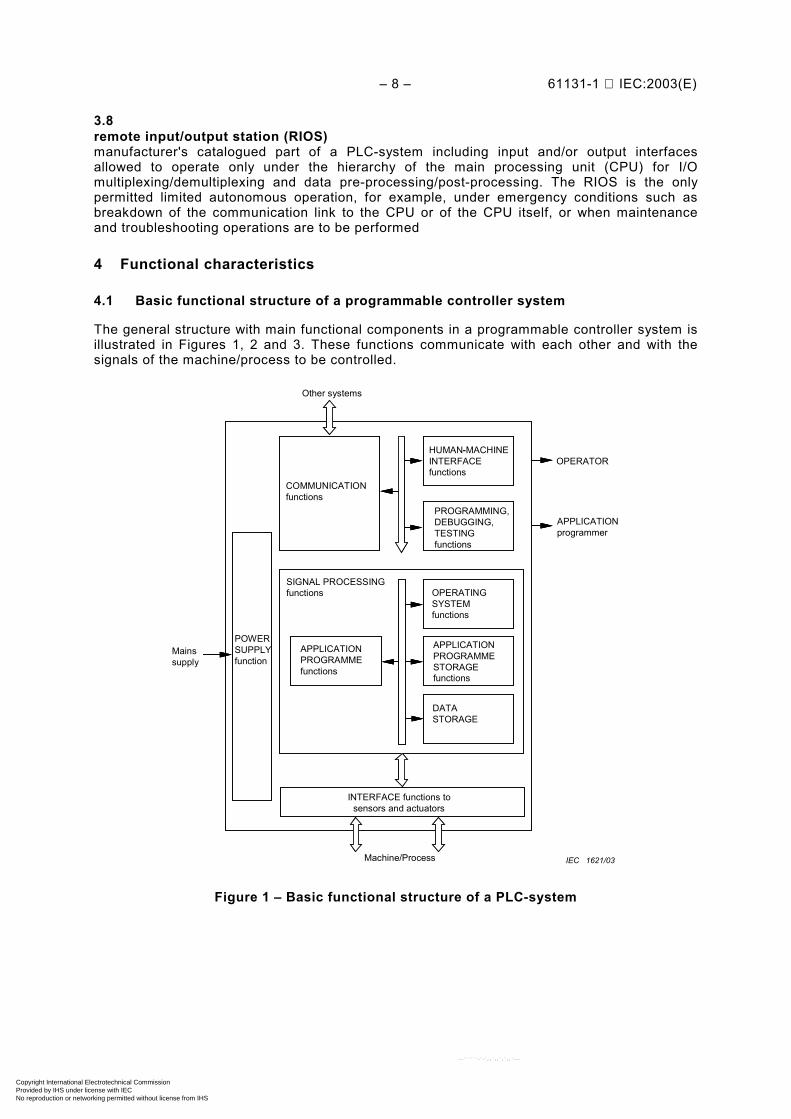
4.1 Basic functional structure of a programmable controller system
The general structure with main functional components in a programmable controller system isillustrated in Figures 1, 2 and 3. These functions communicate with each other and with thesignals of the machine/process to be controlled.
POWERSUPPLYfunction
Mainssupply
Other systems
INTERFACE functions tosensors and actuators
Machine/Process
APPLICATIONprogrammer
OPERATOR
COMMUNICATIONfunctions
PROGRAMMING,DEBUGGING,TESTINGfunctions
HUMAN-MACHINEINTERFACEfunctions
DATASTORAGE
APPLICATIONPROGRAMMESTORAGEfunctions
OPERATINGSYSTEMfunctions
APPLICATIONPROGRAMMEfunctions
SIGNAL PROCESSINGfunctions
-
IEC 1621/03
Figure 1 – Basic functional structure of a PLC-system
Copyright International Electrotechnical Commission Provided by IHS under license with IEC
Not for ResaleNo reproduction or networking permitted without license from IHS
--``````-`-`,,`,,`,`,,`---

61131-1 IEC:2003(E) – 9 –
Memory (ies)and
processing unit(s)
Input module(s)
Output module(s)
Communication module(s)
Power supply unit(s)
Main processing unit
Remote I/O station(s)
Peripherals
Implementer-specific subsystem(s)
IEC 1622/03
Figure 2 – Programmable controller hardware model(from IEC 61131-5)
Copyright International Electrotechnical Commission Provided by IHS under license with IEC
Not for ResaleNo reproduction or networking permitted without license from IHS
--``````-`-`,,`,,`,`,,`---
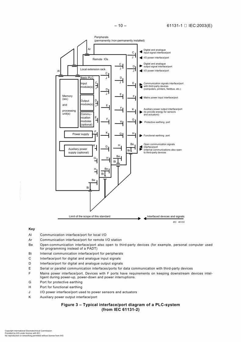
– 10 – 61131-1 IEC:2003(E)
Limit of the scope of this standard Interfaced devices and signals
Open communication signalsinterface/port(internal communications also opento third-party devices
BeHK G
Bi
Be
Be
Be
Bi
Bi
Bi
G H
H
Auxiliary powersupply (optional)
Protective earthing port
Peripherals(permanently /non-permanently installed)
Mains power input interface/port
Digital and analogueinput signal interface/port
I/O power interface/port
I/O power interface/port
Digital and analogueoutput signal interface/port
Communication signals interface/portwith third-party devices(computers, printers, fieldbus, etc.)
Auxiliary power output interface/port(to provide energy for sensorsand actuators)
Inputmodule(s)
Commu-nicationmodules(optional)
Memory(ies)
and
processingunit(s)
Power supply
Local extension rack
Basic PLC
Remote IOs
Outputmodule(s)
Al
Ar
C
C
C
C
G
G H
F
F
F
F
E
E
E
E
D
D
D
D
K
K
K
J
J
J
J
J
J
J
J
Functional earthing port
IEC 461/03
Key
Al Communication interface/port for local I/OAr Communication interface/port for remote I/O stationBe Open-communication interface/port also open to third-party devices (for example, personal computer used
for programming instead of a PADT)Bi Internal communication interface/port for peripheralsC Interface/port for digital and analogue input signalsD Interface/port for digital and analogue output signalsE Serial or parallel communication interfaces/ports for data communication with third-party devicesF Mains power interface/port. Devices with F ports have requirements on keeping downstream devices intel-
ligent during power-up, power-down and power interruptions.G Port for protective earthingH Port for functional earthingJ I/O power interface/port used to power sensors and actuatorsK Auxiliary power output interface/port
Figure 3 – Typical interface/port diagram of a PLC-system(from IEC 61131-2)
Copyright International Electrotechnical Commission Provided by IHS under license with IEC
Not for ResaleNo reproduction or networking permitted without license from IHS
--``````-`-`,,`,,`,`,,`---
61131-1 IEC:2003(E) – 11 –
The CPU function consists of the application programme storage, the data storage, theoperating system, and the execution of the application programme functions.
The CPU processes signals obtained from sensors as well as internal data storage andgenerates signals to actuators as well as internal data storage in accordance with theapplication programme.
• Interface function to sensors and actuatorsThe interface function to sensors and actuators converts– the input signals and/or data obtained from the machine/process to appropriate signal
levels for processing;– the output signals and/or data from the signal processing function to appropriate signal
levels to drive actuators and/or displays.The input/output signals to the interface functions may be coming from special moduleswhich pre-process external sensor signals according to the defined functions contained inthe special modules themselves. Examples of such special modules include PID module,fuzzy-control module, high-speed counter module, motion modules and others.
• Communication functionThe communication function provides data exchange with other systems (third-partydevices) such as other PLC-systems, robot controllers, computers, etc.
• Human-machine interface (HMI) functionThe HMI function provides for interaction between the operator, the signal processingfunction and the machine/process.
• Programming, debugging, testing and documentation functionsThese functions provide for application programme generation and loading, monitoring,testing and debugging as well as for application programme documentation and archiving.
• Power-supply functionsThe power-supply functions provide for the conversion and isolation of the PLC-systempower from the mains supply.
4.2 Characteristics of the CPU function
4.2.1 Summary
The capabilities of the programmable controllers are determined by programmable functionswhich are summarized in Table 1. They are subdivided for ease of use into application-orientedgroups.
Copyright International Electrotechnical Commission Provided by IHS under license with IEC
Not for ResaleNo reproduction or networking permitted without license from IHS
--``````-`-`,,`,,`,`,,`---

– 12 – 61131-1 IEC:2003(E)
Table 1 – Summary of programmable functions
Function group Examples
Logic control– Logic– Timers– Counters
Programming language elementsAND, OR, NOT, XOR, bi-stable elementsOn-delay, off-delayUp- and/or down-counting (of pulses)
Signal/data processing– Mathematical functions
– Data handling– Analogue data processing
Basic arithmetic: ADD, SUB, MUL, DIVExtended arithmetic: SQRT, trigonometric functionsComparisons: greater, smaller, equalSelecting, formatting, movingPID, integration, filtering (not as standard elements)Fuzzy control
Interfacing functions– Input/output– Other systems– HMI– Printers– Mass memory
Analogue, digital I/O modulesBCD conversionCommunication protocolsDisplay, commandsMessages, reportsLogging
Execution control Periodic, event-driven execution
System configuration Status checking (not as standard elements)
4.2.2 Operating systemThe operating system function is responsible for the management of internal PLC-systeminterdependent functions (configuration control, diagnostics, memory management, applicationprogramme execution management, communication with peripherals and with the interfacefunctions to sensors and actuators, etc.).After a power-down or a distortion, the PLC system can restart in three different ways.a) Cold restart
Restart of the PLC-system and its application programme after all dynamic data (variablessuch as I/O image, internal registers, timers, counters, etc., and programme contexts) arereset to a predetermined state. A cold restart may be automatic (for example, after a powerfailure, a loss of information in the dynamic portion(s) of the memory(ies), etc.) or manual(for example, push-button reset, etc.).
b) Warm restartRestart after a power failure with a user-programmed predetermined set of remnant dataand a system predetermined application programme context. A warm restart is identified bya status flag or equivalent means made available to the application programme indicatingthat the power failure shut-down of the PLC-system was detected in the run mode.
c) Hot restartRestart after power failure that occurs within the process-dependent maximum time allowedfor the PLC-system to recover as if there had been no power failure.All I/O information and other dynamic data as well as the application programme contextare restored or unchanged.Hot-restart capability requires a separately powered real-time clock or timer to determineelapsed time since the power failure was detected and a user-accessible means toprogramme the process-dependent maximum time allowed.
Copyright International Electrotechnical Commission Provided by IHS under license with IEC
Not for ResaleNo reproduction or networking permitted without license from IHS
--``````-`-`,,`,,`,`,,`---

61131-1 IEC:2003(E) – 13 –
4.2.3 Memory for application data storage• Application programme storage
The application programme storage provides for memory locations to store a series of in-structions whose periodic or event-driven execution determines the progression of themachine or the process. The application programme storage may also provide for memorylocations to store initial values for application programme data.
• Application data storageThe application data storage provides for memory locations to store I/O image tableand data (for example, set values for timers, counters, alarm conditions, parameters andrecipes for the machine or the process) required during the execution of the applicationprogramme.
• Memory type, memory capacity, memory utilizationVarious types of memory are in use: read/write (RAM), read-only (ROM), programmableread-only (PROM), reprogrammable read-only (EPROM/UV-PROM, EEPROM). Memoryretention at power failure is achieved by a proper selection of the memory type whereapplicable (for example, EPROM, EEPROM) or the use of memory back-up for volatilememories (for example, a battery).Memory capacity relates to the number of memory locations in Kbytes, which are reservedto store both the application programme and the application data. Memory capacitymeasurements are:– capacity in the minimum useful configuration;– size(s) for expansion increments;– capacity(ies) at maximal configuration(s).Each programmable function used by the application programme occupies memorylocations. The number of locations required generally depends on the programmablefunctions and the type of programmable controller.Application data storage requires memory capacity depending on the amount and format ofdata stored.
4.2.4 Execution of the application programme
An application programme may consist of a number of tasks. The execution of each task isaccomplished sequentially, one programmable function at a time until the end of the task. Theinitiation of a task, periodically or upon the detection of an event (interrupt condition), is underthe control of the operating system.
4.3 Characteristics of the interface function to sensors and actuators
a) Types of input/output signalsStatus information and data from the machine/process are conveyed to the I/O system ofthe programmable controller by binary, digital, incremental or analogue signals. Conversely,decisions and results determined by the processing function are conveyed to themachine/process by use of appropriate binary, digital, incremental or analogue signals.The large variety of sensors and actuators used requires accommodating a wide range ofinput and output signals.
b) Characteristics of the input/output systemVarious methods of signal processing, conversion and isolation are used in input/outputsystems. The behaviour and performance of the PLC-system depend on the static/dynamicevaluation of the signal (detection of events), storing/non-storing procedures, opto-isolation,etc.
Copyright International Electrotechnical Commission Provided by IHS under license with IEC
Not for ResaleNo reproduction or networking permitted without license from IHS
--``````-`-`,,`,,`,`,,`---
– 14 – 61131-1 IEC:2003(E)
Input/output systems in general display a modular functionality which allows for con-figuration of the PLC-system according to the needs of the machine/process and also forlater expansion (up to the maximum configuration).The input/output system may be located in close proximity to the signal processing functionor may be mounted close to the sensors or actuators of the machine/process, remotelyfrom the signal-processing function.
4.4 Characteristics of the communication function
The communication function represents the communication aspects of a programmablecontroller. It serves the programme and data exchange between the programmable controllerand external devices or other programmable controllers or any devices in an automatedsystem.
It provides functions such as device verification, data acquisition, alarm reporting, programmeexecution, and I/O control, application programme transfer, and connection management to thesignal-processing unit of the PLC from or to an external device.
The communication function is generally accomplished by serial data transmission over localarea networks or point-to-point links.
4.5 Characteristics of the human-machine interface (HMI) function
The HMI function has two purposes.
• To provide the operator with the information necessary for monitoring the operation of themachine/process.
• To allow the operator to interact with the PLC-system and its application programme inorder to make decisions and adjustments beyond their individual user scope.
4.6 Characteristics of the programming, debugging,monitoring, testing and documentation functions
4.6.1 Summary
These functions are implemented as either an integral or an independent part ofa programmable controller and provide for code generation and storage of the applicationprogramme and application data in the programmable controller memory(ies) as well asretrieving such programmes and data from memory(ies).
4.6.2 Language
For the programming of the application, there is a set of languages defined in IEC 61131-3.
a) Textual languages1) Instruction list (IL) language
A textual programming language using instructions for representing the applicationprogramme for a PLC-system.
2) Structured text (ST) language A textual programming language using assignment, sub-programme control, selectionand iteration statements to represent the application programme for a PLC-system.
b) Graphical languages1) Function block diagram (FBD) language
A graphical programming language using function block diagrams for representing theapplication programme for a PLC-system.
Copyright International Electrotechnical Commission Provided by IHS under license with IEC
Not for ResaleNo reproduction or networking permitted without license from IHS
--``````-`-`,,`,,`,`,,`---

61131-1 IEC:2003(E) – 15 –
2) Ladder diagram (LD) language A graphical programming language using ladder diagrams for representing theapplication programme for a PLC-system
3) Sequential function chart (SFC)A graphical and textual notation for the use of steps and transitions to represent the structure ofa program organization unit (program or function block) for a PLC-System. The transitionconditions and the step action can be represented in a subset of the above-listedlanguages.
4.6.3 Writing the application programme
• Generating the application programmeThe application programme may be entered via alphanumeric or symbolic keyboards and,when menu-driven displays are, or a graphical programme entry is, used via cursor keys,joystick, mouse, etc. All programme and data entries are generally checked for validity andinternal consistency in such a way that the entry of incorrect programmes and data isminimized.
• Displaying the application programmeDuring application programme generation, all instructions are displayed immediately, state-ment by statement or segment by segment (in the case of a monitor or other large display).In addition, the complete programme can generally be printed. If alternative representationof programming language elements is available, then the display representation is generallyuser-selectable.
4.6.4 Automated system start-upa) Loading the application programme
The generated programme resides either in the memory of the programmable controller orin the memory of the PADT. The latter requires a programme transfer via down-load ormemory cartridge insertion into the programmable controller before start-up.
c) Accessing the memory During start-up or trouble-shooting operations, the application programme and applicationdata storage are accessed by the PADT as well as by the processing unit to allowprogramme monitoring, modification and correction. This may be done on line (i.e. while thePLC-system is controlling the machine/process).
d) Adapting the programmable controller system Typical functions for adapting the PLC-system to the machine/process to be controlled are:1) test functions which check the sensors and actuators connected to the PLC-systems
(for example, forcing the outputs of the PLC-system);1) test functions which check the operation of the programme sequence (for example,
setting of flags and forcing the inputs);2) setting or resetting of variables (for example, timers, counters, etc.).
e) Indicating the automated system statusThe ability to provide information about the machine/process and the internal status ofthe PLC-system and of its application programme facilitates the start-up and debuggingof a PLC application. Typical means are:1) status indication for inputs/outputs;3) indication/recording of status changes of external signals and internal data;4) scan time/execution times monitoring;5) real-time visualization of programme execution and data processing;6) fuse/short-circuit protection status indicators.
Copyright International Electrotechnical Commission Provided by IHS under license with IEC
Not for ResaleNo reproduction or networking permitted without license from IHS
--``````-`-`,,`,,`,`,,`---
– 16 – 61131-1 IEC:2003(E)
f) Testing the application programmeTest functions support the user during writing, debugging and checking the applicationprogramme. Typical test functions are:1) checking the status of inputs/outputs, internal functions (timers, counters);2) checking programme sequences, for example, step-by-step operations, variations of
programme cycle time, halt commands;3) simulation of interface functions, for example, forcing of I/Os, of information exchanged
between tasks or modules internal to the PLC-system.g) Modifying the application programme
Functions for modification provide for changing, adjusting and correcting applicationprogrammes. Typical functions are search, replace, insert, delete, and add; they apply tocharacters, instructions, programme modules, etc.
4.6.5 Documentation
A documentation package should be provided to fully describe the PLC-system and theapplication. The documentation package may consist of
a) description of the hardware configuration with project-dependent notations;b) application programme documentation consisting of
1) programme listing, with possibly mnemonics for signals and data processed;2) cross-reference tables for all data processed (I/Os, internal functions such as internal
stored data, timers, counters, etc.);3) comments;4) description of modifications;5) maintenance manual.
4.6.6 Application programme archiving
For rapid repair and to minimize down-time, the user may want to store the applicationprogramme in non-volatile media such as flash, PC-cards, EEPROM, EPROM, disks, etc. Sucha record needs to be updated after every programme modification so that the programmeexecuting in the PLC-system and the archived programme remain the same.
4.7 Characteristics of the power-supply functions
The power-supply functions generate voltages necessary to operate the PLC-system andgenerally also provide control signals for proper ON/OFF synchronization of the equipment.Various power supplies may be available depending on supply voltages, power consumption,parallel connection, requirements for uninterruptible operation, etc.
5 Availability and reliability
Every automated system requires a certain level of availability and reliability of its controlsystem. It is the user's responsibility to ensure that the architecture of the overall automatedsystem, the characteristics of the PLC-system and its application programme will jointly satisfythe intended application requirements.
a) Architecture of the automated systemTechniques such as redundancy, fault tolerance and automatic error checking, as well asmachine/process diagnostic functions can provide enhancements in the area of availabilityof the automated system.
Copyright International Electrotechnical Commission Provided by IHS under license with IEC
Not for ResaleNo reproduction or networking permitted without license from IHS
--``````-`-`,,`,,`,`,,`---

61131-1 IEC:2003(E) – 17 –
b) Architecture of the programmable controller systemA modular construction in conjunction with suitable internal self-tests allowing rapid faultidentification may provide enhancements in the area of maintainability of the PLC-systemand therefore of the availability of the automated system. Techniques such as redundancyand fault tolerance may also be considered for special applications.
c) Design, testing and maintenance of the application programmeThe application programme is a key component of the overall automated system. Mostprogrammable controllers provide enough computing power to permit implementationof diagnostic functions in addition to the minimum control function. Machine/processbehaviour modelling and subsequent identification of faulty conditions should beconsidered.Adequate testing of the application programme is mandatory. Every modification impliesproper design and testing so that the overall availability and reliability are not impaired. Theprogramme documentation shall be maintained and annotated accordingly.
d) Installation and service conditionsPLC-systems are typically of rugged design and intended for general-purpose service.However, as for any equipment, the more stressing the service conditions, the worse is thereliability, and benefit in this area may be expected when permitted service conditions arebetter than the normal service conditions specified in IEC 61131-2. Some applicationsmay require consideration of special packaging, cooling, electrical noise protection, etc., forreliable operation.
Copyright International Electrotechnical Commission Provided by IHS under license with IEC
Not for ResaleNo reproduction or networking permitted without license from IHS
--``````-`-`,,`,,`,`,,`---

– 18 – 61131-1 IEC:2003(E)
Bibliography
IEC 60050-351:1998, International Electrotechnical Vocabulary (IEV) – Part 351: Automaticcontrol
______________
Copyright International Electrotechnical Commission Provided by IHS under license with IEC
Not for ResaleNo reproduction or networking permitted without license from IHS
--``````-`-`,,`,,`,`,,`---
Standards Survey
The IEC would like to offer you the best quality standards possible. To make sure that wecontinue to meet your needs, your feedback is essential. Would you please take a minuteto answer the questions overleaf and fax them to us at +41 22 919 03 00 or mail them tothe address below. Thank you!
Customer Service Centre (CSC)
International Electrotechnical Commission3, rue de Varembé1211 Genève 20Switzerland
or
Fax to: IEC/CSC at +41 22 919 03 00
Thank you for your contribution to the standards-making process.
Non affrancareNo stamp required
Nicht frankierenNe pas affranchir
A Prioritaire
RÉPONSE PAYÉE
SUISSE
Customer Service Centre (CSC)International Electrotechnical Commission3, rue de Varembé1211 GENEVA 20Switzerland
Copyright International Electrotechnical Commission Provided by IHS under license with IEC
Not for ResaleNo reproduction or networking permitted without license from IHS
--``````-`-`,,`,,`,`,,`---

Q1 Please report on ONE STANDARD andONE STANDARD ONLY . Enter the exactnumber of the standard: (e.g. 60601-1-1)
.............................................................
Q2 Please tell us in what capacity(ies) youbought the standard (tick all that apply).I am the/a:
purchasing agent R
librarian R
researcher R
design engineer R
safety engineer R
testing engineer R
marketing specialist R
other.....................................................
Q3 I work for/in/as a:(tick all that apply)
manufacturing R
consultant R
government R
test/certification facility R
public utility R
education R
military R
other.....................................................
Q4 This standard will be used for:(tick all that apply)
general reference R
product research R
product design/development R
specifications R
tenders R
quality assessment R
certification R
technical documentation R
thesis R
manufacturing R
other.....................................................
Q5 This standard meets my needs:(tick one)
not at all R
nearly R
fairly well R
exactly R
Q6 If you ticked NOT AT ALL in Question 5the reason is: (tick all that apply)
standard is out of date R
standard is incomplete R
standard is too academic R
standard is too superficial R
title is misleading R
I made the wrong choice R
other ....................................................
Q7 Please assess the standard in thefollowing categories, usingthe numbers:(1) unacceptable,(2) below average,(3) average,(4) above average,(5) exceptional,(6) not applicable
timeliness .............................................quality of writing....................................technical contents.................................logic of arrangement of contents ..........tables, charts, graphs, figures ...............other ....................................................
Q8 I read/use the: (tick one)
French text only R
English text only R
both English and French texts R
Q9 Please share any comment on anyaspect of the IEC that you would likeus to know:
............................................................
............................................................
............................................................
............................................................
............................................................
............................................................
............................................................
............................................................
............................................................
............................................................
............................................................
............................................................
Copyright International Electrotechnical Commission Provided by IHS under license with IEC
Not for ResaleNo reproduction or networking permitted without license from IHS
--``````-`-`,,`,,`,`,,`---

Copyright International Electrotechnical Commission Provided by IHS under license with IEC
Not for ResaleNo reproduction or networking permitted without license from IHS
--``````-`-`,,`,,`,`,,`---

ISBN 2-8318-7039-9
-:HSMINB=]\UX^\:ICS 25.040.40; 35.240.50
Typeset and printed by the IEC Central OfficeGENEVA, SWITZERLAND
Copyright International Electrotechnical Commission Provided by IHS under license with IEC
Not for ResaleNo reproduction or networking permitted without license from IHS
--``````-`-`,,`,,`,`,,`---