International Harvester CTS-11/12 R-Series Motor Truck...
60
---- a Ell REAR AXLE APPLICATION AND LUBRICATION CAPACITIES '" " " ;- II " :: !l - CODE 1401 1402 1403 1404 1405 1406 1409. 1410 1411 1412 1415 1416 l41S 1420 1423 IH MODEL ENGINEERING NUMBER HYD. AIR R-I060 R-1070 R-1170 R-1440 R-1470 R-1530 R-1531 R-1740 R-1741 R-2464 R-2467 R-25S5 R-25S6 R-1540 R-154l R-1640 R-164l R-27S0 R-27S1 R-1S10 R-lSll R-2800 R-2S01 (R-LINE TRUCKS) MANUFACTURER'S LUB. NUMBER DESCRIPTION TRUCK MODELS CAPACITY (PINTS) HYD. AIR IH Single Reduction R-II0 4 IH Single Reduction R-120, RM-120, RA-120 4 --_.- IH Single Reduction RA-140, R-150, 153, RM-150 5 2t [Tl IH Single Reduction R-160, 163, 165, RC-160 S S:' IH Single Reduction R-164, 170, 173, 175 a '0 R-174 Hydraulic, R-lS0, IH Single Reduction 11 R-lS3, lS5, lS53, RC-lS0 . " T-R-I00 T-R-I00 Single Reduction R-194, 200, 201, 202, 205 36 c: () E-13600 Eaton Two Speed R-160, 163, 165, RC-160" 13 ?\ tn E-13600 Eaton Two Speed R-164, 170, 173, 175 13 , R-174, Hydraulic, R-lS0, E-16600 E-16600 Eaton Two Speed 16 R-18.3, lS5, lS53, RC-lS0 @ E-2613 E-2614 Eaton Double Reduction R-lS4, 190, 193, 195 19 E-2695 E-2696 Eaton Double Reduction R-194, 200, 205 19 E-20500 E-20501 Eaton Two Speed R-190, 200 20 T-U-200P T-U -200P Timken Double Reduction R-210 3S T-U -300P T-U -300P Timken Two Speed R-210 37 CIl» t' I u III : ::! tz:1 (1)g» .... Donated by John & Susan Hansen - For Personal Use Only
Transcript of International Harvester CTS-11/12 R-Series Motor Truck...

----
a Ell ~ REAR AXLE APPLICATION AND LUBRICATION CAPACITIES ~ ~ shyII
~
l
~
~ -
CODE
1401
1402
1403
1404
1405
1406
1409
1410
1411
1412
1415
1416
l41S
1420
1423
IH MODEL ENGINEERING NUMBER
HYD AIR
R-I060
R-1070
R-1170
R-1440
R-1470
R-1530 R-1531
R-1740 R-1741
R-2464
R-2467
R-25S5 R-25S6
R-1540 R-154l
R-1640 R-164l
R-27S0 R-27S1
R-1S10 R-lSll
R-2800 R-2S01
(R- LINE TRUCKS)
MANUFACTURERS LUBNUMBER DESCRIPTION TRUCK MODELS CAPACITY
(PINTS)HYD AIR
IH Single Reduction R-II0 4
IH Single Reduction R-120 RM-120 RA-120 4 --_shy ~
IH Single Reduction RA-140 R-150 153 RM-150 5 2t [Tl
IH Single Reduction R-160 163 165 RC-160 S S
IH Single Reduction R-164 170 173 175 a 0
R-174 Hydraulic R-lS0IH Single Reduction 11 ~ R-lS3 lS5 lS53 RC-lS0
T-R-I00 T-R-I00 Single Reduction R-194 200 201 202 205 36 ~ c ()
E-13600 Eaton Two Speed R-160 163 165 RC-160 13 tnE-13600 Eaton Two Speed R-164 170 173 175 13
R-174 Hydraulic R-lS0 ~ E-16600 E-16600 Eaton Two Speed 16R-183 lS5 lS53 RC-lS0 E-2613 E-2614 Eaton Double Reduction R-lS4 190 193 195 19
E-2695 E-2696 Eaton Double Reduction R-194 200 205 19
E-20500 E-20501 Eaton Two Speed R-190 200 20
T-U-200P T-U -200P Timken Double Reduction R-210 3S
T-U -300P T-U -300P Timken Two Speed R-210 37 CIlraquo ~gtlt ~ t ~tz1
~n I u III ~
tz1(1)graquo rn~
Donated by John amp Susan Hansen - For Personal Use Only
REAR AXLE APPLICATION AND LUBRICATION CAPACITIES (R- LINE TRUCKS)
- Continued tI uqlPI tl gtlt ()Q~ ~ 0 L
tzJ
CODE
IH MODEL ENGINEERING NUMBER
HYD AIR
MANUFACTURERS NUMBER
HYD AIR
DESCRIPTION TRUCK MODELS LUB
CAPACITY (PINTS)
NOO o I
e~ tzJggtUI~
1425 R-2470 IH Two Speed With
Timken E300 Differential R-160 163 165 8
1426 R-2475 IH Two Speed With
Timken E300 Differential R-164 170 173 175 8
1428 RF-1475 E-22M IH Single Reduction RF-170 11 ea axle
~ 1429 RF-1575 E-22M Eaton Single Reduction RF-174 190 14 ea axle Z
1430 RF-1685 E-36M Eaton Single Reduction RF-194 210 20 Forward
21 Rear trl
3 1433 R-1l65 IH IH Single Reduction R-130 6 ~ 1435 R-2610 R-2611 TQ-301N TQ-301P Timken Two Speed R-194 200 205 32 ~ 1436 R-1547 R-1548 TL-101 TL-101 Timken Single Reduction R-190 193 195 23 3
c 1438 R-2995 R-2996 TL-301 TL-301 Timken Two Speed R-184 190 195 29 n
~ 1450 R-2795 R-2796 TR-300 TR-300 Timken Two Speed R-200 34 Ul
1451 RF-1690 E-36M Eaton Single Reduction RF-1942l0 20 Forward
21 Rear ~ ~ 1452 R-1470 IH IH Single Reduction R-164 170 173 175 8
1453 R-2466 E-13600 Eaton Two Speed R-164 170 173 175 11
1454 RF-1570 E-28M Eaton Single Reduction RF-174 190 14 ea axle
1455 R-2575 R-2576 E-17500 E-1750l Eaton Two Speed R-184 190 193 195 17
1456 R-2620 R-2621 E-18500 E-1850l Eaton Two Speed R-194 200 205 16
1457 R-2366 E-1350 Eaton Two Speed R-150 153 13
1458
1459
R-1572
R-1632
R-1573
R-1633
E-1790
E-1890
E-1791
E-1891
Eaton Single Reduction
Eaton Single Reduction
R-184 190 193 195
R-194 200 205
22
21 Ell
Donated by John amp Susan Hansen - For Personal Use Only
L-UNE MOTOR TRUCK SERVICE MANUAL
REAR AXLE GROUP
SPECIFICATlONS
Axle identification chart Specifications bull Wrench torque chart bull
SECTION A GENERAL INSTRUCTIONS FOR ALL HYPOID AXLES
Axle housing breather bullbullbullbullbull Axle shaft removal bull bull bull bull bull bull Cone center specifications bull bull bull bullbull Differential assembly (L-llO L-l20)bull bullbullbull Gear adjus tmen t for lash bullbull Gear tooth contact bullbull Hypoid rear axles bull bull bull bullbullbull Lubrication bullbull Pinion bearing adjustment bull Pinion setting bull bull bull bull Ring gear rivetsbullbullbullbullbull Single reduction axles - - sec tional views Straddle mounted pinion bearing bullbull
SECTION liB TWO-SPEED AXLE -- EATON
Des cription bull bull Lubrication bull bull bull Sectional view bull bull bull bull Servicing and disassembly bull
SECTION C DOUBLE-REDUCTION AXLE -- EATON
Description bull Differential lubricators bull bull Herringbone gear adjus trnent Herringbone gear shaft (cross-shaft) Hypoid pinion shaft and adjustment Sec tional view bull bull bull bull
SECTION D SINGLE-REDUCTION AXLE -- TIMKEN
Description bullbullbullbull Differential carrier bearing pre-load Differential disassembly Gear adjus tmen tbullbullbull Lubrication bullbull Pinion bearing pre-loadbull Sec tional view bull bull bull Thrus t block ins tallation
SECTION E DOUBLE-REDUCTION TWO-SPEED -- TIMKEN
Description bull Differential adjus trnent Electric two-speed shift Hypoid pinion and cage bull Lubrication Shift collar adjus tment
PRINTED iN UNITED STATES OF AMeRle
AXLE-REAR Index
Page 1
Page 1
2-5 6
9 8 9 I 2
10 5 6
1 1
9 10 6 7
2 3 4 7 8
11 12 7
2 3 1
2 3
2 3 2 2 2 1
Z 4
2 3 4 5 3 I 5
1 4 3
2 3 4 3
Donated by John amp Susan Hansen - For Personal Use Only
AXLE-REAR Index L-LINE MOTOR TRUCK SERVICE MANUAL Page 2
SECTION Fit
DOUBLE-REDUCTION -- TIMKEN Description bullbullbullbullbullbullbullbullbull Helical gear shaft (cross shaft) bull Hypoid pinion and cage bullbullbull Lubrication Oil seals bullbullbull bullbull
SECTION G TANDEM AXLES
Center cross bar and equalizing beam mounting Description Dipoundferential lockbullbullbullbullbullbullbullbullbullbullbullbullbull Disassembly of power divider (axle mounted) bull Equalizing beam ends bullbullbullbullbullbullbullbull Legends for sectional viewbullbullbullbullbull Sectional view (axle mounted power divider) bull Torque rod ends bull
SECTION H ELECTRIC SHIFT
Axle shift unit bullbullbull bullbull bullbull Axle unit disassembly bullbullbullbull Des cription bullbull bullbull Lubrication bullbullbullbullbullbull Par ts identification lis t bull Service and trouble-shooting Shifting ins tructions bull Speedometer adapter Wiring system bullbull
Page
I 3 3 3 2
4 I 2
34 4 5
2 I 5
2 3 4-7 1 2
4 8
34 7 2 2
Donated by John amp Susan Hansen - For Personal Use Only
------
-- ------------- ---
---- - ----
REAR AXLE IDENTIFICATION CHART
0 to 0 0 0 0 0 0 0Axle Axle 0
0
0 ~ 0
U) gt00 DESCRIPTION o~ 0 M 0 M ~ M~ 0 M~ U) COo M ~ 0 O~ tOO o U) No M N M to U) gt0 gt0 gt0 gt0 r- r-r- ~ co 0 0 ~ N NCode coco co ~~ 00 ON NN NMModel -~
~- - I NN N IN I
I I 1 1 I I NNIl 1 I 1 UI I Pt1 1 UI I I INwnber Nwnber U Pt I 1 IU ~ ~ I I Pt1 Pt 11 11 11I I I I I I I I 11 I 11 11 l 11 I I I I I I11 11 11 11
1401 __ R-1060 Single-ReduCtion-IHbullbull ~ - shy~-----~~ - ~~~
1402 R-I070 Single - Reduction-IH bull bull XX r - shy ~~ -
1403 R-1l70 ~gle-Recluction-IHo bullbull X X X X ~ t
1404__ amp-440 ~ Sinde-Reduction-IHbullbullbullbull X X XX z 1405 R-1470 SinKle-Reduction-IHbullbull X X X X [TJ
0 bull
- I-- shy0 bull1406 R-1530 Single-Reduction-IHbullbull X X X X X $1407 R-1555 Sin~-Reductio~n X XX X X
1408 R-1630 Single -ReducHon-Eaton bull -~- -
X X X ~ ~09 R-1741 SingE)~educ tion-Tirnken
l-I--- o1410 R-2465 Twlt~~ed-~a~on___~~~~~ XX XX
l-I-0
0 bullbullbull1411 R-2466 Two-Speed-Eaton bull X X X X- ~~ l- -1412 R-2585 Two-Seeed-Eaton bullbull 0 ~ X X X XX 01413 R-2580 ~~p~lti-E~ton bullbullbullbull X XX XX C 1414 R-2000- Two-Speed-Eaton bullbullbullbullbull X X X oI~~- --- f--I- shy1415 R-1540 Doub1e-Reduction-Eaton X XX A 1416 -- R-1640 DoulJ1e-Recl_~_Hltgtn-Eat01 X X X
f- - ---- -- --- I-~ UJ--- f f- 1-1417 ~~-
[TJ --~ ~~ i-- --- ---- shy
1418 0 ~~~- ~~
1419 R-1731 Douh1e-Reduction- lt Tirnken bullbullbullbullbullbullbull l- X X X n I~~~-
[TJ1420 R-1810 Doub1e-Reduction-~~
Tirnken XX0 bull 0 bull 0 bullbullbull 0 bull $ J1~L~_ R~1140 ~l1gle-ReductionTirnken t-I- raquo1422 R-2741 Two-Speed-Tirnken bullbullbullbull
-~
Xl- z1423 RZ800 ~Speed-Tirnken bullbullbull
t-~
X c1424-- ---- shy raquo
1425 R-2470 Two-Speed with Tirnken r Diff
~~~ t- shy10 l-I- i- shyR-2-75 TwoSpeed with Tirnken
~~- ~
i=-~ Difh_L~middot bull bull bull 0 0 ---- I- I1427 ~ RZ590- Two-Speed with Tirnken
Dirf 0 bullbull 0 bullbullbullbullbullbullbull
~gt1428 RF-1475 Single -Reduc tionIH _____bull X 1429 RFTs75 ~~ge~~dt1c~~on-IHbullbullbullbull X
~ -- P ~ I1430 RF-1685 ~_~gle-Reduction-~_~ton -
X tzlI- - C i-- i-- I~~~ ItJ () I1431
~~
-- III III )tJ1432 OQ po 11
-~ I-~ ---I- --Ishy ~ g gtshy1433 Rmiddot1l65 Single-Reduction-IHbull - X --- - UI )tJ
Donated by John amp Susan Hansen - For Personal Use Only
------
--- --- ---
--
REAR AXLE SPECIFICATIONS ---~-
REAR AXLE MODEL R-I060 R-I070 R-1165 R-1l70
Code bullbullbullbull 1401 1402 1433 1403
Type (Semi or Full-Floating)bull Semi Full Full Full
Pinion Mounting bull bull bull bull bull Straddled Straddled Straddled Straddled
Axle Shaft
Diameter at splines bullbullbull 1-932 1-93211 1-3364 1-3364
Number of splines bullbullbullbullbull 10 10 16 16
Pinion Cone Center (amount of variation marked on pinion) 2609 2609 2984 2984
Lubricant Capacity (Pints) bullbull 4 4 4 3
373Axle Ratios bullbullbullbullbullbull 41 488 488 41 4777 5571 557
513 6166 616
Pinion Adjus trnent Press pressure (tons) bull 10 10 10 10
Cage Rotating Torque Scale Reading (Lbs) bullbullbull 10-25 10-25 10-25 10-25
Pinion Nut Torque (Ft Lbs) bull 200-230 200-230 200-230 200-230
Differential Bearing Pre-load (Total)bullbullbullbullbullbullbull 00511 -007 bull005- 007 005 -00711 005-00711
--~
R-1440
1404
Full
Str-addled
1-34
16
3253
8
5285 6166 6666 7166
10
10-25
200-230
bull005 - 007 ~ ---- -- shy
R-1470
1405
Full
Straddled
1-3411
16
3253
8
6166 6666 7166
10
10-25
280-300
005 -00711
~--
RF-1475
Forward Rear RF-1476 RF-1477
1428 1428
Full Full
Overhung Straddled ---shy
1-3411 1-3411
16 16
4156 3253
8-Axle 8 3-PD
6166 6166 7166 7166
10 10
10-25 10-25
350-400 280-300
005 -007 00511-00711
tJUl)shy
~ gtlt root ~MN o I pgtlI pM0)shy~lI
r t z [Tl
o ~
d 0
--l 0 C () A (J) [Tl 0 lt () [Tl
raquo ~ z c raquo r
Pressure against bearing race when checking rotating torque of pinion cage
Donated by John amp Susan Hansen - For Personal Use Only
-------- -----
-----
----------
REAR AXLE SPECIFICATIONS
RF-1685RF-1575
REAR AXLE MODEL R-1530 R-1540 R-1555 Forward Rear RF-1576 RF-1577
Code bullbullbullbullbullbullbullbullbullbull 1406 1415 1407 1429 1429
Type (Semi or Full-Floating)bull Full Full Full Full Full
Pinion Mounting bull bull bull bull bull bull bull Straddled Overhung Straddled Overhung Straddled
Axle Shaft
Diameter at splines bullbullbull 1-78f 1-636411 1-636411 1-3411 1-341
Number of splines bullbull 16 16 16 16 16
Pinion Cone Center (amount of variation marked on pinion) 3472 2500 3844 4656 3473
Lubricant Capacity (Pints) bull II 19 20 12-Axle 3-PD
12
Axle Ratios bullbullbullbullbullbullbullbullbullbull 5571 7049 5571 6166 6166 65 7754 65 7166 7166
7166 9025 7166
Pinion Adjus trnent Press pressure (tons) bullbull 10 10 10 10 10
Cage Rotating Torque Scale Reading (Lbs) bullbullbullbullbull 10-25 10-25 10-25 10-25 10-25
Pinion Nut Torque bullbullbullbullbullbullbull 280-300 280-300 350-400 350-400 280-300
Differential Bearing Pre-load (Total)bullbullbullbullbullbullbullbullbull 005 - 007 005 -007 005 -007 005-007 005 -007
Pressure against bearing race when checking rotating torque of pinion cage
Forward RF-1686
-
1430
Full
Overhung
2-1811
16
4875
20-Axle 3-PD
5756 6940
10
10-25
600-900
bull005 - 007
Rear RF-1687
1430
Full
Overhung
2-18
16
4875
21
5756 6940
10
10-25
400-500
005 -007
R-1630
1408
Full
Straddled
2-18
16
2937
18
5571 65
7166
10
10-25
350-400
bull005 -007
~ r Z [l1
$ o -1 o 0
-1 0 C () A fJ) [l1 0 lt n [l1
$ raquo z c raquo r
en Utl gt ~~ (l)t Iraquo~middotM
III I p~oMsgt (f)~
Donated by John amp Susan Hansen - For Personal Use Only
- --- --
tI CIl gtREAR AXLE SPECIFICATIONS Jg ~ ~ -- --- -- ~ n t
~SMREAR AXLE MODEL R-1640 R-1730 R-1731 R-1740 R-1810 R-2465 R-2466 R-2470 n I
1lllt1 g~
Code bullbullbullbullbullbullbullbull 1416 1419 1421 1420 1410 1411 1425bull bull bull D ~ lt1 -
Type (Semi or Full-Floating) Full Full Full Full Full Full Full Full
Pinion Mounting bullbullbullbullbullbull Overhung Overhung Overhung Straddled Overhung Overhung Overhung Overhung
r Axle Shaft r
zDiameter at splines bullbullbull 2-1811 2-3811 2-38 11 2-3811 2-3811 1-34 1-34 1-3411 [TJ
$ Number of splines bullbullbull 16 16 16 16 16 16 16 16 o
-l Pinion Cone Centers (amount of o
0variation marked on pinion) 2625 4281 4281 j
Lubricant Capacity (Pints) bullbull 19 38 38 36 38 13 13 C ()
AAxle Ratios bullbullbullbullbullbullbullbullbullbull 7049 591 591 528 591 514-715 5l4-7l5 613-810 tn7754 651 651 683 651 583-811 583-811 670-886
9436 779 779 741 721 633-881 633-881 ~ 869 869 779 lt976 976 976 ()
[TJ
Pinion Adjus tment $ Press pressure (tons) bullbullbull 10 10 10 10 10 10 10 raquo z
cCage Rotating Torque Scale raquoReading (Lbs) bullbullbullbullbull 10-25 4-5 amp 4-5 amp 4-5 amp 4-5 amp 10-25 10-25 r
Pinion Nut Torque (Ft Lbs) bullbull 400-500 700-900 700-900 700-900 700-900 280-300 280-300
Differential Bearing Pre-load (Total)bullbullbullbullbull 005-007 See Note See Note See Note See Note bull005 -007 bull005 - 007
Pressure against bearing race when checking rotating torque of pinion cage amp Tirnken Axle NOTE Tighten one notch each from 000 end play
Donated by John amp Susan Hansen - For Personal Use Only
---
-----
-- ----
---
---
---
----
-----
---
-----
REAR AXLE SPECIFICATIONS
REAR AXLE MODEL R-2475 R-2580 R-2585 R-2590 R-2600 R-2740 R-2741 R-2800
Code 1426 1413 1412 1427 1414 1422 1423
Type (Semi or Full-Floating)bull Full Full Full Full Full Full Full Full
Pinion Mounting bullbullbull Overhung Overhung Overhung Overhung Overhung Overhung Overhung Overhung ~ C zAxle Shaft I [l1
Diameter at splines bullbull 1-3411 1-636411 1-7811 1-7811 2-1811 2-3811 2-3811 2-3811 3 o --l
Number of splines bullbullbullbullbull 16 16 16 16 16 16 16 16 o ----- 0
Pinion Cone Centers (amount of --l 0variation marked on pinion) 5281 4B12 5281 C ()
Lubricant Capacity (Pints) bullbullbull 22 20 22 37 37 37 ~
---- fJ) [l1
Axle Ratios bullbullbullbullbullbullbull 613-BI0 5571-7594 5571-7749 595-730 5571-7594 493-591 493-5lt1 493-591 0 670-886 65-BB66 6166-8577 613-B15 6500-8866 642-838 642-838 642-838 lt65-9041 666-885 699-838 699-838 699-838 n
[l1
Pinion Adjus trnen t 3Press pressure (tons) bull 10 10 10 25 25 25 raquo z
cCage Rotating Torque Scale raquoReading (Lbs) bullbullbullbull 10-25 10-25 10-25 4-5 amp 4-5 amp 4-5 amp r ~--
Pinion Nut Torque (Ft Lbs) bull 350-400 280-300 350-400 BOO-IIOO 800-1100 800-1100
Differential Bearing Pre-load (Total)bullbullbullbullbullbullbullbull 005 -007 005-007 005 -007 See Note See Note See Note ggtgtshy
t1I gtlt81 tM
U () I Pressure agains t bearing race when checking rotating torque of pinion cage Pl~~ OQ M
amp Tirnken Axle (I) g gtshyNOTE Tighten one notch each from 000 end play J1Ul~
Donated by John amp Susan Hansen - For Personal Use Only
AXLE-REAR Specifica tions Page 6
Socket
FT LBS WRENCH TORQUE A
1 foot200 2 feet
1-12 feet250 2 feet
1-IZ feet 300 Z feet
3 feet
2 feet 2-12 feet
350 3 feet 3-12 feet
2-12 feet 3 feet450 3-12 feet 4 feet
3 feet 3-12 feet500 4 feet 4-12 feet
3-12 feet 4 feet550 4-12 feet 5 fee t
4 feet 4-12 feet600 5 feet
15-12 feet I
Wrench Torque Chart
L-LlNE MOTOR TRUCK SERVICE MANUAL
B
Handle A-22879
EFFORT ON WRENCH (APPROX)
B
200 Ibs 1001bs
170 Ibs 125 Ibs
200 Ibs 150 1bs 100 1bs
175 1bs 140 Ibs 118 1bs 100 1bs
180 Ibs 150 1bs 129 1bs 113 1bs
167 Ibs 1441bs 1Z5 lbs 112 1bs
158 1bs 1371bs 123 1bs 110 Ibs
1501bs 1341bs 1Z0 Ibs 110 1bs
The above chart illustrates the length of the wrench handle (A) and the effort that must be applied at (B) when tightening to secure the indicated torque
Donated by John amp Susan Hansen - For Personal Use Only
AXLE-REAR Section AL-L1NE MOTOR TRUCK SERVICE MANUAL
Page I
AXLES-REAR
GENERAL INSTRUCTIONS FOR ALL HYPOID AXLES
HYPOID REAR AXLES (ALL MODELS)
All rear axles have a hypoid ring gear and pinion whether single reduction double-Teducshytion double-reduction (single and two-speed final drive) and two-speed differential Hypoid gears have a greater inherent torque capacity due largely to the fact that the hypoid pinion is much larger in diameter and the pinion teeth are correspondingly larger than those found in a spiral bevel pinion for the same number of teeth and the same diameter ring gear
The hypoid pinion has a longer face because of its offset location It also has larger tooth surface areas and usually has more teeth in ins tant contact with the gear It is thes e design characteristics which contribute to greater strength and quieter final drive operation Beshycause of this greater tooth contact it is more difficult to secure correct pinion setting at time of overhaul or when replacing differential bearings and every effort must be made to be sure the final setting results in best possible tooth contact
Note that the pmlOn center line (E F) is offset from the ring gear center line (C D)
~~-----------D
F
pinion
A-2282B
Fig I - Illustration shows location of pinion in relation to center 1 ine of ring gear Center line of pinion is below center line of ring gear
NOTE When adding to or replacing lushybricant in a rear axle having hypoid gears use only hypoid lubricants (See under Lubricashytion on page 9)
REAR AXLE HYPOID GEAR REPLACEMENT AND ADJUSTMENT
Hypoid Gear Tooth Contact (All Models)
The proper adjustment of hypoid gears in assembly is a vital factor in obtaining quiet and durable gears and the same methods of adjustshyment applies to both straight spiral bevel and to hypoid type gears
There are two distinct considerations in obtaining the proper tooth contact cone center and backlash
Hypoid as well as bevel and spur gears are cut with a predetermined amount of backlash The backlash usually varies from 004 to 005 on small gears and increases on large gears Generally the gears are machined to run flush with each other at the outer end (heel or large end) of the tooth and gears should be set according to their theoretical cone center (Figs 2 3 and 4)
Cone Center Specifications
Matched and mated hypoid ring gears and hypoid pinion gears are furnished both for service and for production
Mated gears are marked with figures showing the amount of variation from their theoretical cone center
Tbeoretical cone center of _ bevel drive gear and pinion
~~~Ii--Ilt-~ ~ ~
I i
Fig 2
Fig 2 illustrates a hypoid ring gear and pinion adjusted to theoretical cone center wherein the cone centers of both gears coincide The specifications in this case would be the distance from the line (A B) (Fig 1) drawn through the center of the hypoid ring gear to the ground face of the hypoid pinion on center line (E F) On some axles the pinion is loshycated above the center line (C D) (Fig 1) In these cases the term hypoid still applies
PRINTED IN UNITED STATES OF EAtCA
A-22797
Donated by John amp Susan Hansen - For Personal Use Only
AXLE-REAR Section A L-UNE MOTOR TRUCK SERVICE MANUAL Page 2
center of pinion Bracket screw
Fig 3
Fig 3 illustrates a setting wherein the mating of the gears has necessitated the pinion cone center being farther than the ring gear center The pinion marking in this case will be minus (-) because the distance from the ring gear center is less
~M eo~_bd driv gw01 ~~- -
- i a A-22BOI
Fig ~
Fig 4 illustrates a condition where the mating of the gears required the pinion cone center to be farther OUT The pinion marking will be plus (+) because the distance is greater
SE-1065 Pinion Setting Gauge
The SE-I065 pinion setting gauge is a preshycision gauge designed for use in adjusting differentials to the proper cone setting of the ring gear and pinion It is used only in adjustshyment of matched sets of gears A step plate and bracket have been added to the set so that the gauge may be used on all hypoid differenshytials with satisfactory results NOTE Be sure to allow for thickness of the step plate 400 when making calculations (Fig 5)
The use of SE-I065 gauge makes possible the exact duplication of the setting etched on the pinion This results in the best possible setting with a minimum loss of time It is adshyvisable to check all pinion settings with a paint impression before considering the work comshyplete By so doing visible proof of the pinion gauge setting accuracy is obtained also long and quiet gear performance is assured
Adjustment of differentials is a simple matter with the SE-I065 gauge Briefly it is only necessary to
1 Install pinion and bearing assembly in differential carrier
A-22494
Fj g 5
Fig 5 shows SE-I065 tool equipment in position on hypoid differential case Make certain that the bearing bores are clean and free of nicks or burns The step plate must be placed on the pinion end so that the lugs in the step plate straddlt the bearing staking inshydentations on the smaller axles
2 Install step plate and bracket as shown in Fig 5 CAUTION Be sure lugs on step plate straddle the bearing staking indentashytions
3 Mount assembled SE-I065 gauge in bearing bores of carrier
4 Take micrometer reading to check point of pinion Add 40011 (thickness of step plate) to reading Write down reading
5 Locate specified cone center specification for particular model on chart Write down specified figures
6 Locate on pinion the etched marking which indicates variation from zero cone center If a minus figure subtract from specified cone center and if a plus figure add to specified cone center Results of calculashytion give corrected cone center
7 Comparison of corrected cone center (6) with actual measurement (4) indicates amount of change necessary for pinion position
8 Install ring gear and carrier in position
9 Adjust backlash according to marking on ring gear
(See following page)
Donated by John amp Susan Hansen - For Personal Use Only
AXLE-REAR Section AL-UNE MOTOR TRUCK SERVICE MANUAL
Page 3
Example of Mathematics involved
Truck model to be L-llO
(a) Micrometer reading (add 400 for step plate) bull 34400
(b) Specified cone center on chart bull 340011
(c) Pinion marked (-5) 005
(d) Subtraction (b-c) gives corrected cone center 3395
(e) Subtract corrected cone center (d) from actual measurement (a) bull 045
(f) It is necessary to move pinion INbull
(g) Remember -- It is essential to arrive at a measurement as nearly equal the corrected cone center as possible
(h) DO NOT FAIL TO VERIFY ACCURAshyCY OF THE ADJUSTMENT SECURED WITH THE SE-l065 gauge by checking the gear tooth contact using the paint impression method as set forth under General Rear Axle Hypoid Pinion and Ring Gear Adjustment which follows
GENERAL REAR AXLE HYPOID PINION AND RING GEAR ADJUSTMENTS
(PAINT IMPRESSION METHOD)
The following general instructions and suggestions are for the benefit of those service stations not equipped with an SE-l065 pinion setting gauge Bear in mind that the accuracy of the adjustment obtained with the following procedure is dependent upon the skill of the operator
Hypoid gears when mounted should show a bearing toward the toe or small end of the tooth never atthe heel or large end the reason being that it is practically impossible to make gears and gear mounting rigid enough so that there will not be some slight deflection when fullloadis applied This always has a tendency to caus e the bearing to come on the heel of the tooth and when gears are adjusted so that the bearing is toward the heel of the tooth it reshys ults in a concentration of load on the top corshyner of the heel and breakage will follow
Checking tooth contact is accomplished by means of oiled red lead applied lightly to the bevel gear teeth (Fig 6) When the pinion is rotated the red lead is squeezed away by the contact of the teeth leaving bare areas the exact size shape and location of the contacts
Fig 6
Fig 7
Sharper impressions may be obtained by applying a small amount of resistance to the gear with a flat steel bar and using a wrench to rotate the pinion When making adjustments check the drive side of the bevel gear teeth Coast side contact should be automatically corrected when drive side contact is correct As a rule coating about twelve teeth is suffi shycient for checking purposes
With adjustments properly made the correct tooth contact shown in Fig 7 will be secured The area of contact starts near the toe of the gear and extends about 80 permiddot cent of the tooth length This adjustment results in a quiet running gear and pinion set which because the load is distributed over the te eth within the proper area will deliver all the long service built into it
Figs 8 to 11 illustrate method of adjustshyment in securing the proper gear tooth contact
PRINTED IN UNITED STATES OF AMERICA
Donated by John amp Susan Hansen - For Personal Use Only
AXLE-REAR Section A L-UNE MOTOR TRUCK SERVICE MANUAL Page 4
A HIGH NARROW CONTACT IS NOT DESIRABLE If gears are allowed to operate with an adjustment of this kind noise galling and rolling over of the top edges of the teeth will result To obtain correct contact move pinion toward bevel gear to lower contact area to proper location This adjustment will decrease backlash between pinion and bevel gear teeth which may be corrected by moving bevel gear away from pinion Backlash of
006 to 012 is correct
Fig 8
A LOW NARROW CONTACT IS NOT
DESIRABLE If gears are allowed to opershy
ate with an adiustment of this kind galling
noise a nd grooving of teeth will result To
obtain correct contact move pinion away
from bevel gear to raise contact area to
proper location Correct backlash of 006
to 0l2f may be obtained by moving
bevel gear toward pinion
Fig 9
A-15848
A Conlac1 adjustmeuront
B Sack lash correction
Amiddot15847
A CONTACT
AOJUSTMfNT
B BACK LASH
CORRECTION
A SHORT TOE CONTACT IS NOT DEshy
SIRABLE If gears are allowed to operate
with an adiustment of this kind chipping
at tooth edges and excessive wear due to
small contact area will result To obtain
correct contact move bevel gear away
from pinion This will increase the lengthshy
wise contad and move contact toward heel
of tooth Correct backlash of 006 to 012
can be obtained by moving pinion toward
bevel gear
Fig 10
A SHORT HEEL CONTACT IS NOT DEshySIRABLE If gears are allowed to operate with an adiustment of this kind chipping excessive wear and noise will result bull To obtain correct contact move bevel gear toward pinion to increase the lengthwjse contact and move contact toward toe Corshyrect backlash of 006 to 012 can be obshytained by moving pinion away from bevel gear Several adiustments of both pinion and gear may be necessary before correct confact and backlash are secured
Fig I I
A CONTACT
4OJUSTMENT
B BACK lASH
CORRECTION
A CONTACT
ADJUSTMENT
B BACK LASH
CORRECTION
AmiddotJSBSO
A-15849
Donated by John amp Susan Hansen - For Personal Use Only
AXLE-REAR Section AL-L1NE MOTOR TRUCK SERVICE MANUAL
Page 5
Gear Adjustment for Lash
Generally if original gears are being reinshystalled red leading of teeth will not indicate the same contact as new gears and can be misshyleading Gears that have been in service for long periods form running contacts due to wear of teeth therefore the original shim pack should be maintained to check gear lash Gear lash when using original gears can be reduced only to a point of smooth rotation of gears
If the gear lash is in excess of maximum tolerance as stated under Gear Adjustment the lash may be reduced only in the amount that will avoid overlap of the worn tooth section (Fig 12) Rotate the gears and check for smooth or rough operation If a slight overlap as illustrated (Fig 12)takes place at the worn tooth section rotation will be rough
Worm section Pinion too deep in of ring gear ring gear
Ring gear Overlap
Correct Incorrect
A-19693
Fig 12
Fig 12 illustrates worn condition of gear teeth and overlapping condition
When installing new gears check gear lash with dial indicator (Fig 13) and adjust to obtain amount of backlash marked on ring gear as follows
1 Set pinion according to procedure outlined under SE-I065 Pinion Setting Gauge
2 To move ring gear tighten or loosen differential bearing adjusting nuts as reshyquired
3 After correct gear lash is secured check and adjus t as neces s ary to obtain the correct tooth contact (See Gear Adjustshyment for correct tooth contact)
PRINTED IN UNITED STATEs OF AMERICA
Fig 13 - Checking gear lash
Adjust Differential Bearing Pre-Load
Using dial indicators at side of each bearshying cap (Fig 14) adjust to obtain bearing preshyload as follows
1 Loosen adjusting nuts only enough to notice end play on indicators
2 Tighten adjusting nuts only enough to obtain 000 end play reading on indicators
Note While gear is held in 000 end play and before loading bearings check gear for runout If runout exceeds 008 reshymove differential and check for cause
Dial indicators
Fig I~ - Adjusting differential bearing preshyload
Donated by John amp Susan Hansen - For Personal Use Only
AXLE-REAR Section A L-UNE MOTOR TRUCK SERVICE MANUALPage 6
3 Tighten BOTH adjusting nuts from 000 end play to pre-load differential bearings Adjust pre-load to secure equal pre-load reading at indicators (See specifications for pre-load data on the various axles)
4 Tighten bearing cap stud nuts to specified torque
5 Install adjusting nut locks
Pinion Bearing Adjustment for Correct Pre-Load (Torque Method)
After the pInIon the pInIOn bearings and spacers have been assembled in the pinion bearing cage place the assembly in a press being sure to use a sleeve adapter as shown in Fig 15 Press the bearing down firmly and rotate the pinion cage to align the bearings and assure normal bearing contact Set press at correct pressure and attach a spring scale to pinion cage as indicated in Fig 15 Read scale only while pinion cage is turning If preload reading is incorrect thE7 bearing load may be increased by installing a thinner spacer ot decreased by using a thicker spacer
The correct press ram pressure and scale reading for the various axles may be found in the Rear Axle Specifications
Fig 15
Fig 15 shows method of checking pinion bearing preload using scales to measure torque
Pinion Bearing Adjustment for Pre-Load Using Dial Indicator (This method should only be used on the smaller axles)
An outside or bench assembly should be made of bevel pinion bearings and cage With cups assembled in cage assemble the pinion and inner bearing cone and roller assembly in place using the proper spacer to space the pinion bearings Next assemble the outer pinshyion bearing cone and rollers spacer companshyion flange washer and nut
Fig 16
Fig 16 shows method of attaching dial indicator when adjusting bearing pre-load This method can be used when press equipment is not available
NOTE Do not install pinion bearing oil seal until all adjustments have been completed Then check bearing fit to see that bearings have no end movement with flange nut drawn up tight To secure this fit proper spacer must be found by trial as follows
(I) Place assembly in vise in position shown (2) Mount indicator on propeller shaft flange
with indicator finger resting on upper face of cage (See A Fig 16)
(3) With the tips of the fingers grasp the bearshying retainer and work bearings up against the back face of pinion (See B Fig l6)
(4) With the bearings held firmly against the pinion move the cage up and down obshyserving the indicator reading It is imshypossible to accurately determine the end play unless the bearing is worked loose and up against the pmIon Assemblies having as much as 005 end play cannot be moved enough to show on the indicator until the bearing has been worked up and away from the cup
CAUTION
Bearings must be absolutely clean
Donated by John amp Susan Hansen - For Personal Use Only
AXLE-REAR Section AL-UNE MOTOR TRUCK SERVICE MANUAL
Page 7
Preload the pinon bearings by replacing the spacer between the pinon bearings with one smaller to the extent of the amount of the end play plus 002t for the loading For example should there be 005 end playas indicated in the sketch in the assembly replace the spacer with one 001 smaller Do not depend upon the spacers to be right according to number but check each and everyone with an accurate micrometer Before reassembling the bearshyings to the pinion shaft they should be dipped in rear axle lubricant Propeller shaft flange nut must be pulled down securely to assure tight bearings A wrench with 30 11 of leverage should be used
In order to determine if insufficient or excessive preload has been applied make the following te st
(1) Place assembly in vise with jaws clampshying together on the flange of the pinion bearing cage and with assembly in a hori shyzontal position
(2) Grasp the propeller shaft flange with one hand and attempt to turn
(3) If the pinion turns freely assembly is too loose If pinion cannot be turned assemshybly is too tight
(4) The ideal condition is to secure a firm drag when turning the pinion cage by hand
After proper bearing fit has been obtained place pinion bearing cage shims approximately 020 in thickness over end of cage and place cage and pinion assembly in carrier it being necessary to match flange holes in cage since one hole is out of equal spacing to assure propshyer position of cage Next assemble two cage bolts only until gear setting is completed Assemble differential and bevel gear assemshybly and place bearing cap and adjuster in posishytion Tighten bearing cap bolts and back off slightly to provide sufficient Iposeness to allow turning the adjuster for a temporary backlash adjustment of approximately 01 Ot After this adjustment has been made tighten each bearing adjuster snug then give them a final tightening operation drawing them up to secure the 005 to 007 total bearingpre-load This is imshyportant in order to make certain that the bearshyings are seating properly
IMPORTANT Hypoid drive pmlon oil seals must be soft and pliable before being inshystalled if the seals have become dried out and hard while in stock use kerosene and work it in thoroughly When seal has become soft and pliable dip it in hot oil and work this oil in thoroughly
PRNTED IN UNITED STATES or A ME JltIICA
Fig 17 - Using the pinion staking tool
Pinion Bearing (Straddle bearing)
The straddle pinion bearing is held in place on the pinion by a staking operation
The staking operation is accomplished through the use of a hydraulic or screw press applying 18 to 20 tons pressure on the special staking tool as illustrated in Fig 17 The reshysult will be uniformly spaced ball indentations that securely lock the pinion bearing to the shaft
Differential Ring Gear Rivet Removal
If necessary to remove hypoid ring gear or herringbone gear rivets drill the rivet heads from the gear side using a drill slightly larger than the rivet itself Use a punch for the reshymoval of the remaining portion of the rivet (See Fig 18)
Knocking off or busting rivets is a danshygerous practice both from the standpoint of personal safety and because such practice may cause distortion to the gear carriers or gears and will elongate the rivet holes
Rivet Pressures
Proper installation of differential ring gear rivets demands that sufficient pressure be applied to the rivets to expand them and cause them to completely fill the holes in which they are installed Riveting should be done with COLD rivets Hot rivets will shrink when cool leaving s space and inviting shearing upon the application of torque
A-22727
Donated by John amp Susan Hansen - For Personal Use Only
AXLE-REAR Section A L-UNE MOTOR TRUCK SERVICE MANUALPage 8
Difierential case
A-22831
Fig 18 - Drill rivet head and punch-out rivet as shown
Riveting Jig SE-1575 is available and is designed for use with hydraulic or ITlechanical press equipITlent
The following pressures are recoITlITlended for differential ring gear rivet installation
PRESSURE RIVET SIZE PER RIVET
(INCH) (TONS)
516 12 to 15 38 17 to 20 716 30 to 35 12 45 to 50 916 60 to 70 58 60 to 70
Axle Shaft Removal (Timken Axles)
Axle shafts are attached to the wheel hubs by studs and nuts at the flanged ene Stud holes in each axle shaft flange are taper-reaITled to receive split tapered dowels
When disasseITlbling the axle SOITle of the bearing cage studs or axle shaft studs ITlay turn loose froITl the housing rather than at the nuts When the axle is reasseITlbled the nuts should be reITloved froITl the studs and the studs reshyplaced in their tapped holes before installing the cage or carrier
When reITloving the axle shafts froITl the Tirnken axle reITlove the stud nuts and lockshywashers and proceed as indicated in Figs 19 20 21
Aloon
Fig 19 - Using a heavy hammer strike sharply on the center of the flange of the axle shaft This wi II unseat and loosen the tapered dowels in each stud hole
Fig 20 - Remove the tapered dowels Note When reassembling there must be a sl ight clearance between the lockwasher and axle shaft driving flange Excessive wear onstuds dowels or holes in the flange wi 11 indicate a lack of clearance at this point
Donated by John amp Susan Hansen - For Personal Use Only
9
AXLE-REAR Section AL-UNE MOTOR TRUCK SERVICE MANUAL
Cap Spring
Valve body
Rear axle breather valve
Location of breather valve on heavy duty axles
Fig 21 - Push the axle shaft flange back into position against the wheel hub and again strike a sharp blow in the center of the axle shaft flange This will cause thi axle shaft to spring away from the wheel hub and allow reshymoval of the axle shaft without resorting to the use of a pry bar or screwdriver Do not pry between the axle shaft flange and wheel hub To do so is apt to damage the seal asshysembly or machined surfaces of the wheel hub or axle shaft flange
When reinstalling the axle shafts the re must be a slight clearance between the lockwashers and driving see Fig 20 Excessive wear on studs dowels or hole s in the axle flange will take place when no clearance exists
Axle Housing Breather Valve
When the rear axle becomes warm after a short period of operation a pressure is built inside the axle housing To prevent this presshysure from forcing lubricant past the rear wheel oil seals and damaging the brake linings a breather valve has been provided The valve is so constructed that warm air may pass out of the axle to relieve built up pressure yet dirt and moisture are prevented from entering The location of the breather valve is shown in Fig 18 inset shows detail of valve
The breather valve should be kept open and clean When the vehicle is operated or unshyimproved highways or in ice and snow it is possible that dirt will be forced under the valve cap thus rendering the valve ineffective Reshymove valve occasionally and clean thoroughly in a cleaning solution
NOTE Where power divider is mounted on rear axle the breather is mounted on upper side of the power divider
PRINTEO IN UNITEO STATES OF AMERICA
Fig 22 - Keep breather valves clean and free of obstruction Breathers are usually located in housing as illustrated
IMPORTANT
Lubrication Of Hypoid Axles
The lubricant used in hypoid axles is an important factor in obtaining long gear life and satisfactory drive unit service Past experishyence proves that a large portion of service problems can be traced to using incorrect or lubricant of poor quality
In the selection of Hypoid Lubricants it is advisable to consider using products of unquesshytionable quality
Because of the higher unit pressures and sliding tooth characteristics of hypoid gearing the lubricant must have properties which enshyable it to withstand these actions
It is important that the axle hypoid gearing receive initial lubrication after overhaul or when a vehicle has been standing in storage and BEFORE THE AXLE IS SUBJECTED TO HEAVY LOADS Good practice is to check the lubricant level in the axle housing then JACK UP BOTH rear wheels and operate the vehicle in high transmission gear at approximately 25 miles per hour for five minutes This will assure thorough lubrication of the gearing beshyfore the unit is placed into service (Do not allow one wheel to race faster than the opposite wheel)
Where the axle pinion cage is provided with a plug at the pinion cage insert one pint of lubricant to provide initial lubrication for the pinion bearing
Donated by John amp Susan Hansen - For Personal Use Only
AXLE-REAR Section A L-UNE MOTOR TRUCK SERVICE MANUAL Page 10
Specified Lubricant For Hypoid Axles
For hypoid axles (not Eaton) use SeL EP gear oil or a multi-purpose gear lubricant suit shyable for hypoid axles and supplied by a reputashyblerefinery SAE-90for cold climate and SAEshy140 for warm climate For Eaton hypoid axle use a hypoid gear lubricant available as Elco Gear Safety 1281 or its equivalent A number of hypoid lubricantes are prepared by reputable companies which contain Elco additive concenshytrates (See Lubricationlf
section A)
NOTE When reassembling the differential gears thrust washers cross shaft spur gears and bearings lubricate the wearing surfaces with a light coat of the specified axle lubricant
Differential Assembly -- L-110 and L-120
The L-110 and L-120 Series Trucks use differential assemblies that are identical in construction except that a spacer or thrust block is used when the unit is installed in a L-110 axle
Since the L-110 axle is of semi-floating construction a means of taking up the end thrust of the axles and wheels must be proshyvided The block serves this purpose The wheel bearings pick up the end play or thrust on the L-120 (full-floating) axles and no thrust block is needed Also the axle shafts in the full-floating design are slightly longer than those used in the semi-floating design and for this reason the thrust block must be removed when the differential unit is used in the L-120 series vehicle
Removal of the thrust block is as follows
1 Drive cross pin retainer pin from differshyential case so as to clear the cross pin (Fig 23)
2 Using punch drive the cross pin out of differential case far enough to remove the thrust blocks (Fig 24)
Retainer
Fig 2
3 Push cross pin back into position in the differential case Drive retainer pin into position and stake case to secure retainer pins (Fig 25)
Stake the case to secure
retainer pin
Fig 25
Amiddot2J436
Fig 23 - Driving retainer pin from differenshytial case using a hammer and punch
Donated by John amp Susan Hansen - For Personal Use Only
AXLE-REAR Section ALmiddotLJNE MOTOR TRUCK SERVICE MANUAL
Page 11
SINGLE-REDUCTION HYPOID AXLE (UNIT SHOWN IS MODEL R-1060 OR R-1070)
1 2 3 4 5 6 7 8 9
10 11 12 13 14
Fig 26 - Sectional Companion flange Propeller shaft mounting nut Propeller shaft mounting nut washer Pinion shaft bearing oil seal Pinion bearing cage to carrier capscrew Pinion bearing cage Pinion bearing outer Pinion bearing Pinion bearing Hypoid pinion gear (straddle mounting) Pinion bearing Difpounde rential side gear Axle housing Differential bearing adjuster lock
Amiddot22643
View of Hypoid Rear Axle IS Differential cross pin 16 Hypoid ring gear 17 Hypoid ring gear rivet 18 Diffe rential pinion 19 Axle shaft 20 Differential bearing adjuster 21 Differential carrier to housing gasket 22 Differential carrier to housing capscrew 23~ Differential roller bearing 24 Differential center block 25 Differential cross pin retaining pin 26 Differential case 27 Differential carrier housing 28 Pinion bearing cage shim
NOTE Rear Axle R-l070 is identical with above description except differential center block (24) is not used
PRINTEO IN UNITEO STATES 0 6MERICA
Donated by John amp Susan Hansen - For Personal Use Only
AXLE-REAR Section A L-UNE MOTOR TRUCK SERVICE MANUAL
12
SINGLE-REDUCTION HYPOID AXLE (MODELS R-1165 R-1170 R-1440 R-1470 R-1530 R-1555 R-1630)
30 29 28 27 26 25 24 23 22 21---l
------6 7 8 9
Fig 27 - Sectional
1 Axle housing 2 Hypoid ring gear 3 Differential bearing cap 4 Differential bearing cap mounting stud 5 Differential bearing 6 Differential bearing adjuster 7 Oil pascage to pinion bearings 8 Pinion bearing cage shims 9 Pinion bearing cage
10 Pinion oil seal retainer 11 Pinion oil seal 12 Slinger 13 Companion flange 14 Thrust washer 15 Propeller shaft companion flange nut 16 Pinion cage mounting capscrew 17 Differential carrier mounting capscrew 18 Pinion bearing cage cork seal 19 Thrust washers
View of Hypoid Rear Axle
20 Pinion bearing outer 21 Pinion bearing spacer 22 Pinion bearing inner 23 Hypoid pinion (straddle mounting) 24 Pinion bearing 25 Differential case bolt lockwire 26 Differential case bolt 27 Differential carrier 28 Differential carrier mounting gasket 29 Axle shaft 30 Diffe rential bearing adjuste r lock 31 Differential side gear thrust washe r 32 Differential case plain half 33 Differential side gear 34 Differential spider pinion 35 Differential spider pinion thrust washer 36 Differential spider 37 Differential case flanged half
Donated by John amp Susan Hansen - For Personal Use Only
AXLE-REAR Section BL-UNE MOTOR TRUCK SERVICE MANUAL
Page 1
TWO-SPEED AXLES SEE SECTION Hit FOR ELECTRIC SHIFT
A2UI4
Fi g I - Two-Speed Axle (Eaton)
1 Hypoid ring gear 17 Bearing inner 33 Axle shaft 2 Oil collector drum 18 Hypoid pinion 34 Bearing adjuster lock 3 Ring gear case 19 Bearing spacer 35 Bearing adjuster 4 Thrust washer 20 Bearing outer 36 Bearing cap 5 Bearing cap stud 21 Companion flange 37 Thrust washer 6 Bearing cap 22 Washer 38 Side gear thrust 7 Carrier bearing 23 Nut washer 8 Clutch plate 24 Cage capscrew 39 Side gear 9 Sliding clutch 25 Slinger 40 Differential pinion
lO Shift fork 26 Seal 41 Pinion thrust washer 11 Shift fork shaft 27 Washer 42 Differential case 12 Clutch plate 28 Pinion cage 43 Pinion gear spider 13 Sliding clutch 29 Shims 44 Ring gear case 14 Diaphragm seal 30 Carrier 45 Idler pinion pin 15 Gear case bolt 31 Carrier capscrew 46 Idler pinion gear 16 Shifter motor stud 32 Gasket 47 Axle housing
PRINTED IN UNITED STATES OF AMERICA
Donated by John amp Susan Hansen - For Personal Use Only
AXLE-REAR Section B L-LlNE MOTOR TRUCK SERVICE MANUAL Page 2
EATON TWO-SPEED REAR AXLE
The two-speed rear axles are full-floating hypoid drive type having four planetary gears which mesh with an internal gear on the hypoid ring gear
The primary reduction is accomplished through the hypoid ring gear and a straddleshymounted hypoid pinion The secondary reducshytion is accomplished with a sliding clutch serving to lock or unlock the planetary gears
Serving
The correct servlcmg of this unit as is true with any mechanical equipment is imporshytant to satisfactory operation and life Servicshying the two-speed unit does not require special tools The ordinary equipment found in most shops is sufficient for this work Use the folshylowing step-by-step procedure for disassemshybling Direct reversal of the action will be the proper reassembly procedure (See Shop Talk No 1 for step-by-step illustrations on disasshysembly)
Disassembly
Remove differential carrier assembly complete from the truck following the same procedure as you would to take out a single or double reduction unit except in this case the two wires on the shift unit must be disconshynected For convenience in handling the head maybe placed in the end of a clean small drum The opening should be large enough to accept the bevel drive gear and bearing caps Then proceed as follows
1 Remove the two shift housing to carrier stud nuts and lockwashers and pull off shift unit assembly (See section IIH for electric shift instructions)
2 Remove plug washer spring capscrew lockwasher and oil distributor
3 Pull out shift fo rk shaft aite r removing shift fork shaft retainer (Fig 2) The shift fork may then be slipped from the sliding clutch gear and removed through the back of the differential carrier
4 Slip out sliding ~lutch gear
5 Mark right hand differential bearing adshyjuster with punch (This is for relocating when reassembling)
6 Remove bearing cap bolt lockwires on both right and left hand sides Loosen cap bolts only Take off right hand bearing adjuster lock and cotter pin
7 Remove left hand differential bearing cap adjuster and lock as an assembly to assure
correct positioning of gear on reassembly (When reassembling hold adjuster and bearing cap up away from threads in bore of carrier unit cap bolts are started Drop cap the threads of the adjuster and those in carrier will mesh freely)
8 After removing bearing caps tip up left hand end of planetary unit and lift out
9 Remove pinion bearing cage capscrews
10 Using a suitable puller remove pinion assembly from carrier May also be reshymoved by using a brass drift and tapping lightly from the inside (Note shims under pinion bearing cage)
I L Remove pinion shaft nut and slide off comshypanion flange
12 Lift off pinion bearing cage bearing washer and spacer
13 Drive off pinion bearing cage by tapping lightly between teeth of pinion alternately on opposite sides of inner race CA UTION Exercise care so as not to damage bearing during this operation
12 Remove pinion bearing cone and washer cage assembly Take out pinion bearing cage cork (Replace this cork with every repair)
15 Remove lockwires nuts and bolts from planetary unit (support case)
16 Tap alternately on opposite sides of ring gear with head of rawhide hammer until gear is free of Hange on support cas e (When reassembling use two bolts to asshysure proper alignment of bolt holes)
17 Lift off left hand support case and bevel drive gear
lH Pry off high speed clutch plate and take out idler pinions and pins
19 Lift out entire differential asseITlbly and remove support case thrust washer
20 Take out differential case bolt lockwire and remove bolts (Note short bolts beshytween spider arms)
21 Lift off right hand differential case Pick up long hub side gear right hand and slip off thrust washer (Note-chamfered side of washer agains t back face of gear)
22 Pull out spider and di[feren tial s ide pinshyions noting thrus t washers behind pinions Slip washers and pinions off spider arms Take out short hub side gear left hand
Donated by John amp Susan Hansen - For Personal Use Only
AXLE-REAR Section BL-UNE MOTOR TRUCK SERVICE MANUAL
Page 3
and remove thrust washer (Note chamshy Gear Tooth Contact fered side of washer against back face of gear )
23 Remove differential bearing cones by striking inner race on alternate sides through holes provided in the support case
24 In reassembling the pinion use SE-I065 pinion setting gauge in adjusting matched sets of pinions and ring gears to proper cone settings (Theoretical cone centers for various axles are found under Specifi shycations Rear Axle Section)
REASSEMBLY -- IMPORTANT
Assembling Differential Unit Lubricate both sides of all thrust washers
well Chamfered sides of washers must be against back face of side gears Lubricate spider arms side-pinion bores and side-gear hubs Draw bolts tight with long-handled wrench and securely fasten with lockwire
Assembling Planetary Unit Before placing thrust washer lubricate
both sides well Cover idler-pinion pins with lubricant Chamfered teeth on high-speed clutch plate must face pinions Place notches in oil-collector drum between bolt holes in bevel gear Draw bolts tight with long-handled wrench and secure wire
Pinion Shaft Bearing Adjustment Desired bearing tension is obtained by usshy
ing a spacer of the correct thickness between the bearing inner races There are 12 spacers each of different thickness available for this purpose To make the assembly proceed as follows 1 Place the pinion and bearings in position
in the cage using original spacer providshying the pinion did not have any perceptible end movement before disassembly
2 Then assemble flange washer and flange Tighten retaining nut securely There should be no perceptible end play and bearshying should roll freely If correction is to be made select proper size spacer to obshytain desired fit
Assembling Differential Carrier Unit Lubricate all bearings as they are assemshy
bled in carrier After adjusting gear be sure cap bolts are tight Wire bolts securely inshycluding capscrews in adjuster lock
Pinion Bearing Pre-Load Follow instructions given in Hypoid Rear
Axle Section HAll page 6
Differential Carrier Bearing Pre-Load
The correct procedure for securing the specified carrier bearing pre-load as listed in the Rear Axle Specification for these axles will be found in Section All Hypoid Rear Axles
PRINTED IN UNITED STATES or AMERIG
To secure best possible tooth contact use SE-I065 pinion setting gauge and follow inshystructions under this heading Section A page 2 Check results obtained by making a paint impression test of tooth contact See Gear Adjustment for correct tooth contact - Paint Impression Method Section A page 3
Lubrication
An oiling system is provided to supply lushybricant within a half a turn of the truck wheels to the essential places during conditions when splash and dip alone would be insufficient A heavy coating of oil is picked up by the oil collector drum and transmitted to the oil scoop The oil scoop scrapes the oil from the drum and splits it into two courses One half of this lubricant goes to the pinion bearings the other half to the right hand differential and planetary unit to the left differential bearing and then returning to the reservoir
Whenever a two-speed differential (new or rebuilt) has been installed in the axle housing fill the oil reservoir to bottom of filler plug opening and replace plug Then add one addishytional pint of lubricant using filler hole provided at top of carrier housing just above pinion cage
Use a hypoid gear lubricant available as ElcoGear Safety 1t28lt or its equivalent Anumshyber of hypoid lubricants are prepared by repushytable companies which contain Elco additive concentrates Viscosity of the hypoidlubricant should be SAE-90 When high atmospheric temshyperatures (above 1000 F) prevail SAE-140 may be used See Lubrication section A
Fig 2
Donated by John amp Susan Hansen - For Personal Use Only
Donated by John amp Susan Hansen - For Personal Use Only
AXLE-REAR Section CL-UNE MOTOR TRUCK SERVICE MANUAL
Page 1
1 2 3 4 5 6 7 8 9
10 11 12 13 14 15 16
DOUBLE-REDUCTION AXLE (EATON)
~4i------
Carrier gasket Carrier Herringbone gear Gear rivet Oil distributor disc Case flanged half Case bolt and nut Thrust washe r Bearing cap Cap stud Lock ring Bearing Side gear Thrust washer Lock ring Oil scoop
PRINTED IN UNTEO STATES or- AMpoundRICA
Fig I shy
17 18 19 20 21 22 23 24 25 26 27 28 29 30 3l 32
Double-Reduction Axle (Eaton)
Spring and plug Axle shaft Counte r shaft bearing Pinion countersh3it Cage capscrew Bearing cage Carrier capscrew Cage shiITls Oil reservoir Hypoid pinion Bearing inner Bearing spacer Bearing outer Washer Slinger Companion flange
33 34 35 36 37 38 39 40 4l 42 43 44 45 46 47 48
13 14 15 16 17 18 19
20
A22813
Cotter pin Nut Washer Oil seal Bearing cage Cage shims Oil passage Hypoid ring gear Oil distributor disc Oil scoop Oil scoop capscrew Spider pinion Pinion thrust washer Case plain half Spider Axle housing
Donated by John amp Susan Hansen - For Personal Use Only
AXLE-REAR Section C L-UNE MOTOR TRUCK SERVICE MANUAL Page 2
EATON DOUBLE-REDUCTION REAR AXLE
The Eaton double-reduction rear axles shown in Fig 1 are heavy-duty double reducshytion type The primary reduction is through a hypoid ring and pinion gear while the secondary reduction is through a set of herringbone gears
Primary Reduction
The primary reduction gears are the hyshypoid type consisting of a hypoid pinion mounted on the forward end of the carrier housing and meshed with a hypoid ring gear which is riveted to an integral flange on the ring geariii shaft This shaft also carries as an integral part the herringbone drive pinion for the secondary reduction
Secondary Reduction
The secondary herringbone reduction gears consist of a drive pinion and a mating gear The teeth on the secondary reduction gears are right and left-hand spiral cut in line with each other forming a VI the apex of which is at the center of the gear face A center cut through the apex breaks the tooth line into two separate and opposed spiral gears each exert shying equal and opposed pressure thus balancing thE end thrust
Installing New Herringbone Drive Gear (Differential Case)
If new gears are being ins taIled the pilot diameter on differential case drive gear flange should be checked to see that it runs true If inspections indicate a run out of 004 a new differential case should be installed When assembling drive gear on face of flange make sure each rivet is tight The best results are obtained if a press is used to install rivets Follow the instructions outlined under Rivet Pressures on page 8 Section At
Hypoid Pinion Shaft and Adjustment
Adjustable hypoid pinion bearings are assembled to pInIOn shaft and retained by universal joint flange and nut on forward end of pinion shaft
A spacer (available in several thicknesses) is used to maintain correct distance between front and rear bearings and to secure the pinshyion bearings pre-load as indicated in Rear Axle Specifications The pinion cage is mounted in the conventional manner and the correct cone center adjustrnent is secured by means of a shim pack under pinion cage flange See SE-l065 Pinion Setting Gauge Section A page 2)
IMPORTANT Hypoid drive pinion oil seals must be soft and pliable before being inshystalled if the seLls have become dried out and hard while in stock use kerosene and work it in thoroughly When seal has become soft and pliable dip it in hot oil and work this oil in thoroughly
Pinion Bearing Lubrication
NOTE When reassembling differential to axle housing or new and dry differential is used from stock be sure to inject about one pint of differential lubricant into the pinion bearing housing through the filler plug opening at the side of the carrier This will provide immediate lubrication for the pinion bearings upon placing the unit in operation
Herringbone Gear Shaft (Cross Shaft)
The herringbone drive pinion gear shaft is mounted at right angles to the hypoid pinion shaft in the carrier housing This shaft is a one-piece steelpoundorging consisting of an integral herringbone gear in the center and an integral flange on one end to which is bolted a hypoid ring gear
To remove this shaft it is necessary to remove the differential and herringbone ring gear assembly Then withdraw the hypoid pinshyion and cage assembly far enough to clear the hypoid ring gear when being removed (Reshymoval of universal joint flange is unnecessary) Remove both bearing covers and using a soft hammer tap ring gear end of shaft until the bearing cup at opposite end of shaft is removed from carrier housing This will permit suffi shycient opening to partly pass shaft through until bearing is clear of carrier housing at ring gear end of shaft Tilt ring gear end of shaft to rear and withdraw from carrier
The cros s shaft bearing covers control the hypoid pinion and ring gear backlash and tooth contact as well as the bearing pre-load This is accomplished by means of a shim pack under each bearing cover
Herringbone Gear Adjustment
Herringbone gears are not adjustable for backlash This clearance is taken into account in the construction and remains constant as long as the gears remain undamaged or the differshyential carrier bearings are not worn excessiveshyly
The self-aligning differential carrier bearshyings eliminate the need for adjustment to align the herringbone pinion and herringbone ring gear The heavy duty roller bearings permit
Donated by John amp Susan Hansen - For Personal Use Only
AXLE-REAR Section CL-LINE MOTOR TRUCK SERVICE MANUAL
Page 3
the differential carrier to move sidewise within the bearing race sufficiently to keep both gears in perfect alignment at all times
Differential
Differential is convential four-pinion type with thrust washers back of side gears and pinshyions Cases are supported on heavy duty roller bearings
Differential Lubricators
The double reduction axles have special provision incorporated to supply oil to the hershyringbone pinion shaft bearings as well as the hypoid pinion shaft bearings This is accomshyplished by scooping lubricant from oil collector discs mounted on the herringbone gear and the hypoid ring gear The lubricant is picked up from these discs by oil scoops and circulated through special passages to the differential carshyrier bearings and the herringbone pinion shaft bearings Fig 2 illustrate s the flow of oil and the principal of this means of bearing lubricashytion
5
Fig 2
Lubrication of Hypoid Axles
The lubricant used in hypoid axles is an important factor in obtaining long gear life and satisfactory drive unit service Past experishyence proves that a large portion of service problems can be traced to using incorrect or lubricant of poor quality
In the selection of Hypoid Lubricants it is advisable to consider using products of unquesshytionable quality
Because of the higher unit pressures and sliding tooth characteristics of hypoid gearing the lubricant must have properties which enshyable it to withstand these actions
It is important that the axle hypoid gearing receive initial lubrication after overhaul or when a vehicle has been standing in storage and BEFORE THE AXLE IS SUBJECTED TO HEAVY LOADS Good practice is to check the lubricant level in the axle housing then jack UP BOTH rear wheels and operate the vehicle in high transmission gear at approximately 25 miles per hour for five minutes This will asshysure thorough lubrication of the gearing before the unit is placed into service (Do not allow one wheel to race faster than the opposite wheel)
Where the axle plmon cage is provided with a plug at the pinion cage insert one pint of lubricant to provide initial lubrication for the pinion bearings
NOTE When reassembling the differential gears thrust washers cross shaft spur gears and bearings lubricate the wearing surfaces with a light coat of the specified axle lubricant This will help provide initial lubrication
Use a hypoid gear lubricant available as ElcoGear Safety filS or its equivalent A numshyber of hypoid lubricants are prepared by repushytable companies which contain Elco additive concentrates Viscosity of the hypoid lubricant should be SAE - 90 When high atmospheric temshyperatures above 100 F) prevail SAE-I40 may be used
PRINTO IN UNITpoundO STATpoundS 01 AMERICA
Donated by John amp Susan Hansen - For Personal Use Only
Donated by John amp Susan Hansen - For Personal Use Only
AXLE-REAR Section DL-UNE MOTOR TRUCK SERVICE MANUAL
Page 1
SINGLE-REDUCTION AXLE (TIMKEN 100 SERIES AXLES)
Fig I - Single-Reduction Timken 100 Series Axle
1 Pinion shaft nut 19 Adjusting nut lock 2 Pinion shaft nut washer 20 Differential bearing cap 3 Companion flange or yoke 21 Side gear thrust washer 4 Oil seal 22 Side gear 5 Thrust washer 23 Pinion thrust washer 6 Pinion bearing outer 24 Pinion bushing 7 Pinion bearing spacers 25 Differential spider 8 Cover gasket 26 Pinion gear 9 Bearing cover 27 Bevel drive gear
10 Pinion bearing cage shims 28 Rivet 11 Pinion bearing inner 29 Differential pan bolt long 12 Pinion 30 Differential case 13 Lubricant filler plug 31 Differential case bolt short 14 Pinion radial bearing 32 Thrust block adjusting screw 15 Breather 33 Lock nut 16 Differential side bearing 34 Thrust block 17 Adjusting nut (differential) 35 Differential carrier 18 Axle shaft 36 Pinion bearing cage
37 Slinger PAINTEO IN UNITEO STATES OF AMEFfle
Donated by John amp Susan Hansen - For Personal Use Only
AXLE-REAR Section D L-LINE MOTOR TRUCK SERVICE MANUAL Page 2
TIMKEN SINGLE-REDUCTION AXLES
Description
The Timken Single-Reduction Rear Axle (R-IOO) is a full-floating hypoid-type final drive assembled in a one-piece axle housing
The differential used in the R-lOO Timken Single-Reduction Axle is of four-pinion-type with thrust washers used between the pinions and case The pinions contain bushings which can be renewed when necessary Thrust washshyers are also used between the side gears and case The two halves of the differential case are machined as a complete assembly and must be replaced as such
Removal of Differential Carrier - Hypoid
To remove the differential carrier assemshybly remove plug from bottom of axle housing and drain out the lubricant Disconnect the propeller shaft atfront end of pinion shaft Be sure to replace the universal joint trunnions on their respective journals and hold them in place with a short loop of wire until ready to reassemble Remove axle shafts and differshyential carrier to housing capscrews or stud nuts on heavy-duty axles and take out carrier
When removing the differential from the axle housing it will be necessary to utilize the two puller screws to loosen the differential carrier as shown in Fig 2
The differential thrust block screw shown in Figs 3 amp 4 must be removed before the difshyferential can be removed from the carrier
Differential
The differential assembly of this axle conshysists of four nine-tooth pinions mounted on a spider and two 16 tooth side gears all assemshybled into the differential case -- One half being flanged to mount the hypoid ring gea r
Hardened steel thrust washers are installed between the side and the case and between the pinions and case The differential case is held together by twelve bolts eight of which are longe r than the remaining four
Differential Disassembly
Mark each half of the differential case before teardown so tnat they can be reassemshybled in the original position Wash and inspect all parts and replace any which are at all questionable Oil all parts with gear oil before reassembly Use new lockwashers when reshyassembling
Fig 2 - Loosen lock nuts on two puller screws provided and turn pul Jer screws down into carshyrier It may bemiddot necessary to break carrier loose from housing by striking the carrier with a heavy soft hammer (lead or leather)
Fig 3 - Place differential carrier in suitable holding fixture or overhaul stand and loosen the lock nut on the drive gear thrust block adshyjusting screw Remove thrust block adjusting screw from carrier This wil I permit the thrust block to fall into the carrier
Rotate gear to Ibring holein block iIi line with adjusting
Fig ~ - When replacing thrust block place block on gear and rotate gear to bring block in line with adjusting screw
Donated by John amp Susan Hansen - For Personal Use Only
AXLE-REAR Section DL-UNE MOTOR TRUCK SERVICE MANUAL
Fig 5 - If it is necessary to remove the ring gear from the differential case half carefully center punch each rivet in the center of the rivet-formed head as shown Dril~ through the center of each rivet-formed head using a dril I sl ightly larger than the body of the rivet Punch or press rivet out of gear and case half
If inspection reveals that the ring gear should be replaced exercise care when removshying the ring gear rivets Fig 5 shows the correct way to remove the ring gear rivets to avoid damage to the differential case
The four differential spider pmlOn gears run on bronze bushings and where they are found to be worn excessively the bushings can be replaced Cut the old bushings out of the pinions and using the special tool shown in Fig 6 install and burnish the new bushings in the pinions
Bronze bushings are burnished by means of a stud ball which when being pressed through the pinion bushings compresses the bushing metal giving a denser surface and tighter fit in the pinion The burnishing operation also locks the bushings in place in the pinion since some of the bushing metal is compressed into the locking groove located on the inside bore of the pinion The correct size ball should be ap proximately 005 11 larger than the spider trunshynion Do not attempt to ream the spider pinion bushings
Pinion
The pmlOn cage can easily be withdrawn from the differential carrier with the use of puller screws provided
PRINTED IN UN1TpoundO STATES OF AMERICA
Page 3
Press
Preas burnishiDg ball thro~b bushiDg
Fig 6 - Use bar to press burnishing ball through bushing The correct size bal I should be approximately 005 larger than the differshyential spider trunnion
Remove the pinion shaft from the pinion cage on a press Remove the inner pmlOn bearing with a suitable puller The inner radial bearing retainer is removed after removal of the retainer screw
Pinion Bearing Pre-Load
When the pinion shaft bearings bearing spacers and pinion cage have been reassembled
Fig 7 - Checking pinion bearing pre-load using torque method
Donated by John amp Susan Hansen - For Personal Use Only
AXLE-REAR Section D L-UNE MOTOR TRUCK SERVICE MANUAL Page 4
be sure to check the bearing pre-load Attach a scale to the end of a soft wire wrapped around the pinion cage as in Fig 7 Read the scale only when pinion cage is moving (rotating torque) If first adjustment does not result in correct pre-load select a thicker combinashytion of spacers to decrease or use thinner combinations of spacers to increase the bearing pre-load The rear axle specifications list the correct bearing pre-load for these axles
Gear Adjustment for Correct Tooth Contact
Checking tooth contact is accomplished by means of oiled red lead applied lightly to the bevel gear teeth When the pinion is rotated the red lead is squeezed away by the contact of the teeth leaving bare areas the exact size shape and location of the contacts
Gear Adjustment for Lash
Generally if original gears are being reshyinstalled red leading of teeth will not indicate the same contact as new gears and can be misshyleading Gears that have been in service for long periods form running contacts due to wear of teeth therefore the original shimpack should be maintained to check gear lash Gear lash when using original gears can be reduced only to a point of smooth rotation of gears
If the gear lash in in excess of maximum tolerance as stated under gear adjustment the lash may be reduced only in the amount that will avoid overlap of the worn tooth section Rotate the gears and check for smooth or rough operation If a slight overlap takes place at the worn tooth section rotation will be rough
When installing new gears check gear lash with dial indicator (Fig 8) and adjust to obtain 00611 to 01211 lash as follows
1 To move pinion toward gear remove shims from pack under pinion cage
2 To move pinion away from gear add shims under pinion cage
3 Tomove geartightenor loosendiHerential bearing adjusting nuts as required
After correct gear lash is secured check and adjust as necessary to obtain the correct tooth contact (See gear Adjustmentfor correct tooth contact)
Adjust Differential Bearing Pre-Load
Using dial indicator at back face of ring gear (Fig 9) adjust to obtain bearing pre-load as follows
1 Loosen adjusting nut on side opposite gear teeth only enough to notice end play on inshydicator
2 Tighten same adjusting nut only enough to obtain 00011 end play reading on indicator
NOTE While gear is held in 000 end play and before loading bearings check gear for runout If runout exceeds 008 11 remove differential and check for cause
Fig 9 - Adjusting differential bearing preshyFig 8 - Checking gear lash load
Donated by John amp Susan Hansen - For Personal Use Only
AXLE-REAR Section DL-UNE MOTOR TRUCK SERVICE MANUAL
Page 5
3 Tighten BOTH adjusting nuts one notch each from 000 and play to pre-loaddifferential bearings
4 Tighten bearing cap stud nuts to specified torque (L-lOOand R-100 Axle) (RearAxle Specifications)
5 Install adjusting nut locks capscrews and lock wires
Thrust Block Installation
Turn carrier assembly to bring back face of ring gear facing upward and install the thrust block as follows
1 Place thrust block on rear face of gear and rotate gear until hole in thrust block is aligned with the adjusting screw hole NOTE A light coating of grease placed On the thrust block face will serve to hold the block in position on the rear face of the gear
Fig 10 - Adjusting clearance of thrust block Turn adjusting screw out of carrier Iq turn to obtain 010 to 015 inch clearance
2 Install adjusting screw and lock nut Tightshyen adjusting screw to force thrust block against gear then back off one quarter (14) turn and lock securely with lock nut (Fig 10) Clearance between back face of gear and thrust block is 010 to 015 CAUshyTION Be sure that the adjusting screw end is seated properly in the thrust block hole
Lubrication
1 Remove inspection and oil filler plug (Fig l) and fill to level of plug hole with specshyified lubricant Capacity for the R-lOO axle is 30 pints (30lbs) Capacity of the L-lOO axle is 23 pints (23 lbs)
2 Jack up BOTH rear wheels and operate vehicle in high transmission gear at apshyproximately 25 miles per hour for five minutes to assure proper lubrication of all parts before the Unit is put into service
Both wheels should rotate at approximately the same speed while the vehicle is jacked up Do not allow one wheel to race faster than the opposite wheel To do so might cause serious damage to the differential spider and gears
Use SCL EP gear oil or a multi-purpose gear lubricant suitable for hypoid axles and supplied by a reputable refinery SAE-90 for cold climate and SAE-140 for warm climate
PRINTED IN UNITED STATES OF AMERICA
Donated by John amp Susan Hansen - For Personal Use Only
Donated by John amp Susan Hansen - For Personal Use Only
AXLE-REAR Section EL-UNE MOTOR TRUCK SERVICE MANUAL
Page 1
DOUBLE-REDUCTION TWO- SPEED AXLE (TIMKEN 300 SERIES AXLES)
FAST SPEED HELICAL GEAR
FAST SPEED FREE ROLLiNGVHEN COLLAR
ENGAGES SLOW SPEED PINION
SPACER-SELECTION OF PROPER SPACER GIVES
DESIRED PINION BEARING PRELOAD
SHIFT COLLAR SLIDES ON SPLINED PORTION OF SHAFT ENGAGING DESIRED PINION
SLOW SPEED HELICAL GEAR
SLOW SPEED PINION
CROSS SHAFT ASSEMBLY
AmiddotI579C
Fig I - Two-speed Double-Reduction Drive Unit
Description
The Timken Two-Speed Double-Reduction Final Drive Differential (Fig 7) provides two gear ratios--actually two full size final drives in one unit a fast ratio for maximum speed and a slow ratio for maximum pulling power This feature enables the truck driver to use the proper axle gear combination required for speed load and road conditions
Operation
The first reduction in the Timken TwoshySpeed Double Reduction Drive Axle is through a heavy duty hypoid bevel pinion and gear The hypoid bevel pinion and gear set operates in conjunction with either of two sets of wide-face helical spur gears and pinions of different ratios This second reduction is selective between a fast or slow ratio
The bevel pinion is mounted on two tapered roller bearings in a pinion cage The bevel gear is locked on the cross shaft by a key The cross shaft is mounted on tapered roller bearshyings and carrier two free-rolling helical spur pinions Both spur pinions engage helical spur
PRINTED IN UNITED StATES OF MERICA
gears attached to the tapered roller bearing mounted diffe rential
On the inner side of each of the spur pinions are integral splines On the cross shaft are two rows of splined teeth A shift fork actuated by an electric power shift unit ITIoves the shift collar on the splined portion of the cross shaft to engage the splines on the fast or slow speed spur pinion See Fig 4
When the fast axle speed is selected and torque released the shift collar is moved toshyward the fast speed spur pinion and atthe same time disengages the splines on the slow speed spur pinion The fast speed spur pinion then revolves as part of the cross shaft to drive the fast speed spur gear During this operation the slow speed spur pinion is disengaged so as to rotate freely on the cross shaft Power is transmitted through the hypoid pinion and gear cross shaft clutch collar fast speed spur pinshyion and gear differential and axle shafts
When the slow speed is selected and torque released the shift collar moves in the opposite direction disengaging the fast speed spur pinshyion and locking the slow speed spur pinion as part of the cross shaft Power is then transshymitted through the slow speed spur pinion and gear differential and axle shafts
Donated by John amp Susan Hansen - For Personal Use Only
AXLE-REAR Section E L-LINE MOTOR TRUCK SERVICE MANUAL Page 2
The design of the shift collar prevents disshyengagement until the opposite gear ratio is selected and torque released
Adjustments and Clearances
Various clearance adjustments are proshyvided for both in the axle gearing and shifting mechanism These adjustments once made seldom need attention Where a disassembly job is to be performed the detailed information found in Shop Talk No 34 will be most helpful
Hypoid Pinion and Cage
The pinion and bearings are installed in the pinion cage witha pre-load secured by following the instructions under PinionBearing Pre-Load Sec A The pre-load in controlled by proper selection of spacers or combination of spacers located between the outer pinion bearing and bearing seat on the pinion shaft (Fig 1) These spacers are ground to close tolerances and are available in graduated thicknesses Thicker spacers decrease bearing pre-load and thinner spacer bearing pre-load For correct procedure see pinion bearing adjustment for correct pre-load Sec A
When installing the pinion cage assembly in the differential carrier be sure that the oil passage holes in the carrier housing gasket shim pack and pinion bearing cage are aligned When the original gears are being reinstalled use the original shim pack plus a new gasket under the pinion cage
Hypoid Ring Gear and Cross Shaft
The hypoid ring gear is assembled on the cross shaft by pressing the gear firmly against the cross shaft shoulder (Fig 2) To facilitate
~~~IJjjfii~ 010 MINf
C[EARANC~ 7WHEN~
HypoilYGEAR IS PRESSEDfshy A-GAINSf -fiKSEAT
Fig 2 - Pressing hypoid gear on cross shaft
installation the gear may be heated to 200 to 2500 F Be sure the key is in line with the key slot in the gear before pressing the gear into place
The fast speed pinion located between the hypoid ring gear and splined teeth on the cross shaft should have an end play of at least 010 11
bull
Normal end play will be from 015 minimum to 030 11 maximum The slow speed pinion end play must also check to a minimum of 010 The shift collar is installed over the springs and poppets with the longer splines on the inshyside diameter of the collar toward the hypoid ring gear
The cross shaftbearing pre-load is measshyured by wrapping wire around the slow speed pinion and pulling with a scale to a reading of approximately 8 pounds rotating torque (not starting torque) (Fig 3)
To obtain correct pre-load add or remove shims at shim pack under bearing cage on cross shaft end opposite ring gear Use origishynal shim packs plus a new gasket when reinshystalling original gears
Fig 3 - Checking cross shaft pre-load bull
Gear Tooth Impression and Lash
When the hypoid gear sethas been renewed adjust gear back lash with dial indicator and adjust to obtain 006 to 01211 lash Movement of the gears is controlled as follows
1 To move pinion toward ring gear remove shims from pack unde r pinion cage
2 To move pinion away from ring gear add shims to pack under pinion cage
3 To move ring gear away from pinion reshymove shims from pack under cross shaft bearing cage (side opposite ring gear) and add shims of equal thickness to pack under
Donated by John amp Susan Hansen - For Personal Use Only
AXLE-REAR Section EL-UNE MOTOR TRUCK SERVICE MANUAL
Page 3
cross shaft bearing cage (ring gear side) Shims should be transposed in this manner to maintain the established pre-load
4 To move ring gear toward pinion remove shims from pack under cross shaft bearing cage (ring gear side) and add shims of equal thickness to pack under cross shaft bearshying cage (side opposite ring gear) Shims should be transposed in this manner to maintain the established bearing pre-load
When correct gear lash is obtained check and adjust as necessary to obtain correct tooth contact using oiled red lead applied lightly to the ring gear teeth Gear tooth impression illustrations are shown in Section A pages 3 and 4
Shift Collar Adjustment
The shifting collar serves as the lock beshytween the cross shaft and either the high or the low speed spur pinions When engaged with either speed spur pinion the collar must be flush against the spur pinion face (Fig 4) The collar is held flush against the pinions by three spring loaded poppets located in the cross shaft and unless there is misadjustment in the locashytion or travel of the shifting fork the collar will seat itself against whichever gear is selected
Fig ~ -Checking clearance between shift collar and spur pinion Clearance shoul~ not be less than 010
To check the travel of the collar when the differential is mounted on the axle housing it is necessary to remove the pinion cage assembly Illustrations show details of the checking proshycedure with the carrier removed from the axle housing and the differential gear assembly reshymoved
Check clearance of shift fork collar (flat) faces in shift collar with feeler gauge (Fig 4) The clearance should not be less than 010 minimum on each side of the fork in both the fast and slow speed positions When checking this clearance the shift collar must be flush with the end face of the spur pinion in both fast and slow positions
Shims located at the shifting chamber bracket regulate the travel range of the shift rail and fork Add or remove shims to allow the shift collar to seat flush against the spur pinions in both high and lowpositions (Fig 5 amp 6) The electric shift chamber and bracket assemshybly must be removed from the carrier in order to remove shims
Spring - completes shift when engine torque
is released
I
A-22924
Fig 5 - Details of front mounted electric shifting mechanism Note location of shims for travel adjustment
Electric shift motor
Spring-completes shift when engine torque
is released
Fig 6 - Showing details of side mounted electshyric shift mechanism Shims are provided to adshyjust travel of shift fork Overhaul procedure for the electric shifting unit is given in the Electric Shift Section HR
PRINTED IN UNITED STATES OF AMERICA
Donated by John amp Susan Hansen - For Personal Use Only
AXLE-REAR Section E L-UNE MOTOR TRUCK SERVICE MANUAL Page 4
Fig 7 - Adjusting stop screws to limit travel of shifting fork Fig ~ shows point of contact of the screws with the shifting collar
Adjusting screws located on top of the carshyrier housing (Fig 7) provide means of limiting the travel of the shifting fork and rail Turn in or out on each adjusting screw to stop the travel of the shifting fork so that the fork does not bear against the sides of the shifting collar after the collar is seated flush with the spur pinionface in both high and low positions There must be a minimum of 01 on clearance between the fork and shift collar This clearance is to assure that the collar is free of shifting fork interference and allows the poppets to hold the collar against either qf the spur pinions Also the 01 on minimum clearance is running clearshyance between the forks and collar sides to preshyvent unnecessary wear to the two parts
Differential Adjustment
The differential assembly is installed in the carrier with the helical gears located to provide approximately 11611 clearance between the helical gear sides and shift collar faces in both the fast and slow speed positions Move the differential assembly from side to side to obtain this adjustment by turning on the adjustshying nuts
Using dial indicator at the side face of one of the helical gears adjust to no end play (OOO end play) in the differential bearings Rotate assembly several times to assure normal bearshying contact Tighten adjusting nuts one notch each from 000 end play to secure the correct differential bearing pre-load
With the dial indicator contacting the side face of the helical gear check for runout If runout exceeds 008 remove differential and check for middotcause
Lubrication
1 Before starting new truck and after overshyhaul remove pipe plug at pinion cage and insert one pint of specified lubricant
2 Fill axle housing to correct level with specshyified lubricant Capacity is 18-12 quarts (37 1bs)
3 Jack up BOTH rear wheels and operate vehicle in high transmission gear at apshyproximately 25 miles per hour for five minutes to assure proper lubrication of all parts before the unit is put into service
Both wheels should rotate at approximately the same speed while the vehicle is jacked up Do not allow one wheel to race faster than the opposite wheel To do so might cause serious damage to the differential spider and gears
Use SCL EP gear oil or a multi-purpose gear lubricant suitable for hypoid axles and supplied by a reputable refinery SAE-90 for cold climate and SAE-l40 for warm climate
When reassembling the differential gears thrust washers cross shaft spur gears and bearings lubricate the wearing surfaces with a light coat of specified axle lubricant This will help provide initial lurication
Fig 8 - Insert one pint of lubricant in pinion cage before starting new truck or after overshyhau I
Electric Shift
The electric shift mechanism used on all Tirnken double-reduction two speed axles is identical with the electric shift used on Eaton two speed axles For detailed information see Electric Shift Section H
Donated by John amp Susan Hansen - For Personal Use Only
AXLE-REAR Section FL-UNE MOTOR TRUCK SERVICE MANUAL
Page 1
DOUBLE-REDUCTION AXLE (TlMKEN 200 SERIES AXLES)
(See Shop Talk No 25 for complete illustrated disassembly)
Hypoid gear
Hypoid pinion
Differential case
Helical gear A-I0067
Fig I - Double-Reduction Drive Unit (Timken)
The Timken S-200-P and U-200-P series double-reduction rear axles (Fig 1) introduce improvemen ts in des ign and cons truction over conventional rear axles for on-highway and offshyhighway service in heavy-duty motor trucks
These axles provide increased torque cashypacity and eliminate the former need because of specific chassis requirements for both topshymounted and front-mounted double-reduction final drive units The differential carrier on the S-200-P and U-200-P axles is mounted at an elevation which is a satisfactory comproshymise between the two extremes
The S-200-P and U-200-P rear axles emshyploy the same differential and carrier assemshyblies They differ only in that the rear axle housing of the S-200-P is of lighter construcshytion for the S-200-P axle is not intended for off-highway service
Drive Unit
The drive unit or differential carrier asshysembly is mounted on the sloping front face of the axle housing and is readily removable for periodic inspec tion The differential bearing
legs are dowelled in the axle housing to elimshyinate deflection under torque load
Pinion Shaft Location
The pinion shaft is located at an elevation midway between that used on the front-mounted type axles where the pinion shaft is on the axle center line and that used on the topshymounted type axles where the pinion shaft is considerably above the axle center line (Fig 1)
Final Drive
The final gear-drive consists of a large diameter hypoid bevel gear and bevel pinion for the first reduction and a wide-faced helical gear and helical pinion for the second reduction
A range of gear ratios is available to meet all operating requirements (See Specifi shycations)
Axle Housing
The axle housings in both axles are simishylar in design although the U-200-P axle housshying has larger sections to produce its greater load carrying capacity
PRINTED IN UNITED STATES OF MERICA
Donated by John amp Susan Hansen - For Personal Use Only
AXLE-REAR Section F L-UNE MOTOR TRUCK SERVICE MANUALPage 2
Differential
The differential assembly of this axle conshysists of four 9-tooth pinions mounted on a spishyder and two 16-tooth side gears all assembled into the differential case both halves of which are identical
Hardened-steel thrust washers are inshystalled between the side gears and the case and between the pinions and the case The large helical gear is mounted between the differential case halves and the assembly is held together by twelve rivets The differential assembly is mounted in tapered roller bearings
on Seals 419634
Fig 3 - Illustrates wiper ring and gasketThe rear wheel outer oil seal is illusshy
trated in Fig 2 This is the latest type oil seal assembly and when installing this seal be sure to cement the new cork gasket to the inner flange of the new wiper ring
Fig 11
Axle shaft
Cork gasket cemented to seal wiper AI60f4
Fig 2 - Illustrates installed
sectional view of seal
The seal wiper and cork gasket are pressed over the end of the axle tube Be careshyful not to bend or damage the seal wiper when installing (Fig 3)
The seal retainer assembly is placed over the axle flange studs as shown in Fig 4 using a gasket on both sides of the seal retainer asshysembly
The rear wheel inner seal construction is illustrated in Fig 5 Before installing the inner seal check the location of the bearing and oil seal spacer to be certain that the seal lip on the oil seal assembly faces toward the oil seal wiper ring in the wheel hub as shown
Special adapters should be used in seal installation as described in Service Bulletin B-97-1946 and Addendum No 1 Fig 5 - Rear wheel inner seal
Donated by John amp Susan Hansen - For Personal Use Only
AXLE-REAR Section FL-LINE MOTOR TRUCK SERVICE MANUAL
Page 3
To remove the cross shaft it is necessary to fir st remove the differential and helical ring
Lubrication
1 Before starting new truck and after overshyhaul remove pipe plug at pinion cage and insert one pint of specified lubricant
2 Fill axle housing to correct level with specified lubricant The various axle cashypacities are found in Lubrication Section
3 Jack up BOTH rear wheel and operate veshyhicle in high transmission gear at approxishymately 25 miles per hour for five minutes to assure proper lubrication of all parts before the unit is put into service
Both wheels shOUld rotate at approximately the same speed while the vehicle is jacked up Do not allow one wheel to race faster than the opposite wheel To do so might cause serious damage to the differential spider and gears
Use SeL EP gear oil or a multi-purpose gear lubricant suitable for hypoid axles and supplied by a reputable refinery SAE-90 for cold climate and SAE-l40 for warm climate
Hypoid Pinion and Cage
The pinion and bearings are installed in the pinion cage with a pre-load as indicated in Rear Axle Specifications for these axles The pre-load is controlled by proper selection of spacers or combination of spacers located between the outer pinion bearing and bearing seat on the pinion shaft These spacers are ground to close tolerances and are available in graduated thicknesses Thicker spacers deshycrease bearing pre-load and thinner spacers increase bearing pre-load For correct proshycedure see Pinion Bearing Adjustment for correct pre-load Section A page 6
When installing the pinion cage assembly in the differential carrier be sure that the oil passage holes in the carrier housing gasket shim pack and pinion bearing cage are aligned When the original gears are being reinstalled use the original shim pack plus a new gasket under the pinion cage
Helical Gear Shaft (Cross Shaft)
The helical gear or cross shaft is mounted at right angle s to the hypoid pinion shaft in the carrier housing This shaft is a one -piece steel forging consisting of an integral helical drive pinion gear in the center The hypoid ring gear is aligned with key in shaft before pressing gear onto shaft
PRINTEO IN UNITED STATES OF AMERICA
gear assembly second withdraw the hypoid ring gear when being removed (Do not remove universal joint flange) Then remove both bearing cages move shaft enough to allow bearing at ring gear end of shaft to clear the carrier housing and tilt shaft to rear for reshymoval from carrier
The correct bearing pre-load is obtained by adding or removing shims at shim pack under the cross shaft bearing cage at end opshyposite hypoid ring gear Use orignial shim pack plus a new gasket when reinstalling ori shyginal gears To measure correct bearing preshyload follow method outlined for Timken DoubleshyReduction Two-Speed Axles Section E Fig 3
Donated by John amp Susan Hansen - For Personal Use Only
Donated by John amp Susan Hansen - For Personal Use Only
AXLE-REAR Section GL-L1NE MOTOR TRUCK SERVICE MANUAL
Page 1
TANDEM AXLES
See Legend on following page 8-4745
Fig I - Details of axle mounted power divider mounted on forward rear axle
AXLES--RF-1475 RF-1575 RF-1685 FOUR-WHEEL AXLE-MOUNTED POWER
DIVIDER
The above axles have a power divider built as an integral part of the differential assembly This results in a more simplified tandem axle design with less moving parts The compactshyness of the combined power divider and differshyential makes possible the use of fewer propeller shafts and eliminates the need for a propeller shaft hanger at the rear of the vehicle The
power from the engine is delivered through the transmission (and auxiliary transmission where the truck is so equipped) to the power divider which as the name implies divides the power between the two axles A differential unit is included in the power divider to comshypensate for the difference in speeds between the two axles This difference in axle speeds is brought about by wheels Slipping on either of the axles or slightly different tire diameter due to tire wear (Both rear axles on sixshywheel (6x4) trucks have the same axle differshyential ratio)
PRINTEO IN UNITEO JTTpoundS OF AMERiCA
Donated by John amp Susan Hansen - For Personal Use Only
AXLE-REAR Section G L-LINE MOTOR TRUCK SERVICE MANUAL Page 2
Legend For Fig 1
1 Mainshait 2 Companion flange retaining nut
3 Companion flange 4 Thrust washer
5 Slinger 6 Felt 7 Oil seal B Bearing cover retaining nut 9 Bearing cover
10 Bearing cover gasket 11 Mainshait bearing front 12 Differential lock 13 Transfer case cover 14 Thrust washer 15 Forward axle bevel pinion shaft 16 Pinion bearing cage cover 17 Outer pinion bearing nut lB Pinion bearing cage capscrew 19 Pinion bearing cage cover seal 20 Pinion bearing cage 21 Shims 22 Thrust washer 23 Pinion bearing outer 24 Pinion bearing spacer 25 Pinion bearing inner 26 Spacer 27 Differential spider thrust washers power
divider 2B Transfer case 29 Forward axle helical drive gear 30 Oil seal assembly 31 Pinion bearing 32 Pinion bearing sleeve 33 Pinion bearing sleeve set screw 34 Power divider to differential carrier
mounting capscrew 35 Power divider to differential carrier
mounting gasket 36 Differential carrier 37 Bevel ring gear 38 Differential lubricator 39 Differential lubricator retaining capscrew 40 Differential carrier bearing adjuster 41 Differential carrier mounting capscrew
Rear-rear axle drive shaft outer bearing cover assembly flange nut and thrust washer are identical with the units on outer end of mainshaft
A differential lock is available for the power divider This locking arrangement is used to lock both the front rear and rear rear axles together and is generally us ed when the vehicle is operating in mud snow or off the highway
42 Differential carrier to axle housing mountshying gasket
43 Axle shaft 44 Differential carrier bearing 45 Adjuster lock 46 Differential case bolt and nut 47 Bevel ring gear rivet 48 Differential case flange half 49 Differential spide r 50 Differential spider pinion gear thrust
washer 51 Differential spider pinion gear 52 Differential case plain half 53 Differential side gear thrust washer 54 Differential side gear 55 Axle torque arm 56 Axle housing 57 Rear-rear axle drive shaft companion
flange 58 Rear helical and side gear thrust washer 59 Rear helical and side gear 60 Breather 61 Differential case (male) 62 Differential spider 63 Differential case (female) 64 Rear-rear axle helical drive gear 65 Differential case bolts 66 Differential spider pinion gear 67 Front helical and side gear 6B Rear-rear axle helical drive gear 69 Transfer case cover mounting gasket 70 Transfer case cover 71 Transfer case cover mounting capscrews 72 Thrust washer 73 Drive shaft bearing inner 74 Drive shaft nut inner end 75 Rear-rear axle drive shaft 76 Shifter fork 77 Shift fork bracket mounting gasket 7B Shift fork bracket retaining capsc rew 79 Shift fork lever 80 Shift fork lever boot 81 Shift fork bracket
NOTE Rear-rear axle drive shaft inner bearing (73) and nut (74) are identical with mainshaft inne r bearing and nut
CAUTION The differential must not be held in the locked position longer than necesshysary Driving the vehicle on improved or paved roads with the differential lock engaged will subject the axles and gears to unnecessary strain The differential lock shift fork is spring loaded and automatically releases the lock when shift lever is released by operator
Donated by John amp Susan Hansen - For Personal Use Only
AXLE-REAR Section GL-LINE MOTOR TRUCK SERVICE MANUAL
Page 3
DISASSEMBLY OF POWER DIVIDER (AXLE MOUNTED)
To disasseInble the power divider proceed as outlined in the following steps
1 ReInove nine power divider to differential carrier Inounting capscrews and lift off the power divider Be sure Inounting gasket is also reInoved
2 Place power divider in a transInission stand or other suitable fixture and reInove the four pinion bearing cage Inounting capshyscrews and reInove pinion shaft cover
3 ReInove self-locking setscrew in the transshyfer case to release pinion bearing sleeve
4 ReInove pinion shaft outer bearing nut and using a soft haInIner tap end of shaft to release pinion bearing sleeve and bearing froIn housing Withdraw pinion shaft asshyseInbly froIn transfer case COInplete disshyasseInbly of shaft by reInoving inner pinion bearing spacer front axle helical drjve gear and pinion bearing
5 ReInove pinion bearing cage froIn transfer case
6 ReInove Inainshaft bearing retainer nut inner end
7 ReInove cOInpanion flange mounting nut and using a suitable puller reInove COInshypanion flange and slinger asseInbly
S ReInove four bearing cover capscrews and lift off bearing cover
9 Using a bronze bar drive inner end of Inainshyshaft until shaft passes through rear helical and side gear and thrust washer This gear and washer can now be reInoved through pinion bearing sleeve opening in transfer case
10 Continue pushing mainshaft toward front of transfer case until differential case asshyseInbly and thrust washers are free of shaft Differential case will also pass through pinion bearing sleeve opening in case Mark differential case halves so original asseInbly can be duplicated Keep differential spider thrust washers with differential case to asshysure correct reasseInbly
11 Withdraw Inainshaft all the way Front helical and side gear thrust washer and differential lock (where power diviltler is so equipped) can now be reInoved through pinion bearing sleeve opening
12 Using a suitable puller reInove both front and rear Inainshaft bearings This COInshypletes disasseInbly of Inainshaft
13 ReInove the nine transfer case cover reshytainer screws Carefully reInove cover so as not to daInage cover or gasket face of transfer case as cover Inust be reInoved froIn front bearing of rear rear axle drive shaft
14 ReInove nut at front end of rear rear axle drive shaft The cOInpanionflange at rear of shaft should be used to hold shaft while reInoving nut
15 ReInove COInpanion flange retaining nut and flange at rear of rear rear axle drive shaft ReInove cOInpanion flange with suit shyable puller
16 ReInove the four bearing cover retaining capscrews and reInove bearing cover
17 ReInove bearing at front end of rear rear axle drive shaft using a suitable puller Also reInove helical gear retaining washers
18 Tap front end of rear rear axle drive shaft with a soft haInIner to reInove helical drive gear and spacer This action will also drive the rear bearing out of case so that the shaft Inay now be lifted out
19 Place rear rear axle drive shaft in vice having soft jaws and pull the rear bearing off the shaft
The power divider is now cOInpletely dis asshyseInbled Place all parts in a cleaning solution to reInove all dirt and sludge deposits Be sure transfer case is free of any loose Inetal particles Carefully inspect all parts and replace any that are doubtful as to further satisfactory serviceshyability
To reasseInble the power divider the exact reshyverse procedure as outlined for disasseInbly should be used However it is advisable to observe the following precautions
Be sure all sealing surfaces are free of nicks and that the old gasket Inaterial has been COInshypletely reInoved NOTE The transfer case to differential carrier Inounting gasket is ODS thick
The differential case was Inarked as to forshyward side and also for correct reasseInbly of the two case halves It is of utInost iInportance that the eight differential case Inounting bolts be so installed that the bolt heads are also on forward side of differential asseInbly after installation in power divider NOTE FeInale half of differential case should be forward
PRINTED IN UNiTEO STATES OF ERICA
Donated by John amp Susan Hansen - For Personal Use Only
AXLE-REAR Section G L-LfNE MOTOR TRUCK SERVICE MANUAL Page 4
To secure the pinion bearing pre-load reading specified in the Rear Axle Specifications for this model axle see Pinion Bearing Adjustment for Correct pre-load Make a bench assembly of bevel pinion shaft bearings spacers and pinion bearing cage Place all parts in the same position as in the final assembly The pinion shaft assembly may now be placed in the press shown in Fig 2 After the correct pinion bearshying pre-load reading has been secured remove outer pinion bearing and pinion bearing cage only The pinion shaft is now ready for install shyation Complete assembly of pinion shaft to transfer case by inserting pinion shaft through pinion bearing sleeve opening until sleeve is in correct position Install pinion bearing cage outer pinion bearing thrust washer and nut Do not fail to install pinion bearing sleeve set screw after the cone center and back lash adshyjustments have been made Use a new bearing cage cover oil seal when completing assembly
After the correct pinion bearing pre-load has been obtained mount power divider on differshyential carrier The pinion cone center adjustshyment may now be made Follow procedure set forth under SE-I065 Pinion Setting Gauge Bear in mind the adjustment of the bevel pinion is controlled by means of a shim pack under the pinion bearing cage at forward side of power divider The differential assembly may noW be completed and the bevel ring gear adjusted for back lash -- as marked on outer rim of ring gear Be sure to obtain a tooth contact pattern as outlined under General Rear Axle Hypoid Pinion and Ring Gear Adjustment Point Imshypression Method
The differential carrier and power divider assembly is now complete and ready for inshystallation in forward rear axle housing Use a new differential carrier mounting gasket
Center Cross Bar
The assembly of the center cross bar and saddle is shown in Fig 2 The sleeve is loshycated in the saddle and is locked in place by two thru-bolts Inside the steel sleeve there is a center cross bar which must rotate freely in the sleeve In the LF-l 70 the center cross bar is solid steel and on theLF-190andLF-210 it is a steel tube In removing the tube or cross bar it is first necessary to jack up the rear end of the truck remove the spring shackle pins remove the two equalizer beam end bolts then remove the saddle equalizer beam and the springs The tube or cross bar is then removed from the supporting sleeve
Equalizing Beam Ends
Equalizing beam end construction is shown in Fig 3 The beam end ball is supported in a two-piece bronze socket which is pressed into the beam end Lock bolts prevent the sockets
BUSHING 11-16155
Fig 2
Felt retainer Nut Lockwasber
Felt seal
Lubricato----i~
A-22712
Fig 3
Donated by John amp Susan Hansen - For Personal Use Only
AXLE-REAR Section GLLINE MOTOR TRUCK SERVICE MANUAL
Page 5
from moving and felt seals with spring retainshyers are used to guard against leakage of lubrishycant and entrance of dirt
When replacing a socket or ball assemble both halves of the socket to the ball and press the assembly into the beam end Make sure that the grease hole in the socket indexes with the lubricator hole in the beam end - THIS IS VER Y IMPORTANT Both sides of the socket must be counterbored flush with counterbore in beam so that the socket lock bolt and plain washers will prevent the socket from shifting
Install felt seals and spring retainers before as sembling the beam end to the bracket The beam end bolt nut should be drawn up as tight as possible and securely locked with a cotter pin
Torque Rods
Figure 4 illustrates the torque rod end assembly used on six-wheel L-line models Shims are used between the ball sockets to provide proper adjustment
To disassemble remove the torque rod ball cap then tap the torque rod near the bronze socket and the lower half of the socket will slip out The ball stud nut should then be removed and the ball stud driven out of torque rod
Reassembly is accomplished in the reverse manner Press upper half of ball socket into torque rod and insert ball stud Install shims (approximately 035 11) and insert lower half of socket Assemble cap and tighten securely Check movement of ball stud uSing a piece of tubing about 16 long as a lever If ball stud moves too freely remove a 005 shim and if too tightly add another 005 shim Only a slight drag should be felt
NOTE Be sure that the felt seal retainer and spring are replaced to prevent leakage of grease and entrance of dirt
ltW~b---Cotter pin
Nut
Torque rod ball
Amiddot22729
Fig ~
PRINTED IN UNITED SfATES OF AMERICA
Donated by John amp Susan Hansen - For Personal Use Only
Donated by John amp Susan Hansen - For Personal Use Only
AXLE-REAR L-LINE MOTOR TRUCK SERVICE MANUAL Section H
Page 1
ELECTRIC SHIFT (EATON) USED ON EATON AND TIMKEN TWO-SPEED AXLES
Shifting motor
assembly
Fig I - Electric Shift Unit Mounted on two speed axle
Description
The electric shift device consists in the main of an electrically operated shifting fork and shifting unit located on the two-speed axle (Fig 1) The shift fork is activated by a twoshydirectional coil spring and lever assembly (Figs 6 and 7) The purpose of this spring and lever asseInbly is to rrove the shiftfork quickshyly into the high or low speed position when gear load is InoInentarily reInoved froIn the differential
The actual shifting or gear moveInent is perforIned by the coil spring located in the housing of the electric shift unit The coil spring which perforIns the shift Inust be placed under tension or in a loaded state before gear shift can be accomplished This is provided for by a reversible electric Inotor which drives a power screw which in turn actuates a drive nut in either direction Trunnions on either side of the drive nut engage slots in the spring lever l1oveInent of the lever in either direcshytion energizes the spring which perforIns the shifting InoveInent
The control of the electric shift unit is by means oia two-way switch located on the transshyInission gear shift lever (Figs 2 3 and 4) Moving control button up or down causes Inotor at axle shift unit to rotate in either direction A UInit switch located in the electric shift unit
Switch receptacle
(part of wire I harness)
Fig 2 - Electric Shift Unit Two Way Control Switch
(Figs 3 and 6) opens the circuit and stops the Inotor when the shifting spring is fully enershygized Any time thereafter the shift is COInshypleted by the energy of the spring when torque is InoInentarily released froIn the differential gears either by releasing the clutch or closing the throttle
A two-speed adapter electrically operated is located at the speedoIneter and is wired in series with the ignition switch (Figs 2 3 and 5) The balance of the electrical circuit is also wired in series with the ignition switch thereby preventing any closed electrical cir shycuits in the systeIn when the truck is idle and the ignition switch is turned to the OFF poshysition
Gear shift
A D To lever switch Shift motor
Circuit hreaker
ignition switch
Automatic - switch
Red B -----(-----J
------- Black C Amiddot22525
Fig 3 - Electric Shift Circuit Diagram PRINTEO IN t)NITED STATes OF AMRICA
A-22894
Donated by John amp Susan Hansen - For Personal Use Only
AXLE-REAR Section H L-UNE MOTOR TRUCK SERVICE MANUAL Page 2
Shifting motorTwo-way assemblyswitch
A-22895
Fig ~ - Illustration Of Electric Shift Parts
The system is further protected by a selfshyresetting circuit breaker which becomes operative when normal current flow continues for a period longer than is required to complete a shift or in case of an overload or direct short
Details of the various units of the Electric Shift their function and the servicing of each fonows
The switch (Fig 2) with which the operator controls the axle is located on the transmission gear shift lever
This control switch has two positions -- up and down Three wires are connected to the switch When the selector button of the switch is up the battery wire (A -- Fig 3) is conshynected to wire (B -- Fig 3) leading to one field of the motor in the axle shift unit proper
When the button is down the battery wire is connected to wire (C -- Fig 3) leading to the other field of the axle shift unit motor and also to the speedometer adapter
As shown in Fig 2 the control switch is connected to the harness or wiring system by plugging into the three-pronged connector which is part of the harness The switch is removable by slipping the rubber boot up to the knob and pulling apart
Wiring System
The wiring system or harness as shown in Fig 3 has four terminals Two of them (b) and (c) in a double line run to the axle shift unit on the axle Of these the longer red one is conshynected to the bottom terminal and the shorter black one is connected to the top terminal The short single black wire (c) is connected to the speedometer adapter and the green wire (a) is connected to the circuit breaker Wire (d) connects the copper stud of the circuit breaker to the cold side of the ignition switch The
Fig 5 - Speedometer Two-Speed Adapter
circuit breaker protects the system in the event of a short circuit Should a short circuit occur it will open the circuit until the trouble has been corrected
Speedometer Adapter
The speedometer adapter (Fig 5) compenshysates for variations in the speed of the drive shaft between high and low-speed range of the axle
This adapter is held in the high range by a spring and in the low range by an electro magshynet The inner mechanism is lubricated and sealed for life but the two shaft ends should occasionally receive a small amount of light oil at the oil-wick cups
Axle Shift Unit
This unit shifts the axle into high or lowshyrange Fig 6 shows the axle shift unit in the high range of the axle In this position wire (b) (Fig 3) carries current to one field of the motor (6) (See Fig 20 for Part Identification) so that the armature and drive screw (20) turn in a clockwis e direction and move the nut down When the nut has traveled a sufficient distance to wind the spring (23) a contact bumper on the nut breaks an electrical connection on the automatic switch (17) so that the motor is no longer energized and the armature stops rotatshying To make sure that the nut cannot travel back on the screw due to vibration a ball screw detent spring (Fig 12) mounted on the cover (26) holds the nut at the end of its travel on the screw The nut moves the spring winding lever (24) down which pivoting on the pin (21) winds the tors ion spring (23) for high Thus an inshycreased load is put on the spring and in this position the axle is ready to snap into the high speed ratio as soon as the load on the axle gears is relieved The torsion spring is assembled in the unit so that it is under 45 to 65 pounds pressure depending on the size of the axle When the spring winding lever is moved so that the spring is wound the pressure
Donated by John amp Susan Hansen - For Personal Use Only
AXLE-REAR Section HL-LINE MOTOR TRUCK SERVICE MANUAL
Page 3
screw
Limit switch
Fig 6 - Axle Shift Unit In High-Range Position
Lever assembly
Power screw
Drive ---- shynut
Limit switch
Amiddot22893
Fig 7 - Axle Shift Unit In low-Range Position
of the spring is raised tofrom 90 to 135 pounds again depending on axle size
This additional means is us ed to shift the axle and when the shift is completed the ends of the spring come together leaving the origishynal tension of 45 to 65 pounds on the spring This preload tension holds the axle in either gear
Shift To Low
When the button is pushed down the motor is energized so that the screw moves counter clockwise and the nut travels to the top windshying the spring for a shift to low in the same manner as before
SERVICE AND TROUBLE SHOOTING
General Information
1pound the electric shift should fail to operate properly the trouble should first be located A very handy tool for this is a test light conshysisting of a light bulb either 6 or 12 volts depending on the electrical system of the truck with two wires a few feet long and small battery clips on the ends Refer now to the wiring diagram Fig 3 and first connect the test light to Point (d) on the circuit breaker under the dash or hood depending on the test light to ground Turn on ignition switch or accessory switch in the case of a diesel and the light should show If it fails to light at this point there is a poor connection or broken wire between the ignition switch and circuit breaker Next connect test light to Point (a) on the circuit breaker -- Fig 3 -- and again the light should show If it fails to show imshymediately watch the light carefully and listen to the circuit breaker for a minute to see if it is flashing off and on The light should stay on continuously at this point If it flashes off and on or you hear the breaker clicking it indicates that too much current is flowing and the circuit breaker is opening This is due either to a short circuit or the motor in the shift unit not being free to run To detershymine which of these it is remove the two wires (b) and (c) from the axle shift unit and recheck If the light still flashes off and on or you still hear the breaker clicking it is due to a short in the harness but if the light now stays on continuously the trouble is in the shaft unit
If there is no light at all at this point and the circuit breaker cannot be heard clicking disconnect the green wire from terminal (a) Fig 3 and again clip the test light to terminal (a) post on the circuit breaker If the light fails to show here and did show on terminal (d) the circuit breaker is bad and should be reshyplaced
If the test light glowed normally at point (a) next remove the two wires (b) and (c) from the axle shift unit and connect a test light wire to one of these wires and the other test light wire to ground The red shift unit wire should light the light only in high gear or up position on the gear shift lever switch andthe black wire should light the light only in the low gear or down position of the gear shift lever switch If the light fails to glow in either of the above tests it indicates a broken circuit in the harshyness or gear shift lever switch If both wires light the test light in one position of the gear shift lever switch it indicates a short circuit in the harness or gear shift lever switch
Next connect the test light to the speedomshyeter adapter terminal (c) and ground Here
FRINTED IN UNITpoundD SrATE$ 0 AMEAICA
Donated by John amp Susan Hansen - For Personal Use Only
AXLE-REAR Section H L-UNE MOTOR TRUCK SERVICE MANUAL Page 4
the light should glow in the low gear or down position of the gear shift lever switch only 1pound it fails to glow it indicates a broken circuit in the harness or gear shift lever switch
These checks above will quickly locate the trouble When checking the harness for short or open circuits watch for broken insulation and do not overlook ~ gear shift ~ switch which can best be tested by substituting a new one in its place
If the vehicle shifts normally but the speedometer adapter fails to operate properly make the above check with the test light to see if it is getting current in the low range and if it is replace the adapter When the trouble has been traced to the shift unit disassemble as shown under disassembly and inspect the parts carefully All parts can be washed in cleaning solvent except the motor
When inspecting the parts most failures will be readily apparent however a few assemblies should be checked as follows
Automatic Switch
The automatic switch (17) Fig 20 (servshyiced only as an assembly) should have clean free moving points which close firmly under spring tension
Drive Screw
The drive screw (20) Fig 20 (serviced only as an assembly) should turn freely by roshytating the s crew while holding the nut When the nut gets to the end of the screw the screw can continue to turn but the nut should not jam or run off the end By turning the screw in the opposite direction the nut will go to the other end and stop as before while the screw can continue to be turned
The fiber bumper in the nut should be a tight press fit Be sure in assembly that this fiber bumper is in towarcfthe switch
Motor
The motor (6) Fig 20 (serviced only as an assembly) is reversible so that with the motor housing connected t6 one battery terminal and either one of the two motor wires connected to the other battery terminal the motor will run in one direction With the other motor wire connected to the battery the motor will run in the opposite direction The motor has a stall torque of approximately 6 lbs The way to check this motor is to put a small crescent wrench on the rectangular drive on the armashyture shaft Hold the wrench in one hand hold the motor itself firmly in the other hand or in a vis e and then connect one motor wire to a battery terminal and connect the motor housing
to the other battery terminal The wrench should then tend to turn with a torque or pull of about 6 lbs Allow the wrench to turn very slowly making sure that this pull or torque is present the full 3600 turn of the wrench If one armature winding of the motor is burned out this torque will disappear for a small part of the 360 0 bull While making this test care should be taken not to overheat the motor This motor is lubricated and sealed for life
Rubber Diaphragm
The rubber diaphragm between the shift unit and the carrier assembly which can be seen in Fig 8 under disassembly should be in good condition and a tight fit over the shift fork This diaphragm seals off axle lubricant from the shift unit
NOTE During reassembly extreme care should be taken not to allow any dirt to enter the axle shift unit
For correct positioning of diaphragm refer to lettering printed on its face
Lubrication
The speedometer adapter requires no more attention than would be required by the speedshyometer or the speedometer cable Several drops of light oil should be applied in the proshyvided oil-wick cups
On the axle shift unit there is an oil filler plug (27) so marked provided in the front cover (26) near the bottom Upon installation the unit should be filled level with lubricant and should be checked every 10000 miles or 3 months whichever comes first to maintain this level
The lubricant us ed should be SAE 10 motor oil except where temperatures below 00 F will be encountered in which case use 3 parts SAE 10 motor oil to 1 part kerosene This cold weather mixture can safely be used in tempershyatures up to 320 F
To change lubricant remove front cover (26) and drain Whenever front cover is reshymoved care should be taken not to allow any dirt to enter
AXLE UNIT DISASSEMBLY
The axle unit (Fig 1) is removed from the differential carrier for disassembly and servshyicing as follows
Donated by John amp Susan Hansen - For Personal Use Only
AXLE-REAR Section HL-UNE MOTOR TRUCK SERVICE MANUAL
Page 5
Axle bift- shyusembly
fork notch
A22648
Fig 8 - Remove shift housing to carrier stud nuts and lockwashers and lift off shift unit Upon reassembly the swivel block must engage the shift fork notch
Fig 9 - Remove lock nuts and two wires from housing In reassembling the long or rod wire goes to the bottom terminal
Power screw
Limit Iwitch
Fig II - After removal of cover note that nut and lever assembly will be at either top or bottom of screw depending upon position in which the shift button was last used
Fig 12 - By turning drive screw run nut from either top or bottom position to center of screw IMPORTANT This step is essential to prevent damage to drive nut contact bumper loshycated in center of lower or inner trunnion The nut must be inthe center position upon assembly also
Trunnion ( contact bumper
Bearing cover
Fig 10 - Remove cover screws lockwashers Fig 13 - Pullout pivot pin and remove lever cover and gasket Drain lubricant from housing assemb I y
PRINTED IN UNITED STATES OF MERICA
Donated by John amp Susan Hansen - For Personal Use Only
AXLE-REAR Section H L-L1NE MOTOR TRUCK SERVICE MANUAL Page 6
NOTE When reassembling lever assemshybly make certain that the contact bumper on nut is toward the switch
A-22644
Fig I~ - Remove drive screw bearing cover and push down on screw assembly until bearing is free of housing Insert screwdriver in drive slot of screw and remove bearing retainer nut and bearing
Fig 15 - Remove two lock nuts from switch tershyminals and remove wires
Fig 17 - Remove jam nuts (switch retainer nuts) and fiber washers from back side of housshying Remove switch center screw and I ift out switch assembly
Lever and Spring Assembly
Good practice is to perform the disassemshybly and reassembly of the lever and spring unit only when necessary to replace one of the parts
Turn lever This lever
Fig 18 - Place lever assembly in vise as shown Motor cover Turn spring winding lever clockwise and pul I
Amiddot22649 then al low spring to unwind This operation Fig 16 - Remove three motor retainer screws will permit disassembly of the leversandspring remove cover and gasket and pul I motor assemshy IMPORTANT Do not disassemble this unit unti I bly out of housing necessary to replace one of the parts
Donated by John amp Susan Hansen - For Personal Use Only
AXLE-REAR Section HL-UNE MOTOR TRUCK SERVICE MANUAL
Page 7
End of spring to be located
Fi g 19
1 When reassembling the spring and levers locate parts as shown (Fig 19) Turn lever and spring clockwise bringing end of spring around end of lever nearest vise Push end of spring into notch of actuating lever nearest vise This will preload spring
Reassembly of the axle shift unit is the reverse of disassembly
SHIFTING INSTRUCTIONS FOR EATON TWO-SPEED AXLE ELECTRIC SHIFT
TO SHIFT INTO LOW-SPEED RATIO
1 Keep accelerator pedal down push button down
Z To complete shift disengage and reengage clutch as quickly as possible holding accelerator pedal down or release and reopen accelerator as quickly as possible
TO SHIFT INTO HIGH-SPEED RATIO
1 Keep accelerator pedal down pull button up
Z To complete shift release accelerator and pause until shift is completed
SPLIT-SHIFTING
To shift to next higher gear in the transshymission and at the same time from high to low speed axle make the transmission shift in usual way and just before engaging clutch push the button down
To shift to next lower gear in the transshymission and at the same time from low to highshyspeed axle pull the button up then complete the transmission shift in usual way
IMPORTANT
1 Always keep accelerator down when conshytool button is moved except when split shyshifting to low-speed ratio
2 For best results start loaded trucks in low-speed ratio
PRINTEO IN UNITEO STATES OF AMERICA
Donated by John amp Susan Hansen - For Personal Use Only
AXLE-REAR Section H LmiddotLINE MOTOR TRUCK SERVICE MANUAL Page 8
1 Screw with lockwasher (motor cover to housing)
2 Elastic stop nut (motor to cover) 3 Motor cover cable clip 4 Motor support and cover 5 Motor support and cover gasket 6 Electric motor assembly 7 Electric motor grommet 8 Shift motor housing 9 Jam nut (automatic switch terminal-shy
outside) 10 Fibre washer (automatic switch termishy
nal -- outside) 11 Bushing (automatic switch terminal hole
in housing) 12 Bearing with snap ring 13 Bearing lock nut 14 Bearing cover gasket 15 Bearing cover
f1-__-1IIr--6
amp-12 --13
~I ~IS I- 16
2S
8middot4746
Fig 20 - Electric Shift Parts Identification List And Illustrations
16 Screw with lockwasher (bearing cover to housing)
17 Automatic switch terminal screws and base gasket assembly
18 Flat head screw (automatic switch to housing -- inside)
19 Elastic stop nut (automatic switch termishynals -- inside)
20 Drive screw assembly 21 Spring winding and shift fork actuating
lever shaft 22 Shift fork actuating lever assembly 23 Torsion spring 24 Spring winding lever assembly 25 Shift housing cover gasket 26 Shift housing cover 27 lI8 pipe plug 28 Screw with lockwasher (shift housing cover
to housing)
Donated by John amp Susan Hansen - For Personal Use Only
BODIES CABS amp COWLS
L-LINE MOTOR TRUCK SERVICE MANUAL Index Page 1
BODY AND CAB GROUP
SECTION A
Cab door glassbullbullbullbullbullbull
Cab door glass window regulator
Cab door weather strips bullbull
Cab door glas s window channel
Cab rear window glass
Panel body rear door glass
Windshieldsbullbullbullbullbull
Cab door vent glass window bull
Cab door latch and remote control bull
Removal of outside door handlebullbull
Installation of outside door handle bull
Lock cylinders and keys
Ignition switch
Door lock
Cab door removal
Cowl ventilator
Seat adjuster
Cab mountings bull
Hood assembly
Fender and radiator grille
Body mountings bullbull
Fifth wheel mounting
Panel and pick-up body mountings
Page
1 2
2 3
3
3 4 5
5 6
6
6 7 8 9
9 10
11 12 13
13
13
13 14
14
14
14 15
15 16
16 17
17 18 19 20
20 21
21 22 2324
24
25 26
27
Windshield wiper bullbullbullbullbullbullbull 28 to 33
PRINTED iN UNIYED STATpoundS OF AMERICA
Donated by John amp Susan Hansen - For Personal Use Only
Donated by John amp Susan Hansen - For Personal Use Only

------
--- --- ---
--
REAR AXLE SPECIFICATIONS ---~-
REAR AXLE MODEL R-I060 R-I070 R-1165 R-1l70
Code bullbullbullbull 1401 1402 1433 1403
Type (Semi or Full-Floating)bull Semi Full Full Full
Pinion Mounting bull bull bull bull bull Straddled Straddled Straddled Straddled
Axle Shaft
Diameter at splines bullbullbull 1-932 1-93211 1-3364 1-3364
Number of splines bullbullbullbullbull 10 10 16 16
Pinion Cone Center (amount of variation marked on pinion) 2609 2609 2984 2984
Lubricant Capacity (Pints) bullbull 4 4 4 3
373Axle Ratios bullbullbullbullbullbull 41 488 488 41 4777 5571 557
513 6166 616
Pinion Adjus trnent Press pressure (tons) bull 10 10 10 10
Cage Rotating Torque Scale Reading (Lbs) bullbullbull 10-25 10-25 10-25 10-25
Pinion Nut Torque (Ft Lbs) bull 200-230 200-230 200-230 200-230
Differential Bearing Pre-load (Total)bullbullbullbullbullbullbull 00511 -007 bull005- 007 005 -00711 005-00711
--~
R-1440
1404
Full
Str-addled
1-34
16
3253
8
5285 6166 6666 7166
10
10-25
200-230
bull005 - 007 ~ ---- -- shy
R-1470
1405
Full
Straddled
1-3411
16
3253
8
6166 6666 7166
10
10-25
280-300
005 -00711
~--
RF-1475
Forward Rear RF-1476 RF-1477
1428 1428
Full Full
Overhung Straddled ---shy
1-3411 1-3411
16 16
4156 3253
8-Axle 8 3-PD
6166 6166 7166 7166
10 10
10-25 10-25
350-400 280-300
005 -007 00511-00711
tJUl)shy
~ gtlt root ~MN o I pgtlI pM0)shy~lI
r t z [Tl
o ~
d 0
--l 0 C () A (J) [Tl 0 lt () [Tl
raquo ~ z c raquo r
Pressure against bearing race when checking rotating torque of pinion cage
Donated by John amp Susan Hansen - For Personal Use Only
-------- -----
-----
----------
REAR AXLE SPECIFICATIONS
RF-1685RF-1575
REAR AXLE MODEL R-1530 R-1540 R-1555 Forward Rear RF-1576 RF-1577
Code bullbullbullbullbullbullbullbullbullbull 1406 1415 1407 1429 1429
Type (Semi or Full-Floating)bull Full Full Full Full Full
Pinion Mounting bull bull bull bull bull bull bull Straddled Overhung Straddled Overhung Straddled
Axle Shaft
Diameter at splines bullbullbull 1-78f 1-636411 1-636411 1-3411 1-341
Number of splines bullbull 16 16 16 16 16
Pinion Cone Center (amount of variation marked on pinion) 3472 2500 3844 4656 3473
Lubricant Capacity (Pints) bull II 19 20 12-Axle 3-PD
12
Axle Ratios bullbullbullbullbullbullbullbullbullbull 5571 7049 5571 6166 6166 65 7754 65 7166 7166
7166 9025 7166
Pinion Adjus trnent Press pressure (tons) bullbull 10 10 10 10 10
Cage Rotating Torque Scale Reading (Lbs) bullbullbullbullbull 10-25 10-25 10-25 10-25 10-25
Pinion Nut Torque bullbullbullbullbullbullbull 280-300 280-300 350-400 350-400 280-300
Differential Bearing Pre-load (Total)bullbullbullbullbullbullbullbullbull 005 - 007 005 -007 005 -007 005-007 005 -007
Pressure against bearing race when checking rotating torque of pinion cage
Forward RF-1686
-
1430
Full
Overhung
2-1811
16
4875
20-Axle 3-PD
5756 6940
10
10-25
600-900
bull005 - 007
Rear RF-1687
1430
Full
Overhung
2-18
16
4875
21
5756 6940
10
10-25
400-500
005 -007
R-1630
1408
Full
Straddled
2-18
16
2937
18
5571 65
7166
10
10-25
350-400
bull005 -007
~ r Z [l1
$ o -1 o 0
-1 0 C () A fJ) [l1 0 lt n [l1
$ raquo z c raquo r
en Utl gt ~~ (l)t Iraquo~middotM
III I p~oMsgt (f)~
Donated by John amp Susan Hansen - For Personal Use Only
- --- --
tI CIl gtREAR AXLE SPECIFICATIONS Jg ~ ~ -- --- -- ~ n t
~SMREAR AXLE MODEL R-1640 R-1730 R-1731 R-1740 R-1810 R-2465 R-2466 R-2470 n I
1lllt1 g~
Code bullbullbullbullbullbullbullbull 1416 1419 1421 1420 1410 1411 1425bull bull bull D ~ lt1 -
Type (Semi or Full-Floating) Full Full Full Full Full Full Full Full
Pinion Mounting bullbullbullbullbullbull Overhung Overhung Overhung Straddled Overhung Overhung Overhung Overhung
r Axle Shaft r
zDiameter at splines bullbullbull 2-1811 2-3811 2-38 11 2-3811 2-3811 1-34 1-34 1-3411 [TJ
$ Number of splines bullbullbull 16 16 16 16 16 16 16 16 o
-l Pinion Cone Centers (amount of o
0variation marked on pinion) 2625 4281 4281 j
Lubricant Capacity (Pints) bullbull 19 38 38 36 38 13 13 C ()
AAxle Ratios bullbullbullbullbullbullbullbullbullbull 7049 591 591 528 591 514-715 5l4-7l5 613-810 tn7754 651 651 683 651 583-811 583-811 670-886
9436 779 779 741 721 633-881 633-881 ~ 869 869 779 lt976 976 976 ()
[TJ
Pinion Adjus tment $ Press pressure (tons) bullbullbull 10 10 10 10 10 10 10 raquo z
cCage Rotating Torque Scale raquoReading (Lbs) bullbullbullbullbull 10-25 4-5 amp 4-5 amp 4-5 amp 4-5 amp 10-25 10-25 r
Pinion Nut Torque (Ft Lbs) bullbull 400-500 700-900 700-900 700-900 700-900 280-300 280-300
Differential Bearing Pre-load (Total)bullbullbullbullbull 005-007 See Note See Note See Note See Note bull005 -007 bull005 - 007
Pressure against bearing race when checking rotating torque of pinion cage amp Tirnken Axle NOTE Tighten one notch each from 000 end play
Donated by John amp Susan Hansen - For Personal Use Only
---
-----
-- ----
---
---
---
----
-----
---
-----
REAR AXLE SPECIFICATIONS
REAR AXLE MODEL R-2475 R-2580 R-2585 R-2590 R-2600 R-2740 R-2741 R-2800
Code 1426 1413 1412 1427 1414 1422 1423
Type (Semi or Full-Floating)bull Full Full Full Full Full Full Full Full
Pinion Mounting bullbullbull Overhung Overhung Overhung Overhung Overhung Overhung Overhung Overhung ~ C zAxle Shaft I [l1
Diameter at splines bullbull 1-3411 1-636411 1-7811 1-7811 2-1811 2-3811 2-3811 2-3811 3 o --l
Number of splines bullbullbullbullbull 16 16 16 16 16 16 16 16 o ----- 0
Pinion Cone Centers (amount of --l 0variation marked on pinion) 5281 4B12 5281 C ()
Lubricant Capacity (Pints) bullbullbull 22 20 22 37 37 37 ~
---- fJ) [l1
Axle Ratios bullbullbullbullbullbullbull 613-BI0 5571-7594 5571-7749 595-730 5571-7594 493-591 493-5lt1 493-591 0 670-886 65-BB66 6166-8577 613-B15 6500-8866 642-838 642-838 642-838 lt65-9041 666-885 699-838 699-838 699-838 n
[l1
Pinion Adjus trnen t 3Press pressure (tons) bull 10 10 10 25 25 25 raquo z
cCage Rotating Torque Scale raquoReading (Lbs) bullbullbullbull 10-25 10-25 10-25 4-5 amp 4-5 amp 4-5 amp r ~--
Pinion Nut Torque (Ft Lbs) bull 350-400 280-300 350-400 BOO-IIOO 800-1100 800-1100
Differential Bearing Pre-load (Total)bullbullbullbullbullbullbullbull 005 -007 005-007 005 -007 See Note See Note See Note ggtgtshy
t1I gtlt81 tM
U () I Pressure agains t bearing race when checking rotating torque of pinion cage Pl~~ OQ M
amp Tirnken Axle (I) g gtshyNOTE Tighten one notch each from 000 end play J1Ul~
Donated by John amp Susan Hansen - For Personal Use Only
AXLE-REAR Specifica tions Page 6
Socket
FT LBS WRENCH TORQUE A
1 foot200 2 feet
1-12 feet250 2 feet
1-IZ feet 300 Z feet
3 feet
2 feet 2-12 feet
350 3 feet 3-12 feet
2-12 feet 3 feet450 3-12 feet 4 feet
3 feet 3-12 feet500 4 feet 4-12 feet
3-12 feet 4 feet550 4-12 feet 5 fee t
4 feet 4-12 feet600 5 feet
15-12 feet I
Wrench Torque Chart
L-LlNE MOTOR TRUCK SERVICE MANUAL
B
Handle A-22879
EFFORT ON WRENCH (APPROX)
B
200 Ibs 1001bs
170 Ibs 125 Ibs
200 Ibs 150 1bs 100 1bs
175 1bs 140 Ibs 118 1bs 100 1bs
180 Ibs 150 1bs 129 1bs 113 1bs
167 Ibs 1441bs 1Z5 lbs 112 1bs
158 1bs 1371bs 123 1bs 110 Ibs
1501bs 1341bs 1Z0 Ibs 110 1bs
The above chart illustrates the length of the wrench handle (A) and the effort that must be applied at (B) when tightening to secure the indicated torque
Donated by John amp Susan Hansen - For Personal Use Only
AXLE-REAR Section AL-L1NE MOTOR TRUCK SERVICE MANUAL
Page I
AXLES-REAR
GENERAL INSTRUCTIONS FOR ALL HYPOID AXLES
HYPOID REAR AXLES (ALL MODELS)
All rear axles have a hypoid ring gear and pinion whether single reduction double-Teducshytion double-reduction (single and two-speed final drive) and two-speed differential Hypoid gears have a greater inherent torque capacity due largely to the fact that the hypoid pinion is much larger in diameter and the pinion teeth are correspondingly larger than those found in a spiral bevel pinion for the same number of teeth and the same diameter ring gear
The hypoid pinion has a longer face because of its offset location It also has larger tooth surface areas and usually has more teeth in ins tant contact with the gear It is thes e design characteristics which contribute to greater strength and quieter final drive operation Beshycause of this greater tooth contact it is more difficult to secure correct pinion setting at time of overhaul or when replacing differential bearings and every effort must be made to be sure the final setting results in best possible tooth contact
Note that the pmlOn center line (E F) is offset from the ring gear center line (C D)
~~-----------D
F
pinion
A-2282B
Fig I - Illustration shows location of pinion in relation to center 1 ine of ring gear Center line of pinion is below center line of ring gear
NOTE When adding to or replacing lushybricant in a rear axle having hypoid gears use only hypoid lubricants (See under Lubricashytion on page 9)
REAR AXLE HYPOID GEAR REPLACEMENT AND ADJUSTMENT
Hypoid Gear Tooth Contact (All Models)
The proper adjustment of hypoid gears in assembly is a vital factor in obtaining quiet and durable gears and the same methods of adjustshyment applies to both straight spiral bevel and to hypoid type gears
There are two distinct considerations in obtaining the proper tooth contact cone center and backlash
Hypoid as well as bevel and spur gears are cut with a predetermined amount of backlash The backlash usually varies from 004 to 005 on small gears and increases on large gears Generally the gears are machined to run flush with each other at the outer end (heel or large end) of the tooth and gears should be set according to their theoretical cone center (Figs 2 3 and 4)
Cone Center Specifications
Matched and mated hypoid ring gears and hypoid pinion gears are furnished both for service and for production
Mated gears are marked with figures showing the amount of variation from their theoretical cone center
Tbeoretical cone center of _ bevel drive gear and pinion
~~~Ii--Ilt-~ ~ ~
I i
Fig 2
Fig 2 illustrates a hypoid ring gear and pinion adjusted to theoretical cone center wherein the cone centers of both gears coincide The specifications in this case would be the distance from the line (A B) (Fig 1) drawn through the center of the hypoid ring gear to the ground face of the hypoid pinion on center line (E F) On some axles the pinion is loshycated above the center line (C D) (Fig 1) In these cases the term hypoid still applies
PRINTED IN UNITED STATES OF EAtCA
A-22797
Donated by John amp Susan Hansen - For Personal Use Only
AXLE-REAR Section A L-UNE MOTOR TRUCK SERVICE MANUAL Page 2
center of pinion Bracket screw
Fig 3
Fig 3 illustrates a setting wherein the mating of the gears has necessitated the pinion cone center being farther than the ring gear center The pinion marking in this case will be minus (-) because the distance from the ring gear center is less
~M eo~_bd driv gw01 ~~- -
- i a A-22BOI
Fig ~
Fig 4 illustrates a condition where the mating of the gears required the pinion cone center to be farther OUT The pinion marking will be plus (+) because the distance is greater
SE-1065 Pinion Setting Gauge
The SE-I065 pinion setting gauge is a preshycision gauge designed for use in adjusting differentials to the proper cone setting of the ring gear and pinion It is used only in adjustshyment of matched sets of gears A step plate and bracket have been added to the set so that the gauge may be used on all hypoid differenshytials with satisfactory results NOTE Be sure to allow for thickness of the step plate 400 when making calculations (Fig 5)
The use of SE-I065 gauge makes possible the exact duplication of the setting etched on the pinion This results in the best possible setting with a minimum loss of time It is adshyvisable to check all pinion settings with a paint impression before considering the work comshyplete By so doing visible proof of the pinion gauge setting accuracy is obtained also long and quiet gear performance is assured
Adjustment of differentials is a simple matter with the SE-I065 gauge Briefly it is only necessary to
1 Install pinion and bearing assembly in differential carrier
A-22494
Fj g 5
Fig 5 shows SE-I065 tool equipment in position on hypoid differential case Make certain that the bearing bores are clean and free of nicks or burns The step plate must be placed on the pinion end so that the lugs in the step plate straddlt the bearing staking inshydentations on the smaller axles
2 Install step plate and bracket as shown in Fig 5 CAUTION Be sure lugs on step plate straddle the bearing staking indentashytions
3 Mount assembled SE-I065 gauge in bearing bores of carrier
4 Take micrometer reading to check point of pinion Add 40011 (thickness of step plate) to reading Write down reading
5 Locate specified cone center specification for particular model on chart Write down specified figures
6 Locate on pinion the etched marking which indicates variation from zero cone center If a minus figure subtract from specified cone center and if a plus figure add to specified cone center Results of calculashytion give corrected cone center
7 Comparison of corrected cone center (6) with actual measurement (4) indicates amount of change necessary for pinion position
8 Install ring gear and carrier in position
9 Adjust backlash according to marking on ring gear
(See following page)
Donated by John amp Susan Hansen - For Personal Use Only
AXLE-REAR Section AL-UNE MOTOR TRUCK SERVICE MANUAL
Page 3
Example of Mathematics involved
Truck model to be L-llO
(a) Micrometer reading (add 400 for step plate) bull 34400
(b) Specified cone center on chart bull 340011
(c) Pinion marked (-5) 005
(d) Subtraction (b-c) gives corrected cone center 3395
(e) Subtract corrected cone center (d) from actual measurement (a) bull 045
(f) It is necessary to move pinion INbull
(g) Remember -- It is essential to arrive at a measurement as nearly equal the corrected cone center as possible
(h) DO NOT FAIL TO VERIFY ACCURAshyCY OF THE ADJUSTMENT SECURED WITH THE SE-l065 gauge by checking the gear tooth contact using the paint impression method as set forth under General Rear Axle Hypoid Pinion and Ring Gear Adjustment which follows
GENERAL REAR AXLE HYPOID PINION AND RING GEAR ADJUSTMENTS
(PAINT IMPRESSION METHOD)
The following general instructions and suggestions are for the benefit of those service stations not equipped with an SE-l065 pinion setting gauge Bear in mind that the accuracy of the adjustment obtained with the following procedure is dependent upon the skill of the operator
Hypoid gears when mounted should show a bearing toward the toe or small end of the tooth never atthe heel or large end the reason being that it is practically impossible to make gears and gear mounting rigid enough so that there will not be some slight deflection when fullloadis applied This always has a tendency to caus e the bearing to come on the heel of the tooth and when gears are adjusted so that the bearing is toward the heel of the tooth it reshys ults in a concentration of load on the top corshyner of the heel and breakage will follow
Checking tooth contact is accomplished by means of oiled red lead applied lightly to the bevel gear teeth (Fig 6) When the pinion is rotated the red lead is squeezed away by the contact of the teeth leaving bare areas the exact size shape and location of the contacts
Fig 6
Fig 7
Sharper impressions may be obtained by applying a small amount of resistance to the gear with a flat steel bar and using a wrench to rotate the pinion When making adjustments check the drive side of the bevel gear teeth Coast side contact should be automatically corrected when drive side contact is correct As a rule coating about twelve teeth is suffi shycient for checking purposes
With adjustments properly made the correct tooth contact shown in Fig 7 will be secured The area of contact starts near the toe of the gear and extends about 80 permiddot cent of the tooth length This adjustment results in a quiet running gear and pinion set which because the load is distributed over the te eth within the proper area will deliver all the long service built into it
Figs 8 to 11 illustrate method of adjustshyment in securing the proper gear tooth contact
PRINTED IN UNITED STATES OF AMERICA
Donated by John amp Susan Hansen - For Personal Use Only
AXLE-REAR Section A L-UNE MOTOR TRUCK SERVICE MANUAL Page 4
A HIGH NARROW CONTACT IS NOT DESIRABLE If gears are allowed to operate with an adjustment of this kind noise galling and rolling over of the top edges of the teeth will result To obtain correct contact move pinion toward bevel gear to lower contact area to proper location This adjustment will decrease backlash between pinion and bevel gear teeth which may be corrected by moving bevel gear away from pinion Backlash of
006 to 012 is correct
Fig 8
A LOW NARROW CONTACT IS NOT
DESIRABLE If gears are allowed to opershy
ate with an adiustment of this kind galling
noise a nd grooving of teeth will result To
obtain correct contact move pinion away
from bevel gear to raise contact area to
proper location Correct backlash of 006
to 0l2f may be obtained by moving
bevel gear toward pinion
Fig 9
A-15848
A Conlac1 adjustmeuront
B Sack lash correction
Amiddot15847
A CONTACT
AOJUSTMfNT
B BACK LASH
CORRECTION
A SHORT TOE CONTACT IS NOT DEshy
SIRABLE If gears are allowed to operate
with an adiustment of this kind chipping
at tooth edges and excessive wear due to
small contact area will result To obtain
correct contact move bevel gear away
from pinion This will increase the lengthshy
wise contad and move contact toward heel
of tooth Correct backlash of 006 to 012
can be obtained by moving pinion toward
bevel gear
Fig 10
A SHORT HEEL CONTACT IS NOT DEshySIRABLE If gears are allowed to operate with an adiustment of this kind chipping excessive wear and noise will result bull To obtain correct contact move bevel gear toward pinion to increase the lengthwjse contact and move contact toward toe Corshyrect backlash of 006 to 012 can be obshytained by moving pinion away from bevel gear Several adiustments of both pinion and gear may be necessary before correct confact and backlash are secured
Fig I I
A CONTACT
4OJUSTMENT
B BACK lASH
CORRECTION
A CONTACT
ADJUSTMENT
B BACK LASH
CORRECTION
AmiddotJSBSO
A-15849
Donated by John amp Susan Hansen - For Personal Use Only
AXLE-REAR Section AL-L1NE MOTOR TRUCK SERVICE MANUAL
Page 5
Gear Adjustment for Lash
Generally if original gears are being reinshystalled red leading of teeth will not indicate the same contact as new gears and can be misshyleading Gears that have been in service for long periods form running contacts due to wear of teeth therefore the original shim pack should be maintained to check gear lash Gear lash when using original gears can be reduced only to a point of smooth rotation of gears
If the gear lash is in excess of maximum tolerance as stated under Gear Adjustment the lash may be reduced only in the amount that will avoid overlap of the worn tooth section (Fig 12) Rotate the gears and check for smooth or rough operation If a slight overlap as illustrated (Fig 12)takes place at the worn tooth section rotation will be rough
Worm section Pinion too deep in of ring gear ring gear
Ring gear Overlap
Correct Incorrect
A-19693
Fig 12
Fig 12 illustrates worn condition of gear teeth and overlapping condition
When installing new gears check gear lash with dial indicator (Fig 13) and adjust to obtain amount of backlash marked on ring gear as follows
1 Set pinion according to procedure outlined under SE-I065 Pinion Setting Gauge
2 To move ring gear tighten or loosen differential bearing adjusting nuts as reshyquired
3 After correct gear lash is secured check and adjus t as neces s ary to obtain the correct tooth contact (See Gear Adjustshyment for correct tooth contact)
PRINTED IN UNITED STATEs OF AMERICA
Fig 13 - Checking gear lash
Adjust Differential Bearing Pre-Load
Using dial indicators at side of each bearshying cap (Fig 14) adjust to obtain bearing preshyload as follows
1 Loosen adjusting nuts only enough to notice end play on indicators
2 Tighten adjusting nuts only enough to obtain 000 end play reading on indicators
Note While gear is held in 000 end play and before loading bearings check gear for runout If runout exceeds 008 reshymove differential and check for cause
Dial indicators
Fig I~ - Adjusting differential bearing preshyload
Donated by John amp Susan Hansen - For Personal Use Only
AXLE-REAR Section A L-UNE MOTOR TRUCK SERVICE MANUALPage 6
3 Tighten BOTH adjusting nuts from 000 end play to pre-load differential bearings Adjust pre-load to secure equal pre-load reading at indicators (See specifications for pre-load data on the various axles)
4 Tighten bearing cap stud nuts to specified torque
5 Install adjusting nut locks
Pinion Bearing Adjustment for Correct Pre-Load (Torque Method)
After the pInIon the pInIOn bearings and spacers have been assembled in the pinion bearing cage place the assembly in a press being sure to use a sleeve adapter as shown in Fig 15 Press the bearing down firmly and rotate the pinion cage to align the bearings and assure normal bearing contact Set press at correct pressure and attach a spring scale to pinion cage as indicated in Fig 15 Read scale only while pinion cage is turning If preload reading is incorrect thE7 bearing load may be increased by installing a thinner spacer ot decreased by using a thicker spacer
The correct press ram pressure and scale reading for the various axles may be found in the Rear Axle Specifications
Fig 15
Fig 15 shows method of checking pinion bearing preload using scales to measure torque
Pinion Bearing Adjustment for Pre-Load Using Dial Indicator (This method should only be used on the smaller axles)
An outside or bench assembly should be made of bevel pinion bearings and cage With cups assembled in cage assemble the pinion and inner bearing cone and roller assembly in place using the proper spacer to space the pinion bearings Next assemble the outer pinshyion bearing cone and rollers spacer companshyion flange washer and nut
Fig 16
Fig 16 shows method of attaching dial indicator when adjusting bearing pre-load This method can be used when press equipment is not available
NOTE Do not install pinion bearing oil seal until all adjustments have been completed Then check bearing fit to see that bearings have no end movement with flange nut drawn up tight To secure this fit proper spacer must be found by trial as follows
(I) Place assembly in vise in position shown (2) Mount indicator on propeller shaft flange
with indicator finger resting on upper face of cage (See A Fig 16)
(3) With the tips of the fingers grasp the bearshying retainer and work bearings up against the back face of pinion (See B Fig l6)
(4) With the bearings held firmly against the pinion move the cage up and down obshyserving the indicator reading It is imshypossible to accurately determine the end play unless the bearing is worked loose and up against the pmIon Assemblies having as much as 005 end play cannot be moved enough to show on the indicator until the bearing has been worked up and away from the cup
CAUTION
Bearings must be absolutely clean
Donated by John amp Susan Hansen - For Personal Use Only
AXLE-REAR Section AL-UNE MOTOR TRUCK SERVICE MANUAL
Page 7
Preload the pinon bearings by replacing the spacer between the pinon bearings with one smaller to the extent of the amount of the end play plus 002t for the loading For example should there be 005 end playas indicated in the sketch in the assembly replace the spacer with one 001 smaller Do not depend upon the spacers to be right according to number but check each and everyone with an accurate micrometer Before reassembling the bearshyings to the pinion shaft they should be dipped in rear axle lubricant Propeller shaft flange nut must be pulled down securely to assure tight bearings A wrench with 30 11 of leverage should be used
In order to determine if insufficient or excessive preload has been applied make the following te st
(1) Place assembly in vise with jaws clampshying together on the flange of the pinion bearing cage and with assembly in a hori shyzontal position
(2) Grasp the propeller shaft flange with one hand and attempt to turn
(3) If the pinion turns freely assembly is too loose If pinion cannot be turned assemshybly is too tight
(4) The ideal condition is to secure a firm drag when turning the pinion cage by hand
After proper bearing fit has been obtained place pinion bearing cage shims approximately 020 in thickness over end of cage and place cage and pinion assembly in carrier it being necessary to match flange holes in cage since one hole is out of equal spacing to assure propshyer position of cage Next assemble two cage bolts only until gear setting is completed Assemble differential and bevel gear assemshybly and place bearing cap and adjuster in posishytion Tighten bearing cap bolts and back off slightly to provide sufficient Iposeness to allow turning the adjuster for a temporary backlash adjustment of approximately 01 Ot After this adjustment has been made tighten each bearing adjuster snug then give them a final tightening operation drawing them up to secure the 005 to 007 total bearingpre-load This is imshyportant in order to make certain that the bearshyings are seating properly
IMPORTANT Hypoid drive pmlon oil seals must be soft and pliable before being inshystalled if the seals have become dried out and hard while in stock use kerosene and work it in thoroughly When seal has become soft and pliable dip it in hot oil and work this oil in thoroughly
PRNTED IN UNITED STATES or A ME JltIICA
Fig 17 - Using the pinion staking tool
Pinion Bearing (Straddle bearing)
The straddle pinion bearing is held in place on the pinion by a staking operation
The staking operation is accomplished through the use of a hydraulic or screw press applying 18 to 20 tons pressure on the special staking tool as illustrated in Fig 17 The reshysult will be uniformly spaced ball indentations that securely lock the pinion bearing to the shaft
Differential Ring Gear Rivet Removal
If necessary to remove hypoid ring gear or herringbone gear rivets drill the rivet heads from the gear side using a drill slightly larger than the rivet itself Use a punch for the reshymoval of the remaining portion of the rivet (See Fig 18)
Knocking off or busting rivets is a danshygerous practice both from the standpoint of personal safety and because such practice may cause distortion to the gear carriers or gears and will elongate the rivet holes
Rivet Pressures
Proper installation of differential ring gear rivets demands that sufficient pressure be applied to the rivets to expand them and cause them to completely fill the holes in which they are installed Riveting should be done with COLD rivets Hot rivets will shrink when cool leaving s space and inviting shearing upon the application of torque
A-22727
Donated by John amp Susan Hansen - For Personal Use Only
AXLE-REAR Section A L-UNE MOTOR TRUCK SERVICE MANUALPage 8
Difierential case
A-22831
Fig 18 - Drill rivet head and punch-out rivet as shown
Riveting Jig SE-1575 is available and is designed for use with hydraulic or ITlechanical press equipITlent
The following pressures are recoITlITlended for differential ring gear rivet installation
PRESSURE RIVET SIZE PER RIVET
(INCH) (TONS)
516 12 to 15 38 17 to 20 716 30 to 35 12 45 to 50 916 60 to 70 58 60 to 70
Axle Shaft Removal (Timken Axles)
Axle shafts are attached to the wheel hubs by studs and nuts at the flanged ene Stud holes in each axle shaft flange are taper-reaITled to receive split tapered dowels
When disasseITlbling the axle SOITle of the bearing cage studs or axle shaft studs ITlay turn loose froITl the housing rather than at the nuts When the axle is reasseITlbled the nuts should be reITloved froITl the studs and the studs reshyplaced in their tapped holes before installing the cage or carrier
When reITloving the axle shafts froITl the Tirnken axle reITlove the stud nuts and lockshywashers and proceed as indicated in Figs 19 20 21
Aloon
Fig 19 - Using a heavy hammer strike sharply on the center of the flange of the axle shaft This wi II unseat and loosen the tapered dowels in each stud hole
Fig 20 - Remove the tapered dowels Note When reassembling there must be a sl ight clearance between the lockwasher and axle shaft driving flange Excessive wear onstuds dowels or holes in the flange wi 11 indicate a lack of clearance at this point
Donated by John amp Susan Hansen - For Personal Use Only
9
AXLE-REAR Section AL-UNE MOTOR TRUCK SERVICE MANUAL
Cap Spring
Valve body
Rear axle breather valve
Location of breather valve on heavy duty axles
Fig 21 - Push the axle shaft flange back into position against the wheel hub and again strike a sharp blow in the center of the axle shaft flange This will cause thi axle shaft to spring away from the wheel hub and allow reshymoval of the axle shaft without resorting to the use of a pry bar or screwdriver Do not pry between the axle shaft flange and wheel hub To do so is apt to damage the seal asshysembly or machined surfaces of the wheel hub or axle shaft flange
When reinstalling the axle shafts the re must be a slight clearance between the lockwashers and driving see Fig 20 Excessive wear on studs dowels or hole s in the axle flange will take place when no clearance exists
Axle Housing Breather Valve
When the rear axle becomes warm after a short period of operation a pressure is built inside the axle housing To prevent this presshysure from forcing lubricant past the rear wheel oil seals and damaging the brake linings a breather valve has been provided The valve is so constructed that warm air may pass out of the axle to relieve built up pressure yet dirt and moisture are prevented from entering The location of the breather valve is shown in Fig 18 inset shows detail of valve
The breather valve should be kept open and clean When the vehicle is operated or unshyimproved highways or in ice and snow it is possible that dirt will be forced under the valve cap thus rendering the valve ineffective Reshymove valve occasionally and clean thoroughly in a cleaning solution
NOTE Where power divider is mounted on rear axle the breather is mounted on upper side of the power divider
PRINTEO IN UNITEO STATES OF AMERICA
Fig 22 - Keep breather valves clean and free of obstruction Breathers are usually located in housing as illustrated
IMPORTANT
Lubrication Of Hypoid Axles
The lubricant used in hypoid axles is an important factor in obtaining long gear life and satisfactory drive unit service Past experishyence proves that a large portion of service problems can be traced to using incorrect or lubricant of poor quality
In the selection of Hypoid Lubricants it is advisable to consider using products of unquesshytionable quality
Because of the higher unit pressures and sliding tooth characteristics of hypoid gearing the lubricant must have properties which enshyable it to withstand these actions
It is important that the axle hypoid gearing receive initial lubrication after overhaul or when a vehicle has been standing in storage and BEFORE THE AXLE IS SUBJECTED TO HEAVY LOADS Good practice is to check the lubricant level in the axle housing then JACK UP BOTH rear wheels and operate the vehicle in high transmission gear at approximately 25 miles per hour for five minutes This will assure thorough lubrication of the gearing beshyfore the unit is placed into service (Do not allow one wheel to race faster than the opposite wheel)
Where the axle pinion cage is provided with a plug at the pinion cage insert one pint of lubricant to provide initial lubrication for the pinion bearing
Donated by John amp Susan Hansen - For Personal Use Only
AXLE-REAR Section A L-UNE MOTOR TRUCK SERVICE MANUAL Page 10
Specified Lubricant For Hypoid Axles
For hypoid axles (not Eaton) use SeL EP gear oil or a multi-purpose gear lubricant suit shyable for hypoid axles and supplied by a reputashyblerefinery SAE-90for cold climate and SAEshy140 for warm climate For Eaton hypoid axle use a hypoid gear lubricant available as Elco Gear Safety 1281 or its equivalent A number of hypoid lubricantes are prepared by reputable companies which contain Elco additive concenshytrates (See Lubricationlf
section A)
NOTE When reassembling the differential gears thrust washers cross shaft spur gears and bearings lubricate the wearing surfaces with a light coat of the specified axle lubricant
Differential Assembly -- L-110 and L-120
The L-110 and L-120 Series Trucks use differential assemblies that are identical in construction except that a spacer or thrust block is used when the unit is installed in a L-110 axle
Since the L-110 axle is of semi-floating construction a means of taking up the end thrust of the axles and wheels must be proshyvided The block serves this purpose The wheel bearings pick up the end play or thrust on the L-120 (full-floating) axles and no thrust block is needed Also the axle shafts in the full-floating design are slightly longer than those used in the semi-floating design and for this reason the thrust block must be removed when the differential unit is used in the L-120 series vehicle
Removal of the thrust block is as follows
1 Drive cross pin retainer pin from differshyential case so as to clear the cross pin (Fig 23)
2 Using punch drive the cross pin out of differential case far enough to remove the thrust blocks (Fig 24)
Retainer
Fig 2
3 Push cross pin back into position in the differential case Drive retainer pin into position and stake case to secure retainer pins (Fig 25)
Stake the case to secure
retainer pin
Fig 25
Amiddot2J436
Fig 23 - Driving retainer pin from differenshytial case using a hammer and punch
Donated by John amp Susan Hansen - For Personal Use Only
AXLE-REAR Section ALmiddotLJNE MOTOR TRUCK SERVICE MANUAL
Page 11
SINGLE-REDUCTION HYPOID AXLE (UNIT SHOWN IS MODEL R-1060 OR R-1070)
1 2 3 4 5 6 7 8 9
10 11 12 13 14
Fig 26 - Sectional Companion flange Propeller shaft mounting nut Propeller shaft mounting nut washer Pinion shaft bearing oil seal Pinion bearing cage to carrier capscrew Pinion bearing cage Pinion bearing outer Pinion bearing Pinion bearing Hypoid pinion gear (straddle mounting) Pinion bearing Difpounde rential side gear Axle housing Differential bearing adjuster lock
Amiddot22643
View of Hypoid Rear Axle IS Differential cross pin 16 Hypoid ring gear 17 Hypoid ring gear rivet 18 Diffe rential pinion 19 Axle shaft 20 Differential bearing adjuster 21 Differential carrier to housing gasket 22 Differential carrier to housing capscrew 23~ Differential roller bearing 24 Differential center block 25 Differential cross pin retaining pin 26 Differential case 27 Differential carrier housing 28 Pinion bearing cage shim
NOTE Rear Axle R-l070 is identical with above description except differential center block (24) is not used
PRINTEO IN UNITEO STATES 0 6MERICA
Donated by John amp Susan Hansen - For Personal Use Only
AXLE-REAR Section A L-UNE MOTOR TRUCK SERVICE MANUAL
12
SINGLE-REDUCTION HYPOID AXLE (MODELS R-1165 R-1170 R-1440 R-1470 R-1530 R-1555 R-1630)
30 29 28 27 26 25 24 23 22 21---l
------6 7 8 9
Fig 27 - Sectional
1 Axle housing 2 Hypoid ring gear 3 Differential bearing cap 4 Differential bearing cap mounting stud 5 Differential bearing 6 Differential bearing adjuster 7 Oil pascage to pinion bearings 8 Pinion bearing cage shims 9 Pinion bearing cage
10 Pinion oil seal retainer 11 Pinion oil seal 12 Slinger 13 Companion flange 14 Thrust washer 15 Propeller shaft companion flange nut 16 Pinion cage mounting capscrew 17 Differential carrier mounting capscrew 18 Pinion bearing cage cork seal 19 Thrust washers
View of Hypoid Rear Axle
20 Pinion bearing outer 21 Pinion bearing spacer 22 Pinion bearing inner 23 Hypoid pinion (straddle mounting) 24 Pinion bearing 25 Differential case bolt lockwire 26 Differential case bolt 27 Differential carrier 28 Differential carrier mounting gasket 29 Axle shaft 30 Diffe rential bearing adjuste r lock 31 Differential side gear thrust washe r 32 Differential case plain half 33 Differential side gear 34 Differential spider pinion 35 Differential spider pinion thrust washer 36 Differential spider 37 Differential case flanged half
Donated by John amp Susan Hansen - For Personal Use Only
AXLE-REAR Section BL-UNE MOTOR TRUCK SERVICE MANUAL
Page 1
TWO-SPEED AXLES SEE SECTION Hit FOR ELECTRIC SHIFT
A2UI4
Fi g I - Two-Speed Axle (Eaton)
1 Hypoid ring gear 17 Bearing inner 33 Axle shaft 2 Oil collector drum 18 Hypoid pinion 34 Bearing adjuster lock 3 Ring gear case 19 Bearing spacer 35 Bearing adjuster 4 Thrust washer 20 Bearing outer 36 Bearing cap 5 Bearing cap stud 21 Companion flange 37 Thrust washer 6 Bearing cap 22 Washer 38 Side gear thrust 7 Carrier bearing 23 Nut washer 8 Clutch plate 24 Cage capscrew 39 Side gear 9 Sliding clutch 25 Slinger 40 Differential pinion
lO Shift fork 26 Seal 41 Pinion thrust washer 11 Shift fork shaft 27 Washer 42 Differential case 12 Clutch plate 28 Pinion cage 43 Pinion gear spider 13 Sliding clutch 29 Shims 44 Ring gear case 14 Diaphragm seal 30 Carrier 45 Idler pinion pin 15 Gear case bolt 31 Carrier capscrew 46 Idler pinion gear 16 Shifter motor stud 32 Gasket 47 Axle housing
PRINTED IN UNITED STATES OF AMERICA
Donated by John amp Susan Hansen - For Personal Use Only
AXLE-REAR Section B L-LlNE MOTOR TRUCK SERVICE MANUAL Page 2
EATON TWO-SPEED REAR AXLE
The two-speed rear axles are full-floating hypoid drive type having four planetary gears which mesh with an internal gear on the hypoid ring gear
The primary reduction is accomplished through the hypoid ring gear and a straddleshymounted hypoid pinion The secondary reducshytion is accomplished with a sliding clutch serving to lock or unlock the planetary gears
Serving
The correct servlcmg of this unit as is true with any mechanical equipment is imporshytant to satisfactory operation and life Servicshying the two-speed unit does not require special tools The ordinary equipment found in most shops is sufficient for this work Use the folshylowing step-by-step procedure for disassemshybling Direct reversal of the action will be the proper reassembly procedure (See Shop Talk No 1 for step-by-step illustrations on disasshysembly)
Disassembly
Remove differential carrier assembly complete from the truck following the same procedure as you would to take out a single or double reduction unit except in this case the two wires on the shift unit must be disconshynected For convenience in handling the head maybe placed in the end of a clean small drum The opening should be large enough to accept the bevel drive gear and bearing caps Then proceed as follows
1 Remove the two shift housing to carrier stud nuts and lockwashers and pull off shift unit assembly (See section IIH for electric shift instructions)
2 Remove plug washer spring capscrew lockwasher and oil distributor
3 Pull out shift fo rk shaft aite r removing shift fork shaft retainer (Fig 2) The shift fork may then be slipped from the sliding clutch gear and removed through the back of the differential carrier
4 Slip out sliding ~lutch gear
5 Mark right hand differential bearing adshyjuster with punch (This is for relocating when reassembling)
6 Remove bearing cap bolt lockwires on both right and left hand sides Loosen cap bolts only Take off right hand bearing adjuster lock and cotter pin
7 Remove left hand differential bearing cap adjuster and lock as an assembly to assure
correct positioning of gear on reassembly (When reassembling hold adjuster and bearing cap up away from threads in bore of carrier unit cap bolts are started Drop cap the threads of the adjuster and those in carrier will mesh freely)
8 After removing bearing caps tip up left hand end of planetary unit and lift out
9 Remove pinion bearing cage capscrews
10 Using a suitable puller remove pinion assembly from carrier May also be reshymoved by using a brass drift and tapping lightly from the inside (Note shims under pinion bearing cage)
I L Remove pinion shaft nut and slide off comshypanion flange
12 Lift off pinion bearing cage bearing washer and spacer
13 Drive off pinion bearing cage by tapping lightly between teeth of pinion alternately on opposite sides of inner race CA UTION Exercise care so as not to damage bearing during this operation
12 Remove pinion bearing cone and washer cage assembly Take out pinion bearing cage cork (Replace this cork with every repair)
15 Remove lockwires nuts and bolts from planetary unit (support case)
16 Tap alternately on opposite sides of ring gear with head of rawhide hammer until gear is free of Hange on support cas e (When reassembling use two bolts to asshysure proper alignment of bolt holes)
17 Lift off left hand support case and bevel drive gear
lH Pry off high speed clutch plate and take out idler pinions and pins
19 Lift out entire differential asseITlbly and remove support case thrust washer
20 Take out differential case bolt lockwire and remove bolts (Note short bolts beshytween spider arms)
21 Lift off right hand differential case Pick up long hub side gear right hand and slip off thrust washer (Note-chamfered side of washer agains t back face of gear)
22 Pull out spider and di[feren tial s ide pinshyions noting thrus t washers behind pinions Slip washers and pinions off spider arms Take out short hub side gear left hand
Donated by John amp Susan Hansen - For Personal Use Only
AXLE-REAR Section BL-UNE MOTOR TRUCK SERVICE MANUAL
Page 3
and remove thrust washer (Note chamshy Gear Tooth Contact fered side of washer against back face of gear )
23 Remove differential bearing cones by striking inner race on alternate sides through holes provided in the support case
24 In reassembling the pinion use SE-I065 pinion setting gauge in adjusting matched sets of pinions and ring gears to proper cone settings (Theoretical cone centers for various axles are found under Specifi shycations Rear Axle Section)
REASSEMBLY -- IMPORTANT
Assembling Differential Unit Lubricate both sides of all thrust washers
well Chamfered sides of washers must be against back face of side gears Lubricate spider arms side-pinion bores and side-gear hubs Draw bolts tight with long-handled wrench and securely fasten with lockwire
Assembling Planetary Unit Before placing thrust washer lubricate
both sides well Cover idler-pinion pins with lubricant Chamfered teeth on high-speed clutch plate must face pinions Place notches in oil-collector drum between bolt holes in bevel gear Draw bolts tight with long-handled wrench and secure wire
Pinion Shaft Bearing Adjustment Desired bearing tension is obtained by usshy
ing a spacer of the correct thickness between the bearing inner races There are 12 spacers each of different thickness available for this purpose To make the assembly proceed as follows 1 Place the pinion and bearings in position
in the cage using original spacer providshying the pinion did not have any perceptible end movement before disassembly
2 Then assemble flange washer and flange Tighten retaining nut securely There should be no perceptible end play and bearshying should roll freely If correction is to be made select proper size spacer to obshytain desired fit
Assembling Differential Carrier Unit Lubricate all bearings as they are assemshy
bled in carrier After adjusting gear be sure cap bolts are tight Wire bolts securely inshycluding capscrews in adjuster lock
Pinion Bearing Pre-Load Follow instructions given in Hypoid Rear
Axle Section HAll page 6
Differential Carrier Bearing Pre-Load
The correct procedure for securing the specified carrier bearing pre-load as listed in the Rear Axle Specification for these axles will be found in Section All Hypoid Rear Axles
PRINTED IN UNITED STATES or AMERIG
To secure best possible tooth contact use SE-I065 pinion setting gauge and follow inshystructions under this heading Section A page 2 Check results obtained by making a paint impression test of tooth contact See Gear Adjustment for correct tooth contact - Paint Impression Method Section A page 3
Lubrication
An oiling system is provided to supply lushybricant within a half a turn of the truck wheels to the essential places during conditions when splash and dip alone would be insufficient A heavy coating of oil is picked up by the oil collector drum and transmitted to the oil scoop The oil scoop scrapes the oil from the drum and splits it into two courses One half of this lubricant goes to the pinion bearings the other half to the right hand differential and planetary unit to the left differential bearing and then returning to the reservoir
Whenever a two-speed differential (new or rebuilt) has been installed in the axle housing fill the oil reservoir to bottom of filler plug opening and replace plug Then add one addishytional pint of lubricant using filler hole provided at top of carrier housing just above pinion cage
Use a hypoid gear lubricant available as ElcoGear Safety 1t28lt or its equivalent Anumshyber of hypoid lubricants are prepared by repushytable companies which contain Elco additive concentrates Viscosity of the hypoidlubricant should be SAE-90 When high atmospheric temshyperatures (above 1000 F) prevail SAE-140 may be used See Lubrication section A
Fig 2
Donated by John amp Susan Hansen - For Personal Use Only
Donated by John amp Susan Hansen - For Personal Use Only
AXLE-REAR Section CL-UNE MOTOR TRUCK SERVICE MANUAL
Page 1
1 2 3 4 5 6 7 8 9
10 11 12 13 14 15 16
DOUBLE-REDUCTION AXLE (EATON)
~4i------
Carrier gasket Carrier Herringbone gear Gear rivet Oil distributor disc Case flanged half Case bolt and nut Thrust washe r Bearing cap Cap stud Lock ring Bearing Side gear Thrust washer Lock ring Oil scoop
PRINTED IN UNTEO STATES or- AMpoundRICA
Fig I shy
17 18 19 20 21 22 23 24 25 26 27 28 29 30 3l 32
Double-Reduction Axle (Eaton)
Spring and plug Axle shaft Counte r shaft bearing Pinion countersh3it Cage capscrew Bearing cage Carrier capscrew Cage shiITls Oil reservoir Hypoid pinion Bearing inner Bearing spacer Bearing outer Washer Slinger Companion flange
33 34 35 36 37 38 39 40 4l 42 43 44 45 46 47 48
13 14 15 16 17 18 19
20
A22813
Cotter pin Nut Washer Oil seal Bearing cage Cage shims Oil passage Hypoid ring gear Oil distributor disc Oil scoop Oil scoop capscrew Spider pinion Pinion thrust washer Case plain half Spider Axle housing
Donated by John amp Susan Hansen - For Personal Use Only
AXLE-REAR Section C L-UNE MOTOR TRUCK SERVICE MANUAL Page 2
EATON DOUBLE-REDUCTION REAR AXLE
The Eaton double-reduction rear axles shown in Fig 1 are heavy-duty double reducshytion type The primary reduction is through a hypoid ring and pinion gear while the secondary reduction is through a set of herringbone gears
Primary Reduction
The primary reduction gears are the hyshypoid type consisting of a hypoid pinion mounted on the forward end of the carrier housing and meshed with a hypoid ring gear which is riveted to an integral flange on the ring geariii shaft This shaft also carries as an integral part the herringbone drive pinion for the secondary reduction
Secondary Reduction
The secondary herringbone reduction gears consist of a drive pinion and a mating gear The teeth on the secondary reduction gears are right and left-hand spiral cut in line with each other forming a VI the apex of which is at the center of the gear face A center cut through the apex breaks the tooth line into two separate and opposed spiral gears each exert shying equal and opposed pressure thus balancing thE end thrust
Installing New Herringbone Drive Gear (Differential Case)
If new gears are being ins taIled the pilot diameter on differential case drive gear flange should be checked to see that it runs true If inspections indicate a run out of 004 a new differential case should be installed When assembling drive gear on face of flange make sure each rivet is tight The best results are obtained if a press is used to install rivets Follow the instructions outlined under Rivet Pressures on page 8 Section At
Hypoid Pinion Shaft and Adjustment
Adjustable hypoid pinion bearings are assembled to pInIOn shaft and retained by universal joint flange and nut on forward end of pinion shaft
A spacer (available in several thicknesses) is used to maintain correct distance between front and rear bearings and to secure the pinshyion bearings pre-load as indicated in Rear Axle Specifications The pinion cage is mounted in the conventional manner and the correct cone center adjustrnent is secured by means of a shim pack under pinion cage flange See SE-l065 Pinion Setting Gauge Section A page 2)
IMPORTANT Hypoid drive pinion oil seals must be soft and pliable before being inshystalled if the seLls have become dried out and hard while in stock use kerosene and work it in thoroughly When seal has become soft and pliable dip it in hot oil and work this oil in thoroughly
Pinion Bearing Lubrication
NOTE When reassembling differential to axle housing or new and dry differential is used from stock be sure to inject about one pint of differential lubricant into the pinion bearing housing through the filler plug opening at the side of the carrier This will provide immediate lubrication for the pinion bearings upon placing the unit in operation
Herringbone Gear Shaft (Cross Shaft)
The herringbone drive pinion gear shaft is mounted at right angles to the hypoid pinion shaft in the carrier housing This shaft is a one-piece steelpoundorging consisting of an integral herringbone gear in the center and an integral flange on one end to which is bolted a hypoid ring gear
To remove this shaft it is necessary to remove the differential and herringbone ring gear assembly Then withdraw the hypoid pinshyion and cage assembly far enough to clear the hypoid ring gear when being removed (Reshymoval of universal joint flange is unnecessary) Remove both bearing covers and using a soft hammer tap ring gear end of shaft until the bearing cup at opposite end of shaft is removed from carrier housing This will permit suffi shycient opening to partly pass shaft through until bearing is clear of carrier housing at ring gear end of shaft Tilt ring gear end of shaft to rear and withdraw from carrier
The cros s shaft bearing covers control the hypoid pinion and ring gear backlash and tooth contact as well as the bearing pre-load This is accomplished by means of a shim pack under each bearing cover
Herringbone Gear Adjustment
Herringbone gears are not adjustable for backlash This clearance is taken into account in the construction and remains constant as long as the gears remain undamaged or the differshyential carrier bearings are not worn excessiveshyly
The self-aligning differential carrier bearshyings eliminate the need for adjustment to align the herringbone pinion and herringbone ring gear The heavy duty roller bearings permit
Donated by John amp Susan Hansen - For Personal Use Only
AXLE-REAR Section CL-LINE MOTOR TRUCK SERVICE MANUAL
Page 3
the differential carrier to move sidewise within the bearing race sufficiently to keep both gears in perfect alignment at all times
Differential
Differential is convential four-pinion type with thrust washers back of side gears and pinshyions Cases are supported on heavy duty roller bearings
Differential Lubricators
The double reduction axles have special provision incorporated to supply oil to the hershyringbone pinion shaft bearings as well as the hypoid pinion shaft bearings This is accomshyplished by scooping lubricant from oil collector discs mounted on the herringbone gear and the hypoid ring gear The lubricant is picked up from these discs by oil scoops and circulated through special passages to the differential carshyrier bearings and the herringbone pinion shaft bearings Fig 2 illustrate s the flow of oil and the principal of this means of bearing lubricashytion
5
Fig 2
Lubrication of Hypoid Axles
The lubricant used in hypoid axles is an important factor in obtaining long gear life and satisfactory drive unit service Past experishyence proves that a large portion of service problems can be traced to using incorrect or lubricant of poor quality
In the selection of Hypoid Lubricants it is advisable to consider using products of unquesshytionable quality
Because of the higher unit pressures and sliding tooth characteristics of hypoid gearing the lubricant must have properties which enshyable it to withstand these actions
It is important that the axle hypoid gearing receive initial lubrication after overhaul or when a vehicle has been standing in storage and BEFORE THE AXLE IS SUBJECTED TO HEAVY LOADS Good practice is to check the lubricant level in the axle housing then jack UP BOTH rear wheels and operate the vehicle in high transmission gear at approximately 25 miles per hour for five minutes This will asshysure thorough lubrication of the gearing before the unit is placed into service (Do not allow one wheel to race faster than the opposite wheel)
Where the axle plmon cage is provided with a plug at the pinion cage insert one pint of lubricant to provide initial lubrication for the pinion bearings
NOTE When reassembling the differential gears thrust washers cross shaft spur gears and bearings lubricate the wearing surfaces with a light coat of the specified axle lubricant This will help provide initial lubrication
Use a hypoid gear lubricant available as ElcoGear Safety filS or its equivalent A numshyber of hypoid lubricants are prepared by repushytable companies which contain Elco additive concentrates Viscosity of the hypoid lubricant should be SAE - 90 When high atmospheric temshyperatures above 100 F) prevail SAE-I40 may be used
PRINTO IN UNITpoundO STATpoundS 01 AMERICA
Donated by John amp Susan Hansen - For Personal Use Only
Donated by John amp Susan Hansen - For Personal Use Only
AXLE-REAR Section DL-UNE MOTOR TRUCK SERVICE MANUAL
Page 1
SINGLE-REDUCTION AXLE (TIMKEN 100 SERIES AXLES)
Fig I - Single-Reduction Timken 100 Series Axle
1 Pinion shaft nut 19 Adjusting nut lock 2 Pinion shaft nut washer 20 Differential bearing cap 3 Companion flange or yoke 21 Side gear thrust washer 4 Oil seal 22 Side gear 5 Thrust washer 23 Pinion thrust washer 6 Pinion bearing outer 24 Pinion bushing 7 Pinion bearing spacers 25 Differential spider 8 Cover gasket 26 Pinion gear 9 Bearing cover 27 Bevel drive gear
10 Pinion bearing cage shims 28 Rivet 11 Pinion bearing inner 29 Differential pan bolt long 12 Pinion 30 Differential case 13 Lubricant filler plug 31 Differential case bolt short 14 Pinion radial bearing 32 Thrust block adjusting screw 15 Breather 33 Lock nut 16 Differential side bearing 34 Thrust block 17 Adjusting nut (differential) 35 Differential carrier 18 Axle shaft 36 Pinion bearing cage
37 Slinger PAINTEO IN UNITEO STATES OF AMEFfle
Donated by John amp Susan Hansen - For Personal Use Only
AXLE-REAR Section D L-LINE MOTOR TRUCK SERVICE MANUAL Page 2
TIMKEN SINGLE-REDUCTION AXLES
Description
The Timken Single-Reduction Rear Axle (R-IOO) is a full-floating hypoid-type final drive assembled in a one-piece axle housing
The differential used in the R-lOO Timken Single-Reduction Axle is of four-pinion-type with thrust washers used between the pinions and case The pinions contain bushings which can be renewed when necessary Thrust washshyers are also used between the side gears and case The two halves of the differential case are machined as a complete assembly and must be replaced as such
Removal of Differential Carrier - Hypoid
To remove the differential carrier assemshybly remove plug from bottom of axle housing and drain out the lubricant Disconnect the propeller shaft atfront end of pinion shaft Be sure to replace the universal joint trunnions on their respective journals and hold them in place with a short loop of wire until ready to reassemble Remove axle shafts and differshyential carrier to housing capscrews or stud nuts on heavy-duty axles and take out carrier
When removing the differential from the axle housing it will be necessary to utilize the two puller screws to loosen the differential carrier as shown in Fig 2
The differential thrust block screw shown in Figs 3 amp 4 must be removed before the difshyferential can be removed from the carrier
Differential
The differential assembly of this axle conshysists of four nine-tooth pinions mounted on a spider and two 16 tooth side gears all assemshybled into the differential case -- One half being flanged to mount the hypoid ring gea r
Hardened steel thrust washers are installed between the side and the case and between the pinions and case The differential case is held together by twelve bolts eight of which are longe r than the remaining four
Differential Disassembly
Mark each half of the differential case before teardown so tnat they can be reassemshybled in the original position Wash and inspect all parts and replace any which are at all questionable Oil all parts with gear oil before reassembly Use new lockwashers when reshyassembling
Fig 2 - Loosen lock nuts on two puller screws provided and turn pul Jer screws down into carshyrier It may bemiddot necessary to break carrier loose from housing by striking the carrier with a heavy soft hammer (lead or leather)
Fig 3 - Place differential carrier in suitable holding fixture or overhaul stand and loosen the lock nut on the drive gear thrust block adshyjusting screw Remove thrust block adjusting screw from carrier This wil I permit the thrust block to fall into the carrier
Rotate gear to Ibring holein block iIi line with adjusting
Fig ~ - When replacing thrust block place block on gear and rotate gear to bring block in line with adjusting screw
Donated by John amp Susan Hansen - For Personal Use Only
AXLE-REAR Section DL-UNE MOTOR TRUCK SERVICE MANUAL
Fig 5 - If it is necessary to remove the ring gear from the differential case half carefully center punch each rivet in the center of the rivet-formed head as shown Dril~ through the center of each rivet-formed head using a dril I sl ightly larger than the body of the rivet Punch or press rivet out of gear and case half
If inspection reveals that the ring gear should be replaced exercise care when removshying the ring gear rivets Fig 5 shows the correct way to remove the ring gear rivets to avoid damage to the differential case
The four differential spider pmlOn gears run on bronze bushings and where they are found to be worn excessively the bushings can be replaced Cut the old bushings out of the pinions and using the special tool shown in Fig 6 install and burnish the new bushings in the pinions
Bronze bushings are burnished by means of a stud ball which when being pressed through the pinion bushings compresses the bushing metal giving a denser surface and tighter fit in the pinion The burnishing operation also locks the bushings in place in the pinion since some of the bushing metal is compressed into the locking groove located on the inside bore of the pinion The correct size ball should be ap proximately 005 11 larger than the spider trunshynion Do not attempt to ream the spider pinion bushings
Pinion
The pmlOn cage can easily be withdrawn from the differential carrier with the use of puller screws provided
PRINTED IN UN1TpoundO STATES OF AMERICA
Page 3
Press
Preas burnishiDg ball thro~b bushiDg
Fig 6 - Use bar to press burnishing ball through bushing The correct size bal I should be approximately 005 larger than the differshyential spider trunnion
Remove the pinion shaft from the pinion cage on a press Remove the inner pmlOn bearing with a suitable puller The inner radial bearing retainer is removed after removal of the retainer screw
Pinion Bearing Pre-Load
When the pinion shaft bearings bearing spacers and pinion cage have been reassembled
Fig 7 - Checking pinion bearing pre-load using torque method
Donated by John amp Susan Hansen - For Personal Use Only
AXLE-REAR Section D L-UNE MOTOR TRUCK SERVICE MANUAL Page 4
be sure to check the bearing pre-load Attach a scale to the end of a soft wire wrapped around the pinion cage as in Fig 7 Read the scale only when pinion cage is moving (rotating torque) If first adjustment does not result in correct pre-load select a thicker combinashytion of spacers to decrease or use thinner combinations of spacers to increase the bearing pre-load The rear axle specifications list the correct bearing pre-load for these axles
Gear Adjustment for Correct Tooth Contact
Checking tooth contact is accomplished by means of oiled red lead applied lightly to the bevel gear teeth When the pinion is rotated the red lead is squeezed away by the contact of the teeth leaving bare areas the exact size shape and location of the contacts
Gear Adjustment for Lash
Generally if original gears are being reshyinstalled red leading of teeth will not indicate the same contact as new gears and can be misshyleading Gears that have been in service for long periods form running contacts due to wear of teeth therefore the original shimpack should be maintained to check gear lash Gear lash when using original gears can be reduced only to a point of smooth rotation of gears
If the gear lash in in excess of maximum tolerance as stated under gear adjustment the lash may be reduced only in the amount that will avoid overlap of the worn tooth section Rotate the gears and check for smooth or rough operation If a slight overlap takes place at the worn tooth section rotation will be rough
When installing new gears check gear lash with dial indicator (Fig 8) and adjust to obtain 00611 to 01211 lash as follows
1 To move pinion toward gear remove shims from pack under pinion cage
2 To move pinion away from gear add shims under pinion cage
3 Tomove geartightenor loosendiHerential bearing adjusting nuts as required
After correct gear lash is secured check and adjust as necessary to obtain the correct tooth contact (See gear Adjustmentfor correct tooth contact)
Adjust Differential Bearing Pre-Load
Using dial indicator at back face of ring gear (Fig 9) adjust to obtain bearing pre-load as follows
1 Loosen adjusting nut on side opposite gear teeth only enough to notice end play on inshydicator
2 Tighten same adjusting nut only enough to obtain 00011 end play reading on indicator
NOTE While gear is held in 000 end play and before loading bearings check gear for runout If runout exceeds 008 11 remove differential and check for cause
Fig 9 - Adjusting differential bearing preshyFig 8 - Checking gear lash load
Donated by John amp Susan Hansen - For Personal Use Only
AXLE-REAR Section DL-UNE MOTOR TRUCK SERVICE MANUAL
Page 5
3 Tighten BOTH adjusting nuts one notch each from 000 and play to pre-loaddifferential bearings
4 Tighten bearing cap stud nuts to specified torque (L-lOOand R-100 Axle) (RearAxle Specifications)
5 Install adjusting nut locks capscrews and lock wires
Thrust Block Installation
Turn carrier assembly to bring back face of ring gear facing upward and install the thrust block as follows
1 Place thrust block on rear face of gear and rotate gear until hole in thrust block is aligned with the adjusting screw hole NOTE A light coating of grease placed On the thrust block face will serve to hold the block in position on the rear face of the gear
Fig 10 - Adjusting clearance of thrust block Turn adjusting screw out of carrier Iq turn to obtain 010 to 015 inch clearance
2 Install adjusting screw and lock nut Tightshyen adjusting screw to force thrust block against gear then back off one quarter (14) turn and lock securely with lock nut (Fig 10) Clearance between back face of gear and thrust block is 010 to 015 CAUshyTION Be sure that the adjusting screw end is seated properly in the thrust block hole
Lubrication
1 Remove inspection and oil filler plug (Fig l) and fill to level of plug hole with specshyified lubricant Capacity for the R-lOO axle is 30 pints (30lbs) Capacity of the L-lOO axle is 23 pints (23 lbs)
2 Jack up BOTH rear wheels and operate vehicle in high transmission gear at apshyproximately 25 miles per hour for five minutes to assure proper lubrication of all parts before the Unit is put into service
Both wheels should rotate at approximately the same speed while the vehicle is jacked up Do not allow one wheel to race faster than the opposite wheel To do so might cause serious damage to the differential spider and gears
Use SCL EP gear oil or a multi-purpose gear lubricant suitable for hypoid axles and supplied by a reputable refinery SAE-90 for cold climate and SAE-140 for warm climate
PRINTED IN UNITED STATES OF AMERICA
Donated by John amp Susan Hansen - For Personal Use Only
Donated by John amp Susan Hansen - For Personal Use Only
AXLE-REAR Section EL-UNE MOTOR TRUCK SERVICE MANUAL
Page 1
DOUBLE-REDUCTION TWO- SPEED AXLE (TIMKEN 300 SERIES AXLES)
FAST SPEED HELICAL GEAR
FAST SPEED FREE ROLLiNGVHEN COLLAR
ENGAGES SLOW SPEED PINION
SPACER-SELECTION OF PROPER SPACER GIVES
DESIRED PINION BEARING PRELOAD
SHIFT COLLAR SLIDES ON SPLINED PORTION OF SHAFT ENGAGING DESIRED PINION
SLOW SPEED HELICAL GEAR
SLOW SPEED PINION
CROSS SHAFT ASSEMBLY
AmiddotI579C
Fig I - Two-speed Double-Reduction Drive Unit
Description
The Timken Two-Speed Double-Reduction Final Drive Differential (Fig 7) provides two gear ratios--actually two full size final drives in one unit a fast ratio for maximum speed and a slow ratio for maximum pulling power This feature enables the truck driver to use the proper axle gear combination required for speed load and road conditions
Operation
The first reduction in the Timken TwoshySpeed Double Reduction Drive Axle is through a heavy duty hypoid bevel pinion and gear The hypoid bevel pinion and gear set operates in conjunction with either of two sets of wide-face helical spur gears and pinions of different ratios This second reduction is selective between a fast or slow ratio
The bevel pinion is mounted on two tapered roller bearings in a pinion cage The bevel gear is locked on the cross shaft by a key The cross shaft is mounted on tapered roller bearshyings and carrier two free-rolling helical spur pinions Both spur pinions engage helical spur
PRINTED IN UNITED StATES OF MERICA
gears attached to the tapered roller bearing mounted diffe rential
On the inner side of each of the spur pinions are integral splines On the cross shaft are two rows of splined teeth A shift fork actuated by an electric power shift unit ITIoves the shift collar on the splined portion of the cross shaft to engage the splines on the fast or slow speed spur pinion See Fig 4
When the fast axle speed is selected and torque released the shift collar is moved toshyward the fast speed spur pinion and atthe same time disengages the splines on the slow speed spur pinion The fast speed spur pinion then revolves as part of the cross shaft to drive the fast speed spur gear During this operation the slow speed spur pinion is disengaged so as to rotate freely on the cross shaft Power is transmitted through the hypoid pinion and gear cross shaft clutch collar fast speed spur pinshyion and gear differential and axle shafts
When the slow speed is selected and torque released the shift collar moves in the opposite direction disengaging the fast speed spur pinshyion and locking the slow speed spur pinion as part of the cross shaft Power is then transshymitted through the slow speed spur pinion and gear differential and axle shafts
Donated by John amp Susan Hansen - For Personal Use Only
AXLE-REAR Section E L-LINE MOTOR TRUCK SERVICE MANUAL Page 2
The design of the shift collar prevents disshyengagement until the opposite gear ratio is selected and torque released
Adjustments and Clearances
Various clearance adjustments are proshyvided for both in the axle gearing and shifting mechanism These adjustments once made seldom need attention Where a disassembly job is to be performed the detailed information found in Shop Talk No 34 will be most helpful
Hypoid Pinion and Cage
The pinion and bearings are installed in the pinion cage witha pre-load secured by following the instructions under PinionBearing Pre-Load Sec A The pre-load in controlled by proper selection of spacers or combination of spacers located between the outer pinion bearing and bearing seat on the pinion shaft (Fig 1) These spacers are ground to close tolerances and are available in graduated thicknesses Thicker spacers decrease bearing pre-load and thinner spacer bearing pre-load For correct procedure see pinion bearing adjustment for correct pre-load Sec A
When installing the pinion cage assembly in the differential carrier be sure that the oil passage holes in the carrier housing gasket shim pack and pinion bearing cage are aligned When the original gears are being reinstalled use the original shim pack plus a new gasket under the pinion cage
Hypoid Ring Gear and Cross Shaft
The hypoid ring gear is assembled on the cross shaft by pressing the gear firmly against the cross shaft shoulder (Fig 2) To facilitate
~~~IJjjfii~ 010 MINf
C[EARANC~ 7WHEN~
HypoilYGEAR IS PRESSEDfshy A-GAINSf -fiKSEAT
Fig 2 - Pressing hypoid gear on cross shaft
installation the gear may be heated to 200 to 2500 F Be sure the key is in line with the key slot in the gear before pressing the gear into place
The fast speed pinion located between the hypoid ring gear and splined teeth on the cross shaft should have an end play of at least 010 11
bull
Normal end play will be from 015 minimum to 030 11 maximum The slow speed pinion end play must also check to a minimum of 010 The shift collar is installed over the springs and poppets with the longer splines on the inshyside diameter of the collar toward the hypoid ring gear
The cross shaftbearing pre-load is measshyured by wrapping wire around the slow speed pinion and pulling with a scale to a reading of approximately 8 pounds rotating torque (not starting torque) (Fig 3)
To obtain correct pre-load add or remove shims at shim pack under bearing cage on cross shaft end opposite ring gear Use origishynal shim packs plus a new gasket when reinshystalling original gears
Fig 3 - Checking cross shaft pre-load bull
Gear Tooth Impression and Lash
When the hypoid gear sethas been renewed adjust gear back lash with dial indicator and adjust to obtain 006 to 01211 lash Movement of the gears is controlled as follows
1 To move pinion toward ring gear remove shims from pack unde r pinion cage
2 To move pinion away from ring gear add shims to pack under pinion cage
3 To move ring gear away from pinion reshymove shims from pack under cross shaft bearing cage (side opposite ring gear) and add shims of equal thickness to pack under
Donated by John amp Susan Hansen - For Personal Use Only
AXLE-REAR Section EL-UNE MOTOR TRUCK SERVICE MANUAL
Page 3
cross shaft bearing cage (ring gear side) Shims should be transposed in this manner to maintain the established pre-load
4 To move ring gear toward pinion remove shims from pack under cross shaft bearing cage (ring gear side) and add shims of equal thickness to pack under cross shaft bearshying cage (side opposite ring gear) Shims should be transposed in this manner to maintain the established bearing pre-load
When correct gear lash is obtained check and adjust as necessary to obtain correct tooth contact using oiled red lead applied lightly to the ring gear teeth Gear tooth impression illustrations are shown in Section A pages 3 and 4
Shift Collar Adjustment
The shifting collar serves as the lock beshytween the cross shaft and either the high or the low speed spur pinions When engaged with either speed spur pinion the collar must be flush against the spur pinion face (Fig 4) The collar is held flush against the pinions by three spring loaded poppets located in the cross shaft and unless there is misadjustment in the locashytion or travel of the shifting fork the collar will seat itself against whichever gear is selected
Fig ~ -Checking clearance between shift collar and spur pinion Clearance shoul~ not be less than 010
To check the travel of the collar when the differential is mounted on the axle housing it is necessary to remove the pinion cage assembly Illustrations show details of the checking proshycedure with the carrier removed from the axle housing and the differential gear assembly reshymoved
Check clearance of shift fork collar (flat) faces in shift collar with feeler gauge (Fig 4) The clearance should not be less than 010 minimum on each side of the fork in both the fast and slow speed positions When checking this clearance the shift collar must be flush with the end face of the spur pinion in both fast and slow positions
Shims located at the shifting chamber bracket regulate the travel range of the shift rail and fork Add or remove shims to allow the shift collar to seat flush against the spur pinions in both high and lowpositions (Fig 5 amp 6) The electric shift chamber and bracket assemshybly must be removed from the carrier in order to remove shims
Spring - completes shift when engine torque
is released
I
A-22924
Fig 5 - Details of front mounted electric shifting mechanism Note location of shims for travel adjustment
Electric shift motor
Spring-completes shift when engine torque
is released
Fig 6 - Showing details of side mounted electshyric shift mechanism Shims are provided to adshyjust travel of shift fork Overhaul procedure for the electric shifting unit is given in the Electric Shift Section HR
PRINTED IN UNITED STATES OF AMERICA
Donated by John amp Susan Hansen - For Personal Use Only
AXLE-REAR Section E L-UNE MOTOR TRUCK SERVICE MANUAL Page 4
Fig 7 - Adjusting stop screws to limit travel of shifting fork Fig ~ shows point of contact of the screws with the shifting collar
Adjusting screws located on top of the carshyrier housing (Fig 7) provide means of limiting the travel of the shifting fork and rail Turn in or out on each adjusting screw to stop the travel of the shifting fork so that the fork does not bear against the sides of the shifting collar after the collar is seated flush with the spur pinionface in both high and low positions There must be a minimum of 01 on clearance between the fork and shift collar This clearance is to assure that the collar is free of shifting fork interference and allows the poppets to hold the collar against either qf the spur pinions Also the 01 on minimum clearance is running clearshyance between the forks and collar sides to preshyvent unnecessary wear to the two parts
Differential Adjustment
The differential assembly is installed in the carrier with the helical gears located to provide approximately 11611 clearance between the helical gear sides and shift collar faces in both the fast and slow speed positions Move the differential assembly from side to side to obtain this adjustment by turning on the adjustshying nuts
Using dial indicator at the side face of one of the helical gears adjust to no end play (OOO end play) in the differential bearings Rotate assembly several times to assure normal bearshying contact Tighten adjusting nuts one notch each from 000 end play to secure the correct differential bearing pre-load
With the dial indicator contacting the side face of the helical gear check for runout If runout exceeds 008 remove differential and check for middotcause
Lubrication
1 Before starting new truck and after overshyhaul remove pipe plug at pinion cage and insert one pint of specified lubricant
2 Fill axle housing to correct level with specshyified lubricant Capacity is 18-12 quarts (37 1bs)
3 Jack up BOTH rear wheels and operate vehicle in high transmission gear at apshyproximately 25 miles per hour for five minutes to assure proper lubrication of all parts before the unit is put into service
Both wheels should rotate at approximately the same speed while the vehicle is jacked up Do not allow one wheel to race faster than the opposite wheel To do so might cause serious damage to the differential spider and gears
Use SCL EP gear oil or a multi-purpose gear lubricant suitable for hypoid axles and supplied by a reputable refinery SAE-90 for cold climate and SAE-l40 for warm climate
When reassembling the differential gears thrust washers cross shaft spur gears and bearings lubricate the wearing surfaces with a light coat of specified axle lubricant This will help provide initial lurication
Fig 8 - Insert one pint of lubricant in pinion cage before starting new truck or after overshyhau I
Electric Shift
The electric shift mechanism used on all Tirnken double-reduction two speed axles is identical with the electric shift used on Eaton two speed axles For detailed information see Electric Shift Section H
Donated by John amp Susan Hansen - For Personal Use Only
AXLE-REAR Section FL-UNE MOTOR TRUCK SERVICE MANUAL
Page 1
DOUBLE-REDUCTION AXLE (TlMKEN 200 SERIES AXLES)
(See Shop Talk No 25 for complete illustrated disassembly)
Hypoid gear
Hypoid pinion
Differential case
Helical gear A-I0067
Fig I - Double-Reduction Drive Unit (Timken)
The Timken S-200-P and U-200-P series double-reduction rear axles (Fig 1) introduce improvemen ts in des ign and cons truction over conventional rear axles for on-highway and offshyhighway service in heavy-duty motor trucks
These axles provide increased torque cashypacity and eliminate the former need because of specific chassis requirements for both topshymounted and front-mounted double-reduction final drive units The differential carrier on the S-200-P and U-200-P axles is mounted at an elevation which is a satisfactory comproshymise between the two extremes
The S-200-P and U-200-P rear axles emshyploy the same differential and carrier assemshyblies They differ only in that the rear axle housing of the S-200-P is of lighter construcshytion for the S-200-P axle is not intended for off-highway service
Drive Unit
The drive unit or differential carrier asshysembly is mounted on the sloping front face of the axle housing and is readily removable for periodic inspec tion The differential bearing
legs are dowelled in the axle housing to elimshyinate deflection under torque load
Pinion Shaft Location
The pinion shaft is located at an elevation midway between that used on the front-mounted type axles where the pinion shaft is on the axle center line and that used on the topshymounted type axles where the pinion shaft is considerably above the axle center line (Fig 1)
Final Drive
The final gear-drive consists of a large diameter hypoid bevel gear and bevel pinion for the first reduction and a wide-faced helical gear and helical pinion for the second reduction
A range of gear ratios is available to meet all operating requirements (See Specifi shycations)
Axle Housing
The axle housings in both axles are simishylar in design although the U-200-P axle housshying has larger sections to produce its greater load carrying capacity
PRINTED IN UNITED STATES OF MERICA
Donated by John amp Susan Hansen - For Personal Use Only
AXLE-REAR Section F L-UNE MOTOR TRUCK SERVICE MANUALPage 2
Differential
The differential assembly of this axle conshysists of four 9-tooth pinions mounted on a spishyder and two 16-tooth side gears all assembled into the differential case both halves of which are identical
Hardened-steel thrust washers are inshystalled between the side gears and the case and between the pinions and the case The large helical gear is mounted between the differential case halves and the assembly is held together by twelve rivets The differential assembly is mounted in tapered roller bearings
on Seals 419634
Fig 3 - Illustrates wiper ring and gasketThe rear wheel outer oil seal is illusshy
trated in Fig 2 This is the latest type oil seal assembly and when installing this seal be sure to cement the new cork gasket to the inner flange of the new wiper ring
Fig 11
Axle shaft
Cork gasket cemented to seal wiper AI60f4
Fig 2 - Illustrates installed
sectional view of seal
The seal wiper and cork gasket are pressed over the end of the axle tube Be careshyful not to bend or damage the seal wiper when installing (Fig 3)
The seal retainer assembly is placed over the axle flange studs as shown in Fig 4 using a gasket on both sides of the seal retainer asshysembly
The rear wheel inner seal construction is illustrated in Fig 5 Before installing the inner seal check the location of the bearing and oil seal spacer to be certain that the seal lip on the oil seal assembly faces toward the oil seal wiper ring in the wheel hub as shown
Special adapters should be used in seal installation as described in Service Bulletin B-97-1946 and Addendum No 1 Fig 5 - Rear wheel inner seal
Donated by John amp Susan Hansen - For Personal Use Only
AXLE-REAR Section FL-LINE MOTOR TRUCK SERVICE MANUAL
Page 3
To remove the cross shaft it is necessary to fir st remove the differential and helical ring
Lubrication
1 Before starting new truck and after overshyhaul remove pipe plug at pinion cage and insert one pint of specified lubricant
2 Fill axle housing to correct level with specified lubricant The various axle cashypacities are found in Lubrication Section
3 Jack up BOTH rear wheel and operate veshyhicle in high transmission gear at approxishymately 25 miles per hour for five minutes to assure proper lubrication of all parts before the unit is put into service
Both wheels shOUld rotate at approximately the same speed while the vehicle is jacked up Do not allow one wheel to race faster than the opposite wheel To do so might cause serious damage to the differential spider and gears
Use SeL EP gear oil or a multi-purpose gear lubricant suitable for hypoid axles and supplied by a reputable refinery SAE-90 for cold climate and SAE-l40 for warm climate
Hypoid Pinion and Cage
The pinion and bearings are installed in the pinion cage with a pre-load as indicated in Rear Axle Specifications for these axles The pre-load is controlled by proper selection of spacers or combination of spacers located between the outer pinion bearing and bearing seat on the pinion shaft These spacers are ground to close tolerances and are available in graduated thicknesses Thicker spacers deshycrease bearing pre-load and thinner spacers increase bearing pre-load For correct proshycedure see Pinion Bearing Adjustment for correct pre-load Section A page 6
When installing the pinion cage assembly in the differential carrier be sure that the oil passage holes in the carrier housing gasket shim pack and pinion bearing cage are aligned When the original gears are being reinstalled use the original shim pack plus a new gasket under the pinion cage
Helical Gear Shaft (Cross Shaft)
The helical gear or cross shaft is mounted at right angle s to the hypoid pinion shaft in the carrier housing This shaft is a one -piece steel forging consisting of an integral helical drive pinion gear in the center The hypoid ring gear is aligned with key in shaft before pressing gear onto shaft
PRINTEO IN UNITED STATES OF AMERICA
gear assembly second withdraw the hypoid ring gear when being removed (Do not remove universal joint flange) Then remove both bearing cages move shaft enough to allow bearing at ring gear end of shaft to clear the carrier housing and tilt shaft to rear for reshymoval from carrier
The correct bearing pre-load is obtained by adding or removing shims at shim pack under the cross shaft bearing cage at end opshyposite hypoid ring gear Use orignial shim pack plus a new gasket when reinstalling ori shyginal gears To measure correct bearing preshyload follow method outlined for Timken DoubleshyReduction Two-Speed Axles Section E Fig 3
Donated by John amp Susan Hansen - For Personal Use Only
Donated by John amp Susan Hansen - For Personal Use Only
AXLE-REAR Section GL-L1NE MOTOR TRUCK SERVICE MANUAL
Page 1
TANDEM AXLES
See Legend on following page 8-4745
Fig I - Details of axle mounted power divider mounted on forward rear axle
AXLES--RF-1475 RF-1575 RF-1685 FOUR-WHEEL AXLE-MOUNTED POWER
DIVIDER
The above axles have a power divider built as an integral part of the differential assembly This results in a more simplified tandem axle design with less moving parts The compactshyness of the combined power divider and differshyential makes possible the use of fewer propeller shafts and eliminates the need for a propeller shaft hanger at the rear of the vehicle The
power from the engine is delivered through the transmission (and auxiliary transmission where the truck is so equipped) to the power divider which as the name implies divides the power between the two axles A differential unit is included in the power divider to comshypensate for the difference in speeds between the two axles This difference in axle speeds is brought about by wheels Slipping on either of the axles or slightly different tire diameter due to tire wear (Both rear axles on sixshywheel (6x4) trucks have the same axle differshyential ratio)
PRINTEO IN UNITEO JTTpoundS OF AMERiCA
Donated by John amp Susan Hansen - For Personal Use Only
AXLE-REAR Section G L-LINE MOTOR TRUCK SERVICE MANUAL Page 2
Legend For Fig 1
1 Mainshait 2 Companion flange retaining nut
3 Companion flange 4 Thrust washer
5 Slinger 6 Felt 7 Oil seal B Bearing cover retaining nut 9 Bearing cover
10 Bearing cover gasket 11 Mainshait bearing front 12 Differential lock 13 Transfer case cover 14 Thrust washer 15 Forward axle bevel pinion shaft 16 Pinion bearing cage cover 17 Outer pinion bearing nut lB Pinion bearing cage capscrew 19 Pinion bearing cage cover seal 20 Pinion bearing cage 21 Shims 22 Thrust washer 23 Pinion bearing outer 24 Pinion bearing spacer 25 Pinion bearing inner 26 Spacer 27 Differential spider thrust washers power
divider 2B Transfer case 29 Forward axle helical drive gear 30 Oil seal assembly 31 Pinion bearing 32 Pinion bearing sleeve 33 Pinion bearing sleeve set screw 34 Power divider to differential carrier
mounting capscrew 35 Power divider to differential carrier
mounting gasket 36 Differential carrier 37 Bevel ring gear 38 Differential lubricator 39 Differential lubricator retaining capscrew 40 Differential carrier bearing adjuster 41 Differential carrier mounting capscrew
Rear-rear axle drive shaft outer bearing cover assembly flange nut and thrust washer are identical with the units on outer end of mainshaft
A differential lock is available for the power divider This locking arrangement is used to lock both the front rear and rear rear axles together and is generally us ed when the vehicle is operating in mud snow or off the highway
42 Differential carrier to axle housing mountshying gasket
43 Axle shaft 44 Differential carrier bearing 45 Adjuster lock 46 Differential case bolt and nut 47 Bevel ring gear rivet 48 Differential case flange half 49 Differential spide r 50 Differential spider pinion gear thrust
washer 51 Differential spider pinion gear 52 Differential case plain half 53 Differential side gear thrust washer 54 Differential side gear 55 Axle torque arm 56 Axle housing 57 Rear-rear axle drive shaft companion
flange 58 Rear helical and side gear thrust washer 59 Rear helical and side gear 60 Breather 61 Differential case (male) 62 Differential spider 63 Differential case (female) 64 Rear-rear axle helical drive gear 65 Differential case bolts 66 Differential spider pinion gear 67 Front helical and side gear 6B Rear-rear axle helical drive gear 69 Transfer case cover mounting gasket 70 Transfer case cover 71 Transfer case cover mounting capscrews 72 Thrust washer 73 Drive shaft bearing inner 74 Drive shaft nut inner end 75 Rear-rear axle drive shaft 76 Shifter fork 77 Shift fork bracket mounting gasket 7B Shift fork bracket retaining capsc rew 79 Shift fork lever 80 Shift fork lever boot 81 Shift fork bracket
NOTE Rear-rear axle drive shaft inner bearing (73) and nut (74) are identical with mainshaft inne r bearing and nut
CAUTION The differential must not be held in the locked position longer than necesshysary Driving the vehicle on improved or paved roads with the differential lock engaged will subject the axles and gears to unnecessary strain The differential lock shift fork is spring loaded and automatically releases the lock when shift lever is released by operator
Donated by John amp Susan Hansen - For Personal Use Only
AXLE-REAR Section GL-LINE MOTOR TRUCK SERVICE MANUAL
Page 3
DISASSEMBLY OF POWER DIVIDER (AXLE MOUNTED)
To disasseInble the power divider proceed as outlined in the following steps
1 ReInove nine power divider to differential carrier Inounting capscrews and lift off the power divider Be sure Inounting gasket is also reInoved
2 Place power divider in a transInission stand or other suitable fixture and reInove the four pinion bearing cage Inounting capshyscrews and reInove pinion shaft cover
3 ReInove self-locking setscrew in the transshyfer case to release pinion bearing sleeve
4 ReInove pinion shaft outer bearing nut and using a soft haInIner tap end of shaft to release pinion bearing sleeve and bearing froIn housing Withdraw pinion shaft asshyseInbly froIn transfer case COInplete disshyasseInbly of shaft by reInoving inner pinion bearing spacer front axle helical drjve gear and pinion bearing
5 ReInove pinion bearing cage froIn transfer case
6 ReInove Inainshaft bearing retainer nut inner end
7 ReInove cOInpanion flange mounting nut and using a suitable puller reInove COInshypanion flange and slinger asseInbly
S ReInove four bearing cover capscrews and lift off bearing cover
9 Using a bronze bar drive inner end of Inainshyshaft until shaft passes through rear helical and side gear and thrust washer This gear and washer can now be reInoved through pinion bearing sleeve opening in transfer case
10 Continue pushing mainshaft toward front of transfer case until differential case asshyseInbly and thrust washers are free of shaft Differential case will also pass through pinion bearing sleeve opening in case Mark differential case halves so original asseInbly can be duplicated Keep differential spider thrust washers with differential case to asshysure correct reasseInbly
11 Withdraw Inainshaft all the way Front helical and side gear thrust washer and differential lock (where power diviltler is so equipped) can now be reInoved through pinion bearing sleeve opening
12 Using a suitable puller reInove both front and rear Inainshaft bearings This COInshypletes disasseInbly of Inainshaft
13 ReInove the nine transfer case cover reshytainer screws Carefully reInove cover so as not to daInage cover or gasket face of transfer case as cover Inust be reInoved froIn front bearing of rear rear axle drive shaft
14 ReInove nut at front end of rear rear axle drive shaft The cOInpanionflange at rear of shaft should be used to hold shaft while reInoving nut
15 ReInove COInpanion flange retaining nut and flange at rear of rear rear axle drive shaft ReInove cOInpanion flange with suit shyable puller
16 ReInove the four bearing cover retaining capscrews and reInove bearing cover
17 ReInove bearing at front end of rear rear axle drive shaft using a suitable puller Also reInove helical gear retaining washers
18 Tap front end of rear rear axle drive shaft with a soft haInIner to reInove helical drive gear and spacer This action will also drive the rear bearing out of case so that the shaft Inay now be lifted out
19 Place rear rear axle drive shaft in vice having soft jaws and pull the rear bearing off the shaft
The power divider is now cOInpletely dis asshyseInbled Place all parts in a cleaning solution to reInove all dirt and sludge deposits Be sure transfer case is free of any loose Inetal particles Carefully inspect all parts and replace any that are doubtful as to further satisfactory serviceshyability
To reasseInble the power divider the exact reshyverse procedure as outlined for disasseInbly should be used However it is advisable to observe the following precautions
Be sure all sealing surfaces are free of nicks and that the old gasket Inaterial has been COInshypletely reInoved NOTE The transfer case to differential carrier Inounting gasket is ODS thick
The differential case was Inarked as to forshyward side and also for correct reasseInbly of the two case halves It is of utInost iInportance that the eight differential case Inounting bolts be so installed that the bolt heads are also on forward side of differential asseInbly after installation in power divider NOTE FeInale half of differential case should be forward
PRINTED IN UNiTEO STATES OF ERICA
Donated by John amp Susan Hansen - For Personal Use Only
AXLE-REAR Section G L-LfNE MOTOR TRUCK SERVICE MANUAL Page 4
To secure the pinion bearing pre-load reading specified in the Rear Axle Specifications for this model axle see Pinion Bearing Adjustment for Correct pre-load Make a bench assembly of bevel pinion shaft bearings spacers and pinion bearing cage Place all parts in the same position as in the final assembly The pinion shaft assembly may now be placed in the press shown in Fig 2 After the correct pinion bearshying pre-load reading has been secured remove outer pinion bearing and pinion bearing cage only The pinion shaft is now ready for install shyation Complete assembly of pinion shaft to transfer case by inserting pinion shaft through pinion bearing sleeve opening until sleeve is in correct position Install pinion bearing cage outer pinion bearing thrust washer and nut Do not fail to install pinion bearing sleeve set screw after the cone center and back lash adshyjustments have been made Use a new bearing cage cover oil seal when completing assembly
After the correct pinion bearing pre-load has been obtained mount power divider on differshyential carrier The pinion cone center adjustshyment may now be made Follow procedure set forth under SE-I065 Pinion Setting Gauge Bear in mind the adjustment of the bevel pinion is controlled by means of a shim pack under the pinion bearing cage at forward side of power divider The differential assembly may noW be completed and the bevel ring gear adjusted for back lash -- as marked on outer rim of ring gear Be sure to obtain a tooth contact pattern as outlined under General Rear Axle Hypoid Pinion and Ring Gear Adjustment Point Imshypression Method
The differential carrier and power divider assembly is now complete and ready for inshystallation in forward rear axle housing Use a new differential carrier mounting gasket
Center Cross Bar
The assembly of the center cross bar and saddle is shown in Fig 2 The sleeve is loshycated in the saddle and is locked in place by two thru-bolts Inside the steel sleeve there is a center cross bar which must rotate freely in the sleeve In the LF-l 70 the center cross bar is solid steel and on theLF-190andLF-210 it is a steel tube In removing the tube or cross bar it is first necessary to jack up the rear end of the truck remove the spring shackle pins remove the two equalizer beam end bolts then remove the saddle equalizer beam and the springs The tube or cross bar is then removed from the supporting sleeve
Equalizing Beam Ends
Equalizing beam end construction is shown in Fig 3 The beam end ball is supported in a two-piece bronze socket which is pressed into the beam end Lock bolts prevent the sockets
BUSHING 11-16155
Fig 2
Felt retainer Nut Lockwasber
Felt seal
Lubricato----i~
A-22712
Fig 3
Donated by John amp Susan Hansen - For Personal Use Only
AXLE-REAR Section GLLINE MOTOR TRUCK SERVICE MANUAL
Page 5
from moving and felt seals with spring retainshyers are used to guard against leakage of lubrishycant and entrance of dirt
When replacing a socket or ball assemble both halves of the socket to the ball and press the assembly into the beam end Make sure that the grease hole in the socket indexes with the lubricator hole in the beam end - THIS IS VER Y IMPORTANT Both sides of the socket must be counterbored flush with counterbore in beam so that the socket lock bolt and plain washers will prevent the socket from shifting
Install felt seals and spring retainers before as sembling the beam end to the bracket The beam end bolt nut should be drawn up as tight as possible and securely locked with a cotter pin
Torque Rods
Figure 4 illustrates the torque rod end assembly used on six-wheel L-line models Shims are used between the ball sockets to provide proper adjustment
To disassemble remove the torque rod ball cap then tap the torque rod near the bronze socket and the lower half of the socket will slip out The ball stud nut should then be removed and the ball stud driven out of torque rod
Reassembly is accomplished in the reverse manner Press upper half of ball socket into torque rod and insert ball stud Install shims (approximately 035 11) and insert lower half of socket Assemble cap and tighten securely Check movement of ball stud uSing a piece of tubing about 16 long as a lever If ball stud moves too freely remove a 005 shim and if too tightly add another 005 shim Only a slight drag should be felt
NOTE Be sure that the felt seal retainer and spring are replaced to prevent leakage of grease and entrance of dirt
ltW~b---Cotter pin
Nut
Torque rod ball
Amiddot22729
Fig ~
PRINTED IN UNITED SfATES OF AMERICA
Donated by John amp Susan Hansen - For Personal Use Only
Donated by John amp Susan Hansen - For Personal Use Only
AXLE-REAR L-LINE MOTOR TRUCK SERVICE MANUAL Section H
Page 1
ELECTRIC SHIFT (EATON) USED ON EATON AND TIMKEN TWO-SPEED AXLES
Shifting motor
assembly
Fig I - Electric Shift Unit Mounted on two speed axle
Description
The electric shift device consists in the main of an electrically operated shifting fork and shifting unit located on the two-speed axle (Fig 1) The shift fork is activated by a twoshydirectional coil spring and lever assembly (Figs 6 and 7) The purpose of this spring and lever asseInbly is to rrove the shiftfork quickshyly into the high or low speed position when gear load is InoInentarily reInoved froIn the differential
The actual shifting or gear moveInent is perforIned by the coil spring located in the housing of the electric shift unit The coil spring which perforIns the shift Inust be placed under tension or in a loaded state before gear shift can be accomplished This is provided for by a reversible electric Inotor which drives a power screw which in turn actuates a drive nut in either direction Trunnions on either side of the drive nut engage slots in the spring lever l1oveInent of the lever in either direcshytion energizes the spring which perforIns the shifting InoveInent
The control of the electric shift unit is by means oia two-way switch located on the transshyInission gear shift lever (Figs 2 3 and 4) Moving control button up or down causes Inotor at axle shift unit to rotate in either direction A UInit switch located in the electric shift unit
Switch receptacle
(part of wire I harness)
Fig 2 - Electric Shift Unit Two Way Control Switch
(Figs 3 and 6) opens the circuit and stops the Inotor when the shifting spring is fully enershygized Any time thereafter the shift is COInshypleted by the energy of the spring when torque is InoInentarily released froIn the differential gears either by releasing the clutch or closing the throttle
A two-speed adapter electrically operated is located at the speedoIneter and is wired in series with the ignition switch (Figs 2 3 and 5) The balance of the electrical circuit is also wired in series with the ignition switch thereby preventing any closed electrical cir shycuits in the systeIn when the truck is idle and the ignition switch is turned to the OFF poshysition
Gear shift
A D To lever switch Shift motor
Circuit hreaker
ignition switch
Automatic - switch
Red B -----(-----J
------- Black C Amiddot22525
Fig 3 - Electric Shift Circuit Diagram PRINTEO IN t)NITED STATes OF AMRICA
A-22894
Donated by John amp Susan Hansen - For Personal Use Only
AXLE-REAR Section H L-UNE MOTOR TRUCK SERVICE MANUAL Page 2
Shifting motorTwo-way assemblyswitch
A-22895
Fig ~ - Illustration Of Electric Shift Parts
The system is further protected by a selfshyresetting circuit breaker which becomes operative when normal current flow continues for a period longer than is required to complete a shift or in case of an overload or direct short
Details of the various units of the Electric Shift their function and the servicing of each fonows
The switch (Fig 2) with which the operator controls the axle is located on the transmission gear shift lever
This control switch has two positions -- up and down Three wires are connected to the switch When the selector button of the switch is up the battery wire (A -- Fig 3) is conshynected to wire (B -- Fig 3) leading to one field of the motor in the axle shift unit proper
When the button is down the battery wire is connected to wire (C -- Fig 3) leading to the other field of the axle shift unit motor and also to the speedometer adapter
As shown in Fig 2 the control switch is connected to the harness or wiring system by plugging into the three-pronged connector which is part of the harness The switch is removable by slipping the rubber boot up to the knob and pulling apart
Wiring System
The wiring system or harness as shown in Fig 3 has four terminals Two of them (b) and (c) in a double line run to the axle shift unit on the axle Of these the longer red one is conshynected to the bottom terminal and the shorter black one is connected to the top terminal The short single black wire (c) is connected to the speedometer adapter and the green wire (a) is connected to the circuit breaker Wire (d) connects the copper stud of the circuit breaker to the cold side of the ignition switch The
Fig 5 - Speedometer Two-Speed Adapter
circuit breaker protects the system in the event of a short circuit Should a short circuit occur it will open the circuit until the trouble has been corrected
Speedometer Adapter
The speedometer adapter (Fig 5) compenshysates for variations in the speed of the drive shaft between high and low-speed range of the axle
This adapter is held in the high range by a spring and in the low range by an electro magshynet The inner mechanism is lubricated and sealed for life but the two shaft ends should occasionally receive a small amount of light oil at the oil-wick cups
Axle Shift Unit
This unit shifts the axle into high or lowshyrange Fig 6 shows the axle shift unit in the high range of the axle In this position wire (b) (Fig 3) carries current to one field of the motor (6) (See Fig 20 for Part Identification) so that the armature and drive screw (20) turn in a clockwis e direction and move the nut down When the nut has traveled a sufficient distance to wind the spring (23) a contact bumper on the nut breaks an electrical connection on the automatic switch (17) so that the motor is no longer energized and the armature stops rotatshying To make sure that the nut cannot travel back on the screw due to vibration a ball screw detent spring (Fig 12) mounted on the cover (26) holds the nut at the end of its travel on the screw The nut moves the spring winding lever (24) down which pivoting on the pin (21) winds the tors ion spring (23) for high Thus an inshycreased load is put on the spring and in this position the axle is ready to snap into the high speed ratio as soon as the load on the axle gears is relieved The torsion spring is assembled in the unit so that it is under 45 to 65 pounds pressure depending on the size of the axle When the spring winding lever is moved so that the spring is wound the pressure
Donated by John amp Susan Hansen - For Personal Use Only
AXLE-REAR Section HL-LINE MOTOR TRUCK SERVICE MANUAL
Page 3
screw
Limit switch
Fig 6 - Axle Shift Unit In High-Range Position
Lever assembly
Power screw
Drive ---- shynut
Limit switch
Amiddot22893
Fig 7 - Axle Shift Unit In low-Range Position
of the spring is raised tofrom 90 to 135 pounds again depending on axle size
This additional means is us ed to shift the axle and when the shift is completed the ends of the spring come together leaving the origishynal tension of 45 to 65 pounds on the spring This preload tension holds the axle in either gear
Shift To Low
When the button is pushed down the motor is energized so that the screw moves counter clockwise and the nut travels to the top windshying the spring for a shift to low in the same manner as before
SERVICE AND TROUBLE SHOOTING
General Information
1pound the electric shift should fail to operate properly the trouble should first be located A very handy tool for this is a test light conshysisting of a light bulb either 6 or 12 volts depending on the electrical system of the truck with two wires a few feet long and small battery clips on the ends Refer now to the wiring diagram Fig 3 and first connect the test light to Point (d) on the circuit breaker under the dash or hood depending on the test light to ground Turn on ignition switch or accessory switch in the case of a diesel and the light should show If it fails to light at this point there is a poor connection or broken wire between the ignition switch and circuit breaker Next connect test light to Point (a) on the circuit breaker -- Fig 3 -- and again the light should show If it fails to show imshymediately watch the light carefully and listen to the circuit breaker for a minute to see if it is flashing off and on The light should stay on continuously at this point If it flashes off and on or you hear the breaker clicking it indicates that too much current is flowing and the circuit breaker is opening This is due either to a short circuit or the motor in the shift unit not being free to run To detershymine which of these it is remove the two wires (b) and (c) from the axle shift unit and recheck If the light still flashes off and on or you still hear the breaker clicking it is due to a short in the harness but if the light now stays on continuously the trouble is in the shaft unit
If there is no light at all at this point and the circuit breaker cannot be heard clicking disconnect the green wire from terminal (a) Fig 3 and again clip the test light to terminal (a) post on the circuit breaker If the light fails to show here and did show on terminal (d) the circuit breaker is bad and should be reshyplaced
If the test light glowed normally at point (a) next remove the two wires (b) and (c) from the axle shift unit and connect a test light wire to one of these wires and the other test light wire to ground The red shift unit wire should light the light only in high gear or up position on the gear shift lever switch andthe black wire should light the light only in the low gear or down position of the gear shift lever switch If the light fails to glow in either of the above tests it indicates a broken circuit in the harshyness or gear shift lever switch If both wires light the test light in one position of the gear shift lever switch it indicates a short circuit in the harness or gear shift lever switch
Next connect the test light to the speedomshyeter adapter terminal (c) and ground Here
FRINTED IN UNITpoundD SrATE$ 0 AMEAICA
Donated by John amp Susan Hansen - For Personal Use Only
AXLE-REAR Section H L-UNE MOTOR TRUCK SERVICE MANUAL Page 4
the light should glow in the low gear or down position of the gear shift lever switch only 1pound it fails to glow it indicates a broken circuit in the harness or gear shift lever switch
These checks above will quickly locate the trouble When checking the harness for short or open circuits watch for broken insulation and do not overlook ~ gear shift ~ switch which can best be tested by substituting a new one in its place
If the vehicle shifts normally but the speedometer adapter fails to operate properly make the above check with the test light to see if it is getting current in the low range and if it is replace the adapter When the trouble has been traced to the shift unit disassemble as shown under disassembly and inspect the parts carefully All parts can be washed in cleaning solvent except the motor
When inspecting the parts most failures will be readily apparent however a few assemblies should be checked as follows
Automatic Switch
The automatic switch (17) Fig 20 (servshyiced only as an assembly) should have clean free moving points which close firmly under spring tension
Drive Screw
The drive screw (20) Fig 20 (serviced only as an assembly) should turn freely by roshytating the s crew while holding the nut When the nut gets to the end of the screw the screw can continue to turn but the nut should not jam or run off the end By turning the screw in the opposite direction the nut will go to the other end and stop as before while the screw can continue to be turned
The fiber bumper in the nut should be a tight press fit Be sure in assembly that this fiber bumper is in towarcfthe switch
Motor
The motor (6) Fig 20 (serviced only as an assembly) is reversible so that with the motor housing connected t6 one battery terminal and either one of the two motor wires connected to the other battery terminal the motor will run in one direction With the other motor wire connected to the battery the motor will run in the opposite direction The motor has a stall torque of approximately 6 lbs The way to check this motor is to put a small crescent wrench on the rectangular drive on the armashyture shaft Hold the wrench in one hand hold the motor itself firmly in the other hand or in a vis e and then connect one motor wire to a battery terminal and connect the motor housing
to the other battery terminal The wrench should then tend to turn with a torque or pull of about 6 lbs Allow the wrench to turn very slowly making sure that this pull or torque is present the full 3600 turn of the wrench If one armature winding of the motor is burned out this torque will disappear for a small part of the 360 0 bull While making this test care should be taken not to overheat the motor This motor is lubricated and sealed for life
Rubber Diaphragm
The rubber diaphragm between the shift unit and the carrier assembly which can be seen in Fig 8 under disassembly should be in good condition and a tight fit over the shift fork This diaphragm seals off axle lubricant from the shift unit
NOTE During reassembly extreme care should be taken not to allow any dirt to enter the axle shift unit
For correct positioning of diaphragm refer to lettering printed on its face
Lubrication
The speedometer adapter requires no more attention than would be required by the speedshyometer or the speedometer cable Several drops of light oil should be applied in the proshyvided oil-wick cups
On the axle shift unit there is an oil filler plug (27) so marked provided in the front cover (26) near the bottom Upon installation the unit should be filled level with lubricant and should be checked every 10000 miles or 3 months whichever comes first to maintain this level
The lubricant us ed should be SAE 10 motor oil except where temperatures below 00 F will be encountered in which case use 3 parts SAE 10 motor oil to 1 part kerosene This cold weather mixture can safely be used in tempershyatures up to 320 F
To change lubricant remove front cover (26) and drain Whenever front cover is reshymoved care should be taken not to allow any dirt to enter
AXLE UNIT DISASSEMBLY
The axle unit (Fig 1) is removed from the differential carrier for disassembly and servshyicing as follows
Donated by John amp Susan Hansen - For Personal Use Only
AXLE-REAR Section HL-UNE MOTOR TRUCK SERVICE MANUAL
Page 5
Axle bift- shyusembly
fork notch
A22648
Fig 8 - Remove shift housing to carrier stud nuts and lockwashers and lift off shift unit Upon reassembly the swivel block must engage the shift fork notch
Fig 9 - Remove lock nuts and two wires from housing In reassembling the long or rod wire goes to the bottom terminal
Power screw
Limit Iwitch
Fig II - After removal of cover note that nut and lever assembly will be at either top or bottom of screw depending upon position in which the shift button was last used
Fig 12 - By turning drive screw run nut from either top or bottom position to center of screw IMPORTANT This step is essential to prevent damage to drive nut contact bumper loshycated in center of lower or inner trunnion The nut must be inthe center position upon assembly also
Trunnion ( contact bumper
Bearing cover
Fig 10 - Remove cover screws lockwashers Fig 13 - Pullout pivot pin and remove lever cover and gasket Drain lubricant from housing assemb I y
PRINTED IN UNITED STATES OF MERICA
Donated by John amp Susan Hansen - For Personal Use Only
AXLE-REAR Section H L-L1NE MOTOR TRUCK SERVICE MANUAL Page 6
NOTE When reassembling lever assemshybly make certain that the contact bumper on nut is toward the switch
A-22644
Fig I~ - Remove drive screw bearing cover and push down on screw assembly until bearing is free of housing Insert screwdriver in drive slot of screw and remove bearing retainer nut and bearing
Fig 15 - Remove two lock nuts from switch tershyminals and remove wires
Fig 17 - Remove jam nuts (switch retainer nuts) and fiber washers from back side of housshying Remove switch center screw and I ift out switch assembly
Lever and Spring Assembly
Good practice is to perform the disassemshybly and reassembly of the lever and spring unit only when necessary to replace one of the parts
Turn lever This lever
Fig 18 - Place lever assembly in vise as shown Motor cover Turn spring winding lever clockwise and pul I
Amiddot22649 then al low spring to unwind This operation Fig 16 - Remove three motor retainer screws will permit disassembly of the leversandspring remove cover and gasket and pul I motor assemshy IMPORTANT Do not disassemble this unit unti I bly out of housing necessary to replace one of the parts
Donated by John amp Susan Hansen - For Personal Use Only
AXLE-REAR Section HL-UNE MOTOR TRUCK SERVICE MANUAL
Page 7
End of spring to be located
Fi g 19
1 When reassembling the spring and levers locate parts as shown (Fig 19) Turn lever and spring clockwise bringing end of spring around end of lever nearest vise Push end of spring into notch of actuating lever nearest vise This will preload spring
Reassembly of the axle shift unit is the reverse of disassembly
SHIFTING INSTRUCTIONS FOR EATON TWO-SPEED AXLE ELECTRIC SHIFT
TO SHIFT INTO LOW-SPEED RATIO
1 Keep accelerator pedal down push button down
Z To complete shift disengage and reengage clutch as quickly as possible holding accelerator pedal down or release and reopen accelerator as quickly as possible
TO SHIFT INTO HIGH-SPEED RATIO
1 Keep accelerator pedal down pull button up
Z To complete shift release accelerator and pause until shift is completed
SPLIT-SHIFTING
To shift to next higher gear in the transshymission and at the same time from high to low speed axle make the transmission shift in usual way and just before engaging clutch push the button down
To shift to next lower gear in the transshymission and at the same time from low to highshyspeed axle pull the button up then complete the transmission shift in usual way
IMPORTANT
1 Always keep accelerator down when conshytool button is moved except when split shyshifting to low-speed ratio
2 For best results start loaded trucks in low-speed ratio
PRINTEO IN UNITEO STATES OF AMERICA
Donated by John amp Susan Hansen - For Personal Use Only
AXLE-REAR Section H LmiddotLINE MOTOR TRUCK SERVICE MANUAL Page 8
1 Screw with lockwasher (motor cover to housing)
2 Elastic stop nut (motor to cover) 3 Motor cover cable clip 4 Motor support and cover 5 Motor support and cover gasket 6 Electric motor assembly 7 Electric motor grommet 8 Shift motor housing 9 Jam nut (automatic switch terminal-shy
outside) 10 Fibre washer (automatic switch termishy
nal -- outside) 11 Bushing (automatic switch terminal hole
in housing) 12 Bearing with snap ring 13 Bearing lock nut 14 Bearing cover gasket 15 Bearing cover
f1-__-1IIr--6
amp-12 --13
~I ~IS I- 16
2S
8middot4746
Fig 20 - Electric Shift Parts Identification List And Illustrations
16 Screw with lockwasher (bearing cover to housing)
17 Automatic switch terminal screws and base gasket assembly
18 Flat head screw (automatic switch to housing -- inside)
19 Elastic stop nut (automatic switch termishynals -- inside)
20 Drive screw assembly 21 Spring winding and shift fork actuating
lever shaft 22 Shift fork actuating lever assembly 23 Torsion spring 24 Spring winding lever assembly 25 Shift housing cover gasket 26 Shift housing cover 27 lI8 pipe plug 28 Screw with lockwasher (shift housing cover
to housing)
Donated by John amp Susan Hansen - For Personal Use Only
BODIES CABS amp COWLS
L-LINE MOTOR TRUCK SERVICE MANUAL Index Page 1
BODY AND CAB GROUP
SECTION A
Cab door glassbullbullbullbullbullbull
Cab door glass window regulator
Cab door weather strips bullbull
Cab door glas s window channel
Cab rear window glass
Panel body rear door glass
Windshieldsbullbullbullbullbull
Cab door vent glass window bull
Cab door latch and remote control bull
Removal of outside door handlebullbull
Installation of outside door handle bull
Lock cylinders and keys
Ignition switch
Door lock
Cab door removal
Cowl ventilator
Seat adjuster
Cab mountings bull
Hood assembly
Fender and radiator grille
Body mountings bullbull
Fifth wheel mounting
Panel and pick-up body mountings
Page
1 2
2 3
3
3 4 5
5 6
6
6 7 8 9
9 10
11 12 13
13
13
13 14
14
14
14 15
15 16
16 17
17 18 19 20
20 21
21 22 2324
24
25 26
27
Windshield wiper bullbullbullbullbullbullbull 28 to 33
PRINTED iN UNIYED STATpoundS OF AMERICA
Donated by John amp Susan Hansen - For Personal Use Only
Donated by John amp Susan Hansen - For Personal Use Only
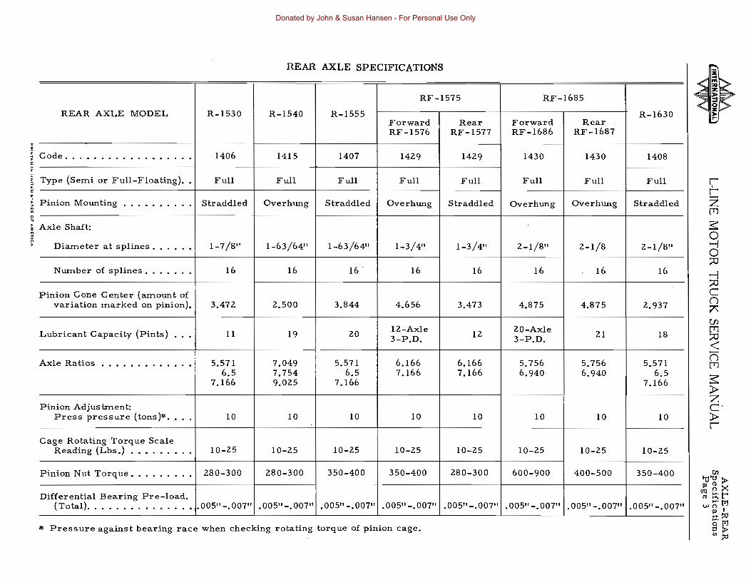

---
-----
-- ----
---
---
---
----
-----
---
-----
REAR AXLE SPECIFICATIONS
REAR AXLE MODEL R-2475 R-2580 R-2585 R-2590 R-2600 R-2740 R-2741 R-2800
Code 1426 1413 1412 1427 1414 1422 1423
Type (Semi or Full-Floating)bull Full Full Full Full Full Full Full Full
Pinion Mounting bullbullbull Overhung Overhung Overhung Overhung Overhung Overhung Overhung Overhung ~ C zAxle Shaft I [l1
Diameter at splines bullbull 1-3411 1-636411 1-7811 1-7811 2-1811 2-3811 2-3811 2-3811 3 o --l
Number of splines bullbullbullbullbull 16 16 16 16 16 16 16 16 o ----- 0
Pinion Cone Centers (amount of --l 0variation marked on pinion) 5281 4B12 5281 C ()
Lubricant Capacity (Pints) bullbullbull 22 20 22 37 37 37 ~
---- fJ) [l1
Axle Ratios bullbullbullbullbullbullbull 613-BI0 5571-7594 5571-7749 595-730 5571-7594 493-591 493-5lt1 493-591 0 670-886 65-BB66 6166-8577 613-B15 6500-8866 642-838 642-838 642-838 lt65-9041 666-885 699-838 699-838 699-838 n
[l1
Pinion Adjus trnen t 3Press pressure (tons) bull 10 10 10 25 25 25 raquo z
cCage Rotating Torque Scale raquoReading (Lbs) bullbullbullbull 10-25 10-25 10-25 4-5 amp 4-5 amp 4-5 amp r ~--
Pinion Nut Torque (Ft Lbs) bull 350-400 280-300 350-400 BOO-IIOO 800-1100 800-1100
Differential Bearing Pre-load (Total)bullbullbullbullbullbullbullbull 005 -007 005-007 005 -007 See Note See Note See Note ggtgtshy
t1I gtlt81 tM
U () I Pressure agains t bearing race when checking rotating torque of pinion cage Pl~~ OQ M
amp Tirnken Axle (I) g gtshyNOTE Tighten one notch each from 000 end play J1Ul~
Donated by John amp Susan Hansen - For Personal Use Only
AXLE-REAR Specifica tions Page 6
Socket
FT LBS WRENCH TORQUE A
1 foot200 2 feet
1-12 feet250 2 feet
1-IZ feet 300 Z feet
3 feet
2 feet 2-12 feet
350 3 feet 3-12 feet
2-12 feet 3 feet450 3-12 feet 4 feet
3 feet 3-12 feet500 4 feet 4-12 feet
3-12 feet 4 feet550 4-12 feet 5 fee t
4 feet 4-12 feet600 5 feet
15-12 feet I
Wrench Torque Chart
L-LlNE MOTOR TRUCK SERVICE MANUAL
B
Handle A-22879
EFFORT ON WRENCH (APPROX)
B
200 Ibs 1001bs
170 Ibs 125 Ibs
200 Ibs 150 1bs 100 1bs
175 1bs 140 Ibs 118 1bs 100 1bs
180 Ibs 150 1bs 129 1bs 113 1bs
167 Ibs 1441bs 1Z5 lbs 112 1bs
158 1bs 1371bs 123 1bs 110 Ibs
1501bs 1341bs 1Z0 Ibs 110 1bs
The above chart illustrates the length of the wrench handle (A) and the effort that must be applied at (B) when tightening to secure the indicated torque
Donated by John amp Susan Hansen - For Personal Use Only
AXLE-REAR Section AL-L1NE MOTOR TRUCK SERVICE MANUAL
Page I
AXLES-REAR
GENERAL INSTRUCTIONS FOR ALL HYPOID AXLES
HYPOID REAR AXLES (ALL MODELS)
All rear axles have a hypoid ring gear and pinion whether single reduction double-Teducshytion double-reduction (single and two-speed final drive) and two-speed differential Hypoid gears have a greater inherent torque capacity due largely to the fact that the hypoid pinion is much larger in diameter and the pinion teeth are correspondingly larger than those found in a spiral bevel pinion for the same number of teeth and the same diameter ring gear
The hypoid pinion has a longer face because of its offset location It also has larger tooth surface areas and usually has more teeth in ins tant contact with the gear It is thes e design characteristics which contribute to greater strength and quieter final drive operation Beshycause of this greater tooth contact it is more difficult to secure correct pinion setting at time of overhaul or when replacing differential bearings and every effort must be made to be sure the final setting results in best possible tooth contact
Note that the pmlOn center line (E F) is offset from the ring gear center line (C D)
~~-----------D
F
pinion
A-2282B
Fig I - Illustration shows location of pinion in relation to center 1 ine of ring gear Center line of pinion is below center line of ring gear
NOTE When adding to or replacing lushybricant in a rear axle having hypoid gears use only hypoid lubricants (See under Lubricashytion on page 9)
REAR AXLE HYPOID GEAR REPLACEMENT AND ADJUSTMENT
Hypoid Gear Tooth Contact (All Models)
The proper adjustment of hypoid gears in assembly is a vital factor in obtaining quiet and durable gears and the same methods of adjustshyment applies to both straight spiral bevel and to hypoid type gears
There are two distinct considerations in obtaining the proper tooth contact cone center and backlash
Hypoid as well as bevel and spur gears are cut with a predetermined amount of backlash The backlash usually varies from 004 to 005 on small gears and increases on large gears Generally the gears are machined to run flush with each other at the outer end (heel or large end) of the tooth and gears should be set according to their theoretical cone center (Figs 2 3 and 4)
Cone Center Specifications
Matched and mated hypoid ring gears and hypoid pinion gears are furnished both for service and for production
Mated gears are marked with figures showing the amount of variation from their theoretical cone center
Tbeoretical cone center of _ bevel drive gear and pinion
~~~Ii--Ilt-~ ~ ~
I i
Fig 2
Fig 2 illustrates a hypoid ring gear and pinion adjusted to theoretical cone center wherein the cone centers of both gears coincide The specifications in this case would be the distance from the line (A B) (Fig 1) drawn through the center of the hypoid ring gear to the ground face of the hypoid pinion on center line (E F) On some axles the pinion is loshycated above the center line (C D) (Fig 1) In these cases the term hypoid still applies
PRINTED IN UNITED STATES OF EAtCA
A-22797
Donated by John amp Susan Hansen - For Personal Use Only
AXLE-REAR Section A L-UNE MOTOR TRUCK SERVICE MANUAL Page 2
center of pinion Bracket screw
Fig 3
Fig 3 illustrates a setting wherein the mating of the gears has necessitated the pinion cone center being farther than the ring gear center The pinion marking in this case will be minus (-) because the distance from the ring gear center is less
~M eo~_bd driv gw01 ~~- -
- i a A-22BOI
Fig ~
Fig 4 illustrates a condition where the mating of the gears required the pinion cone center to be farther OUT The pinion marking will be plus (+) because the distance is greater
SE-1065 Pinion Setting Gauge
The SE-I065 pinion setting gauge is a preshycision gauge designed for use in adjusting differentials to the proper cone setting of the ring gear and pinion It is used only in adjustshyment of matched sets of gears A step plate and bracket have been added to the set so that the gauge may be used on all hypoid differenshytials with satisfactory results NOTE Be sure to allow for thickness of the step plate 400 when making calculations (Fig 5)
The use of SE-I065 gauge makes possible the exact duplication of the setting etched on the pinion This results in the best possible setting with a minimum loss of time It is adshyvisable to check all pinion settings with a paint impression before considering the work comshyplete By so doing visible proof of the pinion gauge setting accuracy is obtained also long and quiet gear performance is assured
Adjustment of differentials is a simple matter with the SE-I065 gauge Briefly it is only necessary to
1 Install pinion and bearing assembly in differential carrier
A-22494
Fj g 5
Fig 5 shows SE-I065 tool equipment in position on hypoid differential case Make certain that the bearing bores are clean and free of nicks or burns The step plate must be placed on the pinion end so that the lugs in the step plate straddlt the bearing staking inshydentations on the smaller axles
2 Install step plate and bracket as shown in Fig 5 CAUTION Be sure lugs on step plate straddle the bearing staking indentashytions
3 Mount assembled SE-I065 gauge in bearing bores of carrier
4 Take micrometer reading to check point of pinion Add 40011 (thickness of step plate) to reading Write down reading
5 Locate specified cone center specification for particular model on chart Write down specified figures
6 Locate on pinion the etched marking which indicates variation from zero cone center If a minus figure subtract from specified cone center and if a plus figure add to specified cone center Results of calculashytion give corrected cone center
7 Comparison of corrected cone center (6) with actual measurement (4) indicates amount of change necessary for pinion position
8 Install ring gear and carrier in position
9 Adjust backlash according to marking on ring gear
(See following page)
Donated by John amp Susan Hansen - For Personal Use Only
AXLE-REAR Section AL-UNE MOTOR TRUCK SERVICE MANUAL
Page 3
Example of Mathematics involved
Truck model to be L-llO
(a) Micrometer reading (add 400 for step plate) bull 34400
(b) Specified cone center on chart bull 340011
(c) Pinion marked (-5) 005
(d) Subtraction (b-c) gives corrected cone center 3395
(e) Subtract corrected cone center (d) from actual measurement (a) bull 045
(f) It is necessary to move pinion INbull
(g) Remember -- It is essential to arrive at a measurement as nearly equal the corrected cone center as possible
(h) DO NOT FAIL TO VERIFY ACCURAshyCY OF THE ADJUSTMENT SECURED WITH THE SE-l065 gauge by checking the gear tooth contact using the paint impression method as set forth under General Rear Axle Hypoid Pinion and Ring Gear Adjustment which follows
GENERAL REAR AXLE HYPOID PINION AND RING GEAR ADJUSTMENTS
(PAINT IMPRESSION METHOD)
The following general instructions and suggestions are for the benefit of those service stations not equipped with an SE-l065 pinion setting gauge Bear in mind that the accuracy of the adjustment obtained with the following procedure is dependent upon the skill of the operator
Hypoid gears when mounted should show a bearing toward the toe or small end of the tooth never atthe heel or large end the reason being that it is practically impossible to make gears and gear mounting rigid enough so that there will not be some slight deflection when fullloadis applied This always has a tendency to caus e the bearing to come on the heel of the tooth and when gears are adjusted so that the bearing is toward the heel of the tooth it reshys ults in a concentration of load on the top corshyner of the heel and breakage will follow
Checking tooth contact is accomplished by means of oiled red lead applied lightly to the bevel gear teeth (Fig 6) When the pinion is rotated the red lead is squeezed away by the contact of the teeth leaving bare areas the exact size shape and location of the contacts
Fig 6
Fig 7
Sharper impressions may be obtained by applying a small amount of resistance to the gear with a flat steel bar and using a wrench to rotate the pinion When making adjustments check the drive side of the bevel gear teeth Coast side contact should be automatically corrected when drive side contact is correct As a rule coating about twelve teeth is suffi shycient for checking purposes
With adjustments properly made the correct tooth contact shown in Fig 7 will be secured The area of contact starts near the toe of the gear and extends about 80 permiddot cent of the tooth length This adjustment results in a quiet running gear and pinion set which because the load is distributed over the te eth within the proper area will deliver all the long service built into it
Figs 8 to 11 illustrate method of adjustshyment in securing the proper gear tooth contact
PRINTED IN UNITED STATES OF AMERICA
Donated by John amp Susan Hansen - For Personal Use Only
AXLE-REAR Section A L-UNE MOTOR TRUCK SERVICE MANUAL Page 4
A HIGH NARROW CONTACT IS NOT DESIRABLE If gears are allowed to operate with an adjustment of this kind noise galling and rolling over of the top edges of the teeth will result To obtain correct contact move pinion toward bevel gear to lower contact area to proper location This adjustment will decrease backlash between pinion and bevel gear teeth which may be corrected by moving bevel gear away from pinion Backlash of
006 to 012 is correct
Fig 8
A LOW NARROW CONTACT IS NOT
DESIRABLE If gears are allowed to opershy
ate with an adiustment of this kind galling
noise a nd grooving of teeth will result To
obtain correct contact move pinion away
from bevel gear to raise contact area to
proper location Correct backlash of 006
to 0l2f may be obtained by moving
bevel gear toward pinion
Fig 9
A-15848
A Conlac1 adjustmeuront
B Sack lash correction
Amiddot15847
A CONTACT
AOJUSTMfNT
B BACK LASH
CORRECTION
A SHORT TOE CONTACT IS NOT DEshy
SIRABLE If gears are allowed to operate
with an adiustment of this kind chipping
at tooth edges and excessive wear due to
small contact area will result To obtain
correct contact move bevel gear away
from pinion This will increase the lengthshy
wise contad and move contact toward heel
of tooth Correct backlash of 006 to 012
can be obtained by moving pinion toward
bevel gear
Fig 10
A SHORT HEEL CONTACT IS NOT DEshySIRABLE If gears are allowed to operate with an adiustment of this kind chipping excessive wear and noise will result bull To obtain correct contact move bevel gear toward pinion to increase the lengthwjse contact and move contact toward toe Corshyrect backlash of 006 to 012 can be obshytained by moving pinion away from bevel gear Several adiustments of both pinion and gear may be necessary before correct confact and backlash are secured
Fig I I
A CONTACT
4OJUSTMENT
B BACK lASH
CORRECTION
A CONTACT
ADJUSTMENT
B BACK LASH
CORRECTION
AmiddotJSBSO
A-15849
Donated by John amp Susan Hansen - For Personal Use Only
AXLE-REAR Section AL-L1NE MOTOR TRUCK SERVICE MANUAL
Page 5
Gear Adjustment for Lash
Generally if original gears are being reinshystalled red leading of teeth will not indicate the same contact as new gears and can be misshyleading Gears that have been in service for long periods form running contacts due to wear of teeth therefore the original shim pack should be maintained to check gear lash Gear lash when using original gears can be reduced only to a point of smooth rotation of gears
If the gear lash is in excess of maximum tolerance as stated under Gear Adjustment the lash may be reduced only in the amount that will avoid overlap of the worn tooth section (Fig 12) Rotate the gears and check for smooth or rough operation If a slight overlap as illustrated (Fig 12)takes place at the worn tooth section rotation will be rough
Worm section Pinion too deep in of ring gear ring gear
Ring gear Overlap
Correct Incorrect
A-19693
Fig 12
Fig 12 illustrates worn condition of gear teeth and overlapping condition
When installing new gears check gear lash with dial indicator (Fig 13) and adjust to obtain amount of backlash marked on ring gear as follows
1 Set pinion according to procedure outlined under SE-I065 Pinion Setting Gauge
2 To move ring gear tighten or loosen differential bearing adjusting nuts as reshyquired
3 After correct gear lash is secured check and adjus t as neces s ary to obtain the correct tooth contact (See Gear Adjustshyment for correct tooth contact)
PRINTED IN UNITED STATEs OF AMERICA
Fig 13 - Checking gear lash
Adjust Differential Bearing Pre-Load
Using dial indicators at side of each bearshying cap (Fig 14) adjust to obtain bearing preshyload as follows
1 Loosen adjusting nuts only enough to notice end play on indicators
2 Tighten adjusting nuts only enough to obtain 000 end play reading on indicators
Note While gear is held in 000 end play and before loading bearings check gear for runout If runout exceeds 008 reshymove differential and check for cause
Dial indicators
Fig I~ - Adjusting differential bearing preshyload
Donated by John amp Susan Hansen - For Personal Use Only
AXLE-REAR Section A L-UNE MOTOR TRUCK SERVICE MANUALPage 6
3 Tighten BOTH adjusting nuts from 000 end play to pre-load differential bearings Adjust pre-load to secure equal pre-load reading at indicators (See specifications for pre-load data on the various axles)
4 Tighten bearing cap stud nuts to specified torque
5 Install adjusting nut locks
Pinion Bearing Adjustment for Correct Pre-Load (Torque Method)
After the pInIon the pInIOn bearings and spacers have been assembled in the pinion bearing cage place the assembly in a press being sure to use a sleeve adapter as shown in Fig 15 Press the bearing down firmly and rotate the pinion cage to align the bearings and assure normal bearing contact Set press at correct pressure and attach a spring scale to pinion cage as indicated in Fig 15 Read scale only while pinion cage is turning If preload reading is incorrect thE7 bearing load may be increased by installing a thinner spacer ot decreased by using a thicker spacer
The correct press ram pressure and scale reading for the various axles may be found in the Rear Axle Specifications
Fig 15
Fig 15 shows method of checking pinion bearing preload using scales to measure torque
Pinion Bearing Adjustment for Pre-Load Using Dial Indicator (This method should only be used on the smaller axles)
An outside or bench assembly should be made of bevel pinion bearings and cage With cups assembled in cage assemble the pinion and inner bearing cone and roller assembly in place using the proper spacer to space the pinion bearings Next assemble the outer pinshyion bearing cone and rollers spacer companshyion flange washer and nut
Fig 16
Fig 16 shows method of attaching dial indicator when adjusting bearing pre-load This method can be used when press equipment is not available
NOTE Do not install pinion bearing oil seal until all adjustments have been completed Then check bearing fit to see that bearings have no end movement with flange nut drawn up tight To secure this fit proper spacer must be found by trial as follows
(I) Place assembly in vise in position shown (2) Mount indicator on propeller shaft flange
with indicator finger resting on upper face of cage (See A Fig 16)
(3) With the tips of the fingers grasp the bearshying retainer and work bearings up against the back face of pinion (See B Fig l6)
(4) With the bearings held firmly against the pinion move the cage up and down obshyserving the indicator reading It is imshypossible to accurately determine the end play unless the bearing is worked loose and up against the pmIon Assemblies having as much as 005 end play cannot be moved enough to show on the indicator until the bearing has been worked up and away from the cup
CAUTION
Bearings must be absolutely clean
Donated by John amp Susan Hansen - For Personal Use Only
AXLE-REAR Section AL-UNE MOTOR TRUCK SERVICE MANUAL
Page 7
Preload the pinon bearings by replacing the spacer between the pinon bearings with one smaller to the extent of the amount of the end play plus 002t for the loading For example should there be 005 end playas indicated in the sketch in the assembly replace the spacer with one 001 smaller Do not depend upon the spacers to be right according to number but check each and everyone with an accurate micrometer Before reassembling the bearshyings to the pinion shaft they should be dipped in rear axle lubricant Propeller shaft flange nut must be pulled down securely to assure tight bearings A wrench with 30 11 of leverage should be used
In order to determine if insufficient or excessive preload has been applied make the following te st
(1) Place assembly in vise with jaws clampshying together on the flange of the pinion bearing cage and with assembly in a hori shyzontal position
(2) Grasp the propeller shaft flange with one hand and attempt to turn
(3) If the pinion turns freely assembly is too loose If pinion cannot be turned assemshybly is too tight
(4) The ideal condition is to secure a firm drag when turning the pinion cage by hand
After proper bearing fit has been obtained place pinion bearing cage shims approximately 020 in thickness over end of cage and place cage and pinion assembly in carrier it being necessary to match flange holes in cage since one hole is out of equal spacing to assure propshyer position of cage Next assemble two cage bolts only until gear setting is completed Assemble differential and bevel gear assemshybly and place bearing cap and adjuster in posishytion Tighten bearing cap bolts and back off slightly to provide sufficient Iposeness to allow turning the adjuster for a temporary backlash adjustment of approximately 01 Ot After this adjustment has been made tighten each bearing adjuster snug then give them a final tightening operation drawing them up to secure the 005 to 007 total bearingpre-load This is imshyportant in order to make certain that the bearshyings are seating properly
IMPORTANT Hypoid drive pmlon oil seals must be soft and pliable before being inshystalled if the seals have become dried out and hard while in stock use kerosene and work it in thoroughly When seal has become soft and pliable dip it in hot oil and work this oil in thoroughly
PRNTED IN UNITED STATES or A ME JltIICA
Fig 17 - Using the pinion staking tool
Pinion Bearing (Straddle bearing)
The straddle pinion bearing is held in place on the pinion by a staking operation
The staking operation is accomplished through the use of a hydraulic or screw press applying 18 to 20 tons pressure on the special staking tool as illustrated in Fig 17 The reshysult will be uniformly spaced ball indentations that securely lock the pinion bearing to the shaft
Differential Ring Gear Rivet Removal
If necessary to remove hypoid ring gear or herringbone gear rivets drill the rivet heads from the gear side using a drill slightly larger than the rivet itself Use a punch for the reshymoval of the remaining portion of the rivet (See Fig 18)
Knocking off or busting rivets is a danshygerous practice both from the standpoint of personal safety and because such practice may cause distortion to the gear carriers or gears and will elongate the rivet holes
Rivet Pressures
Proper installation of differential ring gear rivets demands that sufficient pressure be applied to the rivets to expand them and cause them to completely fill the holes in which they are installed Riveting should be done with COLD rivets Hot rivets will shrink when cool leaving s space and inviting shearing upon the application of torque
A-22727
Donated by John amp Susan Hansen - For Personal Use Only
AXLE-REAR Section A L-UNE MOTOR TRUCK SERVICE MANUALPage 8
Difierential case
A-22831
Fig 18 - Drill rivet head and punch-out rivet as shown
Riveting Jig SE-1575 is available and is designed for use with hydraulic or ITlechanical press equipITlent
The following pressures are recoITlITlended for differential ring gear rivet installation
PRESSURE RIVET SIZE PER RIVET
(INCH) (TONS)
516 12 to 15 38 17 to 20 716 30 to 35 12 45 to 50 916 60 to 70 58 60 to 70
Axle Shaft Removal (Timken Axles)
Axle shafts are attached to the wheel hubs by studs and nuts at the flanged ene Stud holes in each axle shaft flange are taper-reaITled to receive split tapered dowels
When disasseITlbling the axle SOITle of the bearing cage studs or axle shaft studs ITlay turn loose froITl the housing rather than at the nuts When the axle is reasseITlbled the nuts should be reITloved froITl the studs and the studs reshyplaced in their tapped holes before installing the cage or carrier
When reITloving the axle shafts froITl the Tirnken axle reITlove the stud nuts and lockshywashers and proceed as indicated in Figs 19 20 21
Aloon
Fig 19 - Using a heavy hammer strike sharply on the center of the flange of the axle shaft This wi II unseat and loosen the tapered dowels in each stud hole
Fig 20 - Remove the tapered dowels Note When reassembling there must be a sl ight clearance between the lockwasher and axle shaft driving flange Excessive wear onstuds dowels or holes in the flange wi 11 indicate a lack of clearance at this point
Donated by John amp Susan Hansen - For Personal Use Only
9
AXLE-REAR Section AL-UNE MOTOR TRUCK SERVICE MANUAL
Cap Spring
Valve body
Rear axle breather valve
Location of breather valve on heavy duty axles
Fig 21 - Push the axle shaft flange back into position against the wheel hub and again strike a sharp blow in the center of the axle shaft flange This will cause thi axle shaft to spring away from the wheel hub and allow reshymoval of the axle shaft without resorting to the use of a pry bar or screwdriver Do not pry between the axle shaft flange and wheel hub To do so is apt to damage the seal asshysembly or machined surfaces of the wheel hub or axle shaft flange
When reinstalling the axle shafts the re must be a slight clearance between the lockwashers and driving see Fig 20 Excessive wear on studs dowels or hole s in the axle flange will take place when no clearance exists
Axle Housing Breather Valve
When the rear axle becomes warm after a short period of operation a pressure is built inside the axle housing To prevent this presshysure from forcing lubricant past the rear wheel oil seals and damaging the brake linings a breather valve has been provided The valve is so constructed that warm air may pass out of the axle to relieve built up pressure yet dirt and moisture are prevented from entering The location of the breather valve is shown in Fig 18 inset shows detail of valve
The breather valve should be kept open and clean When the vehicle is operated or unshyimproved highways or in ice and snow it is possible that dirt will be forced under the valve cap thus rendering the valve ineffective Reshymove valve occasionally and clean thoroughly in a cleaning solution
NOTE Where power divider is mounted on rear axle the breather is mounted on upper side of the power divider
PRINTEO IN UNITEO STATES OF AMERICA
Fig 22 - Keep breather valves clean and free of obstruction Breathers are usually located in housing as illustrated
IMPORTANT
Lubrication Of Hypoid Axles
The lubricant used in hypoid axles is an important factor in obtaining long gear life and satisfactory drive unit service Past experishyence proves that a large portion of service problems can be traced to using incorrect or lubricant of poor quality
In the selection of Hypoid Lubricants it is advisable to consider using products of unquesshytionable quality
Because of the higher unit pressures and sliding tooth characteristics of hypoid gearing the lubricant must have properties which enshyable it to withstand these actions
It is important that the axle hypoid gearing receive initial lubrication after overhaul or when a vehicle has been standing in storage and BEFORE THE AXLE IS SUBJECTED TO HEAVY LOADS Good practice is to check the lubricant level in the axle housing then JACK UP BOTH rear wheels and operate the vehicle in high transmission gear at approximately 25 miles per hour for five minutes This will assure thorough lubrication of the gearing beshyfore the unit is placed into service (Do not allow one wheel to race faster than the opposite wheel)
Where the axle pinion cage is provided with a plug at the pinion cage insert one pint of lubricant to provide initial lubrication for the pinion bearing
Donated by John amp Susan Hansen - For Personal Use Only
AXLE-REAR Section A L-UNE MOTOR TRUCK SERVICE MANUAL Page 10
Specified Lubricant For Hypoid Axles
For hypoid axles (not Eaton) use SeL EP gear oil or a multi-purpose gear lubricant suit shyable for hypoid axles and supplied by a reputashyblerefinery SAE-90for cold climate and SAEshy140 for warm climate For Eaton hypoid axle use a hypoid gear lubricant available as Elco Gear Safety 1281 or its equivalent A number of hypoid lubricantes are prepared by reputable companies which contain Elco additive concenshytrates (See Lubricationlf
section A)
NOTE When reassembling the differential gears thrust washers cross shaft spur gears and bearings lubricate the wearing surfaces with a light coat of the specified axle lubricant
Differential Assembly -- L-110 and L-120
The L-110 and L-120 Series Trucks use differential assemblies that are identical in construction except that a spacer or thrust block is used when the unit is installed in a L-110 axle
Since the L-110 axle is of semi-floating construction a means of taking up the end thrust of the axles and wheels must be proshyvided The block serves this purpose The wheel bearings pick up the end play or thrust on the L-120 (full-floating) axles and no thrust block is needed Also the axle shafts in the full-floating design are slightly longer than those used in the semi-floating design and for this reason the thrust block must be removed when the differential unit is used in the L-120 series vehicle
Removal of the thrust block is as follows
1 Drive cross pin retainer pin from differshyential case so as to clear the cross pin (Fig 23)
2 Using punch drive the cross pin out of differential case far enough to remove the thrust blocks (Fig 24)
Retainer
Fig 2
3 Push cross pin back into position in the differential case Drive retainer pin into position and stake case to secure retainer pins (Fig 25)
Stake the case to secure
retainer pin
Fig 25
Amiddot2J436
Fig 23 - Driving retainer pin from differenshytial case using a hammer and punch
Donated by John amp Susan Hansen - For Personal Use Only
AXLE-REAR Section ALmiddotLJNE MOTOR TRUCK SERVICE MANUAL
Page 11
SINGLE-REDUCTION HYPOID AXLE (UNIT SHOWN IS MODEL R-1060 OR R-1070)
1 2 3 4 5 6 7 8 9
10 11 12 13 14
Fig 26 - Sectional Companion flange Propeller shaft mounting nut Propeller shaft mounting nut washer Pinion shaft bearing oil seal Pinion bearing cage to carrier capscrew Pinion bearing cage Pinion bearing outer Pinion bearing Pinion bearing Hypoid pinion gear (straddle mounting) Pinion bearing Difpounde rential side gear Axle housing Differential bearing adjuster lock
Amiddot22643
View of Hypoid Rear Axle IS Differential cross pin 16 Hypoid ring gear 17 Hypoid ring gear rivet 18 Diffe rential pinion 19 Axle shaft 20 Differential bearing adjuster 21 Differential carrier to housing gasket 22 Differential carrier to housing capscrew 23~ Differential roller bearing 24 Differential center block 25 Differential cross pin retaining pin 26 Differential case 27 Differential carrier housing 28 Pinion bearing cage shim
NOTE Rear Axle R-l070 is identical with above description except differential center block (24) is not used
PRINTEO IN UNITEO STATES 0 6MERICA
Donated by John amp Susan Hansen - For Personal Use Only
AXLE-REAR Section A L-UNE MOTOR TRUCK SERVICE MANUAL
12
SINGLE-REDUCTION HYPOID AXLE (MODELS R-1165 R-1170 R-1440 R-1470 R-1530 R-1555 R-1630)
30 29 28 27 26 25 24 23 22 21---l
------6 7 8 9
Fig 27 - Sectional
1 Axle housing 2 Hypoid ring gear 3 Differential bearing cap 4 Differential bearing cap mounting stud 5 Differential bearing 6 Differential bearing adjuster 7 Oil pascage to pinion bearings 8 Pinion bearing cage shims 9 Pinion bearing cage
10 Pinion oil seal retainer 11 Pinion oil seal 12 Slinger 13 Companion flange 14 Thrust washer 15 Propeller shaft companion flange nut 16 Pinion cage mounting capscrew 17 Differential carrier mounting capscrew 18 Pinion bearing cage cork seal 19 Thrust washers
View of Hypoid Rear Axle
20 Pinion bearing outer 21 Pinion bearing spacer 22 Pinion bearing inner 23 Hypoid pinion (straddle mounting) 24 Pinion bearing 25 Differential case bolt lockwire 26 Differential case bolt 27 Differential carrier 28 Differential carrier mounting gasket 29 Axle shaft 30 Diffe rential bearing adjuste r lock 31 Differential side gear thrust washe r 32 Differential case plain half 33 Differential side gear 34 Differential spider pinion 35 Differential spider pinion thrust washer 36 Differential spider 37 Differential case flanged half
Donated by John amp Susan Hansen - For Personal Use Only
AXLE-REAR Section BL-UNE MOTOR TRUCK SERVICE MANUAL
Page 1
TWO-SPEED AXLES SEE SECTION Hit FOR ELECTRIC SHIFT
A2UI4
Fi g I - Two-Speed Axle (Eaton)
1 Hypoid ring gear 17 Bearing inner 33 Axle shaft 2 Oil collector drum 18 Hypoid pinion 34 Bearing adjuster lock 3 Ring gear case 19 Bearing spacer 35 Bearing adjuster 4 Thrust washer 20 Bearing outer 36 Bearing cap 5 Bearing cap stud 21 Companion flange 37 Thrust washer 6 Bearing cap 22 Washer 38 Side gear thrust 7 Carrier bearing 23 Nut washer 8 Clutch plate 24 Cage capscrew 39 Side gear 9 Sliding clutch 25 Slinger 40 Differential pinion
lO Shift fork 26 Seal 41 Pinion thrust washer 11 Shift fork shaft 27 Washer 42 Differential case 12 Clutch plate 28 Pinion cage 43 Pinion gear spider 13 Sliding clutch 29 Shims 44 Ring gear case 14 Diaphragm seal 30 Carrier 45 Idler pinion pin 15 Gear case bolt 31 Carrier capscrew 46 Idler pinion gear 16 Shifter motor stud 32 Gasket 47 Axle housing
PRINTED IN UNITED STATES OF AMERICA
Donated by John amp Susan Hansen - For Personal Use Only
AXLE-REAR Section B L-LlNE MOTOR TRUCK SERVICE MANUAL Page 2
EATON TWO-SPEED REAR AXLE
The two-speed rear axles are full-floating hypoid drive type having four planetary gears which mesh with an internal gear on the hypoid ring gear
The primary reduction is accomplished through the hypoid ring gear and a straddleshymounted hypoid pinion The secondary reducshytion is accomplished with a sliding clutch serving to lock or unlock the planetary gears
Serving
The correct servlcmg of this unit as is true with any mechanical equipment is imporshytant to satisfactory operation and life Servicshying the two-speed unit does not require special tools The ordinary equipment found in most shops is sufficient for this work Use the folshylowing step-by-step procedure for disassemshybling Direct reversal of the action will be the proper reassembly procedure (See Shop Talk No 1 for step-by-step illustrations on disasshysembly)
Disassembly
Remove differential carrier assembly complete from the truck following the same procedure as you would to take out a single or double reduction unit except in this case the two wires on the shift unit must be disconshynected For convenience in handling the head maybe placed in the end of a clean small drum The opening should be large enough to accept the bevel drive gear and bearing caps Then proceed as follows
1 Remove the two shift housing to carrier stud nuts and lockwashers and pull off shift unit assembly (See section IIH for electric shift instructions)
2 Remove plug washer spring capscrew lockwasher and oil distributor
3 Pull out shift fo rk shaft aite r removing shift fork shaft retainer (Fig 2) The shift fork may then be slipped from the sliding clutch gear and removed through the back of the differential carrier
4 Slip out sliding ~lutch gear
5 Mark right hand differential bearing adshyjuster with punch (This is for relocating when reassembling)
6 Remove bearing cap bolt lockwires on both right and left hand sides Loosen cap bolts only Take off right hand bearing adjuster lock and cotter pin
7 Remove left hand differential bearing cap adjuster and lock as an assembly to assure
correct positioning of gear on reassembly (When reassembling hold adjuster and bearing cap up away from threads in bore of carrier unit cap bolts are started Drop cap the threads of the adjuster and those in carrier will mesh freely)
8 After removing bearing caps tip up left hand end of planetary unit and lift out
9 Remove pinion bearing cage capscrews
10 Using a suitable puller remove pinion assembly from carrier May also be reshymoved by using a brass drift and tapping lightly from the inside (Note shims under pinion bearing cage)
I L Remove pinion shaft nut and slide off comshypanion flange
12 Lift off pinion bearing cage bearing washer and spacer
13 Drive off pinion bearing cage by tapping lightly between teeth of pinion alternately on opposite sides of inner race CA UTION Exercise care so as not to damage bearing during this operation
12 Remove pinion bearing cone and washer cage assembly Take out pinion bearing cage cork (Replace this cork with every repair)
15 Remove lockwires nuts and bolts from planetary unit (support case)
16 Tap alternately on opposite sides of ring gear with head of rawhide hammer until gear is free of Hange on support cas e (When reassembling use two bolts to asshysure proper alignment of bolt holes)
17 Lift off left hand support case and bevel drive gear
lH Pry off high speed clutch plate and take out idler pinions and pins
19 Lift out entire differential asseITlbly and remove support case thrust washer
20 Take out differential case bolt lockwire and remove bolts (Note short bolts beshytween spider arms)
21 Lift off right hand differential case Pick up long hub side gear right hand and slip off thrust washer (Note-chamfered side of washer agains t back face of gear)
22 Pull out spider and di[feren tial s ide pinshyions noting thrus t washers behind pinions Slip washers and pinions off spider arms Take out short hub side gear left hand
Donated by John amp Susan Hansen - For Personal Use Only
AXLE-REAR Section BL-UNE MOTOR TRUCK SERVICE MANUAL
Page 3
and remove thrust washer (Note chamshy Gear Tooth Contact fered side of washer against back face of gear )
23 Remove differential bearing cones by striking inner race on alternate sides through holes provided in the support case
24 In reassembling the pinion use SE-I065 pinion setting gauge in adjusting matched sets of pinions and ring gears to proper cone settings (Theoretical cone centers for various axles are found under Specifi shycations Rear Axle Section)
REASSEMBLY -- IMPORTANT
Assembling Differential Unit Lubricate both sides of all thrust washers
well Chamfered sides of washers must be against back face of side gears Lubricate spider arms side-pinion bores and side-gear hubs Draw bolts tight with long-handled wrench and securely fasten with lockwire
Assembling Planetary Unit Before placing thrust washer lubricate
both sides well Cover idler-pinion pins with lubricant Chamfered teeth on high-speed clutch plate must face pinions Place notches in oil-collector drum between bolt holes in bevel gear Draw bolts tight with long-handled wrench and secure wire
Pinion Shaft Bearing Adjustment Desired bearing tension is obtained by usshy
ing a spacer of the correct thickness between the bearing inner races There are 12 spacers each of different thickness available for this purpose To make the assembly proceed as follows 1 Place the pinion and bearings in position
in the cage using original spacer providshying the pinion did not have any perceptible end movement before disassembly
2 Then assemble flange washer and flange Tighten retaining nut securely There should be no perceptible end play and bearshying should roll freely If correction is to be made select proper size spacer to obshytain desired fit
Assembling Differential Carrier Unit Lubricate all bearings as they are assemshy
bled in carrier After adjusting gear be sure cap bolts are tight Wire bolts securely inshycluding capscrews in adjuster lock
Pinion Bearing Pre-Load Follow instructions given in Hypoid Rear
Axle Section HAll page 6
Differential Carrier Bearing Pre-Load
The correct procedure for securing the specified carrier bearing pre-load as listed in the Rear Axle Specification for these axles will be found in Section All Hypoid Rear Axles
PRINTED IN UNITED STATES or AMERIG
To secure best possible tooth contact use SE-I065 pinion setting gauge and follow inshystructions under this heading Section A page 2 Check results obtained by making a paint impression test of tooth contact See Gear Adjustment for correct tooth contact - Paint Impression Method Section A page 3
Lubrication
An oiling system is provided to supply lushybricant within a half a turn of the truck wheels to the essential places during conditions when splash and dip alone would be insufficient A heavy coating of oil is picked up by the oil collector drum and transmitted to the oil scoop The oil scoop scrapes the oil from the drum and splits it into two courses One half of this lubricant goes to the pinion bearings the other half to the right hand differential and planetary unit to the left differential bearing and then returning to the reservoir
Whenever a two-speed differential (new or rebuilt) has been installed in the axle housing fill the oil reservoir to bottom of filler plug opening and replace plug Then add one addishytional pint of lubricant using filler hole provided at top of carrier housing just above pinion cage
Use a hypoid gear lubricant available as ElcoGear Safety 1t28lt or its equivalent Anumshyber of hypoid lubricants are prepared by repushytable companies which contain Elco additive concentrates Viscosity of the hypoidlubricant should be SAE-90 When high atmospheric temshyperatures (above 1000 F) prevail SAE-140 may be used See Lubrication section A
Fig 2
Donated by John amp Susan Hansen - For Personal Use Only
Donated by John amp Susan Hansen - For Personal Use Only
AXLE-REAR Section CL-UNE MOTOR TRUCK SERVICE MANUAL
Page 1
1 2 3 4 5 6 7 8 9
10 11 12 13 14 15 16
DOUBLE-REDUCTION AXLE (EATON)
~4i------
Carrier gasket Carrier Herringbone gear Gear rivet Oil distributor disc Case flanged half Case bolt and nut Thrust washe r Bearing cap Cap stud Lock ring Bearing Side gear Thrust washer Lock ring Oil scoop
PRINTED IN UNTEO STATES or- AMpoundRICA
Fig I shy
17 18 19 20 21 22 23 24 25 26 27 28 29 30 3l 32
Double-Reduction Axle (Eaton)
Spring and plug Axle shaft Counte r shaft bearing Pinion countersh3it Cage capscrew Bearing cage Carrier capscrew Cage shiITls Oil reservoir Hypoid pinion Bearing inner Bearing spacer Bearing outer Washer Slinger Companion flange
33 34 35 36 37 38 39 40 4l 42 43 44 45 46 47 48
13 14 15 16 17 18 19
20
A22813
Cotter pin Nut Washer Oil seal Bearing cage Cage shims Oil passage Hypoid ring gear Oil distributor disc Oil scoop Oil scoop capscrew Spider pinion Pinion thrust washer Case plain half Spider Axle housing
Donated by John amp Susan Hansen - For Personal Use Only
AXLE-REAR Section C L-UNE MOTOR TRUCK SERVICE MANUAL Page 2
EATON DOUBLE-REDUCTION REAR AXLE
The Eaton double-reduction rear axles shown in Fig 1 are heavy-duty double reducshytion type The primary reduction is through a hypoid ring and pinion gear while the secondary reduction is through a set of herringbone gears
Primary Reduction
The primary reduction gears are the hyshypoid type consisting of a hypoid pinion mounted on the forward end of the carrier housing and meshed with a hypoid ring gear which is riveted to an integral flange on the ring geariii shaft This shaft also carries as an integral part the herringbone drive pinion for the secondary reduction
Secondary Reduction
The secondary herringbone reduction gears consist of a drive pinion and a mating gear The teeth on the secondary reduction gears are right and left-hand spiral cut in line with each other forming a VI the apex of which is at the center of the gear face A center cut through the apex breaks the tooth line into two separate and opposed spiral gears each exert shying equal and opposed pressure thus balancing thE end thrust
Installing New Herringbone Drive Gear (Differential Case)
If new gears are being ins taIled the pilot diameter on differential case drive gear flange should be checked to see that it runs true If inspections indicate a run out of 004 a new differential case should be installed When assembling drive gear on face of flange make sure each rivet is tight The best results are obtained if a press is used to install rivets Follow the instructions outlined under Rivet Pressures on page 8 Section At
Hypoid Pinion Shaft and Adjustment
Adjustable hypoid pinion bearings are assembled to pInIOn shaft and retained by universal joint flange and nut on forward end of pinion shaft
A spacer (available in several thicknesses) is used to maintain correct distance between front and rear bearings and to secure the pinshyion bearings pre-load as indicated in Rear Axle Specifications The pinion cage is mounted in the conventional manner and the correct cone center adjustrnent is secured by means of a shim pack under pinion cage flange See SE-l065 Pinion Setting Gauge Section A page 2)
IMPORTANT Hypoid drive pinion oil seals must be soft and pliable before being inshystalled if the seLls have become dried out and hard while in stock use kerosene and work it in thoroughly When seal has become soft and pliable dip it in hot oil and work this oil in thoroughly
Pinion Bearing Lubrication
NOTE When reassembling differential to axle housing or new and dry differential is used from stock be sure to inject about one pint of differential lubricant into the pinion bearing housing through the filler plug opening at the side of the carrier This will provide immediate lubrication for the pinion bearings upon placing the unit in operation
Herringbone Gear Shaft (Cross Shaft)
The herringbone drive pinion gear shaft is mounted at right angles to the hypoid pinion shaft in the carrier housing This shaft is a one-piece steelpoundorging consisting of an integral herringbone gear in the center and an integral flange on one end to which is bolted a hypoid ring gear
To remove this shaft it is necessary to remove the differential and herringbone ring gear assembly Then withdraw the hypoid pinshyion and cage assembly far enough to clear the hypoid ring gear when being removed (Reshymoval of universal joint flange is unnecessary) Remove both bearing covers and using a soft hammer tap ring gear end of shaft until the bearing cup at opposite end of shaft is removed from carrier housing This will permit suffi shycient opening to partly pass shaft through until bearing is clear of carrier housing at ring gear end of shaft Tilt ring gear end of shaft to rear and withdraw from carrier
The cros s shaft bearing covers control the hypoid pinion and ring gear backlash and tooth contact as well as the bearing pre-load This is accomplished by means of a shim pack under each bearing cover
Herringbone Gear Adjustment
Herringbone gears are not adjustable for backlash This clearance is taken into account in the construction and remains constant as long as the gears remain undamaged or the differshyential carrier bearings are not worn excessiveshyly
The self-aligning differential carrier bearshyings eliminate the need for adjustment to align the herringbone pinion and herringbone ring gear The heavy duty roller bearings permit
Donated by John amp Susan Hansen - For Personal Use Only
AXLE-REAR Section CL-LINE MOTOR TRUCK SERVICE MANUAL
Page 3
the differential carrier to move sidewise within the bearing race sufficiently to keep both gears in perfect alignment at all times
Differential
Differential is convential four-pinion type with thrust washers back of side gears and pinshyions Cases are supported on heavy duty roller bearings
Differential Lubricators
The double reduction axles have special provision incorporated to supply oil to the hershyringbone pinion shaft bearings as well as the hypoid pinion shaft bearings This is accomshyplished by scooping lubricant from oil collector discs mounted on the herringbone gear and the hypoid ring gear The lubricant is picked up from these discs by oil scoops and circulated through special passages to the differential carshyrier bearings and the herringbone pinion shaft bearings Fig 2 illustrate s the flow of oil and the principal of this means of bearing lubricashytion
5
Fig 2
Lubrication of Hypoid Axles
The lubricant used in hypoid axles is an important factor in obtaining long gear life and satisfactory drive unit service Past experishyence proves that a large portion of service problems can be traced to using incorrect or lubricant of poor quality
In the selection of Hypoid Lubricants it is advisable to consider using products of unquesshytionable quality
Because of the higher unit pressures and sliding tooth characteristics of hypoid gearing the lubricant must have properties which enshyable it to withstand these actions
It is important that the axle hypoid gearing receive initial lubrication after overhaul or when a vehicle has been standing in storage and BEFORE THE AXLE IS SUBJECTED TO HEAVY LOADS Good practice is to check the lubricant level in the axle housing then jack UP BOTH rear wheels and operate the vehicle in high transmission gear at approximately 25 miles per hour for five minutes This will asshysure thorough lubrication of the gearing before the unit is placed into service (Do not allow one wheel to race faster than the opposite wheel)
Where the axle plmon cage is provided with a plug at the pinion cage insert one pint of lubricant to provide initial lubrication for the pinion bearings
NOTE When reassembling the differential gears thrust washers cross shaft spur gears and bearings lubricate the wearing surfaces with a light coat of the specified axle lubricant This will help provide initial lubrication
Use a hypoid gear lubricant available as ElcoGear Safety filS or its equivalent A numshyber of hypoid lubricants are prepared by repushytable companies which contain Elco additive concentrates Viscosity of the hypoid lubricant should be SAE - 90 When high atmospheric temshyperatures above 100 F) prevail SAE-I40 may be used
PRINTO IN UNITpoundO STATpoundS 01 AMERICA
Donated by John amp Susan Hansen - For Personal Use Only
Donated by John amp Susan Hansen - For Personal Use Only
AXLE-REAR Section DL-UNE MOTOR TRUCK SERVICE MANUAL
Page 1
SINGLE-REDUCTION AXLE (TIMKEN 100 SERIES AXLES)
Fig I - Single-Reduction Timken 100 Series Axle
1 Pinion shaft nut 19 Adjusting nut lock 2 Pinion shaft nut washer 20 Differential bearing cap 3 Companion flange or yoke 21 Side gear thrust washer 4 Oil seal 22 Side gear 5 Thrust washer 23 Pinion thrust washer 6 Pinion bearing outer 24 Pinion bushing 7 Pinion bearing spacers 25 Differential spider 8 Cover gasket 26 Pinion gear 9 Bearing cover 27 Bevel drive gear
10 Pinion bearing cage shims 28 Rivet 11 Pinion bearing inner 29 Differential pan bolt long 12 Pinion 30 Differential case 13 Lubricant filler plug 31 Differential case bolt short 14 Pinion radial bearing 32 Thrust block adjusting screw 15 Breather 33 Lock nut 16 Differential side bearing 34 Thrust block 17 Adjusting nut (differential) 35 Differential carrier 18 Axle shaft 36 Pinion bearing cage
37 Slinger PAINTEO IN UNITEO STATES OF AMEFfle
Donated by John amp Susan Hansen - For Personal Use Only
AXLE-REAR Section D L-LINE MOTOR TRUCK SERVICE MANUAL Page 2
TIMKEN SINGLE-REDUCTION AXLES
Description
The Timken Single-Reduction Rear Axle (R-IOO) is a full-floating hypoid-type final drive assembled in a one-piece axle housing
The differential used in the R-lOO Timken Single-Reduction Axle is of four-pinion-type with thrust washers used between the pinions and case The pinions contain bushings which can be renewed when necessary Thrust washshyers are also used between the side gears and case The two halves of the differential case are machined as a complete assembly and must be replaced as such
Removal of Differential Carrier - Hypoid
To remove the differential carrier assemshybly remove plug from bottom of axle housing and drain out the lubricant Disconnect the propeller shaft atfront end of pinion shaft Be sure to replace the universal joint trunnions on their respective journals and hold them in place with a short loop of wire until ready to reassemble Remove axle shafts and differshyential carrier to housing capscrews or stud nuts on heavy-duty axles and take out carrier
When removing the differential from the axle housing it will be necessary to utilize the two puller screws to loosen the differential carrier as shown in Fig 2
The differential thrust block screw shown in Figs 3 amp 4 must be removed before the difshyferential can be removed from the carrier
Differential
The differential assembly of this axle conshysists of four nine-tooth pinions mounted on a spider and two 16 tooth side gears all assemshybled into the differential case -- One half being flanged to mount the hypoid ring gea r
Hardened steel thrust washers are installed between the side and the case and between the pinions and case The differential case is held together by twelve bolts eight of which are longe r than the remaining four
Differential Disassembly
Mark each half of the differential case before teardown so tnat they can be reassemshybled in the original position Wash and inspect all parts and replace any which are at all questionable Oil all parts with gear oil before reassembly Use new lockwashers when reshyassembling
Fig 2 - Loosen lock nuts on two puller screws provided and turn pul Jer screws down into carshyrier It may bemiddot necessary to break carrier loose from housing by striking the carrier with a heavy soft hammer (lead or leather)
Fig 3 - Place differential carrier in suitable holding fixture or overhaul stand and loosen the lock nut on the drive gear thrust block adshyjusting screw Remove thrust block adjusting screw from carrier This wil I permit the thrust block to fall into the carrier
Rotate gear to Ibring holein block iIi line with adjusting
Fig ~ - When replacing thrust block place block on gear and rotate gear to bring block in line with adjusting screw
Donated by John amp Susan Hansen - For Personal Use Only
AXLE-REAR Section DL-UNE MOTOR TRUCK SERVICE MANUAL
Fig 5 - If it is necessary to remove the ring gear from the differential case half carefully center punch each rivet in the center of the rivet-formed head as shown Dril~ through the center of each rivet-formed head using a dril I sl ightly larger than the body of the rivet Punch or press rivet out of gear and case half
If inspection reveals that the ring gear should be replaced exercise care when removshying the ring gear rivets Fig 5 shows the correct way to remove the ring gear rivets to avoid damage to the differential case
The four differential spider pmlOn gears run on bronze bushings and where they are found to be worn excessively the bushings can be replaced Cut the old bushings out of the pinions and using the special tool shown in Fig 6 install and burnish the new bushings in the pinions
Bronze bushings are burnished by means of a stud ball which when being pressed through the pinion bushings compresses the bushing metal giving a denser surface and tighter fit in the pinion The burnishing operation also locks the bushings in place in the pinion since some of the bushing metal is compressed into the locking groove located on the inside bore of the pinion The correct size ball should be ap proximately 005 11 larger than the spider trunshynion Do not attempt to ream the spider pinion bushings
Pinion
The pmlOn cage can easily be withdrawn from the differential carrier with the use of puller screws provided
PRINTED IN UN1TpoundO STATES OF AMERICA
Page 3
Press
Preas burnishiDg ball thro~b bushiDg
Fig 6 - Use bar to press burnishing ball through bushing The correct size bal I should be approximately 005 larger than the differshyential spider trunnion
Remove the pinion shaft from the pinion cage on a press Remove the inner pmlOn bearing with a suitable puller The inner radial bearing retainer is removed after removal of the retainer screw
Pinion Bearing Pre-Load
When the pinion shaft bearings bearing spacers and pinion cage have been reassembled
Fig 7 - Checking pinion bearing pre-load using torque method
Donated by John amp Susan Hansen - For Personal Use Only
AXLE-REAR Section D L-UNE MOTOR TRUCK SERVICE MANUAL Page 4
be sure to check the bearing pre-load Attach a scale to the end of a soft wire wrapped around the pinion cage as in Fig 7 Read the scale only when pinion cage is moving (rotating torque) If first adjustment does not result in correct pre-load select a thicker combinashytion of spacers to decrease or use thinner combinations of spacers to increase the bearing pre-load The rear axle specifications list the correct bearing pre-load for these axles
Gear Adjustment for Correct Tooth Contact
Checking tooth contact is accomplished by means of oiled red lead applied lightly to the bevel gear teeth When the pinion is rotated the red lead is squeezed away by the contact of the teeth leaving bare areas the exact size shape and location of the contacts
Gear Adjustment for Lash
Generally if original gears are being reshyinstalled red leading of teeth will not indicate the same contact as new gears and can be misshyleading Gears that have been in service for long periods form running contacts due to wear of teeth therefore the original shimpack should be maintained to check gear lash Gear lash when using original gears can be reduced only to a point of smooth rotation of gears
If the gear lash in in excess of maximum tolerance as stated under gear adjustment the lash may be reduced only in the amount that will avoid overlap of the worn tooth section Rotate the gears and check for smooth or rough operation If a slight overlap takes place at the worn tooth section rotation will be rough
When installing new gears check gear lash with dial indicator (Fig 8) and adjust to obtain 00611 to 01211 lash as follows
1 To move pinion toward gear remove shims from pack under pinion cage
2 To move pinion away from gear add shims under pinion cage
3 Tomove geartightenor loosendiHerential bearing adjusting nuts as required
After correct gear lash is secured check and adjust as necessary to obtain the correct tooth contact (See gear Adjustmentfor correct tooth contact)
Adjust Differential Bearing Pre-Load
Using dial indicator at back face of ring gear (Fig 9) adjust to obtain bearing pre-load as follows
1 Loosen adjusting nut on side opposite gear teeth only enough to notice end play on inshydicator
2 Tighten same adjusting nut only enough to obtain 00011 end play reading on indicator
NOTE While gear is held in 000 end play and before loading bearings check gear for runout If runout exceeds 008 11 remove differential and check for cause
Fig 9 - Adjusting differential bearing preshyFig 8 - Checking gear lash load
Donated by John amp Susan Hansen - For Personal Use Only
AXLE-REAR Section DL-UNE MOTOR TRUCK SERVICE MANUAL
Page 5
3 Tighten BOTH adjusting nuts one notch each from 000 and play to pre-loaddifferential bearings
4 Tighten bearing cap stud nuts to specified torque (L-lOOand R-100 Axle) (RearAxle Specifications)
5 Install adjusting nut locks capscrews and lock wires
Thrust Block Installation
Turn carrier assembly to bring back face of ring gear facing upward and install the thrust block as follows
1 Place thrust block on rear face of gear and rotate gear until hole in thrust block is aligned with the adjusting screw hole NOTE A light coating of grease placed On the thrust block face will serve to hold the block in position on the rear face of the gear
Fig 10 - Adjusting clearance of thrust block Turn adjusting screw out of carrier Iq turn to obtain 010 to 015 inch clearance
2 Install adjusting screw and lock nut Tightshyen adjusting screw to force thrust block against gear then back off one quarter (14) turn and lock securely with lock nut (Fig 10) Clearance between back face of gear and thrust block is 010 to 015 CAUshyTION Be sure that the adjusting screw end is seated properly in the thrust block hole
Lubrication
1 Remove inspection and oil filler plug (Fig l) and fill to level of plug hole with specshyified lubricant Capacity for the R-lOO axle is 30 pints (30lbs) Capacity of the L-lOO axle is 23 pints (23 lbs)
2 Jack up BOTH rear wheels and operate vehicle in high transmission gear at apshyproximately 25 miles per hour for five minutes to assure proper lubrication of all parts before the Unit is put into service
Both wheels should rotate at approximately the same speed while the vehicle is jacked up Do not allow one wheel to race faster than the opposite wheel To do so might cause serious damage to the differential spider and gears
Use SCL EP gear oil or a multi-purpose gear lubricant suitable for hypoid axles and supplied by a reputable refinery SAE-90 for cold climate and SAE-140 for warm climate
PRINTED IN UNITED STATES OF AMERICA
Donated by John amp Susan Hansen - For Personal Use Only
Donated by John amp Susan Hansen - For Personal Use Only
AXLE-REAR Section EL-UNE MOTOR TRUCK SERVICE MANUAL
Page 1
DOUBLE-REDUCTION TWO- SPEED AXLE (TIMKEN 300 SERIES AXLES)
FAST SPEED HELICAL GEAR
FAST SPEED FREE ROLLiNGVHEN COLLAR
ENGAGES SLOW SPEED PINION
SPACER-SELECTION OF PROPER SPACER GIVES
DESIRED PINION BEARING PRELOAD
SHIFT COLLAR SLIDES ON SPLINED PORTION OF SHAFT ENGAGING DESIRED PINION
SLOW SPEED HELICAL GEAR
SLOW SPEED PINION
CROSS SHAFT ASSEMBLY
AmiddotI579C
Fig I - Two-speed Double-Reduction Drive Unit
Description
The Timken Two-Speed Double-Reduction Final Drive Differential (Fig 7) provides two gear ratios--actually two full size final drives in one unit a fast ratio for maximum speed and a slow ratio for maximum pulling power This feature enables the truck driver to use the proper axle gear combination required for speed load and road conditions
Operation
The first reduction in the Timken TwoshySpeed Double Reduction Drive Axle is through a heavy duty hypoid bevel pinion and gear The hypoid bevel pinion and gear set operates in conjunction with either of two sets of wide-face helical spur gears and pinions of different ratios This second reduction is selective between a fast or slow ratio
The bevel pinion is mounted on two tapered roller bearings in a pinion cage The bevel gear is locked on the cross shaft by a key The cross shaft is mounted on tapered roller bearshyings and carrier two free-rolling helical spur pinions Both spur pinions engage helical spur
PRINTED IN UNITED StATES OF MERICA
gears attached to the tapered roller bearing mounted diffe rential
On the inner side of each of the spur pinions are integral splines On the cross shaft are two rows of splined teeth A shift fork actuated by an electric power shift unit ITIoves the shift collar on the splined portion of the cross shaft to engage the splines on the fast or slow speed spur pinion See Fig 4
When the fast axle speed is selected and torque released the shift collar is moved toshyward the fast speed spur pinion and atthe same time disengages the splines on the slow speed spur pinion The fast speed spur pinion then revolves as part of the cross shaft to drive the fast speed spur gear During this operation the slow speed spur pinion is disengaged so as to rotate freely on the cross shaft Power is transmitted through the hypoid pinion and gear cross shaft clutch collar fast speed spur pinshyion and gear differential and axle shafts
When the slow speed is selected and torque released the shift collar moves in the opposite direction disengaging the fast speed spur pinshyion and locking the slow speed spur pinion as part of the cross shaft Power is then transshymitted through the slow speed spur pinion and gear differential and axle shafts
Donated by John amp Susan Hansen - For Personal Use Only
AXLE-REAR Section E L-LINE MOTOR TRUCK SERVICE MANUAL Page 2
The design of the shift collar prevents disshyengagement until the opposite gear ratio is selected and torque released
Adjustments and Clearances
Various clearance adjustments are proshyvided for both in the axle gearing and shifting mechanism These adjustments once made seldom need attention Where a disassembly job is to be performed the detailed information found in Shop Talk No 34 will be most helpful
Hypoid Pinion and Cage
The pinion and bearings are installed in the pinion cage witha pre-load secured by following the instructions under PinionBearing Pre-Load Sec A The pre-load in controlled by proper selection of spacers or combination of spacers located between the outer pinion bearing and bearing seat on the pinion shaft (Fig 1) These spacers are ground to close tolerances and are available in graduated thicknesses Thicker spacers decrease bearing pre-load and thinner spacer bearing pre-load For correct procedure see pinion bearing adjustment for correct pre-load Sec A
When installing the pinion cage assembly in the differential carrier be sure that the oil passage holes in the carrier housing gasket shim pack and pinion bearing cage are aligned When the original gears are being reinstalled use the original shim pack plus a new gasket under the pinion cage
Hypoid Ring Gear and Cross Shaft
The hypoid ring gear is assembled on the cross shaft by pressing the gear firmly against the cross shaft shoulder (Fig 2) To facilitate
~~~IJjjfii~ 010 MINf
C[EARANC~ 7WHEN~
HypoilYGEAR IS PRESSEDfshy A-GAINSf -fiKSEAT
Fig 2 - Pressing hypoid gear on cross shaft
installation the gear may be heated to 200 to 2500 F Be sure the key is in line with the key slot in the gear before pressing the gear into place
The fast speed pinion located between the hypoid ring gear and splined teeth on the cross shaft should have an end play of at least 010 11
bull
Normal end play will be from 015 minimum to 030 11 maximum The slow speed pinion end play must also check to a minimum of 010 The shift collar is installed over the springs and poppets with the longer splines on the inshyside diameter of the collar toward the hypoid ring gear
The cross shaftbearing pre-load is measshyured by wrapping wire around the slow speed pinion and pulling with a scale to a reading of approximately 8 pounds rotating torque (not starting torque) (Fig 3)
To obtain correct pre-load add or remove shims at shim pack under bearing cage on cross shaft end opposite ring gear Use origishynal shim packs plus a new gasket when reinshystalling original gears
Fig 3 - Checking cross shaft pre-load bull
Gear Tooth Impression and Lash
When the hypoid gear sethas been renewed adjust gear back lash with dial indicator and adjust to obtain 006 to 01211 lash Movement of the gears is controlled as follows
1 To move pinion toward ring gear remove shims from pack unde r pinion cage
2 To move pinion away from ring gear add shims to pack under pinion cage
3 To move ring gear away from pinion reshymove shims from pack under cross shaft bearing cage (side opposite ring gear) and add shims of equal thickness to pack under
Donated by John amp Susan Hansen - For Personal Use Only
AXLE-REAR Section EL-UNE MOTOR TRUCK SERVICE MANUAL
Page 3
cross shaft bearing cage (ring gear side) Shims should be transposed in this manner to maintain the established pre-load
4 To move ring gear toward pinion remove shims from pack under cross shaft bearing cage (ring gear side) and add shims of equal thickness to pack under cross shaft bearshying cage (side opposite ring gear) Shims should be transposed in this manner to maintain the established bearing pre-load
When correct gear lash is obtained check and adjust as necessary to obtain correct tooth contact using oiled red lead applied lightly to the ring gear teeth Gear tooth impression illustrations are shown in Section A pages 3 and 4
Shift Collar Adjustment
The shifting collar serves as the lock beshytween the cross shaft and either the high or the low speed spur pinions When engaged with either speed spur pinion the collar must be flush against the spur pinion face (Fig 4) The collar is held flush against the pinions by three spring loaded poppets located in the cross shaft and unless there is misadjustment in the locashytion or travel of the shifting fork the collar will seat itself against whichever gear is selected
Fig ~ -Checking clearance between shift collar and spur pinion Clearance shoul~ not be less than 010
To check the travel of the collar when the differential is mounted on the axle housing it is necessary to remove the pinion cage assembly Illustrations show details of the checking proshycedure with the carrier removed from the axle housing and the differential gear assembly reshymoved
Check clearance of shift fork collar (flat) faces in shift collar with feeler gauge (Fig 4) The clearance should not be less than 010 minimum on each side of the fork in both the fast and slow speed positions When checking this clearance the shift collar must be flush with the end face of the spur pinion in both fast and slow positions
Shims located at the shifting chamber bracket regulate the travel range of the shift rail and fork Add or remove shims to allow the shift collar to seat flush against the spur pinions in both high and lowpositions (Fig 5 amp 6) The electric shift chamber and bracket assemshybly must be removed from the carrier in order to remove shims
Spring - completes shift when engine torque
is released
I
A-22924
Fig 5 - Details of front mounted electric shifting mechanism Note location of shims for travel adjustment
Electric shift motor
Spring-completes shift when engine torque
is released
Fig 6 - Showing details of side mounted electshyric shift mechanism Shims are provided to adshyjust travel of shift fork Overhaul procedure for the electric shifting unit is given in the Electric Shift Section HR
PRINTED IN UNITED STATES OF AMERICA
Donated by John amp Susan Hansen - For Personal Use Only
AXLE-REAR Section E L-UNE MOTOR TRUCK SERVICE MANUAL Page 4
Fig 7 - Adjusting stop screws to limit travel of shifting fork Fig ~ shows point of contact of the screws with the shifting collar
Adjusting screws located on top of the carshyrier housing (Fig 7) provide means of limiting the travel of the shifting fork and rail Turn in or out on each adjusting screw to stop the travel of the shifting fork so that the fork does not bear against the sides of the shifting collar after the collar is seated flush with the spur pinionface in both high and low positions There must be a minimum of 01 on clearance between the fork and shift collar This clearance is to assure that the collar is free of shifting fork interference and allows the poppets to hold the collar against either qf the spur pinions Also the 01 on minimum clearance is running clearshyance between the forks and collar sides to preshyvent unnecessary wear to the two parts
Differential Adjustment
The differential assembly is installed in the carrier with the helical gears located to provide approximately 11611 clearance between the helical gear sides and shift collar faces in both the fast and slow speed positions Move the differential assembly from side to side to obtain this adjustment by turning on the adjustshying nuts
Using dial indicator at the side face of one of the helical gears adjust to no end play (OOO end play) in the differential bearings Rotate assembly several times to assure normal bearshying contact Tighten adjusting nuts one notch each from 000 end play to secure the correct differential bearing pre-load
With the dial indicator contacting the side face of the helical gear check for runout If runout exceeds 008 remove differential and check for middotcause
Lubrication
1 Before starting new truck and after overshyhaul remove pipe plug at pinion cage and insert one pint of specified lubricant
2 Fill axle housing to correct level with specshyified lubricant Capacity is 18-12 quarts (37 1bs)
3 Jack up BOTH rear wheels and operate vehicle in high transmission gear at apshyproximately 25 miles per hour for five minutes to assure proper lubrication of all parts before the unit is put into service
Both wheels should rotate at approximately the same speed while the vehicle is jacked up Do not allow one wheel to race faster than the opposite wheel To do so might cause serious damage to the differential spider and gears
Use SCL EP gear oil or a multi-purpose gear lubricant suitable for hypoid axles and supplied by a reputable refinery SAE-90 for cold climate and SAE-l40 for warm climate
When reassembling the differential gears thrust washers cross shaft spur gears and bearings lubricate the wearing surfaces with a light coat of specified axle lubricant This will help provide initial lurication
Fig 8 - Insert one pint of lubricant in pinion cage before starting new truck or after overshyhau I
Electric Shift
The electric shift mechanism used on all Tirnken double-reduction two speed axles is identical with the electric shift used on Eaton two speed axles For detailed information see Electric Shift Section H
Donated by John amp Susan Hansen - For Personal Use Only
AXLE-REAR Section FL-UNE MOTOR TRUCK SERVICE MANUAL
Page 1
DOUBLE-REDUCTION AXLE (TlMKEN 200 SERIES AXLES)
(See Shop Talk No 25 for complete illustrated disassembly)
Hypoid gear
Hypoid pinion
Differential case
Helical gear A-I0067
Fig I - Double-Reduction Drive Unit (Timken)
The Timken S-200-P and U-200-P series double-reduction rear axles (Fig 1) introduce improvemen ts in des ign and cons truction over conventional rear axles for on-highway and offshyhighway service in heavy-duty motor trucks
These axles provide increased torque cashypacity and eliminate the former need because of specific chassis requirements for both topshymounted and front-mounted double-reduction final drive units The differential carrier on the S-200-P and U-200-P axles is mounted at an elevation which is a satisfactory comproshymise between the two extremes
The S-200-P and U-200-P rear axles emshyploy the same differential and carrier assemshyblies They differ only in that the rear axle housing of the S-200-P is of lighter construcshytion for the S-200-P axle is not intended for off-highway service
Drive Unit
The drive unit or differential carrier asshysembly is mounted on the sloping front face of the axle housing and is readily removable for periodic inspec tion The differential bearing
legs are dowelled in the axle housing to elimshyinate deflection under torque load
Pinion Shaft Location
The pinion shaft is located at an elevation midway between that used on the front-mounted type axles where the pinion shaft is on the axle center line and that used on the topshymounted type axles where the pinion shaft is considerably above the axle center line (Fig 1)
Final Drive
The final gear-drive consists of a large diameter hypoid bevel gear and bevel pinion for the first reduction and a wide-faced helical gear and helical pinion for the second reduction
A range of gear ratios is available to meet all operating requirements (See Specifi shycations)
Axle Housing
The axle housings in both axles are simishylar in design although the U-200-P axle housshying has larger sections to produce its greater load carrying capacity
PRINTED IN UNITED STATES OF MERICA
Donated by John amp Susan Hansen - For Personal Use Only
AXLE-REAR Section F L-UNE MOTOR TRUCK SERVICE MANUALPage 2
Differential
The differential assembly of this axle conshysists of four 9-tooth pinions mounted on a spishyder and two 16-tooth side gears all assembled into the differential case both halves of which are identical
Hardened-steel thrust washers are inshystalled between the side gears and the case and between the pinions and the case The large helical gear is mounted between the differential case halves and the assembly is held together by twelve rivets The differential assembly is mounted in tapered roller bearings
on Seals 419634
Fig 3 - Illustrates wiper ring and gasketThe rear wheel outer oil seal is illusshy
trated in Fig 2 This is the latest type oil seal assembly and when installing this seal be sure to cement the new cork gasket to the inner flange of the new wiper ring
Fig 11
Axle shaft
Cork gasket cemented to seal wiper AI60f4
Fig 2 - Illustrates installed
sectional view of seal
The seal wiper and cork gasket are pressed over the end of the axle tube Be careshyful not to bend or damage the seal wiper when installing (Fig 3)
The seal retainer assembly is placed over the axle flange studs as shown in Fig 4 using a gasket on both sides of the seal retainer asshysembly
The rear wheel inner seal construction is illustrated in Fig 5 Before installing the inner seal check the location of the bearing and oil seal spacer to be certain that the seal lip on the oil seal assembly faces toward the oil seal wiper ring in the wheel hub as shown
Special adapters should be used in seal installation as described in Service Bulletin B-97-1946 and Addendum No 1 Fig 5 - Rear wheel inner seal
Donated by John amp Susan Hansen - For Personal Use Only
AXLE-REAR Section FL-LINE MOTOR TRUCK SERVICE MANUAL
Page 3
To remove the cross shaft it is necessary to fir st remove the differential and helical ring
Lubrication
1 Before starting new truck and after overshyhaul remove pipe plug at pinion cage and insert one pint of specified lubricant
2 Fill axle housing to correct level with specified lubricant The various axle cashypacities are found in Lubrication Section
3 Jack up BOTH rear wheel and operate veshyhicle in high transmission gear at approxishymately 25 miles per hour for five minutes to assure proper lubrication of all parts before the unit is put into service
Both wheels shOUld rotate at approximately the same speed while the vehicle is jacked up Do not allow one wheel to race faster than the opposite wheel To do so might cause serious damage to the differential spider and gears
Use SeL EP gear oil or a multi-purpose gear lubricant suitable for hypoid axles and supplied by a reputable refinery SAE-90 for cold climate and SAE-l40 for warm climate
Hypoid Pinion and Cage
The pinion and bearings are installed in the pinion cage with a pre-load as indicated in Rear Axle Specifications for these axles The pre-load is controlled by proper selection of spacers or combination of spacers located between the outer pinion bearing and bearing seat on the pinion shaft These spacers are ground to close tolerances and are available in graduated thicknesses Thicker spacers deshycrease bearing pre-load and thinner spacers increase bearing pre-load For correct proshycedure see Pinion Bearing Adjustment for correct pre-load Section A page 6
When installing the pinion cage assembly in the differential carrier be sure that the oil passage holes in the carrier housing gasket shim pack and pinion bearing cage are aligned When the original gears are being reinstalled use the original shim pack plus a new gasket under the pinion cage
Helical Gear Shaft (Cross Shaft)
The helical gear or cross shaft is mounted at right angle s to the hypoid pinion shaft in the carrier housing This shaft is a one -piece steel forging consisting of an integral helical drive pinion gear in the center The hypoid ring gear is aligned with key in shaft before pressing gear onto shaft
PRINTEO IN UNITED STATES OF AMERICA
gear assembly second withdraw the hypoid ring gear when being removed (Do not remove universal joint flange) Then remove both bearing cages move shaft enough to allow bearing at ring gear end of shaft to clear the carrier housing and tilt shaft to rear for reshymoval from carrier
The correct bearing pre-load is obtained by adding or removing shims at shim pack under the cross shaft bearing cage at end opshyposite hypoid ring gear Use orignial shim pack plus a new gasket when reinstalling ori shyginal gears To measure correct bearing preshyload follow method outlined for Timken DoubleshyReduction Two-Speed Axles Section E Fig 3
Donated by John amp Susan Hansen - For Personal Use Only
Donated by John amp Susan Hansen - For Personal Use Only
AXLE-REAR Section GL-L1NE MOTOR TRUCK SERVICE MANUAL
Page 1
TANDEM AXLES
See Legend on following page 8-4745
Fig I - Details of axle mounted power divider mounted on forward rear axle
AXLES--RF-1475 RF-1575 RF-1685 FOUR-WHEEL AXLE-MOUNTED POWER
DIVIDER
The above axles have a power divider built as an integral part of the differential assembly This results in a more simplified tandem axle design with less moving parts The compactshyness of the combined power divider and differshyential makes possible the use of fewer propeller shafts and eliminates the need for a propeller shaft hanger at the rear of the vehicle The
power from the engine is delivered through the transmission (and auxiliary transmission where the truck is so equipped) to the power divider which as the name implies divides the power between the two axles A differential unit is included in the power divider to comshypensate for the difference in speeds between the two axles This difference in axle speeds is brought about by wheels Slipping on either of the axles or slightly different tire diameter due to tire wear (Both rear axles on sixshywheel (6x4) trucks have the same axle differshyential ratio)
PRINTEO IN UNITEO JTTpoundS OF AMERiCA
Donated by John amp Susan Hansen - For Personal Use Only
AXLE-REAR Section G L-LINE MOTOR TRUCK SERVICE MANUAL Page 2
Legend For Fig 1
1 Mainshait 2 Companion flange retaining nut
3 Companion flange 4 Thrust washer
5 Slinger 6 Felt 7 Oil seal B Bearing cover retaining nut 9 Bearing cover
10 Bearing cover gasket 11 Mainshait bearing front 12 Differential lock 13 Transfer case cover 14 Thrust washer 15 Forward axle bevel pinion shaft 16 Pinion bearing cage cover 17 Outer pinion bearing nut lB Pinion bearing cage capscrew 19 Pinion bearing cage cover seal 20 Pinion bearing cage 21 Shims 22 Thrust washer 23 Pinion bearing outer 24 Pinion bearing spacer 25 Pinion bearing inner 26 Spacer 27 Differential spider thrust washers power
divider 2B Transfer case 29 Forward axle helical drive gear 30 Oil seal assembly 31 Pinion bearing 32 Pinion bearing sleeve 33 Pinion bearing sleeve set screw 34 Power divider to differential carrier
mounting capscrew 35 Power divider to differential carrier
mounting gasket 36 Differential carrier 37 Bevel ring gear 38 Differential lubricator 39 Differential lubricator retaining capscrew 40 Differential carrier bearing adjuster 41 Differential carrier mounting capscrew
Rear-rear axle drive shaft outer bearing cover assembly flange nut and thrust washer are identical with the units on outer end of mainshaft
A differential lock is available for the power divider This locking arrangement is used to lock both the front rear and rear rear axles together and is generally us ed when the vehicle is operating in mud snow or off the highway
42 Differential carrier to axle housing mountshying gasket
43 Axle shaft 44 Differential carrier bearing 45 Adjuster lock 46 Differential case bolt and nut 47 Bevel ring gear rivet 48 Differential case flange half 49 Differential spide r 50 Differential spider pinion gear thrust
washer 51 Differential spider pinion gear 52 Differential case plain half 53 Differential side gear thrust washer 54 Differential side gear 55 Axle torque arm 56 Axle housing 57 Rear-rear axle drive shaft companion
flange 58 Rear helical and side gear thrust washer 59 Rear helical and side gear 60 Breather 61 Differential case (male) 62 Differential spider 63 Differential case (female) 64 Rear-rear axle helical drive gear 65 Differential case bolts 66 Differential spider pinion gear 67 Front helical and side gear 6B Rear-rear axle helical drive gear 69 Transfer case cover mounting gasket 70 Transfer case cover 71 Transfer case cover mounting capscrews 72 Thrust washer 73 Drive shaft bearing inner 74 Drive shaft nut inner end 75 Rear-rear axle drive shaft 76 Shifter fork 77 Shift fork bracket mounting gasket 7B Shift fork bracket retaining capsc rew 79 Shift fork lever 80 Shift fork lever boot 81 Shift fork bracket
NOTE Rear-rear axle drive shaft inner bearing (73) and nut (74) are identical with mainshaft inne r bearing and nut
CAUTION The differential must not be held in the locked position longer than necesshysary Driving the vehicle on improved or paved roads with the differential lock engaged will subject the axles and gears to unnecessary strain The differential lock shift fork is spring loaded and automatically releases the lock when shift lever is released by operator
Donated by John amp Susan Hansen - For Personal Use Only
AXLE-REAR Section GL-LINE MOTOR TRUCK SERVICE MANUAL
Page 3
DISASSEMBLY OF POWER DIVIDER (AXLE MOUNTED)
To disasseInble the power divider proceed as outlined in the following steps
1 ReInove nine power divider to differential carrier Inounting capscrews and lift off the power divider Be sure Inounting gasket is also reInoved
2 Place power divider in a transInission stand or other suitable fixture and reInove the four pinion bearing cage Inounting capshyscrews and reInove pinion shaft cover
3 ReInove self-locking setscrew in the transshyfer case to release pinion bearing sleeve
4 ReInove pinion shaft outer bearing nut and using a soft haInIner tap end of shaft to release pinion bearing sleeve and bearing froIn housing Withdraw pinion shaft asshyseInbly froIn transfer case COInplete disshyasseInbly of shaft by reInoving inner pinion bearing spacer front axle helical drjve gear and pinion bearing
5 ReInove pinion bearing cage froIn transfer case
6 ReInove Inainshaft bearing retainer nut inner end
7 ReInove cOInpanion flange mounting nut and using a suitable puller reInove COInshypanion flange and slinger asseInbly
S ReInove four bearing cover capscrews and lift off bearing cover
9 Using a bronze bar drive inner end of Inainshyshaft until shaft passes through rear helical and side gear and thrust washer This gear and washer can now be reInoved through pinion bearing sleeve opening in transfer case
10 Continue pushing mainshaft toward front of transfer case until differential case asshyseInbly and thrust washers are free of shaft Differential case will also pass through pinion bearing sleeve opening in case Mark differential case halves so original asseInbly can be duplicated Keep differential spider thrust washers with differential case to asshysure correct reasseInbly
11 Withdraw Inainshaft all the way Front helical and side gear thrust washer and differential lock (where power diviltler is so equipped) can now be reInoved through pinion bearing sleeve opening
12 Using a suitable puller reInove both front and rear Inainshaft bearings This COInshypletes disasseInbly of Inainshaft
13 ReInove the nine transfer case cover reshytainer screws Carefully reInove cover so as not to daInage cover or gasket face of transfer case as cover Inust be reInoved froIn front bearing of rear rear axle drive shaft
14 ReInove nut at front end of rear rear axle drive shaft The cOInpanionflange at rear of shaft should be used to hold shaft while reInoving nut
15 ReInove COInpanion flange retaining nut and flange at rear of rear rear axle drive shaft ReInove cOInpanion flange with suit shyable puller
16 ReInove the four bearing cover retaining capscrews and reInove bearing cover
17 ReInove bearing at front end of rear rear axle drive shaft using a suitable puller Also reInove helical gear retaining washers
18 Tap front end of rear rear axle drive shaft with a soft haInIner to reInove helical drive gear and spacer This action will also drive the rear bearing out of case so that the shaft Inay now be lifted out
19 Place rear rear axle drive shaft in vice having soft jaws and pull the rear bearing off the shaft
The power divider is now cOInpletely dis asshyseInbled Place all parts in a cleaning solution to reInove all dirt and sludge deposits Be sure transfer case is free of any loose Inetal particles Carefully inspect all parts and replace any that are doubtful as to further satisfactory serviceshyability
To reasseInble the power divider the exact reshyverse procedure as outlined for disasseInbly should be used However it is advisable to observe the following precautions
Be sure all sealing surfaces are free of nicks and that the old gasket Inaterial has been COInshypletely reInoved NOTE The transfer case to differential carrier Inounting gasket is ODS thick
The differential case was Inarked as to forshyward side and also for correct reasseInbly of the two case halves It is of utInost iInportance that the eight differential case Inounting bolts be so installed that the bolt heads are also on forward side of differential asseInbly after installation in power divider NOTE FeInale half of differential case should be forward
PRINTED IN UNiTEO STATES OF ERICA
Donated by John amp Susan Hansen - For Personal Use Only
AXLE-REAR Section G L-LfNE MOTOR TRUCK SERVICE MANUAL Page 4
To secure the pinion bearing pre-load reading specified in the Rear Axle Specifications for this model axle see Pinion Bearing Adjustment for Correct pre-load Make a bench assembly of bevel pinion shaft bearings spacers and pinion bearing cage Place all parts in the same position as in the final assembly The pinion shaft assembly may now be placed in the press shown in Fig 2 After the correct pinion bearshying pre-load reading has been secured remove outer pinion bearing and pinion bearing cage only The pinion shaft is now ready for install shyation Complete assembly of pinion shaft to transfer case by inserting pinion shaft through pinion bearing sleeve opening until sleeve is in correct position Install pinion bearing cage outer pinion bearing thrust washer and nut Do not fail to install pinion bearing sleeve set screw after the cone center and back lash adshyjustments have been made Use a new bearing cage cover oil seal when completing assembly
After the correct pinion bearing pre-load has been obtained mount power divider on differshyential carrier The pinion cone center adjustshyment may now be made Follow procedure set forth under SE-I065 Pinion Setting Gauge Bear in mind the adjustment of the bevel pinion is controlled by means of a shim pack under the pinion bearing cage at forward side of power divider The differential assembly may noW be completed and the bevel ring gear adjusted for back lash -- as marked on outer rim of ring gear Be sure to obtain a tooth contact pattern as outlined under General Rear Axle Hypoid Pinion and Ring Gear Adjustment Point Imshypression Method
The differential carrier and power divider assembly is now complete and ready for inshystallation in forward rear axle housing Use a new differential carrier mounting gasket
Center Cross Bar
The assembly of the center cross bar and saddle is shown in Fig 2 The sleeve is loshycated in the saddle and is locked in place by two thru-bolts Inside the steel sleeve there is a center cross bar which must rotate freely in the sleeve In the LF-l 70 the center cross bar is solid steel and on theLF-190andLF-210 it is a steel tube In removing the tube or cross bar it is first necessary to jack up the rear end of the truck remove the spring shackle pins remove the two equalizer beam end bolts then remove the saddle equalizer beam and the springs The tube or cross bar is then removed from the supporting sleeve
Equalizing Beam Ends
Equalizing beam end construction is shown in Fig 3 The beam end ball is supported in a two-piece bronze socket which is pressed into the beam end Lock bolts prevent the sockets
BUSHING 11-16155
Fig 2
Felt retainer Nut Lockwasber
Felt seal
Lubricato----i~
A-22712
Fig 3
Donated by John amp Susan Hansen - For Personal Use Only
AXLE-REAR Section GLLINE MOTOR TRUCK SERVICE MANUAL
Page 5
from moving and felt seals with spring retainshyers are used to guard against leakage of lubrishycant and entrance of dirt
When replacing a socket or ball assemble both halves of the socket to the ball and press the assembly into the beam end Make sure that the grease hole in the socket indexes with the lubricator hole in the beam end - THIS IS VER Y IMPORTANT Both sides of the socket must be counterbored flush with counterbore in beam so that the socket lock bolt and plain washers will prevent the socket from shifting
Install felt seals and spring retainers before as sembling the beam end to the bracket The beam end bolt nut should be drawn up as tight as possible and securely locked with a cotter pin
Torque Rods
Figure 4 illustrates the torque rod end assembly used on six-wheel L-line models Shims are used between the ball sockets to provide proper adjustment
To disassemble remove the torque rod ball cap then tap the torque rod near the bronze socket and the lower half of the socket will slip out The ball stud nut should then be removed and the ball stud driven out of torque rod
Reassembly is accomplished in the reverse manner Press upper half of ball socket into torque rod and insert ball stud Install shims (approximately 035 11) and insert lower half of socket Assemble cap and tighten securely Check movement of ball stud uSing a piece of tubing about 16 long as a lever If ball stud moves too freely remove a 005 shim and if too tightly add another 005 shim Only a slight drag should be felt
NOTE Be sure that the felt seal retainer and spring are replaced to prevent leakage of grease and entrance of dirt
ltW~b---Cotter pin
Nut
Torque rod ball
Amiddot22729
Fig ~
PRINTED IN UNITED SfATES OF AMERICA
Donated by John amp Susan Hansen - For Personal Use Only
Donated by John amp Susan Hansen - For Personal Use Only
AXLE-REAR L-LINE MOTOR TRUCK SERVICE MANUAL Section H
Page 1
ELECTRIC SHIFT (EATON) USED ON EATON AND TIMKEN TWO-SPEED AXLES
Shifting motor
assembly
Fig I - Electric Shift Unit Mounted on two speed axle
Description
The electric shift device consists in the main of an electrically operated shifting fork and shifting unit located on the two-speed axle (Fig 1) The shift fork is activated by a twoshydirectional coil spring and lever assembly (Figs 6 and 7) The purpose of this spring and lever asseInbly is to rrove the shiftfork quickshyly into the high or low speed position when gear load is InoInentarily reInoved froIn the differential
The actual shifting or gear moveInent is perforIned by the coil spring located in the housing of the electric shift unit The coil spring which perforIns the shift Inust be placed under tension or in a loaded state before gear shift can be accomplished This is provided for by a reversible electric Inotor which drives a power screw which in turn actuates a drive nut in either direction Trunnions on either side of the drive nut engage slots in the spring lever l1oveInent of the lever in either direcshytion energizes the spring which perforIns the shifting InoveInent
The control of the electric shift unit is by means oia two-way switch located on the transshyInission gear shift lever (Figs 2 3 and 4) Moving control button up or down causes Inotor at axle shift unit to rotate in either direction A UInit switch located in the electric shift unit
Switch receptacle
(part of wire I harness)
Fig 2 - Electric Shift Unit Two Way Control Switch
(Figs 3 and 6) opens the circuit and stops the Inotor when the shifting spring is fully enershygized Any time thereafter the shift is COInshypleted by the energy of the spring when torque is InoInentarily released froIn the differential gears either by releasing the clutch or closing the throttle
A two-speed adapter electrically operated is located at the speedoIneter and is wired in series with the ignition switch (Figs 2 3 and 5) The balance of the electrical circuit is also wired in series with the ignition switch thereby preventing any closed electrical cir shycuits in the systeIn when the truck is idle and the ignition switch is turned to the OFF poshysition
Gear shift
A D To lever switch Shift motor
Circuit hreaker
ignition switch
Automatic - switch
Red B -----(-----J
------- Black C Amiddot22525
Fig 3 - Electric Shift Circuit Diagram PRINTEO IN t)NITED STATes OF AMRICA
A-22894
Donated by John amp Susan Hansen - For Personal Use Only
AXLE-REAR Section H L-UNE MOTOR TRUCK SERVICE MANUAL Page 2
Shifting motorTwo-way assemblyswitch
A-22895
Fig ~ - Illustration Of Electric Shift Parts
The system is further protected by a selfshyresetting circuit breaker which becomes operative when normal current flow continues for a period longer than is required to complete a shift or in case of an overload or direct short
Details of the various units of the Electric Shift their function and the servicing of each fonows
The switch (Fig 2) with which the operator controls the axle is located on the transmission gear shift lever
This control switch has two positions -- up and down Three wires are connected to the switch When the selector button of the switch is up the battery wire (A -- Fig 3) is conshynected to wire (B -- Fig 3) leading to one field of the motor in the axle shift unit proper
When the button is down the battery wire is connected to wire (C -- Fig 3) leading to the other field of the axle shift unit motor and also to the speedometer adapter
As shown in Fig 2 the control switch is connected to the harness or wiring system by plugging into the three-pronged connector which is part of the harness The switch is removable by slipping the rubber boot up to the knob and pulling apart
Wiring System
The wiring system or harness as shown in Fig 3 has four terminals Two of them (b) and (c) in a double line run to the axle shift unit on the axle Of these the longer red one is conshynected to the bottom terminal and the shorter black one is connected to the top terminal The short single black wire (c) is connected to the speedometer adapter and the green wire (a) is connected to the circuit breaker Wire (d) connects the copper stud of the circuit breaker to the cold side of the ignition switch The
Fig 5 - Speedometer Two-Speed Adapter
circuit breaker protects the system in the event of a short circuit Should a short circuit occur it will open the circuit until the trouble has been corrected
Speedometer Adapter
The speedometer adapter (Fig 5) compenshysates for variations in the speed of the drive shaft between high and low-speed range of the axle
This adapter is held in the high range by a spring and in the low range by an electro magshynet The inner mechanism is lubricated and sealed for life but the two shaft ends should occasionally receive a small amount of light oil at the oil-wick cups
Axle Shift Unit
This unit shifts the axle into high or lowshyrange Fig 6 shows the axle shift unit in the high range of the axle In this position wire (b) (Fig 3) carries current to one field of the motor (6) (See Fig 20 for Part Identification) so that the armature and drive screw (20) turn in a clockwis e direction and move the nut down When the nut has traveled a sufficient distance to wind the spring (23) a contact bumper on the nut breaks an electrical connection on the automatic switch (17) so that the motor is no longer energized and the armature stops rotatshying To make sure that the nut cannot travel back on the screw due to vibration a ball screw detent spring (Fig 12) mounted on the cover (26) holds the nut at the end of its travel on the screw The nut moves the spring winding lever (24) down which pivoting on the pin (21) winds the tors ion spring (23) for high Thus an inshycreased load is put on the spring and in this position the axle is ready to snap into the high speed ratio as soon as the load on the axle gears is relieved The torsion spring is assembled in the unit so that it is under 45 to 65 pounds pressure depending on the size of the axle When the spring winding lever is moved so that the spring is wound the pressure
Donated by John amp Susan Hansen - For Personal Use Only
AXLE-REAR Section HL-LINE MOTOR TRUCK SERVICE MANUAL
Page 3
screw
Limit switch
Fig 6 - Axle Shift Unit In High-Range Position
Lever assembly
Power screw
Drive ---- shynut
Limit switch
Amiddot22893
Fig 7 - Axle Shift Unit In low-Range Position
of the spring is raised tofrom 90 to 135 pounds again depending on axle size
This additional means is us ed to shift the axle and when the shift is completed the ends of the spring come together leaving the origishynal tension of 45 to 65 pounds on the spring This preload tension holds the axle in either gear
Shift To Low
When the button is pushed down the motor is energized so that the screw moves counter clockwise and the nut travels to the top windshying the spring for a shift to low in the same manner as before
SERVICE AND TROUBLE SHOOTING
General Information
1pound the electric shift should fail to operate properly the trouble should first be located A very handy tool for this is a test light conshysisting of a light bulb either 6 or 12 volts depending on the electrical system of the truck with two wires a few feet long and small battery clips on the ends Refer now to the wiring diagram Fig 3 and first connect the test light to Point (d) on the circuit breaker under the dash or hood depending on the test light to ground Turn on ignition switch or accessory switch in the case of a diesel and the light should show If it fails to light at this point there is a poor connection or broken wire between the ignition switch and circuit breaker Next connect test light to Point (a) on the circuit breaker -- Fig 3 -- and again the light should show If it fails to show imshymediately watch the light carefully and listen to the circuit breaker for a minute to see if it is flashing off and on The light should stay on continuously at this point If it flashes off and on or you hear the breaker clicking it indicates that too much current is flowing and the circuit breaker is opening This is due either to a short circuit or the motor in the shift unit not being free to run To detershymine which of these it is remove the two wires (b) and (c) from the axle shift unit and recheck If the light still flashes off and on or you still hear the breaker clicking it is due to a short in the harness but if the light now stays on continuously the trouble is in the shaft unit
If there is no light at all at this point and the circuit breaker cannot be heard clicking disconnect the green wire from terminal (a) Fig 3 and again clip the test light to terminal (a) post on the circuit breaker If the light fails to show here and did show on terminal (d) the circuit breaker is bad and should be reshyplaced
If the test light glowed normally at point (a) next remove the two wires (b) and (c) from the axle shift unit and connect a test light wire to one of these wires and the other test light wire to ground The red shift unit wire should light the light only in high gear or up position on the gear shift lever switch andthe black wire should light the light only in the low gear or down position of the gear shift lever switch If the light fails to glow in either of the above tests it indicates a broken circuit in the harshyness or gear shift lever switch If both wires light the test light in one position of the gear shift lever switch it indicates a short circuit in the harness or gear shift lever switch
Next connect the test light to the speedomshyeter adapter terminal (c) and ground Here
FRINTED IN UNITpoundD SrATE$ 0 AMEAICA
Donated by John amp Susan Hansen - For Personal Use Only
AXLE-REAR Section H L-UNE MOTOR TRUCK SERVICE MANUAL Page 4
the light should glow in the low gear or down position of the gear shift lever switch only 1pound it fails to glow it indicates a broken circuit in the harness or gear shift lever switch
These checks above will quickly locate the trouble When checking the harness for short or open circuits watch for broken insulation and do not overlook ~ gear shift ~ switch which can best be tested by substituting a new one in its place
If the vehicle shifts normally but the speedometer adapter fails to operate properly make the above check with the test light to see if it is getting current in the low range and if it is replace the adapter When the trouble has been traced to the shift unit disassemble as shown under disassembly and inspect the parts carefully All parts can be washed in cleaning solvent except the motor
When inspecting the parts most failures will be readily apparent however a few assemblies should be checked as follows
Automatic Switch
The automatic switch (17) Fig 20 (servshyiced only as an assembly) should have clean free moving points which close firmly under spring tension
Drive Screw
The drive screw (20) Fig 20 (serviced only as an assembly) should turn freely by roshytating the s crew while holding the nut When the nut gets to the end of the screw the screw can continue to turn but the nut should not jam or run off the end By turning the screw in the opposite direction the nut will go to the other end and stop as before while the screw can continue to be turned
The fiber bumper in the nut should be a tight press fit Be sure in assembly that this fiber bumper is in towarcfthe switch
Motor
The motor (6) Fig 20 (serviced only as an assembly) is reversible so that with the motor housing connected t6 one battery terminal and either one of the two motor wires connected to the other battery terminal the motor will run in one direction With the other motor wire connected to the battery the motor will run in the opposite direction The motor has a stall torque of approximately 6 lbs The way to check this motor is to put a small crescent wrench on the rectangular drive on the armashyture shaft Hold the wrench in one hand hold the motor itself firmly in the other hand or in a vis e and then connect one motor wire to a battery terminal and connect the motor housing
to the other battery terminal The wrench should then tend to turn with a torque or pull of about 6 lbs Allow the wrench to turn very slowly making sure that this pull or torque is present the full 3600 turn of the wrench If one armature winding of the motor is burned out this torque will disappear for a small part of the 360 0 bull While making this test care should be taken not to overheat the motor This motor is lubricated and sealed for life
Rubber Diaphragm
The rubber diaphragm between the shift unit and the carrier assembly which can be seen in Fig 8 under disassembly should be in good condition and a tight fit over the shift fork This diaphragm seals off axle lubricant from the shift unit
NOTE During reassembly extreme care should be taken not to allow any dirt to enter the axle shift unit
For correct positioning of diaphragm refer to lettering printed on its face
Lubrication
The speedometer adapter requires no more attention than would be required by the speedshyometer or the speedometer cable Several drops of light oil should be applied in the proshyvided oil-wick cups
On the axle shift unit there is an oil filler plug (27) so marked provided in the front cover (26) near the bottom Upon installation the unit should be filled level with lubricant and should be checked every 10000 miles or 3 months whichever comes first to maintain this level
The lubricant us ed should be SAE 10 motor oil except where temperatures below 00 F will be encountered in which case use 3 parts SAE 10 motor oil to 1 part kerosene This cold weather mixture can safely be used in tempershyatures up to 320 F
To change lubricant remove front cover (26) and drain Whenever front cover is reshymoved care should be taken not to allow any dirt to enter
AXLE UNIT DISASSEMBLY
The axle unit (Fig 1) is removed from the differential carrier for disassembly and servshyicing as follows
Donated by John amp Susan Hansen - For Personal Use Only
AXLE-REAR Section HL-UNE MOTOR TRUCK SERVICE MANUAL
Page 5
Axle bift- shyusembly
fork notch
A22648
Fig 8 - Remove shift housing to carrier stud nuts and lockwashers and lift off shift unit Upon reassembly the swivel block must engage the shift fork notch
Fig 9 - Remove lock nuts and two wires from housing In reassembling the long or rod wire goes to the bottom terminal
Power screw
Limit Iwitch
Fig II - After removal of cover note that nut and lever assembly will be at either top or bottom of screw depending upon position in which the shift button was last used
Fig 12 - By turning drive screw run nut from either top or bottom position to center of screw IMPORTANT This step is essential to prevent damage to drive nut contact bumper loshycated in center of lower or inner trunnion The nut must be inthe center position upon assembly also
Trunnion ( contact bumper
Bearing cover
Fig 10 - Remove cover screws lockwashers Fig 13 - Pullout pivot pin and remove lever cover and gasket Drain lubricant from housing assemb I y
PRINTED IN UNITED STATES OF MERICA
Donated by John amp Susan Hansen - For Personal Use Only
AXLE-REAR Section H L-L1NE MOTOR TRUCK SERVICE MANUAL Page 6
NOTE When reassembling lever assemshybly make certain that the contact bumper on nut is toward the switch
A-22644
Fig I~ - Remove drive screw bearing cover and push down on screw assembly until bearing is free of housing Insert screwdriver in drive slot of screw and remove bearing retainer nut and bearing
Fig 15 - Remove two lock nuts from switch tershyminals and remove wires
Fig 17 - Remove jam nuts (switch retainer nuts) and fiber washers from back side of housshying Remove switch center screw and I ift out switch assembly
Lever and Spring Assembly
Good practice is to perform the disassemshybly and reassembly of the lever and spring unit only when necessary to replace one of the parts
Turn lever This lever
Fig 18 - Place lever assembly in vise as shown Motor cover Turn spring winding lever clockwise and pul I
Amiddot22649 then al low spring to unwind This operation Fig 16 - Remove three motor retainer screws will permit disassembly of the leversandspring remove cover and gasket and pul I motor assemshy IMPORTANT Do not disassemble this unit unti I bly out of housing necessary to replace one of the parts
Donated by John amp Susan Hansen - For Personal Use Only
AXLE-REAR Section HL-UNE MOTOR TRUCK SERVICE MANUAL
Page 7
End of spring to be located
Fi g 19
1 When reassembling the spring and levers locate parts as shown (Fig 19) Turn lever and spring clockwise bringing end of spring around end of lever nearest vise Push end of spring into notch of actuating lever nearest vise This will preload spring
Reassembly of the axle shift unit is the reverse of disassembly
SHIFTING INSTRUCTIONS FOR EATON TWO-SPEED AXLE ELECTRIC SHIFT
TO SHIFT INTO LOW-SPEED RATIO
1 Keep accelerator pedal down push button down
Z To complete shift disengage and reengage clutch as quickly as possible holding accelerator pedal down or release and reopen accelerator as quickly as possible
TO SHIFT INTO HIGH-SPEED RATIO
1 Keep accelerator pedal down pull button up
Z To complete shift release accelerator and pause until shift is completed
SPLIT-SHIFTING
To shift to next higher gear in the transshymission and at the same time from high to low speed axle make the transmission shift in usual way and just before engaging clutch push the button down
To shift to next lower gear in the transshymission and at the same time from low to highshyspeed axle pull the button up then complete the transmission shift in usual way
IMPORTANT
1 Always keep accelerator down when conshytool button is moved except when split shyshifting to low-speed ratio
2 For best results start loaded trucks in low-speed ratio
PRINTEO IN UNITEO STATES OF AMERICA
Donated by John amp Susan Hansen - For Personal Use Only
AXLE-REAR Section H LmiddotLINE MOTOR TRUCK SERVICE MANUAL Page 8
1 Screw with lockwasher (motor cover to housing)
2 Elastic stop nut (motor to cover) 3 Motor cover cable clip 4 Motor support and cover 5 Motor support and cover gasket 6 Electric motor assembly 7 Electric motor grommet 8 Shift motor housing 9 Jam nut (automatic switch terminal-shy
outside) 10 Fibre washer (automatic switch termishy
nal -- outside) 11 Bushing (automatic switch terminal hole
in housing) 12 Bearing with snap ring 13 Bearing lock nut 14 Bearing cover gasket 15 Bearing cover
f1-__-1IIr--6
amp-12 --13
~I ~IS I- 16
2S
8middot4746
Fig 20 - Electric Shift Parts Identification List And Illustrations
16 Screw with lockwasher (bearing cover to housing)
17 Automatic switch terminal screws and base gasket assembly
18 Flat head screw (automatic switch to housing -- inside)
19 Elastic stop nut (automatic switch termishynals -- inside)
20 Drive screw assembly 21 Spring winding and shift fork actuating
lever shaft 22 Shift fork actuating lever assembly 23 Torsion spring 24 Spring winding lever assembly 25 Shift housing cover gasket 26 Shift housing cover 27 lI8 pipe plug 28 Screw with lockwasher (shift housing cover
to housing)
Donated by John amp Susan Hansen - For Personal Use Only
BODIES CABS amp COWLS
L-LINE MOTOR TRUCK SERVICE MANUAL Index Page 1
BODY AND CAB GROUP
SECTION A
Cab door glassbullbullbullbullbullbull
Cab door glass window regulator
Cab door weather strips bullbull
Cab door glas s window channel
Cab rear window glass
Panel body rear door glass
Windshieldsbullbullbullbullbull
Cab door vent glass window bull
Cab door latch and remote control bull
Removal of outside door handlebullbull
Installation of outside door handle bull
Lock cylinders and keys
Ignition switch
Door lock
Cab door removal
Cowl ventilator
Seat adjuster
Cab mountings bull
Hood assembly
Fender and radiator grille
Body mountings bullbull
Fifth wheel mounting
Panel and pick-up body mountings
Page
1 2
2 3
3
3 4 5
5 6
6
6 7 8 9
9 10
11 12 13
13
13
13 14
14
14
14 15
15 16
16 17
17 18 19 20
20 21
21 22 2324
24
25 26
27
Windshield wiper bullbullbullbullbullbullbull 28 to 33
PRINTED iN UNIYED STATpoundS OF AMERICA
Donated by John amp Susan Hansen - For Personal Use Only
Donated by John amp Susan Hansen - For Personal Use Only

AXLE-REAR Section AL-L1NE MOTOR TRUCK SERVICE MANUAL
Page I
AXLES-REAR
GENERAL INSTRUCTIONS FOR ALL HYPOID AXLES
HYPOID REAR AXLES (ALL MODELS)
All rear axles have a hypoid ring gear and pinion whether single reduction double-Teducshytion double-reduction (single and two-speed final drive) and two-speed differential Hypoid gears have a greater inherent torque capacity due largely to the fact that the hypoid pinion is much larger in diameter and the pinion teeth are correspondingly larger than those found in a spiral bevel pinion for the same number of teeth and the same diameter ring gear
The hypoid pinion has a longer face because of its offset location It also has larger tooth surface areas and usually has more teeth in ins tant contact with the gear It is thes e design characteristics which contribute to greater strength and quieter final drive operation Beshycause of this greater tooth contact it is more difficult to secure correct pinion setting at time of overhaul or when replacing differential bearings and every effort must be made to be sure the final setting results in best possible tooth contact
Note that the pmlOn center line (E F) is offset from the ring gear center line (C D)
~~-----------D
F
pinion
A-2282B
Fig I - Illustration shows location of pinion in relation to center 1 ine of ring gear Center line of pinion is below center line of ring gear
NOTE When adding to or replacing lushybricant in a rear axle having hypoid gears use only hypoid lubricants (See under Lubricashytion on page 9)
REAR AXLE HYPOID GEAR REPLACEMENT AND ADJUSTMENT
Hypoid Gear Tooth Contact (All Models)
The proper adjustment of hypoid gears in assembly is a vital factor in obtaining quiet and durable gears and the same methods of adjustshyment applies to both straight spiral bevel and to hypoid type gears
There are two distinct considerations in obtaining the proper tooth contact cone center and backlash
Hypoid as well as bevel and spur gears are cut with a predetermined amount of backlash The backlash usually varies from 004 to 005 on small gears and increases on large gears Generally the gears are machined to run flush with each other at the outer end (heel or large end) of the tooth and gears should be set according to their theoretical cone center (Figs 2 3 and 4)
Cone Center Specifications
Matched and mated hypoid ring gears and hypoid pinion gears are furnished both for service and for production
Mated gears are marked with figures showing the amount of variation from their theoretical cone center
Tbeoretical cone center of _ bevel drive gear and pinion
~~~Ii--Ilt-~ ~ ~
I i
Fig 2
Fig 2 illustrates a hypoid ring gear and pinion adjusted to theoretical cone center wherein the cone centers of both gears coincide The specifications in this case would be the distance from the line (A B) (Fig 1) drawn through the center of the hypoid ring gear to the ground face of the hypoid pinion on center line (E F) On some axles the pinion is loshycated above the center line (C D) (Fig 1) In these cases the term hypoid still applies
PRINTED IN UNITED STATES OF EAtCA
A-22797
Donated by John amp Susan Hansen - For Personal Use Only
AXLE-REAR Section A L-UNE MOTOR TRUCK SERVICE MANUAL Page 2
center of pinion Bracket screw
Fig 3
Fig 3 illustrates a setting wherein the mating of the gears has necessitated the pinion cone center being farther than the ring gear center The pinion marking in this case will be minus (-) because the distance from the ring gear center is less
~M eo~_bd driv gw01 ~~- -
- i a A-22BOI
Fig ~
Fig 4 illustrates a condition where the mating of the gears required the pinion cone center to be farther OUT The pinion marking will be plus (+) because the distance is greater
SE-1065 Pinion Setting Gauge
The SE-I065 pinion setting gauge is a preshycision gauge designed for use in adjusting differentials to the proper cone setting of the ring gear and pinion It is used only in adjustshyment of matched sets of gears A step plate and bracket have been added to the set so that the gauge may be used on all hypoid differenshytials with satisfactory results NOTE Be sure to allow for thickness of the step plate 400 when making calculations (Fig 5)
The use of SE-I065 gauge makes possible the exact duplication of the setting etched on the pinion This results in the best possible setting with a minimum loss of time It is adshyvisable to check all pinion settings with a paint impression before considering the work comshyplete By so doing visible proof of the pinion gauge setting accuracy is obtained also long and quiet gear performance is assured
Adjustment of differentials is a simple matter with the SE-I065 gauge Briefly it is only necessary to
1 Install pinion and bearing assembly in differential carrier
A-22494
Fj g 5
Fig 5 shows SE-I065 tool equipment in position on hypoid differential case Make certain that the bearing bores are clean and free of nicks or burns The step plate must be placed on the pinion end so that the lugs in the step plate straddlt the bearing staking inshydentations on the smaller axles
2 Install step plate and bracket as shown in Fig 5 CAUTION Be sure lugs on step plate straddle the bearing staking indentashytions
3 Mount assembled SE-I065 gauge in bearing bores of carrier
4 Take micrometer reading to check point of pinion Add 40011 (thickness of step plate) to reading Write down reading
5 Locate specified cone center specification for particular model on chart Write down specified figures
6 Locate on pinion the etched marking which indicates variation from zero cone center If a minus figure subtract from specified cone center and if a plus figure add to specified cone center Results of calculashytion give corrected cone center
7 Comparison of corrected cone center (6) with actual measurement (4) indicates amount of change necessary for pinion position
8 Install ring gear and carrier in position
9 Adjust backlash according to marking on ring gear
(See following page)
Donated by John amp Susan Hansen - For Personal Use Only
AXLE-REAR Section AL-UNE MOTOR TRUCK SERVICE MANUAL
Page 3
Example of Mathematics involved
Truck model to be L-llO
(a) Micrometer reading (add 400 for step plate) bull 34400
(b) Specified cone center on chart bull 340011
(c) Pinion marked (-5) 005
(d) Subtraction (b-c) gives corrected cone center 3395
(e) Subtract corrected cone center (d) from actual measurement (a) bull 045
(f) It is necessary to move pinion INbull
(g) Remember -- It is essential to arrive at a measurement as nearly equal the corrected cone center as possible
(h) DO NOT FAIL TO VERIFY ACCURAshyCY OF THE ADJUSTMENT SECURED WITH THE SE-l065 gauge by checking the gear tooth contact using the paint impression method as set forth under General Rear Axle Hypoid Pinion and Ring Gear Adjustment which follows
GENERAL REAR AXLE HYPOID PINION AND RING GEAR ADJUSTMENTS
(PAINT IMPRESSION METHOD)
The following general instructions and suggestions are for the benefit of those service stations not equipped with an SE-l065 pinion setting gauge Bear in mind that the accuracy of the adjustment obtained with the following procedure is dependent upon the skill of the operator
Hypoid gears when mounted should show a bearing toward the toe or small end of the tooth never atthe heel or large end the reason being that it is practically impossible to make gears and gear mounting rigid enough so that there will not be some slight deflection when fullloadis applied This always has a tendency to caus e the bearing to come on the heel of the tooth and when gears are adjusted so that the bearing is toward the heel of the tooth it reshys ults in a concentration of load on the top corshyner of the heel and breakage will follow
Checking tooth contact is accomplished by means of oiled red lead applied lightly to the bevel gear teeth (Fig 6) When the pinion is rotated the red lead is squeezed away by the contact of the teeth leaving bare areas the exact size shape and location of the contacts
Fig 6
Fig 7
Sharper impressions may be obtained by applying a small amount of resistance to the gear with a flat steel bar and using a wrench to rotate the pinion When making adjustments check the drive side of the bevel gear teeth Coast side contact should be automatically corrected when drive side contact is correct As a rule coating about twelve teeth is suffi shycient for checking purposes
With adjustments properly made the correct tooth contact shown in Fig 7 will be secured The area of contact starts near the toe of the gear and extends about 80 permiddot cent of the tooth length This adjustment results in a quiet running gear and pinion set which because the load is distributed over the te eth within the proper area will deliver all the long service built into it
Figs 8 to 11 illustrate method of adjustshyment in securing the proper gear tooth contact
PRINTED IN UNITED STATES OF AMERICA
Donated by John amp Susan Hansen - For Personal Use Only
AXLE-REAR Section A L-UNE MOTOR TRUCK SERVICE MANUAL Page 4
A HIGH NARROW CONTACT IS NOT DESIRABLE If gears are allowed to operate with an adjustment of this kind noise galling and rolling over of the top edges of the teeth will result To obtain correct contact move pinion toward bevel gear to lower contact area to proper location This adjustment will decrease backlash between pinion and bevel gear teeth which may be corrected by moving bevel gear away from pinion Backlash of
006 to 012 is correct
Fig 8
A LOW NARROW CONTACT IS NOT
DESIRABLE If gears are allowed to opershy
ate with an adiustment of this kind galling
noise a nd grooving of teeth will result To
obtain correct contact move pinion away
from bevel gear to raise contact area to
proper location Correct backlash of 006
to 0l2f may be obtained by moving
bevel gear toward pinion
Fig 9
A-15848
A Conlac1 adjustmeuront
B Sack lash correction
Amiddot15847
A CONTACT
AOJUSTMfNT
B BACK LASH
CORRECTION
A SHORT TOE CONTACT IS NOT DEshy
SIRABLE If gears are allowed to operate
with an adiustment of this kind chipping
at tooth edges and excessive wear due to
small contact area will result To obtain
correct contact move bevel gear away
from pinion This will increase the lengthshy
wise contad and move contact toward heel
of tooth Correct backlash of 006 to 012
can be obtained by moving pinion toward
bevel gear
Fig 10
A SHORT HEEL CONTACT IS NOT DEshySIRABLE If gears are allowed to operate with an adiustment of this kind chipping excessive wear and noise will result bull To obtain correct contact move bevel gear toward pinion to increase the lengthwjse contact and move contact toward toe Corshyrect backlash of 006 to 012 can be obshytained by moving pinion away from bevel gear Several adiustments of both pinion and gear may be necessary before correct confact and backlash are secured
Fig I I
A CONTACT
4OJUSTMENT
B BACK lASH
CORRECTION
A CONTACT
ADJUSTMENT
B BACK LASH
CORRECTION
AmiddotJSBSO
A-15849
Donated by John amp Susan Hansen - For Personal Use Only
AXLE-REAR Section AL-L1NE MOTOR TRUCK SERVICE MANUAL
Page 5
Gear Adjustment for Lash
Generally if original gears are being reinshystalled red leading of teeth will not indicate the same contact as new gears and can be misshyleading Gears that have been in service for long periods form running contacts due to wear of teeth therefore the original shim pack should be maintained to check gear lash Gear lash when using original gears can be reduced only to a point of smooth rotation of gears
If the gear lash is in excess of maximum tolerance as stated under Gear Adjustment the lash may be reduced only in the amount that will avoid overlap of the worn tooth section (Fig 12) Rotate the gears and check for smooth or rough operation If a slight overlap as illustrated (Fig 12)takes place at the worn tooth section rotation will be rough
Worm section Pinion too deep in of ring gear ring gear
Ring gear Overlap
Correct Incorrect
A-19693
Fig 12
Fig 12 illustrates worn condition of gear teeth and overlapping condition
When installing new gears check gear lash with dial indicator (Fig 13) and adjust to obtain amount of backlash marked on ring gear as follows
1 Set pinion according to procedure outlined under SE-I065 Pinion Setting Gauge
2 To move ring gear tighten or loosen differential bearing adjusting nuts as reshyquired
3 After correct gear lash is secured check and adjus t as neces s ary to obtain the correct tooth contact (See Gear Adjustshyment for correct tooth contact)
PRINTED IN UNITED STATEs OF AMERICA
Fig 13 - Checking gear lash
Adjust Differential Bearing Pre-Load
Using dial indicators at side of each bearshying cap (Fig 14) adjust to obtain bearing preshyload as follows
1 Loosen adjusting nuts only enough to notice end play on indicators
2 Tighten adjusting nuts only enough to obtain 000 end play reading on indicators
Note While gear is held in 000 end play and before loading bearings check gear for runout If runout exceeds 008 reshymove differential and check for cause
Dial indicators
Fig I~ - Adjusting differential bearing preshyload
Donated by John amp Susan Hansen - For Personal Use Only
AXLE-REAR Section A L-UNE MOTOR TRUCK SERVICE MANUALPage 6
3 Tighten BOTH adjusting nuts from 000 end play to pre-load differential bearings Adjust pre-load to secure equal pre-load reading at indicators (See specifications for pre-load data on the various axles)
4 Tighten bearing cap stud nuts to specified torque
5 Install adjusting nut locks
Pinion Bearing Adjustment for Correct Pre-Load (Torque Method)
After the pInIon the pInIOn bearings and spacers have been assembled in the pinion bearing cage place the assembly in a press being sure to use a sleeve adapter as shown in Fig 15 Press the bearing down firmly and rotate the pinion cage to align the bearings and assure normal bearing contact Set press at correct pressure and attach a spring scale to pinion cage as indicated in Fig 15 Read scale only while pinion cage is turning If preload reading is incorrect thE7 bearing load may be increased by installing a thinner spacer ot decreased by using a thicker spacer
The correct press ram pressure and scale reading for the various axles may be found in the Rear Axle Specifications
Fig 15
Fig 15 shows method of checking pinion bearing preload using scales to measure torque
Pinion Bearing Adjustment for Pre-Load Using Dial Indicator (This method should only be used on the smaller axles)
An outside or bench assembly should be made of bevel pinion bearings and cage With cups assembled in cage assemble the pinion and inner bearing cone and roller assembly in place using the proper spacer to space the pinion bearings Next assemble the outer pinshyion bearing cone and rollers spacer companshyion flange washer and nut
Fig 16
Fig 16 shows method of attaching dial indicator when adjusting bearing pre-load This method can be used when press equipment is not available
NOTE Do not install pinion bearing oil seal until all adjustments have been completed Then check bearing fit to see that bearings have no end movement with flange nut drawn up tight To secure this fit proper spacer must be found by trial as follows
(I) Place assembly in vise in position shown (2) Mount indicator on propeller shaft flange
with indicator finger resting on upper face of cage (See A Fig 16)
(3) With the tips of the fingers grasp the bearshying retainer and work bearings up against the back face of pinion (See B Fig l6)
(4) With the bearings held firmly against the pinion move the cage up and down obshyserving the indicator reading It is imshypossible to accurately determine the end play unless the bearing is worked loose and up against the pmIon Assemblies having as much as 005 end play cannot be moved enough to show on the indicator until the bearing has been worked up and away from the cup
CAUTION
Bearings must be absolutely clean
Donated by John amp Susan Hansen - For Personal Use Only
AXLE-REAR Section AL-UNE MOTOR TRUCK SERVICE MANUAL
Page 7
Preload the pinon bearings by replacing the spacer between the pinon bearings with one smaller to the extent of the amount of the end play plus 002t for the loading For example should there be 005 end playas indicated in the sketch in the assembly replace the spacer with one 001 smaller Do not depend upon the spacers to be right according to number but check each and everyone with an accurate micrometer Before reassembling the bearshyings to the pinion shaft they should be dipped in rear axle lubricant Propeller shaft flange nut must be pulled down securely to assure tight bearings A wrench with 30 11 of leverage should be used
In order to determine if insufficient or excessive preload has been applied make the following te st
(1) Place assembly in vise with jaws clampshying together on the flange of the pinion bearing cage and with assembly in a hori shyzontal position
(2) Grasp the propeller shaft flange with one hand and attempt to turn
(3) If the pinion turns freely assembly is too loose If pinion cannot be turned assemshybly is too tight
(4) The ideal condition is to secure a firm drag when turning the pinion cage by hand
After proper bearing fit has been obtained place pinion bearing cage shims approximately 020 in thickness over end of cage and place cage and pinion assembly in carrier it being necessary to match flange holes in cage since one hole is out of equal spacing to assure propshyer position of cage Next assemble two cage bolts only until gear setting is completed Assemble differential and bevel gear assemshybly and place bearing cap and adjuster in posishytion Tighten bearing cap bolts and back off slightly to provide sufficient Iposeness to allow turning the adjuster for a temporary backlash adjustment of approximately 01 Ot After this adjustment has been made tighten each bearing adjuster snug then give them a final tightening operation drawing them up to secure the 005 to 007 total bearingpre-load This is imshyportant in order to make certain that the bearshyings are seating properly
IMPORTANT Hypoid drive pmlon oil seals must be soft and pliable before being inshystalled if the seals have become dried out and hard while in stock use kerosene and work it in thoroughly When seal has become soft and pliable dip it in hot oil and work this oil in thoroughly
PRNTED IN UNITED STATES or A ME JltIICA
Fig 17 - Using the pinion staking tool
Pinion Bearing (Straddle bearing)
The straddle pinion bearing is held in place on the pinion by a staking operation
The staking operation is accomplished through the use of a hydraulic or screw press applying 18 to 20 tons pressure on the special staking tool as illustrated in Fig 17 The reshysult will be uniformly spaced ball indentations that securely lock the pinion bearing to the shaft
Differential Ring Gear Rivet Removal
If necessary to remove hypoid ring gear or herringbone gear rivets drill the rivet heads from the gear side using a drill slightly larger than the rivet itself Use a punch for the reshymoval of the remaining portion of the rivet (See Fig 18)
Knocking off or busting rivets is a danshygerous practice both from the standpoint of personal safety and because such practice may cause distortion to the gear carriers or gears and will elongate the rivet holes
Rivet Pressures
Proper installation of differential ring gear rivets demands that sufficient pressure be applied to the rivets to expand them and cause them to completely fill the holes in which they are installed Riveting should be done with COLD rivets Hot rivets will shrink when cool leaving s space and inviting shearing upon the application of torque
A-22727
Donated by John amp Susan Hansen - For Personal Use Only
AXLE-REAR Section A L-UNE MOTOR TRUCK SERVICE MANUALPage 8
Difierential case
A-22831
Fig 18 - Drill rivet head and punch-out rivet as shown
Riveting Jig SE-1575 is available and is designed for use with hydraulic or ITlechanical press equipITlent
The following pressures are recoITlITlended for differential ring gear rivet installation
PRESSURE RIVET SIZE PER RIVET
(INCH) (TONS)
516 12 to 15 38 17 to 20 716 30 to 35 12 45 to 50 916 60 to 70 58 60 to 70
Axle Shaft Removal (Timken Axles)
Axle shafts are attached to the wheel hubs by studs and nuts at the flanged ene Stud holes in each axle shaft flange are taper-reaITled to receive split tapered dowels
When disasseITlbling the axle SOITle of the bearing cage studs or axle shaft studs ITlay turn loose froITl the housing rather than at the nuts When the axle is reasseITlbled the nuts should be reITloved froITl the studs and the studs reshyplaced in their tapped holes before installing the cage or carrier
When reITloving the axle shafts froITl the Tirnken axle reITlove the stud nuts and lockshywashers and proceed as indicated in Figs 19 20 21
Aloon
Fig 19 - Using a heavy hammer strike sharply on the center of the flange of the axle shaft This wi II unseat and loosen the tapered dowels in each stud hole
Fig 20 - Remove the tapered dowels Note When reassembling there must be a sl ight clearance between the lockwasher and axle shaft driving flange Excessive wear onstuds dowels or holes in the flange wi 11 indicate a lack of clearance at this point
Donated by John amp Susan Hansen - For Personal Use Only
9
AXLE-REAR Section AL-UNE MOTOR TRUCK SERVICE MANUAL
Cap Spring
Valve body
Rear axle breather valve
Location of breather valve on heavy duty axles
Fig 21 - Push the axle shaft flange back into position against the wheel hub and again strike a sharp blow in the center of the axle shaft flange This will cause thi axle shaft to spring away from the wheel hub and allow reshymoval of the axle shaft without resorting to the use of a pry bar or screwdriver Do not pry between the axle shaft flange and wheel hub To do so is apt to damage the seal asshysembly or machined surfaces of the wheel hub or axle shaft flange
When reinstalling the axle shafts the re must be a slight clearance between the lockwashers and driving see Fig 20 Excessive wear on studs dowels or hole s in the axle flange will take place when no clearance exists
Axle Housing Breather Valve
When the rear axle becomes warm after a short period of operation a pressure is built inside the axle housing To prevent this presshysure from forcing lubricant past the rear wheel oil seals and damaging the brake linings a breather valve has been provided The valve is so constructed that warm air may pass out of the axle to relieve built up pressure yet dirt and moisture are prevented from entering The location of the breather valve is shown in Fig 18 inset shows detail of valve
The breather valve should be kept open and clean When the vehicle is operated or unshyimproved highways or in ice and snow it is possible that dirt will be forced under the valve cap thus rendering the valve ineffective Reshymove valve occasionally and clean thoroughly in a cleaning solution
NOTE Where power divider is mounted on rear axle the breather is mounted on upper side of the power divider
PRINTEO IN UNITEO STATES OF AMERICA
Fig 22 - Keep breather valves clean and free of obstruction Breathers are usually located in housing as illustrated
IMPORTANT
Lubrication Of Hypoid Axles
The lubricant used in hypoid axles is an important factor in obtaining long gear life and satisfactory drive unit service Past experishyence proves that a large portion of service problems can be traced to using incorrect or lubricant of poor quality
In the selection of Hypoid Lubricants it is advisable to consider using products of unquesshytionable quality
Because of the higher unit pressures and sliding tooth characteristics of hypoid gearing the lubricant must have properties which enshyable it to withstand these actions
It is important that the axle hypoid gearing receive initial lubrication after overhaul or when a vehicle has been standing in storage and BEFORE THE AXLE IS SUBJECTED TO HEAVY LOADS Good practice is to check the lubricant level in the axle housing then JACK UP BOTH rear wheels and operate the vehicle in high transmission gear at approximately 25 miles per hour for five minutes This will assure thorough lubrication of the gearing beshyfore the unit is placed into service (Do not allow one wheel to race faster than the opposite wheel)
Where the axle pinion cage is provided with a plug at the pinion cage insert one pint of lubricant to provide initial lubrication for the pinion bearing
Donated by John amp Susan Hansen - For Personal Use Only
AXLE-REAR Section A L-UNE MOTOR TRUCK SERVICE MANUAL Page 10
Specified Lubricant For Hypoid Axles
For hypoid axles (not Eaton) use SeL EP gear oil or a multi-purpose gear lubricant suit shyable for hypoid axles and supplied by a reputashyblerefinery SAE-90for cold climate and SAEshy140 for warm climate For Eaton hypoid axle use a hypoid gear lubricant available as Elco Gear Safety 1281 or its equivalent A number of hypoid lubricantes are prepared by reputable companies which contain Elco additive concenshytrates (See Lubricationlf
section A)
NOTE When reassembling the differential gears thrust washers cross shaft spur gears and bearings lubricate the wearing surfaces with a light coat of the specified axle lubricant
Differential Assembly -- L-110 and L-120
The L-110 and L-120 Series Trucks use differential assemblies that are identical in construction except that a spacer or thrust block is used when the unit is installed in a L-110 axle
Since the L-110 axle is of semi-floating construction a means of taking up the end thrust of the axles and wheels must be proshyvided The block serves this purpose The wheel bearings pick up the end play or thrust on the L-120 (full-floating) axles and no thrust block is needed Also the axle shafts in the full-floating design are slightly longer than those used in the semi-floating design and for this reason the thrust block must be removed when the differential unit is used in the L-120 series vehicle
Removal of the thrust block is as follows
1 Drive cross pin retainer pin from differshyential case so as to clear the cross pin (Fig 23)
2 Using punch drive the cross pin out of differential case far enough to remove the thrust blocks (Fig 24)
Retainer
Fig 2
3 Push cross pin back into position in the differential case Drive retainer pin into position and stake case to secure retainer pins (Fig 25)
Stake the case to secure
retainer pin
Fig 25
Amiddot2J436
Fig 23 - Driving retainer pin from differenshytial case using a hammer and punch
Donated by John amp Susan Hansen - For Personal Use Only
AXLE-REAR Section ALmiddotLJNE MOTOR TRUCK SERVICE MANUAL
Page 11
SINGLE-REDUCTION HYPOID AXLE (UNIT SHOWN IS MODEL R-1060 OR R-1070)
1 2 3 4 5 6 7 8 9
10 11 12 13 14
Fig 26 - Sectional Companion flange Propeller shaft mounting nut Propeller shaft mounting nut washer Pinion shaft bearing oil seal Pinion bearing cage to carrier capscrew Pinion bearing cage Pinion bearing outer Pinion bearing Pinion bearing Hypoid pinion gear (straddle mounting) Pinion bearing Difpounde rential side gear Axle housing Differential bearing adjuster lock
Amiddot22643
View of Hypoid Rear Axle IS Differential cross pin 16 Hypoid ring gear 17 Hypoid ring gear rivet 18 Diffe rential pinion 19 Axle shaft 20 Differential bearing adjuster 21 Differential carrier to housing gasket 22 Differential carrier to housing capscrew 23~ Differential roller bearing 24 Differential center block 25 Differential cross pin retaining pin 26 Differential case 27 Differential carrier housing 28 Pinion bearing cage shim
NOTE Rear Axle R-l070 is identical with above description except differential center block (24) is not used
PRINTEO IN UNITEO STATES 0 6MERICA
Donated by John amp Susan Hansen - For Personal Use Only
AXLE-REAR Section A L-UNE MOTOR TRUCK SERVICE MANUAL
12
SINGLE-REDUCTION HYPOID AXLE (MODELS R-1165 R-1170 R-1440 R-1470 R-1530 R-1555 R-1630)
30 29 28 27 26 25 24 23 22 21---l
------6 7 8 9
Fig 27 - Sectional
1 Axle housing 2 Hypoid ring gear 3 Differential bearing cap 4 Differential bearing cap mounting stud 5 Differential bearing 6 Differential bearing adjuster 7 Oil pascage to pinion bearings 8 Pinion bearing cage shims 9 Pinion bearing cage
10 Pinion oil seal retainer 11 Pinion oil seal 12 Slinger 13 Companion flange 14 Thrust washer 15 Propeller shaft companion flange nut 16 Pinion cage mounting capscrew 17 Differential carrier mounting capscrew 18 Pinion bearing cage cork seal 19 Thrust washers
View of Hypoid Rear Axle
20 Pinion bearing outer 21 Pinion bearing spacer 22 Pinion bearing inner 23 Hypoid pinion (straddle mounting) 24 Pinion bearing 25 Differential case bolt lockwire 26 Differential case bolt 27 Differential carrier 28 Differential carrier mounting gasket 29 Axle shaft 30 Diffe rential bearing adjuste r lock 31 Differential side gear thrust washe r 32 Differential case plain half 33 Differential side gear 34 Differential spider pinion 35 Differential spider pinion thrust washer 36 Differential spider 37 Differential case flanged half
Donated by John amp Susan Hansen - For Personal Use Only
AXLE-REAR Section BL-UNE MOTOR TRUCK SERVICE MANUAL
Page 1
TWO-SPEED AXLES SEE SECTION Hit FOR ELECTRIC SHIFT
A2UI4
Fi g I - Two-Speed Axle (Eaton)
1 Hypoid ring gear 17 Bearing inner 33 Axle shaft 2 Oil collector drum 18 Hypoid pinion 34 Bearing adjuster lock 3 Ring gear case 19 Bearing spacer 35 Bearing adjuster 4 Thrust washer 20 Bearing outer 36 Bearing cap 5 Bearing cap stud 21 Companion flange 37 Thrust washer 6 Bearing cap 22 Washer 38 Side gear thrust 7 Carrier bearing 23 Nut washer 8 Clutch plate 24 Cage capscrew 39 Side gear 9 Sliding clutch 25 Slinger 40 Differential pinion
lO Shift fork 26 Seal 41 Pinion thrust washer 11 Shift fork shaft 27 Washer 42 Differential case 12 Clutch plate 28 Pinion cage 43 Pinion gear spider 13 Sliding clutch 29 Shims 44 Ring gear case 14 Diaphragm seal 30 Carrier 45 Idler pinion pin 15 Gear case bolt 31 Carrier capscrew 46 Idler pinion gear 16 Shifter motor stud 32 Gasket 47 Axle housing
PRINTED IN UNITED STATES OF AMERICA
Donated by John amp Susan Hansen - For Personal Use Only
AXLE-REAR Section B L-LlNE MOTOR TRUCK SERVICE MANUAL Page 2
EATON TWO-SPEED REAR AXLE
The two-speed rear axles are full-floating hypoid drive type having four planetary gears which mesh with an internal gear on the hypoid ring gear
The primary reduction is accomplished through the hypoid ring gear and a straddleshymounted hypoid pinion The secondary reducshytion is accomplished with a sliding clutch serving to lock or unlock the planetary gears
Serving
The correct servlcmg of this unit as is true with any mechanical equipment is imporshytant to satisfactory operation and life Servicshying the two-speed unit does not require special tools The ordinary equipment found in most shops is sufficient for this work Use the folshylowing step-by-step procedure for disassemshybling Direct reversal of the action will be the proper reassembly procedure (See Shop Talk No 1 for step-by-step illustrations on disasshysembly)
Disassembly
Remove differential carrier assembly complete from the truck following the same procedure as you would to take out a single or double reduction unit except in this case the two wires on the shift unit must be disconshynected For convenience in handling the head maybe placed in the end of a clean small drum The opening should be large enough to accept the bevel drive gear and bearing caps Then proceed as follows
1 Remove the two shift housing to carrier stud nuts and lockwashers and pull off shift unit assembly (See section IIH for electric shift instructions)
2 Remove plug washer spring capscrew lockwasher and oil distributor
3 Pull out shift fo rk shaft aite r removing shift fork shaft retainer (Fig 2) The shift fork may then be slipped from the sliding clutch gear and removed through the back of the differential carrier
4 Slip out sliding ~lutch gear
5 Mark right hand differential bearing adshyjuster with punch (This is for relocating when reassembling)
6 Remove bearing cap bolt lockwires on both right and left hand sides Loosen cap bolts only Take off right hand bearing adjuster lock and cotter pin
7 Remove left hand differential bearing cap adjuster and lock as an assembly to assure
correct positioning of gear on reassembly (When reassembling hold adjuster and bearing cap up away from threads in bore of carrier unit cap bolts are started Drop cap the threads of the adjuster and those in carrier will mesh freely)
8 After removing bearing caps tip up left hand end of planetary unit and lift out
9 Remove pinion bearing cage capscrews
10 Using a suitable puller remove pinion assembly from carrier May also be reshymoved by using a brass drift and tapping lightly from the inside (Note shims under pinion bearing cage)
I L Remove pinion shaft nut and slide off comshypanion flange
12 Lift off pinion bearing cage bearing washer and spacer
13 Drive off pinion bearing cage by tapping lightly between teeth of pinion alternately on opposite sides of inner race CA UTION Exercise care so as not to damage bearing during this operation
12 Remove pinion bearing cone and washer cage assembly Take out pinion bearing cage cork (Replace this cork with every repair)
15 Remove lockwires nuts and bolts from planetary unit (support case)
16 Tap alternately on opposite sides of ring gear with head of rawhide hammer until gear is free of Hange on support cas e (When reassembling use two bolts to asshysure proper alignment of bolt holes)
17 Lift off left hand support case and bevel drive gear
lH Pry off high speed clutch plate and take out idler pinions and pins
19 Lift out entire differential asseITlbly and remove support case thrust washer
20 Take out differential case bolt lockwire and remove bolts (Note short bolts beshytween spider arms)
21 Lift off right hand differential case Pick up long hub side gear right hand and slip off thrust washer (Note-chamfered side of washer agains t back face of gear)
22 Pull out spider and di[feren tial s ide pinshyions noting thrus t washers behind pinions Slip washers and pinions off spider arms Take out short hub side gear left hand
Donated by John amp Susan Hansen - For Personal Use Only
AXLE-REAR Section BL-UNE MOTOR TRUCK SERVICE MANUAL
Page 3
and remove thrust washer (Note chamshy Gear Tooth Contact fered side of washer against back face of gear )
23 Remove differential bearing cones by striking inner race on alternate sides through holes provided in the support case
24 In reassembling the pinion use SE-I065 pinion setting gauge in adjusting matched sets of pinions and ring gears to proper cone settings (Theoretical cone centers for various axles are found under Specifi shycations Rear Axle Section)
REASSEMBLY -- IMPORTANT
Assembling Differential Unit Lubricate both sides of all thrust washers
well Chamfered sides of washers must be against back face of side gears Lubricate spider arms side-pinion bores and side-gear hubs Draw bolts tight with long-handled wrench and securely fasten with lockwire
Assembling Planetary Unit Before placing thrust washer lubricate
both sides well Cover idler-pinion pins with lubricant Chamfered teeth on high-speed clutch plate must face pinions Place notches in oil-collector drum between bolt holes in bevel gear Draw bolts tight with long-handled wrench and secure wire
Pinion Shaft Bearing Adjustment Desired bearing tension is obtained by usshy
ing a spacer of the correct thickness between the bearing inner races There are 12 spacers each of different thickness available for this purpose To make the assembly proceed as follows 1 Place the pinion and bearings in position
in the cage using original spacer providshying the pinion did not have any perceptible end movement before disassembly
2 Then assemble flange washer and flange Tighten retaining nut securely There should be no perceptible end play and bearshying should roll freely If correction is to be made select proper size spacer to obshytain desired fit
Assembling Differential Carrier Unit Lubricate all bearings as they are assemshy
bled in carrier After adjusting gear be sure cap bolts are tight Wire bolts securely inshycluding capscrews in adjuster lock
Pinion Bearing Pre-Load Follow instructions given in Hypoid Rear
Axle Section HAll page 6
Differential Carrier Bearing Pre-Load
The correct procedure for securing the specified carrier bearing pre-load as listed in the Rear Axle Specification for these axles will be found in Section All Hypoid Rear Axles
PRINTED IN UNITED STATES or AMERIG
To secure best possible tooth contact use SE-I065 pinion setting gauge and follow inshystructions under this heading Section A page 2 Check results obtained by making a paint impression test of tooth contact See Gear Adjustment for correct tooth contact - Paint Impression Method Section A page 3
Lubrication
An oiling system is provided to supply lushybricant within a half a turn of the truck wheels to the essential places during conditions when splash and dip alone would be insufficient A heavy coating of oil is picked up by the oil collector drum and transmitted to the oil scoop The oil scoop scrapes the oil from the drum and splits it into two courses One half of this lubricant goes to the pinion bearings the other half to the right hand differential and planetary unit to the left differential bearing and then returning to the reservoir
Whenever a two-speed differential (new or rebuilt) has been installed in the axle housing fill the oil reservoir to bottom of filler plug opening and replace plug Then add one addishytional pint of lubricant using filler hole provided at top of carrier housing just above pinion cage
Use a hypoid gear lubricant available as ElcoGear Safety 1t28lt or its equivalent Anumshyber of hypoid lubricants are prepared by repushytable companies which contain Elco additive concentrates Viscosity of the hypoidlubricant should be SAE-90 When high atmospheric temshyperatures (above 1000 F) prevail SAE-140 may be used See Lubrication section A
Fig 2
Donated by John amp Susan Hansen - For Personal Use Only
Donated by John amp Susan Hansen - For Personal Use Only
AXLE-REAR Section CL-UNE MOTOR TRUCK SERVICE MANUAL
Page 1
1 2 3 4 5 6 7 8 9
10 11 12 13 14 15 16
DOUBLE-REDUCTION AXLE (EATON)
~4i------
Carrier gasket Carrier Herringbone gear Gear rivet Oil distributor disc Case flanged half Case bolt and nut Thrust washe r Bearing cap Cap stud Lock ring Bearing Side gear Thrust washer Lock ring Oil scoop
PRINTED IN UNTEO STATES or- AMpoundRICA
Fig I shy
17 18 19 20 21 22 23 24 25 26 27 28 29 30 3l 32
Double-Reduction Axle (Eaton)
Spring and plug Axle shaft Counte r shaft bearing Pinion countersh3it Cage capscrew Bearing cage Carrier capscrew Cage shiITls Oil reservoir Hypoid pinion Bearing inner Bearing spacer Bearing outer Washer Slinger Companion flange
33 34 35 36 37 38 39 40 4l 42 43 44 45 46 47 48
13 14 15 16 17 18 19
20
A22813
Cotter pin Nut Washer Oil seal Bearing cage Cage shims Oil passage Hypoid ring gear Oil distributor disc Oil scoop Oil scoop capscrew Spider pinion Pinion thrust washer Case plain half Spider Axle housing
Donated by John amp Susan Hansen - For Personal Use Only
AXLE-REAR Section C L-UNE MOTOR TRUCK SERVICE MANUAL Page 2
EATON DOUBLE-REDUCTION REAR AXLE
The Eaton double-reduction rear axles shown in Fig 1 are heavy-duty double reducshytion type The primary reduction is through a hypoid ring and pinion gear while the secondary reduction is through a set of herringbone gears
Primary Reduction
The primary reduction gears are the hyshypoid type consisting of a hypoid pinion mounted on the forward end of the carrier housing and meshed with a hypoid ring gear which is riveted to an integral flange on the ring geariii shaft This shaft also carries as an integral part the herringbone drive pinion for the secondary reduction
Secondary Reduction
The secondary herringbone reduction gears consist of a drive pinion and a mating gear The teeth on the secondary reduction gears are right and left-hand spiral cut in line with each other forming a VI the apex of which is at the center of the gear face A center cut through the apex breaks the tooth line into two separate and opposed spiral gears each exert shying equal and opposed pressure thus balancing thE end thrust
Installing New Herringbone Drive Gear (Differential Case)
If new gears are being ins taIled the pilot diameter on differential case drive gear flange should be checked to see that it runs true If inspections indicate a run out of 004 a new differential case should be installed When assembling drive gear on face of flange make sure each rivet is tight The best results are obtained if a press is used to install rivets Follow the instructions outlined under Rivet Pressures on page 8 Section At
Hypoid Pinion Shaft and Adjustment
Adjustable hypoid pinion bearings are assembled to pInIOn shaft and retained by universal joint flange and nut on forward end of pinion shaft
A spacer (available in several thicknesses) is used to maintain correct distance between front and rear bearings and to secure the pinshyion bearings pre-load as indicated in Rear Axle Specifications The pinion cage is mounted in the conventional manner and the correct cone center adjustrnent is secured by means of a shim pack under pinion cage flange See SE-l065 Pinion Setting Gauge Section A page 2)
IMPORTANT Hypoid drive pinion oil seals must be soft and pliable before being inshystalled if the seLls have become dried out and hard while in stock use kerosene and work it in thoroughly When seal has become soft and pliable dip it in hot oil and work this oil in thoroughly
Pinion Bearing Lubrication
NOTE When reassembling differential to axle housing or new and dry differential is used from stock be sure to inject about one pint of differential lubricant into the pinion bearing housing through the filler plug opening at the side of the carrier This will provide immediate lubrication for the pinion bearings upon placing the unit in operation
Herringbone Gear Shaft (Cross Shaft)
The herringbone drive pinion gear shaft is mounted at right angles to the hypoid pinion shaft in the carrier housing This shaft is a one-piece steelpoundorging consisting of an integral herringbone gear in the center and an integral flange on one end to which is bolted a hypoid ring gear
To remove this shaft it is necessary to remove the differential and herringbone ring gear assembly Then withdraw the hypoid pinshyion and cage assembly far enough to clear the hypoid ring gear when being removed (Reshymoval of universal joint flange is unnecessary) Remove both bearing covers and using a soft hammer tap ring gear end of shaft until the bearing cup at opposite end of shaft is removed from carrier housing This will permit suffi shycient opening to partly pass shaft through until bearing is clear of carrier housing at ring gear end of shaft Tilt ring gear end of shaft to rear and withdraw from carrier
The cros s shaft bearing covers control the hypoid pinion and ring gear backlash and tooth contact as well as the bearing pre-load This is accomplished by means of a shim pack under each bearing cover
Herringbone Gear Adjustment
Herringbone gears are not adjustable for backlash This clearance is taken into account in the construction and remains constant as long as the gears remain undamaged or the differshyential carrier bearings are not worn excessiveshyly
The self-aligning differential carrier bearshyings eliminate the need for adjustment to align the herringbone pinion and herringbone ring gear The heavy duty roller bearings permit
Donated by John amp Susan Hansen - For Personal Use Only
AXLE-REAR Section CL-LINE MOTOR TRUCK SERVICE MANUAL
Page 3
the differential carrier to move sidewise within the bearing race sufficiently to keep both gears in perfect alignment at all times
Differential
Differential is convential four-pinion type with thrust washers back of side gears and pinshyions Cases are supported on heavy duty roller bearings
Differential Lubricators
The double reduction axles have special provision incorporated to supply oil to the hershyringbone pinion shaft bearings as well as the hypoid pinion shaft bearings This is accomshyplished by scooping lubricant from oil collector discs mounted on the herringbone gear and the hypoid ring gear The lubricant is picked up from these discs by oil scoops and circulated through special passages to the differential carshyrier bearings and the herringbone pinion shaft bearings Fig 2 illustrate s the flow of oil and the principal of this means of bearing lubricashytion
5
Fig 2
Lubrication of Hypoid Axles
The lubricant used in hypoid axles is an important factor in obtaining long gear life and satisfactory drive unit service Past experishyence proves that a large portion of service problems can be traced to using incorrect or lubricant of poor quality
In the selection of Hypoid Lubricants it is advisable to consider using products of unquesshytionable quality
Because of the higher unit pressures and sliding tooth characteristics of hypoid gearing the lubricant must have properties which enshyable it to withstand these actions
It is important that the axle hypoid gearing receive initial lubrication after overhaul or when a vehicle has been standing in storage and BEFORE THE AXLE IS SUBJECTED TO HEAVY LOADS Good practice is to check the lubricant level in the axle housing then jack UP BOTH rear wheels and operate the vehicle in high transmission gear at approximately 25 miles per hour for five minutes This will asshysure thorough lubrication of the gearing before the unit is placed into service (Do not allow one wheel to race faster than the opposite wheel)
Where the axle plmon cage is provided with a plug at the pinion cage insert one pint of lubricant to provide initial lubrication for the pinion bearings
NOTE When reassembling the differential gears thrust washers cross shaft spur gears and bearings lubricate the wearing surfaces with a light coat of the specified axle lubricant This will help provide initial lubrication
Use a hypoid gear lubricant available as ElcoGear Safety filS or its equivalent A numshyber of hypoid lubricants are prepared by repushytable companies which contain Elco additive concentrates Viscosity of the hypoid lubricant should be SAE - 90 When high atmospheric temshyperatures above 100 F) prevail SAE-I40 may be used
PRINTO IN UNITpoundO STATpoundS 01 AMERICA
Donated by John amp Susan Hansen - For Personal Use Only
Donated by John amp Susan Hansen - For Personal Use Only
AXLE-REAR Section DL-UNE MOTOR TRUCK SERVICE MANUAL
Page 1
SINGLE-REDUCTION AXLE (TIMKEN 100 SERIES AXLES)
Fig I - Single-Reduction Timken 100 Series Axle
1 Pinion shaft nut 19 Adjusting nut lock 2 Pinion shaft nut washer 20 Differential bearing cap 3 Companion flange or yoke 21 Side gear thrust washer 4 Oil seal 22 Side gear 5 Thrust washer 23 Pinion thrust washer 6 Pinion bearing outer 24 Pinion bushing 7 Pinion bearing spacers 25 Differential spider 8 Cover gasket 26 Pinion gear 9 Bearing cover 27 Bevel drive gear
10 Pinion bearing cage shims 28 Rivet 11 Pinion bearing inner 29 Differential pan bolt long 12 Pinion 30 Differential case 13 Lubricant filler plug 31 Differential case bolt short 14 Pinion radial bearing 32 Thrust block adjusting screw 15 Breather 33 Lock nut 16 Differential side bearing 34 Thrust block 17 Adjusting nut (differential) 35 Differential carrier 18 Axle shaft 36 Pinion bearing cage
37 Slinger PAINTEO IN UNITEO STATES OF AMEFfle
Donated by John amp Susan Hansen - For Personal Use Only
AXLE-REAR Section D L-LINE MOTOR TRUCK SERVICE MANUAL Page 2
TIMKEN SINGLE-REDUCTION AXLES
Description
The Timken Single-Reduction Rear Axle (R-IOO) is a full-floating hypoid-type final drive assembled in a one-piece axle housing
The differential used in the R-lOO Timken Single-Reduction Axle is of four-pinion-type with thrust washers used between the pinions and case The pinions contain bushings which can be renewed when necessary Thrust washshyers are also used between the side gears and case The two halves of the differential case are machined as a complete assembly and must be replaced as such
Removal of Differential Carrier - Hypoid
To remove the differential carrier assemshybly remove plug from bottom of axle housing and drain out the lubricant Disconnect the propeller shaft atfront end of pinion shaft Be sure to replace the universal joint trunnions on their respective journals and hold them in place with a short loop of wire until ready to reassemble Remove axle shafts and differshyential carrier to housing capscrews or stud nuts on heavy-duty axles and take out carrier
When removing the differential from the axle housing it will be necessary to utilize the two puller screws to loosen the differential carrier as shown in Fig 2
The differential thrust block screw shown in Figs 3 amp 4 must be removed before the difshyferential can be removed from the carrier
Differential
The differential assembly of this axle conshysists of four nine-tooth pinions mounted on a spider and two 16 tooth side gears all assemshybled into the differential case -- One half being flanged to mount the hypoid ring gea r
Hardened steel thrust washers are installed between the side and the case and between the pinions and case The differential case is held together by twelve bolts eight of which are longe r than the remaining four
Differential Disassembly
Mark each half of the differential case before teardown so tnat they can be reassemshybled in the original position Wash and inspect all parts and replace any which are at all questionable Oil all parts with gear oil before reassembly Use new lockwashers when reshyassembling
Fig 2 - Loosen lock nuts on two puller screws provided and turn pul Jer screws down into carshyrier It may bemiddot necessary to break carrier loose from housing by striking the carrier with a heavy soft hammer (lead or leather)
Fig 3 - Place differential carrier in suitable holding fixture or overhaul stand and loosen the lock nut on the drive gear thrust block adshyjusting screw Remove thrust block adjusting screw from carrier This wil I permit the thrust block to fall into the carrier
Rotate gear to Ibring holein block iIi line with adjusting
Fig ~ - When replacing thrust block place block on gear and rotate gear to bring block in line with adjusting screw
Donated by John amp Susan Hansen - For Personal Use Only
AXLE-REAR Section DL-UNE MOTOR TRUCK SERVICE MANUAL
Fig 5 - If it is necessary to remove the ring gear from the differential case half carefully center punch each rivet in the center of the rivet-formed head as shown Dril~ through the center of each rivet-formed head using a dril I sl ightly larger than the body of the rivet Punch or press rivet out of gear and case half
If inspection reveals that the ring gear should be replaced exercise care when removshying the ring gear rivets Fig 5 shows the correct way to remove the ring gear rivets to avoid damage to the differential case
The four differential spider pmlOn gears run on bronze bushings and where they are found to be worn excessively the bushings can be replaced Cut the old bushings out of the pinions and using the special tool shown in Fig 6 install and burnish the new bushings in the pinions
Bronze bushings are burnished by means of a stud ball which when being pressed through the pinion bushings compresses the bushing metal giving a denser surface and tighter fit in the pinion The burnishing operation also locks the bushings in place in the pinion since some of the bushing metal is compressed into the locking groove located on the inside bore of the pinion The correct size ball should be ap proximately 005 11 larger than the spider trunshynion Do not attempt to ream the spider pinion bushings
Pinion
The pmlOn cage can easily be withdrawn from the differential carrier with the use of puller screws provided
PRINTED IN UN1TpoundO STATES OF AMERICA
Page 3
Press
Preas burnishiDg ball thro~b bushiDg
Fig 6 - Use bar to press burnishing ball through bushing The correct size bal I should be approximately 005 larger than the differshyential spider trunnion
Remove the pinion shaft from the pinion cage on a press Remove the inner pmlOn bearing with a suitable puller The inner radial bearing retainer is removed after removal of the retainer screw
Pinion Bearing Pre-Load
When the pinion shaft bearings bearing spacers and pinion cage have been reassembled
Fig 7 - Checking pinion bearing pre-load using torque method
Donated by John amp Susan Hansen - For Personal Use Only
AXLE-REAR Section D L-UNE MOTOR TRUCK SERVICE MANUAL Page 4
be sure to check the bearing pre-load Attach a scale to the end of a soft wire wrapped around the pinion cage as in Fig 7 Read the scale only when pinion cage is moving (rotating torque) If first adjustment does not result in correct pre-load select a thicker combinashytion of spacers to decrease or use thinner combinations of spacers to increase the bearing pre-load The rear axle specifications list the correct bearing pre-load for these axles
Gear Adjustment for Correct Tooth Contact
Checking tooth contact is accomplished by means of oiled red lead applied lightly to the bevel gear teeth When the pinion is rotated the red lead is squeezed away by the contact of the teeth leaving bare areas the exact size shape and location of the contacts
Gear Adjustment for Lash
Generally if original gears are being reshyinstalled red leading of teeth will not indicate the same contact as new gears and can be misshyleading Gears that have been in service for long periods form running contacts due to wear of teeth therefore the original shimpack should be maintained to check gear lash Gear lash when using original gears can be reduced only to a point of smooth rotation of gears
If the gear lash in in excess of maximum tolerance as stated under gear adjustment the lash may be reduced only in the amount that will avoid overlap of the worn tooth section Rotate the gears and check for smooth or rough operation If a slight overlap takes place at the worn tooth section rotation will be rough
When installing new gears check gear lash with dial indicator (Fig 8) and adjust to obtain 00611 to 01211 lash as follows
1 To move pinion toward gear remove shims from pack under pinion cage
2 To move pinion away from gear add shims under pinion cage
3 Tomove geartightenor loosendiHerential bearing adjusting nuts as required
After correct gear lash is secured check and adjust as necessary to obtain the correct tooth contact (See gear Adjustmentfor correct tooth contact)
Adjust Differential Bearing Pre-Load
Using dial indicator at back face of ring gear (Fig 9) adjust to obtain bearing pre-load as follows
1 Loosen adjusting nut on side opposite gear teeth only enough to notice end play on inshydicator
2 Tighten same adjusting nut only enough to obtain 00011 end play reading on indicator
NOTE While gear is held in 000 end play and before loading bearings check gear for runout If runout exceeds 008 11 remove differential and check for cause
Fig 9 - Adjusting differential bearing preshyFig 8 - Checking gear lash load
Donated by John amp Susan Hansen - For Personal Use Only
AXLE-REAR Section DL-UNE MOTOR TRUCK SERVICE MANUAL
Page 5
3 Tighten BOTH adjusting nuts one notch each from 000 and play to pre-loaddifferential bearings
4 Tighten bearing cap stud nuts to specified torque (L-lOOand R-100 Axle) (RearAxle Specifications)
5 Install adjusting nut locks capscrews and lock wires
Thrust Block Installation
Turn carrier assembly to bring back face of ring gear facing upward and install the thrust block as follows
1 Place thrust block on rear face of gear and rotate gear until hole in thrust block is aligned with the adjusting screw hole NOTE A light coating of grease placed On the thrust block face will serve to hold the block in position on the rear face of the gear
Fig 10 - Adjusting clearance of thrust block Turn adjusting screw out of carrier Iq turn to obtain 010 to 015 inch clearance
2 Install adjusting screw and lock nut Tightshyen adjusting screw to force thrust block against gear then back off one quarter (14) turn and lock securely with lock nut (Fig 10) Clearance between back face of gear and thrust block is 010 to 015 CAUshyTION Be sure that the adjusting screw end is seated properly in the thrust block hole
Lubrication
1 Remove inspection and oil filler plug (Fig l) and fill to level of plug hole with specshyified lubricant Capacity for the R-lOO axle is 30 pints (30lbs) Capacity of the L-lOO axle is 23 pints (23 lbs)
2 Jack up BOTH rear wheels and operate vehicle in high transmission gear at apshyproximately 25 miles per hour for five minutes to assure proper lubrication of all parts before the Unit is put into service
Both wheels should rotate at approximately the same speed while the vehicle is jacked up Do not allow one wheel to race faster than the opposite wheel To do so might cause serious damage to the differential spider and gears
Use SCL EP gear oil or a multi-purpose gear lubricant suitable for hypoid axles and supplied by a reputable refinery SAE-90 for cold climate and SAE-140 for warm climate
PRINTED IN UNITED STATES OF AMERICA
Donated by John amp Susan Hansen - For Personal Use Only
Donated by John amp Susan Hansen - For Personal Use Only
AXLE-REAR Section EL-UNE MOTOR TRUCK SERVICE MANUAL
Page 1
DOUBLE-REDUCTION TWO- SPEED AXLE (TIMKEN 300 SERIES AXLES)
FAST SPEED HELICAL GEAR
FAST SPEED FREE ROLLiNGVHEN COLLAR
ENGAGES SLOW SPEED PINION
SPACER-SELECTION OF PROPER SPACER GIVES
DESIRED PINION BEARING PRELOAD
SHIFT COLLAR SLIDES ON SPLINED PORTION OF SHAFT ENGAGING DESIRED PINION
SLOW SPEED HELICAL GEAR
SLOW SPEED PINION
CROSS SHAFT ASSEMBLY
AmiddotI579C
Fig I - Two-speed Double-Reduction Drive Unit
Description
The Timken Two-Speed Double-Reduction Final Drive Differential (Fig 7) provides two gear ratios--actually two full size final drives in one unit a fast ratio for maximum speed and a slow ratio for maximum pulling power This feature enables the truck driver to use the proper axle gear combination required for speed load and road conditions
Operation
The first reduction in the Timken TwoshySpeed Double Reduction Drive Axle is through a heavy duty hypoid bevel pinion and gear The hypoid bevel pinion and gear set operates in conjunction with either of two sets of wide-face helical spur gears and pinions of different ratios This second reduction is selective between a fast or slow ratio
The bevel pinion is mounted on two tapered roller bearings in a pinion cage The bevel gear is locked on the cross shaft by a key The cross shaft is mounted on tapered roller bearshyings and carrier two free-rolling helical spur pinions Both spur pinions engage helical spur
PRINTED IN UNITED StATES OF MERICA
gears attached to the tapered roller bearing mounted diffe rential
On the inner side of each of the spur pinions are integral splines On the cross shaft are two rows of splined teeth A shift fork actuated by an electric power shift unit ITIoves the shift collar on the splined portion of the cross shaft to engage the splines on the fast or slow speed spur pinion See Fig 4
When the fast axle speed is selected and torque released the shift collar is moved toshyward the fast speed spur pinion and atthe same time disengages the splines on the slow speed spur pinion The fast speed spur pinion then revolves as part of the cross shaft to drive the fast speed spur gear During this operation the slow speed spur pinion is disengaged so as to rotate freely on the cross shaft Power is transmitted through the hypoid pinion and gear cross shaft clutch collar fast speed spur pinshyion and gear differential and axle shafts
When the slow speed is selected and torque released the shift collar moves in the opposite direction disengaging the fast speed spur pinshyion and locking the slow speed spur pinion as part of the cross shaft Power is then transshymitted through the slow speed spur pinion and gear differential and axle shafts
Donated by John amp Susan Hansen - For Personal Use Only
AXLE-REAR Section E L-LINE MOTOR TRUCK SERVICE MANUAL Page 2
The design of the shift collar prevents disshyengagement until the opposite gear ratio is selected and torque released
Adjustments and Clearances
Various clearance adjustments are proshyvided for both in the axle gearing and shifting mechanism These adjustments once made seldom need attention Where a disassembly job is to be performed the detailed information found in Shop Talk No 34 will be most helpful
Hypoid Pinion and Cage
The pinion and bearings are installed in the pinion cage witha pre-load secured by following the instructions under PinionBearing Pre-Load Sec A The pre-load in controlled by proper selection of spacers or combination of spacers located between the outer pinion bearing and bearing seat on the pinion shaft (Fig 1) These spacers are ground to close tolerances and are available in graduated thicknesses Thicker spacers decrease bearing pre-load and thinner spacer bearing pre-load For correct procedure see pinion bearing adjustment for correct pre-load Sec A
When installing the pinion cage assembly in the differential carrier be sure that the oil passage holes in the carrier housing gasket shim pack and pinion bearing cage are aligned When the original gears are being reinstalled use the original shim pack plus a new gasket under the pinion cage
Hypoid Ring Gear and Cross Shaft
The hypoid ring gear is assembled on the cross shaft by pressing the gear firmly against the cross shaft shoulder (Fig 2) To facilitate
~~~IJjjfii~ 010 MINf
C[EARANC~ 7WHEN~
HypoilYGEAR IS PRESSEDfshy A-GAINSf -fiKSEAT
Fig 2 - Pressing hypoid gear on cross shaft
installation the gear may be heated to 200 to 2500 F Be sure the key is in line with the key slot in the gear before pressing the gear into place
The fast speed pinion located between the hypoid ring gear and splined teeth on the cross shaft should have an end play of at least 010 11
bull
Normal end play will be from 015 minimum to 030 11 maximum The slow speed pinion end play must also check to a minimum of 010 The shift collar is installed over the springs and poppets with the longer splines on the inshyside diameter of the collar toward the hypoid ring gear
The cross shaftbearing pre-load is measshyured by wrapping wire around the slow speed pinion and pulling with a scale to a reading of approximately 8 pounds rotating torque (not starting torque) (Fig 3)
To obtain correct pre-load add or remove shims at shim pack under bearing cage on cross shaft end opposite ring gear Use origishynal shim packs plus a new gasket when reinshystalling original gears
Fig 3 - Checking cross shaft pre-load bull
Gear Tooth Impression and Lash
When the hypoid gear sethas been renewed adjust gear back lash with dial indicator and adjust to obtain 006 to 01211 lash Movement of the gears is controlled as follows
1 To move pinion toward ring gear remove shims from pack unde r pinion cage
2 To move pinion away from ring gear add shims to pack under pinion cage
3 To move ring gear away from pinion reshymove shims from pack under cross shaft bearing cage (side opposite ring gear) and add shims of equal thickness to pack under
Donated by John amp Susan Hansen - For Personal Use Only
AXLE-REAR Section EL-UNE MOTOR TRUCK SERVICE MANUAL
Page 3
cross shaft bearing cage (ring gear side) Shims should be transposed in this manner to maintain the established pre-load
4 To move ring gear toward pinion remove shims from pack under cross shaft bearing cage (ring gear side) and add shims of equal thickness to pack under cross shaft bearshying cage (side opposite ring gear) Shims should be transposed in this manner to maintain the established bearing pre-load
When correct gear lash is obtained check and adjust as necessary to obtain correct tooth contact using oiled red lead applied lightly to the ring gear teeth Gear tooth impression illustrations are shown in Section A pages 3 and 4
Shift Collar Adjustment
The shifting collar serves as the lock beshytween the cross shaft and either the high or the low speed spur pinions When engaged with either speed spur pinion the collar must be flush against the spur pinion face (Fig 4) The collar is held flush against the pinions by three spring loaded poppets located in the cross shaft and unless there is misadjustment in the locashytion or travel of the shifting fork the collar will seat itself against whichever gear is selected
Fig ~ -Checking clearance between shift collar and spur pinion Clearance shoul~ not be less than 010
To check the travel of the collar when the differential is mounted on the axle housing it is necessary to remove the pinion cage assembly Illustrations show details of the checking proshycedure with the carrier removed from the axle housing and the differential gear assembly reshymoved
Check clearance of shift fork collar (flat) faces in shift collar with feeler gauge (Fig 4) The clearance should not be less than 010 minimum on each side of the fork in both the fast and slow speed positions When checking this clearance the shift collar must be flush with the end face of the spur pinion in both fast and slow positions
Shims located at the shifting chamber bracket regulate the travel range of the shift rail and fork Add or remove shims to allow the shift collar to seat flush against the spur pinions in both high and lowpositions (Fig 5 amp 6) The electric shift chamber and bracket assemshybly must be removed from the carrier in order to remove shims
Spring - completes shift when engine torque
is released
I
A-22924
Fig 5 - Details of front mounted electric shifting mechanism Note location of shims for travel adjustment
Electric shift motor
Spring-completes shift when engine torque
is released
Fig 6 - Showing details of side mounted electshyric shift mechanism Shims are provided to adshyjust travel of shift fork Overhaul procedure for the electric shifting unit is given in the Electric Shift Section HR
PRINTED IN UNITED STATES OF AMERICA
Donated by John amp Susan Hansen - For Personal Use Only
AXLE-REAR Section E L-UNE MOTOR TRUCK SERVICE MANUAL Page 4
Fig 7 - Adjusting stop screws to limit travel of shifting fork Fig ~ shows point of contact of the screws with the shifting collar
Adjusting screws located on top of the carshyrier housing (Fig 7) provide means of limiting the travel of the shifting fork and rail Turn in or out on each adjusting screw to stop the travel of the shifting fork so that the fork does not bear against the sides of the shifting collar after the collar is seated flush with the spur pinionface in both high and low positions There must be a minimum of 01 on clearance between the fork and shift collar This clearance is to assure that the collar is free of shifting fork interference and allows the poppets to hold the collar against either qf the spur pinions Also the 01 on minimum clearance is running clearshyance between the forks and collar sides to preshyvent unnecessary wear to the two parts
Differential Adjustment
The differential assembly is installed in the carrier with the helical gears located to provide approximately 11611 clearance between the helical gear sides and shift collar faces in both the fast and slow speed positions Move the differential assembly from side to side to obtain this adjustment by turning on the adjustshying nuts
Using dial indicator at the side face of one of the helical gears adjust to no end play (OOO end play) in the differential bearings Rotate assembly several times to assure normal bearshying contact Tighten adjusting nuts one notch each from 000 end play to secure the correct differential bearing pre-load
With the dial indicator contacting the side face of the helical gear check for runout If runout exceeds 008 remove differential and check for middotcause
Lubrication
1 Before starting new truck and after overshyhaul remove pipe plug at pinion cage and insert one pint of specified lubricant
2 Fill axle housing to correct level with specshyified lubricant Capacity is 18-12 quarts (37 1bs)
3 Jack up BOTH rear wheels and operate vehicle in high transmission gear at apshyproximately 25 miles per hour for five minutes to assure proper lubrication of all parts before the unit is put into service
Both wheels should rotate at approximately the same speed while the vehicle is jacked up Do not allow one wheel to race faster than the opposite wheel To do so might cause serious damage to the differential spider and gears
Use SCL EP gear oil or a multi-purpose gear lubricant suitable for hypoid axles and supplied by a reputable refinery SAE-90 for cold climate and SAE-l40 for warm climate
When reassembling the differential gears thrust washers cross shaft spur gears and bearings lubricate the wearing surfaces with a light coat of specified axle lubricant This will help provide initial lurication
Fig 8 - Insert one pint of lubricant in pinion cage before starting new truck or after overshyhau I
Electric Shift
The electric shift mechanism used on all Tirnken double-reduction two speed axles is identical with the electric shift used on Eaton two speed axles For detailed information see Electric Shift Section H
Donated by John amp Susan Hansen - For Personal Use Only
AXLE-REAR Section FL-UNE MOTOR TRUCK SERVICE MANUAL
Page 1
DOUBLE-REDUCTION AXLE (TlMKEN 200 SERIES AXLES)
(See Shop Talk No 25 for complete illustrated disassembly)
Hypoid gear
Hypoid pinion
Differential case
Helical gear A-I0067
Fig I - Double-Reduction Drive Unit (Timken)
The Timken S-200-P and U-200-P series double-reduction rear axles (Fig 1) introduce improvemen ts in des ign and cons truction over conventional rear axles for on-highway and offshyhighway service in heavy-duty motor trucks
These axles provide increased torque cashypacity and eliminate the former need because of specific chassis requirements for both topshymounted and front-mounted double-reduction final drive units The differential carrier on the S-200-P and U-200-P axles is mounted at an elevation which is a satisfactory comproshymise between the two extremes
The S-200-P and U-200-P rear axles emshyploy the same differential and carrier assemshyblies They differ only in that the rear axle housing of the S-200-P is of lighter construcshytion for the S-200-P axle is not intended for off-highway service
Drive Unit
The drive unit or differential carrier asshysembly is mounted on the sloping front face of the axle housing and is readily removable for periodic inspec tion The differential bearing
legs are dowelled in the axle housing to elimshyinate deflection under torque load
Pinion Shaft Location
The pinion shaft is located at an elevation midway between that used on the front-mounted type axles where the pinion shaft is on the axle center line and that used on the topshymounted type axles where the pinion shaft is considerably above the axle center line (Fig 1)
Final Drive
The final gear-drive consists of a large diameter hypoid bevel gear and bevel pinion for the first reduction and a wide-faced helical gear and helical pinion for the second reduction
A range of gear ratios is available to meet all operating requirements (See Specifi shycations)
Axle Housing
The axle housings in both axles are simishylar in design although the U-200-P axle housshying has larger sections to produce its greater load carrying capacity
PRINTED IN UNITED STATES OF MERICA
Donated by John amp Susan Hansen - For Personal Use Only
AXLE-REAR Section F L-UNE MOTOR TRUCK SERVICE MANUALPage 2
Differential
The differential assembly of this axle conshysists of four 9-tooth pinions mounted on a spishyder and two 16-tooth side gears all assembled into the differential case both halves of which are identical
Hardened-steel thrust washers are inshystalled between the side gears and the case and between the pinions and the case The large helical gear is mounted between the differential case halves and the assembly is held together by twelve rivets The differential assembly is mounted in tapered roller bearings
on Seals 419634
Fig 3 - Illustrates wiper ring and gasketThe rear wheel outer oil seal is illusshy
trated in Fig 2 This is the latest type oil seal assembly and when installing this seal be sure to cement the new cork gasket to the inner flange of the new wiper ring
Fig 11
Axle shaft
Cork gasket cemented to seal wiper AI60f4
Fig 2 - Illustrates installed
sectional view of seal
The seal wiper and cork gasket are pressed over the end of the axle tube Be careshyful not to bend or damage the seal wiper when installing (Fig 3)
The seal retainer assembly is placed over the axle flange studs as shown in Fig 4 using a gasket on both sides of the seal retainer asshysembly
The rear wheel inner seal construction is illustrated in Fig 5 Before installing the inner seal check the location of the bearing and oil seal spacer to be certain that the seal lip on the oil seal assembly faces toward the oil seal wiper ring in the wheel hub as shown
Special adapters should be used in seal installation as described in Service Bulletin B-97-1946 and Addendum No 1 Fig 5 - Rear wheel inner seal
Donated by John amp Susan Hansen - For Personal Use Only
AXLE-REAR Section FL-LINE MOTOR TRUCK SERVICE MANUAL
Page 3
To remove the cross shaft it is necessary to fir st remove the differential and helical ring
Lubrication
1 Before starting new truck and after overshyhaul remove pipe plug at pinion cage and insert one pint of specified lubricant
2 Fill axle housing to correct level with specified lubricant The various axle cashypacities are found in Lubrication Section
3 Jack up BOTH rear wheel and operate veshyhicle in high transmission gear at approxishymately 25 miles per hour for five minutes to assure proper lubrication of all parts before the unit is put into service
Both wheels shOUld rotate at approximately the same speed while the vehicle is jacked up Do not allow one wheel to race faster than the opposite wheel To do so might cause serious damage to the differential spider and gears
Use SeL EP gear oil or a multi-purpose gear lubricant suitable for hypoid axles and supplied by a reputable refinery SAE-90 for cold climate and SAE-l40 for warm climate
Hypoid Pinion and Cage
The pinion and bearings are installed in the pinion cage with a pre-load as indicated in Rear Axle Specifications for these axles The pre-load is controlled by proper selection of spacers or combination of spacers located between the outer pinion bearing and bearing seat on the pinion shaft These spacers are ground to close tolerances and are available in graduated thicknesses Thicker spacers deshycrease bearing pre-load and thinner spacers increase bearing pre-load For correct proshycedure see Pinion Bearing Adjustment for correct pre-load Section A page 6
When installing the pinion cage assembly in the differential carrier be sure that the oil passage holes in the carrier housing gasket shim pack and pinion bearing cage are aligned When the original gears are being reinstalled use the original shim pack plus a new gasket under the pinion cage
Helical Gear Shaft (Cross Shaft)
The helical gear or cross shaft is mounted at right angle s to the hypoid pinion shaft in the carrier housing This shaft is a one -piece steel forging consisting of an integral helical drive pinion gear in the center The hypoid ring gear is aligned with key in shaft before pressing gear onto shaft
PRINTEO IN UNITED STATES OF AMERICA
gear assembly second withdraw the hypoid ring gear when being removed (Do not remove universal joint flange) Then remove both bearing cages move shaft enough to allow bearing at ring gear end of shaft to clear the carrier housing and tilt shaft to rear for reshymoval from carrier
The correct bearing pre-load is obtained by adding or removing shims at shim pack under the cross shaft bearing cage at end opshyposite hypoid ring gear Use orignial shim pack plus a new gasket when reinstalling ori shyginal gears To measure correct bearing preshyload follow method outlined for Timken DoubleshyReduction Two-Speed Axles Section E Fig 3
Donated by John amp Susan Hansen - For Personal Use Only
Donated by John amp Susan Hansen - For Personal Use Only
AXLE-REAR Section GL-L1NE MOTOR TRUCK SERVICE MANUAL
Page 1
TANDEM AXLES
See Legend on following page 8-4745
Fig I - Details of axle mounted power divider mounted on forward rear axle
AXLES--RF-1475 RF-1575 RF-1685 FOUR-WHEEL AXLE-MOUNTED POWER
DIVIDER
The above axles have a power divider built as an integral part of the differential assembly This results in a more simplified tandem axle design with less moving parts The compactshyness of the combined power divider and differshyential makes possible the use of fewer propeller shafts and eliminates the need for a propeller shaft hanger at the rear of the vehicle The
power from the engine is delivered through the transmission (and auxiliary transmission where the truck is so equipped) to the power divider which as the name implies divides the power between the two axles A differential unit is included in the power divider to comshypensate for the difference in speeds between the two axles This difference in axle speeds is brought about by wheels Slipping on either of the axles or slightly different tire diameter due to tire wear (Both rear axles on sixshywheel (6x4) trucks have the same axle differshyential ratio)
PRINTEO IN UNITEO JTTpoundS OF AMERiCA
Donated by John amp Susan Hansen - For Personal Use Only
AXLE-REAR Section G L-LINE MOTOR TRUCK SERVICE MANUAL Page 2
Legend For Fig 1
1 Mainshait 2 Companion flange retaining nut
3 Companion flange 4 Thrust washer
5 Slinger 6 Felt 7 Oil seal B Bearing cover retaining nut 9 Bearing cover
10 Bearing cover gasket 11 Mainshait bearing front 12 Differential lock 13 Transfer case cover 14 Thrust washer 15 Forward axle bevel pinion shaft 16 Pinion bearing cage cover 17 Outer pinion bearing nut lB Pinion bearing cage capscrew 19 Pinion bearing cage cover seal 20 Pinion bearing cage 21 Shims 22 Thrust washer 23 Pinion bearing outer 24 Pinion bearing spacer 25 Pinion bearing inner 26 Spacer 27 Differential spider thrust washers power
divider 2B Transfer case 29 Forward axle helical drive gear 30 Oil seal assembly 31 Pinion bearing 32 Pinion bearing sleeve 33 Pinion bearing sleeve set screw 34 Power divider to differential carrier
mounting capscrew 35 Power divider to differential carrier
mounting gasket 36 Differential carrier 37 Bevel ring gear 38 Differential lubricator 39 Differential lubricator retaining capscrew 40 Differential carrier bearing adjuster 41 Differential carrier mounting capscrew
Rear-rear axle drive shaft outer bearing cover assembly flange nut and thrust washer are identical with the units on outer end of mainshaft
A differential lock is available for the power divider This locking arrangement is used to lock both the front rear and rear rear axles together and is generally us ed when the vehicle is operating in mud snow or off the highway
42 Differential carrier to axle housing mountshying gasket
43 Axle shaft 44 Differential carrier bearing 45 Adjuster lock 46 Differential case bolt and nut 47 Bevel ring gear rivet 48 Differential case flange half 49 Differential spide r 50 Differential spider pinion gear thrust
washer 51 Differential spider pinion gear 52 Differential case plain half 53 Differential side gear thrust washer 54 Differential side gear 55 Axle torque arm 56 Axle housing 57 Rear-rear axle drive shaft companion
flange 58 Rear helical and side gear thrust washer 59 Rear helical and side gear 60 Breather 61 Differential case (male) 62 Differential spider 63 Differential case (female) 64 Rear-rear axle helical drive gear 65 Differential case bolts 66 Differential spider pinion gear 67 Front helical and side gear 6B Rear-rear axle helical drive gear 69 Transfer case cover mounting gasket 70 Transfer case cover 71 Transfer case cover mounting capscrews 72 Thrust washer 73 Drive shaft bearing inner 74 Drive shaft nut inner end 75 Rear-rear axle drive shaft 76 Shifter fork 77 Shift fork bracket mounting gasket 7B Shift fork bracket retaining capsc rew 79 Shift fork lever 80 Shift fork lever boot 81 Shift fork bracket
NOTE Rear-rear axle drive shaft inner bearing (73) and nut (74) are identical with mainshaft inne r bearing and nut
CAUTION The differential must not be held in the locked position longer than necesshysary Driving the vehicle on improved or paved roads with the differential lock engaged will subject the axles and gears to unnecessary strain The differential lock shift fork is spring loaded and automatically releases the lock when shift lever is released by operator
Donated by John amp Susan Hansen - For Personal Use Only
AXLE-REAR Section GL-LINE MOTOR TRUCK SERVICE MANUAL
Page 3
DISASSEMBLY OF POWER DIVIDER (AXLE MOUNTED)
To disasseInble the power divider proceed as outlined in the following steps
1 ReInove nine power divider to differential carrier Inounting capscrews and lift off the power divider Be sure Inounting gasket is also reInoved
2 Place power divider in a transInission stand or other suitable fixture and reInove the four pinion bearing cage Inounting capshyscrews and reInove pinion shaft cover
3 ReInove self-locking setscrew in the transshyfer case to release pinion bearing sleeve
4 ReInove pinion shaft outer bearing nut and using a soft haInIner tap end of shaft to release pinion bearing sleeve and bearing froIn housing Withdraw pinion shaft asshyseInbly froIn transfer case COInplete disshyasseInbly of shaft by reInoving inner pinion bearing spacer front axle helical drjve gear and pinion bearing
5 ReInove pinion bearing cage froIn transfer case
6 ReInove Inainshaft bearing retainer nut inner end
7 ReInove cOInpanion flange mounting nut and using a suitable puller reInove COInshypanion flange and slinger asseInbly
S ReInove four bearing cover capscrews and lift off bearing cover
9 Using a bronze bar drive inner end of Inainshyshaft until shaft passes through rear helical and side gear and thrust washer This gear and washer can now be reInoved through pinion bearing sleeve opening in transfer case
10 Continue pushing mainshaft toward front of transfer case until differential case asshyseInbly and thrust washers are free of shaft Differential case will also pass through pinion bearing sleeve opening in case Mark differential case halves so original asseInbly can be duplicated Keep differential spider thrust washers with differential case to asshysure correct reasseInbly
11 Withdraw Inainshaft all the way Front helical and side gear thrust washer and differential lock (where power diviltler is so equipped) can now be reInoved through pinion bearing sleeve opening
12 Using a suitable puller reInove both front and rear Inainshaft bearings This COInshypletes disasseInbly of Inainshaft
13 ReInove the nine transfer case cover reshytainer screws Carefully reInove cover so as not to daInage cover or gasket face of transfer case as cover Inust be reInoved froIn front bearing of rear rear axle drive shaft
14 ReInove nut at front end of rear rear axle drive shaft The cOInpanionflange at rear of shaft should be used to hold shaft while reInoving nut
15 ReInove COInpanion flange retaining nut and flange at rear of rear rear axle drive shaft ReInove cOInpanion flange with suit shyable puller
16 ReInove the four bearing cover retaining capscrews and reInove bearing cover
17 ReInove bearing at front end of rear rear axle drive shaft using a suitable puller Also reInove helical gear retaining washers
18 Tap front end of rear rear axle drive shaft with a soft haInIner to reInove helical drive gear and spacer This action will also drive the rear bearing out of case so that the shaft Inay now be lifted out
19 Place rear rear axle drive shaft in vice having soft jaws and pull the rear bearing off the shaft
The power divider is now cOInpletely dis asshyseInbled Place all parts in a cleaning solution to reInove all dirt and sludge deposits Be sure transfer case is free of any loose Inetal particles Carefully inspect all parts and replace any that are doubtful as to further satisfactory serviceshyability
To reasseInble the power divider the exact reshyverse procedure as outlined for disasseInbly should be used However it is advisable to observe the following precautions
Be sure all sealing surfaces are free of nicks and that the old gasket Inaterial has been COInshypletely reInoved NOTE The transfer case to differential carrier Inounting gasket is ODS thick
The differential case was Inarked as to forshyward side and also for correct reasseInbly of the two case halves It is of utInost iInportance that the eight differential case Inounting bolts be so installed that the bolt heads are also on forward side of differential asseInbly after installation in power divider NOTE FeInale half of differential case should be forward
PRINTED IN UNiTEO STATES OF ERICA
Donated by John amp Susan Hansen - For Personal Use Only
AXLE-REAR Section G L-LfNE MOTOR TRUCK SERVICE MANUAL Page 4
To secure the pinion bearing pre-load reading specified in the Rear Axle Specifications for this model axle see Pinion Bearing Adjustment for Correct pre-load Make a bench assembly of bevel pinion shaft bearings spacers and pinion bearing cage Place all parts in the same position as in the final assembly The pinion shaft assembly may now be placed in the press shown in Fig 2 After the correct pinion bearshying pre-load reading has been secured remove outer pinion bearing and pinion bearing cage only The pinion shaft is now ready for install shyation Complete assembly of pinion shaft to transfer case by inserting pinion shaft through pinion bearing sleeve opening until sleeve is in correct position Install pinion bearing cage outer pinion bearing thrust washer and nut Do not fail to install pinion bearing sleeve set screw after the cone center and back lash adshyjustments have been made Use a new bearing cage cover oil seal when completing assembly
After the correct pinion bearing pre-load has been obtained mount power divider on differshyential carrier The pinion cone center adjustshyment may now be made Follow procedure set forth under SE-I065 Pinion Setting Gauge Bear in mind the adjustment of the bevel pinion is controlled by means of a shim pack under the pinion bearing cage at forward side of power divider The differential assembly may noW be completed and the bevel ring gear adjusted for back lash -- as marked on outer rim of ring gear Be sure to obtain a tooth contact pattern as outlined under General Rear Axle Hypoid Pinion and Ring Gear Adjustment Point Imshypression Method
The differential carrier and power divider assembly is now complete and ready for inshystallation in forward rear axle housing Use a new differential carrier mounting gasket
Center Cross Bar
The assembly of the center cross bar and saddle is shown in Fig 2 The sleeve is loshycated in the saddle and is locked in place by two thru-bolts Inside the steel sleeve there is a center cross bar which must rotate freely in the sleeve In the LF-l 70 the center cross bar is solid steel and on theLF-190andLF-210 it is a steel tube In removing the tube or cross bar it is first necessary to jack up the rear end of the truck remove the spring shackle pins remove the two equalizer beam end bolts then remove the saddle equalizer beam and the springs The tube or cross bar is then removed from the supporting sleeve
Equalizing Beam Ends
Equalizing beam end construction is shown in Fig 3 The beam end ball is supported in a two-piece bronze socket which is pressed into the beam end Lock bolts prevent the sockets
BUSHING 11-16155
Fig 2
Felt retainer Nut Lockwasber
Felt seal
Lubricato----i~
A-22712
Fig 3
Donated by John amp Susan Hansen - For Personal Use Only
AXLE-REAR Section GLLINE MOTOR TRUCK SERVICE MANUAL
Page 5
from moving and felt seals with spring retainshyers are used to guard against leakage of lubrishycant and entrance of dirt
When replacing a socket or ball assemble both halves of the socket to the ball and press the assembly into the beam end Make sure that the grease hole in the socket indexes with the lubricator hole in the beam end - THIS IS VER Y IMPORTANT Both sides of the socket must be counterbored flush with counterbore in beam so that the socket lock bolt and plain washers will prevent the socket from shifting
Install felt seals and spring retainers before as sembling the beam end to the bracket The beam end bolt nut should be drawn up as tight as possible and securely locked with a cotter pin
Torque Rods
Figure 4 illustrates the torque rod end assembly used on six-wheel L-line models Shims are used between the ball sockets to provide proper adjustment
To disassemble remove the torque rod ball cap then tap the torque rod near the bronze socket and the lower half of the socket will slip out The ball stud nut should then be removed and the ball stud driven out of torque rod
Reassembly is accomplished in the reverse manner Press upper half of ball socket into torque rod and insert ball stud Install shims (approximately 035 11) and insert lower half of socket Assemble cap and tighten securely Check movement of ball stud uSing a piece of tubing about 16 long as a lever If ball stud moves too freely remove a 005 shim and if too tightly add another 005 shim Only a slight drag should be felt
NOTE Be sure that the felt seal retainer and spring are replaced to prevent leakage of grease and entrance of dirt
ltW~b---Cotter pin
Nut
Torque rod ball
Amiddot22729
Fig ~
PRINTED IN UNITED SfATES OF AMERICA
Donated by John amp Susan Hansen - For Personal Use Only
Donated by John amp Susan Hansen - For Personal Use Only
AXLE-REAR L-LINE MOTOR TRUCK SERVICE MANUAL Section H
Page 1
ELECTRIC SHIFT (EATON) USED ON EATON AND TIMKEN TWO-SPEED AXLES
Shifting motor
assembly
Fig I - Electric Shift Unit Mounted on two speed axle
Description
The electric shift device consists in the main of an electrically operated shifting fork and shifting unit located on the two-speed axle (Fig 1) The shift fork is activated by a twoshydirectional coil spring and lever assembly (Figs 6 and 7) The purpose of this spring and lever asseInbly is to rrove the shiftfork quickshyly into the high or low speed position when gear load is InoInentarily reInoved froIn the differential
The actual shifting or gear moveInent is perforIned by the coil spring located in the housing of the electric shift unit The coil spring which perforIns the shift Inust be placed under tension or in a loaded state before gear shift can be accomplished This is provided for by a reversible electric Inotor which drives a power screw which in turn actuates a drive nut in either direction Trunnions on either side of the drive nut engage slots in the spring lever l1oveInent of the lever in either direcshytion energizes the spring which perforIns the shifting InoveInent
The control of the electric shift unit is by means oia two-way switch located on the transshyInission gear shift lever (Figs 2 3 and 4) Moving control button up or down causes Inotor at axle shift unit to rotate in either direction A UInit switch located in the electric shift unit
Switch receptacle
(part of wire I harness)
Fig 2 - Electric Shift Unit Two Way Control Switch
(Figs 3 and 6) opens the circuit and stops the Inotor when the shifting spring is fully enershygized Any time thereafter the shift is COInshypleted by the energy of the spring when torque is InoInentarily released froIn the differential gears either by releasing the clutch or closing the throttle
A two-speed adapter electrically operated is located at the speedoIneter and is wired in series with the ignition switch (Figs 2 3 and 5) The balance of the electrical circuit is also wired in series with the ignition switch thereby preventing any closed electrical cir shycuits in the systeIn when the truck is idle and the ignition switch is turned to the OFF poshysition
Gear shift
A D To lever switch Shift motor
Circuit hreaker
ignition switch
Automatic - switch
Red B -----(-----J
------- Black C Amiddot22525
Fig 3 - Electric Shift Circuit Diagram PRINTEO IN t)NITED STATes OF AMRICA
A-22894
Donated by John amp Susan Hansen - For Personal Use Only
AXLE-REAR Section H L-UNE MOTOR TRUCK SERVICE MANUAL Page 2
Shifting motorTwo-way assemblyswitch
A-22895
Fig ~ - Illustration Of Electric Shift Parts
The system is further protected by a selfshyresetting circuit breaker which becomes operative when normal current flow continues for a period longer than is required to complete a shift or in case of an overload or direct short
Details of the various units of the Electric Shift their function and the servicing of each fonows
The switch (Fig 2) with which the operator controls the axle is located on the transmission gear shift lever
This control switch has two positions -- up and down Three wires are connected to the switch When the selector button of the switch is up the battery wire (A -- Fig 3) is conshynected to wire (B -- Fig 3) leading to one field of the motor in the axle shift unit proper
When the button is down the battery wire is connected to wire (C -- Fig 3) leading to the other field of the axle shift unit motor and also to the speedometer adapter
As shown in Fig 2 the control switch is connected to the harness or wiring system by plugging into the three-pronged connector which is part of the harness The switch is removable by slipping the rubber boot up to the knob and pulling apart
Wiring System
The wiring system or harness as shown in Fig 3 has four terminals Two of them (b) and (c) in a double line run to the axle shift unit on the axle Of these the longer red one is conshynected to the bottom terminal and the shorter black one is connected to the top terminal The short single black wire (c) is connected to the speedometer adapter and the green wire (a) is connected to the circuit breaker Wire (d) connects the copper stud of the circuit breaker to the cold side of the ignition switch The
Fig 5 - Speedometer Two-Speed Adapter
circuit breaker protects the system in the event of a short circuit Should a short circuit occur it will open the circuit until the trouble has been corrected
Speedometer Adapter
The speedometer adapter (Fig 5) compenshysates for variations in the speed of the drive shaft between high and low-speed range of the axle
This adapter is held in the high range by a spring and in the low range by an electro magshynet The inner mechanism is lubricated and sealed for life but the two shaft ends should occasionally receive a small amount of light oil at the oil-wick cups
Axle Shift Unit
This unit shifts the axle into high or lowshyrange Fig 6 shows the axle shift unit in the high range of the axle In this position wire (b) (Fig 3) carries current to one field of the motor (6) (See Fig 20 for Part Identification) so that the armature and drive screw (20) turn in a clockwis e direction and move the nut down When the nut has traveled a sufficient distance to wind the spring (23) a contact bumper on the nut breaks an electrical connection on the automatic switch (17) so that the motor is no longer energized and the armature stops rotatshying To make sure that the nut cannot travel back on the screw due to vibration a ball screw detent spring (Fig 12) mounted on the cover (26) holds the nut at the end of its travel on the screw The nut moves the spring winding lever (24) down which pivoting on the pin (21) winds the tors ion spring (23) for high Thus an inshycreased load is put on the spring and in this position the axle is ready to snap into the high speed ratio as soon as the load on the axle gears is relieved The torsion spring is assembled in the unit so that it is under 45 to 65 pounds pressure depending on the size of the axle When the spring winding lever is moved so that the spring is wound the pressure
Donated by John amp Susan Hansen - For Personal Use Only
AXLE-REAR Section HL-LINE MOTOR TRUCK SERVICE MANUAL
Page 3
screw
Limit switch
Fig 6 - Axle Shift Unit In High-Range Position
Lever assembly
Power screw
Drive ---- shynut
Limit switch
Amiddot22893
Fig 7 - Axle Shift Unit In low-Range Position
of the spring is raised tofrom 90 to 135 pounds again depending on axle size
This additional means is us ed to shift the axle and when the shift is completed the ends of the spring come together leaving the origishynal tension of 45 to 65 pounds on the spring This preload tension holds the axle in either gear
Shift To Low
When the button is pushed down the motor is energized so that the screw moves counter clockwise and the nut travels to the top windshying the spring for a shift to low in the same manner as before
SERVICE AND TROUBLE SHOOTING
General Information
1pound the electric shift should fail to operate properly the trouble should first be located A very handy tool for this is a test light conshysisting of a light bulb either 6 or 12 volts depending on the electrical system of the truck with two wires a few feet long and small battery clips on the ends Refer now to the wiring diagram Fig 3 and first connect the test light to Point (d) on the circuit breaker under the dash or hood depending on the test light to ground Turn on ignition switch or accessory switch in the case of a diesel and the light should show If it fails to light at this point there is a poor connection or broken wire between the ignition switch and circuit breaker Next connect test light to Point (a) on the circuit breaker -- Fig 3 -- and again the light should show If it fails to show imshymediately watch the light carefully and listen to the circuit breaker for a minute to see if it is flashing off and on The light should stay on continuously at this point If it flashes off and on or you hear the breaker clicking it indicates that too much current is flowing and the circuit breaker is opening This is due either to a short circuit or the motor in the shift unit not being free to run To detershymine which of these it is remove the two wires (b) and (c) from the axle shift unit and recheck If the light still flashes off and on or you still hear the breaker clicking it is due to a short in the harness but if the light now stays on continuously the trouble is in the shaft unit
If there is no light at all at this point and the circuit breaker cannot be heard clicking disconnect the green wire from terminal (a) Fig 3 and again clip the test light to terminal (a) post on the circuit breaker If the light fails to show here and did show on terminal (d) the circuit breaker is bad and should be reshyplaced
If the test light glowed normally at point (a) next remove the two wires (b) and (c) from the axle shift unit and connect a test light wire to one of these wires and the other test light wire to ground The red shift unit wire should light the light only in high gear or up position on the gear shift lever switch andthe black wire should light the light only in the low gear or down position of the gear shift lever switch If the light fails to glow in either of the above tests it indicates a broken circuit in the harshyness or gear shift lever switch If both wires light the test light in one position of the gear shift lever switch it indicates a short circuit in the harness or gear shift lever switch
Next connect the test light to the speedomshyeter adapter terminal (c) and ground Here
FRINTED IN UNITpoundD SrATE$ 0 AMEAICA
Donated by John amp Susan Hansen - For Personal Use Only
AXLE-REAR Section H L-UNE MOTOR TRUCK SERVICE MANUAL Page 4
the light should glow in the low gear or down position of the gear shift lever switch only 1pound it fails to glow it indicates a broken circuit in the harness or gear shift lever switch
These checks above will quickly locate the trouble When checking the harness for short or open circuits watch for broken insulation and do not overlook ~ gear shift ~ switch which can best be tested by substituting a new one in its place
If the vehicle shifts normally but the speedometer adapter fails to operate properly make the above check with the test light to see if it is getting current in the low range and if it is replace the adapter When the trouble has been traced to the shift unit disassemble as shown under disassembly and inspect the parts carefully All parts can be washed in cleaning solvent except the motor
When inspecting the parts most failures will be readily apparent however a few assemblies should be checked as follows
Automatic Switch
The automatic switch (17) Fig 20 (servshyiced only as an assembly) should have clean free moving points which close firmly under spring tension
Drive Screw
The drive screw (20) Fig 20 (serviced only as an assembly) should turn freely by roshytating the s crew while holding the nut When the nut gets to the end of the screw the screw can continue to turn but the nut should not jam or run off the end By turning the screw in the opposite direction the nut will go to the other end and stop as before while the screw can continue to be turned
The fiber bumper in the nut should be a tight press fit Be sure in assembly that this fiber bumper is in towarcfthe switch
Motor
The motor (6) Fig 20 (serviced only as an assembly) is reversible so that with the motor housing connected t6 one battery terminal and either one of the two motor wires connected to the other battery terminal the motor will run in one direction With the other motor wire connected to the battery the motor will run in the opposite direction The motor has a stall torque of approximately 6 lbs The way to check this motor is to put a small crescent wrench on the rectangular drive on the armashyture shaft Hold the wrench in one hand hold the motor itself firmly in the other hand or in a vis e and then connect one motor wire to a battery terminal and connect the motor housing
to the other battery terminal The wrench should then tend to turn with a torque or pull of about 6 lbs Allow the wrench to turn very slowly making sure that this pull or torque is present the full 3600 turn of the wrench If one armature winding of the motor is burned out this torque will disappear for a small part of the 360 0 bull While making this test care should be taken not to overheat the motor This motor is lubricated and sealed for life
Rubber Diaphragm
The rubber diaphragm between the shift unit and the carrier assembly which can be seen in Fig 8 under disassembly should be in good condition and a tight fit over the shift fork This diaphragm seals off axle lubricant from the shift unit
NOTE During reassembly extreme care should be taken not to allow any dirt to enter the axle shift unit
For correct positioning of diaphragm refer to lettering printed on its face
Lubrication
The speedometer adapter requires no more attention than would be required by the speedshyometer or the speedometer cable Several drops of light oil should be applied in the proshyvided oil-wick cups
On the axle shift unit there is an oil filler plug (27) so marked provided in the front cover (26) near the bottom Upon installation the unit should be filled level with lubricant and should be checked every 10000 miles or 3 months whichever comes first to maintain this level
The lubricant us ed should be SAE 10 motor oil except where temperatures below 00 F will be encountered in which case use 3 parts SAE 10 motor oil to 1 part kerosene This cold weather mixture can safely be used in tempershyatures up to 320 F
To change lubricant remove front cover (26) and drain Whenever front cover is reshymoved care should be taken not to allow any dirt to enter
AXLE UNIT DISASSEMBLY
The axle unit (Fig 1) is removed from the differential carrier for disassembly and servshyicing as follows
Donated by John amp Susan Hansen - For Personal Use Only
AXLE-REAR Section HL-UNE MOTOR TRUCK SERVICE MANUAL
Page 5
Axle bift- shyusembly
fork notch
A22648
Fig 8 - Remove shift housing to carrier stud nuts and lockwashers and lift off shift unit Upon reassembly the swivel block must engage the shift fork notch
Fig 9 - Remove lock nuts and two wires from housing In reassembling the long or rod wire goes to the bottom terminal
Power screw
Limit Iwitch
Fig II - After removal of cover note that nut and lever assembly will be at either top or bottom of screw depending upon position in which the shift button was last used
Fig 12 - By turning drive screw run nut from either top or bottom position to center of screw IMPORTANT This step is essential to prevent damage to drive nut contact bumper loshycated in center of lower or inner trunnion The nut must be inthe center position upon assembly also
Trunnion ( contact bumper
Bearing cover
Fig 10 - Remove cover screws lockwashers Fig 13 - Pullout pivot pin and remove lever cover and gasket Drain lubricant from housing assemb I y
PRINTED IN UNITED STATES OF MERICA
Donated by John amp Susan Hansen - For Personal Use Only
AXLE-REAR Section H L-L1NE MOTOR TRUCK SERVICE MANUAL Page 6
NOTE When reassembling lever assemshybly make certain that the contact bumper on nut is toward the switch
A-22644
Fig I~ - Remove drive screw bearing cover and push down on screw assembly until bearing is free of housing Insert screwdriver in drive slot of screw and remove bearing retainer nut and bearing
Fig 15 - Remove two lock nuts from switch tershyminals and remove wires
Fig 17 - Remove jam nuts (switch retainer nuts) and fiber washers from back side of housshying Remove switch center screw and I ift out switch assembly
Lever and Spring Assembly
Good practice is to perform the disassemshybly and reassembly of the lever and spring unit only when necessary to replace one of the parts
Turn lever This lever
Fig 18 - Place lever assembly in vise as shown Motor cover Turn spring winding lever clockwise and pul I
Amiddot22649 then al low spring to unwind This operation Fig 16 - Remove three motor retainer screws will permit disassembly of the leversandspring remove cover and gasket and pul I motor assemshy IMPORTANT Do not disassemble this unit unti I bly out of housing necessary to replace one of the parts
Donated by John amp Susan Hansen - For Personal Use Only
AXLE-REAR Section HL-UNE MOTOR TRUCK SERVICE MANUAL
Page 7
End of spring to be located
Fi g 19
1 When reassembling the spring and levers locate parts as shown (Fig 19) Turn lever and spring clockwise bringing end of spring around end of lever nearest vise Push end of spring into notch of actuating lever nearest vise This will preload spring
Reassembly of the axle shift unit is the reverse of disassembly
SHIFTING INSTRUCTIONS FOR EATON TWO-SPEED AXLE ELECTRIC SHIFT
TO SHIFT INTO LOW-SPEED RATIO
1 Keep accelerator pedal down push button down
Z To complete shift disengage and reengage clutch as quickly as possible holding accelerator pedal down or release and reopen accelerator as quickly as possible
TO SHIFT INTO HIGH-SPEED RATIO
1 Keep accelerator pedal down pull button up
Z To complete shift release accelerator and pause until shift is completed
SPLIT-SHIFTING
To shift to next higher gear in the transshymission and at the same time from high to low speed axle make the transmission shift in usual way and just before engaging clutch push the button down
To shift to next lower gear in the transshymission and at the same time from low to highshyspeed axle pull the button up then complete the transmission shift in usual way
IMPORTANT
1 Always keep accelerator down when conshytool button is moved except when split shyshifting to low-speed ratio
2 For best results start loaded trucks in low-speed ratio
PRINTEO IN UNITEO STATES OF AMERICA
Donated by John amp Susan Hansen - For Personal Use Only
AXLE-REAR Section H LmiddotLINE MOTOR TRUCK SERVICE MANUAL Page 8
1 Screw with lockwasher (motor cover to housing)
2 Elastic stop nut (motor to cover) 3 Motor cover cable clip 4 Motor support and cover 5 Motor support and cover gasket 6 Electric motor assembly 7 Electric motor grommet 8 Shift motor housing 9 Jam nut (automatic switch terminal-shy
outside) 10 Fibre washer (automatic switch termishy
nal -- outside) 11 Bushing (automatic switch terminal hole
in housing) 12 Bearing with snap ring 13 Bearing lock nut 14 Bearing cover gasket 15 Bearing cover
f1-__-1IIr--6
amp-12 --13
~I ~IS I- 16
2S
8middot4746
Fig 20 - Electric Shift Parts Identification List And Illustrations
16 Screw with lockwasher (bearing cover to housing)
17 Automatic switch terminal screws and base gasket assembly
18 Flat head screw (automatic switch to housing -- inside)
19 Elastic stop nut (automatic switch termishynals -- inside)
20 Drive screw assembly 21 Spring winding and shift fork actuating
lever shaft 22 Shift fork actuating lever assembly 23 Torsion spring 24 Spring winding lever assembly 25 Shift housing cover gasket 26 Shift housing cover 27 lI8 pipe plug 28 Screw with lockwasher (shift housing cover
to housing)
Donated by John amp Susan Hansen - For Personal Use Only
BODIES CABS amp COWLS
L-LINE MOTOR TRUCK SERVICE MANUAL Index Page 1
BODY AND CAB GROUP
SECTION A
Cab door glassbullbullbullbullbullbull
Cab door glass window regulator
Cab door weather strips bullbull
Cab door glas s window channel
Cab rear window glass
Panel body rear door glass
Windshieldsbullbullbullbullbull
Cab door vent glass window bull
Cab door latch and remote control bull
Removal of outside door handlebullbull
Installation of outside door handle bull
Lock cylinders and keys
Ignition switch
Door lock
Cab door removal
Cowl ventilator
Seat adjuster
Cab mountings bull
Hood assembly
Fender and radiator grille
Body mountings bullbull
Fifth wheel mounting
Panel and pick-up body mountings
Page
1 2
2 3
3
3 4 5
5 6
6
6 7 8 9
9 10
11 12 13
13
13
13 14
14
14
14 15
15 16
16 17
17 18 19 20
20 21
21 22 2324
24
25 26
27
Windshield wiper bullbullbullbullbullbullbull 28 to 33
PRINTED iN UNIYED STATpoundS OF AMERICA
Donated by John amp Susan Hansen - For Personal Use Only
Donated by John amp Susan Hansen - For Personal Use Only

AXLE-REAR Section AL-UNE MOTOR TRUCK SERVICE MANUAL
Page 3
Example of Mathematics involved
Truck model to be L-llO
(a) Micrometer reading (add 400 for step plate) bull 34400
(b) Specified cone center on chart bull 340011
(c) Pinion marked (-5) 005
(d) Subtraction (b-c) gives corrected cone center 3395
(e) Subtract corrected cone center (d) from actual measurement (a) bull 045
(f) It is necessary to move pinion INbull
(g) Remember -- It is essential to arrive at a measurement as nearly equal the corrected cone center as possible
(h) DO NOT FAIL TO VERIFY ACCURAshyCY OF THE ADJUSTMENT SECURED WITH THE SE-l065 gauge by checking the gear tooth contact using the paint impression method as set forth under General Rear Axle Hypoid Pinion and Ring Gear Adjustment which follows
GENERAL REAR AXLE HYPOID PINION AND RING GEAR ADJUSTMENTS
(PAINT IMPRESSION METHOD)
The following general instructions and suggestions are for the benefit of those service stations not equipped with an SE-l065 pinion setting gauge Bear in mind that the accuracy of the adjustment obtained with the following procedure is dependent upon the skill of the operator
Hypoid gears when mounted should show a bearing toward the toe or small end of the tooth never atthe heel or large end the reason being that it is practically impossible to make gears and gear mounting rigid enough so that there will not be some slight deflection when fullloadis applied This always has a tendency to caus e the bearing to come on the heel of the tooth and when gears are adjusted so that the bearing is toward the heel of the tooth it reshys ults in a concentration of load on the top corshyner of the heel and breakage will follow
Checking tooth contact is accomplished by means of oiled red lead applied lightly to the bevel gear teeth (Fig 6) When the pinion is rotated the red lead is squeezed away by the contact of the teeth leaving bare areas the exact size shape and location of the contacts
Fig 6
Fig 7
Sharper impressions may be obtained by applying a small amount of resistance to the gear with a flat steel bar and using a wrench to rotate the pinion When making adjustments check the drive side of the bevel gear teeth Coast side contact should be automatically corrected when drive side contact is correct As a rule coating about twelve teeth is suffi shycient for checking purposes
With adjustments properly made the correct tooth contact shown in Fig 7 will be secured The area of contact starts near the toe of the gear and extends about 80 permiddot cent of the tooth length This adjustment results in a quiet running gear and pinion set which because the load is distributed over the te eth within the proper area will deliver all the long service built into it
Figs 8 to 11 illustrate method of adjustshyment in securing the proper gear tooth contact
PRINTED IN UNITED STATES OF AMERICA
Donated by John amp Susan Hansen - For Personal Use Only
AXLE-REAR Section A L-UNE MOTOR TRUCK SERVICE MANUAL Page 4
A HIGH NARROW CONTACT IS NOT DESIRABLE If gears are allowed to operate with an adjustment of this kind noise galling and rolling over of the top edges of the teeth will result To obtain correct contact move pinion toward bevel gear to lower contact area to proper location This adjustment will decrease backlash between pinion and bevel gear teeth which may be corrected by moving bevel gear away from pinion Backlash of
006 to 012 is correct
Fig 8
A LOW NARROW CONTACT IS NOT
DESIRABLE If gears are allowed to opershy
ate with an adiustment of this kind galling
noise a nd grooving of teeth will result To
obtain correct contact move pinion away
from bevel gear to raise contact area to
proper location Correct backlash of 006
to 0l2f may be obtained by moving
bevel gear toward pinion
Fig 9
A-15848
A Conlac1 adjustmeuront
B Sack lash correction
Amiddot15847
A CONTACT
AOJUSTMfNT
B BACK LASH
CORRECTION
A SHORT TOE CONTACT IS NOT DEshy
SIRABLE If gears are allowed to operate
with an adiustment of this kind chipping
at tooth edges and excessive wear due to
small contact area will result To obtain
correct contact move bevel gear away
from pinion This will increase the lengthshy
wise contad and move contact toward heel
of tooth Correct backlash of 006 to 012
can be obtained by moving pinion toward
bevel gear
Fig 10
A SHORT HEEL CONTACT IS NOT DEshySIRABLE If gears are allowed to operate with an adiustment of this kind chipping excessive wear and noise will result bull To obtain correct contact move bevel gear toward pinion to increase the lengthwjse contact and move contact toward toe Corshyrect backlash of 006 to 012 can be obshytained by moving pinion away from bevel gear Several adiustments of both pinion and gear may be necessary before correct confact and backlash are secured
Fig I I
A CONTACT
4OJUSTMENT
B BACK lASH
CORRECTION
A CONTACT
ADJUSTMENT
B BACK LASH
CORRECTION
AmiddotJSBSO
A-15849
Donated by John amp Susan Hansen - For Personal Use Only
AXLE-REAR Section AL-L1NE MOTOR TRUCK SERVICE MANUAL
Page 5
Gear Adjustment for Lash
Generally if original gears are being reinshystalled red leading of teeth will not indicate the same contact as new gears and can be misshyleading Gears that have been in service for long periods form running contacts due to wear of teeth therefore the original shim pack should be maintained to check gear lash Gear lash when using original gears can be reduced only to a point of smooth rotation of gears
If the gear lash is in excess of maximum tolerance as stated under Gear Adjustment the lash may be reduced only in the amount that will avoid overlap of the worn tooth section (Fig 12) Rotate the gears and check for smooth or rough operation If a slight overlap as illustrated (Fig 12)takes place at the worn tooth section rotation will be rough
Worm section Pinion too deep in of ring gear ring gear
Ring gear Overlap
Correct Incorrect
A-19693
Fig 12
Fig 12 illustrates worn condition of gear teeth and overlapping condition
When installing new gears check gear lash with dial indicator (Fig 13) and adjust to obtain amount of backlash marked on ring gear as follows
1 Set pinion according to procedure outlined under SE-I065 Pinion Setting Gauge
2 To move ring gear tighten or loosen differential bearing adjusting nuts as reshyquired
3 After correct gear lash is secured check and adjus t as neces s ary to obtain the correct tooth contact (See Gear Adjustshyment for correct tooth contact)
PRINTED IN UNITED STATEs OF AMERICA
Fig 13 - Checking gear lash
Adjust Differential Bearing Pre-Load
Using dial indicators at side of each bearshying cap (Fig 14) adjust to obtain bearing preshyload as follows
1 Loosen adjusting nuts only enough to notice end play on indicators
2 Tighten adjusting nuts only enough to obtain 000 end play reading on indicators
Note While gear is held in 000 end play and before loading bearings check gear for runout If runout exceeds 008 reshymove differential and check for cause
Dial indicators
Fig I~ - Adjusting differential bearing preshyload
Donated by John amp Susan Hansen - For Personal Use Only
AXLE-REAR Section A L-UNE MOTOR TRUCK SERVICE MANUALPage 6
3 Tighten BOTH adjusting nuts from 000 end play to pre-load differential bearings Adjust pre-load to secure equal pre-load reading at indicators (See specifications for pre-load data on the various axles)
4 Tighten bearing cap stud nuts to specified torque
5 Install adjusting nut locks
Pinion Bearing Adjustment for Correct Pre-Load (Torque Method)
After the pInIon the pInIOn bearings and spacers have been assembled in the pinion bearing cage place the assembly in a press being sure to use a sleeve adapter as shown in Fig 15 Press the bearing down firmly and rotate the pinion cage to align the bearings and assure normal bearing contact Set press at correct pressure and attach a spring scale to pinion cage as indicated in Fig 15 Read scale only while pinion cage is turning If preload reading is incorrect thE7 bearing load may be increased by installing a thinner spacer ot decreased by using a thicker spacer
The correct press ram pressure and scale reading for the various axles may be found in the Rear Axle Specifications
Fig 15
Fig 15 shows method of checking pinion bearing preload using scales to measure torque
Pinion Bearing Adjustment for Pre-Load Using Dial Indicator (This method should only be used on the smaller axles)
An outside or bench assembly should be made of bevel pinion bearings and cage With cups assembled in cage assemble the pinion and inner bearing cone and roller assembly in place using the proper spacer to space the pinion bearings Next assemble the outer pinshyion bearing cone and rollers spacer companshyion flange washer and nut
Fig 16
Fig 16 shows method of attaching dial indicator when adjusting bearing pre-load This method can be used when press equipment is not available
NOTE Do not install pinion bearing oil seal until all adjustments have been completed Then check bearing fit to see that bearings have no end movement with flange nut drawn up tight To secure this fit proper spacer must be found by trial as follows
(I) Place assembly in vise in position shown (2) Mount indicator on propeller shaft flange
with indicator finger resting on upper face of cage (See A Fig 16)
(3) With the tips of the fingers grasp the bearshying retainer and work bearings up against the back face of pinion (See B Fig l6)
(4) With the bearings held firmly against the pinion move the cage up and down obshyserving the indicator reading It is imshypossible to accurately determine the end play unless the bearing is worked loose and up against the pmIon Assemblies having as much as 005 end play cannot be moved enough to show on the indicator until the bearing has been worked up and away from the cup
CAUTION
Bearings must be absolutely clean
Donated by John amp Susan Hansen - For Personal Use Only
AXLE-REAR Section AL-UNE MOTOR TRUCK SERVICE MANUAL
Page 7
Preload the pinon bearings by replacing the spacer between the pinon bearings with one smaller to the extent of the amount of the end play plus 002t for the loading For example should there be 005 end playas indicated in the sketch in the assembly replace the spacer with one 001 smaller Do not depend upon the spacers to be right according to number but check each and everyone with an accurate micrometer Before reassembling the bearshyings to the pinion shaft they should be dipped in rear axle lubricant Propeller shaft flange nut must be pulled down securely to assure tight bearings A wrench with 30 11 of leverage should be used
In order to determine if insufficient or excessive preload has been applied make the following te st
(1) Place assembly in vise with jaws clampshying together on the flange of the pinion bearing cage and with assembly in a hori shyzontal position
(2) Grasp the propeller shaft flange with one hand and attempt to turn
(3) If the pinion turns freely assembly is too loose If pinion cannot be turned assemshybly is too tight
(4) The ideal condition is to secure a firm drag when turning the pinion cage by hand
After proper bearing fit has been obtained place pinion bearing cage shims approximately 020 in thickness over end of cage and place cage and pinion assembly in carrier it being necessary to match flange holes in cage since one hole is out of equal spacing to assure propshyer position of cage Next assemble two cage bolts only until gear setting is completed Assemble differential and bevel gear assemshybly and place bearing cap and adjuster in posishytion Tighten bearing cap bolts and back off slightly to provide sufficient Iposeness to allow turning the adjuster for a temporary backlash adjustment of approximately 01 Ot After this adjustment has been made tighten each bearing adjuster snug then give them a final tightening operation drawing them up to secure the 005 to 007 total bearingpre-load This is imshyportant in order to make certain that the bearshyings are seating properly
IMPORTANT Hypoid drive pmlon oil seals must be soft and pliable before being inshystalled if the seals have become dried out and hard while in stock use kerosene and work it in thoroughly When seal has become soft and pliable dip it in hot oil and work this oil in thoroughly
PRNTED IN UNITED STATES or A ME JltIICA
Fig 17 - Using the pinion staking tool
Pinion Bearing (Straddle bearing)
The straddle pinion bearing is held in place on the pinion by a staking operation
The staking operation is accomplished through the use of a hydraulic or screw press applying 18 to 20 tons pressure on the special staking tool as illustrated in Fig 17 The reshysult will be uniformly spaced ball indentations that securely lock the pinion bearing to the shaft
Differential Ring Gear Rivet Removal
If necessary to remove hypoid ring gear or herringbone gear rivets drill the rivet heads from the gear side using a drill slightly larger than the rivet itself Use a punch for the reshymoval of the remaining portion of the rivet (See Fig 18)
Knocking off or busting rivets is a danshygerous practice both from the standpoint of personal safety and because such practice may cause distortion to the gear carriers or gears and will elongate the rivet holes
Rivet Pressures
Proper installation of differential ring gear rivets demands that sufficient pressure be applied to the rivets to expand them and cause them to completely fill the holes in which they are installed Riveting should be done with COLD rivets Hot rivets will shrink when cool leaving s space and inviting shearing upon the application of torque
A-22727
Donated by John amp Susan Hansen - For Personal Use Only
AXLE-REAR Section A L-UNE MOTOR TRUCK SERVICE MANUALPage 8
Difierential case
A-22831
Fig 18 - Drill rivet head and punch-out rivet as shown
Riveting Jig SE-1575 is available and is designed for use with hydraulic or ITlechanical press equipITlent
The following pressures are recoITlITlended for differential ring gear rivet installation
PRESSURE RIVET SIZE PER RIVET
(INCH) (TONS)
516 12 to 15 38 17 to 20 716 30 to 35 12 45 to 50 916 60 to 70 58 60 to 70
Axle Shaft Removal (Timken Axles)
Axle shafts are attached to the wheel hubs by studs and nuts at the flanged ene Stud holes in each axle shaft flange are taper-reaITled to receive split tapered dowels
When disasseITlbling the axle SOITle of the bearing cage studs or axle shaft studs ITlay turn loose froITl the housing rather than at the nuts When the axle is reasseITlbled the nuts should be reITloved froITl the studs and the studs reshyplaced in their tapped holes before installing the cage or carrier
When reITloving the axle shafts froITl the Tirnken axle reITlove the stud nuts and lockshywashers and proceed as indicated in Figs 19 20 21
Aloon
Fig 19 - Using a heavy hammer strike sharply on the center of the flange of the axle shaft This wi II unseat and loosen the tapered dowels in each stud hole
Fig 20 - Remove the tapered dowels Note When reassembling there must be a sl ight clearance between the lockwasher and axle shaft driving flange Excessive wear onstuds dowels or holes in the flange wi 11 indicate a lack of clearance at this point
Donated by John amp Susan Hansen - For Personal Use Only
9
AXLE-REAR Section AL-UNE MOTOR TRUCK SERVICE MANUAL
Cap Spring
Valve body
Rear axle breather valve
Location of breather valve on heavy duty axles
Fig 21 - Push the axle shaft flange back into position against the wheel hub and again strike a sharp blow in the center of the axle shaft flange This will cause thi axle shaft to spring away from the wheel hub and allow reshymoval of the axle shaft without resorting to the use of a pry bar or screwdriver Do not pry between the axle shaft flange and wheel hub To do so is apt to damage the seal asshysembly or machined surfaces of the wheel hub or axle shaft flange
When reinstalling the axle shafts the re must be a slight clearance between the lockwashers and driving see Fig 20 Excessive wear on studs dowels or hole s in the axle flange will take place when no clearance exists
Axle Housing Breather Valve
When the rear axle becomes warm after a short period of operation a pressure is built inside the axle housing To prevent this presshysure from forcing lubricant past the rear wheel oil seals and damaging the brake linings a breather valve has been provided The valve is so constructed that warm air may pass out of the axle to relieve built up pressure yet dirt and moisture are prevented from entering The location of the breather valve is shown in Fig 18 inset shows detail of valve
The breather valve should be kept open and clean When the vehicle is operated or unshyimproved highways or in ice and snow it is possible that dirt will be forced under the valve cap thus rendering the valve ineffective Reshymove valve occasionally and clean thoroughly in a cleaning solution
NOTE Where power divider is mounted on rear axle the breather is mounted on upper side of the power divider
PRINTEO IN UNITEO STATES OF AMERICA
Fig 22 - Keep breather valves clean and free of obstruction Breathers are usually located in housing as illustrated
IMPORTANT
Lubrication Of Hypoid Axles
The lubricant used in hypoid axles is an important factor in obtaining long gear life and satisfactory drive unit service Past experishyence proves that a large portion of service problems can be traced to using incorrect or lubricant of poor quality
In the selection of Hypoid Lubricants it is advisable to consider using products of unquesshytionable quality
Because of the higher unit pressures and sliding tooth characteristics of hypoid gearing the lubricant must have properties which enshyable it to withstand these actions
It is important that the axle hypoid gearing receive initial lubrication after overhaul or when a vehicle has been standing in storage and BEFORE THE AXLE IS SUBJECTED TO HEAVY LOADS Good practice is to check the lubricant level in the axle housing then JACK UP BOTH rear wheels and operate the vehicle in high transmission gear at approximately 25 miles per hour for five minutes This will assure thorough lubrication of the gearing beshyfore the unit is placed into service (Do not allow one wheel to race faster than the opposite wheel)
Where the axle pinion cage is provided with a plug at the pinion cage insert one pint of lubricant to provide initial lubrication for the pinion bearing
Donated by John amp Susan Hansen - For Personal Use Only
AXLE-REAR Section A L-UNE MOTOR TRUCK SERVICE MANUAL Page 10
Specified Lubricant For Hypoid Axles
For hypoid axles (not Eaton) use SeL EP gear oil or a multi-purpose gear lubricant suit shyable for hypoid axles and supplied by a reputashyblerefinery SAE-90for cold climate and SAEshy140 for warm climate For Eaton hypoid axle use a hypoid gear lubricant available as Elco Gear Safety 1281 or its equivalent A number of hypoid lubricantes are prepared by reputable companies which contain Elco additive concenshytrates (See Lubricationlf
section A)
NOTE When reassembling the differential gears thrust washers cross shaft spur gears and bearings lubricate the wearing surfaces with a light coat of the specified axle lubricant
Differential Assembly -- L-110 and L-120
The L-110 and L-120 Series Trucks use differential assemblies that are identical in construction except that a spacer or thrust block is used when the unit is installed in a L-110 axle
Since the L-110 axle is of semi-floating construction a means of taking up the end thrust of the axles and wheels must be proshyvided The block serves this purpose The wheel bearings pick up the end play or thrust on the L-120 (full-floating) axles and no thrust block is needed Also the axle shafts in the full-floating design are slightly longer than those used in the semi-floating design and for this reason the thrust block must be removed when the differential unit is used in the L-120 series vehicle
Removal of the thrust block is as follows
1 Drive cross pin retainer pin from differshyential case so as to clear the cross pin (Fig 23)
2 Using punch drive the cross pin out of differential case far enough to remove the thrust blocks (Fig 24)
Retainer
Fig 2
3 Push cross pin back into position in the differential case Drive retainer pin into position and stake case to secure retainer pins (Fig 25)
Stake the case to secure
retainer pin
Fig 25
Amiddot2J436
Fig 23 - Driving retainer pin from differenshytial case using a hammer and punch
Donated by John amp Susan Hansen - For Personal Use Only
AXLE-REAR Section ALmiddotLJNE MOTOR TRUCK SERVICE MANUAL
Page 11
SINGLE-REDUCTION HYPOID AXLE (UNIT SHOWN IS MODEL R-1060 OR R-1070)
1 2 3 4 5 6 7 8 9
10 11 12 13 14
Fig 26 - Sectional Companion flange Propeller shaft mounting nut Propeller shaft mounting nut washer Pinion shaft bearing oil seal Pinion bearing cage to carrier capscrew Pinion bearing cage Pinion bearing outer Pinion bearing Pinion bearing Hypoid pinion gear (straddle mounting) Pinion bearing Difpounde rential side gear Axle housing Differential bearing adjuster lock
Amiddot22643
View of Hypoid Rear Axle IS Differential cross pin 16 Hypoid ring gear 17 Hypoid ring gear rivet 18 Diffe rential pinion 19 Axle shaft 20 Differential bearing adjuster 21 Differential carrier to housing gasket 22 Differential carrier to housing capscrew 23~ Differential roller bearing 24 Differential center block 25 Differential cross pin retaining pin 26 Differential case 27 Differential carrier housing 28 Pinion bearing cage shim
NOTE Rear Axle R-l070 is identical with above description except differential center block (24) is not used
PRINTEO IN UNITEO STATES 0 6MERICA
Donated by John amp Susan Hansen - For Personal Use Only
AXLE-REAR Section A L-UNE MOTOR TRUCK SERVICE MANUAL
12
SINGLE-REDUCTION HYPOID AXLE (MODELS R-1165 R-1170 R-1440 R-1470 R-1530 R-1555 R-1630)
30 29 28 27 26 25 24 23 22 21---l
------6 7 8 9
Fig 27 - Sectional
1 Axle housing 2 Hypoid ring gear 3 Differential bearing cap 4 Differential bearing cap mounting stud 5 Differential bearing 6 Differential bearing adjuster 7 Oil pascage to pinion bearings 8 Pinion bearing cage shims 9 Pinion bearing cage
10 Pinion oil seal retainer 11 Pinion oil seal 12 Slinger 13 Companion flange 14 Thrust washer 15 Propeller shaft companion flange nut 16 Pinion cage mounting capscrew 17 Differential carrier mounting capscrew 18 Pinion bearing cage cork seal 19 Thrust washers
View of Hypoid Rear Axle
20 Pinion bearing outer 21 Pinion bearing spacer 22 Pinion bearing inner 23 Hypoid pinion (straddle mounting) 24 Pinion bearing 25 Differential case bolt lockwire 26 Differential case bolt 27 Differential carrier 28 Differential carrier mounting gasket 29 Axle shaft 30 Diffe rential bearing adjuste r lock 31 Differential side gear thrust washe r 32 Differential case plain half 33 Differential side gear 34 Differential spider pinion 35 Differential spider pinion thrust washer 36 Differential spider 37 Differential case flanged half
Donated by John amp Susan Hansen - For Personal Use Only
AXLE-REAR Section BL-UNE MOTOR TRUCK SERVICE MANUAL
Page 1
TWO-SPEED AXLES SEE SECTION Hit FOR ELECTRIC SHIFT
A2UI4
Fi g I - Two-Speed Axle (Eaton)
1 Hypoid ring gear 17 Bearing inner 33 Axle shaft 2 Oil collector drum 18 Hypoid pinion 34 Bearing adjuster lock 3 Ring gear case 19 Bearing spacer 35 Bearing adjuster 4 Thrust washer 20 Bearing outer 36 Bearing cap 5 Bearing cap stud 21 Companion flange 37 Thrust washer 6 Bearing cap 22 Washer 38 Side gear thrust 7 Carrier bearing 23 Nut washer 8 Clutch plate 24 Cage capscrew 39 Side gear 9 Sliding clutch 25 Slinger 40 Differential pinion
lO Shift fork 26 Seal 41 Pinion thrust washer 11 Shift fork shaft 27 Washer 42 Differential case 12 Clutch plate 28 Pinion cage 43 Pinion gear spider 13 Sliding clutch 29 Shims 44 Ring gear case 14 Diaphragm seal 30 Carrier 45 Idler pinion pin 15 Gear case bolt 31 Carrier capscrew 46 Idler pinion gear 16 Shifter motor stud 32 Gasket 47 Axle housing
PRINTED IN UNITED STATES OF AMERICA
Donated by John amp Susan Hansen - For Personal Use Only
AXLE-REAR Section B L-LlNE MOTOR TRUCK SERVICE MANUAL Page 2
EATON TWO-SPEED REAR AXLE
The two-speed rear axles are full-floating hypoid drive type having four planetary gears which mesh with an internal gear on the hypoid ring gear
The primary reduction is accomplished through the hypoid ring gear and a straddleshymounted hypoid pinion The secondary reducshytion is accomplished with a sliding clutch serving to lock or unlock the planetary gears
Serving
The correct servlcmg of this unit as is true with any mechanical equipment is imporshytant to satisfactory operation and life Servicshying the two-speed unit does not require special tools The ordinary equipment found in most shops is sufficient for this work Use the folshylowing step-by-step procedure for disassemshybling Direct reversal of the action will be the proper reassembly procedure (See Shop Talk No 1 for step-by-step illustrations on disasshysembly)
Disassembly
Remove differential carrier assembly complete from the truck following the same procedure as you would to take out a single or double reduction unit except in this case the two wires on the shift unit must be disconshynected For convenience in handling the head maybe placed in the end of a clean small drum The opening should be large enough to accept the bevel drive gear and bearing caps Then proceed as follows
1 Remove the two shift housing to carrier stud nuts and lockwashers and pull off shift unit assembly (See section IIH for electric shift instructions)
2 Remove plug washer spring capscrew lockwasher and oil distributor
3 Pull out shift fo rk shaft aite r removing shift fork shaft retainer (Fig 2) The shift fork may then be slipped from the sliding clutch gear and removed through the back of the differential carrier
4 Slip out sliding ~lutch gear
5 Mark right hand differential bearing adshyjuster with punch (This is for relocating when reassembling)
6 Remove bearing cap bolt lockwires on both right and left hand sides Loosen cap bolts only Take off right hand bearing adjuster lock and cotter pin
7 Remove left hand differential bearing cap adjuster and lock as an assembly to assure
correct positioning of gear on reassembly (When reassembling hold adjuster and bearing cap up away from threads in bore of carrier unit cap bolts are started Drop cap the threads of the adjuster and those in carrier will mesh freely)
8 After removing bearing caps tip up left hand end of planetary unit and lift out
9 Remove pinion bearing cage capscrews
10 Using a suitable puller remove pinion assembly from carrier May also be reshymoved by using a brass drift and tapping lightly from the inside (Note shims under pinion bearing cage)
I L Remove pinion shaft nut and slide off comshypanion flange
12 Lift off pinion bearing cage bearing washer and spacer
13 Drive off pinion bearing cage by tapping lightly between teeth of pinion alternately on opposite sides of inner race CA UTION Exercise care so as not to damage bearing during this operation
12 Remove pinion bearing cone and washer cage assembly Take out pinion bearing cage cork (Replace this cork with every repair)
15 Remove lockwires nuts and bolts from planetary unit (support case)
16 Tap alternately on opposite sides of ring gear with head of rawhide hammer until gear is free of Hange on support cas e (When reassembling use two bolts to asshysure proper alignment of bolt holes)
17 Lift off left hand support case and bevel drive gear
lH Pry off high speed clutch plate and take out idler pinions and pins
19 Lift out entire differential asseITlbly and remove support case thrust washer
20 Take out differential case bolt lockwire and remove bolts (Note short bolts beshytween spider arms)
21 Lift off right hand differential case Pick up long hub side gear right hand and slip off thrust washer (Note-chamfered side of washer agains t back face of gear)
22 Pull out spider and di[feren tial s ide pinshyions noting thrus t washers behind pinions Slip washers and pinions off spider arms Take out short hub side gear left hand
Donated by John amp Susan Hansen - For Personal Use Only
AXLE-REAR Section BL-UNE MOTOR TRUCK SERVICE MANUAL
Page 3
and remove thrust washer (Note chamshy Gear Tooth Contact fered side of washer against back face of gear )
23 Remove differential bearing cones by striking inner race on alternate sides through holes provided in the support case
24 In reassembling the pinion use SE-I065 pinion setting gauge in adjusting matched sets of pinions and ring gears to proper cone settings (Theoretical cone centers for various axles are found under Specifi shycations Rear Axle Section)
REASSEMBLY -- IMPORTANT
Assembling Differential Unit Lubricate both sides of all thrust washers
well Chamfered sides of washers must be against back face of side gears Lubricate spider arms side-pinion bores and side-gear hubs Draw bolts tight with long-handled wrench and securely fasten with lockwire
Assembling Planetary Unit Before placing thrust washer lubricate
both sides well Cover idler-pinion pins with lubricant Chamfered teeth on high-speed clutch plate must face pinions Place notches in oil-collector drum between bolt holes in bevel gear Draw bolts tight with long-handled wrench and secure wire
Pinion Shaft Bearing Adjustment Desired bearing tension is obtained by usshy
ing a spacer of the correct thickness between the bearing inner races There are 12 spacers each of different thickness available for this purpose To make the assembly proceed as follows 1 Place the pinion and bearings in position
in the cage using original spacer providshying the pinion did not have any perceptible end movement before disassembly
2 Then assemble flange washer and flange Tighten retaining nut securely There should be no perceptible end play and bearshying should roll freely If correction is to be made select proper size spacer to obshytain desired fit
Assembling Differential Carrier Unit Lubricate all bearings as they are assemshy
bled in carrier After adjusting gear be sure cap bolts are tight Wire bolts securely inshycluding capscrews in adjuster lock
Pinion Bearing Pre-Load Follow instructions given in Hypoid Rear
Axle Section HAll page 6
Differential Carrier Bearing Pre-Load
The correct procedure for securing the specified carrier bearing pre-load as listed in the Rear Axle Specification for these axles will be found in Section All Hypoid Rear Axles
PRINTED IN UNITED STATES or AMERIG
To secure best possible tooth contact use SE-I065 pinion setting gauge and follow inshystructions under this heading Section A page 2 Check results obtained by making a paint impression test of tooth contact See Gear Adjustment for correct tooth contact - Paint Impression Method Section A page 3
Lubrication
An oiling system is provided to supply lushybricant within a half a turn of the truck wheels to the essential places during conditions when splash and dip alone would be insufficient A heavy coating of oil is picked up by the oil collector drum and transmitted to the oil scoop The oil scoop scrapes the oil from the drum and splits it into two courses One half of this lubricant goes to the pinion bearings the other half to the right hand differential and planetary unit to the left differential bearing and then returning to the reservoir
Whenever a two-speed differential (new or rebuilt) has been installed in the axle housing fill the oil reservoir to bottom of filler plug opening and replace plug Then add one addishytional pint of lubricant using filler hole provided at top of carrier housing just above pinion cage
Use a hypoid gear lubricant available as ElcoGear Safety 1t28lt or its equivalent Anumshyber of hypoid lubricants are prepared by repushytable companies which contain Elco additive concentrates Viscosity of the hypoidlubricant should be SAE-90 When high atmospheric temshyperatures (above 1000 F) prevail SAE-140 may be used See Lubrication section A
Fig 2
Donated by John amp Susan Hansen - For Personal Use Only
Donated by John amp Susan Hansen - For Personal Use Only
AXLE-REAR Section CL-UNE MOTOR TRUCK SERVICE MANUAL
Page 1
1 2 3 4 5 6 7 8 9
10 11 12 13 14 15 16
DOUBLE-REDUCTION AXLE (EATON)
~4i------
Carrier gasket Carrier Herringbone gear Gear rivet Oil distributor disc Case flanged half Case bolt and nut Thrust washe r Bearing cap Cap stud Lock ring Bearing Side gear Thrust washer Lock ring Oil scoop
PRINTED IN UNTEO STATES or- AMpoundRICA
Fig I shy
17 18 19 20 21 22 23 24 25 26 27 28 29 30 3l 32
Double-Reduction Axle (Eaton)
Spring and plug Axle shaft Counte r shaft bearing Pinion countersh3it Cage capscrew Bearing cage Carrier capscrew Cage shiITls Oil reservoir Hypoid pinion Bearing inner Bearing spacer Bearing outer Washer Slinger Companion flange
33 34 35 36 37 38 39 40 4l 42 43 44 45 46 47 48
13 14 15 16 17 18 19
20
A22813
Cotter pin Nut Washer Oil seal Bearing cage Cage shims Oil passage Hypoid ring gear Oil distributor disc Oil scoop Oil scoop capscrew Spider pinion Pinion thrust washer Case plain half Spider Axle housing
Donated by John amp Susan Hansen - For Personal Use Only
AXLE-REAR Section C L-UNE MOTOR TRUCK SERVICE MANUAL Page 2
EATON DOUBLE-REDUCTION REAR AXLE
The Eaton double-reduction rear axles shown in Fig 1 are heavy-duty double reducshytion type The primary reduction is through a hypoid ring and pinion gear while the secondary reduction is through a set of herringbone gears
Primary Reduction
The primary reduction gears are the hyshypoid type consisting of a hypoid pinion mounted on the forward end of the carrier housing and meshed with a hypoid ring gear which is riveted to an integral flange on the ring geariii shaft This shaft also carries as an integral part the herringbone drive pinion for the secondary reduction
Secondary Reduction
The secondary herringbone reduction gears consist of a drive pinion and a mating gear The teeth on the secondary reduction gears are right and left-hand spiral cut in line with each other forming a VI the apex of which is at the center of the gear face A center cut through the apex breaks the tooth line into two separate and opposed spiral gears each exert shying equal and opposed pressure thus balancing thE end thrust
Installing New Herringbone Drive Gear (Differential Case)
If new gears are being ins taIled the pilot diameter on differential case drive gear flange should be checked to see that it runs true If inspections indicate a run out of 004 a new differential case should be installed When assembling drive gear on face of flange make sure each rivet is tight The best results are obtained if a press is used to install rivets Follow the instructions outlined under Rivet Pressures on page 8 Section At
Hypoid Pinion Shaft and Adjustment
Adjustable hypoid pinion bearings are assembled to pInIOn shaft and retained by universal joint flange and nut on forward end of pinion shaft
A spacer (available in several thicknesses) is used to maintain correct distance between front and rear bearings and to secure the pinshyion bearings pre-load as indicated in Rear Axle Specifications The pinion cage is mounted in the conventional manner and the correct cone center adjustrnent is secured by means of a shim pack under pinion cage flange See SE-l065 Pinion Setting Gauge Section A page 2)
IMPORTANT Hypoid drive pinion oil seals must be soft and pliable before being inshystalled if the seLls have become dried out and hard while in stock use kerosene and work it in thoroughly When seal has become soft and pliable dip it in hot oil and work this oil in thoroughly
Pinion Bearing Lubrication
NOTE When reassembling differential to axle housing or new and dry differential is used from stock be sure to inject about one pint of differential lubricant into the pinion bearing housing through the filler plug opening at the side of the carrier This will provide immediate lubrication for the pinion bearings upon placing the unit in operation
Herringbone Gear Shaft (Cross Shaft)
The herringbone drive pinion gear shaft is mounted at right angles to the hypoid pinion shaft in the carrier housing This shaft is a one-piece steelpoundorging consisting of an integral herringbone gear in the center and an integral flange on one end to which is bolted a hypoid ring gear
To remove this shaft it is necessary to remove the differential and herringbone ring gear assembly Then withdraw the hypoid pinshyion and cage assembly far enough to clear the hypoid ring gear when being removed (Reshymoval of universal joint flange is unnecessary) Remove both bearing covers and using a soft hammer tap ring gear end of shaft until the bearing cup at opposite end of shaft is removed from carrier housing This will permit suffi shycient opening to partly pass shaft through until bearing is clear of carrier housing at ring gear end of shaft Tilt ring gear end of shaft to rear and withdraw from carrier
The cros s shaft bearing covers control the hypoid pinion and ring gear backlash and tooth contact as well as the bearing pre-load This is accomplished by means of a shim pack under each bearing cover
Herringbone Gear Adjustment
Herringbone gears are not adjustable for backlash This clearance is taken into account in the construction and remains constant as long as the gears remain undamaged or the differshyential carrier bearings are not worn excessiveshyly
The self-aligning differential carrier bearshyings eliminate the need for adjustment to align the herringbone pinion and herringbone ring gear The heavy duty roller bearings permit
Donated by John amp Susan Hansen - For Personal Use Only
AXLE-REAR Section CL-LINE MOTOR TRUCK SERVICE MANUAL
Page 3
the differential carrier to move sidewise within the bearing race sufficiently to keep both gears in perfect alignment at all times
Differential
Differential is convential four-pinion type with thrust washers back of side gears and pinshyions Cases are supported on heavy duty roller bearings
Differential Lubricators
The double reduction axles have special provision incorporated to supply oil to the hershyringbone pinion shaft bearings as well as the hypoid pinion shaft bearings This is accomshyplished by scooping lubricant from oil collector discs mounted on the herringbone gear and the hypoid ring gear The lubricant is picked up from these discs by oil scoops and circulated through special passages to the differential carshyrier bearings and the herringbone pinion shaft bearings Fig 2 illustrate s the flow of oil and the principal of this means of bearing lubricashytion
5
Fig 2
Lubrication of Hypoid Axles
The lubricant used in hypoid axles is an important factor in obtaining long gear life and satisfactory drive unit service Past experishyence proves that a large portion of service problems can be traced to using incorrect or lubricant of poor quality
In the selection of Hypoid Lubricants it is advisable to consider using products of unquesshytionable quality
Because of the higher unit pressures and sliding tooth characteristics of hypoid gearing the lubricant must have properties which enshyable it to withstand these actions
It is important that the axle hypoid gearing receive initial lubrication after overhaul or when a vehicle has been standing in storage and BEFORE THE AXLE IS SUBJECTED TO HEAVY LOADS Good practice is to check the lubricant level in the axle housing then jack UP BOTH rear wheels and operate the vehicle in high transmission gear at approximately 25 miles per hour for five minutes This will asshysure thorough lubrication of the gearing before the unit is placed into service (Do not allow one wheel to race faster than the opposite wheel)
Where the axle plmon cage is provided with a plug at the pinion cage insert one pint of lubricant to provide initial lubrication for the pinion bearings
NOTE When reassembling the differential gears thrust washers cross shaft spur gears and bearings lubricate the wearing surfaces with a light coat of the specified axle lubricant This will help provide initial lubrication
Use a hypoid gear lubricant available as ElcoGear Safety filS or its equivalent A numshyber of hypoid lubricants are prepared by repushytable companies which contain Elco additive concentrates Viscosity of the hypoid lubricant should be SAE - 90 When high atmospheric temshyperatures above 100 F) prevail SAE-I40 may be used
PRINTO IN UNITpoundO STATpoundS 01 AMERICA
Donated by John amp Susan Hansen - For Personal Use Only
Donated by John amp Susan Hansen - For Personal Use Only
AXLE-REAR Section DL-UNE MOTOR TRUCK SERVICE MANUAL
Page 1
SINGLE-REDUCTION AXLE (TIMKEN 100 SERIES AXLES)
Fig I - Single-Reduction Timken 100 Series Axle
1 Pinion shaft nut 19 Adjusting nut lock 2 Pinion shaft nut washer 20 Differential bearing cap 3 Companion flange or yoke 21 Side gear thrust washer 4 Oil seal 22 Side gear 5 Thrust washer 23 Pinion thrust washer 6 Pinion bearing outer 24 Pinion bushing 7 Pinion bearing spacers 25 Differential spider 8 Cover gasket 26 Pinion gear 9 Bearing cover 27 Bevel drive gear
10 Pinion bearing cage shims 28 Rivet 11 Pinion bearing inner 29 Differential pan bolt long 12 Pinion 30 Differential case 13 Lubricant filler plug 31 Differential case bolt short 14 Pinion radial bearing 32 Thrust block adjusting screw 15 Breather 33 Lock nut 16 Differential side bearing 34 Thrust block 17 Adjusting nut (differential) 35 Differential carrier 18 Axle shaft 36 Pinion bearing cage
37 Slinger PAINTEO IN UNITEO STATES OF AMEFfle
Donated by John amp Susan Hansen - For Personal Use Only
AXLE-REAR Section D L-LINE MOTOR TRUCK SERVICE MANUAL Page 2
TIMKEN SINGLE-REDUCTION AXLES
Description
The Timken Single-Reduction Rear Axle (R-IOO) is a full-floating hypoid-type final drive assembled in a one-piece axle housing
The differential used in the R-lOO Timken Single-Reduction Axle is of four-pinion-type with thrust washers used between the pinions and case The pinions contain bushings which can be renewed when necessary Thrust washshyers are also used between the side gears and case The two halves of the differential case are machined as a complete assembly and must be replaced as such
Removal of Differential Carrier - Hypoid
To remove the differential carrier assemshybly remove plug from bottom of axle housing and drain out the lubricant Disconnect the propeller shaft atfront end of pinion shaft Be sure to replace the universal joint trunnions on their respective journals and hold them in place with a short loop of wire until ready to reassemble Remove axle shafts and differshyential carrier to housing capscrews or stud nuts on heavy-duty axles and take out carrier
When removing the differential from the axle housing it will be necessary to utilize the two puller screws to loosen the differential carrier as shown in Fig 2
The differential thrust block screw shown in Figs 3 amp 4 must be removed before the difshyferential can be removed from the carrier
Differential
The differential assembly of this axle conshysists of four nine-tooth pinions mounted on a spider and two 16 tooth side gears all assemshybled into the differential case -- One half being flanged to mount the hypoid ring gea r
Hardened steel thrust washers are installed between the side and the case and between the pinions and case The differential case is held together by twelve bolts eight of which are longe r than the remaining four
Differential Disassembly
Mark each half of the differential case before teardown so tnat they can be reassemshybled in the original position Wash and inspect all parts and replace any which are at all questionable Oil all parts with gear oil before reassembly Use new lockwashers when reshyassembling
Fig 2 - Loosen lock nuts on two puller screws provided and turn pul Jer screws down into carshyrier It may bemiddot necessary to break carrier loose from housing by striking the carrier with a heavy soft hammer (lead or leather)
Fig 3 - Place differential carrier in suitable holding fixture or overhaul stand and loosen the lock nut on the drive gear thrust block adshyjusting screw Remove thrust block adjusting screw from carrier This wil I permit the thrust block to fall into the carrier
Rotate gear to Ibring holein block iIi line with adjusting
Fig ~ - When replacing thrust block place block on gear and rotate gear to bring block in line with adjusting screw
Donated by John amp Susan Hansen - For Personal Use Only
AXLE-REAR Section DL-UNE MOTOR TRUCK SERVICE MANUAL
Fig 5 - If it is necessary to remove the ring gear from the differential case half carefully center punch each rivet in the center of the rivet-formed head as shown Dril~ through the center of each rivet-formed head using a dril I sl ightly larger than the body of the rivet Punch or press rivet out of gear and case half
If inspection reveals that the ring gear should be replaced exercise care when removshying the ring gear rivets Fig 5 shows the correct way to remove the ring gear rivets to avoid damage to the differential case
The four differential spider pmlOn gears run on bronze bushings and where they are found to be worn excessively the bushings can be replaced Cut the old bushings out of the pinions and using the special tool shown in Fig 6 install and burnish the new bushings in the pinions
Bronze bushings are burnished by means of a stud ball which when being pressed through the pinion bushings compresses the bushing metal giving a denser surface and tighter fit in the pinion The burnishing operation also locks the bushings in place in the pinion since some of the bushing metal is compressed into the locking groove located on the inside bore of the pinion The correct size ball should be ap proximately 005 11 larger than the spider trunshynion Do not attempt to ream the spider pinion bushings
Pinion
The pmlOn cage can easily be withdrawn from the differential carrier with the use of puller screws provided
PRINTED IN UN1TpoundO STATES OF AMERICA
Page 3
Press
Preas burnishiDg ball thro~b bushiDg
Fig 6 - Use bar to press burnishing ball through bushing The correct size bal I should be approximately 005 larger than the differshyential spider trunnion
Remove the pinion shaft from the pinion cage on a press Remove the inner pmlOn bearing with a suitable puller The inner radial bearing retainer is removed after removal of the retainer screw
Pinion Bearing Pre-Load
When the pinion shaft bearings bearing spacers and pinion cage have been reassembled
Fig 7 - Checking pinion bearing pre-load using torque method
Donated by John amp Susan Hansen - For Personal Use Only
AXLE-REAR Section D L-UNE MOTOR TRUCK SERVICE MANUAL Page 4
be sure to check the bearing pre-load Attach a scale to the end of a soft wire wrapped around the pinion cage as in Fig 7 Read the scale only when pinion cage is moving (rotating torque) If first adjustment does not result in correct pre-load select a thicker combinashytion of spacers to decrease or use thinner combinations of spacers to increase the bearing pre-load The rear axle specifications list the correct bearing pre-load for these axles
Gear Adjustment for Correct Tooth Contact
Checking tooth contact is accomplished by means of oiled red lead applied lightly to the bevel gear teeth When the pinion is rotated the red lead is squeezed away by the contact of the teeth leaving bare areas the exact size shape and location of the contacts
Gear Adjustment for Lash
Generally if original gears are being reshyinstalled red leading of teeth will not indicate the same contact as new gears and can be misshyleading Gears that have been in service for long periods form running contacts due to wear of teeth therefore the original shimpack should be maintained to check gear lash Gear lash when using original gears can be reduced only to a point of smooth rotation of gears
If the gear lash in in excess of maximum tolerance as stated under gear adjustment the lash may be reduced only in the amount that will avoid overlap of the worn tooth section Rotate the gears and check for smooth or rough operation If a slight overlap takes place at the worn tooth section rotation will be rough
When installing new gears check gear lash with dial indicator (Fig 8) and adjust to obtain 00611 to 01211 lash as follows
1 To move pinion toward gear remove shims from pack under pinion cage
2 To move pinion away from gear add shims under pinion cage
3 Tomove geartightenor loosendiHerential bearing adjusting nuts as required
After correct gear lash is secured check and adjust as necessary to obtain the correct tooth contact (See gear Adjustmentfor correct tooth contact)
Adjust Differential Bearing Pre-Load
Using dial indicator at back face of ring gear (Fig 9) adjust to obtain bearing pre-load as follows
1 Loosen adjusting nut on side opposite gear teeth only enough to notice end play on inshydicator
2 Tighten same adjusting nut only enough to obtain 00011 end play reading on indicator
NOTE While gear is held in 000 end play and before loading bearings check gear for runout If runout exceeds 008 11 remove differential and check for cause
Fig 9 - Adjusting differential bearing preshyFig 8 - Checking gear lash load
Donated by John amp Susan Hansen - For Personal Use Only
AXLE-REAR Section DL-UNE MOTOR TRUCK SERVICE MANUAL
Page 5
3 Tighten BOTH adjusting nuts one notch each from 000 and play to pre-loaddifferential bearings
4 Tighten bearing cap stud nuts to specified torque (L-lOOand R-100 Axle) (RearAxle Specifications)
5 Install adjusting nut locks capscrews and lock wires
Thrust Block Installation
Turn carrier assembly to bring back face of ring gear facing upward and install the thrust block as follows
1 Place thrust block on rear face of gear and rotate gear until hole in thrust block is aligned with the adjusting screw hole NOTE A light coating of grease placed On the thrust block face will serve to hold the block in position on the rear face of the gear
Fig 10 - Adjusting clearance of thrust block Turn adjusting screw out of carrier Iq turn to obtain 010 to 015 inch clearance
2 Install adjusting screw and lock nut Tightshyen adjusting screw to force thrust block against gear then back off one quarter (14) turn and lock securely with lock nut (Fig 10) Clearance between back face of gear and thrust block is 010 to 015 CAUshyTION Be sure that the adjusting screw end is seated properly in the thrust block hole
Lubrication
1 Remove inspection and oil filler plug (Fig l) and fill to level of plug hole with specshyified lubricant Capacity for the R-lOO axle is 30 pints (30lbs) Capacity of the L-lOO axle is 23 pints (23 lbs)
2 Jack up BOTH rear wheels and operate vehicle in high transmission gear at apshyproximately 25 miles per hour for five minutes to assure proper lubrication of all parts before the Unit is put into service
Both wheels should rotate at approximately the same speed while the vehicle is jacked up Do not allow one wheel to race faster than the opposite wheel To do so might cause serious damage to the differential spider and gears
Use SCL EP gear oil or a multi-purpose gear lubricant suitable for hypoid axles and supplied by a reputable refinery SAE-90 for cold climate and SAE-140 for warm climate
PRINTED IN UNITED STATES OF AMERICA
Donated by John amp Susan Hansen - For Personal Use Only
Donated by John amp Susan Hansen - For Personal Use Only
AXLE-REAR Section EL-UNE MOTOR TRUCK SERVICE MANUAL
Page 1
DOUBLE-REDUCTION TWO- SPEED AXLE (TIMKEN 300 SERIES AXLES)
FAST SPEED HELICAL GEAR
FAST SPEED FREE ROLLiNGVHEN COLLAR
ENGAGES SLOW SPEED PINION
SPACER-SELECTION OF PROPER SPACER GIVES
DESIRED PINION BEARING PRELOAD
SHIFT COLLAR SLIDES ON SPLINED PORTION OF SHAFT ENGAGING DESIRED PINION
SLOW SPEED HELICAL GEAR
SLOW SPEED PINION
CROSS SHAFT ASSEMBLY
AmiddotI579C
Fig I - Two-speed Double-Reduction Drive Unit
Description
The Timken Two-Speed Double-Reduction Final Drive Differential (Fig 7) provides two gear ratios--actually two full size final drives in one unit a fast ratio for maximum speed and a slow ratio for maximum pulling power This feature enables the truck driver to use the proper axle gear combination required for speed load and road conditions
Operation
The first reduction in the Timken TwoshySpeed Double Reduction Drive Axle is through a heavy duty hypoid bevel pinion and gear The hypoid bevel pinion and gear set operates in conjunction with either of two sets of wide-face helical spur gears and pinions of different ratios This second reduction is selective between a fast or slow ratio
The bevel pinion is mounted on two tapered roller bearings in a pinion cage The bevel gear is locked on the cross shaft by a key The cross shaft is mounted on tapered roller bearshyings and carrier two free-rolling helical spur pinions Both spur pinions engage helical spur
PRINTED IN UNITED StATES OF MERICA
gears attached to the tapered roller bearing mounted diffe rential
On the inner side of each of the spur pinions are integral splines On the cross shaft are two rows of splined teeth A shift fork actuated by an electric power shift unit ITIoves the shift collar on the splined portion of the cross shaft to engage the splines on the fast or slow speed spur pinion See Fig 4
When the fast axle speed is selected and torque released the shift collar is moved toshyward the fast speed spur pinion and atthe same time disengages the splines on the slow speed spur pinion The fast speed spur pinion then revolves as part of the cross shaft to drive the fast speed spur gear During this operation the slow speed spur pinion is disengaged so as to rotate freely on the cross shaft Power is transmitted through the hypoid pinion and gear cross shaft clutch collar fast speed spur pinshyion and gear differential and axle shafts
When the slow speed is selected and torque released the shift collar moves in the opposite direction disengaging the fast speed spur pinshyion and locking the slow speed spur pinion as part of the cross shaft Power is then transshymitted through the slow speed spur pinion and gear differential and axle shafts
Donated by John amp Susan Hansen - For Personal Use Only
AXLE-REAR Section E L-LINE MOTOR TRUCK SERVICE MANUAL Page 2
The design of the shift collar prevents disshyengagement until the opposite gear ratio is selected and torque released
Adjustments and Clearances
Various clearance adjustments are proshyvided for both in the axle gearing and shifting mechanism These adjustments once made seldom need attention Where a disassembly job is to be performed the detailed information found in Shop Talk No 34 will be most helpful
Hypoid Pinion and Cage
The pinion and bearings are installed in the pinion cage witha pre-load secured by following the instructions under PinionBearing Pre-Load Sec A The pre-load in controlled by proper selection of spacers or combination of spacers located between the outer pinion bearing and bearing seat on the pinion shaft (Fig 1) These spacers are ground to close tolerances and are available in graduated thicknesses Thicker spacers decrease bearing pre-load and thinner spacer bearing pre-load For correct procedure see pinion bearing adjustment for correct pre-load Sec A
When installing the pinion cage assembly in the differential carrier be sure that the oil passage holes in the carrier housing gasket shim pack and pinion bearing cage are aligned When the original gears are being reinstalled use the original shim pack plus a new gasket under the pinion cage
Hypoid Ring Gear and Cross Shaft
The hypoid ring gear is assembled on the cross shaft by pressing the gear firmly against the cross shaft shoulder (Fig 2) To facilitate
~~~IJjjfii~ 010 MINf
C[EARANC~ 7WHEN~
HypoilYGEAR IS PRESSEDfshy A-GAINSf -fiKSEAT
Fig 2 - Pressing hypoid gear on cross shaft
installation the gear may be heated to 200 to 2500 F Be sure the key is in line with the key slot in the gear before pressing the gear into place
The fast speed pinion located between the hypoid ring gear and splined teeth on the cross shaft should have an end play of at least 010 11
bull
Normal end play will be from 015 minimum to 030 11 maximum The slow speed pinion end play must also check to a minimum of 010 The shift collar is installed over the springs and poppets with the longer splines on the inshyside diameter of the collar toward the hypoid ring gear
The cross shaftbearing pre-load is measshyured by wrapping wire around the slow speed pinion and pulling with a scale to a reading of approximately 8 pounds rotating torque (not starting torque) (Fig 3)
To obtain correct pre-load add or remove shims at shim pack under bearing cage on cross shaft end opposite ring gear Use origishynal shim packs plus a new gasket when reinshystalling original gears
Fig 3 - Checking cross shaft pre-load bull
Gear Tooth Impression and Lash
When the hypoid gear sethas been renewed adjust gear back lash with dial indicator and adjust to obtain 006 to 01211 lash Movement of the gears is controlled as follows
1 To move pinion toward ring gear remove shims from pack unde r pinion cage
2 To move pinion away from ring gear add shims to pack under pinion cage
3 To move ring gear away from pinion reshymove shims from pack under cross shaft bearing cage (side opposite ring gear) and add shims of equal thickness to pack under
Donated by John amp Susan Hansen - For Personal Use Only
AXLE-REAR Section EL-UNE MOTOR TRUCK SERVICE MANUAL
Page 3
cross shaft bearing cage (ring gear side) Shims should be transposed in this manner to maintain the established pre-load
4 To move ring gear toward pinion remove shims from pack under cross shaft bearing cage (ring gear side) and add shims of equal thickness to pack under cross shaft bearshying cage (side opposite ring gear) Shims should be transposed in this manner to maintain the established bearing pre-load
When correct gear lash is obtained check and adjust as necessary to obtain correct tooth contact using oiled red lead applied lightly to the ring gear teeth Gear tooth impression illustrations are shown in Section A pages 3 and 4
Shift Collar Adjustment
The shifting collar serves as the lock beshytween the cross shaft and either the high or the low speed spur pinions When engaged with either speed spur pinion the collar must be flush against the spur pinion face (Fig 4) The collar is held flush against the pinions by three spring loaded poppets located in the cross shaft and unless there is misadjustment in the locashytion or travel of the shifting fork the collar will seat itself against whichever gear is selected
Fig ~ -Checking clearance between shift collar and spur pinion Clearance shoul~ not be less than 010
To check the travel of the collar when the differential is mounted on the axle housing it is necessary to remove the pinion cage assembly Illustrations show details of the checking proshycedure with the carrier removed from the axle housing and the differential gear assembly reshymoved
Check clearance of shift fork collar (flat) faces in shift collar with feeler gauge (Fig 4) The clearance should not be less than 010 minimum on each side of the fork in both the fast and slow speed positions When checking this clearance the shift collar must be flush with the end face of the spur pinion in both fast and slow positions
Shims located at the shifting chamber bracket regulate the travel range of the shift rail and fork Add or remove shims to allow the shift collar to seat flush against the spur pinions in both high and lowpositions (Fig 5 amp 6) The electric shift chamber and bracket assemshybly must be removed from the carrier in order to remove shims
Spring - completes shift when engine torque
is released
I
A-22924
Fig 5 - Details of front mounted electric shifting mechanism Note location of shims for travel adjustment
Electric shift motor
Spring-completes shift when engine torque
is released
Fig 6 - Showing details of side mounted electshyric shift mechanism Shims are provided to adshyjust travel of shift fork Overhaul procedure for the electric shifting unit is given in the Electric Shift Section HR
PRINTED IN UNITED STATES OF AMERICA
Donated by John amp Susan Hansen - For Personal Use Only
AXLE-REAR Section E L-UNE MOTOR TRUCK SERVICE MANUAL Page 4
Fig 7 - Adjusting stop screws to limit travel of shifting fork Fig ~ shows point of contact of the screws with the shifting collar
Adjusting screws located on top of the carshyrier housing (Fig 7) provide means of limiting the travel of the shifting fork and rail Turn in or out on each adjusting screw to stop the travel of the shifting fork so that the fork does not bear against the sides of the shifting collar after the collar is seated flush with the spur pinionface in both high and low positions There must be a minimum of 01 on clearance between the fork and shift collar This clearance is to assure that the collar is free of shifting fork interference and allows the poppets to hold the collar against either qf the spur pinions Also the 01 on minimum clearance is running clearshyance between the forks and collar sides to preshyvent unnecessary wear to the two parts
Differential Adjustment
The differential assembly is installed in the carrier with the helical gears located to provide approximately 11611 clearance between the helical gear sides and shift collar faces in both the fast and slow speed positions Move the differential assembly from side to side to obtain this adjustment by turning on the adjustshying nuts
Using dial indicator at the side face of one of the helical gears adjust to no end play (OOO end play) in the differential bearings Rotate assembly several times to assure normal bearshying contact Tighten adjusting nuts one notch each from 000 end play to secure the correct differential bearing pre-load
With the dial indicator contacting the side face of the helical gear check for runout If runout exceeds 008 remove differential and check for middotcause
Lubrication
1 Before starting new truck and after overshyhaul remove pipe plug at pinion cage and insert one pint of specified lubricant
2 Fill axle housing to correct level with specshyified lubricant Capacity is 18-12 quarts (37 1bs)
3 Jack up BOTH rear wheels and operate vehicle in high transmission gear at apshyproximately 25 miles per hour for five minutes to assure proper lubrication of all parts before the unit is put into service
Both wheels should rotate at approximately the same speed while the vehicle is jacked up Do not allow one wheel to race faster than the opposite wheel To do so might cause serious damage to the differential spider and gears
Use SCL EP gear oil or a multi-purpose gear lubricant suitable for hypoid axles and supplied by a reputable refinery SAE-90 for cold climate and SAE-l40 for warm climate
When reassembling the differential gears thrust washers cross shaft spur gears and bearings lubricate the wearing surfaces with a light coat of specified axle lubricant This will help provide initial lurication
Fig 8 - Insert one pint of lubricant in pinion cage before starting new truck or after overshyhau I
Electric Shift
The electric shift mechanism used on all Tirnken double-reduction two speed axles is identical with the electric shift used on Eaton two speed axles For detailed information see Electric Shift Section H
Donated by John amp Susan Hansen - For Personal Use Only
AXLE-REAR Section FL-UNE MOTOR TRUCK SERVICE MANUAL
Page 1
DOUBLE-REDUCTION AXLE (TlMKEN 200 SERIES AXLES)
(See Shop Talk No 25 for complete illustrated disassembly)
Hypoid gear
Hypoid pinion
Differential case
Helical gear A-I0067
Fig I - Double-Reduction Drive Unit (Timken)
The Timken S-200-P and U-200-P series double-reduction rear axles (Fig 1) introduce improvemen ts in des ign and cons truction over conventional rear axles for on-highway and offshyhighway service in heavy-duty motor trucks
These axles provide increased torque cashypacity and eliminate the former need because of specific chassis requirements for both topshymounted and front-mounted double-reduction final drive units The differential carrier on the S-200-P and U-200-P axles is mounted at an elevation which is a satisfactory comproshymise between the two extremes
The S-200-P and U-200-P rear axles emshyploy the same differential and carrier assemshyblies They differ only in that the rear axle housing of the S-200-P is of lighter construcshytion for the S-200-P axle is not intended for off-highway service
Drive Unit
The drive unit or differential carrier asshysembly is mounted on the sloping front face of the axle housing and is readily removable for periodic inspec tion The differential bearing
legs are dowelled in the axle housing to elimshyinate deflection under torque load
Pinion Shaft Location
The pinion shaft is located at an elevation midway between that used on the front-mounted type axles where the pinion shaft is on the axle center line and that used on the topshymounted type axles where the pinion shaft is considerably above the axle center line (Fig 1)
Final Drive
The final gear-drive consists of a large diameter hypoid bevel gear and bevel pinion for the first reduction and a wide-faced helical gear and helical pinion for the second reduction
A range of gear ratios is available to meet all operating requirements (See Specifi shycations)
Axle Housing
The axle housings in both axles are simishylar in design although the U-200-P axle housshying has larger sections to produce its greater load carrying capacity
PRINTED IN UNITED STATES OF MERICA
Donated by John amp Susan Hansen - For Personal Use Only
AXLE-REAR Section F L-UNE MOTOR TRUCK SERVICE MANUALPage 2
Differential
The differential assembly of this axle conshysists of four 9-tooth pinions mounted on a spishyder and two 16-tooth side gears all assembled into the differential case both halves of which are identical
Hardened-steel thrust washers are inshystalled between the side gears and the case and between the pinions and the case The large helical gear is mounted between the differential case halves and the assembly is held together by twelve rivets The differential assembly is mounted in tapered roller bearings
on Seals 419634
Fig 3 - Illustrates wiper ring and gasketThe rear wheel outer oil seal is illusshy
trated in Fig 2 This is the latest type oil seal assembly and when installing this seal be sure to cement the new cork gasket to the inner flange of the new wiper ring
Fig 11
Axle shaft
Cork gasket cemented to seal wiper AI60f4
Fig 2 - Illustrates installed
sectional view of seal
The seal wiper and cork gasket are pressed over the end of the axle tube Be careshyful not to bend or damage the seal wiper when installing (Fig 3)
The seal retainer assembly is placed over the axle flange studs as shown in Fig 4 using a gasket on both sides of the seal retainer asshysembly
The rear wheel inner seal construction is illustrated in Fig 5 Before installing the inner seal check the location of the bearing and oil seal spacer to be certain that the seal lip on the oil seal assembly faces toward the oil seal wiper ring in the wheel hub as shown
Special adapters should be used in seal installation as described in Service Bulletin B-97-1946 and Addendum No 1 Fig 5 - Rear wheel inner seal
Donated by John amp Susan Hansen - For Personal Use Only
AXLE-REAR Section FL-LINE MOTOR TRUCK SERVICE MANUAL
Page 3
To remove the cross shaft it is necessary to fir st remove the differential and helical ring
Lubrication
1 Before starting new truck and after overshyhaul remove pipe plug at pinion cage and insert one pint of specified lubricant
2 Fill axle housing to correct level with specified lubricant The various axle cashypacities are found in Lubrication Section
3 Jack up BOTH rear wheel and operate veshyhicle in high transmission gear at approxishymately 25 miles per hour for five minutes to assure proper lubrication of all parts before the unit is put into service
Both wheels shOUld rotate at approximately the same speed while the vehicle is jacked up Do not allow one wheel to race faster than the opposite wheel To do so might cause serious damage to the differential spider and gears
Use SeL EP gear oil or a multi-purpose gear lubricant suitable for hypoid axles and supplied by a reputable refinery SAE-90 for cold climate and SAE-l40 for warm climate
Hypoid Pinion and Cage
The pinion and bearings are installed in the pinion cage with a pre-load as indicated in Rear Axle Specifications for these axles The pre-load is controlled by proper selection of spacers or combination of spacers located between the outer pinion bearing and bearing seat on the pinion shaft These spacers are ground to close tolerances and are available in graduated thicknesses Thicker spacers deshycrease bearing pre-load and thinner spacers increase bearing pre-load For correct proshycedure see Pinion Bearing Adjustment for correct pre-load Section A page 6
When installing the pinion cage assembly in the differential carrier be sure that the oil passage holes in the carrier housing gasket shim pack and pinion bearing cage are aligned When the original gears are being reinstalled use the original shim pack plus a new gasket under the pinion cage
Helical Gear Shaft (Cross Shaft)
The helical gear or cross shaft is mounted at right angle s to the hypoid pinion shaft in the carrier housing This shaft is a one -piece steel forging consisting of an integral helical drive pinion gear in the center The hypoid ring gear is aligned with key in shaft before pressing gear onto shaft
PRINTEO IN UNITED STATES OF AMERICA
gear assembly second withdraw the hypoid ring gear when being removed (Do not remove universal joint flange) Then remove both bearing cages move shaft enough to allow bearing at ring gear end of shaft to clear the carrier housing and tilt shaft to rear for reshymoval from carrier
The correct bearing pre-load is obtained by adding or removing shims at shim pack under the cross shaft bearing cage at end opshyposite hypoid ring gear Use orignial shim pack plus a new gasket when reinstalling ori shyginal gears To measure correct bearing preshyload follow method outlined for Timken DoubleshyReduction Two-Speed Axles Section E Fig 3
Donated by John amp Susan Hansen - For Personal Use Only
Donated by John amp Susan Hansen - For Personal Use Only
AXLE-REAR Section GL-L1NE MOTOR TRUCK SERVICE MANUAL
Page 1
TANDEM AXLES
See Legend on following page 8-4745
Fig I - Details of axle mounted power divider mounted on forward rear axle
AXLES--RF-1475 RF-1575 RF-1685 FOUR-WHEEL AXLE-MOUNTED POWER
DIVIDER
The above axles have a power divider built as an integral part of the differential assembly This results in a more simplified tandem axle design with less moving parts The compactshyness of the combined power divider and differshyential makes possible the use of fewer propeller shafts and eliminates the need for a propeller shaft hanger at the rear of the vehicle The
power from the engine is delivered through the transmission (and auxiliary transmission where the truck is so equipped) to the power divider which as the name implies divides the power between the two axles A differential unit is included in the power divider to comshypensate for the difference in speeds between the two axles This difference in axle speeds is brought about by wheels Slipping on either of the axles or slightly different tire diameter due to tire wear (Both rear axles on sixshywheel (6x4) trucks have the same axle differshyential ratio)
PRINTEO IN UNITEO JTTpoundS OF AMERiCA
Donated by John amp Susan Hansen - For Personal Use Only
AXLE-REAR Section G L-LINE MOTOR TRUCK SERVICE MANUAL Page 2
Legend For Fig 1
1 Mainshait 2 Companion flange retaining nut
3 Companion flange 4 Thrust washer
5 Slinger 6 Felt 7 Oil seal B Bearing cover retaining nut 9 Bearing cover
10 Bearing cover gasket 11 Mainshait bearing front 12 Differential lock 13 Transfer case cover 14 Thrust washer 15 Forward axle bevel pinion shaft 16 Pinion bearing cage cover 17 Outer pinion bearing nut lB Pinion bearing cage capscrew 19 Pinion bearing cage cover seal 20 Pinion bearing cage 21 Shims 22 Thrust washer 23 Pinion bearing outer 24 Pinion bearing spacer 25 Pinion bearing inner 26 Spacer 27 Differential spider thrust washers power
divider 2B Transfer case 29 Forward axle helical drive gear 30 Oil seal assembly 31 Pinion bearing 32 Pinion bearing sleeve 33 Pinion bearing sleeve set screw 34 Power divider to differential carrier
mounting capscrew 35 Power divider to differential carrier
mounting gasket 36 Differential carrier 37 Bevel ring gear 38 Differential lubricator 39 Differential lubricator retaining capscrew 40 Differential carrier bearing adjuster 41 Differential carrier mounting capscrew
Rear-rear axle drive shaft outer bearing cover assembly flange nut and thrust washer are identical with the units on outer end of mainshaft
A differential lock is available for the power divider This locking arrangement is used to lock both the front rear and rear rear axles together and is generally us ed when the vehicle is operating in mud snow or off the highway
42 Differential carrier to axle housing mountshying gasket
43 Axle shaft 44 Differential carrier bearing 45 Adjuster lock 46 Differential case bolt and nut 47 Bevel ring gear rivet 48 Differential case flange half 49 Differential spide r 50 Differential spider pinion gear thrust
washer 51 Differential spider pinion gear 52 Differential case plain half 53 Differential side gear thrust washer 54 Differential side gear 55 Axle torque arm 56 Axle housing 57 Rear-rear axle drive shaft companion
flange 58 Rear helical and side gear thrust washer 59 Rear helical and side gear 60 Breather 61 Differential case (male) 62 Differential spider 63 Differential case (female) 64 Rear-rear axle helical drive gear 65 Differential case bolts 66 Differential spider pinion gear 67 Front helical and side gear 6B Rear-rear axle helical drive gear 69 Transfer case cover mounting gasket 70 Transfer case cover 71 Transfer case cover mounting capscrews 72 Thrust washer 73 Drive shaft bearing inner 74 Drive shaft nut inner end 75 Rear-rear axle drive shaft 76 Shifter fork 77 Shift fork bracket mounting gasket 7B Shift fork bracket retaining capsc rew 79 Shift fork lever 80 Shift fork lever boot 81 Shift fork bracket
NOTE Rear-rear axle drive shaft inner bearing (73) and nut (74) are identical with mainshaft inne r bearing and nut
CAUTION The differential must not be held in the locked position longer than necesshysary Driving the vehicle on improved or paved roads with the differential lock engaged will subject the axles and gears to unnecessary strain The differential lock shift fork is spring loaded and automatically releases the lock when shift lever is released by operator
Donated by John amp Susan Hansen - For Personal Use Only
AXLE-REAR Section GL-LINE MOTOR TRUCK SERVICE MANUAL
Page 3
DISASSEMBLY OF POWER DIVIDER (AXLE MOUNTED)
To disasseInble the power divider proceed as outlined in the following steps
1 ReInove nine power divider to differential carrier Inounting capscrews and lift off the power divider Be sure Inounting gasket is also reInoved
2 Place power divider in a transInission stand or other suitable fixture and reInove the four pinion bearing cage Inounting capshyscrews and reInove pinion shaft cover
3 ReInove self-locking setscrew in the transshyfer case to release pinion bearing sleeve
4 ReInove pinion shaft outer bearing nut and using a soft haInIner tap end of shaft to release pinion bearing sleeve and bearing froIn housing Withdraw pinion shaft asshyseInbly froIn transfer case COInplete disshyasseInbly of shaft by reInoving inner pinion bearing spacer front axle helical drjve gear and pinion bearing
5 ReInove pinion bearing cage froIn transfer case
6 ReInove Inainshaft bearing retainer nut inner end
7 ReInove cOInpanion flange mounting nut and using a suitable puller reInove COInshypanion flange and slinger asseInbly
S ReInove four bearing cover capscrews and lift off bearing cover
9 Using a bronze bar drive inner end of Inainshyshaft until shaft passes through rear helical and side gear and thrust washer This gear and washer can now be reInoved through pinion bearing sleeve opening in transfer case
10 Continue pushing mainshaft toward front of transfer case until differential case asshyseInbly and thrust washers are free of shaft Differential case will also pass through pinion bearing sleeve opening in case Mark differential case halves so original asseInbly can be duplicated Keep differential spider thrust washers with differential case to asshysure correct reasseInbly
11 Withdraw Inainshaft all the way Front helical and side gear thrust washer and differential lock (where power diviltler is so equipped) can now be reInoved through pinion bearing sleeve opening
12 Using a suitable puller reInove both front and rear Inainshaft bearings This COInshypletes disasseInbly of Inainshaft
13 ReInove the nine transfer case cover reshytainer screws Carefully reInove cover so as not to daInage cover or gasket face of transfer case as cover Inust be reInoved froIn front bearing of rear rear axle drive shaft
14 ReInove nut at front end of rear rear axle drive shaft The cOInpanionflange at rear of shaft should be used to hold shaft while reInoving nut
15 ReInove COInpanion flange retaining nut and flange at rear of rear rear axle drive shaft ReInove cOInpanion flange with suit shyable puller
16 ReInove the four bearing cover retaining capscrews and reInove bearing cover
17 ReInove bearing at front end of rear rear axle drive shaft using a suitable puller Also reInove helical gear retaining washers
18 Tap front end of rear rear axle drive shaft with a soft haInIner to reInove helical drive gear and spacer This action will also drive the rear bearing out of case so that the shaft Inay now be lifted out
19 Place rear rear axle drive shaft in vice having soft jaws and pull the rear bearing off the shaft
The power divider is now cOInpletely dis asshyseInbled Place all parts in a cleaning solution to reInove all dirt and sludge deposits Be sure transfer case is free of any loose Inetal particles Carefully inspect all parts and replace any that are doubtful as to further satisfactory serviceshyability
To reasseInble the power divider the exact reshyverse procedure as outlined for disasseInbly should be used However it is advisable to observe the following precautions
Be sure all sealing surfaces are free of nicks and that the old gasket Inaterial has been COInshypletely reInoved NOTE The transfer case to differential carrier Inounting gasket is ODS thick
The differential case was Inarked as to forshyward side and also for correct reasseInbly of the two case halves It is of utInost iInportance that the eight differential case Inounting bolts be so installed that the bolt heads are also on forward side of differential asseInbly after installation in power divider NOTE FeInale half of differential case should be forward
PRINTED IN UNiTEO STATES OF ERICA
Donated by John amp Susan Hansen - For Personal Use Only
AXLE-REAR Section G L-LfNE MOTOR TRUCK SERVICE MANUAL Page 4
To secure the pinion bearing pre-load reading specified in the Rear Axle Specifications for this model axle see Pinion Bearing Adjustment for Correct pre-load Make a bench assembly of bevel pinion shaft bearings spacers and pinion bearing cage Place all parts in the same position as in the final assembly The pinion shaft assembly may now be placed in the press shown in Fig 2 After the correct pinion bearshying pre-load reading has been secured remove outer pinion bearing and pinion bearing cage only The pinion shaft is now ready for install shyation Complete assembly of pinion shaft to transfer case by inserting pinion shaft through pinion bearing sleeve opening until sleeve is in correct position Install pinion bearing cage outer pinion bearing thrust washer and nut Do not fail to install pinion bearing sleeve set screw after the cone center and back lash adshyjustments have been made Use a new bearing cage cover oil seal when completing assembly
After the correct pinion bearing pre-load has been obtained mount power divider on differshyential carrier The pinion cone center adjustshyment may now be made Follow procedure set forth under SE-I065 Pinion Setting Gauge Bear in mind the adjustment of the bevel pinion is controlled by means of a shim pack under the pinion bearing cage at forward side of power divider The differential assembly may noW be completed and the bevel ring gear adjusted for back lash -- as marked on outer rim of ring gear Be sure to obtain a tooth contact pattern as outlined under General Rear Axle Hypoid Pinion and Ring Gear Adjustment Point Imshypression Method
The differential carrier and power divider assembly is now complete and ready for inshystallation in forward rear axle housing Use a new differential carrier mounting gasket
Center Cross Bar
The assembly of the center cross bar and saddle is shown in Fig 2 The sleeve is loshycated in the saddle and is locked in place by two thru-bolts Inside the steel sleeve there is a center cross bar which must rotate freely in the sleeve In the LF-l 70 the center cross bar is solid steel and on theLF-190andLF-210 it is a steel tube In removing the tube or cross bar it is first necessary to jack up the rear end of the truck remove the spring shackle pins remove the two equalizer beam end bolts then remove the saddle equalizer beam and the springs The tube or cross bar is then removed from the supporting sleeve
Equalizing Beam Ends
Equalizing beam end construction is shown in Fig 3 The beam end ball is supported in a two-piece bronze socket which is pressed into the beam end Lock bolts prevent the sockets
BUSHING 11-16155
Fig 2
Felt retainer Nut Lockwasber
Felt seal
Lubricato----i~
A-22712
Fig 3
Donated by John amp Susan Hansen - For Personal Use Only
AXLE-REAR Section GLLINE MOTOR TRUCK SERVICE MANUAL
Page 5
from moving and felt seals with spring retainshyers are used to guard against leakage of lubrishycant and entrance of dirt
When replacing a socket or ball assemble both halves of the socket to the ball and press the assembly into the beam end Make sure that the grease hole in the socket indexes with the lubricator hole in the beam end - THIS IS VER Y IMPORTANT Both sides of the socket must be counterbored flush with counterbore in beam so that the socket lock bolt and plain washers will prevent the socket from shifting
Install felt seals and spring retainers before as sembling the beam end to the bracket The beam end bolt nut should be drawn up as tight as possible and securely locked with a cotter pin
Torque Rods
Figure 4 illustrates the torque rod end assembly used on six-wheel L-line models Shims are used between the ball sockets to provide proper adjustment
To disassemble remove the torque rod ball cap then tap the torque rod near the bronze socket and the lower half of the socket will slip out The ball stud nut should then be removed and the ball stud driven out of torque rod
Reassembly is accomplished in the reverse manner Press upper half of ball socket into torque rod and insert ball stud Install shims (approximately 035 11) and insert lower half of socket Assemble cap and tighten securely Check movement of ball stud uSing a piece of tubing about 16 long as a lever If ball stud moves too freely remove a 005 shim and if too tightly add another 005 shim Only a slight drag should be felt
NOTE Be sure that the felt seal retainer and spring are replaced to prevent leakage of grease and entrance of dirt
ltW~b---Cotter pin
Nut
Torque rod ball
Amiddot22729
Fig ~
PRINTED IN UNITED SfATES OF AMERICA
Donated by John amp Susan Hansen - For Personal Use Only
Donated by John amp Susan Hansen - For Personal Use Only
AXLE-REAR L-LINE MOTOR TRUCK SERVICE MANUAL Section H
Page 1
ELECTRIC SHIFT (EATON) USED ON EATON AND TIMKEN TWO-SPEED AXLES
Shifting motor
assembly
Fig I - Electric Shift Unit Mounted on two speed axle
Description
The electric shift device consists in the main of an electrically operated shifting fork and shifting unit located on the two-speed axle (Fig 1) The shift fork is activated by a twoshydirectional coil spring and lever assembly (Figs 6 and 7) The purpose of this spring and lever asseInbly is to rrove the shiftfork quickshyly into the high or low speed position when gear load is InoInentarily reInoved froIn the differential
The actual shifting or gear moveInent is perforIned by the coil spring located in the housing of the electric shift unit The coil spring which perforIns the shift Inust be placed under tension or in a loaded state before gear shift can be accomplished This is provided for by a reversible electric Inotor which drives a power screw which in turn actuates a drive nut in either direction Trunnions on either side of the drive nut engage slots in the spring lever l1oveInent of the lever in either direcshytion energizes the spring which perforIns the shifting InoveInent
The control of the electric shift unit is by means oia two-way switch located on the transshyInission gear shift lever (Figs 2 3 and 4) Moving control button up or down causes Inotor at axle shift unit to rotate in either direction A UInit switch located in the electric shift unit
Switch receptacle
(part of wire I harness)
Fig 2 - Electric Shift Unit Two Way Control Switch
(Figs 3 and 6) opens the circuit and stops the Inotor when the shifting spring is fully enershygized Any time thereafter the shift is COInshypleted by the energy of the spring when torque is InoInentarily released froIn the differential gears either by releasing the clutch or closing the throttle
A two-speed adapter electrically operated is located at the speedoIneter and is wired in series with the ignition switch (Figs 2 3 and 5) The balance of the electrical circuit is also wired in series with the ignition switch thereby preventing any closed electrical cir shycuits in the systeIn when the truck is idle and the ignition switch is turned to the OFF poshysition
Gear shift
A D To lever switch Shift motor
Circuit hreaker
ignition switch
Automatic - switch
Red B -----(-----J
------- Black C Amiddot22525
Fig 3 - Electric Shift Circuit Diagram PRINTEO IN t)NITED STATes OF AMRICA
A-22894
Donated by John amp Susan Hansen - For Personal Use Only
AXLE-REAR Section H L-UNE MOTOR TRUCK SERVICE MANUAL Page 2
Shifting motorTwo-way assemblyswitch
A-22895
Fig ~ - Illustration Of Electric Shift Parts
The system is further protected by a selfshyresetting circuit breaker which becomes operative when normal current flow continues for a period longer than is required to complete a shift or in case of an overload or direct short
Details of the various units of the Electric Shift their function and the servicing of each fonows
The switch (Fig 2) with which the operator controls the axle is located on the transmission gear shift lever
This control switch has two positions -- up and down Three wires are connected to the switch When the selector button of the switch is up the battery wire (A -- Fig 3) is conshynected to wire (B -- Fig 3) leading to one field of the motor in the axle shift unit proper
When the button is down the battery wire is connected to wire (C -- Fig 3) leading to the other field of the axle shift unit motor and also to the speedometer adapter
As shown in Fig 2 the control switch is connected to the harness or wiring system by plugging into the three-pronged connector which is part of the harness The switch is removable by slipping the rubber boot up to the knob and pulling apart
Wiring System
The wiring system or harness as shown in Fig 3 has four terminals Two of them (b) and (c) in a double line run to the axle shift unit on the axle Of these the longer red one is conshynected to the bottom terminal and the shorter black one is connected to the top terminal The short single black wire (c) is connected to the speedometer adapter and the green wire (a) is connected to the circuit breaker Wire (d) connects the copper stud of the circuit breaker to the cold side of the ignition switch The
Fig 5 - Speedometer Two-Speed Adapter
circuit breaker protects the system in the event of a short circuit Should a short circuit occur it will open the circuit until the trouble has been corrected
Speedometer Adapter
The speedometer adapter (Fig 5) compenshysates for variations in the speed of the drive shaft between high and low-speed range of the axle
This adapter is held in the high range by a spring and in the low range by an electro magshynet The inner mechanism is lubricated and sealed for life but the two shaft ends should occasionally receive a small amount of light oil at the oil-wick cups
Axle Shift Unit
This unit shifts the axle into high or lowshyrange Fig 6 shows the axle shift unit in the high range of the axle In this position wire (b) (Fig 3) carries current to one field of the motor (6) (See Fig 20 for Part Identification) so that the armature and drive screw (20) turn in a clockwis e direction and move the nut down When the nut has traveled a sufficient distance to wind the spring (23) a contact bumper on the nut breaks an electrical connection on the automatic switch (17) so that the motor is no longer energized and the armature stops rotatshying To make sure that the nut cannot travel back on the screw due to vibration a ball screw detent spring (Fig 12) mounted on the cover (26) holds the nut at the end of its travel on the screw The nut moves the spring winding lever (24) down which pivoting on the pin (21) winds the tors ion spring (23) for high Thus an inshycreased load is put on the spring and in this position the axle is ready to snap into the high speed ratio as soon as the load on the axle gears is relieved The torsion spring is assembled in the unit so that it is under 45 to 65 pounds pressure depending on the size of the axle When the spring winding lever is moved so that the spring is wound the pressure
Donated by John amp Susan Hansen - For Personal Use Only
AXLE-REAR Section HL-LINE MOTOR TRUCK SERVICE MANUAL
Page 3
screw
Limit switch
Fig 6 - Axle Shift Unit In High-Range Position
Lever assembly
Power screw
Drive ---- shynut
Limit switch
Amiddot22893
Fig 7 - Axle Shift Unit In low-Range Position
of the spring is raised tofrom 90 to 135 pounds again depending on axle size
This additional means is us ed to shift the axle and when the shift is completed the ends of the spring come together leaving the origishynal tension of 45 to 65 pounds on the spring This preload tension holds the axle in either gear
Shift To Low
When the button is pushed down the motor is energized so that the screw moves counter clockwise and the nut travels to the top windshying the spring for a shift to low in the same manner as before
SERVICE AND TROUBLE SHOOTING
General Information
1pound the electric shift should fail to operate properly the trouble should first be located A very handy tool for this is a test light conshysisting of a light bulb either 6 or 12 volts depending on the electrical system of the truck with two wires a few feet long and small battery clips on the ends Refer now to the wiring diagram Fig 3 and first connect the test light to Point (d) on the circuit breaker under the dash or hood depending on the test light to ground Turn on ignition switch or accessory switch in the case of a diesel and the light should show If it fails to light at this point there is a poor connection or broken wire between the ignition switch and circuit breaker Next connect test light to Point (a) on the circuit breaker -- Fig 3 -- and again the light should show If it fails to show imshymediately watch the light carefully and listen to the circuit breaker for a minute to see if it is flashing off and on The light should stay on continuously at this point If it flashes off and on or you hear the breaker clicking it indicates that too much current is flowing and the circuit breaker is opening This is due either to a short circuit or the motor in the shift unit not being free to run To detershymine which of these it is remove the two wires (b) and (c) from the axle shift unit and recheck If the light still flashes off and on or you still hear the breaker clicking it is due to a short in the harness but if the light now stays on continuously the trouble is in the shaft unit
If there is no light at all at this point and the circuit breaker cannot be heard clicking disconnect the green wire from terminal (a) Fig 3 and again clip the test light to terminal (a) post on the circuit breaker If the light fails to show here and did show on terminal (d) the circuit breaker is bad and should be reshyplaced
If the test light glowed normally at point (a) next remove the two wires (b) and (c) from the axle shift unit and connect a test light wire to one of these wires and the other test light wire to ground The red shift unit wire should light the light only in high gear or up position on the gear shift lever switch andthe black wire should light the light only in the low gear or down position of the gear shift lever switch If the light fails to glow in either of the above tests it indicates a broken circuit in the harshyness or gear shift lever switch If both wires light the test light in one position of the gear shift lever switch it indicates a short circuit in the harness or gear shift lever switch
Next connect the test light to the speedomshyeter adapter terminal (c) and ground Here
FRINTED IN UNITpoundD SrATE$ 0 AMEAICA
Donated by John amp Susan Hansen - For Personal Use Only
AXLE-REAR Section H L-UNE MOTOR TRUCK SERVICE MANUAL Page 4
the light should glow in the low gear or down position of the gear shift lever switch only 1pound it fails to glow it indicates a broken circuit in the harness or gear shift lever switch
These checks above will quickly locate the trouble When checking the harness for short or open circuits watch for broken insulation and do not overlook ~ gear shift ~ switch which can best be tested by substituting a new one in its place
If the vehicle shifts normally but the speedometer adapter fails to operate properly make the above check with the test light to see if it is getting current in the low range and if it is replace the adapter When the trouble has been traced to the shift unit disassemble as shown under disassembly and inspect the parts carefully All parts can be washed in cleaning solvent except the motor
When inspecting the parts most failures will be readily apparent however a few assemblies should be checked as follows
Automatic Switch
The automatic switch (17) Fig 20 (servshyiced only as an assembly) should have clean free moving points which close firmly under spring tension
Drive Screw
The drive screw (20) Fig 20 (serviced only as an assembly) should turn freely by roshytating the s crew while holding the nut When the nut gets to the end of the screw the screw can continue to turn but the nut should not jam or run off the end By turning the screw in the opposite direction the nut will go to the other end and stop as before while the screw can continue to be turned
The fiber bumper in the nut should be a tight press fit Be sure in assembly that this fiber bumper is in towarcfthe switch
Motor
The motor (6) Fig 20 (serviced only as an assembly) is reversible so that with the motor housing connected t6 one battery terminal and either one of the two motor wires connected to the other battery terminal the motor will run in one direction With the other motor wire connected to the battery the motor will run in the opposite direction The motor has a stall torque of approximately 6 lbs The way to check this motor is to put a small crescent wrench on the rectangular drive on the armashyture shaft Hold the wrench in one hand hold the motor itself firmly in the other hand or in a vis e and then connect one motor wire to a battery terminal and connect the motor housing
to the other battery terminal The wrench should then tend to turn with a torque or pull of about 6 lbs Allow the wrench to turn very slowly making sure that this pull or torque is present the full 3600 turn of the wrench If one armature winding of the motor is burned out this torque will disappear for a small part of the 360 0 bull While making this test care should be taken not to overheat the motor This motor is lubricated and sealed for life
Rubber Diaphragm
The rubber diaphragm between the shift unit and the carrier assembly which can be seen in Fig 8 under disassembly should be in good condition and a tight fit over the shift fork This diaphragm seals off axle lubricant from the shift unit
NOTE During reassembly extreme care should be taken not to allow any dirt to enter the axle shift unit
For correct positioning of diaphragm refer to lettering printed on its face
Lubrication
The speedometer adapter requires no more attention than would be required by the speedshyometer or the speedometer cable Several drops of light oil should be applied in the proshyvided oil-wick cups
On the axle shift unit there is an oil filler plug (27) so marked provided in the front cover (26) near the bottom Upon installation the unit should be filled level with lubricant and should be checked every 10000 miles or 3 months whichever comes first to maintain this level
The lubricant us ed should be SAE 10 motor oil except where temperatures below 00 F will be encountered in which case use 3 parts SAE 10 motor oil to 1 part kerosene This cold weather mixture can safely be used in tempershyatures up to 320 F
To change lubricant remove front cover (26) and drain Whenever front cover is reshymoved care should be taken not to allow any dirt to enter
AXLE UNIT DISASSEMBLY
The axle unit (Fig 1) is removed from the differential carrier for disassembly and servshyicing as follows
Donated by John amp Susan Hansen - For Personal Use Only
AXLE-REAR Section HL-UNE MOTOR TRUCK SERVICE MANUAL
Page 5
Axle bift- shyusembly
fork notch
A22648
Fig 8 - Remove shift housing to carrier stud nuts and lockwashers and lift off shift unit Upon reassembly the swivel block must engage the shift fork notch
Fig 9 - Remove lock nuts and two wires from housing In reassembling the long or rod wire goes to the bottom terminal
Power screw
Limit Iwitch
Fig II - After removal of cover note that nut and lever assembly will be at either top or bottom of screw depending upon position in which the shift button was last used
Fig 12 - By turning drive screw run nut from either top or bottom position to center of screw IMPORTANT This step is essential to prevent damage to drive nut contact bumper loshycated in center of lower or inner trunnion The nut must be inthe center position upon assembly also
Trunnion ( contact bumper
Bearing cover
Fig 10 - Remove cover screws lockwashers Fig 13 - Pullout pivot pin and remove lever cover and gasket Drain lubricant from housing assemb I y
PRINTED IN UNITED STATES OF MERICA
Donated by John amp Susan Hansen - For Personal Use Only
AXLE-REAR Section H L-L1NE MOTOR TRUCK SERVICE MANUAL Page 6
NOTE When reassembling lever assemshybly make certain that the contact bumper on nut is toward the switch
A-22644
Fig I~ - Remove drive screw bearing cover and push down on screw assembly until bearing is free of housing Insert screwdriver in drive slot of screw and remove bearing retainer nut and bearing
Fig 15 - Remove two lock nuts from switch tershyminals and remove wires
Fig 17 - Remove jam nuts (switch retainer nuts) and fiber washers from back side of housshying Remove switch center screw and I ift out switch assembly
Lever and Spring Assembly
Good practice is to perform the disassemshybly and reassembly of the lever and spring unit only when necessary to replace one of the parts
Turn lever This lever
Fig 18 - Place lever assembly in vise as shown Motor cover Turn spring winding lever clockwise and pul I
Amiddot22649 then al low spring to unwind This operation Fig 16 - Remove three motor retainer screws will permit disassembly of the leversandspring remove cover and gasket and pul I motor assemshy IMPORTANT Do not disassemble this unit unti I bly out of housing necessary to replace one of the parts
Donated by John amp Susan Hansen - For Personal Use Only
AXLE-REAR Section HL-UNE MOTOR TRUCK SERVICE MANUAL
Page 7
End of spring to be located
Fi g 19
1 When reassembling the spring and levers locate parts as shown (Fig 19) Turn lever and spring clockwise bringing end of spring around end of lever nearest vise Push end of spring into notch of actuating lever nearest vise This will preload spring
Reassembly of the axle shift unit is the reverse of disassembly
SHIFTING INSTRUCTIONS FOR EATON TWO-SPEED AXLE ELECTRIC SHIFT
TO SHIFT INTO LOW-SPEED RATIO
1 Keep accelerator pedal down push button down
Z To complete shift disengage and reengage clutch as quickly as possible holding accelerator pedal down or release and reopen accelerator as quickly as possible
TO SHIFT INTO HIGH-SPEED RATIO
1 Keep accelerator pedal down pull button up
Z To complete shift release accelerator and pause until shift is completed
SPLIT-SHIFTING
To shift to next higher gear in the transshymission and at the same time from high to low speed axle make the transmission shift in usual way and just before engaging clutch push the button down
To shift to next lower gear in the transshymission and at the same time from low to highshyspeed axle pull the button up then complete the transmission shift in usual way
IMPORTANT
1 Always keep accelerator down when conshytool button is moved except when split shyshifting to low-speed ratio
2 For best results start loaded trucks in low-speed ratio
PRINTEO IN UNITEO STATES OF AMERICA
Donated by John amp Susan Hansen - For Personal Use Only
AXLE-REAR Section H LmiddotLINE MOTOR TRUCK SERVICE MANUAL Page 8
1 Screw with lockwasher (motor cover to housing)
2 Elastic stop nut (motor to cover) 3 Motor cover cable clip 4 Motor support and cover 5 Motor support and cover gasket 6 Electric motor assembly 7 Electric motor grommet 8 Shift motor housing 9 Jam nut (automatic switch terminal-shy
outside) 10 Fibre washer (automatic switch termishy
nal -- outside) 11 Bushing (automatic switch terminal hole
in housing) 12 Bearing with snap ring 13 Bearing lock nut 14 Bearing cover gasket 15 Bearing cover
f1-__-1IIr--6
amp-12 --13
~I ~IS I- 16
2S
8middot4746
Fig 20 - Electric Shift Parts Identification List And Illustrations
16 Screw with lockwasher (bearing cover to housing)
17 Automatic switch terminal screws and base gasket assembly
18 Flat head screw (automatic switch to housing -- inside)
19 Elastic stop nut (automatic switch termishynals -- inside)
20 Drive screw assembly 21 Spring winding and shift fork actuating
lever shaft 22 Shift fork actuating lever assembly 23 Torsion spring 24 Spring winding lever assembly 25 Shift housing cover gasket 26 Shift housing cover 27 lI8 pipe plug 28 Screw with lockwasher (shift housing cover
to housing)
Donated by John amp Susan Hansen - For Personal Use Only
BODIES CABS amp COWLS
L-LINE MOTOR TRUCK SERVICE MANUAL Index Page 1
BODY AND CAB GROUP
SECTION A
Cab door glassbullbullbullbullbullbull
Cab door glass window regulator
Cab door weather strips bullbull
Cab door glas s window channel
Cab rear window glass
Panel body rear door glass
Windshieldsbullbullbullbullbull
Cab door vent glass window bull
Cab door latch and remote control bull
Removal of outside door handlebullbull
Installation of outside door handle bull
Lock cylinders and keys
Ignition switch
Door lock
Cab door removal
Cowl ventilator
Seat adjuster
Cab mountings bull
Hood assembly
Fender and radiator grille
Body mountings bullbull
Fifth wheel mounting
Panel and pick-up body mountings
Page
1 2
2 3
3
3 4 5
5 6
6
6 7 8 9
9 10
11 12 13
13
13
13 14
14
14
14 15
15 16
16 17
17 18 19 20
20 21
21 22 2324
24
25 26
27
Windshield wiper bullbullbullbullbullbullbull 28 to 33
PRINTED iN UNIYED STATpoundS OF AMERICA
Donated by John amp Susan Hansen - For Personal Use Only
Donated by John amp Susan Hansen - For Personal Use Only
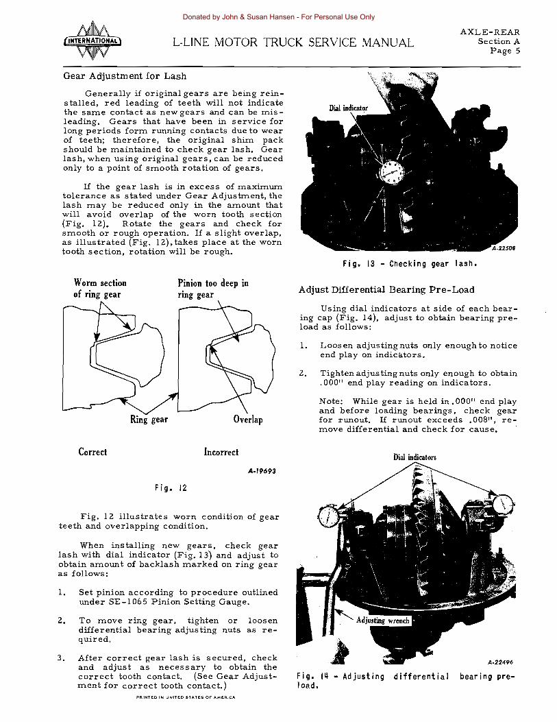

AXLE-REAR Section AL-UNE MOTOR TRUCK SERVICE MANUAL
Page 7
Preload the pinon bearings by replacing the spacer between the pinon bearings with one smaller to the extent of the amount of the end play plus 002t for the loading For example should there be 005 end playas indicated in the sketch in the assembly replace the spacer with one 001 smaller Do not depend upon the spacers to be right according to number but check each and everyone with an accurate micrometer Before reassembling the bearshyings to the pinion shaft they should be dipped in rear axle lubricant Propeller shaft flange nut must be pulled down securely to assure tight bearings A wrench with 30 11 of leverage should be used
In order to determine if insufficient or excessive preload has been applied make the following te st
(1) Place assembly in vise with jaws clampshying together on the flange of the pinion bearing cage and with assembly in a hori shyzontal position
(2) Grasp the propeller shaft flange with one hand and attempt to turn
(3) If the pinion turns freely assembly is too loose If pinion cannot be turned assemshybly is too tight
(4) The ideal condition is to secure a firm drag when turning the pinion cage by hand
After proper bearing fit has been obtained place pinion bearing cage shims approximately 020 in thickness over end of cage and place cage and pinion assembly in carrier it being necessary to match flange holes in cage since one hole is out of equal spacing to assure propshyer position of cage Next assemble two cage bolts only until gear setting is completed Assemble differential and bevel gear assemshybly and place bearing cap and adjuster in posishytion Tighten bearing cap bolts and back off slightly to provide sufficient Iposeness to allow turning the adjuster for a temporary backlash adjustment of approximately 01 Ot After this adjustment has been made tighten each bearing adjuster snug then give them a final tightening operation drawing them up to secure the 005 to 007 total bearingpre-load This is imshyportant in order to make certain that the bearshyings are seating properly
IMPORTANT Hypoid drive pmlon oil seals must be soft and pliable before being inshystalled if the seals have become dried out and hard while in stock use kerosene and work it in thoroughly When seal has become soft and pliable dip it in hot oil and work this oil in thoroughly
PRNTED IN UNITED STATES or A ME JltIICA
Fig 17 - Using the pinion staking tool
Pinion Bearing (Straddle bearing)
The straddle pinion bearing is held in place on the pinion by a staking operation
The staking operation is accomplished through the use of a hydraulic or screw press applying 18 to 20 tons pressure on the special staking tool as illustrated in Fig 17 The reshysult will be uniformly spaced ball indentations that securely lock the pinion bearing to the shaft
Differential Ring Gear Rivet Removal
If necessary to remove hypoid ring gear or herringbone gear rivets drill the rivet heads from the gear side using a drill slightly larger than the rivet itself Use a punch for the reshymoval of the remaining portion of the rivet (See Fig 18)
Knocking off or busting rivets is a danshygerous practice both from the standpoint of personal safety and because such practice may cause distortion to the gear carriers or gears and will elongate the rivet holes
Rivet Pressures
Proper installation of differential ring gear rivets demands that sufficient pressure be applied to the rivets to expand them and cause them to completely fill the holes in which they are installed Riveting should be done with COLD rivets Hot rivets will shrink when cool leaving s space and inviting shearing upon the application of torque
A-22727
Donated by John amp Susan Hansen - For Personal Use Only
AXLE-REAR Section A L-UNE MOTOR TRUCK SERVICE MANUALPage 8
Difierential case
A-22831
Fig 18 - Drill rivet head and punch-out rivet as shown
Riveting Jig SE-1575 is available and is designed for use with hydraulic or ITlechanical press equipITlent
The following pressures are recoITlITlended for differential ring gear rivet installation
PRESSURE RIVET SIZE PER RIVET
(INCH) (TONS)
516 12 to 15 38 17 to 20 716 30 to 35 12 45 to 50 916 60 to 70 58 60 to 70
Axle Shaft Removal (Timken Axles)
Axle shafts are attached to the wheel hubs by studs and nuts at the flanged ene Stud holes in each axle shaft flange are taper-reaITled to receive split tapered dowels
When disasseITlbling the axle SOITle of the bearing cage studs or axle shaft studs ITlay turn loose froITl the housing rather than at the nuts When the axle is reasseITlbled the nuts should be reITloved froITl the studs and the studs reshyplaced in their tapped holes before installing the cage or carrier
When reITloving the axle shafts froITl the Tirnken axle reITlove the stud nuts and lockshywashers and proceed as indicated in Figs 19 20 21
Aloon
Fig 19 - Using a heavy hammer strike sharply on the center of the flange of the axle shaft This wi II unseat and loosen the tapered dowels in each stud hole
Fig 20 - Remove the tapered dowels Note When reassembling there must be a sl ight clearance between the lockwasher and axle shaft driving flange Excessive wear onstuds dowels or holes in the flange wi 11 indicate a lack of clearance at this point
Donated by John amp Susan Hansen - For Personal Use Only
9
AXLE-REAR Section AL-UNE MOTOR TRUCK SERVICE MANUAL
Cap Spring
Valve body
Rear axle breather valve
Location of breather valve on heavy duty axles
Fig 21 - Push the axle shaft flange back into position against the wheel hub and again strike a sharp blow in the center of the axle shaft flange This will cause thi axle shaft to spring away from the wheel hub and allow reshymoval of the axle shaft without resorting to the use of a pry bar or screwdriver Do not pry between the axle shaft flange and wheel hub To do so is apt to damage the seal asshysembly or machined surfaces of the wheel hub or axle shaft flange
When reinstalling the axle shafts the re must be a slight clearance between the lockwashers and driving see Fig 20 Excessive wear on studs dowels or hole s in the axle flange will take place when no clearance exists
Axle Housing Breather Valve
When the rear axle becomes warm after a short period of operation a pressure is built inside the axle housing To prevent this presshysure from forcing lubricant past the rear wheel oil seals and damaging the brake linings a breather valve has been provided The valve is so constructed that warm air may pass out of the axle to relieve built up pressure yet dirt and moisture are prevented from entering The location of the breather valve is shown in Fig 18 inset shows detail of valve
The breather valve should be kept open and clean When the vehicle is operated or unshyimproved highways or in ice and snow it is possible that dirt will be forced under the valve cap thus rendering the valve ineffective Reshymove valve occasionally and clean thoroughly in a cleaning solution
NOTE Where power divider is mounted on rear axle the breather is mounted on upper side of the power divider
PRINTEO IN UNITEO STATES OF AMERICA
Fig 22 - Keep breather valves clean and free of obstruction Breathers are usually located in housing as illustrated
IMPORTANT
Lubrication Of Hypoid Axles
The lubricant used in hypoid axles is an important factor in obtaining long gear life and satisfactory drive unit service Past experishyence proves that a large portion of service problems can be traced to using incorrect or lubricant of poor quality
In the selection of Hypoid Lubricants it is advisable to consider using products of unquesshytionable quality
Because of the higher unit pressures and sliding tooth characteristics of hypoid gearing the lubricant must have properties which enshyable it to withstand these actions
It is important that the axle hypoid gearing receive initial lubrication after overhaul or when a vehicle has been standing in storage and BEFORE THE AXLE IS SUBJECTED TO HEAVY LOADS Good practice is to check the lubricant level in the axle housing then JACK UP BOTH rear wheels and operate the vehicle in high transmission gear at approximately 25 miles per hour for five minutes This will assure thorough lubrication of the gearing beshyfore the unit is placed into service (Do not allow one wheel to race faster than the opposite wheel)
Where the axle pinion cage is provided with a plug at the pinion cage insert one pint of lubricant to provide initial lubrication for the pinion bearing
Donated by John amp Susan Hansen - For Personal Use Only
AXLE-REAR Section A L-UNE MOTOR TRUCK SERVICE MANUAL Page 10
Specified Lubricant For Hypoid Axles
For hypoid axles (not Eaton) use SeL EP gear oil or a multi-purpose gear lubricant suit shyable for hypoid axles and supplied by a reputashyblerefinery SAE-90for cold climate and SAEshy140 for warm climate For Eaton hypoid axle use a hypoid gear lubricant available as Elco Gear Safety 1281 or its equivalent A number of hypoid lubricantes are prepared by reputable companies which contain Elco additive concenshytrates (See Lubricationlf
section A)
NOTE When reassembling the differential gears thrust washers cross shaft spur gears and bearings lubricate the wearing surfaces with a light coat of the specified axle lubricant
Differential Assembly -- L-110 and L-120
The L-110 and L-120 Series Trucks use differential assemblies that are identical in construction except that a spacer or thrust block is used when the unit is installed in a L-110 axle
Since the L-110 axle is of semi-floating construction a means of taking up the end thrust of the axles and wheels must be proshyvided The block serves this purpose The wheel bearings pick up the end play or thrust on the L-120 (full-floating) axles and no thrust block is needed Also the axle shafts in the full-floating design are slightly longer than those used in the semi-floating design and for this reason the thrust block must be removed when the differential unit is used in the L-120 series vehicle
Removal of the thrust block is as follows
1 Drive cross pin retainer pin from differshyential case so as to clear the cross pin (Fig 23)
2 Using punch drive the cross pin out of differential case far enough to remove the thrust blocks (Fig 24)
Retainer
Fig 2
3 Push cross pin back into position in the differential case Drive retainer pin into position and stake case to secure retainer pins (Fig 25)
Stake the case to secure
retainer pin
Fig 25
Amiddot2J436
Fig 23 - Driving retainer pin from differenshytial case using a hammer and punch
Donated by John amp Susan Hansen - For Personal Use Only
AXLE-REAR Section ALmiddotLJNE MOTOR TRUCK SERVICE MANUAL
Page 11
SINGLE-REDUCTION HYPOID AXLE (UNIT SHOWN IS MODEL R-1060 OR R-1070)
1 2 3 4 5 6 7 8 9
10 11 12 13 14
Fig 26 - Sectional Companion flange Propeller shaft mounting nut Propeller shaft mounting nut washer Pinion shaft bearing oil seal Pinion bearing cage to carrier capscrew Pinion bearing cage Pinion bearing outer Pinion bearing Pinion bearing Hypoid pinion gear (straddle mounting) Pinion bearing Difpounde rential side gear Axle housing Differential bearing adjuster lock
Amiddot22643
View of Hypoid Rear Axle IS Differential cross pin 16 Hypoid ring gear 17 Hypoid ring gear rivet 18 Diffe rential pinion 19 Axle shaft 20 Differential bearing adjuster 21 Differential carrier to housing gasket 22 Differential carrier to housing capscrew 23~ Differential roller bearing 24 Differential center block 25 Differential cross pin retaining pin 26 Differential case 27 Differential carrier housing 28 Pinion bearing cage shim
NOTE Rear Axle R-l070 is identical with above description except differential center block (24) is not used
PRINTEO IN UNITEO STATES 0 6MERICA
Donated by John amp Susan Hansen - For Personal Use Only
AXLE-REAR Section A L-UNE MOTOR TRUCK SERVICE MANUAL
12
SINGLE-REDUCTION HYPOID AXLE (MODELS R-1165 R-1170 R-1440 R-1470 R-1530 R-1555 R-1630)
30 29 28 27 26 25 24 23 22 21---l
------6 7 8 9
Fig 27 - Sectional
1 Axle housing 2 Hypoid ring gear 3 Differential bearing cap 4 Differential bearing cap mounting stud 5 Differential bearing 6 Differential bearing adjuster 7 Oil pascage to pinion bearings 8 Pinion bearing cage shims 9 Pinion bearing cage
10 Pinion oil seal retainer 11 Pinion oil seal 12 Slinger 13 Companion flange 14 Thrust washer 15 Propeller shaft companion flange nut 16 Pinion cage mounting capscrew 17 Differential carrier mounting capscrew 18 Pinion bearing cage cork seal 19 Thrust washers
View of Hypoid Rear Axle
20 Pinion bearing outer 21 Pinion bearing spacer 22 Pinion bearing inner 23 Hypoid pinion (straddle mounting) 24 Pinion bearing 25 Differential case bolt lockwire 26 Differential case bolt 27 Differential carrier 28 Differential carrier mounting gasket 29 Axle shaft 30 Diffe rential bearing adjuste r lock 31 Differential side gear thrust washe r 32 Differential case plain half 33 Differential side gear 34 Differential spider pinion 35 Differential spider pinion thrust washer 36 Differential spider 37 Differential case flanged half
Donated by John amp Susan Hansen - For Personal Use Only
AXLE-REAR Section BL-UNE MOTOR TRUCK SERVICE MANUAL
Page 1
TWO-SPEED AXLES SEE SECTION Hit FOR ELECTRIC SHIFT
A2UI4
Fi g I - Two-Speed Axle (Eaton)
1 Hypoid ring gear 17 Bearing inner 33 Axle shaft 2 Oil collector drum 18 Hypoid pinion 34 Bearing adjuster lock 3 Ring gear case 19 Bearing spacer 35 Bearing adjuster 4 Thrust washer 20 Bearing outer 36 Bearing cap 5 Bearing cap stud 21 Companion flange 37 Thrust washer 6 Bearing cap 22 Washer 38 Side gear thrust 7 Carrier bearing 23 Nut washer 8 Clutch plate 24 Cage capscrew 39 Side gear 9 Sliding clutch 25 Slinger 40 Differential pinion
lO Shift fork 26 Seal 41 Pinion thrust washer 11 Shift fork shaft 27 Washer 42 Differential case 12 Clutch plate 28 Pinion cage 43 Pinion gear spider 13 Sliding clutch 29 Shims 44 Ring gear case 14 Diaphragm seal 30 Carrier 45 Idler pinion pin 15 Gear case bolt 31 Carrier capscrew 46 Idler pinion gear 16 Shifter motor stud 32 Gasket 47 Axle housing
PRINTED IN UNITED STATES OF AMERICA
Donated by John amp Susan Hansen - For Personal Use Only
AXLE-REAR Section B L-LlNE MOTOR TRUCK SERVICE MANUAL Page 2
EATON TWO-SPEED REAR AXLE
The two-speed rear axles are full-floating hypoid drive type having four planetary gears which mesh with an internal gear on the hypoid ring gear
The primary reduction is accomplished through the hypoid ring gear and a straddleshymounted hypoid pinion The secondary reducshytion is accomplished with a sliding clutch serving to lock or unlock the planetary gears
Serving
The correct servlcmg of this unit as is true with any mechanical equipment is imporshytant to satisfactory operation and life Servicshying the two-speed unit does not require special tools The ordinary equipment found in most shops is sufficient for this work Use the folshylowing step-by-step procedure for disassemshybling Direct reversal of the action will be the proper reassembly procedure (See Shop Talk No 1 for step-by-step illustrations on disasshysembly)
Disassembly
Remove differential carrier assembly complete from the truck following the same procedure as you would to take out a single or double reduction unit except in this case the two wires on the shift unit must be disconshynected For convenience in handling the head maybe placed in the end of a clean small drum The opening should be large enough to accept the bevel drive gear and bearing caps Then proceed as follows
1 Remove the two shift housing to carrier stud nuts and lockwashers and pull off shift unit assembly (See section IIH for electric shift instructions)
2 Remove plug washer spring capscrew lockwasher and oil distributor
3 Pull out shift fo rk shaft aite r removing shift fork shaft retainer (Fig 2) The shift fork may then be slipped from the sliding clutch gear and removed through the back of the differential carrier
4 Slip out sliding ~lutch gear
5 Mark right hand differential bearing adshyjuster with punch (This is for relocating when reassembling)
6 Remove bearing cap bolt lockwires on both right and left hand sides Loosen cap bolts only Take off right hand bearing adjuster lock and cotter pin
7 Remove left hand differential bearing cap adjuster and lock as an assembly to assure
correct positioning of gear on reassembly (When reassembling hold adjuster and bearing cap up away from threads in bore of carrier unit cap bolts are started Drop cap the threads of the adjuster and those in carrier will mesh freely)
8 After removing bearing caps tip up left hand end of planetary unit and lift out
9 Remove pinion bearing cage capscrews
10 Using a suitable puller remove pinion assembly from carrier May also be reshymoved by using a brass drift and tapping lightly from the inside (Note shims under pinion bearing cage)
I L Remove pinion shaft nut and slide off comshypanion flange
12 Lift off pinion bearing cage bearing washer and spacer
13 Drive off pinion bearing cage by tapping lightly between teeth of pinion alternately on opposite sides of inner race CA UTION Exercise care so as not to damage bearing during this operation
12 Remove pinion bearing cone and washer cage assembly Take out pinion bearing cage cork (Replace this cork with every repair)
15 Remove lockwires nuts and bolts from planetary unit (support case)
16 Tap alternately on opposite sides of ring gear with head of rawhide hammer until gear is free of Hange on support cas e (When reassembling use two bolts to asshysure proper alignment of bolt holes)
17 Lift off left hand support case and bevel drive gear
lH Pry off high speed clutch plate and take out idler pinions and pins
19 Lift out entire differential asseITlbly and remove support case thrust washer
20 Take out differential case bolt lockwire and remove bolts (Note short bolts beshytween spider arms)
21 Lift off right hand differential case Pick up long hub side gear right hand and slip off thrust washer (Note-chamfered side of washer agains t back face of gear)
22 Pull out spider and di[feren tial s ide pinshyions noting thrus t washers behind pinions Slip washers and pinions off spider arms Take out short hub side gear left hand
Donated by John amp Susan Hansen - For Personal Use Only
AXLE-REAR Section BL-UNE MOTOR TRUCK SERVICE MANUAL
Page 3
and remove thrust washer (Note chamshy Gear Tooth Contact fered side of washer against back face of gear )
23 Remove differential bearing cones by striking inner race on alternate sides through holes provided in the support case
24 In reassembling the pinion use SE-I065 pinion setting gauge in adjusting matched sets of pinions and ring gears to proper cone settings (Theoretical cone centers for various axles are found under Specifi shycations Rear Axle Section)
REASSEMBLY -- IMPORTANT
Assembling Differential Unit Lubricate both sides of all thrust washers
well Chamfered sides of washers must be against back face of side gears Lubricate spider arms side-pinion bores and side-gear hubs Draw bolts tight with long-handled wrench and securely fasten with lockwire
Assembling Planetary Unit Before placing thrust washer lubricate
both sides well Cover idler-pinion pins with lubricant Chamfered teeth on high-speed clutch plate must face pinions Place notches in oil-collector drum between bolt holes in bevel gear Draw bolts tight with long-handled wrench and secure wire
Pinion Shaft Bearing Adjustment Desired bearing tension is obtained by usshy
ing a spacer of the correct thickness between the bearing inner races There are 12 spacers each of different thickness available for this purpose To make the assembly proceed as follows 1 Place the pinion and bearings in position
in the cage using original spacer providshying the pinion did not have any perceptible end movement before disassembly
2 Then assemble flange washer and flange Tighten retaining nut securely There should be no perceptible end play and bearshying should roll freely If correction is to be made select proper size spacer to obshytain desired fit
Assembling Differential Carrier Unit Lubricate all bearings as they are assemshy
bled in carrier After adjusting gear be sure cap bolts are tight Wire bolts securely inshycluding capscrews in adjuster lock
Pinion Bearing Pre-Load Follow instructions given in Hypoid Rear
Axle Section HAll page 6
Differential Carrier Bearing Pre-Load
The correct procedure for securing the specified carrier bearing pre-load as listed in the Rear Axle Specification for these axles will be found in Section All Hypoid Rear Axles
PRINTED IN UNITED STATES or AMERIG
To secure best possible tooth contact use SE-I065 pinion setting gauge and follow inshystructions under this heading Section A page 2 Check results obtained by making a paint impression test of tooth contact See Gear Adjustment for correct tooth contact - Paint Impression Method Section A page 3
Lubrication
An oiling system is provided to supply lushybricant within a half a turn of the truck wheels to the essential places during conditions when splash and dip alone would be insufficient A heavy coating of oil is picked up by the oil collector drum and transmitted to the oil scoop The oil scoop scrapes the oil from the drum and splits it into two courses One half of this lubricant goes to the pinion bearings the other half to the right hand differential and planetary unit to the left differential bearing and then returning to the reservoir
Whenever a two-speed differential (new or rebuilt) has been installed in the axle housing fill the oil reservoir to bottom of filler plug opening and replace plug Then add one addishytional pint of lubricant using filler hole provided at top of carrier housing just above pinion cage
Use a hypoid gear lubricant available as ElcoGear Safety 1t28lt or its equivalent Anumshyber of hypoid lubricants are prepared by repushytable companies which contain Elco additive concentrates Viscosity of the hypoidlubricant should be SAE-90 When high atmospheric temshyperatures (above 1000 F) prevail SAE-140 may be used See Lubrication section A
Fig 2
Donated by John amp Susan Hansen - For Personal Use Only
Donated by John amp Susan Hansen - For Personal Use Only
AXLE-REAR Section CL-UNE MOTOR TRUCK SERVICE MANUAL
Page 1
1 2 3 4 5 6 7 8 9
10 11 12 13 14 15 16
DOUBLE-REDUCTION AXLE (EATON)
~4i------
Carrier gasket Carrier Herringbone gear Gear rivet Oil distributor disc Case flanged half Case bolt and nut Thrust washe r Bearing cap Cap stud Lock ring Bearing Side gear Thrust washer Lock ring Oil scoop
PRINTED IN UNTEO STATES or- AMpoundRICA
Fig I shy
17 18 19 20 21 22 23 24 25 26 27 28 29 30 3l 32
Double-Reduction Axle (Eaton)
Spring and plug Axle shaft Counte r shaft bearing Pinion countersh3it Cage capscrew Bearing cage Carrier capscrew Cage shiITls Oil reservoir Hypoid pinion Bearing inner Bearing spacer Bearing outer Washer Slinger Companion flange
33 34 35 36 37 38 39 40 4l 42 43 44 45 46 47 48
13 14 15 16 17 18 19
20
A22813
Cotter pin Nut Washer Oil seal Bearing cage Cage shims Oil passage Hypoid ring gear Oil distributor disc Oil scoop Oil scoop capscrew Spider pinion Pinion thrust washer Case plain half Spider Axle housing
Donated by John amp Susan Hansen - For Personal Use Only
AXLE-REAR Section C L-UNE MOTOR TRUCK SERVICE MANUAL Page 2
EATON DOUBLE-REDUCTION REAR AXLE
The Eaton double-reduction rear axles shown in Fig 1 are heavy-duty double reducshytion type The primary reduction is through a hypoid ring and pinion gear while the secondary reduction is through a set of herringbone gears
Primary Reduction
The primary reduction gears are the hyshypoid type consisting of a hypoid pinion mounted on the forward end of the carrier housing and meshed with a hypoid ring gear which is riveted to an integral flange on the ring geariii shaft This shaft also carries as an integral part the herringbone drive pinion for the secondary reduction
Secondary Reduction
The secondary herringbone reduction gears consist of a drive pinion and a mating gear The teeth on the secondary reduction gears are right and left-hand spiral cut in line with each other forming a VI the apex of which is at the center of the gear face A center cut through the apex breaks the tooth line into two separate and opposed spiral gears each exert shying equal and opposed pressure thus balancing thE end thrust
Installing New Herringbone Drive Gear (Differential Case)
If new gears are being ins taIled the pilot diameter on differential case drive gear flange should be checked to see that it runs true If inspections indicate a run out of 004 a new differential case should be installed When assembling drive gear on face of flange make sure each rivet is tight The best results are obtained if a press is used to install rivets Follow the instructions outlined under Rivet Pressures on page 8 Section At
Hypoid Pinion Shaft and Adjustment
Adjustable hypoid pinion bearings are assembled to pInIOn shaft and retained by universal joint flange and nut on forward end of pinion shaft
A spacer (available in several thicknesses) is used to maintain correct distance between front and rear bearings and to secure the pinshyion bearings pre-load as indicated in Rear Axle Specifications The pinion cage is mounted in the conventional manner and the correct cone center adjustrnent is secured by means of a shim pack under pinion cage flange See SE-l065 Pinion Setting Gauge Section A page 2)
IMPORTANT Hypoid drive pinion oil seals must be soft and pliable before being inshystalled if the seLls have become dried out and hard while in stock use kerosene and work it in thoroughly When seal has become soft and pliable dip it in hot oil and work this oil in thoroughly
Pinion Bearing Lubrication
NOTE When reassembling differential to axle housing or new and dry differential is used from stock be sure to inject about one pint of differential lubricant into the pinion bearing housing through the filler plug opening at the side of the carrier This will provide immediate lubrication for the pinion bearings upon placing the unit in operation
Herringbone Gear Shaft (Cross Shaft)
The herringbone drive pinion gear shaft is mounted at right angles to the hypoid pinion shaft in the carrier housing This shaft is a one-piece steelpoundorging consisting of an integral herringbone gear in the center and an integral flange on one end to which is bolted a hypoid ring gear
To remove this shaft it is necessary to remove the differential and herringbone ring gear assembly Then withdraw the hypoid pinshyion and cage assembly far enough to clear the hypoid ring gear when being removed (Reshymoval of universal joint flange is unnecessary) Remove both bearing covers and using a soft hammer tap ring gear end of shaft until the bearing cup at opposite end of shaft is removed from carrier housing This will permit suffi shycient opening to partly pass shaft through until bearing is clear of carrier housing at ring gear end of shaft Tilt ring gear end of shaft to rear and withdraw from carrier
The cros s shaft bearing covers control the hypoid pinion and ring gear backlash and tooth contact as well as the bearing pre-load This is accomplished by means of a shim pack under each bearing cover
Herringbone Gear Adjustment
Herringbone gears are not adjustable for backlash This clearance is taken into account in the construction and remains constant as long as the gears remain undamaged or the differshyential carrier bearings are not worn excessiveshyly
The self-aligning differential carrier bearshyings eliminate the need for adjustment to align the herringbone pinion and herringbone ring gear The heavy duty roller bearings permit
Donated by John amp Susan Hansen - For Personal Use Only
AXLE-REAR Section CL-LINE MOTOR TRUCK SERVICE MANUAL
Page 3
the differential carrier to move sidewise within the bearing race sufficiently to keep both gears in perfect alignment at all times
Differential
Differential is convential four-pinion type with thrust washers back of side gears and pinshyions Cases are supported on heavy duty roller bearings
Differential Lubricators
The double reduction axles have special provision incorporated to supply oil to the hershyringbone pinion shaft bearings as well as the hypoid pinion shaft bearings This is accomshyplished by scooping lubricant from oil collector discs mounted on the herringbone gear and the hypoid ring gear The lubricant is picked up from these discs by oil scoops and circulated through special passages to the differential carshyrier bearings and the herringbone pinion shaft bearings Fig 2 illustrate s the flow of oil and the principal of this means of bearing lubricashytion
5
Fig 2
Lubrication of Hypoid Axles
The lubricant used in hypoid axles is an important factor in obtaining long gear life and satisfactory drive unit service Past experishyence proves that a large portion of service problems can be traced to using incorrect or lubricant of poor quality
In the selection of Hypoid Lubricants it is advisable to consider using products of unquesshytionable quality
Because of the higher unit pressures and sliding tooth characteristics of hypoid gearing the lubricant must have properties which enshyable it to withstand these actions
It is important that the axle hypoid gearing receive initial lubrication after overhaul or when a vehicle has been standing in storage and BEFORE THE AXLE IS SUBJECTED TO HEAVY LOADS Good practice is to check the lubricant level in the axle housing then jack UP BOTH rear wheels and operate the vehicle in high transmission gear at approximately 25 miles per hour for five minutes This will asshysure thorough lubrication of the gearing before the unit is placed into service (Do not allow one wheel to race faster than the opposite wheel)
Where the axle plmon cage is provided with a plug at the pinion cage insert one pint of lubricant to provide initial lubrication for the pinion bearings
NOTE When reassembling the differential gears thrust washers cross shaft spur gears and bearings lubricate the wearing surfaces with a light coat of the specified axle lubricant This will help provide initial lubrication
Use a hypoid gear lubricant available as ElcoGear Safety filS or its equivalent A numshyber of hypoid lubricants are prepared by repushytable companies which contain Elco additive concentrates Viscosity of the hypoid lubricant should be SAE - 90 When high atmospheric temshyperatures above 100 F) prevail SAE-I40 may be used
PRINTO IN UNITpoundO STATpoundS 01 AMERICA
Donated by John amp Susan Hansen - For Personal Use Only
Donated by John amp Susan Hansen - For Personal Use Only
AXLE-REAR Section DL-UNE MOTOR TRUCK SERVICE MANUAL
Page 1
SINGLE-REDUCTION AXLE (TIMKEN 100 SERIES AXLES)
Fig I - Single-Reduction Timken 100 Series Axle
1 Pinion shaft nut 19 Adjusting nut lock 2 Pinion shaft nut washer 20 Differential bearing cap 3 Companion flange or yoke 21 Side gear thrust washer 4 Oil seal 22 Side gear 5 Thrust washer 23 Pinion thrust washer 6 Pinion bearing outer 24 Pinion bushing 7 Pinion bearing spacers 25 Differential spider 8 Cover gasket 26 Pinion gear 9 Bearing cover 27 Bevel drive gear
10 Pinion bearing cage shims 28 Rivet 11 Pinion bearing inner 29 Differential pan bolt long 12 Pinion 30 Differential case 13 Lubricant filler plug 31 Differential case bolt short 14 Pinion radial bearing 32 Thrust block adjusting screw 15 Breather 33 Lock nut 16 Differential side bearing 34 Thrust block 17 Adjusting nut (differential) 35 Differential carrier 18 Axle shaft 36 Pinion bearing cage
37 Slinger PAINTEO IN UNITEO STATES OF AMEFfle
Donated by John amp Susan Hansen - For Personal Use Only
AXLE-REAR Section D L-LINE MOTOR TRUCK SERVICE MANUAL Page 2
TIMKEN SINGLE-REDUCTION AXLES
Description
The Timken Single-Reduction Rear Axle (R-IOO) is a full-floating hypoid-type final drive assembled in a one-piece axle housing
The differential used in the R-lOO Timken Single-Reduction Axle is of four-pinion-type with thrust washers used between the pinions and case The pinions contain bushings which can be renewed when necessary Thrust washshyers are also used between the side gears and case The two halves of the differential case are machined as a complete assembly and must be replaced as such
Removal of Differential Carrier - Hypoid
To remove the differential carrier assemshybly remove plug from bottom of axle housing and drain out the lubricant Disconnect the propeller shaft atfront end of pinion shaft Be sure to replace the universal joint trunnions on their respective journals and hold them in place with a short loop of wire until ready to reassemble Remove axle shafts and differshyential carrier to housing capscrews or stud nuts on heavy-duty axles and take out carrier
When removing the differential from the axle housing it will be necessary to utilize the two puller screws to loosen the differential carrier as shown in Fig 2
The differential thrust block screw shown in Figs 3 amp 4 must be removed before the difshyferential can be removed from the carrier
Differential
The differential assembly of this axle conshysists of four nine-tooth pinions mounted on a spider and two 16 tooth side gears all assemshybled into the differential case -- One half being flanged to mount the hypoid ring gea r
Hardened steel thrust washers are installed between the side and the case and between the pinions and case The differential case is held together by twelve bolts eight of which are longe r than the remaining four
Differential Disassembly
Mark each half of the differential case before teardown so tnat they can be reassemshybled in the original position Wash and inspect all parts and replace any which are at all questionable Oil all parts with gear oil before reassembly Use new lockwashers when reshyassembling
Fig 2 - Loosen lock nuts on two puller screws provided and turn pul Jer screws down into carshyrier It may bemiddot necessary to break carrier loose from housing by striking the carrier with a heavy soft hammer (lead or leather)
Fig 3 - Place differential carrier in suitable holding fixture or overhaul stand and loosen the lock nut on the drive gear thrust block adshyjusting screw Remove thrust block adjusting screw from carrier This wil I permit the thrust block to fall into the carrier
Rotate gear to Ibring holein block iIi line with adjusting
Fig ~ - When replacing thrust block place block on gear and rotate gear to bring block in line with adjusting screw
Donated by John amp Susan Hansen - For Personal Use Only
AXLE-REAR Section DL-UNE MOTOR TRUCK SERVICE MANUAL
Fig 5 - If it is necessary to remove the ring gear from the differential case half carefully center punch each rivet in the center of the rivet-formed head as shown Dril~ through the center of each rivet-formed head using a dril I sl ightly larger than the body of the rivet Punch or press rivet out of gear and case half
If inspection reveals that the ring gear should be replaced exercise care when removshying the ring gear rivets Fig 5 shows the correct way to remove the ring gear rivets to avoid damage to the differential case
The four differential spider pmlOn gears run on bronze bushings and where they are found to be worn excessively the bushings can be replaced Cut the old bushings out of the pinions and using the special tool shown in Fig 6 install and burnish the new bushings in the pinions
Bronze bushings are burnished by means of a stud ball which when being pressed through the pinion bushings compresses the bushing metal giving a denser surface and tighter fit in the pinion The burnishing operation also locks the bushings in place in the pinion since some of the bushing metal is compressed into the locking groove located on the inside bore of the pinion The correct size ball should be ap proximately 005 11 larger than the spider trunshynion Do not attempt to ream the spider pinion bushings
Pinion
The pmlOn cage can easily be withdrawn from the differential carrier with the use of puller screws provided
PRINTED IN UN1TpoundO STATES OF AMERICA
Page 3
Press
Preas burnishiDg ball thro~b bushiDg
Fig 6 - Use bar to press burnishing ball through bushing The correct size bal I should be approximately 005 larger than the differshyential spider trunnion
Remove the pinion shaft from the pinion cage on a press Remove the inner pmlOn bearing with a suitable puller The inner radial bearing retainer is removed after removal of the retainer screw
Pinion Bearing Pre-Load
When the pinion shaft bearings bearing spacers and pinion cage have been reassembled
Fig 7 - Checking pinion bearing pre-load using torque method
Donated by John amp Susan Hansen - For Personal Use Only
AXLE-REAR Section D L-UNE MOTOR TRUCK SERVICE MANUAL Page 4
be sure to check the bearing pre-load Attach a scale to the end of a soft wire wrapped around the pinion cage as in Fig 7 Read the scale only when pinion cage is moving (rotating torque) If first adjustment does not result in correct pre-load select a thicker combinashytion of spacers to decrease or use thinner combinations of spacers to increase the bearing pre-load The rear axle specifications list the correct bearing pre-load for these axles
Gear Adjustment for Correct Tooth Contact
Checking tooth contact is accomplished by means of oiled red lead applied lightly to the bevel gear teeth When the pinion is rotated the red lead is squeezed away by the contact of the teeth leaving bare areas the exact size shape and location of the contacts
Gear Adjustment for Lash
Generally if original gears are being reshyinstalled red leading of teeth will not indicate the same contact as new gears and can be misshyleading Gears that have been in service for long periods form running contacts due to wear of teeth therefore the original shimpack should be maintained to check gear lash Gear lash when using original gears can be reduced only to a point of smooth rotation of gears
If the gear lash in in excess of maximum tolerance as stated under gear adjustment the lash may be reduced only in the amount that will avoid overlap of the worn tooth section Rotate the gears and check for smooth or rough operation If a slight overlap takes place at the worn tooth section rotation will be rough
When installing new gears check gear lash with dial indicator (Fig 8) and adjust to obtain 00611 to 01211 lash as follows
1 To move pinion toward gear remove shims from pack under pinion cage
2 To move pinion away from gear add shims under pinion cage
3 Tomove geartightenor loosendiHerential bearing adjusting nuts as required
After correct gear lash is secured check and adjust as necessary to obtain the correct tooth contact (See gear Adjustmentfor correct tooth contact)
Adjust Differential Bearing Pre-Load
Using dial indicator at back face of ring gear (Fig 9) adjust to obtain bearing pre-load as follows
1 Loosen adjusting nut on side opposite gear teeth only enough to notice end play on inshydicator
2 Tighten same adjusting nut only enough to obtain 00011 end play reading on indicator
NOTE While gear is held in 000 end play and before loading bearings check gear for runout If runout exceeds 008 11 remove differential and check for cause
Fig 9 - Adjusting differential bearing preshyFig 8 - Checking gear lash load
Donated by John amp Susan Hansen - For Personal Use Only
AXLE-REAR Section DL-UNE MOTOR TRUCK SERVICE MANUAL
Page 5
3 Tighten BOTH adjusting nuts one notch each from 000 and play to pre-loaddifferential bearings
4 Tighten bearing cap stud nuts to specified torque (L-lOOand R-100 Axle) (RearAxle Specifications)
5 Install adjusting nut locks capscrews and lock wires
Thrust Block Installation
Turn carrier assembly to bring back face of ring gear facing upward and install the thrust block as follows
1 Place thrust block on rear face of gear and rotate gear until hole in thrust block is aligned with the adjusting screw hole NOTE A light coating of grease placed On the thrust block face will serve to hold the block in position on the rear face of the gear
Fig 10 - Adjusting clearance of thrust block Turn adjusting screw out of carrier Iq turn to obtain 010 to 015 inch clearance
2 Install adjusting screw and lock nut Tightshyen adjusting screw to force thrust block against gear then back off one quarter (14) turn and lock securely with lock nut (Fig 10) Clearance between back face of gear and thrust block is 010 to 015 CAUshyTION Be sure that the adjusting screw end is seated properly in the thrust block hole
Lubrication
1 Remove inspection and oil filler plug (Fig l) and fill to level of plug hole with specshyified lubricant Capacity for the R-lOO axle is 30 pints (30lbs) Capacity of the L-lOO axle is 23 pints (23 lbs)
2 Jack up BOTH rear wheels and operate vehicle in high transmission gear at apshyproximately 25 miles per hour for five minutes to assure proper lubrication of all parts before the Unit is put into service
Both wheels should rotate at approximately the same speed while the vehicle is jacked up Do not allow one wheel to race faster than the opposite wheel To do so might cause serious damage to the differential spider and gears
Use SCL EP gear oil or a multi-purpose gear lubricant suitable for hypoid axles and supplied by a reputable refinery SAE-90 for cold climate and SAE-140 for warm climate
PRINTED IN UNITED STATES OF AMERICA
Donated by John amp Susan Hansen - For Personal Use Only
Donated by John amp Susan Hansen - For Personal Use Only
AXLE-REAR Section EL-UNE MOTOR TRUCK SERVICE MANUAL
Page 1
DOUBLE-REDUCTION TWO- SPEED AXLE (TIMKEN 300 SERIES AXLES)
FAST SPEED HELICAL GEAR
FAST SPEED FREE ROLLiNGVHEN COLLAR
ENGAGES SLOW SPEED PINION
SPACER-SELECTION OF PROPER SPACER GIVES
DESIRED PINION BEARING PRELOAD
SHIFT COLLAR SLIDES ON SPLINED PORTION OF SHAFT ENGAGING DESIRED PINION
SLOW SPEED HELICAL GEAR
SLOW SPEED PINION
CROSS SHAFT ASSEMBLY
AmiddotI579C
Fig I - Two-speed Double-Reduction Drive Unit
Description
The Timken Two-Speed Double-Reduction Final Drive Differential (Fig 7) provides two gear ratios--actually two full size final drives in one unit a fast ratio for maximum speed and a slow ratio for maximum pulling power This feature enables the truck driver to use the proper axle gear combination required for speed load and road conditions
Operation
The first reduction in the Timken TwoshySpeed Double Reduction Drive Axle is through a heavy duty hypoid bevel pinion and gear The hypoid bevel pinion and gear set operates in conjunction with either of two sets of wide-face helical spur gears and pinions of different ratios This second reduction is selective between a fast or slow ratio
The bevel pinion is mounted on two tapered roller bearings in a pinion cage The bevel gear is locked on the cross shaft by a key The cross shaft is mounted on tapered roller bearshyings and carrier two free-rolling helical spur pinions Both spur pinions engage helical spur
PRINTED IN UNITED StATES OF MERICA
gears attached to the tapered roller bearing mounted diffe rential
On the inner side of each of the spur pinions are integral splines On the cross shaft are two rows of splined teeth A shift fork actuated by an electric power shift unit ITIoves the shift collar on the splined portion of the cross shaft to engage the splines on the fast or slow speed spur pinion See Fig 4
When the fast axle speed is selected and torque released the shift collar is moved toshyward the fast speed spur pinion and atthe same time disengages the splines on the slow speed spur pinion The fast speed spur pinion then revolves as part of the cross shaft to drive the fast speed spur gear During this operation the slow speed spur pinion is disengaged so as to rotate freely on the cross shaft Power is transmitted through the hypoid pinion and gear cross shaft clutch collar fast speed spur pinshyion and gear differential and axle shafts
When the slow speed is selected and torque released the shift collar moves in the opposite direction disengaging the fast speed spur pinshyion and locking the slow speed spur pinion as part of the cross shaft Power is then transshymitted through the slow speed spur pinion and gear differential and axle shafts
Donated by John amp Susan Hansen - For Personal Use Only
AXLE-REAR Section E L-LINE MOTOR TRUCK SERVICE MANUAL Page 2
The design of the shift collar prevents disshyengagement until the opposite gear ratio is selected and torque released
Adjustments and Clearances
Various clearance adjustments are proshyvided for both in the axle gearing and shifting mechanism These adjustments once made seldom need attention Where a disassembly job is to be performed the detailed information found in Shop Talk No 34 will be most helpful
Hypoid Pinion and Cage
The pinion and bearings are installed in the pinion cage witha pre-load secured by following the instructions under PinionBearing Pre-Load Sec A The pre-load in controlled by proper selection of spacers or combination of spacers located between the outer pinion bearing and bearing seat on the pinion shaft (Fig 1) These spacers are ground to close tolerances and are available in graduated thicknesses Thicker spacers decrease bearing pre-load and thinner spacer bearing pre-load For correct procedure see pinion bearing adjustment for correct pre-load Sec A
When installing the pinion cage assembly in the differential carrier be sure that the oil passage holes in the carrier housing gasket shim pack and pinion bearing cage are aligned When the original gears are being reinstalled use the original shim pack plus a new gasket under the pinion cage
Hypoid Ring Gear and Cross Shaft
The hypoid ring gear is assembled on the cross shaft by pressing the gear firmly against the cross shaft shoulder (Fig 2) To facilitate
~~~IJjjfii~ 010 MINf
C[EARANC~ 7WHEN~
HypoilYGEAR IS PRESSEDfshy A-GAINSf -fiKSEAT
Fig 2 - Pressing hypoid gear on cross shaft
installation the gear may be heated to 200 to 2500 F Be sure the key is in line with the key slot in the gear before pressing the gear into place
The fast speed pinion located between the hypoid ring gear and splined teeth on the cross shaft should have an end play of at least 010 11
bull
Normal end play will be from 015 minimum to 030 11 maximum The slow speed pinion end play must also check to a minimum of 010 The shift collar is installed over the springs and poppets with the longer splines on the inshyside diameter of the collar toward the hypoid ring gear
The cross shaftbearing pre-load is measshyured by wrapping wire around the slow speed pinion and pulling with a scale to a reading of approximately 8 pounds rotating torque (not starting torque) (Fig 3)
To obtain correct pre-load add or remove shims at shim pack under bearing cage on cross shaft end opposite ring gear Use origishynal shim packs plus a new gasket when reinshystalling original gears
Fig 3 - Checking cross shaft pre-load bull
Gear Tooth Impression and Lash
When the hypoid gear sethas been renewed adjust gear back lash with dial indicator and adjust to obtain 006 to 01211 lash Movement of the gears is controlled as follows
1 To move pinion toward ring gear remove shims from pack unde r pinion cage
2 To move pinion away from ring gear add shims to pack under pinion cage
3 To move ring gear away from pinion reshymove shims from pack under cross shaft bearing cage (side opposite ring gear) and add shims of equal thickness to pack under
Donated by John amp Susan Hansen - For Personal Use Only
AXLE-REAR Section EL-UNE MOTOR TRUCK SERVICE MANUAL
Page 3
cross shaft bearing cage (ring gear side) Shims should be transposed in this manner to maintain the established pre-load
4 To move ring gear toward pinion remove shims from pack under cross shaft bearing cage (ring gear side) and add shims of equal thickness to pack under cross shaft bearshying cage (side opposite ring gear) Shims should be transposed in this manner to maintain the established bearing pre-load
When correct gear lash is obtained check and adjust as necessary to obtain correct tooth contact using oiled red lead applied lightly to the ring gear teeth Gear tooth impression illustrations are shown in Section A pages 3 and 4
Shift Collar Adjustment
The shifting collar serves as the lock beshytween the cross shaft and either the high or the low speed spur pinions When engaged with either speed spur pinion the collar must be flush against the spur pinion face (Fig 4) The collar is held flush against the pinions by three spring loaded poppets located in the cross shaft and unless there is misadjustment in the locashytion or travel of the shifting fork the collar will seat itself against whichever gear is selected
Fig ~ -Checking clearance between shift collar and spur pinion Clearance shoul~ not be less than 010
To check the travel of the collar when the differential is mounted on the axle housing it is necessary to remove the pinion cage assembly Illustrations show details of the checking proshycedure with the carrier removed from the axle housing and the differential gear assembly reshymoved
Check clearance of shift fork collar (flat) faces in shift collar with feeler gauge (Fig 4) The clearance should not be less than 010 minimum on each side of the fork in both the fast and slow speed positions When checking this clearance the shift collar must be flush with the end face of the spur pinion in both fast and slow positions
Shims located at the shifting chamber bracket regulate the travel range of the shift rail and fork Add or remove shims to allow the shift collar to seat flush against the spur pinions in both high and lowpositions (Fig 5 amp 6) The electric shift chamber and bracket assemshybly must be removed from the carrier in order to remove shims
Spring - completes shift when engine torque
is released
I
A-22924
Fig 5 - Details of front mounted electric shifting mechanism Note location of shims for travel adjustment
Electric shift motor
Spring-completes shift when engine torque
is released
Fig 6 - Showing details of side mounted electshyric shift mechanism Shims are provided to adshyjust travel of shift fork Overhaul procedure for the electric shifting unit is given in the Electric Shift Section HR
PRINTED IN UNITED STATES OF AMERICA
Donated by John amp Susan Hansen - For Personal Use Only
AXLE-REAR Section E L-UNE MOTOR TRUCK SERVICE MANUAL Page 4
Fig 7 - Adjusting stop screws to limit travel of shifting fork Fig ~ shows point of contact of the screws with the shifting collar
Adjusting screws located on top of the carshyrier housing (Fig 7) provide means of limiting the travel of the shifting fork and rail Turn in or out on each adjusting screw to stop the travel of the shifting fork so that the fork does not bear against the sides of the shifting collar after the collar is seated flush with the spur pinionface in both high and low positions There must be a minimum of 01 on clearance between the fork and shift collar This clearance is to assure that the collar is free of shifting fork interference and allows the poppets to hold the collar against either qf the spur pinions Also the 01 on minimum clearance is running clearshyance between the forks and collar sides to preshyvent unnecessary wear to the two parts
Differential Adjustment
The differential assembly is installed in the carrier with the helical gears located to provide approximately 11611 clearance between the helical gear sides and shift collar faces in both the fast and slow speed positions Move the differential assembly from side to side to obtain this adjustment by turning on the adjustshying nuts
Using dial indicator at the side face of one of the helical gears adjust to no end play (OOO end play) in the differential bearings Rotate assembly several times to assure normal bearshying contact Tighten adjusting nuts one notch each from 000 end play to secure the correct differential bearing pre-load
With the dial indicator contacting the side face of the helical gear check for runout If runout exceeds 008 remove differential and check for middotcause
Lubrication
1 Before starting new truck and after overshyhaul remove pipe plug at pinion cage and insert one pint of specified lubricant
2 Fill axle housing to correct level with specshyified lubricant Capacity is 18-12 quarts (37 1bs)
3 Jack up BOTH rear wheels and operate vehicle in high transmission gear at apshyproximately 25 miles per hour for five minutes to assure proper lubrication of all parts before the unit is put into service
Both wheels should rotate at approximately the same speed while the vehicle is jacked up Do not allow one wheel to race faster than the opposite wheel To do so might cause serious damage to the differential spider and gears
Use SCL EP gear oil or a multi-purpose gear lubricant suitable for hypoid axles and supplied by a reputable refinery SAE-90 for cold climate and SAE-l40 for warm climate
When reassembling the differential gears thrust washers cross shaft spur gears and bearings lubricate the wearing surfaces with a light coat of specified axle lubricant This will help provide initial lurication
Fig 8 - Insert one pint of lubricant in pinion cage before starting new truck or after overshyhau I
Electric Shift
The electric shift mechanism used on all Tirnken double-reduction two speed axles is identical with the electric shift used on Eaton two speed axles For detailed information see Electric Shift Section H
Donated by John amp Susan Hansen - For Personal Use Only
AXLE-REAR Section FL-UNE MOTOR TRUCK SERVICE MANUAL
Page 1
DOUBLE-REDUCTION AXLE (TlMKEN 200 SERIES AXLES)
(See Shop Talk No 25 for complete illustrated disassembly)
Hypoid gear
Hypoid pinion
Differential case
Helical gear A-I0067
Fig I - Double-Reduction Drive Unit (Timken)
The Timken S-200-P and U-200-P series double-reduction rear axles (Fig 1) introduce improvemen ts in des ign and cons truction over conventional rear axles for on-highway and offshyhighway service in heavy-duty motor trucks
These axles provide increased torque cashypacity and eliminate the former need because of specific chassis requirements for both topshymounted and front-mounted double-reduction final drive units The differential carrier on the S-200-P and U-200-P axles is mounted at an elevation which is a satisfactory comproshymise between the two extremes
The S-200-P and U-200-P rear axles emshyploy the same differential and carrier assemshyblies They differ only in that the rear axle housing of the S-200-P is of lighter construcshytion for the S-200-P axle is not intended for off-highway service
Drive Unit
The drive unit or differential carrier asshysembly is mounted on the sloping front face of the axle housing and is readily removable for periodic inspec tion The differential bearing
legs are dowelled in the axle housing to elimshyinate deflection under torque load
Pinion Shaft Location
The pinion shaft is located at an elevation midway between that used on the front-mounted type axles where the pinion shaft is on the axle center line and that used on the topshymounted type axles where the pinion shaft is considerably above the axle center line (Fig 1)
Final Drive
The final gear-drive consists of a large diameter hypoid bevel gear and bevel pinion for the first reduction and a wide-faced helical gear and helical pinion for the second reduction
A range of gear ratios is available to meet all operating requirements (See Specifi shycations)
Axle Housing
The axle housings in both axles are simishylar in design although the U-200-P axle housshying has larger sections to produce its greater load carrying capacity
PRINTED IN UNITED STATES OF MERICA
Donated by John amp Susan Hansen - For Personal Use Only
AXLE-REAR Section F L-UNE MOTOR TRUCK SERVICE MANUALPage 2
Differential
The differential assembly of this axle conshysists of four 9-tooth pinions mounted on a spishyder and two 16-tooth side gears all assembled into the differential case both halves of which are identical
Hardened-steel thrust washers are inshystalled between the side gears and the case and between the pinions and the case The large helical gear is mounted between the differential case halves and the assembly is held together by twelve rivets The differential assembly is mounted in tapered roller bearings
on Seals 419634
Fig 3 - Illustrates wiper ring and gasketThe rear wheel outer oil seal is illusshy
trated in Fig 2 This is the latest type oil seal assembly and when installing this seal be sure to cement the new cork gasket to the inner flange of the new wiper ring
Fig 11
Axle shaft
Cork gasket cemented to seal wiper AI60f4
Fig 2 - Illustrates installed
sectional view of seal
The seal wiper and cork gasket are pressed over the end of the axle tube Be careshyful not to bend or damage the seal wiper when installing (Fig 3)
The seal retainer assembly is placed over the axle flange studs as shown in Fig 4 using a gasket on both sides of the seal retainer asshysembly
The rear wheel inner seal construction is illustrated in Fig 5 Before installing the inner seal check the location of the bearing and oil seal spacer to be certain that the seal lip on the oil seal assembly faces toward the oil seal wiper ring in the wheel hub as shown
Special adapters should be used in seal installation as described in Service Bulletin B-97-1946 and Addendum No 1 Fig 5 - Rear wheel inner seal
Donated by John amp Susan Hansen - For Personal Use Only
AXLE-REAR Section FL-LINE MOTOR TRUCK SERVICE MANUAL
Page 3
To remove the cross shaft it is necessary to fir st remove the differential and helical ring
Lubrication
1 Before starting new truck and after overshyhaul remove pipe plug at pinion cage and insert one pint of specified lubricant
2 Fill axle housing to correct level with specified lubricant The various axle cashypacities are found in Lubrication Section
3 Jack up BOTH rear wheel and operate veshyhicle in high transmission gear at approxishymately 25 miles per hour for five minutes to assure proper lubrication of all parts before the unit is put into service
Both wheels shOUld rotate at approximately the same speed while the vehicle is jacked up Do not allow one wheel to race faster than the opposite wheel To do so might cause serious damage to the differential spider and gears
Use SeL EP gear oil or a multi-purpose gear lubricant suitable for hypoid axles and supplied by a reputable refinery SAE-90 for cold climate and SAE-l40 for warm climate
Hypoid Pinion and Cage
The pinion and bearings are installed in the pinion cage with a pre-load as indicated in Rear Axle Specifications for these axles The pre-load is controlled by proper selection of spacers or combination of spacers located between the outer pinion bearing and bearing seat on the pinion shaft These spacers are ground to close tolerances and are available in graduated thicknesses Thicker spacers deshycrease bearing pre-load and thinner spacers increase bearing pre-load For correct proshycedure see Pinion Bearing Adjustment for correct pre-load Section A page 6
When installing the pinion cage assembly in the differential carrier be sure that the oil passage holes in the carrier housing gasket shim pack and pinion bearing cage are aligned When the original gears are being reinstalled use the original shim pack plus a new gasket under the pinion cage
Helical Gear Shaft (Cross Shaft)
The helical gear or cross shaft is mounted at right angle s to the hypoid pinion shaft in the carrier housing This shaft is a one -piece steel forging consisting of an integral helical drive pinion gear in the center The hypoid ring gear is aligned with key in shaft before pressing gear onto shaft
PRINTEO IN UNITED STATES OF AMERICA
gear assembly second withdraw the hypoid ring gear when being removed (Do not remove universal joint flange) Then remove both bearing cages move shaft enough to allow bearing at ring gear end of shaft to clear the carrier housing and tilt shaft to rear for reshymoval from carrier
The correct bearing pre-load is obtained by adding or removing shims at shim pack under the cross shaft bearing cage at end opshyposite hypoid ring gear Use orignial shim pack plus a new gasket when reinstalling ori shyginal gears To measure correct bearing preshyload follow method outlined for Timken DoubleshyReduction Two-Speed Axles Section E Fig 3
Donated by John amp Susan Hansen - For Personal Use Only
Donated by John amp Susan Hansen - For Personal Use Only
AXLE-REAR Section GL-L1NE MOTOR TRUCK SERVICE MANUAL
Page 1
TANDEM AXLES
See Legend on following page 8-4745
Fig I - Details of axle mounted power divider mounted on forward rear axle
AXLES--RF-1475 RF-1575 RF-1685 FOUR-WHEEL AXLE-MOUNTED POWER
DIVIDER
The above axles have a power divider built as an integral part of the differential assembly This results in a more simplified tandem axle design with less moving parts The compactshyness of the combined power divider and differshyential makes possible the use of fewer propeller shafts and eliminates the need for a propeller shaft hanger at the rear of the vehicle The
power from the engine is delivered through the transmission (and auxiliary transmission where the truck is so equipped) to the power divider which as the name implies divides the power between the two axles A differential unit is included in the power divider to comshypensate for the difference in speeds between the two axles This difference in axle speeds is brought about by wheels Slipping on either of the axles or slightly different tire diameter due to tire wear (Both rear axles on sixshywheel (6x4) trucks have the same axle differshyential ratio)
PRINTEO IN UNITEO JTTpoundS OF AMERiCA
Donated by John amp Susan Hansen - For Personal Use Only
AXLE-REAR Section G L-LINE MOTOR TRUCK SERVICE MANUAL Page 2
Legend For Fig 1
1 Mainshait 2 Companion flange retaining nut
3 Companion flange 4 Thrust washer
5 Slinger 6 Felt 7 Oil seal B Bearing cover retaining nut 9 Bearing cover
10 Bearing cover gasket 11 Mainshait bearing front 12 Differential lock 13 Transfer case cover 14 Thrust washer 15 Forward axle bevel pinion shaft 16 Pinion bearing cage cover 17 Outer pinion bearing nut lB Pinion bearing cage capscrew 19 Pinion bearing cage cover seal 20 Pinion bearing cage 21 Shims 22 Thrust washer 23 Pinion bearing outer 24 Pinion bearing spacer 25 Pinion bearing inner 26 Spacer 27 Differential spider thrust washers power
divider 2B Transfer case 29 Forward axle helical drive gear 30 Oil seal assembly 31 Pinion bearing 32 Pinion bearing sleeve 33 Pinion bearing sleeve set screw 34 Power divider to differential carrier
mounting capscrew 35 Power divider to differential carrier
mounting gasket 36 Differential carrier 37 Bevel ring gear 38 Differential lubricator 39 Differential lubricator retaining capscrew 40 Differential carrier bearing adjuster 41 Differential carrier mounting capscrew
Rear-rear axle drive shaft outer bearing cover assembly flange nut and thrust washer are identical with the units on outer end of mainshaft
A differential lock is available for the power divider This locking arrangement is used to lock both the front rear and rear rear axles together and is generally us ed when the vehicle is operating in mud snow or off the highway
42 Differential carrier to axle housing mountshying gasket
43 Axle shaft 44 Differential carrier bearing 45 Adjuster lock 46 Differential case bolt and nut 47 Bevel ring gear rivet 48 Differential case flange half 49 Differential spide r 50 Differential spider pinion gear thrust
washer 51 Differential spider pinion gear 52 Differential case plain half 53 Differential side gear thrust washer 54 Differential side gear 55 Axle torque arm 56 Axle housing 57 Rear-rear axle drive shaft companion
flange 58 Rear helical and side gear thrust washer 59 Rear helical and side gear 60 Breather 61 Differential case (male) 62 Differential spider 63 Differential case (female) 64 Rear-rear axle helical drive gear 65 Differential case bolts 66 Differential spider pinion gear 67 Front helical and side gear 6B Rear-rear axle helical drive gear 69 Transfer case cover mounting gasket 70 Transfer case cover 71 Transfer case cover mounting capscrews 72 Thrust washer 73 Drive shaft bearing inner 74 Drive shaft nut inner end 75 Rear-rear axle drive shaft 76 Shifter fork 77 Shift fork bracket mounting gasket 7B Shift fork bracket retaining capsc rew 79 Shift fork lever 80 Shift fork lever boot 81 Shift fork bracket
NOTE Rear-rear axle drive shaft inner bearing (73) and nut (74) are identical with mainshaft inne r bearing and nut
CAUTION The differential must not be held in the locked position longer than necesshysary Driving the vehicle on improved or paved roads with the differential lock engaged will subject the axles and gears to unnecessary strain The differential lock shift fork is spring loaded and automatically releases the lock when shift lever is released by operator
Donated by John amp Susan Hansen - For Personal Use Only
AXLE-REAR Section GL-LINE MOTOR TRUCK SERVICE MANUAL
Page 3
DISASSEMBLY OF POWER DIVIDER (AXLE MOUNTED)
To disasseInble the power divider proceed as outlined in the following steps
1 ReInove nine power divider to differential carrier Inounting capscrews and lift off the power divider Be sure Inounting gasket is also reInoved
2 Place power divider in a transInission stand or other suitable fixture and reInove the four pinion bearing cage Inounting capshyscrews and reInove pinion shaft cover
3 ReInove self-locking setscrew in the transshyfer case to release pinion bearing sleeve
4 ReInove pinion shaft outer bearing nut and using a soft haInIner tap end of shaft to release pinion bearing sleeve and bearing froIn housing Withdraw pinion shaft asshyseInbly froIn transfer case COInplete disshyasseInbly of shaft by reInoving inner pinion bearing spacer front axle helical drjve gear and pinion bearing
5 ReInove pinion bearing cage froIn transfer case
6 ReInove Inainshaft bearing retainer nut inner end
7 ReInove cOInpanion flange mounting nut and using a suitable puller reInove COInshypanion flange and slinger asseInbly
S ReInove four bearing cover capscrews and lift off bearing cover
9 Using a bronze bar drive inner end of Inainshyshaft until shaft passes through rear helical and side gear and thrust washer This gear and washer can now be reInoved through pinion bearing sleeve opening in transfer case
10 Continue pushing mainshaft toward front of transfer case until differential case asshyseInbly and thrust washers are free of shaft Differential case will also pass through pinion bearing sleeve opening in case Mark differential case halves so original asseInbly can be duplicated Keep differential spider thrust washers with differential case to asshysure correct reasseInbly
11 Withdraw Inainshaft all the way Front helical and side gear thrust washer and differential lock (where power diviltler is so equipped) can now be reInoved through pinion bearing sleeve opening
12 Using a suitable puller reInove both front and rear Inainshaft bearings This COInshypletes disasseInbly of Inainshaft
13 ReInove the nine transfer case cover reshytainer screws Carefully reInove cover so as not to daInage cover or gasket face of transfer case as cover Inust be reInoved froIn front bearing of rear rear axle drive shaft
14 ReInove nut at front end of rear rear axle drive shaft The cOInpanionflange at rear of shaft should be used to hold shaft while reInoving nut
15 ReInove COInpanion flange retaining nut and flange at rear of rear rear axle drive shaft ReInove cOInpanion flange with suit shyable puller
16 ReInove the four bearing cover retaining capscrews and reInove bearing cover
17 ReInove bearing at front end of rear rear axle drive shaft using a suitable puller Also reInove helical gear retaining washers
18 Tap front end of rear rear axle drive shaft with a soft haInIner to reInove helical drive gear and spacer This action will also drive the rear bearing out of case so that the shaft Inay now be lifted out
19 Place rear rear axle drive shaft in vice having soft jaws and pull the rear bearing off the shaft
The power divider is now cOInpletely dis asshyseInbled Place all parts in a cleaning solution to reInove all dirt and sludge deposits Be sure transfer case is free of any loose Inetal particles Carefully inspect all parts and replace any that are doubtful as to further satisfactory serviceshyability
To reasseInble the power divider the exact reshyverse procedure as outlined for disasseInbly should be used However it is advisable to observe the following precautions
Be sure all sealing surfaces are free of nicks and that the old gasket Inaterial has been COInshypletely reInoved NOTE The transfer case to differential carrier Inounting gasket is ODS thick
The differential case was Inarked as to forshyward side and also for correct reasseInbly of the two case halves It is of utInost iInportance that the eight differential case Inounting bolts be so installed that the bolt heads are also on forward side of differential asseInbly after installation in power divider NOTE FeInale half of differential case should be forward
PRINTED IN UNiTEO STATES OF ERICA
Donated by John amp Susan Hansen - For Personal Use Only
AXLE-REAR Section G L-LfNE MOTOR TRUCK SERVICE MANUAL Page 4
To secure the pinion bearing pre-load reading specified in the Rear Axle Specifications for this model axle see Pinion Bearing Adjustment for Correct pre-load Make a bench assembly of bevel pinion shaft bearings spacers and pinion bearing cage Place all parts in the same position as in the final assembly The pinion shaft assembly may now be placed in the press shown in Fig 2 After the correct pinion bearshying pre-load reading has been secured remove outer pinion bearing and pinion bearing cage only The pinion shaft is now ready for install shyation Complete assembly of pinion shaft to transfer case by inserting pinion shaft through pinion bearing sleeve opening until sleeve is in correct position Install pinion bearing cage outer pinion bearing thrust washer and nut Do not fail to install pinion bearing sleeve set screw after the cone center and back lash adshyjustments have been made Use a new bearing cage cover oil seal when completing assembly
After the correct pinion bearing pre-load has been obtained mount power divider on differshyential carrier The pinion cone center adjustshyment may now be made Follow procedure set forth under SE-I065 Pinion Setting Gauge Bear in mind the adjustment of the bevel pinion is controlled by means of a shim pack under the pinion bearing cage at forward side of power divider The differential assembly may noW be completed and the bevel ring gear adjusted for back lash -- as marked on outer rim of ring gear Be sure to obtain a tooth contact pattern as outlined under General Rear Axle Hypoid Pinion and Ring Gear Adjustment Point Imshypression Method
The differential carrier and power divider assembly is now complete and ready for inshystallation in forward rear axle housing Use a new differential carrier mounting gasket
Center Cross Bar
The assembly of the center cross bar and saddle is shown in Fig 2 The sleeve is loshycated in the saddle and is locked in place by two thru-bolts Inside the steel sleeve there is a center cross bar which must rotate freely in the sleeve In the LF-l 70 the center cross bar is solid steel and on theLF-190andLF-210 it is a steel tube In removing the tube or cross bar it is first necessary to jack up the rear end of the truck remove the spring shackle pins remove the two equalizer beam end bolts then remove the saddle equalizer beam and the springs The tube or cross bar is then removed from the supporting sleeve
Equalizing Beam Ends
Equalizing beam end construction is shown in Fig 3 The beam end ball is supported in a two-piece bronze socket which is pressed into the beam end Lock bolts prevent the sockets
BUSHING 11-16155
Fig 2
Felt retainer Nut Lockwasber
Felt seal
Lubricato----i~
A-22712
Fig 3
Donated by John amp Susan Hansen - For Personal Use Only
AXLE-REAR Section GLLINE MOTOR TRUCK SERVICE MANUAL
Page 5
from moving and felt seals with spring retainshyers are used to guard against leakage of lubrishycant and entrance of dirt
When replacing a socket or ball assemble both halves of the socket to the ball and press the assembly into the beam end Make sure that the grease hole in the socket indexes with the lubricator hole in the beam end - THIS IS VER Y IMPORTANT Both sides of the socket must be counterbored flush with counterbore in beam so that the socket lock bolt and plain washers will prevent the socket from shifting
Install felt seals and spring retainers before as sembling the beam end to the bracket The beam end bolt nut should be drawn up as tight as possible and securely locked with a cotter pin
Torque Rods
Figure 4 illustrates the torque rod end assembly used on six-wheel L-line models Shims are used between the ball sockets to provide proper adjustment
To disassemble remove the torque rod ball cap then tap the torque rod near the bronze socket and the lower half of the socket will slip out The ball stud nut should then be removed and the ball stud driven out of torque rod
Reassembly is accomplished in the reverse manner Press upper half of ball socket into torque rod and insert ball stud Install shims (approximately 035 11) and insert lower half of socket Assemble cap and tighten securely Check movement of ball stud uSing a piece of tubing about 16 long as a lever If ball stud moves too freely remove a 005 shim and if too tightly add another 005 shim Only a slight drag should be felt
NOTE Be sure that the felt seal retainer and spring are replaced to prevent leakage of grease and entrance of dirt
ltW~b---Cotter pin
Nut
Torque rod ball
Amiddot22729
Fig ~
PRINTED IN UNITED SfATES OF AMERICA
Donated by John amp Susan Hansen - For Personal Use Only
Donated by John amp Susan Hansen - For Personal Use Only
AXLE-REAR L-LINE MOTOR TRUCK SERVICE MANUAL Section H
Page 1
ELECTRIC SHIFT (EATON) USED ON EATON AND TIMKEN TWO-SPEED AXLES
Shifting motor
assembly
Fig I - Electric Shift Unit Mounted on two speed axle
Description
The electric shift device consists in the main of an electrically operated shifting fork and shifting unit located on the two-speed axle (Fig 1) The shift fork is activated by a twoshydirectional coil spring and lever assembly (Figs 6 and 7) The purpose of this spring and lever asseInbly is to rrove the shiftfork quickshyly into the high or low speed position when gear load is InoInentarily reInoved froIn the differential
The actual shifting or gear moveInent is perforIned by the coil spring located in the housing of the electric shift unit The coil spring which perforIns the shift Inust be placed under tension or in a loaded state before gear shift can be accomplished This is provided for by a reversible electric Inotor which drives a power screw which in turn actuates a drive nut in either direction Trunnions on either side of the drive nut engage slots in the spring lever l1oveInent of the lever in either direcshytion energizes the spring which perforIns the shifting InoveInent
The control of the electric shift unit is by means oia two-way switch located on the transshyInission gear shift lever (Figs 2 3 and 4) Moving control button up or down causes Inotor at axle shift unit to rotate in either direction A UInit switch located in the electric shift unit
Switch receptacle
(part of wire I harness)
Fig 2 - Electric Shift Unit Two Way Control Switch
(Figs 3 and 6) opens the circuit and stops the Inotor when the shifting spring is fully enershygized Any time thereafter the shift is COInshypleted by the energy of the spring when torque is InoInentarily released froIn the differential gears either by releasing the clutch or closing the throttle
A two-speed adapter electrically operated is located at the speedoIneter and is wired in series with the ignition switch (Figs 2 3 and 5) The balance of the electrical circuit is also wired in series with the ignition switch thereby preventing any closed electrical cir shycuits in the systeIn when the truck is idle and the ignition switch is turned to the OFF poshysition
Gear shift
A D To lever switch Shift motor
Circuit hreaker
ignition switch
Automatic - switch
Red B -----(-----J
------- Black C Amiddot22525
Fig 3 - Electric Shift Circuit Diagram PRINTEO IN t)NITED STATes OF AMRICA
A-22894
Donated by John amp Susan Hansen - For Personal Use Only
AXLE-REAR Section H L-UNE MOTOR TRUCK SERVICE MANUAL Page 2
Shifting motorTwo-way assemblyswitch
A-22895
Fig ~ - Illustration Of Electric Shift Parts
The system is further protected by a selfshyresetting circuit breaker which becomes operative when normal current flow continues for a period longer than is required to complete a shift or in case of an overload or direct short
Details of the various units of the Electric Shift their function and the servicing of each fonows
The switch (Fig 2) with which the operator controls the axle is located on the transmission gear shift lever
This control switch has two positions -- up and down Three wires are connected to the switch When the selector button of the switch is up the battery wire (A -- Fig 3) is conshynected to wire (B -- Fig 3) leading to one field of the motor in the axle shift unit proper
When the button is down the battery wire is connected to wire (C -- Fig 3) leading to the other field of the axle shift unit motor and also to the speedometer adapter
As shown in Fig 2 the control switch is connected to the harness or wiring system by plugging into the three-pronged connector which is part of the harness The switch is removable by slipping the rubber boot up to the knob and pulling apart
Wiring System
The wiring system or harness as shown in Fig 3 has four terminals Two of them (b) and (c) in a double line run to the axle shift unit on the axle Of these the longer red one is conshynected to the bottom terminal and the shorter black one is connected to the top terminal The short single black wire (c) is connected to the speedometer adapter and the green wire (a) is connected to the circuit breaker Wire (d) connects the copper stud of the circuit breaker to the cold side of the ignition switch The
Fig 5 - Speedometer Two-Speed Adapter
circuit breaker protects the system in the event of a short circuit Should a short circuit occur it will open the circuit until the trouble has been corrected
Speedometer Adapter
The speedometer adapter (Fig 5) compenshysates for variations in the speed of the drive shaft between high and low-speed range of the axle
This adapter is held in the high range by a spring and in the low range by an electro magshynet The inner mechanism is lubricated and sealed for life but the two shaft ends should occasionally receive a small amount of light oil at the oil-wick cups
Axle Shift Unit
This unit shifts the axle into high or lowshyrange Fig 6 shows the axle shift unit in the high range of the axle In this position wire (b) (Fig 3) carries current to one field of the motor (6) (See Fig 20 for Part Identification) so that the armature and drive screw (20) turn in a clockwis e direction and move the nut down When the nut has traveled a sufficient distance to wind the spring (23) a contact bumper on the nut breaks an electrical connection on the automatic switch (17) so that the motor is no longer energized and the armature stops rotatshying To make sure that the nut cannot travel back on the screw due to vibration a ball screw detent spring (Fig 12) mounted on the cover (26) holds the nut at the end of its travel on the screw The nut moves the spring winding lever (24) down which pivoting on the pin (21) winds the tors ion spring (23) for high Thus an inshycreased load is put on the spring and in this position the axle is ready to snap into the high speed ratio as soon as the load on the axle gears is relieved The torsion spring is assembled in the unit so that it is under 45 to 65 pounds pressure depending on the size of the axle When the spring winding lever is moved so that the spring is wound the pressure
Donated by John amp Susan Hansen - For Personal Use Only
AXLE-REAR Section HL-LINE MOTOR TRUCK SERVICE MANUAL
Page 3
screw
Limit switch
Fig 6 - Axle Shift Unit In High-Range Position
Lever assembly
Power screw
Drive ---- shynut
Limit switch
Amiddot22893
Fig 7 - Axle Shift Unit In low-Range Position
of the spring is raised tofrom 90 to 135 pounds again depending on axle size
This additional means is us ed to shift the axle and when the shift is completed the ends of the spring come together leaving the origishynal tension of 45 to 65 pounds on the spring This preload tension holds the axle in either gear
Shift To Low
When the button is pushed down the motor is energized so that the screw moves counter clockwise and the nut travels to the top windshying the spring for a shift to low in the same manner as before
SERVICE AND TROUBLE SHOOTING
General Information
1pound the electric shift should fail to operate properly the trouble should first be located A very handy tool for this is a test light conshysisting of a light bulb either 6 or 12 volts depending on the electrical system of the truck with two wires a few feet long and small battery clips on the ends Refer now to the wiring diagram Fig 3 and first connect the test light to Point (d) on the circuit breaker under the dash or hood depending on the test light to ground Turn on ignition switch or accessory switch in the case of a diesel and the light should show If it fails to light at this point there is a poor connection or broken wire between the ignition switch and circuit breaker Next connect test light to Point (a) on the circuit breaker -- Fig 3 -- and again the light should show If it fails to show imshymediately watch the light carefully and listen to the circuit breaker for a minute to see if it is flashing off and on The light should stay on continuously at this point If it flashes off and on or you hear the breaker clicking it indicates that too much current is flowing and the circuit breaker is opening This is due either to a short circuit or the motor in the shift unit not being free to run To detershymine which of these it is remove the two wires (b) and (c) from the axle shift unit and recheck If the light still flashes off and on or you still hear the breaker clicking it is due to a short in the harness but if the light now stays on continuously the trouble is in the shaft unit
If there is no light at all at this point and the circuit breaker cannot be heard clicking disconnect the green wire from terminal (a) Fig 3 and again clip the test light to terminal (a) post on the circuit breaker If the light fails to show here and did show on terminal (d) the circuit breaker is bad and should be reshyplaced
If the test light glowed normally at point (a) next remove the two wires (b) and (c) from the axle shift unit and connect a test light wire to one of these wires and the other test light wire to ground The red shift unit wire should light the light only in high gear or up position on the gear shift lever switch andthe black wire should light the light only in the low gear or down position of the gear shift lever switch If the light fails to glow in either of the above tests it indicates a broken circuit in the harshyness or gear shift lever switch If both wires light the test light in one position of the gear shift lever switch it indicates a short circuit in the harness or gear shift lever switch
Next connect the test light to the speedomshyeter adapter terminal (c) and ground Here
FRINTED IN UNITpoundD SrATE$ 0 AMEAICA
Donated by John amp Susan Hansen - For Personal Use Only
AXLE-REAR Section H L-UNE MOTOR TRUCK SERVICE MANUAL Page 4
the light should glow in the low gear or down position of the gear shift lever switch only 1pound it fails to glow it indicates a broken circuit in the harness or gear shift lever switch
These checks above will quickly locate the trouble When checking the harness for short or open circuits watch for broken insulation and do not overlook ~ gear shift ~ switch which can best be tested by substituting a new one in its place
If the vehicle shifts normally but the speedometer adapter fails to operate properly make the above check with the test light to see if it is getting current in the low range and if it is replace the adapter When the trouble has been traced to the shift unit disassemble as shown under disassembly and inspect the parts carefully All parts can be washed in cleaning solvent except the motor
When inspecting the parts most failures will be readily apparent however a few assemblies should be checked as follows
Automatic Switch
The automatic switch (17) Fig 20 (servshyiced only as an assembly) should have clean free moving points which close firmly under spring tension
Drive Screw
The drive screw (20) Fig 20 (serviced only as an assembly) should turn freely by roshytating the s crew while holding the nut When the nut gets to the end of the screw the screw can continue to turn but the nut should not jam or run off the end By turning the screw in the opposite direction the nut will go to the other end and stop as before while the screw can continue to be turned
The fiber bumper in the nut should be a tight press fit Be sure in assembly that this fiber bumper is in towarcfthe switch
Motor
The motor (6) Fig 20 (serviced only as an assembly) is reversible so that with the motor housing connected t6 one battery terminal and either one of the two motor wires connected to the other battery terminal the motor will run in one direction With the other motor wire connected to the battery the motor will run in the opposite direction The motor has a stall torque of approximately 6 lbs The way to check this motor is to put a small crescent wrench on the rectangular drive on the armashyture shaft Hold the wrench in one hand hold the motor itself firmly in the other hand or in a vis e and then connect one motor wire to a battery terminal and connect the motor housing
to the other battery terminal The wrench should then tend to turn with a torque or pull of about 6 lbs Allow the wrench to turn very slowly making sure that this pull or torque is present the full 3600 turn of the wrench If one armature winding of the motor is burned out this torque will disappear for a small part of the 360 0 bull While making this test care should be taken not to overheat the motor This motor is lubricated and sealed for life
Rubber Diaphragm
The rubber diaphragm between the shift unit and the carrier assembly which can be seen in Fig 8 under disassembly should be in good condition and a tight fit over the shift fork This diaphragm seals off axle lubricant from the shift unit
NOTE During reassembly extreme care should be taken not to allow any dirt to enter the axle shift unit
For correct positioning of diaphragm refer to lettering printed on its face
Lubrication
The speedometer adapter requires no more attention than would be required by the speedshyometer or the speedometer cable Several drops of light oil should be applied in the proshyvided oil-wick cups
On the axle shift unit there is an oil filler plug (27) so marked provided in the front cover (26) near the bottom Upon installation the unit should be filled level with lubricant and should be checked every 10000 miles or 3 months whichever comes first to maintain this level
The lubricant us ed should be SAE 10 motor oil except where temperatures below 00 F will be encountered in which case use 3 parts SAE 10 motor oil to 1 part kerosene This cold weather mixture can safely be used in tempershyatures up to 320 F
To change lubricant remove front cover (26) and drain Whenever front cover is reshymoved care should be taken not to allow any dirt to enter
AXLE UNIT DISASSEMBLY
The axle unit (Fig 1) is removed from the differential carrier for disassembly and servshyicing as follows
Donated by John amp Susan Hansen - For Personal Use Only
AXLE-REAR Section HL-UNE MOTOR TRUCK SERVICE MANUAL
Page 5
Axle bift- shyusembly
fork notch
A22648
Fig 8 - Remove shift housing to carrier stud nuts and lockwashers and lift off shift unit Upon reassembly the swivel block must engage the shift fork notch
Fig 9 - Remove lock nuts and two wires from housing In reassembling the long or rod wire goes to the bottom terminal
Power screw
Limit Iwitch
Fig II - After removal of cover note that nut and lever assembly will be at either top or bottom of screw depending upon position in which the shift button was last used
Fig 12 - By turning drive screw run nut from either top or bottom position to center of screw IMPORTANT This step is essential to prevent damage to drive nut contact bumper loshycated in center of lower or inner trunnion The nut must be inthe center position upon assembly also
Trunnion ( contact bumper
Bearing cover
Fig 10 - Remove cover screws lockwashers Fig 13 - Pullout pivot pin and remove lever cover and gasket Drain lubricant from housing assemb I y
PRINTED IN UNITED STATES OF MERICA
Donated by John amp Susan Hansen - For Personal Use Only
AXLE-REAR Section H L-L1NE MOTOR TRUCK SERVICE MANUAL Page 6
NOTE When reassembling lever assemshybly make certain that the contact bumper on nut is toward the switch
A-22644
Fig I~ - Remove drive screw bearing cover and push down on screw assembly until bearing is free of housing Insert screwdriver in drive slot of screw and remove bearing retainer nut and bearing
Fig 15 - Remove two lock nuts from switch tershyminals and remove wires
Fig 17 - Remove jam nuts (switch retainer nuts) and fiber washers from back side of housshying Remove switch center screw and I ift out switch assembly
Lever and Spring Assembly
Good practice is to perform the disassemshybly and reassembly of the lever and spring unit only when necessary to replace one of the parts
Turn lever This lever
Fig 18 - Place lever assembly in vise as shown Motor cover Turn spring winding lever clockwise and pul I
Amiddot22649 then al low spring to unwind This operation Fig 16 - Remove three motor retainer screws will permit disassembly of the leversandspring remove cover and gasket and pul I motor assemshy IMPORTANT Do not disassemble this unit unti I bly out of housing necessary to replace one of the parts
Donated by John amp Susan Hansen - For Personal Use Only
AXLE-REAR Section HL-UNE MOTOR TRUCK SERVICE MANUAL
Page 7
End of spring to be located
Fi g 19
1 When reassembling the spring and levers locate parts as shown (Fig 19) Turn lever and spring clockwise bringing end of spring around end of lever nearest vise Push end of spring into notch of actuating lever nearest vise This will preload spring
Reassembly of the axle shift unit is the reverse of disassembly
SHIFTING INSTRUCTIONS FOR EATON TWO-SPEED AXLE ELECTRIC SHIFT
TO SHIFT INTO LOW-SPEED RATIO
1 Keep accelerator pedal down push button down
Z To complete shift disengage and reengage clutch as quickly as possible holding accelerator pedal down or release and reopen accelerator as quickly as possible
TO SHIFT INTO HIGH-SPEED RATIO
1 Keep accelerator pedal down pull button up
Z To complete shift release accelerator and pause until shift is completed
SPLIT-SHIFTING
To shift to next higher gear in the transshymission and at the same time from high to low speed axle make the transmission shift in usual way and just before engaging clutch push the button down
To shift to next lower gear in the transshymission and at the same time from low to highshyspeed axle pull the button up then complete the transmission shift in usual way
IMPORTANT
1 Always keep accelerator down when conshytool button is moved except when split shyshifting to low-speed ratio
2 For best results start loaded trucks in low-speed ratio
PRINTEO IN UNITEO STATES OF AMERICA
Donated by John amp Susan Hansen - For Personal Use Only
AXLE-REAR Section H LmiddotLINE MOTOR TRUCK SERVICE MANUAL Page 8
1 Screw with lockwasher (motor cover to housing)
2 Elastic stop nut (motor to cover) 3 Motor cover cable clip 4 Motor support and cover 5 Motor support and cover gasket 6 Electric motor assembly 7 Electric motor grommet 8 Shift motor housing 9 Jam nut (automatic switch terminal-shy
outside) 10 Fibre washer (automatic switch termishy
nal -- outside) 11 Bushing (automatic switch terminal hole
in housing) 12 Bearing with snap ring 13 Bearing lock nut 14 Bearing cover gasket 15 Bearing cover
f1-__-1IIr--6
amp-12 --13
~I ~IS I- 16
2S
8middot4746
Fig 20 - Electric Shift Parts Identification List And Illustrations
16 Screw with lockwasher (bearing cover to housing)
17 Automatic switch terminal screws and base gasket assembly
18 Flat head screw (automatic switch to housing -- inside)
19 Elastic stop nut (automatic switch termishynals -- inside)
20 Drive screw assembly 21 Spring winding and shift fork actuating
lever shaft 22 Shift fork actuating lever assembly 23 Torsion spring 24 Spring winding lever assembly 25 Shift housing cover gasket 26 Shift housing cover 27 lI8 pipe plug 28 Screw with lockwasher (shift housing cover
to housing)
Donated by John amp Susan Hansen - For Personal Use Only
BODIES CABS amp COWLS
L-LINE MOTOR TRUCK SERVICE MANUAL Index Page 1
BODY AND CAB GROUP
SECTION A
Cab door glassbullbullbullbullbullbull
Cab door glass window regulator
Cab door weather strips bullbull
Cab door glas s window channel
Cab rear window glass
Panel body rear door glass
Windshieldsbullbullbullbullbull
Cab door vent glass window bull
Cab door latch and remote control bull
Removal of outside door handlebullbull
Installation of outside door handle bull
Lock cylinders and keys
Ignition switch
Door lock
Cab door removal
Cowl ventilator
Seat adjuster
Cab mountings bull
Hood assembly
Fender and radiator grille
Body mountings bullbull
Fifth wheel mounting
Panel and pick-up body mountings
Page
1 2
2 3
3
3 4 5
5 6
6
6 7 8 9
9 10
11 12 13
13
13
13 14
14
14
14 15
15 16
16 17
17 18 19 20
20 21
21 22 2324
24
25 26
27
Windshield wiper bullbullbullbullbullbullbull 28 to 33
PRINTED iN UNIYED STATpoundS OF AMERICA
Donated by John amp Susan Hansen - For Personal Use Only
Donated by John amp Susan Hansen - For Personal Use Only

AXLE-REAR Section BL-UNE MOTOR TRUCK SERVICE MANUAL
Page 1
TWO-SPEED AXLES SEE SECTION Hit FOR ELECTRIC SHIFT
A2UI4
Fi g I - Two-Speed Axle (Eaton)
1 Hypoid ring gear 17 Bearing inner 33 Axle shaft 2 Oil collector drum 18 Hypoid pinion 34 Bearing adjuster lock 3 Ring gear case 19 Bearing spacer 35 Bearing adjuster 4 Thrust washer 20 Bearing outer 36 Bearing cap 5 Bearing cap stud 21 Companion flange 37 Thrust washer 6 Bearing cap 22 Washer 38 Side gear thrust 7 Carrier bearing 23 Nut washer 8 Clutch plate 24 Cage capscrew 39 Side gear 9 Sliding clutch 25 Slinger 40 Differential pinion
lO Shift fork 26 Seal 41 Pinion thrust washer 11 Shift fork shaft 27 Washer 42 Differential case 12 Clutch plate 28 Pinion cage 43 Pinion gear spider 13 Sliding clutch 29 Shims 44 Ring gear case 14 Diaphragm seal 30 Carrier 45 Idler pinion pin 15 Gear case bolt 31 Carrier capscrew 46 Idler pinion gear 16 Shifter motor stud 32 Gasket 47 Axle housing
PRINTED IN UNITED STATES OF AMERICA
Donated by John amp Susan Hansen - For Personal Use Only
AXLE-REAR Section B L-LlNE MOTOR TRUCK SERVICE MANUAL Page 2
EATON TWO-SPEED REAR AXLE
The two-speed rear axles are full-floating hypoid drive type having four planetary gears which mesh with an internal gear on the hypoid ring gear
The primary reduction is accomplished through the hypoid ring gear and a straddleshymounted hypoid pinion The secondary reducshytion is accomplished with a sliding clutch serving to lock or unlock the planetary gears
Serving
The correct servlcmg of this unit as is true with any mechanical equipment is imporshytant to satisfactory operation and life Servicshying the two-speed unit does not require special tools The ordinary equipment found in most shops is sufficient for this work Use the folshylowing step-by-step procedure for disassemshybling Direct reversal of the action will be the proper reassembly procedure (See Shop Talk No 1 for step-by-step illustrations on disasshysembly)
Disassembly
Remove differential carrier assembly complete from the truck following the same procedure as you would to take out a single or double reduction unit except in this case the two wires on the shift unit must be disconshynected For convenience in handling the head maybe placed in the end of a clean small drum The opening should be large enough to accept the bevel drive gear and bearing caps Then proceed as follows
1 Remove the two shift housing to carrier stud nuts and lockwashers and pull off shift unit assembly (See section IIH for electric shift instructions)
2 Remove plug washer spring capscrew lockwasher and oil distributor
3 Pull out shift fo rk shaft aite r removing shift fork shaft retainer (Fig 2) The shift fork may then be slipped from the sliding clutch gear and removed through the back of the differential carrier
4 Slip out sliding ~lutch gear
5 Mark right hand differential bearing adshyjuster with punch (This is for relocating when reassembling)
6 Remove bearing cap bolt lockwires on both right and left hand sides Loosen cap bolts only Take off right hand bearing adjuster lock and cotter pin
7 Remove left hand differential bearing cap adjuster and lock as an assembly to assure
correct positioning of gear on reassembly (When reassembling hold adjuster and bearing cap up away from threads in bore of carrier unit cap bolts are started Drop cap the threads of the adjuster and those in carrier will mesh freely)
8 After removing bearing caps tip up left hand end of planetary unit and lift out
9 Remove pinion bearing cage capscrews
10 Using a suitable puller remove pinion assembly from carrier May also be reshymoved by using a brass drift and tapping lightly from the inside (Note shims under pinion bearing cage)
I L Remove pinion shaft nut and slide off comshypanion flange
12 Lift off pinion bearing cage bearing washer and spacer
13 Drive off pinion bearing cage by tapping lightly between teeth of pinion alternately on opposite sides of inner race CA UTION Exercise care so as not to damage bearing during this operation
12 Remove pinion bearing cone and washer cage assembly Take out pinion bearing cage cork (Replace this cork with every repair)
15 Remove lockwires nuts and bolts from planetary unit (support case)
16 Tap alternately on opposite sides of ring gear with head of rawhide hammer until gear is free of Hange on support cas e (When reassembling use two bolts to asshysure proper alignment of bolt holes)
17 Lift off left hand support case and bevel drive gear
lH Pry off high speed clutch plate and take out idler pinions and pins
19 Lift out entire differential asseITlbly and remove support case thrust washer
20 Take out differential case bolt lockwire and remove bolts (Note short bolts beshytween spider arms)
21 Lift off right hand differential case Pick up long hub side gear right hand and slip off thrust washer (Note-chamfered side of washer agains t back face of gear)
22 Pull out spider and di[feren tial s ide pinshyions noting thrus t washers behind pinions Slip washers and pinions off spider arms Take out short hub side gear left hand
Donated by John amp Susan Hansen - For Personal Use Only
AXLE-REAR Section BL-UNE MOTOR TRUCK SERVICE MANUAL
Page 3
and remove thrust washer (Note chamshy Gear Tooth Contact fered side of washer against back face of gear )
23 Remove differential bearing cones by striking inner race on alternate sides through holes provided in the support case
24 In reassembling the pinion use SE-I065 pinion setting gauge in adjusting matched sets of pinions and ring gears to proper cone settings (Theoretical cone centers for various axles are found under Specifi shycations Rear Axle Section)
REASSEMBLY -- IMPORTANT
Assembling Differential Unit Lubricate both sides of all thrust washers
well Chamfered sides of washers must be against back face of side gears Lubricate spider arms side-pinion bores and side-gear hubs Draw bolts tight with long-handled wrench and securely fasten with lockwire
Assembling Planetary Unit Before placing thrust washer lubricate
both sides well Cover idler-pinion pins with lubricant Chamfered teeth on high-speed clutch plate must face pinions Place notches in oil-collector drum between bolt holes in bevel gear Draw bolts tight with long-handled wrench and secure wire
Pinion Shaft Bearing Adjustment Desired bearing tension is obtained by usshy
ing a spacer of the correct thickness between the bearing inner races There are 12 spacers each of different thickness available for this purpose To make the assembly proceed as follows 1 Place the pinion and bearings in position
in the cage using original spacer providshying the pinion did not have any perceptible end movement before disassembly
2 Then assemble flange washer and flange Tighten retaining nut securely There should be no perceptible end play and bearshying should roll freely If correction is to be made select proper size spacer to obshytain desired fit
Assembling Differential Carrier Unit Lubricate all bearings as they are assemshy
bled in carrier After adjusting gear be sure cap bolts are tight Wire bolts securely inshycluding capscrews in adjuster lock
Pinion Bearing Pre-Load Follow instructions given in Hypoid Rear
Axle Section HAll page 6
Differential Carrier Bearing Pre-Load
The correct procedure for securing the specified carrier bearing pre-load as listed in the Rear Axle Specification for these axles will be found in Section All Hypoid Rear Axles
PRINTED IN UNITED STATES or AMERIG
To secure best possible tooth contact use SE-I065 pinion setting gauge and follow inshystructions under this heading Section A page 2 Check results obtained by making a paint impression test of tooth contact See Gear Adjustment for correct tooth contact - Paint Impression Method Section A page 3
Lubrication
An oiling system is provided to supply lushybricant within a half a turn of the truck wheels to the essential places during conditions when splash and dip alone would be insufficient A heavy coating of oil is picked up by the oil collector drum and transmitted to the oil scoop The oil scoop scrapes the oil from the drum and splits it into two courses One half of this lubricant goes to the pinion bearings the other half to the right hand differential and planetary unit to the left differential bearing and then returning to the reservoir
Whenever a two-speed differential (new or rebuilt) has been installed in the axle housing fill the oil reservoir to bottom of filler plug opening and replace plug Then add one addishytional pint of lubricant using filler hole provided at top of carrier housing just above pinion cage
Use a hypoid gear lubricant available as ElcoGear Safety 1t28lt or its equivalent Anumshyber of hypoid lubricants are prepared by repushytable companies which contain Elco additive concentrates Viscosity of the hypoidlubricant should be SAE-90 When high atmospheric temshyperatures (above 1000 F) prevail SAE-140 may be used See Lubrication section A
Fig 2
Donated by John amp Susan Hansen - For Personal Use Only
Donated by John amp Susan Hansen - For Personal Use Only
AXLE-REAR Section CL-UNE MOTOR TRUCK SERVICE MANUAL
Page 1
1 2 3 4 5 6 7 8 9
10 11 12 13 14 15 16
DOUBLE-REDUCTION AXLE (EATON)
~4i------
Carrier gasket Carrier Herringbone gear Gear rivet Oil distributor disc Case flanged half Case bolt and nut Thrust washe r Bearing cap Cap stud Lock ring Bearing Side gear Thrust washer Lock ring Oil scoop
PRINTED IN UNTEO STATES or- AMpoundRICA
Fig I shy
17 18 19 20 21 22 23 24 25 26 27 28 29 30 3l 32
Double-Reduction Axle (Eaton)
Spring and plug Axle shaft Counte r shaft bearing Pinion countersh3it Cage capscrew Bearing cage Carrier capscrew Cage shiITls Oil reservoir Hypoid pinion Bearing inner Bearing spacer Bearing outer Washer Slinger Companion flange
33 34 35 36 37 38 39 40 4l 42 43 44 45 46 47 48
13 14 15 16 17 18 19
20
A22813
Cotter pin Nut Washer Oil seal Bearing cage Cage shims Oil passage Hypoid ring gear Oil distributor disc Oil scoop Oil scoop capscrew Spider pinion Pinion thrust washer Case plain half Spider Axle housing
Donated by John amp Susan Hansen - For Personal Use Only
AXLE-REAR Section C L-UNE MOTOR TRUCK SERVICE MANUAL Page 2
EATON DOUBLE-REDUCTION REAR AXLE
The Eaton double-reduction rear axles shown in Fig 1 are heavy-duty double reducshytion type The primary reduction is through a hypoid ring and pinion gear while the secondary reduction is through a set of herringbone gears
Primary Reduction
The primary reduction gears are the hyshypoid type consisting of a hypoid pinion mounted on the forward end of the carrier housing and meshed with a hypoid ring gear which is riveted to an integral flange on the ring geariii shaft This shaft also carries as an integral part the herringbone drive pinion for the secondary reduction
Secondary Reduction
The secondary herringbone reduction gears consist of a drive pinion and a mating gear The teeth on the secondary reduction gears are right and left-hand spiral cut in line with each other forming a VI the apex of which is at the center of the gear face A center cut through the apex breaks the tooth line into two separate and opposed spiral gears each exert shying equal and opposed pressure thus balancing thE end thrust
Installing New Herringbone Drive Gear (Differential Case)
If new gears are being ins taIled the pilot diameter on differential case drive gear flange should be checked to see that it runs true If inspections indicate a run out of 004 a new differential case should be installed When assembling drive gear on face of flange make sure each rivet is tight The best results are obtained if a press is used to install rivets Follow the instructions outlined under Rivet Pressures on page 8 Section At
Hypoid Pinion Shaft and Adjustment
Adjustable hypoid pinion bearings are assembled to pInIOn shaft and retained by universal joint flange and nut on forward end of pinion shaft
A spacer (available in several thicknesses) is used to maintain correct distance between front and rear bearings and to secure the pinshyion bearings pre-load as indicated in Rear Axle Specifications The pinion cage is mounted in the conventional manner and the correct cone center adjustrnent is secured by means of a shim pack under pinion cage flange See SE-l065 Pinion Setting Gauge Section A page 2)
IMPORTANT Hypoid drive pinion oil seals must be soft and pliable before being inshystalled if the seLls have become dried out and hard while in stock use kerosene and work it in thoroughly When seal has become soft and pliable dip it in hot oil and work this oil in thoroughly
Pinion Bearing Lubrication
NOTE When reassembling differential to axle housing or new and dry differential is used from stock be sure to inject about one pint of differential lubricant into the pinion bearing housing through the filler plug opening at the side of the carrier This will provide immediate lubrication for the pinion bearings upon placing the unit in operation
Herringbone Gear Shaft (Cross Shaft)
The herringbone drive pinion gear shaft is mounted at right angles to the hypoid pinion shaft in the carrier housing This shaft is a one-piece steelpoundorging consisting of an integral herringbone gear in the center and an integral flange on one end to which is bolted a hypoid ring gear
To remove this shaft it is necessary to remove the differential and herringbone ring gear assembly Then withdraw the hypoid pinshyion and cage assembly far enough to clear the hypoid ring gear when being removed (Reshymoval of universal joint flange is unnecessary) Remove both bearing covers and using a soft hammer tap ring gear end of shaft until the bearing cup at opposite end of shaft is removed from carrier housing This will permit suffi shycient opening to partly pass shaft through until bearing is clear of carrier housing at ring gear end of shaft Tilt ring gear end of shaft to rear and withdraw from carrier
The cros s shaft bearing covers control the hypoid pinion and ring gear backlash and tooth contact as well as the bearing pre-load This is accomplished by means of a shim pack under each bearing cover
Herringbone Gear Adjustment
Herringbone gears are not adjustable for backlash This clearance is taken into account in the construction and remains constant as long as the gears remain undamaged or the differshyential carrier bearings are not worn excessiveshyly
The self-aligning differential carrier bearshyings eliminate the need for adjustment to align the herringbone pinion and herringbone ring gear The heavy duty roller bearings permit
Donated by John amp Susan Hansen - For Personal Use Only
AXLE-REAR Section CL-LINE MOTOR TRUCK SERVICE MANUAL
Page 3
the differential carrier to move sidewise within the bearing race sufficiently to keep both gears in perfect alignment at all times
Differential
Differential is convential four-pinion type with thrust washers back of side gears and pinshyions Cases are supported on heavy duty roller bearings
Differential Lubricators
The double reduction axles have special provision incorporated to supply oil to the hershyringbone pinion shaft bearings as well as the hypoid pinion shaft bearings This is accomshyplished by scooping lubricant from oil collector discs mounted on the herringbone gear and the hypoid ring gear The lubricant is picked up from these discs by oil scoops and circulated through special passages to the differential carshyrier bearings and the herringbone pinion shaft bearings Fig 2 illustrate s the flow of oil and the principal of this means of bearing lubricashytion
5
Fig 2
Lubrication of Hypoid Axles
The lubricant used in hypoid axles is an important factor in obtaining long gear life and satisfactory drive unit service Past experishyence proves that a large portion of service problems can be traced to using incorrect or lubricant of poor quality
In the selection of Hypoid Lubricants it is advisable to consider using products of unquesshytionable quality
Because of the higher unit pressures and sliding tooth characteristics of hypoid gearing the lubricant must have properties which enshyable it to withstand these actions
It is important that the axle hypoid gearing receive initial lubrication after overhaul or when a vehicle has been standing in storage and BEFORE THE AXLE IS SUBJECTED TO HEAVY LOADS Good practice is to check the lubricant level in the axle housing then jack UP BOTH rear wheels and operate the vehicle in high transmission gear at approximately 25 miles per hour for five minutes This will asshysure thorough lubrication of the gearing before the unit is placed into service (Do not allow one wheel to race faster than the opposite wheel)
Where the axle plmon cage is provided with a plug at the pinion cage insert one pint of lubricant to provide initial lubrication for the pinion bearings
NOTE When reassembling the differential gears thrust washers cross shaft spur gears and bearings lubricate the wearing surfaces with a light coat of the specified axle lubricant This will help provide initial lubrication
Use a hypoid gear lubricant available as ElcoGear Safety filS or its equivalent A numshyber of hypoid lubricants are prepared by repushytable companies which contain Elco additive concentrates Viscosity of the hypoid lubricant should be SAE - 90 When high atmospheric temshyperatures above 100 F) prevail SAE-I40 may be used
PRINTO IN UNITpoundO STATpoundS 01 AMERICA
Donated by John amp Susan Hansen - For Personal Use Only
Donated by John amp Susan Hansen - For Personal Use Only
AXLE-REAR Section DL-UNE MOTOR TRUCK SERVICE MANUAL
Page 1
SINGLE-REDUCTION AXLE (TIMKEN 100 SERIES AXLES)
Fig I - Single-Reduction Timken 100 Series Axle
1 Pinion shaft nut 19 Adjusting nut lock 2 Pinion shaft nut washer 20 Differential bearing cap 3 Companion flange or yoke 21 Side gear thrust washer 4 Oil seal 22 Side gear 5 Thrust washer 23 Pinion thrust washer 6 Pinion bearing outer 24 Pinion bushing 7 Pinion bearing spacers 25 Differential spider 8 Cover gasket 26 Pinion gear 9 Bearing cover 27 Bevel drive gear
10 Pinion bearing cage shims 28 Rivet 11 Pinion bearing inner 29 Differential pan bolt long 12 Pinion 30 Differential case 13 Lubricant filler plug 31 Differential case bolt short 14 Pinion radial bearing 32 Thrust block adjusting screw 15 Breather 33 Lock nut 16 Differential side bearing 34 Thrust block 17 Adjusting nut (differential) 35 Differential carrier 18 Axle shaft 36 Pinion bearing cage
37 Slinger PAINTEO IN UNITEO STATES OF AMEFfle
Donated by John amp Susan Hansen - For Personal Use Only
AXLE-REAR Section D L-LINE MOTOR TRUCK SERVICE MANUAL Page 2
TIMKEN SINGLE-REDUCTION AXLES
Description
The Timken Single-Reduction Rear Axle (R-IOO) is a full-floating hypoid-type final drive assembled in a one-piece axle housing
The differential used in the R-lOO Timken Single-Reduction Axle is of four-pinion-type with thrust washers used between the pinions and case The pinions contain bushings which can be renewed when necessary Thrust washshyers are also used between the side gears and case The two halves of the differential case are machined as a complete assembly and must be replaced as such
Removal of Differential Carrier - Hypoid
To remove the differential carrier assemshybly remove plug from bottom of axle housing and drain out the lubricant Disconnect the propeller shaft atfront end of pinion shaft Be sure to replace the universal joint trunnions on their respective journals and hold them in place with a short loop of wire until ready to reassemble Remove axle shafts and differshyential carrier to housing capscrews or stud nuts on heavy-duty axles and take out carrier
When removing the differential from the axle housing it will be necessary to utilize the two puller screws to loosen the differential carrier as shown in Fig 2
The differential thrust block screw shown in Figs 3 amp 4 must be removed before the difshyferential can be removed from the carrier
Differential
The differential assembly of this axle conshysists of four nine-tooth pinions mounted on a spider and two 16 tooth side gears all assemshybled into the differential case -- One half being flanged to mount the hypoid ring gea r
Hardened steel thrust washers are installed between the side and the case and between the pinions and case The differential case is held together by twelve bolts eight of which are longe r than the remaining four
Differential Disassembly
Mark each half of the differential case before teardown so tnat they can be reassemshybled in the original position Wash and inspect all parts and replace any which are at all questionable Oil all parts with gear oil before reassembly Use new lockwashers when reshyassembling
Fig 2 - Loosen lock nuts on two puller screws provided and turn pul Jer screws down into carshyrier It may bemiddot necessary to break carrier loose from housing by striking the carrier with a heavy soft hammer (lead or leather)
Fig 3 - Place differential carrier in suitable holding fixture or overhaul stand and loosen the lock nut on the drive gear thrust block adshyjusting screw Remove thrust block adjusting screw from carrier This wil I permit the thrust block to fall into the carrier
Rotate gear to Ibring holein block iIi line with adjusting
Fig ~ - When replacing thrust block place block on gear and rotate gear to bring block in line with adjusting screw
Donated by John amp Susan Hansen - For Personal Use Only
AXLE-REAR Section DL-UNE MOTOR TRUCK SERVICE MANUAL
Fig 5 - If it is necessary to remove the ring gear from the differential case half carefully center punch each rivet in the center of the rivet-formed head as shown Dril~ through the center of each rivet-formed head using a dril I sl ightly larger than the body of the rivet Punch or press rivet out of gear and case half
If inspection reveals that the ring gear should be replaced exercise care when removshying the ring gear rivets Fig 5 shows the correct way to remove the ring gear rivets to avoid damage to the differential case
The four differential spider pmlOn gears run on bronze bushings and where they are found to be worn excessively the bushings can be replaced Cut the old bushings out of the pinions and using the special tool shown in Fig 6 install and burnish the new bushings in the pinions
Bronze bushings are burnished by means of a stud ball which when being pressed through the pinion bushings compresses the bushing metal giving a denser surface and tighter fit in the pinion The burnishing operation also locks the bushings in place in the pinion since some of the bushing metal is compressed into the locking groove located on the inside bore of the pinion The correct size ball should be ap proximately 005 11 larger than the spider trunshynion Do not attempt to ream the spider pinion bushings
Pinion
The pmlOn cage can easily be withdrawn from the differential carrier with the use of puller screws provided
PRINTED IN UN1TpoundO STATES OF AMERICA
Page 3
Press
Preas burnishiDg ball thro~b bushiDg
Fig 6 - Use bar to press burnishing ball through bushing The correct size bal I should be approximately 005 larger than the differshyential spider trunnion
Remove the pinion shaft from the pinion cage on a press Remove the inner pmlOn bearing with a suitable puller The inner radial bearing retainer is removed after removal of the retainer screw
Pinion Bearing Pre-Load
When the pinion shaft bearings bearing spacers and pinion cage have been reassembled
Fig 7 - Checking pinion bearing pre-load using torque method
Donated by John amp Susan Hansen - For Personal Use Only
AXLE-REAR Section D L-UNE MOTOR TRUCK SERVICE MANUAL Page 4
be sure to check the bearing pre-load Attach a scale to the end of a soft wire wrapped around the pinion cage as in Fig 7 Read the scale only when pinion cage is moving (rotating torque) If first adjustment does not result in correct pre-load select a thicker combinashytion of spacers to decrease or use thinner combinations of spacers to increase the bearing pre-load The rear axle specifications list the correct bearing pre-load for these axles
Gear Adjustment for Correct Tooth Contact
Checking tooth contact is accomplished by means of oiled red lead applied lightly to the bevel gear teeth When the pinion is rotated the red lead is squeezed away by the contact of the teeth leaving bare areas the exact size shape and location of the contacts
Gear Adjustment for Lash
Generally if original gears are being reshyinstalled red leading of teeth will not indicate the same contact as new gears and can be misshyleading Gears that have been in service for long periods form running contacts due to wear of teeth therefore the original shimpack should be maintained to check gear lash Gear lash when using original gears can be reduced only to a point of smooth rotation of gears
If the gear lash in in excess of maximum tolerance as stated under gear adjustment the lash may be reduced only in the amount that will avoid overlap of the worn tooth section Rotate the gears and check for smooth or rough operation If a slight overlap takes place at the worn tooth section rotation will be rough
When installing new gears check gear lash with dial indicator (Fig 8) and adjust to obtain 00611 to 01211 lash as follows
1 To move pinion toward gear remove shims from pack under pinion cage
2 To move pinion away from gear add shims under pinion cage
3 Tomove geartightenor loosendiHerential bearing adjusting nuts as required
After correct gear lash is secured check and adjust as necessary to obtain the correct tooth contact (See gear Adjustmentfor correct tooth contact)
Adjust Differential Bearing Pre-Load
Using dial indicator at back face of ring gear (Fig 9) adjust to obtain bearing pre-load as follows
1 Loosen adjusting nut on side opposite gear teeth only enough to notice end play on inshydicator
2 Tighten same adjusting nut only enough to obtain 00011 end play reading on indicator
NOTE While gear is held in 000 end play and before loading bearings check gear for runout If runout exceeds 008 11 remove differential and check for cause
Fig 9 - Adjusting differential bearing preshyFig 8 - Checking gear lash load
Donated by John amp Susan Hansen - For Personal Use Only
AXLE-REAR Section DL-UNE MOTOR TRUCK SERVICE MANUAL
Page 5
3 Tighten BOTH adjusting nuts one notch each from 000 and play to pre-loaddifferential bearings
4 Tighten bearing cap stud nuts to specified torque (L-lOOand R-100 Axle) (RearAxle Specifications)
5 Install adjusting nut locks capscrews and lock wires
Thrust Block Installation
Turn carrier assembly to bring back face of ring gear facing upward and install the thrust block as follows
1 Place thrust block on rear face of gear and rotate gear until hole in thrust block is aligned with the adjusting screw hole NOTE A light coating of grease placed On the thrust block face will serve to hold the block in position on the rear face of the gear
Fig 10 - Adjusting clearance of thrust block Turn adjusting screw out of carrier Iq turn to obtain 010 to 015 inch clearance
2 Install adjusting screw and lock nut Tightshyen adjusting screw to force thrust block against gear then back off one quarter (14) turn and lock securely with lock nut (Fig 10) Clearance between back face of gear and thrust block is 010 to 015 CAUshyTION Be sure that the adjusting screw end is seated properly in the thrust block hole
Lubrication
1 Remove inspection and oil filler plug (Fig l) and fill to level of plug hole with specshyified lubricant Capacity for the R-lOO axle is 30 pints (30lbs) Capacity of the L-lOO axle is 23 pints (23 lbs)
2 Jack up BOTH rear wheels and operate vehicle in high transmission gear at apshyproximately 25 miles per hour for five minutes to assure proper lubrication of all parts before the Unit is put into service
Both wheels should rotate at approximately the same speed while the vehicle is jacked up Do not allow one wheel to race faster than the opposite wheel To do so might cause serious damage to the differential spider and gears
Use SCL EP gear oil or a multi-purpose gear lubricant suitable for hypoid axles and supplied by a reputable refinery SAE-90 for cold climate and SAE-140 for warm climate
PRINTED IN UNITED STATES OF AMERICA
Donated by John amp Susan Hansen - For Personal Use Only
Donated by John amp Susan Hansen - For Personal Use Only
AXLE-REAR Section EL-UNE MOTOR TRUCK SERVICE MANUAL
Page 1
DOUBLE-REDUCTION TWO- SPEED AXLE (TIMKEN 300 SERIES AXLES)
FAST SPEED HELICAL GEAR
FAST SPEED FREE ROLLiNGVHEN COLLAR
ENGAGES SLOW SPEED PINION
SPACER-SELECTION OF PROPER SPACER GIVES
DESIRED PINION BEARING PRELOAD
SHIFT COLLAR SLIDES ON SPLINED PORTION OF SHAFT ENGAGING DESIRED PINION
SLOW SPEED HELICAL GEAR
SLOW SPEED PINION
CROSS SHAFT ASSEMBLY
AmiddotI579C
Fig I - Two-speed Double-Reduction Drive Unit
Description
The Timken Two-Speed Double-Reduction Final Drive Differential (Fig 7) provides two gear ratios--actually two full size final drives in one unit a fast ratio for maximum speed and a slow ratio for maximum pulling power This feature enables the truck driver to use the proper axle gear combination required for speed load and road conditions
Operation
The first reduction in the Timken TwoshySpeed Double Reduction Drive Axle is through a heavy duty hypoid bevel pinion and gear The hypoid bevel pinion and gear set operates in conjunction with either of two sets of wide-face helical spur gears and pinions of different ratios This second reduction is selective between a fast or slow ratio
The bevel pinion is mounted on two tapered roller bearings in a pinion cage The bevel gear is locked on the cross shaft by a key The cross shaft is mounted on tapered roller bearshyings and carrier two free-rolling helical spur pinions Both spur pinions engage helical spur
PRINTED IN UNITED StATES OF MERICA
gears attached to the tapered roller bearing mounted diffe rential
On the inner side of each of the spur pinions are integral splines On the cross shaft are two rows of splined teeth A shift fork actuated by an electric power shift unit ITIoves the shift collar on the splined portion of the cross shaft to engage the splines on the fast or slow speed spur pinion See Fig 4
When the fast axle speed is selected and torque released the shift collar is moved toshyward the fast speed spur pinion and atthe same time disengages the splines on the slow speed spur pinion The fast speed spur pinion then revolves as part of the cross shaft to drive the fast speed spur gear During this operation the slow speed spur pinion is disengaged so as to rotate freely on the cross shaft Power is transmitted through the hypoid pinion and gear cross shaft clutch collar fast speed spur pinshyion and gear differential and axle shafts
When the slow speed is selected and torque released the shift collar moves in the opposite direction disengaging the fast speed spur pinshyion and locking the slow speed spur pinion as part of the cross shaft Power is then transshymitted through the slow speed spur pinion and gear differential and axle shafts
Donated by John amp Susan Hansen - For Personal Use Only
AXLE-REAR Section E L-LINE MOTOR TRUCK SERVICE MANUAL Page 2
The design of the shift collar prevents disshyengagement until the opposite gear ratio is selected and torque released
Adjustments and Clearances
Various clearance adjustments are proshyvided for both in the axle gearing and shifting mechanism These adjustments once made seldom need attention Where a disassembly job is to be performed the detailed information found in Shop Talk No 34 will be most helpful
Hypoid Pinion and Cage
The pinion and bearings are installed in the pinion cage witha pre-load secured by following the instructions under PinionBearing Pre-Load Sec A The pre-load in controlled by proper selection of spacers or combination of spacers located between the outer pinion bearing and bearing seat on the pinion shaft (Fig 1) These spacers are ground to close tolerances and are available in graduated thicknesses Thicker spacers decrease bearing pre-load and thinner spacer bearing pre-load For correct procedure see pinion bearing adjustment for correct pre-load Sec A
When installing the pinion cage assembly in the differential carrier be sure that the oil passage holes in the carrier housing gasket shim pack and pinion bearing cage are aligned When the original gears are being reinstalled use the original shim pack plus a new gasket under the pinion cage
Hypoid Ring Gear and Cross Shaft
The hypoid ring gear is assembled on the cross shaft by pressing the gear firmly against the cross shaft shoulder (Fig 2) To facilitate
~~~IJjjfii~ 010 MINf
C[EARANC~ 7WHEN~
HypoilYGEAR IS PRESSEDfshy A-GAINSf -fiKSEAT
Fig 2 - Pressing hypoid gear on cross shaft
installation the gear may be heated to 200 to 2500 F Be sure the key is in line with the key slot in the gear before pressing the gear into place
The fast speed pinion located between the hypoid ring gear and splined teeth on the cross shaft should have an end play of at least 010 11
bull
Normal end play will be from 015 minimum to 030 11 maximum The slow speed pinion end play must also check to a minimum of 010 The shift collar is installed over the springs and poppets with the longer splines on the inshyside diameter of the collar toward the hypoid ring gear
The cross shaftbearing pre-load is measshyured by wrapping wire around the slow speed pinion and pulling with a scale to a reading of approximately 8 pounds rotating torque (not starting torque) (Fig 3)
To obtain correct pre-load add or remove shims at shim pack under bearing cage on cross shaft end opposite ring gear Use origishynal shim packs plus a new gasket when reinshystalling original gears
Fig 3 - Checking cross shaft pre-load bull
Gear Tooth Impression and Lash
When the hypoid gear sethas been renewed adjust gear back lash with dial indicator and adjust to obtain 006 to 01211 lash Movement of the gears is controlled as follows
1 To move pinion toward ring gear remove shims from pack unde r pinion cage
2 To move pinion away from ring gear add shims to pack under pinion cage
3 To move ring gear away from pinion reshymove shims from pack under cross shaft bearing cage (side opposite ring gear) and add shims of equal thickness to pack under
Donated by John amp Susan Hansen - For Personal Use Only
AXLE-REAR Section EL-UNE MOTOR TRUCK SERVICE MANUAL
Page 3
cross shaft bearing cage (ring gear side) Shims should be transposed in this manner to maintain the established pre-load
4 To move ring gear toward pinion remove shims from pack under cross shaft bearing cage (ring gear side) and add shims of equal thickness to pack under cross shaft bearshying cage (side opposite ring gear) Shims should be transposed in this manner to maintain the established bearing pre-load
When correct gear lash is obtained check and adjust as necessary to obtain correct tooth contact using oiled red lead applied lightly to the ring gear teeth Gear tooth impression illustrations are shown in Section A pages 3 and 4
Shift Collar Adjustment
The shifting collar serves as the lock beshytween the cross shaft and either the high or the low speed spur pinions When engaged with either speed spur pinion the collar must be flush against the spur pinion face (Fig 4) The collar is held flush against the pinions by three spring loaded poppets located in the cross shaft and unless there is misadjustment in the locashytion or travel of the shifting fork the collar will seat itself against whichever gear is selected
Fig ~ -Checking clearance between shift collar and spur pinion Clearance shoul~ not be less than 010
To check the travel of the collar when the differential is mounted on the axle housing it is necessary to remove the pinion cage assembly Illustrations show details of the checking proshycedure with the carrier removed from the axle housing and the differential gear assembly reshymoved
Check clearance of shift fork collar (flat) faces in shift collar with feeler gauge (Fig 4) The clearance should not be less than 010 minimum on each side of the fork in both the fast and slow speed positions When checking this clearance the shift collar must be flush with the end face of the spur pinion in both fast and slow positions
Shims located at the shifting chamber bracket regulate the travel range of the shift rail and fork Add or remove shims to allow the shift collar to seat flush against the spur pinions in both high and lowpositions (Fig 5 amp 6) The electric shift chamber and bracket assemshybly must be removed from the carrier in order to remove shims
Spring - completes shift when engine torque
is released
I
A-22924
Fig 5 - Details of front mounted electric shifting mechanism Note location of shims for travel adjustment
Electric shift motor
Spring-completes shift when engine torque
is released
Fig 6 - Showing details of side mounted electshyric shift mechanism Shims are provided to adshyjust travel of shift fork Overhaul procedure for the electric shifting unit is given in the Electric Shift Section HR
PRINTED IN UNITED STATES OF AMERICA
Donated by John amp Susan Hansen - For Personal Use Only
AXLE-REAR Section E L-UNE MOTOR TRUCK SERVICE MANUAL Page 4
Fig 7 - Adjusting stop screws to limit travel of shifting fork Fig ~ shows point of contact of the screws with the shifting collar
Adjusting screws located on top of the carshyrier housing (Fig 7) provide means of limiting the travel of the shifting fork and rail Turn in or out on each adjusting screw to stop the travel of the shifting fork so that the fork does not bear against the sides of the shifting collar after the collar is seated flush with the spur pinionface in both high and low positions There must be a minimum of 01 on clearance between the fork and shift collar This clearance is to assure that the collar is free of shifting fork interference and allows the poppets to hold the collar against either qf the spur pinions Also the 01 on minimum clearance is running clearshyance between the forks and collar sides to preshyvent unnecessary wear to the two parts
Differential Adjustment
The differential assembly is installed in the carrier with the helical gears located to provide approximately 11611 clearance between the helical gear sides and shift collar faces in both the fast and slow speed positions Move the differential assembly from side to side to obtain this adjustment by turning on the adjustshying nuts
Using dial indicator at the side face of one of the helical gears adjust to no end play (OOO end play) in the differential bearings Rotate assembly several times to assure normal bearshying contact Tighten adjusting nuts one notch each from 000 end play to secure the correct differential bearing pre-load
With the dial indicator contacting the side face of the helical gear check for runout If runout exceeds 008 remove differential and check for middotcause
Lubrication
1 Before starting new truck and after overshyhaul remove pipe plug at pinion cage and insert one pint of specified lubricant
2 Fill axle housing to correct level with specshyified lubricant Capacity is 18-12 quarts (37 1bs)
3 Jack up BOTH rear wheels and operate vehicle in high transmission gear at apshyproximately 25 miles per hour for five minutes to assure proper lubrication of all parts before the unit is put into service
Both wheels should rotate at approximately the same speed while the vehicle is jacked up Do not allow one wheel to race faster than the opposite wheel To do so might cause serious damage to the differential spider and gears
Use SCL EP gear oil or a multi-purpose gear lubricant suitable for hypoid axles and supplied by a reputable refinery SAE-90 for cold climate and SAE-l40 for warm climate
When reassembling the differential gears thrust washers cross shaft spur gears and bearings lubricate the wearing surfaces with a light coat of specified axle lubricant This will help provide initial lurication
Fig 8 - Insert one pint of lubricant in pinion cage before starting new truck or after overshyhau I
Electric Shift
The electric shift mechanism used on all Tirnken double-reduction two speed axles is identical with the electric shift used on Eaton two speed axles For detailed information see Electric Shift Section H
Donated by John amp Susan Hansen - For Personal Use Only
AXLE-REAR Section FL-UNE MOTOR TRUCK SERVICE MANUAL
Page 1
DOUBLE-REDUCTION AXLE (TlMKEN 200 SERIES AXLES)
(See Shop Talk No 25 for complete illustrated disassembly)
Hypoid gear
Hypoid pinion
Differential case
Helical gear A-I0067
Fig I - Double-Reduction Drive Unit (Timken)
The Timken S-200-P and U-200-P series double-reduction rear axles (Fig 1) introduce improvemen ts in des ign and cons truction over conventional rear axles for on-highway and offshyhighway service in heavy-duty motor trucks
These axles provide increased torque cashypacity and eliminate the former need because of specific chassis requirements for both topshymounted and front-mounted double-reduction final drive units The differential carrier on the S-200-P and U-200-P axles is mounted at an elevation which is a satisfactory comproshymise between the two extremes
The S-200-P and U-200-P rear axles emshyploy the same differential and carrier assemshyblies They differ only in that the rear axle housing of the S-200-P is of lighter construcshytion for the S-200-P axle is not intended for off-highway service
Drive Unit
The drive unit or differential carrier asshysembly is mounted on the sloping front face of the axle housing and is readily removable for periodic inspec tion The differential bearing
legs are dowelled in the axle housing to elimshyinate deflection under torque load
Pinion Shaft Location
The pinion shaft is located at an elevation midway between that used on the front-mounted type axles where the pinion shaft is on the axle center line and that used on the topshymounted type axles where the pinion shaft is considerably above the axle center line (Fig 1)
Final Drive
The final gear-drive consists of a large diameter hypoid bevel gear and bevel pinion for the first reduction and a wide-faced helical gear and helical pinion for the second reduction
A range of gear ratios is available to meet all operating requirements (See Specifi shycations)
Axle Housing
The axle housings in both axles are simishylar in design although the U-200-P axle housshying has larger sections to produce its greater load carrying capacity
PRINTED IN UNITED STATES OF MERICA
Donated by John amp Susan Hansen - For Personal Use Only
AXLE-REAR Section F L-UNE MOTOR TRUCK SERVICE MANUALPage 2
Differential
The differential assembly of this axle conshysists of four 9-tooth pinions mounted on a spishyder and two 16-tooth side gears all assembled into the differential case both halves of which are identical
Hardened-steel thrust washers are inshystalled between the side gears and the case and between the pinions and the case The large helical gear is mounted between the differential case halves and the assembly is held together by twelve rivets The differential assembly is mounted in tapered roller bearings
on Seals 419634
Fig 3 - Illustrates wiper ring and gasketThe rear wheel outer oil seal is illusshy
trated in Fig 2 This is the latest type oil seal assembly and when installing this seal be sure to cement the new cork gasket to the inner flange of the new wiper ring
Fig 11
Axle shaft
Cork gasket cemented to seal wiper AI60f4
Fig 2 - Illustrates installed
sectional view of seal
The seal wiper and cork gasket are pressed over the end of the axle tube Be careshyful not to bend or damage the seal wiper when installing (Fig 3)
The seal retainer assembly is placed over the axle flange studs as shown in Fig 4 using a gasket on both sides of the seal retainer asshysembly
The rear wheel inner seal construction is illustrated in Fig 5 Before installing the inner seal check the location of the bearing and oil seal spacer to be certain that the seal lip on the oil seal assembly faces toward the oil seal wiper ring in the wheel hub as shown
Special adapters should be used in seal installation as described in Service Bulletin B-97-1946 and Addendum No 1 Fig 5 - Rear wheel inner seal
Donated by John amp Susan Hansen - For Personal Use Only
AXLE-REAR Section FL-LINE MOTOR TRUCK SERVICE MANUAL
Page 3
To remove the cross shaft it is necessary to fir st remove the differential and helical ring
Lubrication
1 Before starting new truck and after overshyhaul remove pipe plug at pinion cage and insert one pint of specified lubricant
2 Fill axle housing to correct level with specified lubricant The various axle cashypacities are found in Lubrication Section
3 Jack up BOTH rear wheel and operate veshyhicle in high transmission gear at approxishymately 25 miles per hour for five minutes to assure proper lubrication of all parts before the unit is put into service
Both wheels shOUld rotate at approximately the same speed while the vehicle is jacked up Do not allow one wheel to race faster than the opposite wheel To do so might cause serious damage to the differential spider and gears
Use SeL EP gear oil or a multi-purpose gear lubricant suitable for hypoid axles and supplied by a reputable refinery SAE-90 for cold climate and SAE-l40 for warm climate
Hypoid Pinion and Cage
The pinion and bearings are installed in the pinion cage with a pre-load as indicated in Rear Axle Specifications for these axles The pre-load is controlled by proper selection of spacers or combination of spacers located between the outer pinion bearing and bearing seat on the pinion shaft These spacers are ground to close tolerances and are available in graduated thicknesses Thicker spacers deshycrease bearing pre-load and thinner spacers increase bearing pre-load For correct proshycedure see Pinion Bearing Adjustment for correct pre-load Section A page 6
When installing the pinion cage assembly in the differential carrier be sure that the oil passage holes in the carrier housing gasket shim pack and pinion bearing cage are aligned When the original gears are being reinstalled use the original shim pack plus a new gasket under the pinion cage
Helical Gear Shaft (Cross Shaft)
The helical gear or cross shaft is mounted at right angle s to the hypoid pinion shaft in the carrier housing This shaft is a one -piece steel forging consisting of an integral helical drive pinion gear in the center The hypoid ring gear is aligned with key in shaft before pressing gear onto shaft
PRINTEO IN UNITED STATES OF AMERICA
gear assembly second withdraw the hypoid ring gear when being removed (Do not remove universal joint flange) Then remove both bearing cages move shaft enough to allow bearing at ring gear end of shaft to clear the carrier housing and tilt shaft to rear for reshymoval from carrier
The correct bearing pre-load is obtained by adding or removing shims at shim pack under the cross shaft bearing cage at end opshyposite hypoid ring gear Use orignial shim pack plus a new gasket when reinstalling ori shyginal gears To measure correct bearing preshyload follow method outlined for Timken DoubleshyReduction Two-Speed Axles Section E Fig 3
Donated by John amp Susan Hansen - For Personal Use Only
Donated by John amp Susan Hansen - For Personal Use Only
AXLE-REAR Section GL-L1NE MOTOR TRUCK SERVICE MANUAL
Page 1
TANDEM AXLES
See Legend on following page 8-4745
Fig I - Details of axle mounted power divider mounted on forward rear axle
AXLES--RF-1475 RF-1575 RF-1685 FOUR-WHEEL AXLE-MOUNTED POWER
DIVIDER
The above axles have a power divider built as an integral part of the differential assembly This results in a more simplified tandem axle design with less moving parts The compactshyness of the combined power divider and differshyential makes possible the use of fewer propeller shafts and eliminates the need for a propeller shaft hanger at the rear of the vehicle The
power from the engine is delivered through the transmission (and auxiliary transmission where the truck is so equipped) to the power divider which as the name implies divides the power between the two axles A differential unit is included in the power divider to comshypensate for the difference in speeds between the two axles This difference in axle speeds is brought about by wheels Slipping on either of the axles or slightly different tire diameter due to tire wear (Both rear axles on sixshywheel (6x4) trucks have the same axle differshyential ratio)
PRINTEO IN UNITEO JTTpoundS OF AMERiCA
Donated by John amp Susan Hansen - For Personal Use Only
AXLE-REAR Section G L-LINE MOTOR TRUCK SERVICE MANUAL Page 2
Legend For Fig 1
1 Mainshait 2 Companion flange retaining nut
3 Companion flange 4 Thrust washer
5 Slinger 6 Felt 7 Oil seal B Bearing cover retaining nut 9 Bearing cover
10 Bearing cover gasket 11 Mainshait bearing front 12 Differential lock 13 Transfer case cover 14 Thrust washer 15 Forward axle bevel pinion shaft 16 Pinion bearing cage cover 17 Outer pinion bearing nut lB Pinion bearing cage capscrew 19 Pinion bearing cage cover seal 20 Pinion bearing cage 21 Shims 22 Thrust washer 23 Pinion bearing outer 24 Pinion bearing spacer 25 Pinion bearing inner 26 Spacer 27 Differential spider thrust washers power
divider 2B Transfer case 29 Forward axle helical drive gear 30 Oil seal assembly 31 Pinion bearing 32 Pinion bearing sleeve 33 Pinion bearing sleeve set screw 34 Power divider to differential carrier
mounting capscrew 35 Power divider to differential carrier
mounting gasket 36 Differential carrier 37 Bevel ring gear 38 Differential lubricator 39 Differential lubricator retaining capscrew 40 Differential carrier bearing adjuster 41 Differential carrier mounting capscrew
Rear-rear axle drive shaft outer bearing cover assembly flange nut and thrust washer are identical with the units on outer end of mainshaft
A differential lock is available for the power divider This locking arrangement is used to lock both the front rear and rear rear axles together and is generally us ed when the vehicle is operating in mud snow or off the highway
42 Differential carrier to axle housing mountshying gasket
43 Axle shaft 44 Differential carrier bearing 45 Adjuster lock 46 Differential case bolt and nut 47 Bevel ring gear rivet 48 Differential case flange half 49 Differential spide r 50 Differential spider pinion gear thrust
washer 51 Differential spider pinion gear 52 Differential case plain half 53 Differential side gear thrust washer 54 Differential side gear 55 Axle torque arm 56 Axle housing 57 Rear-rear axle drive shaft companion
flange 58 Rear helical and side gear thrust washer 59 Rear helical and side gear 60 Breather 61 Differential case (male) 62 Differential spider 63 Differential case (female) 64 Rear-rear axle helical drive gear 65 Differential case bolts 66 Differential spider pinion gear 67 Front helical and side gear 6B Rear-rear axle helical drive gear 69 Transfer case cover mounting gasket 70 Transfer case cover 71 Transfer case cover mounting capscrews 72 Thrust washer 73 Drive shaft bearing inner 74 Drive shaft nut inner end 75 Rear-rear axle drive shaft 76 Shifter fork 77 Shift fork bracket mounting gasket 7B Shift fork bracket retaining capsc rew 79 Shift fork lever 80 Shift fork lever boot 81 Shift fork bracket
NOTE Rear-rear axle drive shaft inner bearing (73) and nut (74) are identical with mainshaft inne r bearing and nut
CAUTION The differential must not be held in the locked position longer than necesshysary Driving the vehicle on improved or paved roads with the differential lock engaged will subject the axles and gears to unnecessary strain The differential lock shift fork is spring loaded and automatically releases the lock when shift lever is released by operator
Donated by John amp Susan Hansen - For Personal Use Only
AXLE-REAR Section GL-LINE MOTOR TRUCK SERVICE MANUAL
Page 3
DISASSEMBLY OF POWER DIVIDER (AXLE MOUNTED)
To disasseInble the power divider proceed as outlined in the following steps
1 ReInove nine power divider to differential carrier Inounting capscrews and lift off the power divider Be sure Inounting gasket is also reInoved
2 Place power divider in a transInission stand or other suitable fixture and reInove the four pinion bearing cage Inounting capshyscrews and reInove pinion shaft cover
3 ReInove self-locking setscrew in the transshyfer case to release pinion bearing sleeve
4 ReInove pinion shaft outer bearing nut and using a soft haInIner tap end of shaft to release pinion bearing sleeve and bearing froIn housing Withdraw pinion shaft asshyseInbly froIn transfer case COInplete disshyasseInbly of shaft by reInoving inner pinion bearing spacer front axle helical drjve gear and pinion bearing
5 ReInove pinion bearing cage froIn transfer case
6 ReInove Inainshaft bearing retainer nut inner end
7 ReInove cOInpanion flange mounting nut and using a suitable puller reInove COInshypanion flange and slinger asseInbly
S ReInove four bearing cover capscrews and lift off bearing cover
9 Using a bronze bar drive inner end of Inainshyshaft until shaft passes through rear helical and side gear and thrust washer This gear and washer can now be reInoved through pinion bearing sleeve opening in transfer case
10 Continue pushing mainshaft toward front of transfer case until differential case asshyseInbly and thrust washers are free of shaft Differential case will also pass through pinion bearing sleeve opening in case Mark differential case halves so original asseInbly can be duplicated Keep differential spider thrust washers with differential case to asshysure correct reasseInbly
11 Withdraw Inainshaft all the way Front helical and side gear thrust washer and differential lock (where power diviltler is so equipped) can now be reInoved through pinion bearing sleeve opening
12 Using a suitable puller reInove both front and rear Inainshaft bearings This COInshypletes disasseInbly of Inainshaft
13 ReInove the nine transfer case cover reshytainer screws Carefully reInove cover so as not to daInage cover or gasket face of transfer case as cover Inust be reInoved froIn front bearing of rear rear axle drive shaft
14 ReInove nut at front end of rear rear axle drive shaft The cOInpanionflange at rear of shaft should be used to hold shaft while reInoving nut
15 ReInove COInpanion flange retaining nut and flange at rear of rear rear axle drive shaft ReInove cOInpanion flange with suit shyable puller
16 ReInove the four bearing cover retaining capscrews and reInove bearing cover
17 ReInove bearing at front end of rear rear axle drive shaft using a suitable puller Also reInove helical gear retaining washers
18 Tap front end of rear rear axle drive shaft with a soft haInIner to reInove helical drive gear and spacer This action will also drive the rear bearing out of case so that the shaft Inay now be lifted out
19 Place rear rear axle drive shaft in vice having soft jaws and pull the rear bearing off the shaft
The power divider is now cOInpletely dis asshyseInbled Place all parts in a cleaning solution to reInove all dirt and sludge deposits Be sure transfer case is free of any loose Inetal particles Carefully inspect all parts and replace any that are doubtful as to further satisfactory serviceshyability
To reasseInble the power divider the exact reshyverse procedure as outlined for disasseInbly should be used However it is advisable to observe the following precautions
Be sure all sealing surfaces are free of nicks and that the old gasket Inaterial has been COInshypletely reInoved NOTE The transfer case to differential carrier Inounting gasket is ODS thick
The differential case was Inarked as to forshyward side and also for correct reasseInbly of the two case halves It is of utInost iInportance that the eight differential case Inounting bolts be so installed that the bolt heads are also on forward side of differential asseInbly after installation in power divider NOTE FeInale half of differential case should be forward
PRINTED IN UNiTEO STATES OF ERICA
Donated by John amp Susan Hansen - For Personal Use Only
AXLE-REAR Section G L-LfNE MOTOR TRUCK SERVICE MANUAL Page 4
To secure the pinion bearing pre-load reading specified in the Rear Axle Specifications for this model axle see Pinion Bearing Adjustment for Correct pre-load Make a bench assembly of bevel pinion shaft bearings spacers and pinion bearing cage Place all parts in the same position as in the final assembly The pinion shaft assembly may now be placed in the press shown in Fig 2 After the correct pinion bearshying pre-load reading has been secured remove outer pinion bearing and pinion bearing cage only The pinion shaft is now ready for install shyation Complete assembly of pinion shaft to transfer case by inserting pinion shaft through pinion bearing sleeve opening until sleeve is in correct position Install pinion bearing cage outer pinion bearing thrust washer and nut Do not fail to install pinion bearing sleeve set screw after the cone center and back lash adshyjustments have been made Use a new bearing cage cover oil seal when completing assembly
After the correct pinion bearing pre-load has been obtained mount power divider on differshyential carrier The pinion cone center adjustshyment may now be made Follow procedure set forth under SE-I065 Pinion Setting Gauge Bear in mind the adjustment of the bevel pinion is controlled by means of a shim pack under the pinion bearing cage at forward side of power divider The differential assembly may noW be completed and the bevel ring gear adjusted for back lash -- as marked on outer rim of ring gear Be sure to obtain a tooth contact pattern as outlined under General Rear Axle Hypoid Pinion and Ring Gear Adjustment Point Imshypression Method
The differential carrier and power divider assembly is now complete and ready for inshystallation in forward rear axle housing Use a new differential carrier mounting gasket
Center Cross Bar
The assembly of the center cross bar and saddle is shown in Fig 2 The sleeve is loshycated in the saddle and is locked in place by two thru-bolts Inside the steel sleeve there is a center cross bar which must rotate freely in the sleeve In the LF-l 70 the center cross bar is solid steel and on theLF-190andLF-210 it is a steel tube In removing the tube or cross bar it is first necessary to jack up the rear end of the truck remove the spring shackle pins remove the two equalizer beam end bolts then remove the saddle equalizer beam and the springs The tube or cross bar is then removed from the supporting sleeve
Equalizing Beam Ends
Equalizing beam end construction is shown in Fig 3 The beam end ball is supported in a two-piece bronze socket which is pressed into the beam end Lock bolts prevent the sockets
BUSHING 11-16155
Fig 2
Felt retainer Nut Lockwasber
Felt seal
Lubricato----i~
A-22712
Fig 3
Donated by John amp Susan Hansen - For Personal Use Only
AXLE-REAR Section GLLINE MOTOR TRUCK SERVICE MANUAL
Page 5
from moving and felt seals with spring retainshyers are used to guard against leakage of lubrishycant and entrance of dirt
When replacing a socket or ball assemble both halves of the socket to the ball and press the assembly into the beam end Make sure that the grease hole in the socket indexes with the lubricator hole in the beam end - THIS IS VER Y IMPORTANT Both sides of the socket must be counterbored flush with counterbore in beam so that the socket lock bolt and plain washers will prevent the socket from shifting
Install felt seals and spring retainers before as sembling the beam end to the bracket The beam end bolt nut should be drawn up as tight as possible and securely locked with a cotter pin
Torque Rods
Figure 4 illustrates the torque rod end assembly used on six-wheel L-line models Shims are used between the ball sockets to provide proper adjustment
To disassemble remove the torque rod ball cap then tap the torque rod near the bronze socket and the lower half of the socket will slip out The ball stud nut should then be removed and the ball stud driven out of torque rod
Reassembly is accomplished in the reverse manner Press upper half of ball socket into torque rod and insert ball stud Install shims (approximately 035 11) and insert lower half of socket Assemble cap and tighten securely Check movement of ball stud uSing a piece of tubing about 16 long as a lever If ball stud moves too freely remove a 005 shim and if too tightly add another 005 shim Only a slight drag should be felt
NOTE Be sure that the felt seal retainer and spring are replaced to prevent leakage of grease and entrance of dirt
ltW~b---Cotter pin
Nut
Torque rod ball
Amiddot22729
Fig ~
PRINTED IN UNITED SfATES OF AMERICA
Donated by John amp Susan Hansen - For Personal Use Only
Donated by John amp Susan Hansen - For Personal Use Only
AXLE-REAR L-LINE MOTOR TRUCK SERVICE MANUAL Section H
Page 1
ELECTRIC SHIFT (EATON) USED ON EATON AND TIMKEN TWO-SPEED AXLES
Shifting motor
assembly
Fig I - Electric Shift Unit Mounted on two speed axle
Description
The electric shift device consists in the main of an electrically operated shifting fork and shifting unit located on the two-speed axle (Fig 1) The shift fork is activated by a twoshydirectional coil spring and lever assembly (Figs 6 and 7) The purpose of this spring and lever asseInbly is to rrove the shiftfork quickshyly into the high or low speed position when gear load is InoInentarily reInoved froIn the differential
The actual shifting or gear moveInent is perforIned by the coil spring located in the housing of the electric shift unit The coil spring which perforIns the shift Inust be placed under tension or in a loaded state before gear shift can be accomplished This is provided for by a reversible electric Inotor which drives a power screw which in turn actuates a drive nut in either direction Trunnions on either side of the drive nut engage slots in the spring lever l1oveInent of the lever in either direcshytion energizes the spring which perforIns the shifting InoveInent
The control of the electric shift unit is by means oia two-way switch located on the transshyInission gear shift lever (Figs 2 3 and 4) Moving control button up or down causes Inotor at axle shift unit to rotate in either direction A UInit switch located in the electric shift unit
Switch receptacle
(part of wire I harness)
Fig 2 - Electric Shift Unit Two Way Control Switch
(Figs 3 and 6) opens the circuit and stops the Inotor when the shifting spring is fully enershygized Any time thereafter the shift is COInshypleted by the energy of the spring when torque is InoInentarily released froIn the differential gears either by releasing the clutch or closing the throttle
A two-speed adapter electrically operated is located at the speedoIneter and is wired in series with the ignition switch (Figs 2 3 and 5) The balance of the electrical circuit is also wired in series with the ignition switch thereby preventing any closed electrical cir shycuits in the systeIn when the truck is idle and the ignition switch is turned to the OFF poshysition
Gear shift
A D To lever switch Shift motor
Circuit hreaker
ignition switch
Automatic - switch
Red B -----(-----J
------- Black C Amiddot22525
Fig 3 - Electric Shift Circuit Diagram PRINTEO IN t)NITED STATes OF AMRICA
A-22894
Donated by John amp Susan Hansen - For Personal Use Only
AXLE-REAR Section H L-UNE MOTOR TRUCK SERVICE MANUAL Page 2
Shifting motorTwo-way assemblyswitch
A-22895
Fig ~ - Illustration Of Electric Shift Parts
The system is further protected by a selfshyresetting circuit breaker which becomes operative when normal current flow continues for a period longer than is required to complete a shift or in case of an overload or direct short
Details of the various units of the Electric Shift their function and the servicing of each fonows
The switch (Fig 2) with which the operator controls the axle is located on the transmission gear shift lever
This control switch has two positions -- up and down Three wires are connected to the switch When the selector button of the switch is up the battery wire (A -- Fig 3) is conshynected to wire (B -- Fig 3) leading to one field of the motor in the axle shift unit proper
When the button is down the battery wire is connected to wire (C -- Fig 3) leading to the other field of the axle shift unit motor and also to the speedometer adapter
As shown in Fig 2 the control switch is connected to the harness or wiring system by plugging into the three-pronged connector which is part of the harness The switch is removable by slipping the rubber boot up to the knob and pulling apart
Wiring System
The wiring system or harness as shown in Fig 3 has four terminals Two of them (b) and (c) in a double line run to the axle shift unit on the axle Of these the longer red one is conshynected to the bottom terminal and the shorter black one is connected to the top terminal The short single black wire (c) is connected to the speedometer adapter and the green wire (a) is connected to the circuit breaker Wire (d) connects the copper stud of the circuit breaker to the cold side of the ignition switch The
Fig 5 - Speedometer Two-Speed Adapter
circuit breaker protects the system in the event of a short circuit Should a short circuit occur it will open the circuit until the trouble has been corrected
Speedometer Adapter
The speedometer adapter (Fig 5) compenshysates for variations in the speed of the drive shaft between high and low-speed range of the axle
This adapter is held in the high range by a spring and in the low range by an electro magshynet The inner mechanism is lubricated and sealed for life but the two shaft ends should occasionally receive a small amount of light oil at the oil-wick cups
Axle Shift Unit
This unit shifts the axle into high or lowshyrange Fig 6 shows the axle shift unit in the high range of the axle In this position wire (b) (Fig 3) carries current to one field of the motor (6) (See Fig 20 for Part Identification) so that the armature and drive screw (20) turn in a clockwis e direction and move the nut down When the nut has traveled a sufficient distance to wind the spring (23) a contact bumper on the nut breaks an electrical connection on the automatic switch (17) so that the motor is no longer energized and the armature stops rotatshying To make sure that the nut cannot travel back on the screw due to vibration a ball screw detent spring (Fig 12) mounted on the cover (26) holds the nut at the end of its travel on the screw The nut moves the spring winding lever (24) down which pivoting on the pin (21) winds the tors ion spring (23) for high Thus an inshycreased load is put on the spring and in this position the axle is ready to snap into the high speed ratio as soon as the load on the axle gears is relieved The torsion spring is assembled in the unit so that it is under 45 to 65 pounds pressure depending on the size of the axle When the spring winding lever is moved so that the spring is wound the pressure
Donated by John amp Susan Hansen - For Personal Use Only
AXLE-REAR Section HL-LINE MOTOR TRUCK SERVICE MANUAL
Page 3
screw
Limit switch
Fig 6 - Axle Shift Unit In High-Range Position
Lever assembly
Power screw
Drive ---- shynut
Limit switch
Amiddot22893
Fig 7 - Axle Shift Unit In low-Range Position
of the spring is raised tofrom 90 to 135 pounds again depending on axle size
This additional means is us ed to shift the axle and when the shift is completed the ends of the spring come together leaving the origishynal tension of 45 to 65 pounds on the spring This preload tension holds the axle in either gear
Shift To Low
When the button is pushed down the motor is energized so that the screw moves counter clockwise and the nut travels to the top windshying the spring for a shift to low in the same manner as before
SERVICE AND TROUBLE SHOOTING
General Information
1pound the electric shift should fail to operate properly the trouble should first be located A very handy tool for this is a test light conshysisting of a light bulb either 6 or 12 volts depending on the electrical system of the truck with two wires a few feet long and small battery clips on the ends Refer now to the wiring diagram Fig 3 and first connect the test light to Point (d) on the circuit breaker under the dash or hood depending on the test light to ground Turn on ignition switch or accessory switch in the case of a diesel and the light should show If it fails to light at this point there is a poor connection or broken wire between the ignition switch and circuit breaker Next connect test light to Point (a) on the circuit breaker -- Fig 3 -- and again the light should show If it fails to show imshymediately watch the light carefully and listen to the circuit breaker for a minute to see if it is flashing off and on The light should stay on continuously at this point If it flashes off and on or you hear the breaker clicking it indicates that too much current is flowing and the circuit breaker is opening This is due either to a short circuit or the motor in the shift unit not being free to run To detershymine which of these it is remove the two wires (b) and (c) from the axle shift unit and recheck If the light still flashes off and on or you still hear the breaker clicking it is due to a short in the harness but if the light now stays on continuously the trouble is in the shaft unit
If there is no light at all at this point and the circuit breaker cannot be heard clicking disconnect the green wire from terminal (a) Fig 3 and again clip the test light to terminal (a) post on the circuit breaker If the light fails to show here and did show on terminal (d) the circuit breaker is bad and should be reshyplaced
If the test light glowed normally at point (a) next remove the two wires (b) and (c) from the axle shift unit and connect a test light wire to one of these wires and the other test light wire to ground The red shift unit wire should light the light only in high gear or up position on the gear shift lever switch andthe black wire should light the light only in the low gear or down position of the gear shift lever switch If the light fails to glow in either of the above tests it indicates a broken circuit in the harshyness or gear shift lever switch If both wires light the test light in one position of the gear shift lever switch it indicates a short circuit in the harness or gear shift lever switch
Next connect the test light to the speedomshyeter adapter terminal (c) and ground Here
FRINTED IN UNITpoundD SrATE$ 0 AMEAICA
Donated by John amp Susan Hansen - For Personal Use Only
AXLE-REAR Section H L-UNE MOTOR TRUCK SERVICE MANUAL Page 4
the light should glow in the low gear or down position of the gear shift lever switch only 1pound it fails to glow it indicates a broken circuit in the harness or gear shift lever switch
These checks above will quickly locate the trouble When checking the harness for short or open circuits watch for broken insulation and do not overlook ~ gear shift ~ switch which can best be tested by substituting a new one in its place
If the vehicle shifts normally but the speedometer adapter fails to operate properly make the above check with the test light to see if it is getting current in the low range and if it is replace the adapter When the trouble has been traced to the shift unit disassemble as shown under disassembly and inspect the parts carefully All parts can be washed in cleaning solvent except the motor
When inspecting the parts most failures will be readily apparent however a few assemblies should be checked as follows
Automatic Switch
The automatic switch (17) Fig 20 (servshyiced only as an assembly) should have clean free moving points which close firmly under spring tension
Drive Screw
The drive screw (20) Fig 20 (serviced only as an assembly) should turn freely by roshytating the s crew while holding the nut When the nut gets to the end of the screw the screw can continue to turn but the nut should not jam or run off the end By turning the screw in the opposite direction the nut will go to the other end and stop as before while the screw can continue to be turned
The fiber bumper in the nut should be a tight press fit Be sure in assembly that this fiber bumper is in towarcfthe switch
Motor
The motor (6) Fig 20 (serviced only as an assembly) is reversible so that with the motor housing connected t6 one battery terminal and either one of the two motor wires connected to the other battery terminal the motor will run in one direction With the other motor wire connected to the battery the motor will run in the opposite direction The motor has a stall torque of approximately 6 lbs The way to check this motor is to put a small crescent wrench on the rectangular drive on the armashyture shaft Hold the wrench in one hand hold the motor itself firmly in the other hand or in a vis e and then connect one motor wire to a battery terminal and connect the motor housing
to the other battery terminal The wrench should then tend to turn with a torque or pull of about 6 lbs Allow the wrench to turn very slowly making sure that this pull or torque is present the full 3600 turn of the wrench If one armature winding of the motor is burned out this torque will disappear for a small part of the 360 0 bull While making this test care should be taken not to overheat the motor This motor is lubricated and sealed for life
Rubber Diaphragm
The rubber diaphragm between the shift unit and the carrier assembly which can be seen in Fig 8 under disassembly should be in good condition and a tight fit over the shift fork This diaphragm seals off axle lubricant from the shift unit
NOTE During reassembly extreme care should be taken not to allow any dirt to enter the axle shift unit
For correct positioning of diaphragm refer to lettering printed on its face
Lubrication
The speedometer adapter requires no more attention than would be required by the speedshyometer or the speedometer cable Several drops of light oil should be applied in the proshyvided oil-wick cups
On the axle shift unit there is an oil filler plug (27) so marked provided in the front cover (26) near the bottom Upon installation the unit should be filled level with lubricant and should be checked every 10000 miles or 3 months whichever comes first to maintain this level
The lubricant us ed should be SAE 10 motor oil except where temperatures below 00 F will be encountered in which case use 3 parts SAE 10 motor oil to 1 part kerosene This cold weather mixture can safely be used in tempershyatures up to 320 F
To change lubricant remove front cover (26) and drain Whenever front cover is reshymoved care should be taken not to allow any dirt to enter
AXLE UNIT DISASSEMBLY
The axle unit (Fig 1) is removed from the differential carrier for disassembly and servshyicing as follows
Donated by John amp Susan Hansen - For Personal Use Only
AXLE-REAR Section HL-UNE MOTOR TRUCK SERVICE MANUAL
Page 5
Axle bift- shyusembly
fork notch
A22648
Fig 8 - Remove shift housing to carrier stud nuts and lockwashers and lift off shift unit Upon reassembly the swivel block must engage the shift fork notch
Fig 9 - Remove lock nuts and two wires from housing In reassembling the long or rod wire goes to the bottom terminal
Power screw
Limit Iwitch
Fig II - After removal of cover note that nut and lever assembly will be at either top or bottom of screw depending upon position in which the shift button was last used
Fig 12 - By turning drive screw run nut from either top or bottom position to center of screw IMPORTANT This step is essential to prevent damage to drive nut contact bumper loshycated in center of lower or inner trunnion The nut must be inthe center position upon assembly also
Trunnion ( contact bumper
Bearing cover
Fig 10 - Remove cover screws lockwashers Fig 13 - Pullout pivot pin and remove lever cover and gasket Drain lubricant from housing assemb I y
PRINTED IN UNITED STATES OF MERICA
Donated by John amp Susan Hansen - For Personal Use Only
AXLE-REAR Section H L-L1NE MOTOR TRUCK SERVICE MANUAL Page 6
NOTE When reassembling lever assemshybly make certain that the contact bumper on nut is toward the switch
A-22644
Fig I~ - Remove drive screw bearing cover and push down on screw assembly until bearing is free of housing Insert screwdriver in drive slot of screw and remove bearing retainer nut and bearing
Fig 15 - Remove two lock nuts from switch tershyminals and remove wires
Fig 17 - Remove jam nuts (switch retainer nuts) and fiber washers from back side of housshying Remove switch center screw and I ift out switch assembly
Lever and Spring Assembly
Good practice is to perform the disassemshybly and reassembly of the lever and spring unit only when necessary to replace one of the parts
Turn lever This lever
Fig 18 - Place lever assembly in vise as shown Motor cover Turn spring winding lever clockwise and pul I
Amiddot22649 then al low spring to unwind This operation Fig 16 - Remove three motor retainer screws will permit disassembly of the leversandspring remove cover and gasket and pul I motor assemshy IMPORTANT Do not disassemble this unit unti I bly out of housing necessary to replace one of the parts
Donated by John amp Susan Hansen - For Personal Use Only
AXLE-REAR Section HL-UNE MOTOR TRUCK SERVICE MANUAL
Page 7
End of spring to be located
Fi g 19
1 When reassembling the spring and levers locate parts as shown (Fig 19) Turn lever and spring clockwise bringing end of spring around end of lever nearest vise Push end of spring into notch of actuating lever nearest vise This will preload spring
Reassembly of the axle shift unit is the reverse of disassembly
SHIFTING INSTRUCTIONS FOR EATON TWO-SPEED AXLE ELECTRIC SHIFT
TO SHIFT INTO LOW-SPEED RATIO
1 Keep accelerator pedal down push button down
Z To complete shift disengage and reengage clutch as quickly as possible holding accelerator pedal down or release and reopen accelerator as quickly as possible
TO SHIFT INTO HIGH-SPEED RATIO
1 Keep accelerator pedal down pull button up
Z To complete shift release accelerator and pause until shift is completed
SPLIT-SHIFTING
To shift to next higher gear in the transshymission and at the same time from high to low speed axle make the transmission shift in usual way and just before engaging clutch push the button down
To shift to next lower gear in the transshymission and at the same time from low to highshyspeed axle pull the button up then complete the transmission shift in usual way
IMPORTANT
1 Always keep accelerator down when conshytool button is moved except when split shyshifting to low-speed ratio
2 For best results start loaded trucks in low-speed ratio
PRINTEO IN UNITEO STATES OF AMERICA
Donated by John amp Susan Hansen - For Personal Use Only
AXLE-REAR Section H LmiddotLINE MOTOR TRUCK SERVICE MANUAL Page 8
1 Screw with lockwasher (motor cover to housing)
2 Elastic stop nut (motor to cover) 3 Motor cover cable clip 4 Motor support and cover 5 Motor support and cover gasket 6 Electric motor assembly 7 Electric motor grommet 8 Shift motor housing 9 Jam nut (automatic switch terminal-shy
outside) 10 Fibre washer (automatic switch termishy
nal -- outside) 11 Bushing (automatic switch terminal hole
in housing) 12 Bearing with snap ring 13 Bearing lock nut 14 Bearing cover gasket 15 Bearing cover
f1-__-1IIr--6
amp-12 --13
~I ~IS I- 16
2S
8middot4746
Fig 20 - Electric Shift Parts Identification List And Illustrations
16 Screw with lockwasher (bearing cover to housing)
17 Automatic switch terminal screws and base gasket assembly
18 Flat head screw (automatic switch to housing -- inside)
19 Elastic stop nut (automatic switch termishynals -- inside)
20 Drive screw assembly 21 Spring winding and shift fork actuating
lever shaft 22 Shift fork actuating lever assembly 23 Torsion spring 24 Spring winding lever assembly 25 Shift housing cover gasket 26 Shift housing cover 27 lI8 pipe plug 28 Screw with lockwasher (shift housing cover
to housing)
Donated by John amp Susan Hansen - For Personal Use Only
BODIES CABS amp COWLS
L-LINE MOTOR TRUCK SERVICE MANUAL Index Page 1
BODY AND CAB GROUP
SECTION A
Cab door glassbullbullbullbullbullbull
Cab door glass window regulator
Cab door weather strips bullbull
Cab door glas s window channel
Cab rear window glass
Panel body rear door glass
Windshieldsbullbullbullbullbull
Cab door vent glass window bull
Cab door latch and remote control bull
Removal of outside door handlebullbull
Installation of outside door handle bull
Lock cylinders and keys
Ignition switch
Door lock
Cab door removal
Cowl ventilator
Seat adjuster
Cab mountings bull
Hood assembly
Fender and radiator grille
Body mountings bullbull
Fifth wheel mounting
Panel and pick-up body mountings
Page
1 2
2 3
3
3 4 5
5 6
6
6 7 8 9
9 10
11 12 13
13
13
13 14
14
14
14 15
15 16
16 17
17 18 19 20
20 21
21 22 2324
24
25 26
27
Windshield wiper bullbullbullbullbullbullbull 28 to 33
PRINTED iN UNIYED STATpoundS OF AMERICA
Donated by John amp Susan Hansen - For Personal Use Only
Donated by John amp Susan Hansen - For Personal Use Only

Donated by John amp Susan Hansen - For Personal Use Only
AXLE-REAR Section CL-UNE MOTOR TRUCK SERVICE MANUAL
Page 1
1 2 3 4 5 6 7 8 9
10 11 12 13 14 15 16
DOUBLE-REDUCTION AXLE (EATON)
~4i------
Carrier gasket Carrier Herringbone gear Gear rivet Oil distributor disc Case flanged half Case bolt and nut Thrust washe r Bearing cap Cap stud Lock ring Bearing Side gear Thrust washer Lock ring Oil scoop
PRINTED IN UNTEO STATES or- AMpoundRICA
Fig I shy
17 18 19 20 21 22 23 24 25 26 27 28 29 30 3l 32
Double-Reduction Axle (Eaton)
Spring and plug Axle shaft Counte r shaft bearing Pinion countersh3it Cage capscrew Bearing cage Carrier capscrew Cage shiITls Oil reservoir Hypoid pinion Bearing inner Bearing spacer Bearing outer Washer Slinger Companion flange
33 34 35 36 37 38 39 40 4l 42 43 44 45 46 47 48
13 14 15 16 17 18 19
20
A22813
Cotter pin Nut Washer Oil seal Bearing cage Cage shims Oil passage Hypoid ring gear Oil distributor disc Oil scoop Oil scoop capscrew Spider pinion Pinion thrust washer Case plain half Spider Axle housing
Donated by John amp Susan Hansen - For Personal Use Only
AXLE-REAR Section C L-UNE MOTOR TRUCK SERVICE MANUAL Page 2
EATON DOUBLE-REDUCTION REAR AXLE
The Eaton double-reduction rear axles shown in Fig 1 are heavy-duty double reducshytion type The primary reduction is through a hypoid ring and pinion gear while the secondary reduction is through a set of herringbone gears
Primary Reduction
The primary reduction gears are the hyshypoid type consisting of a hypoid pinion mounted on the forward end of the carrier housing and meshed with a hypoid ring gear which is riveted to an integral flange on the ring geariii shaft This shaft also carries as an integral part the herringbone drive pinion for the secondary reduction
Secondary Reduction
The secondary herringbone reduction gears consist of a drive pinion and a mating gear The teeth on the secondary reduction gears are right and left-hand spiral cut in line with each other forming a VI the apex of which is at the center of the gear face A center cut through the apex breaks the tooth line into two separate and opposed spiral gears each exert shying equal and opposed pressure thus balancing thE end thrust
Installing New Herringbone Drive Gear (Differential Case)
If new gears are being ins taIled the pilot diameter on differential case drive gear flange should be checked to see that it runs true If inspections indicate a run out of 004 a new differential case should be installed When assembling drive gear on face of flange make sure each rivet is tight The best results are obtained if a press is used to install rivets Follow the instructions outlined under Rivet Pressures on page 8 Section At
Hypoid Pinion Shaft and Adjustment
Adjustable hypoid pinion bearings are assembled to pInIOn shaft and retained by universal joint flange and nut on forward end of pinion shaft
A spacer (available in several thicknesses) is used to maintain correct distance between front and rear bearings and to secure the pinshyion bearings pre-load as indicated in Rear Axle Specifications The pinion cage is mounted in the conventional manner and the correct cone center adjustrnent is secured by means of a shim pack under pinion cage flange See SE-l065 Pinion Setting Gauge Section A page 2)
IMPORTANT Hypoid drive pinion oil seals must be soft and pliable before being inshystalled if the seLls have become dried out and hard while in stock use kerosene and work it in thoroughly When seal has become soft and pliable dip it in hot oil and work this oil in thoroughly
Pinion Bearing Lubrication
NOTE When reassembling differential to axle housing or new and dry differential is used from stock be sure to inject about one pint of differential lubricant into the pinion bearing housing through the filler plug opening at the side of the carrier This will provide immediate lubrication for the pinion bearings upon placing the unit in operation
Herringbone Gear Shaft (Cross Shaft)
The herringbone drive pinion gear shaft is mounted at right angles to the hypoid pinion shaft in the carrier housing This shaft is a one-piece steelpoundorging consisting of an integral herringbone gear in the center and an integral flange on one end to which is bolted a hypoid ring gear
To remove this shaft it is necessary to remove the differential and herringbone ring gear assembly Then withdraw the hypoid pinshyion and cage assembly far enough to clear the hypoid ring gear when being removed (Reshymoval of universal joint flange is unnecessary) Remove both bearing covers and using a soft hammer tap ring gear end of shaft until the bearing cup at opposite end of shaft is removed from carrier housing This will permit suffi shycient opening to partly pass shaft through until bearing is clear of carrier housing at ring gear end of shaft Tilt ring gear end of shaft to rear and withdraw from carrier
The cros s shaft bearing covers control the hypoid pinion and ring gear backlash and tooth contact as well as the bearing pre-load This is accomplished by means of a shim pack under each bearing cover
Herringbone Gear Adjustment
Herringbone gears are not adjustable for backlash This clearance is taken into account in the construction and remains constant as long as the gears remain undamaged or the differshyential carrier bearings are not worn excessiveshyly
The self-aligning differential carrier bearshyings eliminate the need for adjustment to align the herringbone pinion and herringbone ring gear The heavy duty roller bearings permit
Donated by John amp Susan Hansen - For Personal Use Only
AXLE-REAR Section CL-LINE MOTOR TRUCK SERVICE MANUAL
Page 3
the differential carrier to move sidewise within the bearing race sufficiently to keep both gears in perfect alignment at all times
Differential
Differential is convential four-pinion type with thrust washers back of side gears and pinshyions Cases are supported on heavy duty roller bearings
Differential Lubricators
The double reduction axles have special provision incorporated to supply oil to the hershyringbone pinion shaft bearings as well as the hypoid pinion shaft bearings This is accomshyplished by scooping lubricant from oil collector discs mounted on the herringbone gear and the hypoid ring gear The lubricant is picked up from these discs by oil scoops and circulated through special passages to the differential carshyrier bearings and the herringbone pinion shaft bearings Fig 2 illustrate s the flow of oil and the principal of this means of bearing lubricashytion
5
Fig 2
Lubrication of Hypoid Axles
The lubricant used in hypoid axles is an important factor in obtaining long gear life and satisfactory drive unit service Past experishyence proves that a large portion of service problems can be traced to using incorrect or lubricant of poor quality
In the selection of Hypoid Lubricants it is advisable to consider using products of unquesshytionable quality
Because of the higher unit pressures and sliding tooth characteristics of hypoid gearing the lubricant must have properties which enshyable it to withstand these actions
It is important that the axle hypoid gearing receive initial lubrication after overhaul or when a vehicle has been standing in storage and BEFORE THE AXLE IS SUBJECTED TO HEAVY LOADS Good practice is to check the lubricant level in the axle housing then jack UP BOTH rear wheels and operate the vehicle in high transmission gear at approximately 25 miles per hour for five minutes This will asshysure thorough lubrication of the gearing before the unit is placed into service (Do not allow one wheel to race faster than the opposite wheel)
Where the axle plmon cage is provided with a plug at the pinion cage insert one pint of lubricant to provide initial lubrication for the pinion bearings
NOTE When reassembling the differential gears thrust washers cross shaft spur gears and bearings lubricate the wearing surfaces with a light coat of the specified axle lubricant This will help provide initial lubrication
Use a hypoid gear lubricant available as ElcoGear Safety filS or its equivalent A numshyber of hypoid lubricants are prepared by repushytable companies which contain Elco additive concentrates Viscosity of the hypoid lubricant should be SAE - 90 When high atmospheric temshyperatures above 100 F) prevail SAE-I40 may be used
PRINTO IN UNITpoundO STATpoundS 01 AMERICA
Donated by John amp Susan Hansen - For Personal Use Only
Donated by John amp Susan Hansen - For Personal Use Only
AXLE-REAR Section DL-UNE MOTOR TRUCK SERVICE MANUAL
Page 1
SINGLE-REDUCTION AXLE (TIMKEN 100 SERIES AXLES)
Fig I - Single-Reduction Timken 100 Series Axle
1 Pinion shaft nut 19 Adjusting nut lock 2 Pinion shaft nut washer 20 Differential bearing cap 3 Companion flange or yoke 21 Side gear thrust washer 4 Oil seal 22 Side gear 5 Thrust washer 23 Pinion thrust washer 6 Pinion bearing outer 24 Pinion bushing 7 Pinion bearing spacers 25 Differential spider 8 Cover gasket 26 Pinion gear 9 Bearing cover 27 Bevel drive gear
10 Pinion bearing cage shims 28 Rivet 11 Pinion bearing inner 29 Differential pan bolt long 12 Pinion 30 Differential case 13 Lubricant filler plug 31 Differential case bolt short 14 Pinion radial bearing 32 Thrust block adjusting screw 15 Breather 33 Lock nut 16 Differential side bearing 34 Thrust block 17 Adjusting nut (differential) 35 Differential carrier 18 Axle shaft 36 Pinion bearing cage
37 Slinger PAINTEO IN UNITEO STATES OF AMEFfle
Donated by John amp Susan Hansen - For Personal Use Only
AXLE-REAR Section D L-LINE MOTOR TRUCK SERVICE MANUAL Page 2
TIMKEN SINGLE-REDUCTION AXLES
Description
The Timken Single-Reduction Rear Axle (R-IOO) is a full-floating hypoid-type final drive assembled in a one-piece axle housing
The differential used in the R-lOO Timken Single-Reduction Axle is of four-pinion-type with thrust washers used between the pinions and case The pinions contain bushings which can be renewed when necessary Thrust washshyers are also used between the side gears and case The two halves of the differential case are machined as a complete assembly and must be replaced as such
Removal of Differential Carrier - Hypoid
To remove the differential carrier assemshybly remove plug from bottom of axle housing and drain out the lubricant Disconnect the propeller shaft atfront end of pinion shaft Be sure to replace the universal joint trunnions on their respective journals and hold them in place with a short loop of wire until ready to reassemble Remove axle shafts and differshyential carrier to housing capscrews or stud nuts on heavy-duty axles and take out carrier
When removing the differential from the axle housing it will be necessary to utilize the two puller screws to loosen the differential carrier as shown in Fig 2
The differential thrust block screw shown in Figs 3 amp 4 must be removed before the difshyferential can be removed from the carrier
Differential
The differential assembly of this axle conshysists of four nine-tooth pinions mounted on a spider and two 16 tooth side gears all assemshybled into the differential case -- One half being flanged to mount the hypoid ring gea r
Hardened steel thrust washers are installed between the side and the case and between the pinions and case The differential case is held together by twelve bolts eight of which are longe r than the remaining four
Differential Disassembly
Mark each half of the differential case before teardown so tnat they can be reassemshybled in the original position Wash and inspect all parts and replace any which are at all questionable Oil all parts with gear oil before reassembly Use new lockwashers when reshyassembling
Fig 2 - Loosen lock nuts on two puller screws provided and turn pul Jer screws down into carshyrier It may bemiddot necessary to break carrier loose from housing by striking the carrier with a heavy soft hammer (lead or leather)
Fig 3 - Place differential carrier in suitable holding fixture or overhaul stand and loosen the lock nut on the drive gear thrust block adshyjusting screw Remove thrust block adjusting screw from carrier This wil I permit the thrust block to fall into the carrier
Rotate gear to Ibring holein block iIi line with adjusting
Fig ~ - When replacing thrust block place block on gear and rotate gear to bring block in line with adjusting screw
Donated by John amp Susan Hansen - For Personal Use Only
AXLE-REAR Section DL-UNE MOTOR TRUCK SERVICE MANUAL
Fig 5 - If it is necessary to remove the ring gear from the differential case half carefully center punch each rivet in the center of the rivet-formed head as shown Dril~ through the center of each rivet-formed head using a dril I sl ightly larger than the body of the rivet Punch or press rivet out of gear and case half
If inspection reveals that the ring gear should be replaced exercise care when removshying the ring gear rivets Fig 5 shows the correct way to remove the ring gear rivets to avoid damage to the differential case
The four differential spider pmlOn gears run on bronze bushings and where they are found to be worn excessively the bushings can be replaced Cut the old bushings out of the pinions and using the special tool shown in Fig 6 install and burnish the new bushings in the pinions
Bronze bushings are burnished by means of a stud ball which when being pressed through the pinion bushings compresses the bushing metal giving a denser surface and tighter fit in the pinion The burnishing operation also locks the bushings in place in the pinion since some of the bushing metal is compressed into the locking groove located on the inside bore of the pinion The correct size ball should be ap proximately 005 11 larger than the spider trunshynion Do not attempt to ream the spider pinion bushings
Pinion
The pmlOn cage can easily be withdrawn from the differential carrier with the use of puller screws provided
PRINTED IN UN1TpoundO STATES OF AMERICA
Page 3
Press
Preas burnishiDg ball thro~b bushiDg
Fig 6 - Use bar to press burnishing ball through bushing The correct size bal I should be approximately 005 larger than the differshyential spider trunnion
Remove the pinion shaft from the pinion cage on a press Remove the inner pmlOn bearing with a suitable puller The inner radial bearing retainer is removed after removal of the retainer screw
Pinion Bearing Pre-Load
When the pinion shaft bearings bearing spacers and pinion cage have been reassembled
Fig 7 - Checking pinion bearing pre-load using torque method
Donated by John amp Susan Hansen - For Personal Use Only
AXLE-REAR Section D L-UNE MOTOR TRUCK SERVICE MANUAL Page 4
be sure to check the bearing pre-load Attach a scale to the end of a soft wire wrapped around the pinion cage as in Fig 7 Read the scale only when pinion cage is moving (rotating torque) If first adjustment does not result in correct pre-load select a thicker combinashytion of spacers to decrease or use thinner combinations of spacers to increase the bearing pre-load The rear axle specifications list the correct bearing pre-load for these axles
Gear Adjustment for Correct Tooth Contact
Checking tooth contact is accomplished by means of oiled red lead applied lightly to the bevel gear teeth When the pinion is rotated the red lead is squeezed away by the contact of the teeth leaving bare areas the exact size shape and location of the contacts
Gear Adjustment for Lash
Generally if original gears are being reshyinstalled red leading of teeth will not indicate the same contact as new gears and can be misshyleading Gears that have been in service for long periods form running contacts due to wear of teeth therefore the original shimpack should be maintained to check gear lash Gear lash when using original gears can be reduced only to a point of smooth rotation of gears
If the gear lash in in excess of maximum tolerance as stated under gear adjustment the lash may be reduced only in the amount that will avoid overlap of the worn tooth section Rotate the gears and check for smooth or rough operation If a slight overlap takes place at the worn tooth section rotation will be rough
When installing new gears check gear lash with dial indicator (Fig 8) and adjust to obtain 00611 to 01211 lash as follows
1 To move pinion toward gear remove shims from pack under pinion cage
2 To move pinion away from gear add shims under pinion cage
3 Tomove geartightenor loosendiHerential bearing adjusting nuts as required
After correct gear lash is secured check and adjust as necessary to obtain the correct tooth contact (See gear Adjustmentfor correct tooth contact)
Adjust Differential Bearing Pre-Load
Using dial indicator at back face of ring gear (Fig 9) adjust to obtain bearing pre-load as follows
1 Loosen adjusting nut on side opposite gear teeth only enough to notice end play on inshydicator
2 Tighten same adjusting nut only enough to obtain 00011 end play reading on indicator
NOTE While gear is held in 000 end play and before loading bearings check gear for runout If runout exceeds 008 11 remove differential and check for cause
Fig 9 - Adjusting differential bearing preshyFig 8 - Checking gear lash load
Donated by John amp Susan Hansen - For Personal Use Only
AXLE-REAR Section DL-UNE MOTOR TRUCK SERVICE MANUAL
Page 5
3 Tighten BOTH adjusting nuts one notch each from 000 and play to pre-loaddifferential bearings
4 Tighten bearing cap stud nuts to specified torque (L-lOOand R-100 Axle) (RearAxle Specifications)
5 Install adjusting nut locks capscrews and lock wires
Thrust Block Installation
Turn carrier assembly to bring back face of ring gear facing upward and install the thrust block as follows
1 Place thrust block on rear face of gear and rotate gear until hole in thrust block is aligned with the adjusting screw hole NOTE A light coating of grease placed On the thrust block face will serve to hold the block in position on the rear face of the gear
Fig 10 - Adjusting clearance of thrust block Turn adjusting screw out of carrier Iq turn to obtain 010 to 015 inch clearance
2 Install adjusting screw and lock nut Tightshyen adjusting screw to force thrust block against gear then back off one quarter (14) turn and lock securely with lock nut (Fig 10) Clearance between back face of gear and thrust block is 010 to 015 CAUshyTION Be sure that the adjusting screw end is seated properly in the thrust block hole
Lubrication
1 Remove inspection and oil filler plug (Fig l) and fill to level of plug hole with specshyified lubricant Capacity for the R-lOO axle is 30 pints (30lbs) Capacity of the L-lOO axle is 23 pints (23 lbs)
2 Jack up BOTH rear wheels and operate vehicle in high transmission gear at apshyproximately 25 miles per hour for five minutes to assure proper lubrication of all parts before the Unit is put into service
Both wheels should rotate at approximately the same speed while the vehicle is jacked up Do not allow one wheel to race faster than the opposite wheel To do so might cause serious damage to the differential spider and gears
Use SCL EP gear oil or a multi-purpose gear lubricant suitable for hypoid axles and supplied by a reputable refinery SAE-90 for cold climate and SAE-140 for warm climate
PRINTED IN UNITED STATES OF AMERICA
Donated by John amp Susan Hansen - For Personal Use Only
Donated by John amp Susan Hansen - For Personal Use Only
AXLE-REAR Section EL-UNE MOTOR TRUCK SERVICE MANUAL
Page 1
DOUBLE-REDUCTION TWO- SPEED AXLE (TIMKEN 300 SERIES AXLES)
FAST SPEED HELICAL GEAR
FAST SPEED FREE ROLLiNGVHEN COLLAR
ENGAGES SLOW SPEED PINION
SPACER-SELECTION OF PROPER SPACER GIVES
DESIRED PINION BEARING PRELOAD
SHIFT COLLAR SLIDES ON SPLINED PORTION OF SHAFT ENGAGING DESIRED PINION
SLOW SPEED HELICAL GEAR
SLOW SPEED PINION
CROSS SHAFT ASSEMBLY
AmiddotI579C
Fig I - Two-speed Double-Reduction Drive Unit
Description
The Timken Two-Speed Double-Reduction Final Drive Differential (Fig 7) provides two gear ratios--actually two full size final drives in one unit a fast ratio for maximum speed and a slow ratio for maximum pulling power This feature enables the truck driver to use the proper axle gear combination required for speed load and road conditions
Operation
The first reduction in the Timken TwoshySpeed Double Reduction Drive Axle is through a heavy duty hypoid bevel pinion and gear The hypoid bevel pinion and gear set operates in conjunction with either of two sets of wide-face helical spur gears and pinions of different ratios This second reduction is selective between a fast or slow ratio
The bevel pinion is mounted on two tapered roller bearings in a pinion cage The bevel gear is locked on the cross shaft by a key The cross shaft is mounted on tapered roller bearshyings and carrier two free-rolling helical spur pinions Both spur pinions engage helical spur
PRINTED IN UNITED StATES OF MERICA
gears attached to the tapered roller bearing mounted diffe rential
On the inner side of each of the spur pinions are integral splines On the cross shaft are two rows of splined teeth A shift fork actuated by an electric power shift unit ITIoves the shift collar on the splined portion of the cross shaft to engage the splines on the fast or slow speed spur pinion See Fig 4
When the fast axle speed is selected and torque released the shift collar is moved toshyward the fast speed spur pinion and atthe same time disengages the splines on the slow speed spur pinion The fast speed spur pinion then revolves as part of the cross shaft to drive the fast speed spur gear During this operation the slow speed spur pinion is disengaged so as to rotate freely on the cross shaft Power is transmitted through the hypoid pinion and gear cross shaft clutch collar fast speed spur pinshyion and gear differential and axle shafts
When the slow speed is selected and torque released the shift collar moves in the opposite direction disengaging the fast speed spur pinshyion and locking the slow speed spur pinion as part of the cross shaft Power is then transshymitted through the slow speed spur pinion and gear differential and axle shafts
Donated by John amp Susan Hansen - For Personal Use Only
AXLE-REAR Section E L-LINE MOTOR TRUCK SERVICE MANUAL Page 2
The design of the shift collar prevents disshyengagement until the opposite gear ratio is selected and torque released
Adjustments and Clearances
Various clearance adjustments are proshyvided for both in the axle gearing and shifting mechanism These adjustments once made seldom need attention Where a disassembly job is to be performed the detailed information found in Shop Talk No 34 will be most helpful
Hypoid Pinion and Cage
The pinion and bearings are installed in the pinion cage witha pre-load secured by following the instructions under PinionBearing Pre-Load Sec A The pre-load in controlled by proper selection of spacers or combination of spacers located between the outer pinion bearing and bearing seat on the pinion shaft (Fig 1) These spacers are ground to close tolerances and are available in graduated thicknesses Thicker spacers decrease bearing pre-load and thinner spacer bearing pre-load For correct procedure see pinion bearing adjustment for correct pre-load Sec A
When installing the pinion cage assembly in the differential carrier be sure that the oil passage holes in the carrier housing gasket shim pack and pinion bearing cage are aligned When the original gears are being reinstalled use the original shim pack plus a new gasket under the pinion cage
Hypoid Ring Gear and Cross Shaft
The hypoid ring gear is assembled on the cross shaft by pressing the gear firmly against the cross shaft shoulder (Fig 2) To facilitate
~~~IJjjfii~ 010 MINf
C[EARANC~ 7WHEN~
HypoilYGEAR IS PRESSEDfshy A-GAINSf -fiKSEAT
Fig 2 - Pressing hypoid gear on cross shaft
installation the gear may be heated to 200 to 2500 F Be sure the key is in line with the key slot in the gear before pressing the gear into place
The fast speed pinion located between the hypoid ring gear and splined teeth on the cross shaft should have an end play of at least 010 11
bull
Normal end play will be from 015 minimum to 030 11 maximum The slow speed pinion end play must also check to a minimum of 010 The shift collar is installed over the springs and poppets with the longer splines on the inshyside diameter of the collar toward the hypoid ring gear
The cross shaftbearing pre-load is measshyured by wrapping wire around the slow speed pinion and pulling with a scale to a reading of approximately 8 pounds rotating torque (not starting torque) (Fig 3)
To obtain correct pre-load add or remove shims at shim pack under bearing cage on cross shaft end opposite ring gear Use origishynal shim packs plus a new gasket when reinshystalling original gears
Fig 3 - Checking cross shaft pre-load bull
Gear Tooth Impression and Lash
When the hypoid gear sethas been renewed adjust gear back lash with dial indicator and adjust to obtain 006 to 01211 lash Movement of the gears is controlled as follows
1 To move pinion toward ring gear remove shims from pack unde r pinion cage
2 To move pinion away from ring gear add shims to pack under pinion cage
3 To move ring gear away from pinion reshymove shims from pack under cross shaft bearing cage (side opposite ring gear) and add shims of equal thickness to pack under
Donated by John amp Susan Hansen - For Personal Use Only
AXLE-REAR Section EL-UNE MOTOR TRUCK SERVICE MANUAL
Page 3
cross shaft bearing cage (ring gear side) Shims should be transposed in this manner to maintain the established pre-load
4 To move ring gear toward pinion remove shims from pack under cross shaft bearing cage (ring gear side) and add shims of equal thickness to pack under cross shaft bearshying cage (side opposite ring gear) Shims should be transposed in this manner to maintain the established bearing pre-load
When correct gear lash is obtained check and adjust as necessary to obtain correct tooth contact using oiled red lead applied lightly to the ring gear teeth Gear tooth impression illustrations are shown in Section A pages 3 and 4
Shift Collar Adjustment
The shifting collar serves as the lock beshytween the cross shaft and either the high or the low speed spur pinions When engaged with either speed spur pinion the collar must be flush against the spur pinion face (Fig 4) The collar is held flush against the pinions by three spring loaded poppets located in the cross shaft and unless there is misadjustment in the locashytion or travel of the shifting fork the collar will seat itself against whichever gear is selected
Fig ~ -Checking clearance between shift collar and spur pinion Clearance shoul~ not be less than 010
To check the travel of the collar when the differential is mounted on the axle housing it is necessary to remove the pinion cage assembly Illustrations show details of the checking proshycedure with the carrier removed from the axle housing and the differential gear assembly reshymoved
Check clearance of shift fork collar (flat) faces in shift collar with feeler gauge (Fig 4) The clearance should not be less than 010 minimum on each side of the fork in both the fast and slow speed positions When checking this clearance the shift collar must be flush with the end face of the spur pinion in both fast and slow positions
Shims located at the shifting chamber bracket regulate the travel range of the shift rail and fork Add or remove shims to allow the shift collar to seat flush against the spur pinions in both high and lowpositions (Fig 5 amp 6) The electric shift chamber and bracket assemshybly must be removed from the carrier in order to remove shims
Spring - completes shift when engine torque
is released
I
A-22924
Fig 5 - Details of front mounted electric shifting mechanism Note location of shims for travel adjustment
Electric shift motor
Spring-completes shift when engine torque
is released
Fig 6 - Showing details of side mounted electshyric shift mechanism Shims are provided to adshyjust travel of shift fork Overhaul procedure for the electric shifting unit is given in the Electric Shift Section HR
PRINTED IN UNITED STATES OF AMERICA
Donated by John amp Susan Hansen - For Personal Use Only
AXLE-REAR Section E L-UNE MOTOR TRUCK SERVICE MANUAL Page 4
Fig 7 - Adjusting stop screws to limit travel of shifting fork Fig ~ shows point of contact of the screws with the shifting collar
Adjusting screws located on top of the carshyrier housing (Fig 7) provide means of limiting the travel of the shifting fork and rail Turn in or out on each adjusting screw to stop the travel of the shifting fork so that the fork does not bear against the sides of the shifting collar after the collar is seated flush with the spur pinionface in both high and low positions There must be a minimum of 01 on clearance between the fork and shift collar This clearance is to assure that the collar is free of shifting fork interference and allows the poppets to hold the collar against either qf the spur pinions Also the 01 on minimum clearance is running clearshyance between the forks and collar sides to preshyvent unnecessary wear to the two parts
Differential Adjustment
The differential assembly is installed in the carrier with the helical gears located to provide approximately 11611 clearance between the helical gear sides and shift collar faces in both the fast and slow speed positions Move the differential assembly from side to side to obtain this adjustment by turning on the adjustshying nuts
Using dial indicator at the side face of one of the helical gears adjust to no end play (OOO end play) in the differential bearings Rotate assembly several times to assure normal bearshying contact Tighten adjusting nuts one notch each from 000 end play to secure the correct differential bearing pre-load
With the dial indicator contacting the side face of the helical gear check for runout If runout exceeds 008 remove differential and check for middotcause
Lubrication
1 Before starting new truck and after overshyhaul remove pipe plug at pinion cage and insert one pint of specified lubricant
2 Fill axle housing to correct level with specshyified lubricant Capacity is 18-12 quarts (37 1bs)
3 Jack up BOTH rear wheels and operate vehicle in high transmission gear at apshyproximately 25 miles per hour for five minutes to assure proper lubrication of all parts before the unit is put into service
Both wheels should rotate at approximately the same speed while the vehicle is jacked up Do not allow one wheel to race faster than the opposite wheel To do so might cause serious damage to the differential spider and gears
Use SCL EP gear oil or a multi-purpose gear lubricant suitable for hypoid axles and supplied by a reputable refinery SAE-90 for cold climate and SAE-l40 for warm climate
When reassembling the differential gears thrust washers cross shaft spur gears and bearings lubricate the wearing surfaces with a light coat of specified axle lubricant This will help provide initial lurication
Fig 8 - Insert one pint of lubricant in pinion cage before starting new truck or after overshyhau I
Electric Shift
The electric shift mechanism used on all Tirnken double-reduction two speed axles is identical with the electric shift used on Eaton two speed axles For detailed information see Electric Shift Section H
Donated by John amp Susan Hansen - For Personal Use Only
AXLE-REAR Section FL-UNE MOTOR TRUCK SERVICE MANUAL
Page 1
DOUBLE-REDUCTION AXLE (TlMKEN 200 SERIES AXLES)
(See Shop Talk No 25 for complete illustrated disassembly)
Hypoid gear
Hypoid pinion
Differential case
Helical gear A-I0067
Fig I - Double-Reduction Drive Unit (Timken)
The Timken S-200-P and U-200-P series double-reduction rear axles (Fig 1) introduce improvemen ts in des ign and cons truction over conventional rear axles for on-highway and offshyhighway service in heavy-duty motor trucks
These axles provide increased torque cashypacity and eliminate the former need because of specific chassis requirements for both topshymounted and front-mounted double-reduction final drive units The differential carrier on the S-200-P and U-200-P axles is mounted at an elevation which is a satisfactory comproshymise between the two extremes
The S-200-P and U-200-P rear axles emshyploy the same differential and carrier assemshyblies They differ only in that the rear axle housing of the S-200-P is of lighter construcshytion for the S-200-P axle is not intended for off-highway service
Drive Unit
The drive unit or differential carrier asshysembly is mounted on the sloping front face of the axle housing and is readily removable for periodic inspec tion The differential bearing
legs are dowelled in the axle housing to elimshyinate deflection under torque load
Pinion Shaft Location
The pinion shaft is located at an elevation midway between that used on the front-mounted type axles where the pinion shaft is on the axle center line and that used on the topshymounted type axles where the pinion shaft is considerably above the axle center line (Fig 1)
Final Drive
The final gear-drive consists of a large diameter hypoid bevel gear and bevel pinion for the first reduction and a wide-faced helical gear and helical pinion for the second reduction
A range of gear ratios is available to meet all operating requirements (See Specifi shycations)
Axle Housing
The axle housings in both axles are simishylar in design although the U-200-P axle housshying has larger sections to produce its greater load carrying capacity
PRINTED IN UNITED STATES OF MERICA
Donated by John amp Susan Hansen - For Personal Use Only
AXLE-REAR Section F L-UNE MOTOR TRUCK SERVICE MANUALPage 2
Differential
The differential assembly of this axle conshysists of four 9-tooth pinions mounted on a spishyder and two 16-tooth side gears all assembled into the differential case both halves of which are identical
Hardened-steel thrust washers are inshystalled between the side gears and the case and between the pinions and the case The large helical gear is mounted between the differential case halves and the assembly is held together by twelve rivets The differential assembly is mounted in tapered roller bearings
on Seals 419634
Fig 3 - Illustrates wiper ring and gasketThe rear wheel outer oil seal is illusshy
trated in Fig 2 This is the latest type oil seal assembly and when installing this seal be sure to cement the new cork gasket to the inner flange of the new wiper ring
Fig 11
Axle shaft
Cork gasket cemented to seal wiper AI60f4
Fig 2 - Illustrates installed
sectional view of seal
The seal wiper and cork gasket are pressed over the end of the axle tube Be careshyful not to bend or damage the seal wiper when installing (Fig 3)
The seal retainer assembly is placed over the axle flange studs as shown in Fig 4 using a gasket on both sides of the seal retainer asshysembly
The rear wheel inner seal construction is illustrated in Fig 5 Before installing the inner seal check the location of the bearing and oil seal spacer to be certain that the seal lip on the oil seal assembly faces toward the oil seal wiper ring in the wheel hub as shown
Special adapters should be used in seal installation as described in Service Bulletin B-97-1946 and Addendum No 1 Fig 5 - Rear wheel inner seal
Donated by John amp Susan Hansen - For Personal Use Only
AXLE-REAR Section FL-LINE MOTOR TRUCK SERVICE MANUAL
Page 3
To remove the cross shaft it is necessary to fir st remove the differential and helical ring
Lubrication
1 Before starting new truck and after overshyhaul remove pipe plug at pinion cage and insert one pint of specified lubricant
2 Fill axle housing to correct level with specified lubricant The various axle cashypacities are found in Lubrication Section
3 Jack up BOTH rear wheel and operate veshyhicle in high transmission gear at approxishymately 25 miles per hour for five minutes to assure proper lubrication of all parts before the unit is put into service
Both wheels shOUld rotate at approximately the same speed while the vehicle is jacked up Do not allow one wheel to race faster than the opposite wheel To do so might cause serious damage to the differential spider and gears
Use SeL EP gear oil or a multi-purpose gear lubricant suitable for hypoid axles and supplied by a reputable refinery SAE-90 for cold climate and SAE-l40 for warm climate
Hypoid Pinion and Cage
The pinion and bearings are installed in the pinion cage with a pre-load as indicated in Rear Axle Specifications for these axles The pre-load is controlled by proper selection of spacers or combination of spacers located between the outer pinion bearing and bearing seat on the pinion shaft These spacers are ground to close tolerances and are available in graduated thicknesses Thicker spacers deshycrease bearing pre-load and thinner spacers increase bearing pre-load For correct proshycedure see Pinion Bearing Adjustment for correct pre-load Section A page 6
When installing the pinion cage assembly in the differential carrier be sure that the oil passage holes in the carrier housing gasket shim pack and pinion bearing cage are aligned When the original gears are being reinstalled use the original shim pack plus a new gasket under the pinion cage
Helical Gear Shaft (Cross Shaft)
The helical gear or cross shaft is mounted at right angle s to the hypoid pinion shaft in the carrier housing This shaft is a one -piece steel forging consisting of an integral helical drive pinion gear in the center The hypoid ring gear is aligned with key in shaft before pressing gear onto shaft
PRINTEO IN UNITED STATES OF AMERICA
gear assembly second withdraw the hypoid ring gear when being removed (Do not remove universal joint flange) Then remove both bearing cages move shaft enough to allow bearing at ring gear end of shaft to clear the carrier housing and tilt shaft to rear for reshymoval from carrier
The correct bearing pre-load is obtained by adding or removing shims at shim pack under the cross shaft bearing cage at end opshyposite hypoid ring gear Use orignial shim pack plus a new gasket when reinstalling ori shyginal gears To measure correct bearing preshyload follow method outlined for Timken DoubleshyReduction Two-Speed Axles Section E Fig 3
Donated by John amp Susan Hansen - For Personal Use Only
Donated by John amp Susan Hansen - For Personal Use Only
AXLE-REAR Section GL-L1NE MOTOR TRUCK SERVICE MANUAL
Page 1
TANDEM AXLES
See Legend on following page 8-4745
Fig I - Details of axle mounted power divider mounted on forward rear axle
AXLES--RF-1475 RF-1575 RF-1685 FOUR-WHEEL AXLE-MOUNTED POWER
DIVIDER
The above axles have a power divider built as an integral part of the differential assembly This results in a more simplified tandem axle design with less moving parts The compactshyness of the combined power divider and differshyential makes possible the use of fewer propeller shafts and eliminates the need for a propeller shaft hanger at the rear of the vehicle The
power from the engine is delivered through the transmission (and auxiliary transmission where the truck is so equipped) to the power divider which as the name implies divides the power between the two axles A differential unit is included in the power divider to comshypensate for the difference in speeds between the two axles This difference in axle speeds is brought about by wheels Slipping on either of the axles or slightly different tire diameter due to tire wear (Both rear axles on sixshywheel (6x4) trucks have the same axle differshyential ratio)
PRINTEO IN UNITEO JTTpoundS OF AMERiCA
Donated by John amp Susan Hansen - For Personal Use Only
AXLE-REAR Section G L-LINE MOTOR TRUCK SERVICE MANUAL Page 2
Legend For Fig 1
1 Mainshait 2 Companion flange retaining nut
3 Companion flange 4 Thrust washer
5 Slinger 6 Felt 7 Oil seal B Bearing cover retaining nut 9 Bearing cover
10 Bearing cover gasket 11 Mainshait bearing front 12 Differential lock 13 Transfer case cover 14 Thrust washer 15 Forward axle bevel pinion shaft 16 Pinion bearing cage cover 17 Outer pinion bearing nut lB Pinion bearing cage capscrew 19 Pinion bearing cage cover seal 20 Pinion bearing cage 21 Shims 22 Thrust washer 23 Pinion bearing outer 24 Pinion bearing spacer 25 Pinion bearing inner 26 Spacer 27 Differential spider thrust washers power
divider 2B Transfer case 29 Forward axle helical drive gear 30 Oil seal assembly 31 Pinion bearing 32 Pinion bearing sleeve 33 Pinion bearing sleeve set screw 34 Power divider to differential carrier
mounting capscrew 35 Power divider to differential carrier
mounting gasket 36 Differential carrier 37 Bevel ring gear 38 Differential lubricator 39 Differential lubricator retaining capscrew 40 Differential carrier bearing adjuster 41 Differential carrier mounting capscrew
Rear-rear axle drive shaft outer bearing cover assembly flange nut and thrust washer are identical with the units on outer end of mainshaft
A differential lock is available for the power divider This locking arrangement is used to lock both the front rear and rear rear axles together and is generally us ed when the vehicle is operating in mud snow or off the highway
42 Differential carrier to axle housing mountshying gasket
43 Axle shaft 44 Differential carrier bearing 45 Adjuster lock 46 Differential case bolt and nut 47 Bevel ring gear rivet 48 Differential case flange half 49 Differential spide r 50 Differential spider pinion gear thrust
washer 51 Differential spider pinion gear 52 Differential case plain half 53 Differential side gear thrust washer 54 Differential side gear 55 Axle torque arm 56 Axle housing 57 Rear-rear axle drive shaft companion
flange 58 Rear helical and side gear thrust washer 59 Rear helical and side gear 60 Breather 61 Differential case (male) 62 Differential spider 63 Differential case (female) 64 Rear-rear axle helical drive gear 65 Differential case bolts 66 Differential spider pinion gear 67 Front helical and side gear 6B Rear-rear axle helical drive gear 69 Transfer case cover mounting gasket 70 Transfer case cover 71 Transfer case cover mounting capscrews 72 Thrust washer 73 Drive shaft bearing inner 74 Drive shaft nut inner end 75 Rear-rear axle drive shaft 76 Shifter fork 77 Shift fork bracket mounting gasket 7B Shift fork bracket retaining capsc rew 79 Shift fork lever 80 Shift fork lever boot 81 Shift fork bracket
NOTE Rear-rear axle drive shaft inner bearing (73) and nut (74) are identical with mainshaft inne r bearing and nut
CAUTION The differential must not be held in the locked position longer than necesshysary Driving the vehicle on improved or paved roads with the differential lock engaged will subject the axles and gears to unnecessary strain The differential lock shift fork is spring loaded and automatically releases the lock when shift lever is released by operator
Donated by John amp Susan Hansen - For Personal Use Only
AXLE-REAR Section GL-LINE MOTOR TRUCK SERVICE MANUAL
Page 3
DISASSEMBLY OF POWER DIVIDER (AXLE MOUNTED)
To disasseInble the power divider proceed as outlined in the following steps
1 ReInove nine power divider to differential carrier Inounting capscrews and lift off the power divider Be sure Inounting gasket is also reInoved
2 Place power divider in a transInission stand or other suitable fixture and reInove the four pinion bearing cage Inounting capshyscrews and reInove pinion shaft cover
3 ReInove self-locking setscrew in the transshyfer case to release pinion bearing sleeve
4 ReInove pinion shaft outer bearing nut and using a soft haInIner tap end of shaft to release pinion bearing sleeve and bearing froIn housing Withdraw pinion shaft asshyseInbly froIn transfer case COInplete disshyasseInbly of shaft by reInoving inner pinion bearing spacer front axle helical drjve gear and pinion bearing
5 ReInove pinion bearing cage froIn transfer case
6 ReInove Inainshaft bearing retainer nut inner end
7 ReInove cOInpanion flange mounting nut and using a suitable puller reInove COInshypanion flange and slinger asseInbly
S ReInove four bearing cover capscrews and lift off bearing cover
9 Using a bronze bar drive inner end of Inainshyshaft until shaft passes through rear helical and side gear and thrust washer This gear and washer can now be reInoved through pinion bearing sleeve opening in transfer case
10 Continue pushing mainshaft toward front of transfer case until differential case asshyseInbly and thrust washers are free of shaft Differential case will also pass through pinion bearing sleeve opening in case Mark differential case halves so original asseInbly can be duplicated Keep differential spider thrust washers with differential case to asshysure correct reasseInbly
11 Withdraw Inainshaft all the way Front helical and side gear thrust washer and differential lock (where power diviltler is so equipped) can now be reInoved through pinion bearing sleeve opening
12 Using a suitable puller reInove both front and rear Inainshaft bearings This COInshypletes disasseInbly of Inainshaft
13 ReInove the nine transfer case cover reshytainer screws Carefully reInove cover so as not to daInage cover or gasket face of transfer case as cover Inust be reInoved froIn front bearing of rear rear axle drive shaft
14 ReInove nut at front end of rear rear axle drive shaft The cOInpanionflange at rear of shaft should be used to hold shaft while reInoving nut
15 ReInove COInpanion flange retaining nut and flange at rear of rear rear axle drive shaft ReInove cOInpanion flange with suit shyable puller
16 ReInove the four bearing cover retaining capscrews and reInove bearing cover
17 ReInove bearing at front end of rear rear axle drive shaft using a suitable puller Also reInove helical gear retaining washers
18 Tap front end of rear rear axle drive shaft with a soft haInIner to reInove helical drive gear and spacer This action will also drive the rear bearing out of case so that the shaft Inay now be lifted out
19 Place rear rear axle drive shaft in vice having soft jaws and pull the rear bearing off the shaft
The power divider is now cOInpletely dis asshyseInbled Place all parts in a cleaning solution to reInove all dirt and sludge deposits Be sure transfer case is free of any loose Inetal particles Carefully inspect all parts and replace any that are doubtful as to further satisfactory serviceshyability
To reasseInble the power divider the exact reshyverse procedure as outlined for disasseInbly should be used However it is advisable to observe the following precautions
Be sure all sealing surfaces are free of nicks and that the old gasket Inaterial has been COInshypletely reInoved NOTE The transfer case to differential carrier Inounting gasket is ODS thick
The differential case was Inarked as to forshyward side and also for correct reasseInbly of the two case halves It is of utInost iInportance that the eight differential case Inounting bolts be so installed that the bolt heads are also on forward side of differential asseInbly after installation in power divider NOTE FeInale half of differential case should be forward
PRINTED IN UNiTEO STATES OF ERICA
Donated by John amp Susan Hansen - For Personal Use Only
AXLE-REAR Section G L-LfNE MOTOR TRUCK SERVICE MANUAL Page 4
To secure the pinion bearing pre-load reading specified in the Rear Axle Specifications for this model axle see Pinion Bearing Adjustment for Correct pre-load Make a bench assembly of bevel pinion shaft bearings spacers and pinion bearing cage Place all parts in the same position as in the final assembly The pinion shaft assembly may now be placed in the press shown in Fig 2 After the correct pinion bearshying pre-load reading has been secured remove outer pinion bearing and pinion bearing cage only The pinion shaft is now ready for install shyation Complete assembly of pinion shaft to transfer case by inserting pinion shaft through pinion bearing sleeve opening until sleeve is in correct position Install pinion bearing cage outer pinion bearing thrust washer and nut Do not fail to install pinion bearing sleeve set screw after the cone center and back lash adshyjustments have been made Use a new bearing cage cover oil seal when completing assembly
After the correct pinion bearing pre-load has been obtained mount power divider on differshyential carrier The pinion cone center adjustshyment may now be made Follow procedure set forth under SE-I065 Pinion Setting Gauge Bear in mind the adjustment of the bevel pinion is controlled by means of a shim pack under the pinion bearing cage at forward side of power divider The differential assembly may noW be completed and the bevel ring gear adjusted for back lash -- as marked on outer rim of ring gear Be sure to obtain a tooth contact pattern as outlined under General Rear Axle Hypoid Pinion and Ring Gear Adjustment Point Imshypression Method
The differential carrier and power divider assembly is now complete and ready for inshystallation in forward rear axle housing Use a new differential carrier mounting gasket
Center Cross Bar
The assembly of the center cross bar and saddle is shown in Fig 2 The sleeve is loshycated in the saddle and is locked in place by two thru-bolts Inside the steel sleeve there is a center cross bar which must rotate freely in the sleeve In the LF-l 70 the center cross bar is solid steel and on theLF-190andLF-210 it is a steel tube In removing the tube or cross bar it is first necessary to jack up the rear end of the truck remove the spring shackle pins remove the two equalizer beam end bolts then remove the saddle equalizer beam and the springs The tube or cross bar is then removed from the supporting sleeve
Equalizing Beam Ends
Equalizing beam end construction is shown in Fig 3 The beam end ball is supported in a two-piece bronze socket which is pressed into the beam end Lock bolts prevent the sockets
BUSHING 11-16155
Fig 2
Felt retainer Nut Lockwasber
Felt seal
Lubricato----i~
A-22712
Fig 3
Donated by John amp Susan Hansen - For Personal Use Only
AXLE-REAR Section GLLINE MOTOR TRUCK SERVICE MANUAL
Page 5
from moving and felt seals with spring retainshyers are used to guard against leakage of lubrishycant and entrance of dirt
When replacing a socket or ball assemble both halves of the socket to the ball and press the assembly into the beam end Make sure that the grease hole in the socket indexes with the lubricator hole in the beam end - THIS IS VER Y IMPORTANT Both sides of the socket must be counterbored flush with counterbore in beam so that the socket lock bolt and plain washers will prevent the socket from shifting
Install felt seals and spring retainers before as sembling the beam end to the bracket The beam end bolt nut should be drawn up as tight as possible and securely locked with a cotter pin
Torque Rods
Figure 4 illustrates the torque rod end assembly used on six-wheel L-line models Shims are used between the ball sockets to provide proper adjustment
To disassemble remove the torque rod ball cap then tap the torque rod near the bronze socket and the lower half of the socket will slip out The ball stud nut should then be removed and the ball stud driven out of torque rod
Reassembly is accomplished in the reverse manner Press upper half of ball socket into torque rod and insert ball stud Install shims (approximately 035 11) and insert lower half of socket Assemble cap and tighten securely Check movement of ball stud uSing a piece of tubing about 16 long as a lever If ball stud moves too freely remove a 005 shim and if too tightly add another 005 shim Only a slight drag should be felt
NOTE Be sure that the felt seal retainer and spring are replaced to prevent leakage of grease and entrance of dirt
ltW~b---Cotter pin
Nut
Torque rod ball
Amiddot22729
Fig ~
PRINTED IN UNITED SfATES OF AMERICA
Donated by John amp Susan Hansen - For Personal Use Only
Donated by John amp Susan Hansen - For Personal Use Only
AXLE-REAR L-LINE MOTOR TRUCK SERVICE MANUAL Section H
Page 1
ELECTRIC SHIFT (EATON) USED ON EATON AND TIMKEN TWO-SPEED AXLES
Shifting motor
assembly
Fig I - Electric Shift Unit Mounted on two speed axle
Description
The electric shift device consists in the main of an electrically operated shifting fork and shifting unit located on the two-speed axle (Fig 1) The shift fork is activated by a twoshydirectional coil spring and lever assembly (Figs 6 and 7) The purpose of this spring and lever asseInbly is to rrove the shiftfork quickshyly into the high or low speed position when gear load is InoInentarily reInoved froIn the differential
The actual shifting or gear moveInent is perforIned by the coil spring located in the housing of the electric shift unit The coil spring which perforIns the shift Inust be placed under tension or in a loaded state before gear shift can be accomplished This is provided for by a reversible electric Inotor which drives a power screw which in turn actuates a drive nut in either direction Trunnions on either side of the drive nut engage slots in the spring lever l1oveInent of the lever in either direcshytion energizes the spring which perforIns the shifting InoveInent
The control of the electric shift unit is by means oia two-way switch located on the transshyInission gear shift lever (Figs 2 3 and 4) Moving control button up or down causes Inotor at axle shift unit to rotate in either direction A UInit switch located in the electric shift unit
Switch receptacle
(part of wire I harness)
Fig 2 - Electric Shift Unit Two Way Control Switch
(Figs 3 and 6) opens the circuit and stops the Inotor when the shifting spring is fully enershygized Any time thereafter the shift is COInshypleted by the energy of the spring when torque is InoInentarily released froIn the differential gears either by releasing the clutch or closing the throttle
A two-speed adapter electrically operated is located at the speedoIneter and is wired in series with the ignition switch (Figs 2 3 and 5) The balance of the electrical circuit is also wired in series with the ignition switch thereby preventing any closed electrical cir shycuits in the systeIn when the truck is idle and the ignition switch is turned to the OFF poshysition
Gear shift
A D To lever switch Shift motor
Circuit hreaker
ignition switch
Automatic - switch
Red B -----(-----J
------- Black C Amiddot22525
Fig 3 - Electric Shift Circuit Diagram PRINTEO IN t)NITED STATes OF AMRICA
A-22894
Donated by John amp Susan Hansen - For Personal Use Only
AXLE-REAR Section H L-UNE MOTOR TRUCK SERVICE MANUAL Page 2
Shifting motorTwo-way assemblyswitch
A-22895
Fig ~ - Illustration Of Electric Shift Parts
The system is further protected by a selfshyresetting circuit breaker which becomes operative when normal current flow continues for a period longer than is required to complete a shift or in case of an overload or direct short
Details of the various units of the Electric Shift their function and the servicing of each fonows
The switch (Fig 2) with which the operator controls the axle is located on the transmission gear shift lever
This control switch has two positions -- up and down Three wires are connected to the switch When the selector button of the switch is up the battery wire (A -- Fig 3) is conshynected to wire (B -- Fig 3) leading to one field of the motor in the axle shift unit proper
When the button is down the battery wire is connected to wire (C -- Fig 3) leading to the other field of the axle shift unit motor and also to the speedometer adapter
As shown in Fig 2 the control switch is connected to the harness or wiring system by plugging into the three-pronged connector which is part of the harness The switch is removable by slipping the rubber boot up to the knob and pulling apart
Wiring System
The wiring system or harness as shown in Fig 3 has four terminals Two of them (b) and (c) in a double line run to the axle shift unit on the axle Of these the longer red one is conshynected to the bottom terminal and the shorter black one is connected to the top terminal The short single black wire (c) is connected to the speedometer adapter and the green wire (a) is connected to the circuit breaker Wire (d) connects the copper stud of the circuit breaker to the cold side of the ignition switch The
Fig 5 - Speedometer Two-Speed Adapter
circuit breaker protects the system in the event of a short circuit Should a short circuit occur it will open the circuit until the trouble has been corrected
Speedometer Adapter
The speedometer adapter (Fig 5) compenshysates for variations in the speed of the drive shaft between high and low-speed range of the axle
This adapter is held in the high range by a spring and in the low range by an electro magshynet The inner mechanism is lubricated and sealed for life but the two shaft ends should occasionally receive a small amount of light oil at the oil-wick cups
Axle Shift Unit
This unit shifts the axle into high or lowshyrange Fig 6 shows the axle shift unit in the high range of the axle In this position wire (b) (Fig 3) carries current to one field of the motor (6) (See Fig 20 for Part Identification) so that the armature and drive screw (20) turn in a clockwis e direction and move the nut down When the nut has traveled a sufficient distance to wind the spring (23) a contact bumper on the nut breaks an electrical connection on the automatic switch (17) so that the motor is no longer energized and the armature stops rotatshying To make sure that the nut cannot travel back on the screw due to vibration a ball screw detent spring (Fig 12) mounted on the cover (26) holds the nut at the end of its travel on the screw The nut moves the spring winding lever (24) down which pivoting on the pin (21) winds the tors ion spring (23) for high Thus an inshycreased load is put on the spring and in this position the axle is ready to snap into the high speed ratio as soon as the load on the axle gears is relieved The torsion spring is assembled in the unit so that it is under 45 to 65 pounds pressure depending on the size of the axle When the spring winding lever is moved so that the spring is wound the pressure
Donated by John amp Susan Hansen - For Personal Use Only
AXLE-REAR Section HL-LINE MOTOR TRUCK SERVICE MANUAL
Page 3
screw
Limit switch
Fig 6 - Axle Shift Unit In High-Range Position
Lever assembly
Power screw
Drive ---- shynut
Limit switch
Amiddot22893
Fig 7 - Axle Shift Unit In low-Range Position
of the spring is raised tofrom 90 to 135 pounds again depending on axle size
This additional means is us ed to shift the axle and when the shift is completed the ends of the spring come together leaving the origishynal tension of 45 to 65 pounds on the spring This preload tension holds the axle in either gear
Shift To Low
When the button is pushed down the motor is energized so that the screw moves counter clockwise and the nut travels to the top windshying the spring for a shift to low in the same manner as before
SERVICE AND TROUBLE SHOOTING
General Information
1pound the electric shift should fail to operate properly the trouble should first be located A very handy tool for this is a test light conshysisting of a light bulb either 6 or 12 volts depending on the electrical system of the truck with two wires a few feet long and small battery clips on the ends Refer now to the wiring diagram Fig 3 and first connect the test light to Point (d) on the circuit breaker under the dash or hood depending on the test light to ground Turn on ignition switch or accessory switch in the case of a diesel and the light should show If it fails to light at this point there is a poor connection or broken wire between the ignition switch and circuit breaker Next connect test light to Point (a) on the circuit breaker -- Fig 3 -- and again the light should show If it fails to show imshymediately watch the light carefully and listen to the circuit breaker for a minute to see if it is flashing off and on The light should stay on continuously at this point If it flashes off and on or you hear the breaker clicking it indicates that too much current is flowing and the circuit breaker is opening This is due either to a short circuit or the motor in the shift unit not being free to run To detershymine which of these it is remove the two wires (b) and (c) from the axle shift unit and recheck If the light still flashes off and on or you still hear the breaker clicking it is due to a short in the harness but if the light now stays on continuously the trouble is in the shaft unit
If there is no light at all at this point and the circuit breaker cannot be heard clicking disconnect the green wire from terminal (a) Fig 3 and again clip the test light to terminal (a) post on the circuit breaker If the light fails to show here and did show on terminal (d) the circuit breaker is bad and should be reshyplaced
If the test light glowed normally at point (a) next remove the two wires (b) and (c) from the axle shift unit and connect a test light wire to one of these wires and the other test light wire to ground The red shift unit wire should light the light only in high gear or up position on the gear shift lever switch andthe black wire should light the light only in the low gear or down position of the gear shift lever switch If the light fails to glow in either of the above tests it indicates a broken circuit in the harshyness or gear shift lever switch If both wires light the test light in one position of the gear shift lever switch it indicates a short circuit in the harness or gear shift lever switch
Next connect the test light to the speedomshyeter adapter terminal (c) and ground Here
FRINTED IN UNITpoundD SrATE$ 0 AMEAICA
Donated by John amp Susan Hansen - For Personal Use Only
AXLE-REAR Section H L-UNE MOTOR TRUCK SERVICE MANUAL Page 4
the light should glow in the low gear or down position of the gear shift lever switch only 1pound it fails to glow it indicates a broken circuit in the harness or gear shift lever switch
These checks above will quickly locate the trouble When checking the harness for short or open circuits watch for broken insulation and do not overlook ~ gear shift ~ switch which can best be tested by substituting a new one in its place
If the vehicle shifts normally but the speedometer adapter fails to operate properly make the above check with the test light to see if it is getting current in the low range and if it is replace the adapter When the trouble has been traced to the shift unit disassemble as shown under disassembly and inspect the parts carefully All parts can be washed in cleaning solvent except the motor
When inspecting the parts most failures will be readily apparent however a few assemblies should be checked as follows
Automatic Switch
The automatic switch (17) Fig 20 (servshyiced only as an assembly) should have clean free moving points which close firmly under spring tension
Drive Screw
The drive screw (20) Fig 20 (serviced only as an assembly) should turn freely by roshytating the s crew while holding the nut When the nut gets to the end of the screw the screw can continue to turn but the nut should not jam or run off the end By turning the screw in the opposite direction the nut will go to the other end and stop as before while the screw can continue to be turned
The fiber bumper in the nut should be a tight press fit Be sure in assembly that this fiber bumper is in towarcfthe switch
Motor
The motor (6) Fig 20 (serviced only as an assembly) is reversible so that with the motor housing connected t6 one battery terminal and either one of the two motor wires connected to the other battery terminal the motor will run in one direction With the other motor wire connected to the battery the motor will run in the opposite direction The motor has a stall torque of approximately 6 lbs The way to check this motor is to put a small crescent wrench on the rectangular drive on the armashyture shaft Hold the wrench in one hand hold the motor itself firmly in the other hand or in a vis e and then connect one motor wire to a battery terminal and connect the motor housing
to the other battery terminal The wrench should then tend to turn with a torque or pull of about 6 lbs Allow the wrench to turn very slowly making sure that this pull or torque is present the full 3600 turn of the wrench If one armature winding of the motor is burned out this torque will disappear for a small part of the 360 0 bull While making this test care should be taken not to overheat the motor This motor is lubricated and sealed for life
Rubber Diaphragm
The rubber diaphragm between the shift unit and the carrier assembly which can be seen in Fig 8 under disassembly should be in good condition and a tight fit over the shift fork This diaphragm seals off axle lubricant from the shift unit
NOTE During reassembly extreme care should be taken not to allow any dirt to enter the axle shift unit
For correct positioning of diaphragm refer to lettering printed on its face
Lubrication
The speedometer adapter requires no more attention than would be required by the speedshyometer or the speedometer cable Several drops of light oil should be applied in the proshyvided oil-wick cups
On the axle shift unit there is an oil filler plug (27) so marked provided in the front cover (26) near the bottom Upon installation the unit should be filled level with lubricant and should be checked every 10000 miles or 3 months whichever comes first to maintain this level
The lubricant us ed should be SAE 10 motor oil except where temperatures below 00 F will be encountered in which case use 3 parts SAE 10 motor oil to 1 part kerosene This cold weather mixture can safely be used in tempershyatures up to 320 F
To change lubricant remove front cover (26) and drain Whenever front cover is reshymoved care should be taken not to allow any dirt to enter
AXLE UNIT DISASSEMBLY
The axle unit (Fig 1) is removed from the differential carrier for disassembly and servshyicing as follows
Donated by John amp Susan Hansen - For Personal Use Only
AXLE-REAR Section HL-UNE MOTOR TRUCK SERVICE MANUAL
Page 5
Axle bift- shyusembly
fork notch
A22648
Fig 8 - Remove shift housing to carrier stud nuts and lockwashers and lift off shift unit Upon reassembly the swivel block must engage the shift fork notch
Fig 9 - Remove lock nuts and two wires from housing In reassembling the long or rod wire goes to the bottom terminal
Power screw
Limit Iwitch
Fig II - After removal of cover note that nut and lever assembly will be at either top or bottom of screw depending upon position in which the shift button was last used
Fig 12 - By turning drive screw run nut from either top or bottom position to center of screw IMPORTANT This step is essential to prevent damage to drive nut contact bumper loshycated in center of lower or inner trunnion The nut must be inthe center position upon assembly also
Trunnion ( contact bumper
Bearing cover
Fig 10 - Remove cover screws lockwashers Fig 13 - Pullout pivot pin and remove lever cover and gasket Drain lubricant from housing assemb I y
PRINTED IN UNITED STATES OF MERICA
Donated by John amp Susan Hansen - For Personal Use Only
AXLE-REAR Section H L-L1NE MOTOR TRUCK SERVICE MANUAL Page 6
NOTE When reassembling lever assemshybly make certain that the contact bumper on nut is toward the switch
A-22644
Fig I~ - Remove drive screw bearing cover and push down on screw assembly until bearing is free of housing Insert screwdriver in drive slot of screw and remove bearing retainer nut and bearing
Fig 15 - Remove two lock nuts from switch tershyminals and remove wires
Fig 17 - Remove jam nuts (switch retainer nuts) and fiber washers from back side of housshying Remove switch center screw and I ift out switch assembly
Lever and Spring Assembly
Good practice is to perform the disassemshybly and reassembly of the lever and spring unit only when necessary to replace one of the parts
Turn lever This lever
Fig 18 - Place lever assembly in vise as shown Motor cover Turn spring winding lever clockwise and pul I
Amiddot22649 then al low spring to unwind This operation Fig 16 - Remove three motor retainer screws will permit disassembly of the leversandspring remove cover and gasket and pul I motor assemshy IMPORTANT Do not disassemble this unit unti I bly out of housing necessary to replace one of the parts
Donated by John amp Susan Hansen - For Personal Use Only
AXLE-REAR Section HL-UNE MOTOR TRUCK SERVICE MANUAL
Page 7
End of spring to be located
Fi g 19
1 When reassembling the spring and levers locate parts as shown (Fig 19) Turn lever and spring clockwise bringing end of spring around end of lever nearest vise Push end of spring into notch of actuating lever nearest vise This will preload spring
Reassembly of the axle shift unit is the reverse of disassembly
SHIFTING INSTRUCTIONS FOR EATON TWO-SPEED AXLE ELECTRIC SHIFT
TO SHIFT INTO LOW-SPEED RATIO
1 Keep accelerator pedal down push button down
Z To complete shift disengage and reengage clutch as quickly as possible holding accelerator pedal down or release and reopen accelerator as quickly as possible
TO SHIFT INTO HIGH-SPEED RATIO
1 Keep accelerator pedal down pull button up
Z To complete shift release accelerator and pause until shift is completed
SPLIT-SHIFTING
To shift to next higher gear in the transshymission and at the same time from high to low speed axle make the transmission shift in usual way and just before engaging clutch push the button down
To shift to next lower gear in the transshymission and at the same time from low to highshyspeed axle pull the button up then complete the transmission shift in usual way
IMPORTANT
1 Always keep accelerator down when conshytool button is moved except when split shyshifting to low-speed ratio
2 For best results start loaded trucks in low-speed ratio
PRINTEO IN UNITEO STATES OF AMERICA
Donated by John amp Susan Hansen - For Personal Use Only
AXLE-REAR Section H LmiddotLINE MOTOR TRUCK SERVICE MANUAL Page 8
1 Screw with lockwasher (motor cover to housing)
2 Elastic stop nut (motor to cover) 3 Motor cover cable clip 4 Motor support and cover 5 Motor support and cover gasket 6 Electric motor assembly 7 Electric motor grommet 8 Shift motor housing 9 Jam nut (automatic switch terminal-shy
outside) 10 Fibre washer (automatic switch termishy
nal -- outside) 11 Bushing (automatic switch terminal hole
in housing) 12 Bearing with snap ring 13 Bearing lock nut 14 Bearing cover gasket 15 Bearing cover
f1-__-1IIr--6
amp-12 --13
~I ~IS I- 16
2S
8middot4746
Fig 20 - Electric Shift Parts Identification List And Illustrations
16 Screw with lockwasher (bearing cover to housing)
17 Automatic switch terminal screws and base gasket assembly
18 Flat head screw (automatic switch to housing -- inside)
19 Elastic stop nut (automatic switch termishynals -- inside)
20 Drive screw assembly 21 Spring winding and shift fork actuating
lever shaft 22 Shift fork actuating lever assembly 23 Torsion spring 24 Spring winding lever assembly 25 Shift housing cover gasket 26 Shift housing cover 27 lI8 pipe plug 28 Screw with lockwasher (shift housing cover
to housing)
Donated by John amp Susan Hansen - For Personal Use Only
BODIES CABS amp COWLS
L-LINE MOTOR TRUCK SERVICE MANUAL Index Page 1
BODY AND CAB GROUP
SECTION A
Cab door glassbullbullbullbullbullbull
Cab door glass window regulator
Cab door weather strips bullbull
Cab door glas s window channel
Cab rear window glass
Panel body rear door glass
Windshieldsbullbullbullbullbull
Cab door vent glass window bull
Cab door latch and remote control bull
Removal of outside door handlebullbull
Installation of outside door handle bull
Lock cylinders and keys
Ignition switch
Door lock
Cab door removal
Cowl ventilator
Seat adjuster
Cab mountings bull
Hood assembly
Fender and radiator grille
Body mountings bullbull
Fifth wheel mounting
Panel and pick-up body mountings
Page
1 2
2 3
3
3 4 5
5 6
6
6 7 8 9
9 10
11 12 13
13
13
13 14
14
14
14 15
15 16
16 17
17 18 19 20
20 21
21 22 2324
24
25 26
27
Windshield wiper bullbullbullbullbullbullbull 28 to 33
PRINTED iN UNIYED STATpoundS OF AMERICA
Donated by John amp Susan Hansen - For Personal Use Only
Donated by John amp Susan Hansen - For Personal Use Only

Donated by John amp Susan Hansen - For Personal Use Only
AXLE-REAR Section DL-UNE MOTOR TRUCK SERVICE MANUAL
Page 1
SINGLE-REDUCTION AXLE (TIMKEN 100 SERIES AXLES)
Fig I - Single-Reduction Timken 100 Series Axle
1 Pinion shaft nut 19 Adjusting nut lock 2 Pinion shaft nut washer 20 Differential bearing cap 3 Companion flange or yoke 21 Side gear thrust washer 4 Oil seal 22 Side gear 5 Thrust washer 23 Pinion thrust washer 6 Pinion bearing outer 24 Pinion bushing 7 Pinion bearing spacers 25 Differential spider 8 Cover gasket 26 Pinion gear 9 Bearing cover 27 Bevel drive gear
10 Pinion bearing cage shims 28 Rivet 11 Pinion bearing inner 29 Differential pan bolt long 12 Pinion 30 Differential case 13 Lubricant filler plug 31 Differential case bolt short 14 Pinion radial bearing 32 Thrust block adjusting screw 15 Breather 33 Lock nut 16 Differential side bearing 34 Thrust block 17 Adjusting nut (differential) 35 Differential carrier 18 Axle shaft 36 Pinion bearing cage
37 Slinger PAINTEO IN UNITEO STATES OF AMEFfle
Donated by John amp Susan Hansen - For Personal Use Only
AXLE-REAR Section D L-LINE MOTOR TRUCK SERVICE MANUAL Page 2
TIMKEN SINGLE-REDUCTION AXLES
Description
The Timken Single-Reduction Rear Axle (R-IOO) is a full-floating hypoid-type final drive assembled in a one-piece axle housing
The differential used in the R-lOO Timken Single-Reduction Axle is of four-pinion-type with thrust washers used between the pinions and case The pinions contain bushings which can be renewed when necessary Thrust washshyers are also used between the side gears and case The two halves of the differential case are machined as a complete assembly and must be replaced as such
Removal of Differential Carrier - Hypoid
To remove the differential carrier assemshybly remove plug from bottom of axle housing and drain out the lubricant Disconnect the propeller shaft atfront end of pinion shaft Be sure to replace the universal joint trunnions on their respective journals and hold them in place with a short loop of wire until ready to reassemble Remove axle shafts and differshyential carrier to housing capscrews or stud nuts on heavy-duty axles and take out carrier
When removing the differential from the axle housing it will be necessary to utilize the two puller screws to loosen the differential carrier as shown in Fig 2
The differential thrust block screw shown in Figs 3 amp 4 must be removed before the difshyferential can be removed from the carrier
Differential
The differential assembly of this axle conshysists of four nine-tooth pinions mounted on a spider and two 16 tooth side gears all assemshybled into the differential case -- One half being flanged to mount the hypoid ring gea r
Hardened steel thrust washers are installed between the side and the case and between the pinions and case The differential case is held together by twelve bolts eight of which are longe r than the remaining four
Differential Disassembly
Mark each half of the differential case before teardown so tnat they can be reassemshybled in the original position Wash and inspect all parts and replace any which are at all questionable Oil all parts with gear oil before reassembly Use new lockwashers when reshyassembling
Fig 2 - Loosen lock nuts on two puller screws provided and turn pul Jer screws down into carshyrier It may bemiddot necessary to break carrier loose from housing by striking the carrier with a heavy soft hammer (lead or leather)
Fig 3 - Place differential carrier in suitable holding fixture or overhaul stand and loosen the lock nut on the drive gear thrust block adshyjusting screw Remove thrust block adjusting screw from carrier This wil I permit the thrust block to fall into the carrier
Rotate gear to Ibring holein block iIi line with adjusting
Fig ~ - When replacing thrust block place block on gear and rotate gear to bring block in line with adjusting screw
Donated by John amp Susan Hansen - For Personal Use Only
AXLE-REAR Section DL-UNE MOTOR TRUCK SERVICE MANUAL
Fig 5 - If it is necessary to remove the ring gear from the differential case half carefully center punch each rivet in the center of the rivet-formed head as shown Dril~ through the center of each rivet-formed head using a dril I sl ightly larger than the body of the rivet Punch or press rivet out of gear and case half
If inspection reveals that the ring gear should be replaced exercise care when removshying the ring gear rivets Fig 5 shows the correct way to remove the ring gear rivets to avoid damage to the differential case
The four differential spider pmlOn gears run on bronze bushings and where they are found to be worn excessively the bushings can be replaced Cut the old bushings out of the pinions and using the special tool shown in Fig 6 install and burnish the new bushings in the pinions
Bronze bushings are burnished by means of a stud ball which when being pressed through the pinion bushings compresses the bushing metal giving a denser surface and tighter fit in the pinion The burnishing operation also locks the bushings in place in the pinion since some of the bushing metal is compressed into the locking groove located on the inside bore of the pinion The correct size ball should be ap proximately 005 11 larger than the spider trunshynion Do not attempt to ream the spider pinion bushings
Pinion
The pmlOn cage can easily be withdrawn from the differential carrier with the use of puller screws provided
PRINTED IN UN1TpoundO STATES OF AMERICA
Page 3
Press
Preas burnishiDg ball thro~b bushiDg
Fig 6 - Use bar to press burnishing ball through bushing The correct size bal I should be approximately 005 larger than the differshyential spider trunnion
Remove the pinion shaft from the pinion cage on a press Remove the inner pmlOn bearing with a suitable puller The inner radial bearing retainer is removed after removal of the retainer screw
Pinion Bearing Pre-Load
When the pinion shaft bearings bearing spacers and pinion cage have been reassembled
Fig 7 - Checking pinion bearing pre-load using torque method
Donated by John amp Susan Hansen - For Personal Use Only
AXLE-REAR Section D L-UNE MOTOR TRUCK SERVICE MANUAL Page 4
be sure to check the bearing pre-load Attach a scale to the end of a soft wire wrapped around the pinion cage as in Fig 7 Read the scale only when pinion cage is moving (rotating torque) If first adjustment does not result in correct pre-load select a thicker combinashytion of spacers to decrease or use thinner combinations of spacers to increase the bearing pre-load The rear axle specifications list the correct bearing pre-load for these axles
Gear Adjustment for Correct Tooth Contact
Checking tooth contact is accomplished by means of oiled red lead applied lightly to the bevel gear teeth When the pinion is rotated the red lead is squeezed away by the contact of the teeth leaving bare areas the exact size shape and location of the contacts
Gear Adjustment for Lash
Generally if original gears are being reshyinstalled red leading of teeth will not indicate the same contact as new gears and can be misshyleading Gears that have been in service for long periods form running contacts due to wear of teeth therefore the original shimpack should be maintained to check gear lash Gear lash when using original gears can be reduced only to a point of smooth rotation of gears
If the gear lash in in excess of maximum tolerance as stated under gear adjustment the lash may be reduced only in the amount that will avoid overlap of the worn tooth section Rotate the gears and check for smooth or rough operation If a slight overlap takes place at the worn tooth section rotation will be rough
When installing new gears check gear lash with dial indicator (Fig 8) and adjust to obtain 00611 to 01211 lash as follows
1 To move pinion toward gear remove shims from pack under pinion cage
2 To move pinion away from gear add shims under pinion cage
3 Tomove geartightenor loosendiHerential bearing adjusting nuts as required
After correct gear lash is secured check and adjust as necessary to obtain the correct tooth contact (See gear Adjustmentfor correct tooth contact)
Adjust Differential Bearing Pre-Load
Using dial indicator at back face of ring gear (Fig 9) adjust to obtain bearing pre-load as follows
1 Loosen adjusting nut on side opposite gear teeth only enough to notice end play on inshydicator
2 Tighten same adjusting nut only enough to obtain 00011 end play reading on indicator
NOTE While gear is held in 000 end play and before loading bearings check gear for runout If runout exceeds 008 11 remove differential and check for cause
Fig 9 - Adjusting differential bearing preshyFig 8 - Checking gear lash load
Donated by John amp Susan Hansen - For Personal Use Only
AXLE-REAR Section DL-UNE MOTOR TRUCK SERVICE MANUAL
Page 5
3 Tighten BOTH adjusting nuts one notch each from 000 and play to pre-loaddifferential bearings
4 Tighten bearing cap stud nuts to specified torque (L-lOOand R-100 Axle) (RearAxle Specifications)
5 Install adjusting nut locks capscrews and lock wires
Thrust Block Installation
Turn carrier assembly to bring back face of ring gear facing upward and install the thrust block as follows
1 Place thrust block on rear face of gear and rotate gear until hole in thrust block is aligned with the adjusting screw hole NOTE A light coating of grease placed On the thrust block face will serve to hold the block in position on the rear face of the gear
Fig 10 - Adjusting clearance of thrust block Turn adjusting screw out of carrier Iq turn to obtain 010 to 015 inch clearance
2 Install adjusting screw and lock nut Tightshyen adjusting screw to force thrust block against gear then back off one quarter (14) turn and lock securely with lock nut (Fig 10) Clearance between back face of gear and thrust block is 010 to 015 CAUshyTION Be sure that the adjusting screw end is seated properly in the thrust block hole
Lubrication
1 Remove inspection and oil filler plug (Fig l) and fill to level of plug hole with specshyified lubricant Capacity for the R-lOO axle is 30 pints (30lbs) Capacity of the L-lOO axle is 23 pints (23 lbs)
2 Jack up BOTH rear wheels and operate vehicle in high transmission gear at apshyproximately 25 miles per hour for five minutes to assure proper lubrication of all parts before the Unit is put into service
Both wheels should rotate at approximately the same speed while the vehicle is jacked up Do not allow one wheel to race faster than the opposite wheel To do so might cause serious damage to the differential spider and gears
Use SCL EP gear oil or a multi-purpose gear lubricant suitable for hypoid axles and supplied by a reputable refinery SAE-90 for cold climate and SAE-140 for warm climate
PRINTED IN UNITED STATES OF AMERICA
Donated by John amp Susan Hansen - For Personal Use Only
Donated by John amp Susan Hansen - For Personal Use Only
AXLE-REAR Section EL-UNE MOTOR TRUCK SERVICE MANUAL
Page 1
DOUBLE-REDUCTION TWO- SPEED AXLE (TIMKEN 300 SERIES AXLES)
FAST SPEED HELICAL GEAR
FAST SPEED FREE ROLLiNGVHEN COLLAR
ENGAGES SLOW SPEED PINION
SPACER-SELECTION OF PROPER SPACER GIVES
DESIRED PINION BEARING PRELOAD
SHIFT COLLAR SLIDES ON SPLINED PORTION OF SHAFT ENGAGING DESIRED PINION
SLOW SPEED HELICAL GEAR
SLOW SPEED PINION
CROSS SHAFT ASSEMBLY
AmiddotI579C
Fig I - Two-speed Double-Reduction Drive Unit
Description
The Timken Two-Speed Double-Reduction Final Drive Differential (Fig 7) provides two gear ratios--actually two full size final drives in one unit a fast ratio for maximum speed and a slow ratio for maximum pulling power This feature enables the truck driver to use the proper axle gear combination required for speed load and road conditions
Operation
The first reduction in the Timken TwoshySpeed Double Reduction Drive Axle is through a heavy duty hypoid bevel pinion and gear The hypoid bevel pinion and gear set operates in conjunction with either of two sets of wide-face helical spur gears and pinions of different ratios This second reduction is selective between a fast or slow ratio
The bevel pinion is mounted on two tapered roller bearings in a pinion cage The bevel gear is locked on the cross shaft by a key The cross shaft is mounted on tapered roller bearshyings and carrier two free-rolling helical spur pinions Both spur pinions engage helical spur
PRINTED IN UNITED StATES OF MERICA
gears attached to the tapered roller bearing mounted diffe rential
On the inner side of each of the spur pinions are integral splines On the cross shaft are two rows of splined teeth A shift fork actuated by an electric power shift unit ITIoves the shift collar on the splined portion of the cross shaft to engage the splines on the fast or slow speed spur pinion See Fig 4
When the fast axle speed is selected and torque released the shift collar is moved toshyward the fast speed spur pinion and atthe same time disengages the splines on the slow speed spur pinion The fast speed spur pinion then revolves as part of the cross shaft to drive the fast speed spur gear During this operation the slow speed spur pinion is disengaged so as to rotate freely on the cross shaft Power is transmitted through the hypoid pinion and gear cross shaft clutch collar fast speed spur pinshyion and gear differential and axle shafts
When the slow speed is selected and torque released the shift collar moves in the opposite direction disengaging the fast speed spur pinshyion and locking the slow speed spur pinion as part of the cross shaft Power is then transshymitted through the slow speed spur pinion and gear differential and axle shafts
Donated by John amp Susan Hansen - For Personal Use Only
AXLE-REAR Section E L-LINE MOTOR TRUCK SERVICE MANUAL Page 2
The design of the shift collar prevents disshyengagement until the opposite gear ratio is selected and torque released
Adjustments and Clearances
Various clearance adjustments are proshyvided for both in the axle gearing and shifting mechanism These adjustments once made seldom need attention Where a disassembly job is to be performed the detailed information found in Shop Talk No 34 will be most helpful
Hypoid Pinion and Cage
The pinion and bearings are installed in the pinion cage witha pre-load secured by following the instructions under PinionBearing Pre-Load Sec A The pre-load in controlled by proper selection of spacers or combination of spacers located between the outer pinion bearing and bearing seat on the pinion shaft (Fig 1) These spacers are ground to close tolerances and are available in graduated thicknesses Thicker spacers decrease bearing pre-load and thinner spacer bearing pre-load For correct procedure see pinion bearing adjustment for correct pre-load Sec A
When installing the pinion cage assembly in the differential carrier be sure that the oil passage holes in the carrier housing gasket shim pack and pinion bearing cage are aligned When the original gears are being reinstalled use the original shim pack plus a new gasket under the pinion cage
Hypoid Ring Gear and Cross Shaft
The hypoid ring gear is assembled on the cross shaft by pressing the gear firmly against the cross shaft shoulder (Fig 2) To facilitate
~~~IJjjfii~ 010 MINf
C[EARANC~ 7WHEN~
HypoilYGEAR IS PRESSEDfshy A-GAINSf -fiKSEAT
Fig 2 - Pressing hypoid gear on cross shaft
installation the gear may be heated to 200 to 2500 F Be sure the key is in line with the key slot in the gear before pressing the gear into place
The fast speed pinion located between the hypoid ring gear and splined teeth on the cross shaft should have an end play of at least 010 11
bull
Normal end play will be from 015 minimum to 030 11 maximum The slow speed pinion end play must also check to a minimum of 010 The shift collar is installed over the springs and poppets with the longer splines on the inshyside diameter of the collar toward the hypoid ring gear
The cross shaftbearing pre-load is measshyured by wrapping wire around the slow speed pinion and pulling with a scale to a reading of approximately 8 pounds rotating torque (not starting torque) (Fig 3)
To obtain correct pre-load add or remove shims at shim pack under bearing cage on cross shaft end opposite ring gear Use origishynal shim packs plus a new gasket when reinshystalling original gears
Fig 3 - Checking cross shaft pre-load bull
Gear Tooth Impression and Lash
When the hypoid gear sethas been renewed adjust gear back lash with dial indicator and adjust to obtain 006 to 01211 lash Movement of the gears is controlled as follows
1 To move pinion toward ring gear remove shims from pack unde r pinion cage
2 To move pinion away from ring gear add shims to pack under pinion cage
3 To move ring gear away from pinion reshymove shims from pack under cross shaft bearing cage (side opposite ring gear) and add shims of equal thickness to pack under
Donated by John amp Susan Hansen - For Personal Use Only
AXLE-REAR Section EL-UNE MOTOR TRUCK SERVICE MANUAL
Page 3
cross shaft bearing cage (ring gear side) Shims should be transposed in this manner to maintain the established pre-load
4 To move ring gear toward pinion remove shims from pack under cross shaft bearing cage (ring gear side) and add shims of equal thickness to pack under cross shaft bearshying cage (side opposite ring gear) Shims should be transposed in this manner to maintain the established bearing pre-load
When correct gear lash is obtained check and adjust as necessary to obtain correct tooth contact using oiled red lead applied lightly to the ring gear teeth Gear tooth impression illustrations are shown in Section A pages 3 and 4
Shift Collar Adjustment
The shifting collar serves as the lock beshytween the cross shaft and either the high or the low speed spur pinions When engaged with either speed spur pinion the collar must be flush against the spur pinion face (Fig 4) The collar is held flush against the pinions by three spring loaded poppets located in the cross shaft and unless there is misadjustment in the locashytion or travel of the shifting fork the collar will seat itself against whichever gear is selected
Fig ~ -Checking clearance between shift collar and spur pinion Clearance shoul~ not be less than 010
To check the travel of the collar when the differential is mounted on the axle housing it is necessary to remove the pinion cage assembly Illustrations show details of the checking proshycedure with the carrier removed from the axle housing and the differential gear assembly reshymoved
Check clearance of shift fork collar (flat) faces in shift collar with feeler gauge (Fig 4) The clearance should not be less than 010 minimum on each side of the fork in both the fast and slow speed positions When checking this clearance the shift collar must be flush with the end face of the spur pinion in both fast and slow positions
Shims located at the shifting chamber bracket regulate the travel range of the shift rail and fork Add or remove shims to allow the shift collar to seat flush against the spur pinions in both high and lowpositions (Fig 5 amp 6) The electric shift chamber and bracket assemshybly must be removed from the carrier in order to remove shims
Spring - completes shift when engine torque
is released
I
A-22924
Fig 5 - Details of front mounted electric shifting mechanism Note location of shims for travel adjustment
Electric shift motor
Spring-completes shift when engine torque
is released
Fig 6 - Showing details of side mounted electshyric shift mechanism Shims are provided to adshyjust travel of shift fork Overhaul procedure for the electric shifting unit is given in the Electric Shift Section HR
PRINTED IN UNITED STATES OF AMERICA
Donated by John amp Susan Hansen - For Personal Use Only
AXLE-REAR Section E L-UNE MOTOR TRUCK SERVICE MANUAL Page 4
Fig 7 - Adjusting stop screws to limit travel of shifting fork Fig ~ shows point of contact of the screws with the shifting collar
Adjusting screws located on top of the carshyrier housing (Fig 7) provide means of limiting the travel of the shifting fork and rail Turn in or out on each adjusting screw to stop the travel of the shifting fork so that the fork does not bear against the sides of the shifting collar after the collar is seated flush with the spur pinionface in both high and low positions There must be a minimum of 01 on clearance between the fork and shift collar This clearance is to assure that the collar is free of shifting fork interference and allows the poppets to hold the collar against either qf the spur pinions Also the 01 on minimum clearance is running clearshyance between the forks and collar sides to preshyvent unnecessary wear to the two parts
Differential Adjustment
The differential assembly is installed in the carrier with the helical gears located to provide approximately 11611 clearance between the helical gear sides and shift collar faces in both the fast and slow speed positions Move the differential assembly from side to side to obtain this adjustment by turning on the adjustshying nuts
Using dial indicator at the side face of one of the helical gears adjust to no end play (OOO end play) in the differential bearings Rotate assembly several times to assure normal bearshying contact Tighten adjusting nuts one notch each from 000 end play to secure the correct differential bearing pre-load
With the dial indicator contacting the side face of the helical gear check for runout If runout exceeds 008 remove differential and check for middotcause
Lubrication
1 Before starting new truck and after overshyhaul remove pipe plug at pinion cage and insert one pint of specified lubricant
2 Fill axle housing to correct level with specshyified lubricant Capacity is 18-12 quarts (37 1bs)
3 Jack up BOTH rear wheels and operate vehicle in high transmission gear at apshyproximately 25 miles per hour for five minutes to assure proper lubrication of all parts before the unit is put into service
Both wheels should rotate at approximately the same speed while the vehicle is jacked up Do not allow one wheel to race faster than the opposite wheel To do so might cause serious damage to the differential spider and gears
Use SCL EP gear oil or a multi-purpose gear lubricant suitable for hypoid axles and supplied by a reputable refinery SAE-90 for cold climate and SAE-l40 for warm climate
When reassembling the differential gears thrust washers cross shaft spur gears and bearings lubricate the wearing surfaces with a light coat of specified axle lubricant This will help provide initial lurication
Fig 8 - Insert one pint of lubricant in pinion cage before starting new truck or after overshyhau I
Electric Shift
The electric shift mechanism used on all Tirnken double-reduction two speed axles is identical with the electric shift used on Eaton two speed axles For detailed information see Electric Shift Section H
Donated by John amp Susan Hansen - For Personal Use Only
AXLE-REAR Section FL-UNE MOTOR TRUCK SERVICE MANUAL
Page 1
DOUBLE-REDUCTION AXLE (TlMKEN 200 SERIES AXLES)
(See Shop Talk No 25 for complete illustrated disassembly)
Hypoid gear
Hypoid pinion
Differential case
Helical gear A-I0067
Fig I - Double-Reduction Drive Unit (Timken)
The Timken S-200-P and U-200-P series double-reduction rear axles (Fig 1) introduce improvemen ts in des ign and cons truction over conventional rear axles for on-highway and offshyhighway service in heavy-duty motor trucks
These axles provide increased torque cashypacity and eliminate the former need because of specific chassis requirements for both topshymounted and front-mounted double-reduction final drive units The differential carrier on the S-200-P and U-200-P axles is mounted at an elevation which is a satisfactory comproshymise between the two extremes
The S-200-P and U-200-P rear axles emshyploy the same differential and carrier assemshyblies They differ only in that the rear axle housing of the S-200-P is of lighter construcshytion for the S-200-P axle is not intended for off-highway service
Drive Unit
The drive unit or differential carrier asshysembly is mounted on the sloping front face of the axle housing and is readily removable for periodic inspec tion The differential bearing
legs are dowelled in the axle housing to elimshyinate deflection under torque load
Pinion Shaft Location
The pinion shaft is located at an elevation midway between that used on the front-mounted type axles where the pinion shaft is on the axle center line and that used on the topshymounted type axles where the pinion shaft is considerably above the axle center line (Fig 1)
Final Drive
The final gear-drive consists of a large diameter hypoid bevel gear and bevel pinion for the first reduction and a wide-faced helical gear and helical pinion for the second reduction
A range of gear ratios is available to meet all operating requirements (See Specifi shycations)
Axle Housing
The axle housings in both axles are simishylar in design although the U-200-P axle housshying has larger sections to produce its greater load carrying capacity
PRINTED IN UNITED STATES OF MERICA
Donated by John amp Susan Hansen - For Personal Use Only
AXLE-REAR Section F L-UNE MOTOR TRUCK SERVICE MANUALPage 2
Differential
The differential assembly of this axle conshysists of four 9-tooth pinions mounted on a spishyder and two 16-tooth side gears all assembled into the differential case both halves of which are identical
Hardened-steel thrust washers are inshystalled between the side gears and the case and between the pinions and the case The large helical gear is mounted between the differential case halves and the assembly is held together by twelve rivets The differential assembly is mounted in tapered roller bearings
on Seals 419634
Fig 3 - Illustrates wiper ring and gasketThe rear wheel outer oil seal is illusshy
trated in Fig 2 This is the latest type oil seal assembly and when installing this seal be sure to cement the new cork gasket to the inner flange of the new wiper ring
Fig 11
Axle shaft
Cork gasket cemented to seal wiper AI60f4
Fig 2 - Illustrates installed
sectional view of seal
The seal wiper and cork gasket are pressed over the end of the axle tube Be careshyful not to bend or damage the seal wiper when installing (Fig 3)
The seal retainer assembly is placed over the axle flange studs as shown in Fig 4 using a gasket on both sides of the seal retainer asshysembly
The rear wheel inner seal construction is illustrated in Fig 5 Before installing the inner seal check the location of the bearing and oil seal spacer to be certain that the seal lip on the oil seal assembly faces toward the oil seal wiper ring in the wheel hub as shown
Special adapters should be used in seal installation as described in Service Bulletin B-97-1946 and Addendum No 1 Fig 5 - Rear wheel inner seal
Donated by John amp Susan Hansen - For Personal Use Only
AXLE-REAR Section FL-LINE MOTOR TRUCK SERVICE MANUAL
Page 3
To remove the cross shaft it is necessary to fir st remove the differential and helical ring
Lubrication
1 Before starting new truck and after overshyhaul remove pipe plug at pinion cage and insert one pint of specified lubricant
2 Fill axle housing to correct level with specified lubricant The various axle cashypacities are found in Lubrication Section
3 Jack up BOTH rear wheel and operate veshyhicle in high transmission gear at approxishymately 25 miles per hour for five minutes to assure proper lubrication of all parts before the unit is put into service
Both wheels shOUld rotate at approximately the same speed while the vehicle is jacked up Do not allow one wheel to race faster than the opposite wheel To do so might cause serious damage to the differential spider and gears
Use SeL EP gear oil or a multi-purpose gear lubricant suitable for hypoid axles and supplied by a reputable refinery SAE-90 for cold climate and SAE-l40 for warm climate
Hypoid Pinion and Cage
The pinion and bearings are installed in the pinion cage with a pre-load as indicated in Rear Axle Specifications for these axles The pre-load is controlled by proper selection of spacers or combination of spacers located between the outer pinion bearing and bearing seat on the pinion shaft These spacers are ground to close tolerances and are available in graduated thicknesses Thicker spacers deshycrease bearing pre-load and thinner spacers increase bearing pre-load For correct proshycedure see Pinion Bearing Adjustment for correct pre-load Section A page 6
When installing the pinion cage assembly in the differential carrier be sure that the oil passage holes in the carrier housing gasket shim pack and pinion bearing cage are aligned When the original gears are being reinstalled use the original shim pack plus a new gasket under the pinion cage
Helical Gear Shaft (Cross Shaft)
The helical gear or cross shaft is mounted at right angle s to the hypoid pinion shaft in the carrier housing This shaft is a one -piece steel forging consisting of an integral helical drive pinion gear in the center The hypoid ring gear is aligned with key in shaft before pressing gear onto shaft
PRINTEO IN UNITED STATES OF AMERICA
gear assembly second withdraw the hypoid ring gear when being removed (Do not remove universal joint flange) Then remove both bearing cages move shaft enough to allow bearing at ring gear end of shaft to clear the carrier housing and tilt shaft to rear for reshymoval from carrier
The correct bearing pre-load is obtained by adding or removing shims at shim pack under the cross shaft bearing cage at end opshyposite hypoid ring gear Use orignial shim pack plus a new gasket when reinstalling ori shyginal gears To measure correct bearing preshyload follow method outlined for Timken DoubleshyReduction Two-Speed Axles Section E Fig 3
Donated by John amp Susan Hansen - For Personal Use Only
Donated by John amp Susan Hansen - For Personal Use Only
AXLE-REAR Section GL-L1NE MOTOR TRUCK SERVICE MANUAL
Page 1
TANDEM AXLES
See Legend on following page 8-4745
Fig I - Details of axle mounted power divider mounted on forward rear axle
AXLES--RF-1475 RF-1575 RF-1685 FOUR-WHEEL AXLE-MOUNTED POWER
DIVIDER
The above axles have a power divider built as an integral part of the differential assembly This results in a more simplified tandem axle design with less moving parts The compactshyness of the combined power divider and differshyential makes possible the use of fewer propeller shafts and eliminates the need for a propeller shaft hanger at the rear of the vehicle The
power from the engine is delivered through the transmission (and auxiliary transmission where the truck is so equipped) to the power divider which as the name implies divides the power between the two axles A differential unit is included in the power divider to comshypensate for the difference in speeds between the two axles This difference in axle speeds is brought about by wheels Slipping on either of the axles or slightly different tire diameter due to tire wear (Both rear axles on sixshywheel (6x4) trucks have the same axle differshyential ratio)
PRINTEO IN UNITEO JTTpoundS OF AMERiCA
Donated by John amp Susan Hansen - For Personal Use Only
AXLE-REAR Section G L-LINE MOTOR TRUCK SERVICE MANUAL Page 2
Legend For Fig 1
1 Mainshait 2 Companion flange retaining nut
3 Companion flange 4 Thrust washer
5 Slinger 6 Felt 7 Oil seal B Bearing cover retaining nut 9 Bearing cover
10 Bearing cover gasket 11 Mainshait bearing front 12 Differential lock 13 Transfer case cover 14 Thrust washer 15 Forward axle bevel pinion shaft 16 Pinion bearing cage cover 17 Outer pinion bearing nut lB Pinion bearing cage capscrew 19 Pinion bearing cage cover seal 20 Pinion bearing cage 21 Shims 22 Thrust washer 23 Pinion bearing outer 24 Pinion bearing spacer 25 Pinion bearing inner 26 Spacer 27 Differential spider thrust washers power
divider 2B Transfer case 29 Forward axle helical drive gear 30 Oil seal assembly 31 Pinion bearing 32 Pinion bearing sleeve 33 Pinion bearing sleeve set screw 34 Power divider to differential carrier
mounting capscrew 35 Power divider to differential carrier
mounting gasket 36 Differential carrier 37 Bevel ring gear 38 Differential lubricator 39 Differential lubricator retaining capscrew 40 Differential carrier bearing adjuster 41 Differential carrier mounting capscrew
Rear-rear axle drive shaft outer bearing cover assembly flange nut and thrust washer are identical with the units on outer end of mainshaft
A differential lock is available for the power divider This locking arrangement is used to lock both the front rear and rear rear axles together and is generally us ed when the vehicle is operating in mud snow or off the highway
42 Differential carrier to axle housing mountshying gasket
43 Axle shaft 44 Differential carrier bearing 45 Adjuster lock 46 Differential case bolt and nut 47 Bevel ring gear rivet 48 Differential case flange half 49 Differential spide r 50 Differential spider pinion gear thrust
washer 51 Differential spider pinion gear 52 Differential case plain half 53 Differential side gear thrust washer 54 Differential side gear 55 Axle torque arm 56 Axle housing 57 Rear-rear axle drive shaft companion
flange 58 Rear helical and side gear thrust washer 59 Rear helical and side gear 60 Breather 61 Differential case (male) 62 Differential spider 63 Differential case (female) 64 Rear-rear axle helical drive gear 65 Differential case bolts 66 Differential spider pinion gear 67 Front helical and side gear 6B Rear-rear axle helical drive gear 69 Transfer case cover mounting gasket 70 Transfer case cover 71 Transfer case cover mounting capscrews 72 Thrust washer 73 Drive shaft bearing inner 74 Drive shaft nut inner end 75 Rear-rear axle drive shaft 76 Shifter fork 77 Shift fork bracket mounting gasket 7B Shift fork bracket retaining capsc rew 79 Shift fork lever 80 Shift fork lever boot 81 Shift fork bracket
NOTE Rear-rear axle drive shaft inner bearing (73) and nut (74) are identical with mainshaft inne r bearing and nut
CAUTION The differential must not be held in the locked position longer than necesshysary Driving the vehicle on improved or paved roads with the differential lock engaged will subject the axles and gears to unnecessary strain The differential lock shift fork is spring loaded and automatically releases the lock when shift lever is released by operator
Donated by John amp Susan Hansen - For Personal Use Only
AXLE-REAR Section GL-LINE MOTOR TRUCK SERVICE MANUAL
Page 3
DISASSEMBLY OF POWER DIVIDER (AXLE MOUNTED)
To disasseInble the power divider proceed as outlined in the following steps
1 ReInove nine power divider to differential carrier Inounting capscrews and lift off the power divider Be sure Inounting gasket is also reInoved
2 Place power divider in a transInission stand or other suitable fixture and reInove the four pinion bearing cage Inounting capshyscrews and reInove pinion shaft cover
3 ReInove self-locking setscrew in the transshyfer case to release pinion bearing sleeve
4 ReInove pinion shaft outer bearing nut and using a soft haInIner tap end of shaft to release pinion bearing sleeve and bearing froIn housing Withdraw pinion shaft asshyseInbly froIn transfer case COInplete disshyasseInbly of shaft by reInoving inner pinion bearing spacer front axle helical drjve gear and pinion bearing
5 ReInove pinion bearing cage froIn transfer case
6 ReInove Inainshaft bearing retainer nut inner end
7 ReInove cOInpanion flange mounting nut and using a suitable puller reInove COInshypanion flange and slinger asseInbly
S ReInove four bearing cover capscrews and lift off bearing cover
9 Using a bronze bar drive inner end of Inainshyshaft until shaft passes through rear helical and side gear and thrust washer This gear and washer can now be reInoved through pinion bearing sleeve opening in transfer case
10 Continue pushing mainshaft toward front of transfer case until differential case asshyseInbly and thrust washers are free of shaft Differential case will also pass through pinion bearing sleeve opening in case Mark differential case halves so original asseInbly can be duplicated Keep differential spider thrust washers with differential case to asshysure correct reasseInbly
11 Withdraw Inainshaft all the way Front helical and side gear thrust washer and differential lock (where power diviltler is so equipped) can now be reInoved through pinion bearing sleeve opening
12 Using a suitable puller reInove both front and rear Inainshaft bearings This COInshypletes disasseInbly of Inainshaft
13 ReInove the nine transfer case cover reshytainer screws Carefully reInove cover so as not to daInage cover or gasket face of transfer case as cover Inust be reInoved froIn front bearing of rear rear axle drive shaft
14 ReInove nut at front end of rear rear axle drive shaft The cOInpanionflange at rear of shaft should be used to hold shaft while reInoving nut
15 ReInove COInpanion flange retaining nut and flange at rear of rear rear axle drive shaft ReInove cOInpanion flange with suit shyable puller
16 ReInove the four bearing cover retaining capscrews and reInove bearing cover
17 ReInove bearing at front end of rear rear axle drive shaft using a suitable puller Also reInove helical gear retaining washers
18 Tap front end of rear rear axle drive shaft with a soft haInIner to reInove helical drive gear and spacer This action will also drive the rear bearing out of case so that the shaft Inay now be lifted out
19 Place rear rear axle drive shaft in vice having soft jaws and pull the rear bearing off the shaft
The power divider is now cOInpletely dis asshyseInbled Place all parts in a cleaning solution to reInove all dirt and sludge deposits Be sure transfer case is free of any loose Inetal particles Carefully inspect all parts and replace any that are doubtful as to further satisfactory serviceshyability
To reasseInble the power divider the exact reshyverse procedure as outlined for disasseInbly should be used However it is advisable to observe the following precautions
Be sure all sealing surfaces are free of nicks and that the old gasket Inaterial has been COInshypletely reInoved NOTE The transfer case to differential carrier Inounting gasket is ODS thick
The differential case was Inarked as to forshyward side and also for correct reasseInbly of the two case halves It is of utInost iInportance that the eight differential case Inounting bolts be so installed that the bolt heads are also on forward side of differential asseInbly after installation in power divider NOTE FeInale half of differential case should be forward
PRINTED IN UNiTEO STATES OF ERICA
Donated by John amp Susan Hansen - For Personal Use Only
AXLE-REAR Section G L-LfNE MOTOR TRUCK SERVICE MANUAL Page 4
To secure the pinion bearing pre-load reading specified in the Rear Axle Specifications for this model axle see Pinion Bearing Adjustment for Correct pre-load Make a bench assembly of bevel pinion shaft bearings spacers and pinion bearing cage Place all parts in the same position as in the final assembly The pinion shaft assembly may now be placed in the press shown in Fig 2 After the correct pinion bearshying pre-load reading has been secured remove outer pinion bearing and pinion bearing cage only The pinion shaft is now ready for install shyation Complete assembly of pinion shaft to transfer case by inserting pinion shaft through pinion bearing sleeve opening until sleeve is in correct position Install pinion bearing cage outer pinion bearing thrust washer and nut Do not fail to install pinion bearing sleeve set screw after the cone center and back lash adshyjustments have been made Use a new bearing cage cover oil seal when completing assembly
After the correct pinion bearing pre-load has been obtained mount power divider on differshyential carrier The pinion cone center adjustshyment may now be made Follow procedure set forth under SE-I065 Pinion Setting Gauge Bear in mind the adjustment of the bevel pinion is controlled by means of a shim pack under the pinion bearing cage at forward side of power divider The differential assembly may noW be completed and the bevel ring gear adjusted for back lash -- as marked on outer rim of ring gear Be sure to obtain a tooth contact pattern as outlined under General Rear Axle Hypoid Pinion and Ring Gear Adjustment Point Imshypression Method
The differential carrier and power divider assembly is now complete and ready for inshystallation in forward rear axle housing Use a new differential carrier mounting gasket
Center Cross Bar
The assembly of the center cross bar and saddle is shown in Fig 2 The sleeve is loshycated in the saddle and is locked in place by two thru-bolts Inside the steel sleeve there is a center cross bar which must rotate freely in the sleeve In the LF-l 70 the center cross bar is solid steel and on theLF-190andLF-210 it is a steel tube In removing the tube or cross bar it is first necessary to jack up the rear end of the truck remove the spring shackle pins remove the two equalizer beam end bolts then remove the saddle equalizer beam and the springs The tube or cross bar is then removed from the supporting sleeve
Equalizing Beam Ends
Equalizing beam end construction is shown in Fig 3 The beam end ball is supported in a two-piece bronze socket which is pressed into the beam end Lock bolts prevent the sockets
BUSHING 11-16155
Fig 2
Felt retainer Nut Lockwasber
Felt seal
Lubricato----i~
A-22712
Fig 3
Donated by John amp Susan Hansen - For Personal Use Only
AXLE-REAR Section GLLINE MOTOR TRUCK SERVICE MANUAL
Page 5
from moving and felt seals with spring retainshyers are used to guard against leakage of lubrishycant and entrance of dirt
When replacing a socket or ball assemble both halves of the socket to the ball and press the assembly into the beam end Make sure that the grease hole in the socket indexes with the lubricator hole in the beam end - THIS IS VER Y IMPORTANT Both sides of the socket must be counterbored flush with counterbore in beam so that the socket lock bolt and plain washers will prevent the socket from shifting
Install felt seals and spring retainers before as sembling the beam end to the bracket The beam end bolt nut should be drawn up as tight as possible and securely locked with a cotter pin
Torque Rods
Figure 4 illustrates the torque rod end assembly used on six-wheel L-line models Shims are used between the ball sockets to provide proper adjustment
To disassemble remove the torque rod ball cap then tap the torque rod near the bronze socket and the lower half of the socket will slip out The ball stud nut should then be removed and the ball stud driven out of torque rod
Reassembly is accomplished in the reverse manner Press upper half of ball socket into torque rod and insert ball stud Install shims (approximately 035 11) and insert lower half of socket Assemble cap and tighten securely Check movement of ball stud uSing a piece of tubing about 16 long as a lever If ball stud moves too freely remove a 005 shim and if too tightly add another 005 shim Only a slight drag should be felt
NOTE Be sure that the felt seal retainer and spring are replaced to prevent leakage of grease and entrance of dirt
ltW~b---Cotter pin
Nut
Torque rod ball
Amiddot22729
Fig ~
PRINTED IN UNITED SfATES OF AMERICA
Donated by John amp Susan Hansen - For Personal Use Only
Donated by John amp Susan Hansen - For Personal Use Only
AXLE-REAR L-LINE MOTOR TRUCK SERVICE MANUAL Section H
Page 1
ELECTRIC SHIFT (EATON) USED ON EATON AND TIMKEN TWO-SPEED AXLES
Shifting motor
assembly
Fig I - Electric Shift Unit Mounted on two speed axle
Description
The electric shift device consists in the main of an electrically operated shifting fork and shifting unit located on the two-speed axle (Fig 1) The shift fork is activated by a twoshydirectional coil spring and lever assembly (Figs 6 and 7) The purpose of this spring and lever asseInbly is to rrove the shiftfork quickshyly into the high or low speed position when gear load is InoInentarily reInoved froIn the differential
The actual shifting or gear moveInent is perforIned by the coil spring located in the housing of the electric shift unit The coil spring which perforIns the shift Inust be placed under tension or in a loaded state before gear shift can be accomplished This is provided for by a reversible electric Inotor which drives a power screw which in turn actuates a drive nut in either direction Trunnions on either side of the drive nut engage slots in the spring lever l1oveInent of the lever in either direcshytion energizes the spring which perforIns the shifting InoveInent
The control of the electric shift unit is by means oia two-way switch located on the transshyInission gear shift lever (Figs 2 3 and 4) Moving control button up or down causes Inotor at axle shift unit to rotate in either direction A UInit switch located in the electric shift unit
Switch receptacle
(part of wire I harness)
Fig 2 - Electric Shift Unit Two Way Control Switch
(Figs 3 and 6) opens the circuit and stops the Inotor when the shifting spring is fully enershygized Any time thereafter the shift is COInshypleted by the energy of the spring when torque is InoInentarily released froIn the differential gears either by releasing the clutch or closing the throttle
A two-speed adapter electrically operated is located at the speedoIneter and is wired in series with the ignition switch (Figs 2 3 and 5) The balance of the electrical circuit is also wired in series with the ignition switch thereby preventing any closed electrical cir shycuits in the systeIn when the truck is idle and the ignition switch is turned to the OFF poshysition
Gear shift
A D To lever switch Shift motor
Circuit hreaker
ignition switch
Automatic - switch
Red B -----(-----J
------- Black C Amiddot22525
Fig 3 - Electric Shift Circuit Diagram PRINTEO IN t)NITED STATes OF AMRICA
A-22894
Donated by John amp Susan Hansen - For Personal Use Only
AXLE-REAR Section H L-UNE MOTOR TRUCK SERVICE MANUAL Page 2
Shifting motorTwo-way assemblyswitch
A-22895
Fig ~ - Illustration Of Electric Shift Parts
The system is further protected by a selfshyresetting circuit breaker which becomes operative when normal current flow continues for a period longer than is required to complete a shift or in case of an overload or direct short
Details of the various units of the Electric Shift their function and the servicing of each fonows
The switch (Fig 2) with which the operator controls the axle is located on the transmission gear shift lever
This control switch has two positions -- up and down Three wires are connected to the switch When the selector button of the switch is up the battery wire (A -- Fig 3) is conshynected to wire (B -- Fig 3) leading to one field of the motor in the axle shift unit proper
When the button is down the battery wire is connected to wire (C -- Fig 3) leading to the other field of the axle shift unit motor and also to the speedometer adapter
As shown in Fig 2 the control switch is connected to the harness or wiring system by plugging into the three-pronged connector which is part of the harness The switch is removable by slipping the rubber boot up to the knob and pulling apart
Wiring System
The wiring system or harness as shown in Fig 3 has four terminals Two of them (b) and (c) in a double line run to the axle shift unit on the axle Of these the longer red one is conshynected to the bottom terminal and the shorter black one is connected to the top terminal The short single black wire (c) is connected to the speedometer adapter and the green wire (a) is connected to the circuit breaker Wire (d) connects the copper stud of the circuit breaker to the cold side of the ignition switch The
Fig 5 - Speedometer Two-Speed Adapter
circuit breaker protects the system in the event of a short circuit Should a short circuit occur it will open the circuit until the trouble has been corrected
Speedometer Adapter
The speedometer adapter (Fig 5) compenshysates for variations in the speed of the drive shaft between high and low-speed range of the axle
This adapter is held in the high range by a spring and in the low range by an electro magshynet The inner mechanism is lubricated and sealed for life but the two shaft ends should occasionally receive a small amount of light oil at the oil-wick cups
Axle Shift Unit
This unit shifts the axle into high or lowshyrange Fig 6 shows the axle shift unit in the high range of the axle In this position wire (b) (Fig 3) carries current to one field of the motor (6) (See Fig 20 for Part Identification) so that the armature and drive screw (20) turn in a clockwis e direction and move the nut down When the nut has traveled a sufficient distance to wind the spring (23) a contact bumper on the nut breaks an electrical connection on the automatic switch (17) so that the motor is no longer energized and the armature stops rotatshying To make sure that the nut cannot travel back on the screw due to vibration a ball screw detent spring (Fig 12) mounted on the cover (26) holds the nut at the end of its travel on the screw The nut moves the spring winding lever (24) down which pivoting on the pin (21) winds the tors ion spring (23) for high Thus an inshycreased load is put on the spring and in this position the axle is ready to snap into the high speed ratio as soon as the load on the axle gears is relieved The torsion spring is assembled in the unit so that it is under 45 to 65 pounds pressure depending on the size of the axle When the spring winding lever is moved so that the spring is wound the pressure
Donated by John amp Susan Hansen - For Personal Use Only
AXLE-REAR Section HL-LINE MOTOR TRUCK SERVICE MANUAL
Page 3
screw
Limit switch
Fig 6 - Axle Shift Unit In High-Range Position
Lever assembly
Power screw
Drive ---- shynut
Limit switch
Amiddot22893
Fig 7 - Axle Shift Unit In low-Range Position
of the spring is raised tofrom 90 to 135 pounds again depending on axle size
This additional means is us ed to shift the axle and when the shift is completed the ends of the spring come together leaving the origishynal tension of 45 to 65 pounds on the spring This preload tension holds the axle in either gear
Shift To Low
When the button is pushed down the motor is energized so that the screw moves counter clockwise and the nut travels to the top windshying the spring for a shift to low in the same manner as before
SERVICE AND TROUBLE SHOOTING
General Information
1pound the electric shift should fail to operate properly the trouble should first be located A very handy tool for this is a test light conshysisting of a light bulb either 6 or 12 volts depending on the electrical system of the truck with two wires a few feet long and small battery clips on the ends Refer now to the wiring diagram Fig 3 and first connect the test light to Point (d) on the circuit breaker under the dash or hood depending on the test light to ground Turn on ignition switch or accessory switch in the case of a diesel and the light should show If it fails to light at this point there is a poor connection or broken wire between the ignition switch and circuit breaker Next connect test light to Point (a) on the circuit breaker -- Fig 3 -- and again the light should show If it fails to show imshymediately watch the light carefully and listen to the circuit breaker for a minute to see if it is flashing off and on The light should stay on continuously at this point If it flashes off and on or you hear the breaker clicking it indicates that too much current is flowing and the circuit breaker is opening This is due either to a short circuit or the motor in the shift unit not being free to run To detershymine which of these it is remove the two wires (b) and (c) from the axle shift unit and recheck If the light still flashes off and on or you still hear the breaker clicking it is due to a short in the harness but if the light now stays on continuously the trouble is in the shaft unit
If there is no light at all at this point and the circuit breaker cannot be heard clicking disconnect the green wire from terminal (a) Fig 3 and again clip the test light to terminal (a) post on the circuit breaker If the light fails to show here and did show on terminal (d) the circuit breaker is bad and should be reshyplaced
If the test light glowed normally at point (a) next remove the two wires (b) and (c) from the axle shift unit and connect a test light wire to one of these wires and the other test light wire to ground The red shift unit wire should light the light only in high gear or up position on the gear shift lever switch andthe black wire should light the light only in the low gear or down position of the gear shift lever switch If the light fails to glow in either of the above tests it indicates a broken circuit in the harshyness or gear shift lever switch If both wires light the test light in one position of the gear shift lever switch it indicates a short circuit in the harness or gear shift lever switch
Next connect the test light to the speedomshyeter adapter terminal (c) and ground Here
FRINTED IN UNITpoundD SrATE$ 0 AMEAICA
Donated by John amp Susan Hansen - For Personal Use Only
AXLE-REAR Section H L-UNE MOTOR TRUCK SERVICE MANUAL Page 4
the light should glow in the low gear or down position of the gear shift lever switch only 1pound it fails to glow it indicates a broken circuit in the harness or gear shift lever switch
These checks above will quickly locate the trouble When checking the harness for short or open circuits watch for broken insulation and do not overlook ~ gear shift ~ switch which can best be tested by substituting a new one in its place
If the vehicle shifts normally but the speedometer adapter fails to operate properly make the above check with the test light to see if it is getting current in the low range and if it is replace the adapter When the trouble has been traced to the shift unit disassemble as shown under disassembly and inspect the parts carefully All parts can be washed in cleaning solvent except the motor
When inspecting the parts most failures will be readily apparent however a few assemblies should be checked as follows
Automatic Switch
The automatic switch (17) Fig 20 (servshyiced only as an assembly) should have clean free moving points which close firmly under spring tension
Drive Screw
The drive screw (20) Fig 20 (serviced only as an assembly) should turn freely by roshytating the s crew while holding the nut When the nut gets to the end of the screw the screw can continue to turn but the nut should not jam or run off the end By turning the screw in the opposite direction the nut will go to the other end and stop as before while the screw can continue to be turned
The fiber bumper in the nut should be a tight press fit Be sure in assembly that this fiber bumper is in towarcfthe switch
Motor
The motor (6) Fig 20 (serviced only as an assembly) is reversible so that with the motor housing connected t6 one battery terminal and either one of the two motor wires connected to the other battery terminal the motor will run in one direction With the other motor wire connected to the battery the motor will run in the opposite direction The motor has a stall torque of approximately 6 lbs The way to check this motor is to put a small crescent wrench on the rectangular drive on the armashyture shaft Hold the wrench in one hand hold the motor itself firmly in the other hand or in a vis e and then connect one motor wire to a battery terminal and connect the motor housing
to the other battery terminal The wrench should then tend to turn with a torque or pull of about 6 lbs Allow the wrench to turn very slowly making sure that this pull or torque is present the full 3600 turn of the wrench If one armature winding of the motor is burned out this torque will disappear for a small part of the 360 0 bull While making this test care should be taken not to overheat the motor This motor is lubricated and sealed for life
Rubber Diaphragm
The rubber diaphragm between the shift unit and the carrier assembly which can be seen in Fig 8 under disassembly should be in good condition and a tight fit over the shift fork This diaphragm seals off axle lubricant from the shift unit
NOTE During reassembly extreme care should be taken not to allow any dirt to enter the axle shift unit
For correct positioning of diaphragm refer to lettering printed on its face
Lubrication
The speedometer adapter requires no more attention than would be required by the speedshyometer or the speedometer cable Several drops of light oil should be applied in the proshyvided oil-wick cups
On the axle shift unit there is an oil filler plug (27) so marked provided in the front cover (26) near the bottom Upon installation the unit should be filled level with lubricant and should be checked every 10000 miles or 3 months whichever comes first to maintain this level
The lubricant us ed should be SAE 10 motor oil except where temperatures below 00 F will be encountered in which case use 3 parts SAE 10 motor oil to 1 part kerosene This cold weather mixture can safely be used in tempershyatures up to 320 F
To change lubricant remove front cover (26) and drain Whenever front cover is reshymoved care should be taken not to allow any dirt to enter
AXLE UNIT DISASSEMBLY
The axle unit (Fig 1) is removed from the differential carrier for disassembly and servshyicing as follows
Donated by John amp Susan Hansen - For Personal Use Only
AXLE-REAR Section HL-UNE MOTOR TRUCK SERVICE MANUAL
Page 5
Axle bift- shyusembly
fork notch
A22648
Fig 8 - Remove shift housing to carrier stud nuts and lockwashers and lift off shift unit Upon reassembly the swivel block must engage the shift fork notch
Fig 9 - Remove lock nuts and two wires from housing In reassembling the long or rod wire goes to the bottom terminal
Power screw
Limit Iwitch
Fig II - After removal of cover note that nut and lever assembly will be at either top or bottom of screw depending upon position in which the shift button was last used
Fig 12 - By turning drive screw run nut from either top or bottom position to center of screw IMPORTANT This step is essential to prevent damage to drive nut contact bumper loshycated in center of lower or inner trunnion The nut must be inthe center position upon assembly also
Trunnion ( contact bumper
Bearing cover
Fig 10 - Remove cover screws lockwashers Fig 13 - Pullout pivot pin and remove lever cover and gasket Drain lubricant from housing assemb I y
PRINTED IN UNITED STATES OF MERICA
Donated by John amp Susan Hansen - For Personal Use Only
AXLE-REAR Section H L-L1NE MOTOR TRUCK SERVICE MANUAL Page 6
NOTE When reassembling lever assemshybly make certain that the contact bumper on nut is toward the switch
A-22644
Fig I~ - Remove drive screw bearing cover and push down on screw assembly until bearing is free of housing Insert screwdriver in drive slot of screw and remove bearing retainer nut and bearing
Fig 15 - Remove two lock nuts from switch tershyminals and remove wires
Fig 17 - Remove jam nuts (switch retainer nuts) and fiber washers from back side of housshying Remove switch center screw and I ift out switch assembly
Lever and Spring Assembly
Good practice is to perform the disassemshybly and reassembly of the lever and spring unit only when necessary to replace one of the parts
Turn lever This lever
Fig 18 - Place lever assembly in vise as shown Motor cover Turn spring winding lever clockwise and pul I
Amiddot22649 then al low spring to unwind This operation Fig 16 - Remove three motor retainer screws will permit disassembly of the leversandspring remove cover and gasket and pul I motor assemshy IMPORTANT Do not disassemble this unit unti I bly out of housing necessary to replace one of the parts
Donated by John amp Susan Hansen - For Personal Use Only
AXLE-REAR Section HL-UNE MOTOR TRUCK SERVICE MANUAL
Page 7
End of spring to be located
Fi g 19
1 When reassembling the spring and levers locate parts as shown (Fig 19) Turn lever and spring clockwise bringing end of spring around end of lever nearest vise Push end of spring into notch of actuating lever nearest vise This will preload spring
Reassembly of the axle shift unit is the reverse of disassembly
SHIFTING INSTRUCTIONS FOR EATON TWO-SPEED AXLE ELECTRIC SHIFT
TO SHIFT INTO LOW-SPEED RATIO
1 Keep accelerator pedal down push button down
Z To complete shift disengage and reengage clutch as quickly as possible holding accelerator pedal down or release and reopen accelerator as quickly as possible
TO SHIFT INTO HIGH-SPEED RATIO
1 Keep accelerator pedal down pull button up
Z To complete shift release accelerator and pause until shift is completed
SPLIT-SHIFTING
To shift to next higher gear in the transshymission and at the same time from high to low speed axle make the transmission shift in usual way and just before engaging clutch push the button down
To shift to next lower gear in the transshymission and at the same time from low to highshyspeed axle pull the button up then complete the transmission shift in usual way
IMPORTANT
1 Always keep accelerator down when conshytool button is moved except when split shyshifting to low-speed ratio
2 For best results start loaded trucks in low-speed ratio
PRINTEO IN UNITEO STATES OF AMERICA
Donated by John amp Susan Hansen - For Personal Use Only
AXLE-REAR Section H LmiddotLINE MOTOR TRUCK SERVICE MANUAL Page 8
1 Screw with lockwasher (motor cover to housing)
2 Elastic stop nut (motor to cover) 3 Motor cover cable clip 4 Motor support and cover 5 Motor support and cover gasket 6 Electric motor assembly 7 Electric motor grommet 8 Shift motor housing 9 Jam nut (automatic switch terminal-shy
outside) 10 Fibre washer (automatic switch termishy
nal -- outside) 11 Bushing (automatic switch terminal hole
in housing) 12 Bearing with snap ring 13 Bearing lock nut 14 Bearing cover gasket 15 Bearing cover
f1-__-1IIr--6
amp-12 --13
~I ~IS I- 16
2S
8middot4746
Fig 20 - Electric Shift Parts Identification List And Illustrations
16 Screw with lockwasher (bearing cover to housing)
17 Automatic switch terminal screws and base gasket assembly
18 Flat head screw (automatic switch to housing -- inside)
19 Elastic stop nut (automatic switch termishynals -- inside)
20 Drive screw assembly 21 Spring winding and shift fork actuating
lever shaft 22 Shift fork actuating lever assembly 23 Torsion spring 24 Spring winding lever assembly 25 Shift housing cover gasket 26 Shift housing cover 27 lI8 pipe plug 28 Screw with lockwasher (shift housing cover
to housing)
Donated by John amp Susan Hansen - For Personal Use Only
BODIES CABS amp COWLS
L-LINE MOTOR TRUCK SERVICE MANUAL Index Page 1
BODY AND CAB GROUP
SECTION A
Cab door glassbullbullbullbullbullbull
Cab door glass window regulator
Cab door weather strips bullbull
Cab door glas s window channel
Cab rear window glass
Panel body rear door glass
Windshieldsbullbullbullbullbull
Cab door vent glass window bull
Cab door latch and remote control bull
Removal of outside door handlebullbull
Installation of outside door handle bull
Lock cylinders and keys
Ignition switch
Door lock
Cab door removal
Cowl ventilator
Seat adjuster
Cab mountings bull
Hood assembly
Fender and radiator grille
Body mountings bullbull
Fifth wheel mounting
Panel and pick-up body mountings
Page
1 2
2 3
3
3 4 5
5 6
6
6 7 8 9
9 10
11 12 13
13
13
13 14
14
14
14 15
15 16
16 17
17 18 19 20
20 21
21 22 2324
24
25 26
27
Windshield wiper bullbullbullbullbullbullbull 28 to 33
PRINTED iN UNIYED STATpoundS OF AMERICA
Donated by John amp Susan Hansen - For Personal Use Only
Donated by John amp Susan Hansen - For Personal Use Only
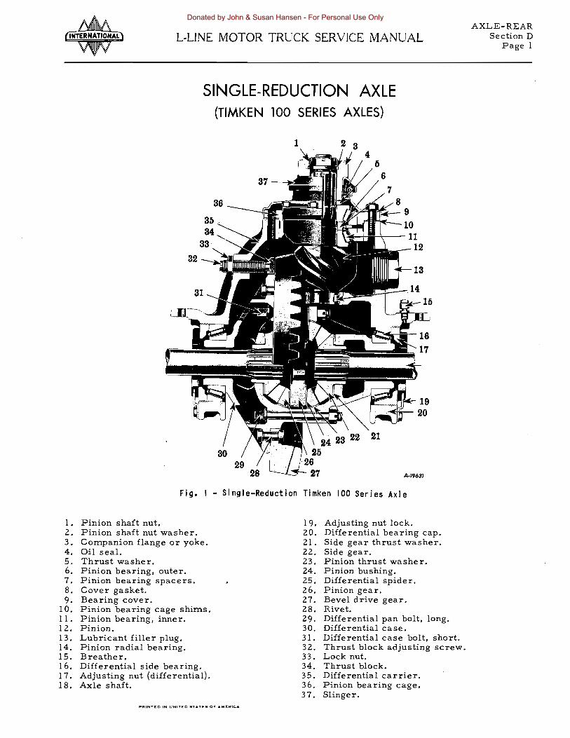
AXLE-REAR Section DL-UNE MOTOR TRUCK SERVICE MANUAL
Page 1
SINGLE-REDUCTION AXLE (TIMKEN 100 SERIES AXLES)
Fig I - Single-Reduction Timken 100 Series Axle
1 Pinion shaft nut 19 Adjusting nut lock 2 Pinion shaft nut washer 20 Differential bearing cap 3 Companion flange or yoke 21 Side gear thrust washer 4 Oil seal 22 Side gear 5 Thrust washer 23 Pinion thrust washer 6 Pinion bearing outer 24 Pinion bushing 7 Pinion bearing spacers 25 Differential spider 8 Cover gasket 26 Pinion gear 9 Bearing cover 27 Bevel drive gear
10 Pinion bearing cage shims 28 Rivet 11 Pinion bearing inner 29 Differential pan bolt long 12 Pinion 30 Differential case 13 Lubricant filler plug 31 Differential case bolt short 14 Pinion radial bearing 32 Thrust block adjusting screw 15 Breather 33 Lock nut 16 Differential side bearing 34 Thrust block 17 Adjusting nut (differential) 35 Differential carrier 18 Axle shaft 36 Pinion bearing cage
37 Slinger PAINTEO IN UNITEO STATES OF AMEFfle
Donated by John amp Susan Hansen - For Personal Use Only
AXLE-REAR Section D L-LINE MOTOR TRUCK SERVICE MANUAL Page 2
TIMKEN SINGLE-REDUCTION AXLES
Description
The Timken Single-Reduction Rear Axle (R-IOO) is a full-floating hypoid-type final drive assembled in a one-piece axle housing
The differential used in the R-lOO Timken Single-Reduction Axle is of four-pinion-type with thrust washers used between the pinions and case The pinions contain bushings which can be renewed when necessary Thrust washshyers are also used between the side gears and case The two halves of the differential case are machined as a complete assembly and must be replaced as such
Removal of Differential Carrier - Hypoid
To remove the differential carrier assemshybly remove plug from bottom of axle housing and drain out the lubricant Disconnect the propeller shaft atfront end of pinion shaft Be sure to replace the universal joint trunnions on their respective journals and hold them in place with a short loop of wire until ready to reassemble Remove axle shafts and differshyential carrier to housing capscrews or stud nuts on heavy-duty axles and take out carrier
When removing the differential from the axle housing it will be necessary to utilize the two puller screws to loosen the differential carrier as shown in Fig 2
The differential thrust block screw shown in Figs 3 amp 4 must be removed before the difshyferential can be removed from the carrier
Differential
The differential assembly of this axle conshysists of four nine-tooth pinions mounted on a spider and two 16 tooth side gears all assemshybled into the differential case -- One half being flanged to mount the hypoid ring gea r
Hardened steel thrust washers are installed between the side and the case and between the pinions and case The differential case is held together by twelve bolts eight of which are longe r than the remaining four
Differential Disassembly
Mark each half of the differential case before teardown so tnat they can be reassemshybled in the original position Wash and inspect all parts and replace any which are at all questionable Oil all parts with gear oil before reassembly Use new lockwashers when reshyassembling
Fig 2 - Loosen lock nuts on two puller screws provided and turn pul Jer screws down into carshyrier It may bemiddot necessary to break carrier loose from housing by striking the carrier with a heavy soft hammer (lead or leather)
Fig 3 - Place differential carrier in suitable holding fixture or overhaul stand and loosen the lock nut on the drive gear thrust block adshyjusting screw Remove thrust block adjusting screw from carrier This wil I permit the thrust block to fall into the carrier
Rotate gear to Ibring holein block iIi line with adjusting
Fig ~ - When replacing thrust block place block on gear and rotate gear to bring block in line with adjusting screw
Donated by John amp Susan Hansen - For Personal Use Only
AXLE-REAR Section DL-UNE MOTOR TRUCK SERVICE MANUAL
Fig 5 - If it is necessary to remove the ring gear from the differential case half carefully center punch each rivet in the center of the rivet-formed head as shown Dril~ through the center of each rivet-formed head using a dril I sl ightly larger than the body of the rivet Punch or press rivet out of gear and case half
If inspection reveals that the ring gear should be replaced exercise care when removshying the ring gear rivets Fig 5 shows the correct way to remove the ring gear rivets to avoid damage to the differential case
The four differential spider pmlOn gears run on bronze bushings and where they are found to be worn excessively the bushings can be replaced Cut the old bushings out of the pinions and using the special tool shown in Fig 6 install and burnish the new bushings in the pinions
Bronze bushings are burnished by means of a stud ball which when being pressed through the pinion bushings compresses the bushing metal giving a denser surface and tighter fit in the pinion The burnishing operation also locks the bushings in place in the pinion since some of the bushing metal is compressed into the locking groove located on the inside bore of the pinion The correct size ball should be ap proximately 005 11 larger than the spider trunshynion Do not attempt to ream the spider pinion bushings
Pinion
The pmlOn cage can easily be withdrawn from the differential carrier with the use of puller screws provided
PRINTED IN UN1TpoundO STATES OF AMERICA
Page 3
Press
Preas burnishiDg ball thro~b bushiDg
Fig 6 - Use bar to press burnishing ball through bushing The correct size bal I should be approximately 005 larger than the differshyential spider trunnion
Remove the pinion shaft from the pinion cage on a press Remove the inner pmlOn bearing with a suitable puller The inner radial bearing retainer is removed after removal of the retainer screw
Pinion Bearing Pre-Load
When the pinion shaft bearings bearing spacers and pinion cage have been reassembled
Fig 7 - Checking pinion bearing pre-load using torque method
Donated by John amp Susan Hansen - For Personal Use Only
AXLE-REAR Section D L-UNE MOTOR TRUCK SERVICE MANUAL Page 4
be sure to check the bearing pre-load Attach a scale to the end of a soft wire wrapped around the pinion cage as in Fig 7 Read the scale only when pinion cage is moving (rotating torque) If first adjustment does not result in correct pre-load select a thicker combinashytion of spacers to decrease or use thinner combinations of spacers to increase the bearing pre-load The rear axle specifications list the correct bearing pre-load for these axles
Gear Adjustment for Correct Tooth Contact
Checking tooth contact is accomplished by means of oiled red lead applied lightly to the bevel gear teeth When the pinion is rotated the red lead is squeezed away by the contact of the teeth leaving bare areas the exact size shape and location of the contacts
Gear Adjustment for Lash
Generally if original gears are being reshyinstalled red leading of teeth will not indicate the same contact as new gears and can be misshyleading Gears that have been in service for long periods form running contacts due to wear of teeth therefore the original shimpack should be maintained to check gear lash Gear lash when using original gears can be reduced only to a point of smooth rotation of gears
If the gear lash in in excess of maximum tolerance as stated under gear adjustment the lash may be reduced only in the amount that will avoid overlap of the worn tooth section Rotate the gears and check for smooth or rough operation If a slight overlap takes place at the worn tooth section rotation will be rough
When installing new gears check gear lash with dial indicator (Fig 8) and adjust to obtain 00611 to 01211 lash as follows
1 To move pinion toward gear remove shims from pack under pinion cage
2 To move pinion away from gear add shims under pinion cage
3 Tomove geartightenor loosendiHerential bearing adjusting nuts as required
After correct gear lash is secured check and adjust as necessary to obtain the correct tooth contact (See gear Adjustmentfor correct tooth contact)
Adjust Differential Bearing Pre-Load
Using dial indicator at back face of ring gear (Fig 9) adjust to obtain bearing pre-load as follows
1 Loosen adjusting nut on side opposite gear teeth only enough to notice end play on inshydicator
2 Tighten same adjusting nut only enough to obtain 00011 end play reading on indicator
NOTE While gear is held in 000 end play and before loading bearings check gear for runout If runout exceeds 008 11 remove differential and check for cause
Fig 9 - Adjusting differential bearing preshyFig 8 - Checking gear lash load
Donated by John amp Susan Hansen - For Personal Use Only
AXLE-REAR Section DL-UNE MOTOR TRUCK SERVICE MANUAL
Page 5
3 Tighten BOTH adjusting nuts one notch each from 000 and play to pre-loaddifferential bearings
4 Tighten bearing cap stud nuts to specified torque (L-lOOand R-100 Axle) (RearAxle Specifications)
5 Install adjusting nut locks capscrews and lock wires
Thrust Block Installation
Turn carrier assembly to bring back face of ring gear facing upward and install the thrust block as follows
1 Place thrust block on rear face of gear and rotate gear until hole in thrust block is aligned with the adjusting screw hole NOTE A light coating of grease placed On the thrust block face will serve to hold the block in position on the rear face of the gear
Fig 10 - Adjusting clearance of thrust block Turn adjusting screw out of carrier Iq turn to obtain 010 to 015 inch clearance
2 Install adjusting screw and lock nut Tightshyen adjusting screw to force thrust block against gear then back off one quarter (14) turn and lock securely with lock nut (Fig 10) Clearance between back face of gear and thrust block is 010 to 015 CAUshyTION Be sure that the adjusting screw end is seated properly in the thrust block hole
Lubrication
1 Remove inspection and oil filler plug (Fig l) and fill to level of plug hole with specshyified lubricant Capacity for the R-lOO axle is 30 pints (30lbs) Capacity of the L-lOO axle is 23 pints (23 lbs)
2 Jack up BOTH rear wheels and operate vehicle in high transmission gear at apshyproximately 25 miles per hour for five minutes to assure proper lubrication of all parts before the Unit is put into service
Both wheels should rotate at approximately the same speed while the vehicle is jacked up Do not allow one wheel to race faster than the opposite wheel To do so might cause serious damage to the differential spider and gears
Use SCL EP gear oil or a multi-purpose gear lubricant suitable for hypoid axles and supplied by a reputable refinery SAE-90 for cold climate and SAE-140 for warm climate
PRINTED IN UNITED STATES OF AMERICA
Donated by John amp Susan Hansen - For Personal Use Only
Donated by John amp Susan Hansen - For Personal Use Only
AXLE-REAR Section EL-UNE MOTOR TRUCK SERVICE MANUAL
Page 1
DOUBLE-REDUCTION TWO- SPEED AXLE (TIMKEN 300 SERIES AXLES)
FAST SPEED HELICAL GEAR
FAST SPEED FREE ROLLiNGVHEN COLLAR
ENGAGES SLOW SPEED PINION
SPACER-SELECTION OF PROPER SPACER GIVES
DESIRED PINION BEARING PRELOAD
SHIFT COLLAR SLIDES ON SPLINED PORTION OF SHAFT ENGAGING DESIRED PINION
SLOW SPEED HELICAL GEAR
SLOW SPEED PINION
CROSS SHAFT ASSEMBLY
AmiddotI579C
Fig I - Two-speed Double-Reduction Drive Unit
Description
The Timken Two-Speed Double-Reduction Final Drive Differential (Fig 7) provides two gear ratios--actually two full size final drives in one unit a fast ratio for maximum speed and a slow ratio for maximum pulling power This feature enables the truck driver to use the proper axle gear combination required for speed load and road conditions
Operation
The first reduction in the Timken TwoshySpeed Double Reduction Drive Axle is through a heavy duty hypoid bevel pinion and gear The hypoid bevel pinion and gear set operates in conjunction with either of two sets of wide-face helical spur gears and pinions of different ratios This second reduction is selective between a fast or slow ratio
The bevel pinion is mounted on two tapered roller bearings in a pinion cage The bevel gear is locked on the cross shaft by a key The cross shaft is mounted on tapered roller bearshyings and carrier two free-rolling helical spur pinions Both spur pinions engage helical spur
PRINTED IN UNITED StATES OF MERICA
gears attached to the tapered roller bearing mounted diffe rential
On the inner side of each of the spur pinions are integral splines On the cross shaft are two rows of splined teeth A shift fork actuated by an electric power shift unit ITIoves the shift collar on the splined portion of the cross shaft to engage the splines on the fast or slow speed spur pinion See Fig 4
When the fast axle speed is selected and torque released the shift collar is moved toshyward the fast speed spur pinion and atthe same time disengages the splines on the slow speed spur pinion The fast speed spur pinion then revolves as part of the cross shaft to drive the fast speed spur gear During this operation the slow speed spur pinion is disengaged so as to rotate freely on the cross shaft Power is transmitted through the hypoid pinion and gear cross shaft clutch collar fast speed spur pinshyion and gear differential and axle shafts
When the slow speed is selected and torque released the shift collar moves in the opposite direction disengaging the fast speed spur pinshyion and locking the slow speed spur pinion as part of the cross shaft Power is then transshymitted through the slow speed spur pinion and gear differential and axle shafts
Donated by John amp Susan Hansen - For Personal Use Only
AXLE-REAR Section E L-LINE MOTOR TRUCK SERVICE MANUAL Page 2
The design of the shift collar prevents disshyengagement until the opposite gear ratio is selected and torque released
Adjustments and Clearances
Various clearance adjustments are proshyvided for both in the axle gearing and shifting mechanism These adjustments once made seldom need attention Where a disassembly job is to be performed the detailed information found in Shop Talk No 34 will be most helpful
Hypoid Pinion and Cage
The pinion and bearings are installed in the pinion cage witha pre-load secured by following the instructions under PinionBearing Pre-Load Sec A The pre-load in controlled by proper selection of spacers or combination of spacers located between the outer pinion bearing and bearing seat on the pinion shaft (Fig 1) These spacers are ground to close tolerances and are available in graduated thicknesses Thicker spacers decrease bearing pre-load and thinner spacer bearing pre-load For correct procedure see pinion bearing adjustment for correct pre-load Sec A
When installing the pinion cage assembly in the differential carrier be sure that the oil passage holes in the carrier housing gasket shim pack and pinion bearing cage are aligned When the original gears are being reinstalled use the original shim pack plus a new gasket under the pinion cage
Hypoid Ring Gear and Cross Shaft
The hypoid ring gear is assembled on the cross shaft by pressing the gear firmly against the cross shaft shoulder (Fig 2) To facilitate
~~~IJjjfii~ 010 MINf
C[EARANC~ 7WHEN~
HypoilYGEAR IS PRESSEDfshy A-GAINSf -fiKSEAT
Fig 2 - Pressing hypoid gear on cross shaft
installation the gear may be heated to 200 to 2500 F Be sure the key is in line with the key slot in the gear before pressing the gear into place
The fast speed pinion located between the hypoid ring gear and splined teeth on the cross shaft should have an end play of at least 010 11
bull
Normal end play will be from 015 minimum to 030 11 maximum The slow speed pinion end play must also check to a minimum of 010 The shift collar is installed over the springs and poppets with the longer splines on the inshyside diameter of the collar toward the hypoid ring gear
The cross shaftbearing pre-load is measshyured by wrapping wire around the slow speed pinion and pulling with a scale to a reading of approximately 8 pounds rotating torque (not starting torque) (Fig 3)
To obtain correct pre-load add or remove shims at shim pack under bearing cage on cross shaft end opposite ring gear Use origishynal shim packs plus a new gasket when reinshystalling original gears
Fig 3 - Checking cross shaft pre-load bull
Gear Tooth Impression and Lash
When the hypoid gear sethas been renewed adjust gear back lash with dial indicator and adjust to obtain 006 to 01211 lash Movement of the gears is controlled as follows
1 To move pinion toward ring gear remove shims from pack unde r pinion cage
2 To move pinion away from ring gear add shims to pack under pinion cage
3 To move ring gear away from pinion reshymove shims from pack under cross shaft bearing cage (side opposite ring gear) and add shims of equal thickness to pack under
Donated by John amp Susan Hansen - For Personal Use Only
AXLE-REAR Section EL-UNE MOTOR TRUCK SERVICE MANUAL
Page 3
cross shaft bearing cage (ring gear side) Shims should be transposed in this manner to maintain the established pre-load
4 To move ring gear toward pinion remove shims from pack under cross shaft bearing cage (ring gear side) and add shims of equal thickness to pack under cross shaft bearshying cage (side opposite ring gear) Shims should be transposed in this manner to maintain the established bearing pre-load
When correct gear lash is obtained check and adjust as necessary to obtain correct tooth contact using oiled red lead applied lightly to the ring gear teeth Gear tooth impression illustrations are shown in Section A pages 3 and 4
Shift Collar Adjustment
The shifting collar serves as the lock beshytween the cross shaft and either the high or the low speed spur pinions When engaged with either speed spur pinion the collar must be flush against the spur pinion face (Fig 4) The collar is held flush against the pinions by three spring loaded poppets located in the cross shaft and unless there is misadjustment in the locashytion or travel of the shifting fork the collar will seat itself against whichever gear is selected
Fig ~ -Checking clearance between shift collar and spur pinion Clearance shoul~ not be less than 010
To check the travel of the collar when the differential is mounted on the axle housing it is necessary to remove the pinion cage assembly Illustrations show details of the checking proshycedure with the carrier removed from the axle housing and the differential gear assembly reshymoved
Check clearance of shift fork collar (flat) faces in shift collar with feeler gauge (Fig 4) The clearance should not be less than 010 minimum on each side of the fork in both the fast and slow speed positions When checking this clearance the shift collar must be flush with the end face of the spur pinion in both fast and slow positions
Shims located at the shifting chamber bracket regulate the travel range of the shift rail and fork Add or remove shims to allow the shift collar to seat flush against the spur pinions in both high and lowpositions (Fig 5 amp 6) The electric shift chamber and bracket assemshybly must be removed from the carrier in order to remove shims
Spring - completes shift when engine torque
is released
I
A-22924
Fig 5 - Details of front mounted electric shifting mechanism Note location of shims for travel adjustment
Electric shift motor
Spring-completes shift when engine torque
is released
Fig 6 - Showing details of side mounted electshyric shift mechanism Shims are provided to adshyjust travel of shift fork Overhaul procedure for the electric shifting unit is given in the Electric Shift Section HR
PRINTED IN UNITED STATES OF AMERICA
Donated by John amp Susan Hansen - For Personal Use Only
AXLE-REAR Section E L-UNE MOTOR TRUCK SERVICE MANUAL Page 4
Fig 7 - Adjusting stop screws to limit travel of shifting fork Fig ~ shows point of contact of the screws with the shifting collar
Adjusting screws located on top of the carshyrier housing (Fig 7) provide means of limiting the travel of the shifting fork and rail Turn in or out on each adjusting screw to stop the travel of the shifting fork so that the fork does not bear against the sides of the shifting collar after the collar is seated flush with the spur pinionface in both high and low positions There must be a minimum of 01 on clearance between the fork and shift collar This clearance is to assure that the collar is free of shifting fork interference and allows the poppets to hold the collar against either qf the spur pinions Also the 01 on minimum clearance is running clearshyance between the forks and collar sides to preshyvent unnecessary wear to the two parts
Differential Adjustment
The differential assembly is installed in the carrier with the helical gears located to provide approximately 11611 clearance between the helical gear sides and shift collar faces in both the fast and slow speed positions Move the differential assembly from side to side to obtain this adjustment by turning on the adjustshying nuts
Using dial indicator at the side face of one of the helical gears adjust to no end play (OOO end play) in the differential bearings Rotate assembly several times to assure normal bearshying contact Tighten adjusting nuts one notch each from 000 end play to secure the correct differential bearing pre-load
With the dial indicator contacting the side face of the helical gear check for runout If runout exceeds 008 remove differential and check for middotcause
Lubrication
1 Before starting new truck and after overshyhaul remove pipe plug at pinion cage and insert one pint of specified lubricant
2 Fill axle housing to correct level with specshyified lubricant Capacity is 18-12 quarts (37 1bs)
3 Jack up BOTH rear wheels and operate vehicle in high transmission gear at apshyproximately 25 miles per hour for five minutes to assure proper lubrication of all parts before the unit is put into service
Both wheels should rotate at approximately the same speed while the vehicle is jacked up Do not allow one wheel to race faster than the opposite wheel To do so might cause serious damage to the differential spider and gears
Use SCL EP gear oil or a multi-purpose gear lubricant suitable for hypoid axles and supplied by a reputable refinery SAE-90 for cold climate and SAE-l40 for warm climate
When reassembling the differential gears thrust washers cross shaft spur gears and bearings lubricate the wearing surfaces with a light coat of specified axle lubricant This will help provide initial lurication
Fig 8 - Insert one pint of lubricant in pinion cage before starting new truck or after overshyhau I
Electric Shift
The electric shift mechanism used on all Tirnken double-reduction two speed axles is identical with the electric shift used on Eaton two speed axles For detailed information see Electric Shift Section H
Donated by John amp Susan Hansen - For Personal Use Only
AXLE-REAR Section FL-UNE MOTOR TRUCK SERVICE MANUAL
Page 1
DOUBLE-REDUCTION AXLE (TlMKEN 200 SERIES AXLES)
(See Shop Talk No 25 for complete illustrated disassembly)
Hypoid gear
Hypoid pinion
Differential case
Helical gear A-I0067
Fig I - Double-Reduction Drive Unit (Timken)
The Timken S-200-P and U-200-P series double-reduction rear axles (Fig 1) introduce improvemen ts in des ign and cons truction over conventional rear axles for on-highway and offshyhighway service in heavy-duty motor trucks
These axles provide increased torque cashypacity and eliminate the former need because of specific chassis requirements for both topshymounted and front-mounted double-reduction final drive units The differential carrier on the S-200-P and U-200-P axles is mounted at an elevation which is a satisfactory comproshymise between the two extremes
The S-200-P and U-200-P rear axles emshyploy the same differential and carrier assemshyblies They differ only in that the rear axle housing of the S-200-P is of lighter construcshytion for the S-200-P axle is not intended for off-highway service
Drive Unit
The drive unit or differential carrier asshysembly is mounted on the sloping front face of the axle housing and is readily removable for periodic inspec tion The differential bearing
legs are dowelled in the axle housing to elimshyinate deflection under torque load
Pinion Shaft Location
The pinion shaft is located at an elevation midway between that used on the front-mounted type axles where the pinion shaft is on the axle center line and that used on the topshymounted type axles where the pinion shaft is considerably above the axle center line (Fig 1)
Final Drive
The final gear-drive consists of a large diameter hypoid bevel gear and bevel pinion for the first reduction and a wide-faced helical gear and helical pinion for the second reduction
A range of gear ratios is available to meet all operating requirements (See Specifi shycations)
Axle Housing
The axle housings in both axles are simishylar in design although the U-200-P axle housshying has larger sections to produce its greater load carrying capacity
PRINTED IN UNITED STATES OF MERICA
Donated by John amp Susan Hansen - For Personal Use Only
AXLE-REAR Section F L-UNE MOTOR TRUCK SERVICE MANUALPage 2
Differential
The differential assembly of this axle conshysists of four 9-tooth pinions mounted on a spishyder and two 16-tooth side gears all assembled into the differential case both halves of which are identical
Hardened-steel thrust washers are inshystalled between the side gears and the case and between the pinions and the case The large helical gear is mounted between the differential case halves and the assembly is held together by twelve rivets The differential assembly is mounted in tapered roller bearings
on Seals 419634
Fig 3 - Illustrates wiper ring and gasketThe rear wheel outer oil seal is illusshy
trated in Fig 2 This is the latest type oil seal assembly and when installing this seal be sure to cement the new cork gasket to the inner flange of the new wiper ring
Fig 11
Axle shaft
Cork gasket cemented to seal wiper AI60f4
Fig 2 - Illustrates installed
sectional view of seal
The seal wiper and cork gasket are pressed over the end of the axle tube Be careshyful not to bend or damage the seal wiper when installing (Fig 3)
The seal retainer assembly is placed over the axle flange studs as shown in Fig 4 using a gasket on both sides of the seal retainer asshysembly
The rear wheel inner seal construction is illustrated in Fig 5 Before installing the inner seal check the location of the bearing and oil seal spacer to be certain that the seal lip on the oil seal assembly faces toward the oil seal wiper ring in the wheel hub as shown
Special adapters should be used in seal installation as described in Service Bulletin B-97-1946 and Addendum No 1 Fig 5 - Rear wheel inner seal
Donated by John amp Susan Hansen - For Personal Use Only
AXLE-REAR Section FL-LINE MOTOR TRUCK SERVICE MANUAL
Page 3
To remove the cross shaft it is necessary to fir st remove the differential and helical ring
Lubrication
1 Before starting new truck and after overshyhaul remove pipe plug at pinion cage and insert one pint of specified lubricant
2 Fill axle housing to correct level with specified lubricant The various axle cashypacities are found in Lubrication Section
3 Jack up BOTH rear wheel and operate veshyhicle in high transmission gear at approxishymately 25 miles per hour for five minutes to assure proper lubrication of all parts before the unit is put into service
Both wheels shOUld rotate at approximately the same speed while the vehicle is jacked up Do not allow one wheel to race faster than the opposite wheel To do so might cause serious damage to the differential spider and gears
Use SeL EP gear oil or a multi-purpose gear lubricant suitable for hypoid axles and supplied by a reputable refinery SAE-90 for cold climate and SAE-l40 for warm climate
Hypoid Pinion and Cage
The pinion and bearings are installed in the pinion cage with a pre-load as indicated in Rear Axle Specifications for these axles The pre-load is controlled by proper selection of spacers or combination of spacers located between the outer pinion bearing and bearing seat on the pinion shaft These spacers are ground to close tolerances and are available in graduated thicknesses Thicker spacers deshycrease bearing pre-load and thinner spacers increase bearing pre-load For correct proshycedure see Pinion Bearing Adjustment for correct pre-load Section A page 6
When installing the pinion cage assembly in the differential carrier be sure that the oil passage holes in the carrier housing gasket shim pack and pinion bearing cage are aligned When the original gears are being reinstalled use the original shim pack plus a new gasket under the pinion cage
Helical Gear Shaft (Cross Shaft)
The helical gear or cross shaft is mounted at right angle s to the hypoid pinion shaft in the carrier housing This shaft is a one -piece steel forging consisting of an integral helical drive pinion gear in the center The hypoid ring gear is aligned with key in shaft before pressing gear onto shaft
PRINTEO IN UNITED STATES OF AMERICA
gear assembly second withdraw the hypoid ring gear when being removed (Do not remove universal joint flange) Then remove both bearing cages move shaft enough to allow bearing at ring gear end of shaft to clear the carrier housing and tilt shaft to rear for reshymoval from carrier
The correct bearing pre-load is obtained by adding or removing shims at shim pack under the cross shaft bearing cage at end opshyposite hypoid ring gear Use orignial shim pack plus a new gasket when reinstalling ori shyginal gears To measure correct bearing preshyload follow method outlined for Timken DoubleshyReduction Two-Speed Axles Section E Fig 3
Donated by John amp Susan Hansen - For Personal Use Only
Donated by John amp Susan Hansen - For Personal Use Only
AXLE-REAR Section GL-L1NE MOTOR TRUCK SERVICE MANUAL
Page 1
TANDEM AXLES
See Legend on following page 8-4745
Fig I - Details of axle mounted power divider mounted on forward rear axle
AXLES--RF-1475 RF-1575 RF-1685 FOUR-WHEEL AXLE-MOUNTED POWER
DIVIDER
The above axles have a power divider built as an integral part of the differential assembly This results in a more simplified tandem axle design with less moving parts The compactshyness of the combined power divider and differshyential makes possible the use of fewer propeller shafts and eliminates the need for a propeller shaft hanger at the rear of the vehicle The
power from the engine is delivered through the transmission (and auxiliary transmission where the truck is so equipped) to the power divider which as the name implies divides the power between the two axles A differential unit is included in the power divider to comshypensate for the difference in speeds between the two axles This difference in axle speeds is brought about by wheels Slipping on either of the axles or slightly different tire diameter due to tire wear (Both rear axles on sixshywheel (6x4) trucks have the same axle differshyential ratio)
PRINTEO IN UNITEO JTTpoundS OF AMERiCA
Donated by John amp Susan Hansen - For Personal Use Only
AXLE-REAR Section G L-LINE MOTOR TRUCK SERVICE MANUAL Page 2
Legend For Fig 1
1 Mainshait 2 Companion flange retaining nut
3 Companion flange 4 Thrust washer
5 Slinger 6 Felt 7 Oil seal B Bearing cover retaining nut 9 Bearing cover
10 Bearing cover gasket 11 Mainshait bearing front 12 Differential lock 13 Transfer case cover 14 Thrust washer 15 Forward axle bevel pinion shaft 16 Pinion bearing cage cover 17 Outer pinion bearing nut lB Pinion bearing cage capscrew 19 Pinion bearing cage cover seal 20 Pinion bearing cage 21 Shims 22 Thrust washer 23 Pinion bearing outer 24 Pinion bearing spacer 25 Pinion bearing inner 26 Spacer 27 Differential spider thrust washers power
divider 2B Transfer case 29 Forward axle helical drive gear 30 Oil seal assembly 31 Pinion bearing 32 Pinion bearing sleeve 33 Pinion bearing sleeve set screw 34 Power divider to differential carrier
mounting capscrew 35 Power divider to differential carrier
mounting gasket 36 Differential carrier 37 Bevel ring gear 38 Differential lubricator 39 Differential lubricator retaining capscrew 40 Differential carrier bearing adjuster 41 Differential carrier mounting capscrew
Rear-rear axle drive shaft outer bearing cover assembly flange nut and thrust washer are identical with the units on outer end of mainshaft
A differential lock is available for the power divider This locking arrangement is used to lock both the front rear and rear rear axles together and is generally us ed when the vehicle is operating in mud snow or off the highway
42 Differential carrier to axle housing mountshying gasket
43 Axle shaft 44 Differential carrier bearing 45 Adjuster lock 46 Differential case bolt and nut 47 Bevel ring gear rivet 48 Differential case flange half 49 Differential spide r 50 Differential spider pinion gear thrust
washer 51 Differential spider pinion gear 52 Differential case plain half 53 Differential side gear thrust washer 54 Differential side gear 55 Axle torque arm 56 Axle housing 57 Rear-rear axle drive shaft companion
flange 58 Rear helical and side gear thrust washer 59 Rear helical and side gear 60 Breather 61 Differential case (male) 62 Differential spider 63 Differential case (female) 64 Rear-rear axle helical drive gear 65 Differential case bolts 66 Differential spider pinion gear 67 Front helical and side gear 6B Rear-rear axle helical drive gear 69 Transfer case cover mounting gasket 70 Transfer case cover 71 Transfer case cover mounting capscrews 72 Thrust washer 73 Drive shaft bearing inner 74 Drive shaft nut inner end 75 Rear-rear axle drive shaft 76 Shifter fork 77 Shift fork bracket mounting gasket 7B Shift fork bracket retaining capsc rew 79 Shift fork lever 80 Shift fork lever boot 81 Shift fork bracket
NOTE Rear-rear axle drive shaft inner bearing (73) and nut (74) are identical with mainshaft inne r bearing and nut
CAUTION The differential must not be held in the locked position longer than necesshysary Driving the vehicle on improved or paved roads with the differential lock engaged will subject the axles and gears to unnecessary strain The differential lock shift fork is spring loaded and automatically releases the lock when shift lever is released by operator
Donated by John amp Susan Hansen - For Personal Use Only
AXLE-REAR Section GL-LINE MOTOR TRUCK SERVICE MANUAL
Page 3
DISASSEMBLY OF POWER DIVIDER (AXLE MOUNTED)
To disasseInble the power divider proceed as outlined in the following steps
1 ReInove nine power divider to differential carrier Inounting capscrews and lift off the power divider Be sure Inounting gasket is also reInoved
2 Place power divider in a transInission stand or other suitable fixture and reInove the four pinion bearing cage Inounting capshyscrews and reInove pinion shaft cover
3 ReInove self-locking setscrew in the transshyfer case to release pinion bearing sleeve
4 ReInove pinion shaft outer bearing nut and using a soft haInIner tap end of shaft to release pinion bearing sleeve and bearing froIn housing Withdraw pinion shaft asshyseInbly froIn transfer case COInplete disshyasseInbly of shaft by reInoving inner pinion bearing spacer front axle helical drjve gear and pinion bearing
5 ReInove pinion bearing cage froIn transfer case
6 ReInove Inainshaft bearing retainer nut inner end
7 ReInove cOInpanion flange mounting nut and using a suitable puller reInove COInshypanion flange and slinger asseInbly
S ReInove four bearing cover capscrews and lift off bearing cover
9 Using a bronze bar drive inner end of Inainshyshaft until shaft passes through rear helical and side gear and thrust washer This gear and washer can now be reInoved through pinion bearing sleeve opening in transfer case
10 Continue pushing mainshaft toward front of transfer case until differential case asshyseInbly and thrust washers are free of shaft Differential case will also pass through pinion bearing sleeve opening in case Mark differential case halves so original asseInbly can be duplicated Keep differential spider thrust washers with differential case to asshysure correct reasseInbly
11 Withdraw Inainshaft all the way Front helical and side gear thrust washer and differential lock (where power diviltler is so equipped) can now be reInoved through pinion bearing sleeve opening
12 Using a suitable puller reInove both front and rear Inainshaft bearings This COInshypletes disasseInbly of Inainshaft
13 ReInove the nine transfer case cover reshytainer screws Carefully reInove cover so as not to daInage cover or gasket face of transfer case as cover Inust be reInoved froIn front bearing of rear rear axle drive shaft
14 ReInove nut at front end of rear rear axle drive shaft The cOInpanionflange at rear of shaft should be used to hold shaft while reInoving nut
15 ReInove COInpanion flange retaining nut and flange at rear of rear rear axle drive shaft ReInove cOInpanion flange with suit shyable puller
16 ReInove the four bearing cover retaining capscrews and reInove bearing cover
17 ReInove bearing at front end of rear rear axle drive shaft using a suitable puller Also reInove helical gear retaining washers
18 Tap front end of rear rear axle drive shaft with a soft haInIner to reInove helical drive gear and spacer This action will also drive the rear bearing out of case so that the shaft Inay now be lifted out
19 Place rear rear axle drive shaft in vice having soft jaws and pull the rear bearing off the shaft
The power divider is now cOInpletely dis asshyseInbled Place all parts in a cleaning solution to reInove all dirt and sludge deposits Be sure transfer case is free of any loose Inetal particles Carefully inspect all parts and replace any that are doubtful as to further satisfactory serviceshyability
To reasseInble the power divider the exact reshyverse procedure as outlined for disasseInbly should be used However it is advisable to observe the following precautions
Be sure all sealing surfaces are free of nicks and that the old gasket Inaterial has been COInshypletely reInoved NOTE The transfer case to differential carrier Inounting gasket is ODS thick
The differential case was Inarked as to forshyward side and also for correct reasseInbly of the two case halves It is of utInost iInportance that the eight differential case Inounting bolts be so installed that the bolt heads are also on forward side of differential asseInbly after installation in power divider NOTE FeInale half of differential case should be forward
PRINTED IN UNiTEO STATES OF ERICA
Donated by John amp Susan Hansen - For Personal Use Only
AXLE-REAR Section G L-LfNE MOTOR TRUCK SERVICE MANUAL Page 4
To secure the pinion bearing pre-load reading specified in the Rear Axle Specifications for this model axle see Pinion Bearing Adjustment for Correct pre-load Make a bench assembly of bevel pinion shaft bearings spacers and pinion bearing cage Place all parts in the same position as in the final assembly The pinion shaft assembly may now be placed in the press shown in Fig 2 After the correct pinion bearshying pre-load reading has been secured remove outer pinion bearing and pinion bearing cage only The pinion shaft is now ready for install shyation Complete assembly of pinion shaft to transfer case by inserting pinion shaft through pinion bearing sleeve opening until sleeve is in correct position Install pinion bearing cage outer pinion bearing thrust washer and nut Do not fail to install pinion bearing sleeve set screw after the cone center and back lash adshyjustments have been made Use a new bearing cage cover oil seal when completing assembly
After the correct pinion bearing pre-load has been obtained mount power divider on differshyential carrier The pinion cone center adjustshyment may now be made Follow procedure set forth under SE-I065 Pinion Setting Gauge Bear in mind the adjustment of the bevel pinion is controlled by means of a shim pack under the pinion bearing cage at forward side of power divider The differential assembly may noW be completed and the bevel ring gear adjusted for back lash -- as marked on outer rim of ring gear Be sure to obtain a tooth contact pattern as outlined under General Rear Axle Hypoid Pinion and Ring Gear Adjustment Point Imshypression Method
The differential carrier and power divider assembly is now complete and ready for inshystallation in forward rear axle housing Use a new differential carrier mounting gasket
Center Cross Bar
The assembly of the center cross bar and saddle is shown in Fig 2 The sleeve is loshycated in the saddle and is locked in place by two thru-bolts Inside the steel sleeve there is a center cross bar which must rotate freely in the sleeve In the LF-l 70 the center cross bar is solid steel and on theLF-190andLF-210 it is a steel tube In removing the tube or cross bar it is first necessary to jack up the rear end of the truck remove the spring shackle pins remove the two equalizer beam end bolts then remove the saddle equalizer beam and the springs The tube or cross bar is then removed from the supporting sleeve
Equalizing Beam Ends
Equalizing beam end construction is shown in Fig 3 The beam end ball is supported in a two-piece bronze socket which is pressed into the beam end Lock bolts prevent the sockets
BUSHING 11-16155
Fig 2
Felt retainer Nut Lockwasber
Felt seal
Lubricato----i~
A-22712
Fig 3
Donated by John amp Susan Hansen - For Personal Use Only
AXLE-REAR Section GLLINE MOTOR TRUCK SERVICE MANUAL
Page 5
from moving and felt seals with spring retainshyers are used to guard against leakage of lubrishycant and entrance of dirt
When replacing a socket or ball assemble both halves of the socket to the ball and press the assembly into the beam end Make sure that the grease hole in the socket indexes with the lubricator hole in the beam end - THIS IS VER Y IMPORTANT Both sides of the socket must be counterbored flush with counterbore in beam so that the socket lock bolt and plain washers will prevent the socket from shifting
Install felt seals and spring retainers before as sembling the beam end to the bracket The beam end bolt nut should be drawn up as tight as possible and securely locked with a cotter pin
Torque Rods
Figure 4 illustrates the torque rod end assembly used on six-wheel L-line models Shims are used between the ball sockets to provide proper adjustment
To disassemble remove the torque rod ball cap then tap the torque rod near the bronze socket and the lower half of the socket will slip out The ball stud nut should then be removed and the ball stud driven out of torque rod
Reassembly is accomplished in the reverse manner Press upper half of ball socket into torque rod and insert ball stud Install shims (approximately 035 11) and insert lower half of socket Assemble cap and tighten securely Check movement of ball stud uSing a piece of tubing about 16 long as a lever If ball stud moves too freely remove a 005 shim and if too tightly add another 005 shim Only a slight drag should be felt
NOTE Be sure that the felt seal retainer and spring are replaced to prevent leakage of grease and entrance of dirt
ltW~b---Cotter pin
Nut
Torque rod ball
Amiddot22729
Fig ~
PRINTED IN UNITED SfATES OF AMERICA
Donated by John amp Susan Hansen - For Personal Use Only
Donated by John amp Susan Hansen - For Personal Use Only
AXLE-REAR L-LINE MOTOR TRUCK SERVICE MANUAL Section H
Page 1
ELECTRIC SHIFT (EATON) USED ON EATON AND TIMKEN TWO-SPEED AXLES
Shifting motor
assembly
Fig I - Electric Shift Unit Mounted on two speed axle
Description
The electric shift device consists in the main of an electrically operated shifting fork and shifting unit located on the two-speed axle (Fig 1) The shift fork is activated by a twoshydirectional coil spring and lever assembly (Figs 6 and 7) The purpose of this spring and lever asseInbly is to rrove the shiftfork quickshyly into the high or low speed position when gear load is InoInentarily reInoved froIn the differential
The actual shifting or gear moveInent is perforIned by the coil spring located in the housing of the electric shift unit The coil spring which perforIns the shift Inust be placed under tension or in a loaded state before gear shift can be accomplished This is provided for by a reversible electric Inotor which drives a power screw which in turn actuates a drive nut in either direction Trunnions on either side of the drive nut engage slots in the spring lever l1oveInent of the lever in either direcshytion energizes the spring which perforIns the shifting InoveInent
The control of the electric shift unit is by means oia two-way switch located on the transshyInission gear shift lever (Figs 2 3 and 4) Moving control button up or down causes Inotor at axle shift unit to rotate in either direction A UInit switch located in the electric shift unit
Switch receptacle
(part of wire I harness)
Fig 2 - Electric Shift Unit Two Way Control Switch
(Figs 3 and 6) opens the circuit and stops the Inotor when the shifting spring is fully enershygized Any time thereafter the shift is COInshypleted by the energy of the spring when torque is InoInentarily released froIn the differential gears either by releasing the clutch or closing the throttle
A two-speed adapter electrically operated is located at the speedoIneter and is wired in series with the ignition switch (Figs 2 3 and 5) The balance of the electrical circuit is also wired in series with the ignition switch thereby preventing any closed electrical cir shycuits in the systeIn when the truck is idle and the ignition switch is turned to the OFF poshysition
Gear shift
A D To lever switch Shift motor
Circuit hreaker
ignition switch
Automatic - switch
Red B -----(-----J
------- Black C Amiddot22525
Fig 3 - Electric Shift Circuit Diagram PRINTEO IN t)NITED STATes OF AMRICA
A-22894
Donated by John amp Susan Hansen - For Personal Use Only
AXLE-REAR Section H L-UNE MOTOR TRUCK SERVICE MANUAL Page 2
Shifting motorTwo-way assemblyswitch
A-22895
Fig ~ - Illustration Of Electric Shift Parts
The system is further protected by a selfshyresetting circuit breaker which becomes operative when normal current flow continues for a period longer than is required to complete a shift or in case of an overload or direct short
Details of the various units of the Electric Shift their function and the servicing of each fonows
The switch (Fig 2) with which the operator controls the axle is located on the transmission gear shift lever
This control switch has two positions -- up and down Three wires are connected to the switch When the selector button of the switch is up the battery wire (A -- Fig 3) is conshynected to wire (B -- Fig 3) leading to one field of the motor in the axle shift unit proper
When the button is down the battery wire is connected to wire (C -- Fig 3) leading to the other field of the axle shift unit motor and also to the speedometer adapter
As shown in Fig 2 the control switch is connected to the harness or wiring system by plugging into the three-pronged connector which is part of the harness The switch is removable by slipping the rubber boot up to the knob and pulling apart
Wiring System
The wiring system or harness as shown in Fig 3 has four terminals Two of them (b) and (c) in a double line run to the axle shift unit on the axle Of these the longer red one is conshynected to the bottom terminal and the shorter black one is connected to the top terminal The short single black wire (c) is connected to the speedometer adapter and the green wire (a) is connected to the circuit breaker Wire (d) connects the copper stud of the circuit breaker to the cold side of the ignition switch The
Fig 5 - Speedometer Two-Speed Adapter
circuit breaker protects the system in the event of a short circuit Should a short circuit occur it will open the circuit until the trouble has been corrected
Speedometer Adapter
The speedometer adapter (Fig 5) compenshysates for variations in the speed of the drive shaft between high and low-speed range of the axle
This adapter is held in the high range by a spring and in the low range by an electro magshynet The inner mechanism is lubricated and sealed for life but the two shaft ends should occasionally receive a small amount of light oil at the oil-wick cups
Axle Shift Unit
This unit shifts the axle into high or lowshyrange Fig 6 shows the axle shift unit in the high range of the axle In this position wire (b) (Fig 3) carries current to one field of the motor (6) (See Fig 20 for Part Identification) so that the armature and drive screw (20) turn in a clockwis e direction and move the nut down When the nut has traveled a sufficient distance to wind the spring (23) a contact bumper on the nut breaks an electrical connection on the automatic switch (17) so that the motor is no longer energized and the armature stops rotatshying To make sure that the nut cannot travel back on the screw due to vibration a ball screw detent spring (Fig 12) mounted on the cover (26) holds the nut at the end of its travel on the screw The nut moves the spring winding lever (24) down which pivoting on the pin (21) winds the tors ion spring (23) for high Thus an inshycreased load is put on the spring and in this position the axle is ready to snap into the high speed ratio as soon as the load on the axle gears is relieved The torsion spring is assembled in the unit so that it is under 45 to 65 pounds pressure depending on the size of the axle When the spring winding lever is moved so that the spring is wound the pressure
Donated by John amp Susan Hansen - For Personal Use Only
AXLE-REAR Section HL-LINE MOTOR TRUCK SERVICE MANUAL
Page 3
screw
Limit switch
Fig 6 - Axle Shift Unit In High-Range Position
Lever assembly
Power screw
Drive ---- shynut
Limit switch
Amiddot22893
Fig 7 - Axle Shift Unit In low-Range Position
of the spring is raised tofrom 90 to 135 pounds again depending on axle size
This additional means is us ed to shift the axle and when the shift is completed the ends of the spring come together leaving the origishynal tension of 45 to 65 pounds on the spring This preload tension holds the axle in either gear
Shift To Low
When the button is pushed down the motor is energized so that the screw moves counter clockwise and the nut travels to the top windshying the spring for a shift to low in the same manner as before
SERVICE AND TROUBLE SHOOTING
General Information
1pound the electric shift should fail to operate properly the trouble should first be located A very handy tool for this is a test light conshysisting of a light bulb either 6 or 12 volts depending on the electrical system of the truck with two wires a few feet long and small battery clips on the ends Refer now to the wiring diagram Fig 3 and first connect the test light to Point (d) on the circuit breaker under the dash or hood depending on the test light to ground Turn on ignition switch or accessory switch in the case of a diesel and the light should show If it fails to light at this point there is a poor connection or broken wire between the ignition switch and circuit breaker Next connect test light to Point (a) on the circuit breaker -- Fig 3 -- and again the light should show If it fails to show imshymediately watch the light carefully and listen to the circuit breaker for a minute to see if it is flashing off and on The light should stay on continuously at this point If it flashes off and on or you hear the breaker clicking it indicates that too much current is flowing and the circuit breaker is opening This is due either to a short circuit or the motor in the shift unit not being free to run To detershymine which of these it is remove the two wires (b) and (c) from the axle shift unit and recheck If the light still flashes off and on or you still hear the breaker clicking it is due to a short in the harness but if the light now stays on continuously the trouble is in the shaft unit
If there is no light at all at this point and the circuit breaker cannot be heard clicking disconnect the green wire from terminal (a) Fig 3 and again clip the test light to terminal (a) post on the circuit breaker If the light fails to show here and did show on terminal (d) the circuit breaker is bad and should be reshyplaced
If the test light glowed normally at point (a) next remove the two wires (b) and (c) from the axle shift unit and connect a test light wire to one of these wires and the other test light wire to ground The red shift unit wire should light the light only in high gear or up position on the gear shift lever switch andthe black wire should light the light only in the low gear or down position of the gear shift lever switch If the light fails to glow in either of the above tests it indicates a broken circuit in the harshyness or gear shift lever switch If both wires light the test light in one position of the gear shift lever switch it indicates a short circuit in the harness or gear shift lever switch
Next connect the test light to the speedomshyeter adapter terminal (c) and ground Here
FRINTED IN UNITpoundD SrATE$ 0 AMEAICA
Donated by John amp Susan Hansen - For Personal Use Only
AXLE-REAR Section H L-UNE MOTOR TRUCK SERVICE MANUAL Page 4
the light should glow in the low gear or down position of the gear shift lever switch only 1pound it fails to glow it indicates a broken circuit in the harness or gear shift lever switch
These checks above will quickly locate the trouble When checking the harness for short or open circuits watch for broken insulation and do not overlook ~ gear shift ~ switch which can best be tested by substituting a new one in its place
If the vehicle shifts normally but the speedometer adapter fails to operate properly make the above check with the test light to see if it is getting current in the low range and if it is replace the adapter When the trouble has been traced to the shift unit disassemble as shown under disassembly and inspect the parts carefully All parts can be washed in cleaning solvent except the motor
When inspecting the parts most failures will be readily apparent however a few assemblies should be checked as follows
Automatic Switch
The automatic switch (17) Fig 20 (servshyiced only as an assembly) should have clean free moving points which close firmly under spring tension
Drive Screw
The drive screw (20) Fig 20 (serviced only as an assembly) should turn freely by roshytating the s crew while holding the nut When the nut gets to the end of the screw the screw can continue to turn but the nut should not jam or run off the end By turning the screw in the opposite direction the nut will go to the other end and stop as before while the screw can continue to be turned
The fiber bumper in the nut should be a tight press fit Be sure in assembly that this fiber bumper is in towarcfthe switch
Motor
The motor (6) Fig 20 (serviced only as an assembly) is reversible so that with the motor housing connected t6 one battery terminal and either one of the two motor wires connected to the other battery terminal the motor will run in one direction With the other motor wire connected to the battery the motor will run in the opposite direction The motor has a stall torque of approximately 6 lbs The way to check this motor is to put a small crescent wrench on the rectangular drive on the armashyture shaft Hold the wrench in one hand hold the motor itself firmly in the other hand or in a vis e and then connect one motor wire to a battery terminal and connect the motor housing
to the other battery terminal The wrench should then tend to turn with a torque or pull of about 6 lbs Allow the wrench to turn very slowly making sure that this pull or torque is present the full 3600 turn of the wrench If one armature winding of the motor is burned out this torque will disappear for a small part of the 360 0 bull While making this test care should be taken not to overheat the motor This motor is lubricated and sealed for life
Rubber Diaphragm
The rubber diaphragm between the shift unit and the carrier assembly which can be seen in Fig 8 under disassembly should be in good condition and a tight fit over the shift fork This diaphragm seals off axle lubricant from the shift unit
NOTE During reassembly extreme care should be taken not to allow any dirt to enter the axle shift unit
For correct positioning of diaphragm refer to lettering printed on its face
Lubrication
The speedometer adapter requires no more attention than would be required by the speedshyometer or the speedometer cable Several drops of light oil should be applied in the proshyvided oil-wick cups
On the axle shift unit there is an oil filler plug (27) so marked provided in the front cover (26) near the bottom Upon installation the unit should be filled level with lubricant and should be checked every 10000 miles or 3 months whichever comes first to maintain this level
The lubricant us ed should be SAE 10 motor oil except where temperatures below 00 F will be encountered in which case use 3 parts SAE 10 motor oil to 1 part kerosene This cold weather mixture can safely be used in tempershyatures up to 320 F
To change lubricant remove front cover (26) and drain Whenever front cover is reshymoved care should be taken not to allow any dirt to enter
AXLE UNIT DISASSEMBLY
The axle unit (Fig 1) is removed from the differential carrier for disassembly and servshyicing as follows
Donated by John amp Susan Hansen - For Personal Use Only
AXLE-REAR Section HL-UNE MOTOR TRUCK SERVICE MANUAL
Page 5
Axle bift- shyusembly
fork notch
A22648
Fig 8 - Remove shift housing to carrier stud nuts and lockwashers and lift off shift unit Upon reassembly the swivel block must engage the shift fork notch
Fig 9 - Remove lock nuts and two wires from housing In reassembling the long or rod wire goes to the bottom terminal
Power screw
Limit Iwitch
Fig II - After removal of cover note that nut and lever assembly will be at either top or bottom of screw depending upon position in which the shift button was last used
Fig 12 - By turning drive screw run nut from either top or bottom position to center of screw IMPORTANT This step is essential to prevent damage to drive nut contact bumper loshycated in center of lower or inner trunnion The nut must be inthe center position upon assembly also
Trunnion ( contact bumper
Bearing cover
Fig 10 - Remove cover screws lockwashers Fig 13 - Pullout pivot pin and remove lever cover and gasket Drain lubricant from housing assemb I y
PRINTED IN UNITED STATES OF MERICA
Donated by John amp Susan Hansen - For Personal Use Only
AXLE-REAR Section H L-L1NE MOTOR TRUCK SERVICE MANUAL Page 6
NOTE When reassembling lever assemshybly make certain that the contact bumper on nut is toward the switch
A-22644
Fig I~ - Remove drive screw bearing cover and push down on screw assembly until bearing is free of housing Insert screwdriver in drive slot of screw and remove bearing retainer nut and bearing
Fig 15 - Remove two lock nuts from switch tershyminals and remove wires
Fig 17 - Remove jam nuts (switch retainer nuts) and fiber washers from back side of housshying Remove switch center screw and I ift out switch assembly
Lever and Spring Assembly
Good practice is to perform the disassemshybly and reassembly of the lever and spring unit only when necessary to replace one of the parts
Turn lever This lever
Fig 18 - Place lever assembly in vise as shown Motor cover Turn spring winding lever clockwise and pul I
Amiddot22649 then al low spring to unwind This operation Fig 16 - Remove three motor retainer screws will permit disassembly of the leversandspring remove cover and gasket and pul I motor assemshy IMPORTANT Do not disassemble this unit unti I bly out of housing necessary to replace one of the parts
Donated by John amp Susan Hansen - For Personal Use Only
AXLE-REAR Section HL-UNE MOTOR TRUCK SERVICE MANUAL
Page 7
End of spring to be located
Fi g 19
1 When reassembling the spring and levers locate parts as shown (Fig 19) Turn lever and spring clockwise bringing end of spring around end of lever nearest vise Push end of spring into notch of actuating lever nearest vise This will preload spring
Reassembly of the axle shift unit is the reverse of disassembly
SHIFTING INSTRUCTIONS FOR EATON TWO-SPEED AXLE ELECTRIC SHIFT
TO SHIFT INTO LOW-SPEED RATIO
1 Keep accelerator pedal down push button down
Z To complete shift disengage and reengage clutch as quickly as possible holding accelerator pedal down or release and reopen accelerator as quickly as possible
TO SHIFT INTO HIGH-SPEED RATIO
1 Keep accelerator pedal down pull button up
Z To complete shift release accelerator and pause until shift is completed
SPLIT-SHIFTING
To shift to next higher gear in the transshymission and at the same time from high to low speed axle make the transmission shift in usual way and just before engaging clutch push the button down
To shift to next lower gear in the transshymission and at the same time from low to highshyspeed axle pull the button up then complete the transmission shift in usual way
IMPORTANT
1 Always keep accelerator down when conshytool button is moved except when split shyshifting to low-speed ratio
2 For best results start loaded trucks in low-speed ratio
PRINTEO IN UNITEO STATES OF AMERICA
Donated by John amp Susan Hansen - For Personal Use Only
AXLE-REAR Section H LmiddotLINE MOTOR TRUCK SERVICE MANUAL Page 8
1 Screw with lockwasher (motor cover to housing)
2 Elastic stop nut (motor to cover) 3 Motor cover cable clip 4 Motor support and cover 5 Motor support and cover gasket 6 Electric motor assembly 7 Electric motor grommet 8 Shift motor housing 9 Jam nut (automatic switch terminal-shy
outside) 10 Fibre washer (automatic switch termishy
nal -- outside) 11 Bushing (automatic switch terminal hole
in housing) 12 Bearing with snap ring 13 Bearing lock nut 14 Bearing cover gasket 15 Bearing cover
f1-__-1IIr--6
amp-12 --13
~I ~IS I- 16
2S
8middot4746
Fig 20 - Electric Shift Parts Identification List And Illustrations
16 Screw with lockwasher (bearing cover to housing)
17 Automatic switch terminal screws and base gasket assembly
18 Flat head screw (automatic switch to housing -- inside)
19 Elastic stop nut (automatic switch termishynals -- inside)
20 Drive screw assembly 21 Spring winding and shift fork actuating
lever shaft 22 Shift fork actuating lever assembly 23 Torsion spring 24 Spring winding lever assembly 25 Shift housing cover gasket 26 Shift housing cover 27 lI8 pipe plug 28 Screw with lockwasher (shift housing cover
to housing)
Donated by John amp Susan Hansen - For Personal Use Only
BODIES CABS amp COWLS
L-LINE MOTOR TRUCK SERVICE MANUAL Index Page 1
BODY AND CAB GROUP
SECTION A
Cab door glassbullbullbullbullbullbull
Cab door glass window regulator
Cab door weather strips bullbull
Cab door glas s window channel
Cab rear window glass
Panel body rear door glass
Windshieldsbullbullbullbullbull
Cab door vent glass window bull
Cab door latch and remote control bull
Removal of outside door handlebullbull
Installation of outside door handle bull
Lock cylinders and keys
Ignition switch
Door lock
Cab door removal
Cowl ventilator
Seat adjuster
Cab mountings bull
Hood assembly
Fender and radiator grille
Body mountings bullbull
Fifth wheel mounting
Panel and pick-up body mountings
Page
1 2
2 3
3
3 4 5
5 6
6
6 7 8 9
9 10
11 12 13
13
13
13 14
14
14
14 15
15 16
16 17
17 18 19 20
20 21
21 22 2324
24
25 26
27
Windshield wiper bullbullbullbullbullbullbull 28 to 33
PRINTED iN UNIYED STATpoundS OF AMERICA
Donated by John amp Susan Hansen - For Personal Use Only
Donated by John amp Susan Hansen - For Personal Use Only

AXLE-REAR Section DL-UNE MOTOR TRUCK SERVICE MANUAL
Fig 5 - If it is necessary to remove the ring gear from the differential case half carefully center punch each rivet in the center of the rivet-formed head as shown Dril~ through the center of each rivet-formed head using a dril I sl ightly larger than the body of the rivet Punch or press rivet out of gear and case half
If inspection reveals that the ring gear should be replaced exercise care when removshying the ring gear rivets Fig 5 shows the correct way to remove the ring gear rivets to avoid damage to the differential case
The four differential spider pmlOn gears run on bronze bushings and where they are found to be worn excessively the bushings can be replaced Cut the old bushings out of the pinions and using the special tool shown in Fig 6 install and burnish the new bushings in the pinions
Bronze bushings are burnished by means of a stud ball which when being pressed through the pinion bushings compresses the bushing metal giving a denser surface and tighter fit in the pinion The burnishing operation also locks the bushings in place in the pinion since some of the bushing metal is compressed into the locking groove located on the inside bore of the pinion The correct size ball should be ap proximately 005 11 larger than the spider trunshynion Do not attempt to ream the spider pinion bushings
Pinion
The pmlOn cage can easily be withdrawn from the differential carrier with the use of puller screws provided
PRINTED IN UN1TpoundO STATES OF AMERICA
Page 3
Press
Preas burnishiDg ball thro~b bushiDg
Fig 6 - Use bar to press burnishing ball through bushing The correct size bal I should be approximately 005 larger than the differshyential spider trunnion
Remove the pinion shaft from the pinion cage on a press Remove the inner pmlOn bearing with a suitable puller The inner radial bearing retainer is removed after removal of the retainer screw
Pinion Bearing Pre-Load
When the pinion shaft bearings bearing spacers and pinion cage have been reassembled
Fig 7 - Checking pinion bearing pre-load using torque method
Donated by John amp Susan Hansen - For Personal Use Only
AXLE-REAR Section D L-UNE MOTOR TRUCK SERVICE MANUAL Page 4
be sure to check the bearing pre-load Attach a scale to the end of a soft wire wrapped around the pinion cage as in Fig 7 Read the scale only when pinion cage is moving (rotating torque) If first adjustment does not result in correct pre-load select a thicker combinashytion of spacers to decrease or use thinner combinations of spacers to increase the bearing pre-load The rear axle specifications list the correct bearing pre-load for these axles
Gear Adjustment for Correct Tooth Contact
Checking tooth contact is accomplished by means of oiled red lead applied lightly to the bevel gear teeth When the pinion is rotated the red lead is squeezed away by the contact of the teeth leaving bare areas the exact size shape and location of the contacts
Gear Adjustment for Lash
Generally if original gears are being reshyinstalled red leading of teeth will not indicate the same contact as new gears and can be misshyleading Gears that have been in service for long periods form running contacts due to wear of teeth therefore the original shimpack should be maintained to check gear lash Gear lash when using original gears can be reduced only to a point of smooth rotation of gears
If the gear lash in in excess of maximum tolerance as stated under gear adjustment the lash may be reduced only in the amount that will avoid overlap of the worn tooth section Rotate the gears and check for smooth or rough operation If a slight overlap takes place at the worn tooth section rotation will be rough
When installing new gears check gear lash with dial indicator (Fig 8) and adjust to obtain 00611 to 01211 lash as follows
1 To move pinion toward gear remove shims from pack under pinion cage
2 To move pinion away from gear add shims under pinion cage
3 Tomove geartightenor loosendiHerential bearing adjusting nuts as required
After correct gear lash is secured check and adjust as necessary to obtain the correct tooth contact (See gear Adjustmentfor correct tooth contact)
Adjust Differential Bearing Pre-Load
Using dial indicator at back face of ring gear (Fig 9) adjust to obtain bearing pre-load as follows
1 Loosen adjusting nut on side opposite gear teeth only enough to notice end play on inshydicator
2 Tighten same adjusting nut only enough to obtain 00011 end play reading on indicator
NOTE While gear is held in 000 end play and before loading bearings check gear for runout If runout exceeds 008 11 remove differential and check for cause
Fig 9 - Adjusting differential bearing preshyFig 8 - Checking gear lash load
Donated by John amp Susan Hansen - For Personal Use Only
AXLE-REAR Section DL-UNE MOTOR TRUCK SERVICE MANUAL
Page 5
3 Tighten BOTH adjusting nuts one notch each from 000 and play to pre-loaddifferential bearings
4 Tighten bearing cap stud nuts to specified torque (L-lOOand R-100 Axle) (RearAxle Specifications)
5 Install adjusting nut locks capscrews and lock wires
Thrust Block Installation
Turn carrier assembly to bring back face of ring gear facing upward and install the thrust block as follows
1 Place thrust block on rear face of gear and rotate gear until hole in thrust block is aligned with the adjusting screw hole NOTE A light coating of grease placed On the thrust block face will serve to hold the block in position on the rear face of the gear
Fig 10 - Adjusting clearance of thrust block Turn adjusting screw out of carrier Iq turn to obtain 010 to 015 inch clearance
2 Install adjusting screw and lock nut Tightshyen adjusting screw to force thrust block against gear then back off one quarter (14) turn and lock securely with lock nut (Fig 10) Clearance between back face of gear and thrust block is 010 to 015 CAUshyTION Be sure that the adjusting screw end is seated properly in the thrust block hole
Lubrication
1 Remove inspection and oil filler plug (Fig l) and fill to level of plug hole with specshyified lubricant Capacity for the R-lOO axle is 30 pints (30lbs) Capacity of the L-lOO axle is 23 pints (23 lbs)
2 Jack up BOTH rear wheels and operate vehicle in high transmission gear at apshyproximately 25 miles per hour for five minutes to assure proper lubrication of all parts before the Unit is put into service
Both wheels should rotate at approximately the same speed while the vehicle is jacked up Do not allow one wheel to race faster than the opposite wheel To do so might cause serious damage to the differential spider and gears
Use SCL EP gear oil or a multi-purpose gear lubricant suitable for hypoid axles and supplied by a reputable refinery SAE-90 for cold climate and SAE-140 for warm climate
PRINTED IN UNITED STATES OF AMERICA
Donated by John amp Susan Hansen - For Personal Use Only
Donated by John amp Susan Hansen - For Personal Use Only
AXLE-REAR Section EL-UNE MOTOR TRUCK SERVICE MANUAL
Page 1
DOUBLE-REDUCTION TWO- SPEED AXLE (TIMKEN 300 SERIES AXLES)
FAST SPEED HELICAL GEAR
FAST SPEED FREE ROLLiNGVHEN COLLAR
ENGAGES SLOW SPEED PINION
SPACER-SELECTION OF PROPER SPACER GIVES
DESIRED PINION BEARING PRELOAD
SHIFT COLLAR SLIDES ON SPLINED PORTION OF SHAFT ENGAGING DESIRED PINION
SLOW SPEED HELICAL GEAR
SLOW SPEED PINION
CROSS SHAFT ASSEMBLY
AmiddotI579C
Fig I - Two-speed Double-Reduction Drive Unit
Description
The Timken Two-Speed Double-Reduction Final Drive Differential (Fig 7) provides two gear ratios--actually two full size final drives in one unit a fast ratio for maximum speed and a slow ratio for maximum pulling power This feature enables the truck driver to use the proper axle gear combination required for speed load and road conditions
Operation
The first reduction in the Timken TwoshySpeed Double Reduction Drive Axle is through a heavy duty hypoid bevel pinion and gear The hypoid bevel pinion and gear set operates in conjunction with either of two sets of wide-face helical spur gears and pinions of different ratios This second reduction is selective between a fast or slow ratio
The bevel pinion is mounted on two tapered roller bearings in a pinion cage The bevel gear is locked on the cross shaft by a key The cross shaft is mounted on tapered roller bearshyings and carrier two free-rolling helical spur pinions Both spur pinions engage helical spur
PRINTED IN UNITED StATES OF MERICA
gears attached to the tapered roller bearing mounted diffe rential
On the inner side of each of the spur pinions are integral splines On the cross shaft are two rows of splined teeth A shift fork actuated by an electric power shift unit ITIoves the shift collar on the splined portion of the cross shaft to engage the splines on the fast or slow speed spur pinion See Fig 4
When the fast axle speed is selected and torque released the shift collar is moved toshyward the fast speed spur pinion and atthe same time disengages the splines on the slow speed spur pinion The fast speed spur pinion then revolves as part of the cross shaft to drive the fast speed spur gear During this operation the slow speed spur pinion is disengaged so as to rotate freely on the cross shaft Power is transmitted through the hypoid pinion and gear cross shaft clutch collar fast speed spur pinshyion and gear differential and axle shafts
When the slow speed is selected and torque released the shift collar moves in the opposite direction disengaging the fast speed spur pinshyion and locking the slow speed spur pinion as part of the cross shaft Power is then transshymitted through the slow speed spur pinion and gear differential and axle shafts
Donated by John amp Susan Hansen - For Personal Use Only
AXLE-REAR Section E L-LINE MOTOR TRUCK SERVICE MANUAL Page 2
The design of the shift collar prevents disshyengagement until the opposite gear ratio is selected and torque released
Adjustments and Clearances
Various clearance adjustments are proshyvided for both in the axle gearing and shifting mechanism These adjustments once made seldom need attention Where a disassembly job is to be performed the detailed information found in Shop Talk No 34 will be most helpful
Hypoid Pinion and Cage
The pinion and bearings are installed in the pinion cage witha pre-load secured by following the instructions under PinionBearing Pre-Load Sec A The pre-load in controlled by proper selection of spacers or combination of spacers located between the outer pinion bearing and bearing seat on the pinion shaft (Fig 1) These spacers are ground to close tolerances and are available in graduated thicknesses Thicker spacers decrease bearing pre-load and thinner spacer bearing pre-load For correct procedure see pinion bearing adjustment for correct pre-load Sec A
When installing the pinion cage assembly in the differential carrier be sure that the oil passage holes in the carrier housing gasket shim pack and pinion bearing cage are aligned When the original gears are being reinstalled use the original shim pack plus a new gasket under the pinion cage
Hypoid Ring Gear and Cross Shaft
The hypoid ring gear is assembled on the cross shaft by pressing the gear firmly against the cross shaft shoulder (Fig 2) To facilitate
~~~IJjjfii~ 010 MINf
C[EARANC~ 7WHEN~
HypoilYGEAR IS PRESSEDfshy A-GAINSf -fiKSEAT
Fig 2 - Pressing hypoid gear on cross shaft
installation the gear may be heated to 200 to 2500 F Be sure the key is in line with the key slot in the gear before pressing the gear into place
The fast speed pinion located between the hypoid ring gear and splined teeth on the cross shaft should have an end play of at least 010 11
bull
Normal end play will be from 015 minimum to 030 11 maximum The slow speed pinion end play must also check to a minimum of 010 The shift collar is installed over the springs and poppets with the longer splines on the inshyside diameter of the collar toward the hypoid ring gear
The cross shaftbearing pre-load is measshyured by wrapping wire around the slow speed pinion and pulling with a scale to a reading of approximately 8 pounds rotating torque (not starting torque) (Fig 3)
To obtain correct pre-load add or remove shims at shim pack under bearing cage on cross shaft end opposite ring gear Use origishynal shim packs plus a new gasket when reinshystalling original gears
Fig 3 - Checking cross shaft pre-load bull
Gear Tooth Impression and Lash
When the hypoid gear sethas been renewed adjust gear back lash with dial indicator and adjust to obtain 006 to 01211 lash Movement of the gears is controlled as follows
1 To move pinion toward ring gear remove shims from pack unde r pinion cage
2 To move pinion away from ring gear add shims to pack under pinion cage
3 To move ring gear away from pinion reshymove shims from pack under cross shaft bearing cage (side opposite ring gear) and add shims of equal thickness to pack under
Donated by John amp Susan Hansen - For Personal Use Only
AXLE-REAR Section EL-UNE MOTOR TRUCK SERVICE MANUAL
Page 3
cross shaft bearing cage (ring gear side) Shims should be transposed in this manner to maintain the established pre-load
4 To move ring gear toward pinion remove shims from pack under cross shaft bearing cage (ring gear side) and add shims of equal thickness to pack under cross shaft bearshying cage (side opposite ring gear) Shims should be transposed in this manner to maintain the established bearing pre-load
When correct gear lash is obtained check and adjust as necessary to obtain correct tooth contact using oiled red lead applied lightly to the ring gear teeth Gear tooth impression illustrations are shown in Section A pages 3 and 4
Shift Collar Adjustment
The shifting collar serves as the lock beshytween the cross shaft and either the high or the low speed spur pinions When engaged with either speed spur pinion the collar must be flush against the spur pinion face (Fig 4) The collar is held flush against the pinions by three spring loaded poppets located in the cross shaft and unless there is misadjustment in the locashytion or travel of the shifting fork the collar will seat itself against whichever gear is selected
Fig ~ -Checking clearance between shift collar and spur pinion Clearance shoul~ not be less than 010
To check the travel of the collar when the differential is mounted on the axle housing it is necessary to remove the pinion cage assembly Illustrations show details of the checking proshycedure with the carrier removed from the axle housing and the differential gear assembly reshymoved
Check clearance of shift fork collar (flat) faces in shift collar with feeler gauge (Fig 4) The clearance should not be less than 010 minimum on each side of the fork in both the fast and slow speed positions When checking this clearance the shift collar must be flush with the end face of the spur pinion in both fast and slow positions
Shims located at the shifting chamber bracket regulate the travel range of the shift rail and fork Add or remove shims to allow the shift collar to seat flush against the spur pinions in both high and lowpositions (Fig 5 amp 6) The electric shift chamber and bracket assemshybly must be removed from the carrier in order to remove shims
Spring - completes shift when engine torque
is released
I
A-22924
Fig 5 - Details of front mounted electric shifting mechanism Note location of shims for travel adjustment
Electric shift motor
Spring-completes shift when engine torque
is released
Fig 6 - Showing details of side mounted electshyric shift mechanism Shims are provided to adshyjust travel of shift fork Overhaul procedure for the electric shifting unit is given in the Electric Shift Section HR
PRINTED IN UNITED STATES OF AMERICA
Donated by John amp Susan Hansen - For Personal Use Only
AXLE-REAR Section E L-UNE MOTOR TRUCK SERVICE MANUAL Page 4
Fig 7 - Adjusting stop screws to limit travel of shifting fork Fig ~ shows point of contact of the screws with the shifting collar
Adjusting screws located on top of the carshyrier housing (Fig 7) provide means of limiting the travel of the shifting fork and rail Turn in or out on each adjusting screw to stop the travel of the shifting fork so that the fork does not bear against the sides of the shifting collar after the collar is seated flush with the spur pinionface in both high and low positions There must be a minimum of 01 on clearance between the fork and shift collar This clearance is to assure that the collar is free of shifting fork interference and allows the poppets to hold the collar against either qf the spur pinions Also the 01 on minimum clearance is running clearshyance between the forks and collar sides to preshyvent unnecessary wear to the two parts
Differential Adjustment
The differential assembly is installed in the carrier with the helical gears located to provide approximately 11611 clearance between the helical gear sides and shift collar faces in both the fast and slow speed positions Move the differential assembly from side to side to obtain this adjustment by turning on the adjustshying nuts
Using dial indicator at the side face of one of the helical gears adjust to no end play (OOO end play) in the differential bearings Rotate assembly several times to assure normal bearshying contact Tighten adjusting nuts one notch each from 000 end play to secure the correct differential bearing pre-load
With the dial indicator contacting the side face of the helical gear check for runout If runout exceeds 008 remove differential and check for middotcause
Lubrication
1 Before starting new truck and after overshyhaul remove pipe plug at pinion cage and insert one pint of specified lubricant
2 Fill axle housing to correct level with specshyified lubricant Capacity is 18-12 quarts (37 1bs)
3 Jack up BOTH rear wheels and operate vehicle in high transmission gear at apshyproximately 25 miles per hour for five minutes to assure proper lubrication of all parts before the unit is put into service
Both wheels should rotate at approximately the same speed while the vehicle is jacked up Do not allow one wheel to race faster than the opposite wheel To do so might cause serious damage to the differential spider and gears
Use SCL EP gear oil or a multi-purpose gear lubricant suitable for hypoid axles and supplied by a reputable refinery SAE-90 for cold climate and SAE-l40 for warm climate
When reassembling the differential gears thrust washers cross shaft spur gears and bearings lubricate the wearing surfaces with a light coat of specified axle lubricant This will help provide initial lurication
Fig 8 - Insert one pint of lubricant in pinion cage before starting new truck or after overshyhau I
Electric Shift
The electric shift mechanism used on all Tirnken double-reduction two speed axles is identical with the electric shift used on Eaton two speed axles For detailed information see Electric Shift Section H
Donated by John amp Susan Hansen - For Personal Use Only
AXLE-REAR Section FL-UNE MOTOR TRUCK SERVICE MANUAL
Page 1
DOUBLE-REDUCTION AXLE (TlMKEN 200 SERIES AXLES)
(See Shop Talk No 25 for complete illustrated disassembly)
Hypoid gear
Hypoid pinion
Differential case
Helical gear A-I0067
Fig I - Double-Reduction Drive Unit (Timken)
The Timken S-200-P and U-200-P series double-reduction rear axles (Fig 1) introduce improvemen ts in des ign and cons truction over conventional rear axles for on-highway and offshyhighway service in heavy-duty motor trucks
These axles provide increased torque cashypacity and eliminate the former need because of specific chassis requirements for both topshymounted and front-mounted double-reduction final drive units The differential carrier on the S-200-P and U-200-P axles is mounted at an elevation which is a satisfactory comproshymise between the two extremes
The S-200-P and U-200-P rear axles emshyploy the same differential and carrier assemshyblies They differ only in that the rear axle housing of the S-200-P is of lighter construcshytion for the S-200-P axle is not intended for off-highway service
Drive Unit
The drive unit or differential carrier asshysembly is mounted on the sloping front face of the axle housing and is readily removable for periodic inspec tion The differential bearing
legs are dowelled in the axle housing to elimshyinate deflection under torque load
Pinion Shaft Location
The pinion shaft is located at an elevation midway between that used on the front-mounted type axles where the pinion shaft is on the axle center line and that used on the topshymounted type axles where the pinion shaft is considerably above the axle center line (Fig 1)
Final Drive
The final gear-drive consists of a large diameter hypoid bevel gear and bevel pinion for the first reduction and a wide-faced helical gear and helical pinion for the second reduction
A range of gear ratios is available to meet all operating requirements (See Specifi shycations)
Axle Housing
The axle housings in both axles are simishylar in design although the U-200-P axle housshying has larger sections to produce its greater load carrying capacity
PRINTED IN UNITED STATES OF MERICA
Donated by John amp Susan Hansen - For Personal Use Only
AXLE-REAR Section F L-UNE MOTOR TRUCK SERVICE MANUALPage 2
Differential
The differential assembly of this axle conshysists of four 9-tooth pinions mounted on a spishyder and two 16-tooth side gears all assembled into the differential case both halves of which are identical
Hardened-steel thrust washers are inshystalled between the side gears and the case and between the pinions and the case The large helical gear is mounted between the differential case halves and the assembly is held together by twelve rivets The differential assembly is mounted in tapered roller bearings
on Seals 419634
Fig 3 - Illustrates wiper ring and gasketThe rear wheel outer oil seal is illusshy
trated in Fig 2 This is the latest type oil seal assembly and when installing this seal be sure to cement the new cork gasket to the inner flange of the new wiper ring
Fig 11
Axle shaft
Cork gasket cemented to seal wiper AI60f4
Fig 2 - Illustrates installed
sectional view of seal
The seal wiper and cork gasket are pressed over the end of the axle tube Be careshyful not to bend or damage the seal wiper when installing (Fig 3)
The seal retainer assembly is placed over the axle flange studs as shown in Fig 4 using a gasket on both sides of the seal retainer asshysembly
The rear wheel inner seal construction is illustrated in Fig 5 Before installing the inner seal check the location of the bearing and oil seal spacer to be certain that the seal lip on the oil seal assembly faces toward the oil seal wiper ring in the wheel hub as shown
Special adapters should be used in seal installation as described in Service Bulletin B-97-1946 and Addendum No 1 Fig 5 - Rear wheel inner seal
Donated by John amp Susan Hansen - For Personal Use Only
AXLE-REAR Section FL-LINE MOTOR TRUCK SERVICE MANUAL
Page 3
To remove the cross shaft it is necessary to fir st remove the differential and helical ring
Lubrication
1 Before starting new truck and after overshyhaul remove pipe plug at pinion cage and insert one pint of specified lubricant
2 Fill axle housing to correct level with specified lubricant The various axle cashypacities are found in Lubrication Section
3 Jack up BOTH rear wheel and operate veshyhicle in high transmission gear at approxishymately 25 miles per hour for five minutes to assure proper lubrication of all parts before the unit is put into service
Both wheels shOUld rotate at approximately the same speed while the vehicle is jacked up Do not allow one wheel to race faster than the opposite wheel To do so might cause serious damage to the differential spider and gears
Use SeL EP gear oil or a multi-purpose gear lubricant suitable for hypoid axles and supplied by a reputable refinery SAE-90 for cold climate and SAE-l40 for warm climate
Hypoid Pinion and Cage
The pinion and bearings are installed in the pinion cage with a pre-load as indicated in Rear Axle Specifications for these axles The pre-load is controlled by proper selection of spacers or combination of spacers located between the outer pinion bearing and bearing seat on the pinion shaft These spacers are ground to close tolerances and are available in graduated thicknesses Thicker spacers deshycrease bearing pre-load and thinner spacers increase bearing pre-load For correct proshycedure see Pinion Bearing Adjustment for correct pre-load Section A page 6
When installing the pinion cage assembly in the differential carrier be sure that the oil passage holes in the carrier housing gasket shim pack and pinion bearing cage are aligned When the original gears are being reinstalled use the original shim pack plus a new gasket under the pinion cage
Helical Gear Shaft (Cross Shaft)
The helical gear or cross shaft is mounted at right angle s to the hypoid pinion shaft in the carrier housing This shaft is a one -piece steel forging consisting of an integral helical drive pinion gear in the center The hypoid ring gear is aligned with key in shaft before pressing gear onto shaft
PRINTEO IN UNITED STATES OF AMERICA
gear assembly second withdraw the hypoid ring gear when being removed (Do not remove universal joint flange) Then remove both bearing cages move shaft enough to allow bearing at ring gear end of shaft to clear the carrier housing and tilt shaft to rear for reshymoval from carrier
The correct bearing pre-load is obtained by adding or removing shims at shim pack under the cross shaft bearing cage at end opshyposite hypoid ring gear Use orignial shim pack plus a new gasket when reinstalling ori shyginal gears To measure correct bearing preshyload follow method outlined for Timken DoubleshyReduction Two-Speed Axles Section E Fig 3
Donated by John amp Susan Hansen - For Personal Use Only
Donated by John amp Susan Hansen - For Personal Use Only
AXLE-REAR Section GL-L1NE MOTOR TRUCK SERVICE MANUAL
Page 1
TANDEM AXLES
See Legend on following page 8-4745
Fig I - Details of axle mounted power divider mounted on forward rear axle
AXLES--RF-1475 RF-1575 RF-1685 FOUR-WHEEL AXLE-MOUNTED POWER
DIVIDER
The above axles have a power divider built as an integral part of the differential assembly This results in a more simplified tandem axle design with less moving parts The compactshyness of the combined power divider and differshyential makes possible the use of fewer propeller shafts and eliminates the need for a propeller shaft hanger at the rear of the vehicle The
power from the engine is delivered through the transmission (and auxiliary transmission where the truck is so equipped) to the power divider which as the name implies divides the power between the two axles A differential unit is included in the power divider to comshypensate for the difference in speeds between the two axles This difference in axle speeds is brought about by wheels Slipping on either of the axles or slightly different tire diameter due to tire wear (Both rear axles on sixshywheel (6x4) trucks have the same axle differshyential ratio)
PRINTEO IN UNITEO JTTpoundS OF AMERiCA
Donated by John amp Susan Hansen - For Personal Use Only
AXLE-REAR Section G L-LINE MOTOR TRUCK SERVICE MANUAL Page 2
Legend For Fig 1
1 Mainshait 2 Companion flange retaining nut
3 Companion flange 4 Thrust washer
5 Slinger 6 Felt 7 Oil seal B Bearing cover retaining nut 9 Bearing cover
10 Bearing cover gasket 11 Mainshait bearing front 12 Differential lock 13 Transfer case cover 14 Thrust washer 15 Forward axle bevel pinion shaft 16 Pinion bearing cage cover 17 Outer pinion bearing nut lB Pinion bearing cage capscrew 19 Pinion bearing cage cover seal 20 Pinion bearing cage 21 Shims 22 Thrust washer 23 Pinion bearing outer 24 Pinion bearing spacer 25 Pinion bearing inner 26 Spacer 27 Differential spider thrust washers power
divider 2B Transfer case 29 Forward axle helical drive gear 30 Oil seal assembly 31 Pinion bearing 32 Pinion bearing sleeve 33 Pinion bearing sleeve set screw 34 Power divider to differential carrier
mounting capscrew 35 Power divider to differential carrier
mounting gasket 36 Differential carrier 37 Bevel ring gear 38 Differential lubricator 39 Differential lubricator retaining capscrew 40 Differential carrier bearing adjuster 41 Differential carrier mounting capscrew
Rear-rear axle drive shaft outer bearing cover assembly flange nut and thrust washer are identical with the units on outer end of mainshaft
A differential lock is available for the power divider This locking arrangement is used to lock both the front rear and rear rear axles together and is generally us ed when the vehicle is operating in mud snow or off the highway
42 Differential carrier to axle housing mountshying gasket
43 Axle shaft 44 Differential carrier bearing 45 Adjuster lock 46 Differential case bolt and nut 47 Bevel ring gear rivet 48 Differential case flange half 49 Differential spide r 50 Differential spider pinion gear thrust
washer 51 Differential spider pinion gear 52 Differential case plain half 53 Differential side gear thrust washer 54 Differential side gear 55 Axle torque arm 56 Axle housing 57 Rear-rear axle drive shaft companion
flange 58 Rear helical and side gear thrust washer 59 Rear helical and side gear 60 Breather 61 Differential case (male) 62 Differential spider 63 Differential case (female) 64 Rear-rear axle helical drive gear 65 Differential case bolts 66 Differential spider pinion gear 67 Front helical and side gear 6B Rear-rear axle helical drive gear 69 Transfer case cover mounting gasket 70 Transfer case cover 71 Transfer case cover mounting capscrews 72 Thrust washer 73 Drive shaft bearing inner 74 Drive shaft nut inner end 75 Rear-rear axle drive shaft 76 Shifter fork 77 Shift fork bracket mounting gasket 7B Shift fork bracket retaining capsc rew 79 Shift fork lever 80 Shift fork lever boot 81 Shift fork bracket
NOTE Rear-rear axle drive shaft inner bearing (73) and nut (74) are identical with mainshaft inne r bearing and nut
CAUTION The differential must not be held in the locked position longer than necesshysary Driving the vehicle on improved or paved roads with the differential lock engaged will subject the axles and gears to unnecessary strain The differential lock shift fork is spring loaded and automatically releases the lock when shift lever is released by operator
Donated by John amp Susan Hansen - For Personal Use Only
AXLE-REAR Section GL-LINE MOTOR TRUCK SERVICE MANUAL
Page 3
DISASSEMBLY OF POWER DIVIDER (AXLE MOUNTED)
To disasseInble the power divider proceed as outlined in the following steps
1 ReInove nine power divider to differential carrier Inounting capscrews and lift off the power divider Be sure Inounting gasket is also reInoved
2 Place power divider in a transInission stand or other suitable fixture and reInove the four pinion bearing cage Inounting capshyscrews and reInove pinion shaft cover
3 ReInove self-locking setscrew in the transshyfer case to release pinion bearing sleeve
4 ReInove pinion shaft outer bearing nut and using a soft haInIner tap end of shaft to release pinion bearing sleeve and bearing froIn housing Withdraw pinion shaft asshyseInbly froIn transfer case COInplete disshyasseInbly of shaft by reInoving inner pinion bearing spacer front axle helical drjve gear and pinion bearing
5 ReInove pinion bearing cage froIn transfer case
6 ReInove Inainshaft bearing retainer nut inner end
7 ReInove cOInpanion flange mounting nut and using a suitable puller reInove COInshypanion flange and slinger asseInbly
S ReInove four bearing cover capscrews and lift off bearing cover
9 Using a bronze bar drive inner end of Inainshyshaft until shaft passes through rear helical and side gear and thrust washer This gear and washer can now be reInoved through pinion bearing sleeve opening in transfer case
10 Continue pushing mainshaft toward front of transfer case until differential case asshyseInbly and thrust washers are free of shaft Differential case will also pass through pinion bearing sleeve opening in case Mark differential case halves so original asseInbly can be duplicated Keep differential spider thrust washers with differential case to asshysure correct reasseInbly
11 Withdraw Inainshaft all the way Front helical and side gear thrust washer and differential lock (where power diviltler is so equipped) can now be reInoved through pinion bearing sleeve opening
12 Using a suitable puller reInove both front and rear Inainshaft bearings This COInshypletes disasseInbly of Inainshaft
13 ReInove the nine transfer case cover reshytainer screws Carefully reInove cover so as not to daInage cover or gasket face of transfer case as cover Inust be reInoved froIn front bearing of rear rear axle drive shaft
14 ReInove nut at front end of rear rear axle drive shaft The cOInpanionflange at rear of shaft should be used to hold shaft while reInoving nut
15 ReInove COInpanion flange retaining nut and flange at rear of rear rear axle drive shaft ReInove cOInpanion flange with suit shyable puller
16 ReInove the four bearing cover retaining capscrews and reInove bearing cover
17 ReInove bearing at front end of rear rear axle drive shaft using a suitable puller Also reInove helical gear retaining washers
18 Tap front end of rear rear axle drive shaft with a soft haInIner to reInove helical drive gear and spacer This action will also drive the rear bearing out of case so that the shaft Inay now be lifted out
19 Place rear rear axle drive shaft in vice having soft jaws and pull the rear bearing off the shaft
The power divider is now cOInpletely dis asshyseInbled Place all parts in a cleaning solution to reInove all dirt and sludge deposits Be sure transfer case is free of any loose Inetal particles Carefully inspect all parts and replace any that are doubtful as to further satisfactory serviceshyability
To reasseInble the power divider the exact reshyverse procedure as outlined for disasseInbly should be used However it is advisable to observe the following precautions
Be sure all sealing surfaces are free of nicks and that the old gasket Inaterial has been COInshypletely reInoved NOTE The transfer case to differential carrier Inounting gasket is ODS thick
The differential case was Inarked as to forshyward side and also for correct reasseInbly of the two case halves It is of utInost iInportance that the eight differential case Inounting bolts be so installed that the bolt heads are also on forward side of differential asseInbly after installation in power divider NOTE FeInale half of differential case should be forward
PRINTED IN UNiTEO STATES OF ERICA
Donated by John amp Susan Hansen - For Personal Use Only
AXLE-REAR Section G L-LfNE MOTOR TRUCK SERVICE MANUAL Page 4
To secure the pinion bearing pre-load reading specified in the Rear Axle Specifications for this model axle see Pinion Bearing Adjustment for Correct pre-load Make a bench assembly of bevel pinion shaft bearings spacers and pinion bearing cage Place all parts in the same position as in the final assembly The pinion shaft assembly may now be placed in the press shown in Fig 2 After the correct pinion bearshying pre-load reading has been secured remove outer pinion bearing and pinion bearing cage only The pinion shaft is now ready for install shyation Complete assembly of pinion shaft to transfer case by inserting pinion shaft through pinion bearing sleeve opening until sleeve is in correct position Install pinion bearing cage outer pinion bearing thrust washer and nut Do not fail to install pinion bearing sleeve set screw after the cone center and back lash adshyjustments have been made Use a new bearing cage cover oil seal when completing assembly
After the correct pinion bearing pre-load has been obtained mount power divider on differshyential carrier The pinion cone center adjustshyment may now be made Follow procedure set forth under SE-I065 Pinion Setting Gauge Bear in mind the adjustment of the bevel pinion is controlled by means of a shim pack under the pinion bearing cage at forward side of power divider The differential assembly may noW be completed and the bevel ring gear adjusted for back lash -- as marked on outer rim of ring gear Be sure to obtain a tooth contact pattern as outlined under General Rear Axle Hypoid Pinion and Ring Gear Adjustment Point Imshypression Method
The differential carrier and power divider assembly is now complete and ready for inshystallation in forward rear axle housing Use a new differential carrier mounting gasket
Center Cross Bar
The assembly of the center cross bar and saddle is shown in Fig 2 The sleeve is loshycated in the saddle and is locked in place by two thru-bolts Inside the steel sleeve there is a center cross bar which must rotate freely in the sleeve In the LF-l 70 the center cross bar is solid steel and on theLF-190andLF-210 it is a steel tube In removing the tube or cross bar it is first necessary to jack up the rear end of the truck remove the spring shackle pins remove the two equalizer beam end bolts then remove the saddle equalizer beam and the springs The tube or cross bar is then removed from the supporting sleeve
Equalizing Beam Ends
Equalizing beam end construction is shown in Fig 3 The beam end ball is supported in a two-piece bronze socket which is pressed into the beam end Lock bolts prevent the sockets
BUSHING 11-16155
Fig 2
Felt retainer Nut Lockwasber
Felt seal
Lubricato----i~
A-22712
Fig 3
Donated by John amp Susan Hansen - For Personal Use Only
AXLE-REAR Section GLLINE MOTOR TRUCK SERVICE MANUAL
Page 5
from moving and felt seals with spring retainshyers are used to guard against leakage of lubrishycant and entrance of dirt
When replacing a socket or ball assemble both halves of the socket to the ball and press the assembly into the beam end Make sure that the grease hole in the socket indexes with the lubricator hole in the beam end - THIS IS VER Y IMPORTANT Both sides of the socket must be counterbored flush with counterbore in beam so that the socket lock bolt and plain washers will prevent the socket from shifting
Install felt seals and spring retainers before as sembling the beam end to the bracket The beam end bolt nut should be drawn up as tight as possible and securely locked with a cotter pin
Torque Rods
Figure 4 illustrates the torque rod end assembly used on six-wheel L-line models Shims are used between the ball sockets to provide proper adjustment
To disassemble remove the torque rod ball cap then tap the torque rod near the bronze socket and the lower half of the socket will slip out The ball stud nut should then be removed and the ball stud driven out of torque rod
Reassembly is accomplished in the reverse manner Press upper half of ball socket into torque rod and insert ball stud Install shims (approximately 035 11) and insert lower half of socket Assemble cap and tighten securely Check movement of ball stud uSing a piece of tubing about 16 long as a lever If ball stud moves too freely remove a 005 shim and if too tightly add another 005 shim Only a slight drag should be felt
NOTE Be sure that the felt seal retainer and spring are replaced to prevent leakage of grease and entrance of dirt
ltW~b---Cotter pin
Nut
Torque rod ball
Amiddot22729
Fig ~
PRINTED IN UNITED SfATES OF AMERICA
Donated by John amp Susan Hansen - For Personal Use Only
Donated by John amp Susan Hansen - For Personal Use Only
AXLE-REAR L-LINE MOTOR TRUCK SERVICE MANUAL Section H
Page 1
ELECTRIC SHIFT (EATON) USED ON EATON AND TIMKEN TWO-SPEED AXLES
Shifting motor
assembly
Fig I - Electric Shift Unit Mounted on two speed axle
Description
The electric shift device consists in the main of an electrically operated shifting fork and shifting unit located on the two-speed axle (Fig 1) The shift fork is activated by a twoshydirectional coil spring and lever assembly (Figs 6 and 7) The purpose of this spring and lever asseInbly is to rrove the shiftfork quickshyly into the high or low speed position when gear load is InoInentarily reInoved froIn the differential
The actual shifting or gear moveInent is perforIned by the coil spring located in the housing of the electric shift unit The coil spring which perforIns the shift Inust be placed under tension or in a loaded state before gear shift can be accomplished This is provided for by a reversible electric Inotor which drives a power screw which in turn actuates a drive nut in either direction Trunnions on either side of the drive nut engage slots in the spring lever l1oveInent of the lever in either direcshytion energizes the spring which perforIns the shifting InoveInent
The control of the electric shift unit is by means oia two-way switch located on the transshyInission gear shift lever (Figs 2 3 and 4) Moving control button up or down causes Inotor at axle shift unit to rotate in either direction A UInit switch located in the electric shift unit
Switch receptacle
(part of wire I harness)
Fig 2 - Electric Shift Unit Two Way Control Switch
(Figs 3 and 6) opens the circuit and stops the Inotor when the shifting spring is fully enershygized Any time thereafter the shift is COInshypleted by the energy of the spring when torque is InoInentarily released froIn the differential gears either by releasing the clutch or closing the throttle
A two-speed adapter electrically operated is located at the speedoIneter and is wired in series with the ignition switch (Figs 2 3 and 5) The balance of the electrical circuit is also wired in series with the ignition switch thereby preventing any closed electrical cir shycuits in the systeIn when the truck is idle and the ignition switch is turned to the OFF poshysition
Gear shift
A D To lever switch Shift motor
Circuit hreaker
ignition switch
Automatic - switch
Red B -----(-----J
------- Black C Amiddot22525
Fig 3 - Electric Shift Circuit Diagram PRINTEO IN t)NITED STATes OF AMRICA
A-22894
Donated by John amp Susan Hansen - For Personal Use Only
AXLE-REAR Section H L-UNE MOTOR TRUCK SERVICE MANUAL Page 2
Shifting motorTwo-way assemblyswitch
A-22895
Fig ~ - Illustration Of Electric Shift Parts
The system is further protected by a selfshyresetting circuit breaker which becomes operative when normal current flow continues for a period longer than is required to complete a shift or in case of an overload or direct short
Details of the various units of the Electric Shift their function and the servicing of each fonows
The switch (Fig 2) with which the operator controls the axle is located on the transmission gear shift lever
This control switch has two positions -- up and down Three wires are connected to the switch When the selector button of the switch is up the battery wire (A -- Fig 3) is conshynected to wire (B -- Fig 3) leading to one field of the motor in the axle shift unit proper
When the button is down the battery wire is connected to wire (C -- Fig 3) leading to the other field of the axle shift unit motor and also to the speedometer adapter
As shown in Fig 2 the control switch is connected to the harness or wiring system by plugging into the three-pronged connector which is part of the harness The switch is removable by slipping the rubber boot up to the knob and pulling apart
Wiring System
The wiring system or harness as shown in Fig 3 has four terminals Two of them (b) and (c) in a double line run to the axle shift unit on the axle Of these the longer red one is conshynected to the bottom terminal and the shorter black one is connected to the top terminal The short single black wire (c) is connected to the speedometer adapter and the green wire (a) is connected to the circuit breaker Wire (d) connects the copper stud of the circuit breaker to the cold side of the ignition switch The
Fig 5 - Speedometer Two-Speed Adapter
circuit breaker protects the system in the event of a short circuit Should a short circuit occur it will open the circuit until the trouble has been corrected
Speedometer Adapter
The speedometer adapter (Fig 5) compenshysates for variations in the speed of the drive shaft between high and low-speed range of the axle
This adapter is held in the high range by a spring and in the low range by an electro magshynet The inner mechanism is lubricated and sealed for life but the two shaft ends should occasionally receive a small amount of light oil at the oil-wick cups
Axle Shift Unit
This unit shifts the axle into high or lowshyrange Fig 6 shows the axle shift unit in the high range of the axle In this position wire (b) (Fig 3) carries current to one field of the motor (6) (See Fig 20 for Part Identification) so that the armature and drive screw (20) turn in a clockwis e direction and move the nut down When the nut has traveled a sufficient distance to wind the spring (23) a contact bumper on the nut breaks an electrical connection on the automatic switch (17) so that the motor is no longer energized and the armature stops rotatshying To make sure that the nut cannot travel back on the screw due to vibration a ball screw detent spring (Fig 12) mounted on the cover (26) holds the nut at the end of its travel on the screw The nut moves the spring winding lever (24) down which pivoting on the pin (21) winds the tors ion spring (23) for high Thus an inshycreased load is put on the spring and in this position the axle is ready to snap into the high speed ratio as soon as the load on the axle gears is relieved The torsion spring is assembled in the unit so that it is under 45 to 65 pounds pressure depending on the size of the axle When the spring winding lever is moved so that the spring is wound the pressure
Donated by John amp Susan Hansen - For Personal Use Only
AXLE-REAR Section HL-LINE MOTOR TRUCK SERVICE MANUAL
Page 3
screw
Limit switch
Fig 6 - Axle Shift Unit In High-Range Position
Lever assembly
Power screw
Drive ---- shynut
Limit switch
Amiddot22893
Fig 7 - Axle Shift Unit In low-Range Position
of the spring is raised tofrom 90 to 135 pounds again depending on axle size
This additional means is us ed to shift the axle and when the shift is completed the ends of the spring come together leaving the origishynal tension of 45 to 65 pounds on the spring This preload tension holds the axle in either gear
Shift To Low
When the button is pushed down the motor is energized so that the screw moves counter clockwise and the nut travels to the top windshying the spring for a shift to low in the same manner as before
SERVICE AND TROUBLE SHOOTING
General Information
1pound the electric shift should fail to operate properly the trouble should first be located A very handy tool for this is a test light conshysisting of a light bulb either 6 or 12 volts depending on the electrical system of the truck with two wires a few feet long and small battery clips on the ends Refer now to the wiring diagram Fig 3 and first connect the test light to Point (d) on the circuit breaker under the dash or hood depending on the test light to ground Turn on ignition switch or accessory switch in the case of a diesel and the light should show If it fails to light at this point there is a poor connection or broken wire between the ignition switch and circuit breaker Next connect test light to Point (a) on the circuit breaker -- Fig 3 -- and again the light should show If it fails to show imshymediately watch the light carefully and listen to the circuit breaker for a minute to see if it is flashing off and on The light should stay on continuously at this point If it flashes off and on or you hear the breaker clicking it indicates that too much current is flowing and the circuit breaker is opening This is due either to a short circuit or the motor in the shift unit not being free to run To detershymine which of these it is remove the two wires (b) and (c) from the axle shift unit and recheck If the light still flashes off and on or you still hear the breaker clicking it is due to a short in the harness but if the light now stays on continuously the trouble is in the shaft unit
If there is no light at all at this point and the circuit breaker cannot be heard clicking disconnect the green wire from terminal (a) Fig 3 and again clip the test light to terminal (a) post on the circuit breaker If the light fails to show here and did show on terminal (d) the circuit breaker is bad and should be reshyplaced
If the test light glowed normally at point (a) next remove the two wires (b) and (c) from the axle shift unit and connect a test light wire to one of these wires and the other test light wire to ground The red shift unit wire should light the light only in high gear or up position on the gear shift lever switch andthe black wire should light the light only in the low gear or down position of the gear shift lever switch If the light fails to glow in either of the above tests it indicates a broken circuit in the harshyness or gear shift lever switch If both wires light the test light in one position of the gear shift lever switch it indicates a short circuit in the harness or gear shift lever switch
Next connect the test light to the speedomshyeter adapter terminal (c) and ground Here
FRINTED IN UNITpoundD SrATE$ 0 AMEAICA
Donated by John amp Susan Hansen - For Personal Use Only
AXLE-REAR Section H L-UNE MOTOR TRUCK SERVICE MANUAL Page 4
the light should glow in the low gear or down position of the gear shift lever switch only 1pound it fails to glow it indicates a broken circuit in the harness or gear shift lever switch
These checks above will quickly locate the trouble When checking the harness for short or open circuits watch for broken insulation and do not overlook ~ gear shift ~ switch which can best be tested by substituting a new one in its place
If the vehicle shifts normally but the speedometer adapter fails to operate properly make the above check with the test light to see if it is getting current in the low range and if it is replace the adapter When the trouble has been traced to the shift unit disassemble as shown under disassembly and inspect the parts carefully All parts can be washed in cleaning solvent except the motor
When inspecting the parts most failures will be readily apparent however a few assemblies should be checked as follows
Automatic Switch
The automatic switch (17) Fig 20 (servshyiced only as an assembly) should have clean free moving points which close firmly under spring tension
Drive Screw
The drive screw (20) Fig 20 (serviced only as an assembly) should turn freely by roshytating the s crew while holding the nut When the nut gets to the end of the screw the screw can continue to turn but the nut should not jam or run off the end By turning the screw in the opposite direction the nut will go to the other end and stop as before while the screw can continue to be turned
The fiber bumper in the nut should be a tight press fit Be sure in assembly that this fiber bumper is in towarcfthe switch
Motor
The motor (6) Fig 20 (serviced only as an assembly) is reversible so that with the motor housing connected t6 one battery terminal and either one of the two motor wires connected to the other battery terminal the motor will run in one direction With the other motor wire connected to the battery the motor will run in the opposite direction The motor has a stall torque of approximately 6 lbs The way to check this motor is to put a small crescent wrench on the rectangular drive on the armashyture shaft Hold the wrench in one hand hold the motor itself firmly in the other hand or in a vis e and then connect one motor wire to a battery terminal and connect the motor housing
to the other battery terminal The wrench should then tend to turn with a torque or pull of about 6 lbs Allow the wrench to turn very slowly making sure that this pull or torque is present the full 3600 turn of the wrench If one armature winding of the motor is burned out this torque will disappear for a small part of the 360 0 bull While making this test care should be taken not to overheat the motor This motor is lubricated and sealed for life
Rubber Diaphragm
The rubber diaphragm between the shift unit and the carrier assembly which can be seen in Fig 8 under disassembly should be in good condition and a tight fit over the shift fork This diaphragm seals off axle lubricant from the shift unit
NOTE During reassembly extreme care should be taken not to allow any dirt to enter the axle shift unit
For correct positioning of diaphragm refer to lettering printed on its face
Lubrication
The speedometer adapter requires no more attention than would be required by the speedshyometer or the speedometer cable Several drops of light oil should be applied in the proshyvided oil-wick cups
On the axle shift unit there is an oil filler plug (27) so marked provided in the front cover (26) near the bottom Upon installation the unit should be filled level with lubricant and should be checked every 10000 miles or 3 months whichever comes first to maintain this level
The lubricant us ed should be SAE 10 motor oil except where temperatures below 00 F will be encountered in which case use 3 parts SAE 10 motor oil to 1 part kerosene This cold weather mixture can safely be used in tempershyatures up to 320 F
To change lubricant remove front cover (26) and drain Whenever front cover is reshymoved care should be taken not to allow any dirt to enter
AXLE UNIT DISASSEMBLY
The axle unit (Fig 1) is removed from the differential carrier for disassembly and servshyicing as follows
Donated by John amp Susan Hansen - For Personal Use Only
AXLE-REAR Section HL-UNE MOTOR TRUCK SERVICE MANUAL
Page 5
Axle bift- shyusembly
fork notch
A22648
Fig 8 - Remove shift housing to carrier stud nuts and lockwashers and lift off shift unit Upon reassembly the swivel block must engage the shift fork notch
Fig 9 - Remove lock nuts and two wires from housing In reassembling the long or rod wire goes to the bottom terminal
Power screw
Limit Iwitch
Fig II - After removal of cover note that nut and lever assembly will be at either top or bottom of screw depending upon position in which the shift button was last used
Fig 12 - By turning drive screw run nut from either top or bottom position to center of screw IMPORTANT This step is essential to prevent damage to drive nut contact bumper loshycated in center of lower or inner trunnion The nut must be inthe center position upon assembly also
Trunnion ( contact bumper
Bearing cover
Fig 10 - Remove cover screws lockwashers Fig 13 - Pullout pivot pin and remove lever cover and gasket Drain lubricant from housing assemb I y
PRINTED IN UNITED STATES OF MERICA
Donated by John amp Susan Hansen - For Personal Use Only
AXLE-REAR Section H L-L1NE MOTOR TRUCK SERVICE MANUAL Page 6
NOTE When reassembling lever assemshybly make certain that the contact bumper on nut is toward the switch
A-22644
Fig I~ - Remove drive screw bearing cover and push down on screw assembly until bearing is free of housing Insert screwdriver in drive slot of screw and remove bearing retainer nut and bearing
Fig 15 - Remove two lock nuts from switch tershyminals and remove wires
Fig 17 - Remove jam nuts (switch retainer nuts) and fiber washers from back side of housshying Remove switch center screw and I ift out switch assembly
Lever and Spring Assembly
Good practice is to perform the disassemshybly and reassembly of the lever and spring unit only when necessary to replace one of the parts
Turn lever This lever
Fig 18 - Place lever assembly in vise as shown Motor cover Turn spring winding lever clockwise and pul I
Amiddot22649 then al low spring to unwind This operation Fig 16 - Remove three motor retainer screws will permit disassembly of the leversandspring remove cover and gasket and pul I motor assemshy IMPORTANT Do not disassemble this unit unti I bly out of housing necessary to replace one of the parts
Donated by John amp Susan Hansen - For Personal Use Only
AXLE-REAR Section HL-UNE MOTOR TRUCK SERVICE MANUAL
Page 7
End of spring to be located
Fi g 19
1 When reassembling the spring and levers locate parts as shown (Fig 19) Turn lever and spring clockwise bringing end of spring around end of lever nearest vise Push end of spring into notch of actuating lever nearest vise This will preload spring
Reassembly of the axle shift unit is the reverse of disassembly
SHIFTING INSTRUCTIONS FOR EATON TWO-SPEED AXLE ELECTRIC SHIFT
TO SHIFT INTO LOW-SPEED RATIO
1 Keep accelerator pedal down push button down
Z To complete shift disengage and reengage clutch as quickly as possible holding accelerator pedal down or release and reopen accelerator as quickly as possible
TO SHIFT INTO HIGH-SPEED RATIO
1 Keep accelerator pedal down pull button up
Z To complete shift release accelerator and pause until shift is completed
SPLIT-SHIFTING
To shift to next higher gear in the transshymission and at the same time from high to low speed axle make the transmission shift in usual way and just before engaging clutch push the button down
To shift to next lower gear in the transshymission and at the same time from low to highshyspeed axle pull the button up then complete the transmission shift in usual way
IMPORTANT
1 Always keep accelerator down when conshytool button is moved except when split shyshifting to low-speed ratio
2 For best results start loaded trucks in low-speed ratio
PRINTEO IN UNITEO STATES OF AMERICA
Donated by John amp Susan Hansen - For Personal Use Only
AXLE-REAR Section H LmiddotLINE MOTOR TRUCK SERVICE MANUAL Page 8
1 Screw with lockwasher (motor cover to housing)
2 Elastic stop nut (motor to cover) 3 Motor cover cable clip 4 Motor support and cover 5 Motor support and cover gasket 6 Electric motor assembly 7 Electric motor grommet 8 Shift motor housing 9 Jam nut (automatic switch terminal-shy
outside) 10 Fibre washer (automatic switch termishy
nal -- outside) 11 Bushing (automatic switch terminal hole
in housing) 12 Bearing with snap ring 13 Bearing lock nut 14 Bearing cover gasket 15 Bearing cover
f1-__-1IIr--6
amp-12 --13
~I ~IS I- 16
2S
8middot4746
Fig 20 - Electric Shift Parts Identification List And Illustrations
16 Screw with lockwasher (bearing cover to housing)
17 Automatic switch terminal screws and base gasket assembly
18 Flat head screw (automatic switch to housing -- inside)
19 Elastic stop nut (automatic switch termishynals -- inside)
20 Drive screw assembly 21 Spring winding and shift fork actuating
lever shaft 22 Shift fork actuating lever assembly 23 Torsion spring 24 Spring winding lever assembly 25 Shift housing cover gasket 26 Shift housing cover 27 lI8 pipe plug 28 Screw with lockwasher (shift housing cover
to housing)
Donated by John amp Susan Hansen - For Personal Use Only
BODIES CABS amp COWLS
L-LINE MOTOR TRUCK SERVICE MANUAL Index Page 1
BODY AND CAB GROUP
SECTION A
Cab door glassbullbullbullbullbullbull
Cab door glass window regulator
Cab door weather strips bullbull
Cab door glas s window channel
Cab rear window glass
Panel body rear door glass
Windshieldsbullbullbullbullbull
Cab door vent glass window bull
Cab door latch and remote control bull
Removal of outside door handlebullbull
Installation of outside door handle bull
Lock cylinders and keys
Ignition switch
Door lock
Cab door removal
Cowl ventilator
Seat adjuster
Cab mountings bull
Hood assembly
Fender and radiator grille
Body mountings bullbull
Fifth wheel mounting
Panel and pick-up body mountings
Page
1 2
2 3
3
3 4 5
5 6
6
6 7 8 9
9 10
11 12 13
13
13
13 14
14
14
14 15
15 16
16 17
17 18 19 20
20 21
21 22 2324
24
25 26
27
Windshield wiper bullbullbullbullbullbullbull 28 to 33
PRINTED iN UNIYED STATpoundS OF AMERICA
Donated by John amp Susan Hansen - For Personal Use Only
Donated by John amp Susan Hansen - For Personal Use Only

Donated by John amp Susan Hansen - For Personal Use Only
AXLE-REAR Section EL-UNE MOTOR TRUCK SERVICE MANUAL
Page 1
DOUBLE-REDUCTION TWO- SPEED AXLE (TIMKEN 300 SERIES AXLES)
FAST SPEED HELICAL GEAR
FAST SPEED FREE ROLLiNGVHEN COLLAR
ENGAGES SLOW SPEED PINION
SPACER-SELECTION OF PROPER SPACER GIVES
DESIRED PINION BEARING PRELOAD
SHIFT COLLAR SLIDES ON SPLINED PORTION OF SHAFT ENGAGING DESIRED PINION
SLOW SPEED HELICAL GEAR
SLOW SPEED PINION
CROSS SHAFT ASSEMBLY
AmiddotI579C
Fig I - Two-speed Double-Reduction Drive Unit
Description
The Timken Two-Speed Double-Reduction Final Drive Differential (Fig 7) provides two gear ratios--actually two full size final drives in one unit a fast ratio for maximum speed and a slow ratio for maximum pulling power This feature enables the truck driver to use the proper axle gear combination required for speed load and road conditions
Operation
The first reduction in the Timken TwoshySpeed Double Reduction Drive Axle is through a heavy duty hypoid bevel pinion and gear The hypoid bevel pinion and gear set operates in conjunction with either of two sets of wide-face helical spur gears and pinions of different ratios This second reduction is selective between a fast or slow ratio
The bevel pinion is mounted on two tapered roller bearings in a pinion cage The bevel gear is locked on the cross shaft by a key The cross shaft is mounted on tapered roller bearshyings and carrier two free-rolling helical spur pinions Both spur pinions engage helical spur
PRINTED IN UNITED StATES OF MERICA
gears attached to the tapered roller bearing mounted diffe rential
On the inner side of each of the spur pinions are integral splines On the cross shaft are two rows of splined teeth A shift fork actuated by an electric power shift unit ITIoves the shift collar on the splined portion of the cross shaft to engage the splines on the fast or slow speed spur pinion See Fig 4
When the fast axle speed is selected and torque released the shift collar is moved toshyward the fast speed spur pinion and atthe same time disengages the splines on the slow speed spur pinion The fast speed spur pinion then revolves as part of the cross shaft to drive the fast speed spur gear During this operation the slow speed spur pinion is disengaged so as to rotate freely on the cross shaft Power is transmitted through the hypoid pinion and gear cross shaft clutch collar fast speed spur pinshyion and gear differential and axle shafts
When the slow speed is selected and torque released the shift collar moves in the opposite direction disengaging the fast speed spur pinshyion and locking the slow speed spur pinion as part of the cross shaft Power is then transshymitted through the slow speed spur pinion and gear differential and axle shafts
Donated by John amp Susan Hansen - For Personal Use Only
AXLE-REAR Section E L-LINE MOTOR TRUCK SERVICE MANUAL Page 2
The design of the shift collar prevents disshyengagement until the opposite gear ratio is selected and torque released
Adjustments and Clearances
Various clearance adjustments are proshyvided for both in the axle gearing and shifting mechanism These adjustments once made seldom need attention Where a disassembly job is to be performed the detailed information found in Shop Talk No 34 will be most helpful
Hypoid Pinion and Cage
The pinion and bearings are installed in the pinion cage witha pre-load secured by following the instructions under PinionBearing Pre-Load Sec A The pre-load in controlled by proper selection of spacers or combination of spacers located between the outer pinion bearing and bearing seat on the pinion shaft (Fig 1) These spacers are ground to close tolerances and are available in graduated thicknesses Thicker spacers decrease bearing pre-load and thinner spacer bearing pre-load For correct procedure see pinion bearing adjustment for correct pre-load Sec A
When installing the pinion cage assembly in the differential carrier be sure that the oil passage holes in the carrier housing gasket shim pack and pinion bearing cage are aligned When the original gears are being reinstalled use the original shim pack plus a new gasket under the pinion cage
Hypoid Ring Gear and Cross Shaft
The hypoid ring gear is assembled on the cross shaft by pressing the gear firmly against the cross shaft shoulder (Fig 2) To facilitate
~~~IJjjfii~ 010 MINf
C[EARANC~ 7WHEN~
HypoilYGEAR IS PRESSEDfshy A-GAINSf -fiKSEAT
Fig 2 - Pressing hypoid gear on cross shaft
installation the gear may be heated to 200 to 2500 F Be sure the key is in line with the key slot in the gear before pressing the gear into place
The fast speed pinion located between the hypoid ring gear and splined teeth on the cross shaft should have an end play of at least 010 11
bull
Normal end play will be from 015 minimum to 030 11 maximum The slow speed pinion end play must also check to a minimum of 010 The shift collar is installed over the springs and poppets with the longer splines on the inshyside diameter of the collar toward the hypoid ring gear
The cross shaftbearing pre-load is measshyured by wrapping wire around the slow speed pinion and pulling with a scale to a reading of approximately 8 pounds rotating torque (not starting torque) (Fig 3)
To obtain correct pre-load add or remove shims at shim pack under bearing cage on cross shaft end opposite ring gear Use origishynal shim packs plus a new gasket when reinshystalling original gears
Fig 3 - Checking cross shaft pre-load bull
Gear Tooth Impression and Lash
When the hypoid gear sethas been renewed adjust gear back lash with dial indicator and adjust to obtain 006 to 01211 lash Movement of the gears is controlled as follows
1 To move pinion toward ring gear remove shims from pack unde r pinion cage
2 To move pinion away from ring gear add shims to pack under pinion cage
3 To move ring gear away from pinion reshymove shims from pack under cross shaft bearing cage (side opposite ring gear) and add shims of equal thickness to pack under
Donated by John amp Susan Hansen - For Personal Use Only
AXLE-REAR Section EL-UNE MOTOR TRUCK SERVICE MANUAL
Page 3
cross shaft bearing cage (ring gear side) Shims should be transposed in this manner to maintain the established pre-load
4 To move ring gear toward pinion remove shims from pack under cross shaft bearing cage (ring gear side) and add shims of equal thickness to pack under cross shaft bearshying cage (side opposite ring gear) Shims should be transposed in this manner to maintain the established bearing pre-load
When correct gear lash is obtained check and adjust as necessary to obtain correct tooth contact using oiled red lead applied lightly to the ring gear teeth Gear tooth impression illustrations are shown in Section A pages 3 and 4
Shift Collar Adjustment
The shifting collar serves as the lock beshytween the cross shaft and either the high or the low speed spur pinions When engaged with either speed spur pinion the collar must be flush against the spur pinion face (Fig 4) The collar is held flush against the pinions by three spring loaded poppets located in the cross shaft and unless there is misadjustment in the locashytion or travel of the shifting fork the collar will seat itself against whichever gear is selected
Fig ~ -Checking clearance between shift collar and spur pinion Clearance shoul~ not be less than 010
To check the travel of the collar when the differential is mounted on the axle housing it is necessary to remove the pinion cage assembly Illustrations show details of the checking proshycedure with the carrier removed from the axle housing and the differential gear assembly reshymoved
Check clearance of shift fork collar (flat) faces in shift collar with feeler gauge (Fig 4) The clearance should not be less than 010 minimum on each side of the fork in both the fast and slow speed positions When checking this clearance the shift collar must be flush with the end face of the spur pinion in both fast and slow positions
Shims located at the shifting chamber bracket regulate the travel range of the shift rail and fork Add or remove shims to allow the shift collar to seat flush against the spur pinions in both high and lowpositions (Fig 5 amp 6) The electric shift chamber and bracket assemshybly must be removed from the carrier in order to remove shims
Spring - completes shift when engine torque
is released
I
A-22924
Fig 5 - Details of front mounted electric shifting mechanism Note location of shims for travel adjustment
Electric shift motor
Spring-completes shift when engine torque
is released
Fig 6 - Showing details of side mounted electshyric shift mechanism Shims are provided to adshyjust travel of shift fork Overhaul procedure for the electric shifting unit is given in the Electric Shift Section HR
PRINTED IN UNITED STATES OF AMERICA
Donated by John amp Susan Hansen - For Personal Use Only
AXLE-REAR Section E L-UNE MOTOR TRUCK SERVICE MANUAL Page 4
Fig 7 - Adjusting stop screws to limit travel of shifting fork Fig ~ shows point of contact of the screws with the shifting collar
Adjusting screws located on top of the carshyrier housing (Fig 7) provide means of limiting the travel of the shifting fork and rail Turn in or out on each adjusting screw to stop the travel of the shifting fork so that the fork does not bear against the sides of the shifting collar after the collar is seated flush with the spur pinionface in both high and low positions There must be a minimum of 01 on clearance between the fork and shift collar This clearance is to assure that the collar is free of shifting fork interference and allows the poppets to hold the collar against either qf the spur pinions Also the 01 on minimum clearance is running clearshyance between the forks and collar sides to preshyvent unnecessary wear to the two parts
Differential Adjustment
The differential assembly is installed in the carrier with the helical gears located to provide approximately 11611 clearance between the helical gear sides and shift collar faces in both the fast and slow speed positions Move the differential assembly from side to side to obtain this adjustment by turning on the adjustshying nuts
Using dial indicator at the side face of one of the helical gears adjust to no end play (OOO end play) in the differential bearings Rotate assembly several times to assure normal bearshying contact Tighten adjusting nuts one notch each from 000 end play to secure the correct differential bearing pre-load
With the dial indicator contacting the side face of the helical gear check for runout If runout exceeds 008 remove differential and check for middotcause
Lubrication
1 Before starting new truck and after overshyhaul remove pipe plug at pinion cage and insert one pint of specified lubricant
2 Fill axle housing to correct level with specshyified lubricant Capacity is 18-12 quarts (37 1bs)
3 Jack up BOTH rear wheels and operate vehicle in high transmission gear at apshyproximately 25 miles per hour for five minutes to assure proper lubrication of all parts before the unit is put into service
Both wheels should rotate at approximately the same speed while the vehicle is jacked up Do not allow one wheel to race faster than the opposite wheel To do so might cause serious damage to the differential spider and gears
Use SCL EP gear oil or a multi-purpose gear lubricant suitable for hypoid axles and supplied by a reputable refinery SAE-90 for cold climate and SAE-l40 for warm climate
When reassembling the differential gears thrust washers cross shaft spur gears and bearings lubricate the wearing surfaces with a light coat of specified axle lubricant This will help provide initial lurication
Fig 8 - Insert one pint of lubricant in pinion cage before starting new truck or after overshyhau I
Electric Shift
The electric shift mechanism used on all Tirnken double-reduction two speed axles is identical with the electric shift used on Eaton two speed axles For detailed information see Electric Shift Section H
Donated by John amp Susan Hansen - For Personal Use Only
AXLE-REAR Section FL-UNE MOTOR TRUCK SERVICE MANUAL
Page 1
DOUBLE-REDUCTION AXLE (TlMKEN 200 SERIES AXLES)
(See Shop Talk No 25 for complete illustrated disassembly)
Hypoid gear
Hypoid pinion
Differential case
Helical gear A-I0067
Fig I - Double-Reduction Drive Unit (Timken)
The Timken S-200-P and U-200-P series double-reduction rear axles (Fig 1) introduce improvemen ts in des ign and cons truction over conventional rear axles for on-highway and offshyhighway service in heavy-duty motor trucks
These axles provide increased torque cashypacity and eliminate the former need because of specific chassis requirements for both topshymounted and front-mounted double-reduction final drive units The differential carrier on the S-200-P and U-200-P axles is mounted at an elevation which is a satisfactory comproshymise between the two extremes
The S-200-P and U-200-P rear axles emshyploy the same differential and carrier assemshyblies They differ only in that the rear axle housing of the S-200-P is of lighter construcshytion for the S-200-P axle is not intended for off-highway service
Drive Unit
The drive unit or differential carrier asshysembly is mounted on the sloping front face of the axle housing and is readily removable for periodic inspec tion The differential bearing
legs are dowelled in the axle housing to elimshyinate deflection under torque load
Pinion Shaft Location
The pinion shaft is located at an elevation midway between that used on the front-mounted type axles where the pinion shaft is on the axle center line and that used on the topshymounted type axles where the pinion shaft is considerably above the axle center line (Fig 1)
Final Drive
The final gear-drive consists of a large diameter hypoid bevel gear and bevel pinion for the first reduction and a wide-faced helical gear and helical pinion for the second reduction
A range of gear ratios is available to meet all operating requirements (See Specifi shycations)
Axle Housing
The axle housings in both axles are simishylar in design although the U-200-P axle housshying has larger sections to produce its greater load carrying capacity
PRINTED IN UNITED STATES OF MERICA
Donated by John amp Susan Hansen - For Personal Use Only
AXLE-REAR Section F L-UNE MOTOR TRUCK SERVICE MANUALPage 2
Differential
The differential assembly of this axle conshysists of four 9-tooth pinions mounted on a spishyder and two 16-tooth side gears all assembled into the differential case both halves of which are identical
Hardened-steel thrust washers are inshystalled between the side gears and the case and between the pinions and the case The large helical gear is mounted between the differential case halves and the assembly is held together by twelve rivets The differential assembly is mounted in tapered roller bearings
on Seals 419634
Fig 3 - Illustrates wiper ring and gasketThe rear wheel outer oil seal is illusshy
trated in Fig 2 This is the latest type oil seal assembly and when installing this seal be sure to cement the new cork gasket to the inner flange of the new wiper ring
Fig 11
Axle shaft
Cork gasket cemented to seal wiper AI60f4
Fig 2 - Illustrates installed
sectional view of seal
The seal wiper and cork gasket are pressed over the end of the axle tube Be careshyful not to bend or damage the seal wiper when installing (Fig 3)
The seal retainer assembly is placed over the axle flange studs as shown in Fig 4 using a gasket on both sides of the seal retainer asshysembly
The rear wheel inner seal construction is illustrated in Fig 5 Before installing the inner seal check the location of the bearing and oil seal spacer to be certain that the seal lip on the oil seal assembly faces toward the oil seal wiper ring in the wheel hub as shown
Special adapters should be used in seal installation as described in Service Bulletin B-97-1946 and Addendum No 1 Fig 5 - Rear wheel inner seal
Donated by John amp Susan Hansen - For Personal Use Only
AXLE-REAR Section FL-LINE MOTOR TRUCK SERVICE MANUAL
Page 3
To remove the cross shaft it is necessary to fir st remove the differential and helical ring
Lubrication
1 Before starting new truck and after overshyhaul remove pipe plug at pinion cage and insert one pint of specified lubricant
2 Fill axle housing to correct level with specified lubricant The various axle cashypacities are found in Lubrication Section
3 Jack up BOTH rear wheel and operate veshyhicle in high transmission gear at approxishymately 25 miles per hour for five minutes to assure proper lubrication of all parts before the unit is put into service
Both wheels shOUld rotate at approximately the same speed while the vehicle is jacked up Do not allow one wheel to race faster than the opposite wheel To do so might cause serious damage to the differential spider and gears
Use SeL EP gear oil or a multi-purpose gear lubricant suitable for hypoid axles and supplied by a reputable refinery SAE-90 for cold climate and SAE-l40 for warm climate
Hypoid Pinion and Cage
The pinion and bearings are installed in the pinion cage with a pre-load as indicated in Rear Axle Specifications for these axles The pre-load is controlled by proper selection of spacers or combination of spacers located between the outer pinion bearing and bearing seat on the pinion shaft These spacers are ground to close tolerances and are available in graduated thicknesses Thicker spacers deshycrease bearing pre-load and thinner spacers increase bearing pre-load For correct proshycedure see Pinion Bearing Adjustment for correct pre-load Section A page 6
When installing the pinion cage assembly in the differential carrier be sure that the oil passage holes in the carrier housing gasket shim pack and pinion bearing cage are aligned When the original gears are being reinstalled use the original shim pack plus a new gasket under the pinion cage
Helical Gear Shaft (Cross Shaft)
The helical gear or cross shaft is mounted at right angle s to the hypoid pinion shaft in the carrier housing This shaft is a one -piece steel forging consisting of an integral helical drive pinion gear in the center The hypoid ring gear is aligned with key in shaft before pressing gear onto shaft
PRINTEO IN UNITED STATES OF AMERICA
gear assembly second withdraw the hypoid ring gear when being removed (Do not remove universal joint flange) Then remove both bearing cages move shaft enough to allow bearing at ring gear end of shaft to clear the carrier housing and tilt shaft to rear for reshymoval from carrier
The correct bearing pre-load is obtained by adding or removing shims at shim pack under the cross shaft bearing cage at end opshyposite hypoid ring gear Use orignial shim pack plus a new gasket when reinstalling ori shyginal gears To measure correct bearing preshyload follow method outlined for Timken DoubleshyReduction Two-Speed Axles Section E Fig 3
Donated by John amp Susan Hansen - For Personal Use Only
Donated by John amp Susan Hansen - For Personal Use Only
AXLE-REAR Section GL-L1NE MOTOR TRUCK SERVICE MANUAL
Page 1
TANDEM AXLES
See Legend on following page 8-4745
Fig I - Details of axle mounted power divider mounted on forward rear axle
AXLES--RF-1475 RF-1575 RF-1685 FOUR-WHEEL AXLE-MOUNTED POWER
DIVIDER
The above axles have a power divider built as an integral part of the differential assembly This results in a more simplified tandem axle design with less moving parts The compactshyness of the combined power divider and differshyential makes possible the use of fewer propeller shafts and eliminates the need for a propeller shaft hanger at the rear of the vehicle The
power from the engine is delivered through the transmission (and auxiliary transmission where the truck is so equipped) to the power divider which as the name implies divides the power between the two axles A differential unit is included in the power divider to comshypensate for the difference in speeds between the two axles This difference in axle speeds is brought about by wheels Slipping on either of the axles or slightly different tire diameter due to tire wear (Both rear axles on sixshywheel (6x4) trucks have the same axle differshyential ratio)
PRINTEO IN UNITEO JTTpoundS OF AMERiCA
Donated by John amp Susan Hansen - For Personal Use Only
AXLE-REAR Section G L-LINE MOTOR TRUCK SERVICE MANUAL Page 2
Legend For Fig 1
1 Mainshait 2 Companion flange retaining nut
3 Companion flange 4 Thrust washer
5 Slinger 6 Felt 7 Oil seal B Bearing cover retaining nut 9 Bearing cover
10 Bearing cover gasket 11 Mainshait bearing front 12 Differential lock 13 Transfer case cover 14 Thrust washer 15 Forward axle bevel pinion shaft 16 Pinion bearing cage cover 17 Outer pinion bearing nut lB Pinion bearing cage capscrew 19 Pinion bearing cage cover seal 20 Pinion bearing cage 21 Shims 22 Thrust washer 23 Pinion bearing outer 24 Pinion bearing spacer 25 Pinion bearing inner 26 Spacer 27 Differential spider thrust washers power
divider 2B Transfer case 29 Forward axle helical drive gear 30 Oil seal assembly 31 Pinion bearing 32 Pinion bearing sleeve 33 Pinion bearing sleeve set screw 34 Power divider to differential carrier
mounting capscrew 35 Power divider to differential carrier
mounting gasket 36 Differential carrier 37 Bevel ring gear 38 Differential lubricator 39 Differential lubricator retaining capscrew 40 Differential carrier bearing adjuster 41 Differential carrier mounting capscrew
Rear-rear axle drive shaft outer bearing cover assembly flange nut and thrust washer are identical with the units on outer end of mainshaft
A differential lock is available for the power divider This locking arrangement is used to lock both the front rear and rear rear axles together and is generally us ed when the vehicle is operating in mud snow or off the highway
42 Differential carrier to axle housing mountshying gasket
43 Axle shaft 44 Differential carrier bearing 45 Adjuster lock 46 Differential case bolt and nut 47 Bevel ring gear rivet 48 Differential case flange half 49 Differential spide r 50 Differential spider pinion gear thrust
washer 51 Differential spider pinion gear 52 Differential case plain half 53 Differential side gear thrust washer 54 Differential side gear 55 Axle torque arm 56 Axle housing 57 Rear-rear axle drive shaft companion
flange 58 Rear helical and side gear thrust washer 59 Rear helical and side gear 60 Breather 61 Differential case (male) 62 Differential spider 63 Differential case (female) 64 Rear-rear axle helical drive gear 65 Differential case bolts 66 Differential spider pinion gear 67 Front helical and side gear 6B Rear-rear axle helical drive gear 69 Transfer case cover mounting gasket 70 Transfer case cover 71 Transfer case cover mounting capscrews 72 Thrust washer 73 Drive shaft bearing inner 74 Drive shaft nut inner end 75 Rear-rear axle drive shaft 76 Shifter fork 77 Shift fork bracket mounting gasket 7B Shift fork bracket retaining capsc rew 79 Shift fork lever 80 Shift fork lever boot 81 Shift fork bracket
NOTE Rear-rear axle drive shaft inner bearing (73) and nut (74) are identical with mainshaft inne r bearing and nut
CAUTION The differential must not be held in the locked position longer than necesshysary Driving the vehicle on improved or paved roads with the differential lock engaged will subject the axles and gears to unnecessary strain The differential lock shift fork is spring loaded and automatically releases the lock when shift lever is released by operator
Donated by John amp Susan Hansen - For Personal Use Only
AXLE-REAR Section GL-LINE MOTOR TRUCK SERVICE MANUAL
Page 3
DISASSEMBLY OF POWER DIVIDER (AXLE MOUNTED)
To disasseInble the power divider proceed as outlined in the following steps
1 ReInove nine power divider to differential carrier Inounting capscrews and lift off the power divider Be sure Inounting gasket is also reInoved
2 Place power divider in a transInission stand or other suitable fixture and reInove the four pinion bearing cage Inounting capshyscrews and reInove pinion shaft cover
3 ReInove self-locking setscrew in the transshyfer case to release pinion bearing sleeve
4 ReInove pinion shaft outer bearing nut and using a soft haInIner tap end of shaft to release pinion bearing sleeve and bearing froIn housing Withdraw pinion shaft asshyseInbly froIn transfer case COInplete disshyasseInbly of shaft by reInoving inner pinion bearing spacer front axle helical drjve gear and pinion bearing
5 ReInove pinion bearing cage froIn transfer case
6 ReInove Inainshaft bearing retainer nut inner end
7 ReInove cOInpanion flange mounting nut and using a suitable puller reInove COInshypanion flange and slinger asseInbly
S ReInove four bearing cover capscrews and lift off bearing cover
9 Using a bronze bar drive inner end of Inainshyshaft until shaft passes through rear helical and side gear and thrust washer This gear and washer can now be reInoved through pinion bearing sleeve opening in transfer case
10 Continue pushing mainshaft toward front of transfer case until differential case asshyseInbly and thrust washers are free of shaft Differential case will also pass through pinion bearing sleeve opening in case Mark differential case halves so original asseInbly can be duplicated Keep differential spider thrust washers with differential case to asshysure correct reasseInbly
11 Withdraw Inainshaft all the way Front helical and side gear thrust washer and differential lock (where power diviltler is so equipped) can now be reInoved through pinion bearing sleeve opening
12 Using a suitable puller reInove both front and rear Inainshaft bearings This COInshypletes disasseInbly of Inainshaft
13 ReInove the nine transfer case cover reshytainer screws Carefully reInove cover so as not to daInage cover or gasket face of transfer case as cover Inust be reInoved froIn front bearing of rear rear axle drive shaft
14 ReInove nut at front end of rear rear axle drive shaft The cOInpanionflange at rear of shaft should be used to hold shaft while reInoving nut
15 ReInove COInpanion flange retaining nut and flange at rear of rear rear axle drive shaft ReInove cOInpanion flange with suit shyable puller
16 ReInove the four bearing cover retaining capscrews and reInove bearing cover
17 ReInove bearing at front end of rear rear axle drive shaft using a suitable puller Also reInove helical gear retaining washers
18 Tap front end of rear rear axle drive shaft with a soft haInIner to reInove helical drive gear and spacer This action will also drive the rear bearing out of case so that the shaft Inay now be lifted out
19 Place rear rear axle drive shaft in vice having soft jaws and pull the rear bearing off the shaft
The power divider is now cOInpletely dis asshyseInbled Place all parts in a cleaning solution to reInove all dirt and sludge deposits Be sure transfer case is free of any loose Inetal particles Carefully inspect all parts and replace any that are doubtful as to further satisfactory serviceshyability
To reasseInble the power divider the exact reshyverse procedure as outlined for disasseInbly should be used However it is advisable to observe the following precautions
Be sure all sealing surfaces are free of nicks and that the old gasket Inaterial has been COInshypletely reInoved NOTE The transfer case to differential carrier Inounting gasket is ODS thick
The differential case was Inarked as to forshyward side and also for correct reasseInbly of the two case halves It is of utInost iInportance that the eight differential case Inounting bolts be so installed that the bolt heads are also on forward side of differential asseInbly after installation in power divider NOTE FeInale half of differential case should be forward
PRINTED IN UNiTEO STATES OF ERICA
Donated by John amp Susan Hansen - For Personal Use Only
AXLE-REAR Section G L-LfNE MOTOR TRUCK SERVICE MANUAL Page 4
To secure the pinion bearing pre-load reading specified in the Rear Axle Specifications for this model axle see Pinion Bearing Adjustment for Correct pre-load Make a bench assembly of bevel pinion shaft bearings spacers and pinion bearing cage Place all parts in the same position as in the final assembly The pinion shaft assembly may now be placed in the press shown in Fig 2 After the correct pinion bearshying pre-load reading has been secured remove outer pinion bearing and pinion bearing cage only The pinion shaft is now ready for install shyation Complete assembly of pinion shaft to transfer case by inserting pinion shaft through pinion bearing sleeve opening until sleeve is in correct position Install pinion bearing cage outer pinion bearing thrust washer and nut Do not fail to install pinion bearing sleeve set screw after the cone center and back lash adshyjustments have been made Use a new bearing cage cover oil seal when completing assembly
After the correct pinion bearing pre-load has been obtained mount power divider on differshyential carrier The pinion cone center adjustshyment may now be made Follow procedure set forth under SE-I065 Pinion Setting Gauge Bear in mind the adjustment of the bevel pinion is controlled by means of a shim pack under the pinion bearing cage at forward side of power divider The differential assembly may noW be completed and the bevel ring gear adjusted for back lash -- as marked on outer rim of ring gear Be sure to obtain a tooth contact pattern as outlined under General Rear Axle Hypoid Pinion and Ring Gear Adjustment Point Imshypression Method
The differential carrier and power divider assembly is now complete and ready for inshystallation in forward rear axle housing Use a new differential carrier mounting gasket
Center Cross Bar
The assembly of the center cross bar and saddle is shown in Fig 2 The sleeve is loshycated in the saddle and is locked in place by two thru-bolts Inside the steel sleeve there is a center cross bar which must rotate freely in the sleeve In the LF-l 70 the center cross bar is solid steel and on theLF-190andLF-210 it is a steel tube In removing the tube or cross bar it is first necessary to jack up the rear end of the truck remove the spring shackle pins remove the two equalizer beam end bolts then remove the saddle equalizer beam and the springs The tube or cross bar is then removed from the supporting sleeve
Equalizing Beam Ends
Equalizing beam end construction is shown in Fig 3 The beam end ball is supported in a two-piece bronze socket which is pressed into the beam end Lock bolts prevent the sockets
BUSHING 11-16155
Fig 2
Felt retainer Nut Lockwasber
Felt seal
Lubricato----i~
A-22712
Fig 3
Donated by John amp Susan Hansen - For Personal Use Only
AXLE-REAR Section GLLINE MOTOR TRUCK SERVICE MANUAL
Page 5
from moving and felt seals with spring retainshyers are used to guard against leakage of lubrishycant and entrance of dirt
When replacing a socket or ball assemble both halves of the socket to the ball and press the assembly into the beam end Make sure that the grease hole in the socket indexes with the lubricator hole in the beam end - THIS IS VER Y IMPORTANT Both sides of the socket must be counterbored flush with counterbore in beam so that the socket lock bolt and plain washers will prevent the socket from shifting
Install felt seals and spring retainers before as sembling the beam end to the bracket The beam end bolt nut should be drawn up as tight as possible and securely locked with a cotter pin
Torque Rods
Figure 4 illustrates the torque rod end assembly used on six-wheel L-line models Shims are used between the ball sockets to provide proper adjustment
To disassemble remove the torque rod ball cap then tap the torque rod near the bronze socket and the lower half of the socket will slip out The ball stud nut should then be removed and the ball stud driven out of torque rod
Reassembly is accomplished in the reverse manner Press upper half of ball socket into torque rod and insert ball stud Install shims (approximately 035 11) and insert lower half of socket Assemble cap and tighten securely Check movement of ball stud uSing a piece of tubing about 16 long as a lever If ball stud moves too freely remove a 005 shim and if too tightly add another 005 shim Only a slight drag should be felt
NOTE Be sure that the felt seal retainer and spring are replaced to prevent leakage of grease and entrance of dirt
ltW~b---Cotter pin
Nut
Torque rod ball
Amiddot22729
Fig ~
PRINTED IN UNITED SfATES OF AMERICA
Donated by John amp Susan Hansen - For Personal Use Only
Donated by John amp Susan Hansen - For Personal Use Only
AXLE-REAR L-LINE MOTOR TRUCK SERVICE MANUAL Section H
Page 1
ELECTRIC SHIFT (EATON) USED ON EATON AND TIMKEN TWO-SPEED AXLES
Shifting motor
assembly
Fig I - Electric Shift Unit Mounted on two speed axle
Description
The electric shift device consists in the main of an electrically operated shifting fork and shifting unit located on the two-speed axle (Fig 1) The shift fork is activated by a twoshydirectional coil spring and lever assembly (Figs 6 and 7) The purpose of this spring and lever asseInbly is to rrove the shiftfork quickshyly into the high or low speed position when gear load is InoInentarily reInoved froIn the differential
The actual shifting or gear moveInent is perforIned by the coil spring located in the housing of the electric shift unit The coil spring which perforIns the shift Inust be placed under tension or in a loaded state before gear shift can be accomplished This is provided for by a reversible electric Inotor which drives a power screw which in turn actuates a drive nut in either direction Trunnions on either side of the drive nut engage slots in the spring lever l1oveInent of the lever in either direcshytion energizes the spring which perforIns the shifting InoveInent
The control of the electric shift unit is by means oia two-way switch located on the transshyInission gear shift lever (Figs 2 3 and 4) Moving control button up or down causes Inotor at axle shift unit to rotate in either direction A UInit switch located in the electric shift unit
Switch receptacle
(part of wire I harness)
Fig 2 - Electric Shift Unit Two Way Control Switch
(Figs 3 and 6) opens the circuit and stops the Inotor when the shifting spring is fully enershygized Any time thereafter the shift is COInshypleted by the energy of the spring when torque is InoInentarily released froIn the differential gears either by releasing the clutch or closing the throttle
A two-speed adapter electrically operated is located at the speedoIneter and is wired in series with the ignition switch (Figs 2 3 and 5) The balance of the electrical circuit is also wired in series with the ignition switch thereby preventing any closed electrical cir shycuits in the systeIn when the truck is idle and the ignition switch is turned to the OFF poshysition
Gear shift
A D To lever switch Shift motor
Circuit hreaker
ignition switch
Automatic - switch
Red B -----(-----J
------- Black C Amiddot22525
Fig 3 - Electric Shift Circuit Diagram PRINTEO IN t)NITED STATes OF AMRICA
A-22894
Donated by John amp Susan Hansen - For Personal Use Only
AXLE-REAR Section H L-UNE MOTOR TRUCK SERVICE MANUAL Page 2
Shifting motorTwo-way assemblyswitch
A-22895
Fig ~ - Illustration Of Electric Shift Parts
The system is further protected by a selfshyresetting circuit breaker which becomes operative when normal current flow continues for a period longer than is required to complete a shift or in case of an overload or direct short
Details of the various units of the Electric Shift their function and the servicing of each fonows
The switch (Fig 2) with which the operator controls the axle is located on the transmission gear shift lever
This control switch has two positions -- up and down Three wires are connected to the switch When the selector button of the switch is up the battery wire (A -- Fig 3) is conshynected to wire (B -- Fig 3) leading to one field of the motor in the axle shift unit proper
When the button is down the battery wire is connected to wire (C -- Fig 3) leading to the other field of the axle shift unit motor and also to the speedometer adapter
As shown in Fig 2 the control switch is connected to the harness or wiring system by plugging into the three-pronged connector which is part of the harness The switch is removable by slipping the rubber boot up to the knob and pulling apart
Wiring System
The wiring system or harness as shown in Fig 3 has four terminals Two of them (b) and (c) in a double line run to the axle shift unit on the axle Of these the longer red one is conshynected to the bottom terminal and the shorter black one is connected to the top terminal The short single black wire (c) is connected to the speedometer adapter and the green wire (a) is connected to the circuit breaker Wire (d) connects the copper stud of the circuit breaker to the cold side of the ignition switch The
Fig 5 - Speedometer Two-Speed Adapter
circuit breaker protects the system in the event of a short circuit Should a short circuit occur it will open the circuit until the trouble has been corrected
Speedometer Adapter
The speedometer adapter (Fig 5) compenshysates for variations in the speed of the drive shaft between high and low-speed range of the axle
This adapter is held in the high range by a spring and in the low range by an electro magshynet The inner mechanism is lubricated and sealed for life but the two shaft ends should occasionally receive a small amount of light oil at the oil-wick cups
Axle Shift Unit
This unit shifts the axle into high or lowshyrange Fig 6 shows the axle shift unit in the high range of the axle In this position wire (b) (Fig 3) carries current to one field of the motor (6) (See Fig 20 for Part Identification) so that the armature and drive screw (20) turn in a clockwis e direction and move the nut down When the nut has traveled a sufficient distance to wind the spring (23) a contact bumper on the nut breaks an electrical connection on the automatic switch (17) so that the motor is no longer energized and the armature stops rotatshying To make sure that the nut cannot travel back on the screw due to vibration a ball screw detent spring (Fig 12) mounted on the cover (26) holds the nut at the end of its travel on the screw The nut moves the spring winding lever (24) down which pivoting on the pin (21) winds the tors ion spring (23) for high Thus an inshycreased load is put on the spring and in this position the axle is ready to snap into the high speed ratio as soon as the load on the axle gears is relieved The torsion spring is assembled in the unit so that it is under 45 to 65 pounds pressure depending on the size of the axle When the spring winding lever is moved so that the spring is wound the pressure
Donated by John amp Susan Hansen - For Personal Use Only
AXLE-REAR Section HL-LINE MOTOR TRUCK SERVICE MANUAL
Page 3
screw
Limit switch
Fig 6 - Axle Shift Unit In High-Range Position
Lever assembly
Power screw
Drive ---- shynut
Limit switch
Amiddot22893
Fig 7 - Axle Shift Unit In low-Range Position
of the spring is raised tofrom 90 to 135 pounds again depending on axle size
This additional means is us ed to shift the axle and when the shift is completed the ends of the spring come together leaving the origishynal tension of 45 to 65 pounds on the spring This preload tension holds the axle in either gear
Shift To Low
When the button is pushed down the motor is energized so that the screw moves counter clockwise and the nut travels to the top windshying the spring for a shift to low in the same manner as before
SERVICE AND TROUBLE SHOOTING
General Information
1pound the electric shift should fail to operate properly the trouble should first be located A very handy tool for this is a test light conshysisting of a light bulb either 6 or 12 volts depending on the electrical system of the truck with two wires a few feet long and small battery clips on the ends Refer now to the wiring diagram Fig 3 and first connect the test light to Point (d) on the circuit breaker under the dash or hood depending on the test light to ground Turn on ignition switch or accessory switch in the case of a diesel and the light should show If it fails to light at this point there is a poor connection or broken wire between the ignition switch and circuit breaker Next connect test light to Point (a) on the circuit breaker -- Fig 3 -- and again the light should show If it fails to show imshymediately watch the light carefully and listen to the circuit breaker for a minute to see if it is flashing off and on The light should stay on continuously at this point If it flashes off and on or you hear the breaker clicking it indicates that too much current is flowing and the circuit breaker is opening This is due either to a short circuit or the motor in the shift unit not being free to run To detershymine which of these it is remove the two wires (b) and (c) from the axle shift unit and recheck If the light still flashes off and on or you still hear the breaker clicking it is due to a short in the harness but if the light now stays on continuously the trouble is in the shaft unit
If there is no light at all at this point and the circuit breaker cannot be heard clicking disconnect the green wire from terminal (a) Fig 3 and again clip the test light to terminal (a) post on the circuit breaker If the light fails to show here and did show on terminal (d) the circuit breaker is bad and should be reshyplaced
If the test light glowed normally at point (a) next remove the two wires (b) and (c) from the axle shift unit and connect a test light wire to one of these wires and the other test light wire to ground The red shift unit wire should light the light only in high gear or up position on the gear shift lever switch andthe black wire should light the light only in the low gear or down position of the gear shift lever switch If the light fails to glow in either of the above tests it indicates a broken circuit in the harshyness or gear shift lever switch If both wires light the test light in one position of the gear shift lever switch it indicates a short circuit in the harness or gear shift lever switch
Next connect the test light to the speedomshyeter adapter terminal (c) and ground Here
FRINTED IN UNITpoundD SrATE$ 0 AMEAICA
Donated by John amp Susan Hansen - For Personal Use Only
AXLE-REAR Section H L-UNE MOTOR TRUCK SERVICE MANUAL Page 4
the light should glow in the low gear or down position of the gear shift lever switch only 1pound it fails to glow it indicates a broken circuit in the harness or gear shift lever switch
These checks above will quickly locate the trouble When checking the harness for short or open circuits watch for broken insulation and do not overlook ~ gear shift ~ switch which can best be tested by substituting a new one in its place
If the vehicle shifts normally but the speedometer adapter fails to operate properly make the above check with the test light to see if it is getting current in the low range and if it is replace the adapter When the trouble has been traced to the shift unit disassemble as shown under disassembly and inspect the parts carefully All parts can be washed in cleaning solvent except the motor
When inspecting the parts most failures will be readily apparent however a few assemblies should be checked as follows
Automatic Switch
The automatic switch (17) Fig 20 (servshyiced only as an assembly) should have clean free moving points which close firmly under spring tension
Drive Screw
The drive screw (20) Fig 20 (serviced only as an assembly) should turn freely by roshytating the s crew while holding the nut When the nut gets to the end of the screw the screw can continue to turn but the nut should not jam or run off the end By turning the screw in the opposite direction the nut will go to the other end and stop as before while the screw can continue to be turned
The fiber bumper in the nut should be a tight press fit Be sure in assembly that this fiber bumper is in towarcfthe switch
Motor
The motor (6) Fig 20 (serviced only as an assembly) is reversible so that with the motor housing connected t6 one battery terminal and either one of the two motor wires connected to the other battery terminal the motor will run in one direction With the other motor wire connected to the battery the motor will run in the opposite direction The motor has a stall torque of approximately 6 lbs The way to check this motor is to put a small crescent wrench on the rectangular drive on the armashyture shaft Hold the wrench in one hand hold the motor itself firmly in the other hand or in a vis e and then connect one motor wire to a battery terminal and connect the motor housing
to the other battery terminal The wrench should then tend to turn with a torque or pull of about 6 lbs Allow the wrench to turn very slowly making sure that this pull or torque is present the full 3600 turn of the wrench If one armature winding of the motor is burned out this torque will disappear for a small part of the 360 0 bull While making this test care should be taken not to overheat the motor This motor is lubricated and sealed for life
Rubber Diaphragm
The rubber diaphragm between the shift unit and the carrier assembly which can be seen in Fig 8 under disassembly should be in good condition and a tight fit over the shift fork This diaphragm seals off axle lubricant from the shift unit
NOTE During reassembly extreme care should be taken not to allow any dirt to enter the axle shift unit
For correct positioning of diaphragm refer to lettering printed on its face
Lubrication
The speedometer adapter requires no more attention than would be required by the speedshyometer or the speedometer cable Several drops of light oil should be applied in the proshyvided oil-wick cups
On the axle shift unit there is an oil filler plug (27) so marked provided in the front cover (26) near the bottom Upon installation the unit should be filled level with lubricant and should be checked every 10000 miles or 3 months whichever comes first to maintain this level
The lubricant us ed should be SAE 10 motor oil except where temperatures below 00 F will be encountered in which case use 3 parts SAE 10 motor oil to 1 part kerosene This cold weather mixture can safely be used in tempershyatures up to 320 F
To change lubricant remove front cover (26) and drain Whenever front cover is reshymoved care should be taken not to allow any dirt to enter
AXLE UNIT DISASSEMBLY
The axle unit (Fig 1) is removed from the differential carrier for disassembly and servshyicing as follows
Donated by John amp Susan Hansen - For Personal Use Only
AXLE-REAR Section HL-UNE MOTOR TRUCK SERVICE MANUAL
Page 5
Axle bift- shyusembly
fork notch
A22648
Fig 8 - Remove shift housing to carrier stud nuts and lockwashers and lift off shift unit Upon reassembly the swivel block must engage the shift fork notch
Fig 9 - Remove lock nuts and two wires from housing In reassembling the long or rod wire goes to the bottom terminal
Power screw
Limit Iwitch
Fig II - After removal of cover note that nut and lever assembly will be at either top or bottom of screw depending upon position in which the shift button was last used
Fig 12 - By turning drive screw run nut from either top or bottom position to center of screw IMPORTANT This step is essential to prevent damage to drive nut contact bumper loshycated in center of lower or inner trunnion The nut must be inthe center position upon assembly also
Trunnion ( contact bumper
Bearing cover
Fig 10 - Remove cover screws lockwashers Fig 13 - Pullout pivot pin and remove lever cover and gasket Drain lubricant from housing assemb I y
PRINTED IN UNITED STATES OF MERICA
Donated by John amp Susan Hansen - For Personal Use Only
AXLE-REAR Section H L-L1NE MOTOR TRUCK SERVICE MANUAL Page 6
NOTE When reassembling lever assemshybly make certain that the contact bumper on nut is toward the switch
A-22644
Fig I~ - Remove drive screw bearing cover and push down on screw assembly until bearing is free of housing Insert screwdriver in drive slot of screw and remove bearing retainer nut and bearing
Fig 15 - Remove two lock nuts from switch tershyminals and remove wires
Fig 17 - Remove jam nuts (switch retainer nuts) and fiber washers from back side of housshying Remove switch center screw and I ift out switch assembly
Lever and Spring Assembly
Good practice is to perform the disassemshybly and reassembly of the lever and spring unit only when necessary to replace one of the parts
Turn lever This lever
Fig 18 - Place lever assembly in vise as shown Motor cover Turn spring winding lever clockwise and pul I
Amiddot22649 then al low spring to unwind This operation Fig 16 - Remove three motor retainer screws will permit disassembly of the leversandspring remove cover and gasket and pul I motor assemshy IMPORTANT Do not disassemble this unit unti I bly out of housing necessary to replace one of the parts
Donated by John amp Susan Hansen - For Personal Use Only
AXLE-REAR Section HL-UNE MOTOR TRUCK SERVICE MANUAL
Page 7
End of spring to be located
Fi g 19
1 When reassembling the spring and levers locate parts as shown (Fig 19) Turn lever and spring clockwise bringing end of spring around end of lever nearest vise Push end of spring into notch of actuating lever nearest vise This will preload spring
Reassembly of the axle shift unit is the reverse of disassembly
SHIFTING INSTRUCTIONS FOR EATON TWO-SPEED AXLE ELECTRIC SHIFT
TO SHIFT INTO LOW-SPEED RATIO
1 Keep accelerator pedal down push button down
Z To complete shift disengage and reengage clutch as quickly as possible holding accelerator pedal down or release and reopen accelerator as quickly as possible
TO SHIFT INTO HIGH-SPEED RATIO
1 Keep accelerator pedal down pull button up
Z To complete shift release accelerator and pause until shift is completed
SPLIT-SHIFTING
To shift to next higher gear in the transshymission and at the same time from high to low speed axle make the transmission shift in usual way and just before engaging clutch push the button down
To shift to next lower gear in the transshymission and at the same time from low to highshyspeed axle pull the button up then complete the transmission shift in usual way
IMPORTANT
1 Always keep accelerator down when conshytool button is moved except when split shyshifting to low-speed ratio
2 For best results start loaded trucks in low-speed ratio
PRINTEO IN UNITEO STATES OF AMERICA
Donated by John amp Susan Hansen - For Personal Use Only
AXLE-REAR Section H LmiddotLINE MOTOR TRUCK SERVICE MANUAL Page 8
1 Screw with lockwasher (motor cover to housing)
2 Elastic stop nut (motor to cover) 3 Motor cover cable clip 4 Motor support and cover 5 Motor support and cover gasket 6 Electric motor assembly 7 Electric motor grommet 8 Shift motor housing 9 Jam nut (automatic switch terminal-shy
outside) 10 Fibre washer (automatic switch termishy
nal -- outside) 11 Bushing (automatic switch terminal hole
in housing) 12 Bearing with snap ring 13 Bearing lock nut 14 Bearing cover gasket 15 Bearing cover
f1-__-1IIr--6
amp-12 --13
~I ~IS I- 16
2S
8middot4746
Fig 20 - Electric Shift Parts Identification List And Illustrations
16 Screw with lockwasher (bearing cover to housing)
17 Automatic switch terminal screws and base gasket assembly
18 Flat head screw (automatic switch to housing -- inside)
19 Elastic stop nut (automatic switch termishynals -- inside)
20 Drive screw assembly 21 Spring winding and shift fork actuating
lever shaft 22 Shift fork actuating lever assembly 23 Torsion spring 24 Spring winding lever assembly 25 Shift housing cover gasket 26 Shift housing cover 27 lI8 pipe plug 28 Screw with lockwasher (shift housing cover
to housing)
Donated by John amp Susan Hansen - For Personal Use Only
BODIES CABS amp COWLS
L-LINE MOTOR TRUCK SERVICE MANUAL Index Page 1
BODY AND CAB GROUP
SECTION A
Cab door glassbullbullbullbullbullbull
Cab door glass window regulator
Cab door weather strips bullbull
Cab door glas s window channel
Cab rear window glass
Panel body rear door glass
Windshieldsbullbullbullbullbull
Cab door vent glass window bull
Cab door latch and remote control bull
Removal of outside door handlebullbull
Installation of outside door handle bull
Lock cylinders and keys
Ignition switch
Door lock
Cab door removal
Cowl ventilator
Seat adjuster
Cab mountings bull
Hood assembly
Fender and radiator grille
Body mountings bullbull
Fifth wheel mounting
Panel and pick-up body mountings
Page
1 2
2 3
3
3 4 5
5 6
6
6 7 8 9
9 10
11 12 13
13
13
13 14
14
14
14 15
15 16
16 17
17 18 19 20
20 21
21 22 2324
24
25 26
27
Windshield wiper bullbullbullbullbullbullbull 28 to 33
PRINTED iN UNIYED STATpoundS OF AMERICA
Donated by John amp Susan Hansen - For Personal Use Only
Donated by John amp Susan Hansen - For Personal Use Only

AXLE-REAR Section EL-UNE MOTOR TRUCK SERVICE MANUAL
Page 1
DOUBLE-REDUCTION TWO- SPEED AXLE (TIMKEN 300 SERIES AXLES)
FAST SPEED HELICAL GEAR
FAST SPEED FREE ROLLiNGVHEN COLLAR
ENGAGES SLOW SPEED PINION
SPACER-SELECTION OF PROPER SPACER GIVES
DESIRED PINION BEARING PRELOAD
SHIFT COLLAR SLIDES ON SPLINED PORTION OF SHAFT ENGAGING DESIRED PINION
SLOW SPEED HELICAL GEAR
SLOW SPEED PINION
CROSS SHAFT ASSEMBLY
AmiddotI579C
Fig I - Two-speed Double-Reduction Drive Unit
Description
The Timken Two-Speed Double-Reduction Final Drive Differential (Fig 7) provides two gear ratios--actually two full size final drives in one unit a fast ratio for maximum speed and a slow ratio for maximum pulling power This feature enables the truck driver to use the proper axle gear combination required for speed load and road conditions
Operation
The first reduction in the Timken TwoshySpeed Double Reduction Drive Axle is through a heavy duty hypoid bevel pinion and gear The hypoid bevel pinion and gear set operates in conjunction with either of two sets of wide-face helical spur gears and pinions of different ratios This second reduction is selective between a fast or slow ratio
The bevel pinion is mounted on two tapered roller bearings in a pinion cage The bevel gear is locked on the cross shaft by a key The cross shaft is mounted on tapered roller bearshyings and carrier two free-rolling helical spur pinions Both spur pinions engage helical spur
PRINTED IN UNITED StATES OF MERICA
gears attached to the tapered roller bearing mounted diffe rential
On the inner side of each of the spur pinions are integral splines On the cross shaft are two rows of splined teeth A shift fork actuated by an electric power shift unit ITIoves the shift collar on the splined portion of the cross shaft to engage the splines on the fast or slow speed spur pinion See Fig 4
When the fast axle speed is selected and torque released the shift collar is moved toshyward the fast speed spur pinion and atthe same time disengages the splines on the slow speed spur pinion The fast speed spur pinion then revolves as part of the cross shaft to drive the fast speed spur gear During this operation the slow speed spur pinion is disengaged so as to rotate freely on the cross shaft Power is transmitted through the hypoid pinion and gear cross shaft clutch collar fast speed spur pinshyion and gear differential and axle shafts
When the slow speed is selected and torque released the shift collar moves in the opposite direction disengaging the fast speed spur pinshyion and locking the slow speed spur pinion as part of the cross shaft Power is then transshymitted through the slow speed spur pinion and gear differential and axle shafts
Donated by John amp Susan Hansen - For Personal Use Only
AXLE-REAR Section E L-LINE MOTOR TRUCK SERVICE MANUAL Page 2
The design of the shift collar prevents disshyengagement until the opposite gear ratio is selected and torque released
Adjustments and Clearances
Various clearance adjustments are proshyvided for both in the axle gearing and shifting mechanism These adjustments once made seldom need attention Where a disassembly job is to be performed the detailed information found in Shop Talk No 34 will be most helpful
Hypoid Pinion and Cage
The pinion and bearings are installed in the pinion cage witha pre-load secured by following the instructions under PinionBearing Pre-Load Sec A The pre-load in controlled by proper selection of spacers or combination of spacers located between the outer pinion bearing and bearing seat on the pinion shaft (Fig 1) These spacers are ground to close tolerances and are available in graduated thicknesses Thicker spacers decrease bearing pre-load and thinner spacer bearing pre-load For correct procedure see pinion bearing adjustment for correct pre-load Sec A
When installing the pinion cage assembly in the differential carrier be sure that the oil passage holes in the carrier housing gasket shim pack and pinion bearing cage are aligned When the original gears are being reinstalled use the original shim pack plus a new gasket under the pinion cage
Hypoid Ring Gear and Cross Shaft
The hypoid ring gear is assembled on the cross shaft by pressing the gear firmly against the cross shaft shoulder (Fig 2) To facilitate
~~~IJjjfii~ 010 MINf
C[EARANC~ 7WHEN~
HypoilYGEAR IS PRESSEDfshy A-GAINSf -fiKSEAT
Fig 2 - Pressing hypoid gear on cross shaft
installation the gear may be heated to 200 to 2500 F Be sure the key is in line with the key slot in the gear before pressing the gear into place
The fast speed pinion located between the hypoid ring gear and splined teeth on the cross shaft should have an end play of at least 010 11
bull
Normal end play will be from 015 minimum to 030 11 maximum The slow speed pinion end play must also check to a minimum of 010 The shift collar is installed over the springs and poppets with the longer splines on the inshyside diameter of the collar toward the hypoid ring gear
The cross shaftbearing pre-load is measshyured by wrapping wire around the slow speed pinion and pulling with a scale to a reading of approximately 8 pounds rotating torque (not starting torque) (Fig 3)
To obtain correct pre-load add or remove shims at shim pack under bearing cage on cross shaft end opposite ring gear Use origishynal shim packs plus a new gasket when reinshystalling original gears
Fig 3 - Checking cross shaft pre-load bull
Gear Tooth Impression and Lash
When the hypoid gear sethas been renewed adjust gear back lash with dial indicator and adjust to obtain 006 to 01211 lash Movement of the gears is controlled as follows
1 To move pinion toward ring gear remove shims from pack unde r pinion cage
2 To move pinion away from ring gear add shims to pack under pinion cage
3 To move ring gear away from pinion reshymove shims from pack under cross shaft bearing cage (side opposite ring gear) and add shims of equal thickness to pack under
Donated by John amp Susan Hansen - For Personal Use Only
AXLE-REAR Section EL-UNE MOTOR TRUCK SERVICE MANUAL
Page 3
cross shaft bearing cage (ring gear side) Shims should be transposed in this manner to maintain the established pre-load
4 To move ring gear toward pinion remove shims from pack under cross shaft bearing cage (ring gear side) and add shims of equal thickness to pack under cross shaft bearshying cage (side opposite ring gear) Shims should be transposed in this manner to maintain the established bearing pre-load
When correct gear lash is obtained check and adjust as necessary to obtain correct tooth contact using oiled red lead applied lightly to the ring gear teeth Gear tooth impression illustrations are shown in Section A pages 3 and 4
Shift Collar Adjustment
The shifting collar serves as the lock beshytween the cross shaft and either the high or the low speed spur pinions When engaged with either speed spur pinion the collar must be flush against the spur pinion face (Fig 4) The collar is held flush against the pinions by three spring loaded poppets located in the cross shaft and unless there is misadjustment in the locashytion or travel of the shifting fork the collar will seat itself against whichever gear is selected
Fig ~ -Checking clearance between shift collar and spur pinion Clearance shoul~ not be less than 010
To check the travel of the collar when the differential is mounted on the axle housing it is necessary to remove the pinion cage assembly Illustrations show details of the checking proshycedure with the carrier removed from the axle housing and the differential gear assembly reshymoved
Check clearance of shift fork collar (flat) faces in shift collar with feeler gauge (Fig 4) The clearance should not be less than 010 minimum on each side of the fork in both the fast and slow speed positions When checking this clearance the shift collar must be flush with the end face of the spur pinion in both fast and slow positions
Shims located at the shifting chamber bracket regulate the travel range of the shift rail and fork Add or remove shims to allow the shift collar to seat flush against the spur pinions in both high and lowpositions (Fig 5 amp 6) The electric shift chamber and bracket assemshybly must be removed from the carrier in order to remove shims
Spring - completes shift when engine torque
is released
I
A-22924
Fig 5 - Details of front mounted electric shifting mechanism Note location of shims for travel adjustment
Electric shift motor
Spring-completes shift when engine torque
is released
Fig 6 - Showing details of side mounted electshyric shift mechanism Shims are provided to adshyjust travel of shift fork Overhaul procedure for the electric shifting unit is given in the Electric Shift Section HR
PRINTED IN UNITED STATES OF AMERICA
Donated by John amp Susan Hansen - For Personal Use Only
AXLE-REAR Section E L-UNE MOTOR TRUCK SERVICE MANUAL Page 4
Fig 7 - Adjusting stop screws to limit travel of shifting fork Fig ~ shows point of contact of the screws with the shifting collar
Adjusting screws located on top of the carshyrier housing (Fig 7) provide means of limiting the travel of the shifting fork and rail Turn in or out on each adjusting screw to stop the travel of the shifting fork so that the fork does not bear against the sides of the shifting collar after the collar is seated flush with the spur pinionface in both high and low positions There must be a minimum of 01 on clearance between the fork and shift collar This clearance is to assure that the collar is free of shifting fork interference and allows the poppets to hold the collar against either qf the spur pinions Also the 01 on minimum clearance is running clearshyance between the forks and collar sides to preshyvent unnecessary wear to the two parts
Differential Adjustment
The differential assembly is installed in the carrier with the helical gears located to provide approximately 11611 clearance between the helical gear sides and shift collar faces in both the fast and slow speed positions Move the differential assembly from side to side to obtain this adjustment by turning on the adjustshying nuts
Using dial indicator at the side face of one of the helical gears adjust to no end play (OOO end play) in the differential bearings Rotate assembly several times to assure normal bearshying contact Tighten adjusting nuts one notch each from 000 end play to secure the correct differential bearing pre-load
With the dial indicator contacting the side face of the helical gear check for runout If runout exceeds 008 remove differential and check for middotcause
Lubrication
1 Before starting new truck and after overshyhaul remove pipe plug at pinion cage and insert one pint of specified lubricant
2 Fill axle housing to correct level with specshyified lubricant Capacity is 18-12 quarts (37 1bs)
3 Jack up BOTH rear wheels and operate vehicle in high transmission gear at apshyproximately 25 miles per hour for five minutes to assure proper lubrication of all parts before the unit is put into service
Both wheels should rotate at approximately the same speed while the vehicle is jacked up Do not allow one wheel to race faster than the opposite wheel To do so might cause serious damage to the differential spider and gears
Use SCL EP gear oil or a multi-purpose gear lubricant suitable for hypoid axles and supplied by a reputable refinery SAE-90 for cold climate and SAE-l40 for warm climate
When reassembling the differential gears thrust washers cross shaft spur gears and bearings lubricate the wearing surfaces with a light coat of specified axle lubricant This will help provide initial lurication
Fig 8 - Insert one pint of lubricant in pinion cage before starting new truck or after overshyhau I
Electric Shift
The electric shift mechanism used on all Tirnken double-reduction two speed axles is identical with the electric shift used on Eaton two speed axles For detailed information see Electric Shift Section H
Donated by John amp Susan Hansen - For Personal Use Only
AXLE-REAR Section FL-UNE MOTOR TRUCK SERVICE MANUAL
Page 1
DOUBLE-REDUCTION AXLE (TlMKEN 200 SERIES AXLES)
(See Shop Talk No 25 for complete illustrated disassembly)
Hypoid gear
Hypoid pinion
Differential case
Helical gear A-I0067
Fig I - Double-Reduction Drive Unit (Timken)
The Timken S-200-P and U-200-P series double-reduction rear axles (Fig 1) introduce improvemen ts in des ign and cons truction over conventional rear axles for on-highway and offshyhighway service in heavy-duty motor trucks
These axles provide increased torque cashypacity and eliminate the former need because of specific chassis requirements for both topshymounted and front-mounted double-reduction final drive units The differential carrier on the S-200-P and U-200-P axles is mounted at an elevation which is a satisfactory comproshymise between the two extremes
The S-200-P and U-200-P rear axles emshyploy the same differential and carrier assemshyblies They differ only in that the rear axle housing of the S-200-P is of lighter construcshytion for the S-200-P axle is not intended for off-highway service
Drive Unit
The drive unit or differential carrier asshysembly is mounted on the sloping front face of the axle housing and is readily removable for periodic inspec tion The differential bearing
legs are dowelled in the axle housing to elimshyinate deflection under torque load
Pinion Shaft Location
The pinion shaft is located at an elevation midway between that used on the front-mounted type axles where the pinion shaft is on the axle center line and that used on the topshymounted type axles where the pinion shaft is considerably above the axle center line (Fig 1)
Final Drive
The final gear-drive consists of a large diameter hypoid bevel gear and bevel pinion for the first reduction and a wide-faced helical gear and helical pinion for the second reduction
A range of gear ratios is available to meet all operating requirements (See Specifi shycations)
Axle Housing
The axle housings in both axles are simishylar in design although the U-200-P axle housshying has larger sections to produce its greater load carrying capacity
PRINTED IN UNITED STATES OF MERICA
Donated by John amp Susan Hansen - For Personal Use Only
AXLE-REAR Section F L-UNE MOTOR TRUCK SERVICE MANUALPage 2
Differential
The differential assembly of this axle conshysists of four 9-tooth pinions mounted on a spishyder and two 16-tooth side gears all assembled into the differential case both halves of which are identical
Hardened-steel thrust washers are inshystalled between the side gears and the case and between the pinions and the case The large helical gear is mounted between the differential case halves and the assembly is held together by twelve rivets The differential assembly is mounted in tapered roller bearings
on Seals 419634
Fig 3 - Illustrates wiper ring and gasketThe rear wheel outer oil seal is illusshy
trated in Fig 2 This is the latest type oil seal assembly and when installing this seal be sure to cement the new cork gasket to the inner flange of the new wiper ring
Fig 11
Axle shaft
Cork gasket cemented to seal wiper AI60f4
Fig 2 - Illustrates installed
sectional view of seal
The seal wiper and cork gasket are pressed over the end of the axle tube Be careshyful not to bend or damage the seal wiper when installing (Fig 3)
The seal retainer assembly is placed over the axle flange studs as shown in Fig 4 using a gasket on both sides of the seal retainer asshysembly
The rear wheel inner seal construction is illustrated in Fig 5 Before installing the inner seal check the location of the bearing and oil seal spacer to be certain that the seal lip on the oil seal assembly faces toward the oil seal wiper ring in the wheel hub as shown
Special adapters should be used in seal installation as described in Service Bulletin B-97-1946 and Addendum No 1 Fig 5 - Rear wheel inner seal
Donated by John amp Susan Hansen - For Personal Use Only
AXLE-REAR Section FL-LINE MOTOR TRUCK SERVICE MANUAL
Page 3
To remove the cross shaft it is necessary to fir st remove the differential and helical ring
Lubrication
1 Before starting new truck and after overshyhaul remove pipe plug at pinion cage and insert one pint of specified lubricant
2 Fill axle housing to correct level with specified lubricant The various axle cashypacities are found in Lubrication Section
3 Jack up BOTH rear wheel and operate veshyhicle in high transmission gear at approxishymately 25 miles per hour for five minutes to assure proper lubrication of all parts before the unit is put into service
Both wheels shOUld rotate at approximately the same speed while the vehicle is jacked up Do not allow one wheel to race faster than the opposite wheel To do so might cause serious damage to the differential spider and gears
Use SeL EP gear oil or a multi-purpose gear lubricant suitable for hypoid axles and supplied by a reputable refinery SAE-90 for cold climate and SAE-l40 for warm climate
Hypoid Pinion and Cage
The pinion and bearings are installed in the pinion cage with a pre-load as indicated in Rear Axle Specifications for these axles The pre-load is controlled by proper selection of spacers or combination of spacers located between the outer pinion bearing and bearing seat on the pinion shaft These spacers are ground to close tolerances and are available in graduated thicknesses Thicker spacers deshycrease bearing pre-load and thinner spacers increase bearing pre-load For correct proshycedure see Pinion Bearing Adjustment for correct pre-load Section A page 6
When installing the pinion cage assembly in the differential carrier be sure that the oil passage holes in the carrier housing gasket shim pack and pinion bearing cage are aligned When the original gears are being reinstalled use the original shim pack plus a new gasket under the pinion cage
Helical Gear Shaft (Cross Shaft)
The helical gear or cross shaft is mounted at right angle s to the hypoid pinion shaft in the carrier housing This shaft is a one -piece steel forging consisting of an integral helical drive pinion gear in the center The hypoid ring gear is aligned with key in shaft before pressing gear onto shaft
PRINTEO IN UNITED STATES OF AMERICA
gear assembly second withdraw the hypoid ring gear when being removed (Do not remove universal joint flange) Then remove both bearing cages move shaft enough to allow bearing at ring gear end of shaft to clear the carrier housing and tilt shaft to rear for reshymoval from carrier
The correct bearing pre-load is obtained by adding or removing shims at shim pack under the cross shaft bearing cage at end opshyposite hypoid ring gear Use orignial shim pack plus a new gasket when reinstalling ori shyginal gears To measure correct bearing preshyload follow method outlined for Timken DoubleshyReduction Two-Speed Axles Section E Fig 3
Donated by John amp Susan Hansen - For Personal Use Only
Donated by John amp Susan Hansen - For Personal Use Only
AXLE-REAR Section GL-L1NE MOTOR TRUCK SERVICE MANUAL
Page 1
TANDEM AXLES
See Legend on following page 8-4745
Fig I - Details of axle mounted power divider mounted on forward rear axle
AXLES--RF-1475 RF-1575 RF-1685 FOUR-WHEEL AXLE-MOUNTED POWER
DIVIDER
The above axles have a power divider built as an integral part of the differential assembly This results in a more simplified tandem axle design with less moving parts The compactshyness of the combined power divider and differshyential makes possible the use of fewer propeller shafts and eliminates the need for a propeller shaft hanger at the rear of the vehicle The
power from the engine is delivered through the transmission (and auxiliary transmission where the truck is so equipped) to the power divider which as the name implies divides the power between the two axles A differential unit is included in the power divider to comshypensate for the difference in speeds between the two axles This difference in axle speeds is brought about by wheels Slipping on either of the axles or slightly different tire diameter due to tire wear (Both rear axles on sixshywheel (6x4) trucks have the same axle differshyential ratio)
PRINTEO IN UNITEO JTTpoundS OF AMERiCA
Donated by John amp Susan Hansen - For Personal Use Only
AXLE-REAR Section G L-LINE MOTOR TRUCK SERVICE MANUAL Page 2
Legend For Fig 1
1 Mainshait 2 Companion flange retaining nut
3 Companion flange 4 Thrust washer
5 Slinger 6 Felt 7 Oil seal B Bearing cover retaining nut 9 Bearing cover
10 Bearing cover gasket 11 Mainshait bearing front 12 Differential lock 13 Transfer case cover 14 Thrust washer 15 Forward axle bevel pinion shaft 16 Pinion bearing cage cover 17 Outer pinion bearing nut lB Pinion bearing cage capscrew 19 Pinion bearing cage cover seal 20 Pinion bearing cage 21 Shims 22 Thrust washer 23 Pinion bearing outer 24 Pinion bearing spacer 25 Pinion bearing inner 26 Spacer 27 Differential spider thrust washers power
divider 2B Transfer case 29 Forward axle helical drive gear 30 Oil seal assembly 31 Pinion bearing 32 Pinion bearing sleeve 33 Pinion bearing sleeve set screw 34 Power divider to differential carrier
mounting capscrew 35 Power divider to differential carrier
mounting gasket 36 Differential carrier 37 Bevel ring gear 38 Differential lubricator 39 Differential lubricator retaining capscrew 40 Differential carrier bearing adjuster 41 Differential carrier mounting capscrew
Rear-rear axle drive shaft outer bearing cover assembly flange nut and thrust washer are identical with the units on outer end of mainshaft
A differential lock is available for the power divider This locking arrangement is used to lock both the front rear and rear rear axles together and is generally us ed when the vehicle is operating in mud snow or off the highway
42 Differential carrier to axle housing mountshying gasket
43 Axle shaft 44 Differential carrier bearing 45 Adjuster lock 46 Differential case bolt and nut 47 Bevel ring gear rivet 48 Differential case flange half 49 Differential spide r 50 Differential spider pinion gear thrust
washer 51 Differential spider pinion gear 52 Differential case plain half 53 Differential side gear thrust washer 54 Differential side gear 55 Axle torque arm 56 Axle housing 57 Rear-rear axle drive shaft companion
flange 58 Rear helical and side gear thrust washer 59 Rear helical and side gear 60 Breather 61 Differential case (male) 62 Differential spider 63 Differential case (female) 64 Rear-rear axle helical drive gear 65 Differential case bolts 66 Differential spider pinion gear 67 Front helical and side gear 6B Rear-rear axle helical drive gear 69 Transfer case cover mounting gasket 70 Transfer case cover 71 Transfer case cover mounting capscrews 72 Thrust washer 73 Drive shaft bearing inner 74 Drive shaft nut inner end 75 Rear-rear axle drive shaft 76 Shifter fork 77 Shift fork bracket mounting gasket 7B Shift fork bracket retaining capsc rew 79 Shift fork lever 80 Shift fork lever boot 81 Shift fork bracket
NOTE Rear-rear axle drive shaft inner bearing (73) and nut (74) are identical with mainshaft inne r bearing and nut
CAUTION The differential must not be held in the locked position longer than necesshysary Driving the vehicle on improved or paved roads with the differential lock engaged will subject the axles and gears to unnecessary strain The differential lock shift fork is spring loaded and automatically releases the lock when shift lever is released by operator
Donated by John amp Susan Hansen - For Personal Use Only
AXLE-REAR Section GL-LINE MOTOR TRUCK SERVICE MANUAL
Page 3
DISASSEMBLY OF POWER DIVIDER (AXLE MOUNTED)
To disasseInble the power divider proceed as outlined in the following steps
1 ReInove nine power divider to differential carrier Inounting capscrews and lift off the power divider Be sure Inounting gasket is also reInoved
2 Place power divider in a transInission stand or other suitable fixture and reInove the four pinion bearing cage Inounting capshyscrews and reInove pinion shaft cover
3 ReInove self-locking setscrew in the transshyfer case to release pinion bearing sleeve
4 ReInove pinion shaft outer bearing nut and using a soft haInIner tap end of shaft to release pinion bearing sleeve and bearing froIn housing Withdraw pinion shaft asshyseInbly froIn transfer case COInplete disshyasseInbly of shaft by reInoving inner pinion bearing spacer front axle helical drjve gear and pinion bearing
5 ReInove pinion bearing cage froIn transfer case
6 ReInove Inainshaft bearing retainer nut inner end
7 ReInove cOInpanion flange mounting nut and using a suitable puller reInove COInshypanion flange and slinger asseInbly
S ReInove four bearing cover capscrews and lift off bearing cover
9 Using a bronze bar drive inner end of Inainshyshaft until shaft passes through rear helical and side gear and thrust washer This gear and washer can now be reInoved through pinion bearing sleeve opening in transfer case
10 Continue pushing mainshaft toward front of transfer case until differential case asshyseInbly and thrust washers are free of shaft Differential case will also pass through pinion bearing sleeve opening in case Mark differential case halves so original asseInbly can be duplicated Keep differential spider thrust washers with differential case to asshysure correct reasseInbly
11 Withdraw Inainshaft all the way Front helical and side gear thrust washer and differential lock (where power diviltler is so equipped) can now be reInoved through pinion bearing sleeve opening
12 Using a suitable puller reInove both front and rear Inainshaft bearings This COInshypletes disasseInbly of Inainshaft
13 ReInove the nine transfer case cover reshytainer screws Carefully reInove cover so as not to daInage cover or gasket face of transfer case as cover Inust be reInoved froIn front bearing of rear rear axle drive shaft
14 ReInove nut at front end of rear rear axle drive shaft The cOInpanionflange at rear of shaft should be used to hold shaft while reInoving nut
15 ReInove COInpanion flange retaining nut and flange at rear of rear rear axle drive shaft ReInove cOInpanion flange with suit shyable puller
16 ReInove the four bearing cover retaining capscrews and reInove bearing cover
17 ReInove bearing at front end of rear rear axle drive shaft using a suitable puller Also reInove helical gear retaining washers
18 Tap front end of rear rear axle drive shaft with a soft haInIner to reInove helical drive gear and spacer This action will also drive the rear bearing out of case so that the shaft Inay now be lifted out
19 Place rear rear axle drive shaft in vice having soft jaws and pull the rear bearing off the shaft
The power divider is now cOInpletely dis asshyseInbled Place all parts in a cleaning solution to reInove all dirt and sludge deposits Be sure transfer case is free of any loose Inetal particles Carefully inspect all parts and replace any that are doubtful as to further satisfactory serviceshyability
To reasseInble the power divider the exact reshyverse procedure as outlined for disasseInbly should be used However it is advisable to observe the following precautions
Be sure all sealing surfaces are free of nicks and that the old gasket Inaterial has been COInshypletely reInoved NOTE The transfer case to differential carrier Inounting gasket is ODS thick
The differential case was Inarked as to forshyward side and also for correct reasseInbly of the two case halves It is of utInost iInportance that the eight differential case Inounting bolts be so installed that the bolt heads are also on forward side of differential asseInbly after installation in power divider NOTE FeInale half of differential case should be forward
PRINTED IN UNiTEO STATES OF ERICA
Donated by John amp Susan Hansen - For Personal Use Only
AXLE-REAR Section G L-LfNE MOTOR TRUCK SERVICE MANUAL Page 4
To secure the pinion bearing pre-load reading specified in the Rear Axle Specifications for this model axle see Pinion Bearing Adjustment for Correct pre-load Make a bench assembly of bevel pinion shaft bearings spacers and pinion bearing cage Place all parts in the same position as in the final assembly The pinion shaft assembly may now be placed in the press shown in Fig 2 After the correct pinion bearshying pre-load reading has been secured remove outer pinion bearing and pinion bearing cage only The pinion shaft is now ready for install shyation Complete assembly of pinion shaft to transfer case by inserting pinion shaft through pinion bearing sleeve opening until sleeve is in correct position Install pinion bearing cage outer pinion bearing thrust washer and nut Do not fail to install pinion bearing sleeve set screw after the cone center and back lash adshyjustments have been made Use a new bearing cage cover oil seal when completing assembly
After the correct pinion bearing pre-load has been obtained mount power divider on differshyential carrier The pinion cone center adjustshyment may now be made Follow procedure set forth under SE-I065 Pinion Setting Gauge Bear in mind the adjustment of the bevel pinion is controlled by means of a shim pack under the pinion bearing cage at forward side of power divider The differential assembly may noW be completed and the bevel ring gear adjusted for back lash -- as marked on outer rim of ring gear Be sure to obtain a tooth contact pattern as outlined under General Rear Axle Hypoid Pinion and Ring Gear Adjustment Point Imshypression Method
The differential carrier and power divider assembly is now complete and ready for inshystallation in forward rear axle housing Use a new differential carrier mounting gasket
Center Cross Bar
The assembly of the center cross bar and saddle is shown in Fig 2 The sleeve is loshycated in the saddle and is locked in place by two thru-bolts Inside the steel sleeve there is a center cross bar which must rotate freely in the sleeve In the LF-l 70 the center cross bar is solid steel and on theLF-190andLF-210 it is a steel tube In removing the tube or cross bar it is first necessary to jack up the rear end of the truck remove the spring shackle pins remove the two equalizer beam end bolts then remove the saddle equalizer beam and the springs The tube or cross bar is then removed from the supporting sleeve
Equalizing Beam Ends
Equalizing beam end construction is shown in Fig 3 The beam end ball is supported in a two-piece bronze socket which is pressed into the beam end Lock bolts prevent the sockets
BUSHING 11-16155
Fig 2
Felt retainer Nut Lockwasber
Felt seal
Lubricato----i~
A-22712
Fig 3
Donated by John amp Susan Hansen - For Personal Use Only
AXLE-REAR Section GLLINE MOTOR TRUCK SERVICE MANUAL
Page 5
from moving and felt seals with spring retainshyers are used to guard against leakage of lubrishycant and entrance of dirt
When replacing a socket or ball assemble both halves of the socket to the ball and press the assembly into the beam end Make sure that the grease hole in the socket indexes with the lubricator hole in the beam end - THIS IS VER Y IMPORTANT Both sides of the socket must be counterbored flush with counterbore in beam so that the socket lock bolt and plain washers will prevent the socket from shifting
Install felt seals and spring retainers before as sembling the beam end to the bracket The beam end bolt nut should be drawn up as tight as possible and securely locked with a cotter pin
Torque Rods
Figure 4 illustrates the torque rod end assembly used on six-wheel L-line models Shims are used between the ball sockets to provide proper adjustment
To disassemble remove the torque rod ball cap then tap the torque rod near the bronze socket and the lower half of the socket will slip out The ball stud nut should then be removed and the ball stud driven out of torque rod
Reassembly is accomplished in the reverse manner Press upper half of ball socket into torque rod and insert ball stud Install shims (approximately 035 11) and insert lower half of socket Assemble cap and tighten securely Check movement of ball stud uSing a piece of tubing about 16 long as a lever If ball stud moves too freely remove a 005 shim and if too tightly add another 005 shim Only a slight drag should be felt
NOTE Be sure that the felt seal retainer and spring are replaced to prevent leakage of grease and entrance of dirt
ltW~b---Cotter pin
Nut
Torque rod ball
Amiddot22729
Fig ~
PRINTED IN UNITED SfATES OF AMERICA
Donated by John amp Susan Hansen - For Personal Use Only
Donated by John amp Susan Hansen - For Personal Use Only
AXLE-REAR L-LINE MOTOR TRUCK SERVICE MANUAL Section H
Page 1
ELECTRIC SHIFT (EATON) USED ON EATON AND TIMKEN TWO-SPEED AXLES
Shifting motor
assembly
Fig I - Electric Shift Unit Mounted on two speed axle
Description
The electric shift device consists in the main of an electrically operated shifting fork and shifting unit located on the two-speed axle (Fig 1) The shift fork is activated by a twoshydirectional coil spring and lever assembly (Figs 6 and 7) The purpose of this spring and lever asseInbly is to rrove the shiftfork quickshyly into the high or low speed position when gear load is InoInentarily reInoved froIn the differential
The actual shifting or gear moveInent is perforIned by the coil spring located in the housing of the electric shift unit The coil spring which perforIns the shift Inust be placed under tension or in a loaded state before gear shift can be accomplished This is provided for by a reversible electric Inotor which drives a power screw which in turn actuates a drive nut in either direction Trunnions on either side of the drive nut engage slots in the spring lever l1oveInent of the lever in either direcshytion energizes the spring which perforIns the shifting InoveInent
The control of the electric shift unit is by means oia two-way switch located on the transshyInission gear shift lever (Figs 2 3 and 4) Moving control button up or down causes Inotor at axle shift unit to rotate in either direction A UInit switch located in the electric shift unit
Switch receptacle
(part of wire I harness)
Fig 2 - Electric Shift Unit Two Way Control Switch
(Figs 3 and 6) opens the circuit and stops the Inotor when the shifting spring is fully enershygized Any time thereafter the shift is COInshypleted by the energy of the spring when torque is InoInentarily released froIn the differential gears either by releasing the clutch or closing the throttle
A two-speed adapter electrically operated is located at the speedoIneter and is wired in series with the ignition switch (Figs 2 3 and 5) The balance of the electrical circuit is also wired in series with the ignition switch thereby preventing any closed electrical cir shycuits in the systeIn when the truck is idle and the ignition switch is turned to the OFF poshysition
Gear shift
A D To lever switch Shift motor
Circuit hreaker
ignition switch
Automatic - switch
Red B -----(-----J
------- Black C Amiddot22525
Fig 3 - Electric Shift Circuit Diagram PRINTEO IN t)NITED STATes OF AMRICA
A-22894
Donated by John amp Susan Hansen - For Personal Use Only
AXLE-REAR Section H L-UNE MOTOR TRUCK SERVICE MANUAL Page 2
Shifting motorTwo-way assemblyswitch
A-22895
Fig ~ - Illustration Of Electric Shift Parts
The system is further protected by a selfshyresetting circuit breaker which becomes operative when normal current flow continues for a period longer than is required to complete a shift or in case of an overload or direct short
Details of the various units of the Electric Shift their function and the servicing of each fonows
The switch (Fig 2) with which the operator controls the axle is located on the transmission gear shift lever
This control switch has two positions -- up and down Three wires are connected to the switch When the selector button of the switch is up the battery wire (A -- Fig 3) is conshynected to wire (B -- Fig 3) leading to one field of the motor in the axle shift unit proper
When the button is down the battery wire is connected to wire (C -- Fig 3) leading to the other field of the axle shift unit motor and also to the speedometer adapter
As shown in Fig 2 the control switch is connected to the harness or wiring system by plugging into the three-pronged connector which is part of the harness The switch is removable by slipping the rubber boot up to the knob and pulling apart
Wiring System
The wiring system or harness as shown in Fig 3 has four terminals Two of them (b) and (c) in a double line run to the axle shift unit on the axle Of these the longer red one is conshynected to the bottom terminal and the shorter black one is connected to the top terminal The short single black wire (c) is connected to the speedometer adapter and the green wire (a) is connected to the circuit breaker Wire (d) connects the copper stud of the circuit breaker to the cold side of the ignition switch The
Fig 5 - Speedometer Two-Speed Adapter
circuit breaker protects the system in the event of a short circuit Should a short circuit occur it will open the circuit until the trouble has been corrected
Speedometer Adapter
The speedometer adapter (Fig 5) compenshysates for variations in the speed of the drive shaft between high and low-speed range of the axle
This adapter is held in the high range by a spring and in the low range by an electro magshynet The inner mechanism is lubricated and sealed for life but the two shaft ends should occasionally receive a small amount of light oil at the oil-wick cups
Axle Shift Unit
This unit shifts the axle into high or lowshyrange Fig 6 shows the axle shift unit in the high range of the axle In this position wire (b) (Fig 3) carries current to one field of the motor (6) (See Fig 20 for Part Identification) so that the armature and drive screw (20) turn in a clockwis e direction and move the nut down When the nut has traveled a sufficient distance to wind the spring (23) a contact bumper on the nut breaks an electrical connection on the automatic switch (17) so that the motor is no longer energized and the armature stops rotatshying To make sure that the nut cannot travel back on the screw due to vibration a ball screw detent spring (Fig 12) mounted on the cover (26) holds the nut at the end of its travel on the screw The nut moves the spring winding lever (24) down which pivoting on the pin (21) winds the tors ion spring (23) for high Thus an inshycreased load is put on the spring and in this position the axle is ready to snap into the high speed ratio as soon as the load on the axle gears is relieved The torsion spring is assembled in the unit so that it is under 45 to 65 pounds pressure depending on the size of the axle When the spring winding lever is moved so that the spring is wound the pressure
Donated by John amp Susan Hansen - For Personal Use Only
AXLE-REAR Section HL-LINE MOTOR TRUCK SERVICE MANUAL
Page 3
screw
Limit switch
Fig 6 - Axle Shift Unit In High-Range Position
Lever assembly
Power screw
Drive ---- shynut
Limit switch
Amiddot22893
Fig 7 - Axle Shift Unit In low-Range Position
of the spring is raised tofrom 90 to 135 pounds again depending on axle size
This additional means is us ed to shift the axle and when the shift is completed the ends of the spring come together leaving the origishynal tension of 45 to 65 pounds on the spring This preload tension holds the axle in either gear
Shift To Low
When the button is pushed down the motor is energized so that the screw moves counter clockwise and the nut travels to the top windshying the spring for a shift to low in the same manner as before
SERVICE AND TROUBLE SHOOTING
General Information
1pound the electric shift should fail to operate properly the trouble should first be located A very handy tool for this is a test light conshysisting of a light bulb either 6 or 12 volts depending on the electrical system of the truck with two wires a few feet long and small battery clips on the ends Refer now to the wiring diagram Fig 3 and first connect the test light to Point (d) on the circuit breaker under the dash or hood depending on the test light to ground Turn on ignition switch or accessory switch in the case of a diesel and the light should show If it fails to light at this point there is a poor connection or broken wire between the ignition switch and circuit breaker Next connect test light to Point (a) on the circuit breaker -- Fig 3 -- and again the light should show If it fails to show imshymediately watch the light carefully and listen to the circuit breaker for a minute to see if it is flashing off and on The light should stay on continuously at this point If it flashes off and on or you hear the breaker clicking it indicates that too much current is flowing and the circuit breaker is opening This is due either to a short circuit or the motor in the shift unit not being free to run To detershymine which of these it is remove the two wires (b) and (c) from the axle shift unit and recheck If the light still flashes off and on or you still hear the breaker clicking it is due to a short in the harness but if the light now stays on continuously the trouble is in the shaft unit
If there is no light at all at this point and the circuit breaker cannot be heard clicking disconnect the green wire from terminal (a) Fig 3 and again clip the test light to terminal (a) post on the circuit breaker If the light fails to show here and did show on terminal (d) the circuit breaker is bad and should be reshyplaced
If the test light glowed normally at point (a) next remove the two wires (b) and (c) from the axle shift unit and connect a test light wire to one of these wires and the other test light wire to ground The red shift unit wire should light the light only in high gear or up position on the gear shift lever switch andthe black wire should light the light only in the low gear or down position of the gear shift lever switch If the light fails to glow in either of the above tests it indicates a broken circuit in the harshyness or gear shift lever switch If both wires light the test light in one position of the gear shift lever switch it indicates a short circuit in the harness or gear shift lever switch
Next connect the test light to the speedomshyeter adapter terminal (c) and ground Here
FRINTED IN UNITpoundD SrATE$ 0 AMEAICA
Donated by John amp Susan Hansen - For Personal Use Only
AXLE-REAR Section H L-UNE MOTOR TRUCK SERVICE MANUAL Page 4
the light should glow in the low gear or down position of the gear shift lever switch only 1pound it fails to glow it indicates a broken circuit in the harness or gear shift lever switch
These checks above will quickly locate the trouble When checking the harness for short or open circuits watch for broken insulation and do not overlook ~ gear shift ~ switch which can best be tested by substituting a new one in its place
If the vehicle shifts normally but the speedometer adapter fails to operate properly make the above check with the test light to see if it is getting current in the low range and if it is replace the adapter When the trouble has been traced to the shift unit disassemble as shown under disassembly and inspect the parts carefully All parts can be washed in cleaning solvent except the motor
When inspecting the parts most failures will be readily apparent however a few assemblies should be checked as follows
Automatic Switch
The automatic switch (17) Fig 20 (servshyiced only as an assembly) should have clean free moving points which close firmly under spring tension
Drive Screw
The drive screw (20) Fig 20 (serviced only as an assembly) should turn freely by roshytating the s crew while holding the nut When the nut gets to the end of the screw the screw can continue to turn but the nut should not jam or run off the end By turning the screw in the opposite direction the nut will go to the other end and stop as before while the screw can continue to be turned
The fiber bumper in the nut should be a tight press fit Be sure in assembly that this fiber bumper is in towarcfthe switch
Motor
The motor (6) Fig 20 (serviced only as an assembly) is reversible so that with the motor housing connected t6 one battery terminal and either one of the two motor wires connected to the other battery terminal the motor will run in one direction With the other motor wire connected to the battery the motor will run in the opposite direction The motor has a stall torque of approximately 6 lbs The way to check this motor is to put a small crescent wrench on the rectangular drive on the armashyture shaft Hold the wrench in one hand hold the motor itself firmly in the other hand or in a vis e and then connect one motor wire to a battery terminal and connect the motor housing
to the other battery terminal The wrench should then tend to turn with a torque or pull of about 6 lbs Allow the wrench to turn very slowly making sure that this pull or torque is present the full 3600 turn of the wrench If one armature winding of the motor is burned out this torque will disappear for a small part of the 360 0 bull While making this test care should be taken not to overheat the motor This motor is lubricated and sealed for life
Rubber Diaphragm
The rubber diaphragm between the shift unit and the carrier assembly which can be seen in Fig 8 under disassembly should be in good condition and a tight fit over the shift fork This diaphragm seals off axle lubricant from the shift unit
NOTE During reassembly extreme care should be taken not to allow any dirt to enter the axle shift unit
For correct positioning of diaphragm refer to lettering printed on its face
Lubrication
The speedometer adapter requires no more attention than would be required by the speedshyometer or the speedometer cable Several drops of light oil should be applied in the proshyvided oil-wick cups
On the axle shift unit there is an oil filler plug (27) so marked provided in the front cover (26) near the bottom Upon installation the unit should be filled level with lubricant and should be checked every 10000 miles or 3 months whichever comes first to maintain this level
The lubricant us ed should be SAE 10 motor oil except where temperatures below 00 F will be encountered in which case use 3 parts SAE 10 motor oil to 1 part kerosene This cold weather mixture can safely be used in tempershyatures up to 320 F
To change lubricant remove front cover (26) and drain Whenever front cover is reshymoved care should be taken not to allow any dirt to enter
AXLE UNIT DISASSEMBLY
The axle unit (Fig 1) is removed from the differential carrier for disassembly and servshyicing as follows
Donated by John amp Susan Hansen - For Personal Use Only
AXLE-REAR Section HL-UNE MOTOR TRUCK SERVICE MANUAL
Page 5
Axle bift- shyusembly
fork notch
A22648
Fig 8 - Remove shift housing to carrier stud nuts and lockwashers and lift off shift unit Upon reassembly the swivel block must engage the shift fork notch
Fig 9 - Remove lock nuts and two wires from housing In reassembling the long or rod wire goes to the bottom terminal
Power screw
Limit Iwitch
Fig II - After removal of cover note that nut and lever assembly will be at either top or bottom of screw depending upon position in which the shift button was last used
Fig 12 - By turning drive screw run nut from either top or bottom position to center of screw IMPORTANT This step is essential to prevent damage to drive nut contact bumper loshycated in center of lower or inner trunnion The nut must be inthe center position upon assembly also
Trunnion ( contact bumper
Bearing cover
Fig 10 - Remove cover screws lockwashers Fig 13 - Pullout pivot pin and remove lever cover and gasket Drain lubricant from housing assemb I y
PRINTED IN UNITED STATES OF MERICA
Donated by John amp Susan Hansen - For Personal Use Only
AXLE-REAR Section H L-L1NE MOTOR TRUCK SERVICE MANUAL Page 6
NOTE When reassembling lever assemshybly make certain that the contact bumper on nut is toward the switch
A-22644
Fig I~ - Remove drive screw bearing cover and push down on screw assembly until bearing is free of housing Insert screwdriver in drive slot of screw and remove bearing retainer nut and bearing
Fig 15 - Remove two lock nuts from switch tershyminals and remove wires
Fig 17 - Remove jam nuts (switch retainer nuts) and fiber washers from back side of housshying Remove switch center screw and I ift out switch assembly
Lever and Spring Assembly
Good practice is to perform the disassemshybly and reassembly of the lever and spring unit only when necessary to replace one of the parts
Turn lever This lever
Fig 18 - Place lever assembly in vise as shown Motor cover Turn spring winding lever clockwise and pul I
Amiddot22649 then al low spring to unwind This operation Fig 16 - Remove three motor retainer screws will permit disassembly of the leversandspring remove cover and gasket and pul I motor assemshy IMPORTANT Do not disassemble this unit unti I bly out of housing necessary to replace one of the parts
Donated by John amp Susan Hansen - For Personal Use Only
AXLE-REAR Section HL-UNE MOTOR TRUCK SERVICE MANUAL
Page 7
End of spring to be located
Fi g 19
1 When reassembling the spring and levers locate parts as shown (Fig 19) Turn lever and spring clockwise bringing end of spring around end of lever nearest vise Push end of spring into notch of actuating lever nearest vise This will preload spring
Reassembly of the axle shift unit is the reverse of disassembly
SHIFTING INSTRUCTIONS FOR EATON TWO-SPEED AXLE ELECTRIC SHIFT
TO SHIFT INTO LOW-SPEED RATIO
1 Keep accelerator pedal down push button down
Z To complete shift disengage and reengage clutch as quickly as possible holding accelerator pedal down or release and reopen accelerator as quickly as possible
TO SHIFT INTO HIGH-SPEED RATIO
1 Keep accelerator pedal down pull button up
Z To complete shift release accelerator and pause until shift is completed
SPLIT-SHIFTING
To shift to next higher gear in the transshymission and at the same time from high to low speed axle make the transmission shift in usual way and just before engaging clutch push the button down
To shift to next lower gear in the transshymission and at the same time from low to highshyspeed axle pull the button up then complete the transmission shift in usual way
IMPORTANT
1 Always keep accelerator down when conshytool button is moved except when split shyshifting to low-speed ratio
2 For best results start loaded trucks in low-speed ratio
PRINTEO IN UNITEO STATES OF AMERICA
Donated by John amp Susan Hansen - For Personal Use Only
AXLE-REAR Section H LmiddotLINE MOTOR TRUCK SERVICE MANUAL Page 8
1 Screw with lockwasher (motor cover to housing)
2 Elastic stop nut (motor to cover) 3 Motor cover cable clip 4 Motor support and cover 5 Motor support and cover gasket 6 Electric motor assembly 7 Electric motor grommet 8 Shift motor housing 9 Jam nut (automatic switch terminal-shy
outside) 10 Fibre washer (automatic switch termishy
nal -- outside) 11 Bushing (automatic switch terminal hole
in housing) 12 Bearing with snap ring 13 Bearing lock nut 14 Bearing cover gasket 15 Bearing cover
f1-__-1IIr--6
amp-12 --13
~I ~IS I- 16
2S
8middot4746
Fig 20 - Electric Shift Parts Identification List And Illustrations
16 Screw with lockwasher (bearing cover to housing)
17 Automatic switch terminal screws and base gasket assembly
18 Flat head screw (automatic switch to housing -- inside)
19 Elastic stop nut (automatic switch termishynals -- inside)
20 Drive screw assembly 21 Spring winding and shift fork actuating
lever shaft 22 Shift fork actuating lever assembly 23 Torsion spring 24 Spring winding lever assembly 25 Shift housing cover gasket 26 Shift housing cover 27 lI8 pipe plug 28 Screw with lockwasher (shift housing cover
to housing)
Donated by John amp Susan Hansen - For Personal Use Only
BODIES CABS amp COWLS
L-LINE MOTOR TRUCK SERVICE MANUAL Index Page 1
BODY AND CAB GROUP
SECTION A
Cab door glassbullbullbullbullbullbull
Cab door glass window regulator
Cab door weather strips bullbull
Cab door glas s window channel
Cab rear window glass
Panel body rear door glass
Windshieldsbullbullbullbullbull
Cab door vent glass window bull
Cab door latch and remote control bull
Removal of outside door handlebullbull
Installation of outside door handle bull
Lock cylinders and keys
Ignition switch
Door lock
Cab door removal
Cowl ventilator
Seat adjuster
Cab mountings bull
Hood assembly
Fender and radiator grille
Body mountings bullbull
Fifth wheel mounting
Panel and pick-up body mountings
Page
1 2
2 3
3
3 4 5
5 6
6
6 7 8 9
9 10
11 12 13
13
13
13 14
14
14
14 15
15 16
16 17
17 18 19 20
20 21
21 22 2324
24
25 26
27
Windshield wiper bullbullbullbullbullbullbull 28 to 33
PRINTED iN UNIYED STATpoundS OF AMERICA
Donated by John amp Susan Hansen - For Personal Use Only
Donated by John amp Susan Hansen - For Personal Use Only

Donated by John amp Susan Hansen - For Personal Use Only
AXLE-REAR Section GL-L1NE MOTOR TRUCK SERVICE MANUAL
Page 1
TANDEM AXLES
See Legend on following page 8-4745
Fig I - Details of axle mounted power divider mounted on forward rear axle
AXLES--RF-1475 RF-1575 RF-1685 FOUR-WHEEL AXLE-MOUNTED POWER
DIVIDER
The above axles have a power divider built as an integral part of the differential assembly This results in a more simplified tandem axle design with less moving parts The compactshyness of the combined power divider and differshyential makes possible the use of fewer propeller shafts and eliminates the need for a propeller shaft hanger at the rear of the vehicle The
power from the engine is delivered through the transmission (and auxiliary transmission where the truck is so equipped) to the power divider which as the name implies divides the power between the two axles A differential unit is included in the power divider to comshypensate for the difference in speeds between the two axles This difference in axle speeds is brought about by wheels Slipping on either of the axles or slightly different tire diameter due to tire wear (Both rear axles on sixshywheel (6x4) trucks have the same axle differshyential ratio)
PRINTEO IN UNITEO JTTpoundS OF AMERiCA
Donated by John amp Susan Hansen - For Personal Use Only
AXLE-REAR Section G L-LINE MOTOR TRUCK SERVICE MANUAL Page 2
Legend For Fig 1
1 Mainshait 2 Companion flange retaining nut
3 Companion flange 4 Thrust washer
5 Slinger 6 Felt 7 Oil seal B Bearing cover retaining nut 9 Bearing cover
10 Bearing cover gasket 11 Mainshait bearing front 12 Differential lock 13 Transfer case cover 14 Thrust washer 15 Forward axle bevel pinion shaft 16 Pinion bearing cage cover 17 Outer pinion bearing nut lB Pinion bearing cage capscrew 19 Pinion bearing cage cover seal 20 Pinion bearing cage 21 Shims 22 Thrust washer 23 Pinion bearing outer 24 Pinion bearing spacer 25 Pinion bearing inner 26 Spacer 27 Differential spider thrust washers power
divider 2B Transfer case 29 Forward axle helical drive gear 30 Oil seal assembly 31 Pinion bearing 32 Pinion bearing sleeve 33 Pinion bearing sleeve set screw 34 Power divider to differential carrier
mounting capscrew 35 Power divider to differential carrier
mounting gasket 36 Differential carrier 37 Bevel ring gear 38 Differential lubricator 39 Differential lubricator retaining capscrew 40 Differential carrier bearing adjuster 41 Differential carrier mounting capscrew
Rear-rear axle drive shaft outer bearing cover assembly flange nut and thrust washer are identical with the units on outer end of mainshaft
A differential lock is available for the power divider This locking arrangement is used to lock both the front rear and rear rear axles together and is generally us ed when the vehicle is operating in mud snow or off the highway
42 Differential carrier to axle housing mountshying gasket
43 Axle shaft 44 Differential carrier bearing 45 Adjuster lock 46 Differential case bolt and nut 47 Bevel ring gear rivet 48 Differential case flange half 49 Differential spide r 50 Differential spider pinion gear thrust
washer 51 Differential spider pinion gear 52 Differential case plain half 53 Differential side gear thrust washer 54 Differential side gear 55 Axle torque arm 56 Axle housing 57 Rear-rear axle drive shaft companion
flange 58 Rear helical and side gear thrust washer 59 Rear helical and side gear 60 Breather 61 Differential case (male) 62 Differential spider 63 Differential case (female) 64 Rear-rear axle helical drive gear 65 Differential case bolts 66 Differential spider pinion gear 67 Front helical and side gear 6B Rear-rear axle helical drive gear 69 Transfer case cover mounting gasket 70 Transfer case cover 71 Transfer case cover mounting capscrews 72 Thrust washer 73 Drive shaft bearing inner 74 Drive shaft nut inner end 75 Rear-rear axle drive shaft 76 Shifter fork 77 Shift fork bracket mounting gasket 7B Shift fork bracket retaining capsc rew 79 Shift fork lever 80 Shift fork lever boot 81 Shift fork bracket
NOTE Rear-rear axle drive shaft inner bearing (73) and nut (74) are identical with mainshaft inne r bearing and nut
CAUTION The differential must not be held in the locked position longer than necesshysary Driving the vehicle on improved or paved roads with the differential lock engaged will subject the axles and gears to unnecessary strain The differential lock shift fork is spring loaded and automatically releases the lock when shift lever is released by operator
Donated by John amp Susan Hansen - For Personal Use Only
AXLE-REAR Section GL-LINE MOTOR TRUCK SERVICE MANUAL
Page 3
DISASSEMBLY OF POWER DIVIDER (AXLE MOUNTED)
To disasseInble the power divider proceed as outlined in the following steps
1 ReInove nine power divider to differential carrier Inounting capscrews and lift off the power divider Be sure Inounting gasket is also reInoved
2 Place power divider in a transInission stand or other suitable fixture and reInove the four pinion bearing cage Inounting capshyscrews and reInove pinion shaft cover
3 ReInove self-locking setscrew in the transshyfer case to release pinion bearing sleeve
4 ReInove pinion shaft outer bearing nut and using a soft haInIner tap end of shaft to release pinion bearing sleeve and bearing froIn housing Withdraw pinion shaft asshyseInbly froIn transfer case COInplete disshyasseInbly of shaft by reInoving inner pinion bearing spacer front axle helical drjve gear and pinion bearing
5 ReInove pinion bearing cage froIn transfer case
6 ReInove Inainshaft bearing retainer nut inner end
7 ReInove cOInpanion flange mounting nut and using a suitable puller reInove COInshypanion flange and slinger asseInbly
S ReInove four bearing cover capscrews and lift off bearing cover
9 Using a bronze bar drive inner end of Inainshyshaft until shaft passes through rear helical and side gear and thrust washer This gear and washer can now be reInoved through pinion bearing sleeve opening in transfer case
10 Continue pushing mainshaft toward front of transfer case until differential case asshyseInbly and thrust washers are free of shaft Differential case will also pass through pinion bearing sleeve opening in case Mark differential case halves so original asseInbly can be duplicated Keep differential spider thrust washers with differential case to asshysure correct reasseInbly
11 Withdraw Inainshaft all the way Front helical and side gear thrust washer and differential lock (where power diviltler is so equipped) can now be reInoved through pinion bearing sleeve opening
12 Using a suitable puller reInove both front and rear Inainshaft bearings This COInshypletes disasseInbly of Inainshaft
13 ReInove the nine transfer case cover reshytainer screws Carefully reInove cover so as not to daInage cover or gasket face of transfer case as cover Inust be reInoved froIn front bearing of rear rear axle drive shaft
14 ReInove nut at front end of rear rear axle drive shaft The cOInpanionflange at rear of shaft should be used to hold shaft while reInoving nut
15 ReInove COInpanion flange retaining nut and flange at rear of rear rear axle drive shaft ReInove cOInpanion flange with suit shyable puller
16 ReInove the four bearing cover retaining capscrews and reInove bearing cover
17 ReInove bearing at front end of rear rear axle drive shaft using a suitable puller Also reInove helical gear retaining washers
18 Tap front end of rear rear axle drive shaft with a soft haInIner to reInove helical drive gear and spacer This action will also drive the rear bearing out of case so that the shaft Inay now be lifted out
19 Place rear rear axle drive shaft in vice having soft jaws and pull the rear bearing off the shaft
The power divider is now cOInpletely dis asshyseInbled Place all parts in a cleaning solution to reInove all dirt and sludge deposits Be sure transfer case is free of any loose Inetal particles Carefully inspect all parts and replace any that are doubtful as to further satisfactory serviceshyability
To reasseInble the power divider the exact reshyverse procedure as outlined for disasseInbly should be used However it is advisable to observe the following precautions
Be sure all sealing surfaces are free of nicks and that the old gasket Inaterial has been COInshypletely reInoved NOTE The transfer case to differential carrier Inounting gasket is ODS thick
The differential case was Inarked as to forshyward side and also for correct reasseInbly of the two case halves It is of utInost iInportance that the eight differential case Inounting bolts be so installed that the bolt heads are also on forward side of differential asseInbly after installation in power divider NOTE FeInale half of differential case should be forward
PRINTED IN UNiTEO STATES OF ERICA
Donated by John amp Susan Hansen - For Personal Use Only
AXLE-REAR Section G L-LfNE MOTOR TRUCK SERVICE MANUAL Page 4
To secure the pinion bearing pre-load reading specified in the Rear Axle Specifications for this model axle see Pinion Bearing Adjustment for Correct pre-load Make a bench assembly of bevel pinion shaft bearings spacers and pinion bearing cage Place all parts in the same position as in the final assembly The pinion shaft assembly may now be placed in the press shown in Fig 2 After the correct pinion bearshying pre-load reading has been secured remove outer pinion bearing and pinion bearing cage only The pinion shaft is now ready for install shyation Complete assembly of pinion shaft to transfer case by inserting pinion shaft through pinion bearing sleeve opening until sleeve is in correct position Install pinion bearing cage outer pinion bearing thrust washer and nut Do not fail to install pinion bearing sleeve set screw after the cone center and back lash adshyjustments have been made Use a new bearing cage cover oil seal when completing assembly
After the correct pinion bearing pre-load has been obtained mount power divider on differshyential carrier The pinion cone center adjustshyment may now be made Follow procedure set forth under SE-I065 Pinion Setting Gauge Bear in mind the adjustment of the bevel pinion is controlled by means of a shim pack under the pinion bearing cage at forward side of power divider The differential assembly may noW be completed and the bevel ring gear adjusted for back lash -- as marked on outer rim of ring gear Be sure to obtain a tooth contact pattern as outlined under General Rear Axle Hypoid Pinion and Ring Gear Adjustment Point Imshypression Method
The differential carrier and power divider assembly is now complete and ready for inshystallation in forward rear axle housing Use a new differential carrier mounting gasket
Center Cross Bar
The assembly of the center cross bar and saddle is shown in Fig 2 The sleeve is loshycated in the saddle and is locked in place by two thru-bolts Inside the steel sleeve there is a center cross bar which must rotate freely in the sleeve In the LF-l 70 the center cross bar is solid steel and on theLF-190andLF-210 it is a steel tube In removing the tube or cross bar it is first necessary to jack up the rear end of the truck remove the spring shackle pins remove the two equalizer beam end bolts then remove the saddle equalizer beam and the springs The tube or cross bar is then removed from the supporting sleeve
Equalizing Beam Ends
Equalizing beam end construction is shown in Fig 3 The beam end ball is supported in a two-piece bronze socket which is pressed into the beam end Lock bolts prevent the sockets
BUSHING 11-16155
Fig 2
Felt retainer Nut Lockwasber
Felt seal
Lubricato----i~
A-22712
Fig 3
Donated by John amp Susan Hansen - For Personal Use Only
AXLE-REAR Section GLLINE MOTOR TRUCK SERVICE MANUAL
Page 5
from moving and felt seals with spring retainshyers are used to guard against leakage of lubrishycant and entrance of dirt
When replacing a socket or ball assemble both halves of the socket to the ball and press the assembly into the beam end Make sure that the grease hole in the socket indexes with the lubricator hole in the beam end - THIS IS VER Y IMPORTANT Both sides of the socket must be counterbored flush with counterbore in beam so that the socket lock bolt and plain washers will prevent the socket from shifting
Install felt seals and spring retainers before as sembling the beam end to the bracket The beam end bolt nut should be drawn up as tight as possible and securely locked with a cotter pin
Torque Rods
Figure 4 illustrates the torque rod end assembly used on six-wheel L-line models Shims are used between the ball sockets to provide proper adjustment
To disassemble remove the torque rod ball cap then tap the torque rod near the bronze socket and the lower half of the socket will slip out The ball stud nut should then be removed and the ball stud driven out of torque rod
Reassembly is accomplished in the reverse manner Press upper half of ball socket into torque rod and insert ball stud Install shims (approximately 035 11) and insert lower half of socket Assemble cap and tighten securely Check movement of ball stud uSing a piece of tubing about 16 long as a lever If ball stud moves too freely remove a 005 shim and if too tightly add another 005 shim Only a slight drag should be felt
NOTE Be sure that the felt seal retainer and spring are replaced to prevent leakage of grease and entrance of dirt
ltW~b---Cotter pin
Nut
Torque rod ball
Amiddot22729
Fig ~
PRINTED IN UNITED SfATES OF AMERICA
Donated by John amp Susan Hansen - For Personal Use Only
Donated by John amp Susan Hansen - For Personal Use Only
AXLE-REAR L-LINE MOTOR TRUCK SERVICE MANUAL Section H
Page 1
ELECTRIC SHIFT (EATON) USED ON EATON AND TIMKEN TWO-SPEED AXLES
Shifting motor
assembly
Fig I - Electric Shift Unit Mounted on two speed axle
Description
The electric shift device consists in the main of an electrically operated shifting fork and shifting unit located on the two-speed axle (Fig 1) The shift fork is activated by a twoshydirectional coil spring and lever assembly (Figs 6 and 7) The purpose of this spring and lever asseInbly is to rrove the shiftfork quickshyly into the high or low speed position when gear load is InoInentarily reInoved froIn the differential
The actual shifting or gear moveInent is perforIned by the coil spring located in the housing of the electric shift unit The coil spring which perforIns the shift Inust be placed under tension or in a loaded state before gear shift can be accomplished This is provided for by a reversible electric Inotor which drives a power screw which in turn actuates a drive nut in either direction Trunnions on either side of the drive nut engage slots in the spring lever l1oveInent of the lever in either direcshytion energizes the spring which perforIns the shifting InoveInent
The control of the electric shift unit is by means oia two-way switch located on the transshyInission gear shift lever (Figs 2 3 and 4) Moving control button up or down causes Inotor at axle shift unit to rotate in either direction A UInit switch located in the electric shift unit
Switch receptacle
(part of wire I harness)
Fig 2 - Electric Shift Unit Two Way Control Switch
(Figs 3 and 6) opens the circuit and stops the Inotor when the shifting spring is fully enershygized Any time thereafter the shift is COInshypleted by the energy of the spring when torque is InoInentarily released froIn the differential gears either by releasing the clutch or closing the throttle
A two-speed adapter electrically operated is located at the speedoIneter and is wired in series with the ignition switch (Figs 2 3 and 5) The balance of the electrical circuit is also wired in series with the ignition switch thereby preventing any closed electrical cir shycuits in the systeIn when the truck is idle and the ignition switch is turned to the OFF poshysition
Gear shift
A D To lever switch Shift motor
Circuit hreaker
ignition switch
Automatic - switch
Red B -----(-----J
------- Black C Amiddot22525
Fig 3 - Electric Shift Circuit Diagram PRINTEO IN t)NITED STATes OF AMRICA
A-22894
Donated by John amp Susan Hansen - For Personal Use Only
AXLE-REAR Section H L-UNE MOTOR TRUCK SERVICE MANUAL Page 2
Shifting motorTwo-way assemblyswitch
A-22895
Fig ~ - Illustration Of Electric Shift Parts
The system is further protected by a selfshyresetting circuit breaker which becomes operative when normal current flow continues for a period longer than is required to complete a shift or in case of an overload or direct short
Details of the various units of the Electric Shift their function and the servicing of each fonows
The switch (Fig 2) with which the operator controls the axle is located on the transmission gear shift lever
This control switch has two positions -- up and down Three wires are connected to the switch When the selector button of the switch is up the battery wire (A -- Fig 3) is conshynected to wire (B -- Fig 3) leading to one field of the motor in the axle shift unit proper
When the button is down the battery wire is connected to wire (C -- Fig 3) leading to the other field of the axle shift unit motor and also to the speedometer adapter
As shown in Fig 2 the control switch is connected to the harness or wiring system by plugging into the three-pronged connector which is part of the harness The switch is removable by slipping the rubber boot up to the knob and pulling apart
Wiring System
The wiring system or harness as shown in Fig 3 has four terminals Two of them (b) and (c) in a double line run to the axle shift unit on the axle Of these the longer red one is conshynected to the bottom terminal and the shorter black one is connected to the top terminal The short single black wire (c) is connected to the speedometer adapter and the green wire (a) is connected to the circuit breaker Wire (d) connects the copper stud of the circuit breaker to the cold side of the ignition switch The
Fig 5 - Speedometer Two-Speed Adapter
circuit breaker protects the system in the event of a short circuit Should a short circuit occur it will open the circuit until the trouble has been corrected
Speedometer Adapter
The speedometer adapter (Fig 5) compenshysates for variations in the speed of the drive shaft between high and low-speed range of the axle
This adapter is held in the high range by a spring and in the low range by an electro magshynet The inner mechanism is lubricated and sealed for life but the two shaft ends should occasionally receive a small amount of light oil at the oil-wick cups
Axle Shift Unit
This unit shifts the axle into high or lowshyrange Fig 6 shows the axle shift unit in the high range of the axle In this position wire (b) (Fig 3) carries current to one field of the motor (6) (See Fig 20 for Part Identification) so that the armature and drive screw (20) turn in a clockwis e direction and move the nut down When the nut has traveled a sufficient distance to wind the spring (23) a contact bumper on the nut breaks an electrical connection on the automatic switch (17) so that the motor is no longer energized and the armature stops rotatshying To make sure that the nut cannot travel back on the screw due to vibration a ball screw detent spring (Fig 12) mounted on the cover (26) holds the nut at the end of its travel on the screw The nut moves the spring winding lever (24) down which pivoting on the pin (21) winds the tors ion spring (23) for high Thus an inshycreased load is put on the spring and in this position the axle is ready to snap into the high speed ratio as soon as the load on the axle gears is relieved The torsion spring is assembled in the unit so that it is under 45 to 65 pounds pressure depending on the size of the axle When the spring winding lever is moved so that the spring is wound the pressure
Donated by John amp Susan Hansen - For Personal Use Only
AXLE-REAR Section HL-LINE MOTOR TRUCK SERVICE MANUAL
Page 3
screw
Limit switch
Fig 6 - Axle Shift Unit In High-Range Position
Lever assembly
Power screw
Drive ---- shynut
Limit switch
Amiddot22893
Fig 7 - Axle Shift Unit In low-Range Position
of the spring is raised tofrom 90 to 135 pounds again depending on axle size
This additional means is us ed to shift the axle and when the shift is completed the ends of the spring come together leaving the origishynal tension of 45 to 65 pounds on the spring This preload tension holds the axle in either gear
Shift To Low
When the button is pushed down the motor is energized so that the screw moves counter clockwise and the nut travels to the top windshying the spring for a shift to low in the same manner as before
SERVICE AND TROUBLE SHOOTING
General Information
1pound the electric shift should fail to operate properly the trouble should first be located A very handy tool for this is a test light conshysisting of a light bulb either 6 or 12 volts depending on the electrical system of the truck with two wires a few feet long and small battery clips on the ends Refer now to the wiring diagram Fig 3 and first connect the test light to Point (d) on the circuit breaker under the dash or hood depending on the test light to ground Turn on ignition switch or accessory switch in the case of a diesel and the light should show If it fails to light at this point there is a poor connection or broken wire between the ignition switch and circuit breaker Next connect test light to Point (a) on the circuit breaker -- Fig 3 -- and again the light should show If it fails to show imshymediately watch the light carefully and listen to the circuit breaker for a minute to see if it is flashing off and on The light should stay on continuously at this point If it flashes off and on or you hear the breaker clicking it indicates that too much current is flowing and the circuit breaker is opening This is due either to a short circuit or the motor in the shift unit not being free to run To detershymine which of these it is remove the two wires (b) and (c) from the axle shift unit and recheck If the light still flashes off and on or you still hear the breaker clicking it is due to a short in the harness but if the light now stays on continuously the trouble is in the shaft unit
If there is no light at all at this point and the circuit breaker cannot be heard clicking disconnect the green wire from terminal (a) Fig 3 and again clip the test light to terminal (a) post on the circuit breaker If the light fails to show here and did show on terminal (d) the circuit breaker is bad and should be reshyplaced
If the test light glowed normally at point (a) next remove the two wires (b) and (c) from the axle shift unit and connect a test light wire to one of these wires and the other test light wire to ground The red shift unit wire should light the light only in high gear or up position on the gear shift lever switch andthe black wire should light the light only in the low gear or down position of the gear shift lever switch If the light fails to glow in either of the above tests it indicates a broken circuit in the harshyness or gear shift lever switch If both wires light the test light in one position of the gear shift lever switch it indicates a short circuit in the harness or gear shift lever switch
Next connect the test light to the speedomshyeter adapter terminal (c) and ground Here
FRINTED IN UNITpoundD SrATE$ 0 AMEAICA
Donated by John amp Susan Hansen - For Personal Use Only
AXLE-REAR Section H L-UNE MOTOR TRUCK SERVICE MANUAL Page 4
the light should glow in the low gear or down position of the gear shift lever switch only 1pound it fails to glow it indicates a broken circuit in the harness or gear shift lever switch
These checks above will quickly locate the trouble When checking the harness for short or open circuits watch for broken insulation and do not overlook ~ gear shift ~ switch which can best be tested by substituting a new one in its place
If the vehicle shifts normally but the speedometer adapter fails to operate properly make the above check with the test light to see if it is getting current in the low range and if it is replace the adapter When the trouble has been traced to the shift unit disassemble as shown under disassembly and inspect the parts carefully All parts can be washed in cleaning solvent except the motor
When inspecting the parts most failures will be readily apparent however a few assemblies should be checked as follows
Automatic Switch
The automatic switch (17) Fig 20 (servshyiced only as an assembly) should have clean free moving points which close firmly under spring tension
Drive Screw
The drive screw (20) Fig 20 (serviced only as an assembly) should turn freely by roshytating the s crew while holding the nut When the nut gets to the end of the screw the screw can continue to turn but the nut should not jam or run off the end By turning the screw in the opposite direction the nut will go to the other end and stop as before while the screw can continue to be turned
The fiber bumper in the nut should be a tight press fit Be sure in assembly that this fiber bumper is in towarcfthe switch
Motor
The motor (6) Fig 20 (serviced only as an assembly) is reversible so that with the motor housing connected t6 one battery terminal and either one of the two motor wires connected to the other battery terminal the motor will run in one direction With the other motor wire connected to the battery the motor will run in the opposite direction The motor has a stall torque of approximately 6 lbs The way to check this motor is to put a small crescent wrench on the rectangular drive on the armashyture shaft Hold the wrench in one hand hold the motor itself firmly in the other hand or in a vis e and then connect one motor wire to a battery terminal and connect the motor housing
to the other battery terminal The wrench should then tend to turn with a torque or pull of about 6 lbs Allow the wrench to turn very slowly making sure that this pull or torque is present the full 3600 turn of the wrench If one armature winding of the motor is burned out this torque will disappear for a small part of the 360 0 bull While making this test care should be taken not to overheat the motor This motor is lubricated and sealed for life
Rubber Diaphragm
The rubber diaphragm between the shift unit and the carrier assembly which can be seen in Fig 8 under disassembly should be in good condition and a tight fit over the shift fork This diaphragm seals off axle lubricant from the shift unit
NOTE During reassembly extreme care should be taken not to allow any dirt to enter the axle shift unit
For correct positioning of diaphragm refer to lettering printed on its face
Lubrication
The speedometer adapter requires no more attention than would be required by the speedshyometer or the speedometer cable Several drops of light oil should be applied in the proshyvided oil-wick cups
On the axle shift unit there is an oil filler plug (27) so marked provided in the front cover (26) near the bottom Upon installation the unit should be filled level with lubricant and should be checked every 10000 miles or 3 months whichever comes first to maintain this level
The lubricant us ed should be SAE 10 motor oil except where temperatures below 00 F will be encountered in which case use 3 parts SAE 10 motor oil to 1 part kerosene This cold weather mixture can safely be used in tempershyatures up to 320 F
To change lubricant remove front cover (26) and drain Whenever front cover is reshymoved care should be taken not to allow any dirt to enter
AXLE UNIT DISASSEMBLY
The axle unit (Fig 1) is removed from the differential carrier for disassembly and servshyicing as follows
Donated by John amp Susan Hansen - For Personal Use Only
AXLE-REAR Section HL-UNE MOTOR TRUCK SERVICE MANUAL
Page 5
Axle bift- shyusembly
fork notch
A22648
Fig 8 - Remove shift housing to carrier stud nuts and lockwashers and lift off shift unit Upon reassembly the swivel block must engage the shift fork notch
Fig 9 - Remove lock nuts and two wires from housing In reassembling the long or rod wire goes to the bottom terminal
Power screw
Limit Iwitch
Fig II - After removal of cover note that nut and lever assembly will be at either top or bottom of screw depending upon position in which the shift button was last used
Fig 12 - By turning drive screw run nut from either top or bottom position to center of screw IMPORTANT This step is essential to prevent damage to drive nut contact bumper loshycated in center of lower or inner trunnion The nut must be inthe center position upon assembly also
Trunnion ( contact bumper
Bearing cover
Fig 10 - Remove cover screws lockwashers Fig 13 - Pullout pivot pin and remove lever cover and gasket Drain lubricant from housing assemb I y
PRINTED IN UNITED STATES OF MERICA
Donated by John amp Susan Hansen - For Personal Use Only
AXLE-REAR Section H L-L1NE MOTOR TRUCK SERVICE MANUAL Page 6
NOTE When reassembling lever assemshybly make certain that the contact bumper on nut is toward the switch
A-22644
Fig I~ - Remove drive screw bearing cover and push down on screw assembly until bearing is free of housing Insert screwdriver in drive slot of screw and remove bearing retainer nut and bearing
Fig 15 - Remove two lock nuts from switch tershyminals and remove wires
Fig 17 - Remove jam nuts (switch retainer nuts) and fiber washers from back side of housshying Remove switch center screw and I ift out switch assembly
Lever and Spring Assembly
Good practice is to perform the disassemshybly and reassembly of the lever and spring unit only when necessary to replace one of the parts
Turn lever This lever
Fig 18 - Place lever assembly in vise as shown Motor cover Turn spring winding lever clockwise and pul I
Amiddot22649 then al low spring to unwind This operation Fig 16 - Remove three motor retainer screws will permit disassembly of the leversandspring remove cover and gasket and pul I motor assemshy IMPORTANT Do not disassemble this unit unti I bly out of housing necessary to replace one of the parts
Donated by John amp Susan Hansen - For Personal Use Only
AXLE-REAR Section HL-UNE MOTOR TRUCK SERVICE MANUAL
Page 7
End of spring to be located
Fi g 19
1 When reassembling the spring and levers locate parts as shown (Fig 19) Turn lever and spring clockwise bringing end of spring around end of lever nearest vise Push end of spring into notch of actuating lever nearest vise This will preload spring
Reassembly of the axle shift unit is the reverse of disassembly
SHIFTING INSTRUCTIONS FOR EATON TWO-SPEED AXLE ELECTRIC SHIFT
TO SHIFT INTO LOW-SPEED RATIO
1 Keep accelerator pedal down push button down
Z To complete shift disengage and reengage clutch as quickly as possible holding accelerator pedal down or release and reopen accelerator as quickly as possible
TO SHIFT INTO HIGH-SPEED RATIO
1 Keep accelerator pedal down pull button up
Z To complete shift release accelerator and pause until shift is completed
SPLIT-SHIFTING
To shift to next higher gear in the transshymission and at the same time from high to low speed axle make the transmission shift in usual way and just before engaging clutch push the button down
To shift to next lower gear in the transshymission and at the same time from low to highshyspeed axle pull the button up then complete the transmission shift in usual way
IMPORTANT
1 Always keep accelerator down when conshytool button is moved except when split shyshifting to low-speed ratio
2 For best results start loaded trucks in low-speed ratio
PRINTEO IN UNITEO STATES OF AMERICA
Donated by John amp Susan Hansen - For Personal Use Only
AXLE-REAR Section H LmiddotLINE MOTOR TRUCK SERVICE MANUAL Page 8
1 Screw with lockwasher (motor cover to housing)
2 Elastic stop nut (motor to cover) 3 Motor cover cable clip 4 Motor support and cover 5 Motor support and cover gasket 6 Electric motor assembly 7 Electric motor grommet 8 Shift motor housing 9 Jam nut (automatic switch terminal-shy
outside) 10 Fibre washer (automatic switch termishy
nal -- outside) 11 Bushing (automatic switch terminal hole
in housing) 12 Bearing with snap ring 13 Bearing lock nut 14 Bearing cover gasket 15 Bearing cover
f1-__-1IIr--6
amp-12 --13
~I ~IS I- 16
2S
8middot4746
Fig 20 - Electric Shift Parts Identification List And Illustrations
16 Screw with lockwasher (bearing cover to housing)
17 Automatic switch terminal screws and base gasket assembly
18 Flat head screw (automatic switch to housing -- inside)
19 Elastic stop nut (automatic switch termishynals -- inside)
20 Drive screw assembly 21 Spring winding and shift fork actuating
lever shaft 22 Shift fork actuating lever assembly 23 Torsion spring 24 Spring winding lever assembly 25 Shift housing cover gasket 26 Shift housing cover 27 lI8 pipe plug 28 Screw with lockwasher (shift housing cover
to housing)
Donated by John amp Susan Hansen - For Personal Use Only
BODIES CABS amp COWLS
L-LINE MOTOR TRUCK SERVICE MANUAL Index Page 1
BODY AND CAB GROUP
SECTION A
Cab door glassbullbullbullbullbullbull
Cab door glass window regulator
Cab door weather strips bullbull
Cab door glas s window channel
Cab rear window glass
Panel body rear door glass
Windshieldsbullbullbullbullbull
Cab door vent glass window bull
Cab door latch and remote control bull
Removal of outside door handlebullbull
Installation of outside door handle bull
Lock cylinders and keys
Ignition switch
Door lock
Cab door removal
Cowl ventilator
Seat adjuster
Cab mountings bull
Hood assembly
Fender and radiator grille
Body mountings bullbull
Fifth wheel mounting
Panel and pick-up body mountings
Page
1 2
2 3
3
3 4 5
5 6
6
6 7 8 9
9 10
11 12 13
13
13
13 14
14
14
14 15
15 16
16 17
17 18 19 20
20 21
21 22 2324
24
25 26
27
Windshield wiper bullbullbullbullbullbullbull 28 to 33
PRINTED iN UNIYED STATpoundS OF AMERICA
Donated by John amp Susan Hansen - For Personal Use Only
Donated by John amp Susan Hansen - For Personal Use Only
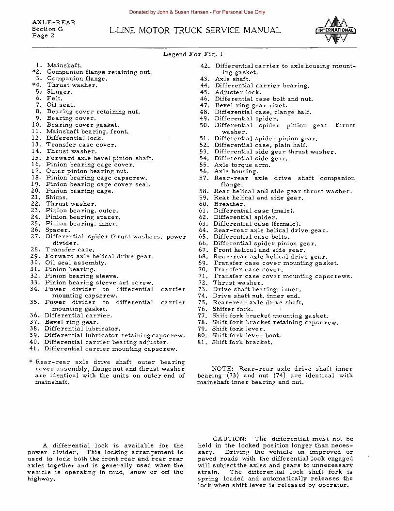
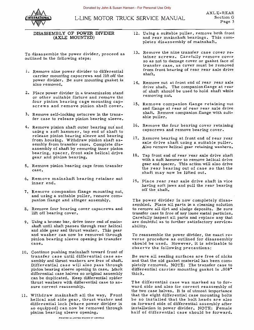

Donated by John amp Susan Hansen - For Personal Use Only
AXLE-REAR L-LINE MOTOR TRUCK SERVICE MANUAL Section H
Page 1
ELECTRIC SHIFT (EATON) USED ON EATON AND TIMKEN TWO-SPEED AXLES
Shifting motor
assembly
Fig I - Electric Shift Unit Mounted on two speed axle
Description
The electric shift device consists in the main of an electrically operated shifting fork and shifting unit located on the two-speed axle (Fig 1) The shift fork is activated by a twoshydirectional coil spring and lever assembly (Figs 6 and 7) The purpose of this spring and lever asseInbly is to rrove the shiftfork quickshyly into the high or low speed position when gear load is InoInentarily reInoved froIn the differential
The actual shifting or gear moveInent is perforIned by the coil spring located in the housing of the electric shift unit The coil spring which perforIns the shift Inust be placed under tension or in a loaded state before gear shift can be accomplished This is provided for by a reversible electric Inotor which drives a power screw which in turn actuates a drive nut in either direction Trunnions on either side of the drive nut engage slots in the spring lever l1oveInent of the lever in either direcshytion energizes the spring which perforIns the shifting InoveInent
The control of the electric shift unit is by means oia two-way switch located on the transshyInission gear shift lever (Figs 2 3 and 4) Moving control button up or down causes Inotor at axle shift unit to rotate in either direction A UInit switch located in the electric shift unit
Switch receptacle
(part of wire I harness)
Fig 2 - Electric Shift Unit Two Way Control Switch
(Figs 3 and 6) opens the circuit and stops the Inotor when the shifting spring is fully enershygized Any time thereafter the shift is COInshypleted by the energy of the spring when torque is InoInentarily released froIn the differential gears either by releasing the clutch or closing the throttle
A two-speed adapter electrically operated is located at the speedoIneter and is wired in series with the ignition switch (Figs 2 3 and 5) The balance of the electrical circuit is also wired in series with the ignition switch thereby preventing any closed electrical cir shycuits in the systeIn when the truck is idle and the ignition switch is turned to the OFF poshysition
Gear shift
A D To lever switch Shift motor
Circuit hreaker
ignition switch
Automatic - switch
Red B -----(-----J
------- Black C Amiddot22525
Fig 3 - Electric Shift Circuit Diagram PRINTEO IN t)NITED STATes OF AMRICA
A-22894
Donated by John amp Susan Hansen - For Personal Use Only
AXLE-REAR Section H L-UNE MOTOR TRUCK SERVICE MANUAL Page 2
Shifting motorTwo-way assemblyswitch
A-22895
Fig ~ - Illustration Of Electric Shift Parts
The system is further protected by a selfshyresetting circuit breaker which becomes operative when normal current flow continues for a period longer than is required to complete a shift or in case of an overload or direct short
Details of the various units of the Electric Shift their function and the servicing of each fonows
The switch (Fig 2) with which the operator controls the axle is located on the transmission gear shift lever
This control switch has two positions -- up and down Three wires are connected to the switch When the selector button of the switch is up the battery wire (A -- Fig 3) is conshynected to wire (B -- Fig 3) leading to one field of the motor in the axle shift unit proper
When the button is down the battery wire is connected to wire (C -- Fig 3) leading to the other field of the axle shift unit motor and also to the speedometer adapter
As shown in Fig 2 the control switch is connected to the harness or wiring system by plugging into the three-pronged connector which is part of the harness The switch is removable by slipping the rubber boot up to the knob and pulling apart
Wiring System
The wiring system or harness as shown in Fig 3 has four terminals Two of them (b) and (c) in a double line run to the axle shift unit on the axle Of these the longer red one is conshynected to the bottom terminal and the shorter black one is connected to the top terminal The short single black wire (c) is connected to the speedometer adapter and the green wire (a) is connected to the circuit breaker Wire (d) connects the copper stud of the circuit breaker to the cold side of the ignition switch The
Fig 5 - Speedometer Two-Speed Adapter
circuit breaker protects the system in the event of a short circuit Should a short circuit occur it will open the circuit until the trouble has been corrected
Speedometer Adapter
The speedometer adapter (Fig 5) compenshysates for variations in the speed of the drive shaft between high and low-speed range of the axle
This adapter is held in the high range by a spring and in the low range by an electro magshynet The inner mechanism is lubricated and sealed for life but the two shaft ends should occasionally receive a small amount of light oil at the oil-wick cups
Axle Shift Unit
This unit shifts the axle into high or lowshyrange Fig 6 shows the axle shift unit in the high range of the axle In this position wire (b) (Fig 3) carries current to one field of the motor (6) (See Fig 20 for Part Identification) so that the armature and drive screw (20) turn in a clockwis e direction and move the nut down When the nut has traveled a sufficient distance to wind the spring (23) a contact bumper on the nut breaks an electrical connection on the automatic switch (17) so that the motor is no longer energized and the armature stops rotatshying To make sure that the nut cannot travel back on the screw due to vibration a ball screw detent spring (Fig 12) mounted on the cover (26) holds the nut at the end of its travel on the screw The nut moves the spring winding lever (24) down which pivoting on the pin (21) winds the tors ion spring (23) for high Thus an inshycreased load is put on the spring and in this position the axle is ready to snap into the high speed ratio as soon as the load on the axle gears is relieved The torsion spring is assembled in the unit so that it is under 45 to 65 pounds pressure depending on the size of the axle When the spring winding lever is moved so that the spring is wound the pressure
Donated by John amp Susan Hansen - For Personal Use Only
AXLE-REAR Section HL-LINE MOTOR TRUCK SERVICE MANUAL
Page 3
screw
Limit switch
Fig 6 - Axle Shift Unit In High-Range Position
Lever assembly
Power screw
Drive ---- shynut
Limit switch
Amiddot22893
Fig 7 - Axle Shift Unit In low-Range Position
of the spring is raised tofrom 90 to 135 pounds again depending on axle size
This additional means is us ed to shift the axle and when the shift is completed the ends of the spring come together leaving the origishynal tension of 45 to 65 pounds on the spring This preload tension holds the axle in either gear
Shift To Low
When the button is pushed down the motor is energized so that the screw moves counter clockwise and the nut travels to the top windshying the spring for a shift to low in the same manner as before
SERVICE AND TROUBLE SHOOTING
General Information
1pound the electric shift should fail to operate properly the trouble should first be located A very handy tool for this is a test light conshysisting of a light bulb either 6 or 12 volts depending on the electrical system of the truck with two wires a few feet long and small battery clips on the ends Refer now to the wiring diagram Fig 3 and first connect the test light to Point (d) on the circuit breaker under the dash or hood depending on the test light to ground Turn on ignition switch or accessory switch in the case of a diesel and the light should show If it fails to light at this point there is a poor connection or broken wire between the ignition switch and circuit breaker Next connect test light to Point (a) on the circuit breaker -- Fig 3 -- and again the light should show If it fails to show imshymediately watch the light carefully and listen to the circuit breaker for a minute to see if it is flashing off and on The light should stay on continuously at this point If it flashes off and on or you hear the breaker clicking it indicates that too much current is flowing and the circuit breaker is opening This is due either to a short circuit or the motor in the shift unit not being free to run To detershymine which of these it is remove the two wires (b) and (c) from the axle shift unit and recheck If the light still flashes off and on or you still hear the breaker clicking it is due to a short in the harness but if the light now stays on continuously the trouble is in the shaft unit
If there is no light at all at this point and the circuit breaker cannot be heard clicking disconnect the green wire from terminal (a) Fig 3 and again clip the test light to terminal (a) post on the circuit breaker If the light fails to show here and did show on terminal (d) the circuit breaker is bad and should be reshyplaced
If the test light glowed normally at point (a) next remove the two wires (b) and (c) from the axle shift unit and connect a test light wire to one of these wires and the other test light wire to ground The red shift unit wire should light the light only in high gear or up position on the gear shift lever switch andthe black wire should light the light only in the low gear or down position of the gear shift lever switch If the light fails to glow in either of the above tests it indicates a broken circuit in the harshyness or gear shift lever switch If both wires light the test light in one position of the gear shift lever switch it indicates a short circuit in the harness or gear shift lever switch
Next connect the test light to the speedomshyeter adapter terminal (c) and ground Here
FRINTED IN UNITpoundD SrATE$ 0 AMEAICA
Donated by John amp Susan Hansen - For Personal Use Only
AXLE-REAR Section H L-UNE MOTOR TRUCK SERVICE MANUAL Page 4
the light should glow in the low gear or down position of the gear shift lever switch only 1pound it fails to glow it indicates a broken circuit in the harness or gear shift lever switch
These checks above will quickly locate the trouble When checking the harness for short or open circuits watch for broken insulation and do not overlook ~ gear shift ~ switch which can best be tested by substituting a new one in its place
If the vehicle shifts normally but the speedometer adapter fails to operate properly make the above check with the test light to see if it is getting current in the low range and if it is replace the adapter When the trouble has been traced to the shift unit disassemble as shown under disassembly and inspect the parts carefully All parts can be washed in cleaning solvent except the motor
When inspecting the parts most failures will be readily apparent however a few assemblies should be checked as follows
Automatic Switch
The automatic switch (17) Fig 20 (servshyiced only as an assembly) should have clean free moving points which close firmly under spring tension
Drive Screw
The drive screw (20) Fig 20 (serviced only as an assembly) should turn freely by roshytating the s crew while holding the nut When the nut gets to the end of the screw the screw can continue to turn but the nut should not jam or run off the end By turning the screw in the opposite direction the nut will go to the other end and stop as before while the screw can continue to be turned
The fiber bumper in the nut should be a tight press fit Be sure in assembly that this fiber bumper is in towarcfthe switch
Motor
The motor (6) Fig 20 (serviced only as an assembly) is reversible so that with the motor housing connected t6 one battery terminal and either one of the two motor wires connected to the other battery terminal the motor will run in one direction With the other motor wire connected to the battery the motor will run in the opposite direction The motor has a stall torque of approximately 6 lbs The way to check this motor is to put a small crescent wrench on the rectangular drive on the armashyture shaft Hold the wrench in one hand hold the motor itself firmly in the other hand or in a vis e and then connect one motor wire to a battery terminal and connect the motor housing
to the other battery terminal The wrench should then tend to turn with a torque or pull of about 6 lbs Allow the wrench to turn very slowly making sure that this pull or torque is present the full 3600 turn of the wrench If one armature winding of the motor is burned out this torque will disappear for a small part of the 360 0 bull While making this test care should be taken not to overheat the motor This motor is lubricated and sealed for life
Rubber Diaphragm
The rubber diaphragm between the shift unit and the carrier assembly which can be seen in Fig 8 under disassembly should be in good condition and a tight fit over the shift fork This diaphragm seals off axle lubricant from the shift unit
NOTE During reassembly extreme care should be taken not to allow any dirt to enter the axle shift unit
For correct positioning of diaphragm refer to lettering printed on its face
Lubrication
The speedometer adapter requires no more attention than would be required by the speedshyometer or the speedometer cable Several drops of light oil should be applied in the proshyvided oil-wick cups
On the axle shift unit there is an oil filler plug (27) so marked provided in the front cover (26) near the bottom Upon installation the unit should be filled level with lubricant and should be checked every 10000 miles or 3 months whichever comes first to maintain this level
The lubricant us ed should be SAE 10 motor oil except where temperatures below 00 F will be encountered in which case use 3 parts SAE 10 motor oil to 1 part kerosene This cold weather mixture can safely be used in tempershyatures up to 320 F
To change lubricant remove front cover (26) and drain Whenever front cover is reshymoved care should be taken not to allow any dirt to enter
AXLE UNIT DISASSEMBLY
The axle unit (Fig 1) is removed from the differential carrier for disassembly and servshyicing as follows
Donated by John amp Susan Hansen - For Personal Use Only
AXLE-REAR Section HL-UNE MOTOR TRUCK SERVICE MANUAL
Page 5
Axle bift- shyusembly
fork notch
A22648
Fig 8 - Remove shift housing to carrier stud nuts and lockwashers and lift off shift unit Upon reassembly the swivel block must engage the shift fork notch
Fig 9 - Remove lock nuts and two wires from housing In reassembling the long or rod wire goes to the bottom terminal
Power screw
Limit Iwitch
Fig II - After removal of cover note that nut and lever assembly will be at either top or bottom of screw depending upon position in which the shift button was last used
Fig 12 - By turning drive screw run nut from either top or bottom position to center of screw IMPORTANT This step is essential to prevent damage to drive nut contact bumper loshycated in center of lower or inner trunnion The nut must be inthe center position upon assembly also
Trunnion ( contact bumper
Bearing cover
Fig 10 - Remove cover screws lockwashers Fig 13 - Pullout pivot pin and remove lever cover and gasket Drain lubricant from housing assemb I y
PRINTED IN UNITED STATES OF MERICA
Donated by John amp Susan Hansen - For Personal Use Only
AXLE-REAR Section H L-L1NE MOTOR TRUCK SERVICE MANUAL Page 6
NOTE When reassembling lever assemshybly make certain that the contact bumper on nut is toward the switch
A-22644
Fig I~ - Remove drive screw bearing cover and push down on screw assembly until bearing is free of housing Insert screwdriver in drive slot of screw and remove bearing retainer nut and bearing
Fig 15 - Remove two lock nuts from switch tershyminals and remove wires
Fig 17 - Remove jam nuts (switch retainer nuts) and fiber washers from back side of housshying Remove switch center screw and I ift out switch assembly
Lever and Spring Assembly
Good practice is to perform the disassemshybly and reassembly of the lever and spring unit only when necessary to replace one of the parts
Turn lever This lever
Fig 18 - Place lever assembly in vise as shown Motor cover Turn spring winding lever clockwise and pul I
Amiddot22649 then al low spring to unwind This operation Fig 16 - Remove three motor retainer screws will permit disassembly of the leversandspring remove cover and gasket and pul I motor assemshy IMPORTANT Do not disassemble this unit unti I bly out of housing necessary to replace one of the parts
Donated by John amp Susan Hansen - For Personal Use Only
AXLE-REAR Section HL-UNE MOTOR TRUCK SERVICE MANUAL
Page 7
End of spring to be located
Fi g 19
1 When reassembling the spring and levers locate parts as shown (Fig 19) Turn lever and spring clockwise bringing end of spring around end of lever nearest vise Push end of spring into notch of actuating lever nearest vise This will preload spring
Reassembly of the axle shift unit is the reverse of disassembly
SHIFTING INSTRUCTIONS FOR EATON TWO-SPEED AXLE ELECTRIC SHIFT
TO SHIFT INTO LOW-SPEED RATIO
1 Keep accelerator pedal down push button down
Z To complete shift disengage and reengage clutch as quickly as possible holding accelerator pedal down or release and reopen accelerator as quickly as possible
TO SHIFT INTO HIGH-SPEED RATIO
1 Keep accelerator pedal down pull button up
Z To complete shift release accelerator and pause until shift is completed
SPLIT-SHIFTING
To shift to next higher gear in the transshymission and at the same time from high to low speed axle make the transmission shift in usual way and just before engaging clutch push the button down
To shift to next lower gear in the transshymission and at the same time from low to highshyspeed axle pull the button up then complete the transmission shift in usual way
IMPORTANT
1 Always keep accelerator down when conshytool button is moved except when split shyshifting to low-speed ratio
2 For best results start loaded trucks in low-speed ratio
PRINTEO IN UNITEO STATES OF AMERICA
Donated by John amp Susan Hansen - For Personal Use Only
AXLE-REAR Section H LmiddotLINE MOTOR TRUCK SERVICE MANUAL Page 8
1 Screw with lockwasher (motor cover to housing)
2 Elastic stop nut (motor to cover) 3 Motor cover cable clip 4 Motor support and cover 5 Motor support and cover gasket 6 Electric motor assembly 7 Electric motor grommet 8 Shift motor housing 9 Jam nut (automatic switch terminal-shy
outside) 10 Fibre washer (automatic switch termishy
nal -- outside) 11 Bushing (automatic switch terminal hole
in housing) 12 Bearing with snap ring 13 Bearing lock nut 14 Bearing cover gasket 15 Bearing cover
f1-__-1IIr--6
amp-12 --13
~I ~IS I- 16
2S
8middot4746
Fig 20 - Electric Shift Parts Identification List And Illustrations
16 Screw with lockwasher (bearing cover to housing)
17 Automatic switch terminal screws and base gasket assembly
18 Flat head screw (automatic switch to housing -- inside)
19 Elastic stop nut (automatic switch termishynals -- inside)
20 Drive screw assembly 21 Spring winding and shift fork actuating
lever shaft 22 Shift fork actuating lever assembly 23 Torsion spring 24 Spring winding lever assembly 25 Shift housing cover gasket 26 Shift housing cover 27 lI8 pipe plug 28 Screw with lockwasher (shift housing cover
to housing)
Donated by John amp Susan Hansen - For Personal Use Only
BODIES CABS amp COWLS
L-LINE MOTOR TRUCK SERVICE MANUAL Index Page 1
BODY AND CAB GROUP
SECTION A
Cab door glassbullbullbullbullbullbull
Cab door glass window regulator
Cab door weather strips bullbull
Cab door glas s window channel
Cab rear window glass
Panel body rear door glass
Windshieldsbullbullbullbullbull
Cab door vent glass window bull
Cab door latch and remote control bull
Removal of outside door handlebullbull
Installation of outside door handle bull
Lock cylinders and keys
Ignition switch
Door lock
Cab door removal
Cowl ventilator
Seat adjuster
Cab mountings bull
Hood assembly
Fender and radiator grille
Body mountings bullbull
Fifth wheel mounting
Panel and pick-up body mountings
Page
1 2
2 3
3
3 4 5
5 6
6
6 7 8 9
9 10
11 12 13
13
13
13 14
14
14
14 15
15 16
16 17
17 18 19 20
20 21
21 22 2324
24
25 26
27
Windshield wiper bullbullbullbullbullbullbull 28 to 33
PRINTED iN UNIYED STATpoundS OF AMERICA
Donated by John amp Susan Hansen - For Personal Use Only
Donated by John amp Susan Hansen - For Personal Use Only
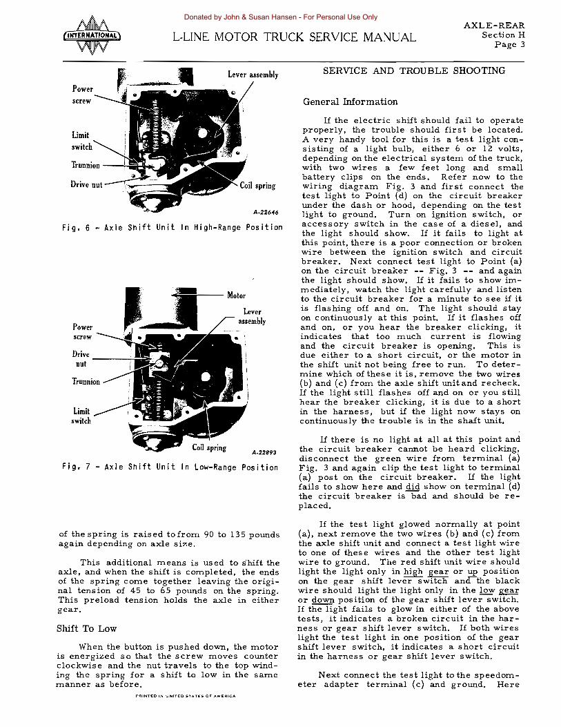

AXLE-REAR Section HL-UNE MOTOR TRUCK SERVICE MANUAL
Page 5
Axle bift- shyusembly
fork notch
A22648
Fig 8 - Remove shift housing to carrier stud nuts and lockwashers and lift off shift unit Upon reassembly the swivel block must engage the shift fork notch
Fig 9 - Remove lock nuts and two wires from housing In reassembling the long or rod wire goes to the bottom terminal
Power screw
Limit Iwitch
Fig II - After removal of cover note that nut and lever assembly will be at either top or bottom of screw depending upon position in which the shift button was last used
Fig 12 - By turning drive screw run nut from either top or bottom position to center of screw IMPORTANT This step is essential to prevent damage to drive nut contact bumper loshycated in center of lower or inner trunnion The nut must be inthe center position upon assembly also
Trunnion ( contact bumper
Bearing cover
Fig 10 - Remove cover screws lockwashers Fig 13 - Pullout pivot pin and remove lever cover and gasket Drain lubricant from housing assemb I y
PRINTED IN UNITED STATES OF MERICA
Donated by John amp Susan Hansen - For Personal Use Only
AXLE-REAR Section H L-L1NE MOTOR TRUCK SERVICE MANUAL Page 6
NOTE When reassembling lever assemshybly make certain that the contact bumper on nut is toward the switch
A-22644
Fig I~ - Remove drive screw bearing cover and push down on screw assembly until bearing is free of housing Insert screwdriver in drive slot of screw and remove bearing retainer nut and bearing
Fig 15 - Remove two lock nuts from switch tershyminals and remove wires
Fig 17 - Remove jam nuts (switch retainer nuts) and fiber washers from back side of housshying Remove switch center screw and I ift out switch assembly
Lever and Spring Assembly
Good practice is to perform the disassemshybly and reassembly of the lever and spring unit only when necessary to replace one of the parts
Turn lever This lever
Fig 18 - Place lever assembly in vise as shown Motor cover Turn spring winding lever clockwise and pul I
Amiddot22649 then al low spring to unwind This operation Fig 16 - Remove three motor retainer screws will permit disassembly of the leversandspring remove cover and gasket and pul I motor assemshy IMPORTANT Do not disassemble this unit unti I bly out of housing necessary to replace one of the parts
Donated by John amp Susan Hansen - For Personal Use Only
AXLE-REAR Section HL-UNE MOTOR TRUCK SERVICE MANUAL
Page 7
End of spring to be located
Fi g 19
1 When reassembling the spring and levers locate parts as shown (Fig 19) Turn lever and spring clockwise bringing end of spring around end of lever nearest vise Push end of spring into notch of actuating lever nearest vise This will preload spring
Reassembly of the axle shift unit is the reverse of disassembly
SHIFTING INSTRUCTIONS FOR EATON TWO-SPEED AXLE ELECTRIC SHIFT
TO SHIFT INTO LOW-SPEED RATIO
1 Keep accelerator pedal down push button down
Z To complete shift disengage and reengage clutch as quickly as possible holding accelerator pedal down or release and reopen accelerator as quickly as possible
TO SHIFT INTO HIGH-SPEED RATIO
1 Keep accelerator pedal down pull button up
Z To complete shift release accelerator and pause until shift is completed
SPLIT-SHIFTING
To shift to next higher gear in the transshymission and at the same time from high to low speed axle make the transmission shift in usual way and just before engaging clutch push the button down
To shift to next lower gear in the transshymission and at the same time from low to highshyspeed axle pull the button up then complete the transmission shift in usual way
IMPORTANT
1 Always keep accelerator down when conshytool button is moved except when split shyshifting to low-speed ratio
2 For best results start loaded trucks in low-speed ratio
PRINTEO IN UNITEO STATES OF AMERICA
Donated by John amp Susan Hansen - For Personal Use Only
AXLE-REAR Section H LmiddotLINE MOTOR TRUCK SERVICE MANUAL Page 8
1 Screw with lockwasher (motor cover to housing)
2 Elastic stop nut (motor to cover) 3 Motor cover cable clip 4 Motor support and cover 5 Motor support and cover gasket 6 Electric motor assembly 7 Electric motor grommet 8 Shift motor housing 9 Jam nut (automatic switch terminal-shy
outside) 10 Fibre washer (automatic switch termishy
nal -- outside) 11 Bushing (automatic switch terminal hole
in housing) 12 Bearing with snap ring 13 Bearing lock nut 14 Bearing cover gasket 15 Bearing cover
f1-__-1IIr--6
amp-12 --13
~I ~IS I- 16
2S
8middot4746
Fig 20 - Electric Shift Parts Identification List And Illustrations
16 Screw with lockwasher (bearing cover to housing)
17 Automatic switch terminal screws and base gasket assembly
18 Flat head screw (automatic switch to housing -- inside)
19 Elastic stop nut (automatic switch termishynals -- inside)
20 Drive screw assembly 21 Spring winding and shift fork actuating
lever shaft 22 Shift fork actuating lever assembly 23 Torsion spring 24 Spring winding lever assembly 25 Shift housing cover gasket 26 Shift housing cover 27 lI8 pipe plug 28 Screw with lockwasher (shift housing cover
to housing)
Donated by John amp Susan Hansen - For Personal Use Only
BODIES CABS amp COWLS
L-LINE MOTOR TRUCK SERVICE MANUAL Index Page 1
BODY AND CAB GROUP
SECTION A
Cab door glassbullbullbullbullbullbull
Cab door glass window regulator
Cab door weather strips bullbull
Cab door glas s window channel
Cab rear window glass
Panel body rear door glass
Windshieldsbullbullbullbullbull
Cab door vent glass window bull
Cab door latch and remote control bull
Removal of outside door handlebullbull
Installation of outside door handle bull
Lock cylinders and keys
Ignition switch
Door lock
Cab door removal
Cowl ventilator
Seat adjuster
Cab mountings bull
Hood assembly
Fender and radiator grille
Body mountings bullbull
Fifth wheel mounting
Panel and pick-up body mountings
Page
1 2
2 3
3
3 4 5
5 6
6
6 7 8 9
9 10
11 12 13
13
13
13 14
14
14
14 15
15 16
16 17
17 18 19 20
20 21
21 22 2324
24
25 26
27
Windshield wiper bullbullbullbullbullbullbull 28 to 33
PRINTED iN UNIYED STATpoundS OF AMERICA
Donated by John amp Susan Hansen - For Personal Use Only
Donated by John amp Susan Hansen - For Personal Use Only

Donated by John amp Susan Hansen - For Personal Use Only