International Gas Union Research Conference 2011 Failure ...members.igu.org/old/IGU...
14
International Gas Union Research Conference 2011 Failure of Field Joint Coating under Soil Stress Main author YoungGeun Kim South Korea
Transcript of International Gas Union Research Conference 2011 Failure ...members.igu.org/old/IGU...

International Gas Union Research Conference 2011
Failure of Field Joint Coating under Soil Stress
Main author
YoungGeun Kim
South Korea

ABSTRACT
Field joint coating failure has been known for site of corrosion damage in many gas transmission
pipelines. The unfriendly environment for coating application in the field has been regarded as a
cause of coating failure. In this study the results of coating failure mechanism analysis and the
approach to understand this problem was reported. The stress on the coating of buried pipe was
analyzed with numerical analysis. The effect of burial procedure on the stress of the coating was
studied at various conditions. The shape of wrinkled coating at the girth weld shows the evidence
of soil stress concentration at the coating layer. It was shown that the compaction step was
important for the soil stress control on the pipe. The step-wise compaction could lower the level of
stress. And the failure mode observed in the field implies that the tensile hoop stress at the field
join coating could reduce the failure by wrinkle.

TABLE OF CONTENTS
1. Abstract
2. Body of Paper
3. References
4. List Tables
5. List of Figures
1. INTRODUCTION
Prevention of failure and maintaining of integrity of pipeline is very important part of operation.
As corrosion is a major cause of failure of pipeline, corrosion control is a main concern of gas
transmission network. Coating of pipe is usually coated in the plant. However, coating on the girth
weld of pipe should be done in the field. The field joint coating applied on girth weld areas after
welding must be compatible with the plant coating and should resist to construction and service
conditions. ISO 13623 recommends that performance of field joint coatings should be as good as
or even better than the performance of plant-applied coatings of pipes.(1) However the application
environment in the field is more unfavorable for the quality control coating. Many failures occur at
the field applied coating.(2,3,4) The author’s company also experienced failures of field applied
coating. PE (Polyethylene) based heat shrinkable sleeves is used in the authors company. Plant
applied coating is mainly extruded PE.
In this study the results of coating failure mechanism analysis have been done. The stress on the
coating of buried pipe was analyzed with numerical analysis. The effect of burial procedure on the
stress on the coating was studied at various conditions. And the failure mode observed in the field
was compared with the calculation results to confirm the mode of failure.
2. CASE HISTORY
Many metal loss found by the MFL (Magnetic Flux Leakage) pig inspection was found to be
related with the coating failure of the heat shrinkable sleeves.(5) The coating failure of the pipe was
observed as wrinkle at the lower part of the pipe around 6 o’clock position.(Figure 1,2) And the
coating failure at the girth weld joint is often leads to severe corrosion related MIC
(Microbiologically Influenced Corrosion).(Figure 3) This type of coating failure was reported
frequently in Korea. We found that about 90% of metal loss were related with this type of coating
failure. The wrinkle at the bottom of the pipe is unusual in other country. The reason of the failure
was sought in this work.
Figure 1. Coating failure at the field applied coating

Figure 2. Wrinkles at the field applied coating
Figure 3. Corrosion of Pipe at the field applied coating failure
3. SIMULATION OF CONSTRUCTION PROCEDURE
In this country most of onshore transmission pipelines were welded and coated in the trench as
many pipeline is built along the roads and excavation of roadside are allowed only for short length
to minimize traffic congestion. So the backfill soil is poured from above using excavator during
backfilling job. The backfill materials used were usually river sand. The standard construction
procedure prescribes step-by-step compaction of back-fill soil. However the precise procedure was

sometimes disobeyed by the contractor. It is very common to back-fill the trench in a single step.
The initial density of soil was analyzed using particle flow code in 2 dimensions (PFC2D of
ITASCA). Following results shows the typical calculation results of the analysis. The particles falling
from the above will fill the space around the pipe in the trench.(Figure 4)
Figure 4. Simulation of Back-filling with Particle Flow Code
The void fraction around the pipe in a case varied with the position.(Figure 5) The results were
shown in Table 1. The void fraction at the invert position was highest and that at the haunch
position was still high compared to spring line position. This phenomenon might provide the cause
of soil flow around the pipe. And the flow of soil will induce shear stress on coating of the lower part
of the pipe. These results explain the observed coating failures (Figure 1, 2).
Figure 5. Particle Distribution around the Pipe from Particle Flow Analysis
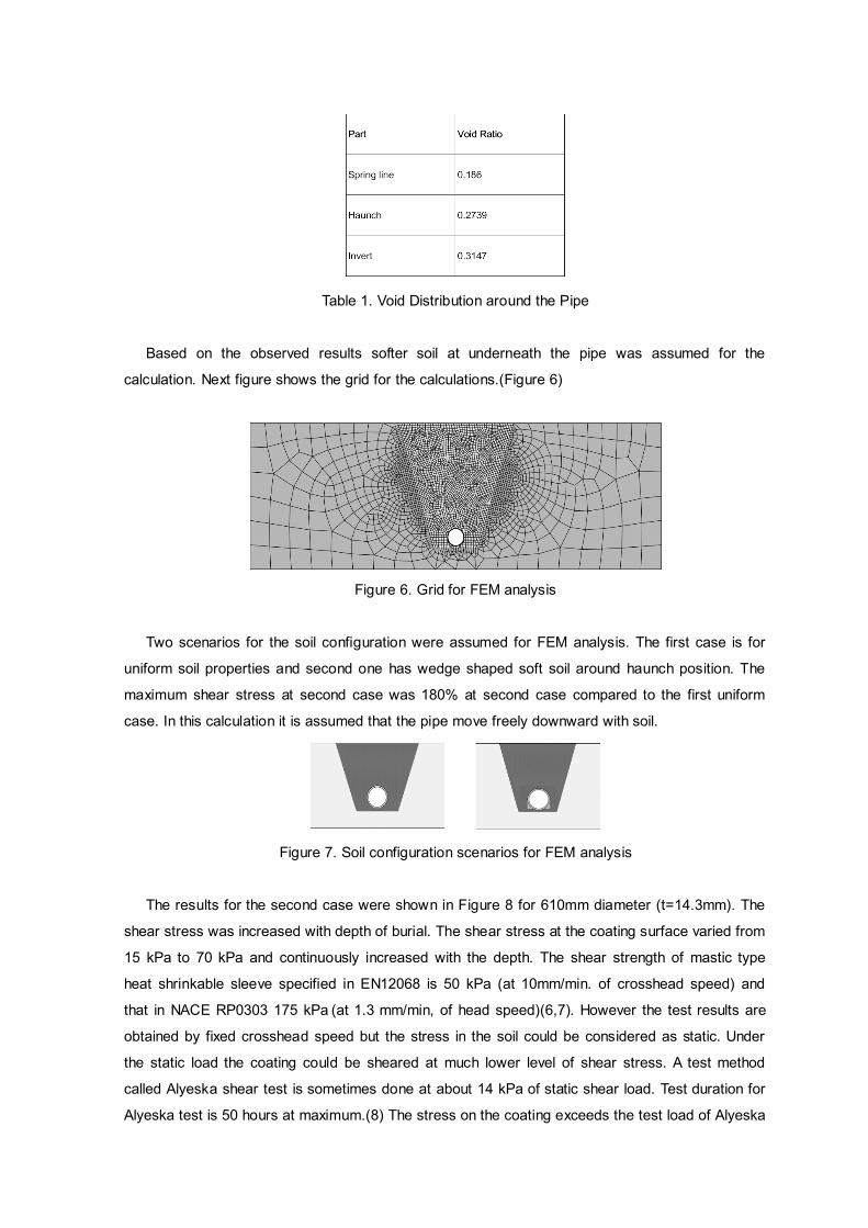
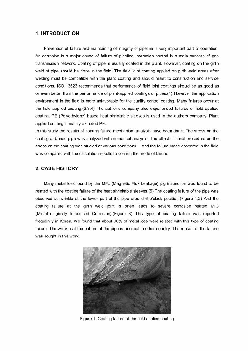
Table 1. Void Distribution around the Pipe
Based on the observed results softer soil at underneath the pipe was assumed for the
calculation. Next figure shows the grid for the calculations.(Figure 6)
Figure 6. Grid for FEM analysis
Two scenarios for the soil configuration were assumed for FEM analysis. The first case is for
uniform soil properties and second one has wedge shaped soft soil around haunch position. The
maximum shear stress at second case was 180% at second case compared to the first uniform
case. In this calculation it is assumed that the pipe move freely downward with soil.
Figure 7. Soil configuration scenarios for FEM analysis
The results for the second case were shown in Figure 8 for 610mm diameter (t=14.3mm). The
shear stress was increased with depth of burial. The shear stress at the coating surface varied from
15 kPa to 70 kPa and continuously increased with the depth. The shear strength of mastic type
heat shrinkable sleeve specified in EN12068 is 50 kPa (at 10mm/min. of crosshead speed) and
that in NACE RP0303 175 kPa (at 1.3 mm/min, of head speed)(6,7). However the test results are
obtained by fixed crosshead speed but the stress in the soil could be considered as static. Under
the static load the coating could be sheared at much lower level of shear stress. A test method
called Alyeska shear test is sometimes done at about 14 kPa of static shear load. Test duration for
Alyeska test is 50 hours at maximum.(8) The stress on the coating exceeds the test load of Alyeska

test. The analysis results suggest that the shear stress of construction in the trench could induce
shearing of the pipeline coating.
Figure 8. Variation of maximum shear stress with burial depth at 610 mm diameter pipe
4. FIELD EXPERIMENT ACCORDING TO STANDARD CONSTRUCTION
PROCEDURE
The field experiment was designed to find the relation between the coating application procedure
and the coating performance. Heat shrinkable sleeve was applied on the 760mm diameter PE
coated pipe. The coating application conditions were varied to find the relation between the coating
application condition and coating performance. The variables were preheating temperature (40℃
and 60℃), the shrinking margin of the sheet before shrinking, the surface temperature before back-
filling (70℃, 40℃, 70℃ and ambient temperature(about 10℃))and backfilling method ( back fill to
the top of the pipe in one step and back fill to the bottom of the pipe before full back filling).

6060606060606060606060604040404040404040404040406060606060606060606060606060606060606060pre- heating
(℃)
303030301515151555553030303015151515555555555555555555555555margin of sheet (cm)
AmbAmbAmbAmb....
(24hr)(24hr)(24hr)(24hr)
AmbAmbAmbAmb....
(24hr)(24hr)(24hr)(24hr)
AmbAmbAmbAmb....
(24hr)(24hr)(24hr)(24hr)
AmbAmbAmbAmb....
(24hr)(24hr)(24hr)(24hr)
AmbAmbAmbAmb....
(24hr)(24hr)(24hr)(24hr)
AmbAmbAmbAmb....
(24hr)(24hr)(24hr)(24hr)
AmbAmbAmbAmb....
(24hr)(24hr)(24hr)(24hr)
AmbAmbAmbAmb....
(24hr)(24hr)(24hr)(24hr)30 30 30 30 ℃℃℃℃40404040℃℃℃℃70707070℃℃℃℃back f ill
temperature
1 1 1 1 stepstepstepstep
1 1 1 1 stepstepstepstep
1 1 1 1 stepstepstepstep
1 1 1 1 stepstepstepstep
1 1 1 1 stepstepstepstep
1 1 1 1 stepstepstepstep
2 step2 step2 step2 step1 1 1 1
stepstepstepstep1 1 1 1
stepstepstepstep1 1 1 1
stepstepstepstep1 1 1 1
stepstepstepstep
Back f ill
method
Group C
PreHeat and margins of sheet
Group B
Standard
CCCC---- 6666CCCC---- 5555CCCC---- 4444CCCC---- 3333CCCC---- 2222CCCC---- 1111BBBB---- 1111AAAA---- 3333AAAA---- 2222AAAA----
1.21.21.21.2
AAAA----
1.11.11.11.1No.
Group A
Back f ill temperature
Table 2. Summary of variables for the field test
All of the application was done above ground.(Figure9) It means that the condition for the working
were very good to apply and to inspect every surface of the coating. The heating of the surface was
uniform. After application of the coating the pipes were buried to the depth of 1.5 m to the top of the
pipe. The typical value of the commercial mastic heat shrinkable sleeve is about 200 kPa.
Figure 9. Coating Application for Field Test of Coating Performance

Figure 10. Excavation of the Buried Pipe for Field Test of Coating Performance
After 205 days after installation the pipes were excavated to inspect any imperfection.(Figure 10)
Every coating was found to be sound except small wrinkles in circular direction. It was believed that
the redistribution of hot mastic adhesive during curing induced the circular wrinkles. No severe
winkles related to local adhesion failure was found in any condition. The coating defects which was
found in the in-service pipe was not reproduced in this field test. There are several possibility in
interpreting the results of this field test. The first implication is that the coating product with
adequate shear strength could resist normal shear stress during construction and service. The
second one is that the bad workmanship or the use of wrong backfill materials or limited working
condition in the trench is related to the coating failure.
Figure 11. Small Wrinkles on the Surface of Excavated Buried Pipe (C group-5)
5. SUMMARY
Some cases of coating failure was reported in this work. The shape of wrinkled coating at the
girth weld shows the evidence of soil stress concentration at the coating layer. In this study the

results of coating failure mechanism analysis and the approach to understand this problem was
reported. The stress on the coating could be increased with the development of low density soil
part during the construction process. In some cases the imposed shear stress could be higher than
the specified minimum shear strength of the heat shrinkable sleeves. The wrinkle which was found
at the in-service pipe was not reproduced in this test when the pipe was lowered after installation of
the joint coating. It is believed that the installation procedure has relationship with the wrinkle
development.
REFERENCES
1. ISO 13623-2000, Petroleum and Natural Gas pipelines – Pipeline transportation sysems
2. Ersoy, Daniel and O’Brien, Mike. (2005)., Field Applied Coatings(for FBE Mainline Coated
Pipe) Evaluation, Gas Technology Institute, Des Plaines, IL., Project No. 15104
3. Moosavi , Ali N and Al-Bufalah, Salah J (2004). Pipeline Coatings for Harsh Environments ,
Proceedings, Corrosion2004, NACE International, Paper No. 04038
4. Buchanan, Robert and Tacoma, Emerson, Innovations in Field Joint Coatings to Meet
Rigorous Specifications for Offshore Pipelines, Proceedings, Corrosion2004, NACE International,
Paper No. 04020
5. Li, S.Y., Kim, Y.G., Jeon, K.S., Kho,Y.T. and Kang, T., (2001), Microbiologically Influenced
Corrosion of Carbon Steel Exposed to Anerobic Soil Corrosion, Corrosion, 57, 9, p815
6. EN 12068, Cathodic protection-External organic coatings for the corrosion protection of buried
or immersed steel pipelines used in conjunction with cathodic protection-Tapes and shrinkable
materials.
7. NACE Standard RP0303-2003, Field-Applied Heat-Shrinkable Sleeves for Pipelines:
Application, Performance, and Quality Control
8. TP-206, Alyeska Test - Tape Shear Test

LIST TABLES
Table 1. Void Distribution around the Pipe
Table 2. Summary of variables for the field test

LIST FIGURES
Figure 1. Coating failure at the field applied coating
Figure 2. Wrinkles at the field applied coating
Figure 3. Corrosion of Pipe at the field applied coating failure
Figure 4. Simulation of Back-filling with Particle Flow Code
Figure 5. Particle Distribution around the Pipe from Particle Flow Analysis
Figure 6. Grid for FEM analysis
Figure 7. Soil configuration scenarios for FEM analysis
Figure 8. Variation of maximum shear stress with burial depth at 610 mm diameter pipe
Figure 9. Coating Application for Field Test of Coating Performance
Figure 10. Excavation of the Buried Pipe for Field Test of Coating Performance
Figure 11. Small Wrinkles on the Surface of Excavated Buried Pipe (C group-5)