DIRECT NUMERICAL SIMULATION DIRECT NUMERICAL ...direct numerical simulation direct

International Engineering Research Journal Special Edition PGCON-MECH-2017
1
International Engineering Research Journal Numerical simulation and Experimental investigation of Combo Washer-Dryer
Vilas Raut†, V.N. Kapatkar‡ and P.W. Deshmukhϯ
†Mechanical Engg Dept, Sinhgad College of Engg , University of Pune, Pune, Maharashtra, India ‡Prof. Mechanical Engg Dept, Sinhgad College of Engg , University of Pune, Pune, Maharashtra, India ϯManager, Whirlpool of India Ltd, GTEC, Pune, Maharashtra, India
Abstract Combo washer-dryer allows clothes to be washed and dried "in one go", saving time and effort from the user. But dry cycle is a very high energy consuming process. To minimize the energy, dry cycle of the system is numerically simulated and presented in this paper. Aim of this work is to choose optimum DOE using CFD simulation and experimentation. Modeling of the system is done using Creo 3.0 parametric software package. Analysis is carried out with the help of CFD software Packages. Simulation results are correlated with experimental data. Keywords: Clothes tumble dryer, dry cycle, Condenser dryer, Numerical analysis, Flow rate and pressure drop. 1. Introduction Automation in fabric care has brought a great evolution in conventional manual washing and drying of the clothes. Washing machine and tumble dryer take care of textile independent of ill effects of environmental factors. Sometimes it is difficult to install washer and dryer separately due to insufficient space available in the laundry room. Combo Washer Dryer is the best option for smaller urban areas especially in Europe where space is the constraint. Combination washer dryers are popular amongst those living in smaller urban properties as they only need half the amount of space usually required for a separate washing machine and clothes dryer. They may not require an external air vent. Additionally, combination washer dryers allow clothes to be washed and dried "in one go", saving time and effort from the user. The washer dryer combo is the size of a standard or compact washing machine, but is able to perform both washing and drying functions. Washers and dryers are available in many varieties. Most Common are separate washing machine and tumble dryer, Washer and dryer stacked together, and all in one washer dryer. According to dryer used in the system, they are classified as open loop (vented) combo and closed (vent less) loop combo washer dryers. Clothes are loaded at the start through the glass door and cycle is started. When wash cycle is completed, it is switched to dry cycle automatically. After completion of cycle, completely clean and dry clothes are dispensed. Tumble dryer is a highly energy consuming device. This work attempts to reduce its energy consumption by reducing resistance to air flow during dry cycle.
2. Literature Review Although the present work deals with Combo washer dryer, it is limited to analysis of dry cycle only. The literature available only on drying process is refered. P. K. Bansal et al. [1] has discussed the drying processes of four different designs of household clothes tumble dryer using electric power input. They found that, Energy efficiency of air vented dryer decrease with increase in relative humidity. Efficiency of the system increase with increase in heat exchanger effectiveness. They also concluded that,
𝜂 𝑎𝑖𝑟𝑣𝑒𝑛𝑡𝑒𝑑
< 𝜂𝑐𝑜𝑛𝑑𝑒𝑛𝑠𝑖𝑛𝑔𝑐𝑙𝑜𝑠𝑒𝑑 𝑐𝑦𝑐𝑙𝑒
< 𝜂𝑐𝑜𝑛𝑑𝑒𝑛𝑠𝑖𝑛𝑔𝑜𝑝𝑒𝑛 𝑐𝑦𝑐𝑙𝑒
< 𝜂𝑐𝑜𝑛𝑑𝑒𝑛𝑠𝑖𝑛𝑔 + 𝐻𝐸𝑋𝑐𝑙𝑜𝑠𝑒𝑑 𝑐𝑦𝑐𝑙𝑒
Pradeep Bansal [2] developed a method of quantifying leakage through a heat pump dryer. Heat pump dryers are energy efficient but are prone to leakage. Leakage test was carried out as per standard of American Society of Testing and Materials. Leakage area is found out by an analysis of the leakage volumetric flow-pressure relationship. They presented a framework to quantify air leakage in a heat pump clothes dryer system. This method, in general, can be used for any system that contains air leakage through defects that are approximately orifices. P.K.Bansal [3] investigated the feasibility of air cycle heat pump dryer base on reversed Brayton cycle. They modeled components using overall performance indices and thermodynamic relations. The performance of an air heat pump cycle for tumbler clothes dryers was compared with that of a conventional electric dryer for a range of component parameters. Air cycle heat pump dryer offers up to a 40% improvement in energy efficiency. This system has advantage of not requiring vent and found environment friendly. Pradeep Bansal [4] presented a

International Engineering Research Journal Special Edition PGCON-MECH-2017
2
theoretical and experimental study of a new water heat exchanger that heats the air in a domestic clothes tumble dryer in place of a traditional electric heater. Proposed method of drying was found to be 7 to 10% more efficient and had a drying cycle faster than traditional dryer for the same operating conditions. The effects of mass flow rate and temperature of water were observed to be negligible. Manuel R. Conde [5] demonstrated that efficiency of a conventional dryer can be increased by using a heat recovery heat exchanger. He discussed tumbler dryer technologies available at the time of 1997 and their shortcomings and proposed heat recovery heat exchanger as an economically viable solution. He concluded that loads lower than nominal decrease the drying efficiency and found that Effectiveness of the heat recovery solution is affected by fouling and eventual channel obstruction caused by lint and other particles with humidity condensation. C.Junior [6] introduced thermoelectric heat pump tumble dryer. Proposed system has combined thermoelectric heat pumping with a recuperative heat exchanger. Thermoelectric heat pump dryer has an advantage of not using a harmful refrigerant and has no moving parts resulting in silent operation. Ferdinando Mancini [7] worked on thermodynamic analysis and experimental investigation of a CO2 household heat pump dryer. They compared transcritical CO2 cycle with a sub-critical R134a cycle. Tests performed on a prototype of a CO2 heat pump dryer have shown negligible decrease in the electric power consumption, with a limited (9%) increase in the cycle time, in comparison with a traditional R134a heat pump dryer. Kamal Rezk [8] analyzed the flow through the internal duct system of a heat pump dryer from a CFD software and a new geometry is developed. The main objective was to reduce the energy consumption of a household tumble dryer by reducing pressure drop through internal duct system. Two geometry modifications based on the standard model were conducted on the duct. In his article, an analysis was conducted on the geometry of a duct at the front trap door, where airflow patterns were studied using the CFD software COMSOL MultiPhysics 3.5 a. One of the modifications resulted in a reduced pressure drop by approximately 23% and an improved uniformity at the outflow boundary by 3%. Lena Stawreberg [9], from his study, estimated leakage out from the dryer through measurements and modeling. Energy balances were used to in order to verify the leakage. They found that any change in the size of the gaps or cavities and in the pressure difference between the internal system and the surroundings, significantly affects the amount of leakage from the tumble dryer. Lena Stawreberg [10] established a mathematical model for studying alternative control strategies for the venting tumble dryer in order to increase the energy efficiency of drying small loads. Two control strategies were tested using the model on the smallest drying load. The strategies used were to lower the heat supply to the heater and to reduce the airflow. An approximately 6% improvement in SMER was observed. V.Yadav [11] performed theoretical analysis of the physical drying
process occurring inside the household electric tumble clothes dryer. They conducted experiments on a test set-up based on a compact tumble dryer. Simulation and experimental results were compared using three widely-accepted economy standards. Based on experimental results, an empirical correlation has been proposed for predicting overall performance of the dryer under different load conditions. 3. Objectives 1 Analysis of flow through the individual components and complete system of combo washer/dryer unit. 2 Comparison of the analysis results of different DOEs. 3 Select optimum design of the system from given DOEs. 4 Prepare a verified simulation strategy. 4. Methodology Methodology used for Numerical Simulation and validation with Experiment:
5. Numerical Analysis 5.1 Fluid Model Preparation Fluid Model of the dryer is prepared as shown in Fig.1 from the provided solid model. It consists of tub as an outer part. Drum is modeled inside the tub with holes on wall in 3 sections out of which only one section is kept open to consider the laundry load inside the drum. Effect of door glass profile extruding inside the drum is also considered while preparing the drum. Condenser is placed on the rear side of drum inside the tub. Prior to blower and casing air inside the rear duct and fan inlet is captured. Air surrounding the blower blades is modeled to assign as the moving reference frame. Blower is surrounded with scroll air. Cutout of the heater is taken out from the heater channel air. Bellow air is modeled considering the door is closed
Problem understanding
Air model creation, Mesh
and simulation set up
Experimental set-up
preparation
Solve and post processing Observations and
calculations
Comparison of simulation and experimental
results and choose optimum case
Conclusion

International Engineering Research Journal Special Edition PGCON-MECH-2017
3
and bellow is compressed. All the fluid parts are connected and model is in a continuous loop.
Fig.1 Fluid model for simulation DOEs considered in present work are described in Table.1
Table 1 Variations in DOE Models Model Detailed description
A Perpendicular Heater, Plain Inlet, Straight door glass, Diverged bellow inlet
B Parallel Heater, Plain Inlet, Straight door glass, Diverged bellow inlet
C Parallel Heater, Spiral Inlet, Curved door glass, Straight bellow inlet
D Parallel Heater, Plain Inlet, Curved door glass, Straight bellow inlet, No scroll cutout
E Parallel Heater, Plain Inlet, Curved door glass, Straight bellow inlet, scroll cutout
F Parallel Heater, Plain Inlet, Curved door glass, Straight bellow inlet, scroll cutout, New Blower
G Perpendicular Heater, Different Spiral Inlet, Straight door glass, Diverged bellow inlet
H Parallel Heater, Curved Inlet, Curved door glass, Straight bellow inlet, No scroll cutout
5.2 Mesh All models are meshed using Fluid-Nexus Preprocessing software. Since tetrahedra are much more efficient in terms of CPU and memory usage than other element topologies, tetrahedral mesh is used. 5.3 Assumptions 1. Flow is assumed Steady and Incompressible. 2. Blower, Drum & Condenser are simulated using Moving Reference Frame (MRF) concept. 3. Spalart Allmaras turbulence model has been used. 4. Only One out of 3 sectors of the drum wrapper holes is kept open to consider the laundry load. 5. Thermophysical properties of air are constant and are considered at 50° C for flow analysis.
Fig.2 Meshed model 5.4 Boundary Conditions
1. All outside surfaces are considered as
adiabatic wall. i.e. u=v=w=0, 𝑘𝑖𝑑𝑇
𝑑𝑠𝑖=0
2. No slip conditions at fan blades and rotating drum surfaces. i.e. Velocity of fan blades = velocity of fluid in the close vicinity of surface, Velocity of drum = velocity of fluid in the close vicinity of surface
3. Fluid properties are considered at 50º
4. Drum is rotating at 57 rpm clockwise.
5. Blower is rotating at 2450 rpm and rotation axis is –ve Z direction.
6. Gravity is acting in –ve Z-direction.
7. Fluid-Fluid interfaces are considered as non-physical surfaces.
8. Initial conditions, at t=0, u=v=w=0 m/s,
Pressure P = 0 Pa
Eddy kinematic viscosity 0.0001 m2/s
Fluid flows in loop, hence, no inlet and outlet. Pressure constraint is used as nodal boundary condition. 5.5 Governing Equations Continuity equation
𝜕𝜌
𝜕𝑡+
𝜕(𝜌𝑢)
𝜕𝑥+
𝜕(𝜌v)
𝜕𝑦+
𝜕(𝜌𝑤)
𝜕𝑧= 0
Momentum equation
𝜌𝑑𝑉
𝑑𝑡= 𝜌𝑔 − ∇𝑃 + 𝜇∇2V
Energy Equation
𝜌𝜕ℎ
𝜕𝑡+ 𝜌𝒖. ∇ℎ = ∇. 𝒒 + 𝜌𝑠
Where u is the velocity vector, h is the enthalpy.
Moving Reference Frame
𝜌𝜕𝒖
𝜕𝑡+ 𝜌𝒖. ∇𝒖 + ∇𝑝
= ∇. 𝜏 − 𝜌Ω × 𝛺 × 𝑥 − 𝑥0 − 2𝜌𝛺 × 𝒖
Where, ρ is the density; u is the velocity vector, p is the
pressure, 𝜏 = [𝜏𝑖𝑗 ] is the viscous stress tensor, x is the
International Engineering Research Journal Special Edition PGCON-MECH-2017
4
current coordinate vector, 𝑥0 is the center of rotation and Ω is the angular velocity vector. The right hand rule is used to define the direction of rotation of the reference frame.
5.6 Simulation Results This section represents the results of simulation with the boundary conditions, geometric models, mesh models, governing equations as specified in previous sections. In the initial phase, flow over parallel and normal heater coils fitted inside the heater channel is studied. Velocity and pressure contours are shown in the Fig.3 and 4 respectively.
Fig.3 Velocity Distribution over perpendicular and parallel heaters
Fig.4 Pressure Distribution over perpendicular and parallel heaters
From the Velocity and pressure contours, it is observed that air flow from the blower hits the one end of casing and flow is non uniform through the heater channel. The amount of air bypassing the heater is large and most surface of the heater coils remains unutilized. The small amount of recirculation at blower outlet is also observed. Fig. shows pressure drop across heater coils with perpendicular and parallel orientation. Pressure drop is computed by taking the area averaged pressures at inlet and outlet. Since heater channel has increasing cross sectional area, it is expected to increase the pressure and some pressure drop due to heater coils. It is observed that pressure drop across perpendicular heater is greater than that of parallel heater. The wake region is also observed downstream of the perpendicular heater. Parallel heater orientation is found to be better than perpendicular heater. Hence, only parallel heaters are used for further DOE configurations.
Total pressure is calculated using the formula Total Pressure = Static Pressure + Dynamic Pressure
i.e. 𝑃𝑇𝑜𝑡𝑎𝑙 = 𝑃𝑠𝑡𝑎𝑡𝑖𝑐 + 1
2𝜌𝑉2
Following Fig.5 shows the velocity and total pressure distribution throughout the system.
(a) (b)
Fig.5 (a) Velocity distribution (b) Pressure distribution
It is observed from above Fig.5 that velocity is high at the inlet and outlet of the blower and seems to be logical. High velocity is also observed at bellow inlet since it is a converging section. Flow is streamlined at the inlet of drum due to inertia and then rotates inside the drum. Cross sectional area of the drum is largest of all components, hence, has very low velocity. Pressure at the inlet of the blower is negative as per expectation. Pressure inside the drum is almost atmospheric.
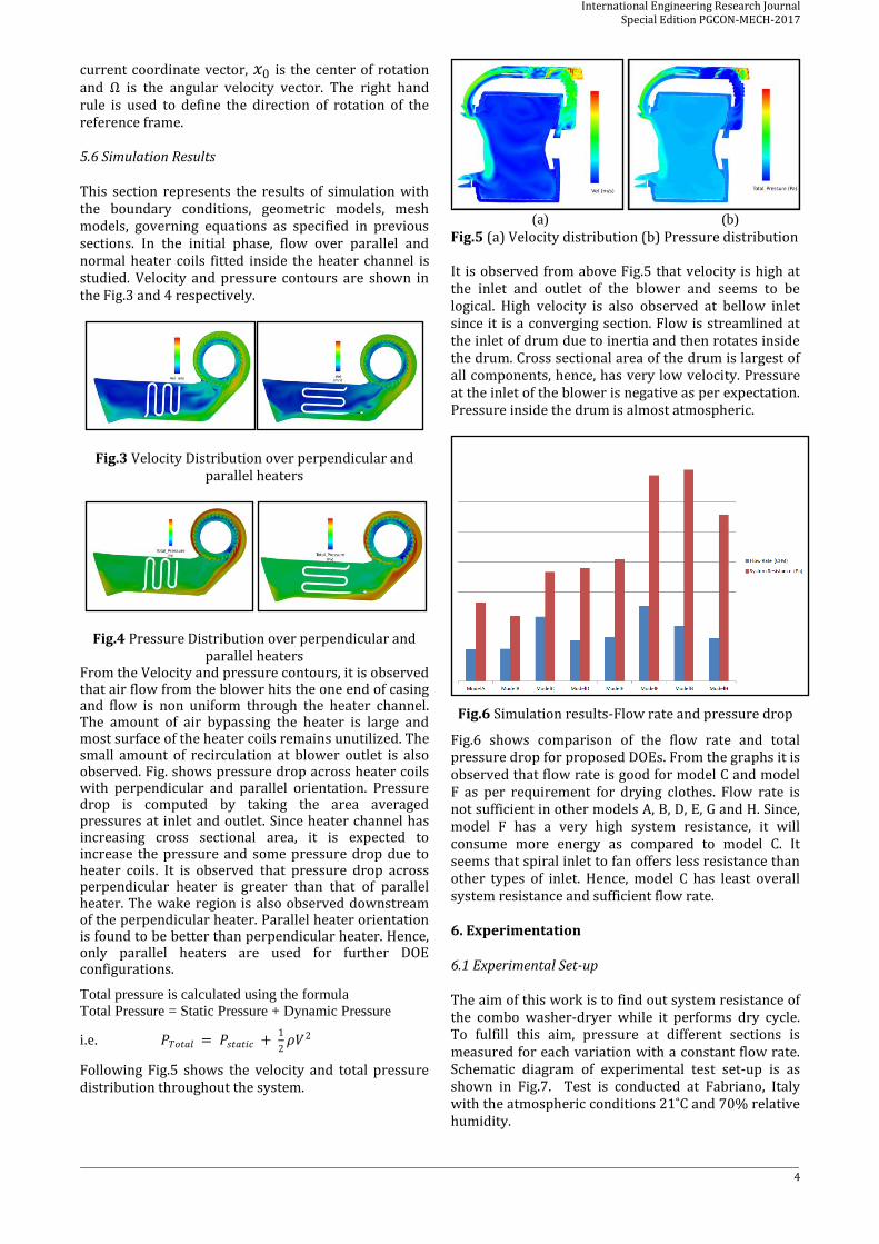
Fig.6 Simulation results-Flow rate and pressure drop
Fig.6 shows comparison of the flow rate and total pressure drop for proposed DOEs. From the graphs it is observed that flow rate is good for model C and model F as per requirement for drying clothes. Flow rate is not sufficient in other models A, B, D, E, G and H. Since, model F has a very high system resistance, it will consume more energy as compared to model C. It seems that spiral inlet to fan offers less resistance than other types of inlet. Hence, model C has least overall system resistance and sufficient flow rate. 6. Experimentation 6.1 Experimental Set-up The aim of this work is to find out system resistance of the combo washer-dryer while it performs dry cycle. To fulfill this aim, pressure at different sections is measured for each variation with a constant flow rate. Schematic diagram of experimental test set-up is as shown in Fig.7. Test is conducted at Fabriano, Italy with the atmospheric conditions 21˚C and 70% relative humidity.
International Engineering Research Journal Special Edition PGCON-MECH-2017
5
Fig.7 Schematic diagram of test set-up
Test set-up consists of a centrifugal blower attached to inlet of a wind tunnel. Wind tunnel has a diffuser at the inlet and an orifice meter at the mid-section. Orifice meter is used to measure flow rate. Pressures before and after the orifice plate are measured using precise pressure gauges.
𝑞𝑣 = 𝐶𝑑𝐴2 1
1 − (𝐴2 − 𝐴1)2
2(𝑃1 − 𝑃2)
𝜌
Where,
𝐶𝑑= Coefficient of discharge = 0.75;
𝐴2= Internal orifice area = 𝜋
4𝑑2 ;
𝐴1= Flow area before orifice = Width X Height;
𝑃1= Pressure before orifice plate;
𝑃2= Pressure after orifice plate;
𝜌 = Density of fluid (Air).
Air flows through the setup is shown by arrows. After wind tunnel, air enters the heater channel section and then passes through bellow, door glass drum, rear duct and finally released to the atmosphere. Pressure is measured across heater channel, bellow, drum, rear duct and pressure drop is calculated.
6.2 Experimentation Results
Results obtained from experiment are summarized in column chart as shown in Fig.8 Comparison of the DOEs reflects that Model C has sufficient flow rate and less resistance which is in good agreement with simulation results.
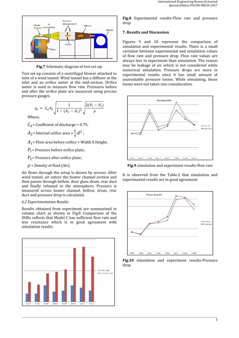
Fig.8 Experimental results-Flow rate and pressure drop 7. Results and Discussion Figures 9 and 10 represent the comparison of simulation and experimental results. There is a small variation between experimental and simulation values of flow rate and pressure drop. Flow rate values are always less in experiment than simulation. The reason may be leakage of air which is not considered while numerical simulation. Pressure drops are more in experimental results since it has small amount of unavoidable pressure losses. While simulating, those losses were not taken into consideration.
Fig.9 simulation and experiment results-flow rate
It is observed from the Table.2 that simulation and experimental results are in good agreement.
Fig.10 simulation and experiment results-Pressure drop

International Engineering Research Journal Special Edition PGCON-MECH-2017
6
Table.2 variations between simulation and experimental results
Model % Variation in flow rate
% variation in Pressure Drop
Model A 1.33 2.70
Model B 6.58 5.50
Model C 8.13 1.94
Model D 12.12 4.80
Model E 5.61 11.35
Model F 18.18 6.77
Model G 6.48 1.86
Model H 3.28 11.10
7. Conclusion
This work investigates the flow rate and system resistance of combo washer-dryer DOEs during dry cycle. The following important points emerge from the study.
1. Parallel heaters offer less resistance to flow as compared to perpendicular heater. Also flow over the parallel heater is streamlined and more area comes in contact with air which results in more heat transfer from heater to air and greater efficiency.
2. Spiral inlet to fan has streamlined flow and has minimum pressure drop.
3. Diffuser section at bellow inlet reduces the system resistance and air enters the drum at appropriate velocity which results in no bombardment on door glass profile.
From the above discussion, it is revealed that experimental and simulation results are consistent with each other hence, only numerical simulation can be used for further analysis with the same strategy which can save experimentation cost. Acknowledgment
Authors would like to thank the whirlpool corporation for their financial support and providing opportunity to access Acusolve, FluidNexus and Fieldview softwares. Furthermore, the authors would like to express their gratitude to lab technicians of testing lab in Fabriano, Italy for providing experimental results as per requirement of research. References [1] P.K. Bansal, J.E. Braun and E.A. Groll, “Improving energy
efficiency of conventional tumbler clothes drying systems”, International journal of energy research, Vol 25 (2001), pp. 1853-1864.
[2] Pradeep Bansal, Amar Mohabir, William Miller, “A novel method to determine air leakage in heat pump clothes dryers”,Energy, Elsevier, Vol 96 (2016), pp.1-7.
[3] J.E. Braun, P.K. Bansal and E.A. Groll, “Energy efficiency analysis of air cycle heat pump dryers”, International journal of refrigeration, Vol 25 (2002), pp.954-965.
[4] Pradeep Bansal, Karishma Sharma, Sumana Islam, “Thermal analysis of a new concept in a household
clothes tumble dryer”, Applied Energy, Elsevier, Vol 87 (2010), pp.1562-1571.
[5] Manuel R. Conde, “Energy conservation with tumbler drying in laundries”, Applied Thermal Engineering, Pergoman, Vol 17 (1997), pp.1163-1172.
[6] C. Junior, G. Chen, J. Koehler, “Modelling a new recuperative thermoelectric cycle for a tumble dryer”, International journal of heat and mass transfer, Elsevier, Vol 55 (2012), pp.1536-1543.
[7] Ferdinando Mancini, Siliva Minetto and Ezio Fornaseiri, “Thermodynamic analysis and Experimental investigation of a CO2 household heat pump dryer”, International journal of refrigeration, Elsevier, Vol 34 (2011), pp.851-858.
[8] Kamal Rezk and Jan Forsberg, “Geometry development of the internal duct system of a heat pump tumble dryer based on fluid mechanic parameters from a CFD software”, Applied Energy, Elsevier, Vol 88 (2011), pp.1596-1605.
[9] Lena Stawreberg, Jonas Berghel and Roger Renström, “Energy losses by air leakage in condensing tumble dryers”, Applied Thermal Engineering, Elsevier, Vol 37 (2012), pp.373-379.
[10] Lena Stawreberg and Lars Nilsson, “Potential energy savings made by using a specific control strategy when tumble drying small loads”, Applied Energy, Elsevier, Vol 102 (2013), pp.484-491.
[11] V. Yadav, C.G. Moon, “Modelling and experimentation for the fabric –drying process in domestic dryers”, Applied Energy, Elsevier, Vol 85 (2008), pp.404-419.