International Electronic Journal of Pure and Applied ...
24
International Electronic Journal of Pure and Applied Mathematics —————————————————————————————— Volume 4 No. 1 2012, 9-32 MHD FLOW IN POROUS MEDIA OVER A STRETCHING SURFACE IN ROTATING SYSTEM WITH HEAT AND MASS TRANSFER K. Giterere 1 § , M. Kinyanjui 2 , S.M. Uppal 3 1,2,3 P.O. Box 62000-00200, NAIROBI, KENYA Abstract: In this work, finite difference method is applied to study unsteady hydromagnetic boundary-layer flow and heat transfer of a Newtonian fluid due to a stretching sheet in a rotating system. The sheet is embedded in a uniform porous medium and is subjected to transverse magnetic field that cuts perpendicularly across the flow. The analytic solutions of the system of nonlinear partial differential equations are derived. The velocity, temperature, and concentration profiles are shown and the influence of non-dimensional parameters on the flow field is discussed in detail. The Reynolds number Re, Prandtl number Pr, Eckert Number Ec, Mag- netic parameter M, the Suction parameter wo, Joule heating parameter N, Radiation parameter R, Permeability constant K, Rotational parameter Ro, local temperature Grashof number Gr θ , the local mass Grashof number Gr c , Schmidt number Sc and Soret number Sr are investigated. The resulting velocity, temperature and concen- tration profiles are presented graphically.The skin-friction, rate of mass transfer and local wall heat flux are derived using the Least Sqaures Method and tabulated. Key Words: magnetohydrodynamics, natural convection, boundary layer, radia- tion, joule heating, coriolis force 1. Introduction In last few years there has been a great interest to investigate the boundary layer flows of viscous fluids due to a uniformly stretching sheet because of its technologi- cal applications in diverse areas such as metallurgical and polymer sheet extrusion from a die. A good amount of references on fluid flow through porous media in rotating systems can be found in the papers by Magyari and Keller (1999, 2000), Received: March 10, 2011 c 2012 Academic Publications, Ltd. § Correspondence author International Electronic Journal of Pure and Applied Mathematics – IEJPAM, Volume 4, No. 1 (2012)
Transcript of International Electronic Journal of Pure and Applied ...
International Electronic Journal of Pure and Applied Mathematics——————————————————————————————Volume 4 No. 1 2012, 9-32
MHD FLOW IN POROUS MEDIA OVER A STRETCHING
SURFACE IN ROTATING SYSTEM WITH
HEAT AND MASS TRANSFER
K. Giterere1 §, M. Kinyanjui2, S.M. Uppal3
1,2,3P.O. Box 62000-00200, NAIROBI, KENYA
Abstract: In this work, finite difference method is applied to study unsteadyhydromagnetic boundary-layer flow and heat transfer of a Newtonian fluid due to astretching sheet in a rotating system. The sheet is embedded in a uniform porousmedium and is subjected to transverse magnetic field that cuts perpendicularlyacross the flow. The analytic solutions of the system of nonlinear partial differentialequations are derived. The velocity, temperature, and concentration profiles areshown and the influence of non-dimensional parameters on the flow field is discussedin detail. The Reynolds number Re, Prandtl number Pr, Eckert Number Ec, Mag-netic parameter M, the Suction parameter wo, Joule heating parameter N, Radiationparameter R, Permeability constant K, Rotational parameter Ro, local temperatureGrashof number Grθ, the local mass Grashof number Grc, Schmidt number Sc andSoret number Sr are investigated. The resulting velocity, temperature and concen-tration profiles are presented graphically.The skin-friction, rate of mass transfer andlocal wall heat flux are derived using the Least Sqaures Method and tabulated.
Key Words: magnetohydrodynamics, natural convection, boundary layer, radia-tion, joule heating, coriolis force
1. Introduction
In last few years there has been a great interest to investigate the boundary layerflows of viscous fluids due to a uniformly stretching sheet because of its technologi-cal applications in diverse areas such as metallurgical and polymer sheet extrusionfrom a die. A good amount of references on fluid flow through porous media inrotating systems can be found in the papers by Magyari and Keller (1999, 2000),
Received: March 10, 2011 c© 2012 Academic Publications, Ltd.§Correspondence author
Intern
ationalElectronic
Journ
alofPure
and
Applied
Math
ematics–IE
JPAM
,Volume4,No.1(2
012)
10 K. Giterere, M. Kinyanjui, S.M. Uppal
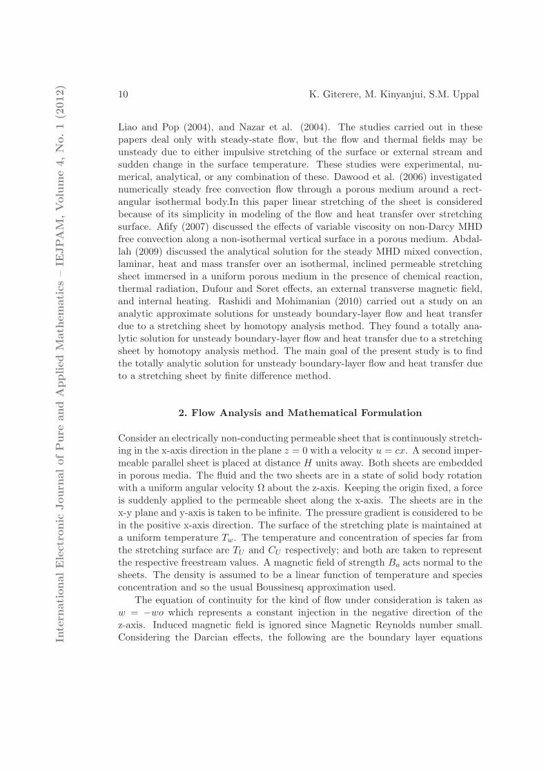
Liao and Pop (2004), and Nazar et al. (2004). The studies carried out in thesepapers deal only with steady-state flow, but the flow and thermal fields may beunsteady due to either impulsive stretching of the surface or external stream andsudden change in the surface temperature. These studies were experimental, nu-merical, analytical, or any combination of these. Dawood et al. (2006) investigatednumerically steady free convection flow through a porous medium around a rect-angular isothermal body.In this paper linear stretching of the sheet is consideredbecause of its simplicity in modeling of the flow and heat transfer over stretchingsurface. Afify (2007) discussed the effects of variable viscosity on non-Darcy MHDfree convection along a non-isothermal vertical surface in a porous medium. Abdal-lah (2009) discussed the analytical solution for the steady MHD mixed convection,laminar, heat and mass transfer over an isothermal, inclined permeable stretchingsheet immersed in a uniform porous medium in the presence of chemical reaction,thermal radiation, Dufour and Soret effects, an external transverse magnetic field,and internal heating. Rashidi and Mohimanian (2010) carried out a study on ananalytic approximate solutions for unsteady boundary-layer flow and heat transferdue to a stretching sheet by homotopy analysis method. They found a totally ana-lytic solution for unsteady boundary-layer flow and heat transfer due to a stretchingsheet by homotopy analysis method. The main goal of the present study is to findthe totally analytic solution for unsteady boundary-layer flow and heat transfer dueto a stretching sheet by finite difference method.
2. Flow Analysis and Mathematical Formulation
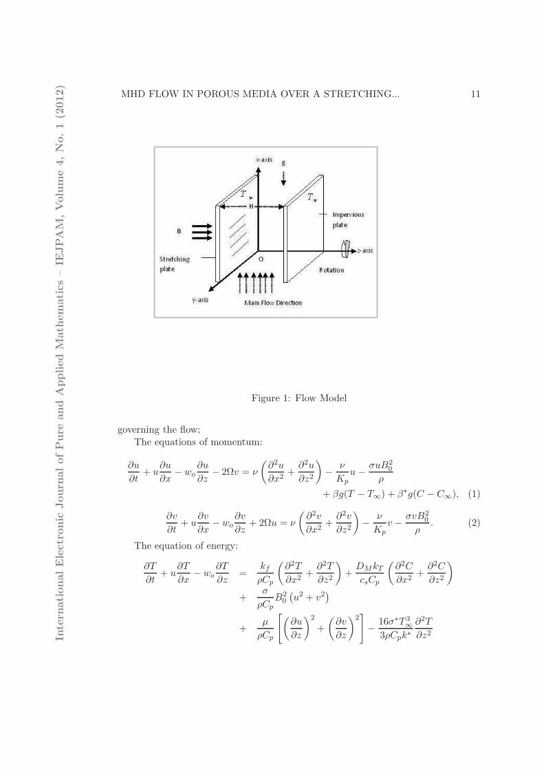
Consider an electrically non-conducting permeable sheet that is continuously stretch-ing in the x-axis direction in the plane z = 0 with a velocity u = cx. A second imper-meable parallel sheet is placed at distance H units away. Both sheets are embeddedin porous media. The fluid and the two sheets are in a state of solid body rotationwith a uniform angular velocity Ω about the z-axis. Keeping the origin fixed, a forceis suddenly applied to the permeable sheet along the x-axis. The sheets are in thex-y plane and y-axis is taken to be infinite. The pressure gradient is considered to bein the positive x-axis direction. The surface of the stretching plate is maintained ata uniform temperature Tw. The temperature and concentration of species far fromthe stretching surface are TU and CU respectively; and both are taken to representthe respective freestream values. A magnetic field of strength Bo acts normal to thesheets. The density is assumed to be a linear function of temperature and speciesconcentration and so the usual Boussinesq approximation used.
The equation of continuity for the kind of flow under consideration is taken asw = −wo which represents a constant injection in the negative direction of thez-axis. Induced magnetic field is ignored since Magnetic Reynolds number small.Considering the Darcian effects, the following are the boundary layer equationsIn
tern
ationalElectronic
Journ
alofPure
and
Applied
Math
ematics–IE
JPAM
,Volume4,No.1(2
012)
MHD FLOW IN POROUS MEDIA OVER A STRETCHING... 11
Figure 1: Flow Model
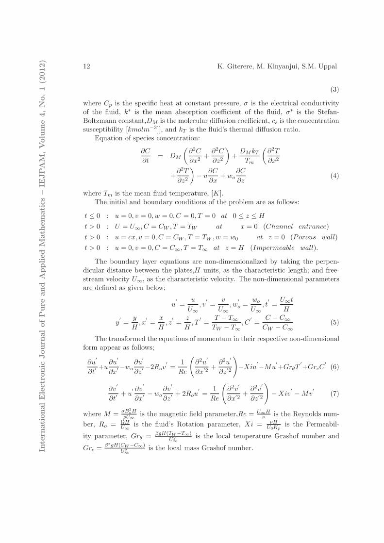
governing the flow;The equations of momentum:
∂u
∂t+ u
∂u
∂x− wo
∂u
∂z− 2Ωv = ν
(
∂2u
∂x2+
∂2u
∂z2
)
−ν
Kp
u−σuB2
0
ρ
+ βg(T − T∞) + β∗g(C − C∞), (1)
∂v
∂t+ u
∂v
∂x− wo
∂v
∂z+ 2Ωu = ν
(
∂2v
∂x2+
∂2v
∂z2
)
−ν
Kpv −
σvB20
ρ. (2)
The equation of energy:
∂T
∂t+ u
∂T
∂x− wo
∂T
∂z=
kfρCp
(
∂2T
∂x2+
∂2T
∂z2
)
+DMkTcsCp
(
∂2C
∂x2+
∂2C
∂z2
)
+σ
ρCp
B20
(
u2 + v2)
+µ
ρCp
[
(
∂u
∂z
)2
+
(
∂v
∂z
)2]
−16σ∗T 3
∞
3ρCpk∗∂2T
∂z2Intern
ationalElectronic
Journ
alofPure
and
Applied
Math
ematics–IE
JPAM
,Volume4,No.1(2
012)
12 K. Giterere, M. Kinyanjui, S.M. Uppal
(3)
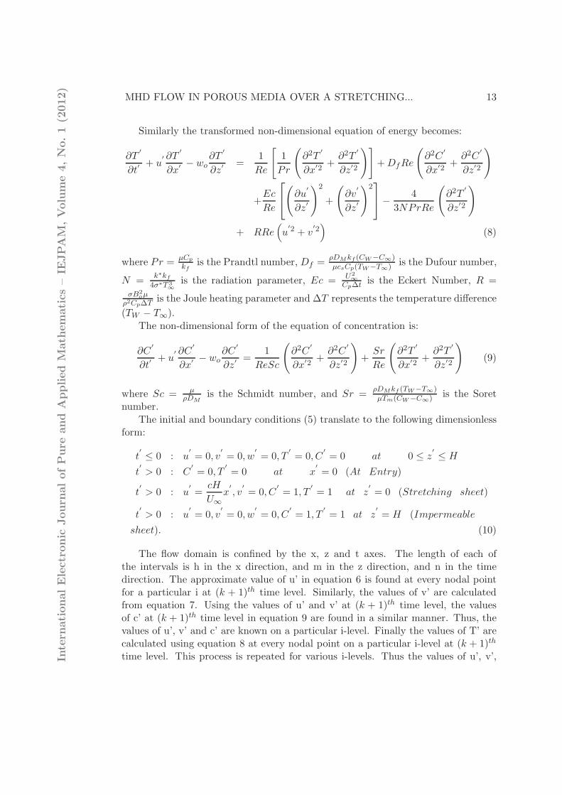
where Cp is the specific heat at constant pressure, σ is the electrical conductivityof the fluid, k∗ is the mean absorption coefficient of the fluid, σ∗ is the Stefan-Boltzmann constant,DM is the molecular diffusion coefficient, cs is the concentrationsusceptibility [kmolm−3]], and kT is the fluid’s thermal diffusion ratio.
Equation of species concentration:
∂C
∂t= DM
(
∂2C
∂x2+
∂2C
∂z2
)
+DMkTTm
(
∂2T
∂x2
+∂2T
∂z2
)
− u∂C
∂x+ wo
∂C
∂z(4)
where Tm is the mean fluid temperature, [K].The initial and boundary conditions of the problem are as follows:
t ≤ 0 : u = 0, v = 0, w = 0, C = 0, T = 0 at 0 ≤ z ≤ H
t > 0 : U = U∞, C = CW , T = TW at x = 0 (Channel entrance)
t > 0 : u = cx, v = 0, C = CW , T = TW , w = w0 at z = 0 (Porous wall)
t > 0 : u = 0, v = 0, C = C∞, T = T∞ at z = H (Impermeable wall).
The boundary layer equations are non-dimensionalized by taking the perpen-dicular distance between the plates,H units, as the characteristic length; and free-stream velocity U∞, as the characteristic velocity. The non-dimensional parametersare defined as given below;
u′
=u
U∞
, v′
=v
U∞
, w′
o =wo
U∞
, t′
=U∞t
H
y′
=y
H, x
′
=x
H, z
′
=z
H, T
′
=T − T∞
TW − T∞
, C′
=C − C∞
CW − C∞
(5)
The transformed the equations of momentum in their respective non-dimensionalform appear as follows;
∂u′
∂t′+u
∂u′
∂x′−wo
∂u′
∂z′−2Rov
′
=1
Re
(
∂2u′
∂x′2+
∂2u′
∂z′2
)
−Xiu′
−Mu′
+GrθT′
+GrcC′
(6)
∂v′
∂t′+ u
′ ∂v′
∂x′− wo
∂v′
∂z′+ 2Rou
′
=1
Re
(
∂2v′
∂x′2+
∂2v′
∂z′2
)
−Xiv′
−Mv′
(7)
where M = σB2oH
ρU∞
is the magnetic field parameter,Re = U∞Hν
is the Reynolds num-
ber, Ro = ΩHU∞
is the fluid’s Rotation parameter, Xi = νHU0Kp
is the Permeabil-
ity parameter, Grθ = βgH(TW−T∞)U2∞
is the local temperature Grashof number and
Grc =β∗gH(CW−C∞)
U2∞
is the local mass Grashof number.Intern
ationalElectronic
Journ
alofPure
and
Applied
Math
ematics–IE
JPAM
,Volume4,No.1(2
012)
MHD FLOW IN POROUS MEDIA OVER A STRETCHING... 13
Similarly the transformed non-dimensional equation of energy becomes:
∂T′
∂t′+ u
′ ∂T′
∂x′− wo
∂T′
∂z′=
1
Re
[
1
Pr
(
∂2T′
∂x′2+
∂2T′
∂z′2
)]
+DfRe
(
∂2C′
∂x′2+
∂2C′
∂z′2
)
+Ec
Re
(
∂u′
∂z′
)2
+
(
∂v′
∂z′
)2
−4
3NPrRe
(
∂2T′
∂z′2
)
+ RRe(
u′2 + v
′2)
(8)
where Pr =µCp
kfis the Prandtl number, Df =
ρDMkf (CW−C∞)µcsCp(TW−T∞) is the Dufour number,
N =k∗kf
4σ∗T 3∞
is the radiation parameter, Ec = U2∞
Cp∆tis the Eckert Number, R =
σB2oµ
ρ2Cp∆Tis the Joule heating parameter and ∆T represents the temperature difference
(TW − T∞).
The non-dimensional form of the equation of concentration is:
∂C′
∂t′+ u
′ ∂C′
∂x′− wo
∂C′
∂z′=
1
ReSc
(
∂2C′
∂x′2+
∂2C′
∂z′2
)
+Sr
Re
(
∂2T′
∂x′2+
∂2T′
∂z′2
)
(9)
where Sc = µρDM
is the Schmidt number, and Sr =ρDMkf (TW−T∞)µTm(CW−C∞) is the Soret
number.
The initial and boundary conditions (5) translate to the following dimensionlessform:
t′
≤ 0 : u′
= 0, v′
= 0, w′
= 0, T′
= 0, C′
= 0 at 0 ≤ z′
≤ H
t′
> 0 : C′
= 0, T′
= 0 at x′
= 0 (At Entry)
t′
> 0 : u′
=cH
U∞
x′
, v′
= 0, C′
= 1, T′
= 1 at z′
= 0 (Stretching sheet)
t′
> 0 : u′
= 0, v′
= 0, w′
= 0, C′
= 1, T′
= 1 at z′
= H (Impermeable
sheet). (10)
The flow domain is confined by the x, z and t axes. The length of each ofthe intervals is h in the x direction, and m in the z direction, and n in the timedirection. The approximate value of u’ in equation 6 is found at every nodal pointfor a particular i at (k + 1)th time level. Similarly, the values of v’ are calculatedfrom equation 7. Using the values of u’ and v’ at (k + 1)th time level, the valuesof c’ at (k + 1)th time level in equation 9 are found in a similar manner. Thus, thevalues of u’, v’ and c’ are known on a particular i-level. Finally the values of T’ arecalculated using equation 8 at every nodal point on a particular i-level at (k + 1)th
time level. This process is repeated for various i-levels. Thus the values of u’, v’,Intern
ationalElectronic
Journ
alofPure
and
Applied
Math
ematics–IE
JPAM
,Volume4,No.1(2
012)

14 K. Giterere, M. Kinyanjui, S.M. Uppal
c’ and T’ are determined at all grid points in the rectangular region at (k + 1)th
time level. The derivatives are approximated with the forward-time backward-space(FTBS) difference scheme. The expressions for u’, u
′
x and u′
xx are averaged for timesk and (k+1). This approximation is repeated for v’ and c’ and T’. For simplicity u’,v’, c’ and T’ are replaced by U, V, C and T and the primes are removed. The finitedifference equations corresponding to equations 6 to 9 together with the initial andboundary conditions 10 are given below;
Equations of momentum:
Uk+1i,j = [Uk
i,j −∆t
2∆xUki,j(−Uk+1
i−1,j + Uki,j − Uk
i−1,j) +wo∆t
2∆z(−Uk+1
i,j−1 + Uki,j − Uk
i,j−1)
+Ro∆t(V k+1i,j + V k
i,j) +∆t
2Re(∆x)2(Uk+1
i+1,j + Uk+1i−1,j + Uk
i+1,j − 2Uki,j + Uk
i−1,j)
+∆t
2Re(∆z)2(Uk+1
i,j+1 + Uk+1i,j−1 + Uk
i,j+1 − 2 ∗ Uki,j + Uk
i,j−1)−Xi∆T
2Uki,j
−M∆t
2Uki,j +
∆tGrθ2
(T k+1i,j + T k
i,j) +∆tGrc
2(Ck+1
i,j + Cki,j)]/[1 + Uk
i,j
∆t
2∆x
−wo∆t
2∆z+
∆t
Re(∆x)2+
∆t
Re ∗ (∆z)2+
∆tXi
2+
1
2M∆t] (11)
V k+1i,j = [V k
i,j −∆t
2∆xUki,j(−V k+1
i−1,j + V ki,j − V k
i−1,j) +wo∆t
2∆z(−V k+1
i,j−1 + V ki,j − V k
i,j−1)
+Ro∆t(Uk+1i,j + Uk
i,j) +∆t
2Re(∆x)2(V k+1
i+1,j + V k+1i−1,j + V k
i+1,j − 2V ki,j + V k
i−1,j)
+∆t
2Re(∆z)2(V k+1
i,j+1 + V k+1i,j−1 + V k
i,j+1 − 2V ki,j + V k
i,j−1)−Xi∆T
2V ki,j
−M∆t
2V ki,j]/[1 + Uk
i,j
∆t
2∆x−
wo∆t
2∆z+
∆t
Re(∆x)2+
∆t
Re(∆z)2
+Xi∆T
2+
1
2M∆tT ] (12)
Equation of concentration:
Ck+1i,j = [Ck
i,j −∆t
2∆xUki,j(−Ck+1
i−1,j + Cki,j − Ck
i−1,j) +wo∆t
2∆z(−Ck+1
i,j−1 + Cki,j − Ck
i,j−1)
+∆t
2ScRe(∆x)2(Ck+1
i+1,j + Ck+1i−1,j + Ck
i+1,j − 2Cki,j + Ck
i−1,j)
+∆t
2ScRe(∆z)2(Ck+1
i,j+1 + Ck+1i,j−1 + Ck
i,j+1 − 2Cki,j + Ck
i,j−1)
+Sr∆T
2Re(∆x)2(T k+1
i+1,j − 2T k+1i,j + T k+1
i−1,j
+T ki+1,j − 2T k
i,j + T ki−1,j) +
Sr∆T
2Re(∆z)2(T k+1
i,j+1 − 2T k+1i,jIn
tern
ationalElectronic
Journ
alofPure
and
Applied
Math
ematics–IE
JPAM
,Volume4,No.1(2
012)
MHD FLOW IN POROUS MEDIA OVER A STRETCHING... 15
+T k+1i,j−1 + T k
i,j+1 − 2T ki,j + T k
i,j−1)]/[1 +∆t
2∆xUki,j
−wo∆t
2∆z+
∆t
ReSc(∆x)2+
∆t
ReSc(∆z)2] (13)
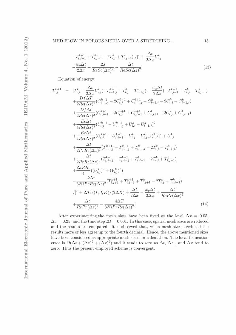
Equation of energy:
T k+1i,j = [T k
i,j −∆t
2∆xUki,j(−T k+1
i−1,j + T ki,j − T k
i−1,j) +wo∆t
2∆z(−T k+1
i,j−1 + T ki,j − T k
i,j−1)
+Df∆T
2Re(∆x)2(Ck+1
i+1,j − 2Ck+1i,j + Ck+1
i−1,j + Cki+1,j − 2Ck
i,j + Cki−1,j)
+Df∆t
2Re(∆z)2(Ck+1
i,j+1 − 2Ck+1i,j + Ck+1
i,j−1 + Cki,j+1 − 2Ck
i,j + Cki,j−1)
+Ec∆t
4Re(∆x)2(Uk+1
i,j − Uk+1i−1,j + Uk
i,j − Uki−1,j)
2
+Ec∆t
4Re(∆z)2(Uk+1
i,j − Uk+1i,j−1 + Uk
i,j − Uki,j−1)
2]/[1 + Uki,j
+∆t
2PrRe(∆x)2(T k+1
i+1,j + T k+1i−1,j + T k
i+1,j − 2T ki,j + T k
i−1,j)
+∆t
2PrRe(∆z)2(T k+1
i,j+1 + T k+1i,j−1 + T k
i,j+1 − 2T ki,j + T k
i,j−1)
+∆tRRe
4((Uk
i,j)2 + (V k
i,j)2)
−2∆t
3NiPrRe(∆z)2(T k+1
i,j+1 + T k+1i,j−1 + T k
i,j+1 − 2T ki,j + T k
i,j−1)
/[1 + ∆TU(I, J,K)/(2∆X) +∆t
2∆x−
wo∆t
2∆z+
∆t
RePr(∆x)2
+∆t
RePr(∆z)2−
4∆T
3NiPrRe(∆z)2] (14)
After experimenting,the mesh sizes have been fixed at the level ∆x = 0.05,∆z = 0.25, and the time step ∆t = 0.001. In this case, spatial mesh sizes are reducedand the results are compared. It is observed that, when mesh size is reduced theresults more or less agree up to the fourth decimal. Hence, the above mentioned sizeshave been considered as appropriate mesh sizes for calculation. The local truncationerror is O(∆t + (∆z)2 + (∆x)2) and it tends to zero as ∆t, ∆z , and ∆x tend tozero. Thus the present employed scheme is convergent.
Intern
ationalElectronic
Journ
alofPure
and
Applied
Math
ematics–IE
JPAM
,Volume4,No.1(2
012)
16 K. Giterere, M. Kinyanjui, S.M. Uppal
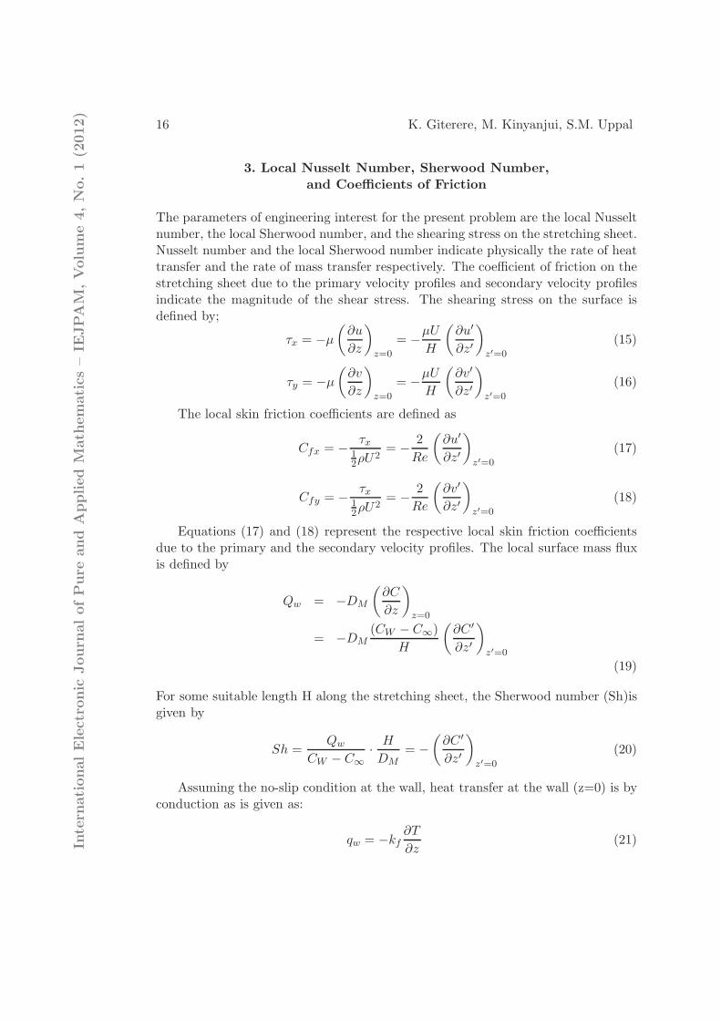
3. Local Nusselt Number, Sherwood Number,
and Coefficients of Friction
The parameters of engineering interest for the present problem are the local Nusseltnumber, the local Sherwood number, and the shearing stress on the stretching sheet.Nusselt number and the local Sherwood number indicate physically the rate of heattransfer and the rate of mass transfer respectively. The coefficient of friction on thestretching sheet due to the primary velocity profiles and secondary velocity profilesindicate the magnitude of the shear stress. The shearing stress on the surface isdefined by;
τx = −µ
(
∂u
∂z
)
z=0
= −µU
H
(
∂u′
∂z′
)
z′=0
(15)
τy = −µ
(
∂v
∂z
)
z=0
= −µU
H
(
∂v′
∂z′
)
z′=0
(16)
The local skin friction coefficients are defined as
Cfx = −τx
12ρU
2= −
2
Re
(
∂u′
∂z′
)
z′=0
(17)
Cfy = −τx
12ρU
2= −
2
Re
(
∂v′
∂z′
)
z′=0
(18)
Equations (17) and (18) represent the respective local skin friction coefficientsdue to the primary and the secondary velocity profiles. The local surface mass fluxis defined by
Qw = −DM
(
∂C
∂z
)
z=0
= −DM(CW − C∞)
H
(
∂C ′
∂z′
)
z′=0
(19)
For some suitable length H along the stretching sheet, the Sherwood number (Sh)isgiven by
Sh =Qw
CW − C∞
·H
DM
= −
(
∂C ′
∂z′
)
z′=0
(20)
Assuming the no-slip condition at the wall, heat transfer at the wall (z=0) is byconduction as is given as:
qw = −kf∂T
∂z(21)In
tern
ationalElectronic
Journ
alofPure
and
Applied
Math
ematics–IE
JPAM
,Volume4,No.1(2
012)
MHD FLOW IN POROUS MEDIA OVER A STRETCHING... 17
where kf is the thermal conductivity of the saturated porous medium. For somesuitable length H along the stretching sheet, the local Nusselt number (Nu) is givenas
Nu =qw
TW − T∞
·H
kf
=
(
∂T ′
∂z′
)
z′=0
(22)
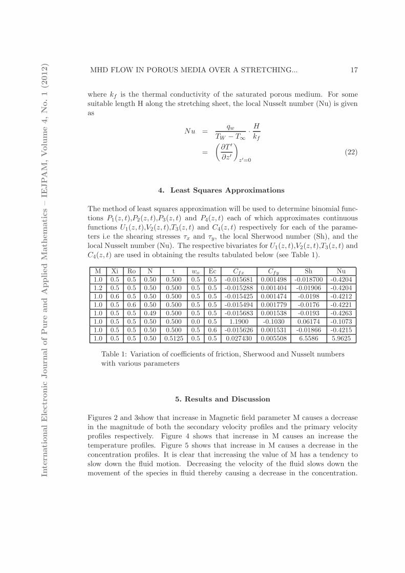
4. Least Squares Approximations
The method of least squares approximation will be used to determine binomial func-tions P1(z, t),P2(z, t),P3(z, t) and P4(z, t) each of which approximates continuousfunctions U1(z, t),V2(z, t),T3(z, t) and C4(z, t) respectively for each of the parame-ters i.e the shearing stresses τx and τy, the local Sherwood number (Sh), and thelocal Nusselt number (Nu). The respective bivariates for U1(z, t),V2(z, t),T3(z, t) andC4(z, t) are used in obtaining the results tabulated below (see Table 1).
M Xi Ro N t wo Ec Cfx Cfy Sh Nu1.0 0.5 0.5 0.50 0.500 0.5 0.5 -0.015681 0.001498 -0.018700 -0.42041.2 0.5 0.5 0.50 0.500 0.5 0.5 -0.015288 0.001404 -0.01906 -0.42041.0 0.6 0.5 0.50 0.500 0.5 0.5 -0.015425 0.001474 -0.0198 -0.42121.0 0.5 0.6 0.50 0.500 0.5 0.5 -0.015494 0.001779 -0.0176 -0.42211.0 0.5 0.5 0.49 0.500 0.5 0.5 -0.015683 0.001538 -0.0193 -0.42631.0 0.5 0.5 0.50 0.500 0.0 0.5 1.1900 -0.1030 0.06174 -0.10731.0 0.5 0.5 0.50 0.500 0.5 0.6 -0.015626 0.001531 -0.01866 -0.42151.0 0.5 0.5 0.50 0.5125 0.5 0.5 0.027430 0.005508 6.5586 5.9625
Table 1: Variation of coefficients of friction, Sherwood and Nusselt numberswith various parameters
5. Results and Discussion
Figures 2 and 3show that increase in Magnetic field parameter M causes a decreasein the magnitude of both the secondary velocity profiles and the primary velocityprofiles respectively. Figure 4 shows that increase in M causes an increase thetemperature profiles. Figure 5 shows that increase in M causes a decrease in theconcentration profiles. It is clear that increasing the value of M has a tendency toslow down the fluid motion. Decreasing the velocity of the fluid slows down themovement of the species in fluid thereby causing a decrease in the concentration.In
tern
ationalElectronic
Journ
alofPure
and
Applied
Math
ematics–IE
JPAM
,Volume4,No.1(2
012)

18 K. Giterere, M. Kinyanjui, S.M. Uppal
Figure 2: Variation of secondary ve-locity profiles with M.
Figure 3: Variation of primary veloc-ity profiles with M.
Application of a transverse magnetic field to an electrically conducting fluid gives arise to a resistive type force called the Lorentz force. This force has the tendencyto slow down the motion of the fluid in the boundary layer and to increase itstemperature and concentration. The magnetic field can be employed to control theflow and heat transfer characteristics of fluid in motion. The temperature profilesincrease with increasing M. The increasing frictional drag due to the Lorentz forceis responsible for increasing the thermal boundary layer thickness.
Figure 4: Variation of concentrationprofiles with M.
Figure 5: Variation of temperatureprofiles with M.
From Figure 6 increase in Sr causes a slight decrease in the primary velocityprofiles. From Figure 7 increase in Sr causes a slight decrease in the values ofthe secondary velocity profiles. From Figure 8 increase in Sr causes a significantdecrease in the concentration profiles. Soret number (Sr) defines the effect of thetemperature gradients inducing significant mass diffusion effects. From Figure 9In
tern
ationalElectronic
Journ
alofPure
and
Applied
Math
ematics–IE
JPAM
,Volume4,No.1(2
012)
MHD FLOW IN POROUS MEDIA OVER A STRETCHING... 19
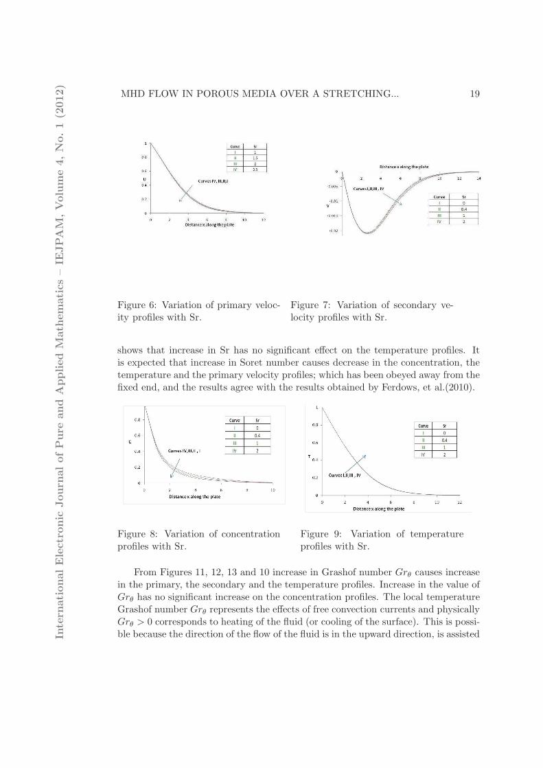
Figure 6: Variation of primary veloc-ity profiles with Sr.
Figure 7: Variation of secondary ve-locity profiles with Sr.
shows that increase in Sr has no significant effect on the temperature profiles. Itis expected that increase in Soret number causes decrease in the concentration, thetemperature and the primary velocity profiles; which has been obeyed away from thefixed end, and the results agree with the results obtained by Ferdows, et al.(2010).
Figure 8: Variation of concentrationprofiles with Sr.
Figure 9: Variation of temperatureprofiles with Sr.
From Figures 11, 12, 13 and 10 increase in Grashof number Grθ causes increasein the primary, the secondary and the temperature profiles. Increase in the value ofGrθ has no significant increase on the concentration profiles. The local temperatureGrashof number Grθ represents the effects of free convection currents and physicallyGrθ > 0 corresponds to heating of the fluid (or cooling of the surface). This is possi-ble because the direction of the flow of the fluid is in the upward direction, is assistedIn
tern
ationalElectronic
Journ
alofPure
and
Applied
Math
ematics–IE
JPAM
,Volume4,No.1(2
012)

20 K. Giterere, M. Kinyanjui, S.M. Uppal
Figure 10: Variation of primary veloc-ity profiles with Xi, Grθ and Grc.
Figure 11: Variation of secondary ve-locity profiles with Xi, Grθ and Grc.
by the free convection currents and hence the velocity increases. As expected, in-crease in the velocity profiles is partly due to the enhancement of thermal buoyancyforce. The species concentration keeps on decreasing and finally approaches zerowith increasing distance away from the fixed end of the stretching sheet. Free con-vection currents bring in more species near the surface above the stretching sheetand hence the observed increase in the species concentration; though such increasein the concentration is not very significant. Increase in Grθ causes the secondarycirculation currents to arise due to the presence of the temperature gradient.
Figure 11 shows that increase in modified Grashof number Grc causes increase inthe secondary velocity profiles. Figure 10 shows that increase in Grashof numberGrccauses an increase in the primary velocity profiles. Figure 12 shows that increasein the modified Grashof number Grc causes increase in the temperature profiles.Physically, it means that thermal boundary layer thickness decreases with increasein Grc, and hence the observed increase in the temperature profiles. Figure 13 showsthat increase in the modified Grashof number Grc causes an insignificant increasein the concentration profiles. The modified Grashof number Grc defines the ratioof the species buoyancy force to the viscous hydrodynamic force. As expected, thefluid velocity increases due to increase in the species buoyancy force. Increase inspecies buoyancy force results in increase in species concentration since this resultsin increase in solutal transportation towards the stretching surface.
Figure 11 shows that increase in Xi causes an increase in the secondary velocityprofiles. Figure 10 shows that increase in Xi causes decrease in the primary velocityprofiles. Figure 12 shows that increase in Xi causes decrease in the temperatureprofiles. Figure 13 shows that increase in Xi causes an insignificant decrease inthe concentration profiles. The permeability parameter Xi is inversely proportionalto the actual permeability Kp of the porous medium. Increase in Xi leads to en-In
tern
ationalElectronic
Journ
alofPure
and
Applied
Math
ematics–IE
JPAM
,Volume4,No.1(2
012)

MHD FLOW IN POROUS MEDIA OVER A STRETCHING... 21
Figure 12: Variation of temperatureprofiles with Xi, Grθ and Grc.
Figure 13: Variation of concentrationprofiles with Xi, Grθ and Grc.
hanced deceleration of the flow and hence the velocity decreases. (It is worth tonote that increase in Xi means a decrease in the magnitude of the value of veloc-ity profiles.) An increase in Xi will therefore increase the resistance of the porousmedium (as the permeability physically becomes less with increasing Xi ) whichwill tend to decelerate the flow and reduce the magnitudes of both the primary andthe secondary velocities. Thus velocity of the fluid can be controlled by introduc-ing a porous medium in a rotating system. Increase in Xi will reduce the rate ofspecies transportation within the medium, hence the observed insignificant decreasein the concentration profile. The velocity boundary layer thickness rather than thetemperature boundary layer seems to determine the temperature of the fluid. Thismeans increase in velocity translates to the fluid having less time to absorb moreheat, hence observed decrease in the temperature profiles.
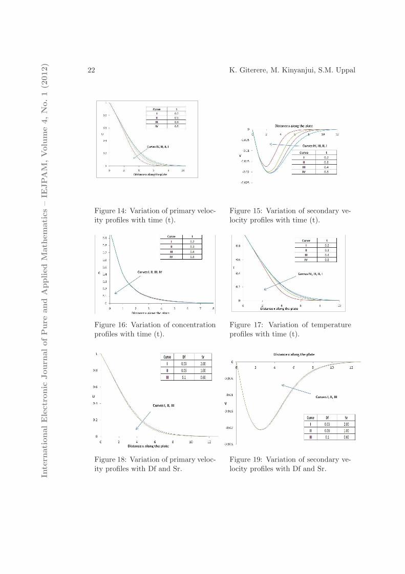
Figure 14 shows that increase in time (t) causes an increase in the primaryvelocity profiles. Figure 15 shows that increase in time (t) causes an increase inthe secondary velocity profiles. Figure 16 shows that increase in time (t) causesan insignificant decrease in the concentration profiles. It means the concentrationboundary layer slightly decreases with time. Figure 17 shows that increase in time(t) causes increase in the temperature profiles. Physically, it means that thermalboundary layer thickness increases with increase in time t. This is expected sincethe fluid absorbs heat from the stretching surface as transient time t increases. Itcan be seen from these figures that, as t increases the distribution of the velocities,the concentration and the temperature change with their position x along the sheet.
Figure 18 shows that increase in the Dufour number (Df) has a minor decreasingeffect in the primary velocity profiles. The values of Df and Sr are selected such thattheir product is a constant. Figure 19 shows that increase in Df causes a slightincrease in the secondary velocity profiles. Figure 20 shows that increase in DfIn
tern
ationalElectronic
Journ
alofPure
and
Applied
Math
ematics–IE
JPAM
,Volume4,No.1(2
012)
22 K. Giterere, M. Kinyanjui, S.M. Uppal
Figure 14: Variation of primary veloc-ity profiles with time (t).
Figure 15: Variation of secondary ve-locity profiles with time (t).
Figure 16: Variation of concentrationprofiles with time (t).
Figure 17: Variation of temperatureprofiles with time (t).
Figure 18: Variation of primary veloc-ity profiles with Df and Sr.
Figure 19: Variation of secondary ve-locity profiles with Df and Sr.
Intern
ationalElectronic
Journ
alofPure
and
Applied
Math
ematics–IE
JPAM
,Volume4,No.1(2
012)

MHD FLOW IN POROUS MEDIA OVER A STRETCHING... 23
causes a significant decrease in the concentration profiles. Figure 21 shows thatincrease in Df causes a decrease in the temperature profiles. The Dufour number Dfsignifies the contribution of the concentration gradients to the thermal energy flux inthe flow. It can be clearly seen from this figure that diffusion thermal effects greatlyaffect the fluid temperature. Since a decrease in the Dufour number translates to anincrease the velocity profiles, the temperature of the fluid is expected to rise. Figure18 shows that a decrease in the Soret number (Sr) causes a decrease in the primaryvelocity profiles. Figure 19 shows that decrease in Sr causes a slight increase in thesecondary velocity profiles. Figure 20 shows that increase in Sr causes a significantincrease in the concentration profiles. Figure 21 shows that increase in Sr causes aincrease in the temperature profiles. The Soret number Sr defines the effect of thetemperature gradients inducing significant mass diffusion effects. Thus increase inSr accompanied by an increase in the temperature as well as in the concentrationprofiles is an expected result.
Figure 20: Variation of concentrationprofiles with Df and Sr.
Figure 21: Variation of temperatureprofiles with Df and Sr.
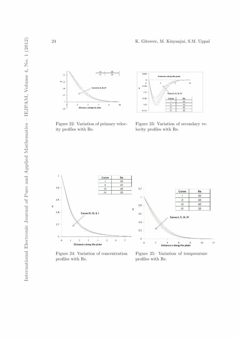
Figure 22 and 23 and show that increase in Reynold’s number Re leads to anincrease in the magnitude of the values of both the secondary and the primaryvelocity profiles. The Reynolds number is the ratio of the inertial to viscosity forces.Increase in Re is results in a larger inertia force that in turn translates to a highervelocity. Figure 24 and 25 show that increase in Re causes a decrease in both thetemperature and the concentration profiles. A higher value of Re increases velocityof the fluid. A higher velocity of the fluid takes more species away from near thesurface of the stretching sheet and also ensures the fluid absorbs less heat. Thisexplains why there both the temperature and the concentration profiles decrease.
Figures 26, 27 and 29 show that increase in Radiation parameter N leads to anincrease in the primary, the secondary and the temperature profiles. Figures and 28show that increase in N causes a minor increase of the the concentration profiles.So, radiation can be used to control the velocity and the thermal boundary layersin porous media quite effectively. So lowering the value of N decreases both flowvelocities as well as the temperature of the fluid. It is also worth noting that theIn
tern
ationalElectronic
Journ
alofPure
and
Applied
Math
ematics–IE
JPAM
,Volume4,No.1(2
012)
24 K. Giterere, M. Kinyanjui, S.M. Uppal
Figure 22: Variation of primary veloc-ity profiles with Re.
Figure 23: Variation of secondary ve-locity profiles with Re.
Figure 24: Variation of concentrationprofiles with Re.
Figure 25: Variation of temperatureprofiles with Re.
Intern
ationalElectronic
Journ
alofPure
and
Applied
Math
ematics–IE
JPAM
,Volume4,No.1(2
012)

MHD FLOW IN POROUS MEDIA OVER A STRETCHING... 25
rate of boundary layer growth for both the temperature and velocities is higher nearthe fixed end of stretching sheet.
Figure 26: Variation of primary veloc-ity profiles with N and Ec.
Figure 27: Variation of secondary ve-locity profiles with N and Ec.
Figure 28: Variation of concentrationprofiles with N and Ec.
Figure 29: Variation of temperatureprofiles with N and Ec.
Figures 26 and 29 show that increase in Eckert number (Ec) causes a increase inboth the primary velocity and the temperature profiles. Thus an increased cooling(positive Grashof number) of the sheet and increasing Eckert number boost velocityprofile and the temperature of the flow in the porous medium. The Eckert number Ecexpresses the relationship between the kinetic energy in the flow and the enthalpy. Itembodies the conversion of kinetic energy into internal energy by work done againstthe viscous fluid stresses. The positive Eckert number implies cooling of the sheeti.e., loss of heat from the sheet to the fluid. Hence, greater viscous dissipative heatcauses a rise in the temperature as well as the velocity. From Figures 27 and 28,increase in Ec causes an increase in the secondary velocity profiles but a minor changein the concentration profiles. So, varying the Eckert number can be used to controlthe velocity and the thermal boundary layers in porous media quite effectively.
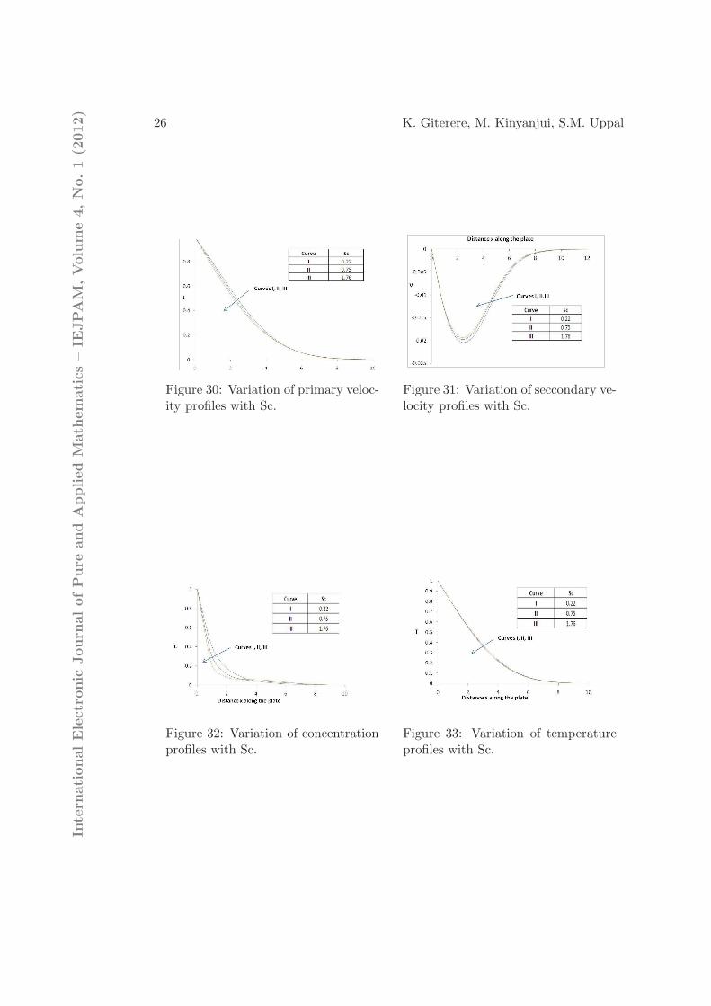
Figures 30 and 32 show that increase in Schmidt number(Sc) causes decreaseIntern
ationalElectronic
Journ
alofPure
and
Applied
Math
ematics–IE
JPAM
,Volume4,No.1(2
012)
26 K. Giterere, M. Kinyanjui, S.M. Uppal
Figure 30: Variation of primary veloc-ity profiles with Sc.
Figure 31: Variation of seccondary ve-locity profiles with Sc.
Figure 32: Variation of concentrationprofiles with Sc.
Figure 33: Variation of temperatureprofiles with Sc.
Intern
ationalElectronic
Journ
alofPure
and
Applied
Math
ematics–IE
JPAM
,Volume4,No.1(2
012)
MHD FLOW IN POROUS MEDIA OVER A STRETCHING... 27
in the primary velocity profiles. Increase in Schmidt number(Sc) causes decrease inthe concentration profiles near the fixed end of the stretching sheet; however thereis a cross-over of the concentration profiles at around x=4. Figure 31 shows thatan increase in Sc leads to an increase in the secondary velocity profiles. Figure 33shows that increase in Sc leads to some insignificant decrease in the temperatureprofiles. Realistic value of 0.62 is chosen for water vapor at temperature 25 C andone atmospheric pressure. An increase in Sc leads to thinning of the velocity and theconcentration boundary layers, respectively (Abo-Eldahab,2005). Thus stretchingleads to the thinning of both the velocity and the concentration boundary layersnear the fixed end of the stretching sheet. A large value of Sc implies the presenceof a heavier fluid and this would lead to a lower velocity of the fluid.
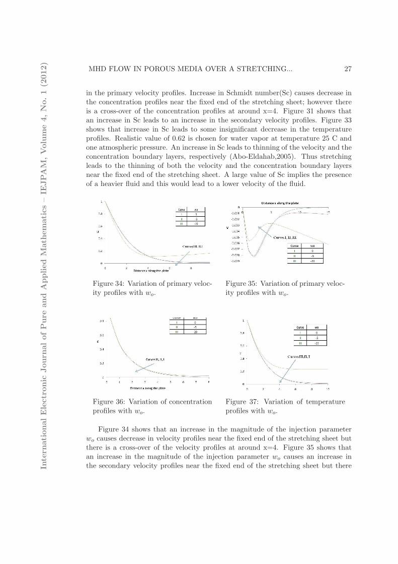
Figure 34: Variation of primary veloc-ity profiles with wo.
Figure 35: Variation of primary veloc-ity profiles with wo.
Figure 36: Variation of concentrationprofiles with wo.
Figure 37: Variation of temperatureprofiles with wo.
Figure 34 shows that an increase in the magnitude of the injection parameterwo causes decrease in velocity profiles near the fixed end of the stretching sheet butthere is a cross-over of the velocity profiles at around x=4. Figure 35 shows thatan increase in the magnitude of the injection parameter wo causes an increase inthe secondary velocity profiles near the fixed end of the stretching sheet but thereIn
tern
ationalElectronic
Journ
alofPure
and
Applied
Math
ematics–IE
JPAM
,Volume4,No.1(2
012)
28 K. Giterere, M. Kinyanjui, S.M. Uppal
is a cross-over of the velocity profiles at around x=5. Figure 36 shows that anincrease in the magnitude of the injection parameter wo causes a minor increase inthe concentration profiles. Figure 37 shows that an increase in the magnitude ofthe injection parameter wo causes a decrease in the temperature profiles. Injectingfluid particles through the permeable sheet increases both the primary velocity andthe thermal boundary layers. Introducing injection can be used to destabilize thevelocity and the temperature boundary layers. This indicates the usual fact thatblowing destabilizes both the primary velocity and the temperature the boundarylayers growth.
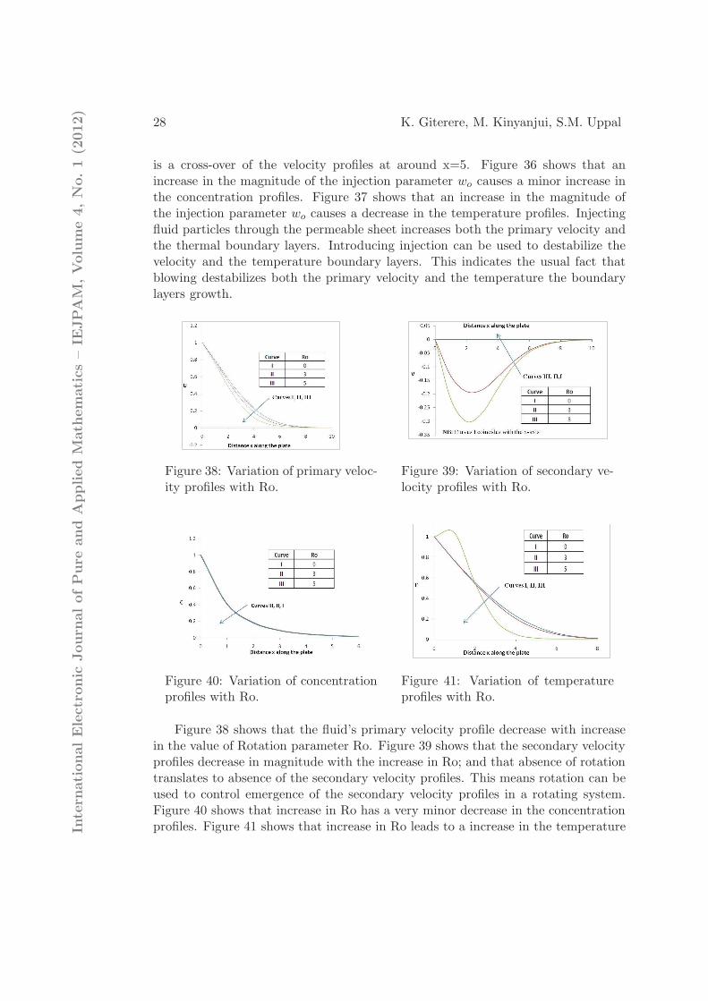
Figure 38: Variation of primary veloc-ity profiles with Ro.
Figure 39: Variation of secondary ve-locity profiles with Ro.
Figure 40: Variation of concentrationprofiles with Ro.
Figure 41: Variation of temperatureprofiles with Ro.
Figure 38 shows that the fluid’s primary velocity profile decrease with increasein the value of Rotation parameter Ro. Figure 39 shows that the secondary velocityprofiles decrease in magnitude with the increase in Ro; and that absence of rotationtranslates to absence of the secondary velocity profiles. This means rotation can beused to control emergence of the secondary velocity profiles in a rotating system.Figure 40 shows that increase in Ro has a very minor decrease in the concentrationprofiles. Figure 41 shows that increase in Ro leads to a increase in the temperatureIn
tern
ationalElectronic
Journ
alofPure
and
Applied
Math
ematics–IE
JPAM
,Volume4,No.1(2
012)
MHD FLOW IN POROUS MEDIA OVER A STRETCHING... 29
profiles near the fixed end of the stretching sheet but to a decrease in the temperatureprofiles away from the fixed end. There is a cross-over in the temperature profiles ataround x=2. An increase in Ro, which leads to a decrease in the primary velocityprofiles, leads to slowing down of the fluid thus making it absorb more heat per unittime. The explains the increase in the temperature profiles with increase in Ro.
Table 1 shows the following observations:
1. Increase in magnetic field parameter M causes both shear stresses, Cfx andCfy, to decrease in magnitude. Shear stress is proportional to velocity andsince both velocity profiles decrease with increase in M, the shear stress isexpected to decrease. Increase in M leads to an increase in the magnitude ofthe Sherwood number Sh. The latter is attributed to the fact that increasingM results in increase in the concentration boundary layer and this slows downthe rate of mass transfer in the concentration boundary layer.
2. The Nusselt number Nu decreases with increasing M. The latter is attributedto the fact that increasing M results into a thinner temperature boundary layerand this increases the rate of heat transfer in the boundary layer.
3. An increase in the time t leads to an increase in the local skin-friction coeffi-cients Cfx and Cfy, an in the Sherwood number Sh. The Nusselt number Nuis same at this particular time level (t=0.4) in the initial period for variousvalues of other parameters. This shows that there is only heat conduction inthe initial time level (Palani and Srikanth, 2009).
4. Increase in Permeability parameter Xi causes a decrease in the magnitudesof Cfx and Cfy. This is explained by the fact that increase in Xi means adecrease in the size of the pores and this causes an increased resistance to theflow. An increase in the Xi leads to an increase in the magnitude of Nu andSh. This observation is due to the fact that increase in Xi leads to thinnerconcentration and the temperature boundary layers, thereby leading to a rapidchange mass and heat transfers respectively.
5. Increase in the Rotational parameter Ro leads to a decrease in the magnitudeof Cfx but to an increase in Cfy. Increase in Ro causes a decrease in theprimary velocity profiles that in turn attribute to a higher value of Cfx. AlsoIncrease in Ro causes an increase in the magnitude of the secondary velocityprofiles that in turn attribute to a lower value of Cfy. Increase in the Ro leadsto a decrease in the magnitude of Sh but to an increase in the magnitude of Nu.Increase in Ro leads to thicker concentration boundary layer but to a thinnertemperature boundary layer far away from the fixed end of the stretching sheet;and hence the observed behaviour of Sh and Nu.
6. Decrease in the Radiation parameter N leads to an increase in the magnitudesof Cfx, Cfy, Sh and Nu. A decrease in N leads to a decrease in the primaryIntern
ationalElectronic
Journ
alofPure
and
Applied
Math
ematics–IE
JPAM
,Volume4,No.1(2
012)

30 K. Giterere, M. Kinyanjui, S.M. Uppal
velocity profiles and therefore to a higher numerical value of Cfx. A similarexplanation applies to the increase in the magnitude of Cfy. A decrease inN leads to a decrease in the the concentration and the temperature profiles.This leads to thinner concentration and the temperature boundary layers andhence the increase rate of mass and heat transfers respectively.
7. Decrease in the magnitude of the injection parameter wo leads to a decreasein the magnitudes of Cfx, Cfy and Nu but to an increase in the magnitude ofSh. Reducing the value of wo leads to lower magnitudes of the primary andthe secondary velocity profiles, and also to higher temperature profiles. Thistranslates to lower velocities and to a thicker temperature boundary layer.This explains the decrease in the numerical values of Cfx , Cfy and Nu. It isalso observed that decrease in the magnitude of wo also leads to an increase inSh. Decrease in wo leads to a thinner concentration boundary layer far awayfrom the fixed end of the stretching sheet that results into higher concentrationgradients. This translates into a higher value of Sh.
8. Increase in the Eckert number Ec leads to a decrease in the magnitudes ofCfx and Sh but to an increase in the magnitude of Cfy and Nu. Increasingthe value of Ec leads to a higher value of the primary velocity profiles andhence to a larger numerical value of Cfx. Increasing the value of Ec leads toa lower concentration profile. This leads to a thinner concentration boundarylayer and hence to a higher concentration gradient. Increase in Ec leads to anincrease in the magnitude of of the secondary velocity profiles. This explainsthe observed increase in the numerical values of Cfy. Increasing Ec also leadsto an increase in the magnitude of Nu. Increase in Ec means loss of more heatby the stretching sheet to the fluid, and hence the higher value of Nu observedin this study.
6. Conclusion
From the present results, we have observed that the flow field shows a similar trendwith the variation of the Magnetic field parameter M, the Reynolds number Re, thefluid’s Rotation parameter Ro, the Permeability parameter Xi, the local tempera-ture Grashof number Grθ ,the local mass Grashof number Grc, the Dufour numberDf , the Radiation parameter N , the Eckert Number Ec, and the Joule heatingparameter, R, Schmidt number Sc, Soret number Sr, and the injection parameterwo. However, the important part of this work in comparison with the previous workis that we have seen sharp rises in the momentum, the concentration and thermalboundary layers near the fixed end of the stretching sheet when we have consideredthe effects of the various nondimensional numbers discussed above. This can easilyIn
tern
ationalElectronic
Journ
alofPure
and
Applied
Math
ematics–IE
JPAM
,Volume4,No.1(2
012)
MHD FLOW IN POROUS MEDIA OVER A STRETCHING... 31
be explained as the usual effect of the various buoyancy forces, radiation and viscousdissipation.
It is hoped that the results of the present work will be helpful for other relatedstudies, and be useful for design and analysis of systems involving heat and masstransfer over stretching surfaces.
Acknowledgments
We are grateful to JKUAT Training Committee for financial help in preparation ofthis paper.
References
[1] Abdallah, I. A., Analytic Solution of Heat and Mass Transfer over a PermeableStretching Plate affected by Chemical Reaction, Internal Heating, Dufour-SoretEffect and Hall Effect, Thermal Science, 13,(2): (2009), 183-197.
[2] Abo-Eldahab, E.M. and El Aziz, Hydrodymagnetic three-dimensional flow overa stretching surface with heat and mass transfer, Heat and Mass Transfer,41,(8):(2005),734-743.
[3] Afify, A., Effects of Variable Viscosity on Non-Darcy MHD Free Convec-tion along a Non-Isothermal Vertical Surface in a Thermally Stratified PorousMedium, Appl. Math. Modeling, 31 (8): (2007), 1621-1634.
[4] Dawood, A. S., Hmood, B. O., Steady free convection through Porousmedium Enclosing a Rectangular Isothermal body, Al- Rafidain Engineering,14,(1):(2006).
[5] Ferdows, M., Koji Kaino and Chien-Hsin Chen, Dufour, Soret and ViscousDissipation Effects on Heat and Mass Transfer in Porous Media with HighPorosities, International Journal of Applied Engineering Research, ISSN 0973-4562, 5,(3): (2010), 477-484.
[6] Ishak, A., Nazar, R. and Pop, I., Hydromagnetic flow and heat transfer adjacentto a stretching vertical sheet, Heat and Mass Transfer, 44,(8):(June 2008), 921-927.
[7] Liao, S. J., Pop, I., Explicit analytic solution for similarity boundary layerequations, International Journal of Heat and Mass Transfer, 47 (2004), 75-85.
[8] Magyari, E. and Keller, B., Heat and mass transfer in the boundary layers on anexponentially stretching continuous surface, J. Phys. D: Appl.Phys., 32 (1999),577-586.Intern
ationalElectronic
Journ
alofPure
and
Applied
Math
ematics–IE
JPAM
,Volume4,No.1(2
012)
32 K. Giterere, M. Kinyanjui, S.M. Uppal
[9] Magyari, E. and Keller, B., Exact solutions for self-similar boundary-layer flowsinduced by permeable stretching surfaces, European Journal of Mechanics. B-Fluids, 19 (2000), 109-122.
[10] Nazar, R., Amin, N. and Pop, I., Unsteady boundary layer flow due to a stretch-ing surface in a rotating fluid, Mechanics Research Communications, 31 (2004),121-128.
[11] Palani, G. and Srikanth, U., MHD Flow past a Semi-Infinite Vertical Plate withMass Transfer, Nonlinear Analysis: Modelling and Control, 14,(3): (2009), 345-356.
[12] Rashidi, M.M. and Mohimanian Pour, S.A., Analytic approximate solutionsfor unsteady boundary-layer flow and heat transfer due to a stretching sheetby homotopy analysis method, Nonlinear Analysis: Modelling and Control, 15,(1): (2010), 83-95.
Intern
ationalElectronic
Journ
alofPure
and
Applied
Math
ematics–IE
JPAM
,Volume4,No.1(2
012)