International Edition, Rev C14 - Cino Manua… · (Removed and modified to “Toggle between...
128
International Edition, Rev C14
Transcript of International Edition, Rev C14 - Cino Manua… · (Removed and modified to “Toggle between...

International Edition, Rev C14

Wir
ele
ss F
uzzyS
can
R
efe
ren
ce M
an
ual
Revision History
Rev. No. Released Date Description
Rev. A Oct 16, 2009 First Release
Rev. A1 Oct 22, 2009 Modified “Getting Started” - “Clone Function” operation method.
Added “Appendix” - “Save Configuration” and “Master Default” System Commands.
Rev. A2 Nov 27, 2009 Modified “Operation Control” - “Bluetooth Device Name”.
Add “Appendix” - “Indications”.
Rev. A3 Mar 05, 2010 Modify “Symbology Reading Control” - “UPC-A & UPC-E Setting”
Modified “Serial Interface Control” – Renamed “Time Out Control” to “Serial Response Time-out”.
Modified “Operation Control” – “Operation Mode” - Renamed “Presentation Scanning Mode” to
“Presentation Control”.
Modified “Operation Control” – “Rename “Auto Power Off Duration” to “Light Source On Time”.
Modified “Operation Control” – “Good Read Duration”
Modified “Operation Control” – “Rename “Presentation Scanning Auto-sense” to “Presentation
Auto-sense”.
Added “Operation Control” – “Presentation Sensitivity”
Rev. A4 Apr 27, 2010 Modified “Serial Interface Control” – “Baud Rate(BPS)”
Modified “Operation Control” – “ Hands Free Time-out”
Rev. A5 Jun 28, 2010 Added “Symbology Reading Control” - “UPC/EAN Security Level”.
Rev. A5 Jun 28, 2010 Added “Operation Control” – “ Time Delay to Low Power Trigger” (Renamed to “Time Delay to Low
Power Standby Mode” on Rev.C7)
Added “Operation Control” – “Good Read Indicator”.
Modified “Operation Control” – “ Scan Rate Control” – Added “Scan Voting”
Rev. A6 Sep 20, 2010 Modify “Symbology Reading Control” - Renamed ”Scan Voting” to “Supplement Scan Voting”
Modify “Symbology Reading Control” – “EAN Setting”
Modify “ Keyboard Interface Control” – “ Keyboard Layout (Language) Setting”

Wir
ele
ss F
uzzyS
can
R
efe
ren
ce M
an
ual
Revision History
Rev. No. Released Date Description
Rev. A6 Sep 20, 2010 Modified “Operation Control” – “ Scan rate Control”
Modified “Operation Control” – “ Batch Data Quantity Output Format” (Renamed to “Stored Data
Output format” on Rev. C7)
Rev. A7 Nov 10, 2010 Modified “Serial Interface Control” – “Baud Rate(BPS)”
Rev. A8 Jan 2, 2011 Modified “Operation Control” – “Buzzer Tone Adjust”
Rev. A9 Mar 04, 2011 Modified “Serial Interface Control” – “Baud Rate(BPS)”
Rev. B1 Mar 22, 2011 Modify “Symbology Reading Control” – “Code 39 Setting”
Modified “Serial Interface Control” – “Protocol, ACK/NAK Setting”; Added “ACK/NAK Transmission
Indication”.(Renamed to “ACK Indication” on Rev. B2)
Added “ Appendix” - “Numeric Bar Codes ”.and “Connecting Apple iOS Devices Quick Sets”
(Removed and modified to “Toggle between Barcode scanning and On-screen keyboard of mobile
devices” on Rev.C7)
Rev. B2 Jul 22, 2011 Modify “Symbology Reading Control” – “User Defined symbol”
Modified “Serial Interface Control” – “Protocol, ACK/NAK Setting”; Renamed “ACK/NAK
Transmission Indication” to “ACK Indication”
Modified “Serial Interface Control” – “ Serial response time -out”
Added “Operation Control” – “Laser Aiming Control”
Modified “Condensed DataWizard” – “Select a Br Code Symbology”
Rev. B3 Nov 04, 2011 Modified “Getting Started” – “ Paging/ Reset button”
Modified “Symbology Reading Control” – “ Codabar/NW-7 Setting”
Rev. B4 Jan 03, 2012 Modified “Wand/Laser Emulation Control” – “ Code 39/Code 128 Emulation”
Rev. B5 Mar 05, 2012 Added “Condensed DataWizard” – “”1D Barcode Forward-reading Indication”, “1D Barcode
Backward-reading Indication”, and “1D Barcode Direction Indication Transmission”

Wir
ele
ss F
uzzyS
can
R
efe
ren
ce M
an
ual
Revision History
Rev. No. Released Date Description
Rev. B6 Jul 25, 2012 Modified “Host Interface Selection”
Modified “Symbology Reading Control” – “ Code 128 Setting”
Modified “Wand/Laser Emulation Control” – “ Code 39/Code 128 Emulation”
Added “Operation Control” – “LED illumination Control” and “LED Illumination Delay”
Rev. B7 Aug 20, 2013 Modified “Symbology Reading Control” – “Readable Bar Code Setting” section”
Modified “ Appendix” - “Symbology ID Table”
Rev. C1 Jan 15, 2014
Jan 23, 2014
Supported 2D Functions
Modified “Getting Started” – “ Preparation before Using”, “ Use FuzzyScan in HID Mode”, and “Batch
Scanning”
Added “Getting Started” – “Sleep Mode” and “Power Off”
Modified “Operation Control” – “Presentation Sensitivity”
Rev. C2 May 08, 2014 Support 1D Pocket Scanner
Added “Host Interface Selection” - “USB EFT Terminal Mode”
Added “Appendix” - “USB HID Legacy Mode” Host Interface and “Abort” Option Codes Quick Set
Command
Rev. C3 May 09, 2014 Added “Getting Started” – “Clear All Scanned Data” Command.
Rev. C4 Feb. 06, 2015 Added “Symbology Reading Control” – “ MaxiCode Setting”
Rev. C5 Mar. 09, 2015 Added “Getting Started” – “Paging Function”
Added “Operation Control” – “ Radio Connection Beeps”, “HID Mode Transmit Delay” and “Link
Quality Control”
Rev. C6 Jun. 03, 2015 Modified “Operation Control” – “ Good Read Duration”
Modified “ Appendix” - “ Uninstall” Quick Set
Rev. C7 Sep. 09, 2015 Supported 2D Pocket Scanner

Wir
ele
ss F
uzzyS
can
R
efe
ren
ce M
an
ual
Revision History
Rev. No. Released Date Description
Rev. C7 Sep. 09, 2015 Added “Getting Started” – “ Using the Function Keys of Pocket Scanner”, “ Enter Bluetooth
Discoverable Mode”, “How to Delete Last Scanned Data”, “Toggle between Barcode Scanning and
On-screen Keyboard input”, “ Check Battery Status” and “Battery Status Indication”
Modified “Getting Started” – “ Power Off” and “How to Transmit Stored Data”
Added “Operation Control” – “Buzzer Volume”, “Timestamp Functions”, 2D “Stored Data Output
Format”, “Radio Link Mode for Discoverable Mode” and “Low Power Stand-by mode Link Indication”
Renamed “Operation Control” – “Time Delay Low Power Trigger” to “Time Delay to Low Power
Standby Mode”
Removed “Operation Control” – “Link Supervision Time Out”
Renamed “Operation Control” – “Sleep Time-out Control” to “Radio-off Time-out Control”;
Modified “Operation Control” – “HID Mode Transmit Delay”. “Good Read Duration” and “Time Delay to
Low Power Standby Mode”
Modified “Operation Control” – “Radio-off Time-out Control, Power Off Time-out Control”
Renamed “Operation Control” – “Batch Data Quantity Output Format” to “Stored Data Output Format”
Renamed “Operation Control” – “Bluetooth Power Saving Mode” to “Bluetooth Sniff Control”; Enable
Bluetooth Sniff Control.
Modified “Operation Control” – “Link Quality Control”
Added “Operation Control” – “On-screen Keyboard Control”
Modified “Appendix” – “Toggle between Barcode Scanning and On-screen Keyboard input”
Removed “Appendix” – “Sleep” system command
Rev. C8 Dec. 23, 2015 Updated “Revision History”
Modified “Getting Started” – “ Toggle between Barcode Scanning and On-screen Keyboard input”
Added “Operation Control” – available firmware information for optimized Bluetooth operation
behaviors.
Rev. C9 Mar. 17, 2016 Added "Getting Started" -A670BT series scanner
Modified “Operation Control” – available firmware information for optimized Bluetooth operation
behaviors.

Wir
ele
ss F
uzzyS
can
R
efe
ren
ce M
an
ual
Revision History
Rev. No. Released Date Description
Rev. C10 May. 31, 2016 Modified “Operation Control” – “Timestamp Functions“
Rev. C11 Aug. 04, 2016 Added “Symbology Reading Control” – “Small DM Code Reading”
Rev. C12 Oct. 07, 2016 Modified “Appendix” – “ Keyboard Function Code Table”
Rev. C13 Mar. 9, 2017 Modified “Appendix” – “Scanner Indication”
Modified “Operation Control” – “ Buzzer Tone Adjust “
Moved “Dollar Sign control” from “Operation Control” to “Keyboard Interface Control”.
Rev. C14 Aug. 3, 2017 Added “Getting Started” –“Validation Scanning”
Modified “Getting Started” – “ Using the Function Keys of Pocket Scanner “
Added “Operation Control” – “Validation Scanning”
Added “Operation Control” – “FN2 Function Mode”

Wir
ele
ss F
uzzyS
can
R
efe
ren
ce M
an
ual
© Copyright PC Worth Int‟l Co., Ltd
Cino makes no warranty of any kind with regard to this publication, including, but not limited to, the implied warranty of
merchantability and fitness for any particular purpose. Cino shall not be liable for errors contained herein or for incidental
consequential damages in connection with the furnishing, performance, or use of this publication. This publication contains
proprietary information that is protected by copyright. All rights are reserved. No part of this publication may be photocopied,
reproduced or translated into any language, in any forms, in an electronic retrieval system or otherwise, without prior written
permission of Cino. All product information and specifications shown in this document may be changed without prior notice.
Warranty
Cino warrants its products against defects in workmanship and materials from the date of shipment, provided that the
product is operated under normal and proper conditions. The warranty provisions and durations are furnished by different
warranty programs. The above warranty does not apply to any product which has been (i) misused; (ii) damaged by accident
or negligence; (iii) modified or altered by the purchaser or other party; (iv) repaired or tampered by unauthorized
representatives; (v) operated or stored beyond the specified operational and environmental parameters; (vi) applied
software, accessories or parts are not supplied by Cino; (vii) damaged by circumstances out of Cino‟s control, such as, but
not limited to, lightning or fluctuation in electrical power. Any defective product must follow the warranty program and RMA
procedures to return Cino for inspection.
Regulatory
FCC part 15B, FCC part 15C
EN61000-6-2, EN61000-6-3, EN60950-1, EN301 489-1, EN301 489-17, EN300 328
EN55022, EN55024
CNS13438, CNS14336
AS/NZS CISPR 22 Class B
Clause 2, Article 58-2 of Radio Waves Act
Class B ITE
LP0002

Wir
ele
ss F
uzzyS
can
R
efe
ren
ce M
an
ual
MIC T401
LED Eye Safety IEC62471 Exempt group
Laser Eye Safety IEC60825-1 Class 1

Wir
ele
ss F
uzzyS
can
R
efe
ren
ce M
an
ual
Table of Contents Getting Started
Getting Familiar with Your FuzzyScan 1
Preparation before Using 4
Decide Your Radio Link Mode 6
Use FuzzyScan in PAIR Mode 7
Use FuzzyScan in PICO Mode 8
Use FuzzyScan in HID Mode 10
Use FuzzyScan in SPP Mode 11
Enter Bluetooth Discoverable Mode /Out-of-range Scanning /Power Off 13
Batch Scanning (Inventory Mode) 14
Validation Scanning 17
Toggle between Barcode Scanning and On-screen Keyboard Input 20
Presentation Scanning /Check Battery Status /Paging Function 21
Configure Your FuzzyScan
Bar Code Programming Manual 22
Programming Procedures 23
Host Interface Selection 27
Symbology Reading Control 28
Keyboard Interface Control 59
Serial Interface Control 64
Wand/Laser Emulation Control 68
Operation Control 70
Condensed DataWizard 100
Appendix
Symbology ID Table 108
Keyboard Function Code Table 110
ASCII Input Shortcut 111
Link Mode Quick Set/Operation Mode Quick Set 112
Host Interface Quick Set 113
Option Codes 114
System Commands 116
Indications 117

Wir
ele
ss F
uzzyS
can
R
efe
ren
ce M
an
ual
Getting Started
1
Central Indicator
Side Indicators
Paging/Reset Button
USB Bus Power Switch
Host Interface Port
DC Power Jack
Central Power Indicator
Reserved
USB Bus Power Switch
USB Port
DC Power Jack
Getting Familiar with Your FuzzyScan
Thank you for choosing Cino FuzzyScan Bluetooth Cordless Image Scanner. Powered by the combination of cutting-edge
FuzzyScan Imaging Technology and Bluetooth wireless technology, it not only provides outstanding reading performance,
but also delivers the convenience and freedom of mobility. It‟s ideal for a broad range of applications to unleash your
productivity with ease. This document provides a quick reference for installation and operation. The complete documentation
is available at www.cino.com.tw.
A770BT Series HB211x Smart Cradle
F780BT & L780BT HB2100 USB Charging Cradle
A670BT, F680BT & L680BT
Link Indicator
Status Indicator
Beeper
Scan Window
Trigger
Battery Cavity
End Cap

Wir
ele
ss F
uzzyS
can
R
efe
ren
ce M
an
ual
Getting Started
2
PA670BT & Px680BT Scanners
Status Indicator
Power/Link Indicators
Left Key
Function Key 1 (FN1)
Function Key 2 (FN2)
Right Key
Trigger
Battery Cover
Reset Key
Micro USB Port
Scan Window
Central Indicator
Side Indicators (HB3112 only)
USB Bus Power Switch
Mounting Holes
DC Power Jack
Paging/Reset Key
Host Interface Port (HB3112)
USB Port (HB3100)

Wir
ele
ss F
uzzyS
can
R
efe
ren
ce M
an
ual
Getting Started
3
Using the Function Keys of Pocket Scanner:
Function Keys Functions Actions
Left Key Check battery status Short press the key
Transmit stored batch data Long press the key
Right Key Power off the scanner Long press the key
Function Key 1 On-screen keyboard toggle Short press the key
Enter Bluetooth discoverable mode Long press the key
Function Key 2
Delete last scanned data (batch scanning) Short press the key
Enter batch scanning (inventory mode) Long press the key
Register Master Data (Validation Scanning) Short press the key
Enter Validation Scanning Long Press the key
Short Press: Press the key for less than 1 second.
Long Press: Press and hold the key for more than 3 seconds.
The Batch Scanning (Inventory Mode) is set as the default function mode, if you want to
use the Function Key to carry pout Validation Scanning, you have to change the “FN2
Function Mode” setting.

Wir
ele
ss F
uzzyS
can
R
efe
ren
ce M
an
ual
Getting Started
4
Preparation before Using – Gun type Scanners
Install the Battery
Ensure the battery contacts of the battery pack are facing the charging contacts inside
the battery cavity.
Slide the battery pack into the battery cavity until hearing a click sound before locking it
with the end cap. The scanner will give 4 beeps when the battery pack is installed
properly if the battery pack still has power.
Secure the end cap with the screw provided.
Charging the Battery
Choose an appropriate plug and slot it into the power adapter cavity until it is locked.
Then plug the AC power plug into the AC wall socket.
Plug the DC power cord of power supply unit into the DC Jack of the cradle. The smart
cradle emits the power-on beeps and the central indicator gives one blue blink. If you
use the charging cradle, the central power indicator turns steady blue.
Place the scanner on the cradle. The status indicator of scanner turns steady red if the
battery is not fully charged. When the battery is fully charged, the status indicator of
scanner turns steady green.
Please charge the new battery pack for 8 hours before its first use.
Use USB Bus Power
If USB 3.0 is available in your host device, both battery charging and regular operation
can be supported by the USB Bus Power without using external power supply.
If only USB 2.0 is available in your host device, we recommend using external power
supply as power source, because the power supplied from USB2.0 is not enough to
support both battery charging and regular operation simultaneously.
If you want to use this feature, please slide the USB bus power switch to “ON”. Then
connect the cradle to the host device via USB cable.

Wir
ele
ss F
uzzyS
can
R
efe
ren
ce M
an
ual
Getting Started
5
Preparation before Using – Pocket Scanners
Install the Battery
Take off the battery cover from the scanner by removing two blue tapes.
Ensure the battery contacts of the battery pack are facing the charging contacts inside
the battery cavity. Then click the battery pack into the battery cavity carefully.
Place the battery cover in the right orientation onto the back of the scanner. Screw in
and tighten the four shipped M2 screws in sequence by a small screw-driver in the
clockwise direction.
Charging the Battery via Power Supply Unit
Choose the right plug and slot it into the power supply unit cavity until a “click” is heard.
Then plug the power supply unit into the wall outlet
Please make sure the USB bus power switch is in “OFF” position.
Plug the DC connector of the power supply unit into the DC Jack of the cradle. The
cradle emits four beeps. For the Smart cradle, the central indicator blinks blue once
and side indicators lights red. For the charging cradle, the central indicator lights blue.
Place the scanner onto the cradle. When the battery is fully charged, the status
indicator of scanner will light green.
Charge the Battery via USB 3.0 Port
The scanner can also be charged via the USB 3.0 port without the power supply unit.
You can connect the cradle to USB 3.0 port of host device by a USB cable, then slide
the USB bus power switch to “ON”. After that, place the scanner onto the cradle.
The scanner can also be charged via its micro USB port by connecting the micro USB
cable to USB 3.0 port of host device or the commercial USB power adapter connected
to the wall socket.

Wir
ele
ss F
uzzyS
can
R
efe
ren
ce M
an
ual
Getting Started
6
Decide Your Radio Link Mode
The FuzzyScan Bluetooth image scanner provides several radio link modes to communicate with most host devices. When
the Bluetooth-enabled host device is not available, it can work with the smart cradle in PAIR mode (peer-to-peer connection)
or PICO mode (multiple connections) to provide a plug-and-play cordless migration of your existing non-Bluetooth-enabled
devices. Moreover, you are also able to use the scanner to work with Bluetooth-enabled host devices via SPP mode or HID
mode.
When the radio link is disconnected, the scanner is capable of reconnecting the radio link automatically when it returns to the
communication coverage. But please note that this feature is not available in SPP slave mode. If you would like to change
the radio link mode, please scan the “Uninstall” command to reset the scanner to uninstall state.
PAIR Mode
If the Bluetooth device is not available in your existing system, PAIR mode is the simplest plug-and-play solution. In this
mode, a smart cradle can only work with one scanner. The smart cradle not only provides the Bluetooth radio link with the
scanner, but also offers the legacy cabled interfaces to the host device, including USB HID, USB COM, PS/2(DOS/V)
Keyboard Wedge and RS232 Serial.
PICO Mode
For the requirement of multiple connections, up to 7 scanners can be connected to one smart cradle concurrently. If you
would like to un-pair all scanners paired with the smart cradle, please press and hold the paging/reset button of the smart
cradle for more than 5 seconds. If you just want to un-pair part of the paired scanners, please take those paired scanners to
scan the “Uninstall” command one by one.
HID Mode
Through the most useful HID service, the scanner can work as a Bluetooth Keyboard. In this mode, the scanner will be
discoverable by the radio connection request issued by the remote host device. For some cases, you may be requested to
enter the Passkey (PIN) to establish the Bluetooth connection for security purpose.
SPP Master/Slave Mode
Through the standard SPP service, the scanner can work as a Bluetooth Serial Device. In SPP master mode, the scanner
initiates the radio connection request to the remote slave device. In SPP slave mode, the scanner will be discoverable by the
radio connection request issued by the remote host device.

Wir
ele
ss F
uzzyS
can
R
efe
ren
ce M
an
ual
Getting Started
7
Use FuzzyScan in PAIR Mode
Ensure the battery is fully charged. You may refer to the section of Preparations before Using for details.
Please choose your desired interface cable, then plug it into the host interface port of the smart cradle and connect it to
the host device.
Turn on the power of your host device.
Power on or wake up the scanner by pressing the Trigger key if the scanner is power-off.
This scanner is pre-paired with the shipped smart cradle, so you will see the link indicators of scanner blink blue per 2.5
seconds, and the central indicator of the smart cradle light blue. If the scanner and smart cradle are not paired, the
status indicator of scanner and the side indicators of smart cradle blink red and green alternatively (in “Uninstall” state).
Please follow step 6 to establish the connection.
Scan “PAIR mode” command. The status indicator of scanner will turn steady red immediately.
Uninstall PAIR Mode
Place the scanner on the smart cradle, then you will hear one short beep to indicate the pairing process is activated. The
scanner will emit continuous short clicks and the link indicator of scanner will flash blue quickly during the pairing process.
When you hear 4 beeps in ascending tone, the pairing process is completed. You will see that the link indicator of scanner
gives 1 blue blink per 2.5 seconds and the central indicator of the smart cradle lights blue.
If the scanner pairing process failed or it‟s not placed on the smart cradle within 20 seconds, you will hear 2 “Di-do Di-do”
beeps to warn the failure of pairing, the scanner will return to uninstall state automatically.
Scan the corresponding host interface quick set command to complete the installation.
The default host interface of smart cradle is preset to USB HID. If you want to set the host interface to USB COM, you
have to install the USB virtual COM driver into your host device before using the scanner. Please visit CINO website to
download the driver.
USB PS/2 RS232

Wir
ele
ss F
uzzyS
can
R
efe
ren
ce M
an
ual
Getting Started
8
Use FuzzyScan in PICO Mode
Ensure the battery is fully charged and choose your desired interface cable, then plug it into the host interface port of the
smart cradle and connect it to the host device.
Turn on the power of your host device.
Ensure the side indicators of the smart cradle blink red and green alternatively (in “Uninstall” state). If the smart cradle
is paired with other scanners, please press and hold the paging/reset button for more than 5 seconds to un-pair all
paired scanners. Then the smart cradle will return to uninstall state automatically.
Prepare the scanners you desire to pair with smart cradle. Power or wake up the scanner by pressing the Trigger key if
the scanner is power-off. Ensure the status indicator of each scanner blinks red and green alternatively (in “Uninstall”
state). If the scanner is not in uninstall state, please scan the “Uninstall” command to un-pair the scanner, then scan the
“PICO mode” command, and the status indicator of scanner will light red.
Uninstall PICO Mode
Place the scanner onto the smart cradle, then you will hear one short beep to indicate the pairing process is activated.
The scanner will emit continuous short clicks and the link indicator of scanner will flash blue quickly during the pairing
process. When you hear 4 beeps in ascending tone, the pairing process is completed. You will see that the link indicator
of scanner blinks blue once per 2.5 seconds; the central indicator of the smart cradle lights blue and its side indicators
light green.
If the scanner pairing process failed or it‟s not placed on the smart cradle within 20 seconds, you will hear 2 “Di-do Di-do”
beeps to warn the failure of pairing, the scanner will return to uninstall state automatically.
Please scan the corresponding host interface quick set command to complete the installation. Then repeat the same
procedure to pair other scanners with the smart cradle.
For user‟s convenience, the smart cradle will automatically assign the ID numbers to each scanner. Please scan the
System Information command to check the assigned ID number of each scanner.
USB PS/2 RS232

Wir
ele
ss F
uzzyS
can
R
efe
ren
ce M
an
ual
Getting Started
9
Clone Function
For the user‟s convenience, the clone function will help you to clone the host interface related parameters (please refer to
following table for details) from one of the paired scanners to the rest of paired scanners under PICO mode. You can use
one of the paired scanners to set the host interface related parameters first and then scan “Save Configuration” command.
After that, please take the other paired scanners to scan “Clone” command one by one to clone the host interface related
parameters.
Please ensure to keep those paired scanners in connected status when you use the Clone function. Because the host
interface related parameters can‟t be cloned to the paired scanner in disconnected status.
Save Configuration Clone
The below host interface related parameters will be impacted by clone function:
Data Transmission Parameter Serial Interface Control
Field Delimiter Handshaking Protocol
Data Transmission Format Intermessage Delay
Host Interface Control Interfunction Delay
Host interface Selection Intercharacter Delay
Keyboard Interface Control Baud Rate
Keyboard Layout Data Frame
Intermessage Delay Time Out Control
Interfunction Delay Wand Emulation Control
Intercharacter Delay Output Polarity
Caps Lock Control Initial Signal State
Caps Lock Release Control Margin Time
Function Key Emulation Module Time
Key Pad Emulation Narrow/Wide Ratio
Upper/Lower Case Code39 Emulation

Wir
ele
ss F
uzzyS
can
R
efe
ren
ce M
an
ual
Getting Started
10
Use FuzzyScan in HID Mode
Ensure the battery is fully charged. Power on the scanner by pressing the Trigger key within radio range if the scanner is
power-off, and ensure the status indicator of scanner gives alternative red and green blinks (in “Uninstall” state). If the
scanner is not in uninstall state, please scan the “Uninstall” command first.
Uninstall
If your remote host is equipped with latest Bluetooth drivers, or it‟s an iOS or Android device, you are recommended to
use “HID Mode” for quick pairing. If necessary, you may use “HID Mode with Passkey” to establish a more secure
connection, If you frequently experienced the problem in using HID mode, please try “ HID Legacy Mode” instead.
HID Mode
HID Legacy Mode HID Mode with Passkey
Once you scan one of above commands, the link indicator of scanner will blink blue 3 times per 2 seconds during
searching process. You have to execute the Bluetooth Discovery procedure to find available Bluetooth device, then select
“F(L/A)xxxBT-xxxx” or “PF(L/A)xxxBT-xxx”.
If you use “HID Mode”, please go to step 5.
If you use “HID Mode with Passkey”, you will be requested to enter the Passkey (PIN) on the remote host. Please enter
the Passkey (PIN) accordingly by scanning the “Option Code” (Page 97), and then scan the “FIN (Finish)” to end the
Passkey entry, then go to step 5.
If you scan “HID Legacy Mode”, the Passkey (PIN) may be requested. Please enter “00000000” (default setting). You will
see “Keyboard on F(L/A)xxxBT-xxxx” or “Keyboard on PF(L/A)xxxBT-xxxx”. Please double click this HID service to
establish the connection between scanner and remote host device.
The scanner will emit 4 beeps in ascending tone to indicate the connection is established. At the same time, the link
indicator of scanner will blink blue once per 2.5 seconds to indicate the scanner is in radio-connected state.
Please note that if the scanner is not connected to the host device within 1 minute after scanning the above command,
the scanner will enter radio-off status automatically. You can just press the trigger to wake up the scanner to continue the
installation.
The installation procedure may vary depending on different remote host devices, operating systems and the Bluetooth
drivers. Please consult your professional IT consultant to obtain necessary support. For more detailed information,
please visit CINO website.

Wir
ele
ss F
uzzyS
can
R
efe
ren
ce M
an
ual
Getting Started
11
Use FuzzyScan in SPP Mode
Establish SPP Master Connection
Ensure the battery is fully charged. Please go to the folder “Hardware” located in Bluetooth Advanced Setting of the
remote host device to check its device MAC address. Then prepare a 12-character Code 128 barcode of the remote host
device MAC address, or follow the step 4 to input MAC address by scanning 12 option codes.
Ensure a virtual COM port is available in your remote host for connecting the scanner. If not, please go to the folder
“Local Services” located in Bluetooth Advanced Setting. Click the “Add Serial Services” to add one more Bluetooth
COM port.
Power on or wake up the scanner by pressing the Trigger key within radio coverage if the scanner is power-off, and
ensure the status indicator of scanner blinks red and green blinks alternatively (in “Uninstall” state). If the scanner is
not in uninstall state, please scan the “Uninstall” command first, then scan the “SPP Master Mode” command. The status
indicator of scanner will turn steady red immediately.
Uninstall SPP Master Mode
Scan a 12-character MAC address barcode, or scan 12 option codes and “FIN” command to confirm your inputs. The
scanner will emit continuous short clicks and the link indicator of the scanner will blink blue quickly during the radio
connecting process. If the PIN Code or Passkey is requested, please enter “00000000” (default setting).
The scanner will emit 4 beeps in ascending tone to indicate the radio is connected. At the same time, the link indicator of
scanner will blink blue once per 2.5 seconds to indicate the scanner is in radio-connected state.
Please note that if the scanner failed to connect to the host device within 30 seconds, the link indicator will blink blue 3
times per 2 seconds. But the scanner is still continuing to discover the host device for another 30 seconds before go off.
In the interim, you still can scan “Uninstall” command to revert the scanner to uninstall state. If the scanner entered
radio-off status already, you just need to press the trigger to wake up the scanner to continue the installation.
The above procedures are based on popular Windows environment. But the installation procedure may vary
depending on different remote host devices, operating systems and the Bluetooth drivers. Please consult your
professional IT consultant to obtain necessary support if any problem has been encountered during the installation
processes. For more detailed information, please visit CINO website.

Wir
ele
ss F
uzzyS
can
R
efe
ren
ce M
an
ual
Getting Started
12
Establish SPP Slave Connection
Ensure the battery is fully charged and a virtual COM port is available in your remote host for connecting the scanner. If
not, please go to the folder “Client Applications” located in Bluetooth Advanced Setting. Click the “Add COM Port” to
add one more Bluetooth COM port.
Power on or wake up the scanner by pressing the Trigger key within radio coverage if the scanner is power-off state, and
ensure the status indicator of scanner blinks red and green alternatively (in “Uninstall” state). If the scanner is not in
uninstall state, please scan the “Uninstall” command first. Then scan the “SPP Slave Mode” command, and the link
indicator of scanner will blink blue 3 times per 2 seconds during searching process.
Uninstall SPP Slave Mode
You have to execute the Bluetooth Discovery procedure to find all available Bluetooth device list in your remote host. You
will see „F(L/A)xxxBT-xxxx‟‟ or „PF(L/A)xxxBT-xxxx‟‟ is shown in the list if the scanner is successfully discovered.
Double click the “F(L/A)xxxBT-xxxx” or „PF(L/A)xxxBT-xxxx‟‟ on the discovered Bluetooth devices. If the PIN Code or
Passkey is requested for security connection, please enter “00000000” (default setting). You will see “Serial Port on
F(L/A)xxxBT-xxxx” or „PF(L/A)xxxBT-xxxx‟‟. Please double click this SPP service to establish the connection between
scanner and remote host device.
The scanner will emit 4 beeps in ascending tone to indicate the connection is established. At the same time, the link
indicator of scanner will blink blue once per 2.5 seconds to indicate the scanner is in radio-connected state.
Please note that if the scanner is not connected to the host device within 1 minute after scanning the “SPP Slave Mode”
command, the scanner will enter radio-off status automatically. You can just press the trigger to wake up the scanner to
continue the installation.
The above procedures are based on popular Windows environment. But the installation procedures may vary
depending on different remote host devices, operating systems and the Bluetooth software drivers. Please consult your
professional IT consultant to obtain necessary support if any problem has been encountered during the installation
processes. For more detailed information, please visit CINO website.

Wir
ele
ss F
uzzyS
can
R
efe
ren
ce M
an
ual
Getting Started
13
Enter Bluetooth Discoverable Mode (only available for pocket scanners)
If you use pocket scanner, you can have the scanner entered into Bluetooth discoverable mode for pairing with any remote
host easily. When you press and hold the FN1 for more than 3 seconds, the scanner will enter into preset Bluetooth
discoverable mode. You have to carry out the Bluetooth discovery procedure to find the scanner for pairing. The preset
Bluetooth profile for discoverable mode is “HID Mode”. You can change the Bluetooth profile to “HID Mode with Passkey” or
“SPP Slave Mode”.
Out-of-range Scanning
When the radio connection is established between scanner and remote host device, the scanner will transmit each scanned
data right after scanning the barcode. However, the scanner is preset not to scan any barcode data when it loses the radio
connection with the remote host device.
If you enable the out-of-range scanning function, the scanner is able to continue scanning barcode data while it is out of
radio coverage. All scanned data will be temporarily stored into the memory buffer until radio link resumed.
Enable Out-of-range Scannning Disable Out-of-range Scanning ◆
In case of the scanner is out of radio coverage, you will hear 4 beeps in descending tone to indicate the radio connection lost.
The link indicator of scanner will blink blue 3 times per 2 seconds. Once the scanner is back to radio coverage, you will
hear 4 beeps in ascending tone to indicate the radio connection rebuilt and the scanner will blink blue once per 2.5
seconds. At the same time, all stored scanned data will be transmitted automatically right after the radio link is resumed.
Power Off
By default, the scanner goes off if the scanner is not used during the user-defined time out duration. If you want your scanner
powered off immediately, you can scan the “Power Off” command. For pocket scanner user, you also can power off the
scanner by long pressing and holding Right Key for more than three seconds. If you would like to activate the scanner,
please press the trigger key.
Power Off

Wir
ele
ss F
uzzyS
can
R
efe
ren
ce M
an
ual
Getting Started
14
Batch Scanning (Inventory Mode)
Thanks to the specially designed Batch Scanning function, the scanner is capable of storing the barcode data. It is an ideal
cost-saving solution for inventory applications.
Once you scan the ““Enter Batch Scanning” command to activate this function, all scanned barcode data will be stored into
the memory storage, and the status indicator of scanner will give green blink at regular interval during batch scanning. You
can scan and store the barcode data till the memory storage is full. If the storage is full, you will hear 2 long beeps and the
status indicator will give 2 red blinks to indicate out of storage.
If you use pocket scanner, you can also press and hold the Function Key 2 for more than 3 seconds to enter Batch
Scanning, by which 3 beeps will be heard and the status indicator of the scanner will blink green at regular interval during
batch scanning.
To exit the batch scanning, please scan the “Exit Batch Scanning” command. If you use pocket scanner, you can also exit
the batch scanning by pressing and holding Function Key 2 for more than 3 seconds.
Enter Batch Scanning Exit Batching Scanning
Using Quantity Feature
The scanner supports quantity feature when it enters batch scanning. When you use quantity feature, the quantity
information and scanned barcode data will be stored into the memory storage together. You can enter the quantity
information from 1 to 9999 by scanning the following quantity commands right after you scanned the barcode data.
Quantity 0
Quantity 5
Quantity 3
Quantity 8
Quantity 1
Quantity 6
Quantity 4
Quantity 9
Quantity 2 Quantity 7

Wir
ele
ss F
uzzyS
can
R
efe
ren
ce M
an
ual
Getting Started
15
There are three ways to output the stored barcode data and quantity information. The preset output format is to transmit
stored data as many times as the quantity indicated.But you still can set the scanner to output stored barcode data together
with quantity information in two fields, and a preset delimter”,” will be output in between. To fulfill different application
requirements, both the delimiter and output sequency can be changed as well.
As many times as the quantity indicates ◆ <Quantity><Field Delimiter><Scanned Data>
<Scanned Data><Field Delimiter><Quantity>
How to Transmit Stored Data
The scanner is preset to transmit all the stored data by scanning the “Transmit Stored Data” command. If you use pocket
scanner, you can also transmit the stored data by pressing and holding Left Key for more than 3 seconds. During the
transmission, the scanner will emit continuous short clicks and the link indicator will blink blue. Then the scanner will emit
two short beeps after data transmission is completed.
Transmit Stored Data
But you are able to transmit the stored data by placing the scanner onto the cradle as well.
Scan Barcode Command ◆ Place Scanner onto the Cradle
Scan command or Place Scanner onto theCradle

Wir
ele
ss F
uzzyS
can
R
efe
ren
ce M
an
ual
Getting Started
16
How to Delete Scanned Data
The scanner is preset to keep all the stored data until you scan the “Clear All Stored Data” command. But you are still able to
change the setting to “Auto Delete Stored Data after Transmission” as well.
Clear All Stored Data
Auto Delete Stored Data after Transmission
Keep Stored Data after
Transmission ◆
How to Delete Last Scanned Data
If you scanned a wrong barcode, the last scanned data can be deleted by scanning the „‟Delete Last Scanned Data‟‟
command. If you use pocket scanner, you can also delete the last scanned data by short pressing the FN2.
Delete Last Scanned Data

Wir
ele
ss F
uzzyS
can
R
efe
ren
ce M
an
ual
Getting Started
17
Validation Scanning
Validation Scanning function is provided to check whether the scanning barcode matches the registered master data or not.
The scanner is capable of storing up to 2K byes master data.
You can have your scanner entered or exited the Validation Scanning by scanning the following commands. You will hear 3
short beeps when entering in Validation Scanning. The status indicator of the scanner will blink green once per 2.5 seconds
to indicate the scanner is under Validation Scanning. To terminate the validation scanning, please scan the “Exit Validation
Scanning” command, the scanner will emit 3 short beeps.
Enter Validation Scanning
Exit Validation Scanning
The Batch Scanning (Inventory Mode) is set as the default Function Mode. Batch Scanning and Validation Scanning can‟t be
used at the same time. If you want to use the Function Key of pocket scanner to carry out Validation Scanning, you have to
change the “FN2 Function Mode” default setting.
If you use pocket scanner, you can press and hold the FN 2 for more than 3 seconds to enter Validation Scanning. The
scanner will emit 3 short beeps and the status indicator of the scanner will blink green once per 2.5 seconds to indicate the
scanner is under Validation Scanning. To exit Validation Scanning, press and hold the FN 2 for more than 3 seconds, the
scanner will emit 3 short beeps.

Wir
ele
ss F
uzzyS
can
R
efe
ren
ce M
an
ual
Getting Started
18
Register Master Data
Master Data Registration allows you to register your master data for validating the slave data. You can have the scanner
entered or exited “Master Data Registration” by scanning following quick set commands.
Register Master Data
Finish Registering Master Data
If you use pocket scanner, you can also have your scanner entered Master Data Registration by short pressing the FN2. The
scanner will emit 2 short beeps and the status indicator will become steady green. Once you complete master data
registration, you can have the scanner exited “Master Data Registration” by short pressing FN2
After entering Master Data Registration, you can scan and register single or multiple master data by pressing the Trigger Key.
If the master data is registered successfully, the scanner will emit 1 good read short beep.
The default Master Data Registration Setting is preset to” Single Master Data”, though you can scan multiple master data
continuously, only the last master data will be valid, and the master data registered previous to the last master data will be
cleared. The scanner is capable of storing up to 2K byes master data.
All scanned master data will be stored into the memory storage. You can scan and store the barcode data till the memory
storage is full. If the storage is full, the scanner will emit 2 long beeps and the status indicator will blink red twice to indicate
out of storage. Please note that the registered master data will be eliminated once you power off the scanner
You can clear the master data by scanning following command.
Clear Master Data

Wir
ele
ss F
uzzyS
can
R
efe
ren
ce M
an
ual
Getting Started
19
After registering master data, you can check registered master data by scanning following command.
Check Master Data
If the scanner is under “Master Data Registration” and put onto cradle for charging, the status indicator will show
battery status indication. Once the scanner leaves the cradle, the scanner will resume to previous status, and the
status indicator will present correspondent status indication.
Above function is available for FuzzyScan Bluetooth Cordless Scanner:
One of following Bluetooth scanners with proper firmware preload:
A770BT series: Rev. 2.00.05 and above
A670BT series: Rev. 1.00.02 and above
F780BT and L780BT series: Rev. 4.00.08 and above
F680BT and L680BT series: Rev. 4.00.08 and above
PA670BT series: Rev. 1.00.04 and above
PF680BT and PL680BT series: Rev. 1.00.09 and above

Wir
ele
ss F
uzzyS
can
R
efe
ren
ce M
an
ual
Getting Started
20
Toggle between Barcode Scanning and On-screen Keyboard Input
You can toggle between use barcode scanning and on-screen keyboard input of the mobile device. To activate the on-screen
keyboard input function; you can turn off the radio by scanning “Switch On-screen Keyboard” command. If you use pocket
scanner, you can turn off the radio to activate the on-screen keyboard input by short pressing the FN1 Once you finished the
keyboard input, pressing the trigger once to turn on the radio, the on-screen keyboard input function will be inactivated.
The scanner is preset to use “General Approach” by controlling the radio to toggle between barcode scanning and on-screen
keyboard input of most popular mobile devices. To work with iOS devices, please scan “iOS Ap n-screen keyboard input. If
you use pocket scanner, the FN1 can be set to “iOS Approach” to quickly toggle iOS on-screen keyboard input, and you can
also toggle the iOS on-screen keyboard input by short pressing the FN1.
General Approach ◆ iOS Approach
Switch On-screen Keyboard
Above function is available for FuzzyScan Bluetooth Cordless Scanner:
One of following Bluetooth scanners with proper firmware preload:
Bluetooth Image Scanners
F680BT / F780BT : Rev. 4.00.05 and above
L680BT / L780BT: Rev. 4.00.05 and above
A670BT : Rev. 1.00.01 and above
A770BT : Rev. 1.00.14 and above
Rev. 2.00.02 and above
Bluetooth Pocket Scanners:
PF680BT / PL680BT : Rev. 1.00.05 and above
PA670BT : Rev. 1.00.01 and above

Wir
ele
ss F
uzzyS
can
R
efe
ren
ce M
an
ual
Getting Started
21
Presentation Scanning (Gun type only)
The Presentation Scanning is designed for hand-free applications for user‟s convenience. If the “Presentation Scanning
Auto-sense” function is enabled, the scanner is capable of automatically switching to presentation mode as soon as you
place it onto the SmartStand or cradle.
Enable Auto-sense Disable Auto-sense ◆
Check Battery Status You can check battery status of the scanner by short pressing the Left Key or scanning “Check Battery Status” command.
Please refer to the “Battery Status Indication” shown on page 1 for details.
Available Firmware:
F680BT/F780BT, L680BT/L780BT: 3.01.08 and above; 4.00.05 and above
A670BT: 1.00.01 and above;
A770BT: 1.00.14 and above; 2.00.03 and above
PF/PL680BT: 1.00.05 and above; PA670BT: 1.00.01 and above
Check Battery Status
Battery Status Indication
The following corresponding flashes of the LED indicators present the current battery status of the scanner.
LED Indication Battery Status
3 green and blue flashes More than 75%
3 green flashes More than 50%
3 orange flashes More than 25%
3 red flashes Less than 25%
Paging Function
The Paging function is helpful for you to locate the paired smart cradle or scanner. If you would like to page the paired smart
cradle, you can scan “Paging” command. If you would like to page the paired scanner, you can press the paging/reset button
of the smart cradle no longer than 3 seconds.
Paging
Paging/Reset Button

Wir
ele
ss F
uzzyS
can
R
efe
ren
ce M
an
ual
Configure Your FuzzyScan
22
Bar Code Programming Menu
The FuzzyScan bar code commands are specially designed
Proprietary bar code labels which allow you to set the
FuzzyScan internal programming parameters. There are
System Command, Family Code and Option Code for
programming purpose.
Each programmable family and bar code command label is
listed on the same page with major system commands. The
detailed explanations and special programming flowchart are
printed on facing or following pages. You can read the
explanation and set the FuzzyScan concurrently.
A supplemental bar code command menu incorporates the
bar code command labels of System Command and Option
Code. As you set the FuzzyScan, open the bar code
command menu to find the option code page. You may scan
the desired family code and option code to set FuzzyScan. If
you want to change the programming family for multiple
settings, you need only turn over the programming page to
find next desired programming family.
System Command
The System Command is the highest level bar code
command which directs FuzzyScan to perform immediate
operations, such as entering programming mode
(PROGRAM), exiting programming mode (EXIT), listing
system information (SYSLIST), recovering to factory
preset configurations (M_DEFAULT), and so on. Please
note that all system commands will take a few seconds to
complete the operations. User must wait for the
completion beeps before scanning another bar code.
Family Code
The Family Code is scanned to select the user desired
programming family. FuzzyScan has already provided
more than one hundred programming families to meet any
specific requirements.
Option Code
The Option Codes is a set of bar code commands
represented by “0–9”, “A–F” and finishing selection (FIN).
For most setting, you must select at least one option code
following the family code selection to set the desired
parameter for the selected programming family.

Wir
ele
ss F
uzzyS
can
R
efe
ren
ce M
an
ual
Configure Your FuzzyScan
23
Programming Procedures
As you scan the bar code command to select the desired
parameters, information about the final selected parameters
represented by the bar code commands are stored in the
FuzzyScan‟s internal Flash Memory ASIC or non-volatile
memory. If you turn off the unit, the Flash Memory ASIC or
non-volatile memory retains all programming options. You
need not re-program the FuzzyScan if you want to keep the
existing configurations in the next power on.
The programming procedures of FuzzyScan are designed
as simple as possible for ease of setting. Most
programming families take the Single Scan Selection
programming procedure. But several programming families
have more complex and flexible programmable options,
and you must take Multiple Scans Selection, Cycling
Scan Selection or Dual Level Selection to complete their
programming procedures. Each kind of programming
procedure is listed in the following pages for your reference.
Please give careful attention to become familiar with each
programming procedure.
If the programming family must take multiple scans
selection, cycling scan selection, or dual level selection
procedures, the family of the programming menu will be
marked with the matched representing symbol of
Programming Category (P.C.) in bold font listed in the
following table. You can easily find the bold mark in the
programming menu, and refer to their flowcharts for details.
Before setting the FuzzyScan, please also refer to the
“Beeping Indications” listed in Appendix to understand the
details of programming beeping indications. It will be very
helpful for you to know the existing status while you are
programming the FuzzyScan.
Conventions of Programming Menu
Conventions Descriptions
Factory Default Value
P.C. Programming Category
SS : Single scan selection
MS : Multiple scans selection
CS : Cycling scan selection
DS : Dual level scan selection
( ) Necessary Option Code
[ ] Selectable Option Code

Wir
ele
ss F
uzzyS
can
R
efe
ren
ce M
an
ual
Configure Your FuzzyScan
24
Scan
“END”
FuzzyScan will exit programming mode, and store all
parameters in Flash Memory ASIC or non-volatile memory,
then issue the completion beeping.
Scan
“PROGRAM”
FuzzyScan will enter programming mode,
and inhibit all non-programming functions.
Scan
“SYSLIST”
FuzzyScan will list the product information and
revision number to host via selected host interface,
then issue the completion beeping.
Scan
“M_DEFAULT”
FuzzyScan will recover all programmable
parameters into factory preset configurations,
then issue the completion beeping.
Program & End
Please note that the FuzzyScan will take 3-4 seconds to
store parameters in internal Flash Memory ASIC or
non-volatile memory after you scan the “END”. Please
don’t turn off the power before the completion beeping. It
may destroy all configured parameters.
System List, Group & Master Default

Wir
ele
ss F
uzzyS
can
R
efe
ren
ce M
an
ual
Configure Your FuzzyScan
25
Single scan selection
Multiple scans selection
Scan
“PROGRAM”
Scan
One of Family Codes
Scan
One of Option Codes
Repeat
Selection
Scan
“END”
No
Yes
Enter programming mode.
Select one of desired
programming families.
Select one option code of
desired parameter.
Want to select another
programming family?
Exit programming mode.
Enter programming mode.
Select one of desired
programming families.
1. Select one or several
option codes to select
desired parameters.
2. If it’s necessary, scan
“FIN” to terminate
option code selection.
Want to select another
programming family?
Exit programming mode.
Scan
“PROGRAM”
Scan
One of Family Codes
Scan One or
Several Option Codes
Repeat
Selection
Scan
“END”
No
Yes

Wir
ele
ss F
uzzyS
can
R
efe
ren
ce M
an
ual
Configure Your FuzzyScan
26
Cycling scan selection
Dual level selection
E nter p rogram m ing m ode.
S e lec t one o f desired
p rogram m ing fam ilies.
C yclin g se lect o n e o r
severa l o p tio n co d es o f
d es ired param eters as
“S in g le” o r “M u ltip le”
scan s se lectio n .
F in ish cyc lin g se lectio n .
(If necessary)
W ant to se lec t ano ther
p rogram m ing fam ily?
E x it p rogram m ing m ode.
S can
“P R O G R A M ”
S can
O ne o f F am ily C odes
S can
O ne o f O p tio n C odes
R epea t
S e lec tion
S can
“E N D ”
N o
Yes
S can “F IN ”
E nter p rogram m ing m ode.
S e lec t one o f desired
p rogram m ing fam ilies.
S elect severa l o p tio n co d es
o f d es ired param eters .
1 . S e lect o n e o r severa l
o p tio n co d es o f d es ired
param eters .
2 . If it’s n ecessary, scan
“F IN ” to term in ate
o p tio n co d e se lectio n .
W ant to se lec t ano ther
p rogram m ing fam ily?
E x it p rogram m ing m ode.
S can
O ne o f F am ily C odes
(1s t) S can
S eve ra l O p tio n C odes
Yes
S can
“P R O G R A M ”
R epea t
S e lec tion
S can
“E N D ”
N o
(2nd ) S can O ne o r
S eve ra l O p tio n C odes

Wir
ele
ss F
uzzyS
can
R
efe
ren
ce M
an
ual
Configure Your FuzzyScan
27
PROGRAM
Host Interface Selection
F_DEFAULT
Family Code Selection P.C Parameter Selection Option Code
Host Interface Selection
MS
MS
MS
MS
MS
MS
MS
MS
MS
MS
MS
MS
IBM PS/2, 25-30 series keyboard wedge interface
Standard/TTL RS-232 peer-to-peer serial
Wand emulation
USB Com Port Emulation
PS/2 (DOS/V) direct link (keyboard replacement)
PS/2 (DOS/V) keyboard wedge turbo mode
PS/2 (DOS/V) keyboard wedge standard mode
Laser emulation
USB HID standard mode
USB HID turbo mode
USB HID Legacy
USB EFT Terminal Mode
02
06
08
09
10
13
14
17
18
19
20
21
A series doesn’t support Wand emulation, Laser emulation, USB HID Legacy and USB EFT Terminal Mode.

Wir
ele
ss F
uzzyS
can
R
efe
ren
ce M
an
ual
Configure Your FuzzyScan
28
PROGRAM
Symbology Reading Control
User Defined Symbol ID
F_DEFAULT
Family Code Selection P.C Parameter Selection Option Code 2nd Option Code
Symbol ID : 1 character
DS Code 128 (default=B)
GS1-128 (default=C)
UPC-A (default=A)
EAN-13 (default=F)
Codabar/NW-7 (default=D)
Code 39/Code 32 (default=G)
Code 93 (default=H)
Standard/Industrial 2 of 5 (default=I)
Interleaved 2 of 5 (default=J)
Matrix 2 of 5 (default=K)
China Postal Code (default=L)
German Postal Code (default=M)
IATA (default=O)
Code 11 (default=P)
MSI/Plessey (default=R)
UK/Plessey (default=S)
Telepen (default=T)
GS1 DataBar (default=X)
UPC-E (default=E)
EAN-8 (default=N)
Trioptic Code 39 (default=W)
UCC Coupon Extended Code (default=Z)
PDF417/Micro PDF417 (default=V)
Codablock F (default=Y)
Code 16K (default=Q)
Code 49 (default=U)
Korea Post Code (default=a)
QR & Micro QR Code (default=b)
Data Matrix (default=c)
Maxi Code (default=d)
00
01
02
03
04
05
06
07
08
09
10
11
12
13
14
15
16
17
18
19
20
21
22
23
24
25
26
28
29
30
(1 character)
(1 character)
(1 character)
(1 character)
(1 character)
(1 character)
(1 character)
(1 character)
(1 character)
(1 character)
(1 character)
(1 character)
(1 character)
(1 character)
(1 character)
(1 character)
(1 character)
(1 character)
(1 character)
(1 character)
(1 character)
(1 character)
(1 character)
(1 character)
(1 character)
(1 character)
(1 character)
(1 character)
(1 character)
(1 character)

Wir
ele
ss F
uzzyS
can
R
efe
ren
ce M
an
ual
Configure Your FuzzyScan
29
PROGRAM
Symbology Reading Control
User Defined Symbol ID
F_DEFAULT
Family Code Selection P.C Parameter Selection Option Code 2nd Option Code
Symbol ID : 1 character
DS Aztec Code (default=e)
Chinese Sensible (default=f)
Australian Post (default=g)
British Post (default=h)
Intelligent Mail (USPS 4CB/One Code) (default=j)
Japan Post (default=k)
Netherlands KIX Post (default=l)
US Planet (default=m)
US Postnet (default=o)
31
32
33
34
36
37
38
39
41
(1 character)
(1 character)
(1 character)
(1 character)
(1 character)
(1 character)
(1 character)
(1 character)
(1 character)

Wir
ele
ss F
uzzyS
can
R
efe
ren
ce M
an
ual
Configure Your FuzzyScan
30
PROGRAM
Symbology Reading Control
Symbology ID Transmission
F_DEFAULT
Family Code Selection P.C Parameter Selection Option Code
Symbology ID Transmission
SS
SS
SS
SS
SS
SS
SS
Disable symbology ID transmission
Enable prefix CINO symbology ID transmission
Enable suffix CINO symbology ID transmission
Enable both prefix and suffix CINO symbology ID transmission
Enable prefix AIM symbology ID transmission
Enable suffix AIM symbology ID transmission
Enable both prefix and suffix AIM symbology ID transmission
0
1
2
3
4
5
6

Wir
ele
ss F
uzzyS
can
R
efe
ren
ce M
an
ual
Configure Your FuzzyScan
31
PROGRAM
Symbology Reading Control
Readable Bar Code Setting
F_DEFAULT
Family Code Selection P.C Parameter Selection Option Code
Readable Symbology Setting
SS
CS
CS
CS
CS
CS
CS
CS
CS
CS
CS
CS
CS
CS
CS
CS
CS
CS
CS
CS
CS
CS
CS
CS
CS
CS
CS
CS
CS
CS
CS
CS
Auto
Code 128 *
GS1-128 *
UPC-A *
UPC-E *
EAN-13 *
EAN-8 *
Codabar/NW-7 *
Code 39 *
Trioptic Code 39
Standard/Industrial 2 of 5
Matrix 2 of 5
Interleaved 2 of 5 *
China Postal Code
Germany Postal Code
Code 93 *
Code 11
MSI/Plessey
UK/Plessey
Telepen
GS1 DataBar (RSS-14) *
IATA
PDF417 * /Micro PDF417
Codablock F
Code 16K
Code 49
Korea Post Code
QR Code */ Micro QR Code *
Data Matrix *
MaxiCode
Aztec Code *
Chinese Sensible (Han Xin) Code
00
01
31
02
03
04
05
06
07
47
08
38
48
58
68
09
10
11
12
13
14
15
17
18
19
20
21
A0
A1
A2
A3
A4
Remember to scan “FIN” to terminate
this selection. But if you select the
“Auto”, FuzzyScan will terminate this
selection automatically.

Wir
ele
ss F
uzzyS
can
R
efe
ren
ce M
an
ual
Configure Your FuzzyScan
32
PROGRAM
Symbology Reading Control
Readable Bar Code Setting
F_DEFAULT
Family Code Selection P.C Parameter Selection Option Code
Readable Symbology Setting CS
CS
CS
CS
CS
CS
CS
Australian Post
British Post
Intelligent Mail barcode
Japanese Post
KIX Post
Planet Code
Postnet
B0
B1
B3
B4
B5
B6
B8
If your application is known, you may select those known symbologies only to increase the reading speed and decrease the possibility of reading error. Furthermore, to add
the “Symbology ID” into the transmitted data is also helpful to identify the specific symbology.
Above symbologies marketed with * are enabled as default. When you select “Auto”, the scanner only reads those symbologies marked with *.
When you set the minimum and maximum length of each symbology, please note the data length of scanned bar code doesn’t include start/stop characters.

Wir
ele
ss F
uzzyS
can
R
efe
ren
ce M
an
ual
Configure Your FuzzyScan
33
PROGRAM
Symbology Reading Control
Code 39/Code 32 Setting
F_DEFAULT
Family Code Selection P.C Parameter Selection Option Code
Code 39 Family Setting
SS
SS
SS
SS
SS
SS
SS
SS
SS
SS
SS
SS
SS
SS
SS
Disable Code 39
Enable Code 39
Select Standard Code 39 as primary format
Select Full ASCII Code 39 as primary format
Select Code 32 (PARAF, Italian Pharmaceutical) as primary format
Disable start/stop symbol transmission
Enable start/stop symbol transmission
Disable Code 32 leading A transmission
Enable Code 32 leading A transmission
Disable MOD 43 check digit verification
Enable MOD 43 check digit verification
Disable check digit transmission
Enable check digit transmission
Disable Code 39 buffering
Enable Code 39 buffering
0
1
2
3
4
5
6
7
8
9
A
B
C
D
E
Trioptic Code 39 Setting
SS
SS
Disable Trioptic Code 39
Enable Trioptic Code 39
0
1
Code 39 Min. Length
SS
MS
Default (01)
01-Maximum
Scan 2 digits from the option code chart in Appendix, then FuzzyScan will terminate
this selection automatically.
FIN
(2 digits)
Code 39 Max. Length
SS
MS
Default (98)
98-Minimum
Scan 2 digits from the option code chart in Appendix, then FuzzyScan will terminate
this selection automatically.
FIN
(2 digits)
Trioptic Code 39 and Code 39 Full ASCII cannot be enabled simultaneously.

Wir
ele
ss F
uzzyS
can
R
efe
ren
ce M
an
ual
Configure Your FuzzyScan
34
PROGRAM
Symbology Reading Control
Code 39 Setting
F_DEFAULT
Family Code Selection P.C Parameter Selection Option Code
Code 39 Security Level
SS
SS
SS
SS
Level 0
Level 1
Level 2
Level 3
0
1
2
3
Code 39 Security Level The scanner offers four levels of decode security for Code39 bar codes:
Level 0: If you are experiencing misread of poorly-printed or serious out-of-spec. bar codes in level 1, please select level 0.
Level 1: If you are experiencing misread of poorly-printed or out-of-spec. bar codes in level 2, please select level 1. Level 2: This is the default setting which allows the scanner to operate fastest, while providing sufficient security in decoding “in-spec” Code39 bar codes.
Level 3: If you failed to read poorly-printed or out-of-spec. bar codes in level 2, please select level 3. This is the most aggressive setting and may increase the misread.

Wir
ele
ss F
uzzyS
can
R
efe
ren
ce M
an
ual
Configure Your FuzzyScan
35
PROGRAM
Symbology Reading Control
Codabar/NW-7 Setting
F_DEFAULT
Family Code Selection P.C Parameter Selection Option Code
Codabar Setting
SS
SS
SS
SS
SS
SS
SS
SS
SS
SS
SS
SS
SS
SS
SS
Disable Codabar
Enable Codabar
Select Codabar standard format
Select Codabar ABC format
Select Codabar CLSI format
Select Codabar CX format
Disable start/stop symbol transmission
Enable ABCD/ABCD start/stop symbol transmission
Enable abcd/abcd start/stop symbol transmission
Enable ABCD/TN*E start/stop symbol transmission
Enable abcd/tn*e start/stop symbol transmission
Disable check digit verification
Enable check digit verification
Disable check digit transmission
Enable check digit transmission
0
1
2
3
4
5
6
7
8
9
A
B
C
D
E
Codabar Check Digit Settings
SS
SS
SS
SS
SS
SS
SS
Modulus 16
Modulus 10/weight 3
Modulus 11
Modulus 10/weight 2
7 check DR
Weight Modulus 11
Runes (Modulus 10/weight 2)
0
1
2
3
4
5
6
Codabar Min. Length
SS
MS
Default (04)
01-Maximum
Scan 2 digits from the option code chart in Appendix, then FuzzyScan will terminate
this selection automatically.
FIN
(2 digits)

Wir
ele
ss F
uzzyS
can
R
efe
ren
ce M
an
ual
Configure Your FuzzyScan
36
PROGRAM
Symbology Reading Control
Codabar/NW-7 Setting
F_DEFAULT
Family Code Selection P.C Parameter Selection Option Code
Codabar Max. Length
SS
MS
Default (98)
98-Minimum
Scan 2 digits from the option code chart in Appendix, then FuzzyScan will terminate
this selection automatically.
FIN
(2 digits)

Wir
ele
ss F
uzzyS
can
R
efe
ren
ce M
an
ual
Configure Your FuzzyScan
37
PROGRAM
Symbology Reading Control
UPC-A & UPC-E Setting
F_DEFAULT
Family Code Selection P.C Parameter Selection Option Code
UPC Family Setting
SS
SS
SS
SS
SS
SS
SS
SS
SS
SS
SS
SS
SS
SS
SS
SS
Disable UPC-A
Enable UPC-A
Disable UPC-E
Enable UPC-E
Disable UPC-E expansion
Enable UPC-E expansion
Disable UPC standardization
Enable UPC standardization
Disable UPC numeric system
Enable UPC numeric system
Disable UPC-A check digit transmission
Enable UPC-A check digit transmission
Disable UPC-E check digit transmission
Enable UPC-E check digit transmission
Disable UPC “leading 1” portion
Enable UPC “leading 1” portion
0
1
2
3
4
5
6
7
8
9
A
B
C
D
E
F
When enable UPC-E expansion, the UPC-E decoded data will be converted to UPC-A format and affected by related setting, such as UPC standardization, UPC numeric
system, UPC-A check digit transmission.
UPC-E & EAN-8 Expansion : Expand the 8-digit UPC-E and 8-digit ENA-8 to 12-digit UPC-A and 13-digit EAN-13.
UPC-A/E Standardization : Expand the 12-digit UPC-A to 13-digit EAN-13 with 1 zero insertion.
UPC Lead 1 Numeric System : Enable to read UPC leading with the 1 numeric system, you must enable this option.
WPC Selection (UPC/EAN/CAN)
Basic Length Disable
Check Digit Disable
Numeric System With 2-digit Addendum
With 5-digit Addendum
Enable Standardization
Enable Expansion
UPC-A 12 - 1 - 1 + 2 + 5 + 1 0
UPC-E 8 - 1 - 1 + 2 + 5 + 1 + 4 EAN-13 13 - 1 NC + 2 + 5 NC 0
EAN-8 8 - 1 NC + 2 + 5 NC + 5

Wir
ele
ss F
uzzyS
can
R
efe
ren
ce M
an
ual
Configure Your FuzzyScan
38
PROGRAM
Symbology Reading Control
UPC-A & UPC-E Setting
F_DEFAULT
Family Code Selection P.C Parameter Selection Option Code
UPC Supplement Setting
SS
SS
SS
SS
SS
SS
SS
SS
Select UPC without supplement digits
Select UPC with only 2 supplement digits
Select UPC with only 5 supplement digits
Select UPC with 2/5 supplement digits
Disable force supplement digits output
Enable force supplement digits output
UPC Family Addenda Separator Off
UPC Family Addenda Separator On
0
1
2
3
4
5
6
7
UPC/EAN Security Level
SS
SS
SS
Level 0
Level 1
Level 2
Only available for UPC-A & EAN-13
0
1
2
Supplement Scan Voting
SS
SS
SS
SS
SS
SS
SS
None
Level 1
Level 2
Level 3
Level 4
Level 5
Level 6
Level 7
Level 8
Level 9
Level 10
Level 11
Level 12
Level 13
0
1
2
3
4
5
6
7
8
9
A
B
C
D
UPC/EAN Security Level The scanner offers three levels of decode security for UPC/EAN bar codes:
Level 0: If you are experiencing misread of poorly-printed or out-of-spec. bar codes, especially in characters 1, 2, 7, and 8 in level 1, please select level 0. Selection of this security level may significantly impair the decoding ability of the scanner.
Level 1: This is the default setting which allows the scanner to operate fastest, while providing sufficient security in decoding “in-spec” UPC/EAN bar codes.
Level 2: If you are experiencing misread of poorly-printed, soiled or damage bar codes in level 1, please select level 2. This is the most aggressive setting and may increase the misread.
The Supplement Scan Voting is the number of times the same UPC/EAN with 2/5 supplement digits has to be decoded before it is transmitted. It is helpful when decoding a mix of UPC/EAN symbols with and without supplement digits. This function is effective when you select UPC/EAN with only 2 supplement digits, UPC/EAN with only 5 supplement digits or UPC/EAN with 2/5 supplement digits. The default value is Level 3. When you select higher level, it may impact the reading speed on poorly-printed, low contrast or damage barcode labels.

Wir
ele
ss F
uzzyS
can
R
efe
ren
ce M
an
ual
Configure Your FuzzyScan
39
PROGRAM
Symbology Reading Control
EAN Setting
F_DEFAULT
Family Code Selection P.C Parameter Selection Option Code
EAN Setting
SS
SS
SS
SS
SS
SS
SS
SS
SS
SS
SS
SS
Disable EAN-13
Enable EAN-13
Disable EAN-8
Enable EAN-8
Disable EAN-8 expansion
Enable EAN-8 expansion
Disable EAN-13 check digit transmission
Enable EAN-13 check digit transmission
Disable EAN-8 check digit transmission
Enable EAN-8 check digit transmission
Disable ISBN/ISSN Conversion reading check
Enable ISBN/ISSN Conversion reading check
0
1
2
3
4
5
6
7
8
9
A
B
EAN Supplement Setting
SS
SS
SS
SS
SS
SS
SS
SS
Select EAN without supplement digits
Select EAN with only 2 supplement digits
Select EAN with only 5 supplement digits
Select EAN with 2/5 supplement digits
Disable force supplement digits output
Enable force supplement digits output
EAN Addenda Separator Off
EAN Addenda Separator On
0
1
2
3
4
5
6
7
Supplement Scan Voting
SS
SS
SS
SS
SS
SS
SS
None
Level 1
Level 2
Level 3
Level 4
Level 5
Level 6
Level 7
Level 8
Level 9
Level 10
Level 11
Level 12
Level 13
0
1
2
3
4
5
6
7
8
9
A
B
C
D
The Supplement Scan Voting is the number of times the same UPC/EAN with 2/5 supplement digits has to be decoded before it is transmitted. It is helpful when decoding a mix of UPC/EAN symbols with and without supplement digits. This function is effective when you select UPC/EAN with only 2 supplement digits, UPC/EAN with only 5 supplement digits or UPC/EAN with 2/5 supplement digits. The default value is Level 3. When you select higher level, it may impact the reading speed on poorly-printed, low contrast or damage barcode labels.

Wir
ele
ss F
uzzyS
can
R
efe
ren
ce M
an
ual
Configure Your FuzzyScan
40
PROGRAM
Symbology Reading Control
EAN Setting
F_DEFAULT
Family Code Selection P.C Parameter Selection Option Code
UPC/EAN Security Level SS
SS
SS
Level 0
Level 1
Level 2
Only available for UPC-A & EAN-13
0
1
2
EAN Supplement Control
SS
SS
SS
SS
SS
SS
SS
SS
Disable all specific prefix supplement digital output
Enable all specific prefix supplement digital output
Enable 491 Supplement Digit Output
Enable 978/979 Supplement Digit Output
Enable 977 Supplement Digit Output
Enable 378/379 Supplement Digit Output
Enable 414/419 Supplement Digit Output
Enable 434/439 Supplement Digit Output
0
1
2
3
4
5
6
7
UPC/EAN Security Level The scanner offers three levels of decode security for UPC/EAN bar codes:
Level 0: If you are experiencing misread of poorly-printed or out-of-spec. bar codes, especially in characters 1, 2, 7, and 8 in level 1, please select level 0. Selection of this security level may significantly impair the decoding ability of the scanner.
Level 1: This is the default setting which allows the scanner to operate fastest, while providing sufficient security in decoding “in-spec” UPC/EAN bar codes.
Level 2: If you are experiencing misread of poorly-printed, soiled or damage bar codes in level 1, please select level 2. This is the most aggressive setting and may increase the misread.
EAN Supplement Control
If you select EAN with only 2, or 5 or 2/5 supplement digits and enable 491 prefix supplement digit output, the scanner will transmit EAN with 2, or 5 or 2/5 supplement
digits bar codes starting with 491 prefix. The EAN without supplement digit will not be transmitted.
If you select EAN with only 2, or 5 or 2/5 supplement digits and enable the other except 491 prefix supplement digit output, the scanner will transmit EAN with 2, or 5, or 2/5
supplement digits bar codes starting with specific prefix. The EAN without supplement digit will be transmitted.

Wir
ele
ss F
uzzyS
can
R
efe
ren
ce M
an
ual
Configure Your FuzzyScan
41
PROGRAM
Symbology Reading Control
UCC Coupon Extended Code Setting
F_DEFAULT
Family Code Selection P.C Parameter Selection Option Code
UCC Coupon Extended Code
SS
SS
Disable UCC Coupon Extended Code
Enable UCC Coupon Extended Code
0
1
UCC Coupon Extended Code
When UCC coupon extended code function is enabled, scanner decodes UPC-A barcodes starting with digit “5”, EAN-13 barcodes starting with digit “99” and GS1-128
Coupon Codes. UPC-A, EAN-13 and EAN-128 must be enabled to scan all types of Coupon Codes.

Wir
ele
ss F
uzzyS
can
R
efe
ren
ce M
an
ual
Configure Your FuzzyScan
42
PROGRAM
Symbology Reading Control
IATA & Interleaved 2 of 5 Setting
F_DEFAULT
Family Code Selection P.C Parameter Selection Option Code
IATA Setting
SS
SS
SS
SS
SS
SS
SS
SS
SS
SS
SS
SS
SS
Disable IATA
Enable IATA
Select 15-digit fixed length IATA checking
Select variable length IATA
Disable check digit verification
Enable check digit automatic verification
Enable S/N checking digit verification only
Enable CPN checking digit verification only
Enable CPN, Airline and S/N check digit verification
Disable check digit transmission
Enable check digit transmission
Disable start/stop symbol transmission
Enable start/stop symbol transmission
0
1
2
3
4
5
6
7
8
9
A
B
C
Interleaved 2 of 5 Setting
SS
SS
SS
SS
SS
SS
SS
SS
SS
Disable Interleaved 2 of 5
Enable Interleaved 2 of 5
Select Interleaved 2 of 5 as primary format
Select German Postal Code as primary format
No check character
Validate USS check digit
Validate OPCC check digit
Disable check digit transmission
Enable check digit transmission
0
1
2
3
4
5
6
7
8

Wir
ele
ss F
uzzyS
can
R
efe
ren
ce M
an
ual
Configure Your FuzzyScan
43
PROGRAM
Symbology Reading Control
Code 25 Family Setting
F_DEFAULT
Family Code Selection P.C Parameter Selection Option Code
Code 25 Setting
SS
SS
SS
SS
SS
SS
SS
SS
SS
SS
Disable Standard/Industrial 2 of 5
Enable Standard/Industrial 2 of 5
Disable Matrix 2 of 5
Enable Matrix 2 of 5
Disable China Postal Code
Enable China Postal Code
Disable check digit verification
Enable check digit verification
Disable check digit transmission
Enable check digit transmission
0
1
2
3
4
5
6
7
8
9
Code 25 Family Min. Length
SS
MS
Default (04)
01-Maximum
Scan 2 digits from the option code chart in Appendix, then FuzzyScan will terminate
this selection automatically.
FIN
(2 digits)
Code 25 Family Max. Length
SS
MS
Default (98)
98-Minimum
Scan 2 digits from the option code chart in Appendix, then FuzzyScan will terminate
this selection automatically.
FIN
(2 digits)
For Code25 setting, we recommend you to select only one type of Code 25 or set the maximum/minimum bar code length. To decode all types of Code 25 or to variable
length of Code 25 will increase the possibility of reading error.

Wir
ele
ss F
uzzyS
can
R
efe
ren
ce M
an
ual
Configure Your FuzzyScan
44
PROGRAM
Symbology Reading Control
Code 11 & Code 93 Setting
F_DEFAULT
Family Code Selection P.C Parameter Selection Option Code
Code 11 Setting
SS
SS
SS
SS
SS
SS
SS
Disable Code 11
Enable Code 11
Disable check digit verification
Select 1-check digit verification
Select 2-check digit verification
Disable check digit transmission
Enable check digit transmission
0
1
2
3
4
5
6
Code 11 Min. Length
SS
MS
Default (04)
01-Maximum
Scan 2 digits from the option code chart in Appendix, then FuzzyScan will terminate
this selection automatically.
FIN
(2 digits)
Code 11 Max. Length
SS
MS
Default (98)
98-Minimum
Scan 2 digits from the option code chart in Appendix, then FuzzyScan will terminate
this selection automatically.
FIN
(2 digits)
Code 93 Setting
SS
SS
SS
SS
Disable Code 93
Enable Code 93
Disable check digit transmission
Enable check digit transmission
0
1
2
3
Code 93 Min. Length
SS
MS
Default (01)
01-Maximum
Scan 2 digits from the option code chart in Appendix, then FuzzyScan will terminate
this selection automatically.
FIN
(2 digits)
Code 93 Max. Length
SS
MS
Default (98)
98-Minimum
Scan 2 digits from the option code chart in Appendix, then FuzzyScan will terminate
this selection automatically.
FIN
(2 digits)

Wir
ele
ss F
uzzyS
can
R
efe
ren
ce M
an
ual
Configure Your FuzzyScan
45
PROGRAM
Symbology Reading Control
MSI/Plessey Setting
F_DEFAULT
Family Code Selection P.C Parameter Selection Option Code
MSI/Plessey Setting
SS
SS
SS
SS
SS
SS
SS
Disable MSI/Plessy
Enable MSI/Plessy
Select MOD 10 check digit
Select MOD 10-10 check digit
Select MOD 11-10 check digit
Disable check digit transmission
Enable check digit transmission
0
1
2
3
4
5
6
MSI/Plessey Min. Length
SS
MS
Default (04)
01-Maximum
Scan 2 digits from the option code chart in Appendix, then FuzzyScan will terminate
this selection automatically.
FIN
(2 digits)
MSI/Plessey Max. Length
SS
MS
Default (98)
98-Minimum
Scan 2 digits from the option code chart in Appendix, then FuzzyScan will terminate
this selection automatically.
FIN
(2 digits)

Wir
ele
ss F
uzzyS
can
R
efe
ren
ce M
an
ual
Configure Your FuzzyScan
46
PROGRAM
Symbology Reading Control
Code 128 Setting
F_DEFAULT
Family Code Selection P.C Parameter Selection Option Code
Code 128 Setting
SS
SS
SS
SS
Disable Code 128 and GS1-128
Enable Code 128 and GS1-128
ISBT Concatenation Off
ISBT Concatenation On
0
1
2
3
Code 128 Min. Length
SS
MS
Default (01)
01-Maximum
Scan 2 digits from the option code chart in Appendix, then FuzzyScan will terminate
this selection automatically.
FIN
(2 digits)
Code 128 Max. Length
SS
MS
Default (98)
98-Minimum
Scan 2 digits from the option code chart in Appendix, then FuzzyScan will terminate
this selection automatically.
FIN
(2 digits)
Code 128 Security Level
SS
SS
Level 0
Level 1
0
1
Code 128 Security Level
The scanner offers two levels of decode security for Code128 bar codes:
Level 0: If you are experiencing misread of poor-printed or out-of-spec. bar code in level1, please select level 0.
Level 1: This is the default setting which allows the scanner to operate fastest, while providing sufficient security in decoding "in-spec." Code128 bar codes.

Wir
ele
ss F
uzzyS
can
R
efe
ren
ce M
an
ual
Configure Your FuzzyScan
47
PROGRAM
Symbology Reading Control
GS1-128 Setting
F_DEFAULT
Family Code Selection P.C Parameter Selection Option Code
GS1-128 Setting
SS
SS
Disable GS1-128
Enable GS1-128
0
1
GS1-128 Min. Length
SS
MS
Default (01)
01-Maximum
Scan 2 digits from the option code chart in Appendix; then FuzzyScan will terminate
this selection automatically.
FIN
(2 digits)
GS1-128 Max. Length
SS
MS
Default (98)
98-Minimum
Scan 2 digits from the option code chart in Appendix; then FuzzyScan will terminate
this selection automatically.
FIN
(2 digits)

Wir
ele
ss F
uzzyS
can
R
efe
ren
ce M
an
ual
Configure Your FuzzyScan
48
PROGRAM
Symbology Reading Control
UK/Plessey Setting
F_DEFAULT
Family Code Selection P.C Parameter Selection Option Code
UK/Plessey Setting
SS
SS
SS
SS
SS
SS
SS
SS
Disable UK/Plessey
Enable UK/Plessey
Select UK/Plessey Standard Format
Select UK/Plessey CLSI Format
Disable Convert X to A-F
Enable Convert X to A-F
Disable check digit transmission
Enable check digit transmission
0
1
2
3
4
5
6
7
UK/Plessey Min. Length
SS
MS
Default (04)
01-Maximum
Scan 2 digits from the option code chart in Appendix, then FuzzyScan will terminate
this selection automatically.
FIN
(2 digits)
UK/Plessey Max. Length
SS
MS
Default (98)
98-Minimum
Scan 2 digits from the option code chart in Appendix, then FuzzyScan will terminate
this selection automatically.
FIN
(2 digits)

Wir
ele
ss F
uzzyS
can
R
efe
ren
ce M
an
ual
Configure Your FuzzyScan
49
PROGRAM
Symbology Reading Control
Telepen Setting
F_DEFAULT
Family Code Selection P.C Parameter Selection Option Code
Telepen Setting
SS
SS
SS
SS
SS
SS
Disable Telepen
Enable Telepen
Select Telepen Numeric mode
Select Telepen Full ASCII mode
Disable check digit transmission
Enable check digit transmission
0
1
2
3
4
5
Telepen Min. Length
SS
MS
Default (04)
01-Maximum
Scan 2 digits from the option code chart in Appendix, then FuzzyScan will terminate
this selection automatically.
FIN
(2 digits)
Telepen Max. Length
SS
MS
Default (98)
98-Minimum
Scan 2 digits from the option code chart in Appendix, then FuzzyScan will terminate
this selection automatically.
FIN
(2 digits)

Wir
ele
ss F
uzzyS
can
R
efe
ren
ce M
an
ual
Configure Your FuzzyScan
50
PROGRAM
Symbology Reading Control
GS1 DataBar Setting
F_DEFAULT
Family Code Selection P.C Parameter Selection Option Code
GS1 DataBar Setting
SS
SS
SS
SS
SS
SS
Disable GS1 DataBar (RSS-14)
Enable GS1 DataBar (RSS-14)
Disable GS1 DataBar Limited
Enable GS1 DataBar Limited
Disable GS1 DataBar Expanded
Enable GS1 DataBar Expanded
0
1
2
3
4
5
GS1 DataBar Min. Length
SS
MS
Default (04)
01- Maximum
Only available for Expanded GS1 Databar.
Scan 2 digits from the option code chart in Appendix, then FuzzyScan will terminate
this selection automatically.
FIN
(2 digits)
GS1 DataBar Max. Length
SS
MS
Default (74)
74-Minimum
Only available for Expanded GS1 Databar.
Scan 2 digits from the option code chart in Appendix, then FuzzyScan will terminate
this selection automatically.
FIN
(2 digits)

Wir
ele
ss F
uzzyS
can
R
efe
ren
ce M
an
ual
Configure Your FuzzyScan
51
PROGRAM
Symbology Reading Control
Composite Codes, Codablock F
PDF417/MicroPDF417 & Setting
F_DEFAULT
Family Code Selection P.C Parameter Selection Option Code
Composite Codes Setting
SS
SS
SS
SS
Disable composite codes
Enable composite codes
UPC Composite Mode: UPC never linked
UPC Composite Mode: UPC always linked
If UPC Composite Mode: UPC never linked is selected, UPC barcodes are
transmitted whether MicroPDF417 symbol is detected or not.
If UPC Composite Mode: UPC always linked is selected, UPC barcodes are only
transmitted when the MicroPDF417 is detected.
0
1
2
3
Codablock F Setting
SS
SS
Disable
Enable
0
1
PDF417/Micro PDF417 Setting
SS
SS
SS
SS
Disable PDF417
Enable PDF417
Disable MicroPDF417
Enable MicroPDF417
0
1
2
3

Wir
ele
ss F
uzzyS
can
R
efe
ren
ce M
an
ual
Configure Your FuzzyScan
52
PROGRAM
Symbology Reading Control
Code 16K & Code 49 Setting
F_DEFAULT
Family Code Selection P.C Parameter Selection Option Code
Code 16K Setting
SS
SS
Disable Code 16K
Enable Code 16K
0
1
Code 16K Min. Length
SS
MS
Default (01)
01-Maximum
Scan 3 digits from the option code chart in Appendix; then FuzzyScan will terminate
this selection automatically.
FIN
(3 digits)
Code 16K Max. Length
SS
MS
Default (160)
160-Minimum
Scan 3 digits from the option code chart in Appendix; then FuzzyScan will terminate
this selection automatically.
FIN
(3 digits)
Code 49 Setting
SS
SS
Disable Code 49
Enable Code 49
0
1
Code 49 Min. Length
SS
MS
Default (01)
01-Maximum
Scan 2 digits from the option code chart in Appendix; then FuzzyScan will terminate
this selection automatically.
FIN
(2 digits)
Code 49 Max. Length SS
MS
Default (81)
81-Minimum
Scan 2 digits from the option code chart in Appendix; then FuzzyScan will terminate
this selection automatically.
FIN
(2 digits)

Wir
ele
ss F
uzzyS
can
R
efe
ren
ce M
an
ual
Configure Your FuzzyScan
53
PROGRAM
Symbology Reading Control
QR Code Setting
F_DEFAULT
Family Code Selection P.C Parameter Selection Option Code
QR Code Setting
SS
SS
Disable QR Code
Enable QR Code
Disable MicroQR Code
Enable MicroQR Code
Disable QR Code Append
Enable QR Code Append
Disable QR Code Inverse Reading
Enable QR Code Inverse Reading
Auto detect QR Code Inverse Reading
0
1
2
3
4
5
6
7
8
QR Code Min. Length
SS
MS
Default (01)
01-Maximum
Scan 4 digits from the option code chart in Appendix; then FuzzyScan will terminate
this selection automatically.
FIN
(4 digits)
QR Code Max. Length
SS
MS
Default (7089)
7089-Minimum
Scan 4 digits from the option code chart in Appendix; then FuzzyScan will terminate
this selection automatically.
FIN
(4 digits)

Wir
ele
ss F
uzzyS
can
R
efe
ren
ce M
an
ual
Configure Your FuzzyScan
54
PROGRAM
Symbology Reading Control
Data Matrix Setting
F_DEFAULT
11Family Code Selection P.C Parameter Selection Option Code
Data Matrix Setting
SS
SS
SS
SS
SS
SS
SS
SS
Disable Data Matrix
Enable Data Matrix
Disable Data Matrix Inverse Reading
Enable Data Matrix Inverse Reading
Auto Detect Data Matrix Inverse Reading
Disable Data Matrix Mirror Images
Enable Data Matrix Mirror Images
Auto Detect Data Matrix Mirror Images
0
1
4
5
6
7
8
9
Data Matrix Min. Length
SS
MS
Default (01)
01-Maximum
Scan 4 digits from the option code chart in Appendix; then FuzzyScan will terminate
this selection automatically.
FIN
(4 digits)
Data Matrix Max. Length
SS
MS
Default (3116)
3116-Minimum
Scan 4 digits from the option code chart in Appendix; then FuzzyScan will terminate
this selection automatically.
FIN
(4 digits)
Small DM Code Reading
SS
SS
SS
Standard
Level 1
Level 2
0
1
2
Small DM Code Reading:
When small DataMatrix code can’t be read by 2D scanner, you can select "Level 1” or “Level 2” to improve the scanner's ability to read small DataMatrix code. The
scanner’s snappiness decreased when you select “Level 1” or “Level 2”. The higher level will take longer time to read the small DataMatrix barcode.
Small DM Code Reading:
Available firmware: A770BT 1.00.04 and above; 2.00.07 and above
A670BT 1.00.04 and above
PA670BT 1.00.06 and above

Wir
ele
ss F
uzzyS
can
R
efe
ren
ce M
an
ual
Configure Your FuzzyScan
55
PROGRAM
Symbology Reading Control
MaxiCode Setting
F_DEFAULT
Family Code Selection P.C Parameter Selection Option Code
MaxiCode Setting
SS
SS
Disable MaxiCode
Enable MaxiCode
0
1
MaxiCode Min. Length
SS
MS
Default (01)
01-Maximum
Scan 3 digits from the option code chart in Appendix, then FuzzyScan will terminate
this selection automatically.
FIN
(3 digits)
MaxiCode Max. Length
SS
MS
Default (150)
150-Minimum
Scan 3 digits from the option code chart in Appendix, then FuzzyScan will terminate
this selection automatically.
FIN
(3 digits)

Wir
ele
ss F
uzzyS
can
R
efe
ren
ce M
an
ual
Configure Your FuzzyScan
56
PROGRAM
Symbology Reading Control
Aztec Code Setting
F_DEFAULT
Family Code Selection P.C Parameter Selection Option Code
Aztec Code Setting
SS
SS
Disable Aztec Code
Enable Aztec Code
0
1
Aztec Code Min. Length
SS
MS
Default (01)
01-Maximum
Scan 4 digits from the option code chart in Appendix; then FuzzyScan will terminate
this selection automatically.
FIN
(4 digits)
Aztec Code Max. Length
SS
MS
Default (3832)
3832-Minimum
Scan 4 digits from the option code chart in Appendix; then FuzzyScan will terminate
this selection automatically.
FIN
(4 digits)

Wir
ele
ss F
uzzyS
can
R
efe
ren
ce M
an
ual
Configure Your FuzzyScan
57
PROGRAM
Symbology Reading Control
Australian Post, US Planet, US Postnet,
British Post & Japan Post Setting
F_DEFAULT
Family Code Selection P.C Parameter Selection Option Code
Australian Post Setting SS
SS
SS
SS
SS
SS
Disable Australian Post
Enable Australian Post
Raw format Output
Numeric Encoding Output (N Encoding Table)
Alphanumeric Encoding Output (C Encoding Table)
Auto-discriminate Output (Combination C & N Encoding Table)
0
1
2
3
4
5
US Planet Setting SS
SS
SS
SS
Disable US Planet
Enable US Planet
Disable Check Digit Transmission
Enable Check Digit Transmission
0
1
2
3
US Postnet Setting SS
SS
SS
SS
Disable US Postnet
Enable US Postnet
Disable Check Digit Transmission
Enable Check Digit Transmission
0
1
2
3
British Post Setting SS
SS
SS
SS
Disable British Post
Enable British Post
Disable Check Digit Transmission
Enable Check Digit Transmission
0
1
2
3
Japan Post Setting SS
SS
Disable Japan Post
Enable Japan Post
0
1
Australian Post Setting: Auto-discriminate output option increase the risk of misread because the encoded data format does not specify the Encoding Table used for
encoding.

Wir
ele
ss F
uzzyS
can
R
efe
ren
ce M
an
ual
Configure Your FuzzyScan
58
PROGRAM
Symbology Reading Control
Netherlands KIX Code, Intelligent Mail
& Korea Post Code Setting
F_DEFAULT
Family Code Selection P.C Parameter Selection Option Code
Netherlands KIX Code Setting SS
SS
Disable Netherlands KIX Code
Enable Netherlands KIX Code
0
1
Intelligent Mail Setting
(USPS 4CB/One Code)
SS
SS
Disable Intelligent Mail
Enable Intelligent Mail
0
1
Korea Post Code Setting
SS
SS
Disable
Enable
Length fixed in 6 characters.
0
1

Wir
ele
ss F
uzzyS
can
R
efe
ren
ce M
an
ual
Configure Your FuzzyScan
59
PROGRAM
Keyboard Interface Control
Keyboard Layout (Language) Setting
F_DEFAULT
Family Code Selection P.C Parameter Selection Option Code
Keyboard Layout SS
SS
SS
SS
SS
SS
SS
SS
SS
SS
SS
SS
SS
SS
SS
SS
SS
SS
USA (QWERTY)
France (AZERTY)
Germany (QWERTZ)
United Kingdom - UK (QWERTY)
Canadian French (QWERTY)
Spain (Spanish, QWERTY)
Sweden/Finland (QWERTY)
Portugal (QWERTY)
Norway (QWERTY)
Spain (Latin America, QWERTY)
Italy (QWERTY)
Netherlands (QWERTY)
Denmark (QWERTY)
Belgium (AZERTY)
Switzerland-Germany (QWERTZ)
Iceland (QWERTY)
Japan (DOS/V)
Czech (QWERTY)
00
01
02
03
04
05
06
07
08
09
10
11
12
13
14
15
16
17
Please refer to the ASCII/HEX Table listed in the Appendix to determine HEX codes for characters, symbols, and functions to be used as preamble or postamble.
To set preamble or postamble as function key output, you must enable the “Function Key Emulation” feature as listed in page 3-25 first.
Keyboard Interface Message String :
Preamble Data Length Prefix Symbol ID Scanned Data Suffix Symbol ID Postamble Record Suffix
1-15 characters 2-4 digits 1 or 3 characters Variable length 1 or 3 characters 1-15 characters 1 character

Wir
ele
ss F
uzzyS
can
R
efe
ren
ce M
an
ual
Configure Your FuzzyScan
60
PROGRAM
Keyboard Interface Control
Record Suffix, Preamble, Postamble,
FNC1 Transmit & Caps Lock
F_DEFAULT
Family Code Selection P.C Parameter Selection Option Code
Record Suffix
SS
SS
SS
SS
SS
SS
None
RETURN
TAB
SPACE
ENTER (Numeric Key Pad)
User defined character (1 character)
0
1
2
3
4
5, (00-7F)
Preamble
SS
MS
None
1-15 characters
Maximum 15-character input; scan “FIN” to terminate this selection.
FIN
[00-7F], [FIN]
Postamble
SS
MS
None
1-15 characters
Maximum 15-character input; scan “FIN” to terminate this selection.
FIN
[00-7F], [FIN]
FNC1 Symbol Char. Transmit SS
SS
Disable
Enable
0
1
Caps Lock Control
SS
SS
SS
“Caps Lock Off” State
“Caps Lock On” State
Auto Detect (PC/AT, PS/2, Keyboard Replacement and DOS/V Machines only)
0
1
2
Caps Lock Release Control
SS
SS
“Caps Lock On, Caps Off”
“Caps Lock On, Shift Off”
0
1

Wir
ele
ss F
uzzyS
can
R
efe
ren
ce M
an
ual
Configure Your FuzzyScan
61
FNC1 Symbol Char. Transmit: When this function is enabled and the FNC1 is contained in scanned data, the scanner transmits the FNC1 to the host. Chart of theFNC1
is provided in Appendix- Keyboard Function Code Table. When the scanner interface is set to keyboard, the scan code is converted to corresponding key function before it
is transmitted.
The function of “Caps Lock Control” and “Key Pad Emulation” are only available for IBM PC/AT, PS/VP, PS/2 series personal computers and compatible machines.
While selecting the other host interfaces, these selections don’t perform the above functions for you.
Please check the actual Caps Lock state in use while software application is running. If the Caps Lock state is off, select “Caps Lock Off” state, then FuzzyScan will
perform normal data transmission. If the Caps Lock state is on, select “Caps Lock On” state. Select “Auto Detect”, FuzzyScan will perform special transmission
handshaking without changing the status of Caps Lock switch.

Wir
ele
ss F
uzzyS
can
R
efe
ren
ce M
an
ual
Configure Your FuzzyScan
62
PROGRAM
Keyboard Interface Control
Delay Setting
F_DEFAULT
Family Code Selection P.C Parameter Selection Option Code
Intermessage Delay
SS
MS
None
1-99 (x10) msec.
Scan 2 digits from the option code chart in Appendix, then FuzzyScan will terminate
this selection automatically.
FIN
(2 digits)
Intercharacter Delay
SS
MS
None
1-99 (x5) msec.
Scan 2 digits from the option code chart in Appendix, then FuzzyScan will terminate
this selection automatically.
FIN
(2 digits)
Interfunction Delay
SS
MS
None
1-99 (x5) msec.
Scan 2 digits from the option code chart in Appendix, then FuzzyScan will terminate
this selection automatically.
FIN
(2 digits)
Intermessage Delay is a time delay between messages output by FuzzyScan. Increasing this delay will help host applications process the incoming data on time.
Intercharacter Delay is a time delay between data characters output by FuzzyScan. This parameter is used to synchronize data communication when : 1) the data
transmission speed is too fast, characters may be skipped; 2) multitasking operation system or host computers in a network may slow down the keyboard handling; 3)
various notebook or desktop PC systems require different timing parameter settings. Please always add one extra unit as safety margin when adjusting this parameter
Interfunction Delay is a time delay between the transmissions of each segment of the message string.
Intermessage Delay, Intercharacter Delay and Interfunction Delay are unconfigurable under SPP and HID modes.

Wir
ele
ss F
uzzyS
can
R
efe
ren
ce M
an
ual
Configure Your FuzzyScan
63
PROGRAM
Keyboard Interface Control
Emulation Setting, Key Pad Emulation &
Upper/Lower Case Setting, Dollar Sign Control
F_DEFAULT
Family Code Selection P.C Parameter Selection Option Code
Function Key Emulation
SS
SS
Enable ASCII 00-31 code as keyboard function code output
Ctrl-Output
Refer to Appendix – Keyboard Function Code Table for details.
0
1
Key Pad Emulation
SS
SS
Disable key pad emulation
Enable numeric output as key pad (Num Lock On) output
0
1
Upper/Lower Case
SS
SS
SS
SS
Normal case (neglect the upper/lower case control)
Inverse case (change all characters output to inverse case)
Upper case (force all characters output as upper case)
Lower case (force all characters output as lower case)
0
1
2
3
Dollar Sign Control
SS
SS
SS
SS
SS
Dollar sign output as “ $ “
Dollar sign output as “¥“
Dollar sign output as “ € “
Dollar sign output as “ £ “
Dollar sign output as “ ¢ “
0
1
2
3
4

Wir
ele
ss F
uzzyS
can
R
efe
ren
ce M
an
ual
Configure Your FuzzyScan
64
PROGRAM
Serial Interface Control
Record Suffix, Preamble ,Postamble Setting
F_DEFAULT
Family Code Selection P.C Parameter Selection Option Code
STX/ETX Control
SS
SS
Disable STX/ETX transmission
Enable STX/ETX transmission
STX/ETX are two characters used to indicate the starting and ending of the total
data frame transmitted via serial interface.
0
1
Record Suffix
SS
SS
SS
SS
SS
SS
MS
None
CR (0DH)
LF (0AH)
CRLF (0D0AH)
TAB (09H)
SPACE (20H)
User defined character (1 character)
0
1
2
3
4
5
6, (00-7F)
Preamble
SS
MS
None
1-15 characters
Maximum 15-character input; scan “FIN” to terminate this selection.
FIN
[00-7F], [FIN]
Postamble
SS
MS
None
1-15 characters
Maximum 15-character input; scan “FIN” to terminate this selection.
FIN
[00-7F], [FIN]
FNC1 Symbol Char. Transmit
SS
SS
Disable
Enable
When this function is enabled and the FNC1 is contained in scanned data, the
scanner transmits the FNC1 to the host. Chart of the FNC1 is provided in Appendix –
Keyboard Function Code Table. When the scanner interface is set to keyboard, the
scan code is converted to corresponding key function before it is transmitted
0
1
Serial Interface Message String (RS232, USB COM) :
STX Preamble Data Length Prefix Symbol ID Scanned Data Suffix Symbol ID Postamble ETX Record Suffix
1 character 1-15 characters 2-4 digits 1 or 3 characters Variable length 1 or 3 characters 1-15 characters 1 character 1 character

Wir
ele
ss F
uzzyS
can
R
efe
ren
ce M
an
ual
Configure Your FuzzyScan
65
PROGRAM
Serial Interface Control
Delay Setting
F_DEFAULT
Family Code Selection P.C Parameter Selection Option Code
Intermessage Delay
SS
MS
None
1-99 (x10) msec.
Scan 2 digits from the option code chart in Appendix, then FuzzyScan will terminate
this selection automatically.
FIN
(2 digits)
Intercharacter Delay
SS
MS
None
1-99 (x5) msec.
Scan 2 digits from the option code chart in Appendix, then FuzzyScan will terminate
this selection automatically.
FIN
(2 digits)
Interfunction Delay
SS
MS
None
1-99 (x5) msec.
Scan 2 digits from the option code chart in Appendix, then FuzzyScan will terminate
this selection automatically.
FIN
(2 digits)
Intermessage Delay is a time delay between messages output by FuzzyScan. Increasing this delay will help host applications process the incoming data on time.
Intercharacter Delay is a time delay between data characters output by FuzzyScan. These two parameters are used to synchronize data communication when : 1) the data
transmission speed is too fast, characters may be skipped; 2) multitasking operation system or host computers in a network may slow down the keyboard handling; 3)
various notebook or desktop PC systems require different timing parameter settings. Please always add one extra unit as safety margin when adjusting these two
parameters.
Interfunction Delay is a time delay between the transmissions of each segment of the message string.
Intermessage Delay, Intercharacter Delay and Interfunction Delay are unconfigurable under SPP and HID modes.

Wir
ele
ss F
uzzyS
can
R
efe
ren
ce M
an
ual
Configure Your FuzzyScan
66
PROGRAM
Serial Interface Control
Protocol, ACK/NAK Setting
F_DEFAULT
Family Code Selection P.C Parameter Selection Option Code
Handshaking Protocol
SS
SS
SS
SS
None (free running mode)
RTS/CTS (hardware handshaking)
ACK/NAK (software handshaking)
Xon/Xoff (software handshaking)
0
1
2
3
NAK Retry Count
SS
SS
3 times
0~255 times
FIN
(3 digits)
ACK Indication
SS
SS
SS
SS
Disable ACK Time-out Indication
Enable ACK Time-out Indication
Disable ACK Indication
Enable ACK Indication
0
1
2
3
USB COM doesn’t support RTS/CTS handshaking protocol.
When the ACK/NAK Software Handshaking option is selected, the FuzzyScan waits for an ACK (acknowledge) or NAK (not acknowledge) from the host computer after
each data transmission. If the NAK is received, FuzzyScan will re-send the data until receiving ACK.
ACK/NAK handshaking protocol is workable under following conditions:
1) Pair mode by using RS232 or USB COM interface.
2) SPP master or slave mode.
NAK Retry Count
After transmitting data, the scanner expects a NAK response from the host up to the preset “Serial Response Time-out”. If the scanner doesn’t get a response, the scanner
will issue an error indication and discard the data. When a NAK is received, the scanner transmits the same data again and waits for either an ACK or NAK. The scanner
issues an error indication and discards the data under following two conditions:
1) After preset NAK retry counts is received within the preset serial response time-out.
2) If the preset time-out is up but the preset NAK retry counts haven’t come to the end.
The default retry counts are three times. If you program “0 time”, the scanner won’t resend the data to the host when the scanner receives a NAK. The scanner will discard
the data. If you program “255 times”, the scanner can receive unlimited NAKs from the host within the pre-set serial response time-out.
This function is not available for batch mode. When you enable this function in on-line mode, the out-of-range function will be disable automatically.
ACK Indication:
Disable: There’s neither LED nor beeping indication for this setting.
Enable: There’s a specific LED and beeping indication for this setting.

Wir
ele
ss F
uzzyS
can
R
efe
ren
ce M
an
ual
Configure Your FuzzyScan
67
PROGRAM
Serial Interface Control
Time Out Setting, Baud Rate, Data Frame
F_DEFAULT
Family Code Selection P.C Parameter Selection Option Code
Serial Response Time-out
SS
SS
SS
SS
SS
SS
None
200 mseconds
500 mseconds
800 mseconds
1 second
2 seconds
3 seconds
4 seconds
5 seconds
8 seconds
10 seconds
15 seconds
0
1
2
3
4
5
6
7
8
9
A
B
Baud Rate (BPS)
SS
SS
SS
SS
38.4K BPS
19.2K BPS
9600 BPS
4800 BPS
2400 BPS
1200 BPS
57.6K BPS
115.2K BPS
0
1
2
3
4
5
8
9
Data Frame
SS
SS
SS
SS
SS
SS
SS
SS
8, None, 1
8, Odd, 1
8, Even, 1
8, Space, 1
8, Mark, 1
8, None, 2
7, Odd, 1
7, Even, 1
7, Space, 1
7, Mark, 1
7, None, 2
7, Odd, 2
7, Even, 2
7, Space, 2
7, Mark, 2
0
1
2
3
4
5
6
7
8
9
A
B
C
D
E
When the RTS/CTS Hardware Handshaking option is selected, the RTS (request to send) and CTS (clear to send) signals will be issued before normal data
communication. This option is very helpful to ensure the reliability of data communication.
The Serial Response Time-out is a pre-defined delay time for FuzzyScan to wait for handshaking, acknowledgment or non-acknowledgment from the host computer.

Wir
ele
ss F
uzzyS
can
R
efe
ren
ce M
an
ual
Configure Your FuzzyScan
68
[
PROGRAM
Wand/Laser Emulation Control
(F, L, PF & PL) Output Polarity, Signal State, Margin/Module Time
F_DEFAULT
Family Code Selection P.C Parameter Selection Option Code
Output Polarity
SS
SS
High level (5Vdc) on Bar (low level on Space)
Low level (0Vdc) on Bar (high level on Space)
Determine the output voltage level for both bar and space.
0
1
Initial Signal State
SS
SS
High Level (5Vdc)
Low Level (0Vdc)
Determine the initial state of output voltage level.
0
1
Margin Time
SS
SS
SS
SS
SS
SS
SS
10 msec.
15 msec.
20 msec.
25 msec.
30 msec.
50 msec.
100 msec.
Delay time before data transmission
0
1
2
3
4
5
6 Module Time
SS
SS
SS
SS
Extremely short
Short
Medium
Long
Time base of minimum narrow bar
0
1
2
3
Narrow/Wide Ratio
SS
SS
SS
1:2
1:2.5
1:3
0
1
2

Wir
ele
ss F
uzzyS
can
R
efe
ren
ce M
an
ual
Configure Your FuzzyScan
69
PROGRAM
Wand/Laser Emulation Control
(F, L, PF, PL & PA Series) Output Polarity, Signal State, Margin/Module Time
F_DEFAULT
Family Code Selection P.C Parameter Selection Option Code
Code 39/Code 128 Emulation
SS
SS
SS
SS
SS
Disable standard Code 39 emulation
Enable standard Code 39 skip emulation
Enable standard Code 39 replace emulation
Enable Full ASCII Code 39 emulation
Enable Code 128 emulation
0
1
2
3
4
[ Code 39 Skip] : When this option is selected, all scanned data will be translated as Standard Code 39 wand/laser emulation output. If any lower case characters are read, they will be translated to upper case characters. Any other characters that are not available in Code 39 symbology set will be skipped.
[ Code 39 Replace] : Any character not normally available in the standard Code 39 symbology set, will be translated as Space.

Wir
ele
ss F
uzzyS
can
R
efe
ren
ce M
an
ual
Configure Your FuzzyScan
70
PROGRAM
Operation Control
Operation Mode
F_DEFAULT
Family Code Selection P.C Parameter Selection Option Code
Operation Mode
SS
SS
Trigger mode
Presentation mode
1
2
Trigger Mode (Low Power Triggering) the scanner goes into standby state after scanning the bar code. You must press the trigger to turn on the light source of the
scanner before scanning the bar code.
Presentation Mode (Auto Detection) Presentation mode uses ambient light to detect the bar codes. The light source is off until the scanner detects an image which is
similar to a barcode. Then the light source turns on automatically to read the bar code. If the light level in the room is not high enough, Presentation Mode may not work
properly. You can choose different level of “Presentation Sensitivity” to meet your application (Please refer to the setting of “Presentation Sensitivity”).
PF / PL/ PA series do not support “Presentation Mode”.

Wir
ele
ss F
uzzyS
can
R
efe
ren
ce M
an
ual
Configure Your FuzzyScan
71
PROGRAM
Operation Control
(A Series & PA Series) Batch Reading
Unique Bar Code Reporting, Batch Reading
F_DEFAULT
Family Code Selection P.C Parameter Selection Option Code
Batch Reading
SS None
Batch Reading rule input ( 01-16 rules)
[FIN]
[Rules] [FIN]
Batch Reading: When this function is enabled, you can scan multiple barcodes one by one continuously upon one trigger event. The scanner reports a good read beep and
indication only if all bar codes set by the “Batch Reading Rule” are read. Otherwise, the scanner reports an error beep and indication. The scanned data will be transmitted
according to the preset sequence which is defined in “Batch Reading Rule” regardless the scanned order of those barcodes.
Batch Reading function is only available Trigger Mode.
Batch Reading is not available when Multiple Read Mode or Center Alignment is turned on.
Batch Reading Rule:
- To set the Batch Reading rule
1. Scan the PROGRAM symbol.
2. Scan the Batch Reading symbol (Family Code).
3. Use the Option Code to define the preset Batch Reading rule.
4. Scan the FIN symbol.
5. Scan the END symbol to save your Batch Reading rule.
Note: Scan the ABORT and END symbol to exit without saving any Batch Reading rule setting.
- When you scan “None”, the preset Batch Reading Rule will be cancelled.
- Batch Reading Rule Syntax:
[n] [Element 1] FF [Element 2] FF [Element 3] FF …[Element n] FF
Where n is the number of elements in the overall rule. The number of elements is up to 16.FF indicates the end of one element.
- Element structure:
[Cino ID Hex value] [Code length] [Character match(es)]
Where:
[Cino ID Hex value]
Length: 2 byte
Please find Cino ID hex value from Symbology ID Table in appendix. Locate the Hex value for the symbology and scan the 2 digit hex values from the Option
Code.
Note: 99 is the universal number, indicating all symbologies.

Wir
ele
ss F
uzzyS
can
R
efe
ren
ce M
an
ual
Configure Your FuzzyScan
72
[Code length]
Length: 4 byte
Specify what length of data output will be acceptable for this symbology. When you calculate the length, you must consider the whole data string which includes the
programmed Preamble, Postamble, Scanned Data Length, Prefix/Suffix Symbol ID or AIM ID. Scan the four digit data length from the Option Code.
Note: 40 characters is entered as 0040; 9999 is a universal number, indicating all lengths.
[Character match]
Length: 2-8 byte
You can refer to HEX/ASCII Reference Table to find the Hex value that represents the character(s) you want to match. Use the Option Code to scan the
alphanumeric combination that represents the ASCII characters. You can match up to 4 characters which are counted from the start character of the whole Data
String.
Note: When setting the matched character(s), you must match the content of the whole Data String, including the programmed Preamble, Postamble, Scanned
Data Length, Prefix/Suffi Symbol ID OR AIM ID if you had defined. FF is the universal character, indicating all characters.
- Batch Reading rule example
In this example, you are scanning Code 39, Code 128, and Code 93 bar codes, but you would like to output the data in following sequence:
Code 128 - Code 39 - Code 93
B-CODE39
A-CODE128
C-CODE93
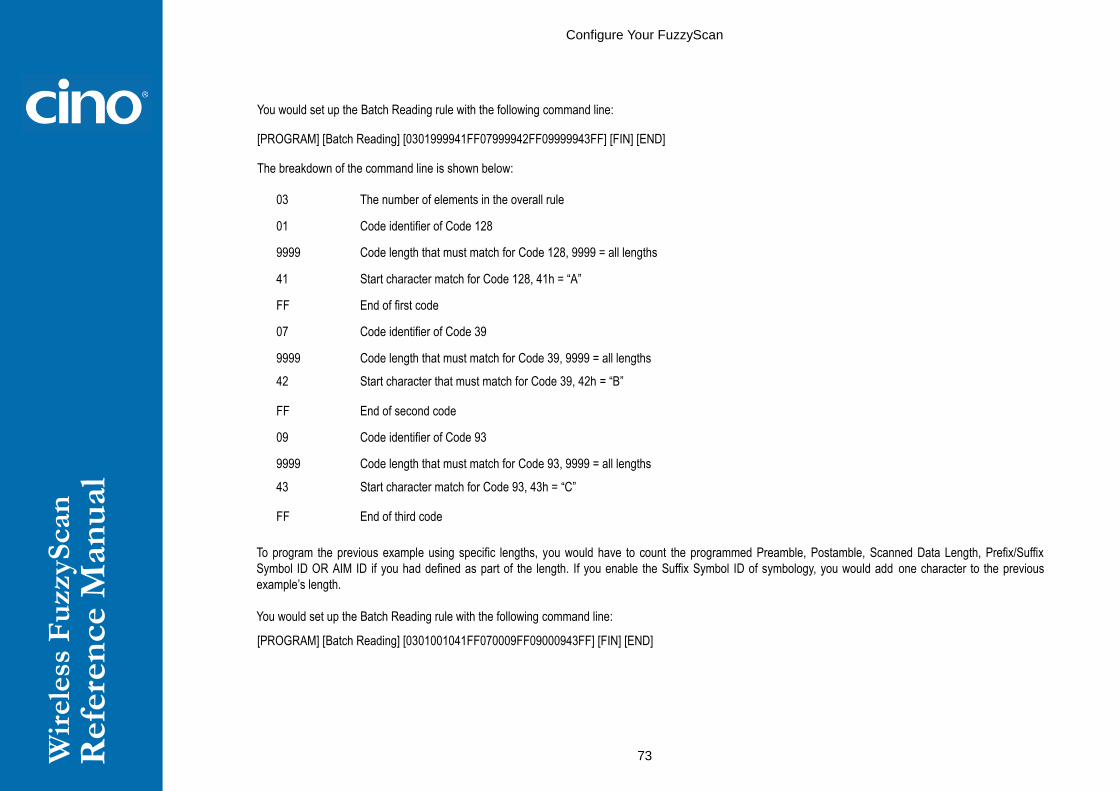
Wir
ele
ss F
uzzyS
can
R
efe
ren
ce M
an
ual
Configure Your FuzzyScan
73
You would set up the Batch Reading rule with the following command line:
[PROGRAM] [Batch Reading] [0301999941FF07999942FF09999943FF] [FIN] [END]
The breakdown of the command line is shown below:
03 The number of elements in the overall rule
01 Code identifier of Code 128
9999 Code length that must match for Code 128, 9999 = all lengths
41 Start character match for Code 128, 41h = “A”
FF End of first code
07 Code identifier of Code 39
9999 Code length that must match for Code 39, 9999 = all lengths
42 Start character that must match for Code 39, 42h = “B”
FF End of second code
09 Code identifier of Code 93
9999 Code length that must match for Code 93, 9999 = all lengths
43 Start character match for Code 93, 43h = “C”
FF End of third code
To program the previous example using specific lengths, you would have to count the programmed Preamble, Postamble, Scanned Data Length, Prefix/Suffix
Symbol ID OR AIM ID if you had defined as part of the length. If you enable the Suffix Symbol ID of symbology, you would add one character to the previous
example’s length.
You would set up the Batch Reading rule with the following command line:
[PROGRAM] [Batch Reading] [0301001041FF070009FF09000943FF] [FIN] [END]

Wir
ele
ss F
uzzyS
can
R
efe
ren
ce M
an
ual
Configure Your FuzzyScan
74
The breakdown of the command line is shown below:
03 The number of elements in the overall rule
01 Code identifier of Code 128
0010 Code length that must match for Code 128
A-CODE128 sample length (9) plus Suffix Symbol ID (1) = 10
41 Start character match for Code 128, 41h = “A”
FF End of first code
07 Code identifier of Code 39
0009 Code length that must match for Code 39
B-CODE39 sample length (8) plus Suffix Symbol ID (1) = 9
FF Universal matched character, indicating all character
Also indicate end of second code
09 Code identifier of Code 93
0009 Code length that must match for Code 93
C-CODE93 sample length (8) plus Suffix Symbol ID (1) = 9
43 Start character match for Code 93, 43h = “C”
FF End of third code
Note: If the [Character match(es)] is set to “FF”, the following “FF” which indicated the end of the code was not need to set.
- Structure of Data String
STX
(RS232/USB COM
interface)
Preamble Scanned Data
Length
Prefix Symbol ID
Or
Prefix AIM Symbol ID
Scanned Data modified
by DataWizard
Suffix Symbol ID
Or
Suffix AIM Symbol ID
Postamble ETX
(RS232/USB COM
interface)
1 character 1-15 characters 2-4 digits 1 or 3 characters Variable length 1 or 3 characters 1-15 characters 1 character

Wir
ele
ss F
uzzyS
can
R
efe
ren
ce M
an
ual
Configure Your FuzzyScan
75
PROGRAM
Operation Control
(All Series) Buzzer, Indicator, Vibrator, 1D Code Inverse Reading
F_DEFAULT
Family Code Selection P.C Parameter Selection Option Code
Buzzer Tone Adjust
SS
SS
SS
SS
SS
SS
SS
Buzzer tone – mute
Buzzer tone – low (Frequency 1.20 kHz)
Buzzer tone – medium (Frequency 2.70 kHz)
Buzzer tone – high (Frequency 2.81 kHz)
Buzzer tone - extremely high (Frequency 2.93 kHz)
Power-on / power-off beep
No power-on / power-off beep
0
1
2
3
4
5
6
Power On Indicator
SS
SS
SS
Disable (LED off)
LED steady on
LED flash
0
1
2
Good Read Indicator
SS
SS
Disable
Enable
0
1
Vibrator Control
SS
SS
Disable
Enable
Optional function, only available for vibrator model.
0
1
1D Barcode Inverse Reading
SS
SS
Disable
Enable
0
1

Wir
ele
ss F
uzzyS
can
R
efe
ren
ce M
an
ual
Configure Your FuzzyScan
76
PROGRAM
Operation Control
(All Series) Beeping Control, Radio connection Beeps
F_DEFAULT
Family Code Selection P.C Parameter Selection Option Code
Beeping Control
SS
SS
SS
SS
Radio Connected/ Disconnected Beep On
Radio Connected/ Disconnected Beep Off
Battery Power Low Beep On
Battery Power Low Beep Off
0
1
2
3
Radio Connection Beeps
SS
SS
Four ascending tone / Four descending tone
Low-high two beeps / High-low two beeps
0
1

Wir
ele
ss F
uzzyS
can
R
efe
ren
ce M
an
ual
Configure Your FuzzyScan
77
PROGRAM
Operation Control
(A Series & PA Series) Buzzer Volume
F_DEFAULT
Family Code Selection P.C Parameter Selection Option Code
Buzzer Volume
SS
SS
SS
Low
Medium
High
0
1
2
Available firmware: A770BT 1.00.13 and above; 2.00.03 and above
A670BT 1.00.01 and above
PA670BT 1.00.01 and above

Wir
ele
ss F
uzzyS
can
R
efe
ren
ce M
an
ual
Configure Your FuzzyScan
78
PROGRAM
Operation Control
(A Series & PA Series) Timestamp Functions –
Set Date, Set Time, Timestamp Format Setting
F_DEFAULT
Family Code Selection P.C Parameter Selection Option Code
Set Date
SS
Scan Date (MMDDYY)
For example, 2014-12-24, set 122414
6 digits + END
Set Time
SS
Set Time (HHMM)
For example, for 24-hour clock Time Conversion, 14:56 set 1456
4 digits + END
Timestamp Format Setting
SS
SS
SS
SS
SS
SS
SS
SS
SS
SS
SS
SS
SS
SS
SS
SS
SS
HH:MM DD/MM/YYYY
HH:MM MM/DD/YYYY
HH:MM YYYY/MM/DD
HH:MM:SS DD/MM/YYYY
HH:MM:SS MM/DD/YYYY
HH:MM:SS YYYY/MM/DD
DD/MM/YYYY HH:MM
MM/DD/YYYY HH:MM
YYYY/MM/DD HH:MM
DD/MM/YYYY HH:MM:SS
MM/DD/YYYY HH:MM:SS
YYYY/MM/DD HH:MM:SS
DD/MM/YYYY
MM/DD/YYYY
YYYY/MM/DD
HH:MM
HH:MM:SS
0
1
2
3
4
5
6
7
8
9
10
11
12
13
14
15
16

Wir
ele
ss F
uzzyS
can
R
efe
ren
ce M
an
ual
Configure Your FuzzyScan
79
PROGRAM
Operation Control
(A Series & PA Series) Timestamp Functions – Date & Time Format Setting,
Timestamp Output Control,
Stored Data Output Format, Online Mode Output Format
F_DEFAULT
Family Code Selection P.C Parameter Selection Option Code
Date & Time Format Setting
SS
SS
SS
SS
12 hour
24 hour
Short Year (YY)
Full Year (YYYY)
0
1
2
3
Timestamp Output Control
SS
SS
SS
SS
None
Batch mode
Online mode
Online mode & Batch mode
0
1
2
3
Stored Data Output Format
SS
SS
SS
SS
SS
SS
SS
SS
SS
SS
SS
Data/Record
Quantity + Data/Record
Data/Record + Quantity
Timestamp + Data/Record
Data/Record + Timestamp
Timestamp + Quantity + Data/Record
Timestamp + Data/Record + Quantity
Quantity + Timestamp + Data/Record
Quantity + Data/Record + Timestamp
Data/Record + Timestamp + Quantity
Data/Record + Quantity + Timestamp
0
1
2
3
4
5
6
7
8
9
10
Online Mode Output Format
SS
SS
SS
Data/Record
Timestamp + Data/Record
Data/Record + Timestamp
0
1
2
Timestamp Function is available for both Online Mode and Batch Mode.

Wir
ele
ss F
uzzyS
can
R
efe
ren
ce M
an
ual
Configure Your FuzzyScan
80
PROGRAM
Operation Control
( PF, PL &PA Series) Radio Link Mode for Discoverable Mode
F_DEFAULT
Family Code Selection P.C Parameter Selection Option Code
Radio Link Mode for
Discoverable Mode
SS
SS
SS
SS
HID Mode
HID Mode with Passkey
HID Legacy Mode
SPP Slave Mode
You may also press FN1 of pocket scanner for more than 3 seconds to enter
discoverable mode.
0
1
2
3

Wir
ele
ss F
uzzyS
can
R
efe
ren
ce M
an
ual
Configure Your FuzzyScan
81
PROGRAM
Operation Control
(All Series) Redundancy
F_DEFAULT
Family Code Selection P.C Parameter Selection Option Code
Redundancy
SS
SS
SS
SS
SS
SS
None
Level 1
Level 2
Level 3
Level 4
Level 5
To prevent potential miss reading.
0
1
2
3
4
5
The Redundancy is the number of times the same bar code label has to be decoded before it is transmitted.

Wir
ele
ss F
uzzyS
can
R
efe
ren
ce M
an
ual
Configure Your FuzzyScan
82
PROGRAM
Operation Control
(All Series) Delay Setting
F_DEFAULT
Family Code Selection P.C Parameter Selection Option Code
Reread Delay
(Double Scan Verification)
SS
SS
SS
SS
SS
SS
Disable
Immediate time out
Short time out
Medium time out
Long time out
Force verification
0
1
2
3
4
5
Good Read Delay
SS
SS
SS
SS
SS
SS
SS
None
200 msec.
500 msec.
1 sec.
1.5 sec.
2 sec.
3 sec.
0
1
2
3
4
5
6
HID Mode Transmit Delay SS
MS
None
1-250 msec.
Scan 3 digits from the option code chart in Appendix, then FuzzyScan will terminate
this selection automatically.
FIN
(3 digits)
The Reread Delay (Double Scan Verification) is designed to inhibit FuzzyScan from reading the same bar code label twice in pre-defined short duration. Force Verification
will not allow reading of the same bar code twice.
This Good Read Delay is the minimum amount of time before the scanner can read another bar code.
This HID Mode Transmit Delay will affect HID mode; When the scanner pairs with the Android, set this to 70ms to avoid data loss.

Wir
ele
ss F
uzzyS
can
R
efe
ren
ce M
an
ual
Configure Your FuzzyScan
83
PROGRAM
Operation Control
(All Series) Time-out Setting, Good Read Duration
F_DEFAULT
Family Code Selection P.C Parameter Selection Option Code
Light Source On Time
SS
SS
SS
SS
Short
Medium
Long
Extremely long
0
1
2
3
Hands Free Time-out
SS
SS
SS
SS
SS
Short
Medium
Long
Extremely long
Disable
0
1
2
3
4
Good Read Duration
SS
SS
SS
SS
SS
Short
Medium
Long
Extremely long
Extremely short
0
1
2
3
4
Time Delay to Low Power Standby Mode
SS
SS
SS
SS
SS
SS
1 sec
3 secs
5 secs
7 secs
9 secs
Immediate
0
1
2
3
4
5
Low Power Standby mode Link Indication
SS
SS
SS
Turn off immediately
Last for 1 minute
Keep on till power-off
0
1
2
The Light Source On Time is a pre-defined light source time out counter for Alternative Mode, Presentation Mode and Level Mode. The scanner keeps the light source on
till the pre-defined light source on time is up. You can adjust this parameter to meet your own application requirement.
The Pesentation Mode is referred to as “hands free” mode. The hands free mode will be automatically changed to manual trigger mode when you press the trigger. You
can remain the scanner in manual trigger mode by setting the Hands Free Time-Out. Once the time-out duration is up (if there’s no any trigger operation), the imager will
revert to the original hands free mode.

Wir
ele
ss F
uzzyS
can
R
efe
ren
ce M
an
ual
Configure Your FuzzyScan
84
The Time Delay to Low Power Standby Mode sets the time for scanner to enter low power trigger mode after any scanning activity.
Use Good Read Duration (Good Read Beep and Vibration Duration) to define beeps and vibration according to operator preference and work environment.

Wir
ele
ss F
uzzyS
can
R
efe
ren
ce M
an
ual
Configure Your FuzzyScan
85
PROGRAM
Operation Control
(All Series) Presentation Scanning Setting
F_DEFAULT
Family Code Selection P.C Parameter Selection Option Code
Presentation Auto-sense
SS
SS
Disable
Enable
0
1
Presentation Sensitivity
SS
SS
SS
SS
SS
Level 1
Level 2
Level 3
Level 4
Level 5
Level 6
Level 7
0
1
2
3
4
5
6
When enable the Presentation Auto-sense, the scanner can be switched between hands free scanning and hand-held scanning automatically when working with the
SmartStand or cradle.
The Presentation Sensitivity is used to configure the sensitivity level when the scanner is set as presentation mode. The higher lever means higher sensitivity for detecting
the barcode.

Wir
ele
ss F
uzzyS
can
R
efe
ren
ce M
an
ual
Configure Your FuzzyScan
86
PROGRAM
Operation Control
(F, L, PF & PL Series) Scan Rate Control,
F_DEFAULT
Family Code Selection P.C Parameter Selection Option Code
Scan Rate Control
SS
SS
Dynamic
Fixed
0
1
Scan Rate Control: The scanner will have better motion tolerance when you select “Fixed” scan rate. It’s suitable for application which needs higher motion tolerance on
the move. But this may impact to the reading distance.

Wir
ele
ss F
uzzyS
can
R
efe
ren
ce M
an
ual
Configure Your FuzzyScan
87
PROGRAM
Operation Control
(L & PL Series) Smart stand Power Off Timeout, Laser Aiming Control,
LED Illumination Control
F_DEFAULT
Family Code Selection P.C Parameter Selection Option Code
SmartStand Power Off Timeout
SS
SS
SS
3 mins
5 mins
10 mins
Only available for FuzzyScan L series scanners.
0
1
2
Laser Aiming Control SS
SS
Disable
Enable
0
1
LED Illumination Control
SS
SS
Always on
Intelligent Mode
0
1
LED Illumination Delay
SS
SS
SS
SS
SS
100 ms
150 ms
200 ms
250 ms
300 ms
0
1
2
3
4
The SmartStand Power Off Timeout is a pre-defined duration for scanner’s light source on time when the scanner is placed on SmartStand. While the scanner is placed
on SmartStand, the scanner will be switched from hand-held scanning to presentation scanning and the light source will be forced on automatically. The light source will be
off when the pre-defined duration is up.
Laser Aiming Control: You can disable or enable laser aiming line when you scan PDF barcode.
LED Illumination Control: When you enable “always on“, the LED illumination will be always on when you press the trigger. When you enable “intelligent mode”,
the scanner will emit the laser aiming line first, the LED illumination will be turned on after the preset LED illumination delay. Intelligent mode is recommended
to be used in regular ambient light environment.

Wir
ele
ss F
uzzyS
can
R
efe
ren
ce M
an
ual
Configure Your FuzzyScan
88
PROGRAM
Operation Control
(A Series & PA Series) Aiming Control, Delay Aiming & Decode Aiming Control
F_DEFAULT
Family Code Selection P.C Parameter Selection Option Code
Illumination Control
SS
SS
Disable
Enable
0
1
Presentation Background Lighting
SS
SS
LEDs Off
LEDs On
0
1
Aiming Control
SS
SS
SS
Regular Aiming
Intelligent Aiming
Delay Aiming Control
0
1
2
Delay Aiming Time-out Control
SS
SS
SS
SS
200 ms
400 ms
800 ms
1 sec
1.5 secs.
2 secs.
3 secs.
4 secs.
0
1
2
3
4
5
6
7
Decode Aiming Control
SS
SS
SS
SS
Disable in Hand-Held mode
Enable in Hand-Held mode
Disable in Hand-Free mode
Enable in Hand-Free mode
0
1
2
3
The Illumination Control is only available for hand-held mode.
Presentation Background Lighting Control: You can enable or disable presentation background lighting of the scanner according to the ambient light condition in presentation mode. When the ambient light is dim or dark, you can enable this function to turn on the scanner’s LED illumination at a dim level. This is helpful for scanner to detect the motion of scene.
The Aiming Control is only available for trigger mode. In Intelligent Aiming, the aiming light is turned on when the scanner is lifted. A trigger pull activates decoding process.
After 2 seconds of inactivity, the aiming light will be shut off. Delay Aiming Control allows a delay time for the operator to aim the scanner before the image is taken. During
the delay time, the aiming light will be on, but the LED illumination won’t be turned on until the delay time is up.
The Delay Aiming Time-out Control is only available for trigger mode. You can use Delay Aiming Time-out Control to set the delay time.

Wir
ele
ss F
uzzyS
can
R
efe
ren
ce M
an
ual
Configure Your FuzzyScan
89
PROGRAM
Operation Control
(A Series & PA Series) Center Alignment, Unique Bar Code Reporting
F_DEFAULT
Family Code Selection P.C Parameter Selection Option Code
Center Alignment SS
SS
SS
SS
Disable in Hand-Held Mode
Enable in Hand-Held Mode
Disable in Hand-Free Mode
Enable in Hand-free Mode
0
1
2
3
Unique Bar Code Reporting
SS
SS
Disable
Enable
0
1
Center Alignment: When this function is enabled, the scanner only decodes barcode(s) around aiming line.
Unique Bar Code Reporting: When this function is enabled, the scanner only outputs unique barcode when the trigger is pressed. This function is workable when Multiple
Read mode is selected.

Wir
ele
ss F
uzzyS
can
R
efe
ren
ce M
an
ual
Configure Your FuzzyScan
90
PROGRAM
Operation Control
(All Series) Out-of-range Scanning, Link Supervision Time-out
F_DEFAULT
Family Code Selection P.C Parameter Selection Option Code
Out-of-range Scanning
SS
SS
Disable
Enable
0
1
Out-of-range Scanning - When radio link is built between the scanner and remote host device, the scanner will transmit each scanned data right after scanning the
barcode data. However, the scanner is preset for unable to scan any barcode data when it loses the radio connection. You can enable the Out-of-range Scanning function
to continue scanning barcode data into memory buffer until radio link resumed.
.

Wir
ele
ss F
uzzyS
can
R
efe
ren
ce M
an
ual
Configure Your FuzzyScan
91
PROGRAM
Operation Control
(All Series) Radio-off Time-out Control, Power Off Time-out Control
F_DEFAULT
Family Code Selection P.C Parameter Selection Option Code
Radio-off Time-out
- Connect State
SS
MS
12 (x5) minutes
0-99 (x5) minutes
If you don’t want the scanner to enter power-off, please set time-out to “0”
FIN
(2 digits)
Radio-off Time-out
- Disconnect State
SS
MS
5 (x1) minute
0-99 (x1) minutes
If you don’t want the scanner to enter power-off, please set time-out to “0”
FIN
(2 digits)
Power Off Time-out SS
MS
1 (x5) minutes
0-99 (x5) minutes
If you want the scanner to enter power off mode immediately, please set time-out to
“0”
FIN
(2 digits)
The Radio-off Time-out Control can be set under radio connection or disconnection state. If the scanner is not used within the preset time-out duration, it will automatically
enter “Power Off” for power saving purpose. You are able to disable this function by setting the time-out duration to “0”.
The Power Off Time-out: When the scanner is under radio-off, it is preset to enter Power Off automatically if the radio is not on after the time-out duration. If you would like
to power on the scanner, please press the trigger button. You can have the scanner enter this function immediately by setting the time-out duration to “0”
Above behavior (revised from Programming Manual rev. C7) is available for firmware
F680BT, F780BT, L680BT, L780BT: 3.01.09 and above; 4.00.06 and above
A770BT: 1.00.15 and above, 2.00.04 and above
A670BT: 1.00.01 and above
PF/ PL680BT: 1.00.06 and above
PA670BT: 1.00.02 and above

Wir
ele
ss F
uzzyS
can
R
efe
ren
ce M
an
ual
Configure Your FuzzyScan
92
PROGRAM
Operation Control
( PF, PL &PA Series) FN2 Function Mode Setting
F_DEFAULT
Family Code Selection P.C Parameter Selection Option Code
FN2 Function Mode
SS
SS
Batch Scanning
Validation Scanning
0
1
The FN2 Function Mode: The Batch Scanning (Inventory Mode) is set as the default FN2 function mode. Batch Scanning and Validation Scanning can’t be used at the
same time. If you want to use Function Key of pocket scanner to carry out Validation Scanning, you have to change the default setting.

Wir
ele
ss F
uzzyS
can
R
efe
ren
ce M
an
ual
Configure Your FuzzyScan
93
PROGRAM
Operation Control
(All Series) Batch Scanning Setting
F_DEFAULT
Family Code Selection P.C Parameter Selection Option Code
Batch Scanning Link Control
SS
SS
Radio disable
Radio enable
0
1
Stored Data Transmission
SS
SS
SS
All
On cradle
Scan barcode
0
1
2
Delete Stored Data after
Transmission
SS
SS
Disable
Enable
0
1
The Batch Scanning Link Control is a pre-defined radio option to control the radio-on or radio-off status under batch scanning operation. Please note that if the radio
disable is activated, the radio link will be disconnected once you enter batching scanning. The radio link will be resumed when you transmit the stored data or exit batch
scanning.
The Stored Data Transmission is a pre-defined approach when you want to transmit the scanned data under batch scanning operation. You can transmit the scanned data
by placing the scanner onto the cradle or scanning “Transmit Stored Data” command, or by either one of both methods.
In batching scanning, the default setting of Delete Stored Data after Transmission is disable. The scanner will keep all stored data after transmission until you scan the
“Clear All Stored Data” command. You are also able to delete all stored data after transmission automatically by enabling this function.

Wir
ele
ss F
uzzyS
can
R
efe
ren
ce M
an
ual
Configure Your FuzzyScan
94
PROGRAM
Operation Control
(All Series) Batch Scanning Data Transmission Setting
F_DEFAULT
Family Code Selection P.C Parameter Selection Option Code
Field Delimiter
SS
SS
SS
SS
SS
SS
None
,
SPACE
–
.
User define
0
1
2
3
4
5, [00-7F]
Stored Data Output Format
SS
SS
SS
As many times as the quantity indicates
<Quantity><Field Delimiter><Scanned Data>
<Scanned Data><Field Delimiter><Quantity>
0
1
2
Data Transmission Format
SS
SS
SS
Disable (scanned data only)
Leading with MAC address (MAC address and scanned data)
Leading with ID No. (scanner ID and scanned data)
Only available for RS232, USB HID and USB COM interface in PAIR & PICO modes
0
1
2
The Field Delimiter is used to separate the specific information and scanned data into two fields. You can choose desired delimiter format.
The Stored Data Output Format If you want to input the quantity information of barcode data, you can enter the quantity from 1 to 9999 by scanning the quantity barcodes
right after you scanned the barcode data. The quantity information will be stored into the memory storage together with the barcode data. There are three ways to output the
stored barcode data and quantity information.
In PICO mode, up to 7 scanners can be connected with one smart cradle. The Data Transmission Format can help user to identify the source of the transmitted data.
You can choose to transmit the scanned data leading with MAC address or pre-assigned ID.
Example format: <MAC address><Field Delimiter><Data> or <ID><Field Delimiter><Data>.

Wir
ele
ss F
uzzyS
can
R
efe
ren
ce M
an
ual
Configure Your FuzzyScan
95
PROGRAM
Operation Control
(All Series) Validation Scanning Setting
F_DEFAULT
Family Code Selection P.C Parameter Selection Option Code
Validation Mode Link Control
SS
SS
Radio Disabled
Radio Enabled
0 1
Master Data Setting
SS
SS
Single master data
Multiple master data
0
1
Validation Output SS
SS
SS
SS
SS
SS
Disable data transmission
Transmit valid data
Transmit invalid data
Transmit valid data or “NG”
Transmit invalid data or “OK”
Transmit “OK” or “NG”
0 1 2 3
4
5
6
The Validation Mode Link Control is a pre-defined radio option to control the radio-on or radio-off status under Validation Scanning operation. Please note that if the radio
disable is activated, the radio link will be disconnected once you enter Validation Scanning. The radio link will be resumed when you enable data transmission or exit
Validation Scanning.
The Master Data Setting: The default Master Data Setting is preset to “Single Master Data”. If Single Master Data is selected, though you can scan multiple master data
continuously, only the last master data will be valid, and the master data registered previous to the last master data will be cleared. If the multiple master data is required,
you have to change the default setting. The scanner is capable of storing up to 2K byes master data.
The Validation Output (Validation Result Output) is preset to”Disable data transmission”. There are six ways to output the validation result.
Above behavior (revised from Programming Manual rev. C14) is available for firmware
A770BT series: Rev. 2.00.05 and above
A670BT series: Rev. 1.00.02 and above
F780BT and L780BT series: Rev. 4.00.08 and above
F680BT and L680BT series: Rev. 4.00.08 and above

Wir
ele
ss F
uzzyS
can
R
efe
ren
ce M
an
ual
Configure Your FuzzyScan
96
PA670BT series: Rev. 1.00.04 and above
PF680BT and PL680BT series: Rev. 1.00.09 and above

Wir
ele
ss F
uzzyS
can
R
efe
ren
ce M
an
ual
Configure Your FuzzyScan
97
PROGRAM
Operation Control
(All Series) Bluetooth Device Name & Security Setting
F_DEFAULT
Family Code Selection P.C Parameter Selection Option Code
Bluetooth Device Name
SS
MS
Default device name
User define;
F/L series: 1-16 characters
A series: 1-32 characters
FIN
[00-7F], FIN
Bluetooth PIN Code
SS
MS
Default Bluetooth PIN Code
User define, 1-8 numbers
FIN
[30-39], FIN
Bluetooth Authentication
SS
SS
Disable
Enable
0
1
The default Bluetooth Device Name for F/L series is “F(L)xxxBT-xxxx”, and for PF/PL series is PF(L)xxxBT-xxxx, you will be able to change the device name by scanning
HEX values (1-16 characters).
The default Bluetooth Device Name for A series is “AxxxBT-xxxx”, you will be able to change the device name by scanning HEX values (1-32 characters).
The default Bluetooth PIN Code is “00000000”, you will be able to change the PIN Code by scanning HEX values (1-8 numbers).
The Bluetooth Authentication You can enable or disable the Bluetooth Authentication between the scanner and remote host device. If this function is enabled, when the
scanner wants to connect itself and sends the data to the host device, the host device has to return a link key shared between the scanner and the host device.

Wir
ele
ss F
uzzyS
can
R
efe
ren
ce M
an
ual
Configure Your FuzzyScan
98
PROGRAM
Operation Control
Bluetooth Other Settings
F_DEFAULT
Family Code Selection P.C Parameter Selection Option Code
Bluetooth Sniff Control SS
SS
Disable
Enable
0
1
Link Quality Control SS
SS
SS
SS
SS
Disable
Level 1
Level 2
Level 3
Level 4
0
1
2
3
4
The Bluetooth Sniff Control Bluetooth module will enter low power consumption mode when you enable this function.
Link Quality Control: This function is only available for SPP and HID mode. When you use the scanner in the boundary of radio signal, you can enable this function to
increase the reliability of data transmission. But this function will affect the communication distance. The level is higher, the communication distance is shorter.

Wir
ele
ss F
uzzyS
can
R
efe
ren
ce M
an
ual
Configure Your FuzzyScan
99
PROGRAM
Operation Control
(All Series) On-screen Keyboard Control
F_DEFAULT
Family Code Selection P.C Parameter Selection Option Code
On-screen Keyboard Control
SS
SS
Disable
Enable
0
1
When On-screen Keyboard Control is enabled, the scanner is preset to switch between barcode scanning and on-screen keyboard of most popular devices; you also can
have the scanner entered this setting by scanning “General Approach “ quick set command. Then you can turn off the radio to activate the on-screen keyboard by
scanning “Switch On-screen Keyboard” quick set command. If you use pocket scanner, you can activate the on-screen keyboard toggle by short pressing the FN1.
To work with iOS device, please change On-screen Keyboard Control to disable, or scan the “iOS Approach” quick set command to activate this function. Then you can
scan ““Switch On-screen Keyboard” quick set command to toggle the iOS on-screen keyboard. If you use pocket scanner, you can also activate the iOS on-screen
keyboard toggle by short pressing the FN1.
When you finished the keyboard input, please press the trigger once to turn on the radio, and the on-screen keyboard will be inactivated.

Wir
ele
ss F
uzzyS
can
R
efe
ren
ce M
an
ual
Configure Your FuzzyScan
100
PROGRAM
Condensed DataWizard
Preamble, Postamble, Data Length & Symbol ID Trans.
F_DEFAULT
Family Code Selection P.C Parameter Selection Option Code
Preamble
SS
MS
None
1-15 characters
Maximum 15-character input; scan “FIN” to terminate this selection.
FIN
[00-7F], [FIN]
Postamble
SS
MS
None
1-15 characters
Maximum 15-character input; scan “FIN” to terminate this selection.
FIN
[00-7F], [FIN]
Data Length Transmission
SS
SS
Disable
Enable 2 digits data length transmission
If data length exceeds 99, 3-digit data length will be transmitted.
0
1
Symbology ID Transmission
SS
SS
SS
SS
SS
SS
SS
Disable symbology ID transmission
Enable prefix symbology ID transmission
Enable suffix symbology ID transmission
Enable both prefix and suffix symbology ID transmission
Enable prefix AIM symbology ID transmission
Enable suffix AIM symbology ID transmission
Enable both prefix and suffix AIM symbology ID transmission
0
1
2
3
4
5
6
DataWizard is the most powerful, Artificial-Intelligence based data editing expert system provided specially for the FuzzyScan family bar code readers. Through DataWizard,
you can process the scanned data prior the transmissions in many ways as: Insert Delete, Match, Verify, Replace, Reorganize, and Repeat Transmission. It will help
you to arrange the transmission of scanned data to any specific format without software modification.
Due to the resources used by this system, Full-feature DataWizard is only supported by PowerTool. Through the PowerTool, all settings and configurations can be done
on-screen, under Windows 95/98/NT/2000/XP environment.
A Condensed Version DataWizard is provided by each FuzzyScan series. Through this menu, the condensed DataWizard can be utilized via bar code menu readings with
ease.
Please note that all “Character” input should be referred to the ASCII/HEX Table listed in Appendix to find matched HEX value.
If you have any problem to use DataWizard, please refer to following pages for details and consult your local FuzzyScan vendor or our web site for any assistance.

Wir
ele
ss F
uzzyS
can
R
efe
ren
ce M
an
ual
Configure Your FuzzyScan
101
PROGRAM
Condensed DataWizard
Data Formatter Setting
F_DEFAULT
Family Code Selection P.C Parameter Selection Option Code 2nd Option Code
Formatter Control
SS
MS
MS
Disable
Select one bar code symbology
Select all bar code symbologies
FIN
(2 digits)
00
automatic termination
automatic termination
1st Insertion
SS
DS
Disable
Enable
2-digits identified position; max. 3 insertion characters
FIN
(2 digits)
position
[1-3 characters], [FIN]
2nd Insertion
SS
DS
Disable
Enable
2-digits identified position; max. 3 insertion characters
FIN
(2 digits)
position
[1-3 characters], [FIN]
3rd Insertion
SS
DS
Disable
Enable
2-digits identified position; max. 3 insertion characters
FIN
(2 digits)
position
[1-3 characters], [FIN]
4th Insertion
SS
DS
Disable
Enable
2-digits identified position; max. 3 insertion characters
FIN
(2 digits)
position
[1-3 characters], [FIN]
The Data Formatter is used to edit the scanned raw data prior to transmitting the data to the host computers or terminals. It allows you to select desired bar code
symbologies for formatter control, and provides Multiple Position Insertion and Multiple Character Insertion (max three characters) in the identified position.
While the Data Formatter is enabled, it arranges only scanned data without Preamble, Postamble, STX, ETX, Data Length, Prefix/Suffix Symbolology ID or Record
Suffix. All of the above programmable parameters perform the same function depending on your setting.
Regarding the “Bar Code Selection” and “Position Calculation” of data formatter, please refer to page 60 for details.
Please note that all “Character” input should be referred to the ASCII/HEX Table listed in Appendix to find matched HEX value.

Wir
ele
ss F
uzzyS
can
R
efe
ren
ce M
an
ual
Configure Your FuzzyScan
102
PROGRAM
Condensed DataWizard
Data Verifier Setting
F_DEFAULT
Family Code Selection P.C Parameter Selection Option Code 2nd Option Code
Verifier Control
SS
MS
MS
Disable
Select one bar code symbology
Select all bar code symbologies
FIN
(2 digits)
00
automatic termination
automatic termination
Identified Data Length
SS
MS
Disable
Enable
Determine the identified data length for verification.
FIN
(2 digits)
1st Identified Character
SS
DS
Disable
Enable
2-digits checking position; 1 identified character
FIN
(2 digits)
position
[00-7F]
2nd Identified Character
SS
DS
Disable
Enable
2-digits checking position; 1 identified character
FIN
(2 digits)
position
[00-7F]
3rd Identified Character
SS
DS
Disable
Enable
2-digits checking position; 1 identified character
FIN
(2 digits)
position
[00-7F]
The Data Verifier is used to provide advanced verification for error-free scanning and to work as an Embedded Data Transmitting Filter.
All data must conform to the Identified Bar Code Symbologies, Identified Data Length, and one to three Identified Characters in the checking position. Otherwise, the
FuzzyScan will not transmit the data to the host computers or terminals, but will instead issue 3 long beeps for verification error and skip the scanned data.
The Data Verifier checks only scanned data without Preamble, Postamble, STX, ETX, Data Length, Prefix/Suffix Symbology ID or Record Suffix.
Regarding the “Bar Code Selection” and “Position Calculation” of Data Verifier, please refer to page 60 for details.
Please note that all “Character” input should be referred to the ASCII/HEX Table listed in Appendix to find matched HEX value.

Wir
ele
ss F
uzzyS
can
R
efe
ren
ce M
an
ual
Configure Your FuzzyScan
103
PROGRAM
Condensed DataWizard
Data Replacer Setting
F_DEFAULT
Family Code Selection P.C Parameter Selection Option Code 2nd Option Code
Replacer Control
SS
MS
MS
Disable
Select one bar code symbology
Select all bar code symbologies
FIN
(2 digits)
00
automatic termination
automatic termination
1st Replacement
SS
DS
Disable
Enable
2-digits identified position; 1 replacement character
FIN
(2 digits)
position
[00-7F]
2nd Replacement
SS
DS
Disable
Enable
2-digits identified position; 1 replacement character
FIN
(2 digits)
position
[00-7F]
3rd Replacement
SS
DS
Disable
Enable
2-digits identified position; 1 replacement character
FIN
(2 digits)
position
[00-7F]
The Data Replacer is used to edit the scanned raw data prior to transmitting the data to the host computers or terminals. It allows you to select desired bar code
symbologies for replacer control, and provides Multiple Position Replacement in the identified position.
All data must conform to the Identified Bar Code Symbologies, and one to three Identified Characters in the identified position while the Data Replacer is enabled, it
arranges only scanned data without Preamble, Postamble, STX, ETX, Data Length, Prefix/Suffix Symbology ID or Record Suffix.
Regarding the “Bar Code Selection” and “Position Calculation” of Data Replacer, please refer to page 60 for details.
Please note that all “Character” input should be referred to the ASCII/HEX Table listed in Appendix to find matched HEX value.

Wir
ele
ss F
uzzyS
can
R
efe
ren
ce M
an
ual
Configure Your FuzzyScan
104
PROGRAM
Condensed DataWizard
Data Organizer Setting
F_DEFAULT
Family Code Selection P.C Parameter Selection Option Code 2nd Option Code
Organizer Control
SS
MS
MS
Disable
Select one bar code symbology
Select all bar code symbologies
FIN
(2 digits)
00
automatic termination
automatic termination
1st Organization
SS
DS
Disable
Enable
2-digits identified position;
Forward/backward data transmission setting
FIN
(2 digits)
position
direction
0 (Forward)
1 (Backward)
2nd Organization
SS
DS
Disable
Enable
2-digits identified position;
Forward/backward data transmission setting
FIN
(2 digits)
position
direction
0 (Forward)
1 (Backward)
Include/Exclude Control
SS
DS
Transmitted data excluded the data of identified position
Transmitted data included the data of identified position
0
1
The Data Organizer is used to edit the scanned raw data prior to transmitting the data to the host computers or terminals. It allows you to select desired bar code
symbologies for organizer control, and provides maximum two identified positions to send the data forward or backward. It also allows you to control the transmitted data
including or excluding the data of identification position. Please refer to the application example listed in page 60 for details.
While the Data Organizer is enabled, it arranges only scanned data without Preamble, Postamble, STX, ETX, Data Length, Prefix/Suffix Symbology ID or Record
Suffix.
Regarding the “Bar Code Selection” and “Position Calculation” of Data Organizer, please refer to page 60 for details.
Please note that all “Character” input should be referred to the ASCII/HEX Table.

Wir
ele
ss F
uzzyS
can
R
efe
ren
ce M
an
ual
Configure Your FuzzyScan
105
Select a Bar Code Symbology
You can select one or all types of bar code symbologies to
use Condensed DataWizard for advanced transmission
arrangement. If you scan “00” to select all types, the
FuzzyScan will arrange all incoming data to meet your
pre-defined format. If you want to select only one type bar
code, please select one of the option code listed below.
1D Bar Code Symbology
Code 128 01 Matrix 2 of 5 38
GS1-128 31 Interleaved 2 of 5 48
UPC-A 02 China Postal Code 58
UPC-A with 2 supplement 32 German Postal Code 68
UPC-A with 5 supplement 42 Standard/Industrial 2 of 5 08
UPC-E 03 Code 93 09
UPC-E with 2 supplement 33 Code 11 10
UPC-E with 5 supplement 43 MSI/Plessey 11
EAN-13 04 UK/Plessey 12
EAN-13 with 2 supplement 34 Telepen 13
EAN-13 with 5 supplement 44 GS1 DataBar 14
EAN-8 05 IATA 15
EAN-8 with 2 supplement 35 Coupon Code 16
EAN-8 with 5 supplement 45 PDF417 17
Codabar/NW-7 06 Codablock F 18
Code 39 07 Code 16K 19
Code 32 37 Code 49 20
Trioptic Code 39 47 GS1 DataBar Limited 22
GS1 DataBar Expanded 23
Composite Codes 24
Micro PDF417 25
2D Bar Code Symbology
QR Code A0 MaxiCode A2
MicroQR Code A0 Aztec Code A3
DataMatrix A1 Chinese Sensible Code A4
GS1 DataMatrix A5
Postal Code
Korea Post Code 21 Japanese Post B4
Australian Post B0 KIX Post B5
British Post B1 Planet Code B6
Intelligent Mail barcode B3 Postnet B8
Position Calculation
[Data Formatter]
If there is a 5-character input data string, refer to the
following to calculate the actual position for insertion:
X X X X X
00 01 02 03 04 05
[Data Verifier, Data Replacer, Data Organizer]
If there is a 11-character data string, please refer to the
following to calculate the actual position for identification.
X X X X X X X X X X X
00 01 02 03 04 05 06 07 08 09 10

Wir
ele
ss F
uzzyS
can
R
efe
ren
ce M
an
ual
Configure Your FuzzyScan
106
Application Example
If your bar code label is a 16-digit Interleaved 2 of 5 which
includes the information of 6-digit date code, 6-digit serial
number and 4-digit unit price, you want the FuzzyScan do the
following for you without software modification:
Apply only Interleaved 2 of 5 to the condensed
DataWizard.
Check bar code is actually with 16-digit length.
Allow bar code output whose date code is leading with “9”.
Three outputs with “TAB” suffix.
The date code output should skip “9” and replaced it by
“A”.
The serial number output should be led with “SN”.
The unit price output should be skipped the first 2 digits.
Test Bar Code : 9 8 1 0 2 5 1 2 3 4 5 6 9 8 7 6
Actual Output : A81025[TAB]SN123456[TAB]76[TAB]
Programming Procedure
[Data Verifier]
Scan “Program” to enter the programming mode.
Scan “Verifier Control” and set bar code symbology to
“48” (Interleaved 2 of 5).
Scan “Identified Data Length” and set the length to
“16”.
Scan “1st Identified Character” and set the identified
position to “00”, then set the identified character to “39”
(Hex Code of 9).
[Data Formatter]
Scan “Formatter Control” and set bar code symbology
to “48”.
Scan 1st Insertion” and set the identified position to
“06”, then inserted characters to “09” (Hex Code of
TAB), “53” (Hex Code of S), “4E” (Hex Code of N).
Scan “2nd Insertion” and set the identified position to
“12”, then inserted character to “09”. In the final, you
must scan “FIN” (Finish) code to terminate this
selection.
Scan “3rd Insertion” and set the identified position to
“16”, then inserted character to “09”. In the final, you
must scan “FIN” (Finish) code to terminate this
selection.

Wir
ele
ss F
uzzyS
can
R
efe
ren
ce M
an
ual
Configure Your FuzzyScan
107
[Data Replacer]
Scan “Replacer Control” and set bar code symbology to
“48”.
Scan “1st Replacement” and set the identified position to
“00”, then replaced character to “41” (Hex Code of A).
[Data Organizer]
Scan “Organizer Control” and set bar code symbology to
“48”.
Scan “1st Organization” and set the identified position to
“16”, then set the data transmission to “0” (forward).
Scan “2nd Organization” and set the identified position to
“17”, then set the data transmission to “1” (backward).
Scan “END” (Exit) to terminate the programming.
[Important Notice]
Please note that Condensed DataWizard will follow the
preset working flow as below:
Verifier Formatter Replacer Organizer
So when you set the identified position in Data Organizer,
you must consider the inserted data which you already set
via Data Formatter.

Wir
ele
ss F
uzzyS
can
R
efe
ren
ce M
an
ual
Appendix
108
Symbology ID Table
Each AIM Code Identifier contains the three-character string ]cm where:
] = Flag Character, c = Code Character, m = Modifier Character
Code Family Primary Format
Cino ID AIM ID
Code Family Primary Format
Cino ID AIM ID
Hex
value
Code
Chara
cter
Code
Charact
er
Modified
Character
Code
Charact
er
Code
Charac
ter
Code
Chara
cter
Modified
Character
UPC
UPC-A 2
A
E
0
EAN/JAN
EAN/JAN-8 05
N E
4
UPC-A with 2 supple. 32 1 EAN/JAN-8 with 2 supple. 35 1
UPC-A with 5 supple. 42 2 EAN/JAN-8 with 5 supple. 45 2
UPC-E 3
E
0 EAN/JAN-13 04
F E
0
UPC-E with 2 supple. 33 1 EAN/JAN-13 with 2 supple. 34 1
UPC-E with 5 supple. 43 2 EAN/JAN-13 with 5 supple. 44 2
Example: A UPC-A bar code 012345678950 with 2 supplement 12 is transmitted as ]E0012345678950]E112
Example: A EAN/JAN-8 bar code 49123562 with 5 supplement 12345 is transmitted as ]E449123562]E212345
Code 128 Code 128 01 B
C m Code 93 Code 93 09 H G m
GS1-128 31 C 1 Code 11 Code 11 10 P H m
Codabar Codabar/NW-7 06 D F m MSI/Plessey MSI/Plessey 11 R M m
Code 25
Standard/Industrial 2 of 5 08 I S 0 UK/Plessey UK/Plessey 12 S P 0
Matrix 2 of 5 38 K X 0 Telepen Telepen 13 T B m
Interleaved 2 of 5
48 J I m GS1 DataBar
GS1 Databar 14
X e m GS1 DataBar Limited 22
GS1 DataBar Expanded 23
China Postal Code 58 L X 0 Compsoite Composite Code 24
Code 39
Code 39 07 G A m
German Postal Code 68 M I m Code 39 Trioptic 47 W X 0
IATA IATA 15 O R m Code 32 37 G A 0
UCC Coupon
UCC Coupon Code Z PDF417 PDF417 17
V L m Micro PDF417 25
Example : A UPC-A 512345678900 + GS1-128 81010123451297 bar code is transmitted as]E0512345678900]C181010123451297
Example: A EAN-13 9923456789019 + GS1-128 81010123451297 bar code is transmitted as ]E09923456789019]C181010123451297
Codablock Codablock F 18 Y O m
Korea Post Korea Post Code 21 a X 0
Remark: Above examples are given for the transmission of AIM ID.

Wir
ele
ss F
uzzyS
can
R
efe
ren
ce M
an
ual
Appendix
109
2D Symbology ID Table
Code Family Primary Format
Cino ID AIM ID
Code Family Primary Format
Cino ID AIM ID
Hex
Value Char.
Code
Char.
Modified
Char.
Hex
Value
Char. Code
Char.
Modified
Char.
QR Code QR Code
A0 b Q m
British Post British Post B1 h
X
0
Micro QR Code
Micro QR Code Intelligent Mail barcode
Intelligent Mail barcode B3 j 0
Data Matrix Data Matrix A1
c d m Japanese Post
Japanese Post B4 k 0 GS1 Data Matrix A5
MaxiCode MaxiCode A2 d U m KIX Post KIX Post B5 l 0
Aztec Code Aztec Code A3 e z m Planet Code Planet Code B6 m 0
Chinese Sensible
Chinese Sensible A4 f
X
0 Postnet Postnet B8 o 0
Australian Post
Australian Post B0 g 0

Wir
ele
ss F
uzzyS
can
R
efe
ren
ce M
an
ual
Appendix
110
Keyboard Function Code Table
No. ANSI ASCII Key Function Ctrl Output No. ANSI ASCII Key Function Ctrl Output
00 NUL 00H RESERVED Ctrl + @ 16 DLE 10H F7 Ctrl + P
01 SOH 01H CTRL (Left) Ctrl + A 17 DC1 11H F8 Ctrl + Q
02 STX 02H ALT (Left) Ctrl + B 18 DC2 12H F9 Ctrl + R
03 ETX 03H SHIFT Ctrl + C 19 DC3 13H F10 Ctrl + S
04 EOT 04H CAPS LOCK Ctrl + D 20 DC4 14H F11 Ctrl + T
05 ENQ 05H NUM LOCK Ctrl + E 21 NAK 15H F12 Ctrl + U
06 ACK 06H ESC Ctrl + F 22 SYN 16H INS (Insert) (Edit) Ctrl + V
07 BEL 07H F1 Ctrl + G 23 ETB 17H DEL (Delete) (Edit) Ctrl + W
08 BS 08H BACK SPACE Ctrl + H 24 CAN 18H HOME (Edit) Ctrl + X
09 HT 09H TAB Ctrl + I 25 EM 19H END (Edit) Ctrl + Y
10 LF 0AH F2 Ctrl + J 26 SUB 1AH PAGE UP (Edit) Ctrl + Z
11 VT 0BH F3 Ctrl + K 27 ESC 1BH PAGE DOWN (Edit) Ctrl + [
12 FF 0CH F4 Ctrl + L 28 FS 1CH UP (Edit) Ctrl + \
13 CR 0DH ENTER (CR) Ctrl + M 29 GS 1DH DOWN (Edit) Ctrl + ]
14 SO 0EH F5 Ctrl + N 30 RS 1EH LEFT (Edit) Ctrl + 6
15 SI 0FH F6 Ctrl + O 31 US 1FH RIGHT (Edit) *see below note
To emulate the keyboard function key input for user definable parameters, user must configure actual content using the
Reserved ASCII 0 – 31 characters, and also Enable the “Function Key Emulation”. Otherwise, the Ctrl output will be done
by the scanner. Please refer to the above Keyboard Function Code Table which is for IBM PC/XT/AT, PS/2, PS/VP,
COMPAQ PC, HP Vectra PC, Notebook PC, APPLE and PowerMac, and WYSE PC Enhanced or fully compatible machines.
The last character in the Ctrl Output column is varied for different countries.
Country (refer to Keyboard Layout) & Character
United State - Switzerland - France =
Belgium - UK - Germany -
Sweden - Denmark - Norway -
Spain - Italy -

Wir
ele
ss F
uzzyS
can
R
efe
ren
ce M
an
ual
Appendix
111
ASCII Input Shortcut
To configure the user definable parameters of FuzzyScan via
programming menu, FuzzyScan will ask you to scan your
desired ASCII value in HEX form. You have to refer to the
“HEX/ASCII Table” for details.
Example:
If you want the scanned data output leading with a Dollar
Sign, you have to set the “Preamble” to “$”. The configuration
procedure is listed below for reference.
Scan the system command – PROGRAM listed on page
3-24 to enter programming mode.
Scan family code – PREAMBLE to select this family.
Refer to the Hex/ASCII Table, you will find the HEX value
of “$” is 24.
Scan the option code – 2 listed on the fold out back cover.
Scan the option code – 4 listed on the fold out back cover.
Scan the system command – FIN (Finish) to terminate
Preamble setting.
Scan the system command – End to exit the programming
mode for normal operation.
HEX/ASCII Reference Table
H
L 0 1 2 3 4 5 6 7
0 NUL DLE SPACE 0 @ P ` p
1 SOH DC1 ! 1 A Q a q
2 STX DC2 " 2 B R b r
3 ETX DC3 # 3 C S c s
4 EOT DC4 $ 4 D T d t
5 ENQ NAK % 5 E U e u
6 ACK SYN & 6 F V f v
7 BEL ETB ' 7 G W g w
8 BS CAN ( 8 H X h x
9 HT EM ) 9 I Y i y
A LF SUB * : J Z j z
B VT ESC + ; K [ k {
C FF FS , < L \ l |
D CR GS - = M ] m }
E SO RS . > N ^ n ~
F SI US / ? O _ o DEL
Example: ASCII “A” HEX “41”; ASCII “a” “61”
: High Byte of HEX Value
: Low Byte of HEX Value

Wir
ele
ss F
uzzyS
can
R
efe
ren
ce M
an
ual
Appendix
112
Link Mode Quick Set
PAIR Mode PICO Mode
Uninstall
SPP Master Mode SPP Slave Mode
HID Mode
HID Legacy Mode HID Mode with Passkey

Wir
ele
ss F
uzzyS
can
R
efe
ren
ce M
an
ual
Appendix
113
Host Interface Quick Set
(Work with Smart Cradle only)
USB HID Standard Mode PS/2 (DOS/V) KBW Standard Mode
RS232 Serial
USB HID Turbo Mode PS/2 (DOS/V) KBW Turbo Mode
USB Com Port Emulation
USB HID Legacy Mode PS/2 (DOS/V) Keyboard Replacement

Wir
ele
ss F
uzzyS
can
R
efe
ren
ce M
an
ual
Appendix
114
Option Codes
0 8
4 C
1 9
5 D
2 A
6 E
3 B
7 F
FIN (Finish) Abort END (Exit)

Wir
ele
ss F
uzzyS
can
R
efe
ren
ce M
an
ual
Appendix
115
Toggle between Barcode scanning and On-screen keyboard of mobile devices
General Approach ◆ Switch On-screen Keyboard
iOS Approach
Available for FuzzyScan Bluetooth Cordless Scanner:
One of following Bluetooth scanners with proper firmware preload:
Bluetooth Image Scanners
F680BT / F780BT : Rev. 4.00.05 and above
L680BT / L780BT: Rev. 4.00.05 and above
A670BT : Rev. 1.00.01 and above
A770BT : Rev. 1.00.14 and above
Rev. 2.00.02 and above
Bluetooth Pocket Scanners:
PF680BT / PL680BT : Rev. 1.00.05 and above
PA670BT : Rev. 1.00.01 and above
Please refer to P.20 “Toggle between Barcode Scanning and On-screen Keyboard Input” for more details.

Wir
ele
ss F
uzzyS
can
R
efe
ren
ce M
an
ual
Appendix
116
System Commands
PROGRAM (Enter Programming Mode)
Save Configuration
Paging
FIN (Finish) Clone
PowerTool Host Link
END (Exit Programming Mode)
Factory Default
Power Off
System Information List (SYSLIST)
Master Default
Factory Default: After scanning” Factory Default” command, all parameters will be returned to factory default value (The radio link will be disconnected and the
scanner will revert to uninstall state).
Master Default: After scanning “Master Default” command, the scanner will remain the pre-set parameters of Host Interface Selection, Keyboard Interface
Control (except Record Suffix; Preamble; Postamble), Serial Interface Control (except Record Suffix; Preamble; Postamble), Wand/Laser Emulation Control,
Bluetooth Device Name, Bluetooth PIN Code, and Out-of-range Scanning, the rest of parameters will be returned to default value (The radio link is still keep
on).
Save User Default User Default
User Default: After scanning” Save User Default” command, all current parameters will be stored to the flash memory. Once you change the parameter and
would like to return to previous setting, please scan “User Default”.

Wir
ele
ss F
uzzyS
can
R
efe
ren
ce M
an
ual
Appendix
117
Indications
Scanner Indication
Items Link Indicator Beeping
Radio connection 1 blue blink per 2.5 sec. Off
Radio disconnection 3 blue blinks per 2 sec. Off
During connection Quick blue blinks Short clicks
Radio connection built 1 blue blink per 2.5 sec. 4 beeps in ascending tone
Radio connection lost 3 blue blinks per 2 sec. 4 beeps in descending tone
Data Transmission Quick blue blink Short clicks
Items Status Indicator Beeping
Under charging (on cradle) Steady red Off
Fully charged (on cradle) Steady green Off
Under batch scanning 1 green blink per 2.5 sec. Off
Pair failure Steady red 2 Di-do Di-do beeps
Out of memory 2 red blinks 2 long beeps
Battery power low 1 red blink at regular interval 1 beep at regular interval
Battery power extremely low 1 red blinks 8 beeps
Good read 1 green blink 1 good read beep
Under Configuration Steady red Off
Uninstall state Alternative red and green blinks Off
Upgrade state Steady red Short click
Time out warning Off 3 long beeps
Paged by smart cradle Off 6 page beeps
Battery no power Off Off
Power Off Off Off

Wir
ele
ss F
uzzyS
can
R
efe
ren
ce M
an
ual
Appendix
118
HB211x / HB3112 Smart Cradle Indications
Items Indicators
Beeping Central Side
Power on blue blink once Off Power on beeps
Smart Cradle Upgrade State Off Steady red Short clicks
Uninstall state Off Alternative red-green blinks Off
PICO Mode Radio Connected Steady blue Steady Green Off
Radio Disconnected Off Steady red Off
PAIR Mode Radio Connected Steady blue Off Off
Radio Disconnected Off Steady red Off
Smart cradle paged by scanner
PICO Mode Steady blue Steady green 6 page beeps
PAIR Mode Steady blue Off 6 page beeps
HB2100 Charging Cradle Indication
Items Central Indicator Beeping
Power on Light blue Off
Central Indicator
Side Indicators Central Indicator
Side Indicators

Wir
ele
ss F
uzzyS
can
R
efe
ren
ce M
an
ual
Appendix
119