International De/Anti-icing Chapter
134
International De/Anti-icing Chapter August 2008 Page 1 1 FOREWORD The International De/Anti-icing Chapter is only a portion of the FAA approved de/anti-icing program and does not cover detailed flight crew or dispatcher procedures. This chapter covers international de/anti-icing differences associated with local procedures accomplished by third party deicing providers. Third party providers may use all procedures from the main approved de/anti-icing manual or substitute differences contained in the International De/Anti-icing Chapter. This chapter is divided into four sections: Procedures Section The Procedures Section contains information on de/anti-icing fluid handling and storage, de/anti-icing operations, de/anti-icing equipment, de/anti-icing coordination and no spray diagrams. Training Section The Training Section contains information on de/anti-icing training, training fundamentals and an example training plan. Quality Control Section The Quality Control Section contains information on de/anti-icing quality control and De/Anti-icing Vendor Audit checklists. Reference Section The Reference Section contains information on aerodynamics, weather, health and safety, de/anti-icing fluids, abbreviations and refences.
Transcript of International De/Anti-icing Chapter
International De/Anti-icing Chapter
August 2008 Page 1
1 FOREWORD
The International De/Anti-icing Chapter is only a portion of the FAA approved de/anti-icing program and does not cover detailed flight crew or dispatcher procedures. This chapter covers international de/anti-icing differences associated with local procedures accomplished by third party deicing providers. Third party providers may use all procedures from the main approved de/anti-icing manual or substitute differences contained in the International De/Anti-icing Chapter. This chapter is divided into four sections: Procedures Section
The Procedures Section contains information on de/anti-icing fluid handling and storage, de/anti-icing operations, de/anti-icing equipment, de/anti-icing coordination and no spray diagrams.
Training Section The Training Section contains information on de/anti-icing training, training fundamentals and an example training plan.
Quality Control Section The Quality Control Section contains information on de/anti-icing quality control and De/Anti-icing Vendor Audit checklists.
Reference Section The Reference Section contains information on aerodynamics, weather, health and safety, de/anti-icing fluids, abbreviations and refences.
International De/Anti-icing Procedures Section
August 2008 Page 1 of 36
TABLE OF CONTENTS
1 DEICING/ANTI-ICING FLUIDS........................................................................................................................... 2
1.1 DEICING FLUIDS .............................................................................................................................................................2 1.1.1 Fluid handling and storage................................................................................................................................2 1.1.2 Laboratory Checks.............................................................................................................................................3
DEICING/ANTI-ICING OPERATIONS....................................................................................................................... 7
1.2 GENERAL .......................................................................................................................................................................7 1.3 PRELIMINARY WORK FOR THE START OF DEICING/ANTI-ICING......................................................................................7
1.3.1 Determining the need for deicing/anti-icing......................................................................................................7 1.3.2 Critical surfaces.................................................................................................................................................8
1.4 SPRAY AREAS.................................................................................................................................................................9 1.4.1 Aircraft surfaces ................................................................................................................................................9 1.4.2 Spray methods, fluid application and alternate methods.................................................................................10 1.4.3 Inspecting sprayed areas .................................................................................................................................14
1.5 DEICING/ANTI-ICING COMMUNICATION.......................................................................................................................15 1.5.1 Releasing/Dispatching aircraft and final walk-around ...................................................................................15 1.5.2 Flight crew information ...................................................................................................................................16
1.6 INTERPRETING DEICING/ANTI-ICING FLUID AND HOLD-OVER-TIME TABLES ...............................................................19 1.7 LOCAL FROST PREVENTION..........................................................................................................................................20
1.7.1 Manual deicing ................................................................................................................................................20 1.7.2 Precautionary measures ..................................................................................................................................21
1.8 ALTERNATIVE DEICING/ANTI-ICING METHODS ............................................................................................................21
2 OFF GATE DEICING/ANTI-ICING OPERATION .......................................................................................... 22
2.1 AIRPORT OPERATIONS..................................................................................................................................................22 2.1.1 Precautionary measures ..................................................................................................................................22
2.2 SAFETY AREAS.............................................................................................................................................................23 2.3 DEICING/ANTI-ICING PROCEDURES ..............................................................................................................................23
2.3.1 Deicing/anti-icing spray- and operational procedures....................................................................................24 2.3.2 Pre- and post- deicing/anti-icing checks .........................................................................................................24
2.4 MANAGEMENT OF THE CENTRALISED DEICING/ANTI-ICING OPERATION .....................................................................25
3 AIRCRAFT TYPES ............................................................................................................................................... 26
3.1 CONSIDERATION OF AIRCRAFT VARIATIONS................................................................................................................26 3.1.1 Aircraft no-spray areas in general ..................................................................................................................26 3.1.2 Jet-aircraft vs. propellers ................................................................................................................................26
3.2 COMMON AIRCRAFT TYPES AND DESIGN .....................................................................................................................27 3.2.1 Precautions with aircraft turn-around.............................................................................................................27
4 4 DE-ICING/ANTI-ICING EQUIPMENT........................................................................................................... 28
4.1 VARIATIONS OF DEICING/ANTI-ICING EQUIPMENT.......................................................................................................28 4.1.1 Equipment safety precautions ..........................................................................................................................28 4.1.2 Operational use of equipment and quality control ..........................................................................................28 4.1.3 Equipment communication requirements.........................................................................................................29 4.1.4 Equipment fluid use and spray alternatives.....................................................................................................29 4.1.5 Data collection.................................................................................................................................................30
5 DEICING/ANTI-ICING COORDINATION ....................................................................................................... 31
5.1 GENERAL .....................................................................................................................................................................31 5.2 MANAGEMENT OF DEICING/ANTI-ICING PROCEDURES.................................................................................................31
5.2.1 Coordination recommendations.......................................................................................................................31 5.2.2 Communication procedures .............................................................................................................................31 5.2.3 Safety considerations .......................................................................................................................................32 5.2.4 Airport layout and local compliance ...............................................................................................................32
International De/Anti-icing Procedures Section
August 2008 Page 2 of 36
1 Deicing/Anti-icing Fluids
1.1 Deicing fluids
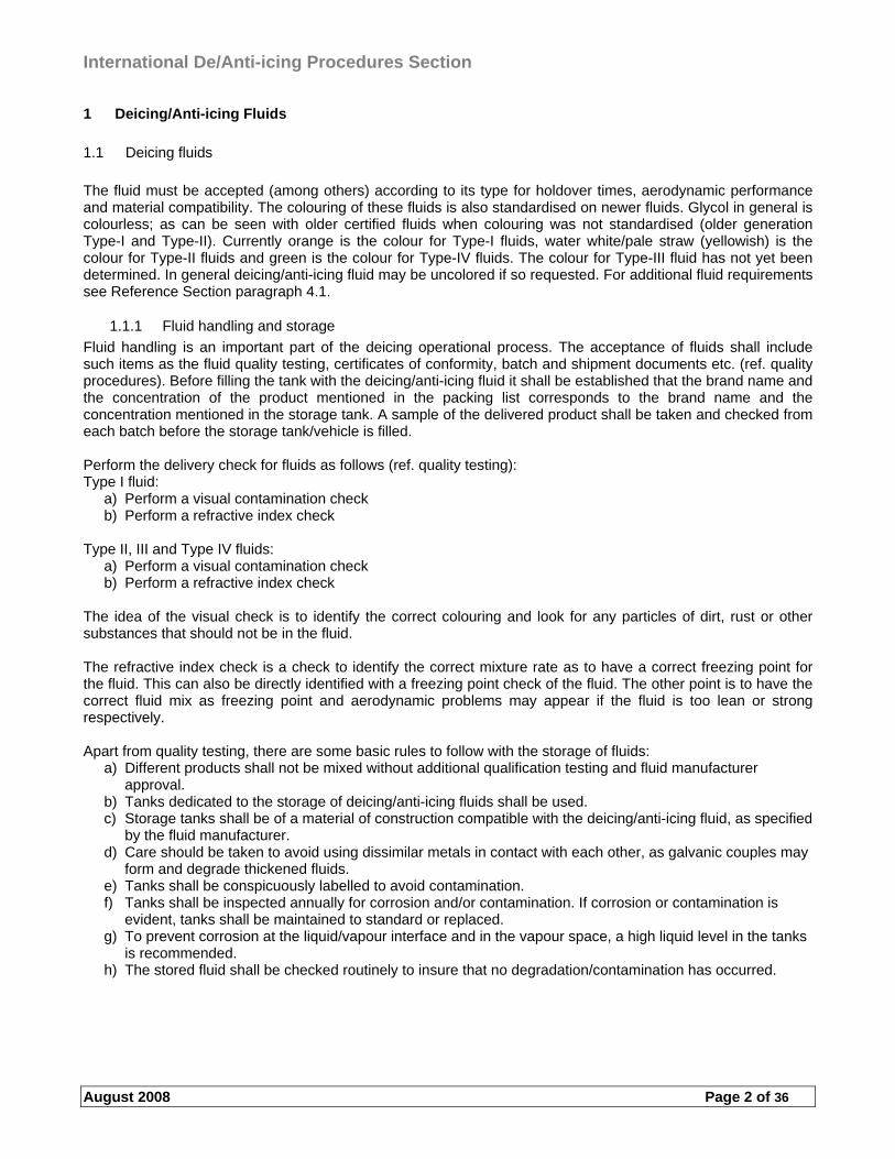
The fluid must be accepted (among others) according to its type for holdover times, aerodynamic performance and material compatibility. The colouring of these fluids is also standardised on newer fluids. Glycol in general is colourless; as can be seen with older certified fluids when colouring was not standardised (older generation Type-I and Type-II). Currently orange is the colour for Type-I fluids, water white/pale straw (yellowish) is the colour for Type-II fluids and green is the colour for Type-IV fluids. The colour for Type-III fluid has not yet been determined. In general deicing/anti-icing fluid may be uncolored if so requested. For additional fluid requirements see Reference Section paragraph 4.1.
1.1.1 Fluid handling and storage
Fluid handling is an important part of the deicing operational process. The acceptance of fluids shall include such items as the fluid quality testing, certificates of conformity, batch and shipment documents etc. (ref. quality procedures). Before filling the tank with the deicing/anti-icing fluid it shall be established that the brand name and the concentration of the product mentioned in the packing list corresponds to the brand name and the concentration mentioned in the storage tank. A sample of the delivered product shall be taken and checked from each batch before the storage tank/vehicle is filled. Perform the delivery check for fluids as follows (ref. quality testing): Type I fluid:
a) Perform a visual contamination check b) Perform a refractive index check
Type II, III and Type IV fluids:
a) Perform a visual contamination check b) Perform a refractive index check
The idea of the visual check is to identify the correct colouring and look for any particles of dirt, rust or other substances that should not be in the fluid. The refractive index check is a check to identify the correct mixture rate as to have a correct freezing point for the fluid. This can also be directly identified with a freezing point check of the fluid. The other point is to have the correct fluid mix as freezing point and aerodynamic problems may appear if the fluid is too lean or strong respectively. Apart from quality testing, there are some basic rules to follow with the storage of fluids:
a) Different products shall not be mixed without additional qualification testing and fluid manufacturer approval.
b) Tanks dedicated to the storage of deicing/anti-icing fluids shall be used. c) Storage tanks shall be of a material of construction compatible with the deicing/anti-icing fluid, as specified
by the fluid manufacturer. d) Care should be taken to avoid using dissimilar metals in contact with each other, as galvanic couples may
form and degrade thickened fluids. e) Tanks shall be conspicuously labelled to avoid contamination. f) Tanks shall be inspected annually for corrosion and/or contamination. If corrosion or contamination is
evident, tanks shall be maintained to standard or replaced. g) To prevent corrosion at the liquid/vapour interface and in the vapour space, a high liquid level in the tanks
is recommended. h) The stored fluid shall be checked routinely to insure that no degradation/contamination has occurred.
International De/Anti-icing Procedures Section
August 2008 Page 3 of 36
1.1.1.1 Pumping and heating
Deicing/anti-icing fluids can show degradation caused by excessive mechanical shearing. Therefore only compatible pumps and spraying nozzles shall be used. The design of the pumping systems shall be in accordance with the fluid manufacturer’s recommendations. Deicing/anti-icing fluids shall be heated according to the fluid manufacturer’s guidelines. For Type I fluids, water loss may cause undesirable aerodynamic effects. For Type II/III/IV fluids thermal exposure and/or water loss may cause a reduction in fluid viscosity leading to lower holdover times. The fluids shall be checked periodically. Caution must be taken to avoid unnecessary heating of fluid in vehicle tanks. Prolonged or repeated heating of fluids (directly or indirectly) may result in loss of water, which can lead to performance degradation of the fluid. Any of the following situations or a combination of them can accelerate the fluid performance degradation:
a) Low fluid consumption b) Trucks being in standby mode with heating system on for extended periods of time c) High temperatures in fluid tanks d) High temperatures in water tanks, which are in direct contact with the fluid tank (no insulation between
tanks).
1.1.1.2 Storage tanks
The storage of fluids can be done in a variety of ways, large stainless steel (acid-proof or plain steel) containers, 1 m3 containers, barrels etc. The storage procedure should be chosen according to the scope and amount of operation. Heating of the fluid in the storage tanks depends on the equipment in use. If the equipment heats the fluid before spraying then heating the fluid in the tanks may be unnecessary. The heating must fulfill any other requirements set for the fluid. Annual visual inspections of all tanks must be performed. Stainless steel (or acid-proof) tanks must be visually inspected annually (as other tanks) but a more in-depth inspection, such as non destructive testing (NDT) made for e.g. steel tanks, may not be necessary on an annual basis. The testing periods should be conducted according to the container manufacturer recommendations. Records must be kept for any and all inspections of tanks and station.
1.1.1.3 Field/periodical quality testing of fluids
The quality of fluids (visual check and refractive index check for Type-I, -II, -III and –IV) sprayed must be checked each time the equipment is in use and from each mixture of fluid used. This is to verify that the quality of the fluid, freezing point and mixture are correct. The refractive index test and the result must be conducted and compared according to given tables and instructions for each particular fluid. A temperature measurement should be conducted on a periodical basis in realistic conditions, relating to Type-I heating requirements, for verification of temperature in the tank (as a comparison vs. nozzle temperature if applicable) and at the nozzle. A sampling procedure for thickened fluids shall be performed according to a periodical system during the season (ref. quality and sampling procedures). If there are found any deviations outside the limits of the fluids, a corrective measure must be taken immediately to correct the fluid, equipment or procedures.
1.1.2 Laboratory Checks
The laboratory checks shall be performed for the fluids. The fluid samples shall be taken from all storage tanks and from all deicing/anti-icing vehicle nozzles. Samples shall be taken in all concentrations used for anti-icing (T-II/III/IV). Perform the laboratory check for fluids as follows: Type II, III and Type IV fluids:
a) Perform a visual contamination check b) Perform a refractive index check c) Perform a pH-value check d) Perform a laboratory viscosity check (for samples from anti-icing spray nozzle(s) and storage tank(s))
To ensure that the necessary safety margins are maintained between the start of the deicing/anti-icing operation and takeoff, the fluid used to both de-ice and anti-ice aircraft surfaces, must be in an ”ex-fluid manufacturers” condition and at the correct concentration. Due to the possible effect of vehicle/equipment heating and/or delivery system components on fluid condition, it is necessary for the sampling method to simulate typical aircraft application.
International De/Anti-icing Procedures Section
August 2008 Page 4 of 36
Select the required flow rate/spray pattern for the fluid to be sampled. Spray the fluid to purge the lines and check the concentration of a sample, taken from the gun/nozzle after purging. Direct the fluid onto the sampling surface and spray an adequate amount of fluid to allow for a sample to be taken. Attach a label to each sample, providing the following data:
a) Station name (and/or IATA code) b) Date sample was taken c) Handling company (and/or IATA code) d) Identification of deicing/anti-icing equipment/vehicle (e.g. Elephant Beta, Fixed Rig, etc.) e) Vehicle/Rig number (or tank/batch number if taken from station) f) Brand name and Type of the fluid (e.g. Kilfrost ABC-3/Type II, Clariant MPII 1951/Type II, etc.) h) Detail where the sample was taken from (e.g. nozzle, storage tank or equipment/vehicle tank) i) Mixture strength (e.g. 100/0, 75/25, etc.) j) Other information k) Sample taken by
The sampling procedure ensures that the required safety standards concerning the deicing/anti-icing fluid quality are maintained. Field check for fluids shall be made always when station inspection is made. The samples shall be taken from the storage tank and from the deicing/anti-icing equipment nozzle.
1.1.2.1 Fluid Check Methods
Visual Contamination Check a) Put fluid from the sample into a clean glass bottle or equivalent b) Check for any kind of contamination (e.g. rust particles, metallic debris, rubber parts, etc.) c) The check can be made by any equivalent method
Refractive Index Check
a) Make sure the refractometer is calibrated and clean b) Put a fluid drop taken from the sample or from the nozzle onto the test screen of the refractometer and
close the prism. Note that you should purge the line well before taking a sample for the refractive index check.
c) Read the value on internal scale and use the correction factor given by the manufacturer of the fluid in case the temperature of the refractometer is not 20ºC
d) Compare the value with the figures from the fluid manufacturer* e) Clean the refractometer and return it into the protective cover f) The check can be made by any equivalent method
*) If a fluid manufacturer has not published any tolerances for the refractive index of diluted fluids, the measured refractive index shall be within limits corresponding to a concentration not lower than the nominal concentration and not higher than 7% above the nominal concentration. For Type I fluids, the highest concentration at which a product may be used must also be observed. Example: For a sample with 50% nominal concentration, the measured refractive index must correspond to minimum 50% and maximum 57% concentration PH-value Check**
a) Take a piece of pH paper and put it in the fluid so that the pH paper becomes wetted with the fluid b) Remove the pH paper from the fluid and compare its colour with the colour of the table provided with the
pH paper and read the corresponding pH value c) Compare the pH-value with the figures from the fluid manufacturer d) The check can be made by any equivalent method e) pH check in the laboratory should be performed with a pH-measurement instrument
International De/Anti-icing Procedures Section
August 2008 Page 5 of 36
Field Viscosity Check a) This check shall be made with a falling ball method, where the reference liquids represent the minimum
and maximum allowed viscosity of the tested product b) Put the sample into a clean sample tube c) Fill the glass tube completely, insert the steel ball into the glass and close it d) Return the glass into the test tool and turn it vertically and let all steel balls reach the lower end of the test
tubes e) After all 3 balls have reached the bottom of the tubes, turn the tool ±180 degrees to a full vertical position f) The balls will move downwards with a different speed g) The speed of the middle steel ball shall be between the speed of the two other balls or be equal to the
speed of one of them h) The check can be made by any equivalent method
Laboratory Viscosity Check
a) Perform the viscosity check in accordance with AIR 9968 b) The measurements shall be carried out at rotation speeds of 0.3 rpm c) The temperatures at which the measurements are made and the spindle number shall be reported d) Compare the viscosity values with figures from fluid manufacturer e) The check can be made by any equivalent method f) Relevant test procedure documents shall be used, e.g. SAE AIR 9968
Deicing/Anti-icing Vehicle Fluid Checks (Concentration Check).
a) Fluids or fluid/water mixture samples shall be taken from the deicing/anti-icing vehicle nozzles on a daily basis when vehicles are in use. Perform a refractive index check according to given procedures. The sample shall also be protected against precipitation.
b) Samples may be taken from the truck tank instead of at the nozzle from trucks filled with “premixed” or undiluted fluids.
c) Operational setting for flow and pressure shall be used for trucks with proportional mixing systems. Allow the selected fluid concentration to stabilise before taking sample.
d) The interval for refractive index checks has to be determined by the handling company in accordance with the system design for trucks with automated fluid mixture monitoring system.
Checks on (directly or indirectly) heated Fluids a) Fluid or fluid/water mixture samples shall be taken from the deicing/anti-icing vehicle tanks. As a
guideline, the interval should not exceed two weeks, but it may be adjusted in accordance with local experience.
b) Perform a Refractive Index Check **) Perform this check if it is suitable to identify contaminants in the fluid and/or detect degradation of the fluid used. The idea of the visual check is to identify the correct colouring and look for any particles of dirt, rust or other substances that should not be in the fluid. It is also a good indication to note the colour of the mixture if it looks as lean or strong as the selected mixture rate should approximately be. The refractive index check is a check to identify the correct mixture rate as to have a correct freezing point for the fluid. This can also be directly identified with a freezing point check of the fluid. The other point is to have the correct fluid mix as freezing point and aerodynamic problems may appear if the fluid is too lean or strong respectively. The pH-check only identifies if the fluid is a neutral fluid as glycol should be. As this is very difficult to identify precisely with pH-paper a laboratory test sample may be more representative. This is not always possible to do in a laboratory and the main point is to identify that the fluid is not contaminated with e.g. an acid or alkaline substance that may change the correct performance of the fluid when mixed with the glycol in great amounts. Another possibility is to identify aircraft glycol from runway glycol when they are not coloured. This can be noted with visibly different pH-values, even with a paper test.
International De/Anti-icing Procedures Section
August 2008 Page 6 of 36
Concentration checks identify that the vehicle mixing system is functioning properly and that the fluid at nozzle is what has been selected. Note that the lines may have different mixtures of fluid or even water so the fluid at the nozzle can be something else than selected if not purging the lines properly. It si sufficient to take a vehicle tank sample for pre-mix fluids. Checking heated fluids in the storage tanks and vehicle tanks when they have been unused and heated for a long time identifies that the water content is correct in the water/glycol mixture (no evaporation).
International De/Anti-icing Procedures Section
August 2008 Page 7 of 36
DEICING/ANTI-ICING OPERATIONS
1.2 General
The deicing/anti-icing operation must be suited for each airport, company and local setting. However, airworthiness and operational regulations state that no one can take-off in an aircraft that has any contamination on critical surfaces. Even if the procedure of deicing the aircraft varies, all critical surfaces shall be clean. Anti-icing the aircraft sets its own requirements of fluid to be used. Mechanical ways cannot be seen as an anti-icing procedure, the surfaces shall be protected from refreezing. Only certified fluids and accepted procedures are to be used. The clean aircraft concept shall be set as the only way of operating.
1.3 Preliminary work for the start of deicing/anti-icing
Before the deicing operation can begin, inspect the equipment. This inspection should include all relevant aspects for the proper functioning of the equipment, personal gear and the fluids (see DEVA Checklist). A verification of procedures for deicing/anti-icing should then be made. Procedures may vary according to local demands. The necessary inspections and communications can be made beforehand at the gate whereas at remote/centralised deicing, necessary information must be informed to the deicing crew in another way (e.g. coordinator communication). The determining of the need for deicing/anti-icing can be made by other qualified persons, not necessary the deicing crew. Pilots must have a description on any local differences they will be exposed to (e.g., de-ice/anti-ice location, fluids and mixtures available, start clearance for deicing, checks, etc.). In some cases, required paperwork/data of the deicing operation can be recorded beforehand to speed up the process.
1.3.1 Determining the need for deicing/anti-icing
The need for deicing/anti-icing is usually determined well beforehand by the trained and qualified ground crew or flight crew. Certain aspects must be considered, such as, what are the A/C specific requirements and precautions, is the deicing operation performed at gate or remote, can the aircraft start the engines and taxi to a remote deicing fully contaminated, who makes the request for the deicing, verification of proper procedure with all parties involved (ground crew / flight crew / deicing), should air-blower/brushes be used beforehand etc. The contamination check shall cover all critical parts of the aircraft and shall be performed from points offering sufficient visibility of these parts (e.g. from the deicing vehicle itself or any other suitable piece of equipment). Any contamination found, except frost allowed in certain areas, shall be removed by a deicing treatment followed by an anti-icing treatment if required. Some inspected areas can be cleaned manually during the inspection and a deicing procedure is not necessary. This procedure must be confirmed with the flight crew. The captain has the final authority of the procedure but the safer option should always be considered, whether it is the opinion of the flight crew or ground crew (company and A/C limits to be noted). There are some areas to include in the inspection while waiting for instructions from the flight crew. Areas to check include: a) Wings (upper and lower) b) Vertical and horizontal tail surfaces (upper and lower horizontal surfaces) c) Fuselage d) Engine inlets and fan blades (front and back side of fan blades) e) Control surfaces and gaps f) Pitot heads and static ports g) Landing gear and landing gear doors h) Antennas and sensors i) All other aerodynamic surfaces j) Propellers After checking these areas, a decision with the flight crew of deicing procedures can be made accordingly. The weather elements and taxi distances will affect the choice for type and mixture of fluid to use.
International De/Anti-icing Procedures Section
August 2008 Page 8 of 36
1.3.1.1 One-step/two-step deicing/anti-icing
When aircraft surfaces are contaminated by frozen moisture, they shall be de-iced prior to dispatch. When freezing precipitation exists and there is a risk of contamination of the surface at the time of dispatch, aircraft surfaces shall be anti-iced. If both deicing and anti-icing are required, the procedure may be performed in one or two steps. The selection of a one- or two-step process depends upon weather conditions, available equipment, available fluids and the holdover time to be achieved. Some contamination, such as frost, can be removed and the surface protected from refreezing, all at the same time using the same fluid and same mixture. This is called a one-step procedure. One-step deicing/anti-icing is generally performed with a heated unthickened fluid. Thickened fluid can and is in some cases used for this one-step process. Caution must be taken for the dry-out characteristics and gel residue problems of this particular scenario.The mixture to choose for this step is the mixture that gives a protective cover; in other words, the deicing is performed with an anti-icing mixture, which protects the surface at the same time. The correct fluid concentration shall be chosen with regard to desired holdover time and is dictated by outside air temperature and weather conditions. Wing skin temperatures may differ and, in some cases, be lower than OAT. A stronger mix (more glycol in the glycol-water mixture) can be used under these conditions. The stronger mix will not improve the holdover time but it will lower the freezing point of the mixture. Two-step deicing/anti-icing (when the first step is performed with deicing fluid) is a procedure performed whenever the contamination demands a deicing process separately. The correct fluid(s) shall be chosen with regard to ambient temperature. After deicing, a separate over-spray of anti-icing fluid shall be applied to protect the relevant surfaces thus providing maximum possible anti-ice capability. The second step is performed with anti-icing fluid. The correct fluid concentration shall be chosen with regard to desired holdover time and is dictated by outside air temperature and weather conditions. The second step shall be performed before first step fluid freezes (typically within 3 min), if necessary area by area. A two step procedure is common during freezing precipitation. The second step shall be applied in such a way that it gives a complete, sufficient and an even layer of anti-icing fluid on the treated surfaces.
1.3.2 Critical surfaces
Basically all surfaces that have an aerodynamic-, control-, sensing-, movement- or measuring-function must be clean. All of these surfaces can not necessarily be cleaned and protected in the same conventional deicing/anti-icing manner as e.g. the wings. Some areas require only a cleaning operation while other need protection against freezing. The procedure of deicing may also vary according to A/C limitations. The use of hot air may be required when deicing e.g. landing gear or propellers. Some critical elements and procedures to follow, common for most aircraft is:
a) Deicing/anti-icing fluids shall not be sprayed directly on wiring harnesses and electrical components (receptacles, junction boxes, etc.), onto brakes, wheels, exhausts, or thrust reversers.
b) Deicing/anti-icing fluid shall not be directed into the orifices of pitot heads, static ports or directly onto airstream direction detectors probes/angle of attack airflow sensors.
c) All reasonable precautions shall be taken to minimise fluid entry into engines, other intakes/outlets and control surface cavities.
d) Fluids shall not be directed onto flight deck or cabin windows as this can cause crazing of acrylics or penetration of the window seals.
e) Any forward area from which fluid can blow back onto windscreens during taxi or subsequent takeoff shall be free of residues prior to departure.
f) If Type II, III or Type IV fluids are used, all traces of the fluid on flight deck windows should be removed prior to departure, particular attention being paid to windows fitted with wipers.
g) Landing gear and wheel bays shall be kept free from build-up of slush, ice or accumulations of blown snow.
h) When removing ice, snow, slush or frost from aircraft surfaces care shall be taken to prevent it entering and accumulating in auxiliary intakes or control surface hinge areas, e.g. manually remove snow from wings and stabilizer surfaces forward towards the leading edge and remove from ailerons and elevators back towards the trailing edge.
International De/Anti-icing Procedures Section
August 2008 Page 9 of 36
1.3.2.1 Clean aircraft concept
The clean aircraft concept must be understood as an important part for the safety of the flight. A clean aircraft is considered to be either totally clean or cleaned and protected with deicing/anti-icing fluids that still protect the surface and are able to perform aerodynamically correct. Contaminated fluid on the surface must not be misunderstood as a clean aircraft; this contamination must be removed. Under no circumstances shall an aircraft that has been anti-iced receive a further coating of anti-icing fluid directly on top of the contaminated film. If an additional treatment is required before flight, a complete deicing/anti-icing shall be performed. Ensure that any residues from previous treatment are flushed off. Anti-icing only is not permitted.
1.4 Spray areas
Areas to spray on any aircraft are in most cases the upper surfaces. However, underwing deicing may for some A/C types be very common. When talking about upper surfaces, it is referred to as the wings, tail (including vertical stabilizer) and fuselage. As a rule of thumb, the deicing/anti-icing procedure should be performed from the top-down, leading edge towards trailing edge and from the A/C front parts backwards. On most aircraft start at the wing tip and work towards the wing root. Areas to protect from refreezing depend on the aircraft limitations but in general the upper surfaces of the wings and the tail section should be anti-iced. The fuselage may also need anti-icing but underwings are not generally anti-iced with thickened fluid.
1.4.1 Aircraft surfaces
There is no single rule of spray order that can be applied to all aircraft. It is, however, recommended to start with the fuselage (front part covering the wing area) whenever it needs treatment (spray along the top centre-line and then outboard). After the fuselage comes the wings and the way to treat the wings depends on the aircraft and the place where deicing is performed (gate vs. remote). The wing should always be treated from the highest part towards the lowest part (generally wingtip inboard). Some aircraft have the wingtips lower than the wingroot and in that case deicing should be performed from the wingroot outboard. The tail should be performed from the vertical stabilizer downward and the aft-fuselage part before the horizontal stabilizer (excluding T-tail A/C). It is recommended that anti-icing fluid be sprayed within 3 min. after deicing but in no case can it be sprayed after the deicing fluid freezes. If the wing area is large and the contamination is heavy, previously de-iced parts should be considered to be de-iced again before anti-icing. The following surfaces shall be protected:
a) Wing upper surface and leading edges b) Horizontal stabilizer upper surfaces including leading edges and elevator upper surfaces c) Vertical stabilizer and rudder d) Fuselage upper surfaces including VHF-antenna depending upon the amount and type of precipitation
(required on centre-line engine aircraft). Underwings do not need anti-icing since the precipitation cannot reach there. However, a sufficiently high (concentrated) mixture must be used so as not to cause ice formation after the deicing. Gate deicing is somewhat different than remote/centralised deicing and local settings and precautions should be noted. Using multiple deicing vehicles at one aircraft may change the spray order but the same concept (high-low, front-back) should be applied. Different vehicles may also be needed for different deicing work (e.g. underwing) in this case the procedure should be coordinated accordingly.
1.4.1.1 Other areas
Other areas on the aircraft may need special attention or procedures to clean. Windows (flightdeck windows) need deicing but there is no need for anti-icing. It should be noted that drain off water may freeze elsewhere on the fuselage if using water for deicing flightdeck windows, there is otherwise no limitation on using water on windows than freezing. The radome needs deicing. Caution must be taken so that fluids would not flow in large quantities on the flightdeck windows during takeoff (if the radome has been treated). Static ports and pitot tubes may need inspection. Any contamination like, e.g. ice and drain off fluid, shall be removed from these areas. The repeated application of Type II, III or IV fluid may cause residues to collect in aerodynamically quiet areas, cavities and gaps. The Application of hot water or heated Type I fluid in the first step of the deicing/anti-icing process may minimise the formation of residues. Residues may re-hydrate and freeze under certain temperature, high humidity and/or rain conditions and may block or impede critical flight control systems. These residues may require removal. When checking for residues, misting with water may facilitate their visibility. It
International De/Anti-icing Procedures Section
August 2008 Page 10 of 36
must be clear that deicing or anti-icing should not be performed (sprayed) from the trailing edge forward. This can cause even more residue to collect and there is also the danger of removing grease from hinges and other parts. Engine inlets and fan blades need deicing in some cases. Inlets can generally be cleaned with a brush or manually by hand. Fan blades and the bottom of the engine air inlet needs to be de-iced with hot air, or other means recommended by the engine manufacturer. No deicing fluid is to be sprayed directly into engines. Propellers may have ice along the leading edges and/or may collect snow/slush along the side during a ground stop. This contamination can be removed manually with a soft cloth or by hand. Some manufacturers allow the propellers to be sprayed but some forbid the use of glycol. Hot air, or other means recommended by the engine manufacturer, can be used for deicing propellers (composite propellers have temperature limits that must be noted). The application of deicing fluid in landing gear and wheel bay areas shall be kept to a minimum. Deicing fluid shall not be sprayed directly onto brakes and wheels. Accumulations such as blown snow may be removed by other means than fluid (mechanically, air blast, heat etc). However, where deposits have bonded to surfaces, they can be removed by the application of hot air or by spraying with hot deicing fluids by using a low-pressure spray.
1.4.2 Spray methods, fluid application and alternate methods
Choosing a correct spray method may vary as much as the winter weather does. The procedure must be adapted according to the situation and local settings. Ice, snow, slush or frost may be removed from aircraft surfaces by heated fluids, mechanical methods, alternate technologies or combinations thereof. For maximum effect, fluids shall be applied close to the surface of the skin to minimise heat loss but equipment must remain at a safe distance to avoid aircraft damage. The heat in the fluid effectively melts any frost, as well as light deposits of snow, slush/sleet and ice. Heavier accumulations require the heat to break the bond between the frozen deposits and the structure; the hydraulic force of the fluid spray is then used to flush off the residue.
1.4.2.1 Removal of contamination
When removing frost a nozzle setting giving a solid cone (fan) spray should be used. This ensures the largest droplet pattern available, thus retaining the maximum heat in the fluid. Providing the hot fluid is applied close to the aircraft skin, a minimal amount of fluid will be required to melt the deposit. When removing snow a nozzle setting sufficient to flush off deposits and minimise foam production is recommended. Note that foam could be confused as snow. The procedure adopted will depend on the equipment available and the depth and type of snow (e.g. light and dry or wet and heavy). In general, the heavier the deposits the heavier the fluid flow that will be required to remove snow effectively and efficiently from the aircraft surfaces. For light deposits of both wet and dry snow, similar procedures as for frost removal may be adopted. Wet snow is more difficult to remove than dry snow and unless deposits are relatively light, selection of high fluid flow will be found to be more effective. Under certain conditions it will be possible to use the heat, combined with the hydraulic force of the fluid spray to melt and subsequently flush off frozen deposits. Heavy accumulation of snow will always be difficult to remove from aircraft surfaces and vast quantities of fluid will invariably be consumed in the attempt. Under these conditions, serious consideration should be given to removing the worst of the snow manually before attempting a normal deicing procedure. Heated fluid is very important when removing ice as well as the pressure of the spray to break the ice bond. The method makes use of the high thermal conductivity of the metal skin. A stream of hot fluid is directed at safe close range onto one spot at an angle of less than 90, until the aircraft skin is exposed. The aircraft skin will then transmit the heat laterally in all directions raising the temperature above the freezing point thereby breaking the adhesion of the frozen mass to the aircraft surface. By repeating this procedure a number of times, the adhesion of a large area of frozen snow or glazed ice can be broken. The deposits can then be flushed off with either a low or high flow, depending on the amount of the deposit.
International De/Anti-icing Procedures Section
August 2008 Page 11 of 36
1.4.2.2 General fluid application strategy.
For effective removal and protection of snow and ice, the following techniques shall be adopted. Certain aircraft can require unique procedures to accommodate design differences, see manufacturers instructions. When choosing a mixture and spraying method, note that ice, snow or frost dilutes the fluid. Apply enough hot deicing fluid to ensure that re-freezing does not occur and all contaminated fluid is driven off. Symmetrical treatment is essential. Anti-icing fluid shall be applied to the aircraft surfaces (assuming that they are clean) if anticipated that precipitation may appear and adhere to the aircraft at the time of aircraft dispatch. Anti-icing fluid may be applied to aircraft surfaces at the time of arrival on short turnarounds during freezing precipitation and on overnight parked aircraft. This will minimise ice accumulation prior to departure and often makes subsequent deicing easier. This procedure has a potential risk of building residues and is not recommended if performed continuously. On receipt of a frost, snow, freezing drizzle, freezing rain or freezing fog warning from the local meteorological service, anti-icing fluid may be applied to clean aircraft surfaces prior to the start of freezing precipitation. This will minimise the possibility of snow and ice bonding or reduce the accumulation of frozen precipitation on aircraft surfaces and facilitate subsequent deicing. The time-factor must be taken into account when proceeding with these procedures (e.g. turn-arounds and short stops in general may be worthwhile but overnight stops should be thought out well). For effective anti-icing, an even layer of sufficient thickness of fluid is required over the prescribed aircraft surfaces, which are clean (free of frozen deposits). For longer anti-icing protection, undiluted, unheated Type II, III or Type IV fluid should be used. The high fluid pressures and flow rates normally associated with deicing are not allowed for this operation and, where possible, pump speeds should be reduced accordingly. The nozzle of the spray gun should be adjusted to provide a medium spray. The process should be continuous and as short as possible. Anti-icing should be carried out as near to the departure time as operationally possible in order to utilise maximum holdover time. The anti-icing fluid shall be distributed uniformly over all surfaces to which it is applied. In order to control the uniformity, all horizontal aircraft surfaces shall be visually checked during application of the fluid. Anti-icing fluids may not flow evenly over wing leading edges, horizontal and vertical stabilizers. These surfaces should be checked to ensure that they are properly coated with fluid. When applying the second step fluid, use a spraying technique, which completely covers the first step fluid and provides a sufficient amount of second step fluid. Where re-freezing occurs following the initial treatment, both first and second step shall be repeated. With regard to holdover time provided by the applied fluid, the objective is that it be equal to or greater than the estimated time from start of anti-icing to start of takeoff based on existing weather conditions. Aircraft shall be treated symmetrically, that is, left-hand and right-hand side shall receive the same and complete treatment when anti-icing. Deicing only may be local but still symmetrical. Aerodynamic problems could result if this requirement is not met. During anti-icing and deicing, the moveable surfaces shall be in a position as specified by the aircraft manufacturer.
International De/Anti-icing Procedures Section
August 2008 Page 12 of 36
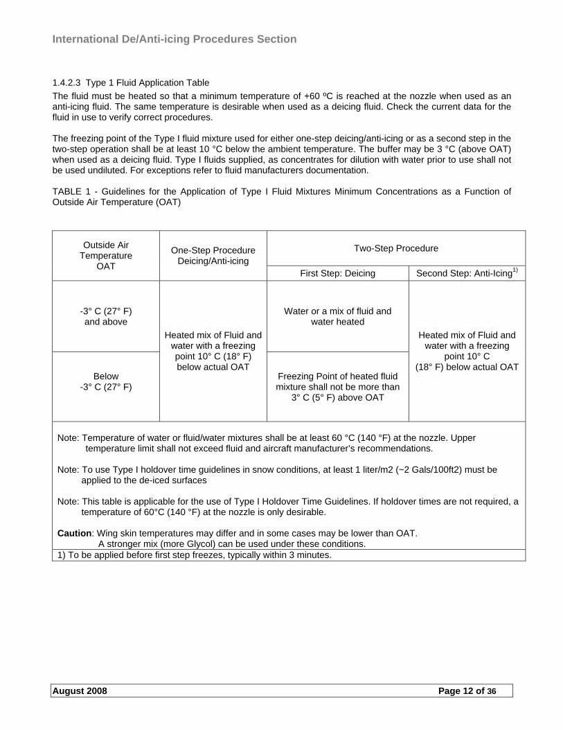
1.4.2.3 Type 1 Fluid Application Table
The fluid must be heated so that a minimum temperature of +60 ºC is reached at the nozzle when used as an anti-icing fluid. The same temperature is desirable when used as a deicing fluid. Check the current data for the fluid in use to verify correct procedures. The freezing point of the Type I fluid mixture used for either one-step deicing/anti-icing or as a second step in the two-step operation shall be at least 10 °C below the ambient temperature. The buffer may be 3 °C (above OAT) when used as a deicing fluid. Type I fluids supplied, as concentrates for dilution with water prior to use shall not be used undiluted. For exceptions refer to fluid manufacturers documentation. TABLE 1 - Guidelines for the Application of Type I Fluid Mixtures Minimum Concentrations as a Function of Outside Air Temperature (OAT)
Two-Step Procedure Outside Air Temperature
OAT
One-Step Procedure Deicing/Anti-icing
First Step: Deicing Second Step: Anti-Icing1)
-3° C (27° F) and above
Water or a mix of fluid and water heated
Below -3° C (27° F)
Heated mix of Fluid and water with a freezing point 10° C (18° F) below actual OAT
Freezing Point of heated fluid mixture shall not be more than
3° C (5° F) above OAT
Heated mix of Fluid and water with a freezing
point 10° C (18° F) below actual OAT
Note: Temperature of water or fluid/water mixtures shall be at least 60 °C (140 °F) at the nozzle. Upper
temperature limit shall not exceed fluid and aircraft manufacturer’s recommendations. Note: To use Type I holdover time guidelines in snow conditions, at least 1 liter/m2 (~2 Gals/100ft2) must be
applied to the de-iced surfaces Note: This table is applicable for the use of Type I Holdover Time Guidelines. If holdover times are not required, a
temperature of 60°C (140 °F) at the nozzle is only desirable. Caution: Wing skin temperatures may differ and in some cases may be lower than OAT. A stronger mix (more Glycol) can be used under these conditions. 1) To be applied before first step freezes, typically within 3 minutes.
International De/Anti-icing Procedures Section
August 2008 Page 13 of 36
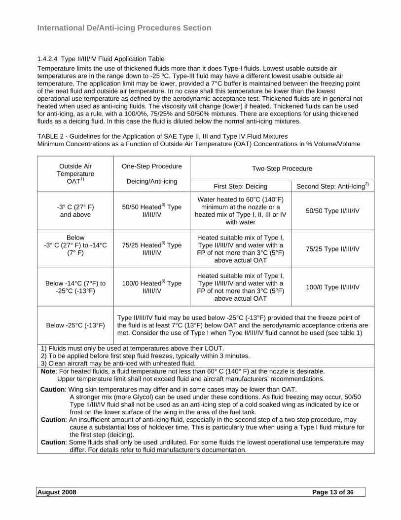
1.4.2.4 Type II/III/IV Fluid Application Table
Temperature limits the use of thickened fluids more than it does Type-I fluids. Lowest usable outside air temperatures are in the range down to -25 ºC. Type-III fluid may have a different lowest usable outside air temperature. The application limit may be lower, provided a 7°C buffer is maintained between the freezing point of the neat fluid and outside air temperature. In no case shall this temperature be lower than the lowest operational use temperature as defined by the aerodynamic acceptance test. Thickened fluids are in general not heated when used as anti-icing fluids. The viscosity will change (lower) if heated. Thickened fluids can be used for anti-icing, as a rule, with a 100/0%, 75/25% and 50/50% mixtures. There are exceptions for using thickened fluids as a deicing fluid. In this case the fluid is diluted below the normal anti-icing mixtures. TABLE 2 - Guidelines for the Application of SAE Type II, III and Type IV Fluid Mixtures Minimum Concentrations as a Function of Outside Air Temperature (OAT) Concentrations in % Volume/Volume
Two-Step Procedure Outside Air Temperature
OAT1)
One-Step Procedure
Deicing/Anti-icing First Step: Deicing Second Step: Anti-Icing2)
-3° C (27° F) and above
50/50 Heated3) Type II/III/IV
Water heated to 60”C (140”F) minimum at the nozzle or a
heated mix of Type I, II, III or IV with water
50/50 Type II/III/IV
Below -3° C (27° F) to -14°C
(7° F)
75/25 Heated3) Type II/III/IV
Heated suitable mix of Type I, Type II/III/IV and water with a FP of not more than 3°C (5°F)
above actual OAT
75/25 Type II/III/IV
Below -14°C (7°F) to -25°C (-13°F)
100/0 Heated3) Type II/III/IV
Heated suitable mix of Type I, Type II/III/IV and water with a FP of not more than 3°C (5°F)
above actual OAT
100/0 Type II/III/IV
Below -25°C (-13°F) Type II/III/IV fluid may be used below -25°C (-13°F) provided that the freeze point of the fluid is at least 7°C (13°F) below OAT and the aerodynamic acceptance criteria are met. Consider the use of Type I when Type II/III/IV fluid cannot be used (see table 1)
1) Fluids must only be used at temperatures above their LOUT. 2) To be applied before first step fluid freezes, typically within 3 minutes. 3) Clean aircraft may be anti-iced with unheated fluid. Note: For heated fluids, a fluid temperature not less than 60° C (140° F) at the nozzle is desirable. Upper temperature limit shall not exceed fluid and aircraft manufacturers’ recommendations.
Caution: Wing skin temperatures may differ and in some cases may be lower than OAT. A stronger mix (more Glycol) can be used under these conditions. As fluid freezing may occur, 50/50 Type II/III/IV fluid shall not be used as an anti-icing step of a cold soaked wing as indicated by ice or frost on the lower surface of the wing in the area of the fuel tank.
Caution: An insufficient amount of anti-icing fluid, especially in the second step of a two step procedure, may cause a substantial loss of holdover time. This is particularly true when using a Type I fluid mixture for the first step (deicing).
Caution: Some fluids shall only be used undiluted. For some fluids the lowest operational use temperature may differ. For details refer to fluid manufacturer's documentation.
International De/Anti-icing Procedures Section
August 2008 Page 14 of 36
1.4.2.5 Alternate methods
Alternate technology may be used to accomplish the deicing process, provided that the requirements are accomplished. Such procedures may be brooms/brushes, air blowers, infrared technology etc. Mechanical methods may be helpful for removing contamination but it shall not be considered clean and protected as to deicing/anti-icing. Aircraft manufacturer requirements and airline limitations shall be noted when using infrared technology for deicing. Brushes and air is useful when deicing areas where fluid application is limited or forbidden. The flight crew shall always be notified of the procedure used and to be consulted for further actions.
1.4.2.5.1 Infrared Deicing Facility
This sub-section establishes the procedures for removal of frozen precipitation by using infrared deicing technology.
1.4.2.5.1.1 General Requirements: Ice, slush, snow, and frost shall be removed from aircraft surfaces prior to dispatch from the facility or prior to anti-icing.Deicing:
1.4.2.5.1.2 Deicing using infrared energy is accomplished through heat that breaks the bond of adhering frozen contamination. The application of infrared energy may be continued to melt and evaporate frozen contaminants. Wet surfaces require an application of heated deicing fluids to preclude refreezing after removal of infrared energy source. When required, for operations other than frost or leading edge ice removal and when OAT is at or below 0°C (32°F), an additional treatment with hot deicing fluid shall be performed within the facility to prevent re-freezing of water which may remain in hidden areas.
CAUTION: If the aircraft requires re-deicing and de/anti-icing fluids had been applied before flight, conventional
de/anti-icing with fluids shall be performed.
1.4.2.5.1.3 Anti-icing: If anti-icing is required, it shall be accomplished in accordance with this section. If anti-icing is performed inside the facility, infrared power levels must be adjusted as required during the anti-icing process to prevent the re-accumulation of frozen contamination due to the effect of blowing snow through the facility and maintain fluid integrity for the time the aircraft is in the facility. Dehydration of the fluid can negatively impact the fluid performance.
1.4.3 Inspecting sprayed areas
A verification of clean surfaces (regarding contamination) shall always be made after the deicing/anti-icing. This verification can be either visual or tactile (depending on aircraft limitations/requirements). Note that any visual check may not be sufficient in certain situations (like clear ice). A tactile check (hands-on) is the best choice whenever there is a doubt. There are technology available (cameras/Ground Ice Detection Systems) for checking the surfaces but this must be approved both locally and by the FAA. Some aircraft require a hands on check to verify the surface is clean. These inspections should be made both before and after deicing/anti-icing. Note that a trained and qualified person shall not dispatch an aircraft after a deicing/anti-icing operation until the aircraft has received a final check. If the check is not to be performed by the flight crew then the commander must ensure that he has received confirmation that it has been accomplished before take off. Inspections should visually cover all critical parts of the aircraft and be performed from points offering sufficient visibility of these parts (e.g. from the de-icer itself or another elevated piece of equipment). Any contamination found, shall be removed by further deicing/anti-icing treatment and the check repeated. If a pre-deicing/anti-icing procedure or a local frost prevention procedure has been performed a tactile check (by touch) of the treated areas and a visual check of the untreated areas of both wings shall be performed immediately before the aircraft leaves the parking position. These checks are conducted to insure that both wings are clean and free of frost and ice. The applied deicing/anti-icing fluid shall still be liquid and shall show no indication of failure, such as colour turning to white, loss of gloss, getting viscous, showing ice crystals etc. The Anti-Icing Code shall not be transmitted before the post deicing/anti-icing check is completed.
International De/Anti-icing Procedures Section
August 2008 Page 15 of 36
1.4.3.1 Clear ice checks and precautions
Clear ice can form on aircraft surfaces, below a layer of snow or slush/sleet. It is therefore important that surfaces are closely examined following each deicing operation, in order to ensure that all deposits have been removed. Significant deposits of clear ice can form, in the vicinity of the fuel tanks, on wing upper surfaces as well as under-wing. This type of ice formation is extremely difficult to detect. Therefore when the conditions prevail, or when there is otherwise any doubt whether clear ice has formed, a close examination shall be made immediately prior to departure, in order to ensure that all frozen deposits have in fact been removed. Note that this type of build-up normally occurs at low wing temperatures and when large quantities of cold fuel remain in wing tanks during the turnaround/transit and any subsequent re-fuelling is insufficient to cause a significant increase in fuel temperature. This does not rule out the possibility of ice formation in any other conditions. Finding clear ice, and removing it, should always be noted to the flight crew. Frost on the underside and humidity (or precipitation) is a good sign that there may be clear ice forming on the upper surfaces, but note that this is not the single way to determine ice formation.
1.5 Deicing/anti-icing communication
Proper communication is as important as proper deicing/anti-icing. There cannot be any doubt of the procedure, fluid used, holdover time, areas covered etc. when communicating and verifying the process. As a rule, an aircraft shall not be dispatched for departure after a deicing/anti-icing operation until the flight crew has been notified of the type of deicing/anti-icing operation performed. The standardised notification performed by qualified personnel indicates that the aircraft critical parts are checked free of ice, frost, snow, and slush, and in addition includes the necessary anti-icing code, as specified, to allow the flight crew to estimate the holdover time to be expected under the prevailing weather conditions. The person communicating with the flight crew shall have a basic knowledge of the English language in order to communicate properly (refer to Annex D, ICAO language levels, operational level 4 is the preferred minimum). As important as the communication between the flight crew and the deicing crew so is the communication between the deicing crews themselves and the deicing coordinator. No misconception can be allowed when deciding on treatment and verifying operational procedures. If several deicing vehicles are performing the deicing/anti-icing simultaneously on an aircraft, a lead vehicle/person should be decided. This team leader will be the person communicating with the aircraft and the vehicles at the aircraft. The procedures and the areas to be treated are divided and settled according to the team leader instructions. This procedure will increase the safety of proper communication and operations. The team leader will give instructions on fluids and mixtures to use, areas to be treated and by whom etc. After the procedure is done, all vehicles report to the team leader their particular information.. The team leader will conclude which area was treated first with anti-icing fluid and report this time to the flight crew along with the rest of the required information (anti-icing code). At the time of final report, all vehicles shall be in a safety area or in a position well clear of the aircraft. The procedure should reflect the local demands.
1.5.1 Releasing/Dispatching aircraft and final walk-around
The person releasing/dispatching the aircraft immediately before taxi and takeoff shall verify to the flight crew all relevant information regarding the deicing/anti-icing and/or clean surfaces. This person can also verify the deicing/anti-icing process and communicate on any relevant issues. Any other verification or check should be made at this point. The release person can perform the deicing/anti-icing code and other information if the deicing crew is unable to communicate with the flight crew.
International De/Anti-icing Procedures Section
August 2008 Page 16 of 36
1.5.1.1 The anti-icing code
The final communication with the flight crew is the anti-icing code. This information is very important for the flight crew when deciding on elements related to takeoff procedures. The following information shall be recorded and be communicated to the flight crew by referring to the last step of the procedure provided below:
a) The fluid type (e.g. Type I, II, III, IV) b) The concentration of fluid within the fluid/water mixture, expressed as a percentage by volume. Note that
this is no requirement for Type I fluid c) The local time (hours/minutes) at the beginning of the final deicing/anti-icing step d) The date (written: day, month, and year). Note that this is only required for record keeping, optional for
crew notification. e) The complete name of the anti-icing fluid (so called “brand name”). Note that the name is optional and for
Type II, III and IV fluids only. f) The statement "Post deicing/anti-icing check complete" (Optional). Transmission of elements A-C to the
flight crew confirms that a post deicing/anti-icing check, including tactile checks when applicable for all hard wing aircraft was completed and the aircraft’s critical surfaces are free of ice, snow, or frost.
If two different companies are involved in the deicing/anti-icing treatment and post deicing/anti-icing check, it shall be ensured that the anti-Icing code is not given before the post deicing/anti-icing check is completed. As an example, a deicing/anti-icing procedure which last step is the use of a mixture of 75% of a Type II fluid and 25% water, commencing at 13:35 local time on 20 February 2006, is recorded as follows: TYPE II/75 13:35 (20 FEB 2006) (“complete name of anti-icing fluid”). Post deicing/anti-icing check complete. The anti-icing code contains the minimum information needed for communication. It is allowed, and preferred, to give other information, such as areas treated, areas checked, engines and propellers, frost thickness on underwings etc, if there is a need for it or if the crew has requested something else. The way of communicating can vary with local settings and arrangements. There can be a VHF-, UHF-, headset/intercom at the A/C, team leader communication, and deicing vehicle or coordinator communication with the aircraft. The way of providing the information is not relevant, it is, however, important what and how communication is performed. Gate deicing and remote deicing can contain different communication needs.
1.5.2 Flight crew information
The flight crew shall be notified, and approve, of both the start and the finish of the deicing/anti-icing procedures. The aircraft needs to be configured before the start of the deicing/anti-icing and the crew must consider when they are able to depart before allowing the deicing operation to begin. Some aircraft need to shut of the APU, air-conditioning and some need to be informed of the deicing at certain parts of the aircraft (e.g. when deicing the tail) before the operation can begin. The main idea is to receive the “go-ahead” from the flight crew, they will then take into account any possible procedures needed. The flight crew shall receive a confirmation from the ground crew that all deicing/anti-icing operations are complete and that all personnel and equipment are clear before reconfiguring or moving the aircraft. The flight crew shall also be notified of any deicing/anti-icing procedures made beforehand (e.g. at night) or if preventive anti-icing has been performed. The pre-deicing/anti-icing does not rule out the need for an inspection or the need for an additional treatment. This decision lies with the captain and any additional information such as if there has been any significant weather elements since the deicing operation was performed and before the arrival of the flight crew. Other information might be areas that where not treated beforehand but may need an additional check before departure. The information shall be given either by direct communication or by written information. All events shall be recorded so further information can be provided if necessary. Following information shall be provided to the flightdeck crew for a preventive procedure: “Local frost prevention was accomplished”. A normal deicing/anti-icing information (code) shall be given for pre-deicing/anti-icing events.
International De/Anti-icing Procedures Section
August 2008 Page 17 of 36
1.5.2.1 Off-gate deicing/anti-icing communication
The gate deicing/anti-icing is quite straightforward since engines are not running and the A/C is easier to configure for deicing (if configuring is needed at all). The remote procedures may need some extra verification before the start of the deicing operation. Such information can be the verification of brakes set, configurations, engines shut down and start up etc. The procedure is dependent on the aircraft limitations for deicing. Aircraft with four engines may need to shut down the outer engines to allow a safe deicing operation. If this is not possible, the aft section and tail shall be treated in such a way that the jetblast can be avoided (e.g. approaching far behind and close to the fuselage). Added communication is needed to verify this procedure with all engines running. This procedure can be time consuming but the safety of the operation is a key element for everyone. In some cases, aircraft are unable to shut down the outer engines and If propeller aircraft are de-iced at the remote area, proper communication is essential to verify possible extra procedures, which side of A/C to treat first, propeller “brakes” etc. An alternate means of communication may be the use of Electronic Message Boards. In the event of conflict, verbal communication shall take precedence. Standard communication terminology must be maintained between the ground and flight crew. Flight crew must be notified of any local differences. The following is an example of off-gate deicing/anti-icing procedures: (DIS = Deicing/anti-icing supervisor), (COMMANDER = Pilot in command). DIS: “Set parking-brakes, confirm aircraft is ready for treatment, inform on any special requests.” After aircraft is configured for treatment: COMMANDER: “Brakes are set, you may begin treatment and observe.....(any special requests like: ice under wing/flaps, clear-ice on top of wing, snow on fuselage, ice on landing gear, anti-ice with Type IV fluid, etc.)”. DIS: “We begin treatment now and observe....(special request given, like “ice under wing”, etc.). I will call you back when ready”. ONLY AFTER EQUIPMENT IS CLEARED FROM AIRCRAFT AND ALL CHECKS ARE MADE: DIS: “Deicing/anti-icing completed, ANTI-ICING CODE IS:......(plus any additional info needed). I am disconnecting, standby for clear signal at right/left and/or contact ground/tower for taxi clearance.” COMMANDER: ”Deicing/anti-icing completed, anti-icing code is......”.
1.5.2.2 Radio Telephony Phraseology
Whenever communicating with aircraft, standard ICAO phraseology shall be used. There is always a danger of misunderstaning/miscommunication when using local sayings and acronyms. Note that there can be many other communications in progress at the time of your particular need to communicate. There may be one or several frequencies available on the apron and the remote area for deicing operations. Any other ongoing communication shall not be interrupted so that the particular communication would not be compromised. When starting and ending a VHF-communication, remember that there is a delay for the transmission to “open”. First press the tangent and then talk. When ending, finish your communication and then release the tangent. There are some basic rules of communication: first think what you are going to say, hold the microphone close to your mouth, speak clearly and with a normal speed, avoid disturbing sounding (aaaa…. hmmmm), always read back what you have been told, identify yourself (e.g. deicing vehicle # or coordinator) and always address the other party with the same call-sign that has been identified. Aircraft are identified in many cases by register when performing deicing. If the procedure is to communicate with flight numbers then use this process. Registration numbers are always easier to identify when deicing vehicles are moving around aircraft and on the apron. Flight numbers do not clearly separate one aircraft from the other (to the deicing crew) but this procedure may be used on e.g. a remote deicing pad where there are no other aircraft at one particular place. Verify whenever in doubt. A correct ethical communication procedure shall be used at all times. All communication is based on the assumption that both parties understand the proceedings of a proper deicing/anti-icing operation. Some aircraft may have other requests such as requiring the information when deicing the tail area etc. All communication shall be read back clearly. Always ask again to verify transmission if uncertain of the procedure. When the de-icer has English as a foreign language it is even more important to verify any procedure. Avoid sayings that can be misunderstood as any information for a final release (e.g. when
International De/Anti-icing Procedures Section
August 2008 Page 18 of 36
two deicing trucks are talking to each other over the frequency and verifying procedures), such as “de-ice #2 you’re ready?” could be misunderstood to the A/C as “de-ice number two is ready”. At this point the A/C may begin start procedures and or pushback while waiting for the holdover time information etc.
1.5.2.2.1 ICAO phraseology
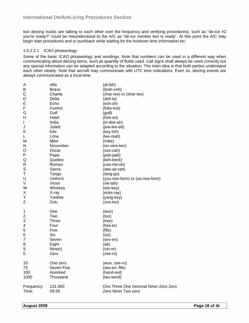
Some of the basic ICAO phraseology and wordings. Note that numbers can be used in a different way when communicating about deicing items, such as quantity of fluids used. Call signs shall always be used correctly but any special information can be adapted according to the situation. The main idea is that both parties understand each other clearly. Note that aircraft may communicate with UTC time indications. Even so, deicing events are always communicated as a local time. A Alfa (al-fah) B Bravo (brah-voh) C Charlie (char-lee) or (shar-lee) D Delta (dell-ta) E Echo (eck-oh) F Foxtrot (foks-trot) G Golf (golf) H Hotel (hoh-tel) I India (in-dee-ah) J Juliett (jew-lee-ett) K Kilo (key-loh) L Lima (lee-mah) M Mike (mike) N November (no-vem-ber) O Oscar (oss-cah) P Papa (pah-pah) Q Quebec (keh-beck) R Romeo (row-me-oh) S Sierra (see-air-rah) T Tango (tang-go) U Uniform (you-nee-form) or (oo-nee-form) V Victor (vik-tah) W Whiskey (wis-key) X X-ray (ecks-ray) Y Yankee (yang-key) Z Zulu (zoo-loo) 1 One (wun) 2 Two (too) 3 Three (tree) 4 Four (fow-er) 5 Five (fife) 6 Six (six) 7 Seven (sev-en) 8 Eight (ait) 9 Nine(r) (nin-er) 0 Zero (zee-ro) 10 One zero (wun, zee-ro) 75 Seven Five (sev-en, fife) 100 Hundred (hand-red) 1000 Thousand (tau-send) Frequency: 131,900 One Three One Decimal Niner Zero Zero Time: 09:20 Zero Niner Two zero
International De/Anti-icing Procedures Section
August 2008 Page 19 of 36
Some common phrases and their meaning. Note that common wordings shall not be used without confirming the sender and recipient. Acknowledge Say that you have received and understood the transmission Affirm A positive reply Approved Permission granted Check Inspect/verify something Confirm Make sure that something is done Contact Take radio contact with someone Correct The right way to proceed Correction Something said/informed wrongly and continued with the right message Disregard Do not note the previous message Go ahead Continue with transmission/procedure How do you read Verifying the transmission and readability Monitor Listen to the frequency Report Inform of the procedure Request Ask for something Roger Have received and understood the message (not recommended when multiple
communication is ongoing, needs a call sign verification) Say again Repeat the message Stand by Wait for the transmission to continue after a moment Verify Confirm/check/inspect something
1.6 Interpreting deicing/anti-icing fluid and hold-over-time tables
There are basically two different tables in use, generic and brandname. The generic table is developed using the lowest holdover times, attained from the certified fluids, for each cell. This table may show lower holdover times than the particular fluid actually provides but the idea is that the table can be used wherever these certified fluids are in use, regardless of brand. The brandname holdover timetable is attained for one particular fluid and cannot be used for any other fluids. If the fluid provided at some station is not the one for the table in use, then the generic table shall be used. The table may also vary in content, regarding columns used (e.g. snow, light snow, very-light snow), between organisations/countries (AEA-FAA/TC). Holdover time is obtained by anti-icing fluids remaining on the aircraft surfaces. With a one-step deicing/anti-icing operation the holdover time begins at the start of the operation and with a two-step operation at the start of the final (anti-icing) step. Holdover time will have effectively run out when frozen deposits start to form/accumulate on treated aircraft surfaces. Due to their properties, Type I fluids form a thin liquid wetting film, which provides limited holdover time, especially in conditions of freezing precipitation. With this type of fluid no additional holdover time would be provided by increasing the concentration of the fluid in the fluid/water mix. Type II, III and Type IV fluids contain a pseudoplastic thickening agent, which enables the fluid to form a thicker liquid wetting film on external aircraft surfaces. This film provides a longer holdover time especially in conditions of freezing precipitation. With this type of fluid additional holdover time will be provided by increasing the concentration of the fluid in the fluid/water mix, with maximum holdover time available from undiluted fluid. However, due to the many variables that can influence holdover time, these times should not be considered as minimum or maximum as the actual time of protection may be extended or reduced, depending upon the particular conditions existing at the time. Note that heavy precipitation rates or high moisture content, high wind velocity or jet blast may reduce holdover time below the lowest time stated in the range. Holdover time may also be reduced when aircraft skin temperature is lower than OAT. Therefore, the indicated times should be used only in conjunction with a pre-takeoff check. Certain fluids may be qualified according to fluid specifications but may not have been tested during winter to develop the holdover time guidelines. For use of holdover time guidelines consult Fluid Manufacturer Technical Literature for minimum viscosity limits of fluids as applied to aircraft surfaces. A degraded Type II, III or Type IV fluid may be used with the holdover time guideline for Type I fluids. A Type II, III or Type IV fluid is considered degraded if the viscosity is below the minimum limit as provided by the fluid manufacturer. The Type II fluid holdover time guideline may be used with degraded Type IV fluids only after substantiation by holdover time testing. Holdover time guidelines can also be obtained for individual fluid products and these ”brand name” holdover times will be found to differ from the tables published in a generic
International De/Anti-icing Procedures Section
August 2008 Page 20 of 36
holdover timetable. Deicing/anti-icing fluid used during ground deicing/anti-icing is not intended for and does not provide protection during flight.
1.7 Local frost prevention
Local frost prevention in cold soaked wing areas is a procedure to try to prevent the need for an actual deicing/anti-icing event at the departure time. Wing surface temperatures can be considerably below ambient temperature due to contact with cold fuel and/or close proximity to large masses of cold soaked metal. In these areas frost can build up on wing surfaces and may result in the entire wing being de-iced/anti-iced prior to the subsequent departure. This procedure is mainly aimed for the prevention of local frost formation in cold soaked wing tank areas during transit stops. This procedure does, however, not supersede standard deicing/anti-icing procedures. This procedure also does not relieve from any requirements for treatment and inspections in accordance with aircraft manufacturer manuals. The definition of local frost build-up is a limited formation of frost in local wing areas sub-cooled by cold fuel or large masses of cold metal; this type of frost does not cover the entire wing! For the procedure a suitable spray equipment should be used to apply a proper coating of undiluted Type II, III or IV anti-icing fluid on the wings in the limited cold soaked areas where formation of frost may be expected due to contact of the wing skin with sub cooled fuel or masses of cold metal. A proper coating completely covers the treated area with visible fluid. This preventive procedure is merely a precaution and it does not rule out clear ice checks or any other aircraft manufacturer requirements, nor the requirement that aircraft surfaces are clear of frost, slush/sleet, snow and ice accumulation. This local frost prevention procedure shall only be carried out if approved by the operator of the aircraft to be treated, and it shall only be carried out by properly qualified and trained personnel. This local frost prevention procedure shall be applied on clean wings immediately following arrival of the aircraft. Application is acceptable at the latest when frost just starts to build up, but in this case the fluid shall be applied at a minimum temperature of +50 °C. If precipitation occurred between application of the fluid and dispatch of the aircraft and/or if precipitation is expected before takeoff, a standard two-step deicing/anti-icing treatment shall be performed. Both wings shall receive the same and symmetrical treatment, also when conditions would not require the treatment of both wings. Note that aerodynamic problems could result if this requirement is not met. A holdover time shall not be assigned to a local frost prevention treatment since the treatment does not cover the entire aircraft or wing surface respectively. Since the anti-icing fluid is heated to +50 °C (when using the fluid for frost that just starts to build up) no minimum viscosity limits are relevant. Using this “flowing” fluid can cause it to drain off more quickly than normal thickened fluid. This can cause the wing to ice up at certain areas and it must be noted when inspecting the aircraft.
1.7.1 Manual deicing
Manual deicing is perhaps the only thing that has remained as a considerable option after all the different deicing procedures were developed. Manually cleaning an aircraft may seem very hard. Manual deicing can be either using brooms/brushes, using wing/propeller covers or using air blowers. All of these options will reduce the amount of contamination on the surfaces even if the surface is not fully clean. Deicing at the time of departure will be considerably faster and saves fluid if preliminary measures have been taken. Removing covers or using forced air is perhaps self-explanatory but the procedure of using brushes/brooms for deicing must be thought out before starting. Caution shall be taken when cleaning upper surfaces and safety harnesses shall be used. Consider the direction of sweeping so as not to direct snow or other contamination into gaps and cavities. A general direction from the front backwards is recommendable (note the differences of the external controls of the wings, e.g. spoilers, flaps and slats). The surfaces should be checked before starting, to note any possible ice underneath the snow. Light powdery snow is preferred to be removed manually. Normal deicing/anti-icing could lead to a deicing/anti-icing “cycle” (because of wet surfaces where similar light snow adheres) when flying to different stations (mainly short flights) simply because the process was started at the first departure point. Information of the procedure and any findings shall be given to the flight crew. The flight crew will decide on
International De/Anti-icing Procedures Section
August 2008 Page 21 of 36
further process for deicing and anti-icing. The need for inspecting the surfaces before departure is still required in spite of the manual deicing. Note that the clean surfaces after a manual deicing procedure shall not be considered as an anti-icing procedure.
1.7.2 Precautionary measures
Many aircraft and airport operations may have their own precautions to be noted in deicing operations. These requirements shall be noted and procedures followed accordingly. The training and operations program should include these elements. Such procedures can be e.g. preliminary deicing/anti-icing before departure, limitations on deicing/anti-icing for smaller aircraft such as turboprop A/C, fluid and gel residue problems and the limitations on operation. The basic concept is still a clean aircraft whether it is performed beforehand or performed for special aircraft. Particular aircraft operational limitations for a third party provider will be covered in differences training if not covered in their core training. Gel residue is a problem for non hydraulic power controlled aircraft. The thickened anti-icing fluid has a tendency to dry out on the surface/cavities and swell when in contact with water/fluid. This can be found when repeated treatments of anti-icing fluid is sprayed on the aircraft. The fluid dries and becomes almost invisible to see but when a mist of water is sprayed it can swell ten-fold. This swelled fluid, or gel, may cause a weight increase, instability and/or vibration in-between controls and when the aircraft reaches a higher altitude it can freeze. Furthermore it may block the movement of flight control surfaces. It is important to consider this phenomenon when performing anti-icing and precautions should be taken when necessary. Fluid residue can be found quite often on the trailing edges of the wing after a flight. If the temperature is low, this fluid may freeze or collect contamination when precipitation exists (e.g. dry powdery snow). Any contamination has to be removed prior to departure.
1.8 Alternative deicing/anti-icing methods
Alternatives may be forced air, forced air/fluid-mix, infrared deicing, infrared ice detection systems, non-glycol deicing fluids etc. In order for alternative methods to be used they must be contained in this chapter. It must be understood that some aircraft manufacturers may also have limitations on some operational alternatives and every aspect should be taken into account before their use.
International De/Anti-icing Procedures Section
August 2008 Page 22 of 36
2 OFF GATE DEICING/ANTI-ICING OPERATION
2.1 Airport operations
The operation of any deicing facility should maximize efficiency where possible. Local settings may demand one sort of operation for one airport that could be unusable for another location. There are gate deicing operations, centralised and remote deicing operations. A centralised deicing is merely a designated area for deicing (which could be a place on the apron or close to the runway) and a remote area is usually sited close to the departure runway. There should be flexibility in deicing, a mix operation is one solution for areas where there are no other restrictions for gate and remote deicing procedures. Aircraft types set their own requirements and limitations on how they are able to receive the deicing/anti-icing (e.g. propeller aircraft). Flight crew must be informed of local procedures involving them.
2.1.1 Precautionary measures
There are some elements that should be covered in the deicing procedures, such as: the manoeuvring of ground vehicles at the pad, the movement of aircraft at the pad, environmental limitations restricting operations, lighting system, the infrastructure itself (fluid filling, storage, shelters, coordination etc). The airport settings and requirements regarding deicing operations should be consulted. All the deicing/anti-icing procedures remain the same (e.g. pre- and post-checks, release, quality checks etc.) regardless of the place of operation. However, each new element (remote) adds procedures to the basic requirements of operation. These procedures should be carefully checked before the start of the operation, especially if the same deicing crew performs both gate deicing and at times remote deicing. All the variables should be covered in training.
2.1.1.1 Centralised/remote deicing/anti-icing
During off-gate deicing/anti-icing a two-way communication between pilot and deicing/anti-icing operator/supervisor shall be established prior to the deicing/anti-icing treatment. This shall be done by VHF radio or alternatively message boards. In case VHF is used, the register or “tail number” of the aircraft instead of flight number should be used during all communications. This procedure may vary for some locations and local operational procedures shall be adopted. During treatment all necessary information to flightdeck shall be given by this means (beginning of treatment, treatment of sections requiring de-activation of aircraft systems, anti-icing code, etc.). Contact with pilot may be closed after anti-icing code and readiness for taxi-out has been announced. When off-gate deicing/anti-icing area is entered by taxiing, a sufficient taxi and stopping guidance shall be arranged, or marshaller assistance shall be given. In case radio contact must be established before entering the deicing/anti-icing area, the signs with clearly marked operation frequency must be visible from the flightdeck before entering this area. The company together with the airport authorities must publish all necessary information about how to operate on the off-gate site by NOTAM or in local AIP. This information has to include at least the location of, and standard taxi routing to the deicing/anti-icing area, means to coordinate the deicing/anti-icing operation, means to communicate before and during the deicing/anti-icing operation and information about taxi and stopping guidance. The responsibility to determine the need for deicing/anti-icing before dispatch lies with the qualified person who performs the departure check at the gate. This information shall be given written or aurally to the Captain of the aircraft, who is after that responsible to proceed in order to get proper treatment. After treatment, the result shall be checked by a trained and qualified person and the anti-icing code shall be given to the Captain, after which the Captain is responsible for the airworthiness of the aircraft. The procedure on where to park ground vehicles and when to move around the aircraft are issues that need to be clearly defined and made aware to all users/operators. In general, no movement on the pad without a clear signal from a coordinator or team-leader, is allowed and no deicing/anti-icing operation can be performed before the A/C is ready and has given a go ahead. The logistics must be easily handled on a remote area unless the access to the ramp area is specifically routed. Filling deicing/anti-icing fluids and fuel for the vehicles must be well planned and a filling station should be positioned so that the additional operations do not effect the deicing
International De/Anti-icing Procedures Section
August 2008 Page 23 of 36
efficiency and throughput. Using a remote area where there are several deicing providers can be complicated unless a clear procedure has been planned. All providers should communicate to one coordinator. Moving around the remote pad without notification and communication can cause hazardous situations. The logistics should also be settled between all providers in case they are using different fluids.
2.2 Safety areas
The remote area may be able to handle different size aircraft at different positions or the area is set with a predetermined A/C stand procedure. As earlier mentioned, no movement shall be made on the pad without clearance from the coordinator or team leader. The vehicles shall stand in a safety area before and after the deicing/anti-icing is performed. This area shall be of sufficient size and placed where there is no risk of interfering with nearby aircraft moving to and from the pad. When deicing operations are performed simultaneously on nearby positions caution must be taken and the safety area should be of sufficient size to hinder the vehicles from colliding when positioning themselves inside the safety area. The safety area can be positioned either on both sides of the aircraft or on the end of the pad from where the ground vehicles move in each case. It is highly important to note that whenever giving the final release, the vehicle must be inside the safety area. There may also be different vehicles performing different tasks for a particular aircraft (e.g. underwing de-icer, check equipment etc.) and all movement around the aircraft must be coordinated. There may also be fluid suction trucks and apron cleaning/maintenance vehicles on the remote pad during deicing operations and these vehicles should also be in contact with the coordinator.
2.3 Deicing/anti-icing procedures
The procedure used for deicing and anti-icing at the remote area differs somewhat from a general gate deicing. The main difference is perhaps that the engines are running and additional procedures are required for the operation, such as added communication, safety area and positioning, coordination control, multiple vehicle deicing etc. All variations and differences from gate deicing must be included in both theoretical and practical training. A remote area does not exclude the need for anti-icing even if the area is close to the runway. Whenever there is precipitation, some form of anti-icing shall be performed and as earlier noted Type-I fluids have limited holdover times that may not be sufficient if the A/C needs to stand in line or hold before departure. If a mix operation is common procedure then it must be clear that the deicing crew is able to perform both duties and operate all equipment (if there are variations). Precautions must be noted, such as jetblast, engine inlet suction, APU running, moving aircraft etc. A preliminary selection of aircraft, that can be de-iced at the remote and aircraft that need to be de-iced at stand, must be decided. Certain limitations may also apply, such as snow or ice in areas on the A/C that is difficult (or comprises some hazard) to de-ice at the remote and needs to be pre cleaned before taxi. As a rule, A/C with turning propellers can not be de-iced, they need to be cleaned at stand (or otherwise propeller rotation halted). The remote area may have the possibility to provide electricity for start up and the procedures may differ in that case. It must be noted that the shutdown and start up of engines just before departure will add some time on the throughput for these particular aircraft and it may in some cases not be possible for the A/C to do so. Some aircraft have mandatory hands-on checks (e.g. wings and leading edges) and the deicing operation must be considered accordingly. The positioning of vehicles around the aircraft depends on the aircraft being de-iced/anti-iced and equipment in use. In general, only closed cabin versions of deicing vehicles should be used for a remote operation. This is a safety recommendation and it should be noted that jetblast, heat of the jetblast, engine inlet suction and noise are elements which hazard can be reduced by using closed cabin equipment. The amount of vehicles to use for a particular aircraft depends on the A/C size and availability of equipment. In general, two vehicles should be used as a minimum for each aircraft. Four vehicles will increase the efficiency of the deicing operation but it is not always possible to provide such an amount. It must be clear that there should be no driving behind the jetblast of a running engine and safety zones must be clearly defined. Note that the area is different for different aircraft but in general a sufficient distance from the jetblast shall be used (note idle and brake-off thrust).
International De/Anti-icing Procedures Section
August 2008 Page 24 of 36
2.3.1 Deicing/anti-icing spray- and operational procedures
The deicing/anti-icing spray operation on the remote area must be defined according to how many vehicles there are in use for each particular case. Generally two to four deicing vehicles can be used for deicing/anti-icing one aircraft and additional equipment for underwing and checks, if applicable. Two deicing vehicles are recommended as a minimum amount so as there would not be a need to drive behind the jetblast of the aircraft. Large aircraft are recommended to be treated with four vehicles whenever possible. If smaller propeller aircraft (assuming the propellers or engine can be stopped) are de-iced at the remote area, then one deicing vehicle can be sufficient. The size of the remote area and the operation at the area varies from one airport to another but the basic concept remains the same. The A/C surface areas to be de-iced and anti-iced must also be decided in order to start with the correct procedures. The procedure to use also depends on what kind of deicing vehicle is in use (with boom extension or a boomless spray). Assuming a vehicle with a boom is used and if the fuselage needs deicing, then the start would be at the front of the aircraft moving backwards, so the treated area of the fuselage would extend over the wing area at first. When approaching the wing, with the fuselage treated from the front over the wings, a normal deicing/anti-icing of the wing would be performed. The wings of conventional design usually are higher at the tip and lower at the root. This indicates that the procedure should be started from the wingtip and moved inwards. Some aircraft have a higher wingroot and thus the procedure should be continued from the root outwards. The procedure used for a high wingtip designed wing can be performed placing the vehicle halfway along the wing and thus with a boom extension all necessary areas can be reached in proper sequence. After the wings have been treated the aft-fuselage should be continued behind the wing but when reaching the tail section the spray procedure should be moved to cover the higher vertical stabilizer and treated downwards. After the vertical stabilizer has been treated, the aft-fuselage section at the tail root should be finished and the horizontal stabilizer should be treated. The vehicles should then move to the safety area from where the leading deicing vehicle (team-leader) should make the final release (anti-icing code). The general safety concept while deicing/anti-icing aircraft with engines running is to avoid the engine inlet and exhaust (jetblast). The equipment should be positioned in such a way that there is no danger of suction of foreign objects in the engines or that the jetblast could tilt the deicing vehicle or cause dangerous situations. With proper movement and positioning of the vehicle and boom extension, the procedure can be safely performed with regards to the A/C engine safety areas. When deicing/anti-icing large four engine aircraft, it would be recommended to shut down the outer engines. This procedure shall be verified with the flight crew (as any engine shut down/start up situation). If the outer engines cannot be shut down, then the procedure shall be adapted so that the vehicles move far enough behind the aircraft and in-between the exhaust (jetblast) “lines”, as close to the fuselage as possible, in order to be able to de-ice/anti-ice the aft-section and the tail. The front section and the wings can be treated as the vehicles drive between the engines (in-between safety areas). This procedure may be more time consuming but the safety of the operation must be at firsthand in mind. Note that the deicing coordinator will communicate with the flight crew of the aircraft, including any special situations, and will inform the deicing crew of the procedure. The teamleader will then organise the vehicles and the procedures around that particular aircraft. Note that a visual check is always mandatory whenever performing deicing/anti-icing. Some aircraft may also need a tactile check. Underwing deicing should be performed before the wing upper surfaces are treated. This is a safety issue, so as little as possible of the glycol runs on the vehicle windows (if upper surfaces would be treated first), that can impede visibility, while performing the underwing deicing.
2.3.2 Pre- and post- deicing/anti-icing checks
Deicing and anti-icing checks can be performed at the remote area but this is very limited. Required pre- and post-checks do not vary according to where the deicing/anti-icing is performed. Proper checks and the determination of the need for deicing should be performed at the stand/gate where there is more time, proper equipment and no hazard of running engines. The differences of required checks to be performed may vary between companies, and the procedure must be clear to all involved. A visual check is always performed but tactile checks need special equipment at the remote area. Some aircraft may be limited by aircraft directives and thus mandatory checks have to be performed accordingly. All required procedures must be clear before the
International De/Anti-icing Procedures Section
August 2008 Page 25 of 36
aircraft taxis to the remote area. The coordinator will inform the deicing crew of all requests and optimises the operation. The decision to pre-treat the aircraft at stand should also be made in good time in order to coordinate the operation. Note that the anti-icing code, in itself, always contain a verification that the areas are clean (and protected) and checked.
2.4 Management of the centralised deicing/anti-icing operation
A management and procedure plan should be available at the airport in relevant publications. This program shall explain the necessary procedures of the deicing operation. The remote deicing operation must be clearly determined and informed to all stakeholders. A deicing program must be established irrespective of if it is a remote only or a mix operation. The procedures, the throughput, the options, the checks, the communication etc. must be clearly defined and responsible persons must be introduced. A remote deicing operation (including a mix) must have a coordination operation. The operation should be established accordingly even if there are several deicing providers using the same area. Logistics of the deicing operation must be clear and not hinder the operation. The area of responsibility, the decision of where to de-ice must be clear and such procedures must be communicated with the ATC. The operation may vary according to what each airport can provide, how long the season is and how the peak hours are divided. The deicing equipment may also limit the possibilities. A dialog should be established periodically with the stakeholders to discuss and agree on procedures. The on-time departure benefits all and the “provider-customer” scenario must be planned accordingly to be as effective and efficient as possible.
International De/Anti-icing Procedures Section
August 2008 Page 26 of 36
3 AIRCRAFT TYPES
3.1 Consideration of aircraft variations
All aircraft related limits shall be taken into account and the differences informed to the deicing crew. The application of deicing/anti-icing fluid shall be in accordance with the requirements of the airframe/engine manufacturers and this chapter. The local winter operation plan should reflect the particular airport and the aircraft it serves (e.g. passenger traffic, cargo, and business). There are also a wide variety of aircraft to consider (e.g. small transport, medium-large transport, business jets, propeller aircraft etc.). It is impractical to remember each aircraft type and its particular limitations so a more general approach is in place. Use no-spray diagrams as a refresher when possible. Aircraft differences will be provided when necessary.
3.1.1 Aircraft no-spray areas in general
Basic areas of caution when deicing/anti-icing are engine-inlets, APU inlet/exhaust, windows, doors/seals, brakes/landing gear, vents, probes, sensors, cavities and any opening where sprayed fluid is not allowed. Additionally composite parts may have their own limitations regarding deicing fluids and temperatures, such as composite propellers. There are many variations but these general areas shall be avoided whenever possible. Some splashes of fluid and fluid drained cannot be avoided but direct spray on these parts is not allowed. Areas where fluid is allowed to be sprayed (e.g. the radome), but from where fluid flow-off can cause some problems (e.g. fluid flowing from the nose section on the windows during takeoff), should be noted and the procedure should be discussed together with the flight crew. The reasons why these areas are restricted and the consequences of what might happen if glycol/fluid is sprayed should be understood. Such incidents may be that sensors give false readings, engine and APU produce smoke inside the aircraft via the air intake (or break), glycol may stick on heated flightdeck windows causing restricted view for the flight crew etc.
3.1.1.1 APU
The APU is critical for deicing fluid and no spraying shall be directed towards the inlet or exhaust. There have been a number of cases where the APU has been destroyed due to deicing fluids and some aircraft have restrictions of use during deicing. The procedure for each case must be clear and general avoidance shall be noted. Engines are normally shut down but may remain running at idle during deicing/anti-icing operations. Air conditioning and/or APU air shall be selected OFF, or as recommended by the airframe and engine manufacturer. All the preparations should be performed beforehand so the deicing/anti-icing operation is not interrupted. Proper communication shall be established so the procedure can be performed accordingly. Aircraft in general have their APU situated in the aft tail section. The APU intake can be on either side of the tail as well as the exhaust. Older design (and some eastern production) can have the APU located in the landing gear section under the wing/fuselage and the exhaust directed through the wing or the wing root. The air-conditioning is usually in operation whenever the APU is. This can cause glycol to be sucked in the air system and thus produce smoke inside the cabin. The flight crew shall be informed before the start of the deicing so they can make the appropriate adjustments.
3.1.2 Jet-aircraft vs. propellers
Normal jet-engine aircraft are perhaps the conventional aircraft to de/anti-ice. Even so, many propeller aircraft perform a variety of flights and need deicing/anti-icing just as any other aircraft. The procedure in itself does not vary because of engine differences. The wings, tail and fuselage are treated the same way. There may be differences on what sort of anti-icing is allowed (thickened fluid) or how the anti-icing fluid affects performance. The propellers may have some requirements on how to de-ice or simply to avoid deicing. Note that the deicing check also includes the propellers. Propeller aircraft are generally treated at the stand because rotating propellers cause a hazard. If the procedure is performed at a remote area, appropriate procedures shall be established and engine shutdown/start-up procedures (if performed) shall be well known. Some propeller aircraft have the possibility to stop the rotation of the propeller for a limited time (prop-brake). If the deicing/anti-icing is performed and engines are started, whether it is on a remote or at stand, the correct sequence shall be known and communicated. The aircraft is said to have a left-hand and a right-hand side according to the captain’s view forward. The engines are also numbered according to the captain’s view starting from left to right (number one
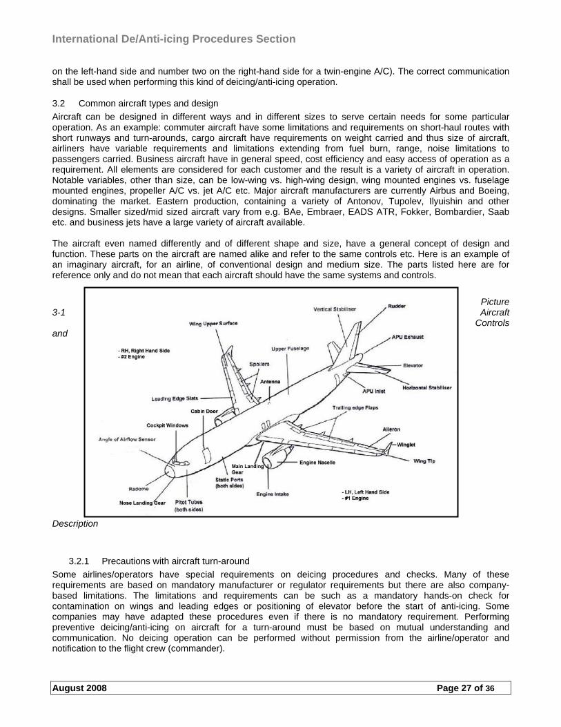
International De/Anti-icing Procedures Section
August 2008 Page 27 of 36
on the left-hand side and number two on the right-hand side for a twin-engine A/C). The correct communication shall be used when performing this kind of deicing/anti-icing operation.
3.2 Common aircraft types and design
Aircraft can be designed in different ways and in different sizes to serve certain needs for some particular operation. As an example: commuter aircraft have some limitations and requirements on short-haul routes with short runways and turn-arounds, cargo aircraft have requirements on weight carried and thus size of aircraft, airliners have variable requirements and limitations extending from fuel burn, range, noise limitations to passengers carried. Business aircraft have in general speed, cost efficiency and easy access of operation as a requirement. All elements are considered for each customer and the result is a variety of aircraft in operation. Notable variables, other than size, can be low-wing vs. high-wing design, wing mounted engines vs. fuselage mounted engines, propeller A/C vs. jet A/C etc. Major aircraft manufacturers are currently Airbus and Boeing, dominating the market. Eastern production, containing a variety of Antonov, Tupolev, Ilyuishin and other designs. Smaller sized/mid sized aircraft vary from e.g. BAe, Embraer, EADS ATR, Fokker, Bombardier, Saab etc. and business jets have a large variety of aircraft available. The aircraft even named differently and of different shape and size, have a general concept of design and function. These parts on the aircraft are named alike and refer to the same controls etc. Here is an example of an imaginary aircraft, for an airline, of conventional design and medium size. The parts listed here are for reference only and do not mean that each aircraft should have the same systems and controls.
Picture 3-1 Aircraft
Controls and
Description
3.2.1 Precautions with aircraft turn-around
Some airlines/operators have special requirements on deicing procedures and checks. Many of these requirements are based on mandatory manufacturer or regulator requirements but there are also company-based limitations. The limitations and requirements can be such as a mandatory hands-on check for contamination on wings and leading edges or positioning of elevator before the start of anti-icing. Some companies may have adapted these procedures even if there is no mandatory requirement. Performing preventive deicing/anti-icing on aircraft for a turn-around must be based on mutual understanding and communication. No deicing operation can be performed without permission from the airline/operator and notification to the flight crew (commander).
International De/Anti-icing Procedures Section
August 2008 Page 28 of 36
4 4 DE-ICING/ANTI-ICING EQUIPMENT
4.1 Variations of deicing/anti-icing equipment
There are many different vehicles on the market that are able to perform the deicing operation. They are all lifting devices that require a specific training before use. Certain manufacturers provide special equipment for underwing spraying. Even if this is not a man-lift device, the vehicle cannot be operated without proper training.
4.1.1 Equipment safety precautions
The deicing vehicle contains many areas where safety precautions must be noted. Some of these areas to be noted are the use of hot fluids, the high pressure of the spray, large and heavy vehicles moving around aircraft, precautions when filling the vehicle, precautions when using the boom and manoeuvring, communication between the sprayer and the driver (where applicable), the at times poor visibility while spraying, the use of safety harnesses among other things. The use of the vehicle should be performed in a manner that the following user can continue without any doubts of the safe performance of the vehicle. Any discrepancies shall be informed and noted, and measures shall be taken to indicate to other users that the vehicle may not be usable or that the use is limited. Check vehicles for proper operation before use. The basic operation shall be verified and discrepancies noted. The different systems used in the vehicle should be checked for proper performance, e.g. fluid quantity indication, burner and other similar elements that have to do with the proper operation of the vehicle. Additional equipment shall be checked and located (e.g. safety harnesses, hearing protectors, fire extinguisher). The vehicle should be checked for all fluids needed when in use (e.g. windshield washing fluid, fuel etc.). Note that the vehicle is usually used in areas where space is limited, where visibility can be limited and where the surface is slippery due to ice or the mix of glycol on the ground. It is recommended to test the brakes before approaching the aircraft to verify how slippery the surface is and in general test the performance of the brakes.
4.1.1.1 Emergency requirements
A certain amount of emergency solutions are mandatory for a deicing vehicle to make sure that some particular situations can be solved or prevented. The emergency system must contain an emergency stop/emergency shut off system at key points around/in the vehicle, an emergency lowering system of the boom, a fire extinguisher and a system to prevent any overheating, overfilling and overpressure in the deicing fluid system. A way of communicating must be in place in order to be able to solve situations with the person in the basket/cabin. The operation and monitoring of these systems shall be included in the training and each different vehicle requires similar type training.
4.1.2 Operational use of equipment and quality control
There are some limitations on the use of deicing vehicles. These limitations refer, among others, to the maximum wind velocity with the boom elevated, operational speed in deicing/anti-icing, movement velocity of the boom, load capacity of the basket/cabin, spray pressure and heat of fluids. The vehicle boom extension must be in proportion to the average aircraft serviced at the airport. Some aircraft have a height of up to 25 m, but an average height is between 13-15 m for large transports and under 10 m for small transports. The boom (basket) in itself may not in some case extend to the particular height required but there may be an extending nozzle boom that covers the remaining distance. It must be noted that the further away the spraying is performed the less heat and pressure is transferred to the aircraft surface. Note that the area sprayed shall also be visually checked. Any particular limitations and/or requirements shall be referred to in the current deicing vehicle standards and manufacturers’ publications. Some requirements need to be tested and verified for use, such as the spray system, emergency system, visibility during operation, controls, monitoring devices and displays, lights, speeds, warning devices, braking and steering. The vehicle also need labelling at all appropriate areas, such as hoses, fluids, filling ports, instructional plates etc. Labelling of different hoses and filling ports is important so no confusion would exist when performing deicing and anti-icing respectively. Since some operators use uncoloured deicing and anti-icing
International De/Anti-icing Procedures Section
August 2008 Page 29 of 36
fluids, this aspect is even more important. Spray tests must be performed periodically for thickened fluid in order to verify that the vehicle (pumps, nozzles etc.) do not degrade the viscosity of the fluid when sprayed. There are many variables to consider and to note when using the vehicle. It is up to each operator to make sure these functions are working and that they have been appropriately maintained. A maintenance schedule shall be introduced and recorded. The quality control also includes a verification of the fluid used (visual and refractive index/freezing point) and a verification of the fluid temperature. Many vehicles have temperature measurements from the tank but temperature at the nozzle shall also be verified (+60 °C for Type-I/water mix when used as anti-icing and +50 °C for thickened fluid when used for preventive deicing for frost building up). The vehicle may also be able to provide data for the customer after each deicing event (if requested). Minimum parameters shall be recorded, such as the date, aircraft de-iced/anti-iced, fluid used/mixtures and holdover time started. Additional data is usually collected and thus also provided.
4.1.2.1 Filling station
Each filling station is designed to serve the particular vehicles in use. The filling of fluid can be performed by an automated system controlling the level of fluid in the vehicle tank or manually either with separate containers or by filling through manholes. It must be noted that all hoses, containers and filling ports (including manholes) shall be marked with the appropriate label of fluid contained. Care should be taken so as not to mix fluids. Application equipment shall be cleaned thoroughly before being initially filled with deicing/anti-icing fluid in order to prevent fluid contamination. Deicing/anti-icing fluid in trucks shall not be heated in confined or poorly ventilated areas. The heating of fluids in containers/tanks may be performed electrically or not heated at all (anti-icing fluid is generally not heated). Cold fluid can be filled in the tanks if the vehicle is equipped with a burner that heats up the fluid before spraying. Thickened fluid is not heated in either the vehicle or at the filling station (unless used diluted as a deicing fluid). The level/amount of fluid and fluid temperatures both for the filling station and vehicles parked should be monitored in order to secure a sufficient amount and sufficiently heated fluid when needed. The operation of the filling station shall be included in the training and all necessary precautions noted.
4.1.3 Equipment communication requirements
The deicing vehicle needs to have an appropriate communication system that is suited for the operation in use, e.g. VHF, UHF, mobile phone etc. A two-way communication needs to be established between the vehicle and the aircraft (or the coordinator). This communication needs to be performed via VHF-radio. The radio needs to be approved for use for aviation frequencies. An intercom communication (or similar) needs to be established when two persons are operating the vehicle. The external noise should be noted (e.g. aircraft engines) when using a headset type communication in open basket vehicles. External noise can disrupt the communication and care should be taken so as not to continue the deicing operation with misleading or no communication at all. When two or more vehicles are deicing an aircraft, other communication possibilities may be considered between these vehicles. Communication between vehicles is needed in order to verify proper treatment and procedures. The chain of communication depends on how the particular winter operation is planned and performed. Some use a coordinator (or team leader) for all the communication between the aircraft while others perform the communication from each vehicle. Certain airports have separate frequencies for different areas of deicing operation. The communication equipment must be suited for the local setting and the personnel trained accordingly.
4.1.4 Equipment fluid use and spray alternatives
As earlier mentioned, there are variations between equipment. The variations also reflect on how the deicing/anti-icing fluids are stored in the vehicle and how it is sprayed. Basically the fluids can be either premixed before use or a proportional mixing system according to selection will mix the appropriate solution of glycol and water. Thickened fluid is not generally mixed with water but may be if fluid is diluted as a deicing fluid. The differences are mainly dependent on what particular need each station has and how local settings are set up. Vehicles using pre-heated fluid should monitor the temperature. Vehicles using so-called burners should verify the correct temperature while spraying. Note that when the vehicle has not been in use for some time, it may take time to reach the proper temperature at the nozzle. Where fluid tanks are heated there is normally a need for insulation, as the heat loss from a full tank should not exceed 1 °C/hour. The heating of water/Type-I can also generate heat for the thickened fluid. This should be
International De/Anti-icing Procedures Section
August 2008 Page 30 of 36
monitored so the temperature would not rise too high. The fluid flow depends on the particular fluid used and the equipment in use. Generally a flow rate of 20 – 100 l/min may be used for non-Newtonian fluids (thickened). The demand is that the viscosity loss is minimal after pumping and spraying so as not to degrade the fluid below the minimum viscosity. The pumps, lines and nozzles should be such that minimum viscosity loss is achieved after spraying. The demand of spray pressure and flow rate depends largely on elements such as the contamination on aircraft surfaces, wind conditions, temperature of fluid, spraying distance etc. Generally a 50 – 275 l/min flow rate at a pre-nozzle discharge pressure of 650 kPa with the boom fully elevated will be suitable for any deicing task. To perform an effective deicing operation, the de-icer should have full control over the movement of the nozzle. It is necessary for the nozzle to be able to vary the pattern between a cone shaped and solid stream, and the flow rate from minimum to maximum. The system should be able to indicate any mixing problems or be designed so that the mixture would become stronger instead of leaner if something fails. Make periodical and daily checks for the fluids as well as visual checks according to current standards and recommendations to make sure that correct mixtures are used. The deicing fluid (lean mixture) and water in the lines may freeze if cold temperatures exist. Purging the lines, filling them with a high concentration of glycol will eliminate this. In turn when deicing the aircraft after purging the lines, it must be noted that a certain amount of fluid needs to be sprayed before the correct mixture is reached at the nozzle.
4.1.5 Data collection
To comply with regulations and enable useful evaluation and follow-up of operator performance, establish a system for recording and controlling operations. The data is usually computerised and the system records automatically some parameters (e.g. mixtures, time of deicing and time of anti-icing etc.) but this can also be recorded manually. The details fed into the system (e.g. flight number, aircraft type, areas treated, duration of operation, volume and type of fluid used, temperature etc.) will depend on the particular setting and vehicle system. The data should be at hand to be presented when requested. The data is also an invoicing requirement unless otherwise settled between operators/airlines. There are different ways of providing and recording this data, such as instant invoice capability or remotely via the coordinator or as a hand made receipt. Some airports also need verification of where and how much deicing fluid has been used. This data should be recorded as seasonal information and not needed on a daily basis. Some companies also require Internet based record keeping for all deicing events in order to fulfil certain aircraft specific data analysis and reporting as well as the generally required event information. The minimum information required is listed below:
a) The fluid type (e.g. Type I, II, III, IV) b) The concentration of fluid within the fluid/water mixture, expressed as a percentage by volume. Note that
this is no requirement for Type I fluid c) The local time (hours/minutes) at the beginning of the final deicing/anti-icing step d) The date (written: day, month, and year). e) gate/location f) truck/boom g) station h) operator flight number or aircraft registration i) identification of applicator
International De/Anti-icing Procedures Section
August 2008 Page 31 of 36
5 DEICING/ANTI-ICING COORDINATION
5.1 General
Any winter operation needs a coordinated effort to produce an effective and efficient deicing procedure. Establish coordination according to the local needs and settings. If the deicing volume is reasonably large then a coordination system is a must. Coordination can be established for both gate and remote deicing operations, they can even serve both procedures simultaneously. The area of responsibility lies with the allocation of deicing work, the control of deicing vehicle resources for aircraft, management of deicing events, communication control, safety considerations and special occurrences (problem solving) or ad-hoc situations. Local requirements must be followed and the procedures adapted accordingly.
5.2 Management of deicing/anti-icing procedures
When establishing a local (winter operation) coordination management plan, consider the volume of deicing events, where should the emphasis be made for an effective coordination, what is the expected outcome of the coordination, can the coordination serve other customers, are all stakeholders involved, what sort of infrastructure is needed, does the season and climate set any requirements for the coordination, what are the local limitations. Make the coordination as easily managed as possible without compromising safety, efficiency and effectiveness of deicing operations but at the same time involving all stakeholders. An ideal place to coordinate is somewhere with good visibility, good communication possibilities (ATC, ground support divisions, aircraft and all deicing vehicles), possibility for problem solving with relevant stakeholders and easy access for personnel. The volume of deicing events is relevant when building up a system. The benefits of a good coordination system are that there is always someone standing by and situations can be solved without complex procedures. The season of deicing should be clear when there is a need to establish a “stand by crew”. Note that even summer operations may have the need for a deicing (ref. clear ice) and a back-up plan for such events should be clear. It is recommended to have an agreement with a ground service provider (or similar) who is always present and can offer back-up service when the main deicing staff is unavailable. Note that anyone performing deicing/anti-icing must be trained and qualified.
5.2.1 Coordination recommendations
The coordinator must have good experience of winter operations and be able to solve situations as they appear. Relating requirements are explained in Training Section. The coordinator must be able to handle several deicing situations at different times of operation. Some items included in the procedures may be to organise resources, control vehicle fluid consumption and filling according to the flow of aircraft, verify quality of fluids, give taxi instructions at the centralised deicing area (or provide contact information), involve stakeholders (e.g. apron suction trucks, other operators), record keeping and to be a source of information (troubleshooting) when needed. The coordinator is constantly monitoring all communications and operations and can therefore supervise the safety of deicing operations. The coordinator may need to be aware of environmental aspects and monitor the operations accordingly. Fluid availability and logistics is one important part of coordinating a deicing operation. The coordinator should be able to provide the flight crew with pertinent information of the deicing procedure if the deicing crew is unable to provide such information. Note that at remote areas other deicing providers may share the same deicing pad but not the same coordination. This situation should be clarified beforehand and procedures should be set up for mutual understanding and foremost because of safety.
5.2.2 Communication procedures
The coordinator has a role of supervising correct communication between the de-icers to the aircraft and correcting possible misunderstandings. Refer to section 2 for off gate deicing/anti-icing communications. The basic communication does not change with or without a coordinator. Communication can be performed via VHF (normally) or by any other means (e.g. message boards, UHF, phone etc.). If the coordinator acts as a team leader among the deicing group, communication can be provided by intercom (headsets) to the aircraft. Note that if the coordinator gives a final release code, it must be made sure that all vehicles are clear from the aircraft and in a safety area before communicating. Visual indication of the procedures shall be made possible for the coordinator in order to provide correct and exact information of the situation. Aircraft may ask questions
International De/Anti-icing Procedures Section
August 2008 Page 32 of 36
regarding the fluid, holdover time and/or the procedure itself and necessary information must be readily available by the coordinator.
5.2.3 Safety considerations
It is up to the deicing coordinator to verify deicing/anti-icing procedures and take into account variations between company procedures. This information must be informed to the deicing crew whenever relevant. The deicing coordinator is responsible to control the movement of deicing vehicles on the ramp and the remote area. Safety issues shall be noted and informed/reminded to the deicing crew. Emergency situations shall be considered beforehand and a plan of such events shall be available. Issues like personnel accidents, collision with aircraft, accidents with fluid handling etc. must be considered and a procedure must be followed accordingly. The coordinator shall have contact with relevant parties to solve the situation and act according to the situation. Procedures shall be practised and communication channels must be organised. Relevant safety aspects must be considered in the winter operation program and such procedures must be emphasised by the coordinator.
5.2.4 Airport layout and local compliance
The airport infrastructure must support the winter operations. The deicing coordination is one key point in operating an effective winter operation. This part of the process should support other elements that are relevant for a safe and on-time departure. The location of the deicing coordinator is important in order to control the operation. Visibility to the ramp (and remote) should be made available on site or by cameras. The location, visibility and communication elements are even more important when the operation is spread out. More than one coordinator may be necessary according to the peak hours and operation as a whole. The coordinator may be in contact with other airlines, ramp cleaning, A/C positioning, ATC etc. and it is therefore important to have a good dialogue with these relevant stakeholders in order to make the process as effective and safe as possible. Local regulations and restrictions must be noted and the operation must be adapted accordingly.
International De/Anti-icing Procedures Section
August 2008 Page 33 of 36
INDEX
A
AEA 19 aerodynamic 2, 3, 7, 8, 13, 20 aerodynamic surfaces 7 ailerons 8 Airbus 27 aircraft manufacturer 11, 20 aircraft surfaces 3, 8, 10, 11, 15, 19, 20, 30 aircraft types 27 airflow 8 angle of attack 8 anti-icing 2, 3, 4, 5, 7, 8, 9, 11, 12, 13, 14, 15, 16, 17, 19, 20, 21, 22, 23, 24,
25, 26, 27, 28, 29, 30, 31, 32 anti-Icing code 16 Anti-Icing Code 14 Antonov 27 apu 16, 23, 26 arrival 11, 16, 20
B
Boeing 27 Bombardier 27 boom 24, 28, 30 brand name 2, 16, 19
C
cavities 8, 9, 20, 21, 26 centralized de-icing 7, 9, 22 check 2, 3, 4, 5, 7, 14, 16, 19, 22, 23, 24, 26, 27 clean aircraft concept 7, 9 Communication 29, 31 concentration 2, 3, 4, 5, 8, 16, 19, 30 contamination 2, 3, 4, 7, 8, 9, 10, 14, 20, 21, 27, 29, 30 coordination 22, 23, 25, 31, 32 co-ordinator 7, 15, 16, 17, 22, 23, 24, 25, 29, 30, 31, 32 critical surfaces 7
D
de-icing 2, 3, 4, 5, 7, 8, 9, 10, 11, 12, 13, 14, 15, 16, 17, 18, 19, 20, 21, 22, 23, 24, 25, 26, 27, 28, 29, 30, 31, 32
De-icing/anti-icing 3, 17, 29 De-icing/Anti-icing 7, 28, 31 departure 8, 11, 15, 16, 20, 21, 22, 23, 25, 32
E
EADS 27 efficient 25, 31 elevator 9, 27 Embraer 27 engines 7, 8, 10, 16, 17, 23, 24, 26, 27, 29 equipment 3, 4, 7, 8, 10, 14, 16, 20, 23, 24, 25, 28, 29, 30 examination 15
International De/Anti-icing Procedures Section
August 2008 Page 34 of 36
F
FAA 19 falling ball 5 final release 17, 24, 31 flaps 17, 20 flight crew 7, 14, 15, 16, 20, 24, 26 fluid 2, 3, 4, 5, 7, 8, 9, 10, 11, 12, 13, 14, 15, 16, 17, 19, 20, 21, 22, 23,
26, 28, 29, 30, 31, 32 foam 10 Fokker 27 freezing 3, 8, 9, 10, 11, 12, 13, 19, 29 frequency 18, 19, 22 frost 7, 8, 10, 11, 14, 15, 16, 20, 29 fuselage 9, 17, 24, 26, 27
G
Gate de-icing 9, 16 generic 19 glycol 8, 10, 21, 24, 26, 28, 29, 30 ground crew 7, 16 ground service 31
H
heating 3, 29 high humidity 9 holdover time 8, 11, 15, 18, 19, 20, 29, 32 holdover timetable 19, 20 horizontal stabilizer 9 hot air 8, 10
I
ICAO 17, 18 ice 3, 7, 8, 9, 10, 11, 14, 15, 17, 18, 20, 21, 23, 24, 25, 26, 28, 31 inspection 3, 4, 7, 9, 16
J
jetblast 17, 23, 24
L
laboratory 3 leading edge 8, 9 limitations 8, 9, 17, 21, 22, 23, 26, 27, 28, 31 local frost prevention 20
M
manual 21 mix operation 22, 23, 25 mixture 3, 5, 7, 8, 9, 11, 12, 16, 30
N
noise 23, 27, 29 nozzle 3, 4, 5, 10, 11, 12, 28, 29, 30
O
One-step 8
International De/Anti-icing Procedures Section
August 2008 Page 35 of 36
operation 3, 7, 8, 11, 12, 14, 15, 16, 17, 19, 21, 22, 23, 24, 25, 26, 27, 28, 29, 30, 31, 32
operator 20, 22, 29, 30
P
performance 2, 3, 26, 28, 30 phraseology 17, 18 pH-value 3, 4 practical 23 precipitation 5, 8, 9, 11, 15, 19, 20, 23 procedures 2, 3, 5, 7, 8, 9, 10, 11, 12, 14, 15, 16, 17, 18, 20, 21, 22, 23, 24,
25, 26, 27, 29, 31, 32 program 21, 22, 25, 32 propeller 17, 20, 22, 24, 26, 27 purging 4, 30
Q
qualification 2 qualified 7, 14, 15, 19, 20, 22, 31 quality control 28, 29
R
recommendations 3, 31 Records 3 refractive index 2, 3, 5, 29 regulations 7, 32 remote de-icing 7, 16, 17, 22, 25, 31 residue 10, 21 responsibility 22, 25, 31 rudder 9
S
Saab 27 SAE 19 safety 3, 4, 9, 15, 17, 20, 23, 24, 28, 31, 32 Safety 23, 32 sampling 3, 4 shearing 3 slats 20 slush 8, 10, 15, 20 snow 8, 10, 11, 15, 17, 19, 20, 23 spraying 3, 10, 11, 26, 28, 29, 30 standards 4 storage tank 3, 4
T
tail 7, 9, 16, 17, 22, 24, 26 takeoff 3, 8, 9, 11, 15, 16, 19, 20, 26 TC 19 team leader 15, 16, 29, 31 temperature 3, 4, 8, 9, 10, 12, 13, 15, 19, 20, 21, 29, 30 tested 5, 19, 28 tests 29 theoretical 23 throughput 23, 25 trailing edge 8, 9, 10
International De/Anti-icing Procedures Section
August 2008 Page 36 of 36
training 21, 22, 23, 28, 29 treatment 7, 9, 11, 14, 15, 16, 17, 20, 22, 29 Tupolev 27 turn-around 27 turn-arounds 27 Two-step 8 Type-I 2, 3, 13, 29 Type-II 2 Type-IV 2
U
underwing 9, 23, 24, 28
V,W
vehicle 2, 3, 4, 5, 7, 15, 16, 17, 23, 24, 28, 29, 30, 31 Vertical stabilizer 9 wing 9, 11, 15, 17, 20, 21, 24, 26, 27 winter operations 31, 32 viscosity 3, 5, 13, 19, 20, 29, 30
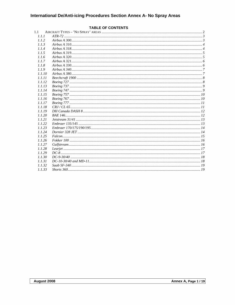
International De/Anti-icing Procedures Section Annex A- No Spray Areas
August 2008 Annex A, Page 1 / 19
TABLE OF CONTENTS 1.1 AIRCRAFT TYPES – ’NO SPRAY’ AREAS ................................................................................................................. 2
1.1.1 ATR-72 ........................................................................................................................................................... 3 1.1.2 Airbus A 300................................................................................................................................................... 3 1.1.3 Airbus A 310................................................................................................................................................... 4 1.1.4 Airbus A 318................................................................................................................................................... 4 1.1.5 Airbus A 319................................................................................................................................................... 5 1.1.6 Airbus A 320................................................................................................................................................... 5 1.1.7 Airbus A 321................................................................................................................................................... 6 1.1.8 Airbus A 330................................................................................................................................................... 6 1.1.9 Airbus A 340................................................................................................................................................... 7 1.1.10 Airbus A 380................................................................................................................................................... 7 1.1.11 Beechcraft 1900 ............................................................................................................................................. 8 1.1.12 Boeing 727 ..................................................................................................................................................... 8 1.1.13 Boeing 737 ..................................................................................................................................................... 9 1.1.14 Boeing 747 ..................................................................................................................................................... 9 1.1.15 Boeing 757 ................................................................................................................................................... 10 1.1.16 Boeing 767 ................................................................................................................................................... 10 1.1.17 Boeing 777 ................................................................................................................................................... 11 1.1.18 CRJ / CL 65.................................................................................................................................................. 11 1.1.19 DH Canada DASH 8.................................................................................................................................... 12 1.1.20 BAE 146........................................................................................................................................................ 12 1.1.21 Jetstream 31/41 ............................................................................................................................................ 13 1.1.22 Embraer 135/145 ......................................................................................................................................... 13 1.1.23 Embraer 170/175/190/195........................................................................................................................... 14 1.1.24 Dornier 328 JET .......................................................................................................................................... 14 1.1.25 Falcon........................................................................................................................................................... 15 1.1.26 Fokker 100 ................................................................................................................................................... 16 1.1.27 Gulfstream.................................................................................................................................................... 16 1.1.28 Learjet .......................................................................................................................................................... 17 1.1.29 DC-8 ............................................................................................................................................................. 17 1.1.30 DC-9-30/40 .................................................................................................................................................. 18 1.1.31 DC-10-30/40 and MD-11............................................................................................................................. 18 1.1.32 Saab SF-340................................................................................................................................................. 19 1.1.33 Shorts 360..................................................................................................................................................... 19
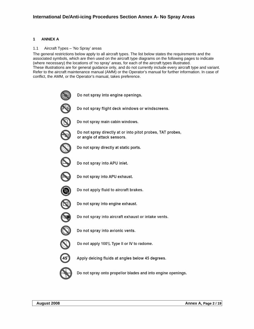
International De/Anti-icing Procedures Section Annex A- No Spray Areas
August 2008 Annex A, Page 2 / 19
1 ANNEX A
1.1 Aircraft Types – ’No Spray’ areas
The general restrictions below apply to all aircraft types. The list below states the requirements and the associated symbols, which are then used on the aircraft type diagrams on the following pages to indicate (where necessary) the locations of ‘no spray’ areas, for each of the aircraft types illustrated. These illustrations are for general guidance only, and do not currently include every aircraft type and variant. Refer to the aircraft maintenance manual (AMM) or the Operator’s manual for further information. In case of conflict, the AMM, or the Operator’s manual, takes preference.
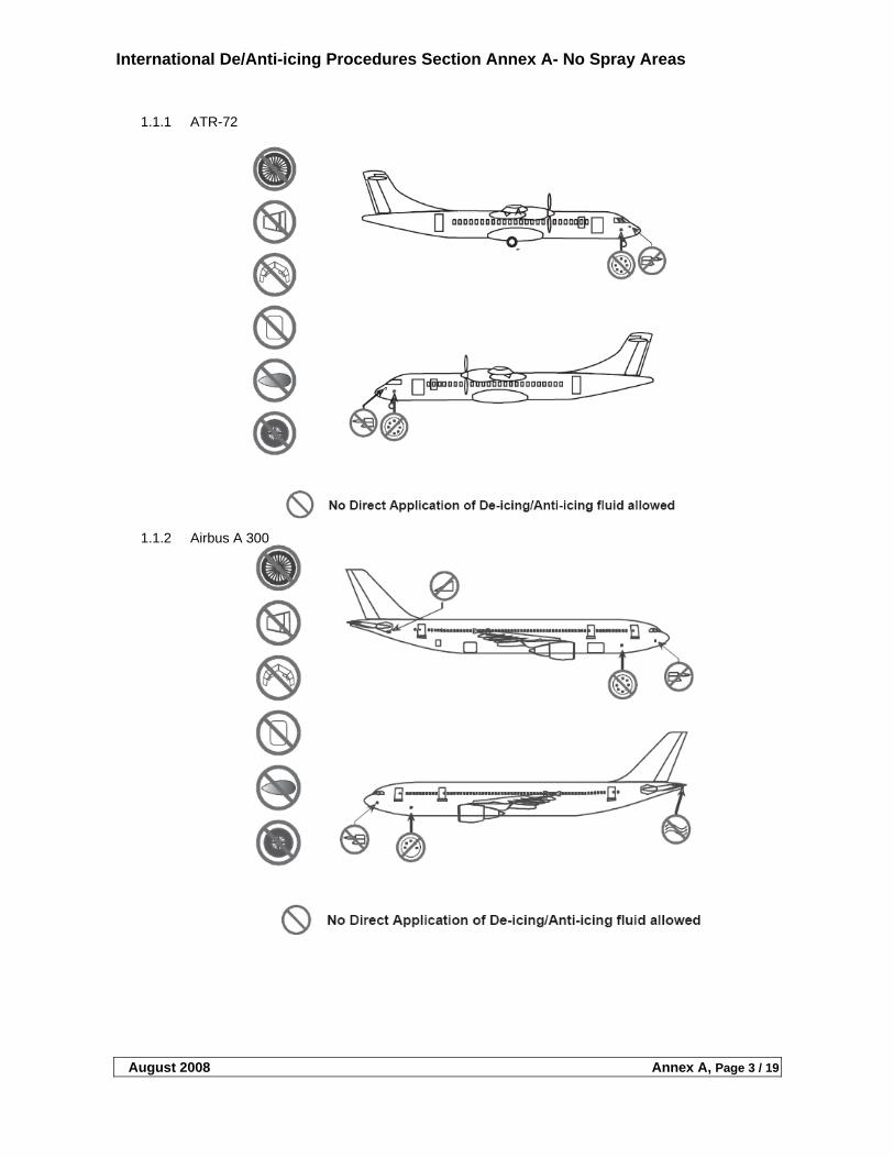
International De/Anti-icing Procedures Section Annex A- No Spray Areas
August 2008 Annex A, Page 3 / 19
1.1.1 ATR-72
1.1.2 Airbus A 300
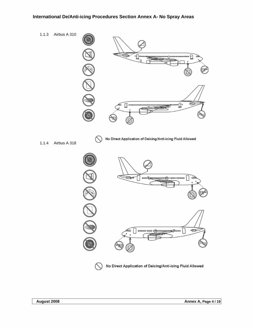
International De/Anti-icing Procedures Section Annex A- No Spray Areas
August 2008 Annex A, Page 4 / 19
1.1.3 Airbus A 310
1.1.4 Airbus A 318
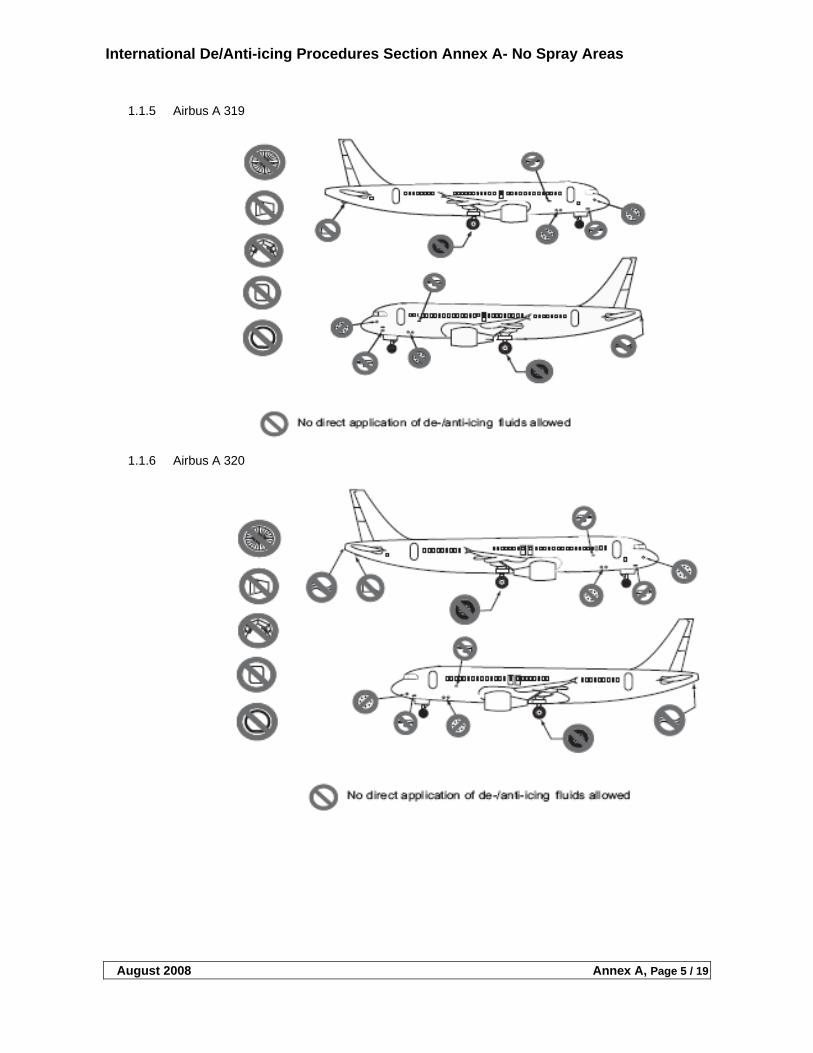
International De/Anti-icing Procedures Section Annex A- No Spray Areas
August 2008 Annex A, Page 5 / 19
1.1.5 Airbus A 319
1.1.6 Airbus A 320
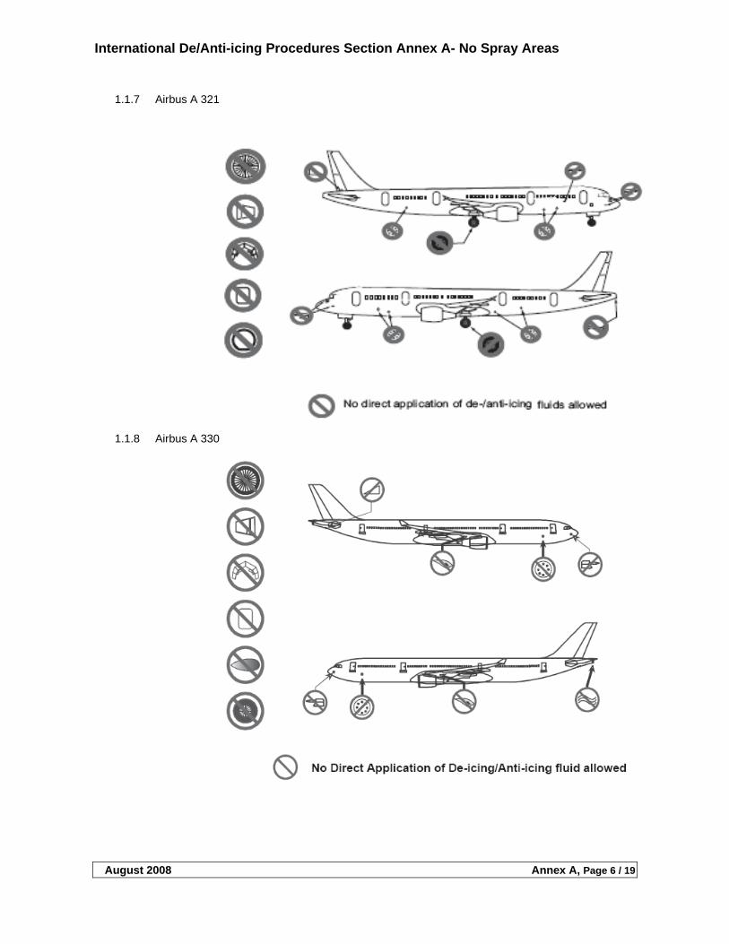
International De/Anti-icing Procedures Section Annex A- No Spray Areas
August 2008 Annex A, Page 6 / 19
1.1.7 Airbus A 321
1.1.8 Airbus A 330
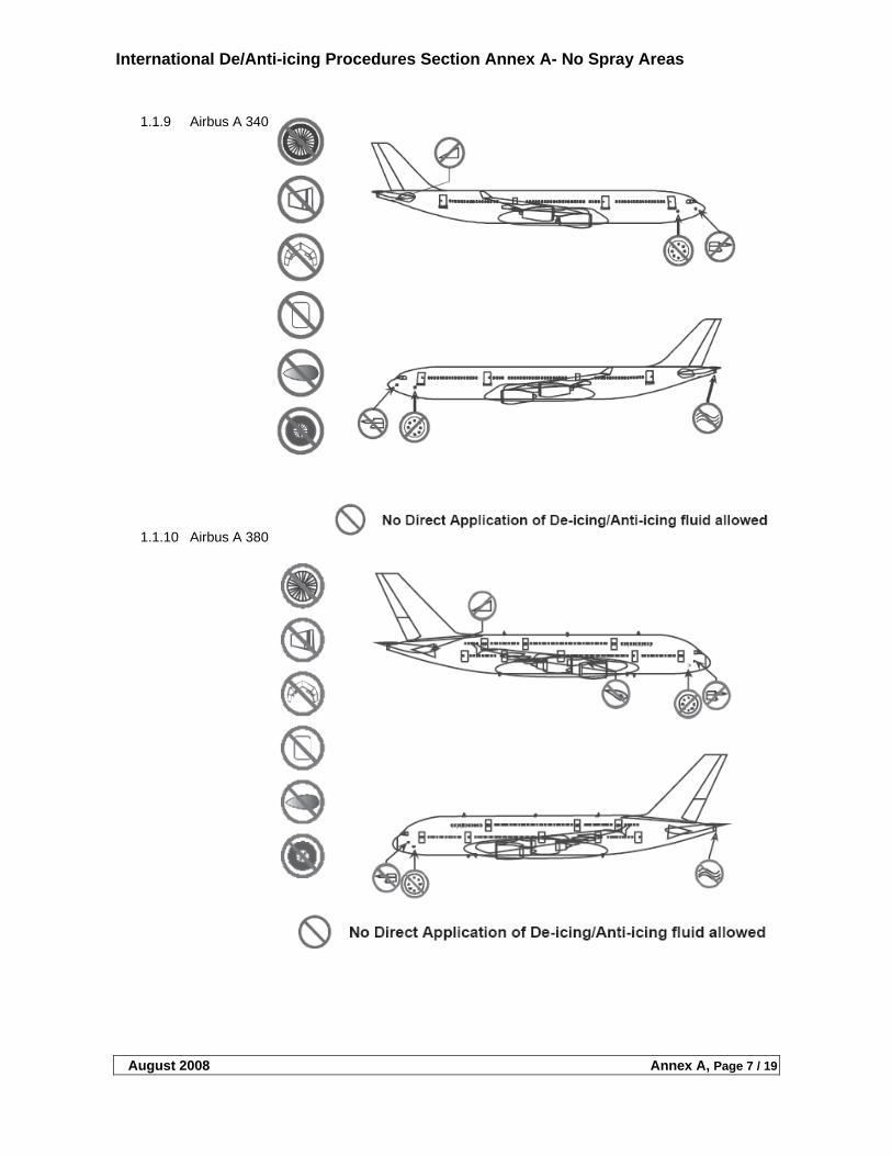
International De/Anti-icing Procedures Section Annex A- No Spray Areas
August 2008 Annex A, Page 7 / 19
1.1.9 Airbus A 340
1.1.10 Airbus A 380
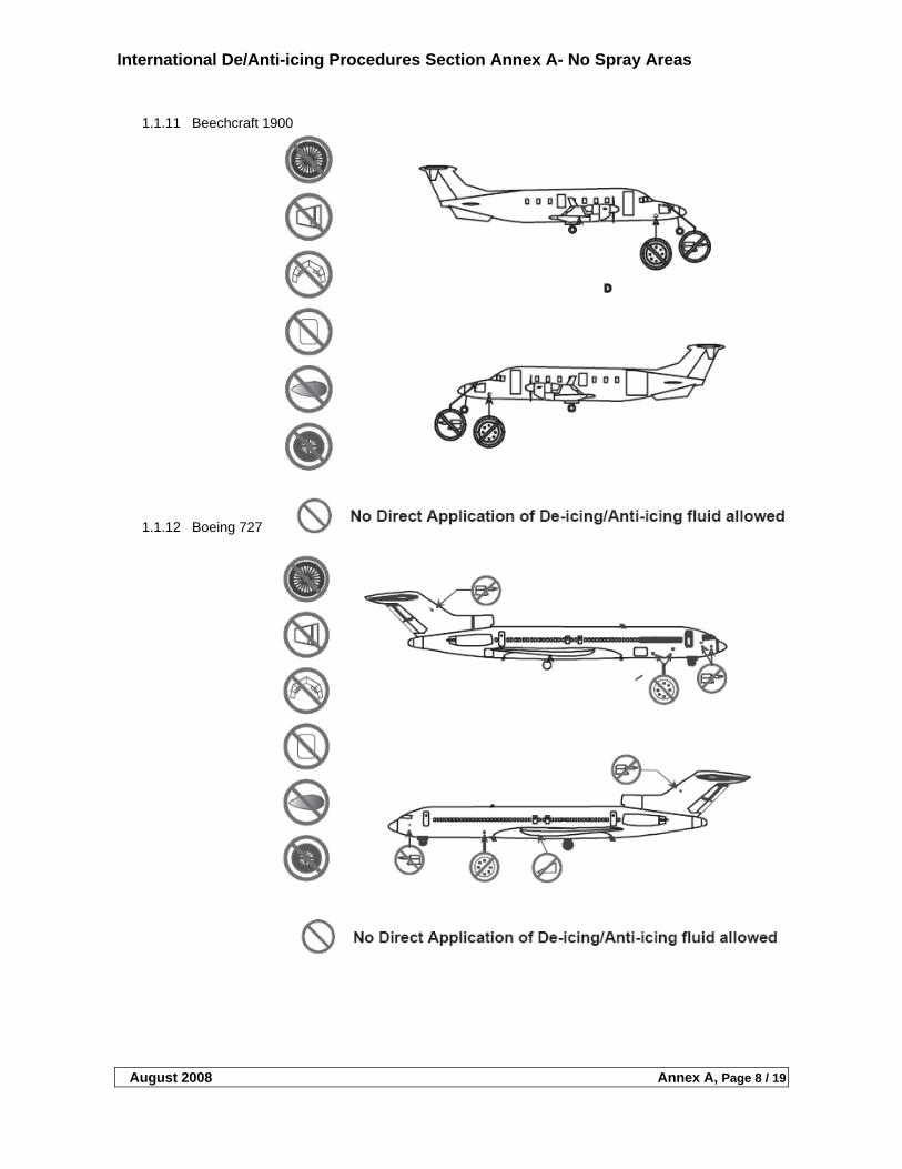
International De/Anti-icing Procedures Section Annex A- No Spray Areas
August 2008 Annex A, Page 8 / 19
1.1.11 Beechcraft 1900
1.1.12 Boeing 727
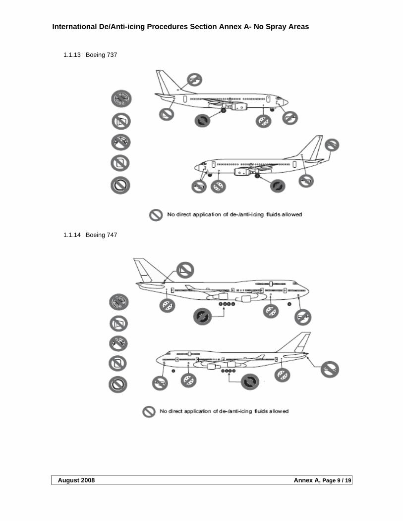
International De/Anti-icing Procedures Section Annex A- No Spray Areas
August 2008 Annex A, Page 9 / 19
1.1.13 Boeing 737
1.1.14 Boeing 747
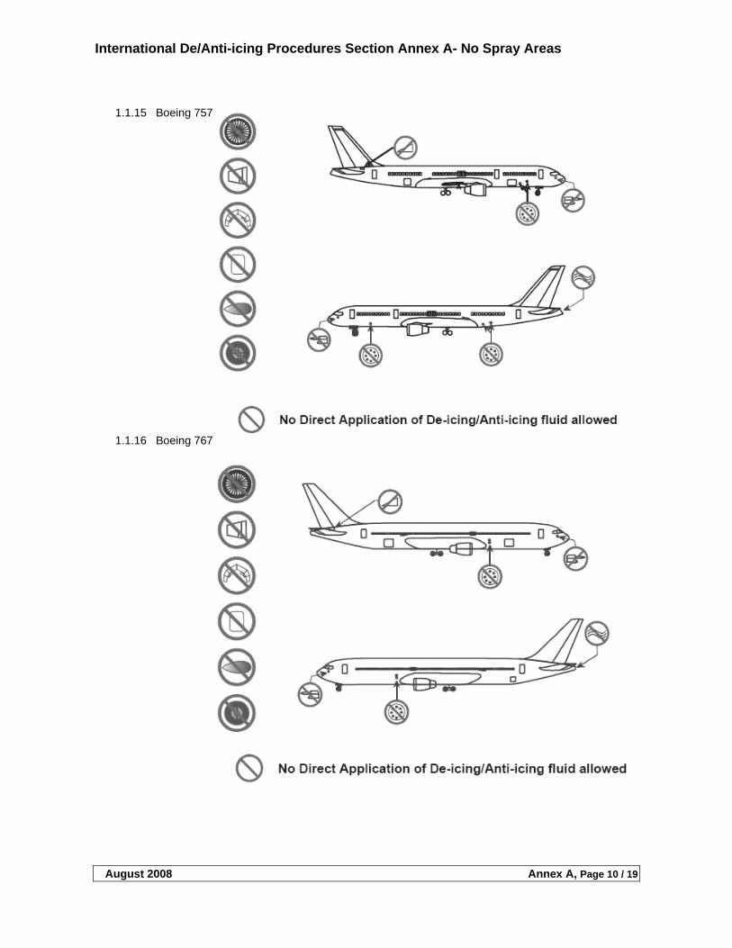
International De/Anti-icing Procedures Section Annex A- No Spray Areas
August 2008 Annex A, Page 10 / 19
1.1.15 Boeing 757
1.1.16 Boeing 767
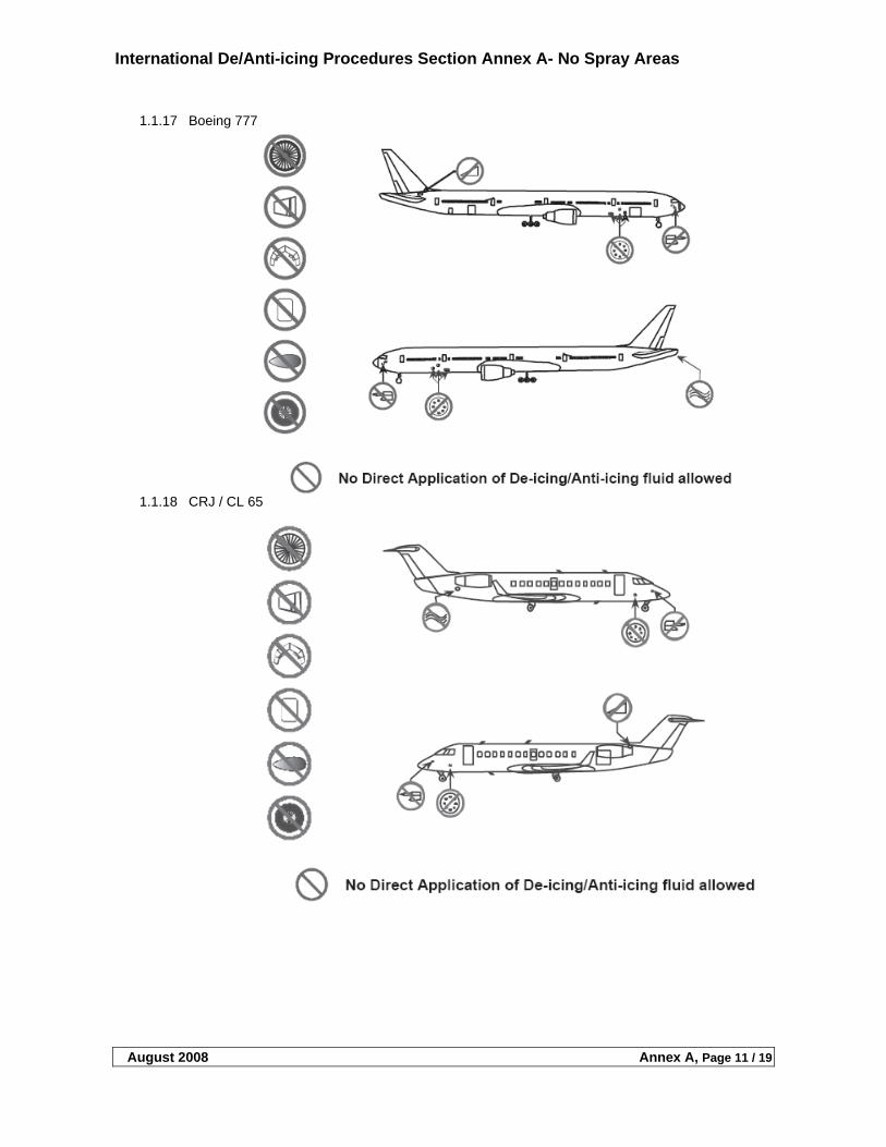
International De/Anti-icing Procedures Section Annex A- No Spray Areas
August 2008 Annex A, Page 11 / 19
1.1.17 Boeing 777
1.1.18 CRJ / CL 65
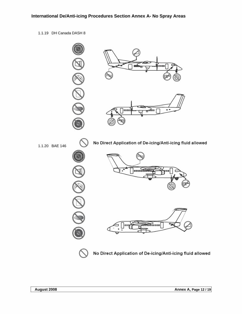
International De/Anti-icing Procedures Section Annex A- No Spray Areas
August 2008 Annex A, Page 12 / 19
1.1.19 DH Canada DASH 8
1.1.20 BAE 146
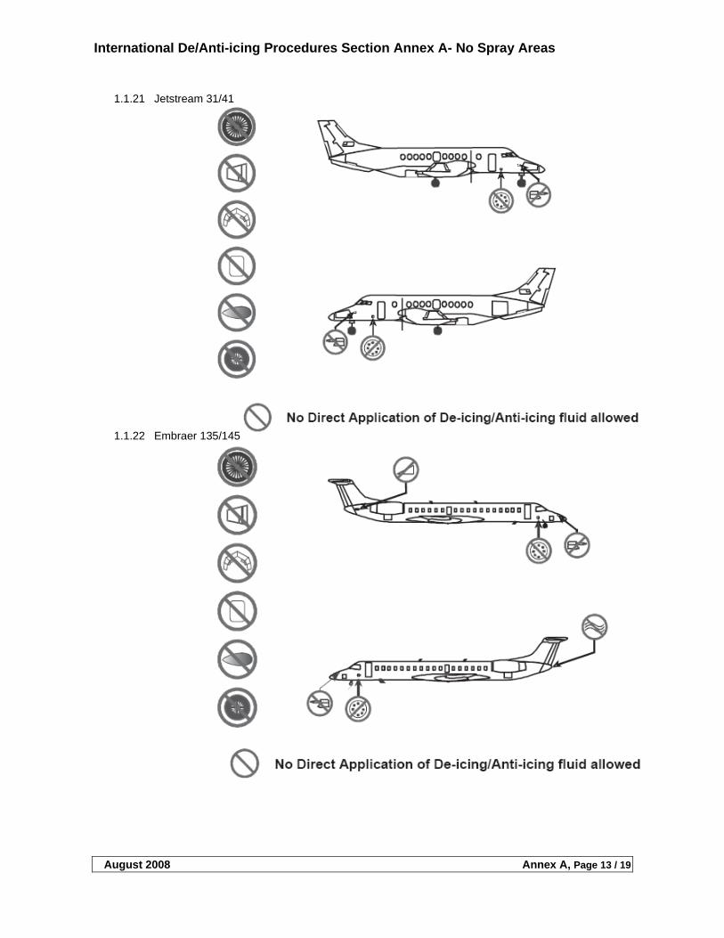
International De/Anti-icing Procedures Section Annex A- No Spray Areas
August 2008 Annex A, Page 13 / 19
1.1.21 Jetstream 31/41
1.1.22 Embraer 135/145
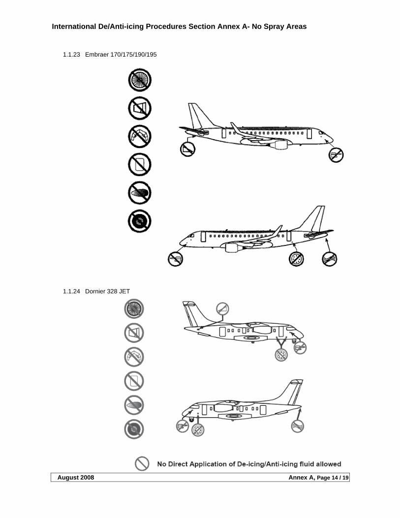
International De/Anti-icing Procedures Section Annex A- No Spray Areas
August 2008 Annex A, Page 14 / 19
1.1.23 Embraer 170/175/190/195
1.1.24 Dornier 328 JET
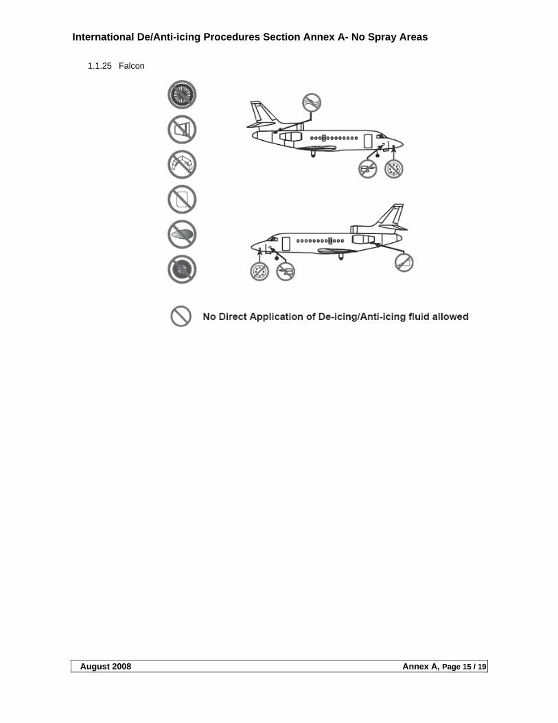
International De/Anti-icing Procedures Section Annex A- No Spray Areas
August 2008 Annex A, Page 15 / 19
1.1.25 Falcon
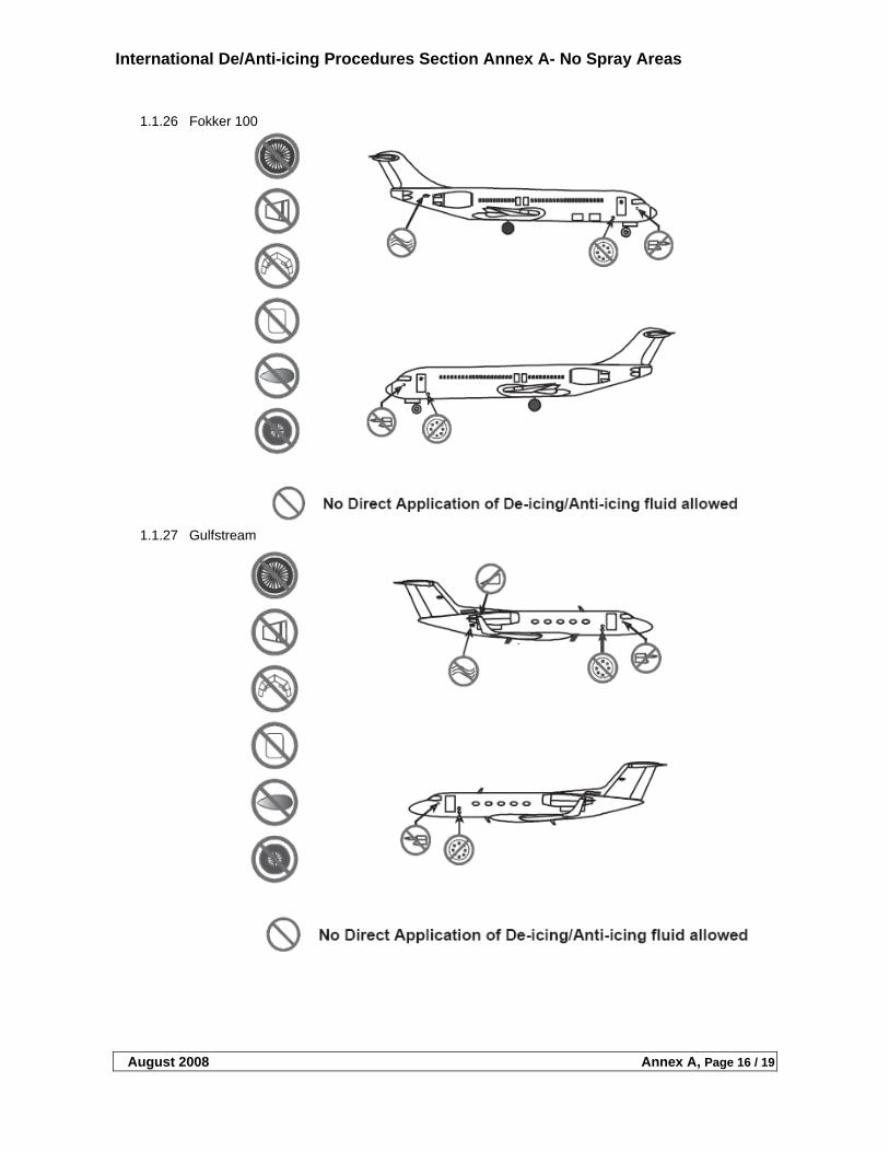
International De/Anti-icing Procedures Section Annex A- No Spray Areas
August 2008 Annex A, Page 16 / 19
1.1.26 Fokker 100
1.1.27 Gulfstream
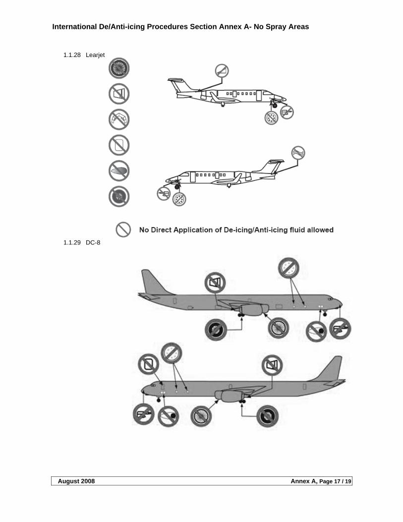
International De/Anti-icing Procedures Section Annex A- No Spray Areas
August 2008 Annex A, Page 17 / 19
1.1.28 Learjet
1.1.29 DC-8
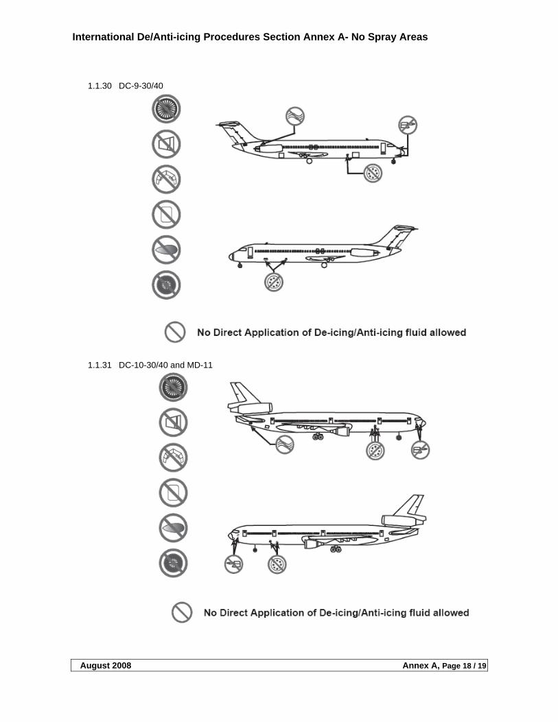
International De/Anti-icing Procedures Section Annex A- No Spray Areas
August 2008 Annex A, Page 18 / 19
1.1.30 DC-9-30/40
1.1.31 DC-10-30/40 and MD-11
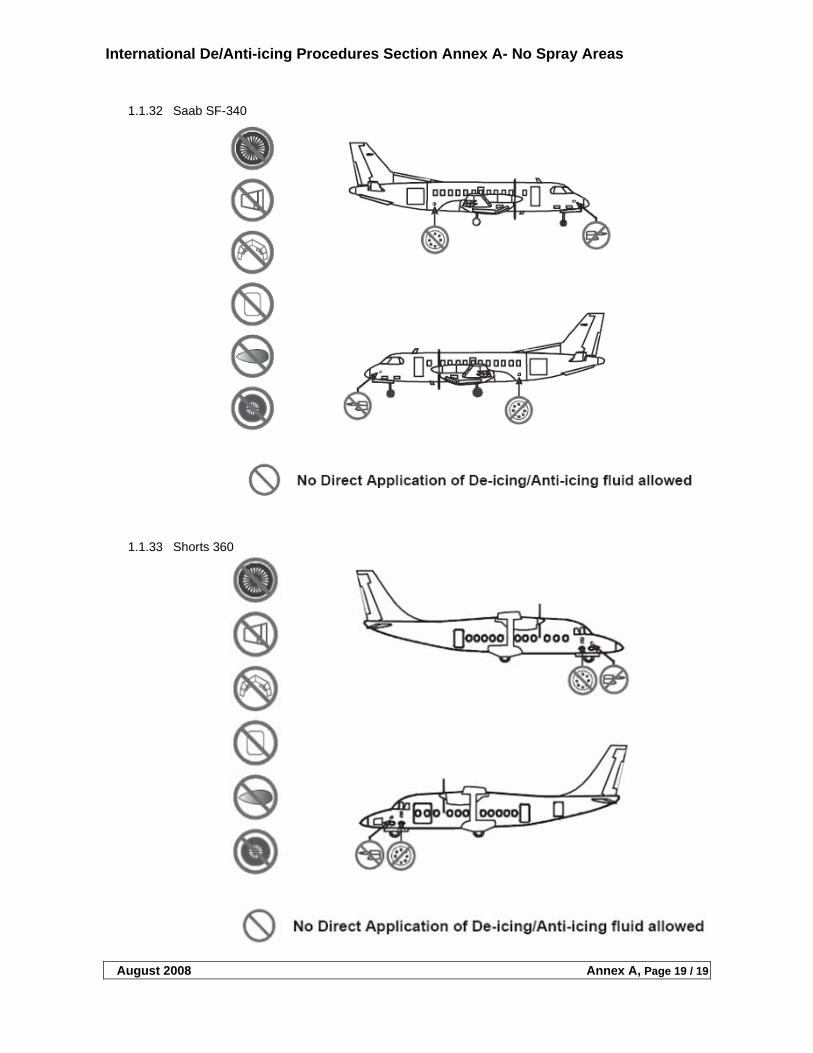
International De/Anti-icing Procedures Section Annex A- No Spray Areas
August 2008 Annex A, Page 19 / 19
1.1.32 Saab SF-340
1.1.33 Shorts 360
International De/Anti-icing Training Section
August 2008 Page 1 of 6
TABLE OF CONTENTS
1 TRAINING................................................................................................................................................................ 2
1.1 TRAINING REQUIREMENTS .........................................................................................................................................2 1.1.1 Testing ...............................................................................................................................................................2 1.1.2 Scope of Training...............................................................................................................................................2 1.1.3 Training Renewal...............................................................................................................................................2 1.1.4 Training Session ................................................................................................................................................3 1.1.5 Quality Assurance..............................................................................................................................................5 1.1.6 Review Plan .......................................................................................................................................................5 1.1.7 Records ..............................................................................................................................................................5
International De/Anti-icing Training Section
August 2008 Page 2 of 6
1 TRAINING
1.1 Training Requirements
Deicing/anti-icing procedure must be carried out exclusively by trained and qualified personnel. For personnel performing the actual deicing/anti-icing treatment on aircraft, practical training with the deicing/anti-icing equipment shall be included.
1.1.1 Testing
Training success shall be proven by exam which shall cover all training subjects contained in section. Pass mark shall be 75% or better corrected to 100%. Only persons passing the exam can be qualified. . The written exam can be performed as an open book exam where pertinent holdover time tables and quality indexes can be referred. Normal deicing procedures should be common knowledge and there should not be any material available during the test explaining these subjects. Note that deicing operations should be based on safety and not based on things remembered (regarding holdover timetables and quality). The examination for any particular course shall be built so that all relevant subjects are covered by the questions. As a rule of thumb, a minimum of one question per subject should be included in the written exam. The minimum amount of questions shall not be less than 15 questions. The questions shall not be misleading. The question series should cover all aspects of operation and include the local arrangements (if any). Practical evaluation should include an oral quizzing where practical items are covered (e.g. reading holdover timetables and/or refractive index limits etc.).
1.1.2 Scope of Training
Both initial and annual recurrent training shall be conducted to ensure that all such crews obtain and retain a thorough knowledge of aircraft ground deicing/anti-icing policies and procedures, including new procedures and lessons learned. New/changed procedures after training is received for the season must also be trained.
1.1.3 Training Renewal
Recurrent training does not have to be performed exactly or before the date of the previous qualification. This would lead to a neverending advancement of training. The qualification will stay valid for the beginning of the next season but needs to be renewed before the years end. As an example: if qualified on November 1st 2007 a renewal is forthcoming in November 2008 but no later than 31st December. This flexibility eases the burdon of training large groups in the beginning of the season. However, it is highly recommended that the training be performed as early in the season (or before the beginning of the season) as practicable.
International De/Anti-icing Training Section
August 2008 Page 3 of 6
1.1.4 Training Session
Ground Personnel must be trained and tested or qualified on at least the subjects identified below. Training subjects shall include but are not limited to (when applicable):
1. Clean Aircraft Concept (effects of frost, ice, snow, and slush on aircraft surfaces). This discussion is intended to provide an understanding of the critical effect the presence of even minute amounts of frost, ice, or snow on flight surfaces and should include, but is not limited to, the following:
(a) Loss of Lift. (b) Increased drag and weight. (c) Decreased control. (d) Aircraft specific areas.
(i) Engine foreign object damage potential. (ii) Ram air intakes. (iii) Instrument pickup points. (iv) Leading edge device (LED) aircraft (aircraft that have slats or leading edge flaps) and non-
LED aircraft.
2. Aircraft Ground Icing Conditions. Describe conditions that cause implementation of deicing/anti-icing procedures.
(a) Frost, including hoarfrost. (b) Freezing Precipitation. Snow, freezing rain, freezing drizzle, or hail which could adhere to aircraft
surfaces. (c) Freezing Fog. (d) Rain or High Humidity on Cold Soaked Wing. (e) Rain or High Humidity on Cold Soaked Wing Fuel Tanks. (f) Underwing Frost. (may not require deicing/anti-icing within certain limits)
3. “Location specific” deicing/anti-icing procedures, including
(a) Health, safety and first aid. (b) Environmental considerations.
4. Communications procedures between the flight crew, ground personnel, ATC, and company station
personnel. Communications with ATC should include coordinating deicing/anti-icing of the aircraft with any proposed ATC push back time and coordinating any other special requirements needed for accomplishing required aircraft checks.
5. Means for obtaining most current weather information.
6. Characteristics and capabilities of fluids utilized: (a) General fluid descriptions. (b) Composition and appearance. (c) Differences between Type I and Type II/III/IV deicing/anti-icing fluids. (d) Purpose for each type. (e) Deicing fluids (f) Anti-icing fluids (g) Deicing/anti-icing fluids capabilities. (h) Approved deicing/anti-icing fluids for use (SAE, ISO, etc.) (i) Fluid specific information provided by fluid or aircraft manufacturer.
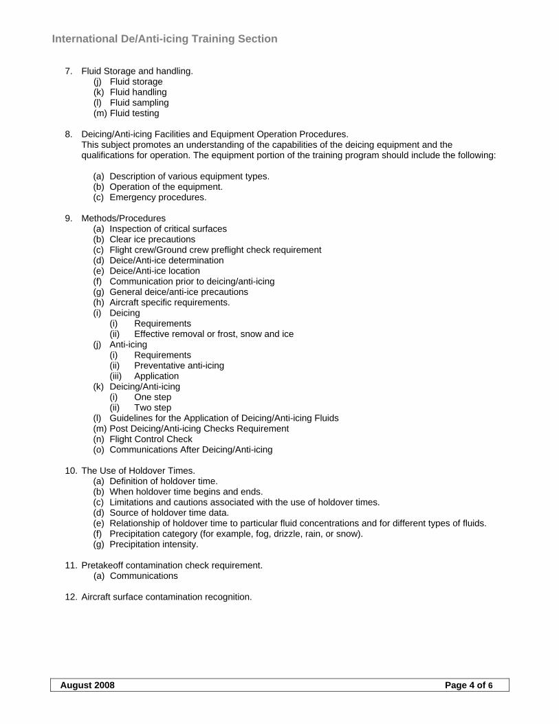
International De/Anti-icing Training Section
August 2008 Page 4 of 6
7. Fluid Storage and handling. (j) Fluid storage (k) Fluid handling (l) Fluid sampling (m) Fluid testing
8. Deicing/Anti-icing Facilities and Equipment Operation Procedures.
This subject promotes an understanding of the capabilities of the deicing equipment and the qualifications for operation. The equipment portion of the training program should include the following:
(a) Description of various equipment types. (b) Operation of the equipment. (c) Emergency procedures.
9. Methods/Procedures
(a) Inspection of critical surfaces (b) Clear ice precautions (c) Flight crew/Ground crew preflight check requirement (d) Deice/Anti-ice determination (e) Deice/Anti-ice location (f) Communication prior to deicing/anti-icing (g) General deice/anti-ice precautions (h) Aircraft specific requirements. (i) Deicing
(i) Requirements (ii) Effective removal or frost, snow and ice
(j) Anti-icing (i) Requirements (ii) Preventative anti-icing (iii) Application
(k) Deicing/Anti-icing (i) One step (ii) Two step
(l) Guidelines for the Application of Deicing/Anti-icing Fluids (m) Post Deicing/Anti-icing Checks Requirement (n) Flight Control Check (o) Communications After Deicing/Anti-icing
10. The Use of Holdover Times.
(a) Definition of holdover time. (b) When holdover time begins and ends. (c) Limitations and cautions associated with the use of holdover times. (d) Source of holdover time data. (e) Relationship of holdover time to particular fluid concentrations and for different types of fluids. (f) Precipitation category (for example, fog, drizzle, rain, or snow). (g) Precipitation intensity.
11. Pretakeoff contamination check requirement. (a) Communications
12. Aircraft surface contamination recognition.
International De/Anti-icing Training Section
August 2008 Page 5 of 6
1.1.5 Quality Assurance
A Quality Assurance Program to monitor and maintain a high level of competence should be in place. See Quality Control Section.
1.1.6 Review Plan
An ongoing review plan is advisable to evaluate the effectiveness of the deicing/anti-icing training received.
1.1.7 Records
The program shall have a tracking system that ensures all required personnel have been satisfactorily trained. Records of personnel training and qualification (see example figure 1) shall be maintained for proof of qualification. The record shall clearly show that instruction has been given and received. Names, dates and the scope of training must be clearly stated. The flow of information, when issuing new/changed procedures after training must be verified so that it reaches all persons involved. A verification system, that the “deicing procedure / bulletin” has been read and understood, shall be established as proof that all personnel have received the information.
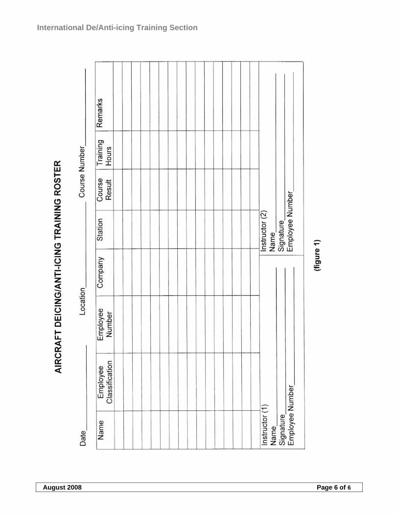
International De/Anti-icing Training Section
August 2008 Page 6 of 6
International De/Anti-icing Training Section Annex B-Teaching Plan
August 2008 Annex B, Page 1 of 20
TABLE OF CONTENTS
1 TRAINING FUNDAMENTALS ................................................................................................................................ 2
1.1 GENERAL ................................................................................................................................................................ 2 1.1.1 The learning process...................................................................................................................................... 2
1.2 THE TEACHING PROCESS ......................................................................................................................................... 2 1.2.1 Teaching methods .......................................................................................................................................... 3 1.2.2 Instructional aids ........................................................................................................................................... 4
1.3 EVALUATION........................................................................................................................................................... 4
2 HOLDOVER TIMETABLE EXAMPLES ............................................................................................................... 5
2.1 TYPE-I..................................................................................................................................................................... 5 2.2 TYPE-II/III/IV......................................................................................................................................................... 5
3 EXAMPLE TEACHING PLAN................................................................................................................................. 7
3.1 SUBJECT .................................................................................................................................................................. 7 3.2 OBJECTIVE .............................................................................................................................................................. 7 3.3 CONTENT ................................................................................................................................................................ 7 3.4 TEACHING AID........................................................................................................................................................ 7 3.5 THEORETICAL ELEMENT......................................................................................................................................... 8 3.6 PRACTICAL ELEMENT ........................................................................................................................................... 13 3.7 ICAO LANGUAGE PROFICIENCY RATING SCALE, MANUAL ON THE IMPLEMENTATION OF ICAO
LANGUAGE PROFICIENCY REQUIREMENTS", 9835, INTERNATIONAL CIVIL AVIATION ORGANIZATION (2004).............. 17 3.8 TYPICAL DE-ANTI-ICING VEHICLE LAYOUT .......................................................................................................... 18
International De/Anti-icing Training Section Annex B-Teaching Plan
August 2008 Annex B, Page 2 of 20
1 TRAINING FUNDAMENTALS
1.1 General
This section is intended as a guide for instructors who are responsible for deicing training (either theoretical or practical), producing material and evaluating training processes. It is important that instructors use this chapter to develop training programs. Deicing operations as a ground service may seem less important to emphasise but this attitude should not be taken. Deicing operations have a direct impact on the safety of the flight and the instruction should make this point very clear in all areas of the process. The new de-icers are all adults and the teaching process should be directed to such an audience with variable backgrounds in life. The instructor should show consistency in teaching, instil high standards for the process, detect unsafe habits and correct them, show professionalism and knowledge of the subject. If the trainer is not interested in the subject then the student will not take the process seriously. Even if the operational side may seem easy and manageable at first hand a knowledge of relevant items is needed to clarify the “what, why and how” of the whole process. The main purpose in education is to help the de-icer translate facts and knowledge into action.
1.1.1 The learning process
Each student sees a learning situation from a different perspective. Learning is an individual process. Knowledge cannot be poured into the student’s head, the student can learn from individual experiences. It is clear enough that the learning of a physical skill requires actual experience in performing that skill. Do not assume that something once told will be remembered instantly. The theoretical aspect needs “practice and drill” to be effectively learned. The subjects must be taught right at the first instance because it is much harder to “unteach” (wrong habits) than to teach new. Normal individuals aquire about 75% of their knowledge through the sense of sight, 13% through hearing and 6% through touch (additionally smell and taste). It can be seen that when teaching something that the student can see, hear and touch (theoretical + practical training) most of the learning process is covered. There is no room for trial and error in deicing operations. It is therefore a major responsibility for the instructor to organise demonstrations and explanations, and to direct student practice, so that the learner has better opportunities to understand the interrelationship of the many kinds of experiences that have been perceived. Adults tend to have their own idea of many processes since they may have previous experiences in many related work areas. It must be clear from the beginning that there can not be any improvising when it comes to safety of deicing operations. When the student is motivated to learn and has the opportunity to perform the skill learned, then it will become an understanding process of theory and practice which is linked together. The deicing/anti-icing training is an annual process. Every refresher training should naturally include the changed procedures but also a refresher of basic operational issues should be covered. Even if the deicing crew have some practical experience over the years, forgetting basic procedures is normal. That is why things not often used or covered in training are usually things that are forgotten and should therefore be repeated in refresher training. It is also important to give meaningful examples for these issues so it would be easier to remember and adapt the knowledge in practice whenever needed.
1.2 The teaching process
The instructor should prepare each instructional session according to the level of the deicing qualifications. All aspects may be relevant to cover but few issues can be more important for one group when some other issues can be important for another group. The training should be specific and not taught as a general subject. After the preparation a presentation of the deicing procedure should be performed in a manner that the students can remember the procedures in practical application. The review and evaluation of procedures are performed with theoretical tests and practical assesments where applicable. A review and evaluation in any case is recommended because it is the only way to make sure that no misconceptions of the deicing operations are remembered. There are some elements that need to be noted when teaching deicing operations for a group with different background knowledge of aviation procedures (if any experience at all). The main thing is to have a good
International De/Anti-icing Training Section Annex B-Teaching Plan
August 2008 Annex B, Page 3 of 20
arrangement of material and procedures to be taught. The student should not have to find out procedures for themselves in basic training. Some issues to remember is to keep the students motivated, informed and present all information consistently. It is important to identify mistakes and review the related issue to correct any misconceptions. The instructor should remember to admit errors in teaching instead of trying to improvise if he/she does not remember. Related elements that are doubtful can be clarified later. Good human relations promote more effective learning. English is not the native language in many cases even though much of the material available is in English. It is the responsibility of the head of deicing instructing to make available any relevant material. This material can be in any native language but the reference must be explained and covered in training. Not only deicing procedure material should be delivered but all pertinent information that have something to do with the whole deicing operation (e.g. airport regulations, winter programs, customer requirements etc.). All material should be distributed in basic training. Students in refresher training should receive all new information but basic material should be available concentratedly for easy access. There is often more than one instructor teaching the procedures and an instructor briefing is recommended to be kept in order to clarify who and what is to be taught by whom (and related material).
1.2.1 Teaching methods
There are several ways to conduct deicing training. The instructional session depends on the group at hand. Deicing procedures are usually presented in a “lecture method”, which is not always the most productive way. There are many elements that simply are not possible to teach in another way but the interest of the group must be established. The lesson should be organised in an introduction, development and conclusion. The students must be made aware of their responsibility and develop a receptive attitude towards the subject. The appearance and attitude of the instructor towards the subject is important when giving students the first indication of the importance of deicing. The introduction should get the students attention, motivate them and give an overview of the area to be covered. In short, the introduction sets the stage for learning. When developing the lesson the instructor must logically organise the material to show the relationships between the main points. There are many subjects that need to be explained, that may not seem relevant at first, for an understanding of how deicing operations reflect these elements. Meaningful transitions from one point to another keep the students oriented and helps them understand how each issue relates to the deicing procedures. Examples of real cases are often used and it has a good effect for showing “what if” scenarious. It is important to focus on the main deicing procedures when concluding the training to give a brief overview of the operation. An effective conclusion retraces the important elements of the lesson and relates them to the objective. Alternative methods to “lectures” can be an illustrated talk where the instructor, with the help of visual aids, reflect the idea to the listeners. Depending on the size of the group a guided discussion method may be used. This method of instructing involves the students more but the student should have some knowledge of the subject in order to make the lessons productive. Some subjects can be taught by demonstration-performance methods (such as ice/frost formation, refractive index tests etc.) and this technique can give a healthy change for the theoretical part. Case studies can also be used for some subjects (such as vehicle incidents, A/C icing etc.) to cover lessons learned and get a brief discussion of the importance of deicing. Human Factors are an important element of the training since case studies may give an valuable insight into the real operation that may perhaps otherwise be overlooked. However, most of the subjects are necessary to be explained in a lecture method but the lecture can be more effective with visual aids (pictures, films etc.). Teaching instructors may be easier in the sense that they have previous knowledge and the emphasis can be set on issues more important and relevant for their particular operation. It is important to cover the basic ideas of correct deicing operation and set standards according to which all procedures are to be followed. After reviewing new and changed issues a discussion of deicing procedures within the group may be a good way of retrieving information on how each person sees a particular procedure. It may be that information of correct deicing procedures has changed down the line in large companies when instructors train others. All misconceptions must be corrected and emphasis on approved procedures shall be made. This can also be the case when teaching subcontractors and their trainers. The problem may be that there is not as good a control of proceedings within a subcontracted company as in the main company. It is important that the
International De/Anti-icing Training Section Annex B-Teaching Plan
August 2008 Annex B, Page 4 of 20
correct procedures are understood and the training elements are covered, for subcontractor trainers, since there may not be any further control of instruction.
1.2.2 Instructional aids
Instructional aids should be used when teaching deicing subjects because the material is in large provided as a lecture. Getting and holding students attention is essential to learning. The use of any instructional aids should be planned and fit in for a specific subject. Pictures, films, examples and relating tools can be used. Note that there are many old films and pictures for deicing operations and their use is not recommended unless they still cover the subject correctly. Computer based training and presentation is a modern way of teaching any subject and it also gets the students attention. Computers are not available everywhere and deicing programs are not either but traditional teaching aids can be as successful when used correctly. The instructor should perform an overview of the material before distributing or showing the relating subject material. It must be clear what the film or printed material contains in order to explain it correctly. This is especially so when using material that is not originating from within the company. There is a large amount of relating material available for deicing, standards and recommendations, vehicle and A/C documentation, videos etc., and the material should not be unfamiliar to the presenter as it may be to the student. Instead of simply distributing the material an explanation of the content should be made. Computer based instruction must be presented in a manner that is understandable for the student. If ”self-study” programs are available for deicing then a briefing should be held over the subjects so the content is correctly read and understood. Cbt-programs can be a helpful aid to reinforce something already presented. Any additional study program can also be harmful if English is the instructional language but the student lacks sufficient understanding of all terms and directions. Whenever using copied material, videos, cbt-programs etc., it must be made clear what are current procedures and what is for reference only.
1.3 Evaluation
Evaluating the deicing training is one last process where misconceptions can still be corrected. It is very important that the evaluation benefits the student as well as the deicing operation. Theoretical evaluation is performed with exams and practical evaluation can be performed by an assessment of operation. It must be clear in the beginning that the whole deicing process contains an evaluation process. This may motivate the students to be more active towards the subjects. The evaluation does not benefit safety when it is introduced by surprise. The training program must contain procedures of training and evaluation. The evaluation process must be taken into account when building up the time schedule for training. Note that a good debriefing can clear up misconceptions better than simply failing or approving students. The ultimate goal of the whole training is to produce a safe deicing operation.
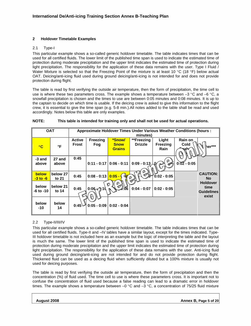
International De/Anti-icing Training Section Annex B-Teaching Plan
August 2008 Annex B, Page 5 of 20
2 Holdover Timetable Examples
2.1 Type-I
This particular example shows a so-called generic holdover timetable. The table indicates times that can be used for all certified fluids. The lower limit of the published time span is used to indicate the estimated time of protection during moderate precipitation and the upper limit indicates the estimated time of protection during light precipitation. The responsibility for the application of these data remains with the user. Type I Fluid / Water Mixture is selected so that the Freezing Point of the mixture is at least 10 C (18 F) below actual OAT. Deicing/anti-icing fluid used during ground deicing/anti-icing is not intended for and does not provide protection during flight. The table is read by first verifying the outside air temperature, then the form of precipitation, the time cell to use is where these two parameters cross. The example shows a temperature between –3 C and –6 C, a snowfall precipitation is chosen and the times to use are between 0:05 minutes and 0:08 minutes. It is up to the captain to decide on which time is usable. If the deicing crew is asked to give this information to the flight crew, it is essential to give the time span (e.g. 5-8 min.).All notes added to the table shall be read and used accordingly. Notes below this table are only examples. NOTE: This table is intended for training only and shall not be used for actual operations.
OAT Approximate Holdover Times Under Various Weather Conditions (hours : minutes)
C °F
Active Frost
Freezing Fog
*Snow/ Snow Grains
**Freezing Drizzle
Light Freezing
Rain
Rain on Cold
Soaked Wing
Other***
-3 and above
27 and above
0:45 0:11 - 0:17 0:06 - 0:11 0:09 - 0:13 0:02 - 0:05 0:02 - 0:05
below -3 to -6
below 27 to 21
0:45 0:08 - 0:13 0:05 - 0:08 0:05 - 0:09 0:02 - 0:05
below -6 to -10
below 21 to 14
0:45 0:06 - 0:10 0:04 - 0:06 0:04 - 0:07 0:02 - 0:05
below -10
below 14
0:45 0:05 - 0:09 0:02 - 0:04
CAUTION:No
Holdover time
Guidelines exist
2.2 Type-II/III/IV
This particular example shows a so-called generic holdover timetable. The table indicates times that can be used for all certified fluids. Type-II and –IV tables have a similar layout, except for the times indicated. Type-III holdover timetable is not included here as an example but the logic of interpreting the table and the layout is much the same. The lower limit of the published time span is used to indicate the estimated time of protection during moderate precipitation and the upper limit indicates the estimated time of protection during light precipitation. The responsibility for the application of these data remains with the user. Anti-icing fluid used during ground deicing/anti-icing are not intended for and do not provide protection during flight. Thickened fluid can be used as a deicing fluid when sufficiently diluted but a 100% mixture is usually not used for deicing purposes. The table is read by first verifying the outside air temperature, then the form of precipitation and then the concentration (%) of fluid used. The time cell to use is where these parameters cross. It is important not to confuse the concentration of fluid used because a false reading can lead to a dramatic error in holdover times. The example shows a temperature between –0 C and –3 C, a concentration of 75/25 fluid mixture
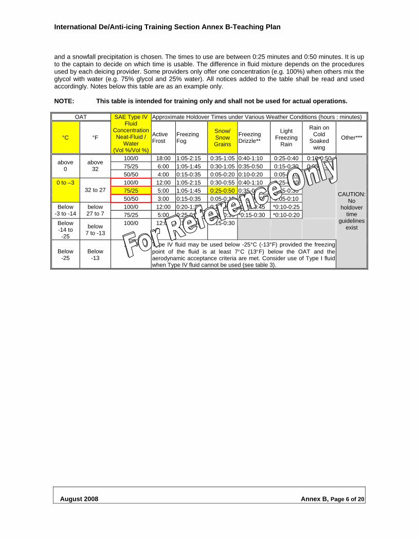
International De/Anti-icing Training Section Annex B-Teaching Plan
August 2008 Annex B, Page 6 of 20
and a snowfall precipitation is chosen. The times to use are between 0:25 minutes and 0:50 minutes. It is up to the captain to decide on which time is usable. The difference in fluid mixture depends on the procedures used by each deicing provider. Some providers only offer one concentration (e.g. 100%) when others mix the glycol with water (e.g. 75% glycol and 25% water). All notices added to the table shall be read and used accordingly. Notes below this table are as an example only. NOTE: This table is intended for training only and shall not be used for actual operations.
OAT Approximate Holdover Times under Various Weather Conditions (hours : minutes)
°C °F
SAE Type IV Fluid
Concentration Neat-Fluid /
Water (Vol %/Vol %)
Active Frost
Freezing Fog
Snow/ Snow Grains
Freezing Drizzle**
Light Freezing
Rain
Rain on Cold
Soaked wing
Other***
100/0 18:00 1:05-2:15 0:35-1:05 0:40-1:10 0:25-0:40 0:10-0:50
75/25 6:00 1:05-1:45 0:30-1:05 0:35-0:50 0:15-0:30 0:05-0:35 above
0 above
32 50/50 4:00 0:15-0:35 0:05-0:20 0:10-0:20 0:05-0:10
100/0 12:00 1:05-2:15 0:30-0:55 0:40-1:10 0:25-0:40
75/25 5:00 1:05-1:45 0:25-0:50 0:35-0:50 0:15-0:30
0 to –3 32 to 27
50/50 3:00 0:15-0:35 0:05-0:15 0:10-0:20 0:05-0:10
100/0 12:00 0:20-1:20 0:20-0:40 *0:20-0:45 *0:10-0:25 Below -3 to -14
below 27 to 7 75/25 5:00 0:25-0:50 0:20-0:35 *0:15-0:30 *0:10-0:20
Below -14 to
-25
below 7 to -13
100/0 12:00 0:15-0:40 0:15-0:30
Below -25
Below -13
100/0 Type IV fluid may be used below -25°C (-13°F) provided the freezing point of the fluid is at least 7C (13F) below the OAT and the aerodynamic acceptance criteria are met. Consider use of Type I fluid when Type IV fluid cannot be used (see table 3).
CAUTION:No
holdover time
guidelinesexist
International De/Anti-icing Training Section Annex B-Teaching Plan
August 2008 Annex B, Page 7 of 20
3 Example Teaching Plan
The following pages contain an example Teaching Plan (TP). The TP is the guide to deicing/anti-icing training and includes all of the required minimum elements to include in the training session, as detailed in the Deicing / Anti-icing Training Recommendations. The TP is in two parts, part 1 covers the theoretical elements of training and part 2 covers the practical training. The TP is designed to be a high level guide from which individual, detailed lesson plans can be developed, and should be used for both initial and refresher training. The TP is made up as follows:
3.1 Subject
This column contains all of the main subject headers that should be included in all deicing / anti-icing training. The TP represents what is required by stations to train in order to meet US Airways standards for deicing / anti-icing aircraft.
3.2 Objective
This column is self-explanatory and indicates the aims of the training.
3.3 Content
This column represents the minimum subject content of each main subject heading.
3.4 Teaching Aid
Items shown in this column are only representative of what can be used as a teaching aid; they do not represent a minimum requirement. It is accepted that for the station, to substitute the use of an aircraft for practical training purposes, with other simulated means. Some examples of how this can be accomplished include, firstly, ‘use cones to mark out the shape of an aircraft on the ground’. This can be invaluable when practicing driving around an aircraft. Secondly, in the absence of an aircraft for spraying practice, a flat bed truck or a row of empty baggage containers could be used to simulate a wing surface.
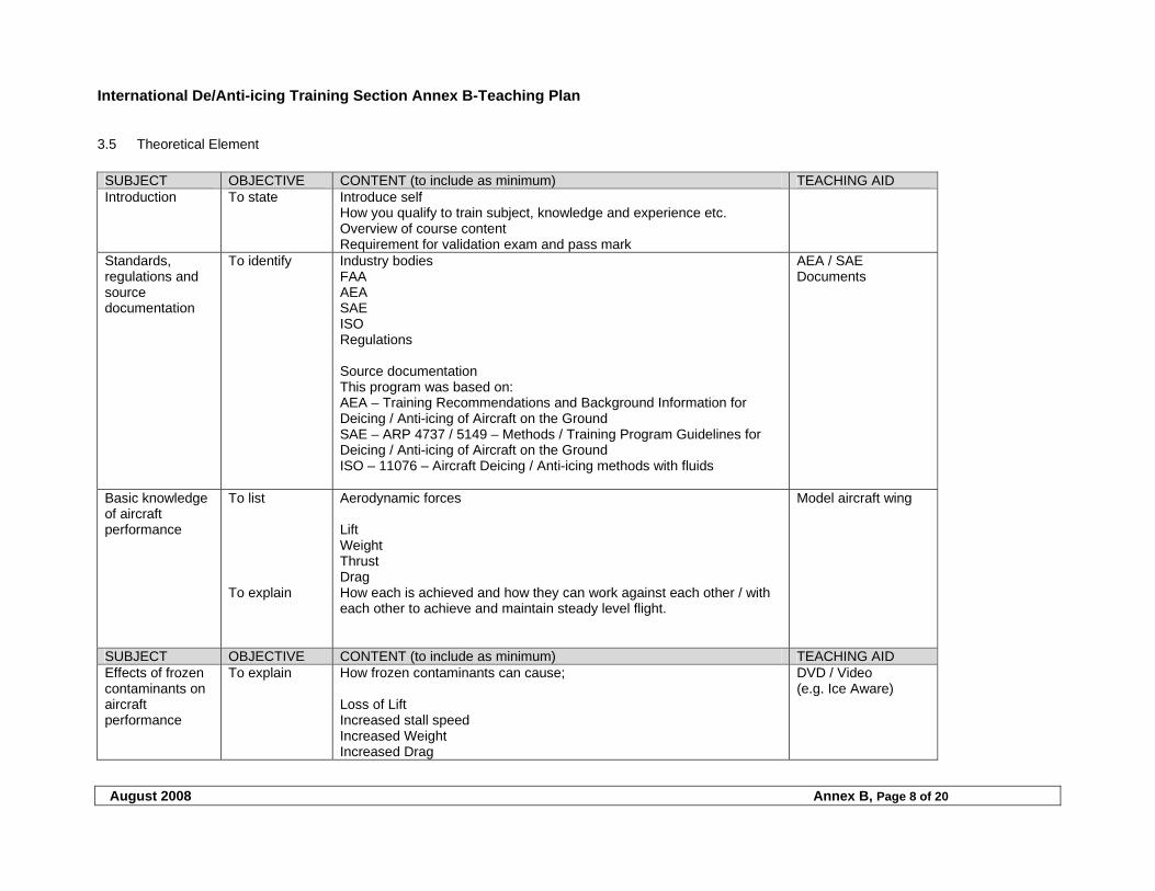
International De/Anti-icing Training Section Annex B-Teaching Plan
August 2008 Annex B, Page 8 of 20
3.5 Theoretical Element
SUBJECT OBJECTIVE CONTENT (to include as minimum) TEACHING AID Introduction To state Introduce self
How you qualify to train subject, knowledge and experience etc. Overview of course content Requirement for validation exam and pass mark
Standards, regulations and source documentation
To identify Industry bodies FAA AEA SAE ISO Regulations Source documentation This program was based on: AEA – Training Recommendations and Background Information for Deicing / Anti-icing of Aircraft on the Ground SAE – ARP 4737 / 5149 – Methods / Training Program Guidelines for Deicing / Anti-icing of Aircraft on the Ground ISO – 11076 – Aircraft Deicing / Anti-icing methods with fluids
AEA / SAE Documents
Basic knowledge of aircraft performance
To list To explain
Aerodynamic forces Lift Weight Thrust Drag How each is achieved and how they can work against each other / with each other to achieve and maintain steady level flight.
Model aircraft wing
SUBJECT OBJECTIVE CONTENT (to include as minimum) TEACHING AID Effects of frozen contaminants on aircraft performance
To explain How frozen contaminants can cause; Loss of Lift Increased stall speed Increased Weight Increased Drag
DVD / Video (e.g. Ice Aware)
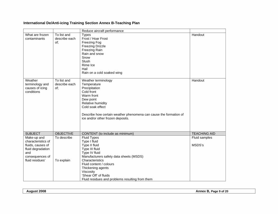
International De/Anti-icing Training Section Annex B-Teaching Plan
August 2008 Annex B, Page 9 of 20
Reduce aircraft performance What are frozen contaminants
To list and describe each of;
Types Frost / Hoar Frost Freezing Fog Freezing Drizzle Freezing Rain Rain and snow Snow Slush Rime Ice Hail Rain on a cold soaked wing
Handout
Weather terminology and causes of icing conditions
To list and describe each of;
Weather terminology Temperature Precipitation Cold front Warm front Dew point Relative humidity Cold soak effect Describe how certain weather phenomena can cause the formation of ice and/or other frozen deposits.
Handout
SUBJECT OBJECTIVE CONTENT (to include as minimum) TEACHING AID Make-up and characteristics of fluids, causes of fluid degradation and consequences of fluid residues’
To describe To explain
Fluid Types Type I fluid Type II fluid Type III fluid Type IV fluid Manufacturers safety data sheets (MSDS) Characteristics Fluid content / colours Thickening agents Viscosity ‘Shear Off’ of fluids Fluid residues and problems resulting from them
Fluid samples MSDS’s
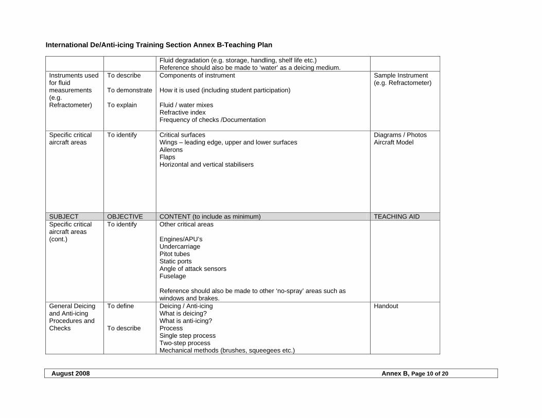
International De/Anti-icing Training Section Annex B-Teaching Plan
August 2008 Annex B, Page 10 of 20
Fluid degradation (e.g. storage, handling, shelf life etc.) Reference should also be made to ‘water’ as a deicing medium.
Instruments used for fluid measurements (e.g. Refractometer)
To describe To demonstrate To explain
Components of instrument How it is used (including student participation) Fluid / water mixes Refractive index Frequency of checks /Documentation
Sample Instrument (e.g. Refractometer)
Specific critical aircraft areas
To identify
Critical surfaces Wings – leading edge, upper and lower surfaces Ailerons Flaps Horizontal and vertical stabilisers
Diagrams / Photos Aircraft Model
SUBJECT OBJECTIVE CONTENT (to include as minimum) TEACHING AID Specific critical aircraft areas (cont.)
To identify Other critical areas Engines/APU’s Undercarriage Pitot tubes Static ports Angle of attack sensors Fuselage Reference should also be made to other ‘no-spray’ areas such as windows and brakes.
General Deicing and Anti-icing Procedures and Checks
To define To describe
Deicing / Anti-icing What is deicing? What is anti-icing? Process Single step process Two-step process Mechanical methods (brushes, squeegees etc.)
Handout
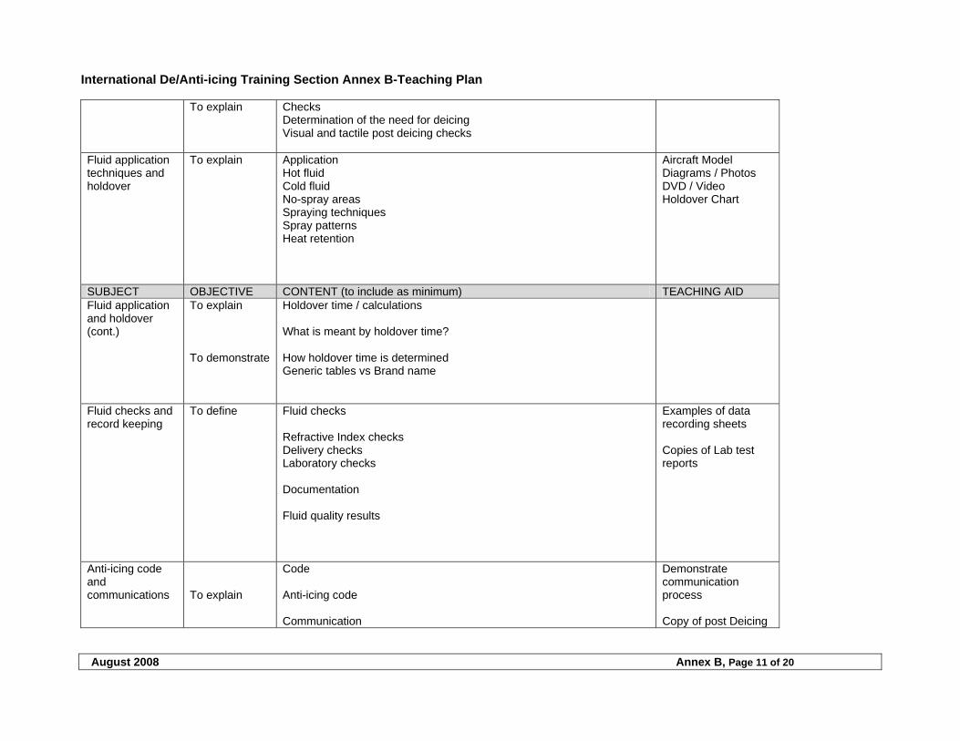
International De/Anti-icing Training Section Annex B-Teaching Plan
August 2008 Annex B, Page 11 of 20
To explain Checks Determination of the need for deicing Visual and tactile post deicing checks
Fluid application techniques and holdover
To explain Application Hot fluid Cold fluid No-spray areas Spraying techniques Spray patterns Heat retention
Aircraft Model Diagrams / Photos DVD / Video Holdover Chart
SUBJECT OBJECTIVE CONTENT (to include as minimum) TEACHING AID Fluid application and holdover (cont.)
To explain To demonstrate
Holdover time / calculations What is meant by holdover time? How holdover time is determined Generic tables vs Brand name
Fluid checks and record keeping
To define Fluid checks Refractive Index checks Delivery checks Laboratory checks Documentation Fluid quality results
Examples of data recording sheets Copies of Lab test reports
Anti-icing code and communications
To explain
Code Anti-icing code Communication
Demonstrate communication process Copy of post Deicing
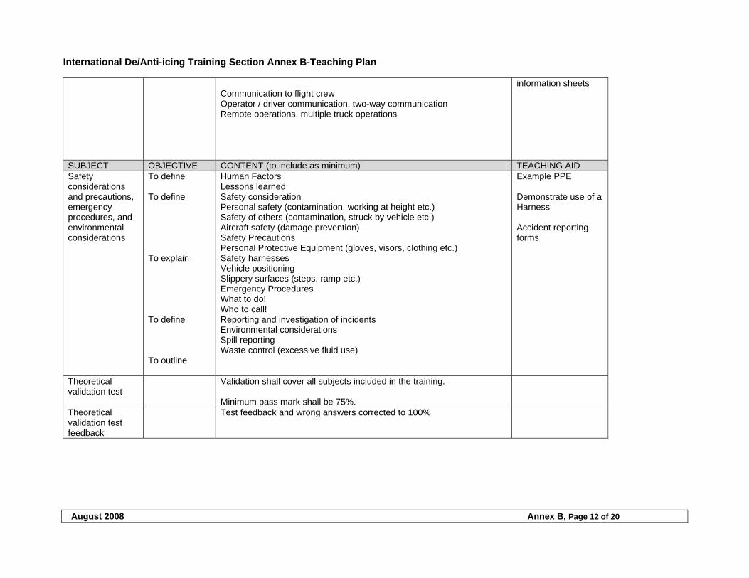
International De/Anti-icing Training Section Annex B-Teaching Plan
August 2008 Annex B, Page 12 of 20
Communication to flight crew Operator / driver communication, two-way communication Remote operations, multiple truck operations
information sheets
SUBJECT OBJECTIVE CONTENT (to include as minimum) TEACHING AID Safety considerations and precautions, emergency procedures, and environmental considerations
To define To define To explain To define To outline
Human Factors Lessons learned Safety consideration Personal safety (contamination, working at height etc.) Safety of others (contamination, struck by vehicle etc.) Aircraft safety (damage prevention) Safety Precautions Personal Protective Equipment (gloves, visors, clothing etc.) Safety harnesses Vehicle positioning Slippery surfaces (steps, ramp etc.) Emergency Procedures What to do! Who to call! Reporting and investigation of incidents Environmental considerations Spill reporting Waste control (excessive fluid use)
Example PPE Demonstrate use of a Harness Accident reporting forms
Theoretical validation test
Validation shall cover all subjects included in the training. Minimum pass mark shall be 75%.
Theoretical validation test feedback
Test feedback and wrong answers corrected to 100%
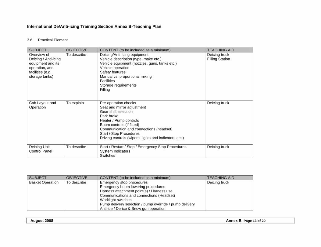
International De/Anti-icing Training Section Annex B-Teaching Plan
August 2008 Annex B, Page 13 of 20
3.6 Practical Element
SUBJECT OBJECTIVE CONTENT (to be included as a minimum) TEACHING AID Overview of Deicing / Anti-icing equipment and its operation, and facilities (e.g. storage tanks)
To describe Deicing/Anti-Icing equipment Vehicle description (type, make etc.) Vehicle equipment (nozzles, guns, tanks etc.) Vehicle operation Safety features Manual vs. proportional mixing Facilities Storage requirements Filling
Deicing truck Filling Station
Cab Layout and Operation
To explain Pre-operation checks Seat and mirror adjustment Gear shift selection Park brake Heater / Pump controls Boom controls (if fitted) Communication and connections (headset) Start / Stop Procedures Driving controls (wipers, lights and indicators etc.)
Deicing truck
Deicing Unit Control Panel
To describe Start / Restart / Stop / Emergency Stop Procedures System Indicators Switches
Deicing truck
SUBJECT OBJECTIVE CONTENT (to be included as a minimum) TEACHING AID Basket Operation To describe
Emergency stop procedures Emergency boom lowering procedures Harness attachment point(s) / Harness use Communications and connections (Headset) Worklight switches Pump delivery selection / pump override / pump delivery Anti-ice / De-ice & Snow gun operation
Deicing truck
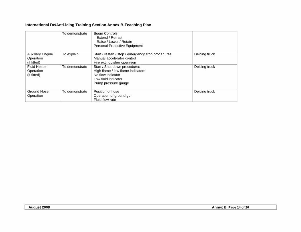
International De/Anti-icing Training Section Annex B-Teaching Plan
August 2008 Annex B, Page 14 of 20
To demonstrate Boom Controls Extend / Retract Raise / Lower / Rotate Personal Protective Equipment
Auxiliary Engine Operation (if fitted)
To explain Start / restart / stop / emergency stop procedures Manual accelerator control Fire extinguisher operation
Deicing truck
Fluid Heater Operation (if fitted)
To demonstrate Start / Shut down procedures High flame / low flame indicators No flow indicator Low fluid indicator Pump pressure gauge
Deicing truck
Ground Hose Operation
To demonstrate Position of hose Operation of ground gun Fluid flow rate
Deicing truck
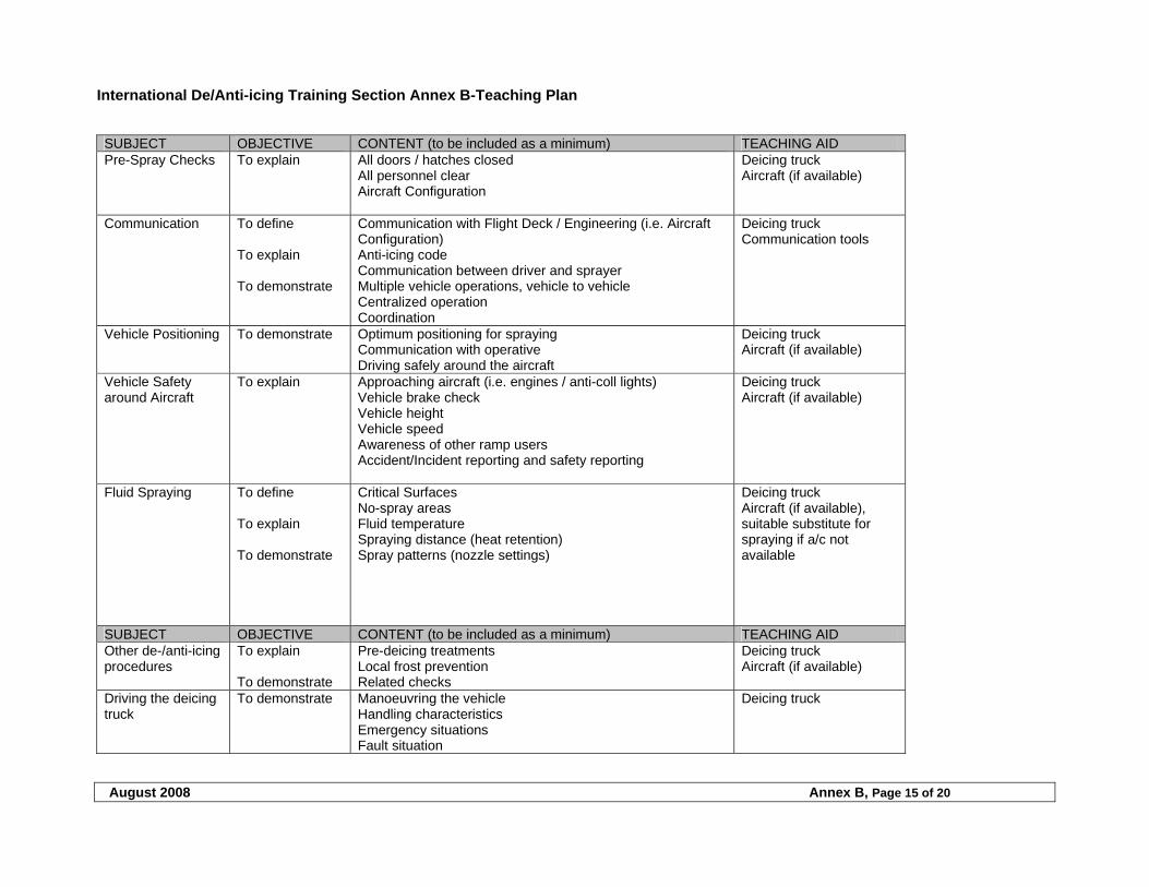
International De/Anti-icing Training Section Annex B-Teaching Plan
August 2008 Annex B, Page 15 of 20
SUBJECT OBJECTIVE CONTENT (to be included as a minimum) TEACHING AID Pre-Spray Checks To explain All doors / hatches closed
All personnel clear Aircraft Configuration
Deicing truck Aircraft (if available)
Communication To define To explain To demonstrate
Communication with Flight Deck / Engineering (i.e. Aircraft Configuration) Anti-icing code Communication between driver and sprayer Multiple vehicle operations, vehicle to vehicle Centralized operation Coordination
Deicing truck Communication tools
Vehicle Positioning To demonstrate Optimum positioning for spraying Communication with operative Driving safely around the aircraft
Deicing truck Aircraft (if available)
Vehicle Safety around Aircraft
To explain Approaching aircraft (i.e. engines / anti-coll lights) Vehicle brake check Vehicle height Vehicle speed Awareness of other ramp users Accident/Incident reporting and safety reporting
Deicing truck Aircraft (if available)
Fluid Spraying To define To explain To demonstrate
Critical Surfaces No-spray areas Fluid temperature Spraying distance (heat retention) Spray patterns (nozzle settings)
Deicing truck Aircraft (if available), suitable substitute for spraying if a/c not available
SUBJECT OBJECTIVE CONTENT (to be included as a minimum) TEACHING AID Other de-/anti-icing procedures
To explain To demonstrate
Pre-deicing treatments Local frost prevention Related checks
Deicing truck Aircraft (if available)
Driving the deicing truck
To demonstrate Manoeuvring the vehicle Handling characteristics Emergency situations Fault situation
Deicing truck
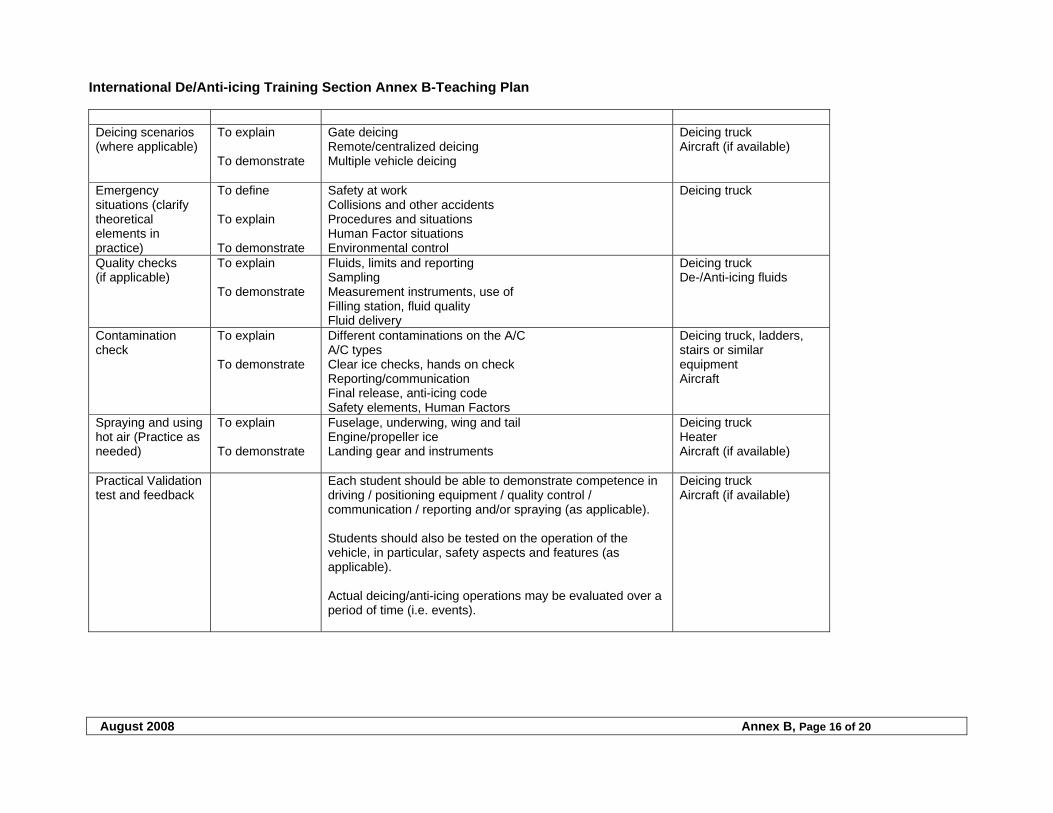
International De/Anti-icing Training Section Annex B-Teaching Plan
August 2008 Annex B, Page 16 of 20
Deicing scenarios (where applicable)
To explain To demonstrate
Gate deicing Remote/centralized deicing Multiple vehicle deicing
Deicing truck Aircraft (if available)
Emergency situations (clarify theoretical elements in practice)
To define To explain To demonstrate
Safety at work Collisions and other accidents Procedures and situations Human Factor situations Environmental control
Deicing truck
Quality checks (if applicable)
To explain To demonstrate
Fluids, limits and reporting Sampling Measurement instruments, use of Filling station, fluid quality Fluid delivery
Deicing truck De-/Anti-icing fluids
Contamination check
To explain To demonstrate
Different contaminations on the A/C A/C types Clear ice checks, hands on check Reporting/communication Final release, anti-icing code Safety elements, Human Factors
Deicing truck, ladders, stairs or similar equipment Aircraft
Spraying and using hot air (Practice as needed)
To explain To demonstrate
Fuselage, underwing, wing and tail Engine/propeller ice Landing gear and instruments
Deicing truck Heater Aircraft (if available)
Practical Validation test and feedback
Each student should be able to demonstrate competence in driving / positioning equipment / quality control / communication / reporting and/or spraying (as applicable). Students should also be tested on the operation of the vehicle, in particular, safety aspects and features (as applicable). Actual deicing/anti-icing operations may be evaluated over a period of time (i.e. events).
Deicing truck Aircraft (if available)
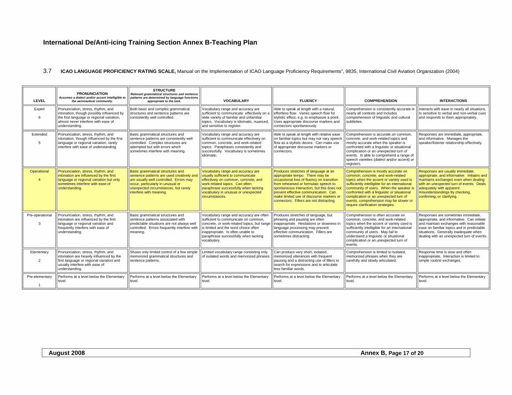
International De/Anti-icing Training Section Annex B-Teaching Plan
August 2008 Annex B, Page 17 of 20
3.7 ICAO LANGUAGE PROFICIENCY RATING SCALE, Manual on the Implementation of ICAO Language Proficiency Requirements", 9835, International Civil Aviation Organization (2004)
LEVEL
PRONUNCIATION Assumes a dialect and/or accent intelligible to
the aeronautical community.
STRUCTURE Relevant grammatical structures and sentence patterns are determined by language functions
appropriate to the task. VOCABULARY FLUENCY COMPREHENSION INTERACTIONS
Expert 6
Pronunciation, stress, rhythm, and intonation, though possibly influenced by the first language or regional variation, almost never interfere with ease of understanding.
Both basic and complex grammatical structures and sentence patterns are consistently well controlled.
Vocabulary range and accuracy are sufficient to communicate effectively on a wide variety of familiar and unfamiliar topics. Vocabulary is idiomatic, nuanced, and sensitive to register.
Able to speak at length with a natural, effortless flow. Varies speech flow for stylistic effect, e.g. to emphasize a point. Uses appropriate discourse markers and connectors spontaneously.
Comprehension is consistently accurate in nearly all contexts and includes comprehension of linguistic and cultural subtleties.
Interacts with ease in nearly all situations. Is sensitive to verbal and non-verbal cues and responds to them appropriately.
Extended 5
Pronunciation, stress, rhythm, and intonation, though influenced by the first language or regional variation, rarely interfere with ease of understanding.
Basic grammatical structures and sentence patterns are consistently well controlled. Complex structures are attempted but with errors which sometimes interfere with meaning.
Vocabulary range and accuracy are sufficient to communicate effectively on common, concrete, and work-related topics. Paraphases consistently and successfully. Vocabulary is sometimes idiomatic.
Able to speak at length with relative ease on familiar topics but may not vary speech flow as a stylistic device. Can make use of appropriate discourse markers or connectors.
Comprehension is accurate on common, concrete, and work-related topics and mostly accurate when the speaker is confronted with a linguistic or situational complication or an unexpected turn of events. Is able to comprehend a range of speech varieties (dialect and/or accent) or registers.
Responses are immediate, appropriate, and informative. Manages the speaker/listener relationship effectively.
Operational 4
Pronunciation, stress, rhythm, and intonation are influenced by the first language or regional variation but only sometimes interfere with ease of understanding.
Basic grammatical structures and sentence patterns are used creatively and are usually well controlled. Errors may occur, particularly in unusual or unexpected circumstances, but rarely interfere with meaning.
Vocabulary range and accuracy are usually sufficient to communicate effectively on common, concrete, and work-related topics. Can often paraphrase successfully when lacking vocabulary in unusual or unexpected circumstances.
Produces stretches of language at an appropriate tempo. There may be occassional loss of fluency on transition from rehearsed or formulaic speech to spontaneous interaction, but this does not prevent effective communication. Can make limited use of discourse markers or connectors. Fillers are not distracting.
Comprehension is mostly accurate on common, concrete, and work-related topics when the accent or variety used is sufficiently intelligible for an international community of users. When the speaker is confronted with a linguistic or situational complication or an unexpected turn of events, comprehension may be slower or require clarification strategies.
Responses are usually immediate, appropriate, and informative. Initiates and maintains exchanges even when dealing with an unexpected turn of events. Deals adequately with apparent misunderstandings by checking, confirming, or clarifying.
Pre-operational 3
Pronunciation, stress, rhythm, and intonation are influenced by the first language or regional variation and frequently interfere with ease of understanding.
Basic grammatical structures and sentence patterns associated with predictable situations are not always well controlled. Errors frequently interfere with meaning.
Vocabulary range and accuracy are often sufficient to communicate on common, concrete, or work-related topics, but range is limited and the word choice often inappropriate. Is often unable to paraphrase successfully when lacking vocabulary.
Produces stretches of language, but phrasing and pausing are often inappropriate. Hesitations or slowness in language processing may prevent effective communication. Fillers are sometimes distracting.
Comprehension is often accurate on common, concrete, and work-related topics when the accent or variety used is sufficiently intelligible for an international community of users. May fail to understand a linguistic or situational complication or an unexpected turn of events.
Responses are sometimes immediate, appropriate, and informative. Can initiate and maintain exchanges with reasonable ease on familiar topics and in predictable situations. Generally inadequate when dealing with an unexpected turn of events.
Elementary 2
Pronunciation, stress, rhythm, and intonation are heavily influenced by the first language or regional variation and usually interfere with ease of understanding.
Shows only limited control of a few simple memorized grammatical structures and sentence patterns.
Limited vocabulary range consisting only of isolated words and memorized phrases.
Can produce very short, isolated, memorized utterances with frequent pausing and a distracting use of fillers to search for expressions and to articulate less familiar words.
Comprehension is limited to isolated, memorized phrases when they are carefully and slowly articulated.
Response time is slow and often inappropriate. Interaction is limited to simple routine exchanges.
Pre-elementary 1
Performs at a level below the Elementary level.
Performs at a level below the Elementary level.
Performs at a level below the Elementary level.
Performs at a level below the Elementary level.
Performs at a level below the Elementary level.
Performs at a level below the Elementary level.
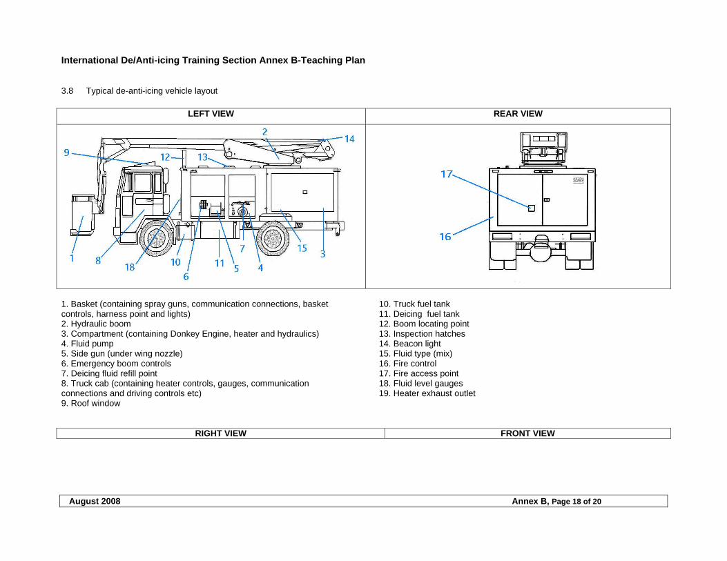
International De/Anti-icing Training Section Annex B-Teaching Plan
August 2008 Annex B, Page 18 of 20
3.8 Typical de-anti-icing vehicle layout
LEFT VIEW REAR VIEW
1. Basket (containing spray guns, communication connections, basket controls, harness point and lights) 2. Hydraulic boom 3. Compartment (containing Donkey Engine, heater and hydraulics) 4. Fluid pump 5. Side gun (under wing nozzle) 6. Emergency boom controls 7. Deicing fluid refill point 8. Truck cab (containing heater controls, gauges, communication connections and driving controls etc) 9. Roof window
10. Truck fuel tank 11. Deicing fuel tank 12. Boom locating point 13. Inspection hatches 14. Beacon light 15. Fluid type (mix) 16. Fire control 17. Fire access point 18. Fluid level gauges 19. Heater exhaust outlet
RIGHT VIEW FRONT VIEW
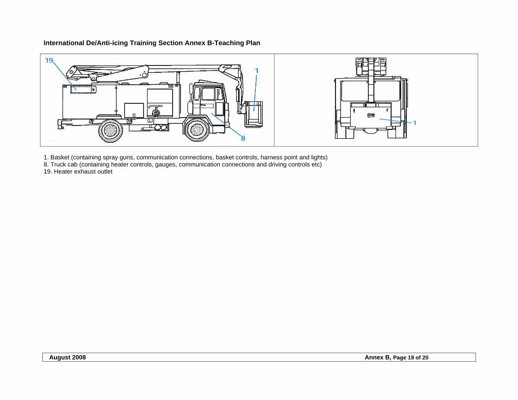
International De/Anti-icing Training Section Annex B-Teaching Plan
August 2008 Annex B, Page 19 of 20
1. Basket (containing spray guns, communication connections, basket controls, harness point and lights) 8. Truck cab (containing heater controls, gauges, communication connections and driving controls etc) 19. Heater exhaust outlet
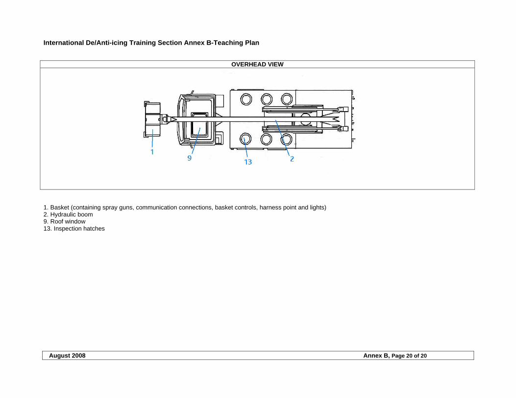
International De/Anti-icing Training Section Annex B-Teaching Plan
August 2008 Annex B, Page 20 of 20
OVERHEAD VIEW
1. Basket (containing spray guns, communication connections, basket controls, harness point and lights) 2. Hydraulic boom 9. Roof window 13. Inspection hatches
International De/Anti-icing Quality Control Section
August 2008 Page 1 of 19
TABLE OF CONTENTS
1 QUALITY CONTROL ............................................................................................................................................ 2
1.1 DE/ANTI-ICING QUALITY PROGRAM ...........................................................................................................................2 1.2 QUALITY CONTROL.....................................................................................................................................................2
1.2.1 Quality of training .............................................................................................................................................2 1.2.2 Quality of operation...........................................................................................................................................2
2 DEVA CHECKLISTS............................................................................................................................................ 19
International De/Anti-icing Quality Control Section
August 2008 Page 2 of 19
1 QUALITY CONTROL
1.1 De/Anti-icing quality program
The De/ Anti-icing Vendor Audit (DEVA) will be used to audit international stations.
1.2 Quality control
Prior to the start of new operations and prior to the start of the current de/ anti-icing season a complete DEVA Check shall be conducted by a FAA 121 Air Carrier designated representative in compliance with the company’s Quality Assurance Program. A DEVA Checklist shall be completed after each audit and copies of this report distributed to the responsible person at each station. Ensure that all negative responses are actioned within the time scale annotated in the checklist. Then complete, distribute and place in this chapter updated copies of the checklist. A determination will be made if the station can de/anti-ice the carrier’s aircraft before corrective actions are approved and implemented. The station shall maintain vehicles/equipment, fluids, training, qualifications and procedures, in accordance with this approved chapter. Personnel carrying out the deicing/anti-icing operation, and the person responsible for final release/dispatch of the aircraft are responsible for ensuring that the task is performed in accordance with this chapter.
1.2.1 Quality of training
Deicing/anti-icing procedures shall only be performed by trained and qualified persons. Material used shall be of the latest edition of any relevant subject. Material used for reference or training only shall be marked accordingly. Manuals used shall be of the latest edition and a system of revision shall be established with the company concerned. Training subjects shall include those mentioned in the Training Section of this chapter. Both initial and annual training is required, including practical training where applicable. The quality program includes an area of monitoring training success and the effectiveness of deicing/anti-icing training received. A periodical review of the training will be accomplished. Training must be recorded in a manner that is easily retrievable by responsible persons involved. Records shall be available at all stations (or retrievable) for proof of qualification.
1.2.2 Quality of operation
In addition to the annual DEVA Checklist audit, a station quality control of daily operations shall be performed. This inspection is an internal quality assurance to assure the safety and effectiveness of operation for both the staff and the customer. The inspection shall include at least the following areas: a) Inspection of the vehicle and relating equipment b) Inspection of filling station and relevant systems c) Daily checks and records d) Performance of all deicing/anti-icing related areas e) Safety issues and special situations f) Personnel and clothing/safety gear f) Communication procedures g) Delivery of fluids and quality checks/procedures h) Records of deicing/anti-icing events i) Inspection of the local management plan The inspection (or auditing) of the operation is only one indication at a particular time on how procedures are established and followed. The Station’s Quality Control should check on how standardised the procedures are and how they are understood. The idea is to observe how the published requirements and procedures are conducted and how the required standard is achieved. The inspection (or audit) needs to be observed as an impartial reflection on the organizational procedures. The quality control should give indications on how the operation could be further developed. Meetings should be held with customers and representatives in order to improve or correct the deicing/anti-icing operation.
International De/Anti-icing Quality Control Section
August 2008 Page 3 of 19
Many standards and recommendations are available for deicing/anti-icing. Different regions refer to some documentation when others refer to other documentation. The procedures do not differ dramatically between these documents but there are slight changes. All deicing procedures used must comply with this manual.
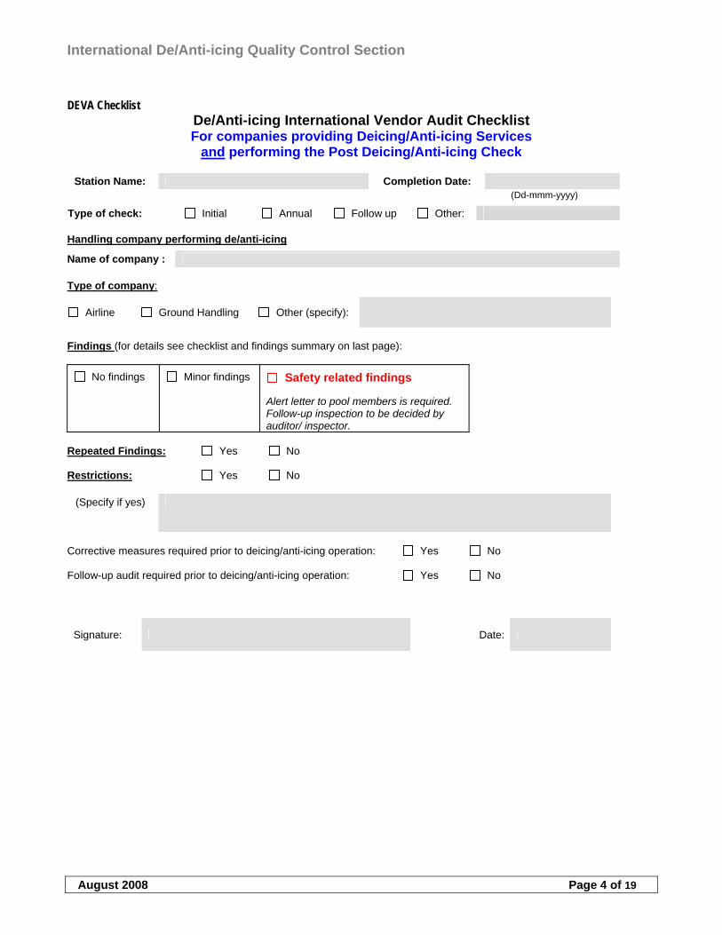
International De/Anti-icing Quality Control Section
August 2008 Page 4 of 19
DEVA Checklist
De/Anti-icing International Vendor Audit Checklist For companies providing Deicing/Anti-icing Services
and performing the Post Deicing/Anti-icing Check
Station Name: Completion Date: (Dd-mmm-yyyy)
Type of check: Initial Annual Follow up Other: Handling company performing de/anti-icing
Name of company : Type of company:
Airline Ground Handling Other (specify):
Findings (for details see checklist and findings summary on last page):
No findings
Minor findings
Safety related findings Alert letter to pool members is required. Follow-up inspection to be decided by auditor/ inspector.
Repeated Findings: Yes No Restrictions: Yes No
(Specify if yes)
Corrective measures required prior to deicing/anti-icing operation: Yes No Follow-up audit required prior to deicing/anti-icing operation: Yes No
Signature: Date:
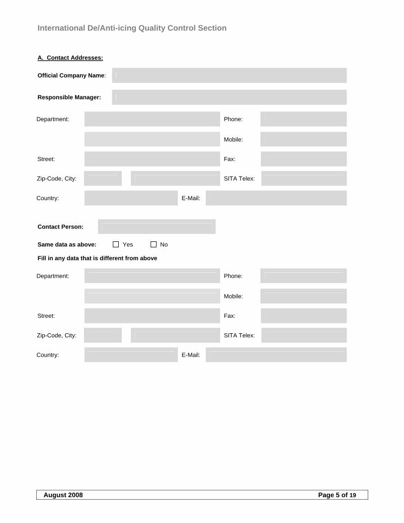
International De/Anti-icing Quality Control Section
August 2008 Page 5 of 19
A. Contact Addresses:
Official Company Name:
Responsible Manager:
Department: Phone:
Mobile:
Street: Fax:
Zip-Code, City: SITA Telex:
Country: E-Mail:
Contact Person:
Same data as above: Yes No Fill in any data that is different from above
Department: Phone:
Mobile:
Street: Fax:
Zip-Code, City: SITA Telex:
Country: E-Mail:
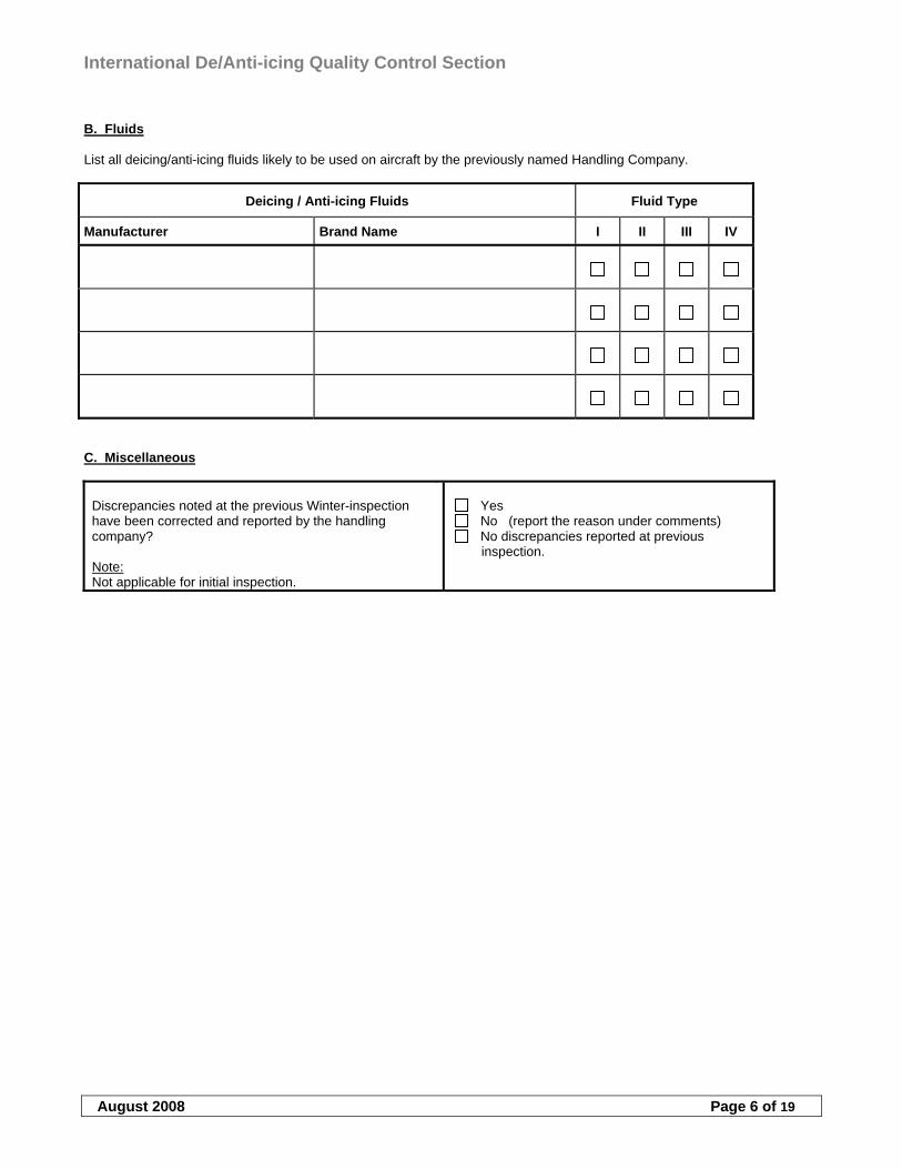
International De/Anti-icing Quality Control Section
August 2008 Page 6 of 19
B. Fluids List all deicing/anti-icing fluids likely to be used on aircraft by the previously named Handling Company.
Deicing / Anti-icing Fluids Fluid Type
Manufacturer Brand Name I II III IV
C. Miscellaneous
Discrepancies noted at the previous Winter-inspection have been corrected and reported by the handling company? Note: Not applicable for initial inspection.
Yes No (report the reason under comments) No discrepancies reported at previous
inspection.
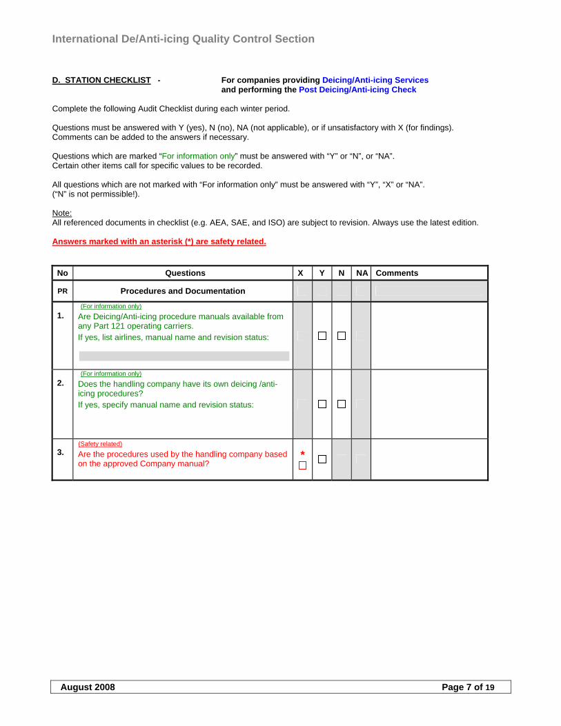
International De/Anti-icing Quality Control Section
August 2008 Page 7 of 19
D. STATION CHECKLIST - For companies providing Deicing/Anti-icing Services and performing the Post Deicing/Anti-icing Check
Complete the following Audit Checklist during each winter period. Questions must be answered with Y (yes), N (no), NA (not applicable), or if unsatisfactory with X (for findings). Comments can be added to the answers if necessary. Questions which are marked “For information only” must be answered with “Y” or “N”, or “NA”. Certain other items call for specific values to be recorded. All questions which are not marked with “For information only” must be answered with “Y”, “X” or “NA”. (“N” is not permissible!). Note: All referenced documents in checklist (e.g. AEA, SAE, and ISO) are subject to revision. Always use the latest edition. Answers marked with an asterisk (*) are safety related.
No Questions X Y N NA Comments
PR Procedures and Documentation
1.
(For information only)
Are Deicing/Anti-icing procedure manuals available from any Part 121 operating carriers. If yes, list airlines, manual name and revision status:
2. (For information only)
Does the handling company have its own deicing /anti-icing procedures? If yes, specify manual name and revision status:
3. (Safety related) Are the procedures used by the handling company based on the approved Company manual?
*
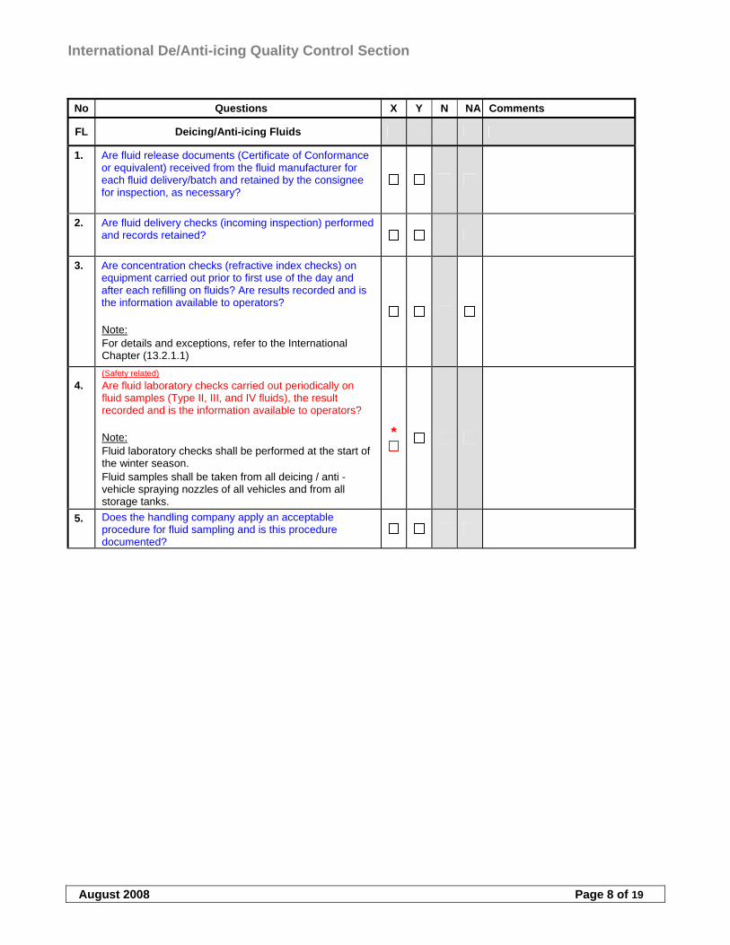
International De/Anti-icing Quality Control Section
August 2008 Page 8 of 19
No Questions X Y N NA Comments
FL Deicing/Anti-icing Fluids
1. Are fluid release documents (Certificate of Conformance or equivalent) received from the fluid manufacturer for each fluid delivery/batch and retained by the consignee for inspection, as necessary?
2. Are fluid delivery checks (incoming inspection) performed and records retained?
3. Are concentration checks (refractive index checks) on equipment carried out prior to first use of the day and after each refilling on fluids? Are results recorded and is the information available to operators? Note: For details and exceptions, refer to the International Chapter (13.2.1.1)
4. (Safety related) Are fluid laboratory checks carried out periodically on fluid samples (Type II, III, and IV fluids), the result recorded and is the information available to operators? Note: Fluid laboratory checks shall be performed at the start of the winter season. Fluid samples shall be taken from all deicing / anti -vehicle spraying nozzles of all vehicles and from all storage tanks.
*
5. Does the handling company apply an acceptable procedure for fluid sampling and is this procedure documented?
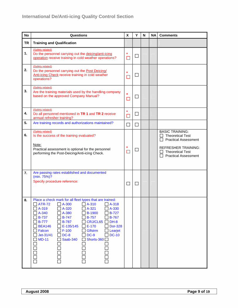
International De/Anti-icing Quality Control Section
August 2008 Page 9 of 19
No Questions X Y N NA Comments
TR Training and Qualification
1. (Safety related) Do the personnel carrying out the deicing/anti-icing operation receive training in cold weather operations?
*
2. (Safety related) Do the personnel carrying out the Post Deicing/ Anti-icing Check receive training in cold weather operations?
*
3. (Safety related) Are the training materials used by the handling company based on the approved Company Manual?
*
4. (Safety related) Do all personnel mentioned in TR 1 and TR 2 receive annual refresher training?
*
5. Are training records and authorizations maintained?
6. (Safety related) Is the success of the training evaluated? Note: Practical assessment is optional for the personnel performing the Post-Deicing/Anti-icing Check.
*
BASIC TRAINING: Theoretical Test Practical Assessment
REFRESHER TRAINING:
Theoretical Test Practical Assessment
7. Are passing rates established and documented (min. 75%)? Specify procedure reference:
8. Place a check mark for all fleet types that are trained: ATR-72 A-300 A-310 A-318 A-319 A-320 A-321 A-330 A-340 A-380 B-1900 B-727 B-737 B-747 B-757 B-767 B-777 B-787 CRJ/CL65 DH-8 BEA146 E-135/145 E-170 Dor-328 Falcon F-100 Glfstrm Learjet Jet-31/41 DC-8 DC-9 DC-10 MD-11 Saab-340 Shorts-360
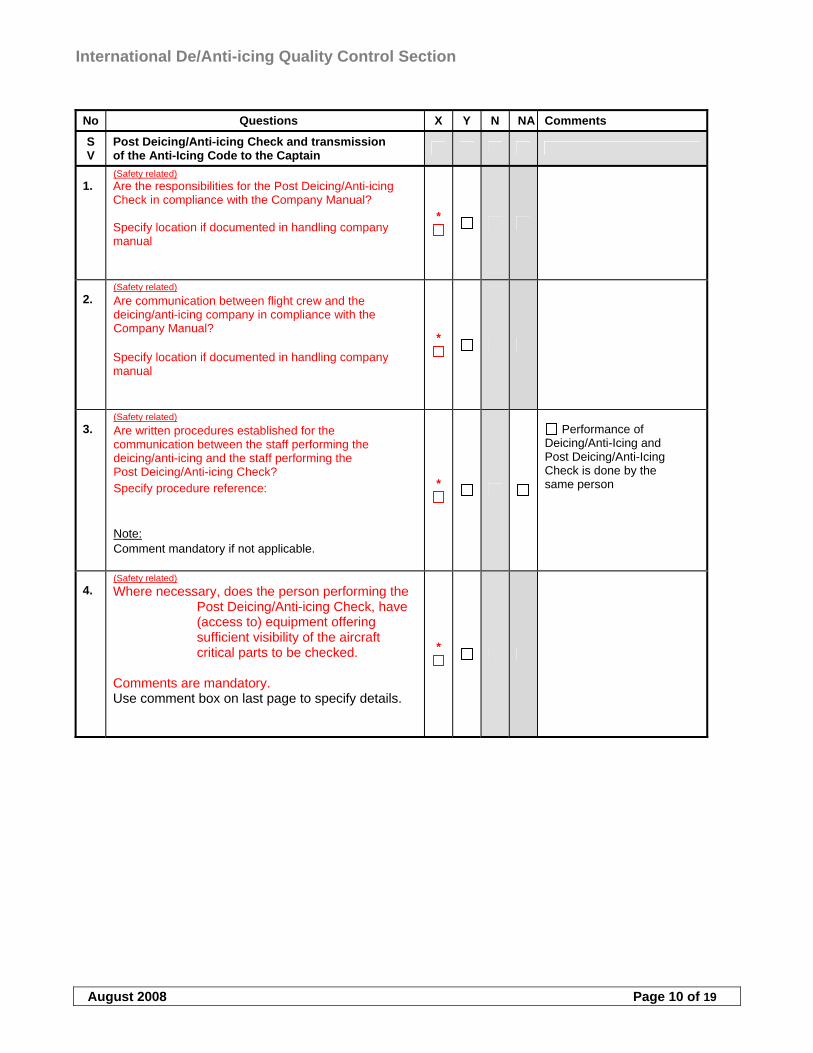
International De/Anti-icing Quality Control Section
August 2008 Page 10 of 19
No Questions X Y N NA Comments
SV
Post Deicing/Anti-icing Check and transmission of the Anti-Icing Code to the Captain
1. (Safety related) Are the responsibilities for the Post Deicing/Anti-icing Check in compliance with the Company Manual? Specify location if documented in handling company manual
*
2. (Safety related) Are communication between flight crew and the deicing/anti-icing company in compliance with the Company Manual? Specify location if documented in handling company manual
*
3. (Safety related) Are written procedures established for the communication between the staff performing the deicing/anti-icing and the staff performing the Post Deicing/Anti-icing Check? Specify procedure reference: Note: Comment mandatory if not applicable.
*
Performance of Deicing/Anti-Icing and Post Deicing/Anti-Icing Check is done by the same person
4. (Safety related) Where necessary, does the person performing the
Post Deicing/Anti-icing Check, have (access to) equipment offering sufficient visibility of the aircraft critical parts to be checked.
Comments are mandatory. Use comment box on last page to specify details.
*
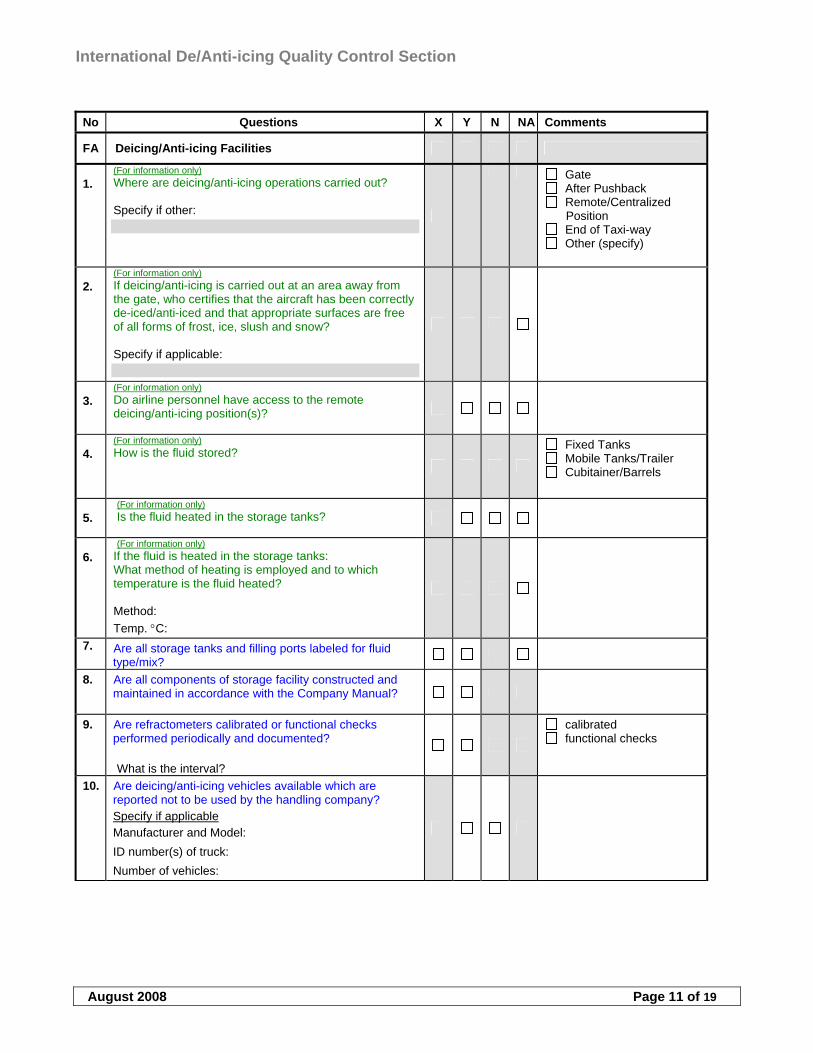
International De/Anti-icing Quality Control Section
August 2008 Page 11 of 19
No Questions X Y N NA Comments
FA Deicing/Anti-icing Facilities
1. (For information only) Where are deicing/anti-icing operations carried out? Specify if other:
Gate After Pushback Remote/Centralized
Position End of Taxi-way Other (specify)
2. (For information only) If deicing/anti-icing is carried out at an area away from the gate, who certifies that the aircraft has been correctly de-iced/anti-iced and that appropriate surfaces are free of all forms of frost, ice, slush and snow? Specify if applicable:
3. (For information only) Do airline personnel have access to the remote deicing/anti-icing position(s)?
4. (For information only) How is the fluid stored?
Fixed Tanks Mobile Tanks/Trailer Cubitainer/Barrels
5. (For information only) Is the fluid heated in the storage tanks?
6. (For information only)
If the fluid is heated in the storage tanks: What method of heating is employed and to which temperature is the fluid heated? Method:
Temp. C:
7. Are all storage tanks and filling ports labeled for fluid type/mix?
8. Are all components of storage facility constructed and maintained in accordance with the Company Manual?
9. Are refractometers calibrated or functional checks performed periodically and documented? What is the interval?
calibrated functional checks
10. Are deicing/anti-icing vehicles available which are reported not to be used by the handling company? Specify if applicable Manufacturer and Model:
ID number(s) of truck:
Number of vehicles:
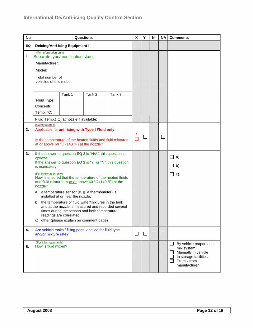
International De/Anti-icing Quality Control Section
August 2008 Page 12 of 19
No Questions X Y N NA Comments
EQ Deicing/Anti-icing Equipment I
(For information only) eSeparate type/modification state:
Manufacturer:
Model:
Total number of vehicles of this model:
Tank 1 Tank 2 Tank 3
Fluid Type:
Concentr:
Temp. C:
1.
Fluid Temp.(C) at nozzle if available:
2. (Safety related) Applicable for anti-icing with Type I Fluid only: Is the temperature of the heated fluids and fluid mixtures at or above 60 °C (140 °F) at the nozzle?
*
3. If the answer to question EQ 2 is “N/A”, this question is optional. If the answer to question EQ 2 is “Y” or “N”, this question is mandatory. (For information only)
How is ensured that the temperature of the heated fluids and fluid mixtures is at or above 60 °C (140 °F) at the nozzle?
a) a temperature sensor (e. g. a thermometer) is installed at or near the nozzle;
b) the temperature of fluid water/mixtures in the tank and at the nozzle is measured and recorded several times during the season and both temperature readings are correlated
c) other (please explain on comment page)
a)
b)
c)
4. Are vehicle tanks / filling ports labelled for fluid type and/or mixture rate?
5. (For information only)
How is fluid mixed?
By vehicle proportional mix system
Manually in vehicle In storage facilities Premix from
manufacturer
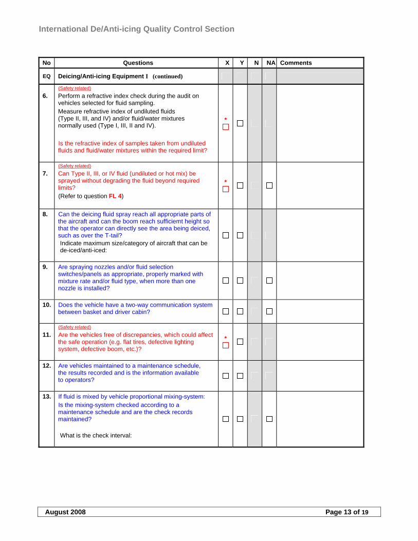
International De/Anti-icing Quality Control Section
August 2008 Page 13 of 19
No Questions X Y N NA Comments
EQ Deicing/Anti-icing Equipment I (continued)
6. (Safety related) Perform a refractive index check during the audit on vehicles selected for fluid sampling. Measure refractive index of undiluted fluids (Type II, III, and IV) and/or fluid/water mixtures normally used (Type I, III, II and IV).
Is the refractive index of samples taken from undiluted fluids and fluid/water mixtures within the required limit?
*
7. (Safety related) Can Type II, III, or IV fluid (undiluted or hot mix) be sprayed without degrading the fluid beyond required limits? (Refer to question FL 4)
*
8. Can the deicing fluid spray reach all appropriate parts of the aircraft and can the boom reach sufficiemt height so that the operator can directly see the area being deiced, such as over the T-tail? Indicate maximum size/category of aircraft that can be de-iced/anti-iced:
9. Are spraying nozzles and/or fluid selection switches/panels as appropriate, properly marked with mixture rate and/or fluid type, when more than one nozzle is installed?
10. Does the vehicle have a two-way communication system between basket and driver cabin?
11. (Safety related) Are the vehicles free of discrepancies, which could affect the safe operation (e.g. flat tires, defective lighting system, defective boom, etc.)?
*
12. Are vehicles maintained to a maintenance schedule, the results recorded and is the information available to operators?
13. If fluid is mixed by vehicle proportional mixing-system: Is the mixing-system checked according to a maintenance schedule and are the check records maintained? What is the check interval:

International De/Anti-icing Quality Control Section
August 2008 Page 14 of 19
No Questions X Y N NA Comments
EQ Deicing/Anti-icing Equipment II
(For information only) eSeparate type/modification state:
Manufacturer:
Model:
Total number of vehicles of this model:
Tank 1 Tank 2 Tank 3
Fluid Type:
Concentr:
Temp. C:
1.
Fluid Temp.(C) at nozzle if available:
2. (Safety related) Applicable for anti-icing with Type I Fluid only: Is the temperature of the heated fluids and fluid mixtures at or above 60 °C (140 °F) at the nozzle?
*
3. If the answer to question EQ 2 is “N/A”, this question is optional. If the answer to question EQ 2 is “Y” or “N”, this question is mandatory. (For information only)
How is ensured that the temperature of the heated fluids and fluid mixtures is at or above 60 °C (140 °F) at the nozzle?
a) a temperature sensor (e. g. a thermometer) is installed at or near the nozzle;
b) the temperature of fluid water/mixtures in the tank and at the nozzle is measured and recorded several times during the season and both temperature readings are correlated
c) other (please explain on comment page)
a)
b)
c)
4. Are vehicle tanks / filling ports labelled for fluid type and/or mixture rate?
5. (For information only)
How is fluid mixed?
By vehicle proportional mix system
Manually in vehicle In storage facilities Premix from
manufacturer
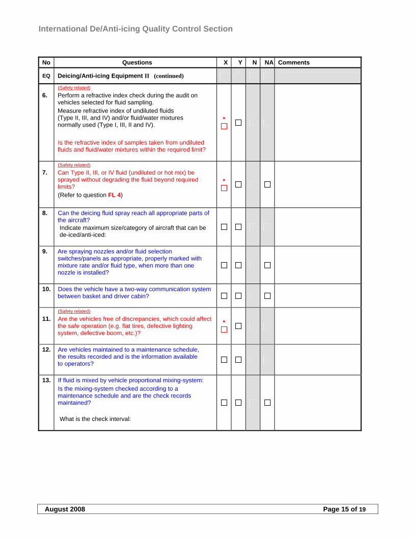
International De/Anti-icing Quality Control Section
August 2008 Page 15 of 19
No Questions X Y N NA Comments
EQ Deicing/Anti-icing Equipment II (continued)
6. (Safety related) Perform a refractive index check during the audit on vehicles selected for fluid sampling. Measure refractive index of undiluted fluids (Type II, III, and IV) and/or fluid/water mixtures normally used (Type I, III, II and IV).
Is the refractive index of samples taken from undiluted fluids and fluid/water mixtures within the required limit?
*
7. (Safety related) Can Type II, III, or IV fluid (undiluted or hot mix) be sprayed without degrading the fluid beyond required limits? (Refer to question FL 4)
*
8. Can the deicing fluid spray reach all appropriate parts of the aircraft? Indicate maximum size/category of aircraft that can be de-iced/anti-iced:
9. Are spraying nozzles and/or fluid selection switches/panels as appropriate, properly marked with mixture rate and/or fluid type, when more than one nozzle is installed?
10. Does the vehicle have a two-way communication system between basket and driver cabin?
11. (Safety related) Are the vehicles free of discrepancies, which could affect the safe operation (e.g. flat tires, defective lighting system, defective boom, etc.)?
*
12. Are vehicles maintained to a maintenance schedule, the results recorded and is the information available to operators?
13. If fluid is mixed by vehicle proportional mixing-system: Is the mixing-system checked according to a maintenance schedule and are the check records maintained? What is the check interval:
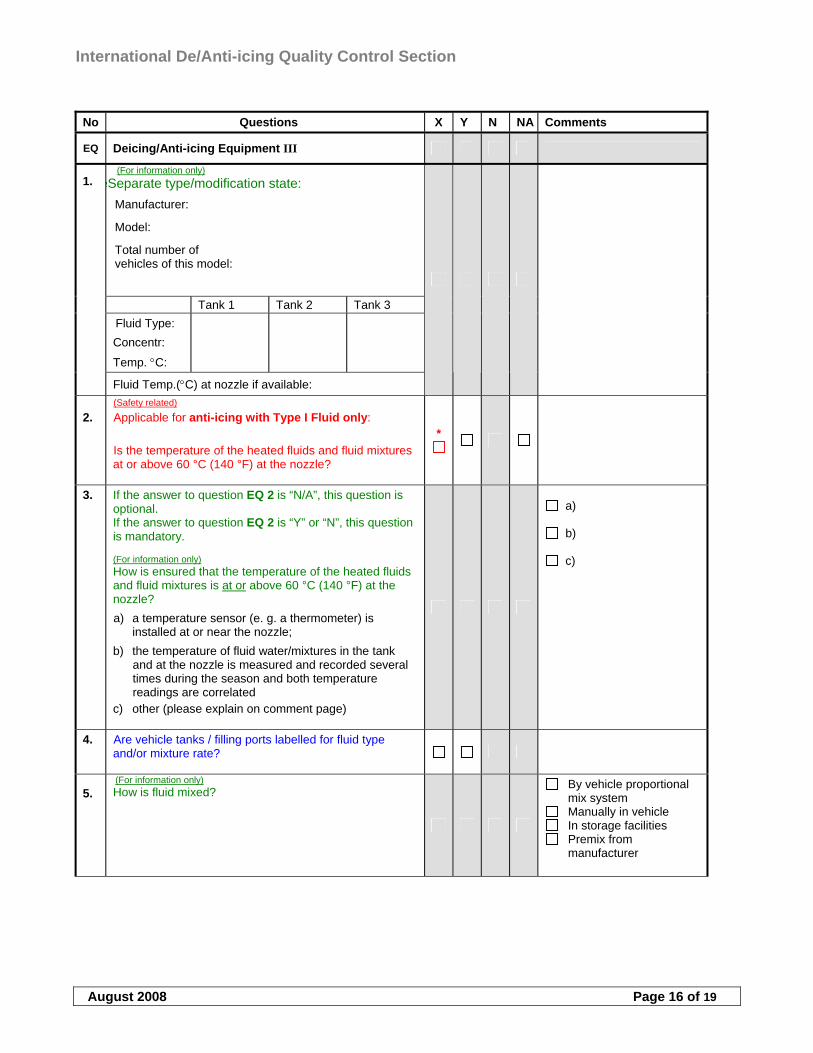
International De/Anti-icing Quality Control Section
August 2008 Page 16 of 19
No Questions X Y N NA Comments
EQ Deicing/Anti-icing Equipment III
(For information only) eSeparate type/modification state:
Manufacturer:
Model:
Total number of vehicles of this model:
Tank 1 Tank 2 Tank 3
Fluid Type:
Concentr:
Temp. C:
1.
Fluid Temp.(C) at nozzle if available:
2. (Safety related) Applicable for anti-icing with Type I Fluid only: Is the temperature of the heated fluids and fluid mixtures at or above 60 °C (140 °F) at the nozzle?
*
3. If the answer to question EQ 2 is “N/A”, this question is optional. If the answer to question EQ 2 is “Y” or “N”, this question is mandatory. (For information only)
How is ensured that the temperature of the heated fluids and fluid mixtures is at or above 60 °C (140 °F) at the nozzle?
a) a temperature sensor (e. g. a thermometer) is installed at or near the nozzle;
b) the temperature of fluid water/mixtures in the tank and at the nozzle is measured and recorded several times during the season and both temperature readings are correlated
c) other (please explain on comment page)
a)
b)
c)
4. Are vehicle tanks / filling ports labelled for fluid type and/or mixture rate?
5. (For information only)
How is fluid mixed?
By vehicle proportional mix system
Manually in vehicle In storage facilities Premix from
manufacturer
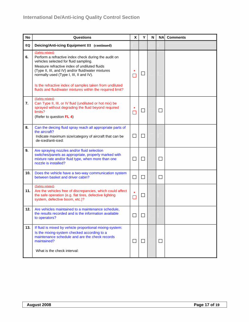
International De/Anti-icing Quality Control Section
August 2008 Page 17 of 19
No Questions X Y N NA Comments
EQ Deicing/Anti-icing Equipment III (continued)
6. (Safety related) Perform a refractive index check during the audit on vehicles selected for fluid sampling. Measure refractive index of undiluted fluids (Type II, III, and IV) and/or fluid/water mixtures normally used (Type I, III, II and IV).
Is the refractive index of samples taken from undiluted fluids and fluid/water mixtures within the required limit?
*
7. (Safety related) Can Type II, III, or IV fluid (undiluted or hot mix) be sprayed without degrading the fluid beyond required limits? (Refer to question FL 4)
*
8. Can the deicing fluid spray reach all appropriate parts of the aircraft? Indicate maximum size/category of aircraft that can be de-iced/anti-iced:
9. Are spraying nozzles and/or fluid selection switches/panels as appropriate, properly marked with mixture rate and/or fluid type, when more than one nozzle is installed?
10. Does the vehicle have a two-way communication system between basket and driver cabin?
11. (Safety related) Are the vehicles free of discrepancies, which could affect the safe operation (e.g. flat tires, defective lighting system, defective boom, etc.)?
*
12. Are vehicles maintained to a maintenance schedule, the results recorded and is the information available to operators?
13. If fluid is mixed by vehicle proportional mixing-system: Is the mixing-system checked according to a maintenance schedule and are the check records maintained? What is the check interval:
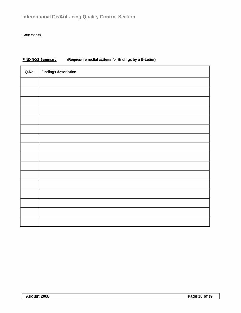
International De/Anti-icing Quality Control Section
August 2008 Page 18 of 19
Comments FINDINGS Summary (Request remedial actions for findings by a B-Letter)
Q-No. Findings description
International De/Anti-icing Quality Control Section
August 2008 Page 19 of 19
2 DEVA Checklists
International De/Anti-icing Reference Section
August 2008 Page 1 of 20
TABLE OF CONTENTS
1 AERODYNAMICS................................................................................................................................................... 2
1.1 GENERAL....................................................................................................................................................................2 1.1.1 Forces involved..................................................................................................................................................2 1.1.2 Aerodynamic areas ............................................................................................................................................2 1.1.3 Aircraft surfaces ................................................................................................................................................2 1.1.4 How contamination affects lift and performance...............................................................................................3 1.1.5 Fluid behaviour on aircraft surfaces .................................................................................................................4
2 WEATHER ............................................................................................................................................................... 5
2.1 RELEVANT WEATHER ASPECTS ...................................................................................................................................5 2.1.1 Weather terminology..........................................................................................................................................5 2.1.2 Explanation of weather terms ............................................................................................................................5 2.1.3 Interpreting weather data ..................................................................................................................................7 2.1.4 Ice formation......................................................................................................................................................8 2.1.5 Frost formation................................................................................................................................................10 2.1.6 Weather effects on aircraft operations.............................................................................................................10 2.1.7 Weather categories ..........................................................................................................................................10 2.1.8 Weather effects on fluid behaviour ..................................................................................................................11
3 HEALTH AND SAFETY....................................................................................................................................... 12
3.1 GENERAL..................................................................................................................................................................12 3.1.1 Deicing fluids...................................................................................................................................................12 3.1.2 Personal health and safety...............................................................................................................................13 3.1.3 Operational safety ...........................................................................................................................................13 3.1.4 Human factors .................................................................................................................................................14
4 DEICING/ANTI-ICING FLUIDS......................................................................................................................... 15
4.1 DEICING FLUIDS........................................................................................................................................................15 4.1.1 WSET/HHET/Holdover time............................................................................................................................15 4.1.2 Aerodynamic acceptance .................................................................................................................................16 4.1.3 Material compatibility and other tests .............................................................................................................16 4.1.4 Non-thickened fluids ........................................................................................................................................16 4.1.5 Thickened fluids ...............................................................................................................................................17
International De/Anti-icing Reference Section
August 2008 Page 2 of 20
1 AERODYNAMICS
1.1 General
This section explains how operating in winter conditions can affect aircraft performance. The basic concept will be introduced of how any contamination affects the performance and why the deicing ground crew should note any and all factors relating to the aerodynamic surfaces of the aircraft. Subjects in this section are simplified to a large extent and further investigation would clarify issues in more detail but this is not necessary for the deicing ground crew. The specific performance of any aircraft is calculated and tested with the assumption that all of its aerodynamic surfaces are clean. Any contamination will affect this performance and such a decrease in performance and control has not necessarily been assessed. The clean aircraft concept must be very clear for a deicing ground crew. As a rule of thumb “make it clean and keep it clean”.
1.1.1 Forces involved
An aircraft is subjected to four forces, Lift, Drag, Thrust and Weight. For an aircraft to fly straight and level, all these forces must be balanced. A change in any one of these forces will affect this balance. This change can be either intended or unintended (e.g. icing). Frost, snow, slush or ice accretion has a negative effect on all these forces. Lift lessens, drag increases, weight increases and available excess thrust decreases. Contamination also affects the stall angle of attack by decreasing it, which could be very harmful at takeoff. It is up to the deicing crew to clean the aircraft and protect it so it is aerodynamically “clean” until takeoff after which the flight crew can operate the aircraft’s own deicing/anti-icing systems to protect the critical parts of the aircraft.
1.1.1.1 Basic aerodynamics
The critical effects of contamination are the resulting decrease in lift and manoeuvrability. The leading edges of the wing and of the vertical and horizontal stabilizers are the most critical areas with regard to the airflow around the aircraft. This part is where the airflow is divided evenly around the wing surface (or tail surfaces). As the angle of a wing to the airflow (the angle of attack) is increased, the air flows evenly along the surfaces at first (called laminar), but then after a certain point starts to break away (called turbulent) depending on the angle of attack. Any contamination at the leading edge will upset this flow and it will break off earlier than intended causing a loss of lift. The aircraft moves around three axes, Longitudinal, Horizontal and Vertical. The flight crew controls this movement by changing the position of the ailerons, rudder and/or the elevator depending on the particular flight situation. Any contamination on these control surfaces may restrict their movement or cause them to be ineffective (because of incorrect airflow) and in worst case cause a loss of control.
1.1.2 Aerodynamic areas
Basically the entire aircraft is designed to divide the airflow in a particular way and any contamination will disturb this flow. The wings and the tail are the main concern but also secondary parts such as slats, flaps, ailerons, rudder, elevator and tabs are critical for the correct airflow, especially the leading edges where the airflow is divided. It is important that the deicing crew can identify these parts because the success of removal of contamination and protection from icing has a direct impact on lifting and manoeuvrability. Many aircraft are designed in different ways but the basic lifting physics remain the same. Any part on the aircraft that changes the airflow is there for a reason and the deicing ground crew must assure that these areas are free of contamination whether they are considered a critical lifting surface or not. Such other aerodynamic parts on an aircraft can be strakes, vortilons, winglets, pylons, stall strips/vanes, vortex generators etc.
1.1.3 Aircraft surfaces
The importance of cleaning the leading edges of the wings and tail was mentioned earlier. However, lowering slats and flaps exposes new surfaces and leading edges where contamination can adhere. If slats and flaps are in a lowered position while the aircraft is on the ground such areas shall be checked and cleaned/protected if
International De/Anti-icing Reference Section
August 2008 Page 3 of 20
necessary. Contamination on these parts will cause irregular airflow and manoeuvrability problems when they are lowered in flight. The fuselage is not a critical lifting surface but contamination shall be removed in the same manner as other surfaces. The main concern is that snow, slush or ice will break off and damage the engine or aircraft surfaces that can cause a dangerous situation during takeoff. Frost may be allowed to a certain extent depending on aircraft manufacturer’s requirements and company procedures. The upper surfaces of the wings and tail are not the only area to check and treat. The lower surfaces are also highly important. The wing lower surfaces shall be free of ice but frost may be allowed in some areas (fueltank area) depending on aircraft manufacturer’s requirements and company procedures. However, the horizontal stabilizer lower surface shall be clean in all cases. The horizontal stabilizer creates a lifting force either up or down depending on how the elevator (and tabs) is positioned. This tail down force is pronounced during takeoff and shall therefore be verified clean on both sides.
1.1.4 How contamination affects lift and performance
It is obvious that if the aircraft is covered with large amounts of snow, sleet/slush or ice, that it will affect lift and performance, but even “lighter” contamination such as frost can still have a considerable negative effect. Even if the loss of performance is not enough on it’s own to cause an accident, safety margins can be reduced, so that if another problem arises, such as an engine failure, the combination of problems may be enough to transform an incident into a major accident. Any loss of performance will also cause the aircraft to use more fuel, but this chapter’s main focus is on the flight safety consequences of contaminated aircraft surfaces, rather than the financial impact.
1.1.4.1 Frost affecting lift
Tests have been performed on how a different thickness of frost effects the lifting performance. The effect on other types of aircraft may be similar, this particular example happens to compare the performance of a narrow body jet aircraft. Three scenarios where compared, clean wing, a thin layer of frost (e.g. 1 mm or less) and a thick layer of frost (e.g. 1-2,5 mm). First normal takeoffs with these layers where compared then takeoffs with an engine-out situation with the same layers. Commercial airliners are fitted with powerful engines that in normal cases produce a certain amount of excess thrust. This is seen as only a marginal liftloss in normal takeoff situations. A thick layer of frost has some effect on normal lifting performance but it is not dramatic. However, when there is an engine-out situation with these contamination layers, it can be seen that even a thin layer of frost may have a notable effect on lift compared to a clean wing under these conditions. When there is a thick layer of frost during an engine-out on takeoff, lifting capabilities may be dramatically reduced. It must be noted that these situations may differ greatly between different aircraft and in some cases frost may even be allowed to some extent. Aircraft manufacturer limitations shall be noted in all cases.
1.1.4.2 Frost affecting stall
Tests have also been performed of how different thickness of frost affect the stall performance/speed with a certain angle of attack. This particular example compares a narrow body jet aircraft. Each aircraft has a particular angle of attack when lift is reduced and it is said to stall. The higher the angle of attack the more lift is produced, this is a phenomenon needed particularly during takeoff (and landing). When a thin layer of frost is on the wing, it reduces the maximum angle of attack (CL-max) by a certain amount and the wing stalls earlier than anticipated/calculated even without any stall warning. This scenario can be put into a certain velocity and in this case it stalls somewhat earlier than anticipated (with the same takeoff angle). The same scenario can be seen with a thicker layer of frost but in this case the effect is more dramatic. Putting into a velocity, it stalls notably earlier than anticipated.
1.1.4.3 Other effects on performance
It is clear that contamination will affect the amount of drag on an aircraft. The more contamination located on an aircraft the more drag and thus less performance. This contamination does not have to be on aerodynamic surfaces (which must be cleaned anyway) to create drag, it can be on the landing gear, fuselage etc. These areas must be cleaned but as an example it can produce drag even if it does not directly affect lift. Thrust must always be added (if excess thrust is available) to compensate for the reduced performance. This is perhaps
International De/Anti-icing Reference Section
August 2008 Page 4 of 20
even more notable on propeller aircraft. The propeller is in itself a lifting device and its surface must be clean (the proper cleaning procedures according to A/C manufacturer’s requirements). Any contamination of the blade surface can reduce the pulling force effectiveness of the propeller. Vibration of the propeller(s) due to contamination may also be a factor to note. The same applies for jet driven aircraft. A visual check of the fan blades and especially on the rear side of the fanblades is necessary to detect frozen contamination adhering to them. This can lead to vibration, performance loss and even engine damage.
1.1.5 Fluid behaviour on aircraft surfaces
Deicing/anti-icing fluids can be misunderstood to be an equal contaminant on the wing as for example slush/sleet. Fluids have been tested and manufactured to perform in a certain way. This has been aerodynamically tested and it is evident that the fluid is sheared from the wing at takeoff leaving only a marginal film of fluid that does not constitute a notable aerodynamic effect. Different fluids are thicker than others are (Type-I vs. Type-II/III/IV) and less viscous fluid drain off easier than thicker fluid. Failed fluid no longer performs aerodynamically as expected. At this point the fluid is comparable to any other contamination. Also old fluid (e.g. after a flight) sticking to the surface should be removed because it neither performs correctly. Tests have been made on how the fluid effects lifting performance at certain rotational speed, rate and angle of attack etc. This data is still under study. Certain aircraft types and airlines need to know the fluid (and coverage) on the surface in order to correct thrust settings, V-speeds etc. Restrictions also apply for certain aircraft types and airline procedures on the flight performance. Additional rotation speed, airspeed in general, runway length and added weight are examples of how deicing/anti-icing fluids can set restrictions or add procedures for the flight.
International De/Anti-icing Reference Section
August 2008 Page 5 of 20
2 WEATHER
2.1 Relevant weather aspects
Weather is complex and at times difficult to understand. Our restless atmosphere is almost constantly in motion as it strives to reach equilibrium. These never-ending air movements set up chain reactions, which culminate in a continuing variety of weather. The climate of any particular region is largely determined by the amount of energy received from the sun, but the local geography of the area also influences the climate. We are prepared to face “problems” in areas where winter is unavoidable but there can be a hidden danger at regions where winter weather aspects are not so obvious. The main point is to be aware of how, where and why ice, in its different forms (and relating forms of frost and snow), can build up.
2.1.1 Weather terminology
Weather terminology can be seen and heard from various weather information sources. The general terms are standardised and they are adapted in the same way everywhere. Weather information is essential for the deicing crew in the sense that official temperature and weather characters must be obtained for proper analysis of deicing, anti-icing, mixture and holdover time procedures. Weather abbreviations can be found in Annex B. The intensity can be marked as light (-) or heavy (+), otherwise it is considered moderate intensity (no marking). Note: intensity in MET reports is defined according to horizontal visibility. The actual accumulation of precipitation and horizontal visibility may in some cases not be comparable and therefore caution must be taken when intrepeting the intensity.
2.1.2 Explanation of weather terms
Active frost: Active frost is a condition when frost is forming. Active frost occurs when aircraft surface temperature is at or below 0 ºC (32F) and at or below dew point. Change of state: The transformation of water from one form (e.g. solid (ice), liquid, or gaseous (water vapour), to any other form). (a) Condensation: the change of water vapour to liquid (b) Evaporation: the change of liquid water to water vapour (c) Freezing: the change of liquid water to ice (d) Melting: the change of ice to liquid water (e) Sublimation: the change of (1) ice to water vapour or (2) water vapour to ice (also called deposition) Clear ice: The formation of a layer or mass of ice which is relatively transparent because of its homogeneous structure and small number and size of air spaces. Factors, which favour clear icing, are large drop size, rapid accretion of supercooled water and slow dissipation of latent heat of fusion. Aircraft are most vulnerable to this type of build-up, when: (a) Wing temperatures remain well below 0C during the turnaround/transit (b) Ambient temperatures between -2C and +15C are experienced (note: Clear ice can form at other
temperatures if conditions (a), (c) and (d) exist) (c) Precipitation occurs while aircraft is on the ground and/or (d) Frost or ice is present on lower surface of either wing. Cold-soak effect: The wings of aircraft are said to be “cold-soaked” when they contain very cold fuel as a result of having just landed after a flight at high altitude or from having been re-fuelled with very cold fuel. Whenever precipitation falls on a cold-soaked aircraft when on the ground, clear icing may occur. Even in ambient temperatures between -2C and +15C, ice or frost can form in the presence of visible moisture or high humidity if the aircraft structure remains at 0C or below. Clear ice is very difficult to be detected visually and may break loose during
International De/Anti-icing Reference Section
August 2008 Page 6 of 20
or after takeoff. The following factors contribute to cold-soaking: temperature and quantity of fuel in fuel cells, type and location of fuel cells, length of time at high altitude flights, temperature of re-fuelled fuel and time since re-fuelling. Cold front: Any non-occluded front, which moves in such a way that colder air, replaces warmer air. Dew point: The temperature to which a sample of air must be cooled, while the amount of moisture and barometric pressure remain constant, in order to attain saturation with respect to water. Drizzle: A form of precipitation. Very small water droplets (diameter less than 0,5mm) that appear to float with the air currents while falling in an irregular path (unlike rain, which fall in a comparatively straight path and unlike fog droplets which remain suspended in the air). Freezing drizzle: Fairly uniform precipitation composed exclusively of fine droplets (diameter less than 0.5 mm (0.02 in)) very close together which freezes upon impact with the ground or other exposed objects. Freezing fog: A suspension of numerous minute water droplets which freeze upon impact with ground or other exposed objects, generally reducing the horizontal visibility at the earth's surface to less than 1 km (5/8 mile). Frost/hoar frost: Ice crystals that form from ice saturated air at temperatures below 0°C (32°F) by direct sublimation on the ground or other exposed objects. Hail: Precipitation of small balls or pieces of ice with a diameter ranging from 5 to 50 mm (0.2 to >2.0 in.) falling either separately or agglomerated. Ice pellets: Precipitation of transparent (grains of ice), or translucent (small hail) pellets of ice, which are spherical or irregular, and which have a diameter of 5 mm (0.2 in.) or less. The pellets of ice usually bounce when hitting hard ground. Light* freezing rain: Precipitation of liquid water particles which freezes upon impact with the ground or other exposed objects, either in the form of drops of more than 0.5 mm (0.02 inch) or smaller drops which, in contrast to drizzle, are widely separated. Measured intensity of liquid water particles is up to 2.5 mm/hour (0.10 inch/hour) or 25 grams/dm2/hour with a maximum of 0.25-mm (0.01 inch) in 6 minutes. Lowest operational use temperature (LOUT):
The lowest operational use temperature (LOUT) is the higher (warmer) of a)The lowest temperature at which the fluid meets the aerodynamic acceptance test (according to AS5900) for a given type (high speed or low speed) of aircraft or b)The freezing point of the fluid plus the freezing point buffer of 10°C for Type I fluid and 7°C for Type II, III or IV fluids. For applicable values refer to the fluid manufacturer’s documentation Moderate* and heavy* freezing rain: Precipitation of liquid water particles which freezes upon impact with the ground or other exposed objects, either in the form of drops of more than 0.5 mm (0.02 inch) or smaller drops which, in contrast to drizzle, are widely
International De/Anti-icing Reference Section
August 2008 Page 7 of 20
separated. Measured intensity of liquid water particles is more than 2.5 mm/hour (0.10 inch/hour) or 25 grams/dm2/hour. Rain or high humidity (on cold soaked wing): Water, visible moisture, or humidity forming ice or frost on the wing surface, when the temperature of the aircraft wing surface is at or below 0°C (32°F). Rain and snow: Precipitation in the form of a mixture of rain and snow.
Relative humidity:
The ratio of the existing amount of water vapour in the air at a given temperature to the maximum amount that could exist at that temperature (usually expressed in percent).
Saturation:
The condition of the atmosphere when actual water vapour present is the maximum possible at existing temperatures.
Snow: Precipitation of ice crystals, most of which are branched, star-shaped or mixed with unbranched crystals. At temperatures higher than -5°C (23°F), the crystals are generally agglomerated into snowflakes. Snow grains: Precipitation of very small white and opaque particles of ice that are fairly flat or elongated with a diameter of less than 1 mm (0.04 in.). When snow grains hit hard ground, they do not bounce or shatter. Snow pellets: Precipitation of white, opaque particles of ice. The particles are round or sometimes conical; their diameter range from about 2-5 mm (0.08-0.2 in.). Snow pellets are brittle, easily crushed; they do bounce and may break on hard ground. Slush: Snow or ice that has been reduced to a soft watery mixture by rain, warm temperatures and/or chemical treatment. Supercooled water: Liquid water at temperatures colder than freezing. Warm front: Any non-occluded front, which moves in such a way that warmer air, replaces colder air. Water vapour: Water in the invisible gaseous form. * Note: intensity in MET reports is defined according to horizontal visibility.
2.1.3 Interpreting weather data
Weather information can be gathered from various sources. Some of this written information can be difficult to understand at times but they all follow the same logic. As for the deicing crew, temperature, dewpoint, precipitation, intensity and forecast information are elements that affect the operation. Some of these terms are explained below as well as an example of a local meteorological report. METAR Meteorological Report (local), also METREP, SPECI, AUTO-METAR. Reported
normally every 30 min. Includes a possible TREND-forecast. Informs of the current weather situation. An example report:
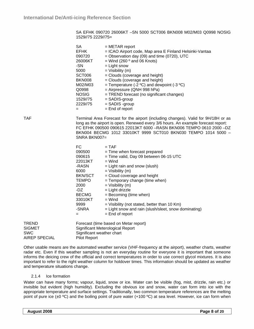
International De/Anti-icing Reference Section
August 2008 Page 8 of 20
SA EFHK 090720 26006KT –SN 5000 SCT006 BKN008 M02/M03 Q0998 NOSIG 1529//75 2229//75= SA = METAR report EFHK = ICAO Airport code, Map area E Finland Helsinki-Vantaa 090720 = Observation day (09) and time (0720), UTC 26006KT = Wind (260 º and 06 Knots) -SN = Light snow 5000 = Visibility (m) SCT006 = Clouds (coverage and height) BKN008 = Clouds (coverage and height) M02/M03 = Temperature (-2 ºC) and dewpoint (-3 ºC) Q0998 = Airpressure (QNH 998 hPa) NOSIG = TREND forecast (no significant changes) 1529//75 = SADIS-group 2229//75 = SADIS -group = = End of report
TAF Terminal Area Forecast for the airport (including changes). Valid for 9H/18H or as
long as the airport is open. Renewed every 3/6 hours. An example forecast report: FC EFHK 090500 090615 22013KT 6000 –RASN BKN006 TEMPO 0610 2000 –DZ
BKN004 BECMG 1012 33010KT 9999 SCT010 BKN030 TEMPO 1014 5000 –SNRA BKN007=
FC = TAF 090500 = Time when forecast prepared 090615 = Time valid, Day 09 between 06-15 UTC 22013KT = Wind -RASN = Light rain and snow (slush) 6000 = Visibility (m) BKN/SCT = Cloud coverage and height TEMPO = Temporary change (time when) 2000 = Visibility (m) -DZ = Light drizzle BECMG = Becoming (time when) 33010KT = Wind 9999 = Visibility (not stated, better than 10 Km) -SNRA = Light snow and rain (slush/sleet, snow dominating) = = End of report TREND Forecast (time based on Metar report) SIGMET Significant Meterological Report SWC Significant weather chart AIREP SPECIAL Pilot Report Other usable means are the automated weather service (VHF-frequency at the airport), weather charts, weather radar etc. Even if this weather sampling is not an everyday routine for everyone it is important that someone informs the deicing crew of the official and correct temperatures in order to use correct glycol mixtures. It is also important to refer to the right weather column for holdover times. This information should be updated as weather and temperature situations change.
2.1.4 Ice formation
Water can have many forms; vapour, liquid, snow or ice. Water can be visible (fog, mist, drizzle, rain etc.) or invisible but evident (high humidity). Excluding the obvious ice and snow, water can form into ice with the appropriate temperature and surface settings. Traditionally, two common temperature references are the melting point of pure ice (±0 ºC) and the boiling point of pure water (+100 ºC) at sea level. However, ice can form when
International De/Anti-icing Reference Section
August 2008 Page 9 of 20
the difference between the air temperature and dew point is small (indicating a high humidity) and when surface temperature (e.g. wing) is close to ±0 ºC even if the outside air temperature is well above freezing. This phenomenon can happen whenever the wingtank contains cold fuel and conditions are right. Icing is perhaps more of a problem for the flight crew in flight but whenever the right conditions exist on ground each trained and qualified deicing ground crew should be aware of the event.
2.1.4.1 Areas of ice build-up
There is no one single rule of where ice can be found. It may be local in extent and different in character. A big concern is whenever a temperature close to ±0 ºC exist and there has been some rain or snowfall after which the temperature drops below freezing and all the rain or melted snow freezes. In worst cases it can be hidden underneath a layer of snow. Clear ice is like it sounds, clear and difficult (if not impossible) to see. A normal area of ice build up on an aircraft is the tank area. The cold fuel causes the aircraft surface (tank area) to drop close to or below ±0 ºC, which in turn reacts with the moist air and freezes. A hand feel check is the best way to verify the presence (or removal) of ice. Tank areas are not only located at the wing root, they can also be located at the wingtip and in the tail section. Water blown by propellers or jet engines, splashed by wheels of an aircraft as it taxis or runs through pools of water or slush may result in serious aircraft icing. Ice may form in wheel wells, brake mechanisms, flap hinges, antennas etc. and prevent the proper operation of these parts. Water may freeze in cavities and it is very hard to note without a closer inspection. Fan blades of a jet engine can be susceptible for icing if conditions are right. Ice fog and high humidity in general may be a major factor contributing to fan blade icing. Aircraft may experience icing while flying through clouds for landing. Icing can be found on all leading edge and frontal areas after landing. The heated aircraft cabin will melt any ice and/or snow from top of the fuselage and the melted water will drain downwards and freeze on the wings and underneath the fuselage. All these areas must be checked and proper treatment performed if necessary. Super cooled water increases the rate of icing and is essential to rapid accretion. A condition favorable for rapid accumulation of clear icing is freezing rain below a frontal surface. Rain forms above the frontal surface at temperatures warmer than freezing. Subsequently, it falls through air at temperatures below freezing and becomes super cooled. The super cooled drops freeze on impact with an aircraft surface. It may occur with either a warm front or a cold front. The rain does not necessarily need to be super cooled to freeze. As mentioned earlier, if the aircraft surface area is very cold then rain can freeze as well. Freezing fog is relatively same in character as supercooled rain; it tends to freeze on impact. Fog can also cause frost and it may well cover the whole aircraft. The difference of ice creation caused by FZFG and FZRA differs by droplet size and humidity also differs depending on the airmass, cold air is dryer than warm air. Icing may occur during any season of the year but in temperate climates, icing is more frequent in winter. Polar Regions have the most notable icing in spring and fall. During the winter the air is normally too cold in the Polar Regions to contain heavy concentrations of moisture necessary for icing. This does not, however, rule out the possibility of icing in these areas. Arctic areas, as could be expected, is very cold in winter but due to local terrain and the movement of pressure systems, occasionally some areas are surprisingly warm.
2.1.4.2 Hazards of ice on aircraft
Ice, snow and slush have a direct impact on the safety of flight. Not only because it degrades lift and takeoff performance/manoeuvrability but it can also cause engine failures and structural damage. Mainly fuselage aft-mounted engines are susceptible for this FOD (Foreign Object Damage) phenomenon caused by winter operations. But it does not exclude wing-mounted engines. Ice can be present on any part of the aircraft and when it breaks off there is some probability that it could go into the engine. The worst case is that ice on the wing breaks off during takeoff due to the flexing off the wing and goes directly into the engine (or both) leading to surge, vibration and complete thrust loss. Snow, even light snow, which is loose on the surfaces and the fuselage, can also cause engine damage leading to surge, vibration and thrust loss. Leakage of the water and waste panels can cause ice build-up, which will break off causing damage and hazardous situations. Even if the ice does not go into an engine it can severely damage the structure of e.g. the tail surfaces (mainly leading edges) causing unbalanced airflow or even vibration problems. It should also be
International De/Anti-icing Reference Section
August 2008 Page 10 of 20
noted that ice could fall down on the ground during takeoff and flight causing dangerous situations for anyone or anything. Ice damage is not only a safety related issue (even if it is the most important one) but it is also a financial burden for airlines. All damages have a price tag and an engine overhaul is not cheap. This economical burden will ultimately affect the passengers as a side effect. FOD-problems due to icing on ground are preventable and here is where the deicing crew have an important role.
2.1.5 Frost formation
Frost can form because of many reasons. Frost forms near the surface primarily in clear, stable air and with light winds. Thin metal airfoils are especially vulnerable surfaces on which frost will form. Frost does not change the basic aerodynamic shape of the wing, but the roughness of its surface spoils the smooth flow of air thus causing a slowing of the airflow. This slowing of the air causes early flow separation over the affected airfoil resulting in a lift loss (explained in 3.1.4.1). In coastal areas during spring, fall and winter, heavy frost and rime may form on aircraft parked outside, especially when fog or ice fog is present. Wing surface temperatures can be considerably below ambient temperature due to contact with cold fuel and/or close proximity to large masses of cold soaked metal. In these areas frost can build up on wing surfaces and may result in the entire wing being de-iced/anti-iced prior to the subsequent departure. A special procedure provides recommendations for the prevention of local frost formation in cold soaked wing tank areas during transit stops in order to make deicing/anti-icing of the entire wings unnecessary under such circumstances. This procedure does, however, not supersede standard deicing/anti-icing procedures and has to fulfil the proper requirements. This procedure also does not relieve from any requirements for treatment and inspections in accordance with aircraft manufacturer manuals. Hoarfrost may be allowed so that the markings on the fuselage still are readable. A layer of frost due to cold fuel may be allowed on the underwing surfaces. No frost is allowed outside the tank area on the underwing surfaces. The flight crew shall be informed of the possible frost so that they can make the possible recalculations concerning the take-off. The lower surfaces of the horizontal stabilizer shall be clear of frost and ice. Company and aircraft manufacturer limits for allowing a certain amount of frost (and areas where allowed) should be noted.
2.1.6 Weather effects on aircraft operations
Winter operation in harsh climates is bound to affect the punctuality of any airline. Not only is ground operations impaired but also snow and ice on apron, taxiway and runway areas affect aircraft operations as well. However, there is no short cut to a safe deicing/anti-icing procedure on ground. Flights are, irrespective of season, in some cases restricted with a certain take-off time (ctot). This “window” of departure causes undue pressure for the completion of ground procedures but this shall not cause any diversions in normal and safe deicing/anti-icing procedures. Heavy winter weather conditions make the deicing ground procedure to be more a normal task than an exception to consider. Airlines that do not operate on a regular basis to these areas might not be as aware of the importance for an appropriate inspection and treatment. Milder winter seasons in warmer regions do not rule out the importance of an equal deicing/anti-icing performance as in other regions.
2.1.7 Weather categories
Deicing/anti-icing procedures and their respective holdover timetables are set according to some weather elements. These tables do not necessarily cover all the phenomena that can be experienced during a winter season but they give a compromise of choices where different elements can be included. Some weather elements do not include tested holdover times and caution should be used if any particular weather is in this category. Each weather category has its relevant temperature indication range. These weather categories include: (a) Active frost (b) Freezing fog (c) Snow/Snow grains (d) Freezing drizzle
International De/Anti-icing Reference Section
August 2008 Page 11 of 20
(e) Light freezing rain (f) Rain on cold soaked wing (g) Other* * Other conditions are: Heavy snows, snow pellets, ice pellets, hail, moderate freezing rain and heavy freezing rain Each box in the table contains an estimated time window for that particular holdover time. This range of time depends on the intensity and the decision of choice rests with the flight crew according to their estimate. In some cases the Snow/snow grains-column is divided into two additional parts, light snow and very light snow. The decision of what category to use lies with the pilot in command, unless the airport is equipped with such instrumentation that can make a correct and accurate report on each weather element and its intensity covering the whole area. Other elements, such as wind, jetblast etc. will affect each respective weather category and its relevant holdover time. These conditions should be taken into account when looking into a particular table. Each holdover timetable should be reviewed recurrently and verified that the latest revision is used (these examples are only for reference).
2.1.8 Weather effects on fluid behaviour
Weather not only causes the need for deicing and anti-icing it will also affect the performance of the fluids. Each fluid has a particular holdover time. This holdover time is dependent on different weather factors. The fluid can withstand a certain amount of water (in forms of snow, slush, rain etc.) until it becomes so diluted (or saturated) that it no longer gives protection against freezing or fulfils aerodynamic criteria. Further, wind has its own affect on how even the fluid layer is on the surface and can also lower the actual outside air temperature. Very cold temperatures also limit the use of glycol (variable with different compounds) both for anti-icing and deicing. The viscosity of glycol also changes with temperature (variable for different fluids) and it in turn affects how the fluid is sprayed and how it drains off the surfaces.
International De/Anti-icing Reference Section
August 2008 Page 12 of 20
3 HEALTH AND SAFETY
3.1 General
Safety is an issue concerning everyone involved. Operational safety, equipment safety, flight safety, personal safety and health etc. are elements that need to be checked and verified for proper procedures. Many companies and airlines have their own manuals regarding the subject and they should be followed. The airport may dictate general rules of conduct in emergency situations (and special cases) from an airport operations point of view and by the operators from a company point of view. Airport equipment need to be qualified for every specific task accordingly and the personnel using them shall have the proper training and qualification for its use. The airport is planned for aircraft operations but there has to be a large amount of ground service equipment to fulfil all the tasks needed for an efficient and safe departure. All this “action” on the ground can lead to many “close encounters” and procedural training should be performed for the whole ground staff for each particular task and for the apron operation in general.
3.1.1 Deicing fluids
Many different deicing/anti-icing fluids are in use all around the world. There are several fluid manufacturers that can provide certified fluids for the market. The composition of the fluid varies by region and by manufacturer and also depending on the use of the glycol (aircraft deicing/anti-icing or apron, taxiway and runway de-icers). Some compounds that can be found in use at airports and operators are propylene-, ethylene- and di-ethylene glycol, urea, potassium acetate, calcium magnesium acetate, sodium acetate, sodium formate, chlorides and isopropyl alcohol. Propylene- and ethylene glycol are perhaps the most common in use and known for aircraft deicing/anti-icing. For aircraft deicing/anti-icing operations, Type-I, Type-II; Type-III and Type-IV are used to identify different glycol and their specific application. These fluids are diluted to some extent with water. Additives are used in the fluid to make it serve a specific task. These additives can be as an example: (a) Surfactants (wetting agents) (b) Corrosion inhibitors (c) Flame-retardant (d) pH buffers (e) Dyes (f) Complex polymers (thickening agents) The major components are glycol and water. Additives comprise approximately 1% - 2% (Type-I and Type-II/III//IV respectively) of the fluids. All fluids are required to meet certain standards (SAE AMS1424 and AMS1428). These fluids would be unable (or restrictively) to meet SAE standards without additives. Glycols are tested for environmental impact and for operational use. Some of these tests may include: (a) Mammal toxicity (b) Aquatic Toxicity (c) Acute oral toxicity (d) Acute inhalation toxicity (e) Acute dermal toxicity (f) Irritant effect on skin (g) Irritant effect on eyes (h) Sensitization (i) Mutagenicity Even if glycols are found to have low toxicity proper precautions should be taken. Pure glycols have been tested and results concluded but additives are considered a trade secret so all aspects have not been tested when it comes to aircraft deicing/anti-icing fluids. Ethylene- and propylene- glycol compounds are found/used among others in food, make-up products, paint, lacquer, automotive antifreeze etc. Irritation and vapours etc. has not been found to be toxic. Oral ingestion is in general toxic for ethylene glycol but propylene glycol has not been found to be toxic, but with large quantities it can reach a dangerous level. In normal operational use, ingesting
International De/Anti-icing Reference Section
August 2008 Page 13 of 20
glycol orally should not be possible (excluding some drops from splashing). Consult the specific material safety data sheet received from the fluid manufacturer for proper safety procedures.
3.1.2 Personal health and safety
Deicing operations is many times subjected to harsh elements. There are cold temperatures, wind, some sort of precipitation, loud noises from aircraft engines/APU, jet blast, marginal sunlight/airport lighting at wintertime, manoeuvring a large deicing vehicle in narrow areas between aircraft and the deicing spraying itself. Despite all of these items (and others) the deicing operation can be performed safely and efficiently with the proper training, equipment and safety gear. Deicing vehicles are basically divided into open-basket and closed-basket de-icers. A closed-basket protects the de-icer from many of the mentioned elements but if there are procedures performed outside the vehicle, proper safety gear should be used. When deicing from an open-basket the de-icer is also subjected to glycol mist (among the rest mentioned earlier) while spraying and proper protective clothes and gear should be used. Rubber gloves, water proof clothing, water proof shoes (proper footwear), hearing protector and safety harness are items that should be used for sufficient protection under such conditions. Sufficient washing of hands, neck and face (any areas subjected to outside elements) should be remembered in order to minimise any possible skin irritation caused by glycols. Hearing protectors are very important because of the high amount of noise at the apron. Noises between 80-100 decibel are quite ordinary but even 120 decibel can be experienced at times. The noise experienced over time (work period) must be considered.
3.1.3 Operational safety
Operational safety includes the proper performance of deicing operations around/close to aircraft, equipment and deicing fluid filling station procedures, airport operations in general, knowledge of aircraft movements at the apron, danger of jet blast etc. These subjects should be covered during training and there should be a clear procedure of operation relating to these items. The deicing vehicle should be checked for proper condition before use. Items such as fire extinguisher, boom emergency lowering, emergency stop buttons, work lights, the chassis in general, fluid filling ports, engine area, manuals, communication equipment, safety gear and fluids (among others) should be in correct condition and available. Slippery conditions can exist on the ground and on the equipment surface following the deicing/anti-icing procedure. Caution should be exercised, particularly under low humidity or non-precipitating weather conditions due to increased slipperiness following the use of glycol that is not diluted by the weather element. The operation around aircraft can be subjected to many dangerous elements such as noise, jet blast (and suction), turning propellers, moving aircraft, low visibility etc. The procedure for each situation must be clear and proper training should be received. The deicing operation can be performed at gate (or after pushback) at some airports and this limits the danger caused by running engines and moving aircraft. Centralised/remote deicing has its own procedure and the proper operation must be clear for all involved (flight crew and ground crew). Jet blast is very dangerous if subjected to it at close range (“close range” can be a relative term, but the distance should refer to idle and brake-off thrust). Not only the main engines but also the blast from the APU can be dangerous when operating in an open-basket. Driving behind jetblast should be avoided at all times and the deicing procedure around the aircraft should be planned accordingly. The engine inlet also causes a threat due to the suction force and this area should be avoided as well. Communication is an important part of the procedure (especially during centralised/remote operation) to verify a safe and correct operation. No misleading comments shall be spoken and unclear issues shall be verified. The airport usually gives out the limitations and requirements of how and where deicing procedures can be performed. These directions should be taken into account and any special issues should be noted. The safety harness should be worn at all times when operating from an open-basket. Whenever there is a need to verify the aircraft surface by hand feel or if brushing the surfaces, safety harnesses or equal safety ropes should be used. When filling deicing vehicles with heated fluids (water and glycol) caution should be taken because of high temperatures as the fluid can be up to 80-90 ºC.
International De/Anti-icing Reference Section
August 2008 Page 14 of 20
3.1.4 Human factors
The deicing/anti-icing process is constantly subjected to a hidden danger of human error. Proper training and qualification are not an automatic indication of professionalism if the attitude towards the deicing operation is not in place. This phenomenon is evident both for flight crew and ground crew. Too many statistics are available because of crews improvising or neglecting the correct procedure. The deicing process is the last process before the departure and all elements must be considered. Incidents and accidents have happened not only for aircraft but also for ground equipment because of neglect. Deicing vehicles can raise the boom as high as 14-25 meters and this configuration sets certain conditions for the operation. There should be a clear procedure of conduct in case of incidents/accidents for any scenario. Records should be kept even for small incidents so they could be analysed and learned from. A professional attitude in all conditions, operation and weather elements is the key to complement proper training.
International De/Anti-icing Reference Section
August 2008 Page 15 of 20
4 Deicing/Anti-icing Fluids
4.1 Deicing fluids
There are currently four different fluid types. These fluids are called Type-I, -II, -III and –IV. The compound of each individual certified fluid varies but the types are known and accepted all over the world. The qualification is performed according to SAE-standards and SMI, APS and AMIL perform them for different tasks. All tests are currently performed in North America to qualify the fluids. SMI, Scientific Material International, located in Miami, Florida in the USA. SMI’s role is to conduct AMS Specifications (Aerospace Material Specifications) aircraft materials compability testing. These are standards developed by the Aerospace Materials Division under the direction of the SAE Aerospace Council. APS Aviation Inc. is a company part of the ADGA group. APS is located in Montreal, Quebec in Canada. APS's role is to manage, conduct and analyse testing related to the effectiveness of commercially produced de/anti-icing fluids, methodologies and technologies associated with operations under icing conditions and conduct endurance time (hold over time) testing. AMIL is an icing research laboratory attached to Université du Québec à Chicoutimi (UQAC) in Canada. The main expertise at AMIL lies in the performance evaluation of anti-icing fluids used on ground aircraft. The fluid must be accepted (among others) according to its type for holdover times, aerodynamic performance and material compatibility. The colouring of these fluids is also standardised. Glycol in general is colourless; as can be seen with older certified fluids when colouring was not standardised (older generation Type-I and Type-II). Currently orange is the colour for Type-I fluids, water white/pale straw (yellowish) is the colour for Type-II fluids and green is the colour for Type-IV fluids. The colour for Type-III fluid has not yet been determined. In general deicing/anti-icing fluid may be uncolored if so requested. Fluid tests are performed in laboratory conditions as the environment can be controlled. These tests include a variety of material compatibility tests, aerodynamic performance in wind tunnel tests and holdover time tests according to the set weather conditions in the holdover timetables. Other tests are also conducted that are not mentioned in detail here.
4.1.1 WSET/HHET/Holdover time
Each fluid is tested in a climatic chamber relevant to the test performed and according to the type category (Type-I, -II, -III, -IV) and its related weather and temperature columns. Laboratory testing for qualification of a fluid requires a so called Water Spray Endurance Test (WSET) and a High Humidity Endurance Test (HHET).The laboratory test includes test plates where the fluid is poured, and also clean plates for reference. The plates are set in a 10º angle to simulate the angle of the wing. The precipitation is then set according to what is to be tested. The plates have a line at a 2,5 cm (1 inch) level. The fluid can be interpreted as “failed” when the ice has reached this line (fluid failure is also depending on other criterias, e.g. ice on the side of the plate). A more detailed and up-to-date description of the test procedures are found in relevant SAE standards. WSET test involves pouring the fluid at 20 °C ± 5 onto an inclined test plate at -5 °C ± 0.5 and applying a cooled water spray in air at -5 °C ± 0.5. The water spray endurance is recorded as the time for ice formation to reach the failure zone, when the following test conditions are used: water spray intensity is set to 5 g/dm2 ± 0.2 g per hour. This is equivalent to an average precipitation rate of 0.5 mm per hour. The water spray endurance time test gives minimum times to endure before freezing depending on the fluid type, e.g. 30 min. or 80 min. It is a fundamental requirement of this test that the spray impinges onto the surface of the test plate as water droplets which freeze on impact. This is verified by observation of the untreated or ice catch plate. HHET involves pouring the fluid at 20 °C ± 5 onto an inclined test plate at -5 °C ± 0.5, when the air temperature is 0 °C ± 0.5 and the Relative Humidity (RH) is 96% ± 2. The high humidity endurance is recorded as the time for ice formation to reach the failure zone under these conditions, when the ice formation corresponds to 0.3 g/dm2/hour, this is equivalent to a water accumulation rate (in the form of frost) of 0.03 mm per hour. It is a fundamental requirement of this test that the RH value is maintained to an accuracy of ±2% RH in the absence of any visible precipitation (such as mist, fog, or drizzle). The duration of the test depends on the fluid tested, e.g. two hours for Type I and eight hours for Type IV. All fluids receive a particular holdover time. The fluid holdover time is given for each scenario according to tests made. This time is fluid brand specific. The manufacturer can publish their fluid with a brand name holdover
International De/Anti-icing Reference Section
August 2008 Page 16 of 20
timetable but this table does not cover other fluids’ holdover times. AEA publishes a so-called generic holdover timetable. This table includes the lowest time received in the tests for any fluid in any particular box included in the holdover timetable. However, this table is not brand specific and can then be used anywhere where SAE certified fluids are available. The holdover timetable includes boxes with two indicated times. These times simulate the intensity of precipitation, e.g. moderate – light. Holdover timetables are currently available for Type-I, Type-II, Type-III and Type-IV fluids.
4.1.2 Aerodynamic acceptance
Deicing/anti-icing fluids need to be approved aerodynamically. The intent is that any approved fluid sprayed on the aircraft surface will get off during the take-off roll leaving only an acceptable wet film on the surface (if any). The velocity of shearing depends on the type of fluid used (thickened or unthickened). The test for this performance is made in a wind tunnel. Boundary layer displacement thickness (BLDT) measurements is made of the test fluid. Each fluid is tested at selected fluid temperature, e.g. including 0 to -20 °C, or to the coldest usable test fluid temperature identified by the fluid manufacturer. Many consecutive test runs are conducted for the BLDT measurement. A more detailed and up-to-date description of the test procedures are found in relevant SAE standards. A typical test run consists of pouring 1 liter of fluid onto the test duct floor of the wind tunnel to obtain an even 2-mm of fluid. After 5 minutes of wind at 5 m/s to equilibrate the fluid to the air temperature, an acceleration to 65 m/s over 30 s is achieved with an acceleration of 2.6 m/s², then the 65 m/s speed is maintained for 30 s. There can be only a trace of fluid left on the surface after the test to be acceptable (the acceptable amount is found in detail in the SAE standards). This test simulates an average take-off speed when the fluid is sheared from the aircraft surfaces. The velocity increase for Type-II and IV is 0-65 m/s while Type-III is 0-35 m/s. This result will give a temperature limit for the use of thickened fluid and when used as recommended will guarantee a proper flow-off behaviour. Since the acceptance criteria can vary slightly from one test series to another, due to differences in atmospheric pressure, humidity, temperature uniformity etc., fluid data is always compared to this limit.
4.1.3 Material compatibility and other tests
Since aircraft are constructed of complex materials and are sensitive to any foreign substances not encountered in normal flight, all chemical products have to be tested for compatibility when in contact with these materials. These tests include several scenarios relating to fluid compatibility such as corrosion, dissolvant, flammability, embrittlement, stability etc. As glycol additives are considered a trade secret it is not known to the public what compounds in the fluid are involved in the test. However, the fluids are tested with aircraft materials and these results are considered sufficient. Other tests include such items as how the fluid reacts with cold and warm temperatures for certain periods of time. It is also common that operators and airlines evaluate the fluids before use. These tests are specific for each airline/operator demand. Such tests can include items as flight tests, gel-residue tests, field-tests and shear-tests (viscosity). However, these tests are not for the qualification of fluid, merely for choice of brand. Each manufacturer has a brand specific data sheet and qualification document containing all pertinent information of the fluid.
4.1.4 Non-thickened fluids
Type-I fluids (so called Newtonian fluids) are without any thickener and thus suits best for deicing operations. Newtonian refers to how the fluid is sheared (viscosity) over time/velocity. Type-I fluid is linear in this regard and does not change character by shear rate. Type-I fluid contains min. 80% glycol (w/w) and 18-19% water and the remaining part additives. Type-I fluid is used with an orange color (unless uncolored). Type-I fluids can also be used as an anti-icing fluid but the holdover time is limited. Type-I fluid is generally mixed with water either as a premix or proportional mix. The mixture depends on outside air temperatures. Propylene based Type-I fluids do not have as low a usable outside air temperature (around –30 ºC) as ethylene based Type-I fluids have (around –50 ºC), these limits depend on the mixture. Since the Type-I fluid is more flowing than thickened fluid it will run of the wing surfaces after a certain time leaving only a marginal protective layer. This layer is seldom sufficient for prolonged protection. It is the heated mixture and the spray pressure rather than any chemical reaction that makes the fluid suitable as a deicing fluid. Type-I fluids can be sprayed with a higher pressure since they do not consider the viscosity of the fluid as a
International De/Anti-icing Reference Section
August 2008 Page 17 of 20
criterion. The fluid must be heated so that a minimum temperature of +60 ºC is reached at the nozzle when used as an anti-icing fluid. The same temperature is desirable when used as a deicing fluid. Check the current data for the fluid in use to verify correct procedures. The freezing point of the Type I fluid mixture used for either one-step deicing/anti-icing or as a second step in the two-step operation shall be at least 10 °C below the ambient temperature. The buffer may be 3 °C (above OAT) when used as a deicing fluid. Type I fluids supplied, as concentrates for dilution with water prior to use shall not be used undiluted. For exceptions refer to fluid manufacturers documentation.
4.1.5 Thickened fluids
Type-II/III/IV fluids (so called non-Newtonian fluids) are fluids with thickener and thus suits best for anti-icing operations (also deicing when diluted). Non-Newtonian refers to how the fluid is sheared (viscosity) over time/velocity. Type-II/III/IV fluid is not linear in this regard and does change character by shear rate (which is the purpose of the fluid to run of the wing at takeoff). Type-II/III/IV fluids contain min. 50% glycol (w/w) and 48-49% water and the remaining part additives. Type-II fluid is used with a water white/pale straw (yellowish) color (unless uncolored) and Type-IV fluid is used with a green color. The color of Type-III fluid is to be determined. The purpose of this fluid is to give a reasonable protection, compared to Type-I, from re-freezing. With the lower viscosity of this fluid, compared to Type-II and –IV, it is better suited for regional aircraft with lower takeoff speeds (<85 knots) or for aircraft with other restrictions on thickened fluids, e.g such A/C as Dash 8 or ATR-72. Thickened fluids are available as so-called old-generation fluids and new generation fluids. The difference is mainly in that the older fluids only offer a generic holdover timetable while the new fluids have available brand-name holdover times. Other than that there is a difference in coloring, older certified fluids used no coloring while the new have different colors according to type. Type-IV fluids in general where introduced to the market well after Type-II fluids. Temperature limits the use of thickened fluids more than it does Type-I fluids. Lowest usable outside air temperatures are in the range down to -25 ºC. Type-III fluid may have a different lowest usable outside air temperature. The application limit may be lower, provided a 7°C buffer is maintained between the freezing point of the neat fluid and outside air temperature. In no case shall this temperature be lower than the lowest operational use temperature as defined by the aerodynamic acceptance test. Thickened fluids are in general not heated when used as anti-icing fluids. The viscosity will change (lower) if heated. Thickened fluids can be used for anti-icing, as a rule, with a 100/0%, 75/25% and 50/50% mixtures. There are exceptions for using thickened fluids as a deicing fluid. In this case the fluid is diluted below the normal anti-icing mixtures.
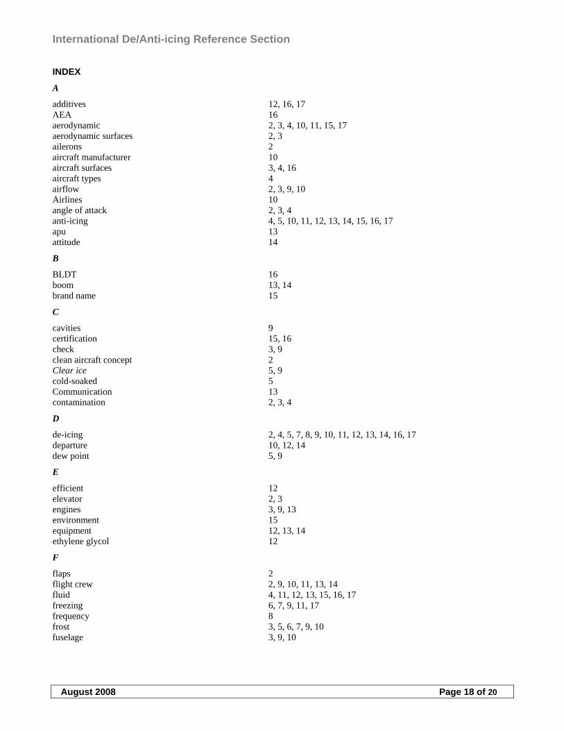
International De/Anti-icing Reference Section
August 2008 Page 18 of 20
INDEX
A
additives 12, 16, 17 AEA 16 aerodynamic 2, 3, 4, 10, 11, 15, 17 aerodynamic surfaces 2, 3 ailerons 2 aircraft manufacturer 10 aircraft surfaces 3, 4, 16 aircraft types 4 airflow 2, 3, 9, 10 Airlines 10 angle of attack 2, 3, 4 anti-icing 4, 5, 10, 11, 12, 13, 14, 15, 16, 17 apu 13 attitude 14
B
BLDT 16 boom 13, 14 brand name 15
C
cavities 9 certification 15, 16 check 3, 9 clean aircraft concept 2 Clear ice 5, 9 cold-soaked 5 Communication 13 contamination 2, 3, 4
D
de-icing 2, 4, 5, 7, 8, 9, 10, 11, 12, 13, 14, 16, 17 departure 10, 12, 14 dew point 5, 9
E
efficient 12 elevator 2, 3 engines 3, 9, 13 environment 15 equipment 12, 13, 14 ethylene glycol 12
F
flaps 2 flight crew 2, 9, 10, 11, 13, 14 fluid 4, 11, 12, 13, 15, 16, 17 freezing 6, 7, 9, 11, 17 frequency 8 frost 3, 5, 6, 7, 9, 10 fuselage 3, 9, 10
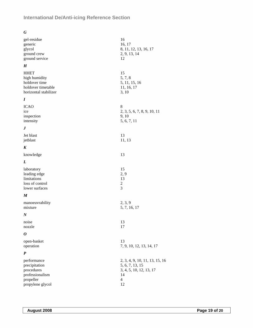
International De/Anti-icing Reference Section
August 2008 Page 19 of 20
G
gel-residue 16 generic 16, 17 glycol 8, 11, 12, 13, 16, 17 ground crew 2, 9, 13, 14 ground service 12
H
HHET 15 high humidity 5, 7, 8 holdover time 5, 11, 15, 16 holdover timetable 11, 16, 17 horizontal stabilizer 3, 10
I
ICAO 8 ice 2, 3, 5, 6, 7, 8, 9, 10, 11 inspection 9, 10 intensity 5, 6, 7, 11
J
Jet blast 13 jetblast 11, 13
K
knowledge 13
L
laboratory 15 leading edge 2, 9 limitations 13 loss of control 2 lower surfaces 3
M
manoeuvrability 2, 3, 9 mixture 5, 7, 16, 17
N
noise 13 nozzle 17
O
open-basket 13 operation 7, 9, 10, 12, 13, 14, 17
P
performance 2, 3, 4, 9, 10, 11, 13, 15, 16 precipitation 5, 6, 7, 13, 15 procedures 3, 4, 5, 10, 12, 13, 17 professionalism 14 propeller 4 propylene glycol 12
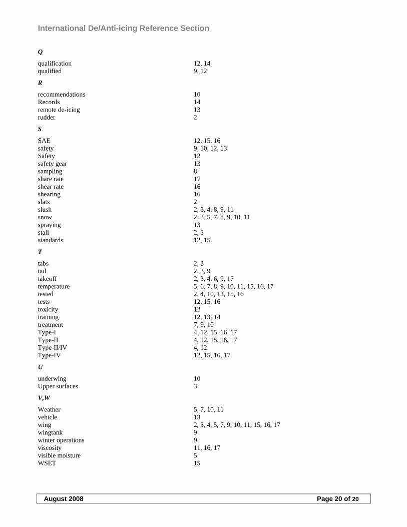
International De/Anti-icing Reference Section
August 2008 Page 20 of 20
Q
qualification 12, 14 qualified 9, 12
R
recommendations 10 Records 14 remote de-icing 13 rudder 2
S
SAE 12, 15, 16 safety 9, 10, 12, 13 Safety 12 safety gear 13 sampling 8 share rate 17 shear rate 16 shearing 16 slats 2 slush 2, 3, 4, 8, 9, 11 snow 2, 3, 5, 7, 8, 9, 10, 11 spraying 13 stall 2, 3 standards 12, 15
T
tabs 2, 3 tail 2, 3, 9 takeoff 2, 3, 4, 6, 9, 17 temperature 5, 6, 7, 8, 9, 10, 11, 15, 16, 17 tested 2, 4, 10, 12, 15, 16 tests 12, 15, 16 toxicity 12 training 12, 13, 14 treatment 7, 9, 10 Type-I 4, 12, 15, 16, 17 Type-II 4, 12, 15, 16, 17 Type-II/IV 4, 12 Type-IV 12, 15, 16, 17
U
underwing 10 Upper surfaces 3
V,W
Weather 5, 7, 10, 11 vehicle 13 wing 2, 3, 4, 5, 7, 9, 10, 11, 15, 16, 17 wingtank 9 winter operations 9 viscosity 11, 16, 17 visible moisture 5 WSET 15
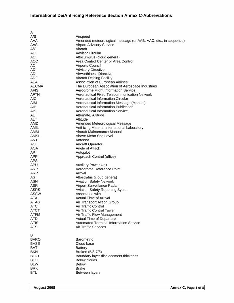
International De/Anti-icing Reference Section Annex C-Abbreviations
August 2008 Annex C, Page 1 of 8
A A/S Airspeed AAA Amended meteorological message (or AAB, AAC, etc., in sequence) AAS Airport Advisory Service A/C Aircraft AC Advisor Circular AC Altocumulus (cloud genera) ACC Area Control Center or Area Control ACI Airports Council AD Advisory Directive AD Airworthiness Directive ADF Aircraft Deicing Facility AEA Association of European Airlines AECMA The European Association of Aerospace Industries AFIS Aerodrome Flight Information Service AFTN Aeronautical Fixed Telecommunication Network AIC Aeronautical Information Circular AIM Aeronautical Information Message (Manual) AIP Aeronautical Information Publication AIS Aeronautical Information Service ALT Alternate, Altitude ALT Altitude AMD Amended Meteorological Message AMIL Anti-icing Material International Laboratory AMM Aircraft Maintenance Manual AMSL Above Mean Sea Level ANT Antenna AO Aircraft Operator AOA Angle of Attack AP Autopilot APP Approach Control (office) APS APU Auxilary Power Unit ARP Aerodrome Reference Point ARR Arrival AS Altostratus (cloud genera) ASN Aviation Safety Network ASR Airport Surveillance Radar ASRS Aviation Safety Reporting System ASSW Associated with ATA Actual Time of Arrival ATAG Air Transport Action Group ATC Air Traffic Control ATCT Air Traffic Control Tower ATFM Air Traffic Flow Management ATD Actual Time of Departure ATIS Automated Terminal Information Service ATS Air Traffic Services B BARO Barometric BASE Cloud base BAT Battery BKN Broken (5/8-7/8) BLDT Boundary layer displacement thickness BLO Below clouds BLW Below... BRK Brake BTL Between layers
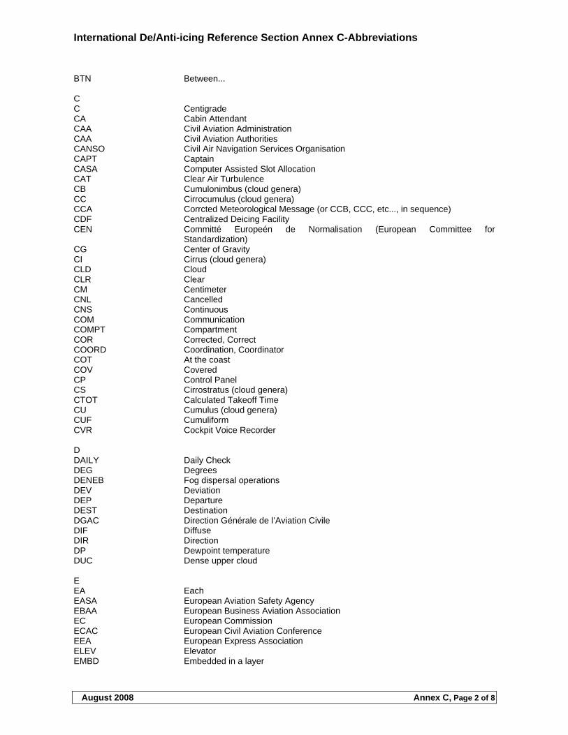
International De/Anti-icing Reference Section Annex C-Abbreviations
August 2008 Annex C, Page 2 of 8
BTN Between... C C Centigrade CA Cabin Attendant CAA Civil Aviation Administration CAA Civil Aviation Authorities CANSO Civil Air Navigation Services Organisation CAPT Captain CASA Computer Assisted Slot Allocation CAT Clear Air Turbulence CB Cumulonimbus (cloud genera) CC Cirrocumulus (cloud genera) CCA Corrcted Meteorological Message (or CCB, CCC, etc..., in sequence) CDF Centralized Deicing Facility CEN Committé Europeén de Normalisation (European Committee for
Standardization) CG Center of Gravity CI Cirrus (cloud genera) CLD Cloud CLR Clear CM Centimeter CNL Cancelled CNS Continuous COM Communication COMPT Compartment COR Corrected, Correct COORD Coordination, Coordinator COT At the coast COV Covered CP Control Panel CS Cirrostratus (cloud genera) CTOT Calculated Takeoff Time CU Cumulus (cloud genera) CUF Cumuliform CVR Cockpit Voice Recorder D DAILY Daily Check DEG Degrees DENEB Fog dispersal operations DEV Deviation DEP Departure DEST Destination DGAC Direction Générale de l’Aviation Civile DIF Diffuse DIR Direction DP Dewpoint temperature DUC Dense upper cloud E EA Each EASA European Aviation Safety Agency EBAA European Business Aviation Association EC European Commission ECAC European Civil Aviation Conference EEA European Express Association ELEV Elevator EMBD Embedded in a layer
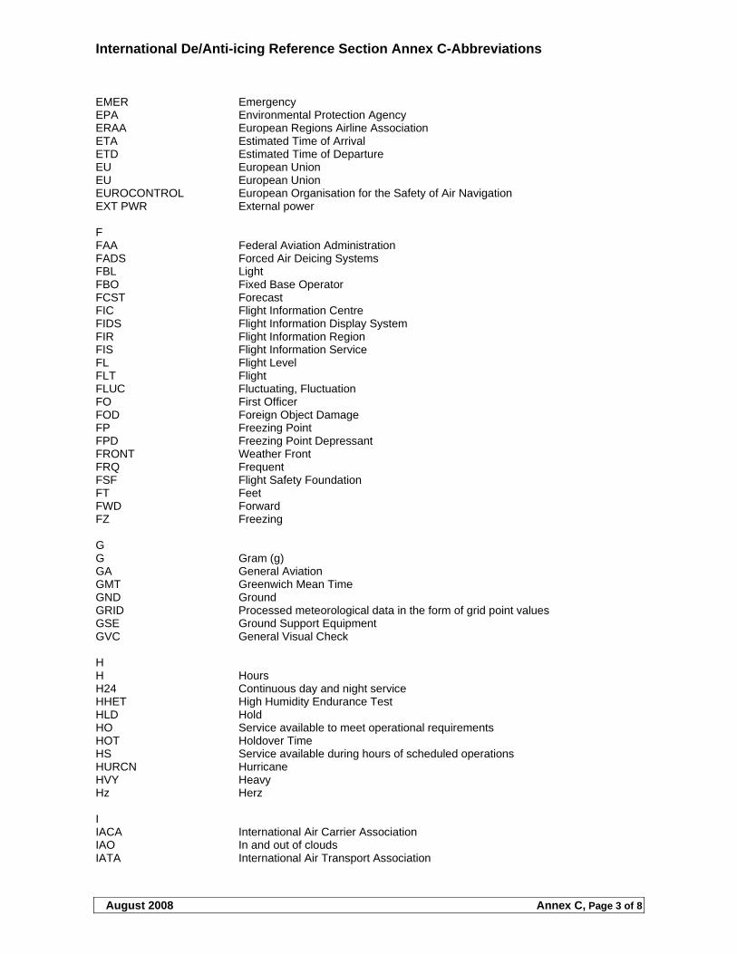
International De/Anti-icing Reference Section Annex C-Abbreviations
August 2008 Annex C, Page 3 of 8
EMER Emergency EPA Environmental Protection Agency ERAA European Regions Airline Association ETA Estimated Time of Arrival ETD Estimated Time of Departure EU European Union EU European Union EUROCONTROL European Organisation for the Safety of Air Navigation EXT PWR External power F FAA Federal Aviation Administration FADS Forced Air Deicing Systems FBL Light FBO Fixed Base Operator FCST Forecast FIC Flight Information Centre FIDS Flight Information Display System FIR Flight Information Region FIS Flight Information Service FL Flight Level FLT Flight FLUC Fluctuating, Fluctuation FO First Officer FOD Foreign Object Damage FP Freezing Point FPD Freezing Point Depressant FRONT Weather Front FRQ Frequent FSF Flight Safety Foundation FT Feet FWD Forward FZ Freezing G G Gram (g) GA General Aviation GMT Greenwich Mean Time GND Ground GRID Processed meteorological data in the form of grid point values GSE Ground Support Equipment GVC General Visual Check H H Hours H24 Continuous day and night service HHET High Humidity Endurance Test HLD Hold HO Service available to meet operational requirements HOT Holdover Time HS Service available during hours of scheduled operations HURCN Hurricane HVY Heavy Hz Herz I IACA International Air Carrier Association IAO In and out of clouds IATA International Air Transport Association
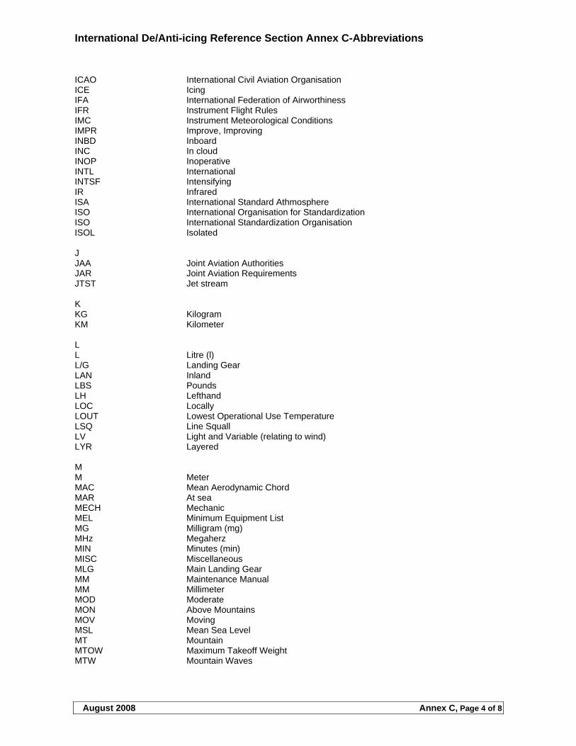
International De/Anti-icing Reference Section Annex C-Abbreviations
August 2008 Annex C, Page 4 of 8
ICAO International Civil Aviation Organisation ICE Icing IFA International Federation of Airworthiness IFR Instrument Flight Rules IMC Instrument Meteorological Conditions IMPR Improve, Improving INBD Inboard INC In cloud INOP Inoperative INTL International INTSF Intensifying IR Infrared ISA International Standard Athmosphere ISO International Organisation for Standardization ISO International Standardization Organisation ISOL Isolated J JAA Joint Aviation Authorities JAR Joint Aviation Requirements JTST Jet stream K KG Kilogram KM Kilometer L L Litre (l) L/G Landing Gear LAN Inland LBS Pounds LH Lefthand LOC Locally LOUT Lowest Operational Use Temperature LSQ Line Squall LV Light and Variable (relating to wind) LYR Layered M M Meter MAC Mean Aerodynamic Chord MAR At sea MECH Mechanic MEL Minimum Equipment List MG Milligram (mg) MHz Megaherz MIN Minutes (min) MISC Miscellaneous MLG Main Landing Gear MM Maintenance Manual MM Millimeter MOD Moderate MON Above Mountains MOV Moving MSL Mean Sea Level MT Mountain MTOW Maximum Takeoff Weight MTW Mountain Waves
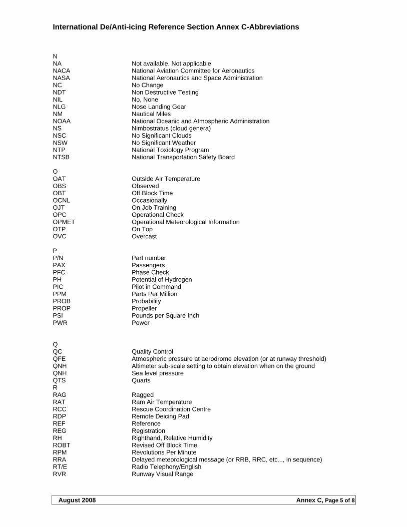
International De/Anti-icing Reference Section Annex C-Abbreviations
August 2008 Annex C, Page 5 of 8
N NA Not available, Not applicable NACA National Aviation Committee for Aeronautics NASA National Aeronautics and Space Administration NC No Change NDT Non Destructive Testing NIL No, None NLG Nose Landing Gear NM Nautical Miles NOAA National Oceanic and Atmospheric Administration NS Nimbostratus (cloud genera) NSC No Significant Clouds NSW No Significant Weather NTP National Toxiology Program NTSB National Transportation Safety Board O OAT Outside Air Temperature OBS Observed OBT Off Block Time OCNL Occasionally OJT On Job Training OPC Operational Check OPMET Operational Meteorological Information OTP On Top OVC Overcast P P/N Part number PAX Passengers PFC Phase Check PH Potential of Hydrogen PIC Pilot in Command PPM Parts Per Million PROB Probability PROP Propeller PSI Pounds per Square Inch PWR Power Q QC Quality Control QFE Atmospheric pressure at aerodrome elevation (or at runway threshold) QNH Altimeter sub-scale setting to obtain elevation when on the ground QNH Sea level pressure QTS Quarts R RAG Ragged RAT Ram Air Temperature RCC Rescue Coordination Centre RDP Remote Deicing Pad REF Reference REG Registration RH Righthand, Relative Humidity ROBT Revised Off Block Time RPM Revolutions Per Minute RRA Delayed meteorological message (or RRB, RRC, etc..., in sequence) RT/E Radio Telephony/English RVR Runway Visual Range
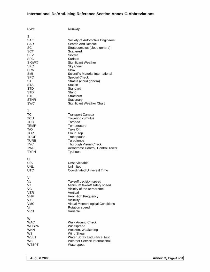
International De/Anti-icing Reference Section Annex C-Abbreviations
August 2008 Annex C, Page 6 of 8
RWY Runway S SAE Society of Automotive Engineers SAR Search And Rescue SC Stratocumulus (cloud genera) SCT Scattered SEV Severe SFC Surface SIGWX Significant Weather SKC Sky Clear SLW Slow SMI Scientific Material International SPC Special Check ST Stratus (cloud genera) STA Station STD Standard STD Stand STF Stratiform STNR Stationary SWC Significant Weather Chart T TC Transport Canada TCU Towering cumulus TDO Tornado TEMP Temperature T/O Take Off TOP Cloud Top TROP Tropopause TURB Turbulence TVC Thorough Visual Check TWR Aerodrome Control, Control Tower TYPH Typhoon U U/S Unserviceable UNL Unlimited UTC Coordinated Universal Time V V1 Takeoff decision speed V2 Minimum takeoff safety speed VC Vicinity of the aerodrome VER Vertical VHF Very High Frequency VIS Visibility VMC Visual Meteorological Conditions Vr Rotation speed VRB Variable W WAC Walk Around Check WDSPR Widespread WKN Weaken, Weakening WS Wind Shear WSET Water Spray Endurance Test WSI Weather Service International WTSPT Waterspout
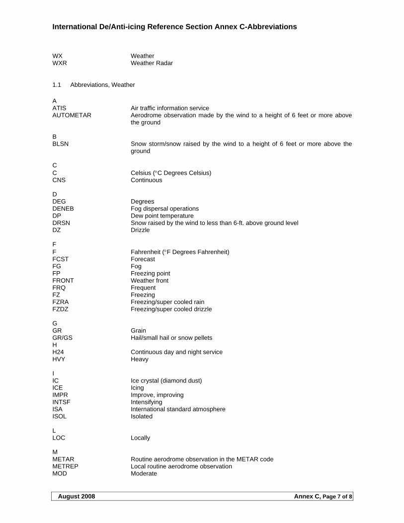
International De/Anti-icing Reference Section Annex C-Abbreviations
August 2008 Annex C, Page 7 of 8
WX Weather WXR Weather Radar
1.1 Abbreviations, Weather
A ATIS Air traffic information service AUTOMETAR Aerodrome observation made by the wind to a height of 6 feet or more above
the ground B BLSN Snow storm/snow raised by the wind to a height of 6 feet or more above the
ground C C Celsius (C Degrees Celsius) CNS Continuous D DEG Degrees DENEB Fog dispersal operations DP Dew point temperature DRSN Snow raised by the wind to less than 6-ft. above ground level DZ Drizzle F F Fahrenheit (F Degrees Fahrenheit) FCST Forecast FG Fog FP Freezing point FRONT Weather front FRQ Frequent FZ Freezing FZRA Freezing/super cooled rain FZDZ Freezing/super cooled drizzle G GR Grain GR/GS Hail/small hail or snow pellets H H24 Continuous day and night service HVY Heavy I IC Ice crystal (diamond dust) ICE Icing IMPR Improve, improving INTSF Intensifying ISA International standard atmosphere ISOL Isolated L LOC Locally M METAR Routine aerodrome observation in the METAR code METREP Local routine aerodrome observation MOD Moderate
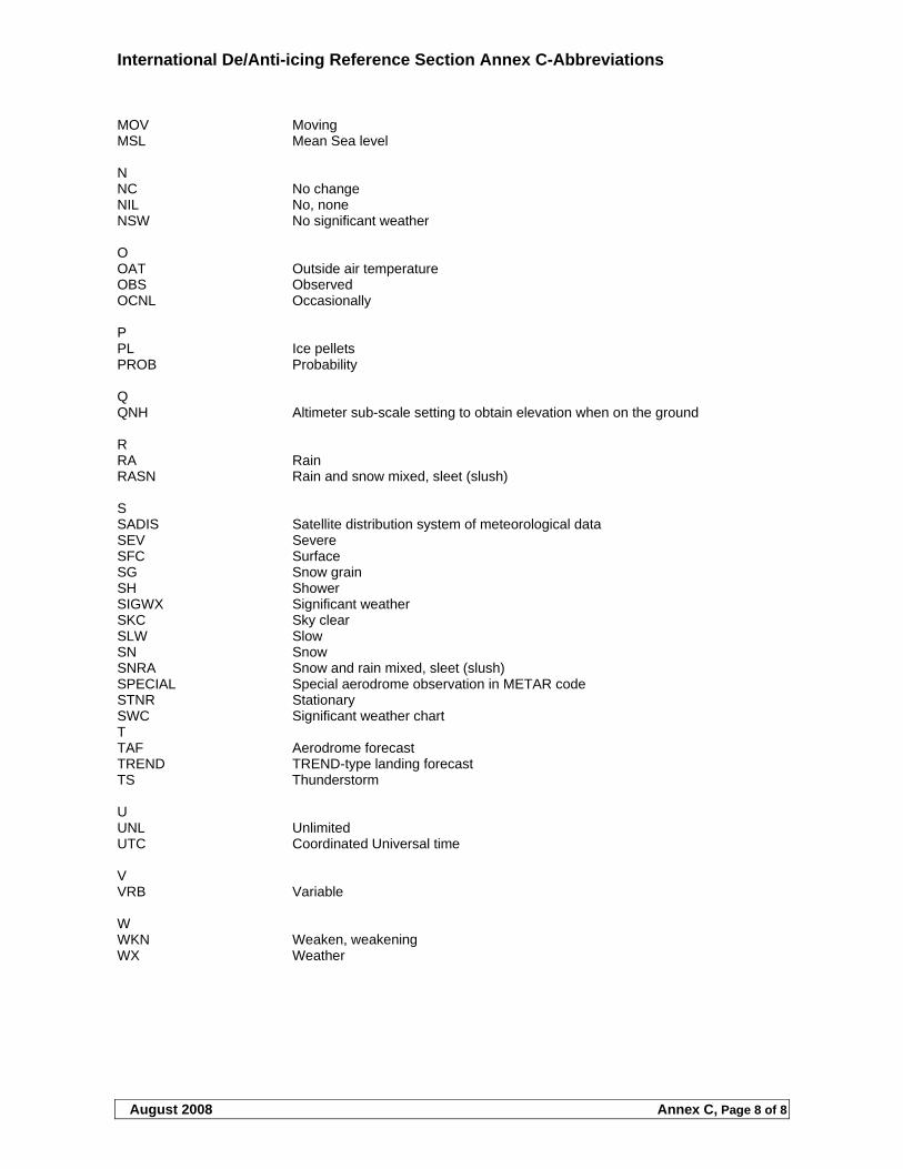
International De/Anti-icing Reference Section Annex C-Abbreviations
August 2008 Annex C, Page 8 of 8
MOV Moving MSL Mean Sea level N NC No change NIL No, none NSW No significant weather O OAT Outside air temperature OBS Observed OCNL Occasionally P PL Ice pellets PROB Probability Q QNH Altimeter sub-scale setting to obtain elevation when on the ground R RA Rain RASN Rain and snow mixed, sleet (slush) S SADIS Satellite distribution system of meteorological data SEV Severe SFC Surface SG Snow grain SH Shower SIGWX Significant weather SKC Sky clear SLW Slow SN Snow SNRA Snow and rain mixed, sleet (slush) SPECIAL Special aerodrome observation in METAR code STNR Stationary SWC Significant weather chart T TAF Aerodrome forecast TREND TREND-type landing forecast TS Thunderstorm U UNL Unlimited UTC Coordinated Universal time V VRB Variable W WKN Weaken, weakening WX Weather
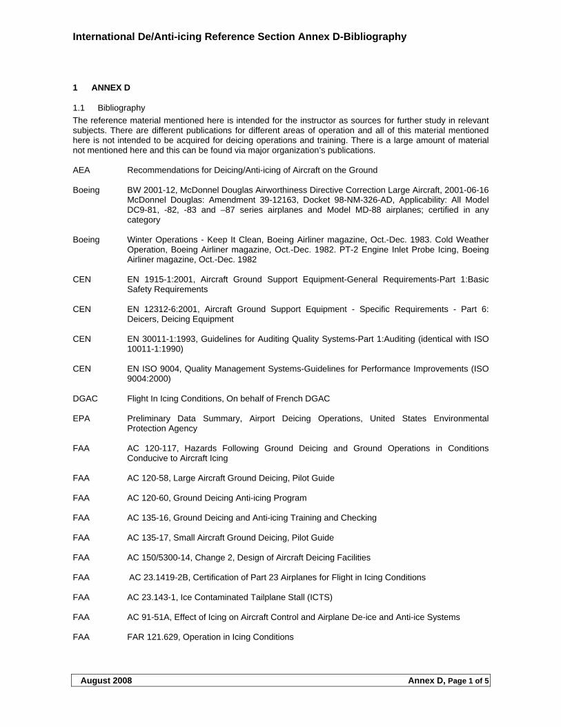
International De/Anti-icing Reference Section Annex D-Bibliography
August 2008 Annex D, Page 1 of 5
1 ANNEX D
1.1 Bibliography
The reference material mentioned here is intended for the instructor as sources for further study in relevant subjects. There are different publications for different areas of operation and all of this material mentioned here is not intended to be acquired for deicing operations and training. There is a large amount of material not mentioned here and this can be found via major organization’s publications. AEA Recommendations for Deicing/Anti-icing of Aircraft on the Ground Boeing BW 2001-12, McDonnel Douglas Airworthiness Directive Correction Large Aircraft, 2001-06-16
McDonnel Douglas: Amendment 39-12163, Docket 98-NM-326-AD, Applicability: All Model DC9-81, -82, -83 and –87 series airplanes and Model MD-88 airplanes; certified in any category
Boeing Winter Operations - Keep It Clean, Boeing Airliner magazine, Oct.-Dec. 1983. Cold Weather
Operation, Boeing Airliner magazine, Oct.-Dec. 1982. PT-2 Engine Inlet Probe Icing, Boeing Airliner magazine, Oct.-Dec. 1982
CEN EN 1915-1:2001, Aircraft Ground Support Equipment-General Requirements-Part 1:Basic
Safety Requirements CEN EN 12312-6:2001, Aircraft Ground Support Equipment - Specific Requirements - Part 6:
Deicers, Deicing Equipment CEN EN 30011-1:1993, Guidelines for Auditing Quality Systems-Part 1:Auditing (identical with ISO
10011-1:1990) CEN EN ISO 9004, Quality Management Systems-Guidelines for Performance Improvements (ISO
9004:2000) DGAC Flight In Icing Conditions, On behalf of French DGAC EPA Preliminary Data Summary, Airport Deicing Operations, United States Environmental
Protection Agency FAA AC 120-117, Hazards Following Ground Deicing and Ground Operations in Conditions
Conducive to Aircraft Icing FAA AC 120-58, Large Aircraft Ground Deicing, Pilot Guide FAA AC 120-60, Ground Deicing Anti-icing Program FAA AC 135-16, Ground Deicing and Anti-icing Training and Checking FAA AC 135-17, Small Aircraft Ground Deicing, Pilot Guide FAA AC 150/5300-14, Change 2, Design of Aircraft Deicing Facilities FAA AC 23.1419-2B, Certification of Part 23 Airplanes for Flight in Icing Conditions FAA AC 23.143-1, Ice Contaminated Tailplane Stall (ICTS) FAA AC 91-51A, Effect of Icing on Aircraft Control and Airplane De-ice and Anti-ice Systems FAA FAR 121.629, Operation in Icing Conditions
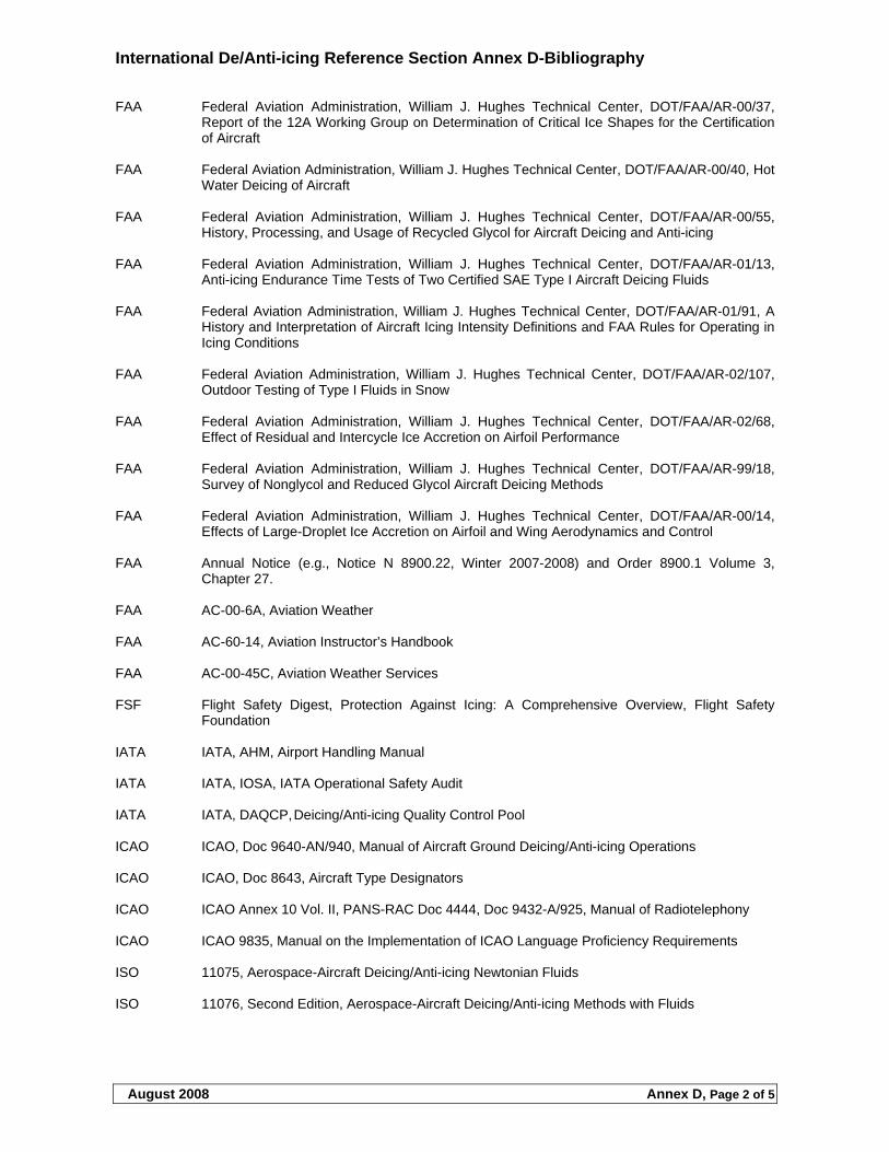
International De/Anti-icing Reference Section Annex D-Bibliography
August 2008 Annex D, Page 2 of 5
FAA Federal Aviation Administration, William J. Hughes Technical Center, DOT/FAA/AR-00/37, Report of the 12A Working Group on Determination of Critical Ice Shapes for the Certification of Aircraft
FAA Federal Aviation Administration, William J. Hughes Technical Center, DOT/FAA/AR-00/40, Hot
Water Deicing of Aircraft FAA Federal Aviation Administration, William J. Hughes Technical Center, DOT/FAA/AR-00/55,
History, Processing, and Usage of Recycled Glycol for Aircraft Deicing and Anti-icing FAA Federal Aviation Administration, William J. Hughes Technical Center, DOT/FAA/AR-01/13,
Anti-icing Endurance Time Tests of Two Certified SAE Type I Aircraft Deicing Fluids FAA Federal Aviation Administration, William J. Hughes Technical Center, DOT/FAA/AR-01/91, A
History and Interpretation of Aircraft Icing Intensity Definitions and FAA Rules for Operating in Icing Conditions
FAA Federal Aviation Administration, William J. Hughes Technical Center, DOT/FAA/AR-02/107,
Outdoor Testing of Type I Fluids in Snow FAA Federal Aviation Administration, William J. Hughes Technical Center, DOT/FAA/AR-02/68,
Effect of Residual and Intercycle Ice Accretion on Airfoil Performance FAA Federal Aviation Administration, William J. Hughes Technical Center, DOT/FAA/AR-99/18,
Survey of Nonglycol and Reduced Glycol Aircraft Deicing Methods FAA Federal Aviation Administration, William J. Hughes Technical Center, DOT/FAA/AR-00/14,
Effects of Large-Droplet Ice Accretion on Airfoil and Wing Aerodynamics and Control FAA Annual Notice (e.g., Notice N 8900.22, Winter 2007-2008) and Order 8900.1 Volume 3,
Chapter 27. FAA AC-00-6A, Aviation Weather FAA AC-60-14, Aviation Instructor’s Handbook FAA AC-00-45C, Aviation Weather Services FSF Flight Safety Digest, Protection Against Icing: A Comprehensive Overview, Flight Safety
Foundation IATA IATA, AHM, Airport Handling Manual IATA IATA, IOSA, IATA Operational Safety Audit IATA IATA, DAQCP, Deicing/Anti-icing Quality Control Pool ICAO ICAO, Doc 9640-AN/940, Manual of Aircraft Ground Deicing/Anti-icing Operations ICAO ICAO, Doc 8643, Aircraft Type Designators ICAO ICAO Annex 10 Vol. II, PANS-RAC Doc 4444, Doc 9432-A/925, Manual of Radiotelephony ICAO ICAO 9835, Manual on the Implementation of ICAO Language Proficiency Requirements ISO 11075, Aerospace-Aircraft Deicing/Anti-icing Newtonian Fluids ISO 11076, Second Edition, Aerospace-Aircraft Deicing/Anti-icing Methods with Fluids
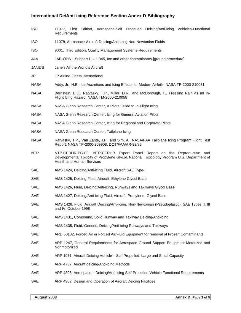
International De/Anti-icing Reference Section Annex D-Bibliography
August 2008 Annex D, Page 3 of 5
ISO 11077, First Edition, Aerospace-Self Propelled Deicing/Anti-icing Vehicles-Functional Requirements
ISO 11078, Aerospace-Aircraft Deicing/Anti-icing Non-Newtonian Fluids ISO 9001, Third Edition, Quality Management Systems-Requirements JAA JAR-OPS 1 Subpart D – 1.345, Ice and other contaminants-[ground procedure] JANE’S Jane’s All the World’s Aircraft JP JP Airline-Fleets International NASA Addy, Jr,. H.E., Ice Accretions and Icing Effects for Modern Airfoils, NASA TP-2000-210031 NASA Bernstein, B.C., Ratvasky, T.P., Miller, D.R., and McDonough, F., Freezing Rain as an In-
Flight Icing Hazard, NASA TM-2000-210058 NASA NASA Glenn Research Center, A Pilots Guide to In-Flight Icing NASA NASA Glenn Research Center, Icing for General Aviation Pilots NASA NASA Glenn Research Center, Icing for Regional and Corporate Pilots NASA NASA Glenn Research Center, Tailplane Icing NASA Ratvasky, T.P., Van Zante, J.F., and Sim, A., NASA/FAA Tailplane Icing Program:Flight Test
Report, NASA TP-2000-209908, DOT/FAA/AR-99/85 NTP NTP-CERHR-PG-03, NTP-CERHR Expert Panel Report on the Reproductive and
Developmental Toxicity of Propylene Glycol, National Toxicology Program U.S. Department of Health and Human Services
SAE AMS 1424, Deicing/Anti-icing Fluid, Aircraft SAE Type-I SAE AMS 1425, Deicing Fluid, Aircraft, Ethylene Glycol Base SAE AMS 1426, Fluid, Deicing/Anti-icing, Runways and Taxiways Glycol Base SAE AMS 1427, Deicing/Anti-icing Fluid, Aircraft, Propylene- Glycol Base SAE AMS 1428, Fluid, Aircraft Deicing/Anti-icing, Non-Newtonian (Pseudoplastic), SAE Types II, III
and IV, October 1998 SAE AMS 1431, Compound, Solid Runway and Taxiway Deicing/Anti-icing SAE AMS 1435, Fluid, Generic, Deicing/Anti-icing Runways and Taxiways SAE ARD 50102, Forced Air or Forced Air/Fluid Equipment for removal of Frozen Contaminants SAE ARP 1247, General Requirements for Aerospace Ground Support Equipment Motorized and
Nonmotorized SAE ARP 1971, Aircraft Deicing Vehicle – Self Propelled, Large and Small Capacity SAE ARP 4737, Aircraft deicing/Anti-icing Methods SAE ARP 4806, Aerospace – Deicing/Anti-icing Self-Propelled Vehicle Functional Requirements SAE ARP 4902, Design and Operation of Aircraft Deicing Facilities
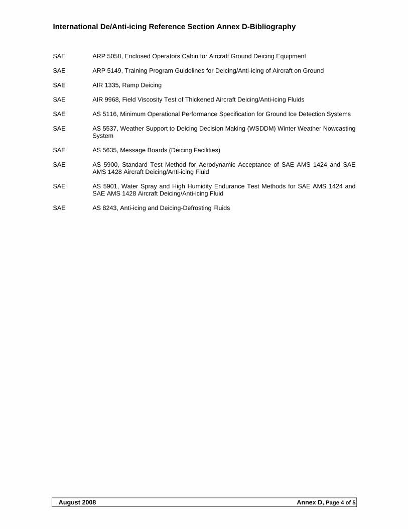
International De/Anti-icing Reference Section Annex D-Bibliography
August 2008 Annex D, Page 4 of 5
SAE ARP 5058, Enclosed Operators Cabin for Aircraft Ground Deicing Equipment SAE ARP 5149, Training Program Guidelines for Deicing/Anti-icing of Aircraft on Ground SAE AIR 1335, Ramp Deicing SAE AIR 9968, Field Viscosity Test of Thickened Aircraft Deicing/Anti-icing Fluids SAE AS 5116, Minimum Operational Performance Specification for Ground Ice Detection Systems SAE AS 5537, Weather Support to Deicing Decision Making (WSDDM) Winter Weather Nowcasting
System SAE AS 5635, Message Boards (Deicing Facilities) SAE AS 5900, Standard Test Method for Aerodynamic Acceptance of SAE AMS 1424 and SAE
AMS 1428 Aircraft Deicing/Anti-icing Fluid SAE AS 5901, Water Spray and High Humidity Endurance Test Methods for SAE AMS 1424 and
SAE AMS 1428 Aircraft Deicing/Anti-icing Fluid SAE AS 8243, Anti-icing and Deicing-Defrosting Fluids
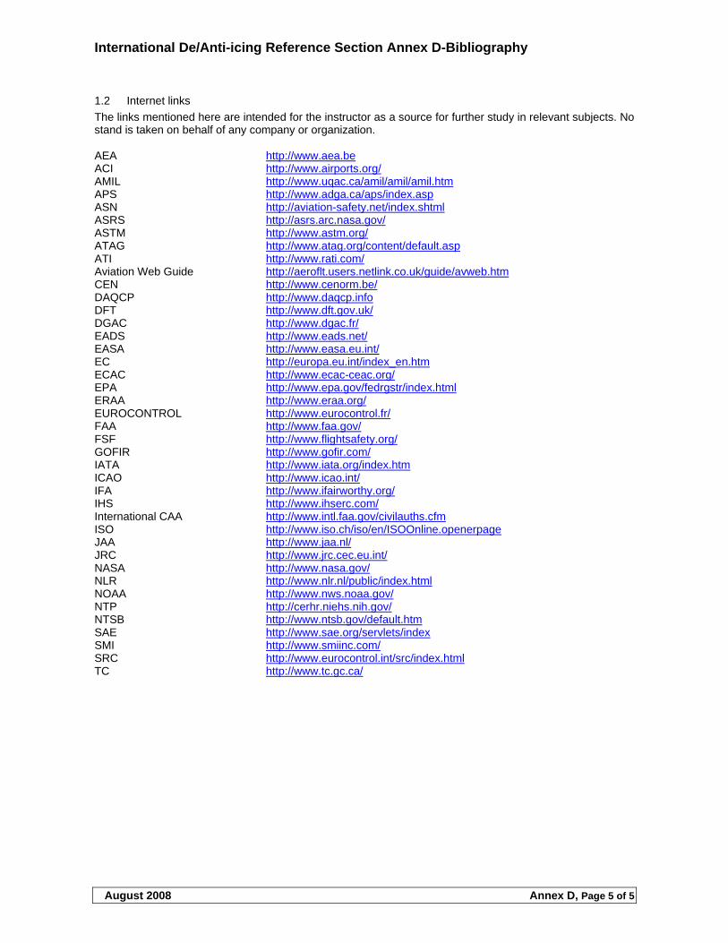
International De/Anti-icing Reference Section Annex D-Bibliography
August 2008 Annex D, Page 5 of 5
1.2 Internet links
The links mentioned here are intended for the instructor as a source for further study in relevant subjects. No stand is taken on behalf of any company or organization. AEA http://www.aea.be ACI http://www.airports.org/ AMIL http://www.uqac.ca/amil/amil/amil.htm APS http://www.adga.ca/aps/index.asp ASN http://aviation-safety.net/index.shtml ASRS http://asrs.arc.nasa.gov/ ASTM http://www.astm.org/ ATAG http://www.atag.org/content/default.asp ATI http://www.rati.com/ Aviation Web Guide http://aeroflt.users.netlink.co.uk/guide/avweb.htm CEN http://www.cenorm.be/ DAQCP http://www.daqcp.info DFT http://www.dft.gov.uk/ DGAC http://www.dgac.fr/ EADS http://www.eads.net/ EASA http://www.easa.eu.int/ EC http://europa.eu.int/index_en.htm ECAC http://www.ecac-ceac.org/ EPA http://www.epa.gov/fedrgstr/index.html ERAA http://www.eraa.org/ EUROCONTROL http://www.eurocontrol.fr/ FAA http://www.faa.gov/ FSF http://www.flightsafety.org/ GOFIR http://www.gofir.com/ IATA http://www.iata.org/index.htm ICAO http://www.icao.int/ IFA http://www.ifairworthy.org/ IHS http://www.ihserc.com/ International CAA http://www.intl.faa.gov/civilauths.cfm ISO http://www.iso.ch/iso/en/ISOOnline.openerpage JAA http://www.jaa.nl/ JRC http://www.jrc.cec.eu.int/ NASA http://www.nasa.gov/ NLR http://www.nlr.nl/public/index.html NOAA http://www.nws.noaa.gov/ NTP http://cerhr.niehs.nih.gov/ NTSB http://www.ntsb.gov/default.htm SAE http://www.sae.org/servlets/index SMI http://www.smiinc.com/ SRC http://www.eurocontrol.int/src/index.html TC http://www.tc.gc.ca/