Internal Inspection of Flow Coating Pipelines · internal flow coating of pipes and when they slide...
16
19 th World Conference on Non-Destructive Testing 2016 1 License: http://creativecommons.org/licenses/by/3.0/ Internal Inspection of Flow Coating Pipelines Igor ARTEMYEV 1 , Alexsandr KOVALENKO 1 , Zakhar KLYUEV 1 1 RII MSIA SPECTRUM, Moscow, Russia Contact e-mail: [email protected]; [email protected] Abstract. The method of magnetic flux leakage (MFL) is widely used in running pipelines to detect the internal and external corrosion. The special testing device (flaw detector), designed on the basis of MFL method, provides magnetization of ferromagnetic material of the pipe wall. After that the magnetic flux leakage can be recorded by Hall-effect sensors. The defects in the pipe wall are detected on the basis of information received from the Hall-effect sensors. The metal brushes, so called distance keeping elements, are used in order to enter the magnetic field inside the pipe wall and to reduce magnetic field leakage in the air gap. As the energy- saving technologies are applied in pipeline transportation, the special pipes with internal flow coating are used now in pipeline construction. According to the calculations this coating reduces power consumption for gas transportation by 10…15 %. Such technologies were used for gas piping in Gryazovets–Vyborg area and for pipe laying on the seabed of the Baltic Sea, known as the North stream. The application of the flow coating pipes led to the necessity to develop and produce the new tools for internal non-destructive testing, which should not damage the internal pipe coating during testing. In order to keep the internal coating safe and sound, the metal parts of flaw detector should not contact or influence the internal flow coating of pipes. All the parts of the flaw detector, which are in direct contact with the internal flow coating of pipes and when they slide in it, they should be made of polyurethane with Shore hardness of 90 units. The design of flaw detector should not cause chips and scratches on the surface of the internal flow coating. The article describes the issues of development of internal flaw detector, that is the device of longitudinal magnetization, for detection of corrosion and transverse defects, such as ”cracks”, in the walls and weld transverse seams of gas and oil pipelines with internal flow coating, the wall thickness is up to 41 mm and the working pressure is up to 25 MPa. More info about this article: http://ndt.net/?id=19466
Transcript of Internal Inspection of Flow Coating Pipelines · internal flow coating of pipes and when they slide...
19th
World Conference on Non-Destructive Testing 2016
1 License: http://creativecommons.org/licenses/by/3.0/
Internal Inspection of Flow Coating Pipelines
Igor ARTEMYEV 1
, Alexsandr KOVALENKO 1
, Zakhar KLYUEV 1
1 RII MSIA SPECTRUM, Moscow, Russia
Contact e-mail: [email protected]; [email protected]
Abstract. The method of magnetic flux leakage (MFL) is widely used in running
pipelines to detect the internal and external corrosion. The special testing device
(flaw detector), designed on the basis of MFL method, provides magnetization of
ferromagnetic material of the pipe wall. After that the magnetic flux leakage can be
recorded by Hall-effect sensors. The defects in the pipe wall are detected on the
basis of information received from the Hall-effect sensors. The metal brushes, so
called distance keeping elements, are used in order to enter the magnetic field inside
the pipe wall and to reduce magnetic field leakage in the air gap. As the energy-
saving technologies are applied in pipeline transportation, the special pipes with
internal flow coating are used now in pipeline construction. According to the
calculations this coating reduces power consumption for gas transportation by
10…15 %. Such technologies were used for gas piping in Gryazovets–Vyborg area
and for pipe laying on the seabed of the Baltic Sea, known as the North stream. The
application of the flow coating pipes led to the necessity to develop and produce the
new tools for internal non-destructive testing, which should not damage the internal
pipe coating during testing. In order to keep the internal coating safe and sound, the
metal parts of flaw detector should not contact or influence the internal flow coating
of pipes. All the parts of the flaw detector, which are in direct contact with the
internal flow coating of pipes and when they slide in it, they should be made of
polyurethane with Shore hardness of 90 units. The design of flaw detector should
not cause chips and scratches on the surface of the internal flow coating. The article
describes the issues of development of internal flaw detector, that is the device of
longitudinal magnetization, for detection of corrosion and transverse defects, such as
”cracks”, in the walls and weld transverse seams of gas and oil pipelines with
internal flow coating, the wall thickness is up to 41 mm and the working pressure is
up to 25 MPa.
More info about this article: http://ndt.net/?id=19466
2
Introduction
With application of energy-saving technologies in pipeline transportation, the pipes with in-
tube flow coatings are used now. Such coating reduces energy costs for gas transportation
by approximately 10 -15 %. The similar technologies were applied for construction of
pipeline Gryazovets -Vyborg and for laying the pipeline in the Baltic Sea - the North
Stream. The application of new technology of flow coating led to the necessity of the
development and production of new devices for nondestructive testing, which would not
damage the in-tube surface during testing. Lets’ consider the main aspects in design of
corrosion flaw detector for in-line control of flow coating pipelines.
The main requirements for in-line flaw detector for inspection of flow coating pipeline,
determined by the customer, were the following:
- flaw detector is designed for in-line diagnostics (inspection) of technical condition
of pipes during gas transportation; the nominal outside pipe diameter Dnom = 1420 mm; wall
thickness is from 21.6 to 32.0 mm, with in-tube flow coating; working pressures is up to
12.5 MPa;
- transported gas is dry natural gas with at least 98 % of methane, sulfur free
(without H2S), with low content of CO2. . Dust level of transported gas is less than 5 mg /
sq.m.. The flow rate inside the pipeline during cleaning and inspection is up to 4 m/sec.
Internal flow coating should meet the requirements of STO Gazprom 2-2.2-180-2007
«Technical requirements for flow coatings for construction of trunk pipelines."
The system components should meet the requirements of standard- GOST R 51330
(IEC 60079) by level and types of security.
Tasks to be solved by the development:
• detection and identification of defects in the pipe base metal:
- corrosion defects,
- mechanical damages,
- cavities, pitting, transverse grooves, transverse cracks,
- metallurgical defects,
• detection of girth weld anomalies,
• detection of constructive elements of the pipeline, repair parts and metal parts inside
the pipe or metal objects touching the pipe from the outside,
• achievement of high reliability of identification and determination of defect
parameters with detection probability 90 %.
3
1. Requirements for flaw detector
The flaw detector is designed to be use at gas pipelines with the characteristics listed below.
Technical specification of flaw detector for gas pipelines
Material of pipe wall should match the steel grades, strength class K42 –
K60 or equivalent
Dust level of transported gas, mg/m3 not more than 5
Internal flow coating according to STO Gazprom 2-2.2-180-2007
Max ovality of the tube 0,1 Dnom
Height of roughness on the inner surface of the pipe
wall, mm
up to 3
Edges shifting and weld seam strengthening, mm 0,5-0,3
Minimum pipeline turning radius 2,5 Dnom
Range of the wall thickness of the inspected pipeline,
mm
21,6 - 32,0
Linear stop valve Flush
Pipe-bends Closed by protective gratings
Slopes (rise and descent angles of the pipe on the
area..According to SNiP 02.05.06–85* "Trunk
pipelines" Distance between neighboring marker
pips, m
not more than 2000
In order to save the integrity of in-tube coating:
− metal parts of flaw detector should not contact or influence the internal flow
coating of the pipe;
− all the elements of flaw detector which are in direct contact with the internal
smooth surface of the pipes and slide inside, should be made of polyurethane with Shore
hardness 90 units;
− the design of the system components should not make chips and scratches on the
in-tube flow surface;
− the thickness of the coating after first and subsequent usage of flow detector and
its elements (not less than 30 cycles) should not come down the lower limit of thickness,
specified in the STO Gazprom 2-2.2-180 -2007 (should be verified at the stand);
− the roughness of in-tube coating after first and subsequent usage of flow detector
and its elements (not less than 30 cycles) should not exceed the roughness, specified in the
STO Gazprom 2-2.2-180 -2007 (should be verified at the stand);
− contact pressure of the shells on the internal coating in the case of dry friction
should not exceed 20 N /cm 2;
− sensitivity of the new devices should not be worse than the sensitivity of similar
instruments, given in "Temporary technical requirements for diagnostic equipment for in-
line flaw detection" by R Gazprom.
Flaw detector should identify [1-3]:
− defects of the pipe base metal, given in Fig. 1;
− weld seam defects, given in Fig. 2.

4
Defects of pipe base metal
Corrosion defects A Mechanical defects B Cracks C Metallurgical defects D
General corrosion Aa Scratch Ba Single cracks Ca Foliation Da
Cavity Ab Grinding Bb Cracks colony (stress-
corrosion cracking) Cb
Rolled metal defects Db
Pitting Ac Dent Gd Cracks colony (hydrogen
attack) Cc
Longitudinal groove Ad
Transverse groove Ae Fig. 1 Defects of pipe base metal
Weld seam defects
Girth weld defects Ea Manufacturing weld seam defects
Edges shifting Ea Grinding Fa
Shrinkage cavity Eb Seam shape problem Fb
Crack Ec Crack Fc
Rolled kink Ed
Shrinkage groove Ee Fig. 2 Weld seam defects
2. Operating and dimensional characteristics of flaw detector
Operating speeds range of flaw detector, m/s..........................................................0,5...4,0
Speed range of transported gas, m/sec…………………………………………….0,5...4,0
Pressure range, MPa.................................................................................................2,0...12,5
Active speed control device ……………………………………………………….No
Operating temperature range, °C……………………………………..................... -10...+ 50
Magnetic field strength in control area, kA/m, not less than………………........... 15
Minimum turning radius of pipeline………………………………………………2,5 Dnom
Minimum internal diameter, overcome by the shell............................................... 0,85
Dnom
Shell mass, kg, not more than……………………………………………….......... 9000
Shell length, mm, not more than………………………………………………...... 5000
Maximum length of the inspected pipeline in a single shell pass, km,………….. 300
Scanning step of the main sensor system along the axis of the pipe, mm, not more
than.............. 5
The distance between sensors around the circumference, mm, not more than…………5
Magnetic system of the shell…………………………………………...……….. Contactless
Requirements to accuracy of determination of geometrical parameters and minimum depth
of detected defects of pipes are given in Table 1.
Table 1. Requirements to accuracy of determination of geometrical parameters and minimum depth of
detected defects of pipes
Accuracy of determination of
geometrical parameters of defect
with 80% confidence Defect
Minimal depth of the
defect, identified at the
confidence level 90 %
(POD) Depth Length, mm Width, mm
General corrosion 0,05 t ± 0,1 t ± 30 ± 30
Cavity 0,1 t ± 0,12 t ± 20 ± 30
Pitting 0,2 t ± 0,2 t ± 15 ± 30
Longitudinal 0,2 t ± 0,2 t ± 20 ± 30

5
Accuracy of determination of
geometrical parameters of defect
with 80% confidence
groove
Transverse groove 0,1 t ± 0,12 t ± 20 ± 30
t - thickness of pipe wall.
Table 2. Requirements to the accuracy of determination of geometric parameters and minimum depth of detected
weld seam defects
Accuracy of
determination of
geometrical parameters
of defect
with 80% confidence Type of defect
Kind
of defect
Defect length*
α, mm
Minimal equivalent depth of
the defect, identified at the
confidence level 90 % (POD)
Depth Length*,
mm
Edges
shifting Ea
L> 1/6
of weld
perimeter
± 0,2 t ± 0,2 t ± 60
Shrinkage
cavity Eb
L> 80 mm ± 0,2 t ± 0,15 t ± 30
Crack Ec > 80 ± 0,25 t ± 0,2 t ± 30
Rolled kink
Ed > 80 ± 0,25 t ± 0,15 t ± 30
Shape defects
Shrinkage
groove Ee > 50 ± 0,2 t ± 0,1 t ± 30
Grinding Fa > 50 ± 0,1 t no ± 30
Seam shape
problem Fb > 50 ± 0,2 t ± 0, 15 t ± 30
Manufacturing
defects of
spiral weld
seams F Crack Fc > 80 ± 0,2 t ± 0,2 t ± 30
∗ defect length is measured along the axis of the weld seam
During the detection and measurement of weld defects the following conditions are
met:
• flaw detection technology should provide the identification of weld seam defects
with equivalent depth of more than 0.3 t. Defect size is estimated in true depth
• if equivalent depth of weld seam defects is less than 0.3 t, defect is identified as an
anomaly. Defect size is estimated in equivalent depth unit;
• estimation of the weld seam defect length is made according to the measurement
threshold. The measurement threshold is assumed as equal to the detection threshold
when the POD is 90% + 0,05 t;
• estimation of the weld seam defect width is not performed.
Requirements to the accuracy of determination of geometric parameters and
minimum depth of detected weld seam defects are given in Table 2.
• Flaw detector should identify the constructive elements of the pipeline:
• pipes, embedded coils, segment insertions;
• curved insertions (bends);
• block valve stations;
6
• fittings;
• tee pipes;
• branch –incut;
• welding-up of manufacturing windows and holes;
• repair joints (metal);
Flaw detector should detect the pipeline elements:
• protective housings (cartridges) across the road;
• housing (cartridge) eccentricity;
• cantledges (clamp and ring cast iron);
• metal objects touching the pipe of the gas pipeline from the outside;
• MC welding places (Requirements for the probability of detection of MC welding
places (Measurement column) electrochemical protection systems (ECPS) are fixed
at level 50 � POI � 70);
• passive marker pads.
Defectoscopy technology should provide the probability of identification of pipeline
defects, detected by flaw detector, according to the table 3.
Flaw detector should be able to determine the location (coordinates) of the defects
(defective areas) along the pipeline (pipe length) and by location of angle section of the
tube. The error in determination of location (coordinates) of the defects (defective area)
should not be less than the following:
− distance error along the longitudinal axis from the reference point (benchmark)
(distance between markers (reference points) to 2000 m) ……………………… ± 0,2 %;
− distance error along the longitudinal axis of the girth weld…………… … ± 20 mm;
− orientation error……………………………………………………………….. ± 6°;
− thickness error in the pipe wall……………………………………………….. ± 5%;
− length error of the tube ………………………………..…..………. ± 20 mm.
Flaw detector servicing before and after running is allowed at the temperature from
-10 to +50°� and atmosphere pressure from 0,8 ⋅ 105 to 1,07 ⋅ 10
5 Pa (from 630 to 780
mmHg), relative humidity 30% (95% at 35°�).
Flaw detector should be packed in separate transportation box with gross weight not
more than 10 000 kg.
Dimensions of the packages should allow its transportation in one board-vehicle.
Acceptance of flaw detector is performed during two-step acceptance testing:
• on a special stand-simulator of the pipeline, consisting of pipes with
diameter of 1420 mm and wall thickness of 32 mm, with in-tube flow
coating, with artificial defects on the tube;
• at the site of the operating gas pipeline with in-tube flow coating.
In order to perform acceptance tests it is necessary to develop the program of creation of
artificial defects on the external surface of the stand pipe, the program and methods of
acceptance tests.
The program of the creation of artificial defects on the external surface of the stand pipe
should contain the technology and sequence how to create artificial defects on stand pipe,
artificial defects classification and geometrical parameters.
Created defects should be measured by certified means of external non-destructive
testing, and on the basis of these results the album of defects should be made.
7
Table 3. The probability of identification of defects (POI)
Designation
of defect
class
�lass of defects POI, %
� Corrosion defects:
�� general corrosion POI > 90
�b cavity POI > 90
�� pitting POI > 90
�d longitudinal groove 50 � POI � 70
�� transverse groove POI > 90
� Mechanical damage:
�� scoring POI > 90
�b grinding POI > 90
� Cracks:
single transverse crack POI > 90 ��
transverse crack in girth weld
zone 70 � POI � 90
D Metallurgical defects:
Db Rolled metal defects POI > 90
� Defects of girth weld:
�� edges shifting 70 � POI � 90
�b Shrinkage cavity 70 � POI � 90
�� crack 70 � POI � 90
Ed rolled kink 70 � POI � 90
�� Shrinkage groove 70 � POI � 90
G Shape defects of pipeline:
Gd dent or corrugation POI 90
Program and methods of acceptance tests should be subject to the testing of the system
components at the stand and at the site of the operating pipeline, and verification of all
parameters, stated in the technical specifications, should be provided, as well as the
arrangement of special events associated with the peculiarities of the testing object (wall
thickness of 21.6 ... 32.0 mm, the internal flow coating, including the possibility of its
delamination in the girth weld zone):
- measuring of the pipe wall magnetization during flaw detector running;
- after cleaning and defectoscopy the following places should be inspected for
markings of internal flow coating material:
• system components;
• dust collectors of compressor stations;
• natural gas (chemical composition).
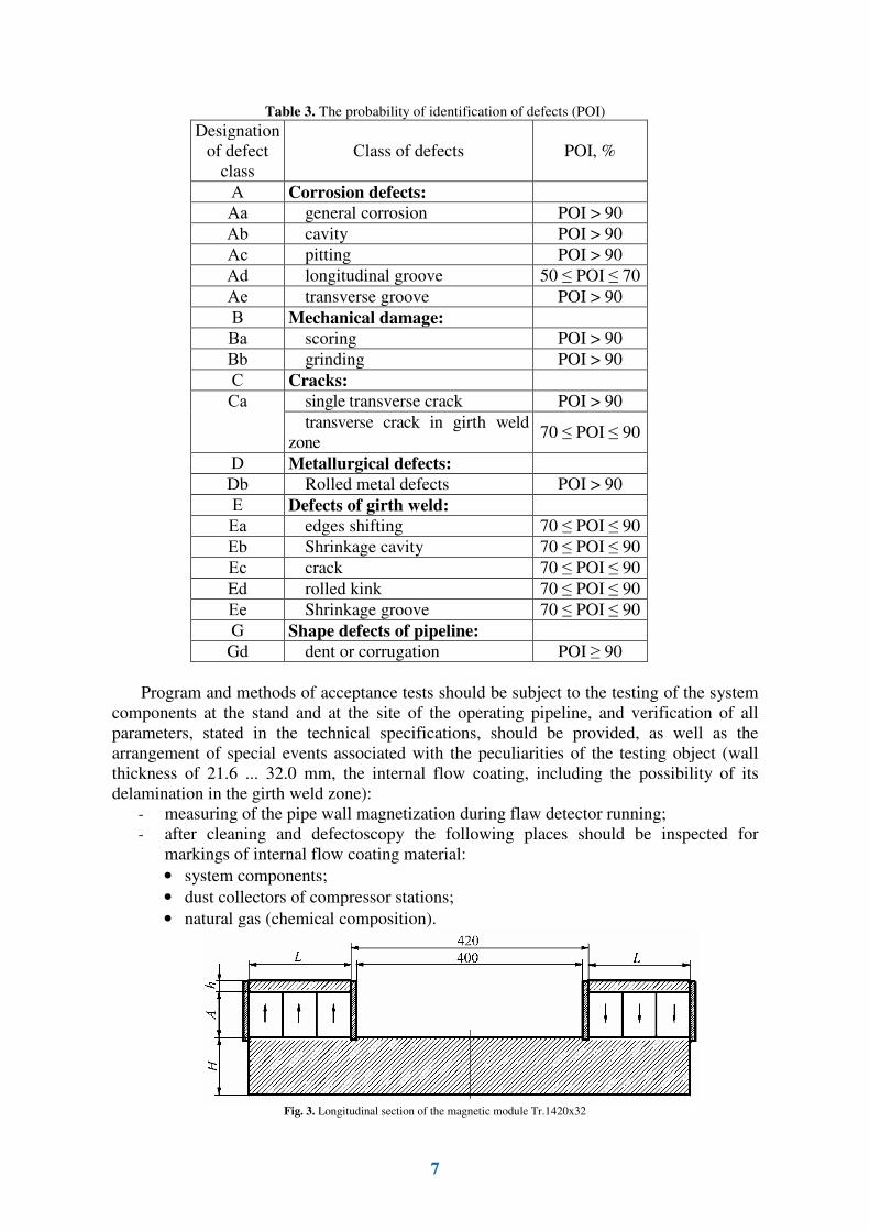
Fig. 3. Longitudinal section of the magnetic module Tr.1420x32

8
To perform the above mentioned requirements the contactless magnetic system of flaw
detectors for pipes 1420x32 mm and 1220x41 mm was developed [4].
Lets’ have a look at one of them - the magnetic system of flaw detector 1420x32 mm
(Fig. 3).
Fig. 4. State of the modules: a - the original state; b – displaced modules by 70 mm

9
Initial data for calculation:
− number of modules 24 (24×32 = 768 sensors);
− initial gap between the module and the inner wall of the pipeline is 20 mm;
− Free lift of modules within the radius of 70 mm (10% of Rnom);
− pipeline material - steel 67X;
− distance between the poles of each module is 400 mm.
Objective: to provide, at the lowest possible weight of magnets and given dimensions,
the uniform magnetization of the pipeline wall material to the level of not less than 17000
Gs in the interpolar zone of modules with length +50 mm from the central section along the
axis of tube rotation.
In order to arrange uniform magnetization of the pipeline wall section, i.e. minimizing
the field "gaps", width of the magnet B (Fig. 4), we select the maximum possible in the
given dimensional limitations: B = 116 mm
The task is to find the optimal values of the variable parameters L, h, H and A (Fig. 3)
by the criterion of minimum magnets quantity, while maintaining the induction in the pipe
wall at the level not less than 17,000 Gs. The value of induction is a response function to
changes in the geometrical parameters. The main optimization objective is the volume of
permanent magnets.
Data file for optimization problem was obtained by numerical methods through the
implementation of the analysis of the objective function for arbitrary geometrical
dimensions by BEMS program in three-dimensional statement. Magnet material has the
following hysteresis characteristics (Nd-Fe-B):
Residual induction Br = 1,2 T;
Induction coercive force Hcb = 12 kOe;
Magnetization coercive force Hcj = 17 kOe.
The task was solved by the linear optimization, bringing together the information
polynomial of 4th
-order response function (by the number of variable parameters) and the set
of one-dimensional dependencies B (L) when h, H, A = const; B (H) when h, L, A = const; B
(h) when L, H, A = const; B (A) when h, H, L = const in input geometrical borders.
As the result of solving the optimization task we obtained the following geometric
parameters of magnetic modules, which provide magnetic induction level in the pipe wall not
less than 17000 Gs:
L = 180 mm; A = 80 mm;
H = 100 mm; h = 20 mm.
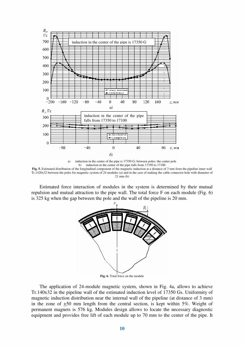
Calculated distribution of the longitudinal component of the magnetic induction at the
distance of 3 mm from the pipeline internal wall in the area between the module poles is
shown in Fig. 5.
As shown in Fig. 5a, magnetic flux loss, due to the gaps between the poles, appear
only at the distance of 100 ... 120 mm from each pole. In the area of flaw detector control
(+50 mm from the center of symmetry) the distribution of magnetic induction can be
considered uniform. There is a hole in the center of magnetic module for installation of
communication cable to connect sensors with the processing and storage unit.
The influence of the central hole in the magnetic core (Fig. 5b) is negative. That’s why
it is recommended to put the tube of soft magnetic material into the hole after
installation of the cable connector plug.
10
a) induction in the center of the pipe is 17350 G; between poles; the center pole
b) induction in the center of the pipe falls from 17350 to 17100
Fig. 5. Estimated distribution of the longitudinal component of the magnetic induction at a distance of 3 mm from the pipeline inner wall
Tr.1420x32 between the poles for magnetic system of 24 modules (a) and in the case of making the cable connector hole with diameter of
21 mm (b)
Estimated force interaction of modules in the system is determined by their mutual
repulsion and mutual attraction to the pipe wall. The total force F on each module (Fig. 6)
is 325 kg when the gap between the pole and the wall of the pipeline is 20 mm.
Fig. 6. Total force on the module
The application of 24-module magnetic system, shown in Fig. 4a, allows to achieve
Tr.14032 in the pipeline wall of the estimated induction level of 17350 Gs. Uniformity of
magnetic induction distribution near the internal wall of the pipeline (at distance of 3 mm)
in the zone of +50 mm length from the central section, is kept within 5%. Weight of
permanent magnets is 576 kg. Modules design allows to locate the necessary diagnostic
equipment and provides free lift of each module up to 70 mm to the center of the pipe. It
induction in the center of the pipe is 17350 G
induction in the center of the pipe
falls from 17350 to 17100

11
makes possible to use the developed magnetic modules in the magnetic system of flaw
detector of the pipe wall Tr.142032.
The influence of contacting elements on the internal flow coating (IC) was tested on special
stand. [5]
We checked the influence of contacting elements of cylindrical shape made of rubber
and conical shape elements made of polyurethane (d = 12 mm, h = 30 mm).
Preliminarily the coefficients of static friction f0 and sliding friction f, for dry friction
mode without abrasive, were determined by GOST 11629-75. It is stated that for
polyurethane f0=0.328, f=0.232; for rubber f0=0,679, f=0,519, ie polyurethane has 2 times
smaller friction coefficient as compared with the rubber. So it proves that the pair of
polyurethane I� has less wear.
When using rubber as contacting element for dry abrasive friction modes and friction
with wet abrasive in the speed range of 12 to 60 mm/s and the contact forces of 10 and 20
N (8...16 N/cm2), the identical types of IC wear depth dependencies from the system P, v
2,
are kept, where P is the contact force, and v is the IC wear rate.
IC wear by rubber most intensively occurs in wet friction mode with abrasive. When
parameter P = 10 N and v = 60 mm/s IC wear by rubber in the wet friction with abrasive is
about 5.9 times stronger than during dry friction with abrasive, but if P is 2 times more,
friction is 2.4 times more intense. Wet and dry frictions without abrasive do not cause wear
during IC contact with rubber or polyurethane.
The incubation period (time till IC wear by rubber) at P = 20 N and v = 60 mm/s is
approximately 1 sec, but in case with polyurethane - 100 hours, i.e. polyurethane is
significantly much better than rubber as the IC contacting element. In the presence of water
and sand, there is no sense to use rubber, as the contacting element, for pipeline cleaning,
due to intensive IC wear at low speed (less than 0.1 m /s).
3. Measures to protect flow coating
When designing the magnetizing systems two variants of introduction of magnetic field
in the pipe wall were considered:
1) metal magnetic brushes fitted with protective ceramic spherical tips. But the life time
of brushes with ceramic spherical tips was 600 ... 800 kilometers of pipe. At the same time
there was a high probability of tip tear away from the brush, which could damage the
internal flow coating. The life time of brushes should be at least 1500 km with minimum
probability of separation tips, so this variant was not accepted;
2) Contactless magnetizing system for the pipe wall (gap between the magnet face and
the pipe wall is 20 mm). To avoid contact between the face of the magnetic system and the
pipeline surface, the polyurethane plate of 20 mm thickness is put into the gap between the
wall and the end surface. Magnetic module is placed on the wheeled cart, at the same time
the gap between the polyurethane plate and the pipeline surface is 5 mm. This variant was
implemented for design of flaw detector;
3) Sliding friction was replaced by rolling friction to reduce the friction coefficient
between the pipeline surface and polyurethane sleeves. Wheel units with polyurethane tires
were inserted to these sleeves.
On the basis of the above mentioned requirements the corrosion flaw detector for
inspection of flow coating pipelines was developed (Fig. 7) [6 - 9].
Corrosion flaw detector was tested at proving ground. Proving ground has the test
section of the pipeline with internal coating, welded of tubes with diameter of 1420 mm
with wall thickness from 15.7 to 33.4 mm, including the central test tube with wall
thickness of 33.4 mm, manufactured by Izhorskiy Pipe Mill according to TU14- 3P-1430-
2007, with internal flow coating according to STO Gazprom 2-2.2-180-2007, and pipes
with diameter of 1420 mm without internal coating (Fig. 8).
12
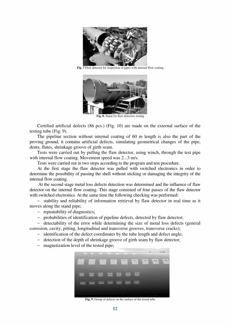
Fig. 7 Flaw detector for inspection of pipes with internal flow coating
Fig. 8. Stand for flaw detectors testing
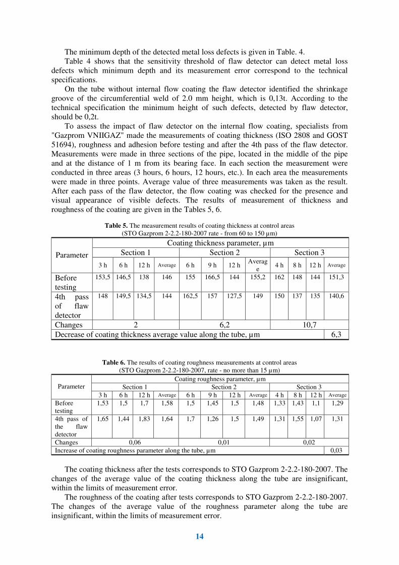
Certified artificial defects (86 pcs.) (Fig. 10) are made on the external surface of the
testing tube (Fig. 9).
The pipeline section without internal coating of 60 m length is also the part of the
proving ground, it contains artificial defects, simulating geometrical changes of the pipe,
dents, flutes, shrinkage groove of girth seam.
Tests were carried out by pulling the flaw detector, using winch, through the test pipe
with internal flow coating. Movement speed was 2...3 m/s.
Tests were carried out in two steps according to the program and test procedure.
At the first stage the flaw detector was pulled with switched electronics in order to
determine the possibility of passing the shell without sticking or damaging the integrity of the
internal flow coating.
At the second stage metal loss defects detection was determined and the influence of flaw
detector on the internal flow coating. This stage consisted of four passes of the flaw detector
with switched electronics. At the same time the following checking was performed:
− stability and reliability of information retrieval by flaw detector in real time as it
moves along the stand pipe;
− repeatability of diagnostics;
− probabilities of identification of pipeline defects, detected by flaw detector;
− detectability of the error while determining the size of metal loss defects (general
corrosion, cavity, pitting, longitudinal and transverse grooves, transverse cracks);
− identification of the defect coordinates by the tube length and defect angle;
− detection of the depth of shrinkage groove of girth seam by flaw detector;
− magnetization level of the tested pipe;
Fig. 9. Group of defects on the surface of the tested tube

13
Fig. 10. Characteristics of certified artificial defects
Table 4. Minimum depth of detected metal loss defects of pipe.
Error
Defect form
Value by
technical
specifications
Actual value
by defects
album, mm
Values
received
from test,
mm
From technical
specifications From test
General corrosion 0,05t (1,67 mm) 1,85 1,95 0,1t (3,34 mm) 0,003t (0,01 mm)
Cavity 0,1t (3,34 mm) 3,0 3,2 0,12t (4,01 mm) 0,006t (0,2 mm)
Pitting 0,2t (6,68 mm) 3,5 3,7 0,2t (6,68 mm) 0,006t (0,2 mm)
Longitudinal
groove
0,2t (6,68 mm) 3,45 3,55 0,2t (6,68 mm) 0,003t (0,1 mm)
Transverse groove 0,1t (3,34 mm) 3,5 3,7 0,12t (4,01 mm) 0,006t (0,2 mm)
Transverse cracks
(cut)
0,1t (3,34 mm) 3,1 3,3 0,1t (3,34 mm) 0,006t (0,2 mm)
− sufficiency of mounted density of sensors on the basis of a resolution of the flaw
detector;
− polling step of transducer system by fixing the number of entries of any selected
shell sensor at 1 meter of testing tube.
The report on the results of flaw detector run is made. The flaw detector found all of 86
defects during each run, it proves their complete detection, stability and reliability of
information retrieval.
The magnetization level of the pipe wall in the testing area, measured at each pass of
the flaw detector, is not less than 15 mT, which meets the requirements of technical
specification.
The density of sensors location (estimated on the basis of resolution), and polling step of
transducer system of flaw detector meet the technical specification requirements. The
evaluation of these parameters is given in the report.
Stand-pipe wall thickness t = 32mm
General requirements:
the distance between the edges of the defects along the longitudinal axis of the pipe, not less than 200mm
the distance between the edges of the defects across the longitudinal axis of the pipe, not less than 400mm
General corrosion: square defects, 100x100 mm and depth (mm) 1.6; 3.2; 4.8; 6.4; 9.6; 12.8; 16.0; 19.2 �
22.4
Cavity:
- round defects, diameter of 32 mm and depth (mm) 3.2; 6.4; 9.6; 12.8; 16.0; 19.2 � 22.4
- defects, length of 32 mm, width 16 mm and depth (mm) 3.2; 6.4; 9.6; 12.8; 16.0; 19.2 � 22.4
- defects, length of 16 mm, width 32 mm and depth (mm) 3.2; 6.4; 9.6; 12.8; 16.0; 19.2 � 22.4
Pitting: round defects, diameter 22.4 mm and depth (mm) 3.2; 6.4; 9.6; 12.8; 16.0; 19.2 � 22.4
Longitudinal groove:
- defects, length 64 mm, width 32 mm and depth (mm) 3.2; 6.4; 9.6; 12.8; 16.0; 19.2 � 22.4
- defects, length 96 mm, width 32 mm and depth (mm) 3.2; 6.4; 9.6; 12.8; 16.0; 19.2 � 22.4
Transverse groove:
- defects, length 32 mm, width 64 mm and depth (mm) 3.2; 6.4; 9.6; 12.8; 16.0; 19.2 � 22.4
- defects, length 32 mm, width 96 mm and depth (mm) 3.2; 6.4; 9.6; 12.8; 16.0; 19.2 � 22.4
Transverse cracks:
- transverse cut to the longitudinal axis of the tube, length 64 mm and depth (mm) 3.2; 6.4; 9.6; 12.8;
16.0; 19.2 � 22.4
- transverse cut to the longitudinal axis of the tube, length 96 mm and depth (mm) 3.2; 6.4; 9.6; 12.8;
16.0; 19.2 � 22.4
- transverse cut to the longitudinal axis of the tube, length 160 mm and depth (mm) 3.2; 6.4; 9.6; 12.8;
16.0; 19.2 � 22.4
14
The minimum depth of the detected metal loss defects is given in Table. 4.
Table 4 shows that the sensitivity threshold of flaw detector can detect metal loss
defects which minimum depth and its measurement error correspond to the technical
specifications.
On the tube without internal flow coating the flaw detector identified the shrinkage
groove of the circumferential weld of 2.0 mm height, which is 0,13t. According to the
technical specification the minimum height of such defects, detected by flaw detector,
should be 0,2t.
To assess the impact of flaw detector on the internal flow coating, specialists from
"Gazprom VNIIGAZ" made the measurements of coating thickness (ISO 2808 and GOST
51694), roughness and adhesion before testing and after the 4th pass of the flaw detector.
Measurements were made in three sections of the pipe, located in the middle of the pipe
and at the distance of 1 m from its bearing face. In each section the measurement were
conducted in three areas (3 hours, 6 hours, 12 hours, etc.). In each area the measurements
were made in three points. Average value of three measurements was taken as the result.
After each pass of the flaw detector, the flow coating was checked for the presence and
visual appearance of visible defects. The results of measurement of thickness and
roughness of the coating are given in the Tables 5, 6.
Table 5. The measurement results of coating thickness at control areas
(STO Gazprom 2-2.2-180-2007 rate - from 60 to 150 µm)
Coating thickness parameter, µm
Section 1 Section 2 Section 3 Parameter
3 h 6 h 12 h Average 6 h 9 h 12 h Averag
e 4 h 8 h 12 h Average
Before
testing
153,5 146,5 138 146 155 166,5 144 155,2 162 148 144 151,3
4th pass
of flaw
detector
148 149,5 134,5 144 162,5 157 127,5 149 150 137 135 140,6
Changes 2 6,2 10,7
Decrease of coating thickness average value along the tube, µm 6,3
Table 6. The results of coating roughness measurements at control areas
(STO Gazprom 2-2.2-180-2007, rate - no more than 15 µm)
Coating roughness parameter, µm
Section 1 Section 2 Section 3 Parameter
3 h 6 h 12 h Average 6 h 9 h 12 h Average 4 h 8 h 12 h Average
Before
testing
1,53 1,5 1,7 1,58 1,5 1,45 1,5 1,48 1,33 1,43 1,1 1,29
4th pass of
the flaw
detector
1,65 1,44 1,83 1,64 1,7 1,26 1,5 1,49 1,31 1,55 1,07 1,31
Changes 0,06 0,01 0,02
Increase of coating roughness parameter along the tube, µm 0,03
The coating thickness after the tests corresponds to STO Gazprom 2-2.2-180-2007. The
changes of the average value of the coating thickness along the tube are insignificant,
within the limits of measurement error.
The roughness of the coating after tests corresponds to STO Gazprom 2-2.2-180-2007.
The changes of the average value of the roughness parameter along the tube are
insignificant, within the limits of measurement error.

15
The coating adhesion, measured by lattice cuts, after four runs of flaw detector did not
change; it was 0 points according to ISO classification.
Visually apparent defects and damages were not detected on the surface of the inner
coating.
4. Advantages of the development
• design of highly efficient and reliable integrated system for in-line control. Tracking
systems of flaw detector, combined with the latest technology and components in
the development of the operation system, will allow to fulfill the inspection at the
new higher level;
• on-line information on the results of in-line control comes within 24 hours after the
inspection;
• high confirmability of the defects thanks to the system development and know-how
in the design of hardware and software;
• sustainable control of defects and anomalies in the longitudinal weld area;
• run of flaw detector along the tested pipe is controlled in real time by marker
devices;
• the accuracy in determination of the defect location, prompt data transmission about
flaw detector location due to the automated system of flaw detector tracking;
• implementation of the energy-saving power supply pulse system of flaw detector,
which reduces the battery capacity and increases the working time;
• design of universal data storage unit;
• pulse protection system for electronics is developed, which allows to arrange
maintenance once a year after 2000 km pipeline control without opening the
pressurized container.
The above mentioned characteristics show that the developed system can be relate to
the new generation of flaw detectors.
During scientific, research and development works on the design of flaw detector, the
marker device was developed to fix time when small magnetic pulses occur
(commensurable with magnetic field of the Earth), when flaw detector passes the marker
device during diagnostic work at gas pipelines. The data from marker devices is used to
find the pipe defects at site.
Summary 1. The main technical characteristics of flaw detector, obtained from the acceptance
test results on the stand, meet the requirements of technical specification.
2. According to test results, the committee confirmed that flaw detector had found all
of 86 artificial defects during each run. It proves the stability and reliability of data retrieval
by flaw detector.
3. Measurement accuracy of defect parameters, identified by flaw detector, meets the
requirements of technical specification.
4. The flaw detector can’t damage the internal flow coating of the pipe. The coating
parameters of thickness, roughness and adhesion remained the same before and after
testing.
16
References:
[1] Kliuev V. V. (Ed.), Muzhitskii V. F., Gorkunov E. S., Shcherbinin V. E. (2006). Non-
destructive testing. Handbook. In 8 volumes. Vol. 6. Book 1. Magnetic methods of testing.
(2nd (Revised and Supplemented) ed.). Moscow: Mashinostroenie.
[2] Bakunov A. S. (2011). Magnetic testing. Moscow: Izdatel'skii dom «Spektr».
[3] Kliuev V. V. (Ed.), Muzhitskiy V. F., Gorkunov E. S., Scherbinin V. E. (2010).
Nondestructive testing: handbook. In 8 volumes. Vol. 1. In 3 books. Moscow: Izdatel'skii
dom «Spektr».
[4] Sergeev K. L., Blagoveshchenskaia N. S., Utkin M. M. et al. (2009). Report on the
complex computational work to determine the optimal scheme of the magnetic system of
flaw detector for pipe wall and the magnetic system timer annular seam for the two sizes of
tubing of 1420×32 pipe and 1220×41 pipe. Moscow.
[5] Belozerov P. G., Kireev V. A., Pomakhaeva L. I. (1998). The test results of the in-pipe
polymeric coatings of the main gas pipelines. Moscow: VNIIGAZ.
[6] Kovalenko A. N. (2010). Theoretical and experimental studies of magnetic fields
defects of finite size and the creation of specialized scanners for inspection of pipelines.
PhD dissertation. Moscow: CJSC «NIIIN MNPO «SPEKTR».
[7] Kovalenko A. N. (2013). Analysis of factors affecting the reliability of the control lines
magnetic flaw. Kontrol'. Diagnostika, (8), pp. 30-37.
[8] Kovalenko A. N. (2014). Intratube magnetic particle inspection. Kontrol'. Diagnostika,
(3), pp. 84-88. doi: 10.14489/td.2014.03.pp.084-088.
[9]Kovalenko A. N., Artemyev I. B. Intratubel defectoscopy pipelines with smooth coating.
(2015). Kontrol'. Diagnostika, (4), pp. 41-52. doi: 10.14489/td.2015.04.pp.041-052