Internal architecture, geometry and reservoir ... · The Lower Cretaceous Scapa Sandstone Member...
12
Introduction 1 1 INTRODUCTION 1.1 Deep-water clastic systems as important exploration targets In the early 1990s, 25% of the known hydrocarbon reservoirs were located within deep-water clastic systems (Weimer & Link 1991). Turbidites as the volumetrically most significant deep-water deposits are the primary reservoir type within these plays. Since 1970 a three-fold increase in discovered turbidite reservoirs has been recorded. This trend is expected to rise considerably in the future (Pettingill 1998). Presently, turbidites are known to produce oil and/or gas in more than 80 basins world wide, totalling 1200 to 1300 oil and gas fields including discoveries and producing fields (Stow & Mayall 2000). It has been predicted that in the future 75% of the potential hydrocarbon reservoirs are to be found in deep-water clastic systems. Consequently, the global turbidite exploration is presently considered to be at an immature stage but will play a significant role in the future of hydrocarbon exploration and production (Pettingill 1998). Deep-water clastic systems, comprising submarine fan systems and related turbidite systems (Reading 1996), host large volumes of oil-in-place, but the recovery factor is low due to their complex reservoir architecture. A clear understanding of their geometry, facies relationships and reservoir quality is therefore critical for exploring and exploiting these deposits effectively (Tyler et al. 1984). Most studies have focused on channel-fill deposits which form well constrained, linear reservoir bodies with typically high porosities and permeabilities due to general better sorting, larger grain size, thicker beds and fewer interbedded shaley permeability barriers. An abundance of literature exists (e.g. Walker 1978, 1980; Bouma et al. 1985; Damuth et al. 1988; Clark & Pickering 1996; Pirmez et al. 1997). However, relatively little research has gone into the equally attractive exploration target of the non-channelized units which possess an important hydrocarbon reservoir potential because of their large areal extent (Schuppers 1995). These often comprise sheet-sands and are commonly termed lobe deposits. McLean (1981) demonstrated that particularly proximal lobe deposits with their high sand/shale ratios and likely higher porosities and permeabilities are of special interest. Turbidites in distal lobe position have also proven to be highly permeable (Hewlett & Jordan 1993). Studies focus especially on reservoir characterisation in terms of lithohydraulic units, where lithological and petrophysical entities form flow units. Due to the economic importance and the scientific challenge deep-water clastic systems pose, key research areas have been outlined at the beginning of the 21 st century in order to grasp their complexity (Stow & Mayall 2000). One focal point is to scrutinise these systems at the level of architectural building blocks including the quantification of their attributes. At a larger scale it is important to examine the fundamental controls which determine deep-water facies and architecture. 1.2 Aims of thesis A consortium of 5 oil companies (Amarada Hess, Amoco – now BP-Amoco, Conoco, Elf and Enterprise) sponsored this detailed, primarily field-based study (Cingöz Formation, S-Turkey) to analyse the internal architecture of non-channelized, sandy turbiditic deposits and the factors governing their evolution in the context of their particular fan setting. The application of field-derived concepts to a subsurface data set (Scapa Field, North Sea) is evaluated. This study was carried out as part of a larger research project of the deep water clastic research group at Aberdeen University, UK. The aims of the study were: • to identify different subenvironments within the sandy, primarily non-channelized fan deposits and define their basic building blocks (architectural elements) sensu Mutti & Normark (1987) and subenvironments (components) sensu Mutti (1977). • to unravel sandbody geometries and lithological continuity at different hierarchies of scale and quantify their physical attributes. • to identify vertical / lateral trends in the differentiated subenvironments (lobe types) as well as analyse the observed down-current trends.
Transcript of Internal architecture, geometry and reservoir ... · The Lower Cretaceous Scapa Sandstone Member...

Introduction
1
1 INTRODUCTION
1.1 Deep-water clastic systems as important exploration targets In the early 1990s, 25% of the known hydrocarbon reservoirs were located within deep-water clastic systems (Weimer & Link 1991). Turbidites as the volumetrically most significant deep-water deposits are the primary reservoir type within these plays. Since 1970 a three-fold increase in discovered turbidite reservoirs has been recorded. This trend is expected to rise considerably in the future (Pettingill 1998). Presently, turbidites are known to produce oil and/or gas in more than 80 basins world wide, totalling 1200 to 1300 oil and gas fields including discoveries and producing fields (Stow & Mayall 2000). It has been predicted that in the future 75% of the potential hydrocarbon reservoirs are to be found in deep-water clastic systems. Consequently, the global turbidite exploration is presently considered to be at an immature stage but will play a significant role in the future of hydrocarbon exploration and production (Pettingill 1998). Deep-water clastic systems, comprising submarine fan systems and related turbidite systems (Reading 1996), host large volumes of oil-in-place, but the recovery factor is low due to their complex reservoir architecture. A clear understanding of their geometry, facies relationships and reservoir quality is therefore critical for exploring and exploiting these deposits effectively (Tyler et al. 1984). Most studies have focused on channel-fill deposits which form well constrained, linear reservoir bodies with typically high porosities and permeabilities due to general better sorting, larger grain size, thicker beds and fewer interbedded shaley permeability barriers. An abundance of literature exists (e.g. Walker 1978, 1980; Bouma et al. 1985; Damuth et al. 1988; Clark & Pickering 1996; Pirmez et al. 1997). However, relatively little research has gone into the equally attractive exploration target of the non-channelized units which possess an important hydrocarbon reservoir potential because of their large areal extent (Schuppers 1995). These often comprise sheet-sands and are commonly termed lobe deposits. McLean (1981) demonstrated that particularly proximal lobe deposits with their high sand/shale ratios and likely higher porosities and permeabilities are of special interest. Turbidites in distal lobe position have also proven to be highly permeable (Hewlett & Jordan 1993). Studies focus especially on reservoir characterisation in terms of lithohydraulic units, where lithological and petrophysical entities form flow units. Due to the economic importance and the scientific challenge deep-water clastic systems pose, key research areas have been outlined at the beginning of the 21st century in order to grasp their complexity (Stow & Mayall 2000). One focal point is to scrutinise these systems at the level of architectural building blocks including the quantification of their attributes. At a larger scale it is important to examine the fundamental controls which determine deep-water facies and architecture.
1.2 Aims of thesis A consortium of 5 oil companies (Amarada Hess, Amoco – now BP-Amoco, Conoco, Elf and Enterprise) sponsored this detailed, primarily field-based study (Cingöz Formation, S-Turkey) to analyse the internal architecture of non-channelized, sandy turbiditic deposits and the factors governing their evolution in the context of their particular fan setting. The application of field-derived concepts to a subsurface data set (Scapa Field, North Sea) is evaluated. This study was carried out as part of a larger research project of the deep water clastic research group at Aberdeen University, UK. The aims of the study were:
• to identify different subenvironments within the sandy, primarily non-channelized fan deposits and define their basic building blocks (architectural elements) sensu Mutti & Normark (1987) and subenvironments (components) sensu Mutti (1977).
• to unravel sandbody geometries and lithological continuity at different hierarchies of scale and quantify their physical attributes.
• to identify vertical / lateral trends in the differentiated subenvironments (lobe types) as well as analyse the observed down-current trends.

Introduction
2
• to investigate heterogeneities at different scales for the identified elements (lobe types) and their implication in terms of hydrocarbon exploration.
• to re-evaluate the existing fan framework for the two study areas to place the observed deposits and field relationships into a more refined context.
• to analyse the stacking patterns and quantify the key controlling factors influencing lobe and fan development and discuss the constraints/limitations of models.
• to evaluate the application of field-derived concepts on a subsurface data set and address the problems which exist. The limitations and resulting implications are discussed.
Outcrop study: E-Fan, Cingöz Formation, Southern Turkey The Mid-Miocene Cingöz Formation (Adana Basin, southern Turkey) is a to date little studied example of a multi-sourced slope apron - basin floor fan deposited in a triple junction escape basin exhibiting typical foreland basin character during a time of gradually rising sea level (Gök�en et al. 1988; Ünlügenç et al. 1992; Gürbüz 1993; Gürbüz & Kelling 1993). Exposures of thick units of primarily non-channelized sheet-sands are relatively good and of large lateral extent, partly at interwell scale (up to 1.5 km). They permit detailed studies in key proximal and distal locations within the fan system. Additionally, the complex relationship of the submarine fan with the slope can be studied. Earlier research and this study permit the establishment of a relatively well known fan framework and thus the controlling factors of the lobe development can be studied in detail. Subsurface study: S10 interval, Scapa Field, North Sea. The Lower Cretaceous Scapa Sandstone Member (Scapa Field, North Sea) is an example of a slope-apron fan deposited in a half-graben system during rising sea level (Harker & Chermark 1992; Hendry 1994). The deposits of the Scapa System have been described to be mainly composed of channel-fill and subordinate lobe deposits (McAfee 1993). With the exception of Riley et al. (1992) who introduced the chronostratigraphic environmental reconstruction at a relatively broad scale for the Scapa Field, all published and unpublished reports use fluid-flow units (reservoir/non-reservoir units), which essentially are diachronous, as the basis of their evaluation. The recognition and characterisation of lobe deposits, based on core and well log data in conjunction with outcrop-derived concepts is tested on the largest oil-bearing unit within the system, the chronostratigraphic S10 interval.
1.3 State of the art: deep-water clastic systems - processes and facies models Until the beginning of this century, the sediments on the sea floor were thought to be solely composed of fine-grained biogenic oozes and pelagic muds (Friedman & Sanders 1997). When coarse clastic sediments were discovered in the deep sea, transport and depositional mechanisms became the object of investigation. It was shown that the deposits of gravity-controlled mass-transport processes (turbidites and debris flows) are the major components of deep-water clastic systems (e.g. Mutti 1992; Stow et al. 1996; Friedman & Sanders 1997). The first models classifying the processes, deposits and the anatomy of these observed systems emerged in the 1960’s and early 70’s (Reading 1996; historic review in: Shanmugam 2000). The establishment and evolution of depositional models has been very dynamic and occasionally confusing. At the end of the 20th century many of these models have been challenged, some, in fact, were abandoned. Common points of dispute are the validity of the turbidite paradigm, where turbidites are considered to make up the bulk of deep-water clastic systems. Shanmugam (2000), for example, has long disputed this suggesting that many turbidites are in fact sandy debris flow deposits. Distinct facies cyclicity, long considered to be diagnostic of fan environments and development, was shown to be questionable as Anderton (1995) demonstrated a predominance of random processes in fan deposition. Over the years, the looser usage of terms and definitions has clearly resulted in creating confusion (Miall 1999). Stow & Mayall (2000), Shanmugam (2000) and Miall (1999) present summaries and discussions of these topics.

Introduction
3
Deep-water processes and classification of deposits Gravity-driven processes are responsible for a range of deposits found in the deep sea. Slumps and debris flows tend to dominate more proximal and turbidites more distal settings. However, either type of deposit can occur at any location. It is generally accepted that turbidites are the most common deposits in deep-water clastic systems (Stow & Mayall 2000) After 50 years, the turbidite paradigm is still dominant and everything from a 1 cm thick silt-laminated mudstone to a 50 cm thick boulder-pebble-sand graded megabed has been called a turbidite (Stow & Mayall 2000). Kuenen & Migliorini (1950) suggested density currents as agents for transporting coarse sediment into the deep sea, leaving graded deposits behind. Bouma (1962) was the first to propose a vertical facies model for turbidites which is commonly referred to as the Bouma Sequence or ‘classic turbidite’. Turbidites are principally recognised by i) normal size grading, ii) sharp basal contacts, iii) gradational upper contacts, iv) Bouma divisions (Ta-Te; fig. 1.1; Bouma 1962; Middleton & Hampton 1973) and v) deep-water fossil assemblages. Because many of the deposits found in deep-water systems did not always fit that definition in terms of accommodating the variety of grain sizes and sedimentary features, the original definition of turbidites was expanded. Stow & Shanmugam (1980) added a more detailed division for the silt-mud facies to the original model (fig. 1.1) and Lowe (1982) expanded it for the coarse grained fraction (subdivisions R1– S3). He classified turbidity currents into two main types: low-density flows, producing the classic turbidites, and high-density flows, producing coarser grained turbidites. This division is based on grain-size populations, particle concentrations and sediment-support mechanisms. This concept is now widely accepted. Shanmugam (2000) disputes this and regards high-density turbidites as sandy debris flow deposits, a concept first introduced by Hampton (1975) and further developed by Shanmugam et al. (1995) and Shanmugam (1996, 1997, 2000). This interpretation has been met by scepticism (e.g. Hiscott et al. 1997; Bouma et al. 1997, Lowe 1997), however, there is no current consensus (Shanmugam et al. 1997; Shanmugam & Moiola 1997). The different genetic implication is of great importance to the petroleum industry in terms of predicting reservoir geometry (Slatt et al. 1997) since high-density turbidites are considered to show great lateral extent as opposed to sandy debris flows. Recently, Shanmugam (2000) has implied that sandy debris flows are also capable of depositing thick, sandy and areally extensive deposits.
Fig. 1.1: Vertical facies model of (1) coarse-grained turbidites (Lowe 1982), (2) classic turbidites (also known as Bouma Sequence) and (3) fine-grained turbidites (Stow & Shanmugam 1980). Correlation of the S3 division with the turbidites with the Ta division of the Bouma Sequence is after Lowe (1982). Correlation of various divisons between classic turbidites is after Pickering et al. (1989) (from Shanmugam 2000).

Introduction
4
Not many sediment beds in the deep-sea were found to exhibit simple normal grading as was originally defined for turbidites. Harms & Fahnestock (1965), for example, suggested massive sandstones to result from turbidity currents. Kneller’s (1995) time-space matrix for turbidity currents led to the expansion of the model (fig. 1.2) recognising normal grading, massive (i.e. no grading) and inverse grading for turbidites depending on the flow conditions (waning, steady or waxing). Apart from the common Bouma (1962) and Lowe (1982) classification systems for turbidites (fig. 1.1), several other facies schemes exist. Mutti & Ricci Lucchi (1972), for example, introduced a scheme where deposits are divided according to grain size (gravel to mud) forming seven facies associations (A-G), which are produced by a limited range of processes. They are considered to be diagnostic of specific depositional environments, though, Shanmugam & Moiola (1988) and Bouma et al. (1985) showed that this approach is too simplistic.
Their scheme was further developed by Stow (1985a) and Pickering et al. (1986) who produced a scheme with classes, groups and facies with organised and disorganised groups and new classes (chaotic units and hemipelagites, oozes, chalks and cherts). Ghibaudo (1992) uses a descriptive scheme using 13 facies and 22 subfacies which are distinguished mainly on the basis of sediment type, i.e. grain size and composition, while subfacies further describe internal structures. Deep-water clastic facies models In the 70’s, two approaches were developed i) ancient fan models based on outcrop studies (Mutti & Ricchi Lucci 1972) and ii) models based on the study of modern submarine fan systems (Normark 1970). Both approaches were combined to a simple, all-purpose fan model by Walker (1978), the extended suprafan model where the feeder channel, upper fan, mid-fan/suprafan lobe
and lower fan are characterised by distinct facies. This approach proved to be too simplistic and it was subsequently refined as more and more data from modern submarine fan systems became available (Miall 1999). Many parameters such as basin size and shape, source, duration of activity, sediments etc. which are unique to a system were now taken into account to accommodate the complexity and range of deep-water clastic systems (Reading & Richards 1994). The environmental classification of turbidite systems, including fans, ramps and slope aprons, is now relatively well established. Stow & Mayall (2000) present a summary of models (fig. 1.3) which are classified on the basis of (i) volume and grain size of available sediment, and (ii) the nature of the supply system (number of input points) based on work by Reading & Richards (1994) and Stow et al. (1996). Gradations between the individual models are common. However, the long-reigning single universal model encompassing all aspects of deep-water clastic systems has been abandoned (Normark 1991; Walker 1992; Miall 1999). Architectural elements, hierarchies and geometries Because many models of deep-water clastic systems proved to be too broad to place observed subenvironments into context, attempts were made to break systems down into their fundamental building blocks, or architectural elements (Miall 1999). The concept of elements as the main building blocks which is equally applicable to modern and ancient submarine fan systems was put forward by Mutti & Normark (1987). They introduced five unique elements characterised by a suite of sedimentological features: (i) channel deposits, (ii) scours, ranging in size from large slope scours to macro-scale ones, (iii) lobes, which are defined as non-channelized sandstone deposits, (iv) channel-lobe transition zone, which contains features of both the channel and the lobe environment and (v) overbank deposits which are in lateral associations with the channel environment. Other approaches

Introduction
5
which are based on Miall’s (1985) classification scheme were developed (Pickering et al. 1995). Here, an architectural element is defined as a lithosome characterised by its geometry, facies composition, and scale representing a particular process or suite of processes occurring within a depositional system. The architectural geometries are independent of scale and facies. Stow & Mayall (2000) summarise the presently recognised architectural elements (fig. 1.4):
• hiatuses, erosional plains and other bounding surfaces • erosional slide and slump scours. • canyons, troughs, channels and gullies. • channel levees and overbank deposits. • depositional lobes (isolated, clustered, splay). • irregular mounds (slide, slump and debrite masses). • contourite drifts (elongate mounded, irregular patch, contourite-fan). • sheets and drapes on slopes, basins, fans and drifts. • megaturbidites and other megabeds • tectonic features (growth faults, diapirs, compressional fault mounds).
Each element may occur at a range of scales and within a hierarchy of similar features. The sedimentary composition, including facies associations and vertical sequences, that make up any one element, can vary, typically within a limited range. This “element” approach has initially caused confusion since the scale (from turbidite bed to turbidite complex (basin-fill scale), features (map-type or packets of beds) and stacking pattern have been used loosely by different systems. However, Stow & Mayall (2000) believe that for both outcrop studies and reservoir characterisation the “element” approach is an important one to follow, being ever mindful of the scale and stacking pattern of individual elements.
1.3.1 Lobe deposits
The term ‘lobe’ covers a wide spectrum of depositional facies associated with submarine fans. It originates from the lobate bulge first identified from modern submarine fan systems (Normark 1970). In outcrop this large-scale geometry is not readily recognised, often only inferred to be lobate, and Mutti & Ghibaudo (1972) and Mutti & Ricci Lucchi (1972) and Mutti & Normark (1987, 1991) presented field criteria to recognise them. These criteria are primarily based on vertical bed stacking patterns and facies associations. In the subsurface, lobe deposits have frequently been recognised (Mitchum 1985;Hewlett & Jordan 1993; Mitchum et al. 1993). Their planform geometry is readily distinguished on seismic data, but core information calibrated with interpretations of wireline logs are commonly used to interpret the depositional environment (Bryant & Flint 1993). Here, the recognition of bed boundaries plays an important role (e.g. Pickering et al. 1995; Reading 1996; Hurst et al. 1999). Not only is it difficult to tackle the problem of identifying ‘lobes’ in ancient and modern systems as well as recognising them in the subsurface, but inadequacies with respect to the existing terminology and criteria for submarine fan lobes, their implications for different lobe models and the resulting reservoir geometry exist. Shanmugan & Moiola (1991) discuss the common ‘lobe’ terminology (fig. 1.5):
a) The braided suprafan lobe is composed of stacked channel sand bodies with good lateral and vertical communication forming excellent reservoir facies.
b) Fanlobes, which refer to meandering channels and associated levee facies of large mud-rich submarine fans (e.g. Mississippi Fan), are characterised by offset stacked sand bodies with poor lateral and vertical communication.
c) Ponded lobes are representing mud-rich slump facies of slope environments, comprising generally poor reservoir facies because of their low sand content and poor sand-body connectivity.

Introduction
6

Introduction
7
Fig. 1.4: The principle architectural elements in deep-water systems (from Stow & Mayall 2000).

Introduction
8
d. The term depositional lobe sensu Mutti & Normark (1987, 1991) is applied to the non-channelized, laterally extensive sheet-like sandbodies observed in the field with good lateral and moderate vertical communication. They were first described from the Miocene Bobbio Formation / Italy by Mutti & Ghibaudo (1972). They are typically located in the outer fan environment sensu Mutti & Ricci Lucchi (1972).
The main characteristics of ancient depositional sandstone lobes are:
• packages bounded by even, parallel surfaces of thick, relatively coarse-grained sandstones, commonly 3-15 m thick.
• isolated bodies within mudstone sequences of few kms to several 10s of kms basinward extend.
• basin-wide features exhibiting abrupt onlap terminations with the slope facies and forming convex-upward bodies wedging gradually into thinner-bedded lobe-fringe deposits.
• exhibit grading (Bouma sequence) and vertical development of internal structures.
• show superposed, small-scale thickening-upward sequence, composed of a limited number of beds (<10; = compensation cycles).
• commonly display planar scours, chaotic impact features and rip-up clasts. • They represent the maximum reach of sand transported into basin.
Ultimately, the size and appearance of lobe deposits are recognised to be a function of the size of the system, the basin size and its configuration and the volume of individual turbidity currents. Lobe deposits can therefore have very different dimensions and shapes (Mutti & Normark 1987, 1991; Normark et al. 1993) with the underlying topography having a major effect on their development (Schuppers 1995). Outcrop and subsurface studies illustrated the difficulties of applying the term ‘lobe’. In practice there may be a tendency to infer the presence of lobes when one lacks evidence for channels.
Figure 1.5: Conceptual models showing 3D sand-body geometry of (A) suprafan lobes (e.g. Upper Miocene Capistrano Formation, California), (B) fanlobes (e.g.modern Mississippi fan, Gulf of Mexico), (C) ponded lobes (e.g. modern Ebro fan, Mediterranean), and (D) depositional lobes (e.g. Eocene Hecho turbidite system, Spain) with their generalized reservoir properties. Turbidite facies nomenclature after Mutti & Ricci Lucchi (1972), sand content information from cited examples (from Shanmugam & Moiola 1991).

Introduction
9
1.4 Field areas, database and methods
1) Outcrop study: E-Fan, Cingöz Formation Field area and database The field area, approximately 400 km2, comprises the eastern fan (E-Fan) of the Cingöz Formation. It is located about 50 km north of Adana, S-Turkey (fig. 1.6). The area is relatively densely wooded with the best outcrops occurring mostly along road cuts, locally deforested areas and rivers. Rare long lateral sections of several kilometres in length are exposed along hill sides. The beds generally dip gently southwards (10-20°) and show hardly any tectonic deformation. The outcrop quality is strongly affected by deep weathering, differential cementation and pervasive coating by lichens. The submarine fan systems of the Cingöz Formation have not been studied in detail in terms of modern sedimentological approaches. First attempts were made by Gürbüz (1993) and Gürbüz & Kelling (1993), who concentrated on the general fan development, facies associations and provenance studies. This study utilised their work as a broad basis for a detailed sedimentological analysis, however, major amendments to the previous interpretations proved to be necessary (Kostrewa et al. 1997; Satur 1999; Satur et al. 1997, 2000). Topographic maps at the scale of 1:25000 were used for facies mapping and orientation in the field (Adana – Sheets N34 – b1 & b2, {subordinately: ‘b3’ & ‘b4’}, Series K816, Edition 2THGK, 199). a) Facies mapping Facies mapping was carried out in order to establish fan/slope and channelized/non-channelized facies relationships. The mapped units are differentiated into channelized and non-channelized fan sediments, large-scale debris flow units, slope and carbonate platform deposits. Mapped units correspond to those differentiated by Gürbüz (1993) and Satur et al. (1997), the latter having carried out the bulk of the mapping in the NW area of the E-Fan, comprising the channelized unit.
b) Logging Three N-S cross-sections were logged initially at a scale of 1:100, concentrating on the primarily non-channelized sandy deposits to provide an overview and refine the previous fan-framework in order to tie in the detailed key study areas. Information from the channelized units was used from Satur et al. (1997) and
Introduction
10
for the more distal, less sandy and less well exposed sections of the fan system from Gürbüz (1993). The Bouma (1962) and Lowe (1982) classification systems were largely applied. The key study sections were chosen based on a) exposure, b) accessibility and c) location within the fan system. Six main study areas were defined: three fairly well-exposed primarily non-channelized sandy sections of relatively large extent (fig. 1.6; no. 1-3), two sections studying the fan-slope contact (fig. 1.6; no. 4-5) and one analysing the transition between the channel-fill and non-channelized deposits (fig. 1.6; no. 6). Logs were initially recorded at scales 1:10 and 1:20 with even the smallest sedimentological structures observed included. c) Lateral logging The technique of lateral logging is tested to qualify and quantify small-scale sedimentological variations within individual sandstone beds and packages of sandstones in the distal lobe environment where the outcrop quality is relatively good (fig. 1.6; no. 3). Three sections were selected, their length varying between 10 to 45 m. The following procedure was carried out:
A) selection of sandstone beds based on sufficient lateral extent and accessibility in already identified depositional sub-environments.
B) superimposition of a horizontal grid (1m spacing) and data recording to a resolution of 0.5 cm.
C) recorded data: bed thickness, grain size, internal structures (stratification), dish structures, shale clasts (type, amount), bioturbation (horizontal, vertical, infill), amalgamation planes (length, type, with / without clay drape), sole marks (type, amount) and scours (width, depth, infill).
D) calculated data: net:gross ratio, % sand, % shale. E) quantification of data within grid spaces are represented by histograms and/or
distribution curves in order to obtain information of lateral net:gross variability.
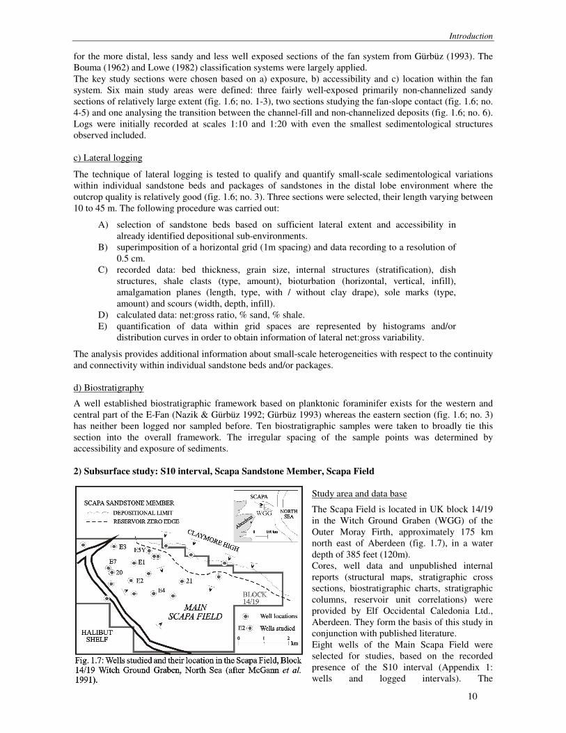
The analysis provides additional information about small-scale heterogeneities with respect to the continuity and connectivity within individual sandstone beds and/or packages. d) Biostratigraphy A well established biostratigraphic framework based on planktonic foraminifer exists for the western and central part of the E-Fan (Nazik & Gürbüz 1992; Gürbüz 1993) whereas the eastern section (fig. 1.6; no. 3) has neither been logged nor sampled before. Ten biostratigraphic samples were taken to broadly tie this section into the overall framework. The irregular spacing of the sample points was determined by accessibility and exposure of sediments. 2) Subsurface study: S10 interval, Scapa Sandstone Member, Scapa Field
Study area and data base The Scapa Field is located in UK block 14/19 in the Witch Ground Graben (WGG) of the Outer Moray Firth, approximately 175 km north east of Aberdeen (fig. 1.7), in a water depth of 385 feet (120m). Cores, well data and unpublished internal reports (structural maps, stratigraphic cross sections, biostratigraphic charts, stratigraphic columns, reservoir unit correlations) were provided by Elf Occidental Caledonia Ltd., Aberdeen. They form the basis of this study in conjunction with published literature. Eight wells of the Main Scapa Field were selected for studies, based on the recorded presence of the S10 interval (Appendix 1: wells and logged intervals). The

Introduction
11
biostratigraphic subdivision of the Scapa Sandstone Member (SSM) is based on dinocyst taxa (well reports; Riley et al. 1992). Two wells (E3, E4) comprise undifferentiated S10 subzones, while wells E2 and E7 are known to contain the S10 inerval but no biostratigraphic differentiation. For the overall analysis of the depositional model, the S10 interval with its subdivisions were utilised. Core Logging Cores were logged at an initial scale of 1:20 and a total of 785 feet (238 m) true stratigraphic thicknesses (TST) of the S10 interval were logged, as well as 250 feet (76 m) of undifferentiated Scapa Sandstone Member which are presumed to be part of the S10 interval. In none of the wells, the complete S10 interval was cored. Small scale structures and very thin beds were retained in the smaller scale and may therefore appear exaggerated (enclosure 1). All wells are deviated from the vertical by varying degrees. Core logging was carried out in drillers’ depth (feet) and conformed to log depth (feet) for the overall representation of the wells. Thicknesses have been calculated according to conversion factors provided by Elf Enterprise Caledonia Ltc. and given in metric TST throughout the text. a) Lithofacies and facies associations It became necessary to establish a refined lithofacies scheme to incorporate all the observed lithologies and sedimentary structures. The scheme generated 6 different lithofacies groups with 20 subtypes. Elf Occidental’s internal reports provided additional information on the petrography, diagenesis and poro-perm characteristics of the studied rocks. Lithofacies distribution patterns were established, analysed and facies associations determined. b) Wireline data Wireline data were provided by Elf Occidental at a scale of 1:40 and 1:200. Log readings of calliper (CL), gamma-ray (GR), sonic log (SL), resistivity log (RT), density (DL) and neutron log (NL), presented on logging depth and true vertical thickness (TVT) depth scale, were utilised (see Rider 1996) for detailed description of the application of wireline logs). In this study, the wireline log information was used for:
a) characterisation of the differentiated lithofacies. b) obtaining approximate lithologies and trends from gaps in the lithology logs which are
due to missing core sections (10 to 350 cm thick gaps) calibrated with information obtained from a) and to broadly identify lithologies from uncored parts of the S10 interval.
c) electrosequential analysis sensu Rider (1996) for the identification of distinctive trends within the S10 interval in conjunction with identified lithofacies sequences for interwell comparison.
d) Statistical analysis A variety of statistical methods were used to determine trends within the sandy successions. Since long strings of data are required for consequential analysis, only 4 wells were tested: E1, E2, E5Y and E7.
• Facies relationship diagrams (Selley 1969; Reading 1996), a visual appraisal of data to test sequential or non-sequential facies relationships in order to determine the most common facies transitions.
For the above methods, lithofacies groups (n = 6) rather than types (n = 20) were used to get meaningful, predicative trends.
• Bed thickness analysis by RUNS analysis (Davis 1986; Murray et al. 1996) where asymmetric bed thickness trends can be tested for: a) RAM: ‘runs about median’ (record ‘1’ for bed thicker than median, ‘0’ for thinner
than median) used for sequence grouping of thick or thin beds b) RUD: ‘runs up and runs down’ (an observation exceeds or is smaller than the
preceding observation) i) compare bed with preceding one (1 = thicker; 0 = thinner)

Introduction
12
ii) compare averaged thickness of next two succeeding beds with preceding one (1 = thicker; 0 = thinner) [two bed moving average after Heller & Dickinson (1985)] used for the identification of upward thickening and upward thinning bed cycles
Both RAM and RUD calculations were carried out. Davis (1986), Reading (1996), Murray et al. (1996) and Chen & Hiscott (1999a) discuss the common pitfalls in the application of statistical analysis and this study is sensitive to their comments when interpreting the results
2 CHARACTERISATION OF LOBE DEPOSITS IN OUTCROP: E-FAN, CINGÖZ FORMATION, S-TURKEY
2.1 Geological background
2.1.1 Location and setting The Miocene Cingöz Formation forms part of the thick Tertiary infill of the southern Turkish Adana Basin in a tectonically complex collisional setting. The basin is bound by the Ecemi� Fault Zone in the west, the Misis Structural High in the southeast and the overthrust Tauride Orogenic Belt in the north (Williams et al. 1995; fig. 2.1). The basin forms the northern part of the greater Çukurova Basin, separated from its southern part, the Iskenderum Basin, by the NE-SW trending Misis Structural High (Kelling et al. 1987). The Çukurova Basin extends submarine to Cyprus as the Cilicia-Adana Basin (Williams et al. 1995). The Çukurova Basin is located entirely on the Anatolian Plate (Williams et al. 1995) above the zone of Cenozoic suturing between the Afro-Arabian and the Euro-Asian plates (Sengör & Yilmaz 1981; Dewey et al. 1986). The age of the plate collision is not established, various authors assigning different ages to it: Late Cenozoic (Kelling et al. 1987), Early Miocene (Jackson & McKenzie 1984), Middle Miocene (Sengör 1979) and has most recently suggested to be of Eocene to Miocene age (Hempton 1982; Yilmaz 1993).
The structural evolution of SE Turkey is controlled by the interaction of several major wrench faults in the Kahraman Mara� triple junction (fig. 2.1), the N-S trending Dead Sea fault zone (Africa-Arabia), the NE-SW trending Bitlis Suture (Arabia-Eurasia) and the eastern part of the Hellenic Trench (Africa subducted under Eurasia) (Williams et al. 1995). The Adana Basin is thought to have formed as a result of the incompatibility problems arising at this triple junction (Hempton 1982; Robertson 1998). Gökçen et al. (1988) suggest that the basin originated as a perisutural foreland basin which subsequently developed into a transpressional basin