Intern report - IMC
39
Summer Internship Report (May-June 2013) Prepared by: Kartik Sharma Underg raduate Mining Engineering Student IIT_(BHU), Varanasi Under the guidance of: Mr. Pankaj Sinhha Director IMC-SRG Consulting (P) Limited 135, Jodhpur Park, Kolkata – 700068. India
-
Upload
kartik-sharma -
Category
Documents
-
view
220 -
download
0
Transcript of Intern report - IMC

Summer Internship Report
(May-June 2013)
Prepared by:
Kartik Sharma Undergraduate Mining Engineering Student
IIT_(BHU), Varanasi
Under the guidance of:
Mr. Pankaj Sinhha
Director
IMC-SRG Consulting (P) Limited
135, Jodhpur Park, Kolkata – 700068. India

Acknowledgement
I take this opportunity to express my profound gratitude and deep regards to Mr. Mihir (Senior Consultant, IMC- SRG) and Mr. R. Karthikeyan (Principal Consultant, IMC-SRG) for their exemplary guidance, monitoring and constant encouragement throughout the course of this internship. The blessing, help and guidance given by them time to time shall carry me a long way in the journey of life on which I am about to embark.
I also take this opportunity to express a deep sense of gratitude to
Mr. T. N. Gunaseelan (Managing Director, IMC-SRG) and Mr. Pankaj Kr Sinha (Director, IMC-SRG) for providing me this excellent opportunity of Internship. Their cordial support and valuable guidance has helped me in completing this task through various stages. Their encouragement to me during weekly presentations has really helped me in my improvement.
I am obliged to the family of IMC-SRG, namely Mr. D.K.Lamba, Mr.
Madan Pal Singh, Mr. K.K.Chaudhuri, Mr. S.N.Munsi, Mr. S.K.Pal, Mr. Ajay Singh, Mr. Rohit Dewangan, Mr. Prashant Tiwari, Ms Sharmila Patra, Ms Arpita Basak, Mr. Amitava Maji, Mr. Arbind Patel, Mr. Mihir Chandra,Mr. Somnath Gain,Ms Debasmita Mukherjee,Mr. Halder and many more, for the valuable information provided by them in their respective fields. I am grateful for their cooperation during the period of my internship.
Lastly, I thank almighty, my parents, brothers, sisters and friends for their constant encouragement without which this internship would not be possible.
Date: 29/06/2013
Place: Kolkata, India Kartik Sharma
Introduction
For summer internship at IMC-SRG Consulting (P) Limited, there were lot of applicants. Luckily I got this excellent opportunity of working in such a good consulting firm of Mining in India.
Summer Internship started on 8th of May, 2013, with a small interview with Mr. T. N. Gunaseelan (Managing Director, IMC-SRG), Mr. Pankaj Kumar Sinha (Director, IMC-SRG) and Mr. A. R. Ganapathy (Principal Consultant, IMC-SRG). It was mainly focussed on myself, my specific field of interest in Mining Engineering, so that I shall be involved in some live projects of the company. As I had a working experience of a project in field of Rock Mechanics (B.Tech. Project), so it was decided that I shall be working in the same field, namely Geotechnical Engineering.
So I was assigned to carry out Geotechnical analysis of a Mining project of Gujarat Fluorochemicals Ltd, to be carried out in Morocco. It is a Fluorite mining project, whose planning is being carried out by the team of IMC-SRG. Firstly it was planned to extract the fluorite deposit by methods of Underground mining. So I was asked to propose an underground roof support system, by going through all the geotechnical parameters. With a very great guidance of Mr. Tushar sir, an underground mining expert, I started this job, in which I made and followed a scheme of doing the geotechnical analysis, which I will elaborate in next section.
Meanwhile, I learnt some software widely used in Mine planning like AutoCAD Map 3D, Gemcom Surpac. In AutoCAD Map 3D, I started with the basics and with a proper direction from Mr. Rohit sir and Mr. Tushar sir, I designed the pit for some project. In Surpac also, I designed a 3D solid model of the Pit for GFL project. Mr. Prashant sir helped me learn the solid ore body modelling in Surpac.
After a while, the planning team of GFL project decided that the method of mining of the fluorite deposit shall be Open-pit, and after a time period of around 6-7 years the mining will be done by Underground methods. Hence my work then also got switched. Instead of going for an underground support design, now it included analysing the slopes of the open-pit for stability. Hence with a kind guidance of Mr. Karthikeyan sir, I

started this job, studying various parameters effecting the stability, and then I was supposed to work on some numerical modelling software (like FLAC, SLIDE). But due to lack of time it was not completed well. Still last section of this report includes analysis of slopes in an open-pit mine.I will do that analysis after joining my institute, as a future scope of work.
Last but not the least, I also learnt a lot while assisting my guides in their works. Some of them includes making a database of geotechnical reports of some mines, collecting details of mining equipment for the GFL project, translation of some Korean reports for an upcoming project.

Section 1:
Geotechnical Analysis (Project: GFL, Morocco)
Gujarat Fluorochemicals Ltd (“GFL”) Noida, India is part of a diversified group of companies and has been exploring opportunities globally for investment in mineral properties in general and Fluorspar deposits in particular. GFL identified Jbel Terrimi Fluorspar deposit in Morocco and initiated discussion on investment opportunities.
GFL engaged IMC-SRG Consulting (P) Ltd for Geological Study and Conceptual Mine Planning of Jbel Tirremi Fluorspar Deposit in Morocco.
As per the discussion with GFL, IMC-SRG started investigation and exploration of the fluorite deposit in Morocco, by taking data from previously drilled holes as well as by drilling around 10 new boreholes. All information related to the deposit like amount of reserve, strike, dip, geological conditions, hydrology etc. were collected and calculated. A conceptual mine planning was being carried out by IMC-SRG team based on the collected data.
As the decision of the team was to carry out underground method of mining for the deposit, it was a must to carry out the geotechnical analysis of the deposit and country rock. This task was being taken care by Mr. David Carter (DMT, Germany office). I was asked to make a proper stage wise plan for doing geotechnical study.
For doing the geotechnical analysis, site investigation is the first step to proceed with. Five processes are to be done in this, steps are as follows:-
1. Desktop Study: Geological setting, existing data, site history, aerial photographs and terrain assessment.
2. Definition of needs: Justify investigation requirements and anticipated cost.
3. Preliminary investigation: Depth, thickness and composition of strata.
4. Detailed site investigation: Quantitative characterisation of critical or founding strata.
5. Monitoring/Investigation: Instrumentation as required.
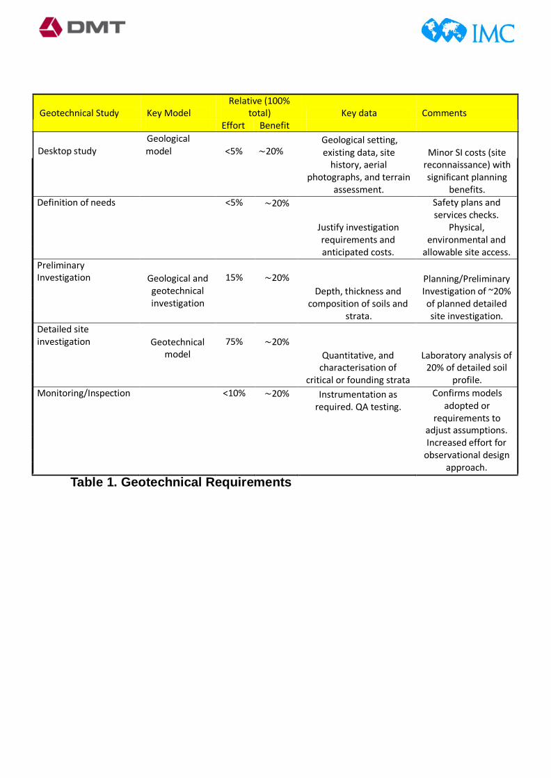
Geotechnical Study Key Model
Geological
Relative (100% total) Key data Comments
Effort Benefit Geological setting,
Desktop study model <5% ∼20% existing data, site Minor SI costs (site history, aerial
photographs, and terrain assessment.
reconnaissance) with significant planning
benefits. Definition of needs <5% ∼20% Safety plans and
services checks. Justify investigation Physical, requirements and environmental and anticipated costs. allowable site access. Preliminary Investigation Geological and 15% ∼20% Planning/Preliminary
geotechnical Depth, thickness and Investigation of ~20% investigation composition of soils and of planned detailed strata. site investigation. Detailed site investigation Geotechnical 75% ∼20%
model Quantitative, and Laboratory analysis of characterisation of 20% of detailed soil critical or founding strata profile. Monitoring/Inspection <10% ∼20%
Instrumentation as
required. QA testing. Confirms models
adopted or requirements to
adjust assumptions. Increased effort for observational design approach.
Table 1. Geotechnical Requirements
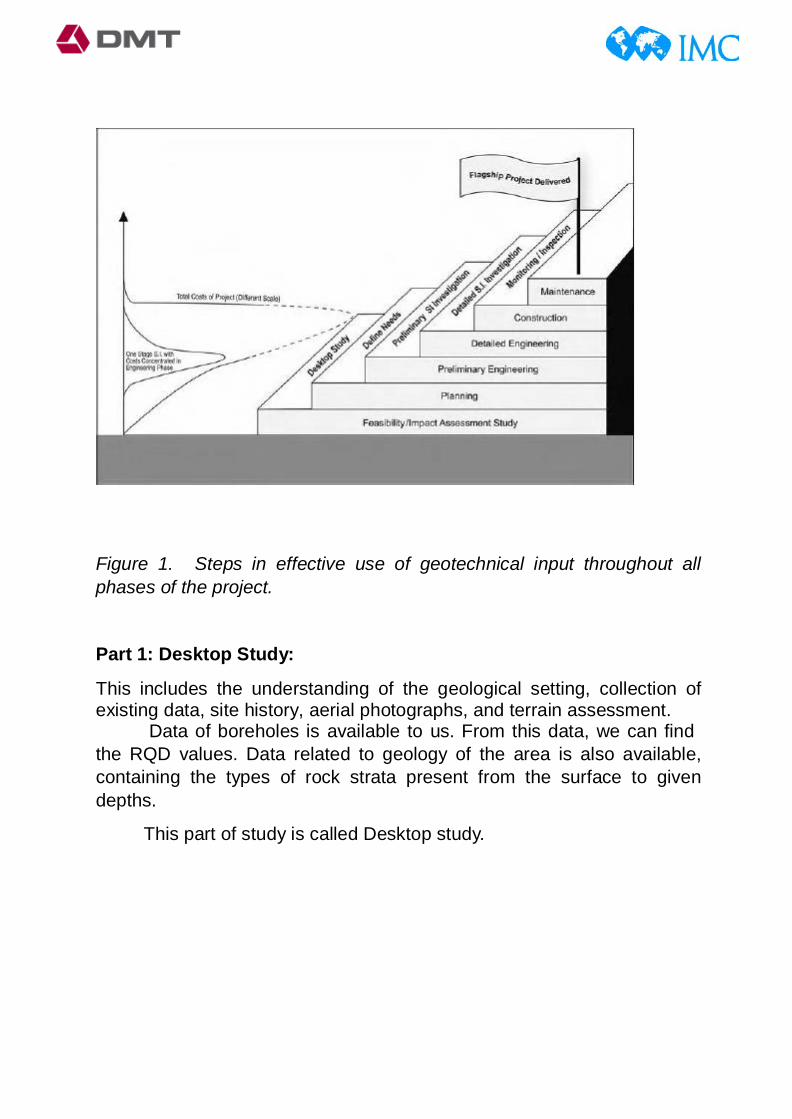
Figure 1. Steps in effective use of geotechnical input throughout all phases of the project.
Part 1: Desktop Study:
This includes the understanding of the geological setting, collection of existing data, site history, aerial photographs, and terrain assessment.
Data of boreholes is available to us. From this data, we can find the RQD values. Data related to geology of the area is also available, containing the types of rock strata present from the surface to given depths.
This part of study is called Desktop study.

Part 2: Definition of Needs:
This part consist of defining our aim. Our aim is mining the deposit by forming stopes, and then extracting them. For this purpose, we have to ensure that the surrounding rock must be stable during stoping. For this we go for geotechnical study rock mass.
For doing the geotechnical analysis of rock to conclude for its stability, we must have the following rock properties:
1. The rock joint pattern 2. The nature of the joints and the infilling material 3. The status of water seepage in the rock 4. The compressive & tensile strength of the rocks 5. The amount of explosives to be used in blasting and their
frequency
If we get these rock properties, then we can appoint a Rock Mass classification scheme, to decide the stability of rock and then we can go for employing a particular type of support system.
There are many rock mass classification systems, but most widely used and accepted system was given by Bieniawski, 1989 (modified version of previous). This is called Rock Mass Rating (RMR) system. It gives a rating to the rock on a 100 point scale, based on its following properties:
1. Uniaxial compressive strength of rock material. 2. Rock Quality Designation (RQD). 3. Spacing of discontinuities. 4. Condition of discontinuities. 5. Groundwater conditions. 6. Orientation of discontinuities.
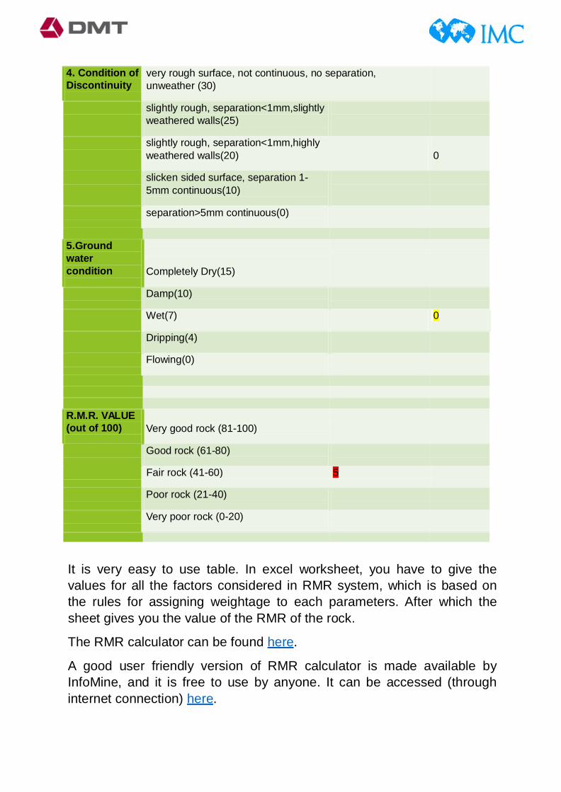
The RMR for different stopes is to be calculated separately (by calculating all factors listed for that part of ore body). Following table shows the RMR classification calculation scheme based on the above six parameters:
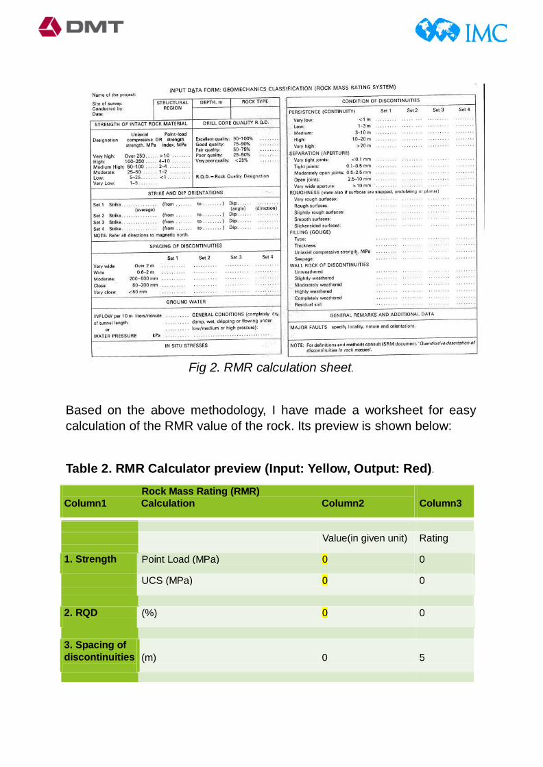
Fig 2. RMR calculation sheet.
Based on the above methodology, I have made a worksheet for easy calculation of the RMR value of the rock. Its preview is shown below:
Table 2. RMR Calculator preview (Input: Yellow, Output: Red).
Rock Mass Rating (RMR) Column1 Calculation Column2
Column3
Value(in given unit) Rating
1. Strength Point Load (MPa) 0 0
UCS (MPa) 0 0
2. RQD (%) 0 0
3. Spacing of discontinuities
(m) 0
5
4. Condition of Discontinuity
very rough surface, not continuous, no separation, unweather (30)
slightly rough, separation<1mm,slightly weathered walls(25)
slightly rough, separation<1mm,highly weathered walls(20)
0
slicken sided surface, separation 1- 5mm continuous(10)
separation>5mm continuous(0)
5.Ground water condition
Completely Dry(15)
Damp(10)
Wet(7) 0
Dripping(4)
Flowing(0)
R.M.R. VALUE (out of 100)
Very good rock (81-100)
Good rock (61-80)
Fair rock (41-60) 5
Poor rock (21-40)
Very poor rock (0-20)
It is very easy to use table. In excel worksheet, you have to give the values for all the factors considered in RMR system, which is based on the rules for assigning weightage to each parameters. After which the sheet gives you the value of the RMR of the rock.
The RMR calculator can be found here.
A good user friendly version of RMR calculator is made available by InfoMine, and it is free to use by anyone. It can be accessed (through internet connection) here.
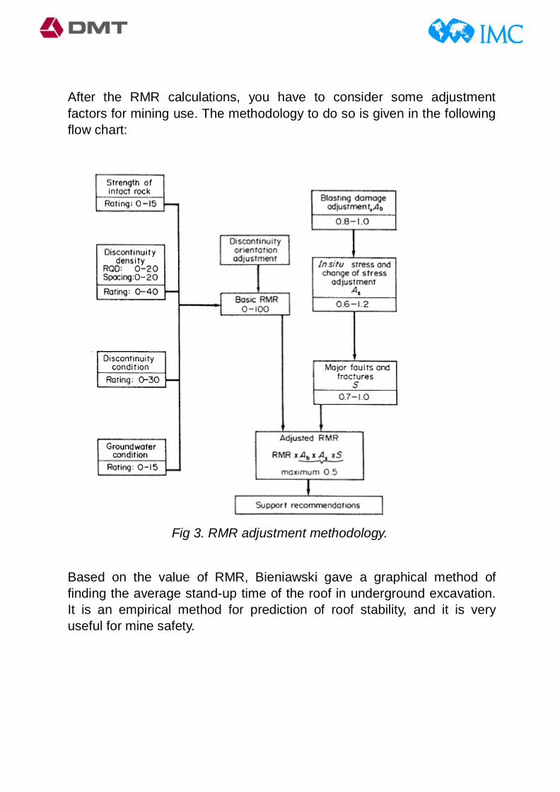
After the RMR calculations, you have to consider some adjustment factors for mining use. The methodology to do so is given in the following flow chart:
Fig 3. RMR adjustment methodology.
Based on the value of RMR, Bieniawski gave a graphical method of finding the average stand-up time of the roof in underground excavation. It is an empirical method for prediction of roof stability, and it is very useful for mine safety.

Fig 4. Average stand-up time prediction (interpretation from RMR value and roof span).

Section 2:
Working in AutoCAD Map 3D 2011
AutoCADis a software application for computer-aided design (CAD) and drafting. The software supports both 2D and 3D formats. The software is developed and sold by Autodesk, Inc., first released in December 1982 by Autodesk in the year following the purchase of the first form of the software by Autodesk founder John Walker. AutoCAD is Autodesk's flagship product and by March 1986 had become the most ubiquitous microcomputer design program in the world, utilizing functions such as "polylines" and "curve fitting". Prior to the introduction of AutoCAD, most other CAD programs ran on mainframe computers or minicomputers, with each CAD operator (user) working at a graphical terminal or workstation.
According to Autodesk company information, the AutoCAD software is now used in a range of industries, employed by architects, project managers and engineers, amongst other professions, and as of 1994 there had been 750 training centres established across the world to educate users about the company's primary products.
AutoCAD is used widely in all different type of industries. Each field has its own designing purpose, due to which Autodesk has release many types of AutoCAD versions. In mining and geological modelling purpose, we use MAP 3D version of AutoCAD. Following image shows how AutoCAD Map looks like.

Fig 5. AutoCAD window view.
In AutoCAD, followings things I have learnt and practised:
• Designing a pit-model for one of the mining projects. Slices of ore body at various layers was given. Bench data was given (height, width, slope angle). Using these things, I made an optimised pit model in AutoCAD MAP 3D. Following image shows a 3D pit.
Fig 6. Designed pit in AutoCAD Map 3D

Patches with different colours are slice of the ore body at different levels. Task was to enclose each slice within the pit, for perfect economical excavation.
• Rubber sheeting:
In cartography, rubber-sheeting refers to the process by which a layer is distorted to allow it to be seamlessly joined to an adjacent geographic layer of matching imagery, such as satellite imagery (most commonly vector cartographic data) which are digital maps. This is sometimes referred to as image-to-vector conflation. Often this has to be done when layers created from adjacent map sheets are joined together. Rubber-sheeting is necessary because the imagery and the vector data will rarely match up correctly due to various reasons, such as the angle at which the image was taken, the curvature of the surface of the earth, minor movements in the imaging platform (such as a satellite or aircraft), and other errors in the imagery. Basically, a map of some lease-hold area was given to me. The task was to form an accurate image of this file in AutoCAD, in respect to the given coordinate system. Following image shows the work:

0DMT IMC
......J .. .
Fig 7. Rubber sheeted Map image. Red circles encloses various boreholes present.
Section 3:
Working in Surpac 6.2
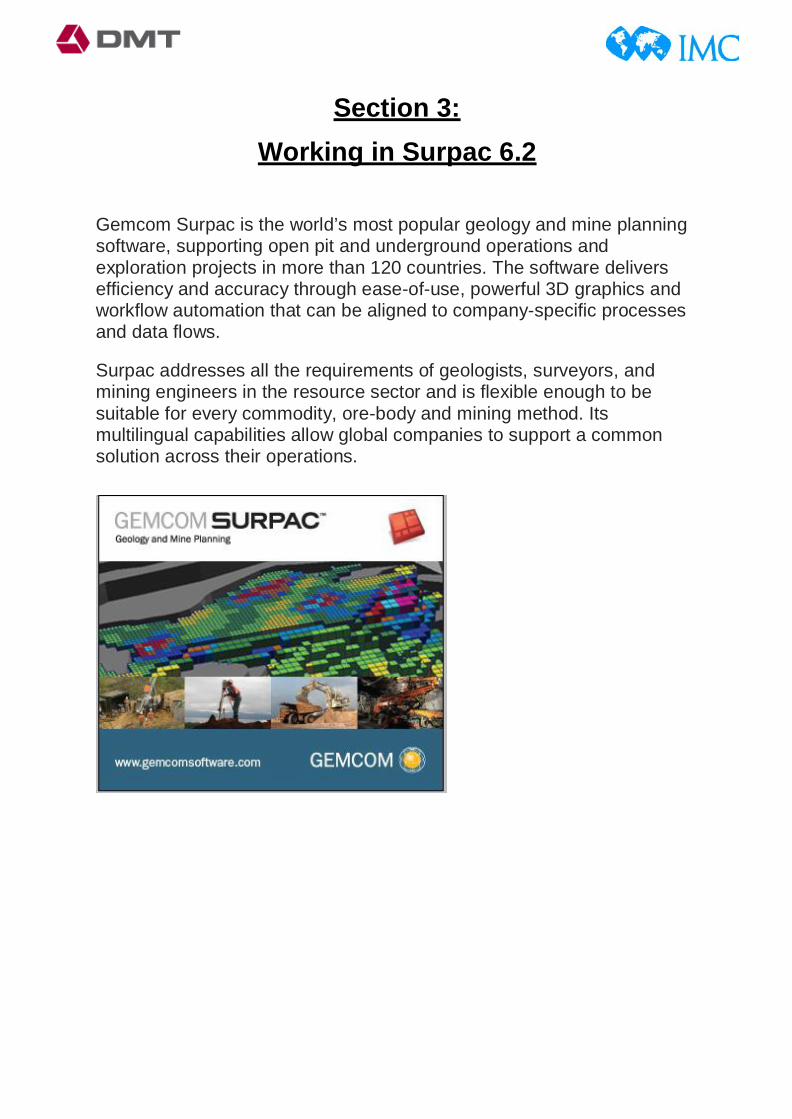
Gemcom Surpac is the world’s most popular geology and mine planning software, supporting open pit and underground operations and exploration projects in more than 120 countries. The software delivers efficiency and accuracy through ease-of-use, powerful 3D graphics and workflow automation that can be aligned to company-specific processes and data flows.
Surpac addresses all the requirements of geologists, surveyors, and mining engineers in the resource sector and is flexible enough to be suitable for every commodity, ore-body and mining method. Its multilingual capabilities allow global companies to support a common solution across their operations.
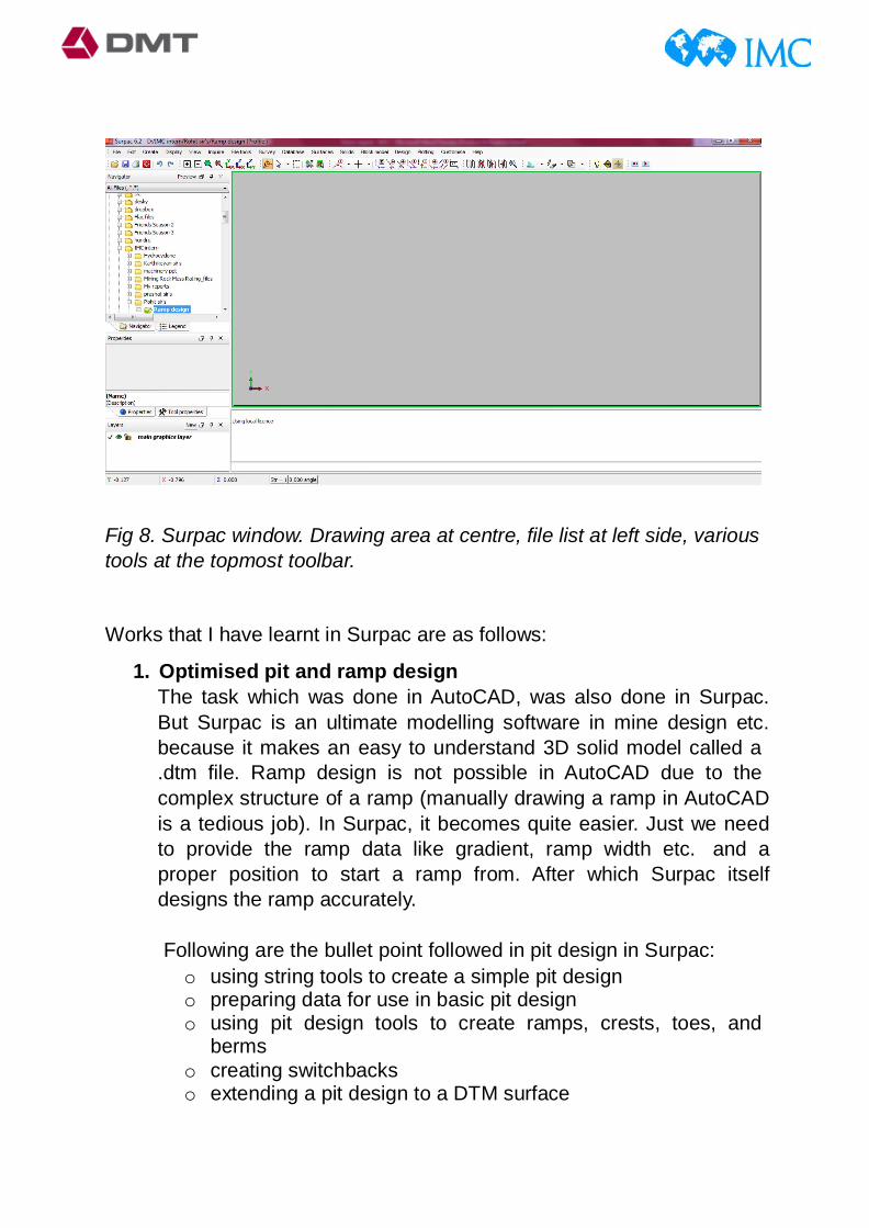
Fig 8. Surpac window. Drawing area at centre, file list at left side, various tools at the topmost toolbar.
Works that I have learnt in Surpac are as follows:
1. Optimised pit and ramp design The task which was done in AutoCAD, was also done in Surpac. But Surpac is an ultimate modelling software in mine design etc. because it makes an easy to understand 3D solid model called a .dtm file. Ramp design is not possible in AutoCAD due to the complex structure of a ramp (manually drawing a ramp in AutoCAD is a tedious job). In Surpac, it becomes quite easier. Just we need to provide the ramp data like gradient, ramp width etc. and a proper position to start a ramp from. After which Surpac itself designs the ramp accurately.
Following are the bullet point followed in pit design in Surpac: o using string tools to create a simple pit design o preparing data for use in basic pit design o using pit design tools to create ramps, crests, toes, and
berms o creating switchbacks o extending a pit design to a DTM surface

Ore body data of GFL, Morocco project was given to me (in form of Surpac string files of optimised pit cross-sections at various levels). From this data, I made following 3D pit model, including ramps.
Fig9. Plan view of the designed pit.
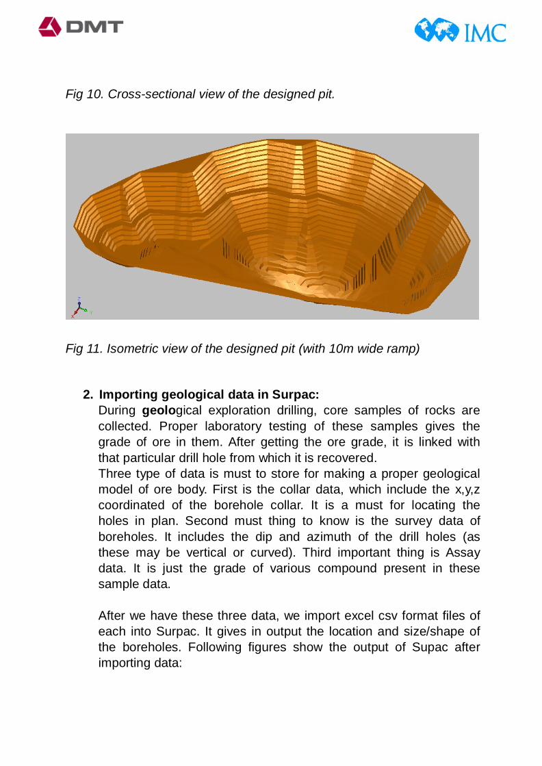
Fig 10. Cross-sectional view of the designed pit.
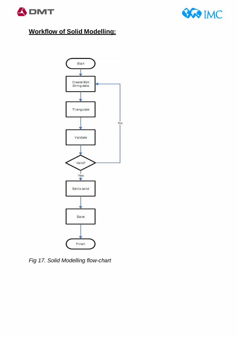
Fig 11. Isometric view of the designed pit (with 10m wide ramp)
2. Importing geological data in Surpac: During geological exploration drilling, core samples of rocks are collected. Proper laboratory testing of these samples gives the grade of ore in them. After getting the ore grade, it is linked with that particular drill hole from which it is recovered. Three type of data is must to store for making a proper geological model of ore body. First is the collar data, which include the x,y,z coordinated of the borehole collar. It is a must for locating the holes in plan. Second must thing to know is the survey data of boreholes. It includes the dip and azimuth of the drill holes (as these may be vertical or curved). Third important thing is Assay data. It is just the grade of various compound present in these sample data.
After we have these three data, we import excel csv format files of each into Surpac. It gives in output the location and size/shape of the boreholes. Following figures show the output of Supac after importing data:

Fig 12. Plan view of boreholes (marked) in Surpac after importing data.
Fig 13. Cross-section of boreholes.

3. Solid Modelling Solids Modelling allows us to use triangulation to create three- dimensional models based on DigitalTerrain Models (DTMs) and String files. Basically if we have different planes or surfaces and we want to join them to form a single solid body, Surpac works here very well.
This is termed as solid modelling. I was given with the same borehole data shown in previous section. Also I was given with the topography of that area. From this I made various sections of ore- bogy using the bore holes plotted. Total seven sections were drawn, which looks like this:
Fig 14. Isometric view of 7 ore-body sections and boreholes.

After this, using the triangulation technique, we can make a solid ore body model in Surpac. It is as shown below:
Fig 15. Solid model (same view as previous figure’s).
Fig 16. Triangulation of sections (isometric view).
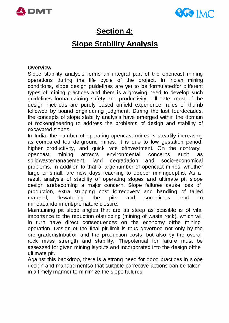
Workflow of Solid Modelling:
Fig 17. Solid Modelling flow-chart
Section 4:
Slope Stability Analysis
Overview Slope stability analysis forms an integral part of the opencast mining operations during the life cycle of the project. In Indian mining conditions, slope design guidelines are yet to be formulatedfor different types of mining practices and there is a growing need to develop such guidelines formaintaining safety and productivity. Till date, most of the design methods are purely based onfield experience, rules of thumb followed by sound engineering judgment. During the last fourdecades, the concepts of slope stability analysis have emerged within the domain of rockengineering to address the problems of design and stability of excavated slopes. In India, the number of operating opencast mines is steadily increasing as compared tounderground mines. It is due to low gestation period, higher productivity, and quick rate ofinvestment. On the contrary, opencast mining attracts environmental concerns such as solidwastemanagement, land degradation and socio-economical problems. In addition to that a largenumber of opencast mines, whether large or small, are now days reaching to deeper miningdepths. As a result analysis of stability of operating slopes and ultimate pit slope design arebecoming a major concern. Slope failures cause loss of production, extra stripping cost forrecovery and handling of failed material, dewatering the pits and sometimes lead to mineabandonment/premature closure. Maintaining pit slope angles that are as steep as possible is of vital importance to the reduction ofstripping (mining of waste rock), which will in turn have direct consequences on the economy ofthe mining operation. Design of the final pit limit is thus governed not only by the ore gradedistribution and the production costs, but also by the overall rock mass strength and stability. Thepotential for failure must be assessed for given mining layouts and incorporated into the design ofthe ultimate pit. Against this backdrop, there is a strong need for good practices in slope design and managementso that suitable corrective actions can be taken in a timely manner to minimize the slope failures.

Objectives The prime objectives of the project are addressed towards: a) Understanding the different types and modes of slope failures; and b) Designing of stable slopes for opencast mines using numerical models.
Factors Affecting Slope Stability Slope failures of different types are affected by the following factors:
1. Slope Geometry The basic geometrical slope design parameters are height, overall slope angle and area of failuresurface. With increase in height the slope stability decreases. The overall angle increases thepossible extent of the development of the any failure to the rear of the crests increases and itshould be considered so that the ground deformation at the mine peripheral area can be avoided. Generally overall slope angle of 45° is considered to be safe by Directorate General of MinesSafety (DGMS). The curvature of the slope has profound effect on the instability and thereforeconvex section slopes should be avoided in the slope design. Steeper and higher the height ofslope less is the stability. Diagram showing bench, ramp, overall slope and their respectiveangles is given in Fig. 2.1.
Fig 18. Diagram showing bench, ramp, overall slope and their respective angles.

2. Geological Structure The main geological structure which affect the stability of the slopes in the open pit mines are: 1. Amount and direction of dip 2. Intra-formational shear zones
3. Joints and discontinuities a) Reduce shear strength b) Change permeability c) Act as sub surface drain and plains of failure
4. Faults a) Weathering and alternation along the faults b) Act as ground water conduits c) Provides a probable plane of failure
Fig 19. Different types of joints and faults.
Instability may occur if the strata dip into the excavations. Faulting provides a lateral or rearrelease plane of low strength and such strata plan are highly disturbed. Localized steepening ofstrata is critical for the stability of the slopes. If a clay band comes in between the two rockbands, stability is hampered. Joints and bedding planes also provide surfaces of weakness. Stability of the slope is dependent on the shear strength available along such surface, on theirorientations in relation to the slope and water pressure action on the surface. These shear strengththat can be

mobilized along joint surface depending on the functional properties of the surfaceand the effective stress which are transmitted normal to the surface. Joints can create a situationwhere a combination of joint sets provides a cross over surface.
5. Lithology The rock materials forming a pit slope determines the rock mass strength modified bydiscontinuities, faulting, folding, old workings and weathering. Low rock mass strength ischaracterized by circular; ravelling and rock fall instability like the formation of slope in massivesandstone restrict stability. Pit slopes having alluvium or weathered rocks at the surface have lowshearing strength and the strength gets further reduced if water seepage takes place throughthem. These types of slopes must be flatter.
6. Ground Water It causes the following: a) Alters the cohesion and frictional parameters and b) Reduce the normal effective stress Ground water causes increased up thrust and driving water forces and has adverse effect on thestability of the slopes. Physical and chemical effect of pure water pressure in joints fillingmaterial can thus alter the cohesion and friction of the discontinuity surface. Physical effects ofproviding uplift on the joint surface, reduces the frictional resistances. This will reduce theshearing resistance along the potential failure plane by reducing the effective normal stressacting on it. Physical and the chemical effect of the water pressure in the pores of the rock causea decrease in the compressive strength particularly where confining stress has been reduced.
7. Mining Method and Equipment Generally there are four methods of advance in open cast mines. They are: (a) Strike cut- advancing down the dip (b) Strike cut- advancing up the dip (c) Dip cut- along the strike (d) Open pit working The use of dip cuts with advance on the strike reduces the length and time that a face is exposedduring excavation. Dip cuts with advance oblique to strike may often be used to reduce the stratadip in to the excavation. Dip cut generally offer the most stable method of working but sufferfrom restricted production potential. Open pit method are used in steeply dipping seams, due tothe increased slope height are more
prone to large slab/buckling modes of failure. Miningequipment which piles on the benches of the open pit mine gives rise to the increase in surchargewhich in turn increases the force which tends to pull the slope face downward and thus instabilityoccurs. Cases of circular failure in spoil dumps are more pronounced.
8. Dynamic Forces Due to effect of blasting and vibration, shear stresses are momentarily increased and as resultdynamic acceleration of material and thus increases the stability problem in the slope face. Itcauses the ground motion and fracturing of rocks. Blasting is a primary factor governing the maximum achievable bench face angles. The effects ofcareless or poorly designed blasting can be very significant for bench stability, as noted by Sage(1976) and Bauer and Calder (1971). Besides blast damage and back break which both reducethe bench face angle, vibrations from blasting could potentially cause failure of the rock mass. Forsmall scale slopes, various types of smooth blasting have been proposed to reduce these effectsand the experiences are quite good (e.g. Hoek and Bray, 1981). For large scale slopes, however,blasting becomes less of problem since back break and blast damage of benches have negligibleeffects on the stable overall slope angle. Furthermore, the high frequency of the blast accelerationwaves prohibit them from displacing large rock masses uniformly, as pointed out by Bauer andCalder (1971). Blasting-induced failures are thus a marginal problem for large scale slopes. Seismic events, i.e., low frequency vibrations, could be more dangerous for large scale slopes andseveral seismic-induced failures of natural slopes have been observed in mountainous areas. Together with all these causes external loading can also plays an important role when they arepresent as in case of surcharge due to dumps on the crest of the benches. In high altitude areas,freezing of water on slope faces can results in the build-up of ground water pressure behind the face which again adds up to instability of the slope.
9. Cohesion It is the characteristic property of a rock or soil that measures how well it resists being deformedor broken by forces such as gravity. In soils/rocks true cohesion is caused by electrostatic forcesin stiff over consolidated clays, cementing by Fe2O3, CaCO3, NaCl, etc. and root cohesion. However the apparent cohesion is caused by negative capillary pressure and pore pressureresponse during untrained loading. Slopes having

rocks/soils with less cohesion tend to be lessstable. The factors that strengthen cohesive force are as follows: a) Friction b) Stickiness of particles can hold the soil grains together. However, being too wet or toodry can reduce cohesive strength. c) Cementation of grains by calcite or silica deposition can solidify earth materials intostrong rocks. d) Man-made reinforcements can prevent some movement of material.
The factors that weaken cohesive strength are as follows: a) High water content can weaken cohesion because abundant water both lubricates (Overcoming friction) and adds weight to a mass. b) Alternating expansion by wetting and contraction by drying of water reduces strength ofcohesion, just like alternating expansion by freezing and contraction by thawing. Thisrepeated expansion is perpendicular to the surface and contraction vertically by gravityovercomes cohesion resulting with the rock and sediment moving slowly downhill. c) Undercutting in slopes d) Vibrations from earthquakes, sonic booms, blasting that create vibrations whichovercome cohesion and cause mass movement.
10. Angle of Internal Friction Angle of internal friction is the angle, measured between the normal force (N) and resultantforce (R), that is attained when failure just occurs in response to a shearing stress (S). Its tangent(S/N) is the coefficient of sliding friction. It is a measure of the ability of a unit of rock or soil towithstand a shear stress. This is affected by particle roundness and particle size. Lowerroundness or larger median particle size results in larger friction angle. It is also affected byquartz content. The sands with less quartz contained greater amounts of potassium- feldspar,plagioclase, calcite, and/or dolomite and these minerals generally have higher sliding frictionalresistance compared to that of quartz.
Types of Slope Failure
1. Plane Failure Simple plane failure is the easiest form of rock slope failure to analyse. It occurs when adiscontinuity striking approximately parallel to the slope face and dipping at a lower angleintersects the slope face, enabling the material above the discontinuity to slide. Variations on thissimple failure

mode can occur when the sliding plane is a combination of joint sets which form astraight path. This means that the solution is never anything more than the analysis of equilibrium of a singleblock resting on a plane and acted upon by a number of external forces (water pressure, earthquake, etc.) deterministic and probabilistic solution in which parameters are considered as beingprecisely known may be readily obtained by hand calculation if effect of moment is neglected.
Fig 20. Plane failure.
2. Wedge Failure The three dimensional wedge failures occur when two discontinuities intersects in such a way that the wedge of material, formed above the discontinuities, can slide out in a direction parallel to the line of intersection of the two discontinuities. It is particularly common in the individual bench scale but can also provide the failure mechanism for a large slope where structures are very continuous and extensive.

Fig 21. Wedge failure.
When two discontinuities strike obliquely across the slope face and their line of intersection ‘daylights’ in the slope, the wedge of the rock resting over these discontinuities will slide down along the line of intersection provided the inclination of these line is significantly greater than the angle of friction and the shearing component of the plane of the discontinuities is less than the total downward force. The total downward force is the downward component of the weight of the wedge and the external forces (surcharges) acting over the wedge.
3. Circular Failure The pioneering work, in the beginning of the century, in Sweden confirmed that the surface of the failure in spoil dumps or soil slopes resembles the shape of a circular arc. This failure can occurs in soil slopes, the circular method occurs when the joint sets are not very well defined. When the material of the spoil dump slopes are weak such as soil, heavily jointed or broken rock mass, the failure is defined by a single discontinuity surface but will tend to follow a circular path. The conditions under which circular failure occurs are follows: 1. When the individual particles of soil or rock mass, comprising the slopes are small as compared to the slope. 2. When the particles are not locked as a result of their shape and tend to behave as soil.

Fig 22. Three-dimensional failure geometry of a rotational shear failure.
Types of circular failure Circular failure is classified in three types depending on the area that is affected by the failure surface. They are:- (a) Slope failure: In this type of failure, the arc of the rupture surface meets the slope above the toe of the slope. This happens when the slope angle is very high and the soil close to the toe possess the high strength. (b) Toe failure: In this type of failure, the arc of the rupture surface meets the slope at the toe. (c) Base failure: In this type of failure, the arc of the failure passes below the toe and in to base of the slope. This happens when the slope angle is low and the soil below the base is softer and more plastic than the soil above the base.
4. Two Block Failure Two block failures are much less common mode of rock slope failure than single block failures such as the planes and the 3D wedge and, consequently, are only briefly considered here. Several methods of solution exist and each may be appropriate at some level of investigation.
5. Toppling Failure Toppling or overturning has been recognized by several investigators as being a mechanism of rock slope failure and has been postulated as the cause of several failures ranging from small to large ones.
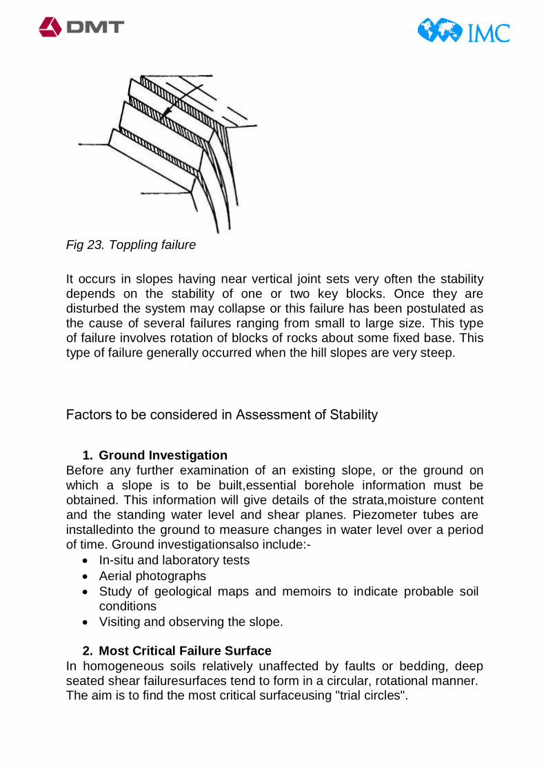
Fig 23. Toppling failure
It occurs in slopes having near vertical joint sets very often the stability depends on the stability of one or two key blocks. Once they are disturbed the system may collapse or this failure has been postulated as the cause of several failures ranging from small to large size. This type of failure involves rotation of blocks of rocks about some fixed base. This type of failure generally occurred when the hill slopes are very steep.
Factors to be considered in Assessment of Stability
1. Ground Investigation Before any further examination of an existing slope, or the ground on which a slope is to be built,essential borehole information must be obtained. This information will give details of the strata,moisture content and the standing water level and shear planes. Piezometer tubes are installedinto the ground to measure changes in water level over a period of time. Ground investigationsalso include:-
• In-situ and laboratory tests • Aerial photographs • Study of geological maps and memoirs to indicate probable soil
conditions • Visiting and observing the slope.
2. Most Critical Failure Surface In homogeneous soils relatively unaffected by faults or bedding, deep seated shear failuresurfaces tend to form in a circular, rotational manner. The aim is to find the most critical surfaceusing "trial circles".

The method is as follows: • A series of slip circles of different radii is to be considered but with
same centre ofrotation. Factor of Safety (FOS) for each of these circles is plotted against radius, and theminimum FOS is found.
• This should be repeated for several circles, each investigated from an array of centers.The simplest way to do this is to form a rectangular grid from the centers.
• Each centre will have a minimum FOS and the overall lowest FOS from all the centreshows that FOS for the whole slope. This assumes that enough circles, with a largespread of radii, and a large grid of centers have been investigated.
• An overall failure surface is found. Below figures shows variety of slope failure circles analysed at varying radii from a singlecentre and variation of factor of safety with critical circle radius respectively.
Fig 24. Variety of slope failure circles analysed at varying radii from a single centre

Fig 25. Variation of factor of safety with critical circle radius
3. Tension Cracks A tension crack at the head of a slide suggests strongly that instability is imminent. Tensioncracks are sometimes used in slope stability calculations, and sometimes they are considered tobe full of water. If this is the case, then hydrostatic forces develop as shown in Fig.
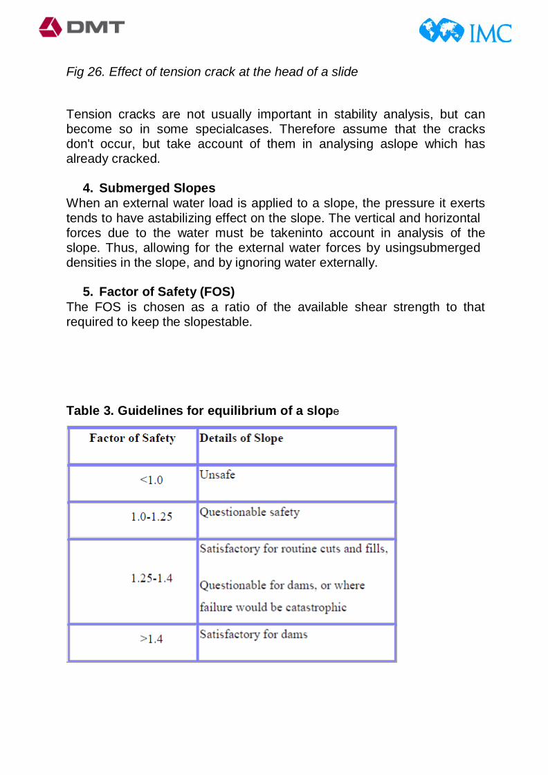
Fig 26. Effect of tension crack at the head of a slide
Tension cracks are not usually important in stability analysis, but can become so in some specialcases. Therefore assume that the cracks don't occur, but take account of them in analysing aslope which has already cracked.
4. Submerged Slopes When an external water load is applied to a slope, the pressure it exerts tends to have astabilizing effect on the slope. The vertical and horizontal forces due to the water must be takeninto account in analysis of the slope. Thus, allowing for the external water forces by usingsubmerged densities in the slope, and by ignoring water externally.
5. Factor of Safety (FOS) The FOS is chosen as a ratio of the available shear strength to that required to keep the slopestable.
Table 3. Guidelines for equilibrium of a slope

For highly unlikely loading conditions, factors of safety can be as low as 1.2-1.25, even for dams. E.g. situations based on seismic effects, or where there is rapid drawdown of the water level in a reservoir.
6. Progressive Failure This is the term describing the condition when different parts of a failure surface reach failure atdifferent times. This often occurs if a potential failure surface passes through a foundationmaterial which is fissured or has joints or pre-existing failure surfaces. Where these fissuresoccur there will be large strain values, so the peak shear strength is reached before other places.
7. Pre-Existing Failure Surfaces If the foundation on which a slope sits contains pre-existing failure surfaces, there is a largepossibility that progressive failure will take place if another failure surface were to cut throughthem. The way to deal with this situation is to assume that sufficient movement has previouslytaken place for the ultimate state to develop in the soil and then using the ultimate stateparameters. If failure has not taken place, then a decision has to be made on which parameters tobe used.
The numerical modelling portion of slope stability analysis was not carried out due to time constraints. Hence I will try to do that analysis after joining my institute, as a future scope of work.
References
1. Classifications of Rock Masses for engineering: The RMR system and Future Trends, by Z. T. Bieniawski, Pennsylvania State University, USA.
2. Geotechnical considerations in underground mines, Guideline, Moshab approved, December 1997, Document No: ZME723QT.
3. Handbook of Geotechnical Investigationand Design Tables, by Burt G. LookConsulting Geotechnical Engineer.
4. Pit Design Tutorial, Surpac 6.3by Gemcom.
5. Design of stable slope for opencast mines, B.Tech. Project Thesis, B. B. Prakash, NIT Rourkela.