Interim Management Plan for Excavation Dewatering...
70
The world's leading sustainability consultancy Interim Management Plan for Excavation Dewatering North Pole Sulfolane Plume FINAL July 2014 Prepared on Behalf of Alaska Department of Environmental Conservation By ERM Alaska, Inc. 825 West 8th Avenue Anchorage, Alaska 99501 T: (907) 258-4880 F: (907) 258-4033
Transcript of Interim Management Plan for Excavation Dewatering...

The world's leading sustainability consultancy
Interim Management Plan for Excavation Dewatering
North Pole Sulfolane Plume
FINAL
July 2014
Prepared on Behalf of
Alaska Department of Environmental Conservation
By ERM Alaska, Inc.
825 West 8th Avenue Anchorage, Alaska 99501
T: (907) 258-4880 F: (907) 258-4033

- Page Intentionally Left Blank -

North Pole Sulfolane Plume Interim Excavation Dewatering Management Plan ADEC
ERM i 7/20/2014
TABLE OF CONTENTS
DEFINITIONS ............................................................................................................................ iii
1. INTRODUCTION.................................................................................................................. 1 1.1. Purpose and Application ............................................................................................. 1 1.2. Interim Document ........................................................................................................ 2
1.2.1. Scope and Purpose ............................................................................................ 2 1.2.2. Organization ...................................................................................................... 3 1.2.3. Use....................................................................................................................... 3
1.3. Final Document ............................................................................................................. 4 1.4. Permit and Agency Coordination .............................................................................. 5
1.4.1. ADEC Division of Water.................................................................................. 5 1.4.2. Notice of Intent and BMP Plan Requirements .............................................. 5 1.4.3. North Pole MS4 Permit Coordination ............................................................ 5 1.4.4. Alaska Department of Natural Resources ..................................................... 5 1.4.5. Alaska Department of Fish and Game ........................................................... 6 1.4.6. Landowner Permission and Coordination .................................................... 6
2. NORTH POLE SULFOLANE PLUME ............................................................................... 7 2.1. Contaminant Plume ..................................................................................................... 7 2.2. Treatment ....................................................................................................................... 8 2.3. Hydrogeology ............................................................................................................... 9 2.4. Project Area GIS Map ................................................................................................. 13
3. EXCAVATION DEWATERING BMP PLAN ................................................................. 15 3.1. BMP Plan Requirements ............................................................................................ 15 3.2. Water Balance Management Methods ..................................................................... 16 3.3. Estimate of Dewatering Production Rate and Volume ......................................... 16 3.4. Excavation Dewatering BMPs .................................................................................. 17
3.4.1. Groundwater Control by Pumping .............................................................. 17 3.4.2. Groundwater Control by Exclusion ............................................................. 18 3.4.3. Surface Water Control .................................................................................... 18
3.5. Land Surface Discharge BMPs .................................................................................. 19
4. REFERENCES ....................................................................................................................... 21
TABLES Table 1: Water Table Elevations and Depth to Groundwater for Selected Locations
Within the Sulfolane Plume ...................................................................................... 10 Table 2: Summary of Aquifer Parameters from 2013 Pumping Test (Barr 2013) ......... 12
APPENDICES
A: North Pole Sulfolane Plume and Hydrogeology Figures B: Land Surface Discharge Best Management Practices (BMPs)

North Pole Sulfolane Plume Interim Excavation Dewatering Management Plan ADEC
ERM ii 7/20/2014
- Page Intentionally Left Blank -

North Pole Sulfolane Plume Interim Excavation Dewatering Management Plan ADEC
ERM iii 7/20/2014
DEFINITIONS
Acronyms APDES ............ Alaska Pollutant Discharge Elimination System AQTESOLV™ AQuifer TEst SOLVer is software for analyzing aquifer pumping tests BMPs ............... Best Management Practices are schedules of activities, prohibitions of
practices, maintenance procedures, and structural and/or managerial practices, that when used singly or in combination, prevent or reduce the release of pollutants and other adverse impacts to waters of United States.
bgs ................... below ground surface FHR ................. Flint Hills Resources GIS .................. geographic information system MS4 ................. Municipal Separate Storm Sewer Systems NOI ................. Notice of Intent NPR................. North Pole Refinery SWPPP ............ Stormwater Pollution Prevention Plan WWTF ............ North Pole Wastewater Treatment Facility Hydrogeology Terminology drawdown ..... Change in hydraulic head in a well due to pumping hydraulic gradient .......... Change in hydraulic head over distance. It is measured in units of length
per length (e.g., feet/foot) infiltration ...... The process by which water on the ground surface enters the soil.
Infiltration rate in soil science is a measure of the rate at which soil is able to absorb rainfall or ponded water on the ground surface and is typically measured in inches per hour.
K ...................... Hydraulic Conductivity is a measure of an aquifer’s ability to transmit water or another fluid. It is measured in units of length per time (e.g., ft/day)
Sc ..................... Aquifer Storage Coefficient or Storativity; in an unconfined aquifer is approximately equal to Specific Yield, which is the Volume of water released from storage per unit surface area of aquifer per unit decline of the water table. It is unitless.
Specific Capacity ......... A measure of water well productivity; specific capacity is the amount of
water a well can produce per unit of drawdown T ...................... Transmissivity is a measure of the amount of water an aquifer can
transmit through a given cross-sectional area. It is measured in units of length squared per time (e.g., ft2/day). Transmissivity is related to hydraulic conductivity by the following relationship: T=Kb, where K=hydraulic conductivity and b=saturated aquifer thickness.
North Pole Sulfolane Plume Interim Excavation Dewatering Management Plan ADEC
ERM iv 7/20/2014
Units of Measurement µg/L ................ micrograms per liter, equivalent to parts per billion (ppb) ft/d ................. feet per day ft2/d ................ square feet per day gpd .................. gallons per day gpm ................. gallons per minute

North Pole Sulfolane Plume Interim Excavation Dewatering Management Plan ADEC
ERM v 7/20/2014
- Page Intentionally Left Blank -

North Pole Sulfolane Plume Interim Excavation Dewatering Management Plan ADEC
ERM 1 7/20/2014
1. INTRODUCTION
Releases of sulfolane at the North Pole Refinery (NPR) have resulted in a contaminated groundwater plume that extends throughout much of the City of North Pole, Alaska, and beyond the city boundaries. The potential exists for development as well as utility maintenance projects within North Pole and beyond to be severely impacted by the logistics for managing excavations that require dewatering within the sulfolane plume boundary. A plan for managing excavation dewatering fluids in compliance with applicable regulations is necessary to reduce impacts on projects in North Pole and surrounding impacted areas.
1.1. Purpose and Application This Interim Excavation Dewatering Management Plan provides guidance for managing excavation water generated during construction dewatering activities in the vicinity of the North Pole sulfolane groundwater plume. The overarching management goals are to minimize the volume of contaminated water to be discharged and to manage the discharge so that it does not cause sulfolane contamination in areas that were previously uncontaminated. This is an interim document to be used during the 2014 construction season. After the 2014 construction season has concluded, this interim plan will be replaced by a final management plan.
The dewatering activities addressed by this document are those that meet the requirements of and are permitted under the Alaska Pollutant Discharge Elimination System (APDES) General Permit AKG002000 that will replace the expired State of Alaska Wastewater General Dewatering Permit 2009DB0003. As of July 18, 2014, the general permit AKG002000 is publicly available and will become effective on August 1, 2014.
THE APPLICANT SHOULD VERIFY REFERENCES TO PROPOSED FINAL PERMIT AKG002000 IN THIS INTERIM MANAGEMENT PLAN FOR CONSISTENCY WITH INFORMATION IN THE FINAL PERMIT.
In accordance with Section 2.2.1 of the Final - General Permit AKG002000, a Notice of Intent (NOI) and a certified Best Management Practices (BMP) Plan are required for any proposed excavations within 1,500 feet of a contaminated site or contaminated groundwater plume. The NOI and BMP must be submitted at least 30 days prior to the proposed dewatering date; and approval must be received from the Division of Water before commencing with dewatering activities. This document is intended to assist contractors with the application process and provide additional resources for complying with the NOI and BMP requirements for excavations proposed within 1,500 feet of the North Pole Sulfolane Plume. The North Pole Sulfolane Plume is defined as including the following areas: Fairbanks Meridian Township 1S/ Range 2E/ Sections 31, 32, and 33; Township 2S/ Range 2E/ Sections 4, 5, 6, 7, 8, 9, 16, and 17.
North Pole Sulfolane Plume Interim Excavation Dewatering Management Plan ADEC
ERM 2 7/20/2014
1.2. Interim Document
1.2.1. Scope and Purpose
The goal of the Interim Excavation Dewatering Management Plan is to allow construction activities requiring dewatering within the North Pole sulfolane plume to proceed during the 2014 construction season while progress is made to resolve key limitations in the science and regulatory arenas that are currently inhibiting completion of a final management plan. This interim plan provides one option (with several variations) for managing excavation dewatering discharge that is contaminated with sulfolane and presents appropriate BMPs to manage the discharge. This interim management plan is intended for use during the 2014 construction season only; it will then be replaced by a final management plan. The key limitations that led to preparation of this interim document are summarized below.
• For the 2014 construction season, any dewatering discharge with sulfolane detections above the method reporting limit1 will require evaluation for management in accordance with this interim document. The cleanup level for sulfolane is currently under review, and a final decision on this level is expected after the 2014 construction season. Once a cleanup level is established, it will be incorporated into the final excavation dewatering guidance document.
• For the 2014 construction season, one option has been identified for management of water from excavation dewatering projects within the sulfolane plume: discharge to land, with several variations based on the actual excavation location. There is currently no proven technology that is practical for treating sulfolane contamination prior to discharge in an excavation dewatering situation. Treatment at the City of North Pole Wastewater Treatment Facility (WWTF) may be a feasible option in future construction seasons. Due to treatment facility renovations, the WWTF cannot accept any excavation dewatering discharge during the 2014 construction season. Therefore, the interim option for managing sulfolane-contaminated excavation dewatering volume is land discharge within the plume boundaries such that the plume is not affected2.
• During summer of 2014, field verification activities are planned to (1) further confirm that land discharge within the plume area is the best alternative and (2) investigate other discharge alternatives, such as discharge to a gravel pit. In addition, other discharge options that may be available after the 2014 construction season include discharge to the North Pole WWTF under their industrial wastewater pretreatment program. After the 2014 construction season, the interim management option will be reviewed in consideration of new information, and a final management plan will be prepared.
1 The method reporting limit is somewhat variable but expected to be approximately 7 micrograms per liter (µg/L) for groundwater samples collected in North Pole outside of the refinery property. 2 Sulfolane has a low affinity for adsorption onto soil particles and therefore preferentially remains dissolved in water rather than attaching itself to soil (see Section 2).

North Pole Sulfolane Plume Interim Excavation Dewatering Management Plan ADEC
ERM 3 7/20/2014
• The excavation dewatering general permit 2009DB0003 expired in March 2014, and the new excavation dewatering general permit AKG002000 will be effective on August 1, 2014. This interim management plan includes a discussion of the requirements for the new permit.
1.2.2. Organization
This Interim Excavation Dewatering Management Plan is organized into the sections described below.
Section 1: Introduction
Section 1.1 discusses the purpose and application of the excavation dewatering management plan and its division into interim and final plans.
Section 1.2 summarizes the additional permit and agency coordination requirements per Final - General Permit for Excavation Dewatering AKG002000.
Section 2: North Pole Sulfolane Plume NOI Information
Section 2 provides a description of the North Pole Sulfolane Plume and the hydrogeology of the plume area. The text in Section 2 meets MOST of the NOI requirements required by Section 2.2.7.1 and specified by Section 2.2.7.3 of Final - General Permit AKG002000. Sections of the permit are referenced under each applicable topic.
Section 3: Excavation Dewatering BMP Plan
Section 3 provides a summary of the BMP Plan requirements per Section 2.2.8 of the Final - General Permit AKG002000.
Appendix A: North Pole Sulfolane Plume and Hydrogeology Maps and Figures
Appendix A provides maps from published reports to accompany the discussion in Section 2. Appendix A includes maps of the North Pole sulfolane plume and relevant hydrogeologic information, such as depth to permafrost, groundwater flow directions, groundwater table contour maps, and distribution of hydraulic conductivity.
Appendix B: Excavation Dewatering Land Surface Discharge BMPs
Appendix B provides BMPs for excavation dewatering land surface discharge.
1.2.3. Use
This Interim Management Plan for Excavation Dewatering is intended to assist North Pole Sulfolane Plume applicants with the application process by providing additional guidance and some of the information required to complete the application process.
Authorization to discharge under the Excavation Dewatering General Permit requires applicants seeking authorization to submit a completed NOI and certified BMP Plan to ADEC in accordance with the requirements listed in Section 2.2 of the General Permit.

North Pole Sulfolane Plume Interim Excavation Dewatering Management Plan ADEC
ERM 4 7/20/2014
The NOI may be submitted electronically via the Permit Application Portal at: http://www.dec.alaska.gov/water/wnpspc/stormwater/APDESeNOI.html or by completing a paper form found at http://dec.alaska.gov/water/wnpspc/stormwater/Forms.htm and sent to the ADEC Permitting Program address located in the Permit Appendix A, Part 1.1.1. When the permit is issued, the Excavation Dewatering NOI’s will be accessible via search at: http://dec.alaska.gov/Applications/Water/WaterPermitSearch/Search.aspx.
For more information on the Excavation Dewatering Permit, please see the following ADEC Division of Water webpage: http://dec.alaska.gov/Water/wnpspc/stormwater/edhsgp.html which will have the permit and other resources for applicant/permittee.
The certified BMP Plan that describes how the wastewater will be managed with a description of each BMP to be implemented on site must meet all the requirements listed in Section 2.2.8 of the Excavation Dewatering General Permit. Additional details and example BMPs are provided in Section 3.0 of this Interim Management Plan.
1.3. Final Document As described in Section 1.2.1, the results of activities performed during the 2014 construction season will be used to create a final excavation dewatering management plan. The final excavation dewatering management plan is expected to fill the following gaps in this interim plan.
• Incorporate the final sulfolane cleanup level, when established.
• Incorporate results from the field verification study to modify the existing alternative (land discharge), if appropriate, and to identify new alternatives, if appropriate.
• Include a decision tree to help applicants select the best excavation dewatering management method for a given excavation.
• Include relevant permitting information from the new excavation dewatering permit, if available.
• Include a water balance calculator to assist the applicant in estimating the volume of excavation dewatering that needs to be managed, as well as the infiltration rate for land discharge options.
• Include an option for treatment of wastewater prior to discharge, if mechanisms for treatment have been proven to be scientifically valid and economically feasible.
North Pole Sulfolane Plume Interim Excavation Dewatering Management Plan ADEC
ERM 5 7/20/2014
1.4. Permit and Agency Coordination Excavation dewatering operations in the vicinity of the North Pole sulfolane groundwater plume area will require the coordination and permitting from multiple agencies. The list of agencies and their applicability is provided in this section.
1.4.1. ADEC Division of Water
The Excavation Dewatering General Permit (AKG002000) is administered by the Division of Water. This general permit applies to a wastewater discharge from excavation on sites located less than 1,500 feet from a contaminated site. If the construction activities will disturb more than one acre of land then the APDES General Permit for Storm Discharges from Large and Small Construction Activity (ACGP) will also apply. Details regarding the ACGP will not be covered in this document.
1.4.2. Notice of Intent and BMP Plan Requirements
A Notice of Intent and BMP Plan are required for all Excavation Dewatering permits that will be located within 1,500 feet of a “DEC-identified contaminated site or groundwater plume”. A Notice of Intent and BMP Plan are also required for excavation dewatering discharges to waters of U.S. that are not eligible for coverage under the Construction General Permit (AKR100000) even if they are outside the 1,500 feet distance.
A Notice of Intent is not required for excavation dewatering discharges to the land greater than 1,500 feet from a “DEC-contaminated site or groundwater plume”.
1.4.3. North Pole MS4 Permit Coordination
Excavation dewatering discharges that enter the City of North Pole or Fairbanks North Star Borough (FNSB) storm water conveyance systems (including roadside ditches) come under jurisdiction of the APDES Permit for Storm Water Discharges from Small Municipal Separate Storm Sewer Systems (MS4s)3. For excavation dewatering discharges using the North Pole or FNSB storm water conveyance systems, review and approval for the Excavation Dewatering permit must also be granted by the City of North Pole and/or FNSB to temporarily disconnect the conveyance system.
1.4.4. Alaska Department of Natural Resources
Excavation dewatering operations that will withdraw 30,000 gallons per day (gpd) of water or more will need to contact the Alaska Department of Natural Resources – Division of Mining, Land, and Water 60 days in advance to determine if a Temporary Water Use Authorization is required.
3 See Fairbanks Storm Water Management Program Contacts Info Page for Fairbanks North Star Borough and City of North Pole, http://www.co.fairbanks.ak.us/PWorks/StormWaterManagementProgram/contacts.htm

North Pole Sulfolane Plume Interim Excavation Dewatering Management Plan ADEC
ERM 6 7/20/2014
1.4.5. Alaska Department of Fish and Game
A fish habitat permit will not be required as excavation dewatering discharges in the North Pole contaminated groundwater plume area will not be allowed into any waters of the U.S. (surface water body).
1.4.6. Landowner Permission and Coordination
The preferred alternative is for onsite discharge of excavation dewatering discharges. However, if this is not possible another alternative is to discharge accumulated water to adjacent public or private land. For discharges to private land a written agreement with the landowner is required.
General requirements also include the following:
• The discharge must be managed so that it cannot discharge to a storm drain or surface water body.
• If sediment filtration is required, the sediment must be properly managed. Retained sediment must either be dispersed onsite and stabilized, or disposed of at a disposal site approved during permit application.
• Water should be discharged in accordance with a written agreement from the property owner.
• The discharge must be monitored to assure compliance.

North Pole Sulfolane Plume Interim Excavation Dewatering Management Plan ADEC
ERM 7 7/20/2014
2. NORTH POLE SULFOLANE PLUME
The text in this section of the Management Plan provides a description of the North Pole Sulfolane Plume and the hydrogeology of the plume area. The following discussion meets MOST of the NOI requirements required by Section 2.2.7.1 and specified by Section 2.2.7.3 of Final - General Permit AKG002000; however, the applicant MUST PROVIDE UPDATED SULFOLANE CONCENTRATIONS AND A DETAILED SITE MAP SPECIFIC TO THE PROPOSED DEWATERING AREA as discussed in the final paragraph of Section 2.1 of this document.
For ease of review, Section 2 is written in accordance with the structure presented in Section 2.2.7 of the June 30, 2014, Final - General Permit for Excavation Dewatering AKG002000. Requirements of the General Permit are written in italicized font, and the North Pole Sulfolane Plume information is presented in standard font.
2.1. Contaminant Plume 2.2.7.1 Identify potential pollutants of concern that may be present or become present in the excavation dewatering discharge based on the excavation dewatering activity. The applicant shall review available data about the contaminated site(s) including the type and concentration of contaminants, whether the contaminant(s) are in soil and/or groundwater and the size and location of any contaminant plumes;
Outside of the refinery property, sulfolane is the contaminant of concern in the North Pole Sulfolane Plume. Sulfolane is the common name for tetrahydrothiophene 1,1-dioxide (CAS# 126-33-0). It is highly soluble in water, has a low vapor pressure, and is considered non-volatile. It also has a low affinity for soil. The cumulative effect of these properties is that sulfolane is considered a highly-mobile contaminant that travels readily with groundwater. There is no sulfolane contamination in soil outside of the refinery property.
At the current time the cleanup level for sulfolane is being evaluated. Until a cleanup level is established, active management of groundwater containing sulfolane above the method reporting limit (variable but expected to generally be approximately 7 µg/L) is required as described in this document.
The sulfolane plume is present in the shallow, water-table aquifer and also below permafrost (permafrost is discussed in Section 2.2.7.3 – AKG002000). As of the fourth quarter 2013 (4Q 2013), the sulfolane plume in the water-table aquifer is approximately 3.5 miles long and 2.5 miles wide. The thickness (depth) of the plume is variable. In some areas, the sulfolane plume extends through the entire depth of the suprapermafrost saturated zone, from the water table to the top of permafrost. Appendix A includes Figure 4-25 from the 4Q 2013 monitoring report (ARCADIS 2014) which is a depiction of the extent of the sulfolane plume at that time. Monitoring data suggest that the plume is expanding slowly to the north and northwest as sulfolane migrates with groundwater, so the plume outline should not be considered static. The

North Pole Sulfolane Plume Interim Excavation Dewatering Management Plan ADEC
ERM 8 7/20/2014
extent of the subpermafrost plume is not as well-defined as the water-table plume; however, the subpermafrost plume is not expected to be relevant in excavation dewatering operations.
As of 4Q 2013 (ARCADIS 2014), sulfolane detections in suprapermafrost (i.e., above permafrost) offsite monitoring wells ranged between an estimated concentration of 3.38 μg/L (MW-316-15) and 230 μg/L (MW-332-150). Note that the -15 and -150 terminology refers to monitoring well depth.
During preparation of this BMP for a proposed dewatering operation, the applicant should add a paragraph here describing up-to-date sulfolane concentrations from the sulfolane webpage at http://dec.alaska.gov/spar/csp/sites/north-pole-refinery/. This paragraph should focus on the specific area of proposed dewatering activities and include an up-to-date map of sulfolane concentrations in the area of the proposed dewatering activities.
2.2. Treatment 2.2.7.2 Identify a proposed treatment methodology to be incorporated into the BMP plan if contaminants can become entrained in the excavation dewatering and the contaminant discharge concentrations;
There is currently no proven technology that is practical for treating sulfolane contamination in an excavation dewatering situation, except treatment through the City of North Pole WWTF. Due to treatment facility renovations, the WWTF cannot accept any excavation dewatering discharge during the 2014 construction season. Therefore, the interim option for managing sulfolane-contaminated excavation dewatering volume is land discharge within the plume boundaries such that the plume is not affected. This interim option was developed based on the belief that sulfolane discharged to land will not adversely affect the land due to its much greater affinity for mixing with water rather than adsorbing to soil4. During summer of 2014, field verification activities are planned to confirm that land discharge does not adversely affect the land or groundwater plume. After the 2014 construction season, this interim management option will be reviewed in consideration of new information, and a final BMP will be prepared.
Published literature and site-specific testing suggest that sulfolane degradation occurs primarily under aerobic conditions, although the mechanism for degradation has not been determined. Little degradation appears to be occurring naturally in the primarily anaerobic North Pole water table aquifer.
4 North Pole residents are allowed to water their lawns and gardens with sulfolane-impacted water, although DHSS has issued a health advisory recommending against watering vegetable gardens with sulfolane-impacted water. In August 2013, ADEC collected soil samples from lawns and gardens watered with sulfolane-impacted water for the growing season; no sulfolane was detected in these samples.

North Pole Sulfolane Plume Interim Excavation Dewatering Management Plan ADEC
ERM 9 7/20/2014
2.3. Hydrogeology 2.2.7.3 The Department may additionally request a hydrogeologic report be prepared by a “qualified person” as defined in 18 AAC 75.990 or a “qualified groundwater scientist” as defined in 18 AAC 60.990. This report must specifically address the impact of the proposed dewatering activity on the location of any adjacent contaminated site(s) within the area of influence of the dewatering activity and contain at a minimum the following:
2.2.7.3.1 A description of the aquifer conditions (e.g. confined, semi-confined, unconfined), thickness, static water level, and lateral transmissivity;
The North Pole area is located on a relatively flat-lying alluvial plain between the Tanana River and Chena River. The subsurface consists of heterogeneous, unconsolidated alluvial deposits. Depth to bedrock has been estimated at 400 to 600 feet below ground surface (bgs). The top 20 feet of the subsurface is made up of interbedded discontinuous layers of silt, silty sand, and gravel. Much of the area is overlain by fill material. Underlying the surface fill material at most locations investigated in 2013 was a 1- to 5-foot-thick layer of very fine grained, low-plasticity silt (ARCADIS 2013b). A peat layer has been observed near ground surface in some locations.
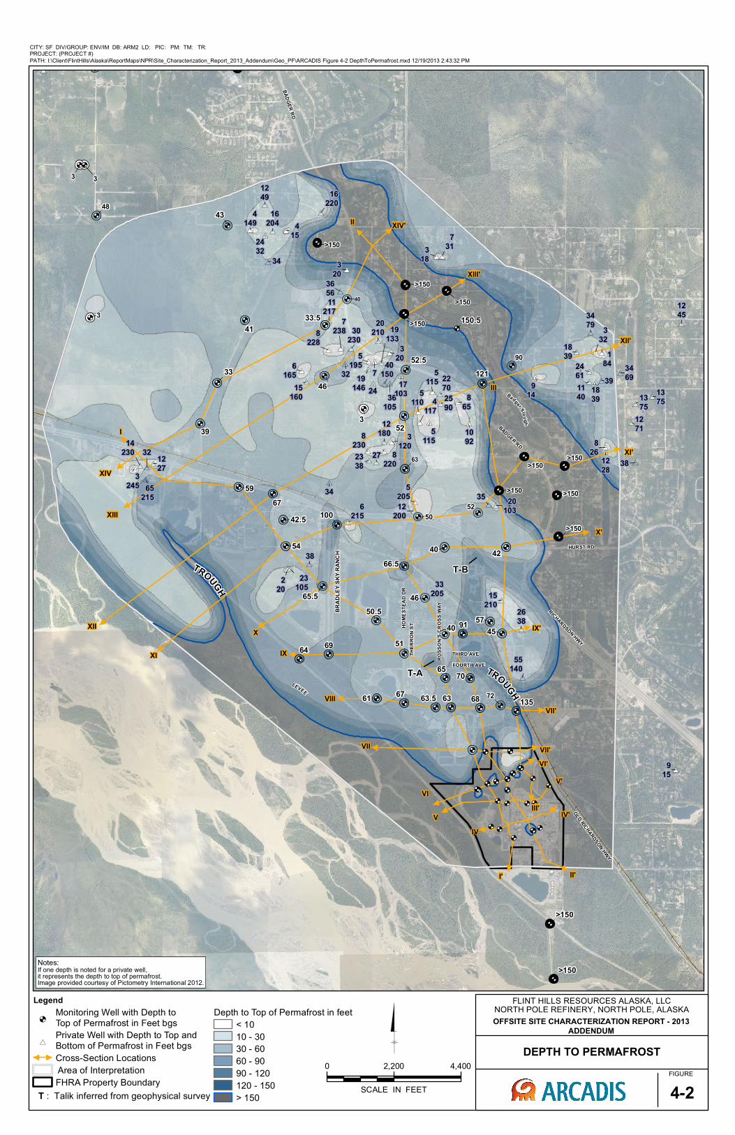
The North Pole area is located in a region of discontinuous permafrost. Permafrost is believed to be absent under the Tanana River and appears to also be absent under the North Pole Refinery, at least to the maximum depth of investigation (150 feet bgs). Permafrost also appears to be thawed under Badger Slough. North of the refinery, depth to permafrost decreases and in some areas, permafrost is encountered near the ground surface. Appendix A includes Figure 4-2 from the Offsite Site Characterization Report – 2013 Addendum (ARCADIS 2013b), which is a map of the depth to permafrost in the sulfolane plume area prepared by Flint Hills Resources (FHR) based on geophysical surveys and monitoring well data.
The thickness of the aquifer varies based on the presence of permafrost. In areas where permafrost is absent, the aquifer is assumed to extend from the water table (which ranged between approximately 7 and 13 feet bgs during 2013 characterization activities [ARCADIS 2013b]) to bedrock. In areas where the permafrost extends to the ground surface, there is no suprapermafrost groundwater. Throughout much of the North Pole area, the suprapermafrost aquifer thickness is somewhere between these two extremes. As shown on Figure 4-2 in Appendix A, the depth to permafrost in the sulfolane plume north of the NPR is generally around 60 to 70 feet bgs.
The groundwater flow direction in the suprapermafrost aquifer generally varies from a north-northwesterly direction to a few degrees east of north. The groundwater flow direction trends to the north-northwest in spring and more northerly in the summer and fall (Glass et al. 1996). Glass et al report a slope on the water table of 4 feet per mile. The 2013 Offsite Site Characterization Report Addendum (ARCADIS 2013b) presented a detailed groundwater flow analysis based on 49 triangular groups of wells containing dataloggers and screened across the water table. The ARCADIS analysis confirms the
North Pole Sulfolane Plume Interim Excavation Dewatering Management Plan ADEC
ERM 10 7/20/2014
general groundwater flow information reported by Glass et al, and also notes some variability of flow direction within the sulfolane plume area. Appendix A includes Figure 5-8 from the Onsite Site Characterization Report-2013 Addendum (ARCADIS 2013a), which is a plot of horizontal flow directions from their analysis. Horizontal gradients were calculated to range between 0.0004 and 0.002 feet/foot.
The water table elevation fluctuates seasonally. The groundwater elevation typically decreases during winter and early spring and begins to increase during spring break-up, reaching a peak in mid-summer, and then decreases again through the rest of the year. The lowest elevations typically occur from late March through May and highest elevations typically peak during late July or August. The seasonal water table fluctuations in three USGS monitoring wells located near the NPR, to the east and southeast, are described in Appendix 5-B to the 2013 Offsite Site Characterization Report Addendum (ARCADIS 2013b). Appendix A includes Figure 4 from the ARCADIS Appendix 5-B, which illustrates the water table fluctuation in the USGS “Site 6” well, located approximately 1/2 mile due east of the NPR. This figure shows a fluctuation between 3 and 4 feet in the period of record (2001 to 2011).
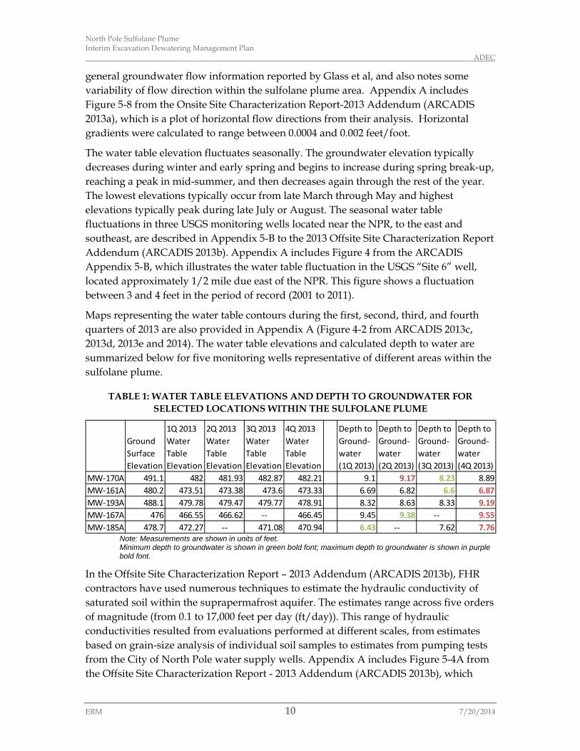
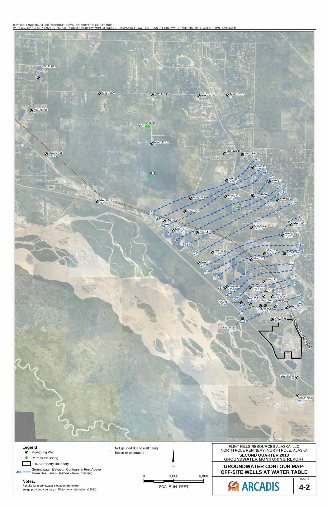
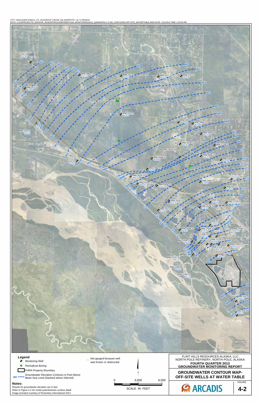
Maps representing the water table contours during the first, second, third, and fourth quarters of 2013 are also provided in Appendix A (Figure 4-2 from ARCADIS 2013c, 2013d, 2013e and 2014). The water table elevations and calculated depth to water are summarized below for five monitoring wells representative of different areas within the sulfolane plume.
TABLE 1: WATER TABLE ELEVATIONS AND DEPTH TO GROUNDWATER FOR SELECTED LOCATIONS WITHIN THE SULFOLANE PLUME
Note: Measurements are shown in units of feet. Minimum depth to groundwater is shown in green bold font; maximum depth to groundwater is shown in purple bold font.
In the Offsite Site Characterization Report – 2013 Addendum (ARCADIS 2013b), FHR contractors have used numerous techniques to estimate the hydraulic conductivity of saturated soil within the suprapermafrost aquifer. The estimates range across five orders of magnitude (from 0.1 to 17,000 feet per day (ft/day)). This range of hydraulic conductivities resulted from evaluations performed at different scales, from estimates based on grain-size analysis of individual soil samples to estimates from pumping tests from the City of North Pole water supply wells. Appendix A includes Figure 5-4A from the Offsite Site Characterization Report - 2013 Addendum (ARCADIS 2013b), which
Ground Surface Elevation
1Q 2013 Water Table Elevation
2Q 2013 Water Table Elevation
3Q 2013 Water Table Elevation
4Q 2013 Water Table Elevation
Depth to Ground-water (1Q 2013)
Depth to Ground-water (2Q 2013)
Depth to Ground-water (3Q 2013)
Depth to Ground-water (4Q 2013)
MW-170A 491.1 482 481.93 482.87 482.21 9.1 9.17 8.23 8.89MW-161A 480.2 473.51 473.38 473.6 473.33 6.69 6.82 6.6 6.87MW-193A 488.1 479.78 479.47 479.77 478.91 8.32 8.63 8.33 9.19MW-167A 476 466.55 466.62 -- 466.45 9.45 9.38 -- 9.55MW-185A 478.7 472.27 -- 471.08 470.94 6.43 -- 7.62 7.76

North Pole Sulfolane Plume Interim Excavation Dewatering Management Plan ADEC
ERM 11 7/20/2014
depicts hydraulic conductivity distribution with depth based on grain-size analysis of individual soil samples. This figure shows that the lowest hydraulic conductivities are limited to the shallowest samples, and most hydraulic conductivities are between 10 ft/day and 100 ft/day.
The hydraulic conductivities most relevant to shallow operations are the conductivities calculated from shallow pumping tests dewatering (although none were conducted at depths less than 20 feet bgs); these are summarized below.
• Estimates based on the single-well pumping tests performed in 2011 ranged from 50 to 10,700 ft/day (second highest was 720 ft/day), with a geometric mean of 270 ft/day. The tests included 14 monitoring wells ranging in depth between 20 feet bgs and 101 feet bgs.
• Estimates based on single-well pumping tests performed in 2012 ranged from 140 to 1,100 ft/day, with a geometric mean of 400 ft/day. The tests were performed on shallow tracer testing wells (screened from 20 to 40 feet bgs).
• Estimates based on single-well pumping tests performed in 2013 ranged from 19 to 54 ft/day with a geometric mean of 33 ft/day for finer-grained soil, and 28 to 455 ft/day with a geometric mean of 100 ft/day for coarser-grained soil. The tests were performed on shallow tracer testing wells (well depths between 27 and 38 feet bgs).
• There have been three pumping tests of the FHR recovery wells. These wells are screened between 24 and 41 feet bgs.
o Estimates based on 2009 testing of the recovery well system ranged from 500 to 2,300 ft/day with a geometric mean of 1,100 ft/day.
o Estimates based on 2011 testing of the recovery well system ranged from 1,000 to 1,500 ft/day, with a geometric mean of 1,300 ft/day.
o Estimates based on 2013 testing of the recovery well system ranged from 300 to 1,600 ft/day. Mean values were calculated for multiple analyses on each of four pumping wells. These mean values ranged between 200 ft/day and 370 ft/day.
Additional aquifer parameters were calculated by FHR based on a summer 2013 pump test of the NPR groundwater recovery wells. Pressure transducers with dataloggers were used to measure the aquifer response in a number of observation wells located at various distances and directions away from the pumping wells. Based on the measured aquifer response, aquifer parameters were calculated using AQTESOLV™ software from the four single well pumping tests. Some of the aquifer parameters are summarized below in Table 2. The report authors noted that the pumping test did not match the standard curves very well and concluded that was due to significant aquifer heterogeneity. The full details of the testing may be found in the report entitled

North Pole Sulfolane Plume Interim Excavation Dewatering Management Plan ADEC
ERM 12 7/20/2014
Evaluation of Recovery Well Replacement, Start-up Aquifer Testing for Recovery System, Hydraulic Capture Performance Monitoring (Barr 2013).
TABLE 2: SUMMARY OF AQUIFER PARAMETERS FROM 2013 PUMPING TEST (BARR 2013)
Note: T=Aquifer transmissivity
Sc=Aquifer Storage Coefficient.
2.2.7.3.2 Using proposed or existing monitoring wells that are capable of providing information on groundwater elevations determine whether contaminants are being smeared below the natural minimum groundwater elevation, whether the contaminant plume is being diverted, and whether contaminant migration rates are increasing; and
2.2.7.3.3 When the dewatering activity may adversely affect a contaminated site by moving or smearing contaminants, the applicant must describe how construction practices such as cofferdams, or other methods will be used to prevent adverse effects upon groundwater quality.
Smearing of contamination below the natural minimum groundwater elevation is only a concern if the contaminant is lighter than water and “floats” on the water surface, as is the case with petroleum hydrocarbons. In the North Pole Sulfolane plume, the sulfolane is dissolved in the groundwater and there is no floating contamination. Therefore, “smearing” contaminants below the natural minimum groundwater elevation is not a concern.
Plume diversion is only a concern for dewatering operations occurring outside of the contaminant plume. In this case, the groundwater pumping can divert the plume towards the dewatering operation. However, impacts to the North Pole sulfolane plume would be expected to be de minimus, because the plume is so extensive that sulfolane concentrations near the plume boundaries are near the analytical reporting limit. The actual mass of sulfolane that would be diverted would be very small, and dilution with clean water pumped from outside the plume would most likely decrease the sulfolane concentration in the dewatering discharge below the analytical reporting limit. However, the ADEC’s Division of Water and Contaminated Sites Program will review any excavation dewatering projects located just outside or along the border of the sulfolane plume for authorization on a case-by-case basis.
For dewatering operations within the sulfolane plume boundaries, plume diversion is not a concern. Pumping groundwater from within the extensive North Pole sulfolane plume may cause insignificant and transient changes in the distribution of sulfolane
WellDepth (ft bgs)
Pumping Rate (gpm)
Drawdown (feet)
Elapsed Time (hrs)
Specific capacity (gpm/ft) T (m2/d) T (ft2/d)
Sc (unitless)
R-42 35 122 2.4 10 50 14,700 158,200 0.01R-43 41 116 23.4 6.5 5 15,100 162,500 0.003R-44 41 125 6.6 10 19 16,700 179,800 0.011R-45 32 70 12.6 8 5.6 9,000 96,900 0.021

North Pole Sulfolane Plume Interim Excavation Dewatering Management Plan ADEC
ERM 13 7/20/2014
within the plume but will not affect the overall plume length, width, or migration. To further ensure that dewatering operations within the plume do not cause plume expansion, dewatering discharge containing sulfolane may not be discharged outside of the plume boundaries.
2.2.7.4 The information described in Part 2.2.7.3 is not required if the applicant can demonstrate that the contaminated site(s) within 1,500 feet of the dewatering activity does not affect the groundwater within the dewatering area of influence. The following activities may be used to demonstrate this:
2.2.7.4.1 Using existing groundwater monitoring wells to generate a groundwater flow map that includes the static water level of all wells, groundwater flow direction, and groundwater elevation contours to demonstrate dewatering activities will not impact the plume; or
2.2.7.4.2 A simulated aquifer pump test conducted with groundwater modeling software or a similar study at the projected maximum dewatering rate to determine, radii of influence, drawdown, and rate of recharge, which verifies pumping will not affect the contaminated plume.
The condition described in 2.2.7.4 is not met for dewatering operations requiring this BMP. Dewatering operations are within the sulfolane plume so by definition the plume affects the dewatering area of influence. Dewatering operations outside of the sulfolane plume boundary but within 1,500 feet are addressed under 2.2.7.3.
2.4. Project Area GIS Map A GIS-based map was developed to help contractors prepare their Excavation Dewatering Permit Application. The map shows the boundary within which applicants are required to file a NOI and BMP Plan (Fairbanks Meridian Township 1S/ Range 2E/ Sections 31, 32, and 33; and Township 2S/ Range 2E/ Sections 4, 5, 6, 7, 8, 9, 16, and 17), groundwater monitoring well locations, surface water body locations, property boundaries, and surface topographical contours. The map may be used by applicants to identify the location of aforementioned components near their project sites. Note however, all components shown on the map shall be field-verified prior to design or application.
The GIS map may be found at the following website location. Please choose the “Alaska DEC North Pole Sulfolane Impacted Area Dewatering Map”.
http://dec.alaska.gov/das/gis/apps.htm

North Pole Sulfolane Plume Interim Excavation Dewatering Management Plan ADEC
ERM 14 7/20/2014
- Page Intentionally Left Blank -

North Pole Sulfolane Plume Interim Excavation Dewatering Management Plan ADEC
ERM 15 7/20/2014
3. EXCAVATION DEWATERING BMP PLAN
This Interim Excavation Dewatering Management Plan addresses the discharge of contaminated sulfolane water to the land surface. The land discharge must not cause sulfolane plume expansion or impact waters of the United States (U.S.). To meet this restriction, the applicant must ensure that the dewatering operation follows BMPs to keep the contaminated water from migrating beyond the plume boundary or entering any conveyance system where the wastewater could join a surface water body. The most likely discharge locations will either be to retain the water onsite (in which case the contaminated water must be kept from migrating off the property) or to discharge to a roadside drainage ditch that is effectively partitioned off from the rest of the North Pole or FNSB MS4 system (in which case the contaminated water must infiltrate into the ground and be kept from migrating into any part of the MS4 system that conveys to surface water). Infiltration of the wastewater discharge back into the groundwater system will be the primary means of excavation dewatering management. In summary, the following conditions would need to be met for a discharge to land in the North Pole sulfolane plume area.
• The discharge is to uplands (within the plume’s boundaries) and not wetlands considered waters of the U.S.;
• The portion of the MS4 receiving the discharge is effectively partitioned (e.g., diked) off from the rest of the MS4, thereby removing it from being a conveyance of wastewater to waters of the U.S. and not subject to the terms and conditions of the MS4 permit; and
• The partitioned area must be sized large enough to accept the volume of excavation dewater as well as soils conducive to allow for complete permeation of the dewatering discharge.
3.1. BMP Plan Requirements Applicants with excavation dewatering projects in the North Pole sulfolane plume area are required to submit a BMP Plan along with their NOI submittal a minimum of 30 days prior to the date the discharge is scheduled to commence. Per the Final - Excavation Dewatering General Permit AKG002000, the BMP Plan must include all of the following elements:
• A description how the wastewater will be managed with a description of each BMP to be implemented. Example BMPs for various infiltration facilities are provided in this interim management plan.
• A description of the land disposal site conditions such as soils, topography, drainage patterns, depth to groundwater, and existing vegetation.
• A detailed site map to scale that shows the discharge points, infiltration areas, drainage boundaries, flow direction of discharged water, location of all waters of

North Pole Sulfolane Plume Interim Excavation Dewatering Management Plan ADEC
ERM 16 7/20/2014
the U.S. on site and those located within 2,500 feet of the site boundary, and location of BMPs to be implemented.
• The BMP Plan shall be signed and certified by the applicant in accordance to the requirements of the Excavation Dewatering General Permit, Appendix A, Part 1.12.
3.2. Water Balance Management Methods Due to the sulfolane contamination of the groundwater in the North Pole area, it is extremely important to carefully evaluate the excavation dewatering water balance and use BMPs to minimize the quantity of water that needs to be dealt with. A list of possible options for reducing the volume of water to be managed is provided below:
• Design Modifications – alterations to the project design that will eliminate or minimize the need for excavation dewatering. Design modifications are the easiest method of managing excavation dewatering in North Pole, as least for the present time.
• Phased Excavation – reduce excavation dewatering by managing to keep the excavation area as small as possible during construction. Phased excavation does have certain limitations such as when construction projects have inspection requirements that require system installations remain open until they pass inspection.
• Temporary storage – temporary storage may be used to keep wastewater discharge rates below or within a specified maximum discharge rate. Temporary storage may also be used to allow for testing of wastewater to determine if the water quality meets required specifications for unrestricted discharge (i.e., allowed to enter waters of the U.S.).
3.3. Estimate of Dewatering Production Rate and Volume After planning the excavation to minimize dewatering volumes in accordance with Section 3.2 and performing any necessary site characterization efforts, the first step in the design of an excavation dewater project is generally to determine the wastewater volume that will be generated during the excavation dewatering. This can be done by several methods including flow net analysis, analytical computations, or groundwater modeling programs. An estimate of the volume is necessary to evaluate the options for managing the discharge.
Once these values have been estimated then a trial analysis of the wastewater discharge system may be performed. At present the only wastewater discharge method available for the North Pole sulfolane plume area is use of some type of infiltration facility.
To perform a trial analysis of an infiltration facility, assume an infiltration rate based on previously available data or using a default infiltration rate of 0.3 inches/hour (WSDOT, 2014) to develop a trial infiltration facility geometry based on length, width, and depth.

North Pole Sulfolane Plume Interim Excavation Dewatering Management Plan ADEC
ERM 17 7/20/2014
Use this trial geometry to help locate the facility and for planning purposes in developing the geotechnical subsurface investigation plan. If the site is not capable of accommodating the geometry requirements, then other alternatives such as permission to use offsite public or private land may be evaluated or attempts to reduce the wastewater discharge requirements may also be considered as discussed in Section 3.2.
3.4. Excavation Dewatering BMPs The three methods used to control water entering an excavation include groundwater control by pumping, groundwater control by exclusion, and surface water control.
3.4.1. Groundwater Control by Pumping
Successful dewatering requires that the techniques used are appropriate to the type of excavation and hydrogeological conditions at the construction site. Dewatering techniques must be selected carefully, as the various techniques are not interchangeable and are only effective within certain conditions. The figure below provides useful initial guidance on the selection of dewatering techniques in relation to the permeability (hydraulic conductivity) of the aquifer and the required drawdown of groundwater levels.
RANGE OF APPLICATION OF EXCAVATION DEWATERING METHODS
(SOURCE: CIRCA C515 GROUNDWATER CONTROL – DESIGN AND PRACTICE)
The most common excavation dewatering methods are well-point systems and gravity drainage to a sump pump. Both methods require thoughtful planning for disposal of the removed water. Discharge from a well-point system is relatively clear while that from sump pumps is thoroughly sediment laden without any treatment. A sediment
North Pole Sulfolane Plume Interim Excavation Dewatering Management Plan ADEC
ERM 18 7/20/2014
intake filter or other sediment pretreatment system is highly recommended for use with any sump pump dewatering system.
3.4.2. Groundwater Control by Exclusion
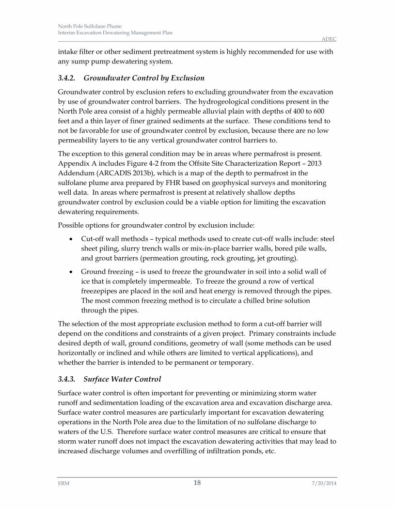
Groundwater control by exclusion refers to excluding groundwater from the excavation by use of groundwater control barriers. The hydrogeological conditions present in the North Pole area consist of a highly permeable alluvial plain with depths of 400 to 600 feet and a thin layer of finer grained sediments at the surface. These conditions tend to not be favorable for use of groundwater control by exclusion, because there are no low permeability layers to tie any vertical groundwater control barriers to.
The exception to this general condition may be in areas where permafrost is present. Appendix A includes Figure 4-2 from the Offsite Site Characterization Report – 2013 Addendum (ARCADIS 2013b), which is a map of the depth to permafrost in the sulfolane plume area prepared by FHR based on geophysical surveys and monitoring well data. In areas where permafrost is present at relatively shallow depths groundwater control by exclusion could be a viable option for limiting the excavation dewatering requirements.
Possible options for groundwater control by exclusion include:
• Cut-off wall methods – typical methods used to create cut-off walls include: steel sheet piling, slurry trench walls or mix-in-place barrier walls, bored pile walls, and grout barriers (permeation grouting, rock grouting, jet grouting).
• Ground freezing – is used to freeze the groundwater in soil into a solid wall of ice that is completely impermeable. To freeze the ground a row of vertical freezepipes are placed in the soil and heat energy is removed through the pipes. The most common freezing method is to circulate a chilled brine solution through the pipes.
The selection of the most appropriate exclusion method to form a cut-off barrier will depend on the conditions and constraints of a given project. Primary constraints include desired depth of wall, ground conditions, geometry of wall (some methods can be used horizontally or inclined and while others are limited to vertical applications), and whether the barrier is intended to be permanent or temporary.
3.4.3. Surface Water Control
Surface water control is often important for preventing or minimizing storm water runoff and sedimentation loading of the excavation area and excavation discharge area. Surface water control measures are particularly important for excavation dewatering operations in the North Pole area due to the limitation of no sulfolane discharge to waters of the U.S. Therefore surface water control measures are critical to ensure that storm water runoff does not impact the excavation dewatering activities that may lead to increased discharge volumes and overfilling of infiltration ponds, etc.

North Pole Sulfolane Plume Interim Excavation Dewatering Management Plan ADEC
ERM 19 7/20/2014
Surface water control measures often include items such as interception/diversion ditch, berm, or excavated channel that function to intercept runoff and divert it around the excavation dewatering and infiltration areas. Please refer to the Alaska Stormwater Pollution Prevention Plan (SWPPP) Guide BMP AK-2 for additional details regarding design and construction of interception/diversion ditches (ADOT, 2011).
3.5. Land Surface Discharge BMPs In accordance with the conditions of Final – General Excavation Dewatering Permit AKG002000, the presence of sulfolane in the North Pole groundwater eliminates the possibility of discharge to waters of the U.S. That leaves infiltration to groundwater as the only reasonable mechanism for wastewater disposal.
A list of possible options for promoting infiltration of wastewater discharges includes the following. Details on each of these BMPs are provided in Appendix B.
• Infiltration Basins – are earthen impoundments used for the collection, temporary storage, and infiltration of incoming wastewater to groundwater. They effectively control pollutants in wastewater discharge by preventing surface runoff, but are not intended for control of sediment because of potential for clogging.
• Infiltration Trenches – are long, narrow, stone-filled trenches used for the collection, temporary storage, and infiltration of wastewater to groundwater. They can be a useful alternative for sites with constraints that make siting an infiltration basin difficult. For instance infiltration trenches may be suitable for use in or adjacent to a drainage ditch along a road right-of-way.
• Land Application by Dispersal – wastewater discharge to vegetated land for infiltration. This includes land application dispersal systems (i.e., perforated piping or sprinkler heads) that spread the wastewater discharge over a larger area to improve the infiltration capacity of the system.
• Check Dams – are primarily used to reduce scour and channel erosion by reducing flow velocity and encouraging sediment settling. However, they can also be used to promote additional infiltration through the creation of small ponds of water along a flow channel.
It is anticipated that a roadside drainage ditch located in the City or Borough public right of way is a likely discharge location. These roadside drainage ditches are classified as part of the North Pole of FNSB MS4 system. Depending on the site-specific details, discharge to a roadside drainage ditch could be managed using one of the four BMPs presented in Appendix B, and listed above, to ensure that the sulfolane-contaminated discharge does not migrate into any part of the MS4 system that conveys to surface water.

North Pole Sulfolane Plume Interim Excavation Dewatering Management Plan ADEC
ERM 20 7/20/2014
- Page Intentionally Left Blank -
North Pole Sulfolane Plume Interim Excavation Dewatering Management Plan ADEC
ERM 21 7/20/2014
4. REFERENCES
Alaska Department of Transportation and Public Facilities (ADOT) 2011 Alaska Storm Water Pollution Prevention Plan Guide. February 2011.
ARCADIS 2013a Flint Hills Resources Alaska, LLC. Onsite Site Characterization Report –2013 Addendum, Flint Hills Refinery, North Pole, Alaska. December 20, 2013.
ARCADIS 2013b Flint Hills Resources Alaska, LLC. Offsite Site Characterization Report –2013 Addendum, Flint Hills Refinery, North Pole, Alaska. December 20, 2013.
ARCADIS 2013c Flint Hills Resources Alaska, LLC. First Quarter 2013 Groundwater Monitoring Report, Flint Hills Refinery, North Pole, Alaska. DEC File Number: 100.38.090. May 31, 2013.
ARCADIS 2013d Flint Hills Resources Alaska, LLC. Second Quarter 2013 Groundwater Monitoring Report, Flint Hills Refinery, North Pole, Alaska. DEC File Number: 100.38.090. July 31, 2013.
ARCADIS 2013e Flint Hills Resources Alaska, LLC. Third Quarter 2013 Groundwater Monitoring Report, Flint Hills Refinery, North Pole, Alaska. DEC File Number: 100.38.090. October 31, 2013.
ARCADIS 2014 Flint Hills Resources Alaska, LLC. Fourth Quarter 2013 Groundwater Monitoring Report, Flint Hills Refinery, North Pole, Alaska. DEC File Number: 100.38.090. January 31, 2014.
Barr 2012 Site Characterization Report –Through 2011, North Pole Refinery, North Pole, Alaska. DEC File Number: 100.38.090, Prepared for Flint Hills Resources Alaska, LLC. December 2012.
Barr 2013 Evaluation of Recovery Well Replacement, Start-up Aquifer Testing for Recovery System, Hydraulic Capture Performance Monitoring, Flint Hills Resources Alaska, LLC, North Pole Refinery, Prepared for Flint Hills Resources Alaska, LLC, August 2013.
Glass, R.L., M.R. Lilly, and D.F. Meyer. 1996. Ground-water levels in an alluvial plain between the Tanana and Chena Rivers near Fairbanks, Alaska, 1986-93: U.S. Geological Survey Water-Resources Investigations Report 96-4060.
Preene et.al. 2000. CIRCA Report C515 Groundwater Control – Design and Practice.
Washington State Department of Transportation (WSDOT). 2014. Highway Runoff Manual. M 31-16.04.

North Pole Sulfolane Plume Interim Excavation Dewatering Management Plan ADEC
ERM 22 7/20/2014
- Page Intentionally Left Blank -

APPENDIX A
North Pole Sulfolane Plume and Hydrogeology Figures

- Page Intentionally Left Blank -

MW-322-15<6.32
MW-322-150<6.32
MW-326-20<5.50
MW-326-150<5.80
MW-343-15<6.32
MW-335-41- -
MW-189A-15- -MW-189B-60- -
MW-182A-15- -
MW-308-30- -
MW-172A-15- -
MW-172B-150- -
MW-148A-1532.8
MW-150A-1049.8
MW-151A-1557.0
MW-152A-1570.0
MW-153A-1537.0
MW-155A-1511.3
MW-156A-1536.6
MW-157A-1566.5
MW-158A-1570.3
MW-159A-1513.2
MW-160AR-15<6.20
MW-161A-15137 MW-162A-15
28.8
MW-163A-1533.6
MW-164A-1568.3
MW-165A-15<6.32
MW-166A-1534.1
MW-167A-153.97J
MW-168A-1514.3
MW-169A-15<6.32
MW-170A-15<6.20
MW-171A-15<6.36
MW-181A-15<6.20
MW-183A-1575.2
MW-185A-15<6.20
MW-187-154.54J
MW-190A-15<6.20
MW-191A-15<6.20
MW-193A-15<6.40
MW-194A-1538.3
MW-308-159.86J
MW-311-15<6.20
MW-314-15<6.20
MW-316-153.38J
MW-317-154.84J
MW-318-20<6.20
MW-323-15<6.46
MW-325-18<6.36
MW-328-15<6.20
MW-329-1575.3
MW-332-15<6.20
MW-338-1531.2
MW-339-1544.2
MW-340-18<6.32
MW-341-1596.7
MW-342-15100
MW-349-1555.0
MW-148B-30112
MW-148C-5563.8
MW-150B-2541.0
MW-150C-6012.7
MW-151B-2534.4
MW-151C-6021.3
MW-152B-2571.2
MW-152C-6521.7
MW-153B-5524.5
MW-155B-65<6.20
MW-156B-5025.1
MW-157B-3074.0
MW-158B-6068.1
MW-159B-4561.8
MW-161-30170
MW-161B-50230 MW-162B-65
63.9
MW-163B-4025.6
MW-164B-5085.2MW-164C-6083.7
MW-165B-50<6.46
MW-166B-3061.6
MW-167B-3512.3
MW-168B-5019.5
MW-169C-60<6.20
MW-170D-50<6.20
MW-171B-40<6.40
MW-181B-50<6.20
MW-182B-4523.3
MW-183B-60129
MW-184-45<6.32
MW-185B-506.69J
MW-190BR-60<6.20
MW-191B-60<6.40
MW-193B-60<6.32
MW-194B-4059.1
MW-311-46<6.32
MW-316-56<6.20
MW-323-50<6.46
MW-329-6689.8
MW-332-41<6.20
MW-338-5046.0
MW-339-5039.5
MW-340-65<6.20
MW-341-4087.1
MW-342-65169
MW-343-50<6.20
MW-349-4556.8
MW-159C-7051.9
MW-160B-9062.9
MW-170B-75<6.36
MW-317-718.99J
MW-332-75<6.20
MW-148D-150<6.20
MW-170C-130<6.32
MW-181C-150<6.20
MW-185C-1203.57J
MW-190-150<6.20
MW-314-150<6.20
MW-318-135<6.32
MW-325-150<6.36
MW-328-151<6.20
MW-332-11025.7
MW-332-150230
MW-340-150<6.46
MW-356-15<6.20
MW-357-15<6.74
MW-356-65<6.66
MW-357-65<6.74
MW-148-100<6.66
MW-148-8013.6
MW-356-90<6.88
MW-357-150<6.66
MW-346-157.19J
MW-346-150<6.20
MW-346-6522.7
MW-347-1509.57J
MW-347-6527.4
MW-347-2012.9
MW-350-5047.7
MW-350-1530.3
MW-352-155.10J
MW-352-408.73J
MW-353-100198
MW-353-65204
MW-353-15157
OLD RICHARDSON HIGHWAY
PF-2PF-1
PF-3
PF-4
CITY: HIGHLANDS RANCH, CO DIV/GROUP: ENV/IM DB: BGRIFFITH LD: G FRANCE PATH: W:\GISPRJ\GISPROJECTS\_ENV\FHR_AK\NORTHPOLEREFINERY\GW_MONITORING\2013_Q4\MXD\FIG 4-25 OFFSITEGWANALYTICALRESULTS_SUPRAPERMAFROST.MXD DATE: 1/30/2014 TIME: 3:13:27 PM
0 2,500 5,000
SCALE IN FEET
FLINT HILLS RESOURCES ALASKA, LLCNORTH POLE REFINERY, NORTH POLE, ALASKA
GROUNDWATER ANALYTICAL RESULTS FROM OFFSITE MONITORING WELLS AND PRIVATE WELLS SCREENED
IN THE SUPRAPERMAFROST AQUIFERFIGURE
4-25
FOURTH QUARTER 2013GROUNDWATER MONITORING REPORT
LegendMonitoring Well
Private Well
Point-of-entry treatment system sample collected
Permafrost at Surface (no shallow groundwater present)
Initial Result from Fourth Quarter 2013
Approximate Sulfolane Isopleth in µg/L
Suprapermafrost and Subpermafrost mixing zone
FHRA Property Boundary
Private Well Sulfolane ResultsNot Detected3.1 - 100 µg/L100 - 1,000 µg/L> 1,000 µg/L
Monitoring Well Sulfolane ResultsNot Detected3.1 - 100 µg/L100 - 1,000 µg/L> 1,000 µg/L
Notes:-Monitoring wells installed to all depths and private wells installed to a depth of 40 feet bgs or shallower are shown on this figure-Contours are generally based on fourth quarter 2013 results. Contours include some historical data where a fourth quarter 2013 sample had not been collected-For private wells, analytical result is not displayed. Refer to legend for color coding indicating concentration range from most recent sampling event within the last 12 months< = Not detected; Detection limit is listedND = Not DetectedJ = Estimated concentration, detected above the detection limit (DL) and below the limit of quantitation (LOQ)- - Not sampled due to well being frozen or obstructedImage provided courtesy of Pictometry International 2012
#*#*
#*
#*
#*#*
#*
#*
#*
#*#*
#*#*#*#*#*#*
#*
#*
#*#*#* #*#*
#*
#*
#* #*
#*
#*
#*
#* #*
#*
#*#*#*
#*
#*#*#*
#*
#*
#*
#*
#*
#*
#*
#*
#*
#*#*
#*
#*#*#*
#*
#*
#*#*
#*
#*
#*#*#*
#*
#*
#*
#*
#*
#*
#*
#*
#*
#*#*#*
#*
#*
#*
#*
#*
#*
#*
#*
!<
!<
!<
!<
!<
!<
!<
!<
!<
!<
!<
!<
!<
!<
!<
!<
!<
!<
!<
!<
!<
!<
!<
!<
!<
!<
!<
!<
!<
!<
!<
!<
!<
!<
!<
!<
!<
!<
!<
!<
!<
!<
!<
!<
!<!<
!<
!<
!<
!<!<
!<
!<
!<
!<
!<
!<
!<
!<
!<!<!<!<!<
!<!<!<!<!<
!<
!<
!<
!<
!<
!<
!< !<
!<
!<
!<
!<
!<
!<
!<
!<
!<
!<
!<
!<
!<
!< !<
!<
!<
!<
!<
!<
!<
!<
!<
!<!<
!<
!<
!<
!<
!<
!<
!<
!<
!<
!<!<
!<
!<
!<
!<
!<
!<
!<
!<
!<
!<!<
!<
!<
!<
!< !<
!<
!<
!<
!<
!<
!<
!<
!<
!<
!<
!<
!<
!<
!<
!<
!<
BADGER RD
HOME
STEA
D DR
OLD RICHARDSON HWY
HURST RD
BADGER RD
RICHARDSON HWY
II XIV'
XIII'
XII'
III
I
XIV
XIII
XII
XI
X
IX
XI'
X'
IX'
VII'VIII
VII VII'
VI
VI'
VIV
IV'
II'I'
Badger Slough
T-BTROUGH
LEVEE
TROUGH
T-A
3 3
48
3
III'
V'
>150
>150
>150
>150
90
>150>150
>150>150
52
40
>15050
72
BRAD
LEY S
KY R
ANCH
FOURTH AVETHIRD AVETH
ERRO
N ST
ROSS
ON'S
CROS
S WA
Y
63.5 63 6867
5140
65 70
91
5466.5
40
63
33
33.5
52.5
69
135
42
150.5
46
59
45
121
61
39
41
57
64
67
43
50.5
52
42.5
65.5 46
100
3
>150
>150
7313
18
5110
16220
3479
38
2590
3120
5115
4117
184
332
18393
20
30230
7238
38
34
114036
105
40150
1839
24
3534
39
33205
20210
2461 34
69
2432
19133
75
195
55140
1375
2270
5115
65215
11217
32
12180
1249
82632
914
8220
8230
415
16204
4149
15160
15210
19146
6165
8228
1271
272338 12
28
915
1375
5205
2638
320
3656
20103
14230
3245
1227
17103
220
12200
6215
1245
865
1092
23105
CITY: SF DIV/GROUP: ENV/IM DB: ARM2 LD: PIC: PM: TM: TR: PROJECT: (PROJECT #)
0 2,200 4,400
SCALE IN FEET
PATH: I:\Client\FlintHills\Alaska\ReportMaps\NPR\Site_Characterization_Report_2013_Addendum\Geo_PF\ARCADIS Figure 4-2 DepthToPermafrost.mxd 12/19/2013 2:43:32 PM
FLINT HILLS RESOURCES ALASKA, LLCNORTH POLE REFINERY, NORTH POLE, ALASKA
DEPTH TO PERMAFROSTFIGURE
4-2
OFFSITE SITE CHARACTERIZATION REPORT - 2013 ADDENDUM
Notes:If one depth is noted for a private well,it represents the depth to top of permafrost.Image provided courtesy of Pictometry International 2012.
Legend!<
Monitoring Well with Depth to Top of Permafrost in Feet bgs
*Private Well with Depth to Top andBottom of Permafrost in Feet bgsCross-Section Locations Area of InterpretationFHRA Property Boundary
Depth to Top of Permafrost in feet< 1010 - 3030 - 6060 - 90 90 - 120120 - 150> 150T : Talik inferred from geophysical survey

Tanana River
O-12S-43
MW-187
MW-109
MW-181A
MW-172AMW-167A
MW-166A MW-185AMW-168A
MW-190A
MW-191A
MW-194A
MW-182A
MW-171A
MW-169A
MW-179A
MW-164A
MW-162A
MW-161A
MW-158A
MW-156A
MW-170A
MW-157A
MW-151A
MW-328-15
MW-322-15
MW-325-18
MW-318-20
MW-306-15MW-304-15
MW-310-15
MW-333-16
MW-113
MW-309-15
MW-174-15ND
ND
CITY: SF DIV/GROUP: ENV/IM DB: BGRIFFITH LD: PIC: PM: TM: TR: PROJECT: (PROJECT #)
0 2,100 4,200
SCALE IN FEET
PATH: W:\GISPrj\GISPROJECTS\_ENV\FHR_AK\NorthPoleRefinery\SiteCharacterization2013\2013 Addendum\OFFSITE\Fig 5-8 AverageGWFlowDirections.mxd 12/19/2013 5:37:43 PM
FLINT HILLS RESOURCES ALASKA, LLCNORTH POLE REFINERY, NORTH POLE, ALASKA
AVERAGE GROUNDWATER FLOW DIRECTIONSFIGURE
5-8
OFFSITE SITE CHARACTERIZATIONREPORT - 2013 ADDENDUM
Notes: Image provided courtesy of Pictometry International 2012
LegendMonitoring WellObservation Well
Groundwater Flow Direction
Suprapermafrost SulfolanePlume Isopleths in µg/LFHRA Property Boundary
Depth to Top of Permafrost in feet< 1010 - 3030 - 6060 - 90 90 - 120120 - 150> 150

20
Figure 4
Hydrograph for Site 6 throughout the Period of Record and a Classified Scatter Plot of the Water Level by day of year. Data collection ceased at this well after 2011.

MW-150A480.68
MW-151A482.03
MW-152A481.98
MW-153A483.59
MW-155A481.24
MW-156A479.51
MW-157A478.23
MW-158A480.82 MW-159A
480.90
MW-161A473.51
MW-162A476.09
MW-163A475.91
MW-164A473.00MW-165A
468.76
MW-166AX
MW-167A466.55
MW-168A469.96
MW-169A477.31
MW-170A482.00
MW-171A475.70
MW-172A470.18
MW-181A467.20
MW-182A469.65
MW-183A- -
MW-185A472.27
MW-187X
MW-188A- -
MW-189A- -
MW-190A474.18
MW-191A470.23
MW-193A479.78
MW-194AX
MW-311-15461.40
MW-312-15458.32
MW-313-15- -
MW-315-15452.34
MW-318-20482.10
MW-319-15449.60
MW-322-15462.11
MW-324-15455.46
MW-326-20X
MW-327-15461.27
MW-328-15465.26
MW-332-15474.08
MW-333-16X
450
480
451
479
481482
478477
452
476
453
454
475
455
457
472
456
474473
468469
471
458
467466
459
465
460
464
461
463
462
480
451
479
481
478
477476
453
454
475
455
457
472
456
474
473
468469
471
458
470
467466
459
465
460
464
461
463462
OLD RICHARDSON HIGHWAY
PF-2PF-1
PF-3
PF-4
CITY: HIGHLANDS RANCH, CO DIV/GROUP: ENV/IM DB: BGRIFFITH LD: G FRANCE PATH: W:\ARCGISDATA\GISPROJECTS\_ENV\FHR_AK\NORTHPOLEREFINERY\GW_MONITORING\2013_Q1\MXD\FIG 4-2 GW_CONTOURS-OFF-SITE_WATERTABLE.MXD DATE: 5/17/2013 TIME: 8:56:10 AM
0 3,000 6,000
SCALE IN FEET
FLINT HILLS RESOURCES ALASKA, LLCNORTH POLE REFINERY, NORTH POLE, ALASKA
GROUNDWATER CONTOUR MAP-OFF-SITE WELLS AT WATER TABLE
FIGURE
4-2
FIRST QUARTER 2013GROUNDWATER MONITORING REPORT
LegendMonitoring Well
Permafrost Boring
FHRA Property Boundary
Groundwater Elevation Contours in Feet AboveMean Sea Level (Dashed where Inferred)
Notes:Results for groundwater elevation are in feet Image provided courtesy of Pictometry International 2012
482
--X
Well Frozen or ObstructedNot gauged due to weather
MW-150A--
MW-151A481.78
MW-152A--
MW-153A482.79
MW-155A480.94
MW-156A479.28
MW-157A--
MW-158A-- MW-159A
480.74
MW-161A473.38
MW-162A--
MW-163A475.86
MW-164A473.46
MW-165A--
MW-166A--
MW-167A466.62
MW-168A--
MW-169A477.02
MW-170A481.93
MW-171A476.24
MW-172A--
MW-181A--
MW-182A469.44
MW-183A--
MW-185A--
MW-187--
MW-188A--
MW-189A--
MW-190A474.54
MW-191A469.96
MW-193A479.47
MW-194A--
MW-311-15--
MW-312-15--
MW-313-15--
MW-315-15--
MW-318-20481.79
MW-319-15--
MW-322-15462
MW-324-15454.97
MW-326-20490.52
MW-327-15--
MW-328-15--
MW-332-15474.01
MW-333-16488
480
482481
479478
477
476475
472
473
474
468469
470
471
467
480
482481
479478477
476475
472
473
474
468469
470
471
467
OLD RICHARDSON HIGHWAY
PF-2PF-1
PF-3
PF-4
CITY: HIGHLANDS RANCH, CO DIV/GROUP: ENV/IM DB: BGRIFFITH LD: G FRANCE PATH: W:\GISPROJECTS\_ENV\FHR_AK\NORTHPOLEREFINERY\GW_MONITORING\2013_Q2\MXD\FIG 4-2 GW_CONTOURS-OFF-SITE_WATERTABLE.MXD DATE: 7/18/2013 TIME: 12:06:26 PM
0 3,000 6,000
SCALE IN FEET
FLINT HILLS RESOURCES ALASKA, LLCNORTH POLE REFINERY, NORTH POLE, ALASKA
GROUNDWATER CONTOUR MAP-OFF-SITE WELLS AT WATER TABLE
FIGURE
4-2
SECOND QUARTER 2013GROUNDWATER MONITORING REPORT
LegendMonitoring Well
Permafrost Boring
FHRA Property Boundary
Groundwater Elevation Contours in Feet AboveMean Sea Level (Dashed where Inferred)
Notes:Results for groundwater elevation are in feet Image provided courtesy of Pictometry International 2012
482
- - Not gauged due to well being frozen or obstructed

MW-150A-10482.49MW-151A-15--
MW-152A-15482.89MW-153A-15484.55
MW-155A-15481.70
MW-156A-15480.11
MW-157A-15478.91
MW-158A-15481.72 MW-159A-15481.72
MW-161A-15473.60MW-162A-15--
MW-163A-15476.47
MW-164A-15473.39
MW-165A-15470.12
MW-166A-15--
MW-167A-15--
MW-168A-15--
MW-169A-15--
MW-170A-15482.87
MW-171A-15476.18
MW-172A-15--
MW-181A-15466.89
MW-182A-15--
MW-183A-15―
MW-185A-15471.08
MW-187-15474.05
MW-188A-15456.98
MW-189A-15--
MW-190A-15473.65MW-191A-15471.36
MW-193A-15479.77
MW-194A-15468.80
MW-311-15462.48
MW-312-15-- MW-313-15461.50
MW-315-15453.47
MW-318-20--
MW-319-15451.45
MW-322-15464.90
MW-324-15457.10
MW-326-20493.51
MW-327-15460.81
MW-328-15465.01
MW-332-15474.25
MW-333-16490.36
484
452
482
454
480
456
478
476
458
474
470
472
468
466
460
464
462
484
452
482
454
480
456
478
476
458
474
470
472
468466
460
464462
OLD RICHARDSON HIGHWAY
PF-2PF-1
PF-3
PF-4
CITY: HIGHLANDS RANCH, CO DIV/GROUP: ENV/IM DB: BGRIFFITH LD: G FRANCE PATH: W:\GISPRJ\GISPROJECTS\_ENV\FHR_AK\NORTHPOLEREFINERY\GW_MONITORING\2013_Q3\MXD\FIG 4-2 GW_CONTOURS-OFF-SITE_WATERTABLE.MXD DATE: 10/17/2013 TIME: 5:09:31 PM
0 3,000 6,000
SCALE IN FEET
FLINT HILLS RESOURCES ALASKA, LLCNORTH POLE REFINERY, NORTH POLE, ALASKA
GROUNDWATER CONTOUR MAP-OFF-SITE WELLS AT WATER TABLE
FIGURE
4-2
THIRD QUARTER 2013GROUNDWATER MONITORING REPORT
LegendMonitoring Well
Permafrost Boring
FHRA Property Boundary
Groundwater Elevation Contours in Feet AboveMean Sea Level (Dashed where Inferred)
Notes:Results for groundwater elevation are in feet Image provided courtesy of Pictometry International 2012
482
- - Not gauged because well was frozen or obstructed
!< !< !<
!<
!<
!<
!<
!< !<
!<
!<
!<
!<
!<
!<
!<
!<
!<
!<
!<
!<
!<
!<
!<
!<
!<
!<
!<
!<
!<
!<
!<
!<
!< !<
!<
!<
!<
!<
!<
!<
!<
!<
!<
!<
GFGF
GF
GF
MW-150A-10481.56
MW-151A-15481.95
MW-152A-15482.10
MW-153A-15482.97MW-155A-15
480.78
MW-156A-15479.78
MW-157A-15478.81
MW-158A-15481.27
MW-159A-15481.20
MW-161A-15473.33
MW-162A-15476.35
MW-163A-15476.23
MW-164A-15473.18
MW-165A-15468.74
MW-166A-15466.48
MW-167A-15466.45
MW-168A-15469.32
MW-169A-15476.62
MW-170A-15482.21
MW-171A-15476.15
MW-172A-15- -
MW-181A-15466.72
MW-182A-15- -
MW-183A-15471.31
MW-185A-15470.94
MW-187-15472.89
MW-188A-15457.71
MW-189A-15465.48
MW-190A-15473.75
MW-191A-15469.95
MW-193A-15478.91
MW-194A-15466.47
MW-311-15463.18
MW-312-15459.19
MW-313-15461.38
MW-315-15453.48
MW-318-20481.45
MW-319-15451.82
MW-322-15462.69
MW-324-15456.56
MW-326-20490.22
MW-327-15460.70
MW-328-15464.85
MW-332-15474.14
MW-333-16488.22
490
489
488
487
483
452
482
453
481
454
480
455
479
478
456457
477
476
475
458
474
473472
459
471
470
469468
467
465
466
464
460
463
462
461
490489
488487
483
452
482
453
481
454
480
455
479478
45645
7
477
476
475
458
47447
3
472
459
471470469
468467
465466
464
460
463
462
461
OLD RICHARDSON HIGHWAY
PF-2PF-1
PF-3
PF-4
CITY: HIGHLANDS RANCH, CO DIV/GROUP: ENV/IM DB: BGRIFFITH LD: G FRANCE PATH: Z:\GISPROJECTS\_ENV\FHR_AK\NORTHPOLEREFINERY\GW_MONITORING\2013_Q4\MXD\FIG 4-2 GW_CONTOURS-OFF-SITE_WATERTABLE.MXD DATE: 1/21/2014 TIME: 2:25:53 PM
0 3,000 6,000
SCALE IN FEET
FLINT HILLS RESOURCES ALASKA, LLCNORTH POLE REFINERY, NORTH POLE, ALASKA
GROUNDWATER CONTOUR MAP-OFF-SITE WELLS AT WATER TABLE
FIGURE
4-2
FOURTH QUARTER 2013GROUNDWATER MONITORING REPORT
Legend!< Monitoring Well
GF Permafrost Boring
FHRA Property Boundary
Groundwater Elevation Contours in Feet AboveMean Sea Level (Dashed where Inferred)
Notes:Results for groundwater elevation are in feet Refer to Figure 4-1 for onsite potentiometric surface detailImage provided courtesy of Pictometry International 2012
482
- - Not gauged because well was frozen or obstructed
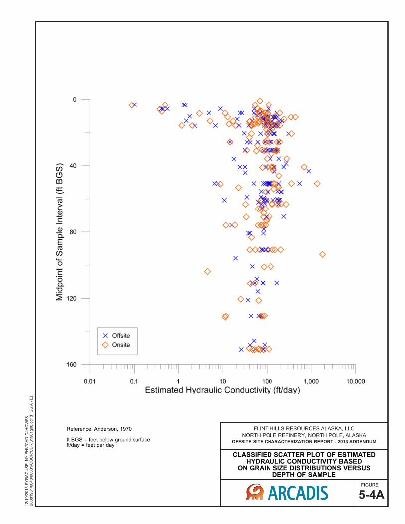
FIGURE
5-4A
12/1
0/2
013 S
YR
AC
US
E, N
Y-E
NV
/CA
D-D
JHO
WE
SB
0081981/0
04
8/0
0001/O
SC
R/C
DR
/81981g08.c
dr
(FIG
S A
- E
)
FLINT HILLS RESOURCES ALASKA, LLC
NORTH POLE REFINERY, NORTH POLE, ALASKAOFFSITE SITE CHARACTERIZATION REPORT - 2013 ADDENDUM
CLASSIFIED SCATTER PLOT OF ESTIMATED HYDRAULIC CONDUCTIVITY BASED
ON GRAIN SIZE DISTRIBUTIONS VERSUSDEPTH OF SAMPLE
Reference: Anderson, 1970
ft BGS = feet below ground surfaceft/day = feet per day

APPENDIX B
Land Surface Discharge Best Management Practices (BMPs)

- Page Intentionally Left Blank -

ERM 1 7/20/2014
APPENDIX B
LAND DISCHARGE BEST MANAGEMENT PRACTICES

ERM 2 7/20/2014
- Page Intentionally Left Blank -

ERM 1 7/20/2014
This Appendix provides BMPs for land discharge of excavation dewatering. BMPs for four different land discharge options are presented. All of these options rely on infiltration of the dewatering discharge back into the groundwater as the mechanism of water management. The four discharge options include the following:
1. Infiltration Basin;
2. Infiltration Trench;
3. Land Application Dispersal; and
4. Check Dam.
BMP selection for any given dewatering operation will depend on the characteristics of the dewatering location (e.g., topography, soil type, size of property) as well as the volume of water requiring management. In general, the largest dewatering operations are more likely to require the more highly-engineered options such as infiltration trench or infiltration basin, while the simpler options, such as land application dispersal, may be more appropriate for smaller dewatering operations.
As discussed in Section 3 of the Excavation Dewatering Management Plan, it is anticipated that a roadside drainage ditch located in the City or Borough public right of way is a likely discharge location. These roadside drainage ditches are classified as part of the North Pole, Fairbanks North Star Borough (FNSB) Municipal Separate Storm Sewer System (MS4). In the case of discharge to a roadside drainage ditch, it is emphasized that the contaminated water must infiltrate into the ground before migrating beyond the sulfolane plume boundaries. The sulfolane-contaminated discharge may not migrate into any part of the MS4 system that conveys to surface water body. Depending on the site-specific details, discharge to a roadside drainage ditch could be managed using one of the four BMPs presented in this Appendix. For example, if the drainage ditch has a sufficient native infiltration rate, it could be used for land discharge by dispersal. Alternatively, if the infiltration rate is not sufficient to manage the discharge without any engineering controls, berms, check dams, or natural land contours could be used to temporarily pond the water to keep it from migrating to any part of the MS4 system that conveys to surface water, provided that adequate storage and handling is provided for stormwater runoff, and flooding of property is not an issue. Alternatively infiltration trenches could also be used to increase the infiltration rate if a layer of low permeability soil is present.

ERM 2 7/20/2014
- Page Intentionally Left Blank -

ERM 3 7/20/2014
B-1. INFILTRATION BASIN
INFILTRATION BASIN
(Source: New Jersey Stormwater BMP Manual, 2004)
B-1.1. Purpose and Application Infiltration basins for flow control are earthen impoundments used for the collection, temporary storage, and infiltration of incoming wastewater to groundwater. For sulfolane contaminated wastewater, infiltration is the preferred and currently only acceptable means of flow control.
For the North Pole area infiltration basins have the advantage over surface applied methods that the finer grained (lower permeability) surface soils would likely be removed allowing for increased infiltration rates. Infiltration basins effectively control pollutants in wastewater discharge by preventing surface runoff, but are not intended for control of sediment because of potential for clogging.
B-1.2. Planning and Design Considerations or General Requirements Infiltration basins should follow a pretreatment process to prevent sediment buildup and clogging of the infiltrative soils. A pre-settling cell can be included in the infiltration basin design.
Infiltration basins require permeable soil conditions for proper function. For a site to be considered suitable for an infiltration basin, the design infiltration rate must be as least 0.5 inches per hour.

ERM 4 7/20/2014
Additional measures may be required for use with infiltration basins to ensure that wastewater discharges do not escape and enter surface water bodies (waters of the U.S.).
B-1.2.1. Site Characterization
One of the first steps in siting and designing infiltration facilities is to conduct a site characterization study.
B-1.2.1.1. Surface Feature Characterization
The surface feature characterization should include the following components.
• Surface topography within 500 feet of the proposed facility.
• Location of water supply wells within 500 feet of proposed facility.
• A description of local site geology, including soil type and permeability, and groundwater regime and flow patterns.
• Location of the infiltration basin relative to groundwater sulfolane plume boundary.
The GIS system described in Section 2.4 provides some of the information needed for the characterization, although field verification is recommended.
B-1.2.1.2. Subsurface Characterization
A minimum of three groundwater monitoring wells are generally required to locate the groundwater table and establish its gradient, direction of flow, and seasonal variations. An estimate of horizontal hydraulic conductivity of the saturated zone is needed to assess the aquifer’s ability to laterally transport the infiltrated water.
Substantial conductivity/permeability data exists for the North Pole area as a result of characterization work performed on the Flint Hills Refinery sulfolane release. This data can be used for infiltration basin siting considerations and for preliminary water balance calculations. A summary of this data is provided in Section 2.3 of this Management Plan.
Note that additional test holes are also needed for determination of the soil permeability as discussed in Section B-1.2.2.
B-1.2.1.3. Soil Testing
Soil characterization for each soil unit (soils of the same texture, color, density, compaction, consolidation, and permeability) encountered should include:
• Grain-size distribution (ASTM D422 or equivalent). • Textural class (USDA) • Percent clay content (include type of clay, if known) • Color/mottling

ERM 5 7/20/2014
• Variations and nature of stratification • Cation exchange capacity (CEC) and organic matter content for each soil type
and strata. (OPTIONAL)
B-1.2.2. Site Soil Permeability
Underlying soil should have a permeability of 0.5 inches per hour or higher. If necessary lower permeability materials may need to be removed to have adequate infiltration rates. Note that permeability, also called “hydraulic conductivity”, as opposed to infiltration rate, should be used to define the rate at which water can seep into the bottom and out of an infiltration trench. Infiltration rate is the actual calculated rate of water decline within the infiltration trench or structure. Surface soil permeability rates are available on the Natural Resource Conservation Service (NRSC) Soil Survey Information website at: http://www.ak.nrcs.usda.gov/soils/index.html or http://websoilsurvey.nrcs.usda.gov/app/HomePage.htm for general soil information of your project area. A geologic investigation of the site, however, is always the preferable method of obtaining a permeability value. Several methods of measuring soil permeability have been developed. The most commonly used method is the falling head percolation test. This method is described in detail in:
• Onsite Wastewater Treatment and Disposal System Design Manual. 1980. EPA, pp 39-49.
A minimum of two percolation test locations should be selected that are within the actual location of the proposed infiltration basin to identify localized soil conditions. For larger infiltration basins, ensure that at least one test pit or test hole per 5,000 ft2 of basin infiltration bottom surface area. Where feasible, larger-scale measurements of permeability are encouraged, using a procedure such as the Pilot Infiltration Test described in the State of Washington’s Stormwater Management Manual.
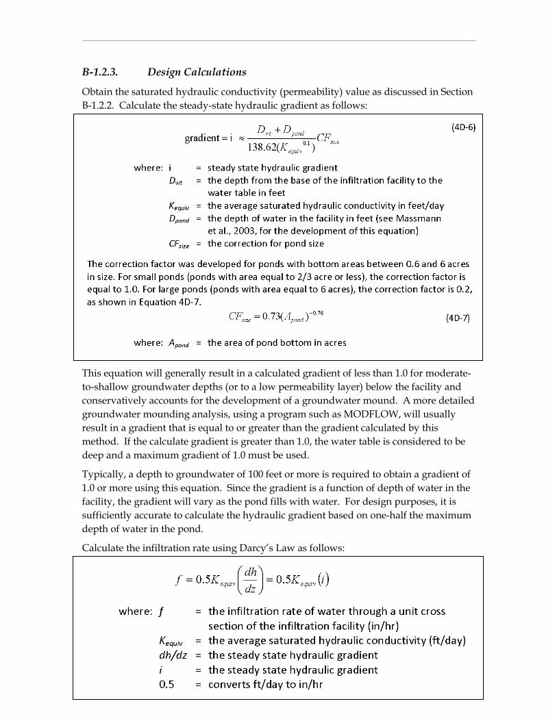
ERM 6 7/20/2014
B-1.2.3. Design Calculations
Obtain the saturated hydraulic conductivity (permeability) value as discussed in Section B-1.2.2. Calculate the steady-state hydraulic gradient as follows:
This equation will generally result in a calculated gradient of less than 1.0 for moderate-to-shallow groundwater depths (or to a low permeability layer) below the facility and conservatively accounts for the development of a groundwater mound. A more detailed groundwater mounding analysis, using a program such as MODFLOW, will usually result in a gradient that is equal to or greater than the gradient calculated by this method. If the calculate gradient is greater than 1.0, the water table is considered to be deep and a maximum gradient of 1.0 must be used.
Typically, a depth to groundwater of 100 feet or more is required to obtain a gradient of 1.0 or more using this equation. Since the gradient is a function of depth of water in the facility, the gradient will vary as the pond fills with water. For design purposes, it is sufficiently accurate to calculate the hydraulic gradient based on one-half the maximum depth of water in the pond.
Calculate the infiltration rate using Darcy’s Law as follows:

ERM 7 7/20/2014
The infiltration rate given above was developed assuming that the hydraulic conductivity of the soil beneath the infiltration facility will remain equal to the initial value. However, siltation or biofouling may reduce the long-term infiltration rates. Multiply the infiltration rate estimated above by the appropriate reduction factor listed below to obtain the design infiltration rate.
Additionally the infiltration rate should be adjusted to account for the effect of pond aspect ratio correction factor CFaspect, as shown in the following equation. In no case shall CFaspect be greater than 1.4.
B-1.2.4. General Requirements
Infiltration basins with an impounding levee greater than 5 feet tall, measured from the lowest point in the impounding area to the highest point of the levee, and basins capable of impounding over 30,000 cubic feet, should be designed by a professional Civil Engineer registered with the State of Alaska. Infiltration basins that meet the requirements of the Alaska Dam Safety Program must obtain a Certificate of Approval to Construct, Modify, Remove, or Abandon a Dam prior to being constructed. A Certificate of Approval to Operate a Dam is also required before a new dam can be put into operation. Please refer to Alaska Statue 11 AAC 93, Article 3 Dam Safety for additional requirements and details. Infiltration basins, regardless of size and storage volume, shall include an emergency overflow spillway.
Design the infiltration basin to a desirable depth of 3 feet and a maximum water level depth of 6 feet, with a minimum freeboard of 1 foot above the design water level.

ERM 8 7/20/2014
Lining - Basins can be open or covered with a 6 to 12-inch layer of filter material such as coarse sand, or suitable filter fabric to help prevent the buildup of impervious deposits on the soil surface. The filter layer can be replaced or cleaned if it becomes clogged.
Vegetation – The embankment, emergency spillway, spoil, and borrow areas, and any other disturbed area must be stabilized and re-vegetated. Vegetation growth should not be allowed to exceed 18 inches in height. Mow the slopes periodically and check for clogging and erosion.
Construction – As with all types of infiltration facilities, you should not use infiltration basins as temporary sediment traps during construction. If an infiltration pond is to be used as a sediment trap, do not excavate to final grade until after the upgradient drainage area has been stabilized. Remove any accumulation of silt in the basin before it is put into service.
B-1.3. Maintenance Considerations Provision should be made for regular maintenance of the infiltration basin, including replacement and/or reconstruction of any media that are relied upon for treatment purposes. Maintenance should be conducted on a regular basis in accordance with an Operation and Maintenance Plan for the facility. Removal of debris/sediment in the basin should be performed as needed to prevent clogging or when the sediment pre-settling cell is full.
Source: Washington State Department of Ecology. 2012. Stormwater Management Manual for Western Washington: Volume III – Hydrologic Analysis and Flow Control Design/BMPs.
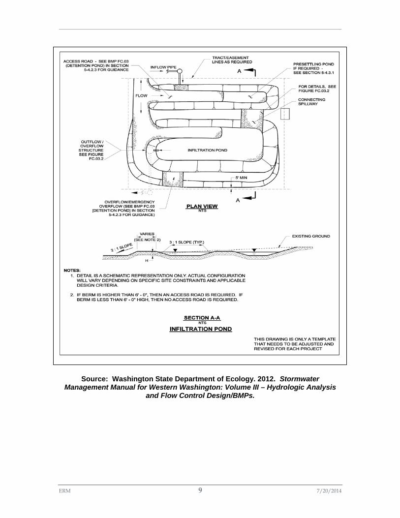
ERM 9 7/20/2014
Source: Washington State Department of Ecology. 2012. Stormwater
Management Manual for Western Washington: Volume III – Hydrologic Analysis and Flow Control Design/BMPs.

ERM 10 7/20/2014
- Page Intentionally Left Blank -

ERM 11 7/20/2014
B-2. INFILTRATION TRENCH
INFILTRATION TRENCH
(Source: Controlling Urban Runoff: A Practical Manual for Planning and Designing Urban
BMPs. Metropolitan Washington Council of Governments (Scheuler), 1987)
B-2.1. Purpose and Application Infiltration trenches are long, narrow, stone-filled trenches used for the collection, temporary storage, and infiltration of wastewater to groundwater. They can be a useful alternative for sites with constraints that make siting an infiltration pond difficult. Infiltration trenches reduce land space requirements by allowing infiltration of wastewater below the ground. They effectively control pollutants in wastewater discharge by preventing surface runoff, but are not intended for control of sediment because of potential for clogging.
Infiltration trenches have a similar advantage to infiltration basins in that the generally observed finer grained (lower permeability) surface soils found in the North Pole area are removed and replaced by highly permeable materials such as sand and gravel.

ERM 12 7/20/2014
B-2.2. Planning and Design Considerations or General Requirements Infiltration trenches may range from three or more feet in depth depending on wastewater discharge volume, soil and water table conditions with trench bottoms being at least two feet above the water table.
Stormwater diversion ditches should be considered to divert any stormwater runoff around the infiltration trench to prevent overloading, sedimentation, and maximize the infiltration capacity for the excavation dewatering project.
Additional measures may be required for use with infiltration trenches to ensure that wastewater discharges are not allowed to escape and enter surface water bodies (waters of the U.S.).
B-2.2.1. Site Soil Permeability
Underlying soil should have a permeability of 0.5 inches per hour or higher. If necessary lower permeability materials may need to be removed to have adequate infiltration rates. Note that permeability, also called “hydraulic conductivity”, as opposed to infiltration rate, should be used to define the rate at which water can seep into the bottom and of an infiltration trench. Infiltration rate is the actual calculated rate of water decline within the infiltration trench or structure. Surface soil permeability rates are available on the Natural Resource Conservation Service (NRSC) Soil Survey Information website at: http://www.ak.nrcs.usda.gov/soils/index.html or http://websoilsurvey.nrcs.usda.gov/app/HomePage.htm for general soil information of your project area. A geologic investigation of the site, however, is always the preferable method of obtaining a permeability value. Several methods of measuring soil permeability have been developed. The most commonly used method is the falling head percolation test. This method is described in detail in:
• Onsite Wastewater Treatment and Disposal System Design Manual. 1980. EPA, pp 39-49.
A minimum of two percolation test locations should be selected that are within the actual location of the proposed infiltration trench to identify localized soil conditions. Trenches over 100 feet in length should include at least one additional test location for each 50 foot increment. Where feasible, larger-scale measurements of permeability are encouraged, using a procedure such as the Pilot Infiltration Test described in the State of Washington’s Stormwater Management Manual.
B-2.2.2. Design Calculations
Obtain the saturated hydraulic conductivity (permeability) value as discussed in Section 3.2.1. Calculate the hydraulic gradient for the trench as follows:
These calculation methods were obtained from Massmann (2003) and are applicable for trenches with flat or shallow slopes – not to be used for slopes greater than 0.5%. If the calculated gradient is greater than 1.0, the water table is considered to be deep and you
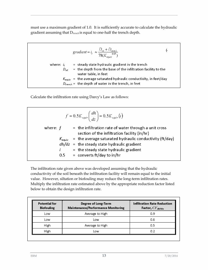
ERM 13 7/20/2014
must use a maximum gradient of 1.0. It is sufficiently accurate to calculate the hydraulic gradient assuming that Dtrench is equal to one-half the trench depth.
Calculate the infiltration rate using Darcy’s Law as follows:
The infiltration rate given above was developed assuming that the hydraulic conductivity of the soil beneath the infiltration facility will remain equal to the initial value. However, siltation or biofouling may reduce the long-term infiltration rates. Multiply the infiltration rate estimated above by the appropriate reduction factor listed below to obtain the design infiltration rate.
ERM 14 7/20/2014
B-2.2.3. Filter Fabric and Storage Media
The sides and bottom of the infiltration trench should be lined with geotextile fabric (filter fabric). Also, there can be a layer of nonwoven fabric 6 to 12 inches below ground surface (bgs) inside the trench to prevent suspended solids from clogging the majority of the storage media. It should be recognized, however, that there may need to be frequent cleaning and replacement of the material above the filter fabric to prevent clogging of the trench.
The filter fabric material must be compatible with the surrounding soil textures and application purposes. The cut width of the filter fabric must have sufficient material for a minimum 12-inch overlap and key in on each side of the trench. When overlaps are required along the length of the trench, the upstream section must overlap the downstream section by 24-inches to provide a shingled effect. The bottom of the trench can be covered with a six to twelve inch layer of clean sand in place of filter fabric.
The basic infiltration trench design utilizes stone aggregate inside the filter fabric to provide water storage. The trench should be filled with clean, washed stone having a diameter of 1.5 to 3 inches. This aggregate size provides a void space of 40 percent. This design can be modified by substituting pea gravel for stone aggregate in the top 12 inches of the trench. The pea gravel improves sediment filtering in the top of the trench. When the modified trenches become clogged, they can generally be restored to full performance by removing and replacing only the pea gravel layer, without needing to replace the lower stone aggregate material.
It should be noted that while stone is the most common form of storage media in infiltration trenches, there are suppliers that manufacture precast infiltration storage media. These alternative storage media solutions are generally acceptable, but will need to be reviewed and approved on a case by case basis.
B-2.2.4. Observation Well
An observation well located at the center, or both ends, of the trench is recommended to monitor water drainage from the system. The well can be 4 to 6 inch diameter PVC pipe, which is anchored vertically to a foot plate at the bottom of the trench. This well should have a lockable above-ground cap.
B-2.3. Maintenance Considerations Maintenance is required for the proper operation of infiltration trenches as it is with all BMPs. Plans for infiltration trenches should identify owners, parties responsible for maintenance, and an inspection and maintenance schedule.
Care should be taken to eliminate or greatly reduce clogging of infiltration trenches due to sedimentation. Depending on the sediment content of the wastewater discharge pretreatment filtering may be required prior to entering the infiltration trench.
ERM 15 7/20/2014
Once the trench has gone online, inspections should be performed on a routine basis to ensure the infiltration trench is operating as intended. Water levels in the observation well should be recorded over several days to check trench drainage rates. Immediate repair or replacement will be required if water ponding or escapement is observed.
Ponded water inside the trench (as visible from the observation well) after 24 hours or several days after a discharge event often indicates that the bottom of the trench is clogged. In this case, all of the stone aggregate and filter fabric or media must be removed. Accumulated sediment removed from the bottom and the bottom scarified or tilled to help induce infiltration. New fabric and clean stone aggregate should be refilled.
Infiltration trenches will need to be removed at the end of an excavation dewatering project unless permission is obtained to leave the structure permanently in place.
Source: Washington State Department of Ecology. 2012. Stormwater Management Manual for Western Washington: Volume III – Hydrologic Analysis and Flow Control Design/BMPs.

ERM 16 7/20/2014
Source: WSDOT. 2014. Highway Runoff Manual.

ERM 17 7/20/2014
B-3. LAND APPLICATION DISPERSAL
LAND APPLICATION DISPERSAL
B-3.1. Purpose and Application Land application dispersal sends wastewater through a dispersal system to prevent point source discharges. Land application dispersal has the advantage of spreading the wastewater over a larger area for better removal of sediment by vegetated areas (vegetative filtration) and improved infiltration due to the larger surface area that the discharge is spread over.
The simplest wastewater distribution system is to lay out perforated pipes parallel to the slope contours.
B-3.2. Planning and Design Considerations or General Requirements Find land adjacent to the project site that has a vegetated field, preferably a wooded area or farm field. Install a pump and downstream distribution manifold depending on the project size. Generally, the main distribution line should reach 100 to 200-feet long (however, larger projects may require systems that reach several thousand feet long with numerous branch lines off the main distribution line). The manifold should have several valves to allow for control over the distribution of the wastewater across the field.

ERM 18 7/20/2014
On relatively even surfaces, a level spreader using 4-inch perforated pipe may be used. Install drain pipe at the highest point on the field and at various lower elevations to ensure full coverage of the filtration area. Pipe should be laid with holes up to allow for a gentle weeping of wastewater evenly out all holes. Leveling pipe by staking and using sandbags may be required. On uneven ground, sprinklers may be used. Space sprinkler heads so that spray patterns do no overlap.
Monitor the field distribution area several times per day to ensure that over saturation of any portion of the field doesn’t occur at any time. The presence of standing puddles of water or creation of concentrated flows visually signify that oversaturation of the field has occurred. To prevent the over saturation of the field area, rotate the use of branches or spray heads.
Since the water contains sulfolane it is imperative that physical monitoring of the vegetated field extend beyond the furthest distribution area, to ensure that the water has not caused overland or concentrated flows. Infiltration must be complete as wastewater discharges are not allowed to enter waters of the U.S. Additional flow control structures such as diversion ditches or shallow impoundments may be needed to ensure no escapement of water.
If escapement of water does occur it must be reported to the Division of Water within 24 hours.
B-3.3. Maintenance Considerations Maintenance is required for the proper operation of all BMPs. Plans for land application dispersal should identify owners, parties responsible for maintenance, and an inspection and maintenance schedule.
If erosion, concentrated flows, or over saturation of the field occurs, immediate action is needed to correct the problem. Rotation of the distribution branches or spray heads may be used to provide a temporary solution.

ERM 19 7/20/2014
LAND APPLICATION: DISPERSAL
(Source: Washington State DNR, 1997)

ERM 20 7/20/2014
- Page Intentionally Left Blank -

ERM 21 7/20/2014
B-4. CHECK DAM
ROCK CHECK DAM
(Source: Washington State DNR, 1997)
B-4.1. Purpose and Application Check dams reduce scour and channel erosion by reducing flow velocity and encouraging sediment settlement. They can also be used to promote additional infiltration. The dam configuration supports sediment settling from silted waters pooled behind the weir and allows additional time for water infiltration. A check dam is a small device constructed of rock, gravel bags, sandbags, fiber rolls, or other proprietary product placed across a natural or man-made channel or drainage ditch. Check dams are generally placed in a series along the channel or drainage way.
B-4.2. Planning and Design Considerations or General Requirements In general there are several important factors that need to be considered in the design and construction of check dam structures. These factors include:
• Location of Site – the general topography of the land plays an important role in the design and construction of the check dam. If possible, the site selected should be able to provide a long length and large volume of stored water to maximize infiltration capacity. Existing drainage pattern must be evaluated to determine if they can be diverted or must be considered in the check dam design.

ERM 22 7/20/2014
Check dams should not be placed in active or high flow waterways unless they are designed to convey the required flows.
• Durability of Check Dam – check dams can be built using various types of materials such as rocks, timber (sawn or logs), sand bags, gabions, or concrete (cast-in-situ or precast forms). For temporary purposes during excavation dewatering the most likely materials are rocks with a liner material to minimize leakage and sand bags.
• Seepage Control – seepage is to be anticipated in a check dam structure either through its embankment or foundation. To control the desired water level in the waterway and maximize infiltration, excessive loss of impounded water must be minimized. For this purpose, the check dam design should incorporate an impermeable layer such as HDPE sheet in the embankment and foundation, use of low permeability materials such as clayey soil in embankment and foundation, or installation of a vertical cut-off such as interlocking sheet piles, if necessary.
• Infiltration Control – to promote infiltration low permeability surface materials may be removed and replaced with permeable materials within the ponded area of the structure. However, it is important to maintain seepage control underneath the embankment to prevent downstream loss of water.
• General Layout – The center of the check dam should be at least 6 inches lower than either edge, so as to form an outfall weir, and to allow normal flows spilling to occur within the mid portion of the structure. Stabilizing protection should be provided immediately downstream of the check dam to prevent any possible toe erosion and undercutting. The embankments of the check dam should be extended adequately into the existing bank to prevent excess seepage and potential breaching of the banks. For a multiple check dam installation, backwater from the downsteam check dam shall reach the toe of the upstream check dam (see check dam detail).
Stormwater diversion ditches should be considered to divert any stormwater runoff around the check dam to prevent overloading, sedimentation, and maximize the infiltration capacity for the excavation dewatering project.
Additional measures may be required for use of check dams to ensure that wastewater discharges are not allowed to escape and enter surface water bodies (waters of the U.S.).
B-4.3. Maintenance Considerations Inspections should be performed on a routine basis to ensure the check dam is functional and that sedimentation is not preventing adequate infiltration of the wastewater. Routine maintenance will include sediment removal if water escapement is observed or infiltration rates are no longer acceptable.
Check dams will need to be removed at the end of an excavation dewatering project including any accumulated sediment that has been trapped by the dam to prevent

ERM 23 7/20/2014
sediment re-suspension during any subsequent stormwater events. Removed sediment shall be incorporated in the project at locations designated by the Permit and disposed of outside the roadway right-of-way.
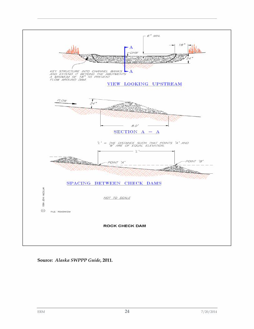
ERM 24 7/20/2014
Source: Alaska SWPPP Guide, 2011.
ERM 25 7/20/2014
B-5. REFERENCES
Alaska Department of Transportation and Public Facilities. 2011. Alaska Storm Water Pollution Prevention Plan Guide.
Florida Department of Environmental Protection. 2003. Stormwater Best Management Practice (BMP) Selection and Implementation.
Massman, J.W. 2003. A Design Manual for Sizing Infiltration Ponds. WSDOT, WA-RD 578.2. 61pp.
New Jersey. 2004. New Jersey Stormwater Best Management Practices Manual. Chapter 9.5: Standard for Infiltration Basins. 11pp.
Washington State Department of Ecology. 2012. Stormwater Management Manual for Western Washington: Volume III – Hydrologic Analysis and Flow Control Design/BMPs.
Washington State Department of Natural Resources. 1997. Best Management Practices for Reclaiming Surface Mines in Washington and Oregon.
Washington State Department of Transportation. 2014. Highway Runoff Manual. M 31-16.04.

ERM 26 7/20/2014
- Page Intentionally Left Blank -