
Interference Suppression Film Capacitors MKP Radial Potted ... · Interference Suppression Film...
19
Interference Suppression Film Capacitors MKP Radial Potted Type MKP 338 2 X2 Vishay BCcomponents www.vishay.com For technical questions, contact: [email protected] Document Number: 28119 145 Revision: 06-Jul-07 NO FOCUS PRODUCT: USE MKP 339 X2 APPLICATIONS X2 class For X2 electromagnetic interference suppression in across the line applications (50/60 Hz) with a maximum mains voltage of 275 Vac. For application limitations please refer page 14. REFERENCE STANDARDS “IEC 60384-14 2nd edition and EN 132400” “IEC 60065 requires pass flamm class B” 250 V: UL1414; CSA-C22.2 No 1 275 V: CSA-C22.2 No 8 ENEC; CQC 305 V: UL1283 MARKING C-value; tolerance; rated voltage; sub-class; manufacturer’s type designation; code for dielectric material, manufacturer location; manufacturer’s emblem; year and week DIELECTRIC Polypropylene film ELECTRODES Metallized film CONSTRUCTION Mono construction RATED VOLTAGE AC 275 V; 50 to 60 Hz FEATURES 7.5 to 27.5 mm lead pitch. Supplied in box, taped on ammopack or reel Lead (Pb)-free product RoHS-compliant product PERMISSIBLE DC VOLTAGE DC 630 V ENCAPSULATION Plastic case, epoxy resin sealed, flame retardant UL-class 94 V-0 CLIMATIC TESTING CLASS ACC. TO EN 60068-1 55/110/56/B CAPACITANCE RANGE (E12 SERIES) E12 series 0.001 to 3.3 μF Preferred values acc. to E6 CAPACITANCE TOLERANCE ± 20 %; ± 10 %; ± 5 % LEADS Tinned wire MAXIMUM APPLICATION TEMPERATURE 110 °C DETAIL SPECIFICATION For more detailed data and test requirements contact: [email protected] Dimensions in mm ⎪F − F " ⎪< 0.3 mm F = 7.5 + 0.6/- 0.1 mm 168x12(halfpage) 168x12(halfpage) w l P h l h h' w H F 10 F' (1) 15 l t Ø d t Ø d t e3 RoHS COMPLIANT
Transcript of Interference Suppression Film Capacitors MKP Radial Potted ... · Interference Suppression Film...
Interference Suppression Film CapacitorsMKP Radial Potted Type
MKP 338 2 X2Vishay BCcomponents
www.vishay.com For technical questions, contact: [email protected] Document Number: 28119145 Revision: 06-Jul-07
NO FOCUS PRODUCT: USE MKP 339 X2
APPLICATIONS
X2 class
For X2 electromagnetic interference suppression in acrossthe line applications (50/60 Hz) with a maximum mainsvoltage of 275 Vac.
For application limitations please refer page 14.
REFERENCE STANDARDS
“IEC 60384-14 2nd edition and EN 132400”“IEC 60065 requires pass flamm class B”250 V: UL1414; CSA-C22.2 No 1275 V: CSA-C22.2 No 8 ENEC; CQC305 V: UL1283
MARKING
C-value; tolerance; rated voltage; sub-class; manufacturer’stype designation; code for dielectric material, manufacturerlocation; manufacturer’s emblem; year and week
DIELECTRIC
Polypropylene film
ELECTRODES
Metallized film
CONSTRUCTION
Mono construction
RATED VOLTAGE
AC 275 V; 50 to 60 Hz
FEATURES
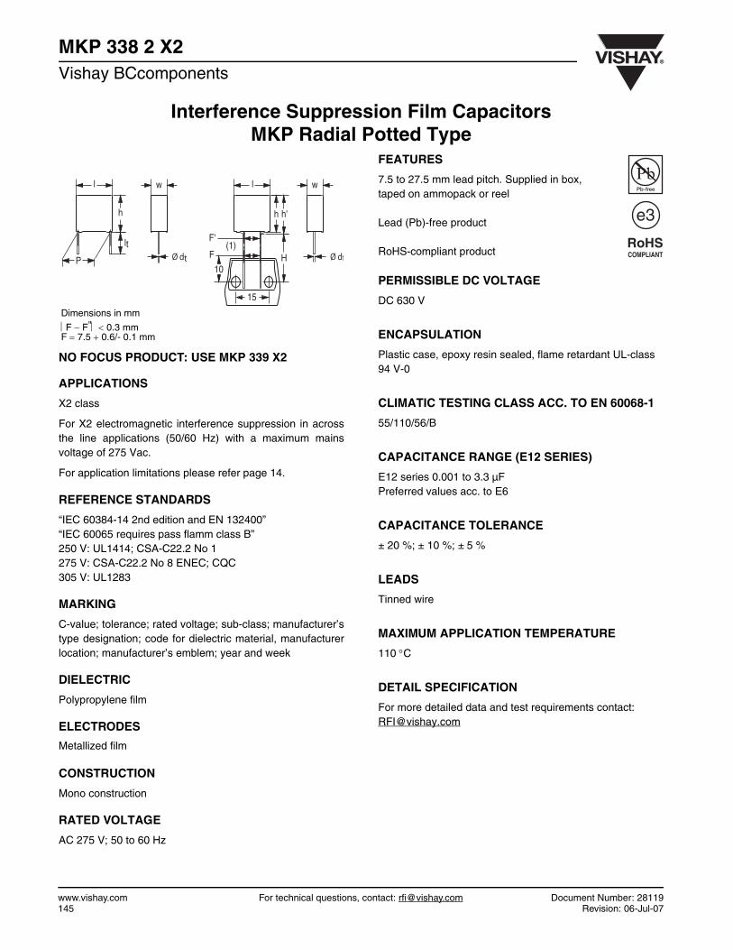
7.5 to 27.5 mm lead pitch. Supplied in box,taped on ammopack or reel
Lead (Pb)-free product
RoHS-compliant product
PERMISSIBLE DC VOLTAGE
DC 630 V
ENCAPSULATION
Plastic case, epoxy resin sealed, flame retardant UL-class 94 V-0
CLIMATIC TESTING CLASS ACC. TO EN 60068-1
55/110/56/B
CAPACITANCE RANGE (E12 SERIES)
E12 series 0.001 to 3.3 µFPreferred values acc. to E6
CAPACITANCE TOLERANCE
± 20 %; ± 10 %; ± 5 %
LEADS
Tinned wire
MAXIMUM APPLICATION TEMPERATURE
110 °C
DETAIL SPECIFICATION
For more detailed data and test requirements contact:[email protected]
Dimensions in mm
⎪F − F"⎪ < 0.3 mmF = 7.5 + 0.6/- 0.1 mm
168x12(halfpage)168x12(halfpage) wl
P
h
l
h h'
w
HF
10
F'(1)
15
ltØ dt Ø dt
e3
RoHSCOMPLIANT

Document Number: 28119 For technical questions, contact: [email protected] www.vishay.comRevision: 06-Jul-07 146
MKP 338 2 X2Interference Suppression Film Capacitors
MKP Radial Potted TypeVishay BCcomponents
COMPOSITION OF CATALOG NUMBER
SPECIFIC REFERENCE DATA FOR THE 275 V AC (X2) CAPACITORS
TYPE PACKAGING STANDARD DIMENSIONS C-TOL PREFERRED TYPES
338 2 X2
loose in boxlead length 3.5 + 1/- 0.5 mm or 3.5 ± 0.3 mm
± 20 %
BFC2 338 20...lead length 5.0 ± 1.0 mm BFC2 338 22...lead length 25.0 ± 2.0 mm BFC2 338 24...
taped Pitch 7.5 mm or bent back to 7.5 mm BFC2 338 26...
PACKAGING ALTERNATIVE LARGER PITCH SIZES C-TOL ON REQUEST
loose in boxlead length 3.5 + 1/- 0.5 mm or 3.5 ± 0.3 mm
± 20 % see tables for detailslead length 5.0 ± 1.0 mmlead length 25.0 ± 2.0 mm
PACKAGING ALTERNATIVE TAPED VERSION(1) ON REQUEST
taped H = 18.5 mm; P0 = 12.7 mm(2) ± 20 % see tables for details
PACKAGING ALTERNATIVE C-TOL ON REQUEST
loose in box
lead length 3.5 + 1/- 0.5 mm or 3.5 ± 0.3 mm ± 10 %± 5 %
lead length 5.0 ± 1.0 mm ± 10 %± 5 %
lead length 25.0 ± 2.0 mm ± 10 %± 5 % see tables for details
tapedpitch 7.5 mm or bent back to 7.5 mm ± 10 %
± 5 %
H = 18.5 mm; P0 = 12.7 mm ± 10 %± 5 %
Notes1. Taped on reel pitch = 27.5 mm is not available2. For detailed tape specifications refer to “Packaging information” www.vishay.com/docs/28139/packinfo.pdf
MULTIPLIER(nF)
0.1 21 3
10 4100 5
CAPACITANCE
(numerically)
Example:
104 = 10 x 10 = 100 nF
TYPE AND PITCHES
338 2
X2
7.5 mm7.5 mm (bent back)
10.0 mm15.0 mm22.5 mm27.5 mm
BFC2 338 2X XX X2222(*) 338 2X XX X
(*) Old ordering code
DESCRIPTION VALUE
Tangent of loss angle: at 1 kHz at 10 kHzC ≤ 470 nF ≤ 10 × 10-4 ≤ 20 × 10-4
470 nF < C ≤ 1 µF ≤ 20 × 10-4 ≤ 70 × 10-4
C > 1 µF ≤ 30 × 10-4 -Rated voltage pulse slope (dU/dt)R at 385 V (DC) 100 V/µsR between leads, for C ≤ 0.33 µF at 100 V; 1 minute > 15 000 MΩRC between leads, for C > 0.33 µF at 100 V; 1 minute > 5000 sR between leads and case; 100 V; 1 minute > 30 000 MΩWithstanding (DC) voltage (cut off current 10 mA); rise time 100 V/s:C ≤ 1µF 2200 V; 1 minC > 1µF 1800 V; 1 minWithstanding (AC) voltage between leads and case 2050 V; 1 minMaximum application temperature 110 °C

www.vishay.com For technical questions, contact: [email protected] Document Number: 28119147 Revision: 06-Jul-07
MKP 338 2 X2Vishay BCcomponents Interference Suppression Film Capacitors
MKP Radial Potted Type
Note1. Weight for short lead product only
Pitch: 7.5 mm; C-tol = ± 20 % (for reference: URdc = 630 V) URac = 275 V
C(µF)
DIMENSIONSW x H x L
(mm)
MASS(g)(1)
CATALOG NUMBER BFC2 338 2..... AND PACKAGING
LOOSE IN BOX AMMOPACK
Short leads Long leads H = 18.5 mmP0 = 12.7 mm
lt =3.5 + 1/- 0.5 mm
lt =5.0 ± 1.0 mm SPQ lt =
25.0 ± 2.0 mm SPQ SPQ
Pitch = 7.5 ± 0.4 mm; dt = 0.50 ± 0.05 mm0.001
4.0 × 9.0 × 10.0 0.4
20102 22102
1500
24102
1000
26102
1250
0.0012 20122 22122 24122 261220.0015 20152 22152 24152 261520.0018 20182 22182 24182 261820.0022 20222 22222 24222 262220.0027 20272 22272 24272 262720.0033 20332 22332 24332 263320.0039 20392 22392 24392 263920.0047 20472 22472 24472 264720.0056 20562 22562 24562 265620.0068 20682 22682 24682 266820.0082 20822 22822 24822 268220.01 20103 22103 24103 261030.012 20123 22123 24123 261230.015 20153 22153 24153 261530.018 20183 22183 24183 261830.022 20223 22223 24223 262230.027 20273 22273 1000 24273 1250 26273 10000.033 20333 22333 24333 263330.039 5.0 x 10.5 x 10.0 0.6 20393 22393 750 24393 1000 26393 7500.047 20473 22473 24473 26473
Pitch: 7.5 mm; C-tol = ± 10 % (for reference: URdc = 630 V) URac = 275 V
C(µF)
DIMENSIONSW x H x L
(mm)
MASS(g)(1)
CATALOG NUMBER BFC2 338 2 ..... AND PACKAGING
LOOSE IN BOX AMMOPACK
Short leads Long leads H = 18.5 mmP0 = 12.7 mm
lt =3.5 + 1/- 0.5 mm
lt =5.0 ± 1.0 mm SPQ lt =
25.0 ± 2.0 mm SPQ SPQ
Pitch = 7.5 ± 0.4 mm; dt = 0.50 ± 0.05 mm0.001
4.0 x 9.0 x 10.0 0.4
28101 28301
1500
28501
1000
28701
1250
0.0012 28102 28302 28502 287020.0015 28103 28303 28503 287030.0018 28104 28304 28504 287040.0022 28105 28305 28505 287050.0027 28106 28306 28506 287060.0033 28107 28307 28507 287070.0039 28108 28308 28508 287080.0047 28109 28309 28509 287090.0056 28111 28311 28511 287110.0068 28112 28312 28512 287120.0082 28113 28313 28513 287130.01 28114 28314 28514 287140.012 28115 28315 28515 287150.015 28116 28316 28516 287160.018 28117 28317 28517 287170.022 28118 28318 28518 287180.027 28119 28319
100028519
125028719
10000.033
5.0 x 10.5 x 10.0 0.628121 28321 28521 28721
0.039 28122 28332750
285221000
28722750
0.047 6.0 x 11.5 x 10.0 0.8 28123 28323 28523 28723

Document Number: 28119 For technical questions, contact: [email protected] www.vishay.comRevision: 06-Jul-07 148
MKP 338 2 X2Interference Suppression Film Capacitors
MKP Radial Potted TypeVishay BCcomponents
Notes
1. Reel diameter = 356 mm is available on request2. Weight for short lead product only
Pitch: 7.5 mm; C-tol = ± 5 % (for reference: URdc = 630 V) URac = 275 V
C(µF)
DIMENSIONSW x H x L
(mm)
MASS(g)(1)
CATALOG NUMBER BFC2 338 2 ..... AND PACKAGING
LOOSE IN BOX AMMOPACK
Short leads Long leads H = 18.5 mmP0 = 12.7 mm
lt =3.5 + 1/- 0.5 mm(2)
lt =5.0 ± 1.0 mm SPQ lt =
25.0 ± 2.0 mm SPQ SPQ
Pitch = 7.5 ± 0.4 mm; dt = 0.50 ± 0.05 mm
0.001
4.0 x 9.0 x 10.0 0.4
28201 28401
1500
28601
1000
28801
1250
0.0012 28202 28402 28602 288020.0015 28203 28403 28603 288030.0018 28204 28404 28604 288040.0022 28205 28405 28605 288050.0027 28206 28406 28606 288060.0033 28207 28407 28607 288070.0039 28208 28408 28608 288080.0047 28209 28409 28609 288090.0056 28211 28411 28611 288110.0068 28212 28412 28612 288120.0082 28213 28413 28613 288130.01 28214 28414 28614 288140.012 28215 28415 28615 288150.015 28216 28416 28616 288160.018 28217 28417 28617 288170.022 28218 28418 28618 288180.027 28219 28419 1000 28619 1250 28819 10000.033
5.0 x 10.5 x 10.0 0.628221 28421 1000 28621 1250 28821 1000
0.039 28222 28422 750 28622 1000 28822 7500.047 6.0 x 11.5 x 10.0 0.8 28223 28423 750 28623 1000 28823 750
Bent back pitch: 7.5 mm (only taped); C-tol = ± 20 % (for reference: URdc = 630 V)
C(µF)
DIMENSIONSW x H x L
(mm)
MASS(g)(2)
CATALOG NUMBER BFC2 338 ..... AND PACKAGING
REEL (500 mm)(1)
H = 16.0 mm; P0 = 15.0 mm SPQ
Bent back pitch = 7.5 ± 0.4 mm; dt = 0.60 ± 0.06 mm0.056
5.0 x 13.0 x 12.5 0.8226563
16000.068 266830.082
6.0 x 14.0 x 12.5 1.126823
16000.1 26104Bent back pitch = 7.5 ± 0.4 mm; dt = 0.60 ± 0.06 mm0.12 5.0 x 13.0 x 17.5 1.0 26124 8000.15
6.0 x 14.0 x 17.5 1.426154
7000.18 26184Bent back pitch = 7.5 ± 0.4 mm; dt = 0.60 ± 0.06 mm0.22 7.0 x 15.5 x 17.5 1.8 26224 5500.27
8.5 x 17.0 x 17.5 2.426274 550
0.33 26334 500

www.vishay.com For technical questions, contact: [email protected] Document Number: 28119149 Revision: 06-Jul-07
MKP 338 2 X2Vishay BCcomponents Interference Suppression Film Capacitors
MKP Radial Potted Type
Notes1. Reel diameter = 356 mm is available on request2. Weight for short lead product only
Notes1. Reel diameter = 356 mm is available on request2. Weight for short lead product only
Bent back pitch: 7.5 mm (only taped); C-tol = ± 10 % (for reference: URdc = 630 V)
C(µF)
DIMENSIONSW x H x L
(mm)
MASS(g)(2)
CATALOG NUMBER BFC2 338 2 .....AND PACKAGING
REEL (500 mm) (1)
H = 16.0 mm; P0 = 15.0 mm SPQ
Bent back pitch = 7.5 ± 0.4 mm; dt = 0.60 ± 0.06 mm
0.0565.0 x 13.0 x 12.5 0.82
287241600
0.068 287250.082 6.0 x 14.0 x 12.5 1.1 28726 1600Bent back pitch = 7.5 ± 0.4 mm; dt = 0.60 ± 0.06 mm0.1 5.0 x 13.0 x 17.5 1.0 28727 8000.12
6.0 x 14.0 x 17.5 1.428728
7000.15 28729Bent back pitch = 7.5 ± 0.4 mm; dt = 0.80 ± 0.08 mm0.18
7.0 x 15.5 x 17.5 1.828731
5500.22 287320.27
8.5 x 17.0 x 17.5 2.428733
5000.33 29168
Bent back pitch: 7.5 mm (only taped); C-tol = ± 5 % (for reference: URdc = 630 V)
C(µF)
DIMENSIONSW x H x L
(mm)
MASS(g)(2)
CATALOG NUMBER BFC2 338 2 ..... AND PACKAGINGREEL (500 mm)(1)
H = 16.0 mm; P0 = 15.0 mm SPQBent back pitch = 7.5 ± 0.4 mm; dt = 0.60 ± 0.06 mm0.056
6.0 x 14.0 x 12.5 1.128824
16000.068 288250.082 28826Bent back pitch = 7.5 ± 0.4 mm; dt = 0.60 ± 0.06 mm0.1 5.0 x 13.0 x 17.5 1.0 28827 8000.12
6.0 x 14.0 x 17.5 1.428828
7000.15 28829Bent back pitch = 7.5 ± 0.4 mm; dt = 0.60 ± 0.06 mm0.18 7.0 x 15.5 x 17.5 1.8 28831 5500.22
8.5 x 17.0 x 17.5 2.428832 550
0.27 28833 500

Document Number: 28119 For technical questions, contact: [email protected] www.vishay.comRevision: 06-Jul-07 150
MKP 338 2 X2Interference Suppression Film Capacitors
MKP Radial Potted TypeVishay BCcomponents
Note1. Weight for short lead product only
Pitch: 10.0 mm; C-tol = ± 20 % (for reference: URDC = 630 V) URac = 275 V
C(µF)
DIMENSIONSW x H x L
(mm)
MASS(g)(1)
CATALOG NUMBER BFC2 338 2 ..... AND PACKAGING
LOOSE IN BOX AMMOPACK
Short leads Long leads H = 18.5 mmP0 = 12.7 mm
lt =3.5 + 1/- 0.5 mm
lt =5.0 ± 1.0 mm SPQ lt =
25.0 ± 2.0 mm SPQ SPQ
Pitch = 10.0 ± 0.4 mm; dt = 0.60 ± 0.06 mm0.001
4.0 x 10.0 x 12.5 0.6
21102 23102
1000
25102
1250
Not available
0.0012 21122 23122 251220.0015 21152 23152 251520.0018 21182 23182 251820.0022 21222 23222 252220.0027 21272 23272 25272
1000
0.0033 21332 23332 253320.0039 21392 23392 253920.0047 21472 23472 254720.0056 21562 23562 255620.0068 21682 23682 256820.0082 21822 23822 258220.01 21103 23103 251030.012 21123 23123 251230.015 21153 23153 251530.018 21183 23183 251830.022 21223 23223 252230.027 21273 23273 252730.033 21333 23333 253330.039 21393 23393 253930.047 21473 23473 254730.056
5.0 x 11.0 x 12.5 0.8220563 22563
75024563
75027563
5000.068 20683 22683 24683 276830.082
6.0 x 12.0 x 12.5 1.120823 22823
75024823
75027823
5000.1 20104 22104 24104 27104
Pitch: 10.0 mm; C-tol = ± 10 % (for reference: URDC = 630 V) URac = 275 V
C(µF)
DIMENSIONSW x H x L
(mm)
MASS(g)(1)
CATALOG NUMBER BFC2 338 2 ..... AND PACKAGING
LOOSE IN BOX AMMOPACK
Short leads Long leads H = 18.5 mmP0 = 12.7 mm
lt =3.5 + 1/- 0.5 mm
lt =5.0 ± 1.0 mm
SPQ lt =25.0 ± 2.0 mm
SPQ SPQ
Pitch = 10.0 ± 0.4 mm; dt = 0.60 ± 0.06 mm
0.001
4.0 x 10.0 x 12.5 0.6
29194 29217
1000
29241
1250
Not available
0.0012 29195 29218 292420.0015 29196 29219 292430.0018 29197 29221 292440.0022 29198 29222 292450.0027 29199 29223 29246
10000.0033 29201 29224 292470.0039 29202 29225 292480.0047 29203 29226 292490.0056 29204 29227 29251

www.vishay.com For technical questions, contact: [email protected] Document Number: 28119151 Revision: 06-Jul-07
MKP 338 2 X2Vishay BCcomponents Interference Suppression Film Capacitors
MKP Radial Potted Type
Note1. Weight for short lead product only
Note1. Weight for short lead product only
0.0068 29205 29228 29252
0.0082 29206 29229 29253
0.01 29207 29231 29254
0.012 29208 29232 29255
0.015 29209 29233 29256
0.018 4.0 x 10.0 x 12.5 0.6 29211 29234 1000 29257 1000 Not available
0.022 29212 29235 29258
0.027 29213 29236 29259
0.033 29214 29237 29261
0.039 29215 29238 29262
0.047 29216 29239 29263
0.056 5.0 x 11.0 x 12.5 0.82 28124 28324 750 28524 750 28924 500
0.068 28125 28325 28525 28925
0.082 6.0 x 12.0 x 12.5 1.1 28126 28326 750 28526 750 28926 500
Pitch: 10.0 mm; C-tol = ± 10 % (for reference: URDC = 630 V) URac = 275 V
C(µF)
DIMENSIONSW x H x L
(mm)
MASS(g)(1)
CATALOG NUMBER BFC2 338 2 ..... AND PACKAGING
LOOSE IN BOX AMMOPACK
Short leads Long leads H = 18.5 mmP0 = 12.7 mm
lt =3.5 + 1/- 0.5 mm
lt =5.0 ± 1.0 mm
SPQ lt =25.0 ± 2.0 mm
SPQ SPQ
Pitch: 10.0 mm; C-tol = ± 5 % (for reference: URDC = 630 V) URac = 275 V
C(µF)
DIMENSIONSW x H x L
(mm)
MASS(g)(1)
CATALOG NUMBER BFC2 338 2 ..... AND PACKAGING
LOOSE IN BOX AMMOPACK
Short leads Long leads H = 18.5 mmP0 = 12.7 mm
lt =3.5 + 1/- 0.5 mm
lt =5.0 ± 1.0 mm
SPQ lt =25.0 ± 2.0 mm
SPQ SPQ
Pitch = 10.0 ± 0.4 mm; dt = 0.60 ± 0.06 mm0.056 5.0 x 11.0 x 12.5 0.82 28224 28424 750 28624 750 28944 5000.068 6.0 x 12.0 x 12.5 1.1 28225 28425 750 28625 750 28945 5000.082 28226 28426 28626 28946
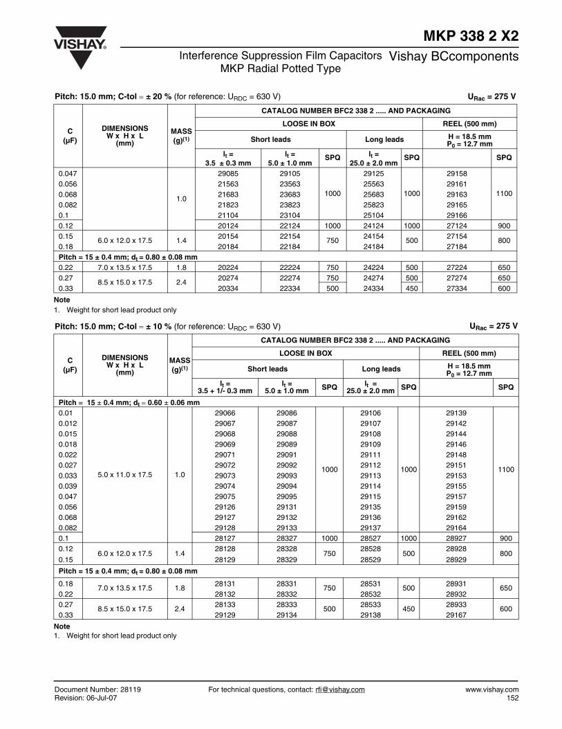
Pitch: 15.0 mm; C-tol = ± 20 % (for reference: URDC = 630 V) URac = 275 V
C(µF)
DIMENSIONSW x H x L
(mm)
MASS(g)(1)
CATALOG NUMBER BFC2 338 2 ..... AND PACKAGING
LOOSE IN BOX REEL (500 mm)
Short leads Long leads H = 18.5 mmP0 = 12.7 mm
lt =3.5 ± 0.3 mm
lt =5.0 ± 1.0 mm
SPQ lt =25.0 ± 2.0 mm
SPQ SPQ
Pitch = 15 ± 0.4 mm; dt = 0.60 ± 0.06 mm0.01
5.0 x 11.0 x 17.5 1.0
29076 29096
1000
29116
1000
29141
1100
0.012 29077 29097 29117 291430.015 29078 29098 29118 291450.018 29079 29099 29119 291470.022 29081 29101 29121 291490.027 29082 29102 29122 291520.033 29083 29103 29123 291540.039 29084 29104 29124 29156
Document Number: 28119 For technical questions, contact: [email protected] www.vishay.comRevision: 06-Jul-07 152
MKP 338 2 X2Interference Suppression Film Capacitors
MKP Radial Potted TypeVishay BCcomponents
Note1. Weight for short lead product only
Note 1. Weight for short lead product only
0.047
1.0
29085 29105
1000
29125
1000
29158
11000.056 21563 23563 25563 291610.068 21683 23683 25683 291630.082 21823 23823 25823 291650.1 21104 23104 25104 291660.12 20124 22124 1000 24124 1000 27124 9000.15
6.0 x 12.0 x 17.5 1.420154 22154
75024154
50027154
8000.18 20184 22184 24184 27184Pitch = 15 ± 0.4 mm; dt = 0.80 ± 0.08 mm0.22 7.0 x 13.5 x 17.5 1.8 20224 22224 750 24224 500 27224 6500.27
8.5 x 15.0 x 17.5 2.420274 22274 750 24274 500 27274 650
0.33 20334 22334 500 24334 450 27334 600
Pitch: 15.0 mm; C-tol = ± 20 % (for reference: URDC = 630 V) URac = 275 V
C(µF)
DIMENSIONSW x H x L
(mm)
MASS(g)(1)
CATALOG NUMBER BFC2 338 2 ..... AND PACKAGING
LOOSE IN BOX REEL (500 mm)
Short leads Long leads H = 18.5 mmP0 = 12.7 mm
lt =3.5 ± 0.3 mm
lt =5.0 ± 1.0 mm
SPQ lt =25.0 ± 2.0 mm
SPQ SPQ
Pitch: 15.0 mm; C-tol = ± 10 % (for reference: URDC = 630 V) URac = 275 V
C(µF)
DIMENSIONSW x H x L
(mm)
MASS(g)(1)
CATALOG NUMBER BFC2 338 2 ..... AND PACKAGING
LOOSE IN BOX REEL (500 mm)
Short leads Long leads H = 18.5 mmP0 = 12.7 mm
lt =3.5 + 1/- 0.3 mm
lt =5.0 ± 1.0 mm SPQ lt =
25.0 ± 2.0 mm SPQ SPQ
Pitch = 15 ± 0.4 mm; dt = 0.60 ± 0.06 mm0.01
5.0 x 11.0 x 17.5 1.0
29066 29086
1000
29106
1000
29139
1100
0.012 29067 29087 29107 291420.015 29068 29088 29108 291440.018 29069 29089 29109 291460.022 29071 29091 29111 291480.027 29072 29092 29112 291510.033 29073 29093 29113 291530.039 29074 29094 29114 291550.047 29075 29095 29115 291570.056 29126 29131 29135 291590.068 29127 29132 29136 291620.082 29128 29133 29137 291640.1 28127 28327 1000 28527 1000 28927 9000.12
6.0 x 12.0 x 17.5 1.428128 28328
75028528
50028928
8000.15 28129 28329 28529 28929
Pitch = 15 ± 0.4 mm; dt = 0.80 ± 0.08 mm
0.187.0 x 13.5 x 17.5 1.8
28131 28331750
28531500
28931650
0.22 28132 28332 28532 289320.27
8.5 x 15.0 x 17.5 2.428133 28333
50028533
45028933
6000.33 29129 29134 29138 29167

www.vishay.com For technical questions, contact: [email protected] Document Number: 28119153 Revision: 06-Jul-07
MKP 338 2 X2Vishay BCcomponents Interference Suppression Film Capacitors
MKP Radial Potted Type
Note1. Weight for short lead product only
Note1. Weight for short lead product only
Pitch: 15.0 mm; C-tol = ± 5 % (for reference: URDC = 630 V) URac = 275 V
C(µF)
DIMENSIONSW x H x L
(mm)
MASS(g)(1)
CATALOG NUMBER BFC2 338 2 ..... AND PACKAGING
LOOSE IN BOX REEL (500 mm)
Short leads Long leads H = 18.5 mmP0 = 12.7 mm
lt =3.5 + 1/- 0.3 mm
lt =5.0 ± 1.0 mm
SPQ lt =25.0 ± 2.0 mm
SPQ SPQ
Pitch = 15 ± 0.4 mm; dt = 0.60 ± 0.06 mm0.1 5.0 x 11.0 x 17.5 1.0 28227 28427 1000 28627 1000 28947 9000.12 6.0 x 12.0 x 17.5 1.4 28228 28428 750 28628 500 28948 8000.15 28229 28429 28629 28949Pitch = 15 ± 0.4 mm; dt = 0.80 ± 0.08 mm0.18 7.0 x 13.5 x 17.5 1.8 28231 28431 750 28631 500 28951 6500.22 8.5 x 15.0 x 17.5 2.4 28232 28432 750 28632 500 28952 6500.27 28233 28433 500 28633 450 28953 600
Pitch: 22.5 mm; C-tol = ± 20 % (for reference: URDC = 630 V) URac = 275 V
C(µF)
DIMENSIONSW x H x L
(mm)
MASS(g)(1)
CATALOG NUMBER BFC2 338 2 ..... AND PACKAGING
LOOSE IN BOX REEL (500 mm)
Short leads Long leads H = 18.5 mmP0 = 12.7 mm
lt =3.5 ± 0.5 mm
lt =5.0 ± 1.0 mm
SPQ lt =25.0 ± 2.0 mm
SPQ SPQ
Pitch = 22.5 ± 0.4 mm; dt = 0.80 ± 0.08 mm0.12
6.0 x 15.5 x 26.0 2.4
21124 23124300
25124250
29264600
0.15 21154 23154 25154 292650.18 21184 23184
200
25184
250
29266
5000.22 21224 23224 25224 292670.27 21274 23274 25274 292680.33 21334 23334 25334 292690.39
7.0 x 16.5 x 26.0 2.920394 22394
20024394
25027394
4500.47 20474 22474 24474 274740.56
8.5 x 18.0 x 26.0 3.820564 22564
20024564
20027564
3500.68 20684 22684 24684 276840.82
10.0 x 19.5 x 26.0 6.820824 22824
15024824
20027824
3001.0 20105 22105 24105 27105
Pitch: 22.5 mm; C-tol = ± 10 % (for reference: URDC = 630 V) URac = 275 V
C(µF)
DIMENSIONSW x H x L
(mm)
MASS(g)(1)
CATALOG NUMBER BFC2 338 2 ..... AND PACKAGING
LOOSE IN BOX REEL (500 mm)
Short leads Long leads H = 18.5 mmP0 = 12.7 mm
lt =3.5 ± 0.5 mm
lt =5.0 ± 1.0 mm
SPQ lt =25.0 ± 2.0 mm
SPQ SPQ
Pitch = 22.5 ± 0.4 mm; dt = 0.80 ± 0.08 mm0.12
6.0 x 15.5 x 26.0 2.4
29169 29175300
29181250
29271600
0.15 29171 29176 29182 292720.18 29172 29177
200
29183
250
292735000.22 29173 29178 29184 29274
0.27 29174 29179 29185 292750.33 28134 28334 28534 28934 450

Document Number: 28119 For technical questions, contact: [email protected] www.vishay.comRevision: 06-Jul-07 154
MKP 338 2 X2Interference Suppression Film Capacitors
MKP Radial Potted TypeVishay BCcomponents
Note1. Weight for short lead product only
Note1. Weight for short lead product only
Note1. Weight for short lead product only
0.39 7.0 x 16.5 x 26.0 2.9 28135 28335200
28535 250 28935 4500.47 28136 28336 28536
200
28936 3500.56 8.5 x 18.0 x 26.0 3.8 28137 28337 28537 289370.68 10.0 x 19.5 x 26.0 6.8 28138 28338 150 28538 28938 3000.82 28139 28339 28539 28939
Pitch: 22.5 mm; C-tol = ± 10 % (for reference: URDC = 630 V) URac = 275 V
C(µF)
DIMENSIONSW x H x L
(mm)
MASS(g)(1)
CATALOG NUMBER BFC2 338 2 ..... AND PACKAGING
LOOSE IN BOX REEL (500 mm)
Short leads Long leads H = 18.5 mmP0 = 12.7 mm
lt =3.5 ± 0.5 mm
lt =5.0 ± 1.0 mm
SPQ lt =25.0 ± 2.0 mm
SPQ SPQ
Pitch: 22.5 mm; C-tol = ± 5 % (for reference: URDC = 630 V) URac = 275 V
C(µF)
DIMENSIONSW x H x L
(mm)
MASS(g)(1)
CATALOG NUMBER BFC2 338 2 ..... AND PACKAGING
LOOSE IN BOX REEL (500 mm)
Short leads Long leads H = 18.5 mmP0 = 12.7 mm
lt =3.5 ± 0.5 mm
lt =5.0 ± 1.0 mm
SPQ lt =25.0 ± 2.0 mm
SPQ SPQ
Pitch = 22.5 ± 0.4 mm; dt = 0.80 ± 0.08 mm
0.337.0 x 16.5 x 26.0 2.9
28234 28434200
28634250
28954450
0.39 28235 28435 28635 289550.47
8.5 x 18.0 x 26.0 3.828236 28436
20028636
20028956
3500.56 28237 28437 28637 289570.68 10.0 x 19.5 x 26.0 6.8 28238 28438 150 28638 200 28958 3000.82 12.0 x 22.0 x 26.0 7.8 28239 28439 150 28639 200 28959 300
Pitch: 27.5 mm; C-tol = ± 20 % (for reference: URDC = 630 V) URac = 275 V
C(µF)
DIMENSIONSW x H x L
(mm)
MASS(g)(1)
CATALOG NUMBER BFC2 338 2 ..... AND PACKAGING
LOOSE IN BOX
Short leads Long leads
lt =3.5 ± 0.5 mm
lt =5.0 ± 1.0 mm
SPQ lt =25.0 ± 2.0 mm
SPQ
Pitch = 27.5 ± 0.4 mm; dt = 0.80 ± 0.08 mm
0.39
9.0 x 19.0 x 31.0 5.5
21394 23394
100
25394150
0.47 21474 23474 254740.56 21564 23564 25564
125
0.68 21684 23684 256840.82 21824 23824 258241.0 11.0 x 21.0 x 31.0 7.4 21105 23105 251051.2 20125 22125 241251.5 13.0 x 23.0 x 31.0 9.2 20155 22155 241551.8 20185 22185 24185 1002.2 15.0 x 25.0 x 31.0 12.3 20225 22225 242252.7 18.0 x 28.0 x 31.0 16.1 20275 22275 50 24275 753.3 20335 22335 24335

www.vishay.com For technical questions, contact: [email protected] Document Number: 28119155 Revision: 06-Jul-07
MKP 338 2 X2Vishay BCcomponents Interference Suppression Film Capacitors
MKP Radial Potted Type
Note1. Weight for short lead product only
Note1. Weight for short lead product only
Body length: 31.0 mm Pitch: 27.5 mm C-tol = ± 10 % (for reference: URDC = 630 V) URac = 275 V
C(µF)
DIMENSIONSW x H x L
(mm)
MASS(g)(1)
CATALOG NUMBER BFC2 338 2 ..... AND PACKAGING
LOOSE IN BOX
Short leads Long leads
lt =3.5 ± 0.5 mm(2)
lt =5.0 ± 1.0 mm
SPQ lt =25.0 ± 2.0 mm
SPQ
Pitch = 27.5 ± 0.4 mm; dt = 0.80 ± 0.08 mm
1.011.0 x 21.0 x 31.0 7.4
28141 28341
100
28541
1251.2 28142 28342 28542
1.5 13.0 x 23.0 x 31.0 9.2 28143 28343 28543
1.815.0 x 25.0 x 31.0 12.3
28144 28344 28544 100
2.2 28145 2834550
2854575
2.7 18.0 x 28.0 x 31.0 16.1 28146 28346 28546
Pitch: 27.5 mm; C-tol = ± 5 % (for reference: URDC = 630 V) URac = 275 V
C(µF)
DIMENSIONSW x H x L
(mm)
MASS(g)(1)
CATALOG NUMBER BFC2 338 2 ..... AND PACKAGING
LOOSE IN BOX
Short leads Long leads
lt =3.5 ± 0.5 mm
lt =5.0 ± 1.0 mm
SPQ lt =25.0 ± 2.0 mm
SPQ
Pitch = 27.5 ± 0.4 mm; dt = 0.80 ± 0.08 mm
1 11.0 x 21.0 x 31.0 7.4 28241 28441 100 28641 125
1.213.0 x 23.0 x 31.0 9.2
28242 28442100
28642125
1.5 28243 28443 28643
1.8 15.0 x 25.0 x 31.0 12.3 28244 28444 100 28644 100
2.218.0 x 28.0 x 31.0 16.1
28245 2844550
2864575
2.7 28246 28446 28646
Document Number: 28119 For technical questions, contact: [email protected] www.vishay.comRevision: 06-Jul-07 156
MKP 338 2 X2Interference Suppression Film Capacitors
MKP Radial Potted TypeVishay BCcomponents
MOUNTING
NORMAL USE
The capacitors are designed for mounting on printed -circuitboards.The capacitors packed in bandoliers are designed formounting in pinted-circuit boards by means of automaticinsertion machines. For detailed tape specifications refer to“Packaging information”.
SPECIFIC METHOD OF MOUNTING TOWITHSTAND VIBRATION AND SHOCK
In order to withstand vibration and shock tests,it must beinsured that the stand-off pips are in good contact with theprinted circuit board:
• For pitches ≤ 15 mm capacitors shall be mechanically fixedby the leads
• For larger pitches the capacitors shall be mounted in thesame way and the body clamped.
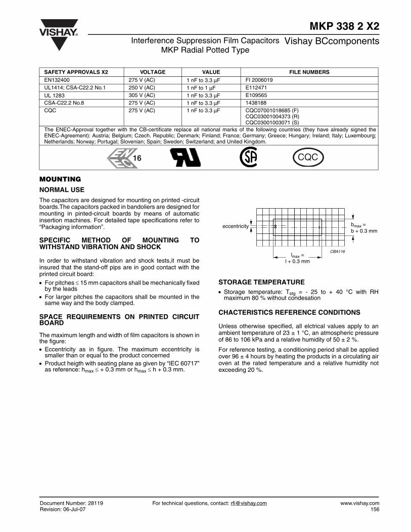
SPACE REQUIREMENTS ON PRINTED CIRCUITBOARD
The maximum length and width of film capacitors is shown inthe figure:• Eccentricity as in figure. The maximum eccentricity is
smaller than or equal to the product concerned• Product heigth with seating plane as given by “IEC 60717”
as reference: hmax ≤ + 0.3 mm or hmax ≤ h + 0.3 mm.
STORAGE TEMPERATURE• Storage temperature: Tstg = - 25 to + 40 °C with RH
maximum 80 % without condesation
CHACTERISTICS REFERENCE CONDITIONS
Unless otherwise specified, all elctrical values apply to anambient temperature of 23 ± 1 °C, an atmospheric pressureof 86 to 106 kPa and a relative humidity of 50 ± 2 %.
For reference testing, a conditioning period shall be appliedover 96 ± 4 hours by heating the products in a circulating airoven at the rated temperature and a relative humidity notexceeding 20 %.
SAFETY APPROVALS X2 VOLTAGE VALUE FILE NUMBERSEN132400 275 V (AC) 1 nF to 3.3 µF FI 2006019UL1414; CSA-C22.2 No.1 250 V (AC) 1 nF to 1 µF E112471
UL 1283 305 V (AC) 1 nF to 3.3 µF E109565CSA-C22.2 No.8 275 V (AC) 1 nF to 3.3 µF 1438188CQC 275 V (AC) 1 nF to 3.3 µF CQC07001018685 (F)
CQC03001004373 (R)CQC03001003071 (S)
The ENEC-Approval together with the CB-certificate replace all national marks of the following countries (they have already signed theENEC-Agreement): Austria; Belgium; Czech. Republic; Denmark; Finland; France; Germany; Greece; Hungary; Ireland; Italy; Luxembourg;Netherlands; Norway; Portugal; Slovenian; Spain; Sweden; Switzerland; and United Kingdom.
bmax = b + 0.3 mm
lmax =l + 0.3 mm
CBA116
eccentricity
CQC16
www.vishay.com For technical questions, contact: [email protected] Document Number: 28119157 Revision: 06-Jul-07
MKP 338 2 X2Vishay BCcomponents Interference Suppression Film Capacitors
MKP Radial Potted Type
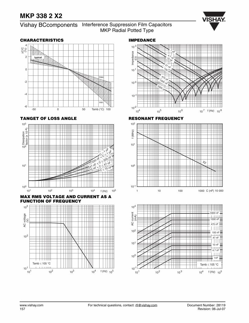
CHARACTERISTICS
TANGET OF LOSS ANGLE
MAX RMS VOLTAGE AND CURRENT AS A FUNCTION OF FREQUENCY
IMPEDANCE
RESONANT FREQUENCY
min.
max.
typical
-50
ΔC/C
(%
)
2
-2
-4
-6
0
0 50 100Tamb (°C)
4
Dis
sipa
tion
fact
or (
x 10
-4)
C > 1 µF
C ≤ 10 nF10 nF < C ≤ 47 nF
47 nF < C ≤ 220 nF
220 nF < C ≤ 1 µF
103
102
101
100
101 102 103 104 105f (Hz)
Tamb ≤ 105 °C
AC
vo
ltag
e
(V)
103
102
101
f (Hz)101 102 103 10410
5
3300 nF
10 nF
47 nF100 nF
470 nF1000 nF
4.7 nF
1 nF
Impe
danc
e
(Ω
)
10 3
10 1
10-2
10 0
f (Hz)10 610410
5 10 7 10 8
10-1
X2
102
101
100
10-1
1 10 100 1000 10 000
f (M
Hz)
C (nF)
470 nF
100 nF
47 nF
10 nF
1000 nF
1nF
3300 nF
4.7 nF
AC
curr
ent
(m
A)
104
102
100
101
f (Hz)101 102 10 3 104 10510-1
Tamb ≤ 105 °C
Document Number: 28119 For technical questions, contact: [email protected] www.vishay.comRevision: 06-Jul-07 158
MKP 338 2 X2Interference Suppression Film Capacitors
MKP Radial Potted TypeVishay BCcomponents
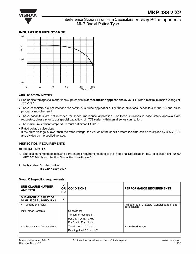
INSULATION RESISTANCE
APPLICATION NOTES• For X2 electromagnetic interference suppression in across the line applications (50/60 Hz) with a maximum mains voltage of
275 V (AC).
• These capacitors are not intended for continuous pulse applications. For these situations, capacitors of the AC and pulseprograms must be used.
• These capacitors are not intended for series impedance application. For these situations in case safety approvals arerequested, please refer to our special capacitors of 1772 series with internal series connection.
• The maximum ambient temperature must not exceed 110 °C.
• Rated voltage pulse slope:If the pulse voltage is lower than the rated voltage, the values of the specific reference data can be multiplied by 385 V (DC)and divided by the applied voltage.
INSPECTION REQUIREMENTS
GENERAL NOTES1. Sub-clause numbers of tests and performance requirements refer to the “Sectional Specification, IEC_publication EN132400
(IEC 60384-14) and Section One of this specification”.
2. In this table: D = destructiveND = non-distructive
Group C inspection requirements
106
105
104
0 20 40 60 80 100Tamb (°C)
RC
(s)
SUB-CLAUSE NUMBER AND TEST
DORND
CONDITIONS PERFORMANCE REQUIREMENTS
SUB-GROUP C1A PART OF SAMPLE OF SUB-GROUP C1
D
4.1 Dimensions (detail) As specified in Chapters “General data” of this specification
Initial measurements Capacitance
Tangent of loss angle:
For C ≤ 1 µF at 10 kHz
For C > 1 µF at 1 kHz
4.3 Robustness of terminations Tensile: load 10 N; 10 s
Bending: load 5 N; 4 x 90°
No visible damage

www.vishay.com For technical questions, contact: [email protected] Document Number: 28119159 Revision: 06-Jul-07
MKP 338 2 X2Vishay BCcomponents Interference Suppression Film Capacitors
MKP Radial Potted Type
SUB-CLAUSE NUMBER AND TEST
DORND
CONDITIONS PERFORMANCE REQUIREMENTS
4.4 Resistance to soldering heat No pre-drying
Method: 1A
Solder bath: 280 °C
Duration: 10 s
4.19 Component solvent resistance
Isopropylalcohol at room temperature
Method: 2
Immersion time: 5 ± 0.5 min
Recovery time:
Min 1 hour, max 2 hours
4.4.2 Final measurements Visual examination
Capacitance
Tangent of loss angle
Insulation resistance
No visible damage
Legible marking
¦ΔC/C¦ ≤ 5 % of the value measured initially.
Increase of tan δ:
≤ 0.008 for:
C ≤ 1 µF or
≤ 0.005 for:
C > 1 µF
Compared to values measured initially
As specified in Section “Insulation Resistance” of this specification
SUB-GROUP C1A PART OF SAMPLE OF SUB-GROUP C1
D
Initial measurements Capacitance
Tangent of loss angle:
For C ≤ 1 µF at 10 kHz
For C > 1 µF at 1 kHz
4.20 Solvent resistance of the marking: see Section “General notes”; item 5.
Isopropylalcohol at room temperature
Method: 1
Rubbing material: cotton wool
Immersion time: 5 ± 0.5 min
θA = - 55 °C
No visible damage
Legible marking
4.6 Rapid change of temperature θB = + 110 °C
5 cycles
Duration t = 30 min
4.6.1 Inspection Visual examination No visible damage
4.7 Vibration (see note 3.1) Mounting: see Section “Mounting” of this specification
Procedure B4
Frequency range: 10 to 55 Hz.
Amplitude: 0.75 mm or
Acceleration 98 m/s²
(whichever is less severe)
Total duration 6 hours.
4.7.2 Final inspection Visual examination No visible damage
4.9 Shock (see note 3) Mounting: see Section “Mounting” for more information
Pulse shape: half sine
Acceleration: 490 m/s²
Duration of pulse: 11 ms

Document Number: 28119 For technical questions, contact: [email protected] www.vishay.comRevision: 06-Jul-07 160
MKP 338 2 X2Interference Suppression Film Capacitors
MKP Radial Potted TypeVishay BCcomponents
SUB-CLAUSE NUMBER AND TEST
DORND
CONDITIONS PERFORMANCE REQUIREMENTS
4.9.2 Final measurements Visual examination
CapacitanceTangent of loss angle
Insulation resistance
No visible damage
¦ΔC/C¦ ≤ 5 % of the value measured initially.
Increase of tan δ:
≤ 0.008 for:
C ≤ 1 µF or
≤ 0.005 for:
C > 1 µF
Compared to values measured initially
As specified in Section “Insulation Resistance” of this specification
SUB-GROUP C1 COMBINED SAMPLE OF SPECIMENS OF SUB-GROUPS C1A AND C1B
D
4.11 Climatic sequence
4.11.1 Initial measurements Capacitance
Measured in 4.4.2 and 4.9.2
Tangent of loss angle:
Measured initially in C1A and C1B
Temperature: 110 °C
4.11.2 Dry heat Duration: 16 hours
4.11.3 Damp heat cyclic
Test Db
First cycle Temperature: - 55 °C
4.11.4 Cold Duration: 2 hours
4.11.5 Damp heat cyclic
Test Db
remaining cycles Visual examination No visible damage
4.11.6 Final measurements
Capacitance
Tangent of loss angle
Voltage proof
1200 V (DC); 1 min between term.
Insulation resistance
Legible marking
¦ΔC/C¦ ≤ 5 % of the value measured in 4.11.1.
Increase of tan δ:≤ 0.008 for:
C ≤ 1 µF or
≤ 0.005 for:
C > 1 µF
Compared to values measured in 4.11.1.
No permanent breakdown or flash-over
≥ 50 % of values specified in Section “Insulation resistance” of this specification
SUB GROUP C2 D
4.12 Damp heat steady state 56 days; 40 °C; 90 to 95 % RH
no load
4.12.1 Initial measurements Capacitance
Tangent of loss angle:
For C ≤ 1 µF at 10 kHz or
For C > 1 µF at 1 kHz

www.vishay.com For technical questions, contact: [email protected] Document Number: 28119161 Revision: 06-Jul-07
MKP 338 2 X2Vishay BCcomponents Interference Suppression Film Capacitors
MKP Radial Potted Type
SUB-CLAUSE NUMBER AND TEST
DORND
CONDITIONS PERFORMANCE REQUIREMENTS
4.12.3 Final measurements Visual examination
Capacitance
Tangent of loss angle
Voltage proof
1200 V (DC); 1 min between term.
Insulation resistance
No visible damage
Legible marking
¦ΔC/C¦ ≤ 5 % of the value measured in 4.12.1.
Increase of tan δ:
≤ 0. 008 for:
C ≤ 1 µF or
≤ 0. 005 for:
C > 1 µF
Compared to values measured in 4.12.1.
No permanent breakdown or flash-over
≥ 50 % of values specified in Section “Insulation resistance” of this specification
SUB-GROUP C3 D
4.13.1 Initial measurements Capacitance
Tangent of loss angle:
For C ≤ 1 µF at 10 kHz
For C > 1 µF at 1 kHz
4.13 Impulse voltage 3 successive impulses, full wave, peak voltage:
X2: 2.5 kV for C ≤ 1 µF
X2: 2.5 kV/√C for C > 1 µF
Max.24 pulses
No selfhealing breakdowns or flashover
4.14 Endurance Duration: 1000 h
1.25 x URac at 110 °C
Once in every hour the voltage is increased to
1000 V (RMS) for 0.1 s via resistor of 47 Ω ± 5 %
4.14.7 Final measurements Visual examination
Capacitance
Tangent of loss angle
Voltage proof
1200 V (DC); 1 min between
terminations.
2050 V (DC); 1 min between
terminations and case.
Insulation resistance
No visible damage
Legible marking
¦ΔC/C¦ ≤ 10 % compared to values measured in 4.13.1.
Increase of tan δ:
≤ 0.008 for:
C ≤ 1 µF or
≤ 0.005 for:
C > 1 µF
Compared to values measured in 4.13.1.
No permanent breakdown or flash-over
≥ 50 % of values specified in Section “Insulation
resistance” of this specification

Document Number: 28119 For technical questions, contact: [email protected] www.vishay.comRevision: 06-Jul-07 162
MKP 338 2 X2Interference Suppression Film Capacitors
MKP Radial Potted TypeVishay BCcomponents
SUB-CLAUSE NUMBER AND TEST
DORND
CONDITIONS PERFORMANCE REQUIREMENTS
SUB-GROUP C4 D
4.15 Charge and discharge10 000 cycles (50 c/s) charge to UR half sinewave Duration: 5 msDischarge resistance:
Rmin = 2.2 Ω
4.15.1 Initial measurements Capacitance
Tangent of loss angle:
For C ≤ 1 µF at 10 kHz
For C > 1 µF at 1 kHz
4.15.3 Final measurements Capacitance
Tangent of loss angle
Insulation resistance
¦ΔC/C¦ ≤ 10 % compared to values measured in 4.15.1.
Increase of tan δ:
≤ 0.008 for:
C ≤ 1 µF or
≤ 0.005 for:
C > 1 µF
Compared to values measured in 4.15.1.
≥ 50 % of values specified in Section “Insulation resistance” of this specification
SUB-GROUP C5 D
4.16 Radio frequency characteristic
Resonance frequency As specified in Section “Resonant frequency” of this specification. ± 10 %
SUB-GROUP C6 D
4.17 Passive flammability
Class BBore of gas jet: Ø 0.5 mmFuel: butaneTest duration for actual volume V in mm³:V . 250: 10 s250 < V . 500: 20 s500 < V . 1750: 30 sV > 1750: 60 sOne flame application
After removing test flame from capacitor, the capacitor must not continue to burn for more than 10 s. No burning particle must drop from the sample.
SUB-GROUP C7
4.18 Active flammability 20 x 2.5 kV discharges on the test capacitor connected to URac
The cheese cloth around the capacitors shall not burn with a flame.
No electrical measurements are required.
R 385 Vdc1.5 C dU dt⁄( )×--------------------------------------------=
Document Number: 91000 www.vishay.comRevision: 18-Jul-08 1
Disclaimer
Legal Disclaimer NoticeVishay
All product specifications and data are subject to change without notice.
Vishay Intertechnology, Inc., its affiliates, agents, and employees, and all persons acting on its or their behalf(collectively, “Vishay”), disclaim any and all liability for any errors, inaccuracies or incompleteness contained hereinor in any other disclosure relating to any product.
Vishay disclaims any and all liability arising out of the use or application of any product described herein or of anyinformation provided herein to the maximum extent permitted by law. The product specifications do not expand orotherwise modify Vishay’s terms and conditions of purchase, including but not limited to the warranty expressedtherein, which apply to these products.
No license, express or implied, by estoppel or otherwise, to any intellectual property rights is granted by thisdocument or by any conduct of Vishay.
The products shown herein are not designed for use in medical, life-saving, or life-sustaining applications unlessotherwise expressly indicated. Customers using or selling Vishay products not expressly indicated for use in suchapplications do so entirely at their own risk and agree to fully indemnify Vishay for any damages arising or resultingfrom such use or sale. Please contact authorized Vishay personnel to obtain written terms and conditions regardingproducts designed for such applications.
Product names and markings noted herein may be trademarks of their respective owners.