
Interfacing the Clinical Laboratory: A Primer for LIS … the Clinical Laboratory: A Primer for LIS...
25
© 1996, Med TechNet Presentations October 1996 Page 1 Med TechNet Online Services East Amherst, NY October 7 - November 4, 1996 Interfacing the Clinical Laboratory: A Primer for LIS Managers John Selmyer and Bruce Cloutier Dawning Technologies, Inc. A t a glance ... Introduction .................................... 2 Basic Considerations ............................. 2 Clinical analyzer variables .................. 3 Functional Types ................................ 4 Unidirectional applications .................. 4 Bi-directional applications .................. 4 Broadcast bi-directional applications .......... 5 Query mode bi-directional applications ......... 5 Interface architecture ............................. 6 Straight-in, software-only interfaces ........... 6 Black box interfaces ....................... 7 PC-based software interfaces ................ 7 Intelligent intermediate devices ............... 8 Other intermediate devices .................. 8 Inside the Interface .............................. 9 The Physical Layer: Making the Connection .... 10 The Data-Link Layer: Moving the Information ... 11 The Network Layer: Identifying the Source ..... 12 The Transport Layer: Understanding the Flow .. 12 The Transport Layer: Getting the Message Across .............................. 13 The Presentation Layer: Understanding the Message .............................. 15 The Application Layer: Getting the Job Done ... 16 Interface Communication Standards ................ 16 Background - the need for standards ......... 16 Standards structure ...................... 17 The ASTM standard ...................... 17 Common Data Format .................... 18 The HL-7 Standard ....................... 18 The IEEE MIB effort ...................... 18 Planning for Instrument Interfaces .................. 18 Interfacing instruments currently in the laboratory. .............................. 18 Data buffering........................... 18 Bi-directional Interfaces ................... 19 Operation of interfaces .................... 19 Integration with other LIS functions .......... 19 Unusual or custom interfaces ............... 19 Future instrument selections and upgrades .... 19 Costs ................................. 19 Reliability .............................. 20 Physical layout of the laboratory ............. 20 Vendor support ......................... 20 LIS Upgrading .......................... 20 Interface Validation Procedures ............. 20 Interface System Validation ....................... 21 Regulatory background ................... 21 The validation plan ....................... 21 Incorporating instrument interfaces into the validation plan ........................... 21 Validation testing ........................ 21 Installation Qualification ................... 21 Process Performance Qualification ........... 22 Product Performance Qualification ........... 22 Analysis and review ...................... 22 Acceptance ............................ 22 Revalidation ............................ 22 Onsite Personnel Requirements .................... 23 Common problems with interfacing ................. 23 Inadequate instrument specifications ......... 23 Familiarity with instrument operation and configuration .................... 23 Sufficient time for implementation ........... 23 New instrument interfaces ................. 23 Future Considerations ........................... 24 Summary ..................................... 24 User control ............................ 24 Options for Users ........................ 25 References ................................... 25
Transcript of Interfacing the Clinical Laboratory: A Primer for LIS … the Clinical Laboratory: A Primer for LIS...

© 1996, Med TechNet Presentations October 1996 Page 1
Med TechNet Online Services East Amherst, NY October 7 - November 4, 1996
Interfacing the Clinical Laboratory: A Primer for LIS Managers
John Selmyer and Bruce CloutierDawning Technologies, Inc.
At a glance ...Introduction . . . . . . . . . . . . . . . . . . . . . . . . . . . . . . . . . . . . 2
Basic Considerations . . . . . . . . . . . . . . . . . . . . . . . . . . . . . 2Clinical analyzer variables . . . . . . . . . . . . . . . . . . 3
Functional Types . . . . . . . . . . . . . . . . . . . . . . . . . . . . . . . . 4Unidirectional applications . . . . . . . . . . . . . . . . . . 4Bi-directional applications . . . . . . . . . . . . . . . . . . 4Broadcast bi-directional applications . . . . . . . . . . 5Query mode bi-directional applications . . . . . . . . . 5
Interface architecture . . . . . . . . . . . . . . . . . . . . . . . . . . . . . 6Straight-in, software-only interfaces . . . . . . . . . . . 6Black box interfaces . . . . . . . . . . . . . . . . . . . . . . . 7PC-based software interfaces . . . . . . . . . . . . . . . . 7Intelligent intermediate devices . . . . . . . . . . . . . . . 8Other intermediate devices . . . . . . . . . . . . . . . . . . 8
Inside the Interface . . . . . . . . . . . . . . . . . . . . . . . . . . . . . . 9The Physical Layer: Making the Connection . . . . 10The Data-Link Layer: Moving the Information . . . 11The Network Layer: Identifying the Source . . . . . 12The Transport Layer: Understanding the Flow . . 12The Transport Layer: Getting the Message Across
. . . . . . . . . . . . . . . . . . . . . . . . . . . . . . 13The Presentation Layer: Understanding the Message
. . . . . . . . . . . . . . . . . . . . . . . . . . . . . . 15The Application Layer: Getting the Job Done . . . 16
Interface Communication Standards . . . . . . . . . . . . . . . . 16Background - the need for standards . . . . . . . . . 16Standards structure . . . . . . . . . . . . . . . . . . . . . . 17The ASTM standard . . . . . . . . . . . . . . . . . . . . . . 17Common Data Format . . . . . . . . . . . . . . . . . . . . 18The HL-7 Standard . . . . . . . . . . . . . . . . . . . . . . . 18The IEEE MIB effort . . . . . . . . . . . . . . . . . . . . . . 18
Planning for Instrument Interfaces . . . . . . . . . . . . . . . . . . 18
Interfacing instruments currently in the laboratory.. . . . . . . . . . . . . . . . . . . . . . . . . . . . . . 18
Data buffering. . . . . . . . . . . . . . . . . . . . . . . . . . . 18Bi-directional Interfaces . . . . . . . . . . . . . . . . . . . 19Operation of interfaces . . . . . . . . . . . . . . . . . . . . 19Integration with other LIS functions . . . . . . . . . . 19Unusual or custom interfaces . . . . . . . . . . . . . . . 19Future instrument selections and upgrades . . . . 19Costs . . . . . . . . . . . . . . . . . . . . . . . . . . . . . . . . . 19Reliability . . . . . . . . . . . . . . . . . . . . . . . . . . . . . . 20Physical layout of the laboratory . . . . . . . . . . . . . 20Vendor support . . . . . . . . . . . . . . . . . . . . . . . . . 20LIS Upgrading . . . . . . . . . . . . . . . . . . . . . . . . . . 20Interface Validation Procedures . . . . . . . . . . . . . 20
Interface System Validation . . . . . . . . . . . . . . . . . . . . . . . 21Regulatory background . . . . . . . . . . . . . . . . . . . 21The validation plan . . . . . . . . . . . . . . . . . . . . . . . 21Incorporating instrument interfaces into the validation
plan . . . . . . . . . . . . . . . . . . . . . . . . . . . 21Validation testing . . . . . . . . . . . . . . . . . . . . . . . . 21Installation Qualification . . . . . . . . . . . . . . . . . . . 21Process Performance Qualification . . . . . . . . . . . 22Product Performance Qualification . . . . . . . . . . . 22Analysis and review . . . . . . . . . . . . . . . . . . . . . . 22Acceptance . . . . . . . . . . . . . . . . . . . . . . . . . . . . 22Revalidation . . . . . . . . . . . . . . . . . . . . . . . . . . . . 22
Onsite Personnel Requirements . . . . . . . . . . . . . . . . . . . . 23
Common problems with interfacing . . . . . . . . . . . . . . . . . 23Inadequate instrument specifications . . . . . . . . . 23Familiarity with instrument operation and
configuration . . . . . . . . . . . . . . . . . . . . 23Sufficient time for implementation . . . . . . . . . . . 23New instrument interfaces . . . . . . . . . . . . . . . . . 23
Future Considerations . . . . . . . . . . . . . . . . . . . . . . . . . . . 24
Summary . . . . . . . . . . . . . . . . . . . . . . . . . . . . . . . . . . . . . 24User control . . . . . . . . . . . . . . . . . . . . . . . . . . . . 24Options for Users . . . . . . . . . . . . . . . . . . . . . . . . 25
References . . . . . . . . . . . . . . . . . . . . . . . . . . . . . . . . . . . 25
Med TechNet Tip
Click on "At a Glance" topics to move quickly to a subject. Use the "magnifying glass" for closer looks at figures.

Interfacing the Clinical Laboratory J. Selmyer & B. Cloutier
© 1996, Med TechNet Presentations October 1996 Page 2
IntroductionThe contemporary clinical laboratory is a productionenvironment that requires the coordination of many people,automated analytical instruments, patient specimens, suppliesand procedures. The clinical laboratory is essentially in theinformation business, responsible for translating physicianorders into test result reports. Each step in laboratoryoperations generates data affecting the information sought:tracking patients from whom specimens are to be obtained,identifying specimen containers at the bedside, assigningidentification (ID) numbers to specimens received in thelaboratory, preparing and identifying specimen aliquots fordistribution to laboratory workstations, programminginstrumentation to perform to ordered determinations,matching test results with specimen IDs, assembling collatedreports for each patient specimen, and so on. The tremendousvolume of data processed by the clinical laboratory has longbeen a source of concerns and problems to be overcome.
The business of operating a clinical laboratory has changeddramatically in recent years, in response to changes in marketforces. The factors influencing current clinical laboratoriesinclude the charter of providing vital services (information) tothe clinical staff, pressure to report this information ASAP,pressure to combine accuracy and precision with speed,economic constraints on staff resources, continuing pressureto define and reduce capital and operational costs, increasingregulatory requirements, the transition of the hospitallaboratory from a profit center to a cost center under changingreimbursement guidelines, and the need to process billinginformation expeditiously. The current political environmentpromises to deliver additional pressures under the label ofhealthcare reform. An instrument interface is an automatic, electronic connection
It has long been recognized that the clinical laboratory is a exchange of information. A functional instrument interfaceprimary generator of data transactions within the hospital may be viewed as a state of equilibrium across a number ofenvironment. Even early capacity studies indicated that the influencing factors, as discussed below.laboratory is responsible for 45% - 60% of the total number oftransactions. Advances in laboratory technology, whileimproving analytical instrumentation and techniques, have notaltered the fundamental transaction intensive environment ofthe clinical laboratory.
Traditional paper based laboratory data processing systemsare slow, labor intensive, error prone and do not help meetchanging regulatory reporting requirements. Paper basedreporting systems generally are not adequate in the face ofcurrent clinical and business pressures.
One common remedy to these influencing forces is theimplementation of a laboratory information system (LIS). Intheory, an LIS can dramatically reduce the clerical laborrequired to handle information, increase accuracy of patientreports, and significantly speed their production andavailability to the clinical staff. An LIS should also be ofconsiderable help in analyzing the quality of patient test resultinformation and in producing records compliant withregulatory requirements.
The extent to which an LIS achieves these general objectivesis the sum of many elements of hardware and software, often
from multiple sources. An interface to a hospital informationsystem (HIS) can provide an efficient means of downloadingpatient demographics and order entry information anduploading completed patient reports. LIS software provides forassignment of specimen IDs and creation of worklists for thevarious laboratory workstations. Test results are produced bythe array of clinical analyzers, which must be captured by theLIS. Once result information is in the LIS it can bemanipulated according to range and delta check limits,reviewed, and verified prior to release. Completed patientreports are then printed and/or transmitted back to an HIS fordistribution to the patient location.
The majority of information managed by the LIS is test resultdata generated by clinical analyzers. For this reason, theconnection of automated instruments on-line to the LIS isperhaps the most important element of the system. Withoutavailable, functional, reliable instrument interface connections,the LIS would have little information to manage.
Fortunately, nearly all popular clinical instruments are capableof being interfaced to an LIS. The availability of acommunication port on the analyzer is not, however, aguarantee of an easily established, affordable, or properlyfunctioning interface to the LIS.
This paper addresses the clinical instrument interface processincluding methods, considerations and alternatives thatlaboratory personnel should be aware of when selecting,contracting for or developing an LIS.
Basic Considerations
between analyzer and computer for the rapid, accurate
1. Physical (a) The instrument must be equippedwith an active input/output port to which computer devicesmay be connected. On most contemporary clinical analyzers,this is a serial asynchronous RS-232 port. (b) The hostsystem must have a corresponding I/O port available. (c) Aconnection cable is required, from the analyzer to an interfacedevice or the host system connection point.
2. Hardware Many instruments include a personalcomputer (PC) or some other form of data managementsystem (DMS) as an integral part of the analyzer. These DMSdevices are typically used to provide data reduction, control ofmultiple instruments, reporting capability and/or QC datahandling. In most cases in which some form of DMS ispresent, the interface connection is made to the DMS ratherthan to the analyzer itself.
Intermediate devices may be used in between the analyzerconnection and the host system connection point, to providedistributed processing, data buffering, reformatting,networking or other control over interface communications. These devices include specialized interface workstations, PCsequipped with interface boards, user programmed PCs, black

Interfacing the Clinical Laboratory J. Selmyer & B. Cloutier
© 1996, Med TechNet Presentations October 1996 Page 3
box interfaces, and simple buffer boxes. A primary problem in connecting clinical instrumentation to
Host systems are available on many hardware platforms, data formats and communication protocols produced byranging from single user PC stations to large mainframes. analyzers. Clinical instruments exhibit as many variances inMost contemporary LIS products are multi-user systems their ability to communicate with an information system aswhich run on minicomputers or PC networks. they exhibit physically and operationally. This chaotic
3. Software The main categories of host systemsoftware are operating system software and applicationsoftware. Operating system software controls basic machinefunctions such as interaction with I/O devices, memorymanagement, disk access, and creating the applicationsoftware environment. Operating system software is typicallyprovided by a hardware manufacturer or a third party. Examples are MS-DOS and Windows (Microsoft Corp.,Redmond, WA), PC-DOS (IBM Corporation, Armonk, NY),UNIX (AT&T Bell Laboratories, Murray Hill, NJ), VMS (DigitalEquipment Company, Marlboro, MA) and OS/400 (IBMCorporation, Armonk, NY). Application software is theprincipal product of the LIS vendor, and provides all of the"user visible" LIS features. Application software may bewritten in a number of programming languages includingC/C++, BASIC, MUMPS, COBOL, Fortran and Pascal.
The host system application software must include modulesto control communication with the analyzer, according to theanalyzer's format and protocol specifications. In applicationsin which an intermediate device is used, the intermediatedevice must contain software to similarly control analyzercommunications. The host must then contain software tocontrol communication with the intermediate device, whichmay be different than interacting directly with the analyzer.
The equilibrium of a running instrument interface can bedisturbed by alterations to any of the above elements, fromthe obvious, of a broken connection cable, to the not soobvious, of a minor change to instrument output.
Clinical analyzer variables
There are currently many types and manufacturers of clinicalanalyzers available. The wide variety of popular clinicalanalyzers exhibit many operational, functional, and otherdifferences. These instruments have evolved, driven bymarket forces that include new measurement technologiesbecoming available; improved productivity; changingregulatory and reimbursement environments; costs ofacquisition; operation and maintenance; reliability; accuracyand precision; size; ease of use; reporting capabilities; andability to connect to an information system.
Analyzers capable of being interfaced to an LIS are found inall areas of the clinical laboratory: chemistry, hematology,urinalysis, toxicology, immunoassay, coagulation,microbiology, blood gas, and special chemistry. Nearly all ofthe routine clinical instruments are equipped with a serial RS-232 I/O port. Many of the new point of care analyzers alsoprovide some means of storing data for later upload to an LIS. Typically, instruments to be interfaced are prioritized bytesting volume, placing chemistry and hematologyinstruments at the top of the list.
information systems is the lack of effective standardization of
communication environment has resulted in substantialrewriting of host resident interface software with each newinstrument, leading to increased cost to the consumer andlonger development times, affecting availability.
Efforts to address the lack of instrument communicationstandards have taken several forms. A few analyzermanufacturers have attempted to provide a common interfaceformat across several of their instrument models. Severalindependent companies have developed intermediateinterface devices that reformat analyzer output into a morestandard format across many instruments. More recentlysome industry organizations (ASTM, HL-7, IEEE, etc.) haveled efforts to define communication standards for medicaldevices, including clinical analyzers. A more completediscussion of these standardization efforts is provided later inthis paper.
In spite of sporadic efforts to standardize communication withclinical analyzers, most analyzers are quite different in theircommunication specifications from one to another. In fact,even the physical connection of a cable to the instrumentoften varies from one instrument to another. Over 30 differentcable configurations are required to handle currently popularanalyzers, due to physical differences in connector type, size,sex and PIN definitions.
A related problem to be overcome is the wide variety in qualityof analyzer manufacturers' interface specification documents. An interface specification must contain three forms ofinformation: 1) a definition of the physical connection point onthe analyzer, to allow a connection cable to be built; 2)specifications of the communication protocol required tocommunicate with the analyzer; and 3) a clear description ofthe data format produced, including examples of data outputin all modes of instrument operation. This must includespecification of multiple formats if the instrument is capable ofmore than one. Various flag conditions and definitions mustbe included. Download format and protocol for bi-directionalapplications must be defined.
Highly desirable in the interface specification is a discussionof default switch settings, baud rates and other informationnecessary to establish a functional interface. It is helpful toknow how to access interface related configuration screens ormodes on the analyzer to check appropriate settings or makechanges.
The expense of interfacing a number of analyzers has in somecases been higher than it should have been due to difficulty inobtaining the necessary information. Common problemsfound in analyzer interface specification documents include nospecification of the connection port other than RS-232,reference to the data format in indirect terms (identical to thatproduced on the printer), incomplete specification of recordoutput types, or simply inaccurate information (documentationdoes not match analyzer output). Some analyzer interface

Interfacing the Clinical Laboratory J. Selmyer & B. Cloutier
© 1996, Med TechNet Presentations October 1996 Page 4
Figure 1: A Unidirectional Interface
Figure 2: A Bi-Directional Interface
specifications have been massive documents, with manypages devoted to irrelevant information (defining the RS-232standard at length), while declining to include importantdetails (connector descriptions necessary to build a cable).
A last obstacle to mention is the lack of stability of analyzerinterface specifications. The role of software in theoperational control of a clinical instrument has beenincreasing with advances in microprocessors and relatedelectronic technology. Instrument software controls internaloperation of the analyzer, user interaction and communicationwith the LIS. Occasionally, instrument operating software isupdated to fix bugs or add enhancements compared to earliersoftware versions. A regularly occurring circumstance inclinical laboratories is the installation of new instrumentsoftware that in some way modifies communication with theLIS. This sudden (usually unexpected) alteration in instrument
output often results in interface failure, and may requiremodification of the LIS or other software to resolve.
These inconsistencies of analyzer output and other relatedcharacteristics have profound implications for the LIS, byforcing the LIS or other device connected to the analyzer tocontain software specifically written to handlecommunications with that individual analyzer. With eachanalyzer requiring unique LIS or interface software, manyprogrammers have been kept busy reinventinginstrument interfaces. This situation contributesdirectly to the cost and availability of interfaceapplications, ultimately borne by the end user.
Functional Types
Unidirectional applications
The traditional type of instrument interface is aunidirectional application: the instrument performsits test and transmits results to the interfacedevice/host system in one direction only (upload). Many instruments have been limited by design tounidirectional interfaces. These analyzers are generally singletest, batch or profile testing instruments in which the array oftests performed does not vary from specimen to specimen.
A unidirectional interface (see Figure 1) does not mean thereis no communication at all coming down from the host orinterface device to the analyzer. Most instruments requiresome form of handshaking (communication protocol) and/orerror checking to obtain data records. Failure of the host orinterface device to meet these protocol requirements will oftencause the instrument to cease operation.
The data record transmitted (uploaded) from the analyzergenerally includes the specimen ID, the array of test names,and results. Additional fields may include a variety of flagcondition indicators, specimen type (blood, urine, STAT,control material), error check characters, and/or somedemographic information among others.
A more unusual unidirectional application is one in which thecommunication is downloaded from the host only, with no test
result upload. This situation occurs withcertain autoloader devices, which accepta host download for control of loadingspecimens and reagents into microplatesor other special containers. Thespecimen/reagent containers are thenmoved to a separate instrument foranalysis.
Bi-directional applications
A bi-directional interface (see Figure 2)involves true two-way communicationbetween the analyzer and interface/host. The host downloads specimen ID and
test order information; the analyzer uploads specimen ID andtest result information. Support of bi-directional interfacecapability is most generally found on random access testinginstruments, which can perform a different array of tests oneach successive specimen.
Historically, most random access testing instruments havebeen chemistry analyzers. More recently, bi-directionalinterface capability has been incorporated into many
microbiology, immunoassay, coagulation and somehematology instruments. Not all of these instruments providerandom access testing flexibility.
A bi-directional interface application saves the technologistthe time to program test orders into the analyzer, and

Interfacing the Clinical Laboratory J. Selmyer & B. Cloutier
© 1996, Med TechNet Presentations October 1996 Page 5
Figure 3: Query Bi-Directional Interface
eliminates manual entry errors. This can result in a memory becomes full, and the analyzer will likely halt LISconsiderable improvement in analyzer productivity in a busy communications. The memory cleanup usually requires alllaboratory. Newer random access testing, bidirectionally the analyzers in the array to complete processing of all loadedinterfaced analyzers will also incorporate bar code specimen specimens, transmit all result information back to the LIS,label scanning which provides automatic positive specimen ID then stop for the cleanup procedure.capability. This can eliminate manual entry of specimen IDsand/or coding of specimens by tray/cup position. Download memory cleanup is a particular problem for busy
Some instruments support a bi-directional interface yet This makes it difficult or impossible to identify a time when allremain profile testing analyzers may beinstruments. It is possible to interrupted long enoughdownload patient to perform the cleanupdemographic information to procedure. A separatethese instruments, which may problem sometimesbe useful if special reports are encountered is that theprinted from the analyzer analyzer may require aDMS. If reports are not being cumbersome procedureprinted from these to do the memoryinstruments, a bi-directional cleanup, which can beinterface may be of limited frustrating.use and considerable extracost. Large-frame Broadcast bi-directionalhematology analyzers fall into applications can bethis category. simplified with the
While most instruments support a bi-directional interface on (discussed in Part 2 of this article). An intermediate interfaceone serial I/O port, there are several instrument models which device can assist the host system by controlling the broadcastuse two ports for a bi-directional application (one port download, and networking the analyzer communications fromuploads, one downloads). This hardware requirement can multiple analyzers to a single port. In some cases, andouble interface-related expenses (two interface devices, two intermediate device can automatically generate a blankhost ports, two versions of host interface software, double download to other instruments in the array once an uploadcabling). Users should explore these analyzer requirements record has been received from one of the analyzers, solvingbefore determining a preferred method of interfacing. the memory cleanup problem.
Broadcast bi-directional applications Query mode bi-directional applications
The trend in major chemistry analyzers in recent years hasbeen to purchase multiple medium-volume instruments asopposed to one high volume instrument. These instrumentsthen constitute an array across which the workload isdistributed. Virtually all contemporary chemistry analyzersare random access testing devices that support bi-directionalinterfaces. A broadcast bi-directional provides a distributeddownload, where all of the download information is sent to allof the analyzers in the array.
The main advantages of the broadcast arrangement is thatthe technologist may load any specimen on any analyzer andbe ensured that the proper download information is available(to process the specimen). This allows the workload to bemore evenly distributed across the analyzer array, withadjustments made as specimen processing continues.
The main disadvantage of broadcast bi-directionals is thatthey create a download memory cleanup issue. If eachanalyzer received the total download information and onlyprocesses a fraction of the workload, some (perhaps themajority) of download information will represent specimensrun on other analyzers in the array. This unused downloadinformation must be erased on each analyzer at the end of ashift or other logical stopping point. Otherwise, instrument
laboratories, where the flow of specimens never really stops.
addition of intelligent intermediate interface devices
In a query mode bi-directional application (see Figure 3), theanalyzer is loaded with bar code labeled specimens. As theanalyzer processes a specimen, the bar code label is scannedand the specimen ID read. The analyzer then generates aquery to the host, requesting download of the associated testorder information. The host responds by looking up thespecimen ID in its database, and generating the appropriatedownload. Query mode bi-directionals are generally an optionon bar code scanner equipped analyzers.
Query mode bi-directional capability is generally perceived asthe solution to the memory cleanup problems inherent tobroadcast bi-directionals, although query mode interactionwas implemented by some clinical analyzers before thoseproblems were well known. A query mode interface ensuresthat each analyzer will only receive download information forthe specimens actually processed at that station, even incases where multiple similar instruments are involved. Memory cleanup of excess downloads is not an issue, andany specimen can still be loaded onto any analyzer.
While solving the memory cleanup concern, query mode bi-directional applications have created other problems, mostly
Interfacing the Clinical Laboratory J. Selmyer & B. Cloutier
© 1996, Med TechNet Presentations October 1996 Page 6
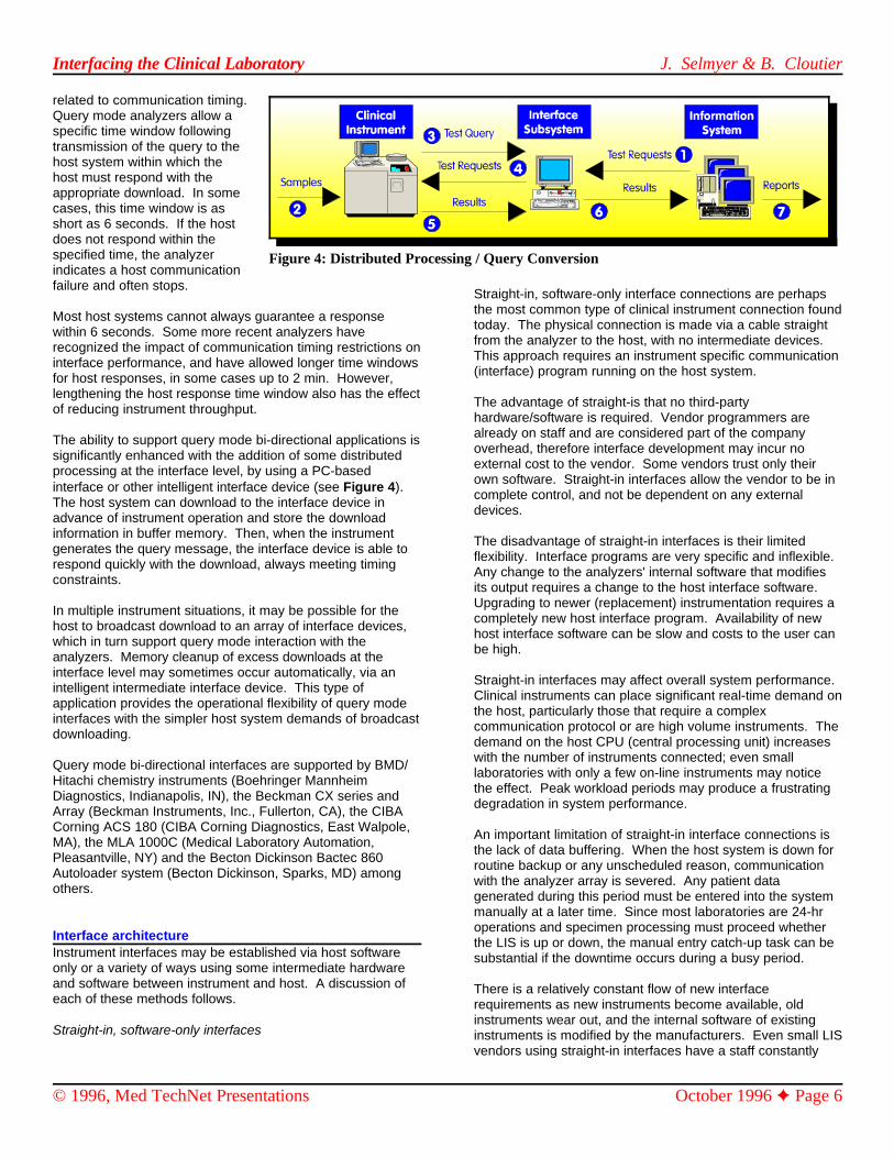
Figure 4: Distributed Processing / Query Conversion
related to communication timing. Query mode analyzers allow aspecific time window followingtransmission of the query to thehost system within which thehost must respond with theappropriate download. In somecases, this time window is asshort as 6 seconds. If the hostdoes not respond within thespecified time, the analyzerindicates a host communicationfailure and often stops.
Most host systems cannot always guarantee a responsewithin 6 seconds. Some more recent analyzers haverecognized the impact of communication timing restrictions oninterface performance, and have allowed longer time windowsfor host responses, in some cases up to 2 min. However,lengthening the host response time window also has the effectof reducing instrument throughput.
The ability to support query mode bi-directional applications issignificantly enhanced with the addition of some distributedprocessing at the interface level, by using a PC-basedinterface or other intelligent interface device (see Figure 4). The host system can download to the interface device inadvance of instrument operation and store the downloadinformation in buffer memory. Then, when the instrumentgenerates the query message, the interface device is able torespond quickly with the download, always meeting timingconstraints.
In multiple instrument situations, it may be possible for thehost to broadcast download to an array of interface devices,which in turn support query mode interaction with theanalyzers. Memory cleanup of excess downloads at theinterface level may sometimes occur automatically, via anintelligent intermediate interface device. This type ofapplication provides the operational flexibility of query modeinterfaces with the simpler host system demands of broadcastdownloading.
Query mode bi-directional interfaces are supported by BMD/Hitachi chemistry instruments (Boehringer MannheimDiagnostics, Indianapolis, IN), the Beckman CX series andArray (Beckman Instruments, Inc., Fullerton, CA), the CIBACorning ACS 180 (CIBA Corning Diagnostics, East Walpole,MA), the MLA 1000C (Medical Laboratory Automation,Pleasantville, NY) and the Becton Dickinson Bactec 860Autoloader system (Becton Dickinson, Sparks, MD) amongothers.
Interface architectureInstrument interfaces may be established via host softwareonly or a variety of ways using some intermediate hardwareand software between instrument and host. A discussion ofeach of these methods follows.
Straight-in, software-only interfaces
Straight-in, software-only interface connections are perhapsthe most common type of clinical instrument connection foundtoday. The physical connection is made via a cable straightfrom the analyzer to the host, with no intermediate devices. This approach requires an instrument specific communication(interface) program running on the host system.
The advantage of straight-is that no third-partyhardware/software is required. Vendor programmers arealready on staff and are considered part of the companyoverhead, therefore interface development may incur noexternal cost to the vendor. Some vendors trust only theirown software. Straight-in interfaces allow the vendor to be incomplete control, and not be dependent on any externaldevices.
The disadvantage of straight-in interfaces is their limitedflexibility. Interface programs are very specific and inflexible. Any change to the analyzers' internal software that modifiesits output requires a change to the host interface software. Upgrading to newer (replacement) instrumentation requires acompletely new host interface program. Availability of newhost interface software can be slow and costs to the user canbe high.
Straight-in interfaces may affect overall system performance. Clinical instruments can place significant real-time demand onthe host, particularly those that require a complexcommunication protocol or are high volume instruments. Thedemand on the host CPU (central processing unit) increaseswith the number of instruments connected; even smalllaboratories with only a few on-line instruments may noticethe effect. Peak workload periods may produce a frustratingdegradation in system performance.
An important limitation of straight-in interface connections isthe lack of data buffering. When the host system is down forroutine backup or any unscheduled reason, communicationwith the analyzer array is severed. Any patient datagenerated during this period must be entered into the systemmanually at a later time. Since most laboratories are 24-hroperations and specimen processing must proceed whetherthe LIS is up or down, the manual entry catch-up task can besubstantial if the downtime occurs during a busy period.
There is a relatively constant flow of new interfacerequirements as new instruments become available, oldinstruments wear out, and the internal software of existinginstruments is modified by the manufacturers. Even small LISvendors using straight-in interfaces have a staff constantly

Interfacing the Clinical Laboratory J. Selmyer & B. Cloutier
© 1996, Med TechNet Presentations October 1996 Page 7
busy with interface development. This can distract from Black box interfaces are relatively expensive (in the $ 1500 - $development of core system features. 4000 range) and have limited bi-directional capability. These
Examples of some vendors routinely using the straight-in users from being sure of interface status during operation. interface approach are Meditech (Medical Information Black box interfaces often become disposable whenTechnology, Inc., Westwood, MA), Cerner Corporation instrumentation is replaced, because they are hard coded for(Kansas City, MO) and Citation Computer Systems, Inc. individual instrument models. All of these factors contribute(Maryland Heights, MO). to the uneasiness of some LIS vendors to incorporate such
Black box interfaces
Many of the instrument interfaces in early laboratory systemswere handled via black box devices between the analyzer andLIS. Black box interface connections were more commonseveral years ago when the need for signal conversion(analog to digital, parallel to serial) from analyzers was amore frequent requirement. Black box interfaces were the firstintermediate devices to provide data buffering, specimen IDentry and limited reformatting. They were also the firstdevices to provide a distributed processing approach toinstrument interfaces. Black box interfaces specifically forclinical instruments were manufactured by Creative Computer The rapidly decreasing cost and increasing performance ofApplications (CCA) (Calabassas, CA), Edmac (Fishers, NY) microcomputers in recent years has made the PC basedand Biovation, Inc. (Richmond, CA). Only CCA remains in instrument interface more attractive both for LIS vendors andthe interface business. home grown systems. This approach uses a PC to interact
Black box interfaces provided several advantages. Their buffering and possibly some reformatting before transmittingsignal conversion capabilities were required to interface some information to the host system.old but very popular analyzers, including the Technicon SMAseries (Miles Inc., Diagnostics Div., Tarrytown, NY) and PC based software interfaces have some advantages overCoulter S and S/Sr. (Coulter Corp., Miami, FL) instruments. black box devices and straight-in interfaces. The PC providesSeveral models of black box interfaces provided some data a distributed processing architecture, decreasing processingbuffering between analyzer and host, allowing the instruments demands on the host system CPU and generally allowing theto be operated during periods of host downtime. Later black system to run faster. A PC with a hard drive can providebox variants provided a keyboard for entry of specimen IDs, substantial data buffering for clinical analyzers, allowingproviding some positive specimen ID for non-keyboard operation during periods of host system downtime. It may beequipped analyzers. easier to develop the instrument specific software at the PC
Another feature introduced by black box interfaces was theautomatic attachment of a short header to the analyzer data More elegant implementations of PC based interfaces mayrecord format. This header was identical across analyzers, add such features as substantial reformatting of data records,and included specimen ID, instrument identifier and other range checking, terminal emulation, access to related data. related information. The concept was that the LIS would Such devices are discussed in the next section.recognize the header as instrument data and more easilyprocess the record. Black box devices do standardize host The disadvantages of PC software interfaces are related tosystem cable connections and communication protocol the software base of the approach. Most PC softwarerequirements, which help simplify instrument connections. interfaces will support only one analyzer, due to the limited
The disadvantages of black box interfaces are numerous. The software development. Flexibility of the PC software interfacemajor disadvantage is that while these products do provide is quite limited, and controlled by the LIS vendor or systemthe system programmers with some assistance by programmer. Adaptation to new laboratory instrumentationstandardizing cabling and communication protocols and requires reprogramming, sometimes a considerable task. Theadding a standardized record header, most analyzers still ability to reformat analyzer data prior to transmission to therequire instrument specific interface software on the LIS. host system may be limited, leaving the need for instrumentCommunication software within the black box is hard coded in specific interface programs on the host as well.firmware, requiring interface boxes to be ordered by specificanalyzer, preventing the application from being changed Most PC software interfaces were developed primarily toeasily. Most analyzers now have keyboards or bar code provide data buffering in front of the LIS. Some PC interfacescanners, eliminating the need for external specimen ID entry. implementations accept data input from several analyzers, butData buffering capacity is quite limited by contemporary only buffer the information to the PC's main memory and notstandards, often limited to several hundred records or less. to hard drive. In these situations the buffer capacity may not
units incorporate only small LED displays, which prevents
devices into their systems.
The major contribution of black box interface devices was todemonstrate the usefulness of data buffering and distributedprocessing. This approach to instrument interfaces has beenused more recently by First Data Corporation, Health SystemsGroup (Saint systems) (Charlotte, NC), SmithKline BeechamClinical Laboratories (King of Prussia, PA), HospitalCorporation of America (Nashville, TN) laboratories, and byMeditech for certain instrument applications.
PC-based software interfaces
directly with the analyzer, and will typically provide data
front end than directly on the host.
processing power of the PC, and the complexity of multi-user
be adequate to handle peak workload throughput without

Interfacing the Clinical Laboratory J. Selmyer & B. Cloutier
© 1996, Med TechNet Presentations October 1996 Page 8
significant slowdown. In the worst case this may require cannot provide the necessary response to an analyzer queryshutdown of several analyzers to maintain production of within required time constraints. An intelligent intermediateothers. device may allow the host to batch download information
The cost of these units may be higher than straight-in specifications.interfaces, especially in cases where a unique host residentinterface is also required. The cost and availability of new This approach may provide a higher level of vendor/userinstrument applications are dependent on the background of control, allowing some flexibility as to how an instrument isthe vendor/supplier and their profit motive with respect to operated and/or control over the data stream sent to the LIS. interfaces. Some applications may provide more advanced features such
The PC software based interface approach is used by control, networking of multiple analyzers to a single host port,Advanced Laboratory Systems (Eugene, OR), Antrim Corp. data archive/retrieval, and user programmability. These(Plano, TX), Community Health Computing (CHC) (Houston, devices may also have cost advantages over alternativeTX), 3M Health Information Systems (MedLab) (Salt Lake methods of interfacing, due to simplification of host systemCity, UT), and New Laboratory Force Company, Inc. (Dallas, software demands. If designed as open interface systems,TX) among others. they may be configurable by the user or vendor to more easily
Intelligent intermediate devices
A further approach to instrument interfacing uses acombination of hardware and software between the analyzerand host, producing an intelligent intermediate device. Thesedevices may be PCs with sophisticated software applications,PCs equipped with specialized interface expansion cards,stand alone CRT (cathode ray tube) workstations that providemultiple interface related features, or other devices includingminicomputer-based front end systems. Common amongthese devices is the addition of some processing power infront of the host system typically used to provide substantialreformatting of instrument data, buffering, and other featureswithout placing a burden on the host system.
These devices require an instrument specific softwareprogram running at the interface level to control interactionwith the analyzer. Data communication to the LIS is generallytranslated into some standardized format, allowing the hostsystem to use a single interface program to control interactionwith all peripheral instrument interfaces. Cost and availabilityof these devices vary with vendor/supplier.An intelligent interface device offers a number of advantagesto the user: Data buffering capacity is significant, allowingcontinuous operation of analyzers without regard to systemstatus. Manual data entry following system downtime for anyreason is eliminated. Transmission of data to the host LIS ina uniform format from all analyzers greatly simplifies hostsoftware development and maintenance relative toinstruments. New analyzers can be assimilated into thesystem much more quickly and easily with minimal impact onthe host system software. Likewise for modifications toanalyzers already in place.Conversion of all analyzer data into a uniform format makesnetworking a large number of dissimilar instruments to areduced number of host ports much more feasible. Most ofthese intelligent intermediate device interface solutionsprovide both standardized formats to the LIS and networkingto a single port. Several other types of intermediate devices may be found
The advantage of distributed processing in handling more some circumstances. Protocol converters are used tocomplicated interface applications such as query mode bi- connect serial devices (analyzers) to certain host hardwaredirectionals is becoming well recognized. Many host systems systems. These are generally required in IBM mini/mainframe
ahead of analyzer queries, and always meet analyzer timing
as result review/editing, use as a host system terminal, printer
meet new or different applications.
There are some advantages to an intelligent interface solutionprovided by a single third party source common to many LISproducts. One supplier can provide all the analyzer relatedprogramming in a uniform fashion, saving the LIS vendorsduplication of this effort in many independent directions. Theability of the LIS to receive data from all analyzers in astandardized format can preserve vendor programmingresources for development of other important system features.
The disadvantages of intelligent intermediate devices includean understandable concern that additional vendors anddevices may unduly complicate the interface process. Thecost of minicomputer-based solutions may be high due to themore expensive hardware and software involved, but mayalso provide a sophisticated array of features.
The intelligent intermediate interface device approach isprovided by interface products from Dawning Technologies(Fairport, NY) (PC compatible expansion cards, workstationsand networking software), and by LIS vendors such asSunquest Information Systems, Inc. (Tucson, AZ)(minicomputer based interfaces as a component of thecomplete LIS).
LIS vendors incorporating Dawning interfaces includeAmeritech - Knowledge Data (Larkspur, CA), ClinicalInformation Systems (Lake Oswego, OR), CollaborativeMedical Systems (Waltham, MA), The Compucare Company(Reston, VA), Custom Software Systems (Nashville, TN), FirstData Corporation (Charlotte, NC), HBO & Company (Atlanta,GA), Intermountain Healthcare (Salt Lake City, UT), KeaneHealth Sciences Division (Melville, NY), Northern Software(Ironwood, WI), Sentient Systems (Rockville, MD), SystemAnalysis Corporation (Wellesley, MA), the TerranoCorporation (Lincoln, NE) and others.
Other intermediate devices
between analyzers and laboratory information systems in

Interfacing the Clinical Laboratory J. Selmyer & B. Cloutier
© 1996, Med TechNet Presentations October 1996 Page 9
Figure 5: ISO Seven layer reference model
Figure 6: RS-232 D-Subminiature Connectors
base systems (IBM an LIS isCorporation, Armonk, actually presentNY). Modems are and initiates theoften used with communicationanalyzer - host s.connections, mosttypically when the Continuing thecable distances are process, thelong. A variety of Session Layernetworking hardware havingand software determined thatproducts are an LISavailable, which allow connection ismultiple analyzers to present handsbe connected to a the formattedreduced number of result data tohost I/O ports. the TransportNetworking is Layer. Here thecommon, as it saves exchangecabling and port between therelated expenses. devices is
Inside the InterfaceThe InternationalOrganization forStandardization (ISO) in the mid-1980s proposed theStandard Reference Model of Open Systems Interconnection. This was to provide a common basis for the coordination of2
standards development but also it allows us to place existingstandards and techniques in perspective by identifying thefunctional elements of the interconnection. According to thismodel, the interface or connection between any two devices,whether these devices are instruments, computer systems orintermediate interface components, can be envisioned ashaving a layered architecture.
The ISO model (see Figure 5) defines seven functional layersranging from the most basic, involving the actual physicalinterconnecting wiring, to the top level application: informationmanagement in our case. Each layer has its ownresponsibilities with regards to the interface. Layers 1-6provide for a step-by-step communication process. For anexample let us consider a clinical instrument that completes aset of tests and decides that this information is to be sent toan LIS host system. This decision is made at the Applicationlayer, essentially a block of specific program code, within theinstrument. Within the instrument the raw result information ismade available to a separate section of programming (thePresentation Layer)which formats theinformation in afashion that canlater be understoodby the LIS. ThePresentation Layerthen hands thisformattedinformation down tothe Session Layerwhich determines if
managed usinga definedprotocol that isresponsible forreliably passing
the information to the LIS. The data transfer occurs at thispoint. Each individual data character whether this is part ofthe protocol or actual data, is passed down next to theNetwork Layer.
In the current environment, for the most part, the NetworkLayer is trivial. Clinical instruments are typically connecteddirectly to another communications device and not throughany form of network. In the future networking might becomemore prevalent. If a network did exist, it would be theresponsibility of the Network Layer to insure that data ispassed to the proper destination over the net. This isphysically forced with a point-to-point RS-232 connection.
In the absence of a true network, the data is merely passedthrough the Network Layer to the Data-link layer which in theclinical laboratory is the RS-232 world. Finally the PhysicalLayer represents the hardware and cabling needed toestablish the connection.
Once the information flows through the Physical Layer to theLIS, the process proceeds in reverse until the raw test data issuccessfully presented to the LIS Application Layer. In the LISsystem, the Data-link layer receives data from the instrument,and presents it to the Network Layer. The Network Layer here
might have asomewhat betterdefined purposein that the LISdoes receiveinformation frommore than oneinstrument. TheNetwork Layer inthis case mightsimply identify forthe LIS the
Interfacing the Clinical Laboratory J. Selmyer & B. Cloutier
© 1996, Med TechNet Presentations October 1996 Page 10
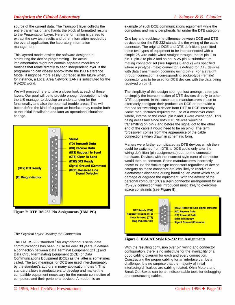
Figure 7: DTE RS-232 Pin Assignments (IBM PC)
source of the current data. The Transport layer collects the example of such DCE communications equipment while theentire transmission and hands the block of formatted results computers and many peripherals fall under the DTE category.to the Presentation Layer. Here the formatting is parsed toextract the raw test results and other information needed by One key and troublesome difference between DCE and DTEthe overall application, the laboratory information devices under the RS-232 standard is the wiring of the cablemanagement. connector. The original DCE and DTE definitions permitted
This layered model assists the software designer in simple 25-wire cable wired straight through, that is pin-1 tostructuring the device programming. The actual pin-1, pin-2 to pin-2 and so on. A 25-pin D-subminiatureimplementation might not contain separate modules orroutines that relate directly to each independent layer. If theprogramming can closely approximate the ISO ReferenceModel, it might be more easily upgraded in the future when,for instance, a Local Area Network (LAN) is substituted for theRS-232 world.
We will proceed here to take a closer look at each of theselayers. Our goal will be to provide enough description to helpthe LIS manager to develop an understanding for thefunctionality and also the potential trouble areas. This willbetter define the kind of support an interface may require bothat the initial installation and later as operational situationschange.
The Physical Layer: Making the Connection
The EIA RS-232 standard for asynchronous serial data3
communications has been in use for over 30 years. It definesa connection between Data Terminal Equipment (DTE) andData Circuit-terminating Equipment (DCE) or DataCommunications Equipment (DCE) as the latter is sometimescalled. The two meanings for DCE are used interchangeablyby the standard’s authors in many application notes . This4
standard allows manufacturers to develop and market thecompatible equipment necessary for the remote connection ofcomputers and their peripheral devices. A modem is an
these two types of equipment to be interconnected with a
mating connector set (see Figures 6 and 7) was specifiedwhere a pin-type (male) connector is defined for DTE deviceswith data transmission occurring using pin-2. For a straightthrough connection, a corresponding socket-type (female)connector was to be used for DCE devices with the data beingreceived on pin-2.
The simplicity of this design soon got lost amongst attemptsto simplify the interconnection of DTE devices directly to otherDTE equipment. In this case some manufacturers chose toalternately configure their products as DCE or to provide amethod for switching a device from DTE to DCE internally.Some manufactures required the use of a crossover cablewhere, internal to the cable, pin 2 and 3 were exchanged. Thisbeing necessary since both DTE devices would betransmitting on pin-2 and before the signal got to the otherend of the cable it would need to be on pin-3. The term“crossover” comes from the appearance of the cableconnections when drawn in schematic form.
Matters were further complicated as DTE devices which thencould be switched from DTE to DCE could only alter thewiring definition (pin assignments) but not the connectorhardware. Devices with the incorrect style (sex) of connectorwould then be common. Some manufacturers incorrectlychose to use the socket-type connectors regardless of devicecategory as these connector are less likely to receive anelectrostatic discharge during handling, an event which coulddamage or degrade the equipment. With the advent of thepersonal computer (PC) a 9-pin connector arrangement for anRS-232 connection was introduced most likely to overcomespace constraints (see Figure 8).
Figure 8: IBM/AT Style RS-232 Pin Assignments
With the resulting confusion over pin wiring and connectorconfiguration, there is no substitute for the availability of agood cabling diagram for each and every connection.Constructing the proper cabling for an interface can be achallenge. It is no surprise that the majority of initialinterfacing difficulties are cabling related. Ohm Meters andBreak-Out Boxes can be an indispensable tools for debuggingand constructing cables.
Interfacing the Clinical Laboratory J. Selmyer & B. Cloutier
© 1996, Med TechNet Presentations October 1996 Page 11
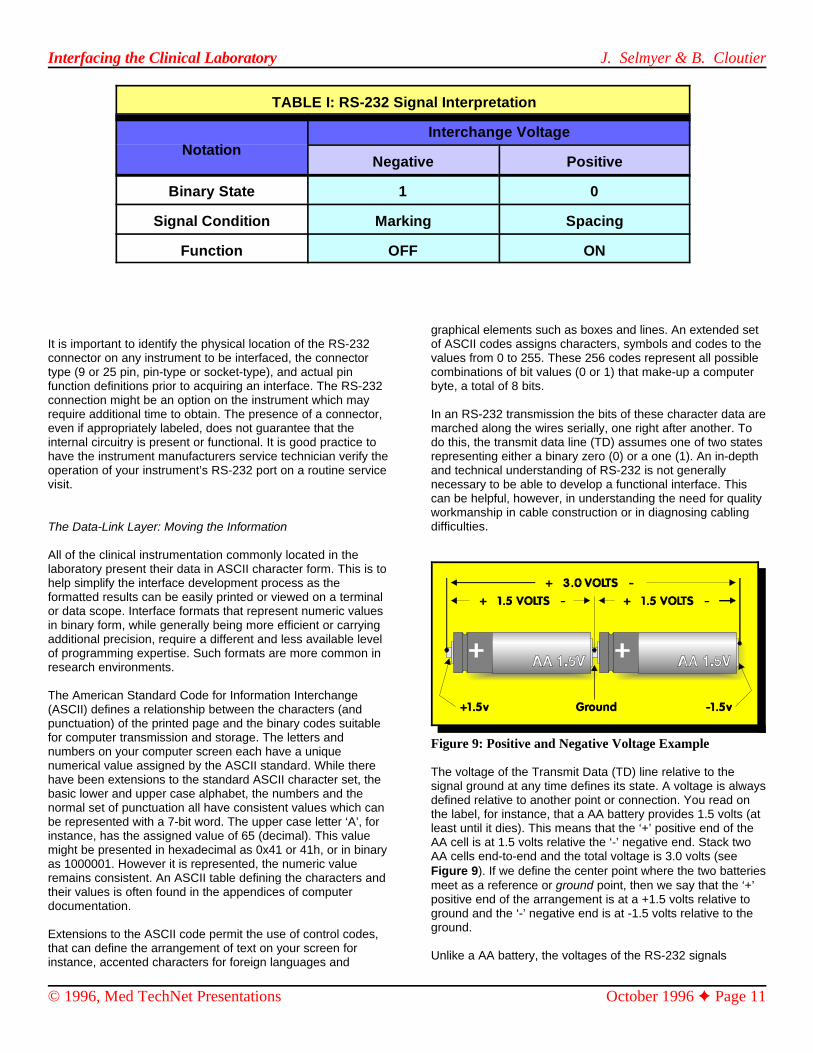
TABLE I: RS-232 Signal Interpretation
NotationInterchange Voltage
Negative Positive
Binary State 1 0
Signal Condition Marking Spacing
Function OFF ON
It is important to identify the physical location of the RS-232 of ASCII codes assigns characters, symbols and codes to theconnector on any instrument to be interfaced, the connector values from 0 to 255. These 256 codes represent all possibletype (9 or 25 pin, pin-type or socket-type), and actual pin combinations of bit values (0 or 1) that make-up a computerfunction definitions prior to acquiring an interface. The RS-232 byte, a total of 8 bits. connection might be an option on the instrument which mayrequire additional time to obtain. The presence of a connector, In an RS-232 transmission the bits of these character data areeven if appropriately labeled, does not guarantee that the marched along the wires serially, one right after another. Tointernal circuitry is present or functional. It is good practice to do this, the transmit data line (TD) assumes one of two stateshave the instrument manufacturers service technician verify the representing either a binary zero (0) or a one (1). An in-depthoperation of your instrument’s RS-232 port on a routine service and technical understanding of RS-232 is not generallyvisit. necessary to be able to develop a functional interface. This
The Data-Link Layer: Moving the Information
All of the clinical instrumentation commonly located in thelaboratory present their data in ASCII character form. This is tohelp simplify the interface development process as theformatted results can be easily printed or viewed on a terminalor data scope. Interface formats that represent numeric valuesin binary form, while generally being more efficient or carryingadditional precision, require a different and less available levelof programming expertise. Such formats are more common inresearch environments.
The American Standard Code for Information Interchange(ASCII) defines a relationship between the characters (andpunctuation) of the printed page and the binary codes suitablefor computer transmission and storage. The letters andnumbers on your computer screen each have a uniquenumerical value assigned by the ASCII standard. While therehave been extensions to the standard ASCII character set, thebasic lower and upper case alphabet, the numbers and thenormal set of punctuation all have consistent values which canbe represented with a 7-bit word. The upper case letter ‘A’, forinstance, has the assigned value of 65 (decimal). This valuemight be presented in hexadecimal as 0x41 or 41h, or in binaryas 1000001. However it is represented, the numeric valueremains consistent. An ASCII table defining the characters andtheir values is often found in the appendices of computerdocumentation.
Extensions to the ASCII code permit the use of control codes,that can define the arrangement of text on your screen forinstance, accented characters for foreign languages and
graphical elements such as boxes and lines. An extended set
can be helpful, however, in understanding the need for qualityworkmanship in cable construction or in diagnosing cablingdifficulties.
Figure 9: Positive and Negative Voltage Example
The voltage of the Transmit Data (TD) line relative to thesignal ground at any time defines its state. A voltage is alwaysdefined relative to another point or connection. You read onthe label, for instance, that a AA battery provides 1.5 volts (atleast until it dies). This means that the ‘+’ positive end of theAA cell is at 1.5 volts relative the ‘-’ negative end. Stack twoAA cells end-to-end and the total voltage is 3.0 volts (seeFigure 9). If we define the center point where the two batteriesmeet as a reference or ground point, then we say that the ‘+’positive end of the arrangement is at a +1.5 volts relative toground and the ‘-’ negative end is at -1.5 volts relative to theground.
Unlike a AA battery, the voltages of the RS-232 signals

Interfacing the Clinical Laboratory J. Selmyer & B. Cloutier
© 1996, Med TechNet Presentations October 1996 Page 12
Figure 10: Typical Form of Character Transmission
change rapidly from positive to negative and back. The RS-232 can be set by the user and must be configured properly. Thesignal voltages are defined relative to the Signal Ground (pin 7 user is responsible for defining the bit rate (baud), the numberon 25-pin connectors). For RS-232, any voltage exceeding a of data bits (7 or 8), the number of stop bits (typically 1) andpositive 3 volts is considered to represent the binary state 0. the use of parity (odd, even, 0, 1 or none). CommunicationsThis is sometimes referred to as the spacing signal condition. Anegative voltage below -3.0 volts relative to signal groundrepresents a binary 1 or marking condition.
Most manufacturers will use +12 volts and -12 volts for the twostates respectively (see TABLE I). This insures that the 3.0 voltlevels are easily exceeded so that reliable communications canbe achieved even when some voltage is lost through longcabling, bad connections or otherwise poor electricalenvironments. Clean and secure connections in cabling areimportant. Shielded cables are necessary to prevent theinfluences of external electrical interference such as thatcaused by laboratory refrigeration units, sample tube rockers,fluorescent lighting, or other heavy duty electrical devices.
Any external event that can influence the signal voltagesenough to have one of them fall into the -3.0 to +3.0 volt rangefor even the briefest moment, can (and will very likely) cause acommunications failure. This could mean permanent electricaldamage but is much more likely to subtly alter an ASCII coderesulting in the reception of character different from what hasbeen sent. The resulting transmission error could completelyalter the meaning of the transmission. Later, we will mentionsome of the ways in which these errors are detected andpossibly corrected or otherwise handled appropriately.
The RS-232 Transmit Data line (TD) takes on the value of a bitfor a duration specified by the Baud Rate (see Figure 10). Itthen is switched to the next bit for an equal length of time andso on. A character’s bits are sent starting from the leastsignificant to the most. Each character is preceded by a startbit (always a marking 1) and is followed by at least one stop bit(always a spacing 0). In this way the time between characterscan vary greatly and data can be transmitted in anasynchronous fashion with no constraints on the exact timingbetween characters.
Since the possibility exists that external electronic disturbancescan corrupt the bit stream, an additional bit called a parity bitcan accompany each character. The parity bit is calculated based upon the value of all of the other bits in the character.Typically the parity bit is a marking 1 or spacing 0 as would benecessary to force the number of marking 1 bits in the currentcharacter to be odd or even (defined by the setup). If atransmission error occurs, it is likely that the parity bit would beincorrect (an odd number of bits results when there always
should be an even number for instance). This then indicatesthat an error has occurred and that the data character maynot be valid. Parity is just one of the many methods used tohandle transmission errors. By itself it is not sufficient toguarantee the detection of all errors. Other more sophisticatedtechniques are needed and are implemented by the TransportLayer protocols.
Fortunately, the electrical part of the RS-232 exchange ishandled in a standard and consistent manner by the individualhardware components in the design. Generally, someparameters controlling the operation of the RS-232 connection
are only successful when both the transmitter and receiverhave been configured with the same baud, bits, stop andparity settings.
In the laboratory, it is important that the LIS manager knowhow to set these parameters on all of interfaced instrumentsand on the corresponding system or intermediate interfacedevice. A log of the proper settings should be maintained tofacilitate the resetting these parameters should they bealtered.
The Network Layer: Identifying the Source
As discussed previously, most instruments are connectedpoint-to-point. In the absence of a network connection, whendata is received we know precisely where it came from justfrom the physical attachment. Within the instrument, theNetwork Layer is trivial. In the LIS, however, the NetworkLayer can insure that some identification as to the data sourceis provided. Many labs have two or more instruments that canperform the same determinations, which may or may not usethe same test methodology. A glucose value, for example,might be obtained from more than one analyzer. A provisionfor assigning values from differing instruments special testnames or otherwise identifying their source, can be importantshould it later be determined that a particular instrument’sresults are faulty, or for routine tracking of qualitycontrol/assurance (QC/QA) information.
The Transport Layer: Understanding the Flow
The RS-232 connection permits the flow of character data inboth directions. Characters can pass from the instrument tothe host computer and, similarly, from the host computer tothe instrument. The maximum rate at which these datacharacters can be moved from one place to another iscontrolled by the baud rate. The baud rate establishes thefixed rate at which bits can be transmitted.
Ten bits (each either a marking 1 or spacing 0) are required topass a single character using the typical parameter settingsfor 8 data bits, 1 stop bit and no parity. The start bit accountsfor the tenth bit: 1 start bit, 8 data bits, and 1 stop bit. For anexample, consider a baud rate setting of 9600 baud. Thisprovides a maximum transmission rate of 9600 bits persecond or 960 characters per second using the typical 10 bits

Interfacing the Clinical Laboratory J. Selmyer & B. Cloutier
© 1996, Med TechNet Presentations October 1996 Page 13
per transmission. This amounts to only about one half of a and software technique exists for this.screen full of ASCII information (12 lines by 80 characters)assuming the transmission of all positions including blanks or The original hardware handshake scheme for RS-232 wasspaces (ASCII 32). devised for use with early modems which could process
The 960 characters per second represents a maximum rate having data to send would assert the Request to Send (RTS)assuming that data is transmitted without pause. The mere signal to the connected modem. Once the modem was readyasynchronous aspect of the RS-232 connection assumes the to take data from the DTE device it would respond with theexistence of some delay between characters. This could be as Clear to Send (CTS) signal. Upon seeing CTS the datalittle as a single bit time or much longer. These delays are characters are transmitted. Finally the RTS signal is removed,often required by the transmitting device which typically builds the modem cancels the CTS signal and the DTE device canthe transmitted message retrieving information from storage then receive a possible response.devices such as disk drives. This retrieval time often results intransmission pauses. As a result, at 9600 baud, the throughput In situations where two DTE devices are interconnected,rarely reaches the 960 character rate. equipment manufactures have taken some liberty in the
Since typical baud rates range from 1200 to 19,200 baud, 9600 RTS of one device is connected to the CTS of the other andis quite common. Yet at this rate it would take two (2) seconds vice versa. The result is the ability of either to stop the flow ofto transmit an entire screen full of information. This would be data from the other. The RTS lines in this situation are used tounacceptable if it weren’t for some of the available techniques control the flow of incoming data rather than as an indicationfor enhancing communication speeds. In the case of the screen that there is data to be sent. As a result, the techniques fordisplay, blanks are normally not transmitted. Some protocols hardware handshaking may differ from device to deviceincorporate data compression. This is all geared towards rendering their interconnection incompatible. With thereducing the transmission length (overhead) and thus confusion over the implementation of the hardwareincreasing the throughput for any fixed baud rate. handshake, a software technique has become more popular.
An RS-232 connection can then present a bottleneck for the The XON/XOFF software handshake defines two specialtransmission of large amounts of data. It is clear that the control characters. To stop incoming data the receiver sendsthroughput limitation depends on the overall size of the an XOFF (ASCII 19) to the transmitter. Transmission istransmitted messages. This will be discussed in more detail in restarted after the receiver is able to free up its buffer spacea later section. It is important to note that the throughput is not by sending the XON (ASCII 17) character. Someonly limited by the transmitter. The system receiving an RS- implementations will restart transmission with any character232 message must be able to do so at a rate equal to or faster following the XOFF. This mode of handshaking requires thatthan the transmitter or data will be lost. the XON and XOFF characters not appear in the normal
Buffering
The receiving system must process the incoming data,extracting numeric and textual data, ultimately filing this newly The Transport Layer: Getting the Message Acrossobtained information into growing data bases. This rarely canbe accomplished fast enough to keep up with the transmitting The RS-232 standard provides us with the ability to movedevice. The receiver then cannot get back to collect incoming characters and other forms of data from one device todata characters in time to insure no loss. another. At this level there are capabilities to control data flow
To prevent data loss, the receiver typically collects the entire robust enough by themselves to insure complete flexibility formessage before beginning its processing. The incoming data is flow control or completely reliable error detection. then analyzed and filed away during times when the transmitteris quiet. The data is collected into a buffer which usually has a A more enhanced form of handshaking can be implementedfixed size and defined large enough to hold the biggest as part of a complete protocol. In these cases a set of controlmessage expected. If the buffer is too small, a large characters are defined which permit the receiver to request atransmission will overflow the buffer and data will be lost. Data transmission and then acknowledge the successful reception.buffers are critical to the reliable performance of the serial link. The protocol might include forms of error checking permittingBuffers are used for both receiving and transmitting functions. the detection of faulty transmissions. When transmission
Handshaking
A data buffer alone cannot completely guarantee zero dataloss. It may not be practical to allocate a buffer larger than themaximum message length or this maximum length might notbe known. The possibility for buffer overflow therefore alwaysexists. To prevent overflow the receiver is provided with ameans by which it can stop the transmitter. Both a hardware specific format of the block or message.
information in only one direction at a time. A DTE device
application of the hardware handshake. In many cases the
message transmissions. This might become a problem whenbinary data formats or error checking characters are included.This will be discussed in a subsequent section.
and to perform error checking. Neither of these techniques are
errors are encountered another control character can causethe retransmission of the message.
These protocols can range for the very simple to the verycomplex depending on the features provided. Each isdesigned to successfully move a block of character datacontaining the formatted result data or other information fromone point to another. This is done without regard to the

Interfacing the Clinical Laboratory J. Selmyer & B. Cloutier
© 1996, Med TechNet Presentations October 1996 Page 14
So you’ve connected an instrument to your LIS with the proper Now what if one device achieves master status in this way andcable, you’ve set all of the proper communications parameters then decides to keep it for as long as it wants? "That's not fair!"and there is data in the instrument ready to go, but nothing is comes the cry from one side of the table. So into the protocolhappening. You’ve double checked the settings and even goes functions to interrupt transfers so that you could arguetested the hardware lines using a break-out box. Still, there is again over the master status. Hopefully winning for your side thisno communications activity. This is a typical situation and the time. And why not include a means to refuse a bid for masterproblem is likely in the protocol. status right from the beginning. These are factors behind the
According to an old Webster dictionary (circa 1957), protocol isdefined, in this sense, as "the ceremonial forms and courtesies The ASTM protocol falls into this category. Control codes for linethat are established as proper and correct in official intercourse bidding and interruption are defined. This effectively tables thebetween heads of states and their ministers". This description master/slave argument so that it might be fought day-in and day-must have been updated certainly in the past 40 years, but even out along your cables. The outcome (on average) might strike athen it encompassed the basic purpose that still has an balance, but much depends and the accuracy of theappropriate meaning. There must be an established, proper and implementation. Unfortunately, the software coding may not fullycorrect procedure for communication. At the software level there implement all codes and timings as accurately as was originallystill remains an element of ceremony. The old definition implies an intended. In some cases, one protocol implementation might beexchange between entities of differing levels of authority. Call it more successful at the negotiating than another, to the advantagewhat you will, but these terms come to mind: speaker/listener, of its owner. It is also feasible that, with such variations, anmaster/slave, or client/server. Indeed we all might know how implementation might yield a particular match between systemprotocol can easily fall by the wayside when there is any and analyzer that is inoperable. This is likely, even if by accident,disagreement regarding the roles of the participants. as the specifications are not straight forward and not for the
The reference to government in the original definition of protocol isnot far off-base as politics certainly has come into play. Sit a Now, back to the instrument that refused to cooperate. There’s nonumber of clinical analyzer manufacturers and information system transmission. In this case, the analyzer is likely to operating as avendors down at a table. Give then the task of defining a slave. It is waiting for the LIS to ask for its data. A simple requeststandardized protocol. A master/slave protocol of some kind might or poll sent by the LIS in the form of possibly only a single controlbe the simplest and a good place to start, however, it is doomed character might unleash a flood of data. Another scenario, mightfrom the start. There is certainly no chance of gaining any have the instrument serving as a master. Here it is sending aconsensus as to whom would be the "master" and whom would be very brief request periodically to the LIS. You may not have seenrelinquished to "slave". This was the scene some years ago during it if it only involved a few control characters sent every fewthe initial meetings of the E31.14 ASTM laboratory Interface minutes. Now the instrument is awaiting a response from the LISStandards group. indicating that it is ready to receive the result data. This response
In many instruments, sample testing is synchronized tomechanical and fluid processes. There is a specific time allotted Some instruments take the master role and make thefor each test and this can lead to timing constraints on the assumption that the LIS is always paying attention. In this caseinformation system interface. This would not be of concern with the entire result data message is transmitted no matter if the LISthe instrument as master and the information system being is ready or not. Now the instrument sits waiting for some form ofresponsible for always paying attention and meeting the timing. acknowledgment from the host that the message came through.On the other hand, information systems serve large numbers of The combinations or possibilities are great. It is the responsibilityusers, multiple input and output devices, process many varying of the Transport Layer protocol to proper initiate the exchangetasks, and have little or no time to focus on any one job for very and then carry it through to its successful completion.long. Not a problem since as master the system can proceedalong as demands dictate and later gather information from the The typical elements of a protocol include:instruments when time allows. The political solution is to considerall devices as being created equal.
Another type of protocol then has a better chance of acceptance.This one serves the "peer-to-peer" interface. With no single devicebeing designated as the master and no third party moderator,either device can begin a data exchange at will. Now the situationoccurs when both begin to talk and neither listens. The protocolmust necessarily become complex here in that both talkers mustback-off a random period of time and retry the transaction. Thisprocedure continues until one or the other device successfullygains control. It is temporarily the master. A typical master/slavehandshake can then follow but the negotiation process has addedsome difficulty to the implementation. This comes at someadditional cost in transaction setup time and protocol overhead.The exchanges are less efficient.
many aspects of such protocols.
average programmer.
could also be just a few characters.
1. Poll. A message transmitted to request data from theinterconnected device.
2. Acknowledgment. A message transmitted as a responseindicating the successful reception of a previousmessage.
3. Retransmission Request. The previous message could not beunderstood. An error of some kind had been detected.The retransmission request asks the interconnect deviceto repeat the previous transmission. It is important thatthe number of retransmissions be limited so as toprevent an infinite retry situation. This would lock-up theconnection.

Interfacing the Clinical Laboratory J. Selmyer & B. Cloutier
© 1996, Med TechNet Presentations October 1996 Page 15
TABLE III: Variable Field Formatting (reduced message size)
0,004,04a,BSC,951127,151534,90513049,C0,,009(cr)(lf)1,WBC,00000,6.7,SAMPLE RERUN(cr)(lf)1,RBC,00000,5.42,(cr)(lf)1,HGB,00000,14.2,(cr)(lf)1,HCT,00000,49.9,(cr)(lf)1,MCV,00000,87.0,(cr)(lf)1,MCH,00000,28.5,(cr)(lf)1,MCHC,00000,36.9,(cr)(lf)1,RDW,00000,14.2,(cr)(lf)1,PLT,00000,326,(cr)(lf)9,90513049,009(cr)(lf)<end of message>
4. Checksum. A calculation is made inclusive of all of the datacharacters within the message exclusive of thechecksum itself. This is typically a summationmodulo-256 of the 8-bit ASCII codes. The checksumis transmitted following the message. The receivermakes its own calculation and compares the result We know that a typical message contains a block of byteswith the provided sum. If the totals match then the containing numeric byte values whose relationship to themessage is accepted assuming that it is error free. letters and numbers that are familiar to us is specified by theThe use of 8, 16 and even 32 bit checksums can ASCII standard. There is little confusion here as ASCIIgreatly improve the probability of error detection over character tables are readily available. Yet, there are differingthat simple afforded by the parity bit. The checksum is applications for the extended portion of the character set,appended to the message in binary or represented in those values from 128 to 255. In communications outside ofsome ASCII form. A binary checksum can be the the United States, many extended ASCII codes are used tosource of problems should its value be confused with represent the accents applied to various letters in otherother control codes pertinent to the protocol. languages. Sometimes the extended codes are used to
5. Longitudinal Redundancy Check (LRC). A different form ofchecksum calculation involving the bitwise exclusivelogical OR (XOR) of the ASCII codes in the message.An 8-bit LRC results from 8-bit ASCII data. The LRCis also appended to the message in similar fashionand with the same concerns as is the checksum. Each message may contain one or more records of
6. Circular Redundancy Check (CRC). A calculation involving apolynomial equation providing a 16, 32 and even 64bit result that can be used in place of a checksum orLRC with significantly better results. The choice ofpolynomial is made to facilitate easy calculation bythe computer using combinations of exclusive OR,shifts and summation. The CRC is appended to themessage in a similar fashion to the checksum with thesame concerns. lines. Although it is not required, many formats use lines to
7. Line Bid. A request used by a device to gain control of aconnection. The device wants to become the Masterover all other slave devices.
The Presentation Layer: Understanding the Message
The information passed from one device to another must berepresented in a format that is universally understood by bothdevices. Unlike the low-level RS-232 bit arrangements and thesophisticated protocol used to the move the data, theformatting is somethingmuch more visible. Sincemost clinical instrumentsformat their data in ASCII,the content of themessages can be easilyviewed using a text editor. Ifa word processor is used, itis best to display themessages using a font withfixed spacing.
There are many variationsused to format information.While it is quite easy to“see” the data, extractingthe information automatically is another matter. Every aspect preceding and following fields by a field separator. This isof the format must be accurately applied at the source and the usually some form of punctuation such as a comma ordestination must use a precisely identical set of rules to extract semicolon. It may simply be a space(ASCII 32) or tab
the information. It is often difficult to achieve such a matchbetween source and destination. This is of concern as eventhe slightest misinterpretation of the procedure can result ininterface failure.
display graphical characters by providingvertical andhorizontal lines, box corners and intersections, as well as, acouple of different line styles. A disagreement between datasource and destination as to the character set can be a sourceof interface difficulty.
information. The term “record” is usually used to describe ablock of data that achieves a particular purpose or containsinformation about a particular item. In the clinical laboratory arecord might provide the test result data for a particularpatient. We would expect other transmissions then to containrecords with test result data for other patients. Each recordfollows a defined structure.
The ASCII characters within a record are often formatted into
facilitate the display or printing of the information. Manyformats define “lines” that are under 80 characters, the typicalscreen display or printer page width. Other formats permitlines up to 255 characters in length, a maximum that can beeasily be handled by some programming languages likeBASIC for instance. A typical line terminates with the carriagereturn character (ASCII 13). Often this character is followedby the line feed (ASCII 10) as might be necessary to move“down” to the next screen position or to advance the printerpaper. In some cases only the line feed terminates a line.Confusion over line termination can provided yet another
cause for interface failure.Lines, as well, need to havesome structure.
Each line of data is brokeninto a number of fields. Afield is simply a group ofcharacters that usuallydefine the value of aparticular item. In theclinical laboratory this mightbe a single test result or thepatient identificationnumber. Each field isseparated from the

Interfacing the Clinical Laboratory J. Selmyer & B. Cloutier
© 1996, Med TechNet Presentations October 1996 Page 16
TABLE II: Fixed Field Formatting (includes blanks)
0,004,04a ,BSC ,951127,151534,90513049 ,C0, ,009(cr)(lf)1,WBC ,00000, 6.7,SAMPLE RERUN (cr)(lf)1,RBC ,00000, 5.42, (cr)(lf)1,HGB ,00000, 14.2, (cr)(lf)1,HCT ,00000, 49.9, (cr)(lf)1,MCV ,00000, 87.0, (cr)(lf)1,MCH ,00000, 28.5, (cr)(lf)1,MCHC,00000, 36.9, (cr)(lf)1,RDW ,00000, 14.2, (cr)(lf)1,PLT ,00000, 326, (cr)(lf)9,90513049 ,009(cr)(lf)<end of message>
character (ASCII 9). the format. Such changes if not designed carefully can render
If all of the fields in a particular data format are of a predefined revision.character length then a field separator may not be present. Inthis case the receiving process extracts the individual fields In the clinical laboratory each instrument performs differingfrom specific positions in the line. The test value, for instance, test methodologies. A standard format wherein a field ismight begin at the 21st character position in the line and assigned for each and every possible lab test is not feasible.contain exactly 12 characters. This is known as a fixed fieldformat (see TABLE II). It can be easily separated into itscomponent parts or parsed but proves to be inefficient fortransmission. Each field must be defined large enough tocontain the longest non-blank character representation or stringthat can occur there. On average, many of the non-blank fieldvalues are shorter than the field length and therefore must bepadded with additional spaces. Fixed field formats usuallycontain an high percentage of blanks which by themselvesconvey no information but must be transmitted.
If field separators are used, the field values can be of anylength. This iscalled a variablefield format (seeTABLE III). Noblanks are requiredto pad fields to anyparticular lengthand the format ismuch moreefficient fortransmission (andstorage). Thereceiving processmust work a littlemore to extract thefield contents aseach line must be scanned for separators in order to obtain thefield values. Here the test value, for instance, might be definedas the third field in the line. Absolute character position beingmeaningless but the order of the fields must be clearly defined.Care must be taken not to include the field separationcharacter within the value of any field. This would confuse thereceiving process and result in interface failure. For example, ifa comma (ASCII 44) separates fields, the comma must bestrictly avoided in field values and there is a tendency to usethe comma in the last name - first name representation of thepatient name. To overcome this, some variable field formatsenclose field values with quotation marks (ASCII 34)allowing the separator then to appear within the value but notother quotation marks.
Variations in field formatting can cause interface problems.Many fields are optional but must still be included ascompletely blank (all spaces) in fixed field formats or an emptyfield (no characters) with back-to-back field separators in thevariable field formatting. As formats are expanded toaccommodate new communications requirements, fields mustbe appended to lines keeping the previous field structure in theline constant and backwards compatible with existinginterfaces. Sometimes optional subfields can exist within anindividual field with these subfields having their own specialfield separator. Also, completely new lines are often added torecords in order to provide new or additional information within
previously functional interfaces helpless and in need of
First of all, the mix of tests is constantly changing. Secondly,we would not want to have to modify the transmitted formatfrom each instrument when new tests are added. Generallythe lab does not have the ability to do this. A standard formatwould be impossible and the LIS would have to use a different(custom) set of rules to interpret data from each instrument.Fortunately, there is a solution.
When an instrument sends a test result, it often identifies thetest method with a test name such as “GLU” or “BUN” in afield preceding the actual value of the test in the format. Thistechnique is sometimes referred to as name-value pair
formatting. It can beaccomplished in anumber of ways.Sometimes andequals sign ‘=‘ (ASCII61) can separate thename and the value asCHECK=“32.4”defining a CHECKvalue of 32.4.Quotation marks arenot always used andname-value pairsmight be restricted toone per line but notnecessarily. This typeof format can be found
in many places. The CONFIG.SYS file on your PC, some.CFG files and the Windows .INI files all use variations of thename-value pair format.
The Application Layer: Getting the Job Done
Ultimately, data is successfully moved from the laboratoryinstruments through the interface to the LIS. The overallapplication often requires that some information flow in bothdirections. Only with properly operational interfaces can youthen begin to actually do the work at hand: manage theinformation. There are a wide variety of LIS capabilitiesproviding many benefits. A discussion of such things hasbeen the topic of many articles and papers in the past and, nodoubt, will continue to stimulate authors on into the future.
Interface Communication StandardsBackground - the need for standards
Most of the problems associated with interfacing clinicalanalyzers to information systems are related to widely varyingdata format and communication protocol specifications acrossthe population of analyzers. While there have been numerousdiscussions of establishing communication standards forinstruments in the past, the analyzer communication

Interfacing the Clinical Laboratory J. Selmyer & B. Cloutier
© 1996, Med TechNet Presentations October 1996 Page 17
environment remains chaotic. This results in considerable In reality, only several analyzer manufacturers have thus fareffort still being dedicated to establishing functional instrument attempted to adopt the ASTM standards. Several of theseinterface connections. manufacturers have only partially implemented the standards.
There is also wide variation in the quality and accuracy of as its interface specification does not conform to the standard,instrument manufacturers' interface specification documents, leaving the user and LIS vendor to sort out the differences onbased on which most instrument interfaces are written. This site.creates the need to modify interface software on site in manycases. There are several problems with the ASTM standards:
This section will address the various elements of • They are far more complicated than iscommunication standards and describe some of the efforts to necessary for clinical analyzer -achieve standardization in this area. information system communications.
Standards structure
There are a number of elements to be considered in thespecification of standards for communication with peripheraldevices such as clinical analyzers. These elements include:
• electrical specifications (RS-232 hasbeen the standard for serialcommunications since the 1970's)
• connectors and cabling (a variety ofconnector sizes and cable definitions arestill in use)
• communication parameters (baud rate,parity, data bits, stop bits, ASCIIstandard character set)
• communication protocol (the"handshaking" required between hostand a peripheral device for dataexchange to occur: ACK/NAK, Polling,Kermit and XModem are examples)
• message blocking (how does each sideof the communication define where amessage begins and ends?)
• message structure (what will be theorder of data fields, or where is thespecimen ID relative to the rest of thedata record?)
• message content (what is the specimenID and what are the test names andresults associated with this ID?)
The ASTM standard
Within the past two years, standards for communicationbetween laboratory analyzers and information systems havebeen defined by ASTM (American Society for Testing andMaterials, Philadelphia, PA) Subcommittee E31.14. There aretwo standards that currently apply: E 1381-91 which definesprotocol and E 1394-91 which defines format/content.
The conceptual goal of the ASTM standard is to simplify theconnection of clinical analyzers to information systems,reducing the development time and expenses involved. Ideally,clinical analyzers would become plug-and-play, in whichinstrument connections could be established quickly andeasily. Analyzer upgrades and replacements would haveminimal effect on host system software.
At least one manufacturer who claims the ASTM documents
This makes the development ofinterface software more complex(expensive) at the host end.
• The current specifications areextremely broad, allowing too muchroom for variances when implementingthe standard. More completeimplementation documents are requiredto provide analyzer manufacturersbetter guidelines in implementing thestandard. This has resulted in anumber of analyzers claimingcompatibility with the ASTMspecification actually requiring aspecific interface program to handle.
• The communication protocol is notcompatible with the way someanalyzers operate. This has preventedsome of the current analyzers fromimplementing the standard.
• The ASTM standard will have little orno effect on instruments already inplace in clinical laboratories.
Much of the concern with complexity of the ASTM standardstems from the high number of data fields that can beexchanged with a clinical analyzer. Many of these fields areunnecessary for the average clinical analyzer, yet they mustbe accounted for in any implementation. Like manystandards, the (ASTM) result is representative of theindividuals defining the standard. In this case, it is heavilyinfluenced by microbiology instrument manufacturers. Microbiology instruments have interface requirements oftendistinct from routine clinical instrumentation, and generallymore complicated. The ASTM standards have extended thislevel of complexity to all analyzers. It is still possible toestablish interface connections to all appropriate clinicalanalyzers, but it will take more effort to do so.
The current published ASTM standards documents are quitelimited in scope. While they define the standard, no specificexamples are included. This leaves too much room forinterpretation by developers at the analyzer manufacturer foran effective standard to result. ASTM recognizes thisshortcoming, and is making some efforts to improve theimplementation guidelines available.
The ASTM standards were developed in 1991. They will notaffect any of the analyzers designed prior to that time,including instruments in current manufacture. The standards

Interfacing the Clinical Laboratory J. Selmyer & B. Cloutier
© 1996, Med TechNet Presentations October 1996 Page 18
are primarily being adopted by some new instruments coming new device to a wall socket, and have the information systemto market, but not all. This leaves many clinical instruments in immediately aware that the new device is on line, and where.use which will not directly support ASTM.
Common Data Format
In 1984, CRT workstation interfaces were introduced thatconverted analyzer data into a Common Data Format andCommunication Protocol (Dawning Technologies). TheCommon Data Format is flexible at the interface level and isable to be modified by the user or vendor into a best fit for aspecific information system. A line of interface productsincluding workstations, PC-compatible card interfaces, networkcontrol software and special entry consoles (DawningTechnologies) are also being manufactured.
While these efforts predate ASTM interface standards, the goalof the Common Data Format is identical to that of the ASTMstandards: to simplify the connection of clinical analyzers toinformation systems and to reduce the associated costs bypresenting a uniform data format to the host system from allanalyzers. A number of these products provide both ASTMand Common Data Format output selections.
The HL-7 Standard
Several years ago, a group of manufacturers and informationsystem vendors formed Health Level 7, or HL-7. This groupattempted to define a standard for communication betweenvarious parts of healthcare information systems (HIS),principally system-to-system communication. In the course oftheir initial efforts, HL-7 became aware of parallel efforts atASTM. While the HL-7 group is organized separately, thecommunication standard they have adopted is largely the workof another ASTM subcommittee within the E31 committeegroup.
The goal of the HL-7 group is to define (and refine) a standardwhich would allow information systems of varying manufacturewithin the hospital to easily connect to each other. Theconnection of different systems to an HIS has involved solvingmany problems similar to interfacing analyzers (widely varyingformats, resulting in much custom software development). TheHL-7 standard was originally defined for communicationsbetween laboratory (and other) systems and an HIS. Recentlythe HL-7 standard has gained acceptance for use betweeninstruments and the LIS by the Veterans Administration (VA)and Department of Defense (DoD) facilities.
The IEEE MIB effort
Several years ago, an effort to standardize communicationacross devices found in the intensive care unit (ICU) settingwas organized by the IEEE (The Institute of Electrical andElectronics Engineers, Inc., New York, NY). This group isworking to define an intelligent network around a system calledthe Medical Information Bus (MIB) standard. The MIB is aimedat defining a new means of connecting the various patientmonitors, ventilators, analyzers, etc. commonly found at theICU beside. The goal is to allow clinicians to simply connect a
The MIB effort is longer range and more encompassing thanASTM standards efforts. The MIB will include a new designfor each level of communication, beginning with a newproprietary connector for these devices. Thus far, the MIBproject has resulted in demonstration of some early stagedevices exclusively for the ICU. The MIB project will likely beactive for several more years before finalized. The mainparticipants are currently equipment and information systemsuppliers to the ICU system market. While the MIB project isnot specifically aimed at the clinical laboratory, it is mentionedhere because the results of their efforts may well have someapplications in the laboratory in the future.
Planning for Instrument InterfacesClinical laboratories planning to modify or augmentinstrument interface connections to their laboratoryinformation systems (LIS) should consider a number offactors before committing to any particular means of handlinginterfaces. As earlier sections of this article have indicated,there are a number of different types of instrument interfaces,and they are not all equivalent in features, function andperformance. Careful examination of individual needs andexpectations early in the process can help prevent surpriseslater on. This planning process is likely to be most beneficialwhen making decisions regarding a complete new LIS, butcan also benefit those making small changes to an existingsystem. Some elements to be considered include thefollowing:
Interfacing instruments currently in the laboratory.
The combination of available, useful and popular clinicalinstruments is in a constant state of change. This creates theneed for frequent development of interface software, eitherdirectly on the LIS or within an intermediate interface device. The approach to interfaces offered by a vendor shouldaccommodate with no delay all the instruments currently inyour laboratory, provided each instrument has a stableinterface available. Some very new instruments may not yethave final software in place, which may prevent interfacedevelopment until complete.
Data buffering.
Most busy clinical laboratories require that analyzers beavailable at all times, without regard to whether the LIS is upor down. Data buffering provides the ability to operate aninstrument without interruption during periods of host systemdowntime or unavailability during backup procedures. Thedata buffer is temporary memory storage between theanalyzer and LIS. It is an important aspect of the instrumentinterface connection. Without data buffering capability,interface connections will be broken during host systemdowntime. If the analyzer is operated during that period, theinformation generated will likely have to be entered into theLIS manually when it comes back on line. The manual catch-up procedure can be very burdensome and may occur whileadditional specimens continue to arrive at the workstation.

Interfacing the Clinical Laboratory J. Selmyer & B. Cloutier
© 1996, Med TechNet Presentations October 1996 Page 19
Users should ask vendors specifically about how instrument such requirements during the planning phase than whenbuffering is provided, and check with other client sites for their interface software development is underway or complete andexperiences. The busier the laboratory, the more important is installed.the attention given to data buffering and procedures to continueoperation through routine system downtime.
Bi-directional Interfaces.
The overwhelming trend in clinical instrument communicationis toward support of bi-directional interfaces, particularly oninstruments capable of random access testing. A bi-directionalinterface can provide a significant savings in technologist timeand improvement in accuracy over the life of the instrument. Users should have access to bi-directional applications asneeded, including upgrades to existing unidirectional interfaces. Bi-directional applications for new instruments that may beacquired in the future should be available within a reasonableperiod of time. Broadcast and query mode interfaces shouldbe available as needed. Users should require the vendor tospecify which bi-directional applications are offered and howthey work. Reference sites should be asked specifically aboutbi-directional interface applications for feedback. Bi-directionalapplications affect the highest volume, most criticalinstruments in the laboratory.
Operation of interfaces. cases, the vendor will have to provide modified host interface
Since there are a variety of interface types and architecture, circumstances should the laboratory allow an instrumentthere are also a variety of routine operational requirements service person to leave the lab before function of the interfaceplaced on the lab’s clinical staff. When considering a new LIS has been verified. If the new software installed in theor a single updated interface, the laboratory staff should make instrument renders the interface inoperable, it may bethe LIS vendor clarify exactly how each interface will operate, necessary to reinstall the old software until the interface canwhat is expected of the technologist in routine operation of the be configured to accept the change.instrument, and what procedures are required for hostdownloading in bi-directional applications. Particular attentionshould be given to multiple instrument situations, regardingflexibility in workload distribution across the instruments,downloading and cleanup procedures.
Integration with other LIS functions.
Users should know what processing of instrument data isoccurring at what point in the system. Key system operatorpersonnel in the lab should have a clear understanding of howthe instrument interfaces relate to other important systemoperations such as result verification, range and deltachecking, and QC functions. This is also important inestablishing validation testing Standard Operating Procedures(SOPs).
Unusual or custom interfaces. Charges to users for new or modified interface applications
The requirements of each interface should be examined for any the costs associated with interfacing are significant and mustunusual aspects. These might include a requirement for be planned for during the acquisition of new instrumentation. additional calculations included in the instrument output, Often, an LIS vendor will provide a discount for multiples ofrescaling of data to better match a similar instrument, the same interface. This creates financial advantages formodification of test names and special handling of additional using several copies of one analyzer where appropriate, or forspecimen identifiers or instrument flags. Many of these using a front end interface system that can convert allrequests, while seeming perfectly reasonable to an individual instrument output into a standardized format.laboratory, may not be applicable to every lab and thereforemay be considered custom modifications to a standard Sometimes overlooked are the costs associated withinterface at additional cost to the client. It is better to identify providing sufficient host I/O ports and cabling. Instrument
Future instrument selections and upgrades.
The method of interfacing chosen by the laboratory shouldaccommodate new instruments in the future with a minimumof disruption to laboratory operations and/or equilibrium of thesystem. It is only a question of time before the laboratory willrequire a new interface application, either as an addition toexisting instruments or as a replacement for an existing unit. The interface method used by the LIS vendor should besufficiently flexible to provide new applications in a reasonableperiod of time. Availability and costs associated with newinterface applications are important questions for referencesites contacted. It is all too common in the LIS industry forusers to wait close to a year for new applications.
A related concern is how to best handle software upgrades toexisting instruments as they are made available by theanalyzer manufacturer. The laboratory should be notified bythe manufacturer in advance of any instrument upgrades thatwill affect the performance of an interface connection. Theuser should then notify the LIS vendor of the planned upgradefor advice on system implications of the change. In some
software to accommodate the instrument upgrade. Under no
Costs.
The costs associated with all elements of interfaceconnections include host resident software, hardware, cablingand any costs associated with peripheral items. The costs fornew interface applications should be clearly defined. Usersshould also understand what costs will be if modifications arerequired later, either to accommodate instrument softwarechange or to add any desired custom features. The projectedcosts should be balanced against the functionality (value)provided by the resulting interfaces. Surprisingly, the pricescharged by some vendors for straight-in software onlyinterfaces are higher than those from other vendors forinterfaces using intermediate devices that may provide addedfunctionality.
vary widely between vendor and instrument. In many cases,

Interfacing the Clinical Laboratory J. Selmyer & B. Cloutier
© 1996, Med TechNet Presentations October 1996 Page 20
connections are most often made via serial RS232 ports, cables. Interface connection cables should be placed as fartypically provided on multiport cards at the host end. At some as possible from potential sources of noise. Communicationpoint, providing one extra port will require an additional MUX cables should be built carefully, using shielded cable with(multiplexor) card or similar device at the host, which may be a proper grounding. Many instrument and computersignificant expense. Similarly, the cost of connection cabling manufacturers recommend connecting Pin 1 to the cablewhen combined with the cost of installing the cable through shield at one end only to reduce noise contaminationwalls, ceilings, etc. can be more than originally planned. These potential. Large instruments should be connected tocosts may be reduced by networking analyzers to a smaller dedicated power circuits. Communication devices should notnumber of host ports (also using less cabling). Users should be powered from circuits shared by other devices with largecontact reference accounts and visit vendor user group motors or other noise producing components. Surgemeetings to acquire additional information on vendor costs and suppressers should be used where feasible. Dataprocedures. communication cables will not be equipped with noise
Reliability.
LIS users quickly become dependent on functional instrumentinterface connections. Nothing less than 100% uptime istolerated. Naturally, this is an impossible standard for anysystem to uphold while keeping system costs reasonable. Users cannot assume that the system will never fail. Thereare, however, many ways in which users can build in someredundancy of critical systems at a reasonable cost. Weaklinks should be explored and reference sites queried forexperiences.
Physical layout of the laboratory.
Bench space in most clinical laboratories is minimal, andinstallation of an information system often adds many newitems to the laboratory, such as terminals, printers, PC’s, andcabling. These items must be anticipated and planned for. Instrument interface connections will introduce their share ofnew devices to the lab hardware confusion. There will be morecables to secure and some devices used to make the LISconnection. Here, again, there may be benefit to networkinginstruments found in one laboratory area to reduce cableconfusion and the number of displays and other relateddevices. Perhaps several clustered instruments can share asingle LIS terminal as well, further reducing hardwarerequirements.
Electronic data communication with analyzers is vulnerable tophysical disruption (tripping on the cable) and to electronicnoise. Noise can be produced by short duration fluctuations inpower line voltage (sags and surges) coming from outsidepower sources, or generated by devices within the laboratory. Refrigerators, fluorescent lights and other devices with motorsor high voltages involved are potential problems. Otheranalyzers in the laboratory can be sources of noise. Acommunication noise problem in one hematology laboratorywas traced to the small tube rocker used to mix specimens. Itwas located next to the analyzer, powered from the samecircuit, and close to the interface connection cable. The smallmotor in the rocker was particularly noisy (electrically),affecting the instrument interface. Powering the rocker fromanother circuit solved the problem which had taken severalweeks to identify.
In the LIS environment, with many electromechanical devicesinterconnected, it is nearly impossible to accurately diagnosenoise problems. Contaminating noise can be introduced viapower lines, communication cables, printer cables, and monitor
suppressers, and remain vulnerable.
Vendor support.
Questions posed by the user should include: How does thevendor typically support instrument interfaces? What are theprocedures for handling problems and the conditions underwhich additional charges to the client can be generated? Areon-site services available should they be necessary, or iseverything handled via modem? The vendor should describehow interface support is handled, then the user should checkreferences closely.
LIS Upgrading.
What options does the user have with interfaces when the LISis upgraded? Are any major LIS upgrades currentlyscheduled? Will interfaces need to be redone or can theexisting interfaces be carried to a new LIS application? Costscan be considerable when all the wheels must be reinvented.
Interface Validation Procedures.
Validation testing requirements for LIS are increasing as theFDA, AABB and other regulatory and industry organizationsincrease scrutiny of these systems. Instrument interfaceshave generally been considered components of the overallinformation system, and validation tested in that context. Theinterface connection by nature has flexible elements,regardless of the specific interface type implemented. AStandard Operating Procedure should be developed by thelaboratory for validating the performance of each instrumentinterface before releasing the interface to routine operation. This must include operation of the analyzer in all possiblemodes and conditions, and following the data stream to itsvarious end points. A careful audit of analyzer and interfaceprocessed data should indicate no alterations from thoseproduced at the analyzer, other than any data modificationsbuilt into the interface system with the approval or direction ofthe laboratories. This interface validation procedure shouldbe performed any time a modification to the instrument orinterface has taken place. Interface implementations thatpermit direct observation of the data stream at various pointsin the communication process may simplify validation testing. Documentation of the interface validation procedures, resultsand personnel involved should be retained.
Interface System Validation

Interfacing the Clinical Laboratory J. Selmyer & B. Cloutier
© 1996, Med TechNet Presentations October 1996 Page 21
Regulatory background
There is no question that the scrutiny of clinical informationsystems by government regulatory agencies, the FDA inparticular, has increased significantly in recent years. The Incorporating instrument interfaces into the validation plancurrent FDA environment of increased regulation andenforcement indicates that this trend will continue for some Instrument interfaces are an integral part of the LIS, handlingtime. To date, most of the attention has been focused on blood all of the data produced by analytical instruments in the lab. bank computer systems. This is the result of public and Since the architecture of instrument interfaces can vary frompolitical concern over the safety of the nation's blood supply straight in software modules to intelligent intermediatefollowing the growing HIV epidemic. However, additional FDA subsystems, the validation plan should reflect the type ofdraft guideline publications have clearly indicated an intent to interface in use. The validation plan should define the variouseventually regulate all clinical information systems in similar types of information which can be exchanged betweenfashion. Since clinical laboratories are increasingly dependent instrument and system in all operating conditions. Thison information systems, formulating a plan to conform to such includes handling of results, units, test names, flags, errors,widening regulation is becoming more important. control material records, calibration information, specimen
The basis for FDA regulation of clinical information systems isthe premise that the computer system is a medical device. In Clinical instruments vary in the variety and type of informationthe regulation of blood bank establishments, the FDA has held they process. There may be a number of user definablethat blood centers are manufacturing pharmaceutical grade aspects to operation of the instrument which affect how itproducts and that the associated information system is a communicates with the LIS. This can include channelprocess control device which directly affects the quality and assignments, result units, format of results, test names,safety of the resulting product. A blood bank information certain flag conditions, communication configurations andsystem may not only control production of the units available other parameters. The validation plan should reflect thesefor transfusion, but also to which patients units are released. differences and expectations for each instrument interface toThis allows FDA to regulate blood banks in the same way as be tested.pharmaceutical manufacturers, requiring them to conform tothe agency's defined Good Manufacturing Practices. The result Finally, it has been mentioned earlier in this document that theis a dramatic increase in documentation requirements to performance of a clinical instrument interface is a state ofassure that all agency requirements are being met. These equilibrium involving the instrument, interface and host LIS. requirements include validation of manufacturing processes, There are applications in which an intelligent intermediateprocedures and systems. interface system performs some planned interpretation to the
The validation plan
The FDA has defined computerized systems to includehardware, software, peripheral devices, personnel anddocumentation. While detailed validation of the variouselements of the system can be a major undertaking, it isbecoming a normal part of the implementation of clinicalinformation systems based on the experiences with blood banksystems. According to the FDA, validation is intended toestablish documented evidence that the information system willconsistently perform according to pre-determined specificationsand quality attributes.
A first step is a close analysis of the system architecture(hardware and software), specifications and risks associatedwith the system. Following this assessment, a detailedvalidation plan can be developed. Any time hardware orsoftware is modified or updated, the system should berevalidated prior to release for general use. A good planshould allow the validation process to proceed as efficiently aspossible with minimal disruption to ongoing laboratoryoperations.
The plan should indicate what types of testing will beconducted, who will develop the test plan, how testing will beperformed, who will run the tests, what forms of documentationwill be available, who will review the testing and who willapprove the testing. When the validation testing is completed,
the plan with testing results and the various approvalsignatures and dates represents a complete documentationpackage for the validation process.
type and any other information handled by the instrument.
instrument data stream. This may include the addition ofsome calculated parameters based on available measuredparameters, reformatting of results to an arrangement morecompatible with other lab reporting, interpretation of flagconditions is a more desirable way, etc. These interpretivesituations must be recognized and incorporated into thevalidation plan for appropriate testing.
Validation testing
FDA describes three aspects of a validation testing plan forblood bank systems: installation, process performance andproduct performance.
Installation Qualification
Installation qualification is intended to ensure that the systemis suitable for its intended purpose, has been installedproperly and is functioning as intended. In the instrumentinterface application, this would include validation of theinstrument's performance on a stand alone basis andvalidation of proper installation and connection of anyintermediate interface system. The host LIS should have theproper interface control software installed and available fortesting.
This phase of validation testing should verify that all of thehardware and software components relative to instrument

Interfacing the Clinical Laboratory J. Selmyer & B. Cloutier
© 1996, Med TechNet Presentations October 1996 Page 22
interface communication are installed and properly configured. Physical (cable) connections should be verified at each step,and the various port configuration parameters checked andrecorded for the proper match at each end of communication. The instrument should be in the proper mode for the desiredtype of interface operation (many instruments have a numberof available settings). Configuration of the interface subsystemshould be documented as having all the necessary matchingparameters set. Similarly, connections and communicationparameters between the interface system and the host LISmust be documented as matching appropriately.
In applications which use an intermediate interface subsystem,it may be possible to further validate interface communicationthrough the use of such tools as transmission logs orcommunication line monitors. This capability may be used tovalidate communication to/from the instrument and to/from thehost LIS. All aspects of interface communication should bedocumented including listings of interface program code. Errorchecking algorithms should be used wherever they areavailable in the instrument communication chain.
Process Performance Qualification
Process performance qualification is defined as establishingconfidence that the process is effective and reproducible. Inthe instrument interface context this can be interpreted to meanvalidation of communication between analyzer and host LIS inall possible modes. Performance testing is usuallyaccomplished in a number of ways including normal, boundary,invalid case, stress and special case tests.
Normal testing includes cases that test the overallfunction and integrity of the system. Input data all fall withinnormal ranges. Sufficient repetition assures that the system isperforming as intended under normal conditions.
Boundary testing uses input values which force thesystem to determine if the input is valid or invalid or to make adecision to execute another element of the software. In thecase of instrument interfaces, this would involve the instrumentprocessing specimens which would generate various range anderror flag conditions which must be interpreted by the interfacesystem and host LIS.
Invalid case testing checks for informational errorswhich should either not be communicated or handled in somespecific manner. Examples include the instrument inhibitingresult output for certain channels under specified conditions;the host attempting to download erroneous information to theinterface; typographical errors at the instrument, etc.
Stress testing is generally testing of the system assembled, the last step is for the appropriate managers tounder volume load conditions. This challenges the system to sign in acceptance of the new/updated/modified system. Theperform as expected at its physical and processing limits. document then serves as a necessary record for anySuch testing would involve operating the instruments at regulatory agencies and also as an important reference whencapacity while including error flag conditions and other record any future modifications are made to the system.types. If an intermediate interface system is employed whichserves multiple instruments, all instruments connected shouldbe operated at capacity simultaneously. Buffer full and powerfailure conditions should be checked. This is typically worstcase scenario testing.
Special case testing documents the system'sreaction to specific types of data or lack of data and isintended to ensure that the system does not accept unsuitabledata. Examples would include what happens with multipleinstruments communicating simultaneously, missing datafields, or with result information outside of acceptable ranges. Instruments should be exercised to produce all possiblerecord types.
Completion of these various types of system testing shouldmake the operators more familiar with the system and shouldhave generated every possible flag and error condition.
Product Performance Qualification
Product performance qualification involves validating theintegrated system as a whole. This involves testing that theinformation produced by the clinical instrument arrives at thedesignated place in the LIS database intact, with allappropriate related information. All relevant storing andreporting aspects of the LIS must be examined anddocumented to ensure that result information being generatedby the instruments are properly reported on any paper reportsor electronic communication to another (HIS) system. Incases where some planned modification of the data takesplace at instrument output, within an intermediate interfacesystem or on the host LIS itself, the modifications should betested for accurate performance under all conditions. Performance testing may be handled via parallel testingagainst another system and on-line monitoring once the newsystem is placed in regular operation. Parallel testing of anew LIS is very common prior to "going live". While paralleltesting does not generally validate the system in all possiblemodes of operation and should not therefore be the only typeof testing done on the system, it can serve as a valuable wayto learn the new system and spot any irregularities withnormal system operation prior to stress and other testing.
Analysis and review
Once the validation testing is complete, the resultinginformation must be compiled, analyzed and reviewed. Thisprocess will include organization of the testing documents andwritten explanations of why any tests produced results otherthan expected. In some circumstances, work-arounds will beidentified to deal with any processing shortcomings.
Acceptance
With the validation testing completed and the documentation
Revalidation
Instrument interface applications in clinical laboratories arefrequently modified, updated or added to the system as new
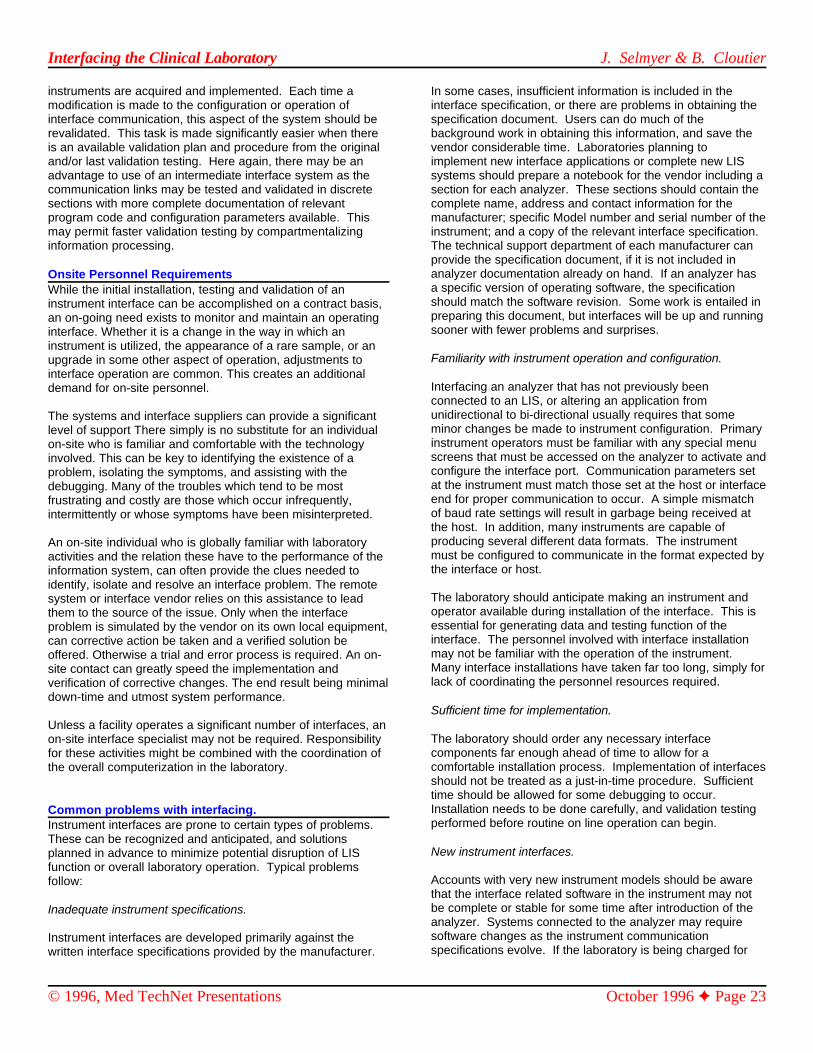
Interfacing the Clinical Laboratory J. Selmyer & B. Cloutier
© 1996, Med TechNet Presentations October 1996 Page 23
instruments are acquired and implemented. Each time a In some cases, insufficient information is included in themodification is made to the configuration or operation of interface specification, or there are problems in obtaining theinterface communication, this aspect of the system should be specification document. Users can do much of therevalidated. This task is made significantly easier when there background work in obtaining this information, and save theis an available validation plan and procedure from the original vendor considerable time. Laboratories planning toand/or last validation testing. Here again, there may be an implement new interface applications or complete new LISadvantage to use of an intermediate interface system as the systems should prepare a notebook for the vendor including acommunication links may be tested and validated in discrete section for each analyzer. These sections should contain thesections with more complete documentation of relevant complete name, address and contact information for theprogram code and configuration parameters available. This manufacturer; specific Model number and serial number of themay permit faster validation testing by compartmentalizing instrument; and a copy of the relevant interface specification. information processing. The technical support department of each manufacturer can
Onsite Personnel RequirementsWhile the initial installation, testing and validation of aninstrument interface can be accomplished on a contract basis,an on-going need exists to monitor and maintain an operatinginterface. Whether it is a change in the way in which aninstrument is utilized, the appearance of a rare sample, or anupgrade in some other aspect of operation, adjustments tointerface operation are common. This creates an additionaldemand for on-site personnel.
The systems and interface suppliers can provide a significantlevel of support There simply is no substitute for an individualon-site who is familiar and comfortable with the technologyinvolved. This can be key to identifying the existence of aproblem, isolating the symptoms, and assisting with thedebugging. Many of the troubles which tend to be mostfrustrating and costly are those which occur infrequently,intermittently or whose symptoms have been misinterpreted.
An on-site individual who is globally familiar with laboratoryactivities and the relation these have to the performance of theinformation system, can often provide the clues needed toidentify, isolate and resolve an interface problem. The remotesystem or interface vendor relies on this assistance to leadthem to the source of the issue. Only when the interfaceproblem is simulated by the vendor on its own local equipment,can corrective action be taken and a verified solution beoffered. Otherwise a trial and error process is required. An on-site contact can greatly speed the implementation andverification of corrective changes. The end result being minimaldown-time and utmost system performance.
Unless a facility operates a significant number of interfaces, anon-site interface specialist may not be required. Responsibilityfor these activities might be combined with the coordination ofthe overall computerization in the laboratory.
Common problems with interfacing.Instrument interfaces are prone to certain types of problems. These can be recognized and anticipated, and solutionsplanned in advance to minimize potential disruption of LISfunction or overall laboratory operation. Typical problemsfollow:
Inadequate instrument specifications.
Instrument interfaces are developed primarily against thewritten interface specifications provided by the manufacturer.
provide the specification document, if it is not included inanalyzer documentation already on hand. If an analyzer hasa specific version of operating software, the specificationshould match the software revision. Some work is entailed inpreparing this document, but interfaces will be up and runningsooner with fewer problems and surprises.
Familiarity with instrument operation and configuration.
Interfacing an analyzer that has not previously beenconnected to an LIS, or altering an application fromunidirectional to bi-directional usually requires that someminor changes be made to instrument configuration. Primaryinstrument operators must be familiar with any special menuscreens that must be accessed on the analyzer to activate andconfigure the interface port. Communication parameters setat the instrument must match those set at the host or interfaceend for proper communication to occur. A simple mismatchof baud rate settings will result in garbage being received atthe host. In addition, many instruments are capable ofproducing several different data formats. The instrumentmust be configured to communicate in the format expected bythe interface or host.
The laboratory should anticipate making an instrument andoperator available during installation of the interface. This isessential for generating data and testing function of theinterface. The personnel involved with interface installationmay not be familiar with the operation of the instrument. Many interface installations have taken far too long, simply forlack of coordinating the personnel resources required.
Sufficient time for implementation.
The laboratory should order any necessary interfacecomponents far enough ahead of time to allow for acomfortable installation process. Implementation of interfacesshould not be treated as a just-in-time procedure. Sufficienttime should be allowed for some debugging to occur. Installation needs to be done carefully, and validation testingperformed before routine on line operation can begin.
New instrument interfaces.
Accounts with very new instrument models should be awarethat the interface related software in the instrument may notbe complete or stable for some time after introduction of theanalyzer. Systems connected to the analyzer may requiresoftware changes as the instrument communicationspecifications evolve. If the laboratory is being charged for

Interfacing the Clinical Laboratory J. Selmyer & B. Cloutier
© 1996, Med TechNet Presentations October 1996 Page 24
modifications to interface software, it may well wait for an readily available and inexpensive. Many facilities alreadyinstrument to stabilize before developing the interface make use of it to link their systems with one another. It is onlyapplication. When planning a new interface application, the a matter of time before clinical instruments are equipped withvendor should be asked its experiences with new instrument a direct network connection.models, and which of the instruments the laboratory plans tointerface may present such problems. The analyzer The volume of information processed will continue to grow.manufacturer should be questioned regarding the status of Many devices now can report their results in graphical form.instrument based software. Graphic images, which were once drawn with ASCII
Future ConsiderationsAs laboratory information systems become more sophisticatedand strive to provide many more benefits, additional demandswill be placed on the instrumentation connections. This trend isapparent. Over the past fifteen years the on-line analyzer hasgrown from a novel experiment to an absolute necessity. Thefunctionality of these connections has increased from thesimple unidirectional collection of results to the sophisticatedbi-directional specification of testing requirements. Reportingrequirements have continually increased the variety ofinformation exchanged. Earlier instruments merely passedsimple numeric values while those interfaces today exchangeincreasing amounts of statistics and demographics.
The resulting increase in the information flow betweeninstrument and LIS has begun to stress the serial RS-232communications technology. The need for more accurate andreliable connections has forced the development of increasinglycomplex protocols to control the flow. Today’s protocolsimplement additional levels of error control. This is becomingof more concern in the face of increasing governmentregulation.
The increase in protocol complexity has brought the lack ofsuccessful standardization to the forefront of concern. Thesheer volume of the information exchanged has reached thelimits of RS-232 capacity and the bottleneck effect is apparent.The use of data compression technologies has broughttemporary relief. Clearly we will soon reach the end of theusefulness of the RS-232 connection. The on-going efforts tostandardize communications in this environment will be fornaught. We will have to leave RS-232 behind long before thebenefits of RS-232 based standards in the laboratory arerealized.
The reliance on the bi-directional connection of instrumentationwill grow. This function, which in its original form simplyspecified the tests to be run on a sample-by-sample basis, nowgrows to incorporate varying levels of instrument control.Those familiar with control system design know that delays inthe availability of information, sometimes even on the order ofmicroseconds, can make the difference between function andfailure. RS-232 serial communications cannot provide the levelof response that will be required. Many other industries havelong realized this and have adopted other technologies.
For the clinical laboratory, the future interfaces will incorporatethe local area network technologies available today. Even thesimplest of local area networks can move data at over 100times the rate possible with RS-232 with the more commonnetworks handling information tens of thousands of timesfaster. The hardware and technology is off-the-shelf. It is
characters, now are commonly done in high-resolution color.Instruments which can create and display such graphicstoday, cannot forward their images to the LIS. The RS-232limitation is a barrier to this. Even in the network world, thesegraphical images are routinely exchanged using datacompression as their size can be limiting at 10 million bits persecond. Yet, graphics are becoming commonplace in theinformation industry and will likely become so in the clinicalarena as well.
Of interest is the effect that this move to high performancelocal area networks (LAN) and graphics will have on thestandardization efforts. In fact, the need for low-levelstandards development is eliminated. Widely adoptedstandards already exist. The interconnection hardware, theelectronic elements, and the protocols are all defined. The firstfive (5) levels of the ISO reference model for interconnectiondiscussed earlier are givens. The Physical, Data-Link,Network, Transport, and Session functions required toestablish connection are already well-defined.
Even with graphics, many formats are widely in use and mostsystems can handle the common forms. The clinical industrywill likely adopt a single format (.GIF for instance). Whatremains is the specification of the proper formatting for theactual test results, test requests, and other related messages.And it would seem that continued use of the ASCII formatsthat we commonly encounter today would be appropriate. Thiswill certainly continue to require the attention of the standardsgroups.
SummaryThis article has attempted to highlight some of the variablesand considerations of which a clinical laboratory should beaware in dealing with instrument interface connections toinformation systems. In the past, LIS clients simply acceptedwhat the vendor offered, with no questions asked. Manyusers are currently moving into third- and fourth-generationlaboratory systems, and are asking more difficult questions ofvendors prior to commitment. The vendors must providemore information and in many cases modify the productslightly to accommodate the client. Two final considerationsfor LIS users are user control and options.
User control.
Laboratory personnel should explore their level of control overinstrument interface applications with a new LIS. Somevendors allow access to interface related code, which mayenable users to implement their own new interfaceapplications. In general, interface applications involving aperipheral device will have greater flexibility than straight-insoftware-only interfaces which need to be replaced completelywith instrument change. Users should compare and contrast

Interfacing the Clinical Laboratory J. Selmyer & B. Cloutier
© 1996, Med TechNet Presentations October 1996 Page 25
the various options for instrument interfaces to balancefunctionality, control and cost. Anticipating additions andmodifications to the mix of instruments in the laboratory overthe life of the system may alter the preferred method ofinterfacing to one that provides more user control. A new LISwill usually outlive a number of lab instruments.
Options for Users
The core staff of laboratory management should carefullyconsider all aspects of a planned LIS implementation, includingmethods of interfacing equipment. It may be that the bestmethod of interfacing for a laboratory is different from thestandard method supplied by a vendor. Most vendors are ableto accommodate some changes to interface methods withoutgreat difficulty. Laboratory management should discussinterfaces in detail with the LIS vendor prior to execution of anew contract. Questions should be asked early in the process. The ability to make changes or consider other options forinterfacing (and other elements of the system) may decreaseexponentially following signing the contract.
References1. Mischelevich DJ, Tuefel BG. Capacity planning guide
for mainframes running the IBM Patient Care System(PCS). Computers in Hospitals 1981, Sept/Oct: 19-25.
2. ISO 7498-1984(E) International Standard for OpenSystems Interconnection - Basic Reference Model,UDC 681.3.01
3. EIA-232-D, Interface Between Date TerminalEquipment and Data Circuit-Terminating EquipmentEmploying Serial Binary Data Interchange, ElectronicIndustries Association, ANSI/EIA-232-D-1986,January 1987.
4 Industrial Electronics Bulletin No. 9, Application Notesfor EIA Standard RS-232-C, Electronic IndustriesAssociation, May 1971.
Med TechNet Presentations ...
The online discussion for this presentationcan be found in Conference Area #61, on MedTechNet; and will be active from October 7through November 4, 1996. Successfulcompletion of the online post-quiz earns theparticipant 4.0 P.A.C.E.® CEU’s or CaliforniaState accredited credits.
This is a presentation of Med TechNet OnlineServices for the Clinical Laboratory. “Talks”,such as this one, last for three weeks, duringwhich time, the author and other participantsdiscuss the topic. Users can participate by
telnet’ing to Med TechNet on the Internet at,bbs.medtechnet.com, or dialing in directly,via modem, at, 1-716-688-1552, or, 1-716-636-8235. Discussions can also be distributedvia Internet E-Mail.
For more information, visit the Med TechNetWeb site, http://www.medtechnet.com, orcall toll-free, 1-800-836-0720 (M-F, 9a-4pEastern).
Med TechNet is a service of Western NewYork Microcomputer, Inc., PO Box 84, EastAmherst, NY 14051, USA


![Clinical and Laboratory Standards Institute: …060712].pdfClinical and Laboratory Standards Institute: Addressing POCT Needs; The Good, The ... in vitro diagnostics; LIS, laboratory](https://static.fdocuments.us/doc/165x107/5ac01a5a7f8b9a5a4e8b96d7/clinical-and-laboratory-standards-institute-060712pdfclinical-and-laboratory.jpg)


![Practical interfacing in the laboratory using a pc for instrumentation data analysis and control 9780521815277 36020 c20041214 [630]](https://static.fdocuments.us/doc/165x107/5404e3d78d7f729e768b4968/practical-interfacing-in-the-laboratory-using-a-pc-for-instrumentation-data-analysis-and-control-9780521815277-36020-c20041214-630.jpg)