
Interface standards for automated coal mining equipment
84
NBSIR 77-1301 Interface Standards for Automated Coal Mining Equipment Bradford M. Smith Richard W. Markley, Ph.D. Louis Costrell George E. Clark, Ph.D. Ira W. Cotton Jogrinda M. Bakshi Office of Developmental Automation and Control Technology Institute for Computer Sciences and Technology National Bureau of Standards Washington, D.C. 20234 Interagency Report July 1977 Prepared for U.S. Bureau of Mines Pittsburgh Mining & Safety Research Center 4800 Forbes Ave. Pittsburgh, Pennsylvania 15213
Transcript of Interface standards for automated coal mining equipment

NBSIR 77-1301
Interface Standards for
Automated Coal MiningEquipment
Bradford M. Smith
Richard W. Markley, Ph.D.
Louis Costrell
George E. Clark, Ph.D.
Ira W. Cotton
Jogrinda M. Bakshi
Office of Developmental Automation and Control Technology
Institute for Computer Sciences and Technology
National Bureau of Standards
Washington, D.C. 20234
Interagency Report
July 1977
Prepared for
U.S. Bureau of MinesPittsburgh Mining & Safety Research Center
4800 Forbes Ave.
Pittsburgh, Pennsylvania 15213

NBSIR 77-1301
INTERFACE STANDARDS FORAUTOMATED COAL MININGEQUIPMENT
Bradford M. Smith
Richard W. Markley, Ph.D.
Louis Costrell
George E. Clark, Ph.D.
Ira W. Cotton
Jogrinda M. Bakshi
Office of Developmental Automation and Control TechnologyInstitute for Computer Science and TechnologyNational Bureau of Standards
Washington, D.C. 20234
July 1977
Interagency Report
Prepared for
U.S. Bureau of MinesPittsburgh Mining & Safety Research Center4800 Forbes Ave.
Pittsburgh, Pennsylvania 15213
U.S. DEPARTMENT OF COMMERCE, Juanita M. Kreps, Secretary
Dr. Sidney Harman, Under Secretary
Jordan J. Baruch, Assistant Secretary for Science and Technology
NATIONAL BUREAU OF STANDARDS, Ernest Ambler, Acting Director

TABLE OF CONTENTS
INTRODUCTION 2
BACKGROUND 3
INTERFACE STANDARDS 5
STRATEGIES FOR MODULAR CONTROL SYSTEMS . . . 8
STANDARDS FOR THE LOCAL INSTRUMENTATION INTERFACE ... 12
Analog InterfacesDigital InterfacesSummary Data Sheets
STANDARDS FOR THE SYSTEM CONTROL INTERFACE 24
Star ConfigurationBus ConfigurationRing ConfigurationData Link Control ProtocolsSummary Data Sheets
CONCLUSIONS 36
APPENDICES
A. Statement of Work •••••••••••• 38
B. Interface StandardsTTL 3920 MA CURRENT LOOP 43RS 232-C 45RS 449 51IEEE 583 54IEEE 488 61MILSTD 1553 A 66ANSI X3»28 70ANSI ADCCP 73
Page 2
INTRODUCTION
This report describes work done at the National Bureau of Standards ( NBS ) oninterface standards applicable to the use of computer control systems withautomated mining equipment. The report identifies, analyzes, and recommendsinterface standards applicable to the modular control system of an AutomatedExtraction System (AES) being built by the US Bureau of Mines (USBM). Thework is intended serve both as a technical guide and as a summary ofexisting and forthcoming standards applicable to computer control systems.Selected defacto standards are also included for completeness. A completedefinition of the scope of work is included in Appendix A.
Since the system configuration of the AES control system has not yet beendefined, this report uses several alternative architectures to illustratevarious interfaces that may be encountered. The benefits and limitations ofthe formal and defacto standards which apply to these interfaces are thendiscussed. In this context, standards are recommended for the supervisorycomputer - local control computer interfaces and the local control computer- sensor and actuator interfaces. The best use of these standards andimportant trade-offs are identified and explained.
A critical consideration in the design of any control system is thespecification of interface requirements. The use of formal standards atthese interfaces simplifies the definition and results in a modular systemwhich is easily maintained and which offers the flexibility of futureincremental modifications without total system redesign. It is important tonote that the report considers standards only at the interfaces betweenmodular elements of computer based control systems., By adequatelystandardizing the module interfaces, NBS believes that the Bureau of Mineswill be assured of achieving their system performance objectives whileleaving vendors free to utilize their creativity and resourcefulness inimplementing the functions within any module. The limited use of standardsin this way will help both the Bureau of Mines and the vendor develop themost effective control system. This philosophy is general purpose in natureand ha3 application to many complex technical systems developed by thegovernment.

Page 3
BACKGROUND
One of the strongest motives for developing automation in the miningindustry is the need to increase productivity. With many coal-fired thermalpower plants planned to fill the capacity shortage created by the delays inplacing nuclear power plants into operation and the economic need to convertgas and oil-fired plants to coal, there is a immediate need to increase coalproduction. However, there has been a decrease in productivity in USunderground mines ever since 1969* Productivity has fallen from an all timepeak of 15-6 short tons mined per man day in 1969 to 8.5 ton3 in 1976. Thisdecrease is attributed to several factors including the Federal Coal MineHealth and Safety Act of 1969 and changes in the nature of the work force.
With this goal in mind, the US Bureau of Mines is developing an automatedcoal extraction system (AES). About 30% of all US bituminous coalproduction is by room-and-pillar continuous mining methods where electricpowered machinery such as the rotary drum continuous miner is capable ofmining 5 to 20 tons per minute. Despite this high peak production rate ofthe continuous mining process, the average rate is only a small fraction asa result of many labor intensive support functions. These additionaloperations include such tasks as roof bolting, bridge conveyor operationsand hauling consumable supplies. The AES is planned to increaseproductivity by H5% through the automation and integration of several ofthese functions.
The AES is a 50-ton prototype continuous miner which combines several ofthese important complex operations so that the raining operation is truly"continuous." For example, it has the capability to both mine and installroof bolts without retreating from the face of the coal seam. At thepresent time, as noted above, the mining and mandatory roof bolting, (whichsecures the mine roof) are done by two separate processes which cannot bothbe accomplished in the same working area simultaneously. The machine iscontrolled by three personnel who sit in protected cabs of the AES.
The operating environment is harsh for introducing computers andinstrumentation. The humidity is 100J and temperatures range from 0 degreesCelsius to 60 degrees Celsius. Sulfuric acid is constantly forming from the
* sulfur released from the coal. Methane is also liberated from the coal and,along with coal du3t, presents an explosion hazard. Vibration is a
problem— in one experiment, an inertial guidance system was unable towithstand the shocks and vibrations. Electrical noise may be a problemsince the machine draws considerable electric power for its drive motors.This means that large currents are being switched to and from inductiveloads, which can result in severe transient signals.
.
The typical operation of this device is to approach the coal face oncrawlers (tractor treads) and become positioned. Two sets of overhead jacks
[
wedge the AES into the mine and the cutting cycle begins. A normal cuttingcycle consists of raising the hydraulic "sunping boom" until the rotary drumcutters touch the roof and then moving the sunping boom forward into thecoal seam or "sumping" to the appropriate cut depth, at a rate of 0.2 to 1
I
'

Page 4
inch per second. The boom is then lowered toward the floor in a processcalled shearing, and the rotary drum cuts the coal from the ceiling to thefloor. Although the gathering arms and conveyor may have been in operationduring cutting, there will probably be some spillage of coal, and there isalso a cusp where the gathering arms come together at the floor behind thecutting drum. Therefore, the sumping boom next draws back to clean thefloor. The boom is then raised, and the cycle is repeated. One cycle maytake about four minutes. At the present time this sequence is controlled bya drum programmer.
Concurrent with this operation, the roof bolting section of the AES iskeeping up with the operations. It installs a row of 4 bolts across theroof on 1.2 meter centers. It is planned that the forward raining section beextended from the roof-bolting section in such a way that the roof is alwayssupported by the AES itself. After a row of roof bolts are inserted, theroof bolting section of the AES can move forward.
The AES operates in conjunction with a conveyor haulage system which canextend 30 meters to collect the coal disposed at the tail boom conveyor ofthe AES and transport it to larger conveyors which take the coal to thesurface. The opposite end of the conveyor system will be an important partof the AES's guidance system. The conveyor system is composed of threesections which can extend and contract and are Joined at their ends to eachother. A "vector" guidance system is planned which will measure theirlength and angle with respect to each other as well as to the fixed end, andthus locate the AES to one part in 100 in the X-Y plane. In this manner theAES knows its location relative to the fi>ed point.
Thus, it is possible to identify four distinct operations of the AES: thecutting cycle, the roof support cycle, the roof bolting cycle, and theguidance function. Presently, the control systems involved in theseoperations are either of the drum programmer type or are manual. USBManticipates the development of a computer based AES control system toautomate and integrate these operations. This report investigates the useof interface standards in such a development.
Page 5
INTERFACE STANDARDS
In the development of a computer based control system for the AES there willbe a wide variety of interfaces to define. An interface in a datacommunications system is a common boundary which enables two units toexchange information and control each other's operation. There are manydifferent aspects to an interface, including hardware, operating procedures,and software. Communications interfaces are specified at several, generallyindependent, levels. Each of these levels specifies 3ome additional aspectof the total operation.
To unravel the mysteries of a communications interface, it's best toconsider a simple (but not too simple) example
,such as the interface
between a synchronous terminal — a remote batch entry station — and amodem
.
First of all is the mechanical aspect of the interface. This specifies theway in which the two devices are actually connected mechanically. ItIncludes the number of wires and the dimensions of the physical connectors(generally a male and female connector are specified) in which the wiresterminate. For example, a 25-pin connector is currently in widespread usefor computer-communications interfaces.
The electrical aspect of the interface specifies the voltage levels andduration (or for some interface specifications, the current flow) to be usedfor signaling on the various leads. The basic capability provided byadherence to the standards at this level is the transfer of data bits acrossthe interface.
The way in which the data bits are interpreted is the subject of theprocedural aspect of the interface. This portion of the interface specifieshow the data bits and/or characters are grouped into fields for the purposesof signaling and data transfer. Specifications at this level determine thelegal sequences of communications control characters, or the legal contentsof various fields, or the valid commands and responses in controlling dataflow. The same basic set of control characters or fields may be used in avariety of different ways according to the procedural specifications.
The final aspect of communications interfaces are the protocols which definethe conventions used at various levels for initiating or terminating calls,for data link control and in general to govern the actual flow of dataacross the interface.
It is probably the protocol that is most difficult to understand. Protocolcan be defined as "a formal set of conventions governing the format andrelative timing of data exchange between two communicating processes." A3you might expect, each phrase in the definition is significant and needsexplaining. A simple example might be the best way to do that.

Page 6
When you call someone on the telephone, there is a protocol that bothparties must follow to establish and maintain the conversation and to conveyinformation. Knowledge of the phone number and how to dial it is part ofthe protocol, as is the called party's recognition of the bell as a signalto pick up the receiver. The party then says "Hello" or something to thateffect. When this happens, you reply with your identity, and the mainbusiness of the conversation begins. If not, you inquire for the rightparty, receive an acknowledgement ,
and the conversation begins.
During the conversation both parties speak the same language, one at a time,pausing at the appropriate time for the other to reply. If there is toolong a pause before a reply, the one who last spoke may inquire if the otheris still there. r’inally, you finish your conversation, say goodby, and hangup. All these procedures and conventions are part of the protocol necessaryto use the telephone.
Note that the procedure for the call may be broken into several parts with a
separate set of conventions for each part. First there is a callestablishment phase, which for telephone usage includes dialing, recognizingthe ring, answering, and identifying both calling and called parties. Thereare two time-outs included in the protocol for this phase: 1) if the phoneis not answered after a certain number of rings, you will hang up; and 2)after the receiver is lifted you will wait a certain period of time for ananswer before saying "Hello?" The person answering the phone will likewisewait a short period of time after saying "Hello" for his reply.
After the call establishment phase comes the data transfer phase: theparties talk to each other and transact their business. The mechanics ofthis data transfer are basically two-way alternate, commonly calledhalf-duplex, in which either party but not both can speak. There is a
time-out period whenever the speaker pauses, after which he will inquire ifthe other party is still there. (In computer communications these inquiriesare commonly called handshaking.) If there is no reply to an inquiry, it maybe repeated a number of times, after which the conversation may end.
Finally, the business of the conversation is completed, and each speakerindicates to the other the intention to terminate. Only after each partyagrees and the agreement is acknowledged does the conversation end. Eachparty then closes down the connection (hangs up).
Looking back at the definition of protocol now, "A formal set ofconventions" means that there are a set of rules that both sender andrecipient understand and agree to use. (For computers it is critical thatthe rules be well defined and complete.) Message format applies moredirectly to data communications than to human speech, though even spokenEnglish has its own format. "Helative timing" is quite important, for itdetermines who transmits and who receives at a given time, and alsospecifies time-outs. The term "communicating processes" generalizes thenotion of sender and receiver; in data communications, it empnasizes thatcommunications may occur between different types of equipment.

Page 7
There are then Tour major aspects of an Interface:
MechanicalElectricalProceduralProtocol
Of these, the first three are generally handled by hardware while the lastIs often implemented in software. In data communications, protocols governthe information interchange between two units, one or both of which may be a
program in a computer. Coupled with the mechanical, electrical andprocedural aspects, they completely define the interface. Standards alreadyexist
tin each of these areas. Some are more comprehensive than others in
that they address several or all of the elements of the interface at once.These points should be kept in mind as we define a proper role for interfacestandards in the development of the AES control system.
Page 8
STRATEGIES FOR MODULAR CONTROL
There are five basic components to a control system. These include theactuators, sensors, controller, man-machine interfaces, and the process oractivity itself. The actuators are those elements which can effect a changein the operating variables of the process, and include such devices asmotors, heaters and valves. Sensors measure the changes in the operatingvariables and include such devices as thermocouples, pressure transducers,and proximity switches. The controller processes the signals from' thesensors and issues the required commands to the actuators to maintain aprogrammed course of action. The man-machine interfaces permit people tointeract with the system to make limit adjustments and to monitor thesystem's operation. The last component is the activity itself which isbeing controlled. Before considering architectures for the control system,it is useful to examine three of these elements in more detail: theactuators, the sensors and the controller.
Sensors and Actuators
In general, sensors and actuators are needed by every control system tomeasure Important operating variables and to cause changes in the activity.Both mechanical and electronic types of each component may be used dependingon the control system. The AES electronic control system requires sensorsand actuators which communicate by means of voltages or currents with thecontroller. Considering the computer based controller planned for the AES,the sensor input must at some point be digitally coded for processing. Ifthe sensors are transmitting analog voltages, the computer will require aperipheral analog-to-digital converter for transforming those signals intothe proper form. If there are digital signals or a string of digitalsignals, other types of peripherals will be necessary to process theinformation.
The sensors themselves may produce either digital or analog information. A
sensor with digital information may simply tell the control system of anon-off condition in the process such as exceeding a position limit. On theother hand, analog inputs from sensors are often required to report thecontinuous changing of an important variable.
There is a corresponding problem with the computer outputs to variousactuators. Digital signals can be used to control some actuators directlysuch as on-off valves. In other cases analog continuous control of anactuator is required. Here a digital -to-analog converter will benecessary. The AES control system may include a mix of analog and digitalsignals.
Digital signals, as compared to analog signals, are les3 prone to error.This is because the range of voltage levels which the control systemconsiders "on" or "off" can be wide giving less susceptibility to electricalnoise and attenuation. For this reason, some sensors are now availablewhich include encoding electronics to convert the analog output of thesensor to a digital pattern which can be transmitted over a distance to the
Page 9
control system. Digital pyrometers and pressure transducers are some ofthose which are available with this feature. It is important to note in
these particular cases that the information at the sensor is analog but it
is transmitted digitally to the controller. Standard codes and nardwareInterfaces including RS 232-C and digital parallel interfaces are readilyavailable to operate in this mode and are included in this report.
The AES will have a variety of actuators and sensors. A study entitled"Data Flow Requirements for Remote Supervisory Control to Continuous MiningMachine" predicted that 88 sensors and 23 actuators would be necessary tooperate a comparable mining machine. Selecting the proper sensor-to-controlsystem and actuator-to-control system communications interfaces are veryimportant. This report will describe and evaluate several alternatives forthese interfaces.
Controller
In its simplest form a controller compares the input command against sensordata from the process or activity. Where the two do not agree, an errorsignal is computed and is applied to the actuator in such a way as to reducethe error to zero. Three components then form what is called a "controlloop": the sensors, actuators, and the controller. A control system mayconsist of one or more of these control loops while complex control systemsmay include a hierarchy of control loops. First there are local controlloops which directly connect the controller to the actuators and sensors.Interfaces here will be referred to as "local instrumentation" interfaces inthis report. Other control loops exist at higher supervisory levels in thehierarchy and are used for the overall control of the system. Interfaces atthis level will be referred to as "system control" interfaces.
Control System Architectures
The choice of interface standards is governed by two factors critical toorganizing a modular control system: the functional organization (what themodules will do), and the communications network (how the modules willcomunicate). The functional organization includes the jobs to be done andconsiders both the degree of supervision required by each module and thedegree of supervision exerted by each module. The communications network isconcerned with how the modules exchange information. The two are notindependent since the nature of the communications interfaces are determinedby the functional organization of the system.
Functional Organization
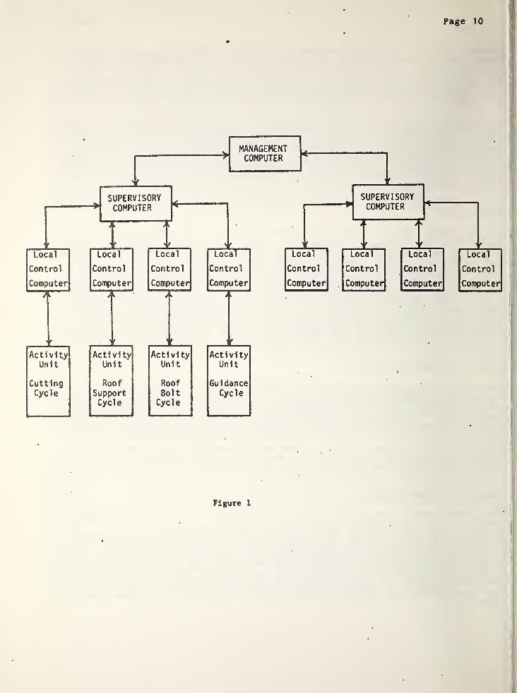
The most common proc.ess control organization is the hierarchicalorganization. As applied to the AES, it could be shown as Figure 1 . Thelowest level is occupied by the function controller that directly regulatesa single activity on the mining machine, such as the cutting cycle. Thislowest level controller carries out sequential operations and interacts witha variety of sensors and actuators. Interfaces at this level are termed"local instrumentation" interfaces. The next higher level is responsiblefor coordinating several related activities for scheduling operations, andfor optimizing the machine performance. This is the system controlinterface.
Page 10
* -
Local
Control
Computer
A
- t ..Activity
Unit
CuttingCycle
j
SUPERVISORYCOMPUTER
Local
Control
Computer
Local
Control
Computer
MANAGEMENTCOMPUTER
—Local
Control
Computer
Activity Activity ActivityUnit Unit Unit
Roof Roof GuidanceSupport Bolt CycleCycle Cycle
Local
Control
Computer
SUPERVISORYCOMPUTER
Local
Control
Computer
Local
Control
Computer
Local
Control
Computer
Figure 1
i
Page 1
1
At the top level is the corporate control computer. While not presently a
part of the AES, this level in the hierarchy could be added to control twoor more AES machines and to make current information about mining operationsavailable to management. Additionally, with these interfaces it would bepossible to provide remote diagnosis for AES maintenance from a centralsite. While this level in the hierarchy will not be considered in thisreport, it should be pointed out that specifications for the interfaces atthis level are well developed being either in the draft stage or alreadyapproved as formal standards. US6M may wish at some future time- toinvestigate this additional opportunity.
The hierarchical organization represents an advanced automation system sinceit is concerned not only with the physical control of the activities butalso with its management (the gathering and application of both machineactivity and business information for decision-making). The operations atthe lowest level (of regulating the activities and watching for systemfailures) are the simplest and must be done most frequently. The optimizingand scheduling tasks at the higher levels are much more complex but theymust be done less frequently. This consideration will be important fordeciding on a network architecture and for choosing the appropriatestandards for the various interfaces.
Communications Network
The communications network for the AES modular control system is a criticalcomponent. Its architecture must be chosen not only on the basis ofperformance but also on reliability, maintainability, flexibility, and cost.There are three common types of architecture to consider for local controlapplications (as distinct from general communications networks.)
The central or "star" structureThe distributed or "bus" structureThe "ring” structure.
All of these structures assume that there are computers in the system withresources to be each other to best meet the objectives of the system. Thesecomputers are referred to as "nodes" in the communications network, and thearchitecture determines how the nodes communicate within the network. Forthe AES, the objective of the network must be to effectively control thehardware involved in the coal extraction process. While the hardwareconfiguration is well known, the architecture of the AES control system hasyet to be detailed. For this reason it is difficult to make recommendationsfor appropriate interface standards. However, by examining the threearchitectures mentioned and analyzing the applicability of various interfacestandards to these architectures, much can be learned for use with the AES.The next two sections provide this analysis first for the localinstrumentation interfaces and secondly for the system control levelinterfaces.

Page 12
STANDARDS FOR THE LOCAL INSTRUMENTATION INTERFACE
The specifications for the AES control system describe four functions whichwill be automated* These include the cutting cycle, roof support cycle,roof bolting cycle, and guidance. The modular nature of the function beingautomated clearly points to a similar organization of the local controlsystem. There are many advantages to designing modularity into a complexcontrol system such as this, including the ease of adding or changingsubsystems and the ability to accomodate design changes. Standards foe themany local instrumentation interfaces here are well defined. A designer isable to utilize existing standards for the mechanical, electrical andprocedural aspects of the interface. Alternatively, he may choose one ofthe complete instrumentation package standards which encompass all of theseaspepts. This section will present a view of the proper application ofinterface standards at the instrumentation level. It will show where a
standard is useful and the benefits and limitations of its selection.Summary data sheets on each of the standards mentioned are included at theend of the section, and complete technical descriptions, are given inAppendix B.
Figure 2 serves to illustrate theapplicability of interface standards toa modular functional controller. Foursuch controllers are envisioned for theAES with each being implemented via a
microcomputer or other programmablelogic. The module is seen as aself-sufficient activity which, wheninitiated with the necessary parameters,can carry out its task withoutcommunication with other modules.
Operations within the module areperformed quite frequently with theremote actuators and sensorscommunicating with the localmicrocomputer via voltages, or currents.The actual form of that communicationcan be classified first as being analogor digital. Other considerationsinclude whether the communication isbidirectional, the speed at which theinformation must be transmitted, itsvolume, and the degree of error whichcan be tolerated. The exact choice ofstandards depends upon all of thesefactors.
Similarly, sensors and actuators can be classified as analog or digital.Shaft encoders and solenoid valves are primarily digital while motors andpotentiometers are usually analog in nature.
Page 13
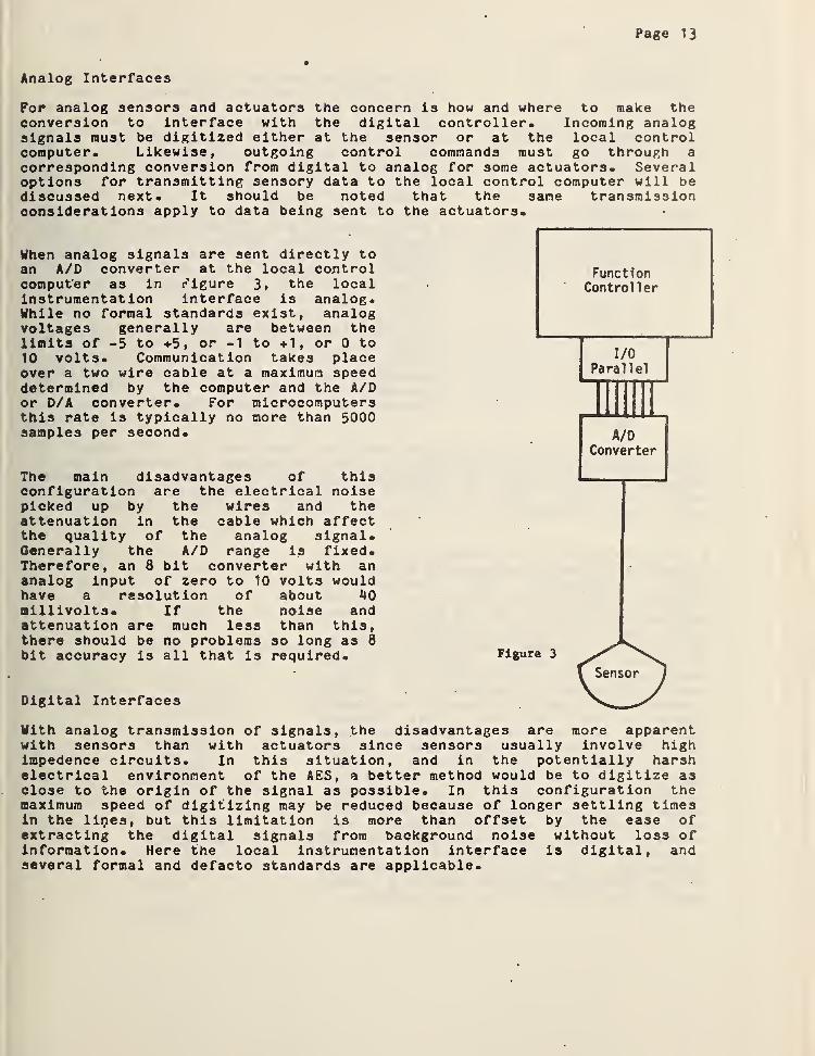
Analog Interfaces
For analog sensors and actuators the concern is how and where to make theconversion to interface with the digital controller. Incoming analogsignals must be digitized either at the sensor or at the local controlcomputer. Likewise, outgoing control commands must go through a
corresponding conversion from digital to analog for some actuators. Severaloptions for transmitting sensory data to the local control computer will bediscussed next. It should be noted that the sane transmissionconsiderations apply to data being sent to the actuators.
When analog signals are sent directly toan A/D converter at the local controlcomputer as in Figure 3, the localinstrumentation interface is analog.While no formal standards exist, analogvoltages generally are between thelimits of -5 to +5, or -1 to +1, or 0 to10 volts. Communication takes placeover a two wire cable at a maximum speeddetermined by the computer and the A/Dor D/A converter. For microcomputersthis rate is typically no more than 5000samples per second.
The main disadvantages of thisconfiguration are the electrical noisepicked up by the wires and theattenuation in the cable which affectthe quality of the analog signal.Generally the A/D range is fixed.Therefore, an 8 bit converter with ananalog input of zero to 10 volts wouldhave a resolution of about 40millivolts. If the noise andattenuation are much less than this,there should be no problems so long as 8bit accuracy is all that is required.
Digital Interfaces
With analog transmission of signals, the disadvantages are more apparentwith sensors than with actuators since sensors usually involve highimpedence circuits. In this situation, and in the potentially harshelectrical environment of the AES, a better method would be to digitize asclose to the origin of the signal as possible. In this configuration themaximum speed of digitizing may be reduced because of longer settling timesin the lines, but this limitation is more than offset by the ease ofextracting the digital signals from background noise without loss ofinformation. Here the local instrumentation interface is digital, andseveral formal and defacto standards are applicable.

Page 14
FunctionController
Figure 4
Two basic options for digital transmissionare possible, parallel or serial. Figure 4
considers the parallel case. Transmissionhere is termed bit parallel, byte serial.Each byte is a finite number of bits, often4, 8 or 16. Bytes are coded in a certainconvention such as Binary Coded Decimal(BCD) or American Standard Code forInformation Interchange (ASCII). The BCDparallel interface is a defacto standardfound commonly with thumbwheel switches -anddigital readout devices. The ElectronicIndustries Association (EIA) has publishedRS-408 originally to define the bitparallel, byte serial interface between apaper tape reader and the controller of anumerically controlled machine tool. RS-408is capable of transmitting any 7 or 8 bitcode like ASCII and certainly may berelevant to the AES project.- Electricalspecifications with either BCD or RS-408generally conform to the defacto TTLconvention of zero and 5 volts.
A minor disadvantage of the digital parallel interface is the number ofwires associated with each sensor. A multi-wire cable is necessary and isexpensive for long runs. For Instance, to transmit two digits in BCD formatwould require at least 11 lines (8 for data, 2 for control and one commonwire). Also transmission in bit parallel form is generally unidirectional.
A great reduction in the number of wires canbe made by transmitting the data serially as;
shown in Figure 5* LSI circuits areavailable commercially which can convertparallel signals, such as the A/D converteroutput into serial for transmission over asingle pair of wires. The message rate isof course much slower than with paralleltransmission. Undoubtably the most widelyused interface standard for serialtransmission of digital data in the UnitedStates is the RS 232-C. This standardspecifies not only the electrical andfunctional characteristics of the interfacebut the mechanical plug connection as well.With RS 232-C a wide range of options areavailable to the user. For Instance,communication can be one way (simplex), twoway (duplex) or two way simultaneous (fullduplex). .Although this latter form requiresa minimum of four wires, it allowsconsiderable flexibility in communicatingwith an intelligent device such as a "smartsensor" like the Coal Interface Detector.
Figure S

Page 15
If a functional controller can communicate in this fashion with each of itssensors and actuators, it can also perform automatic calibration anddiagnostic checking. Maintenance for the AES as a whole would besimplified, and productivity objectives could be more easily achieved.
Serial transmission data rates are expressed in bits per second and canrange up to 20,000 bps with RS 232-C over 12 meter cable lengths. Keepingin mind this is bit serial, transmission in this mode is often too slow forsome applications. A successor to RS 232-C, designated as EIA standardRS-449, will enable serial transmission at rates up to 10 million bps anddistances up to 1000 meters.
Discussion of serial bit transmission would not be complete without mentionof the 20 raa current loop interface. Bits are represented by the flow ofcurrent in the line as contrasted to RS 232-C which uses voltage levels.The current loop interface is very widely used. Although not documented asa formal standard, it is nevertheless quite useful for low speed,asynchronous transmission. It has good noise immunity and performs overlong distances of simple twisted pair lines.
Table 1 summarizes the characteristics, standards, benefits and limitationsof the several options discussed for the AES local instrumentationinterfaces to actuators and sensors.
Table 1 - Comparison of Data Transmission Methods
Transmission Available Maximum Maximum Noise WireMethod Standards Distance Speed Immunity Volume
Analog none 30 ra 5 K hertz poor low
Digital BCD or TTL 15 1 K char/sec fair highParallel RS - 408 10 10 K char/sec fair high
Digital RS 232-C 12 20 K bits/sec good lowSerial RS 449 1000 10 M bits/sec good low
20 MA loop 1000 1 K bits/sec excel low
Page 16
Summary Data Sheets
The following pages list summary data on the various standards mentioned inthis section on the Local Instrumentation Interface* Included here are thefollowing
:
EIA RS 232-CEIA RS 408EIA RS 449ANSI X3.16 (ASCII Serial)ANSI x3-25 (ASCII Parallel)Parallel Interface (TTL)20 MA Current Loop
Page 17
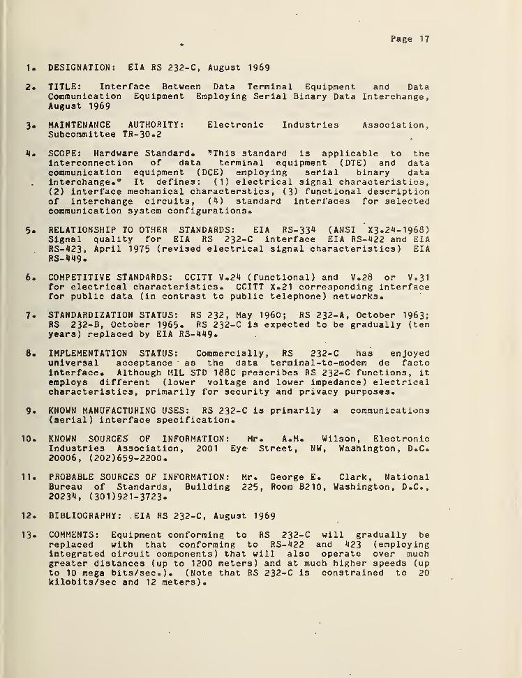
1. DESIGNATION: EIA RS 232-C, August 1969
2. TITLE: Interface Between Data Terminal Equipment and DataCommunication Equipment Employing Serial Binary Data Interchange,August 1969
3 . MAINTENANCE AUTHORITY: Electronic Industries Association,Subcommittee TR-30.2
4. SCOPE: Hardware Standard. "This standard is applicable to theinterconnection of data terminal equipment (DTE) and datacommunication equipment (DCE) employing serial binary datainterchange." It defines: (1) electrical signal characteristics,( 2 ) interface mechanical characterstics
, ( 3 ) functional descriptionof interchange circuits, (4) standard interfaces for selectedcommunication system configurations.
5. RELATIONSHIP TO OTHER STANDARDS: EIA RS-334 (ANSI X3. 24-1968)Signal quality for EIA RS 232-C interface EIA RS-422 and EIARS-423, April 1975 (revised electrical signal characteristics) EIARS-449.
6 . COMPETITIVE STANDARDS: CCITT V.24 (functional) and V.28 or V • 3
1
for electrical characteristics. CCITT X.21 corresponding interfacefor public data (in contrast to public telephone) networks.
7. STANDARDIZATION STATUS: RS 232, May I960; RS 232-A, October 1963;RS 232-B, October 1965. RS 232-C is expected to be gradually (tenyears) replaced by EIA RS-449*
8 . IMPLEMENTATION STATUS: Commercially, RS 232-C has enjoyeduniversal acceptance as the data terminal-to-raodem de factointerface. Although MIL STD 188C prescribes RS 232-C functions, itemploys different (lower voltage and lower impedance) electricalcharacteristics, primarily for security and privacy purposes.
9. KNOWN MANUFACTURING USES: RS 232-C is primarily a communications(serial) interface specification.
10. KNOWN SOURCES OF INFORMATION: Mr. A.M. Wilson, ElectronicIndustries Association, 2001 Eye Street, NW, Washington, D.C.20006, (202)659-2200.
11. PROBABLE SOURCES OF INFORMATION: Mr. George E. Clark, NationalBureau of Standards, Building 225, Room B210, Washington, D.C.,20234, ( 301 ) 921-3723-
12. BIBLIOGRAPHY: EIA RS 232-C, August 1969
13« COMMENTS: Equipment conforming to RS 232-C will gradually bereplaced with that conforming to RS-422 and 423 (employingintegrated circuit components) that will also operate over muchgreater distances (up to 1200 meters) and at much higher speeds (upto 10 mega bits/sec.). (Note that RS 232-C is constrained to 20kilobits/sec and 12 meters).
Page 18
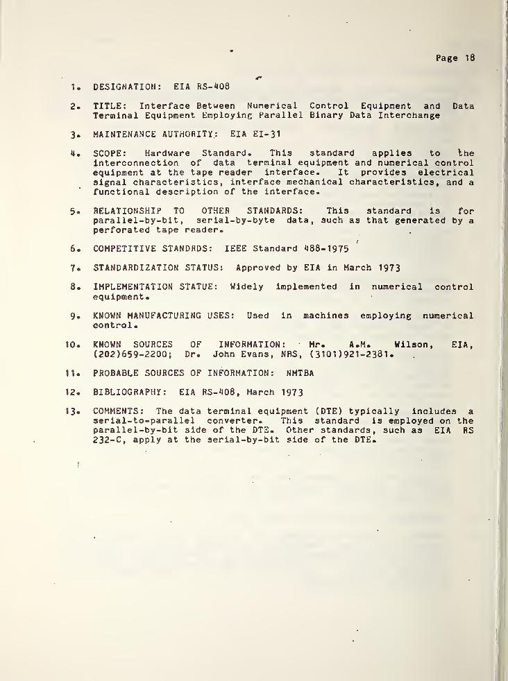
1. DESIGNATION: EIA RS-408
2. TITLE: Interface Between Numerical Control Equipment and DataTerminal Equipment Employing Parallel Binary Data Interchange
3. MAINTENANCE AUTHORITY; EIA El- 3
1
4* SCOPE: Hardware Standard- This standard applies to theinterconnection of data terminal equipment and numerical controlequipment at the tape reader interface. It provides electricalsignal characteristics, interface mechanical characteristics, and a
functional description of the interface.
5- RELATIONSHIP TO OTHER STANDARDS: This standard is forparallel-by-bit, serial-by-byte data, such as that generated by aperforated tape reader.
6- COMPETITIVE STANDRDS: IEEE Standard 488-1975
7. STANDARDIZATION STATUS: Approved by EIA in March 1973
8. IMPLEMENTATION STATUE: Widely implemented in numerical controlequipment.
9- KNOWN MANUFACTURING USES: Used in machines employing numericalcontrol
•
10. KNOWN SOURCES OF INFORMATION: Mr. A.M. Wilson, EIA,(202)659-2200; Dr. John Evans, NBS, ( 3101 ) 921-238 1
.
11. PROBABLE SOURCES OF INFORMATION: NMTBA
12. BIBLIOGRAPHY: EIA RS-408, March 1973
13« COMMENTS: The data terminal equipment (DTE) typically includes aserial-to-parallel converter. This standard is employed on theparallel-by-bit side of the DTE. Other standards, such as EIA RS2 32-C, apply at the serial-by-bit side of the DTE.
i
Page 19
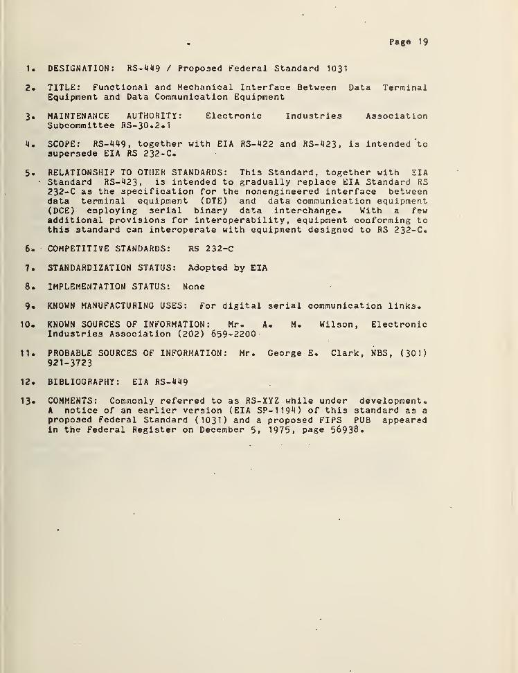
1. DESIGNATION: RS-449 / Proposed Federal Standard 1031
2. TITLE: Functional and Mechanical Interface Between Data TerminalEquipment and Data Communication Equipment
3. MAINTENANCE AUTHORITY: Electronic Industries AssociationSubcommittee RS-30.2.1
4. SCOPE: RS-449 ,together with EIA RS-422 and RS-423, is intended ‘to
supersede EIA RS 232-C.
5. RELATIONSHIP TO OTHER STANDARDS: This Standard, together with EIA• Standard RS-423> is intended to gradually replace EIA Standard RS232-C as the specification for the nonengineered interface betweendata terminal equipment (DTE) and data communication equipment(DCE) employing serial binary data interchange. With a fewadditional provisions for interoperability, equipment conforming tothis standard can interoperate with equipment designed to RS 232-C.
6. COMPETITIVE STANDARDS: RS 232-C
7. STANDARDIZATION STATUS: Adopted by EIA
8. IMPLEMENTATION STATUS: None
9. KNOWN MANUFACTURING USES: For digital serial communication links.
10. KNOWN SOURCES OF INFORMATION: Mr. A. M. Wilson, ElectronicIndustries Association (202) 659-2200
11. PROBABLE SOURCES OF INFORMATION: Mr. George E. Clark, NBS, (301)921-3723
12. BIBLIOGRAPHY: EIA RS-449
13* COMMENTS: Commonly referred to as RS-XYZ while under development.A notice of an earlier version (EIA SP-1194) of this standard as aproposed Federal Standard (1031) and a proposed FIPS PUB appearedin the Federal Register on December 5, 1975, page 56938*

Page 20
1. DESIGNATION: FIPS PUB 17-1971/ANSI X3- 1 6- 1 966
2* TITLE: Character Structure and Character Parity Sense forSerial-by-Bit Data Communication in ASCII (FIPS PUB 1/ANSIX3.K-1968)
3« SCOPE: Hardware Standard. This standard specifies the characterstructure and sense of character parity for serial-by-bit,serial-by-character synchronous and asynchronous data communicationin ASCII (FIPS PUB 1, ANSIC X3.4-1968). This standard applies togeneral information interchange at the interface between dataprocessing terminal equipment and the data communication equipment.
*4. RELATIONSHIP TO OTHER STANDARDS: This standard is animplementation of the 7-bit code of ASCII (FIPS PUB 1/ANSIX3.4-1968). It is used at interfaces such as EIA RS 232-C. Thecompanion standard FIPS PUB 18/ANSI X3-25-1968 is for' characterstructures using parallel-by-bit data communication. Subsets, suchas EIA RS-358, can use the structure of this standard.
5. COMPETITIVE STANDARDS: Proprietary structures for communicatingnon-ASCII codes, such as 6-bit Teletypesetter or 8-bit EBCDIC
6* STANDARDIZATION STATUS: The ANSI standard X 3 • 1 6 was approved onAugust 19, 1966; FIPS PUB 17, adopting in its entirety that ANSIstandard, was approved on October 1, 1971.
7. IMPLEMENTATION STATUS: Widely implemented in communication systemsand ADP terminal devices.
8. KNOWN MANUFACTURING USES:
9. KNOWN SOURCES OF INFORMATION: Mr. John L. Little, NBS,(301)921-3723; Mr. George E. Clark, NBS, (301)921-3723.
10. PROBABLE SOURCES OF INFORMATION: Teletype Corporation
11. BIBLIOGRAPHY: FIPS PUB 17-1971/ANSI X3. 16-1966
12. COMMENTS: This standard specifies odd parity for synchronous datacommunication and even parity for asynchronous data communication.It does not specify the bit sequence, which is given in FIPS PUB16/ANSI X3. 15-1966.
Page 21
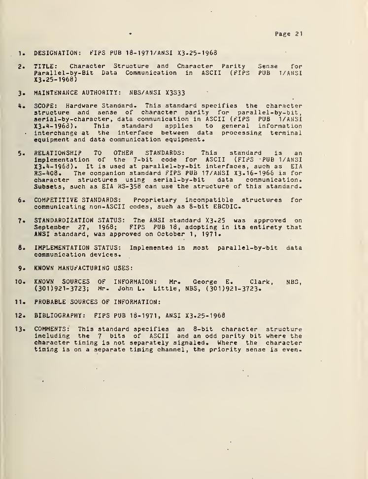
1. DESIGNATION: FIPS PUB 18-1971/ANSI X3-25-1963
2. TITLE: Character Structure and Character Parity Sense forParallel-by-Bit Data Communication in ASCII (FIPS PUB 1/ANSIX3* 25-1968)
3. MAINTENANCE AUTHORITY: NBS/ANSI X3S33
l). SCOPE: Hardware Standard. This standard specifies the characterstructure and sense of character parity for parallel-by-bit,serial-by-character, data communication in ASCII (FIPS PUB 1/ANSIX3.4-1963). This standard applies to general informationinterchange at the interface between data processing terminalequipment and data communication equipment.
5. RELATIONSHIP TO OTHER STANDARDS: This standard is animplementation of the 7-bit code for ASCII (FIPS -PUB 1/ANSIX3.4-1963). It is used at parallel-by-bit interfaces, such as EIARS-408. The companion standard FIPS PUB 17/ANSI X3-16-1966 is forcharacter structures using serial-by-bit data communication.Subsets, such as EIA RS-358 can use the structure of this standard.
6. COMPETITIVE STANDARDS: Proprietary incompatible structures forcommunicating non-ASCII codes, such as 8-bit EBCDIC.
7 . STANDARDIZATION STATUS: The ANSI standard X3.25 was approved onSeptember 27, 1968; FIPS PUB 18, adopting in its entirety thatANSI standard, was approved on October 1, 1971*
8. IMPLEMENTATION STATUS: Implemented in most parallel-by-bit datacommunication devices.
9. KNOWN MANUFACTURING USES:
10 . KNOWN SOURCES OF INFORMAION : Mr. George E. Clark, NBS,( 301 ) 92 1- 3723 ;
Mr. John L. Little, NBS, (301 )921-3723«
11 . PROBABLE SOURCES OF INFORMATION:
12 . BIBLIOGRAPHY: FIPS PUB 18-1971, ANSI X3-25-1968
13« COMMENTS: This standard specifies an 8-bit character structureincluding the 7 bits of ASCII and an odd parity bit where thecharacter timing is not separately signaled. Where the charactertiming is on a separate timing channel, the priority sense is even.
Page 22
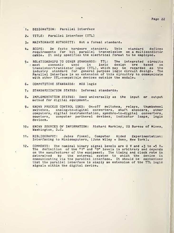
1. DESIGNATION: Parallel Interface
2. TITLE: Parallel Interface (TTL)
3. MAINTENANCE AUTHORITY: Not a formal standard.
4. SCOPE: De facto hardware standard. This standard definesrequirements for bit parallel transmission on a multicondictorcable. It only specifies the electrical format to be employed.
5. RELATIONSHIPS TO OTHER STANDARDS: TTL: The integrated circuits• most commonly used in logic design are based ontransistor/transistor logic (TTL), which may be regarded as theindustry standard for general purpose logic circuit design. TheParallel Interface is an extension of this circuitry to communicatewith other TTL-compatible devices outside the module.
6. COMPETITIVE STANDARDS: MOS logic
7. STANDARDIZATION STATUS: Informal standards.
8. IMPLEMENTATION STATUS: Used universally as the input or outputmethod for digital equipment.
9. KNOWN PROCESS CONTROL USES: On-off switches, relays, thumbwheelswitches, analog-to-digital converters, shaft encoders, othercomputers, digital instrumentation, synchro-to-digital converters,counters, computer periheral devices, indicator lamps, logicdevices.
10. KNOWN SOURCES OF INFORMATION: Richard Markley, US Bureau of Mines,Washington, D.C.
11. BIBLIOGRAPHY: Jules Finkel, Computer Aided Experimentation:Interfacing to Minicomputers, (John Wiley Sons, New York).
12. COMMENTS: The nominal binary signal levels are 0 V and +3 to +5 V.The definition of the "1" and "0" levels is arbitrary and dependson the manufacturer of the equipment. The timing and clock rate isdetermined by the external system to which the device iscommunicating via the parallel interface. It should be emphasizedthat the parallel interface is simply an extension of the TTL logicsignals within the digital device.
Page 2
3
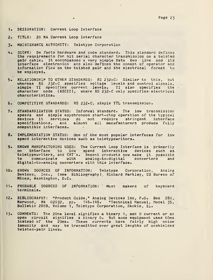
1* DESIGNATION: Current Loop Interface
2. TITLE: 20 MA Current Loop Interface
3. MAINTENANCE AUTHORITY: Teletype Corporation
4. SCOPE: De facto hardware and code standard. This standard definesthe requirements for bit serial character transmission on a twistedpair cable. It encompasses a very simple Data Bus line and itsinterface electronics and also defines the conept of operator andinformation flow on the twisted pair and the electrical format tobe employed.
5. RELATIONSHIP TO OTHER STANDARDS: RS 232-C: Similar to this, butwhereas RS 232-C specifies voltage levels and control signals,simple TI specifies current levels. TI also specifies thecharacter code (ASCII), where RS 232-C only specif ies- electricalcharacteristics.
6. COMPETITIVE STANDARDS: RS 232-C, simple TTL transmission.
7. STANDARDIZATION STATUS: Informal standard. The low transmissionspeeds and simple asychronous start-stop operation of the typicaldevices it services do not require stringent interfacespecifications, and almost all manufacturers produce fullycompatible interfaces.
8* IMPLEMENTATION STATUS: One of the most popular interfaces for lowspeed interactive devices such as teletypewriters.
9.
KNOWN MANUFACTURING USES: The Current Loop Interface is primarilyon interface to low speed interactive devices such asteletypewriters, and CRT's. Recent products now make it possibleto communicate with analog-to-digital converters anddigital-to-analog converters with this interface.
10. KNOWN SOURCES OF INFORMATION: Teletype Corporation, AnalogDevices, Inc., (see Bibliography), Richard Markley, US Bureau ofMines, Washington, D.C.
11. PROBABLE SOURCES OF INFORMATION: Most makers of keyboardterminals.
12. BIBLIOGRAPHY: "Product Guide," Analog Devices Inc, P.0* Box 280,Norwood, MA 02032, pp. 146-148. "Technical Manual, Model 35,Bulletin 280B, Volume 1, Teletype Corporation, Skokie, IL.
13* COMMENTS: The 20ma level signifies a binary 1, and 0 current or anopen circuit signifies a binary 0. But some equipment uses 60maInstead of the 20ma. These currents have fairly high noiseimmunity and may be transmitted over great lengths of unshieldedtwisted-pair lines.
Page 24
STANDARDS FOR THE SYSTEM CONTROL INTERFACE
While the functions of the system controller are fairly well defined, suchis not the case with the architecture of the communications network by wnic.h
the system controller coordinates and integrates the four AES functions. Itshould be realized that interfaces at the system level are generally .morecomplex than at the local instrumentation level. In addition to thephysical, electrical, and procedural aspects of an interface, protocolbecomes an important factor at the system control level for governing theflow of data across the communications links to the functional controllers.
Mentioned previously were three communications network organizations thatare applicable to the AES development: the "star”, the "bus", and the"ring." As different as the architectures is the difference in theirrequirements for interface standards. Each will be examined to identify theappropriate interface standards which apply. Summary data sheets for thesestandards are included at the end of this section while Appendix B includesa comprehensive discussion on each standard.
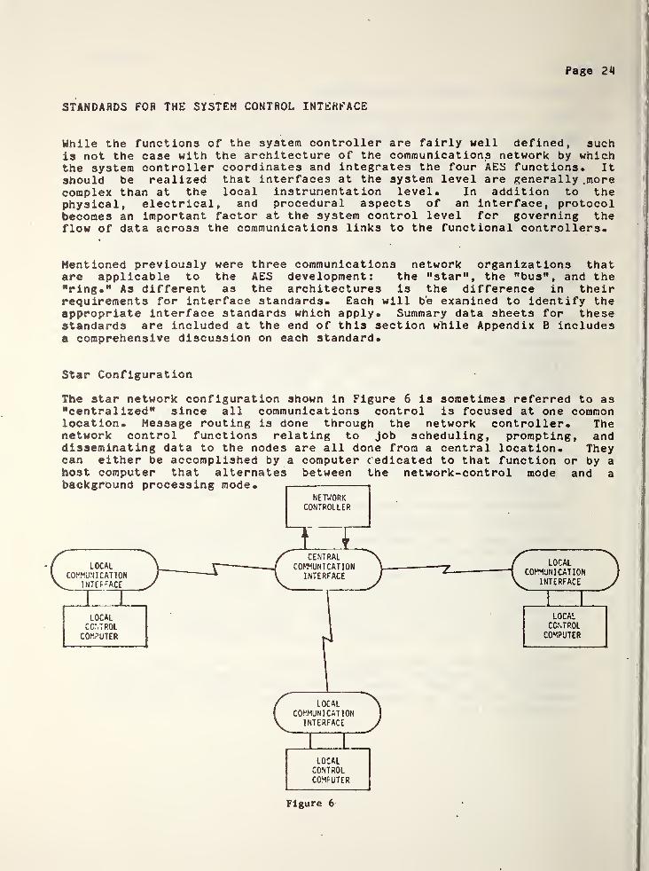
Star Configuration
The star network configuration shown in Figure 6 is sometimes referred to as"centralized" since all communications control is focused at one commonlocation. Message routing is done through the network controller. Thenetwork control functions relating to job scheduling, prompting, anddisseminating data to the nodes are all done from a central location. Theycan either be accomplished by a computer c'edicated to that function or by ahost computer that alternates between the network-control mode and a
Figure 6
Page 25
Because network control takes place at one location, the network controlproblem is greatly simplified. This type of network is directly applicablein a hierarchical process control organization since supervisory functionscan be done by the central node while it manages the network.Communications with the functional controllers is concerned with taskinitiation, status checking, t etc. Neither data rate nor volume isdemanding. A bit serial, two way form of communication such as allowed byRS 232-C would suffice. If the cable length limit of 12 meters or the bitrate limit of 20 kilobits per second preclude the use of HS 232-C, seriousconsideration should be given to its successor, HS-449. In the unbalancedmode this will allow cable runs up to 60 meters and bit rates up to 100kilobits. In the balanced mode *<3-449 can operate to 1200 meters and 10
megabits per second.
The main disadvantage of the star network is that each conmunnications lineapplies to just one computer. Therefore, for two local control computers tocommunicate, their traffic must be switched through the control node. Thestar structure does not allow direct communications between outer nodes. Asthe need for dynamic interaction between outer nodes increases, more demandsare made on the central network controller, and it may introduce more delaysthan can be tolerated in the process.
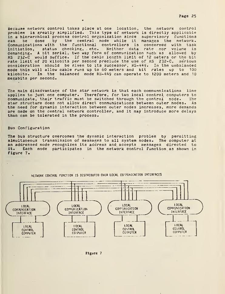
Bus Configuration
The bus structure overcomes the dynamic interaction problem by permittingsimultaneous transmission of messages to all system nodes. The computer atan addressed node recognizes its address and accepts messages directed toit. Each node participates in the network control function as shown inFigure 7.
NETWORK CONTROL FUNCTION IS DISTRIBUTED OVER LOCAL COMMUNICATION INTERFACES
Figure 7
Page 26
In general, if properly designed, distributed networks such as this offerincreased reliability since a failure at one node does not necessarilyaffect the rest of the network. In some cases, a bus structure mayfacilitate testing since the testing device itself can be attached while theentire system is functioning. Similiarly, additional functional modules caneasily be added to the system controller. No hardware changes arenecessary. Only the software for the system controller need be modified.
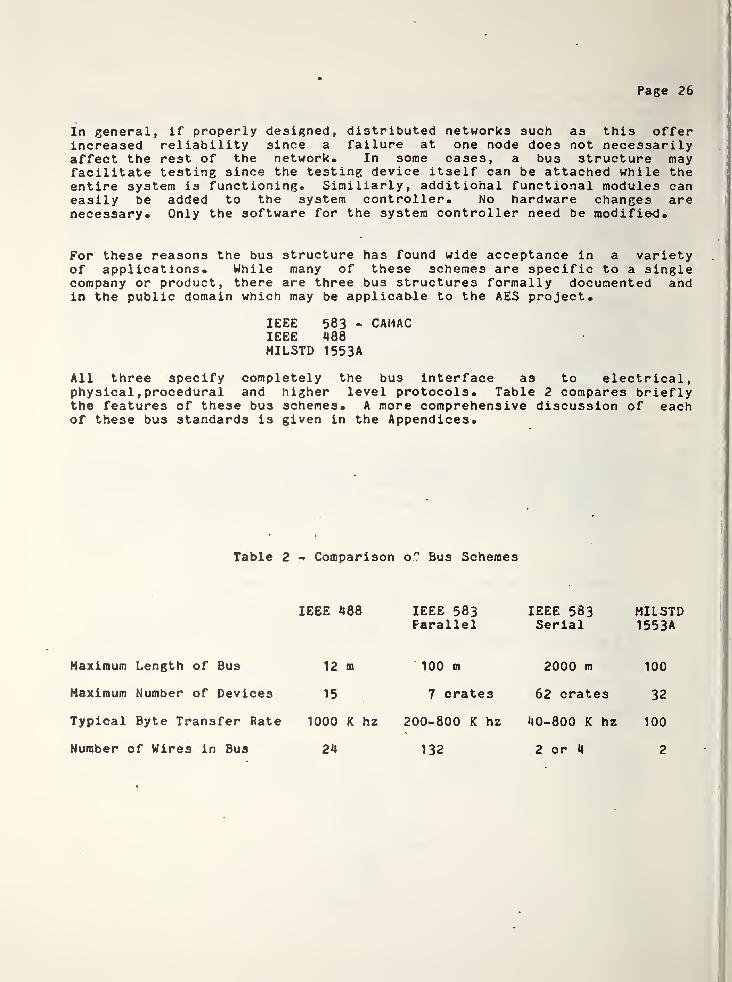
For these reasons the bus structure has found wide acceptance in a varietyof applications. While many of these schemes are specific to a singlecompany or product, there are three bus structures formally documented andin the public domain which may be applicable to the AES project.
IEEE 583 - CAMACIEEE 488MILSTD 1553A
All three specify completely the bus interface as to electrical,physical
,procedural and higher level protocols. Table 2 compares briefly
the features of these bus schemes. A more comprehensive discussion of eachof these bus standards is given in the Appendices.
Table 2 - Comparison o~ Bus Schemes
IEEE 488 IEEE 583 IEEE 583 MILSTDParallel Serial 1553A
Maximum Length of Bus 12 m 100 m 2000 m 100
Maximum Number of Devices 15 7 crates 62 crates 32
Typical Byte Transfer Rate 1000 K hz 200-800 K hz 40-800 K hz 100
Number of Wires in Bus 24 132 2 or 4 2

Page 27
The main problems with bus structures are that they are difficult to controland that they require complex communications - network interfaces at eachnode* Because of the generality of a bus structure, control protocolbecomes complicated and priority determination becomes difficult.Contention for the bus may be resolved by giving priority to thesesubsystems which are physically closest to one end of the bus - this is thescheme used to resolve contention on the Digital PDP-11 "Unibus. " Anothermethod for establishing priorities is to install a bus controller whichpolls the subsystems at pre-programmed rates to offer them the use of thebus. The polling method eliminates all contention problems. This is thecase with the three formal standards.
Ring Configuration
The third network is the loop or "ring" network illustrated by Figure 8 inwhich all traffic derived from the nodes is carried by a loop circuit. Oneof its main advantages is that it allows priority determination without a
master computer. One method by which it can achieve this in a system withfixed message lengths is to employ "lazy susan" time multiplexing, in whichany node can add a message to any empty circulating slot. The ring networkis suitable in a process control system organization where there is completedistribution of functions and where much data must be dynamically exchangedamong nodes. The nodes may have control tasks distributed to them as withthe AES, or computer function tasks such as distributing the process I/O,man-machine interface I/O, stored paramters, and the computing functions.
Because each node participates in message forwarding, a failure in any nodecould cause complete system failure. Another disadvantage, is that asmessages circulate, delays occur in each node, so that this type of networkmay not be applicable in time critical applications.
LOCALCONTROLCOMPUTER
Figure 8

Page 28
Data Link Control Procedures
To this point the discussion has centered on the mechanical, electrical andprocedural aspects of a communications interface- This covers how the datais transmitted and how it is interpreted by the receiver- Still to beanswered is the control of the communication process - the protocol thatassures that the data is sent to the proper destination and that it isreceived without error- To do this we must look at the communications linkand the control procedures that govern the process.
Anyone who has worked with automation equipment realizes the consequences oferrors in the control data. Whether they be caused by data being sent tothe wrong location, electrical noise, loose connections, or corrodedcontacts, the results are the same - lost production and often a damagedmachine. Consider, then, the control of automated functions on board thecoal extraction machine or possibly the control of several AES machines froma central point. In such sophisticated equipment, where malfunctions may behazardous to human operators, there is no room for error. It is in thesesensitive communications areas that link control protocol becomes essential.
Use of a link to transmit data involves not only the transmission of databut the transmission of "control" information which is used by the terminalson the link to correctly handle individual messages, to synchronizeoperations, and to detect and recover from errors.
Specifically, this control information should implement at least thefollowing functional requirements:
transmission initiationtransmission controlerror checkingerror recovery .
transmission termination
Two general types of data link control procedures may be identified: (1)the character-oriented, in which defined "control" characters delimitinformation fields and convey logical signalling information; and (2) thebit-oriented, in which bit strings of varying length delimit fields andconvey control information. Bit-oriented procedures are recognized asinherently more efficient in terms of bandwidth, but prior to the maturationof microcomputer technology, were felt to be too computationally demandingfor widespread use.
Character Oriented Protocols
The procedures of American National Standard X3-28-1976 treat the bit streamas a sequence of characters. This standard utilizes the ten communicationscontrol characters of the ASCII (ANSI X3-**) character set to define linkcontrol and specify procedures for establishing, using and terminating alink connection.
Page 29
A problem with X3«28 is that the standard, rather than giving a singlesolution to the problem of link control, is essentially a list of approvedalternative solutions. Ten subcategories of establ ishnent/terminat ionprocedures are specified and fourteen subcategories of message transferprocedures. Thus, there are 140 possible systems which are standardized by
X3.26. However, only about 80 of these can actually be realized, and mostof these systems are incompatible with each other.
Bit Oriented Protocols
Bit oriented procedures have been advanced both because of their inherentlyhigher efficiency (in terms of line utilization) and as a way to "startfresh" from the maze of different configurations in X3«26. Until recently,these procedures were limited due to the computational complexity offraming, "bit-stuffing" and error detection computing. But the newmicroprocessor technology has opened the way for the widespread applicationof this type of procedure.
The American National Standards Institute is currently developing a proposedstandard called Advanced Data Communication Control Procedures (ADCCP) whichapproaches the same problem as X3-28-1976* Though a number of years indevelopment by ANSI the new bit-oriented data link control procedure isfinally near completion. The unit of transmission in ADCCP is a frame, andall transmissions on the link utilize this format. ADCCP is basicallydivided into three parts. The first part includes the frame formatspecifications and a description of the 16 bit algorithm used for errordetection in the frame check sequence. The second part describes the modesof operation and repertoire of commands and responses* The final part ofADCCP deals with the six different classes of procedure that are allowedunder the standard* A user would choose the one best suited to his mode ofoperation*
ADCCP entails three different methods of error detection* The 16-bit CyclicRedundancy Check (CRC) polynomial metioned before is used for detectingerrors in transmission. In addition, a response timer is specified for theprimary station, to detect no response from the secondary station. Thesequential numbering of frames also helps detect lost or duplicated frames.
Placing this in terms of what ADCCP means to a user is quite simple. On aserial communications link a user could specify RS 449 for the mechanical,electrical, and procedural aspects of his communication and ADCCP for theprotocol* With this configuration handling the data communications betweenthe AES systems controller and each of the functional controllers, a userwould have the total assurance of good data communications required forremote operation. It has been demonstrated with such a system that one canmomentarily unplug the communication link without introducing errors intothe industrial process. ADCCP handles all of the error detection andretransmission needed to assure error-free end to end communication.
Page 30
Summary Data Sheets
The following pages list summary data on the various standards mentioned inthis section on the System Control Interface* Included here are thefollowing
:
IEEE Standard 488IEEE Standard 583MIL Standard 1553 A
ANSI X3-28ANSI ADCCP

Page 31
1. DESIGNATION: IEEE Standard 488-1975
2 . TITLE: IEEE Standard Digital Interface for ProgrammableInstrumentation
3. MAINTENANCE AUTHORITY: IEEE Instrumentation and Measurement Group
SCOPE: Hardware Standard. This standard applies to interfacesystems used to interconnect both programmable and non-programmable(digital) electronic measuring appartus with other apparatus andaccessories necessary to asemble instrumentation sysytems. It is a
parallel-by-bit, serial-by-byte standard.
5 . RELATIONSHIP TO OTHER STANDARDS: The character coding is basedupon ISO 646-1973, similar to ASCII, FIPS PUB 1, ANSI X3.4-1968.
6. COMPETITIVE STANDARDS: El A RS-408, IEEE Standard 583-1975 (CAMAC)
7 . STANDARDIZATION STATUS: Approved by the IEEE Standards Board onDecember 19, 1974. Development of this standard was coordinatedwith IEC/TC66/WG3* It may become an IEC standard.
8. IMPLEMENTATION STATUS: Implemented in electronic instruments, suchas those made by the Hewlett-Packard Co.
9 . KNOWN MANUFACTURING USES:
10- KNOWN SOURCES OF INFORMATION: Mr. Robert A. Soderman, GeneralRadio Co., (617)396-4400 x608; Mr. Donald C. Loughry,Hewlett-Packard Co., (408)735-1550; Mr. Robert G. Fulks,Omnicorap, 71 N. 12th Place, Phoenix, (6020997-5456.
11 . PROBABLE SOURCES OF INFORMATION: Mr. Barry A. Bell, NBS, (301)921 -2727 .
12 . BIBLIOGRAPHY: IEEE Standard 488-1975
13« COMMENTS: Up to 15 devices may be interconnected on one"party-line" configuration. Cable length is up to 20 meters.Maximum data rate on an any signal line is one megabit per second.This standard is optimized for devices in close proximity (up to 20meters).

Page 32
1. DESIGNATION: IEEE Standard 583-1975
2. TITLE: IEEE Standard Modular Instrumentation and Digital InterfaceSystems (CAMAC)
3. MAINTENANCE AUTHORITY: IEEE Nuclear Instruments and DetectorsCommittees
4. SCOPE: Hardware Standard. "This standard is intended to serve asa basis for a range of modular instrumentation capable ofinterfacing transducers and other devices to digital controllersfor data and control. The standard fully specifies a data bus by
’ means of which instruments and other functional modules cancommunicate with each other, with peripherals, with computers, andwith other external controllers. Data may be transferred eitherbit-serial or byte-serial."
5. RELATIONSHIP TO OTHER STANDARDS: Identical in many respects to IEC482 and 516.
6.
" COMPETITIVE STANDARDS: EIA RS-408, IEEE Standard 488, EIA RS 232-C
?• STANDARDIZATION STATUS: Approved by the IEEE Standards Board onFebruary 27, 1975.
8. IMPLEMENTATION STATUS: Increasingly implemented in laboratorydigital instrumentation equipment, especially that related tonuclear physics and testing.
9. KNOWN MANUFACTURING USES: Aluminum Furnace Control (ALCOA), SteelProcess Control (Inland Steel Co.), Diesel Locomotive Testing (GM),Large Power Semiconductor Testing (GE), Telescope Control and DataGathering (Kitt Peak)
10. KNOWN SOURCES OF INFORMATION: Mr. Dale W. Zobrist, EldecCorporation, (206)743-1313; Mr. Louis Costrell, NBS
,
( 30 1 ) 92 1-25 1 8 ;Mr. Lowell A. Klaisner, Kinetic Systems
Corporation, (615)833-0005.
11. PROBABLE SOURCES OF INFORMATION: IEEE, ERDA, Stanford LinearAccelerator Center, Lawrence Radiation Lab, Berkeley, CA.
12. BIBLIOGRAPHY: IEEE Standard 583-1975; "CAMAC, A ModularStandard," IEEE Spectrum, April 1976, pp. 50-55.
13« COMMENTS: This standard was developed by the ESONE Committee ofEuropean Laboratories and the NIM Committee of ERDA. Data may betransfer '3d byte-serial for high speeds and bit-serial for longdistance.
Page 33
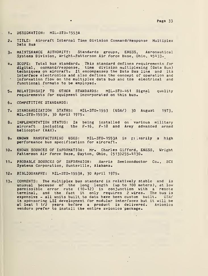
1. DESIGNATION: MIL-STD- 1553A
2. TITLE: Aircraft Internal Time Division Command/Hesponse MultiplexData Bus
3 . MAINTENANCE AUTHORITY: Standards groups, ENESS, AeronauticalSystems Division, Wright-Patterson Air force Base, Ohio, 45433.
4 . SCOPE: Total bus standard. This standard defines requirements fordigital, command/response
,time division multiplexing (Data Bus)
techniques on aircraft. It encompasses the Data Bus line and itsinterface electronics and also defines the concept of operation andinformation flow on the multiplex data bus and the electrical andfunctional formats to be employed.
5. RELATIONSHIP TO OTHER STANDARDS: MIL-STD-461 Signal qualityrequirements for equipment incorporated on this bus.
6 . COMPETITIVE STANDARDS:
7. STANDARDIZATION STATUS: MIL-STD-1553 (USAr) 30 August 1973,MIL-STD- 1553A , 30 April 1975-
8 . IMPLEMENTATION STATUS: Is being installed on various militaryaircraft including the F-16, F-18 and Army advanced armedhelicopter (AAH).
9. KNOWN MANUFACTURING USES: MIL-STD- 1553A is pi Lnarily a highperformance bus specification for aircraft.
10. KNOWN SOURCES OF INFORMATION: Mr. Charles Gifford, ENESS, WrightPatterson Air Force Base, Dayton, Ohio, (513)255-4130.
11. PROBABLE SOURCES OF INFORMAION: Harris Semiconductor Co., SCISystems Corporation, Huntsville, Alabama.
12. BIBLIOGRAPHY: MIL-STD-1553A , 30 April 1975.
13* COMMENTS: The multiplex bus standard is relatively stable and isunusual because of the long length (up to 100 meters), at lowpermissible error rate ( 10 - 12 ) in conjunction with a remoteterminal, and the fact it only requires 2 wires. The bus isexpensive - all units built to data have been custom built. USAFis sponsoring LSI development for modular interfaces but it will beat leat 1 1/2 years before a product is delivered. Avionicsvendors prefer to install the entire avionics package.
Page 34
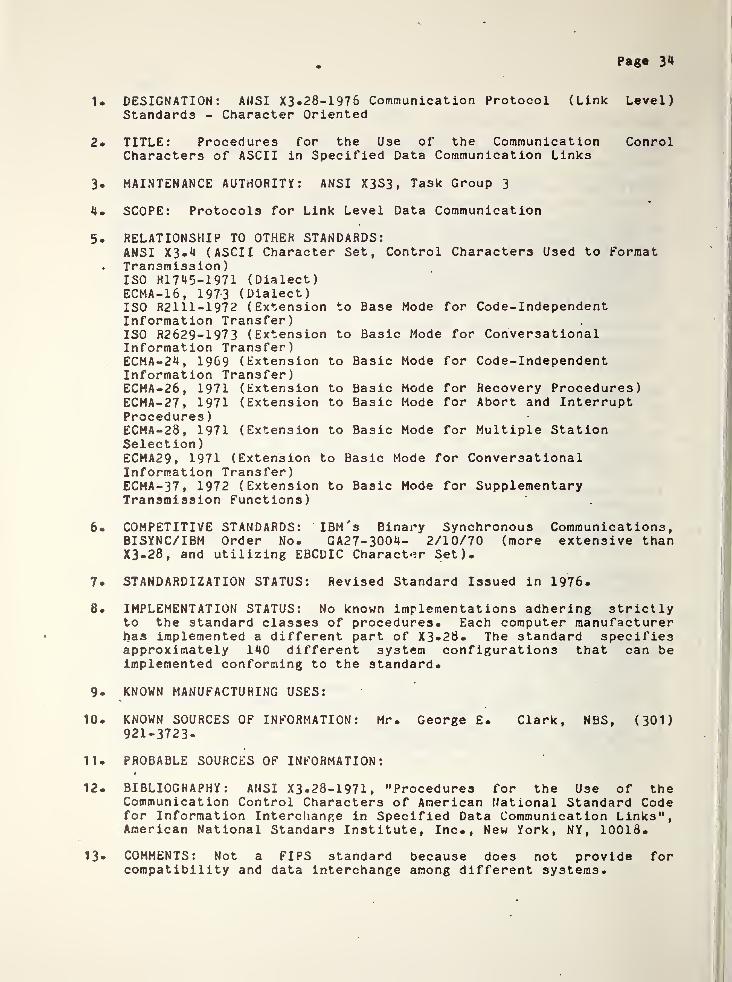
1. DESIGNATION: ANSI X3. 28-1976 Communication Protocol (Link Level)Standards - Character Oriented
2. TITLE: Procedures for the Use of the Communication ConrolCharacters of ASCII in Specified Data Communication Links
3. MAINTENANCE AUTHORITY : ANSI X3S3, Task Group 3
4. SCOPE: Protocols for Link Level Data Communication
5. RELATIONSHIP TO OTHER STANDARDS:ANSI X3.4 (ASCII Character Set, Control Characters Used to Format
. Transmission)ISO HI 7 ^ 5 — 1 97 1 (Dialect)ECMA-16, 1973 (Dialect)ISO R2111-1972 (Extension to Base Mode for Code-IndependentInformation Transfer)ISO R2629-1973 (Extension to Basic Mode for ConversationalInformation Transfer)ECMA-24, 1969 (Extension to Basic Mode for Code-IndependentInformation Transfer)ECMA-26
, 1971 (Extension to Basic Mode for Recovery Procedures)ECMA-27 , 1971 (Extension to Basic Mode for Abort and InterruptProcedures
)
ECMA-28, 1971 (Extension to Basic Mode for Multiple Station
Selection
)
ECMA29, 1971 (Extension to Basic Mode for ConversationalInformation Transfer)ECMA-37, 1972 (Extension to Basic Mode for SupplementaryTransmission Functions)
6. COMPETITIVE STANDARDS: IBM's Binary Synchronous Communications,BISYNC/IBM Order No. GA27-3004- 2/10/70 (more extensive thanX3-28, and utilizing EBCDIC Character Set).
7. STANDARDIZATION STATUS: Revised Standard Issued in 1976.
8. IMPLEMENTATION STATUS: No known implementations adhering strictlyto the standard classes of procedures. Each computer manufacturerhas implemented a different part of X3.28. The standard specifiesapproximately 140 different system configurations that can beimplemented conforming to the standard.
9. KNOWN MANUFACTURING USES:
10. KNOWN SOURCES OF INFORMATION: Mr. George E. Clark, NBS, (301)
921-3723.
11. PROBABLE SOURCES OF INFORMATION:
12. BIBLIOGRAPHY: ANSI X3-28-1971, "Procedures for the Use of theCommunication Control Characters of American National Standard Codefor Information Interchange in Specified Data Communication Links",American National Standars Institute, Inc., New York, NY, 10018.
13« COMMENTS: Not a FIPS standard because does not provide forcompatibility and data interchange among different systems.
Page 35
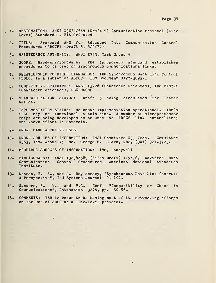
1. DESIGNATION: ANSI X3S34/589 (Draft 5) Communication Protocol (LinkLevel) Standards - Bit Oriented
2. TITLE: Proposed ANS for Advanced Data Communication ControlProcedures (ADCCP) (Draft 5, 4/9/76)
3. MAINTENANCE AUTHORITY: ANSI X353, Task Group 4
4. SCOPE: Hardware/Software. The (proposed) standard establishesprocedures to be used on synchronous communications links.
5. RELATIONSHIP TO OTHER STANDARDS: IBM Synchronous Data Link Control(SDLC) is a subset of ADCCP. IBM Document GA27-3093-1
.6. COMPETITIVE STANDARDS: ANSI X3-28 (Character oriented), IBM BISYNC(Character oriented), DEC DDCMP
7. STANDARDIZATION STATUS: Draft 5 being circulated for letterballot
.
8. IMPLEMENTATION STATUS: No known implementation operational. IBM'sSDLC may be functional a this time. A number of microprocessorchips are being developed to be used as ADCCP link controllers;one known effort is Motorola.
9 . KNOWN MANUFACTURING USES:
10 . KNOWN SOURCES OF INFORMATION: ANSI Committee X3, Tech. CommitteeX3S3, Task Group 4; Mr. George E. Clark, NBS, (301) 921-3723-
11. PROBABLE SOURCES OF INFORMATION: IBM, Honeywell
12 . BIBLIOGRAPHY: ANSI X3S34/589 (Fifth Draft) 4/9/76, Advanced DataCommunication Control Procedures, American National StandardsInstitute.
13* Donnan, R. A., and J. Ray Kersey, "Synchronous Data Link Control:A Perspective", IBM Systems Journal. 2, 197. 1
14. Sanders, R. W., and V.G. Cerf, "Compatibility or Chaos inCommunications", Datamation, 3/76, pp. 50-55-
15* COMMENTS: IBM is known to be basing most of its networking effortson the use of SDLC as a link-level protocol.
Page 36
CONCLUSION
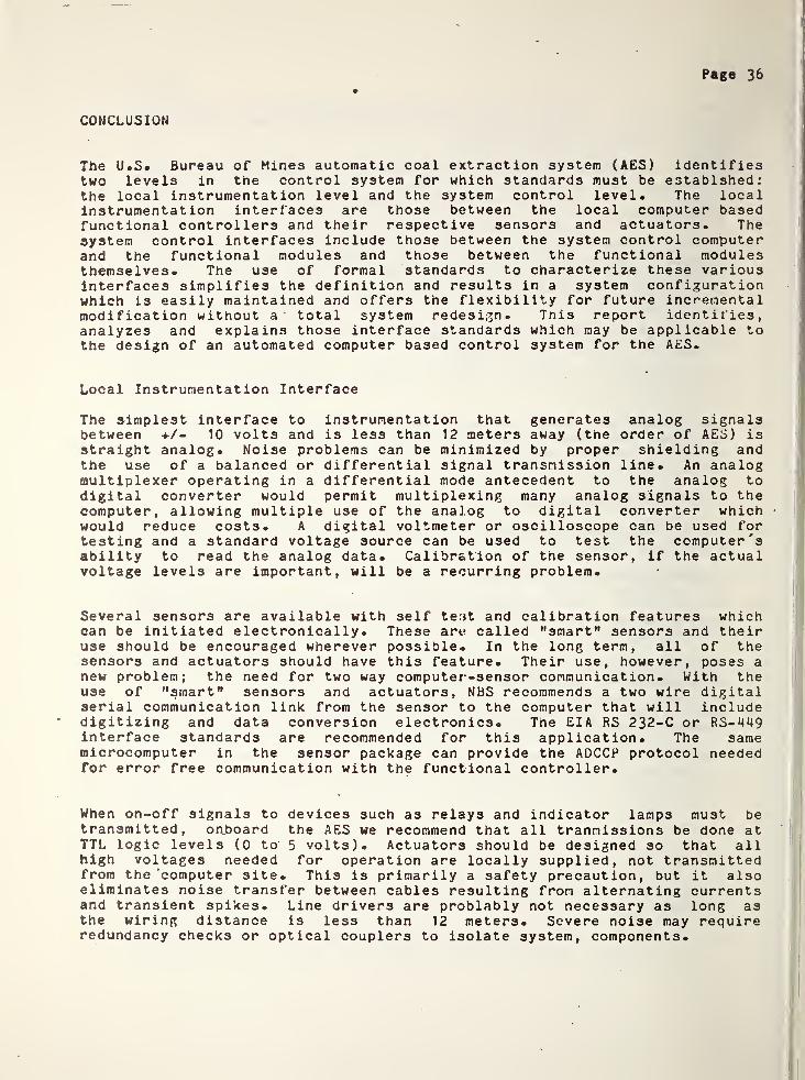
The U.S. Bureau of Mines automatic coal extraction system (AES) identifiestwo levels in the control system for which standards must be establshed:the local instrumentation level and the system control level. The localinstrumentation interlaces are those between the local computer basedfunctional controllers and their respective sensors and actuators. Thesystem control interfaces include those between the system control computerand the functional modules and those between the functional modulesthemselves. The use of formal standards to characterize these variousinterfaces simplifies the definition and results in a system configurationwhich is easily maintained and offers the flexibility for future incrementalmodification without a total system redesign. Tnis report identifies,analyzes and explains those interface standards which may be applicable tothe design of an automated computer based control system for the AES.
Local Instrumentation Interface
The simplest interface to instrumentation that generates analog signalsbetween +/- 10 volts and is less than 12 meters away (the order of AES) isstraight analog. Noise problems can be minimized by proper shielding andthe use of a balanced or differential signal transmission line. An analogmultiplexer operating in a differential mode antecedent to the analog todigital converter would permit multiplexing many analog signals to thecomputer, allowing multiple use of the analog to digital converter whichwould reduce costs. A digital voltmeter or oscilloscope can be used fortesting and a standard voltage source can be used to test the computer'sability to read the analog data. Calibration of the sensor, if the actualvoltage levels are important, will be a recurring problem.
Several sensors are available with self test and calibration features whichcan be initiated electronically. These are called "smart" sensors and theiruse should be encouraged wherever possible. In the long term, all of thesensors and actuators should have this feature. Their use, however, poses anew problem; the need for two way computer-sensor communication. With theuse of "smart" sensors and actuators, NBS recommends a two wire digitalserial communication link from the sensor to the computer that will includedigitizing and data conversion electronics. The EIA RS 232-C or RS-1J49interface standards are recommended for this application. The samemicrocomputer in the sensor package can provide the ADCCP protocol neededfor error free communication with the functional controller.
When on-off signals to devices such as relays and indicator lamps must betransmitted, onboard the AES we recommend that all trannis3ions be done atTTL logic levels (0 to' 5 volts). Actuators should be designed so that allhigh voltages needed for operation are locally supplied, not transmittedfrom the ‘computer site. This is primarily a safety precaution, but it alsoeliminates noise transfer between cables resulting from alternating currentsand transient spikes. Line drivers are problably not necessary as long asthe wiring distance is less than 12 meters. Severe noise may requireredundancy checks or optical couplers to isolate system, components.
APPENDICES
A. Statement of Work ............ 38
B. Interface StandardsTTL 3920 MA CURHENT LOOP 43RS 232-C 45RS 449 51IEEE 583 54IEEE 488 61MILSTD 1553 A 66ANSI X3-28 70ANSI ADCCP 73

I
1
Page 37
System Control Interface
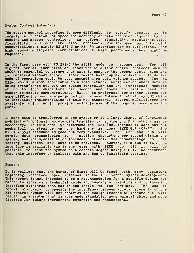
The system control Interface is more difficult to specify because it islargely a function of speed and accuracy of data transfer required by themodules and system controller. As before, simplicity, maintainability,flexibility, and cost are also important. For low speed point to pointcommunications a simple RS 232-C or RS-449 interface may be sufficient. Forhigh speed multipoint communications a high performance bus might berequired.
In the first case with RS 232-C the ASCII code is recommended. For alldigital serial communication links use of a link control protocol such asADCCP. is essential to assure that data is sent to the proper destination andis received without error. Either 2-wire half duplex or 4-wire full duplexmode of operations could be used depending on data volumes needed. The HS232-C would be most applicable to a star network configuration where data isbeing transferred between the system controller and the functional modulesat up to 1000 characters per second and there is little need formodule-to-module communications. RS-449 is preferable for higher speeds butsome difficulty may be experienced in the near future in obtaining LSI chipsto facilitate implementation of this new standard. Several multiplexers areavailable which would provide multiple use of the computer communicationport.
If more data is transferred in the system or if a large degree of functionalmodule-to-functional module data transfer is required, a Bus network may benecessary. In this case, we recommend the IEEE 488, because it does not putmechanical constraints on the hardware a3 does IEEE 583 (CAMAC). TheMILSTD-1553A standard is good but very expensive. The IEEE 488 bus willpermit data transmission at 1 million characters per second within thesystem, and its specification includes protocol. One disadvantage is thattesting equipment may have to be provided. However, if a Bus to RS 232 Cinterface is available (as is the case with IEEE 488) (2) it will bepossible to test the system to a certain degree using a CRT. We recommendthat this interface be included with any Bus to facilitate testing.
Summary
It is realized that the Bureau of Mines will be faced with many decisionsregarding interface specifications in the AES control system development.This report is not intended to be a recommendation for a specific design butrather to serve as a technical guide and summary of existing and forthcominginterface standards that may be applicable to the project. The use offormal standards to specify the interfaces between modular elements of theAES control system will not restrict the design freedom of vendors but willresult in a system that is more understandable, more maintainable, and moreflexible for future incremental expansion and enhancement.
Page 38
STATEMENT OF WORK
Objective
The Bureau of Mines is engaged in the development of a modular controlsystem for face equipment which has automated subsystems to control suchunderground mining tasks as the cutting cycle, guidance, roof support, 0 androof bolting. The National Bureau of Standards has discussed with theBureau the interface problems inherent in this modular control system.These interfaces range from the sensor-to-controller interface, which may beanalog or digital communication, to the onboard controller-to-remotesupervisory computer which is normally digital communication. This projectwill recommend the most appropriate interface standards to apply in cases asthis, which, among other benefits, will improve project management and thefinal assembly of vendor-developed subsystems.
1* To identify those current analog and digital standards relevant tosensor-based equipment.
2. To analyze those standards and determine their merit to the Bureau ofMines Project.
3« To recommend on the basis of National Bureau of Standards experience andexpertise, with the findings in 1 and 2 above, the most appropriatestandards for the sensor-to-controller interface, possible subsystemscontroller-to-systera control interface, and system controller-to-supervisorycontrol system interface.
Page 39
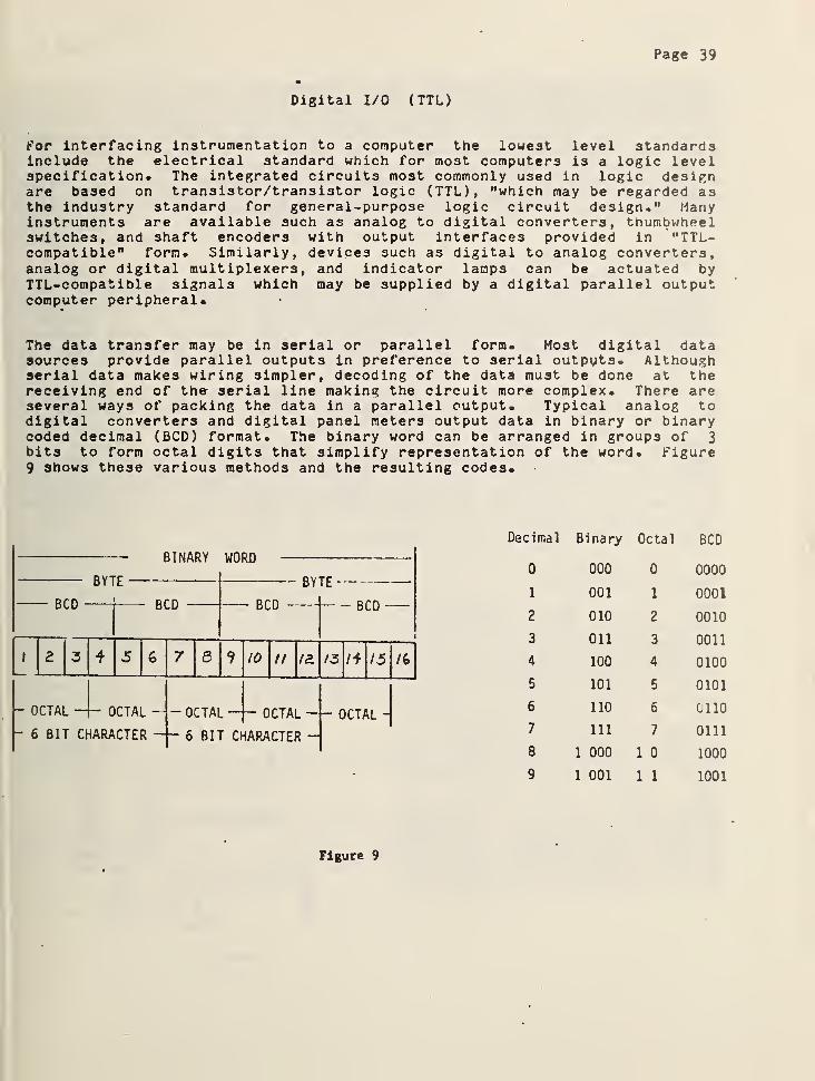
Digital I/O ( TTL)
For interfacing instrumentation to a computer the lowest level standardsinclude the electrical standard which for most computers is a logic levelspecification. The integrated circuits most commonly used in logic designare based on transistor/transistor logic (TTL), "which may be regarded asthe industry standard for general-purpose logic circuit design." Manyinstruments are available such as analog to digital converters, thumbwheelswitches, and shaft encoders with output interfaces provided in "TTL-compatible" form. Similarly, devices such as digital to analog converters,analog or digital multiplexers, and indicator lamps can be actuated byTTL-compatible signals which may be supplied by a digital parallel outputcomputer peripheral.
The data transfer may be in serial or parallel form. Most digital datasources provide parallel outputs in preference to serial outputs. Althoughserial data makes wiring simpler, decoding of the data must be done at thereceiving end of the serial line making the circuit more complex. There areseveral ways of packing the data in a parallel output. Typical analog todigital converters and digital panel meters output data in binary or binarycoded decimal (BCD) format. The binary word can be arranged in groups of 3bits to form octal digits that simplify representation of the word, figure9 shows these various methods and the resulting codes.
BINARY WORD
BYTE
BCD BCD
BYTE
BCD BCD
OCTAL —r- OCTAL —6 BIT CHARACTER
S
- OCTAL
10 II /a 13 l+\/5aOCTAL - OCTAL -
6 BIT CHARACTER
Decimal Binary Octal BCD
0 000 0 0000
1 001 1 0001
2 010 2 0010
3 011 3 0011
4 100 4 0100
5 101 5 0101
6 110 6 0110
7 111 7 0111
8 1 000 1 0 1000
9 1 001 1 1 1001
Figure 9

Page 40
Typically, the computer peripheral which interfaces to the digital paralleldevices will have as many lines available for input or output as there arebits in the computer's word length. Thus an 8-bit microcomputer would havecircuits which exchange 8 bits of data at a time and a 16 bit minicomputerwould have circuits which exchange 16 bits of data at a time. Of course, ifa device had more information than could be transferred at one time throughone circuit, more circuits could be added and the computer could handle themsequentially. This is what is usually done by an 8 bit microcomputer whichrequires data from a 12 bit analog to digital converter.
Technical Specifications
Integrated circuits of the TTL type all have bipolaruniversal application of bipolar logic, voltageinterface design are relatively standard at 0 V andvoltage may be designated as the "one” or "true"open circuit to a sensor or actuator is not mistaken
logic. Because of thelevels encountered in
+3 to +5 V. Eitherstate to assure that anfor a true condition.
The output drive capability of a TTL circuit is designated as its "fan-out."This is a number which represents the number of unit loads that the circuitcan drive. It is important to consider when the output of, say, thecomputer, will be used to drive several digital circuits. Ordinary TTLcircuits have fan-outs of between 5 and 10 with the actual fan-out usuallydefined by the manufacturer of the equipment. Of equal importance is the"fan-in" of the circuit to be driven. Thus, a logic element with a fan-outof 10 can drive normalized input logic elements with a total fan-in of 10 orless. Reliable operation is assured if the manufacturer's worst caseanalysis of the circuits being considered is. followed.
Typical Application
There are many applicationsinvolving the direct interface ofdigital instrumentation to digitalcomputers which illustrate theutility of the TTL specifications ina control environment. Figure 10depicts a method of computer controlfor a laboratory manipulatordeveloped at NBS. The computer is aDEC PDP11/45 With a DR-1 1C paralleldigital interface permitting 16lines of data input and 16 lines ofdata output. The DR-1 1C isconnected to the laboratoryequipment 35 meters away by fortyparallel wires powered by 7406 linedrivers. • The laboratory interfacehardware consists of two parts: aninput section and an output section.
Figure 10

Page Ml
Input Section - A 3ixty-four channel analog multiplexer followed by a 14 bitanalog to digital converter forms the heart of the input section* Thisaccepts analog signals in the range of -10 volts to +10 volts* Negativevoltages are converted to 2's complement form.
Output from the A/D converter is carried to the computer on the 16 datainput lines. Since the A/D converter has only a 14 bit output, the mostsignificant (sign) bit is connected to the three most significant computerinput lines. This causes the computer to read the correct values for .bothpositive and negative (2's complement) numbers.
Data transfer between the A/D converter and the computer is signaled by a
pulse' on the data transmitted line. This pulse, initiated by the computer,indicates that the data lines have been sampled. The data transmitted pulseis used both to step the analog multiplexer to the next input and toinitiate the analog to digital conversion cycle on the new input voltage.The input software is timed to sample the input data at a rate slower thanthe conversion rate of the A/D system. Thus, a "conversion completed"signal is not required by the computer, and only one control line is neededto advance the converter to the next channel.
The multiplexer is operated in a sequential mode. It is reset to channelzero by a reset pulse derived from the output section. Each datatransmitted pulse steps the multiplexer to the next sequential channel. Theinput section is thus completely under computer control.
Output Section - A sixteen channel digital demultiplexer routes outputsignals from the DR11-C to sixteen holding registers. These provide eitherdigital output directly, or are connected to digital to analog converters soas to provide analog voltages. Data transfer between the DR11-C and theoutput section is initiated by a pulse on the data present line. The datapresent pulse occurs simultaneously with the appearance of data on theDR11-C output lines. This pulse is delayed in the laboratory interfacehardware for two microseconds before actuating the digital demultiplexer soas to allow time for the data lines to settle. The delayed data presentpulse gates the output data into the selected holding register and thensteps the address counter to the next address.
The most significant (sign) bit of the output is decoded as a reset signaland is used to set the demultiplexer address counter to Channel 1 as well asto reset the analog multiplexer address in the input section.
Using the sign bit for control means that only 15 bits of output areavailable for data. The numerical range is thus restricted to 0 to 32,767.The digital to analog converters are adjusted such that numerical 0corresponds to -*-10 volts, 16,384 to zero volts, and 32,767 to -10 volts.
References
Page 42
Finkel, Jules, Computer Aided Experimentation: Interfacing to Minicomputers(John Wi *
.»/, New York) 1975
NBSIR 75-973 "Guide to Improving the Performance of a Manipulator System forNuclear Fuel Handling Through Computer Controls" John Evan3, Jr., et al.,November 1975*

Page 43
20 MA CURRENT LOOP INTERFACE
One of the most popular, though informal, standards for low speedtelecommunications is the 20 millianp current loop interface. Developedoriginally by the Teletype Corporation and now quite widely used, the datatransmission scheme has never achieved formal standardization. It isgenerally used for simple low speed applications.
The standard is usually applied to teletypewriters and other keyboardterminals such as CRT's. The transmission rates are usually low rangingfrom 10 characters/sec to 120 characters/sec since these terminals are usedfor data transactions at the man-machine interface.
Because the standard' is based on electrical current levels, it is highlyimmune to noise and is ideal for communications in high electrical noiseenvironments such as shop floors and over long distances (30 to 300 metersat 600 bps) where noise pickup might introduce errors in transmission. A
common application is the use of a 20 MA current loop where the terminal isa keyboard teletypewriter being used as a console to a computer.
Recently commercial modules have been introduced which include all of thecircuitry necessary to communicate between a current loop serial device anda digital parallel input or digital parallel output device. This hasexpanded the use of this standard to where it can be applied tocommunication systems involving analog to digital converters, analogmultiplexers, and digital to analog converters. These devices can now beused in areas where high noise often creates problems in data transmission.They can transmit at up to 1 9 . 2 kilobits p»r second.
Technical Description
The standard specifies a 20 MA current level in the circuit, which by simpleon-off operation is used to transmit the proper code (usually ASCIIcharacters). Figure 11 gives the code pattern showing the nominal currentlevels. There are times that 60 MA current levels have been used, but theseare not common.
20 KA —
0 KA
I I
I f
I *
I I
I
«
I I
! 1
CO COLT
T
Figure 11

Page 44
Figure 12
Each serial character consists of one start bit, seven ASCII-coded databits, a parity bit and two stop bits. Under quiescent conditions all loopcircuits are closed and 20 MA flows. A start bit, followed by the data bitsis transmitted by operating one of the transmitter switches. The receivingdevice detects the presence or absence of current as shown in figure 12.
Typical Application
Figure 13 illustrates an application where a teleprinter is used tointerrogate a remote digital thumbwheel switch. The current loop regulatorcan be a simple 6 volt power supply with a variable resistor to establish a
loop current of 20 MA. The two digit thumbwheel switch has 10 numbers oneach thumbwheel, 0 through 9 and has a BCD complement output whichinterfaces directly to a transmitter card that converts the parallel inputsinto a serial ASCII coded current loop bit stream. The transmitter caninterface with up to 32 digital parallel inputs. In this application thetwo digit switch requires only eight. The transmitter card is generally runas a passive device, that is, it does not supply any current to the currentloop, it acts only as a switch to interrupt the current flow as required togenerate the ASCII characters.
Convert Status
5
5
Figure 13
Page 45
* EIA RS 232-C
The standard interface between data terminal equipment (DTK) and datacommunications equipment (DCE) is Electronic Industries Association HS232-C. The standard describes a widely used form of serial, binary datainterchange. While detail is provided in reference RS 232-C, a summary oftechnological constraints and of interface functions is provided in thisAppendix. The interface standard defines electrical signal characterist ics
,
mechanical interface characteristics, functional descriptions of interfacecircuits and standard interfaces for selected communication systemsconfigurations. The standard also contains explanations and recommendationsas well as a glossary of terms. It should be noted that data must beserialized by the data terminal equipment, so that the data communicationsequipment may be independent of the character length and codes used by thedata terminal equipment. No restrictions on bit sequence arrangementsprovided by the DTE must be made by the DCE.
This discussion of HS 232-C borrows liberally from previous publications atthe National Bureau of Standards. ( see NBS Technical Note 843 )
Technical Description
The electrical interface is characterized by positive and negative voltageswings at the interface: a negative signal signifying the marking conditionand a positive signal signifying the space condition. Broad voltage limitsare specified for both positive and negative polarities (3 volts to 25volts). The region between negative 3 and positive 3 volts is defined asthe transition region, in which signals are not defined. Further details asto equivalent circuit configuration, circuit parameter tolerances and otherdetail are given in document RS 232-C.
The mechanical interface is located at a pluggable connector signalinterface point. The female connector is associated with the DTE, the malecounterpart with the DCE. An extension cable is provided with the DTE, andis optional with the DCE. The connector provides 25 circuits, and pinnunvber assignment for circuits are part of the standard. Although thestandard specifies that pin assignments listed in the standard shall beused, it also specifies that "pin assignments for circuits not specificallydefined ... are to be made by mutual agreement. Preference should be givento the use of unassigned pins, but in the event that additioal pins arerequired, extreme caution should be taken in their selection."
The functional description of the interface provides for 25 circuits. Fourare unassigned for use as spares. Of the 21 remaining, there are fourgeneral categories: Ground or common return, Data circuits, Controlcircuits, and Timing circuits. Functions assigned to the various circuitsare described below.
Two distinct ground circuits are provided. PROTECTIVE GROUND iselectrically bonded to the equipment frame. It may be further connected to
Page 46l
external grounds as required ty applicable regulations. SIGNAL GHOUUDestablishes the common ground reference potential for all interchangecircuits except for the PROTECTIVE GROUND circuit*
There are two circuits which carry data.
The TRANSMITTED DATA circuit carries data from the local DTE to the localDCE and from there to the distant communications and processing equipment.When no data are transmitted, this circuit is held in the marking or OFFcondition. Data cannot be transmitted unless all of the following circuitsare in the ON conditions (when implemented): REQUEST TO SEND, CLEAR TOSEND, DATA SET READY, DATA TERMINAL READY.
The RECEIVED DATA circuit carries data from the receiving DCE in response tothe remote DCE and DTE. This circuit is held in the OFF condition when thecircuit RECEIVED LINE SIGNAL DETECTOR is in the OFF condition.
Eight control circuits are provided in RS 232-C.
The request to send circuit is used to condition the local DCE for datatransmission. On a two way alternate channel this means control of thedirection of data transmission of the local DCE. The ON- condition maintainsthe DCE in the transmit mode, and in the case of two way alternate modeinhibits the receive mode. The OFF condition maintains the DCE in thenontransmit mode, and in the case of the two way alternate mode enables thereceive mode. The OFF-to-ON transition puts the DCE into the transmit mode,and generates the CLEAR TO SEND SIGNAL. The ON-to-OFF transition puts theDCE into the non-transmit or receive mode.
Signals on the CLEAR TO SEND circuit are generated by the DCE and indicateto the DTE that the DCE is ready to transmit data. The ON condition,together with the ON conditions on all of the circuits: REQUEST TO SEND,DATA SET READY, and DATA TERMINAL READY, (when implemented) indicate to theDTE that signals can be transmitted on the TRANSMITTED DATA circuit. TheOFF condition indicates to the DTE that it should not transmit data. The ONcondition on the CLEAR TO SEND circuit is a response to the simultaneous ONconditions on circuits DATA SET READY, and REQUEST TO SEND.
Signals on the DATA SET READY circuit indicate the status of the local DCE.The ON condition indicates that the local DCE is connected to acommunications channel (off-hook in switched service), and that the localDCE is not in test, alternate voice or dial mode, and that the local DCE hascompleted any timing functions required by the switching system. It alsoindicates that the local DCE has completed call establishment, and thetransmission of a discrete answer tone, the duration of which is controlledonly by the local data set, if these functions are implemented.
Signals on the DATA TERMINAL READY circuit go to the DCE and controlswitching of the DCE to the communications channel. The ON conditionprepares the DCE to be connected to the communications channel and maintains

Page U7
the connection established by external means, i.e. manual call origination,manual answering, or automatic call origination. The OFF condition causesthe DCE to be removed from the communications channel, following completionof any in-process transmission.
The RING INDICATOR circuit ON condition received from the DCE indicates tothe DTE that a ringing signal is being received on the communicationschannel, from the distant DCE. ON and OFF conditions correspond to the ringand no-ring signals.
The RECEIVED LINE SIGNAL DETECTOR circuit ON condition indicates that theDCE -is receiving a signal suitable for demodulation. Criteria forsuitability are established by the DCE manufacturer.
The standard includes a SIGNAL QUALITY DETECTOR circuit. An QN conditionreceived from DCE indicates to the DTE that there is no reason to believethat an error has occurred. The OFF condition indicates that there is a
high probability of error. This signal may be used to call for automaticretransmission of a previously transmitted signal.
Signals on the DATA SIGNAL RATE SELECTOR circuit originate at the DTE or DCEto select one of two signalling rates available in a dual rate synchronousDCE, or one of two ranges available in a dual range asychronous DCE. The ONcondition selects the higher rate or range. One circuit is available forthis function. The signal source may be either in the DTE or the DCE.
Three circuits provide for timing information flow between DTE and DCE.
Two of them are called TRANSMITTER SIGNAL ELEMENT TIMING. They providetiming signals, originating either from the DCE or the DTE, indicatingsignal element center, (DTE source) or signal element transitions (DCEsource) on the TRANSMITTED DATA circuit. Only one of the circuits isemployed in any particular implementation.
The other timing circuit is called the RECEIVER SIGNAL ELEMENT TIMING (DCEsource). Signals on this circuit provide received signal element timinginformation from the DCE to the DTE. The On to OFF transition on thiscircuit nominally indicates the center of each signal element on the circuitRECEIVED DATA.
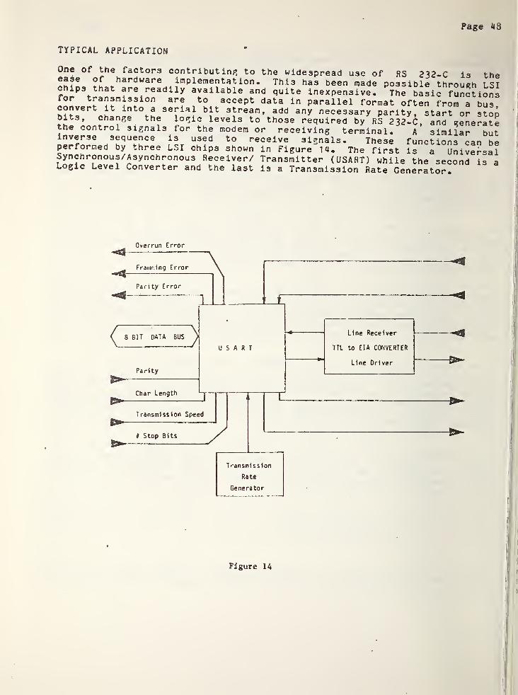
Page 48
TYPICAL APPLICATION
One of the factors contributing to the widespread use of RS 232-C is the®afe
,
hardware implementation. This has been made possible through LSIchips that are readily available and quite inexpensive. The basic functionsfor transmission are to accept data in parallel format often from a busconvert it into a serial bit stream, add any necessary parity, start or stopbits, change the logic levels to those required by RS 232-C, and generatethe control signals for the modem or receiving terminal. A similar butinverse sequence is used to receive signals. These functions can beperformed by three LSI chips shown in Figure 14. The first is a UniversalSynchronous/Asynchronous Receiver/ Transmitter (USART) while the second is aLogic Level Converter and the last is a Transmission Rate Generator.
Overrun Error
Figure 14

Page *49
Although the standard specifies gt maximum line length of 12 meters, the ICline drivers • commonly available allow better performance. Some commercialdata terminal equipment at NBS operates reliably up to 1000 meters at 2*100
bits per second over four wire unshielded cable. Thi3 feature has allowedthe increasing use of remote terminals without modems. An example of thissimplified use of RS 232-C is given in Figure 15 detailing configurationused by NBS its Experimental Computer Facility to support a number of CRTand teleprinter terminals. Four wire unshielded cable is used. RS 232-Ccircuits in operation are:
TRANSMITTED DATA Pin 2RECEIVED DATA Pin 3SIGNAL GROUND Pin 7CLEAR TO SEND Pin 5DATA SET READY Pin 6
RECEIVED LINE SIGNAL DETECTOR.
Pin 8
Figure 15
The first three are obvious for bidirectional communication and require noexplanation. Their functions occupy three of the four wires in the cable.The remaining three functions represent control signals directed to the dataterminal equipment. RS 232-C specifies that a DTE shall not transmit unlessall three of these circuits are in the ON condition. These three circuitsare all energized by the fourth wire in the cable which is jumpered to pins5, 6 and 8 at the RS 232-C connector of the data terminal. At the computerend of the cable this wire is maintained in the ON condition by a powersupply. Thus the ON condition is seen by the data terminal equipmentcontinuously on all three function pins.
Page 50
Conclusions
Standardization of the DTE - DCE interface is of importance to thedevelopment of reliable, efficient and cost effective computercommunications systems. Despite the fact that standards have been developedin the commercial sector, many problems still remain. As an example KS232-C is not specified to operate over more than 12 meters of cable betweenDTE and DCE, as a result of the high driver impedance. Also the highimpedance of both driver and receiver makes the circuit susceptible topick-up of extraneous signals. The high voltages generate cross-talk inadjacent circuits, make shielding difficult, and create possible securityproblems. for these reasons KS 232-C has not been adopted by the AmericanNational Standards Institute.
The existence of standard interface specifications does not insureplug-to-plug interoperabi 1 ity of devices in all cases. Products of manydata communications and computer peripheral manufacturers requirespecifically engineered interfaces. Often interface requirements vary frommanufacturer to manufacturer, and vary often within one product- line. EIAstandards were originally designed around the Bell System 102 data set.Today this modem represents only a small part of the total interfaceequipment universe. Expanding requirements have added additional functionsbeyond those specified in the standards. Careful analysis of requirementsin each individual DCE application is required, applicability of existingstandards must be determined, additional requirements must be specified, andinterface engineering efforts are required to provide needed capabilities*Alternatively, consideration can be given to newly developing DTE-DCEinterface standards which are discussed under RS-^Q.

Page 51
RS 449
A new generation of interface standards ha3 evolved to replace the wellknown and widely used RS 232-C which is limited by its inability to handlelong cable runs and truly high data rates- These new standards include thecommon data terminal equipment to data communication equipment (DTE-DCE)interface for data transmission over analog telecommunication networks- aswell as direct DTE-DTE operation.
The first in the new series of data communications interface standards to becompleted and approved are the general-purpose electrical characteristicsfor digital interface circuits. They are EIA Recommended Standards RS-422for balanced circuits and RS-423 for unbalanced circuits. As such both formcomponent parts of the RS-449 specification. The new standards weredeveloped to meet the advancing state-of-the-art in integrated circuittechnology and greatly enhance the performance, as compared to RS 232-C, ofd.c. digital baseband signals across interfaces. It was necessary todevelop two general-purpose standards, one for balanced and another forunbalanced electrical characteristics to provide a wide range of flexibilityfor user applications.
The balanced electrical characteristics of RS-422 are designed forapplications using typical twisted-pair telephone cable. High qualitysignals can be provided over cable distances up to 1200 meters at datasignalling rates up to 100 kbit/s while higher data signalling rates, up to10 mbit/s, can be employed for cable distances progressively decreasing to12 meters.
These operating distances, as specified in Section 7 of RS-422, were set asconservative guidelines to ensure reliable performance in a wide range ofuser environments. With additional consideration given to the specificapplication, however, greatly increased operating distances can be realized.While keeping within the environmental constraints specified in Section 5 ofRS-422, the cable length becomes a function of the cable parameters, cabletermination, and amount of signal distortion (jitter) that can be tolerated.It has been shown empirically that cable distances of several kilometers arepossible for lower data signalling rates.
The greatly improved performance now available from the balanced electricalcharacteristics opens the way for a number of applications where dataterminal equipment (DTE) can be directly connected via twisted pair cable toa central computer, concentrator or other DTE's within a large facility. Asa result, the requirement and expense is eliminated for data communicatingequipment ' (DCE), such as modems or data sets, for such "in-house"applications.
Page 52
•
The unbalanced electrical characteristics of RS-423 are designed to providesuperior performance to those of RS 232-C. A low impedance single-endedgenerator is specified with a differential receiver having a transitionthreshold of 200mV. Operation over cable distances up to 1200 meters atdata signalling rates up to 3 kbit/s provide good quality signals whilekeeping near-end crosstalk within 1 volt peak. Likewise, higher datasignalling rates up to 300 kbit/s can also be employed for cable distancesprogressively decreasing to 12 meters. The primary limitation of operatingdistance with unbalanced circuits is near-end crosstalk, rather than signalquality as with the balanced circuits. In comparison, the performance o.f HS232-C is generally limited to cable distances of 15 meters at datasignalling rates up to 20 kbit/s.
The most significant feature built into RS-423 is its capability tointeroperate with both HS 232-C circuits and RS-422 circuits. This providesthe key mechanism for an orderly transition from RS 232-C to the newgeneration of interface standards. The approach taken was to place the onusfor interoperability on the equipment implementing RS-423* -so that noretrofitting will be required for existing RS 232-C equipment. However,when interoperating with RS 232-C equipment, performance is limited to thatassociated with RS 232-C.
The unbalanced electrical characteristics allow a user to gracefully phaseexisting equipment out of use while bringing in a new generation ofequipment to meet advancing requirements. At the same time, a signficantimprovement in operating performance can be realized as the RS 232-Cequipment phases out. As a separate stand-alone standards, RS-423 can bereferenced for application by specific interface standards, as discussedlater, as well as specified for any special purpose user application.
The DTE-DCE interface for applications involving modems has traditionallyrequired the use of a number of parallel control circuits for operation ofthe modem. These are necessary for such functions as changing direction oftransmission in half duplex operation over 2-wire circuits, modemsynchronization and conrol of fault isolation loopback: .
EIA RS-449 provides the complete transition mechanism with the objective ofevolving to the future mechanism with the with the objective of evolving tothe future generation of equipment. RS-449 has been primarily designed, asRS 232-C, for user applications which allows equipment of one manufactureron one side of the interface to be directly connected to equipment ofanother manufacturer on the other side of the interface without additionaltechnical considerations.
One of the more notable improvements of RS-449 over RS 232-C is the use ofthe new unbalanced electrical characteristics of RS-423. Not only does thisprovide significantly improved performance between RS-449 equipment, butfacilitates interoperability with RS 232-C. The full potential performanceof RS-423* however, has not been used to full advantage by RS-449 because ofthe requirement for compatibility with RS 232-C. Consequential designdecisions limit the RS-449 equipment to data signalling rates of 60 kbit/s

Page 53
and cable distances of 61 meters. This is still a significant improvementover RS 232-C which is limited to 20 kbit/s and 12 meters.
The second step in interface evolution is the provision for use of thebalanced RS-422 electrical characteristics on the interchange circuits thatmay switch at the operating data signalling rate. These include data,timing, and selected control circuits. The option of being able toimplement either the R3-423 or the RS-422 electrical characteristics onthese circuits provides for full plug compatibility.
When the balanced RS-422 option if applied, operating into the Mbit/s rangecan be employed. As a result of the much wider range of operatingcharacteristics that are possible, the necessity for additional technicalconsiderations outside the scope of the standard to tailor specificapplications is greatly reduced. The improved operation performance alsomakes DTE to DTE operation economicaly practical. Accordingly RS-449 alsowill include suitable direct connection configurations without intermediateDCE's which is an ideal configuration for use with the AES control system.
In summary, RS-449 offers considerable flexibility as well as signficantlyimproved performance to the user. When a transition must be made fromexisting RS 232-C equipment, the user would use RS-449 equipmentimplementing RS-423 unbalanced electrical characteristics on all circuits.The old equipment can then gradually phase out of use. Where a transitionis not required, the user would implement RS-449 with the RS-422 balancedelectrical characteristics on the selected circuits. This would providesuperior performance and additional flexibility in the AES application.
Page 54
IEEE 583 (CAMAC)
In 1975 the Institute of Electrical and Electronic Engineers (IEEE)published basic specifications for Computer Automated Measurement andControl (CAMAC). These specifications describe a complete modularinstrunentation/interface system with all of the mechanical, electrical, andsignal characteristics, as well as the protocol, fully defined to assureinterchangeability and compatibility. Developed originally in the nuclearfield, CAMAC has spread into a wide variety of industrial, laboratory 3ndmedical applications. CAMAC is a high speed instrumentation and interfacesystem in which modular functional units connect to a standardized datahighway (Dataway) for transmission of digital informtion. It is the onlywidely used nonproprietary interface system based on interchangeablestandardized plug-in nodules. Figure 16 gives a brief overview of a CAI1ACsystem showing the various interfaces.
The modules, which are interchangeable regardless of source, plug into a
standardized enclosure (crate) that includes the Datway along which the dataand control information are carried. The Dataway is a parallel bus that canhandle data words of up to 24 bits. Minimum Dataway cycle time is onemicrosecond. Each crate can accommodate up to 23 modules plus a cratecontroller. Since the modules are addressed by dedicated lines from thecrate controller, they can be addressed individually or in multiple, in anycorabintaion. There are 16 subaddresses and 32 functions, binary coded.Thus the addressing capability is very high. Multiple crate systems canutilize a defined standardized parallel highway that can accommodate up to 7crates per branch, a defined standardized serial highway that canaccommodate up to 62 crates, or other types of highways, as may be desired.The system also has interrupt capabilities with demands lines from themodules to the crate controller.
Control applications where long distances are involved use serial highwaysto economize on cabling costs. The standardized CAMAC serial highway, whichcan be either bit serial or byte serial (8 bits per byte), has a maximumspped of up to 5 MHz though this drops as the number of crates and the linelength is increased.
The basic CAMAC specifications, the CAMAC parallel and serial highways, andCAMAC block transfer conventions, are all IEEE standards as listed below.They are also international standards (adopted or in process) of theInternational Electrotechnical Commission.
1. Basic CAMAC Specs IEEE Std 583-1975 IEC 516
2. CAMAC Serial Highway IEEE Std 595-1976 In process at IEC
3.'
CAMAC Parallel Highway IEEE Std 596-1976 IEC 552
4. CAMAC Block Transfer IEEE Std 683-1976 In process at IEC

These sensors or actuator devices
Go to these modules which are
interchangeable standard plug-ins
per IEEE 583
Which go to this Dataway which
Is a standardized interface orhighway with standard signals
and protocol per IEEE 583
And the Dataway connects
also to this controller,
which may be self-contained.
or which may go to a computeror other external controller.
Thus the Dataway and
the module/Dataway interface
speak a standardized language,
while this interface is
specific to the sensoror actuator device
and the rest of the moduleIs a "black box" with no
design constraints.
This highway may be a
standardized serial highway (IEEE 595), or a
standardized parallel highway (IEEE 596), or a
non-standard highway.
Figure 16
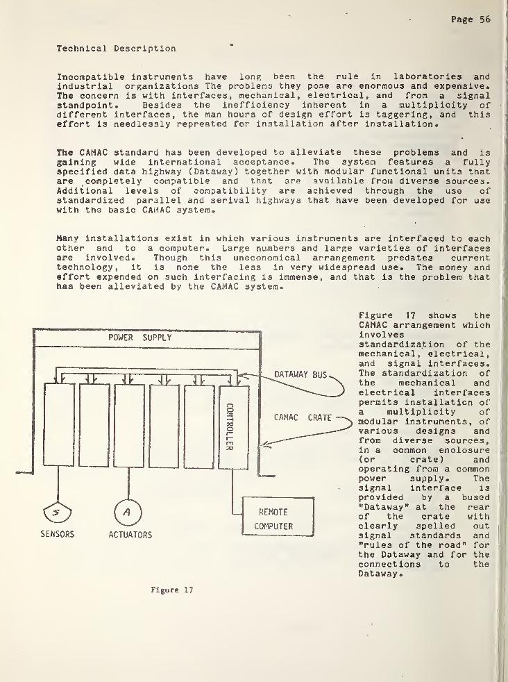
Page 56
Technical Description
Incompatible instruments have long been the rule in laboratories andindustrial organizations The problems they pose are enormous and expensive*The concern is with interfaces, mechanical, electrical, and from a signalstandpoint* Besides the inefficiency inherent in a multiplicity ofdifferent interfaces, the man hours of design effort is taggering, and thiseffort is needlessly repreated for installation after installation*
The CAMAC standard has been developed to alleviate these problems and isgaining wide international acceptance. The system features a fullyspecified data highway (Dataway) together with modular functional units thatare completely compatible and that are available from diverse sources.Additional levels of compatibility are achieved through the use ofstandardized parallel and serival highways that have been developed for usewith the basic CAMAC system*
Many installations exist in which various instruments are interfaced to eachother and to a computer. Large numbers and large varieties of interfacesare involved* Though this uneconomical arrangement predates currenttechnology, it is none the less in very widespread use. The money andeffort expended on such interfacing is immense, and that is the problem thathas been alleviated by the CAMAC system.
Figure 17 shows theCAMAC arrangement whichinvolvesstandardization of themechanical, electrical,and signal interfaces.The standardization ofthe mechanical andelectrical interfacespermits installation ofa multiplicity ofmodular instruments, ofvarious designs andfrom diverse sources,in a common enclosure(or crate) andoperating from a commonpower supply. Thesignal interface isprovided by a bused"Dataway" at the rearof the crate withclearly spelled outsignal standards and"rules of the road" forthe Dataway and for theconnections to theDataway.
Figure 17
Page 57
The figure also shows how sensors, actuators and peripherals communicatewith the computer via CAMAC modules through the common Dataway and a singleinterface.
The system has a 1 microsecond Dataway cycle time and a very highaddressing capability. The Dataway is parallel, with 24 read lines and 24write lines, so that words of 24 bits or less can be handled in a singledata transfer. Typically, up to 23 stations can be addressed within a
crate, either singly or in any combination, with 16 subaddresses for * eachstation together with 32 function codes. This high addressing capabilityis further multiplied by 7 in the case of the standard 7 crate parallelhighway system and by 62 in the case of the standard serial highway system,both of which are discussed later.
CAMAC instruments are modular functional units that are accommodated in a
CAMAC crate. A typical CAMAC module is based on the standard 222 mm highpanel and has a basic single width of 17 mm • The modules carl come in anymultiple of this basic single width. The specifications allow completeflexibility with regard to the internal design of the modular instruments.The instrument is treated as a "black box" with the standardizationconfined to the external mechanical configuration, the electrical powerrequirements, and the signal inputs and outputs. This permits instrumentcompatibility and interchangeability without restricting the internalfunctioning of the instruments or the design details.
The CAMAC crate serves as the common housing for CAMAC instruments and alsoprovides the Dataway for all the instruments that are inserted in thecrate. The instruments receive digital inputs from and transmit theirdigital outputs along the Dataway.
All stations into which the modular instruments can be inserted areidentical except for the control station which is located at the extremeright. This station is reserved for the crate controller which handles allcommunications between the instruments and the Dataway and also between thecrates and the computer or other external controller.
A typical CAMAC crate can accommodate up to 25 single-width modules (thougha minimum of two of these are required for the crate controller), or a
lesser number of wider modules. Single width modules and modules of anymultiple width can be inserted in any combination.
The Dataway at the rear of a CAMAC crate consists primarily of bused linesthat interconnect the stations and that are utilized to transmit read,write, controls and addressing information. The Dataway includes alsopower supply buses as well as a limited number of dedicated lines. Thecontroller addresses specific stations, singly or in any combination, bymeans of dedicated station lines. A second set of dedicated lines is usedby the instruments to alert the controller when they want attention. Thisinterrupt capability is an important feature of CAMAC that has proved to beof immense value. The Dataway consists of both buses and deciated lines.
Page 58
In a 25 station crate, 24 are designated "normal" stations and are wiredidentically. The wiring of the control station is different from that ofthe normal stations. Since a crate controller must hav access to the ReadR and Write W bus lines, it must occupy at least one normal station inaddition to the control station®
1
The Dataway lines fall into four categories as follows:
1. All Station Bus Lines linking corresponding Dataway connector contactsat all stations, including the control station.
2® Normal Station Bus Lines linking correspond ing Dataway connectorcontacts at all normal stations, but not connected to the controlstation. (These include the Read and Write lines.)
3® Individual Lines between the control station and each normal station.There are two such lines for each normal station:
1. the N line (Station Number line) by which the control stationaddresses specific normal station, and
2® the L line (Look-At-Me line) which is a demand line used by thestation to advise the control station that it wishes attention.
4® Patch Contacts (for each station) that are not connected to the Datawayand are available for patch connections.
CAMAC systems vary from simple single -crate systems to complex andextensive systems with a vast number of crates distributed over aconsiderable area. The instruments withir the crate all speak a commonlanguage to the Dataway. The controller, while also speaking the commonDataway language, serves as a translator if the crate is connected to acomputer. The controller is then the one unit in the crate that must beable to communicate directly with the computer. Controllers of this sort,dedicated to specific computers, have been produced for a number ofcomputers.
In many instances, it is advantageous to make even the crate controllercomputer independent. This is done by interposing a branch driver betweenthe crate controller and the computer. The crate controller then speaksthe Dataway language and a standardized highway language. The BranchDriver also speaks the highway language, but it assumes the role ofdedicated translator, and must speak also the computer language. A singlebranch driver, capable of serving a multiplicity of crates, now becomes theone computer dependent device in the installation®
The interconnection between crates and between the crates and a computer orother controller is called the Highway. With dedicated crate controllers

Page 59
designed to interface with specific computers, the Highway becomes anextension of the computer I/O bus. Where branch drivers are used, thatportion of the Highway that interconnects the crates and branch driver canbe computer independent. Such highways can be either parallel or serial,single-ended or balanced.
Parallel highways are inherently capable of the highest data transfer rateand have maximum transparency to the Dataway. They are especiallyattractive where the highway length is not excessive so that a single-endedhighway can be used [see A2.1 . of IEEE Std 596-1976, Parallel HighwayInterface System (CAMAC)]. Parallel highways of greater length arefeasible but this requires a balanced transmission mode, using eitherbalanced transmitters and receivers or ba lanced-to-single-ended converters.Such converters permit use of single ended operation at the crates withbalanced transmission over long-span portions of the highway. Thestandardized CAMAC parallel highway of IEEE Std 596-1976 using branchdrivers and well defined crate controllers is in widespread use. The cratecontrollers are available from a number of sources, and branch drivers areavailable for a wide variety of computers.
Serial highways using a limited number of lines are particularly attractivefor installations where very long highways are required and where thehighway wiring cost can be cnsiderable significance. The standardizedCAMAC Serial System of IEEE Std 595 is capable of handling up to 62 CAMACcrates. This serial system can be either bit serial or byte serial with 8
bits per byte.
The serial highway is interfaced to the computer through a serial driveror, where an unsophisticated interface of limited capability is acceptable,through an adaptor to the teletypewriter port of the computer. The highwayis organized in a loop that begins at the defined output port of the serialdriver, goes through a serial crate controller in each CAMAC crate, andthen returns to the defined input port of the serial driver. The serialdriver communicates with the computer through a port that is specific tothe computer.
The capability of CAMAC systems can be further enhanced by the use ofmicroprocessors within the modules. This permits "local" processing andthus reduces the load on the Dataway. Alternatively, the conventionalcrate controller ca be replaced or supplemented by microprocessor-typecontrollers that can reduce the load on the computer or even eliminate theneed for a computer.
Non-CAMAC devices can be connected into CAMAC systems either in the highwayor via the Dataway by means of an interfacing module. The measuringinstrument interface bus of IEEE Std ^88-1975, Digital Interface forProgrammable Instrumentation and Related System Components (ANSIMCI. 1-1975), can be connected to the CAMAC Dataway of IEEE Std 583-1975, bymeans of a simple interface module.
Page 60
for added processing capability, the interface module can be of themicroprocessor type such as has been designed and operated at the LosAlamos Scientific Laboratory. Various console control devices (encoders,keyboards, displays, etc) that use the IEEE Std 488-1975, digital interfacebus are connected into a CAMAC system by means of this "intelligent”interface module.
CAMAC is a user-developed system which permits the configuration ofinstallations that can be easily upgraded with time and which can be madepractically independent of the control computer except for small sectionsof hardware and software. Updating of installations, such as industrialcontrol systems, has traditionally been very difficult. Since thesedifficulties are not present in CAMAC systems with standardized multisourcefunctional units, economical modernizing of CAMAC industrial controlsystems is feasible.
References
The four IEEE CAMAC standards have been compiled into a hard cover bookpublished by IEEE and distributed in cooperation with John Wiley and Sons.This volume is identified as IEEE SH06437, Library of Congress Catalog No.76-39660.
ERDA Report TID-266 18 (October 1976) is a compilation of tutorial articlesdescribing CAMAC. A great deal of information has also appeared in theliterature. The ERDA report pages 7 and 3 contain an excellent referencelist of articles and papers.
Mining applications would have a great deal in common with industrialcontrol applications in harsh environments and therefore existing CAMACindustrial installations should be studied*
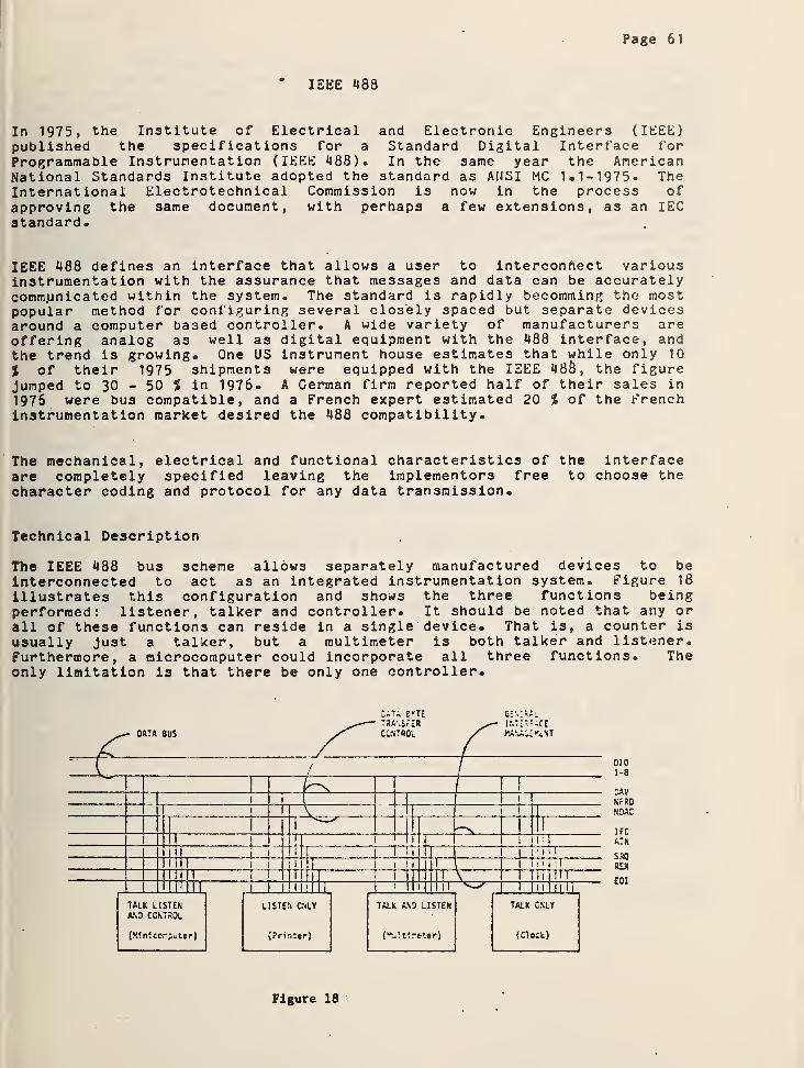
Page 61
* IEEE 480
In 1975, the Institute of Electrical and Electronic Engineers (IEEE)published the specifications for a Standard Digital Interface forProgrammable Instrumentation (IEEE 488). In the same year the AmericanNational Standards Institute adopted the standard as A1JSI MC 1.1-1975. TheInternational Electrotechnical Commission is now in the process ofapproving the same document, with perhaps a few extensions, as an IECstandard.
IEEE 488 defines an interface that allows a user to interconnect variousinstrumentation with the assurance that messages and data can be accuratelycommunicated within the system. The standard is rapidly becomming the mostpopular method for configuring several closely spaced but separate devicesaround a computer based controller. A wide variety of manufacturers areoffering analog as well as digital equipment with the 488 interface, andthe trend is growing. One US instrument house estimates that while only 10
% of their 1975 shipments were equipped with the IEEE 480, the figureJumped to 30 - 50 % in 1976. A German firm reported half of their sales in
1976 were bus compatible, and a French expert estimated 20 % of the Frenchinstrumentation market desired the 488 compatibility.
The mechanical, electrical and functional characteristics of the interfaceare completely specified leaving the implementors free to choose thecharacter coding and protocol for any data transmission.
Technical Description
The IEEE 488 bus scheme allows separately manufactured devices to beinterconnected to act as an integrated instrumentation system. Figure 18
illustrates this configuration and shows the three functions beingperformed: listener, talker and controller. It should be noted that any orall of these functions can reside in a single device. That is, a counter isusually Ju3t a talker, but a multimeter is both talker and listener.Furthermore, a microcomputer could incorporate all three functions. Theonly limitation is that there be only one controller.
6 v T£ G
0101-8
DAVNr RD
NDAC
1FCATN
SRQR£N
eoi
Figure 18

Page 62
As many as 14 devices can listen and receive data at any one time. The buscontrol lines will insure that even the solwest of the devices will beserviced without loss of data. Thus the standard appears to offer manyadvantages to a user wanting to piece together a variety of stand alonedevices from different manufacturers into a specific instrumentation systemwithout a great deal of special engineering.
The data bus which connects these components is comprised of sixteen signallines. The physical bus itself is a length of cable with the standardized,stackable connectors at each end. The standard allows 2 meters of ‘cableper instrument or 20 meters total. In this respect IEEE 488 differs fromother parallel bus schemes which involve backplane wiring in a singlechassis. No power leads are carried in the 488 bus. Each interconnectedins-trument supplies its own power.
Of the 16 lines comprising the bus 8 are used for bidirectional datatran? n'.ssion, 3 for the control of the data lines and 5 for generalinterface management.
A data bus of eight interface signal lines carries all 7 bit data.
(1) DI01 (data input output 1)
(2) DI02 (data input output 2)(3)
(8) DIQ8 (data input output 8)
Data are carried on the DIO signal lines in a bit-parallel byte-serialform, asynchronously, and generally in a bidirectional manner."
A set of three interface signal lines is used to effect the transfer ofeach byte of data on the DIO signal lines from an addressed talker to alladdressed listeners:
1. DAV(data valid) is used to indicate the condition (availability andvalidity) of information on the DIO signal lines.
2. NRFD (not ready for data) is used to indicate the condition ofreadiness of device(s) to accept data.
3. NDAC (no data accepted) is used to indicate the condition of acceptanceof data by device(s).
The DAV, NRFD, and NDAC signal lines operate in what is called a three-wire(interlocked) handshake process to transfer each data byte across theinterface.
Five interface signal lines are used to manage an orderly flow ofinformation across the interface:

Page 63
1. ATN (attention) is U3ed to specify how data on the DIO signal lines areto be interpreted and which devices must respond to the data.
2. IFC (interface clear) is used to place the interface system in a knownquiescent state.
3» SRQ (service request) is used by a device to indicate the need forattention and to request an interruption of the current sequence ofevents.
4. REN (remote enable) is used in conjunction with other messages to• select between two alternate sources of device programming data.
5« EOI (end or identify) is used to indicate the end of a multiple bytetransfer sequence or, in conjunction with ATN, to execute a pollingsequence.
For data to be transmitted over the bus it is necessary for the controllerto designate the talker from which the data is to come and the listner orlistners where the data is to go. The DIO lines carry all the data whilethe other 8 lines control the flow and interpretation of that data. Thedata can be actual measurement data, program data, addresses or commands.The type of data is indicated by the ATN line. With ATN true the data iseither addresses or commands and all devices are expected to pay attention;with ATN false the data represents measurement or program data beingtransferred between a previsouly addressed talker and listner.
The actual transfer of a single data byte on the DIO lines is controlled bythe DAV, NRFD and NDAC lines. DAV is sent by the talker to all listeners toindicate that the data is ready for transfer. NRFD is used by listeners toindicate their readiness to accept data, and NDAC signals that the listenerhas accepted the data. A typical transfer starts with DAV high. On seeingthis all listeners set NRFD low showing they are not yet ready to receiveand NDAC low showing they have not accepted the data. Seeing both signalslow the talker puts the data onto the DIO lines. When NRFD goes highindicating all listeners are ready, the talker sets DAV low to initiate thedata transfer. Each listener sets NRFD low and begins to accept the data.When completed it sets NDAC high. Sine the line is wire-ored, it will notgo high until all listeners have accepted the data. When NDAC does go high,the talker knows everyone has received the data. Talker then sets DAV highand clears the DIO lines placing the system back into its initial state.Thus the system is asynchronous and device speed independent, accommodatingboth the fastest and the slowest of listeners and talkers.

Page 64
Typical Application
The configuration in Figure 19 has been designed to select a specific analogchannel, digitize the signal, process the data, and print the result.Additionally, the system sounds an alarm if any data exceeds a specifiedlimit. One complete cycle would involve the following exchange:
1® Controller sends the listen address to the analog multiplexer followedby the channel address to be digitized and the unlisten command.
2® Controller sends the listen address to the A/D converter followed bythe program code required to initiate a measurement and the unlistencommand.
3® Controller addresses itself to listen then sends the talk address tothe A/D converter thus initiating the data transfer.
4® Controller receives the data, processes it and sends the unlistencommand.
5® If data are within proper range, the controller addresses the printerto listen and the controller to talk®
6® If any data are over range, the controller addresses the alarm tolisten and itself to talk® It then sends the proper program code tothe alarm to indicate the data are out of range. »
Figure 19
Page 65
Conclusions
IEEE 488 describes a bus scheme for interfacing a variety of separateinstruments into an integrated system without special engineering. It iswidely used and readily available from numerous suppliers. The popularityof IEEE 488 appears to be increasing. To summarize, the standard applies tosystems in which:
1. 'Only digital data is to be exchanged across the bus.
2* As few as two and up to fifteen devices are to be connected.
3* Maximum length of the bus is 20 meters.
4. Maximum data rate across the bus is one million bits per second.
Some users report that the maximum data rate across the bus is too low forsome applications. Others find difficulty in that the standard does notspecify the character code to be used for data bytes. This has led todifferent manufacturers adopting their own (ASCII, BCD, etc) thus causingproblems for users of that equipment.
An additional area of concern is that the extra cost for providing aninstrument with the optional interface to 488. One manufacturer hasestimated that the standard adds from $'0 to $900 to the cost of aninstrument depending on the range of functions needed. This cost willdecrease as special LSI chips are develoed. One chip acting as a
receiver-transmitter is already available to interface with the buselectrically but provides none of the logic functions needed.
Dispite these potential problems IEEE 488 is finding much use as a solutionto many common problems of instrumentation systems.
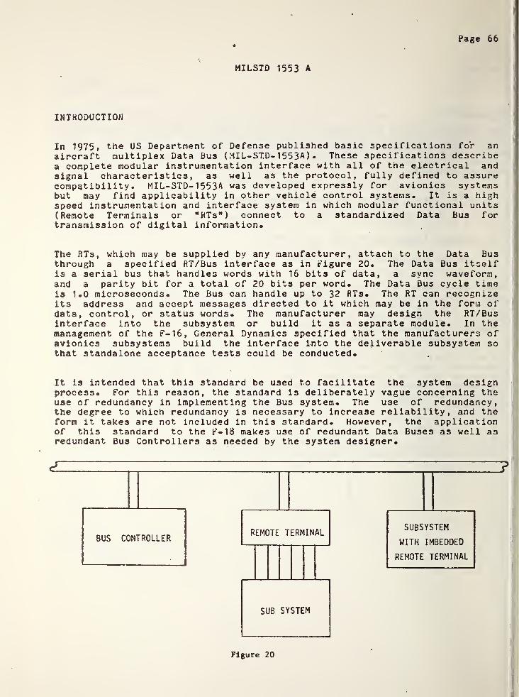
Page 66
MILSTD 1553 A
INTRODUCTION
In 1975, the US Department of Defense published basic specifications for anaircraft multiplex Data Bus (MIL-ST.D- 1 55 3 A ) . These specifications describea complete modular instrumentation interface with all of the electrical andsignal characteristics, as well as the protocol, fully defined to assurecompatibility. MIL-STD- 1 5 5 3 A was developed expressly for avionics systemsbut may find applicability in other vehicle control systems. It is a highspeed instrumentation and interface system in which modular functional units(Remote Terminals or "HTs") connect to a standardized Data Bus fortransmission of digital information.
The RTs, which may be supplied by any manufacturer, attach to the Data Busthrough a specified RT/Bus interface as in Figure 20. The Data Bus itselfis a serial bus that handles words with 16 bits of data, a sync waveform,and a parity bit for a total of 20 bits per word. The Data Bus cycle timeis 1.0 microseconds. The Bus can handle up to 32 RTs. The RT can recognizeits address and accept messages directed to it which may be in the form ofdata, control, or status words. The manufacturer may design the RT/Businterface into the subsystem or build it as a separate module. In themanagement of the r — 16, General Dynamics specified that the manufacturers ofavionics subsystems build the interface into the deliverable subsystem sothat standalone acceptance tests could be conducted.
I
It is intended that this standard be used to facilitate the system designprocess. For this reason, the standard is deliberately vague concerning theuse of redundancy in implementing the Bus system. The use of redundancy,the degree to which redundancy is necessary to increase reliability, and theform it takes are not included in this standard. However, the applicationof this standard to the F-18 makes use of redundant Data Buses as well asredundant Bus Controllers as needed by the system designer.
Figure 20
Page 67
*
At the present time this standard is being applied to the F-16, F-18 and theArmy Advanced Armed Helicopter. All of these avionics systems have beencustom built by avionics manufacturers who are interested in providing thecomplete system as a package. For this reason, it is an expensive system toinstall at the present time. The Air Force is funding an effort to build RTinterfaces using LSI technology to reduce costs, but no product is expecteduntil 1 97 9
•
Technical Description
This bus is designed to operate in a command/response mode so that the Buscontroller initiates all message transfers. Three types of messagetransfers are possible: controller to RT, RT to controller, and RT to RT.Even though this Bus could be called a "distributed communication network"since it permits RT to RT transfers, full hierarchical control of the systemis maintained by the Bus controller. For example, in the controller to RTtransfer, the controller sends a "receive" command followed by the specifiednumber of data words. The RT, after validating the message, transmits a
status word back to the controller. In an RT to controller transfer, thecontroller issues a "transmit" command to the RT, and the RT responds byreturning a status word and the specified number of data words. Lastly, inan RT to RT transfer, the controller issues a receive command to RTA,followed by a transmit command RTB. Upon completion, RTB returns a statusword back to the controller.
The transmission facility is a two conductor, twisted shielded cable with a
characteristic impedance of 70 ohms. The cable length of the. main Bus maybe up to 9 2 meters.
The remote terminal (RT) is the unit that electronically interface the Buswith the subsystems and the subsystems with the Bus. It may be a separateunit to which the subsystem interfaces, or may be imbedded in the subsystem.A redundant bus controller, when not functioning as a controller*, mayoperate as a remote terminal.
The Bus controller is a key part of the Data Bus system. It is responsiblefor sending Data Bus commands, participating in data transfer, receivingstatus responses, and monitoring system status. It is assumed that most ofthe routine minute details of bus monitoring (e.g. parity checking,terminal non-response checkout, etc.) will be accomplished by hardware,while the algorithms for bus control and decus bus control and decisionmaking will reside in software. The controller can be either a standalonecomputer dedicated to bus management or a peripheral I/O controlled on anexisting central computer.
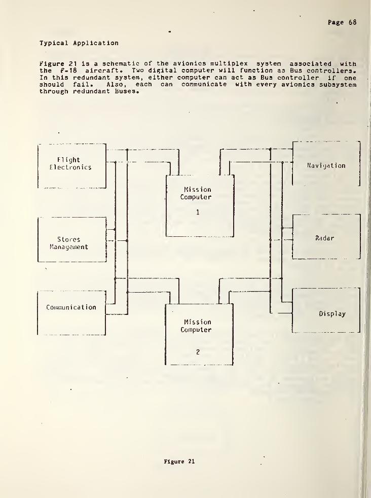
Page 68
Typical Application
Figure 21 is a schematic of the avionics multiplex system associated withthe F-18 aircraft. Two digital computer will function as Bus controllers.In this redundant system, either computer can act as Bus controller if oneshould fail. Also, each can communicate with every avionics subsystemthrough redundant Buses.
FlightElectronics
MissionComputer
StoresManagement
Communication1 1
MissionComputer
2
Radar
Displ ay
Figure 21

Page 69
References
1* MIL-STD-1553A "Aircraft Internal Time Division Command/ResponseMultiplex Data Bus," 30 April, 1975-
2- "Avionics: Military Moves to Multiplex for Aircraft," AviationWeek and Space Technology, Nov. 29, 1976, p. 56.
3- "Avionics: Navy Pushing Microprocessor Utilization," Aviation Weekand Space Technology, Aug. 11, 1975, p- 48.

Page 70
ANSI X3«28-1976
The procedures of American National Standard X3-28-1976 treat the bit streamof a digital serial communications link as a sequence of characters. Thestandard utilizes the ten communications control characters (hereaftercalled control characters) of the ASCII (ANSI X3»^) character set to definelink control and specify procedures for establishing, using and terminatinga link connection.
A problem with X3.28 is that, rather than giving a coherent solution to theproblem of link control, the standard is essentially a list of approvedalternative solutions.
Ten subcategories of establishnent/termination procedures are specified andfourteen subcategories of message transfer procedures. Thus, there are 140possible systems which are standardized by X3-28. However, only about 80 ofthese can actually be realized, and most of these systems are incompatiblewith each other. In X3-28, link configuration is included in the definitionof the procedures for establishing and terminating a connection on the link.
Framing
The message is "framed” by certaincontrol characters as indicated inFigure 22. Every block begins with astart of heading (SOH) if a header ispresent or a start of text (STX)otherwise. If the message ismulti-block, the blocks other than thelast are terminated by an end of block(ETB). The last block of a message(including the one-block message) isterminated by an end of text (ETX).
SOH -HEADING-rS?x' -TEXT- ETX BCC
(a) One Block Message
!SOH -HEADING- STX -TEXT- ETB BCC
SOH -HEADING- STX -TEXT- EXT BCC
(b) Multi-Block Message
Figure 22
Data communications under X3-28 consists of the transmission of characterstreams from one terminal to another. The primary purpose of the proceduresdescribed below is to facilitate the sending of "information messages" (ormessages, for short) which are strings of characters of user data. Some ofthe subcategories require that no control characters appear anywhere inthese strings of data, while other subcategories provide for transparentoperation by prefixing each meaningful control character within the text ofa message with a Data Link Escape character (DLE) and by "doubling" DLE's.The receiver removes these extra DLE's.
Messages in X3«28 are otherwise unspecified as to content or length.However, for purposes of efficiency or convenience, the implementor may,depending on the procedure chosen, split a message into "blocks," each oneof which is transmitted separately, with reassembly at the receivingterminal. A message or block may be further divided into two sections,transmitted together, called the header and the text. No specification ofform or content for either section is provided in the standard.
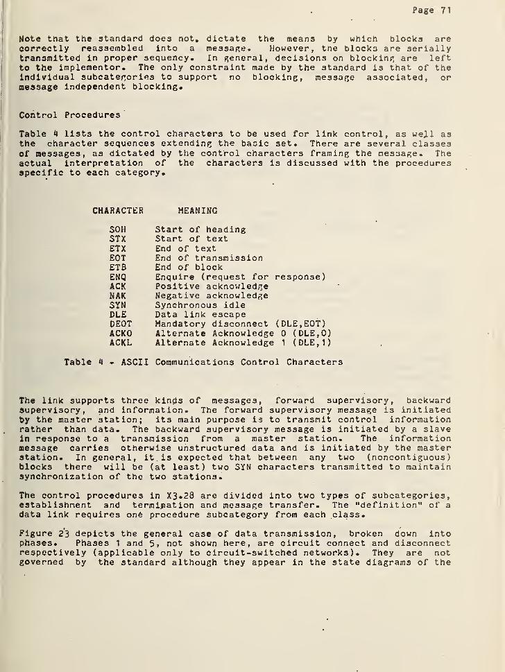
Page 71
Note that the standard does not. dictate the means by which blocks arecorrectly reassembled into a message. However, the blocks are seriallytransmitted in proper sequency. In general, decisions on blocking are leftto the implementor. The only constraint made by the standard is that of theindividual subcategories to support no blocking, message associated, ormessage independent blocking.
Control Procedures
Table 4 lists the control characters to be used for link control, as wejLl asthe character sequences extending the basic set. There are several classesof messages, as dictated by the control characters framing the message. Theactual interpretation of the characters is discussed with the proceduresspecific to each category.
CHARACTER MEANING
SOH Start of headingSTX Start of textETX End of textEOT End of transmissionETB End of blockENQ Enquire (request for response)ACK Positive acknowledgeNAK Negative acknowledgeSYN Synchronous idleDLE Data link escapeDEOT Mandatory disconnect (DLE, EOT)ACKO Alternate Acknowledge 0 (DLE,Q)ACKL Alternate Acknowledge 1 (DLE,1)
Table 4 - ASCII Communications Control Characters
The link supports three kin$ls of messages, forward supervisory, backwardsupervisory, and information. The forward supervisory message is initiatedby the master station; its main purpose is to transmit control informationrather than data. The backward supervisory message is initiated by a slavein response to a transmission from a master station. The informationmessage carries otherwise unstructured data and is initiated by the masterstation. In general, it. is expected that between any two (noncontiguous)blocks there will be (at least) two SYN characters transmitted to maintainsynchronization of the two stations.
The control procedures in X3.28 are divided into two types of subcategories,establishment and termination and message transfer. The "definition" of a
data link requires one procedure subcategory from each class.
Figure 23 depicts the general case of data transmission, broken down intophases. Phases 1 and 5, not shown here, are circuit connect and disconnectrespectively (applicable only to circuit-switched networks). They are notgoverned by the standard although they appear in the state diagrams of the
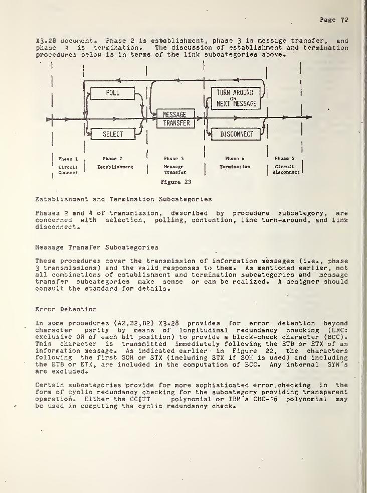
Page 72
X3.28 document. Phase 2 is establishment,phase 3 is message transfer, and
phase 4 is termination. The discussion of establishment and terminationprocedures below is in terms of the link subcategories above.
Establishment and Termination Subcategories
Phases 2 and 4 of transmission, described by procedure subcategory, areconcerned with selection, polling, contention, line turn-around, and linkdisconnect.
Message Transfer Subcategories
These procedures cover the transmission of information messages (i.e., phase3 transmissions) and the valid . responses to them. As mentioned earlier, notall combinations of establishment and termination subcategories and messagetransfer subcategories make sense or can be realized. A designer shouldconsult the standard for details.
Error Detection
In some procedures (A2,B2,B2) X3«28 provides for error detection beyondcharacter parity by means of longitudinal redundancy checking (LRC:exclusive OR of each bit position) to provide a block-check character (BCC).This character is transmitted immediately following the ETB or ETX of aninformation message. As indicated earlier in Figure 22, the charactersfollowing the first SOH or STX (including STX if SOH is used) and includingthe ETB or ETX, are included in the computation of BCC. Any internal SYN'sare excluded.
Certain subcategories provide for more sophisticated error . checking in theform of cyclic redundancy checking for the subcategory providing transparentoperation. Either the CCITT polynomial or IBM's CHC-16 polynomial maybe used in computing the cyclic redundancy check.

Page 73
ANSI ADCCP
Bit oriented procedures have been advanced both because of their inherentlyhigher efficiency (in terms of line utilization) and as a way to "startfresh" from the maze of different configurations in X3.28. Until recently,these procedures were limited due to the computational complexity offraming, "bit-stuffing" and CRC computation, but the new microprocessortechnology has opened the way for the widespread application of this type ofprocedure
.
The American National Standards Institute is currently developing a proposedstandard (X3S3»^/589, draft 6, Oct. 15, 1976) called Advanced DataCommunication Control Procedures (ADCCP) which approaches the sane problemas X3.28-1975, where different types of "messages" have different forms(e.g., selection vs. text transfer). The control characters are replacedby a subfield of the ADCCP frame which contains commands or responses tocommands. Stations are identified by another subfield of the frame.
Link Configurations.
In ADCCP a terminal (or station) is permanently designated as being eitherPrimary or Secondary. The Primary station is the control station of thelink and has permanent master status. This might correspond to the AESsystems controller should the systems designer choose to use a digitalserial communications link. Similarly, the Secondary is in permanent slavestatus as could be all of the AES functional controllers.
The Primary station has the responsibility for link initialization, controland organization of data flow, and control of error recovery .procedures atthe link level, including retransmission. The Secondary has theresponsibility to act only on the commands from the Primary, as describedbelow.
ADCCP supports two general link configurations termed Primary/Primary andPrimary/Secondary. The Primary/Primary link shown in Figure 2 4 is referredto as a balanced point-to-point link and consists in reality of twosublinks, each station comprising both a primary and a secondary component.
Figure 24
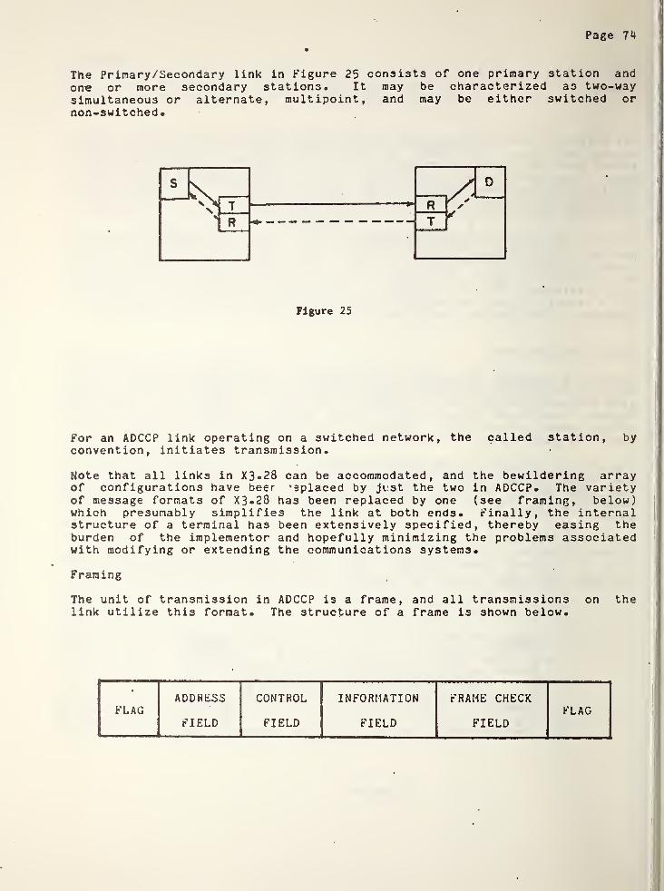
Page 7^
The Primary/Secondary link in Figure 25 consists of one primary station andone or more secondary stations. It may be characterized as two-waysimultaneous or alternate, multipoint, and may be either switched ornon-switched
•
Figure 25
For an ADCCP link operating on a switched network, the called station, byconvention, initiates transmission.
Note that all links in X3*28 can be accommodated, and the bewildering arrayof configurations have beer ’eplaced by ji.st the two in ADCCP* The varietyof message formats of X3*28 has been replaced by one (see framing, below)which presumably simplifies the link at both ends* Finally, the internalstructure of a terminal has been extensively specified, thereby easing theburden of the implementor and hopefully minimizing the problems associatedwith modifying or extending the communications systems.
Framing
The unit of transmission in ADCCP is a frame, and all transmissions on thelink utilize this format. The structure of a frame is shown below.
•
ADDRESS CONTROL INFORMATION FRAME CHECKFLAG FLAG
FIELD FIELD FIELD FIELD

Page 75
Within a frame the fields are as follows.
flag: An 8-bit sequency, 01111110, which begins and ends a frame. Allterminals hunt for the flag in idle state, since this field is used forframe synchronization.
Address Field: An 8-bit sequency identifies a secondary terminal on thelink. It may be extended (recursively) to provide for multiple octets. Thestructure is:
7 Bit Address
Extended: 0 = No1 = Yes
Control Field: Depending on the operational mode, the control field is oneoctet, extendible to two octets to allow for a larger range of sequencenumbers. Note that the bit pattern for a command may be the sane as thatfor a response, so that a knowledge of direction is necessary to interpret a
frame. The control field has three formats; the I format containing thesend and receive sequence numbers that is used for the exchange of data;the S format containing only receive sequency numbers that is used forconveying status and other sequentially dependent link control information;and the U format that does not contain sequence numbers and is used forother control functions such as setting modes or describing abnormal linkconditions. These formats are summarized a.s follows:
(I)
(S)
(U)
prn N* P/F
1/1 L_S
1M
iP/* _JLJ
The FI Field, common to all, dictates the interpretation of the remainingfields. It has three values, indicating an information transfer (I),supervisory (S), or unnumbered (U) frame. In the first case, the remainingfields are:
.N* : Send Sequence Number
P/F : Poll Command (from primary)Last Frame Flag (from secondary)
Nr : Receive Sequence Number
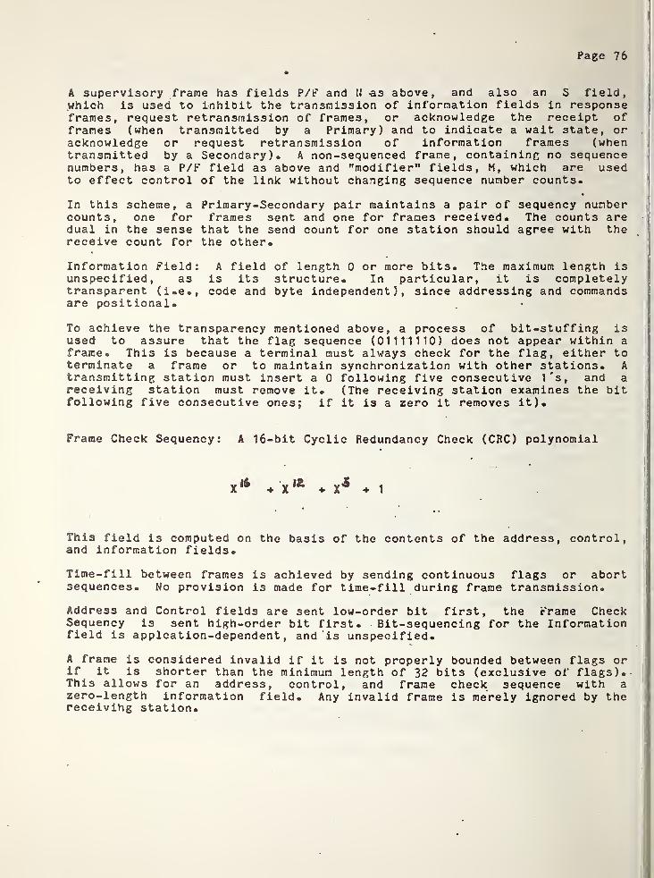
Page 76
A supervisory frame has fields P/P and N -as above, and also an S field,which is used to inhibit the transmission of information fields in responseframes, request retransmission of frames, or acknowledge the receipt offrames (when transmitted by a Primary) and to indicate a wait state, oracknowledge or request retransmission of information frames (whentransmitted by a Secondary). A non-sequenced frame, containing no sequencenumbers, has a P/P field as above and "modifier” fields, M, which are usedto effect control of the link without changing sequence number counts.
In this scheme, a Primary-Secondary pair maintains a pair of sequency numbercounts, one for frames sent and one for frames received. The counts aredual in the sense that the send count for one station should agree with thereceive count for the other.
Information Field: A field of length 0 or more bits. The maximum length isunspecified, as is its structure. In particular, it is completelytransparent (i.e., code and byte independent), since addressing and commandsare positional.
To achieve the transparency mentioned above, a process of bit-stuffing isused to assure that the flag sequence (01111110) does not appear within aframe® This is because a terminal must always check for the flag, either toterminate a frame or to maintain synchronization with other stations. Atransmitting station must insert a 0 following five consecutive 1's, and areceiving station must remove it. (The receiving station examines the bitfollowing five consecutive ones; if it is a zero it removes it).
Frame Check Sequency: A 16-bit Cyclic Redundancy Check (CRC) polynomial
+ XIZ
+ X5
1
This field is computed on the basis of the contents of the address, control,and information fields.
Time-fill between frames is achieved by sending continuous flags or abortsequences. No provision is made for time-fill during frame transmission.
Address and Control fields are sent low-order bit first, the Frame CheckSequency is sent high-order bit first. Bit-sequencing for the Informationfield is applcation-dependent
,and is unspecified.
A frame is considered invalid if it is not properly bounded between flags orif it is shorter than the minimun length of 32 bits (exclusive of flags).This allows for an address, control, and frame check sequence with azero-length information field. Any invalid frame is merely ignored by thereceiving station.
Page 77
Error Detection
ADCCP provides the 16-bit CRC for detecting errors in transmission. Inaddition, a Response Timer is specified for the Primary, to detect noresponse from the Secondary. The sequential numbering scheme also helpsdetect lost or duplicated frames. An Abort sequence is provided (1111111)which allows a transmitting station to terminate transmission abnormally.The receiving station is expected to ignore an aborted frame.
Error Recovery
No provisions for recovery other than retransmission are made. The negativeackntpwledgements allow the Primary to decide whether retransmission willcorrect an error (short-term vs. long-term,- and Link level vs. Higherlevel )
•
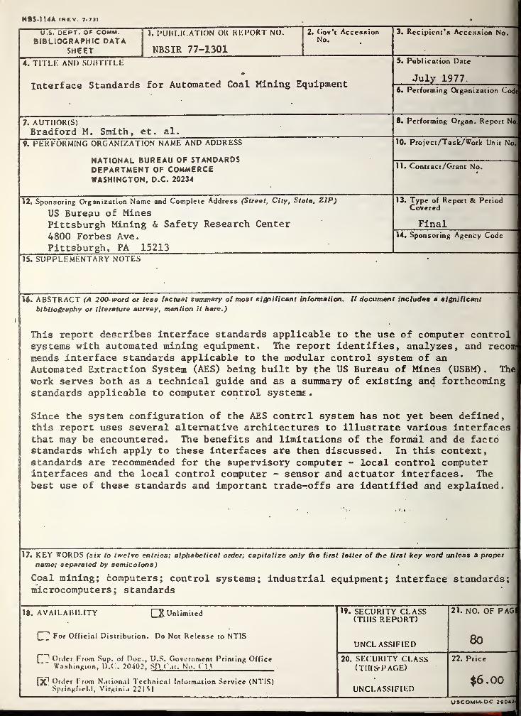
NBS-114A (rev. 7-73)
U.S. DEPT. OF COMM.BIBLIOGRAPHIC DATA
SHEET
1. PUBLICATION OK REPORT NO.
NBSIR 77-1301
2. Gov’t AccessionNo.
3. Recipient’s Accession No.
4. TITLE AND SUBTITLE S. Publication Date
Interface Standards
<s>
for Automated Coal Mining EquipmentJuly 1977
6. Performing Organization Code
7. AUTHOR(S)Bradford M. Smith, et. al.
8. Performing Organ. Report No
9. PERFORMING ORGANIZATION NAME AND ADDRESS
NATIONAL BUREAU OF STANDARDSDEPARTMENT OF COMMERCEWASHINGTON, D.C. 20234
10. Project/Task/Work Unit No.
11. Contract /Grant No.
12. Sponsoring Organization Name and Complete Address (Street, City, State, ZIP)
US Bureau of MinesPittsburgh Mining & Safety Research Center
13. Type of Report Be PeriodCovered
Final
4800 Forbes Ave.
Pittsburgh, PA 15213
14. Sponsoring Agency Code
15. SUPPLEMENTARY NOTES
16. ABSTRACT (A 200-word or less factual summary of most significant information. If document includes a significant
bibliography or literature survey, mention it here.)
This report describes interface standards applicable to the use of computer controlsystems with automated mining equipment. The report identifies, analyzes, and recommends interface standards applicable to the modular control system of anAutomated Extraction System (AES) being built by the US Bureau of Mines (USBM) . The
work serves both as a technical guide and as a summary of existing and forthcomingstandards applicable to computer control systems
.
Since the system configuration of the AES centre 1 system has not yet been defined,this report uses several alternative architectures to illustrate various interfacesthat may be encountered. The benefits and limitations of the formal and de factostandards which apply to these interfaces are then discussed. In this context,standards are recommended for the supervisory computer - local control computerinterfaces and the local control computer - sensor and actuator interfaces. Thebest use of these standards and important trade-offs are identified and explained.
17. KEY WORDS (six to twelve entries; alphabetical order; capitalize only the first letter of the first key word unless a proper
name; separated by semicolons
)
Coal mining; computers; control systems; industrial equipment; interface standards;microcomputers; standards
1 18. AVAILABILITY Q Unlimited 19. SECURITY CLASS 21. NO. OF PAG(THIS REPORT)
80[
' For Official Distribution. Do Not Release to NTISUNCL ASSIFIED
Q-
* Order From Sup. of Doc., U.S. Government Printing Office 20. SECURITY CLASS 22. PriceWashington, D.C!. 20402. SD Cat. No. (14 (THISPAGE)
fX1 Order From National Technical Information Service (NTIS) $6.00Springfield, Virginia 221M UNCLASSIFIED
U3COMM.DC 20042-