Interceptor Vertical Laminar Flow - Kewaunee The Interceptor Vertical Laminar Flow Clean Bench is...
34
KEWAUNEE ® encouraging new discovery ...Worldwide Interceptor ® Vertical Laminar Flow CLEAN BENCH User & Operation Manual INT-0600-VLF INT-0600-VLF-230 INT-0900-VLF INT-0900-VLF-230 INT-1200-VLF INT-1200-VLF-230 INT-1500-VLF INT-1500-VLF-230 INT-1800-VLF INT-1800-VLF-230 VLFUO-0316
Transcript of Interceptor Vertical Laminar Flow - Kewaunee The Interceptor Vertical Laminar Flow Clean Bench is...

KEWAUNEE®
encouraging new discovery ...Worldwide
Interceptor®
Vertical Laminar FlowCLEAN BENCH
User & Operation Manual INT-0600-VLF INT-0600-VLF-230
INT-0900-VLF INT-0900-VLF-230INT-1200-VLF INT-1200-VLF-230 INT-1500-VLF INT-1500-VLF-230INT-1800-VLF INT-1800-VLF-230
VLFUO-0316


Table of ContentsCHAPTER 1
Product Description 1.1Technical Specifications 1.2
CHAPTER 2Safety, Ergonomics and Reliability 2.1Room Location 2.2
CHAPTER 3Unpack and Inspection 3.2Assembly and Setup 3.3
CHAPTER 4Cabinet Operation and Air Flow Pattern 4.1Startup Procedure 4.3
Chapter 5Care & Maintenance 5.1Required Maintenance 5.2Maintenance Log 5.3HEPA Filters 5.4
CHAPTER 6Troubleshooting and Technical Support 6.1 Detailed View 6.2 Replaceable Parts List 6.3Wiring Schematics 6.4Warranty 6.6 Warranty Registration 6.7
AddendumOptional Base Stand Assembly A.1 Fan Speed Adjustment B.1

NOTICE:The Interceptor Vertical Laminar Flow Clean Bench is designed to enhance performance, safety, and operator comfort. Due to the nature of the work performed in a Vertical Laminar Flow clean bench, it is important to read the User and Operation Manual and follow standard Operating Procedures to avoid compromising work and potential injuries.
If this equipment is used in a manner not specified by the manufacturer in this manual, the protection provided by the equipment may be impaired. Also, any maintenance or service to an Interceptor Vertical Laminar Flow product must be done according to the instructions contained herein. Maintenance of this product shall be carried out by technicians trained in the mechanical details of this unit.

User and Operation Manual Chapter 1
Interceptor Vertical Laminar Flow Clean BenchMarch 2016 1.1
CHAPTER 1
Product DescriptionInterceptor® Vertical Laminar Flow Clean Bench manufactured by Kewaunee Scientific Corporation
Part Numbers:• INT-0600-VLF 2 foot Vertical Laminar Flow Superstructure 120 Volt
• INT-0900-VLF 3 foot Vertical Laminar Flow Superstructure 120 Volt
• INT-1200-VLF 4 foot Vertical Laminar Flow Superstructure 120 Volt
• INT-1500-VLF 5 foot Vertical Laminar Flow Superstructure 120 Volt
• INT-1800-VLF 6 foot Vertical Laminar Flow Superstructure 120 Volt
• INT-0600-230-VLF 2 foot Vertical Laminar Flow Superstructure 230 Volt
• INT-0900-230-VLF 3 foot Vertical Laminar Flow Superstructure 230 Volt
• INT-1200-230-VLF 4 foot Vertical Laminar Flow Superstructure 230 Volt
• INT-1500-230-VLF 5 foot Vertical Laminar Flow Superstructure 230 Volt
• INT-1800-230-VLF 6 foot Vertical Laminar Flow Superstructure 230 Volt
Product comes standard with:• HEPA filters
• Filter Pressure Gauge
• Light Switch
• Blower Switch
Optional Features:• Adjustable Height Base Stand
• Worksurface (Kemresin® or 304 Stainless Steel)
• Casters
• Footrest
• IV Pole
• UV Germicidal Light Kit

Chapter 1 User and Operation Manual
Interceptor Vertical Laminar Flow Clean BenchMarch 20161.2
Technical Specifications for VLF Clean Bench
Product Number Width ofSuperstructure
Height of Superstructure
Depth of Superstructure
FanMax HP
Fan and Light current/power
INT-0600-VLF 120 VAC
610 mm24”
937 mm36.875”
724 mm28.5” .134 1.88 Amps
INT-0900-VLF 120 VAC
914 mm36”
937 mm36.875”
724 mm28.5” .268 2.76 Amps
INT-1200-VLF120 VAC
1219 mm48”
937 mm36.875””
724 mm28.5” .268 2.76 Amps
INT-1500-VLF 120 VAC
1524 mm60”
937 mm36.875”
724 mm28.5” .268 2.76 Amps
INT-1800-VLF 120 VAC
1829 mm72”
937 mm36.875”
724 mm28.5” .402 3.64 Amps
INT-0600-VLF-230 230 VAC
610 mm24”
937 mm36.875”
724 mm28.5” .134 1.38 Amps
INT-0900-VLF-230 230 VAC
914 mm36”
937 mm36.875”
724 mm28.5” .268 1.76 Amps
INT-1200-VLF-230230 VAC
1219 mm48”
937 mm36.875”
724 mm28.5” .268 1.76 Amps
INT-1500-VLF0230 230 VAC
1524 mm60”
937 mm36.875”
724 mm28.5” .268 1.76 Amps
INT-1800-VLF-230 230 VAC
1829 mm72”
937 mm36.875”
724 mm28.5” .402 2.14 Amps
Table 1.1: Product Descriptions
NOTES:
All power values measured at 10 inch operating sash height.
If UV option is on your VLF, be sure safety overrides are never immobilized! UV lamp should NEVER be on without cover in place.
¡i AttentionBecause of the weight and size of the Vertical Laminar Flow Clean Bench and the stand, it is recommended that they be moved and lifted only with two or more people. Clean Bench and stand weights are listed in the table below:
Interceptor® VLF Clean Bench WeightsClean Bench
SuperstructureClean Bench
StandWorksurfaceKemresin/SS
Part Number Shipping Weight
Installed Weight
Shipping Weight
Installed Weight
Shipping Weight
Installed Weight
INT-0600-VLF 260 lb 200 lb 58 lb 50 lb 55 lb 50 lb
INT-0900-VLF 315 lb 250 lb 65 lb 55 lb 80 lb 75 lb
INT-1200-VLF 370 lb 300 lb 72 lb 60 lb 105 lb 100 lb
INT-1500-VLF 425 lb 350 lb 79 lb 65 lb 130 lb 125 lb
INT-1800-VLF 480 lb 400 lb 85 lb 70 lb 160 lb 150 lbTable 1.2 Clean Bench Weights

User and Operation Manual Chapter 2
Interceptor Vertical Laminar Flow Clean BenchMarch 2016 2.1
CHAPTER 2
Safety, Ergonomic, and Reliability FeaturesKewaunee’s Interceptor® Vertical Laminar Flow Clean Bench product line is engineered to provide the utmost in reliability; a product that is carefully designed with many enhancements to ensure the operator’s safety.
• 10° Angled Sash for ease of viewing and superior ergonomic working conditions.
• Minihelic Gauge indicating filter pressure.
• Supply HEPA filters with minimum 99.99% efficiency at 0.3 microns.
• Optional bases with manually controlled height adjustment. Range of adjustment for better ergonomics; ADA compliant.
• T5 fluorescent light. Energy efficient with brighter illumination than T8 bulb.
• Armrest. Promotes good working posture and reduces stress points.
• Reduced noise and vibration. Interceptor® VLF Clean Bench design allows operator to work longer and more comfortably.
TipsThe following are recommended for control of ergonomic-related issues associated with the use of Vertical Laminar Flow Clean Bench:
• Use an ergonomically designed chair that provides adequate back support, adjustable seat angle, and height adjustability between 18 inches to 28 inches.
• Place anti-fatigue matting in areas for users who must stand for extended periods of time.
• Take frequent mini-breaks to perform stretching.
• Proper posture should always be practiced. Use of footrest when working seated is recommended.
• Upper shoulders and upper arms should be relaxed; ensure chair seat height is aligned properly to provide no stress to upper shoulders or upper arms when forearms are resting on tabletop (wrist should always align with forearm – think straight, horizontal line).

Chapter 2 User and Operation Manual
Interceptor Vertical Laminar Flow Clean BenchMarch 20162.2
Room LocationIt is imperative that the Vertical Laminar Flow Clean Bench be placed in the correct location within the room. Ideally the location of the cabinet will be away from any type of room air turbulence and out of high traffic areas within the laboratory. Air turbulence can be created by a number of things including; but not limited to, air ducts, doorways, windows and foot traffic. Placing the cabinet in direct path of unstable air flows can cause contamination of the cabinet workspace and/or allow contaminates to escape from the cabinet into the room.
First and foremost always refer to your facilities Standard Operating Procedures (SOP). Always use best housekeeping practices. Never store items on top of the cabinet. If you have questions about cabinet location, please contact Kewaunee Scientific Corporation at [email protected] or 704-873-7202.
User and Operation Manual Chapter 3
Interceptor Vertical Laminar Flow Clean BenchMarch 2016 3.1
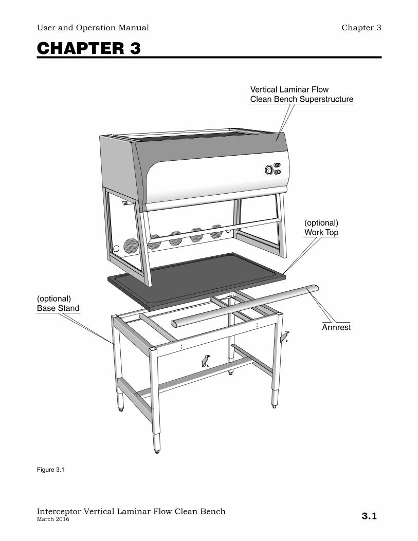
CHAPTER 3
Vertical Laminar FlowClean Bench Superstructure
(optional)Work Top
(optional)Base Stand
Armrest
Figure 3.1

Chapter 3 User and Operation Manual
Interceptor Vertical Laminar Flow Clean BenchMarch 20163.2
Unpack and InspectionWhen unpacking your new Interceptor® Vertical Laminar Flow Clean Bench, it is imperative that a thorough inspection be performed to ensure that there is no freight damage. If any damage is found at time of delivery, it should be noted with the carrier on paperwork. If damage is concealed owner must contact the freight carrier within 15 days of delivery per the United States Interstate Commerce Commission rules and regulations. Kewaunee Scientific Corporation and its dealers are not responsible for damages occurring during shipment.
Miscellaneous Parts Packed in Box Inside CabinetQt Part Number Description
1 050163-00VLF VLF User & Operation Manual - VLFUO-03161 Factory Test Results2 050195-0A Armrest Bracket2 F-7279-00 Armrest End Caps2 970442 #8x1/2” Self-drilling Screws4 970406 5/16" Flat Washers4 F-3808-00 1/4”-20 Hex Nuts
Table 3.1
Parts Packed Loose Inside CabinetQt Part Number Description
1 F-7280-(Length) Aluminum Armrest TubeTable 3.2
If the clean bench was purchased with the optional Work Top and/or Base Stand, locate them as well. See Addendum A for Base Stand parts list and assembly instructions.

User and Operation Manual Chapter 3
Interceptor Vertical Laminar Flow Clean BenchMarch 2016 3.3
Assembly and SetupThe Vertical Laminar Flow Clean Bench should be maneuvered, as close as possible, to its final location with the assistance of either a furniture dolly or floor jack. Attempts to move the unit by tilting it onto a hand truck greatly increases the risk or injury to the handler and damage to the workstation.
1. If optional Adjustable Height Base Stand is used; assemble per Addendum A.
2. Once Base Stand is assembled (if required), place Work Top on base, centered side-to-side, and flush to the front of the stand. Top should be secured to the base with adhesive or screws.
3. Lift the Clean Bench Superstructure (using at least two (2) people) and place on the Work Top, centered side-to-side, and flush with the front edge of the top.
The superstructure may be fastened to the work top with screws (not provided) through holes in the 1" flange at the rear or with adhesive (silicone or epoxy cement).
4. If an existing base and work top are being used, lift the Clean Bench Superstructure (using at least two (2) people) onto the work top and secure using the same method as above.
5. If an existing base is being used, the Armrest may be mounted as instructed in Addendum A, steps 8 thru 11. (Note: modifications may be needed to the existing base if Armrest is used.)
Position VLF Clean Bench: Position the Vertical Laminar Flow Clean Bench in an accessible location free of turbulence as described in Chapter 2. Be sure bench is not located under a make-up air diffuser of any kind. Also, avoid placing the unit next to any frequently used door, high traffic areas, or open windows.
Chapter 3 User and Operation Manual
Interceptor Vertical Laminar Flow Clean BenchMarch 20163.4

User and Operation Manual Chapter 4
Interceptor Vertical Laminar Flow Clean BenchMarch 2016 4.1
CHAPTER 4
VLF Clean Bench OperationTheory of Operation The Interceptor VLF is a Vertical Laminar Flow Clean Bench. Its function is to isolate samples from cross-contamination and protect from being contaminated by particulate material outside the cabinet. It accomplishes this objective by bathing the sample in HEPA filtered clean air while keeping contaminates out by having a continuous substantial outflow of HEPA filtered air through the cabinet.
The VLF will safely operate at a temperature range of 55°F to 85°F (13°C - 29°C) and a relative humidity of 10% to 70%.
Prefilter
Room Air
CleanHEPA Filtered
Air
CleanHEPA Filtered
Air
HEPA Filter
Figure 4.2 Interceptor Vertical Laminar Flow Air Flow Patterns

Chapter 4 User and Operation Manual
Interceptor Vertical Laminar Flow Clean BenchMarch 20164.2
Figure 4.1 VLF Front View
Light Switch
Blower SwitchMinihelic Differencial Pressure Gauge
OptionalBase Stand
Armrest
Cable Port
Sash
SashSoft-down Stay
Optional UV Lamp
Work Top
T5 Fluorescent Lamp

User and Operation Manual Chapter 4
Interceptor Vertical Laminar Flow Clean BenchMarch 2016 4.3
Startup Procedure
Make sure the Clean Bench plugged into an appropriate electrical outlet and that there is power to the receptacle. Close the hinged Sash. Turn the fan on. The fan motor will start.
(Note: 120 volt cabinets are supplied with a power cord with a plug. 230 volt units are supplied with a power cord, but without a plug. Have a qualified electrician install an appropriate plug to match the electrical outlet receptacle.)
The Interceptor ® Laminar Flow Clean Bench is now intercepting all dust, bacteria, and viral matter and delivering HEPA filtered, clean air to the cabinet interior.
The fans are activated and deactivated by the lower Blower Switch. The interior light is activated by the upper Light Switch. The sash should always be in the closed position before undertaking an actual procedure in the cabinet.
The Minihelic Differential Pressure Gauge measures the resistance against airflow (static pressure) presented by the HEPA filter. When the static pressure reaches 1.0", the filter should be replaced.
The target down flow velocity is 50 to 65 FPM. Consult your Safety Officer for recommended setting. When the down flow is less than 40 FPM, the fan RPM should be increase by turning the potentiometer, located in the electrical junction box behind the front cover, clockwise until acceptable down flow is returned. A trained service technician should undertake this procedure. Down flow is measured using NSF Standard 49 section A8.
Before initial use, it is recommended the HEPA Filter be leak tested. An initial leak test is performed at the factory, however second leak test should be performed by a qualified technician after the cabinet is setup. The down flow velocity should also be verified before initial use. The use of a calibrated Airflow Monitor is recommended when verifying down flow.
(Note: results of the factory Down Flow and Electrical tests are included in the package with the User & Operation Manual.)

Chapter 4 User and Operation Manual
Interceptor Vertical Laminar Flow Clean BenchMarch 20164.4
Clean Bench Operation Notes1. The Interceptor VLF Clean Bench is designed to provide ISO class 5 Air
consistently over the work area. In order to maintain these conditions, the down flow velocity should be checked on a regular basis. In order to do this, we recommend that a qualified technician test the airflow using a calibrated air flow monitor.
2. The Interceptor VLF is not a Biological Safety Cabinet or a fume hood. This cabinet will not protect the user from unsafe biohazards nor will it protect the user from inhaling fumes. The down flow air will exit the clean bench directly into the users breathing zone. Only non-hazardous work should be performed in this product. Only PRODUCT protection is provided within the Interceptor VLF. PERSONNEL protection is not provided with this product.
3. No acids, toxins, radionuclides or biohazards should ever be used inside this product. Please contact your Safety Officer with questions regarding safe use of the Interceptor VLF.
4. Before any work begins, the Clean Bench should be turned on and allowed to warm up for a minimum of one minute.
If cabinet does not come on, make sure it is plugged into a wall outlet. If it still will not come on, have a qualified person check the breaker within the building’s electrical panel.
5. The Clean Bench should be completely wiped down before and after each use with an approved cleaning solution.
6. If a work surface is provided for the Interceptor VLF, it will be dished to contain spills and to keep all work within the proper work zone.
7. The sash should always be in the down or closed position while working. Opening the sash can cause working conditions inside the cabinet to no longer be Class 5 conditions.
8. Position the Interceptor VLF where it will not be affected by cross drafts, high traffic patterns, and anything that might cause turbulent airflow and affect conditions inside the cabinet.
9. As the filter begins to load it might be necessary to adjust the Speed Controller (Potentiometer) to maintain desired down flow.
10. If the UV light package is included, the front UV cover must be connected to the front of the VLF completely covering any opening. UV light will not come on until cover is properly in place.
11. The UV light is not on a timer and will remain on until front cover is removed.
12. If the Speed Controller is turned up fully and Interceptor can no longer maintain required down flow velocity, it is time to change the filter. Instructions are located on page 6.1

User and Operation Manual Chapter 5
Interceptor Vertical Laminar Flow Clean BenchMarch 2016 5.1
CHAPTER 5
Care and MaintenanceThis chapter details maintenance that can be undertaken by laboratory personnel, supervisors; and/or Accredited Technicians.
Access to Maintenance AreaLift Top Front Panel to access Supply HEPA Filter
Figure 5.1 VLF with Open Top Front Panel
Air Plenum Clamping Bolts Top Front Panel
Supply HEPA FilterAir Plenum

Chapter 5 User and Operation Manual
Interceptor Vertical Laminar Flow Clean BenchMarch 20165.2
Frequently Required Maintenance ProceduresItem Procedure
Filter replacement 1)Raisefrontpanel.(seefigure5.2below)2) Loosen Air Plenum Assembly by loosening Lower Locking Nuts (4) (several
turns) and tightening Upper Locking Nuts (4). This will cause the Air Plenum to rise. (do not turn Plenum Lock Nuts or Air Plenum Clamping Bolts)
3) Remove Filter by sliding forward and replace with a new HEPA Filter. (ensureHEPAfilterisinstalledwithproperairflowasindicatedbyarrowonfilter)
4) Reverse step 2 to ensure a tight seal on both the top and bottom gaskets of the HEPA Filter.
Cabinet interior cleaning NOTE: DO NOT USE CHLORINE BLEACH
a) Use UV disinfecting light for at least 30 minutes or time recommended by your Standard Operating Procedure (SOP) if UV light is installed.
b) Open sash and using disinfectant approved for use in your procedures, carefully clean.
Clean cabinet exterior Use mild soap and approved disinfectant
Table 5.1
Infrequently Required Maintenance ProceduresItem When Required Procedure
Changing lamps Fluorescent lights may be operated until they burn out. UV lights should be replaced when their useful life is exceeded. (Approx: 2000 Hrs)
Disconnect the power cord. Remove pinned UVorfluorescentlampbyturninglamp90°and pulling forward. New lamps are installed by reversing this procedure.
Table 5.2
Figure 5.2 VLF HEPA Filter Replacement
HEPA Filter
Top Front Panel
Air Plenum Assembly
Clamping Bolt
Upper Locking Nut
Lower Locking Nut
Plenum Lock Nut

User and Operation Manual Chapter 5
Interceptor Vertical Laminar Flow Clean BenchMarch 2016 5.3
Maintenance LogWe recommend the formation of a logbook to record recommended maintenance activities as the example shown below:
Month Clean Exterior
January
February
March
April
May
June
July
August
September
October
November
December
Daily Basis: Disinfect surface work areas, before and after each use.
Weekly Basis: Disinfect surface work areas. Clean cabinet exterior
Quarterly Basis: Check lights for proper function. Check for malfunctions. CleanPre-filter.Itmaybewashedwithsoapandwaterandreused. Spot clean stainless steel surfaces.
Annual Basis: Haveaqualifiedtechnicianrecertifycleanbench: •Downflowvelocity • HEPA Filter Leak Test
Table 5.3

Chapter 5 User and Operation Manual
Interceptor Vertical Laminar Flow Clean BenchMarch 20165.4
HEPA FiltersHEPA filters are the most important safeguard of a Vertical Laminar Flow Clean Bench. The HEPA filter has a proven efficiency of 99.99% at 0.3 microns. The HEPA filter is made from a single sheet of borosilicate fibers that have been treated with a wet-strength water–repellent binder. The filter is pleated to increase overall surface inside the filter frame and is protected by corrugated aluminum separators. These separators protect the pleats from collapsing and provide a path for airflow. Although aluminum separators are most common, there are other materials that are acceptable. The filters are then glued to a wood, metal or plastic frame. The filters are very fragile and careless handling can easily compromise their integrity. It is important that the filters be leak tested when initially installed and whenever the cabinet is moved or relocated. Note that much of this information is credited to CDC BMBL 5th Edition.
HEPA filters are only efficient on particulates; they are not designed to filter gases. It is important to check the filters on a regular basis (at least annually during recertification). As the filters collect particulates, it will become increasingly harder to maintain the airflow balance within the cabinet. Filters should be changed at recommended intervals to ensure proper airflow is being maintained within the cabinets.

User and Operation Manual Chapter 6
Interceptor Vertical Laminar Flow Clean BenchMarch 2016 6.1
CHAPTER 6
TroubleshootingProblem Possible Cause Recommended Fix
No lights or fan
a. Unit unplugged Plug it inb. Building breaker open Check outlet breaker
No fans a. Fan breaker/overload tripped Overload will reset if unit disconnected. If condition persists, motor may need to be replaced. Contact KewauneeScientificCorporationforassistance.
Fluorescent light not working
a. Lamp burnt out (look for dark rings at opposite ends of glass fluorescenttube)
Replace lamps
b. Lamp wiring defective Inspect and repairc. Bad lamp ballast (symptom is
intermittent light)Replace ballast located in front panel electrical box
UV light does not illuminate
a. Cover must be installed for UV Lamp to work
Install Cover
b. Lamp burnt out Replace lampc. Lamp wiring defective Inspect and repaird. Bad lamp ballast (symptom is
intermittent light)Replace ballast located in front panel electrical box
Reduced downflowvelocity
a.HEPAfilterloaded IncreasemotorRPMorreplacefilterif40fpm face velocity is no longer achievable
Contaminationof work insidethe cabinet
a.Loadedsupplyfilter Replacefilterb.Tornsupplyfilter Replacefilterc. Room turbulence Decrease turbulence or move cabinetd. Filter not seated properly Performfilterleaktest
Table 6.1
Technical Support To validate your warranty, please take a moment to register your Vertical Laminar Flow Clean Bench. Registering your enclosure will allow us to provide you with maintenance information and product updates.
To register, fill out the registration form at the end of this section and mail or fax to the address listed at the bottom of the form. If assistance is necessary, please contact us at 704-873-7202.

Chapter 6 User and Operation Manual
Interceptor Vertical Laminar Flow Clean BenchMarch 20166.2
Detailed View of Clean Bench Parts
Figure 6.1
Fan Switch Assembly
Light Switch Assembly
DifferencialPressure Gauge
Junction Box Cover
Front Cover Prop
T5 Fluorescent Lamp
PolyesterAir Filter Pad
Poly Duct Collar
UV HorizontalRaceway
UV Vertical Raceway
Supply Air Blower Assembly
Side Glass
Sash GlassSoft-down Stay
Sash Glass Assembly
Sash Bumper
T8 UV Lamp
Cable GrommetAluminum Armrest Armrest Bracket
Armrest End Cap
Front Cover
Figure 6.2
ElectricalJunction Box
T5 Fluorescent Ballast
T8 UV Ballast
UV 24VPower M
otor
Cap
acito
r
Light RelayBlower Relay
Potentiometer
UV Light Relay
Variable ACPower Control
HEPA Filter

User and Operation Manual Chapter 6
Interceptor Vertical Laminar Flow Clean BenchMarch 2016 6.3
Replaceable Parts ListPart Numbers
Parts INT-0600-VLF INT-0900-VLF INT-1200-VLF INT-1500-VLF INT-1800-VLF
T5 Fluorescent Lamp F-6347-22 F-6347-22 F-6347-34 F-6347-46 F-7248-00
Polyester Air Filter Pad F-7321-02 F-7321-02 F-7321-02 F-7321-02 F-7321-02
Supply HEPA Filter F-7276-24VLF F-7276-36VLF F-7276-48VLF F-7276-60VLF F-7276-72VLF
Sash Glass Assy 050300-A3-2 050300-A3-3 050300-A3-4 050300-A3-5 050300-A3-6
Sash Glass Soft-Down Stay F-7357-00 F-7357-00 F-7357-00 F-7357-00 F-7357-00
Sash Bumper F-7349-00 F-7349-00 F-7349-00 F-7349-00 F-7349-00
Front Cover Prop 050339-00 050339-00 050339-00 050339-00 050339-00
Side Glass 050317-00 050317-00 050317-00 050317-00 050317-00
Aluminum Armrest F-7280-24-VLF F-7280-36-VLF F-7280-48-VLF F-7280-60-VLF F-7280-72-VLF
Armrest Bracket 050195-0A 050195-0A 050195-0A 050195-0A 050195-0A
Armrest Plastic End Cap F-7279-00 F-7279-00 F-7279-00 F-7279-00 F-7279-00
Differential Pressure Gauge F-7318-00 F-7318-00 F-7318-00 F-7318-00 F-7318-00
Light Switch Assy F-7341-00 F-7341-00 F-7341-00 F-7341-00 F-7341-00
Fan Switch Assy F-7341-01 F-7341-01 F-7341-01 F-7341-01 F-7341-01
Poly Duct Collar F-0514-00 F-0514-00 F-0514-00 F-0514-00 F-0514-00
Supply Air Blower Assembly F-7347-00 F-7347-00 F-7347-00 F-7347-00 F-7347-00
Cable Grommet F-7371-00 F-7371-00 F-7371-00 F-7371-00 F-7371-00
Junction Box Cover 050336-24 050336-00 050336-00 050336-00 050336-00
Variable AC Power Control F-7238-00 F-7238-00 F-7238-00 F-7238-00 F-7238-00
Potentiometer F-7239-00 F-7239-00 F-7239-00 F-7239-00 F-7239-00
10µF Motor Capacitor F-7340-00 F-7340-00 F-7340-00 F-7340-00 F-7340-00
Fluorescent Ballast F-7231-02 F-7231-00 F-7231-00 F-7231-00 F-7231-00
Fluorescent Relay F-7353-00 F-7353-00 F-7353-00 F-7353-00 F-7353-00
Fan Relay F-7353-00 F-7353-00 F-7353-00 F-7353-00 F-7353-00
* T8 UV Lamp F-7249-18 F-7249-18 F-7249-00 F-7249-00 F-7249-00
* UV Safety Shield † 050346-24 050346-36 050346-48 050346-60 050346-72
* UV Magnetic Contact † F-7367-00 F-7367-00 F-7367-00 F-7367-00 F-7367-00
* UV Horizontal Raceway 050348-24 050348-36 050348-48 050348-60 050348-72
* UV Vertical Raceway 050349-00 050349-00 050349-00 050349-00 050349-00
* UV Ballast F-7231-01 F-7231-01 F-7231-01 F-7231-01 F-7231-01
* UV Relay F-7353-01 F-7353-01 F-7353-01 F-7353-01 F-7353-01
* UV 24V Power Supply F-7241-00 F-7241-00 F-7241-00 F-7241-00 F-7241-00
Table 6.2 * supplied with clean bench with UV option † not shown

Chapter 6 User and Operation Manual
Interceptor Vertical Laminar Flow Clean BenchMarch 20166.4
Wiring Schematic

Interceptor Vertical Laminar Flow Clean BenchMarch 2016 6.5
User and Operation Manual Addendum 6
Wiring Schematic

Chapter 6 User and Operation Manual
Interceptor Vertical Laminar Flow Clean BenchMarch 20166.6
WARRANTYVertical Laminar Flow Clean Bench WarrantyKEWAUNEE SCIENTIFIC CORPORATION warrants, for a period of three (3) years beginning at the date of delivery, that this Vertical Laminar Flow Clean Bench shall be free from defects in material and workmanship, excluding certain consumable items due to normal wear and tear, i.e.; filters, UV lamps, fluorescent lamps, etc. KEWAUNEE MAKES NO OTHER WARRANTY, EXPRESS OR IMPLIED, WRITTEN OR ORAL, INCLUDING, BUT NOT LIMITED TO, THOSE OF MERCHANTABILITY OR FITNESS FOR ANY PARTICULAR PURPOSE. Purchaser shall notify Kewaunee immediately of any defective product. Kewaunee shall be given reasonable opportunity to inspect the product prior to its return. No product shall be returned to Kewaunee until receipt by purchaser of written shipping instructions from Kewaunee. PURCHASER’S EXCLUSIVE REMEDY, AND KEWAUNEE’S SOLE LIABILITY, SHALL BE, AT KEWAUNEE’S SOLE OPTION, REPAIR OR REPLACEMENT OF THE NON-CONFORMING PRODUCTS OR THEIR PARTS, OR REFUND OF THE PURCHASE PRICE. KEWAUNEE SHALL NOT BE LIABLE FOR ANY INCIDENTAL OR CONSEQUENTIAL DAMAGES, LOSSES OR EXPENSES WHETHER INCURRED IN CONNECTION WITH INJURY TO PERSONS OR PROPERTY.
Returned or Damaged GoodsGoods cannot be accepted without a Return Authorization ticket. Unauthorized returns will not be accepted. Claims for cabinet(s) damaged in transit must be filed with the freight carrier as Kewaunee Scientific Corporation and its dealers are not responsible for damages occurring during shipment.
Claims must be filed with the freight carrier with fifteen (15) days of delivery per the United States Interstate Commerce Commission rules and regulations.
Limitations of LiabilityAll users of this equipment are required to become familiar with any regulations that concern the disposal of waste materials in or surrounding water, land, or air, and to comply with such regulations. The disposal and/or emission of substances used in connection with this equipment may be governed by various federal, state, and/or local entities. Kewaunee Scientific Corporation shall be held harmless with regard to user’s compliance to regulations and/or use.

Kewaunee Interceptor ® Vertical Laminar Flow Clean Bench
Warranty RegistrationPRODUCT DESCRIPTION KEWAUNEE DEALERModel Number Company Name
I N T -Serial Number Contact Name
Date of Purchase (mm/dd/yyyy) Phone Number Extention
/ / - -
CUSTOMER CONTACT INFORMATIONCompany Name
Street Address
City State Zip Code
-Contact Name
Phone Facsimile
OPTIONAL INFORMATION
How did you hear about us?
Do you currently own other Kewaunee Scientific Corporation products? Yes No
Would you like to receive Kewaunee Scientific Corporation product information? Yes No
Thank you for taking time to register your new product. Please contact Kewaunee Scientific Corporation at 704-873-7202 or visit our website @ www.kewaunee.com if you have any questions.
Please mail or fax completed form to: Kewaunee Scientific Corporation 2700 West Front Street
Statesville, North Carolina 28677 Tele: 704.873.7202 • Fax: 704.873.5160 Website: www.kewaunee.com Email: [email protected]


Interceptor Vertical Laminar Flow Clean BenchMarch 2016 A.1
User and Operation Manual Addendum A
Optional Base Stand Assembly Instructions
Figure A.1
Right HandLeg Assembly
Apron Rail
Left HandLeg Assembly
Armrest Tube
Armrest Bracket
ArmrestEnd Cap
ArmrestEnd Cap
Armrest Bracket
Apron Rail
Leg Spreader
Apron StrutApron Strut
Adjustable Legwith Bullet Foot
Base Stand PartsQt Part Number Description
1 050267-0L Left Hand Leg Assembly1 050267-0R Right Hand Leg Assembly4 050263-00 Adjustable Leg with Foot2 050264-(Length) Apron Rail (Front & Back)2* 050265-00 Apron Strut1 050266-(Length) Leg Spreader
Table A.1 * Qt of 3 on INT-BASE-1500 and INT-BASE-1800
Base Stand HardwareQt Part Number Description
8† 970301 1/4"-20 x 1/2" Truss Head Bolt12† 970434 1/4"-20 Flanged Tensilock Nut16 970505 1/4”-20 x 1/2” Serrated Hex Bolt8 970507 1/4"-20 J-Style Clip-on Nut
Table A.2 † plus 2 on INT-BASE-1500 and INT-BASE-1800
Arm Rest Parts (packed with Clean Bench)Qt Part Number Description Qt Part Number Description
1 F-7280-(Length) Aluminum Armrest Tube 2* 970442 #8x1/2” Self-drilling Screws2* 050195-0A Armrest Bracket 4† 970406 5/16" Flat Washers2 F-7279-00 Armrest End Cap 4† F-3808-00 1/4”-20 Hex Nuts
Table A.3 * Qt of 3 on INT-BASE-1500 and INT-BASE-1800 † Qt of 6 on INT-BASE-1500 and INT-BASE-1800

Interceptor Vertical Laminar Flow Clean BenchMarch 2016A.2
Addendum A User and Operation Manual
Optional Base Stand Assembly Instructions1. Locate the two Leg Assemblies and position them
with the adjustment holes to the rear.
2. Insert the (4) Adjustable Legs into the Leg Assemblies and fasten them at the desired height using two (2) 1/4"-20 x 1/2" Serrated Hex Bolts in each leg. (see Figure A.2)
3. Slide the 1/4"-20 Clip-nut onto the leg assembly tabs. (see Figure A.3.) Make sure the hole in Clip-nut is aligned with the hole in the tab.
4. Slide Apron Rails over the tabs on the Leg Assemblies and fasten using two (2) 1/4"-20 x 1/2" Serrated Hex Bolts at each end of the Apron Rail. Be sure the notched edge of the Apron Rail is faced down toward the bottom of the table.
5. Position the Leg Spreader between the Leg Assemblies and fasten using four (4) 1/4"-20 x 1/2" Truss Head Bolts, and four (4) 1/4"-20 Tensilock Flanged Nuts. (see Figure A.1)
6. Position the Apron Struts between the front and rear Apron Rails so the bolt holes align
7. Fasten the Apron Struts to the rear Apron Rail with (2) 1/4"-20 x 1/2" Truss Head Bolts and two (2) 1/4"-20 Tensilock Flanged Nuts per strut. (see Figure A.1)
8. Insert the studs on the Armrest Brackets into the holes on the front Apron Rail and fasten with two (2) 1/4"-20 Hex Nuts and Flat Washers per bracket.
9. Place the Aluminum Armrest Tube onto the Armrest Brackets and center horizontally.
10.Fasten the Armrest Tube to the Armrest Brackets using one (1) #8 x 1/2" Self-drilling Screw through the hole in the top of the each bracket into the channel in the bottom of the Armrest Tube.
11.Finish the assembly by sliding to two (2) Armrest End Caps on the ends of the Armrest Tube.
Figure A.2
Figure A.3
Leg Assembly
Adjustable Leg
1/4"-20 x 1/2"Serrated Hex Bolt
Leg Assembly
Apron Rail
1/4"-20Clip-nut
1/4"-20 x 1/2"SerratedHex Bolt
notched edgeof Apron Rail
at bottom

Interceptor Vertical Laminar Flow Clean BenchMarch 2016 B.1
User and Operation Manual Addendum B
Fan Speed Adjustment Instructions
1. Open the Front Panel. The Support Brackets will automatically lock into place to hold panel open. (see Figure B.1)
2. Locate the Electrical Junction Box under the Front Panel.
3. Remove the Electrical Junction Box Cover by removing the four (4) nuts (see Figure B.2)
4. Locate Fan Speed Adjustment Potentiometer inside the Electrical Junction Box. (see Figure B.3 - location my vary depending on size of Clean Bench)
5. Turn the Potentiometer clockwise to increase fan speed, counter clockwise to reduce fan speed. (see Figure B.4)
ê! WARNINGAvoid touching any other electrical connections.
6. Replace the Electrical Junction Box Cover and fasten in place with the four (4) nuts that were removed.
7. Close the Front Panel by lifting up slightly and feeding the Support Brackets into the slots.
Figure B.1
Front Panel
Support Bracket
ElectricalJunction Box
Figure B.2
Cover NutsCover Nuts
Electrical JunctionBox Cover
Figure B.3
Figure B.4
IncreaceSpeed
ReduceSpeed
Potentiometer Motor Capacitor
Speed Controller

Interceptor Vertical Laminar Flow Clean BenchMarch 2016B.2
Addendum B User and Operation Manual
Down Flow TestTo determine the actual downflow velocity, airflow velocity readings are take using an anemometer. Readings should be taken 6" below the bottom of the HEPA filter at six inch grid points as shown in the diagram below. The “average downflow velocity” is calculated by averaging the reading.
The number of readings to be taken is based on the size of the Clean Bench:
Clean Bench Size Number of Readings
INT-0600 2'-0" 9
INT-0900 3'-0" 15
INT-1200 4'-0" 21
INT-1500 5'-0" 27
INT-1800 6'-0" 33
The target down flow velocity is 50 to 65 FPM. Consult your Safety Officer for recommended setting. When the down flow is less than 40 FPM, the fan RPM should be increase by turning the potentiometer, located in the electrical junction box behind the front cover, clockwise until acceptable down flow is returned. A trained service technician should undertake this procedure. Down flow is measured using NSF Standard 49 section A8.
Figure B.5 Down Flow Grid Points


LABORATORY PRODUCTS GROUPP.O. Box 1842 • Statesville, NC 28687-1842Phone: 704-873-7202 • Fax: 800-932-3296Email: [email protected]: www.kewaunee.com© Copyright 2016 Printed in U.S.A. VLFUO-0316