INTERBUS BASICS - Remote Monitoring Newsremotemonitoringnews.com/protocols/interbus_basics.pdf ·...
76
INTERBUS BASICS For more information about INTERBUS remote control practical exercises, please refer to http://www.telepraktikum.de. Prof. Dr.-Ing. Reinhard Langmann FH Düsseldorf Process Control Laboratory http://www.teleautomation.de E-mail: [email protected] University of Applied Sciences Process Control Laboratory
Transcript of INTERBUS BASICS - Remote Monitoring Newsremotemonitoringnews.com/protocols/interbus_basics.pdf ·...
INTERBUSBASICS
For more information about INTERBUS remote control practicalexercises, please refer to http://www.telepraktikum.de.
Prof. Dr.-Ing. Reinhard Langmann
FH DüsseldorfProcess Control Laboratoryhttp://www.teleautomation.deE-mail: [email protected]
University of Applied SciencesProcess Control Laboratory

Table of Contents2
Table of Contents 3
1 The History of INTERBUS ..............................................................................................52 General Characteristics ....................................................................................................7
2.1 Main Task ..............................................................................................................................7
2.2 Area of Application...............................................................................................................8
2.3 Method of Operation ..........................................................................................................10
3 System Configuration .....................................................................................................133.1 Bus Elements .......................................................................................................................13
3.2 Bus Segments .......................................................................................................................15
3.3 Network Configuration ......................................................................................................21
4 Data Transmission ..........................................................................................................234.1 Protocol Structure...............................................................................................................23
4.2 Bit Transmission .................................................................................................................24
4.3 Summation Frame Protocol ...............................................................................................25
4.4 Process Data Channel .........................................................................................................27
4.5 Parameter Channel .............................................................................................................28
4.6 Application Interfaces ........................................................................................................30
4.7 Network Management ........................................................................................................31
5 Electrical Configuration.................................................................................................335.1 Protocol Chip.......................................................................................................................33
5.2 Local Bus Devices................................................................................................................35
5.3 Remote Bus Devices ............................................................................................................36
5.4 INTERBUS Loop Devices...................................................................................................37
6 System Components ........................................................................................................396.1 Controller Boards for Open Computer Systems .............................................................39
6.2 PLC Controller Boards ......................................................................................................41
7 Device Modules ...............................................................................................................437.1 Device Modules for Compact Stations ..............................................................................43
7.2 Automation Terminals........................................................................................................44
7.3 Individual Modules .............................................................................................................48
8 Addressing INTERBUS Data .........................................................................................498.1 Addressing Methods ...........................................................................................................50
8.2 Addressing in Programmable Logic Controllers .............................................................52
8.3 Addressing in PC Control Systems ...................................................................................53
9 Device Structure..............................................................................................................559.1 Designing and Planning the System ..................................................................................56
Table of Contents4
9.2 Mounting.............................................................................................................................. 56
9.3 Connection and Cabling ..................................................................................................... 57
10 Diagnostics in INTERBUS Systems ...........................................................................6110.1 INTERBUS Diagnostic Concept .................................................................................... 61
10.2 Visual Indicators ............................................................................................................. 62
10.3 Software Diagnostics ....................................................................................................... 63
11 Open Automation With INTERBUS...........................................................................6511.1 Industrial PC Technology............................................................................................... 65
11.2 Data Interfaces................................................................................................................. 66
12 PC WORX Automation Software ................................................................................6812.1 INTERBUS Configurator............................................................................................... 68
12.2 IEC-61131 Programming ............................................................................................... 69
12.3 Visualization..................................................................................................................... 70
Index.......................................................................................................................................72Appendix.................................................................................................................................75
Appendix A: Important Addresses .............................................................................................................. 75Appendix B: INTERBUS Documentation................................................................................................... 76
1. The History of INTERBUS 5
1 The History of INTERBUS
In 1983, Phoenix Contact began work on a specification for an industrial fieldbus. Workcontinued together with computer manufacturers and technical colleges, and a protocol andhardware definition for a realtime-capable sensor/actuator bus was developed and presentedat the Hanover Fair in 1987. The primary field of application of this bus system - originallyknown as Interbus-S - was to be the speed-optimized time-deterministic transmission ofsensor/actuator data (process data). Over the next few years, an extensive and varied range ofbus components and field devices would be developed by Phoenix Contact and othermanufacturers. Interbus-S developed into one of the world's leading fieldbus systems inindustrial automation.
As the use of open control systems and the development of PC-based automationsolutions increased from around the mid-nineties onwards, the bus system was renamedINTERBUS and a determined focus was placed on distributed automation using factory-wideuniform and standardized communication structures. Milestones in this phase of itsdevelopment include:
1995 Development of INTERBUS Loop (also known as the sensor loop, installation localbus) as a logical extension of INTERBUS "downwards", towards the technicalprocess, for the direct connection of sensors/actuators via a two-wire cable
1996 Launch of the new G4 modules (G4 = Generation 4) for connecting INTERBUS"upwards" with the office world (PC, Ethernet, TCP/IP); founding of the OpenControl User Group
1997 Launch of INTERBUS INLINE, another component based on INTERBUS technologyfor individual and networked automation solutions
The advent of industrial Ethernet technology in the year 2000 considerably encouraged theintegration of INTERBUS and Ethernet/TCP/IP for the creation of consistent communicationstructures for industrial automation.
In parallel with the technical development and functional expansion of INTERBUS,manufacturers and users were becoming involved in a range of complementary activities.These included the foundation of the INTERBUS Club e.V. user organization in Germany in1992 and the development of application profiles (this started in 1992 with the DRIVECOMprofile for electrical drives) by working groups in the INTERBUS Club.
In 1993, the INTERBUS Club started to issue a certification symbol for INTERBUS devicesto indicate conformance and interoperability.
In 1998, INTERBUS became the world's leading fieldbus system with a market share of37.4%. More than 2.5 million devices are in use and 2000 device types are available from1000 manufacturers.

1 The History of INTERBUS6
2 General Characteristics 7
2 General Characteristics
2.1 Main Task
Modern automation requires a continuous flow of information and support for open andflexible control architectures. INTERBUS technology provides an open fieldbus system,which embraces all the process I/Os required for almost any control system.
INTERBUS can be used to connect sensors and actuators via a serial bus cable, to controlmachines and system parts, to network production cells, and to communicate with controlrooms, as well as in production data and machine data acquisition (PDA/MDA). This meansthat INTERBUS is able to fulfill essential requirements of high-performance controlconcepts, as it is:• A cost-effective solution with bus systems, which transmit data serially and reduce the
amount of parallel cabling required• An open and manufacturer-independent networking system, which can easily be
connected with existing control systems• Flexible with regard to future modifications or expansions
INTERBUS is installed in the system to be automated as a compact, single-circuit linefollowing one direction. A controller board provides the interface between a PLC or anindustrial PC (IPC) and INTERBUS. The bus system connects all the I/O componentspresent in the system (also known as INTERBUS devices) with the control/computer systemvia a controller board.
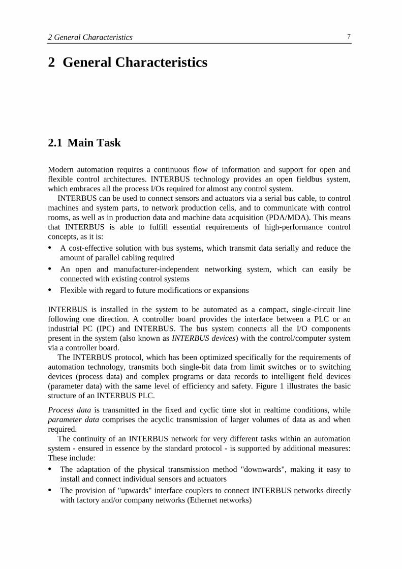
The INTERBUS protocol, which has been optimized specifically for the requirements ofautomation technology, transmits both single-bit data from limit switches or to switchingdevices (process data) and complex programs or data records to intelligent field devices(parameter data) with the same level of efficiency and safety. Figure 1 illustrates the basicstructure of an INTERBUS PLC.
Process data is transmitted in the fixed and cyclic time slot in realtime conditions, whileparameter data comprises the acyclic transmission of larger volumes of data as and whenrequired.
The continuity of an INTERBUS network for very different tasks within an automationsystem - ensured in essence by the standard protocol - is supported by additional measures:These include:• The adaptation of the physical transmission method "downwards", making it easy to
install and connect individual sensors and actuators• The provision of "upwards" interface couplers to connect INTERBUS networks directly
with factory and/or company networks (Ethernet networks)
2 General Characteristics8
• The guarantee of easy configuration, project planning, and diagnostics with uniformsoftware tools
Figure 1: Basic structure of an INTERBUS control system
2.2 Area of Application
With its special features and an extensive product range, INTERBUS has established itselfsuccessfully in all sectors of industry. Its traditional field of application is the automotiveindustry, but INTERBUS is also increasingly being used as an automation solution in otherareas such as materials handling and conveying, the paper and print industry, the food andbeverage industry, building automation, the wood-processing industry, assembly and roboticsapplications, general mechanical engineering and, more recently, in process engineering.Today, INTERBUS is used in over 125,000 applications throughout the world.
In addition to standard applications for connecting a large number of sensors/actuators inthe field to the higher-level control system via a serial bus system, INTERBUS can also beused to fulfill a variety of special application requirements. The examples below illustratesome of its typical applications.
The Use of Optical Fibers
For applications in critical environmental conditions or environments that are subject toelectromagnetic interference, the serial INTERBUS cable can be replaced with optical fibers.Depending on requirements, users can select either a copper or optical fiber transmissionmedium without having to make any changes to the network topology or system structure.Both transmission media can be combined as desired in the network without restriction.
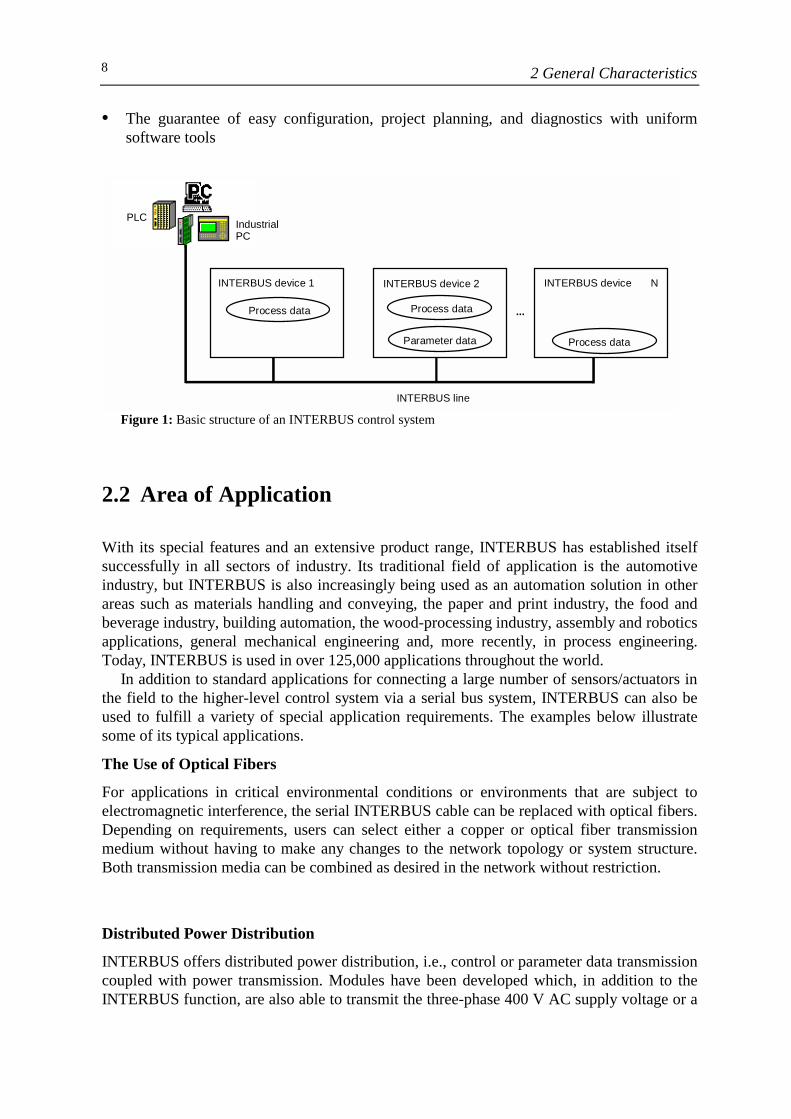
Distributed Power Distribution
INTERBUS offers distributed power distribution, i.e., control or parameter data transmissioncoupled with power transmission. Modules have been developed which, in addition to theINTERBUS function, are also able to transmit the three-phase 400 V AC supply voltage or a
INTERBUS device 1 INTERBUS device 2
Process data Process data
Parameter data
INTERBUS line
...
PLC IndustrialPC
INTERBUS device N
Process data
2 General Characteristics 9
24 V DC voltage from module to module via an additional cable. This eliminates the needfor the star power cabling that was previously used as standard (Figure 2).
Figure 2: Distributed power distribution with INTERBUS
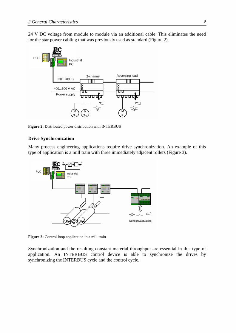
Drive Synchronization
Many process engineering applications require drive synchronization. An example of thistype of application is a mill train with three immediately adjacent rollers (Figure 3).
Figure 3: Control loop application in a mill train
Synchronization and the resulting constant material throughput are essential in this type ofapplication. An INTERBUS control device is able to synchronize the drives bysynchronizing the INTERBUS cycle and the control cycle.
Sensors/actuators
PLCIndustrialPC
-w xy
2-channel
M 3~
M3~
M3~
Reversing loadINTERBUS
Power supply 400...500 V AC
PLC Industrial PC
2 General Characteristics10
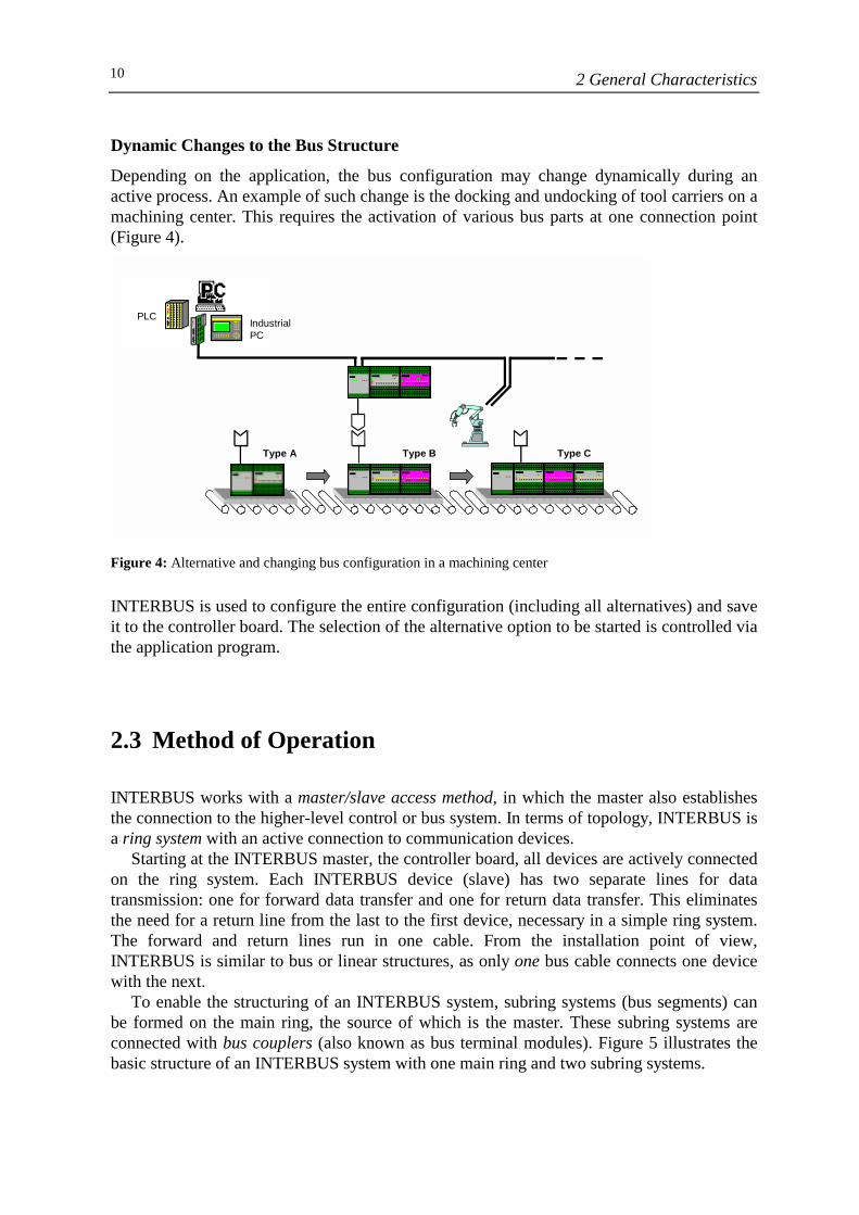
Dynamic Changes to the Bus Structure
Depending on the application, the bus configuration may change dynamically during anactive process. An example of such change is the docking and undocking of tool carriers on amachining center. This requires the activation of various bus parts at one connection point(Figure 4).
Figure 4: Alternative and changing bus configuration in a machining center
INTERBUS is used to configure the entire configuration (including all alternatives) and saveit to the controller board. The selection of the alternative option to be started is controlled viathe application program.
2.3 Method of Operation
INTERBUS works with a master/slave access method, in which the master also establishesthe connection to the higher-level control or bus system. In terms of topology, INTERBUS isa ring system with an active connection to communication devices.
Starting at the INTERBUS master, the controller board, all devices are actively connectedon the ring system. Each INTERBUS device (slave) has two separate lines for datatransmission: one for forward data transfer and one for return data transfer. This eliminatesthe need for a return line from the last to the first device, necessary in a simple ring system.The forward and return lines run in one cable. From the installation point of view,INTERBUS is similar to bus or linear structures, as only one bus cable connects one devicewith the next.
To enable the structuring of an INTERBUS system, subring systems (bus segments) canbe formed on the main ring, the source of which is the master. These subring systems areconnected with bus couplers (also known as bus terminal modules). Figure 5 illustrates thebasic structure of an INTERBUS system with one main ring and two subring systems.
Type A Type B Type C
PLCIndustrialPC
2 General Characteristics 11
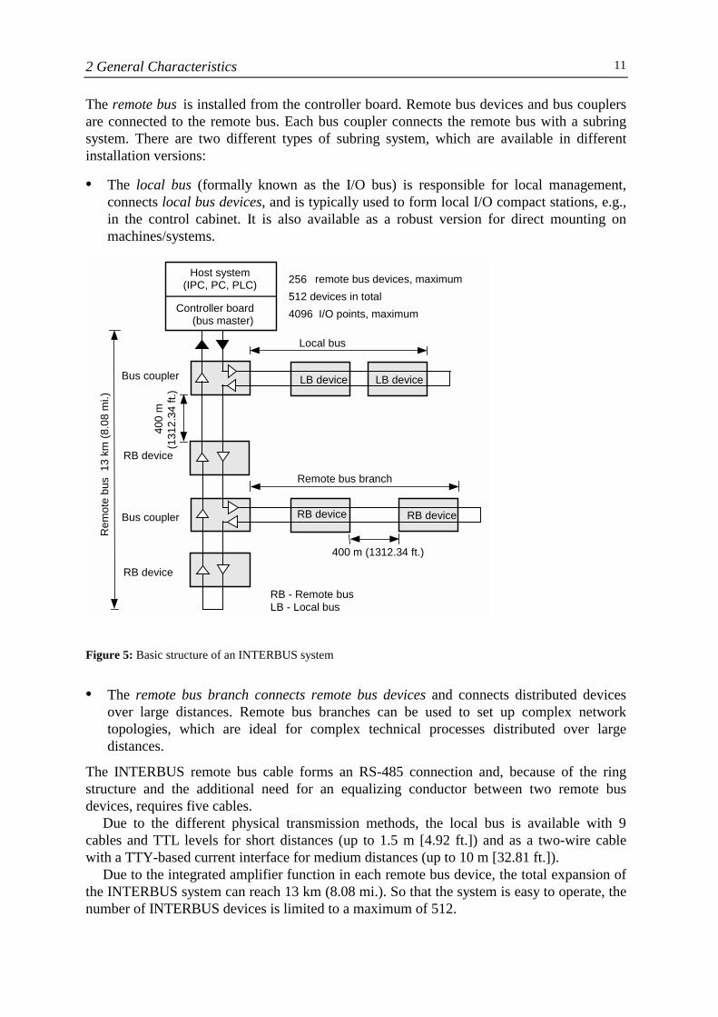
The remote bus is installed from the controller board. Remote bus devices and bus couplersare connected to the remote bus. Each bus coupler connects the remote bus with a subringsystem. There are two different types of subring system, which are available in differentinstallation versions:
• The local bus (formally known as the I/O bus) is responsible for local management,connects local bus devices, and is typically used to form local I/O compact stations, e.g.,in the control cabinet. It is also available as a robust version for direct mounting onmachines/systems.
Figure 5: Basic structure of an INTERBUS system
• The remote bus branch connects remote bus devices and connects distributed devicesover large distances. Remote bus branches can be used to set up complex networktopologies, which are ideal for complex technical processes distributed over largedistances.
The INTERBUS remote bus cable forms an RS-485 connection and, because of the ringstructure and the additional need for an equalizing conductor between two remote busdevices, requires five cables.
Due to the different physical transmission methods, the local bus is available with 9cables and TTL levels for short distances (up to 1.5 m [4.92 ft.]) and as a two-wire cablewith a TTY-based current interface for medium distances (up to 10 m [32.81 ft.]).
Due to the integrated amplifier function in each remote bus device, the total expansion ofthe INTERBUS system can reach 13 km (8.08 mi.). So that the system is easy to operate, thenumber of INTERBUS devices is limited to a maximum of 512.
Host system(IPC, PC, PLC)
Controller board(bus master)
Local bus
256 remote bus devices, maximum512 devices in total
4096 I/O points, maximum
LB device LB device Bus coupler
RB device
Remote bus branch
Bus coupler
RB device
RB device RB device
400 m (1312.34 ft.)
RB - Remote bus LB - Local bus
Rem
ote
bus
13
km (8
.08
mi.)
4
00 m
(1
312.
34 ft
.)
2 General Characteristics12
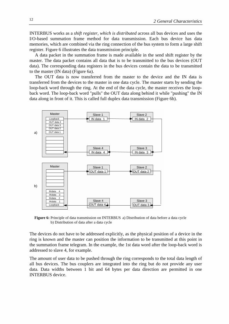
INTERBUS works as a shift register, which is distributed across all bus devices and uses theI/O-based summation frame method for data transmission. Each bus device has datamemories, which are combined via the ring connection of the bus system to form a large shiftregister. Figure 6 illustrates the data transmission principle.
A data packet in the summation frame is made available in the send shift register by themaster. The data packet contains all data that is to be transmitted to the bus devices (OUTdata). The corresponding data registers in the bus devices contain the data to be transmittedto the master (IN data) (Figure 6a).
The OUT data is now transferred from the master to the device and the IN data istransferred from the devices to the master in one data cycle. The master starts by sending theloop-back word through the ring. At the end of the data cycle, the master receives the loop-back word. The loop-back word "pulls" the OUT data along behind it while "pushing" the INdata along in front of it. This is called full duplex data transmission (Figure 6b).
Figure 6: Principle of data transmission on INTERBUS a) Distribution of data before a data cycle b) Distribution of data after a data cycle
The devices do not have to be addressed explicitly, as the physical position of a device in thering is known and the master can position the information to be transmitted at this point inthe summation frame telegram. In the example, the 1st data word after the loop-back word isaddressed to slave 4, for example.
The amount of user data to be pushed through the ring corresponds to the total data length ofall bus devices. The bus couplers are integrated into the ring but do not provide any userdata. Data widths between 1 bit and 64 bytes per data direction are permitted in oneINTERBUS device.
OUT data 4 OUT data 3 OUT data 2 OUT data 1
Loopback Master
IN data 3 IN data 2 IN data 1 Loopback
IN data 4
Master
a)
b)
IN data 4Slave 4
IN data 3 Slave 3
IN data 1Slave 1
IN data 2Slave 2
OUT data 4 Slave 4
OUT data 3Slave 3
OUT data 1 Slave 1
OUT data 2 Slave 2
3 System Configuration 13
3 System Configuration
3.1 Bus Elements
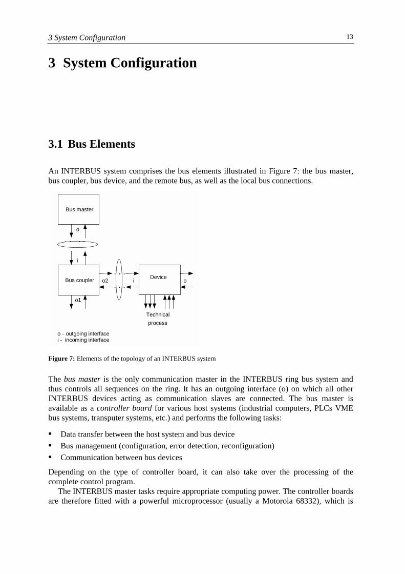
An INTERBUS system comprises the bus elements illustrated in Figure 7: the bus master,bus coupler, bus device, and the remote bus, as well as the local bus connections.
Figure 7: Elements of the topology of an INTERBUS system
The bus master is the only communication master in the INTERBUS ring bus system andthus controls all sequences on the ring. It has an outgoing interface (o) on which all otherINTERBUS devices acting as communication slaves are connected. The bus master isavailable as a controller board for various host systems (industrial computers, PLCs VMEbus systems, transputer systems, etc.) and performs the following tasks:
• Data transfer between the host system and bus device• Bus management (configuration, error detection, reconfiguration)• Communication between bus devices
Depending on the type of controller board, it can also take over the processing of thecomplete control program.
The INTERBUS master tasks require appropriate computing power. The controller boardsare therefore fitted with a powerful microprocessor (usually a Motorola 68332), which is
Bus master
Bus coupler Device
. . . .
. . .
. . .
o1
o
i
o2 i o
Technical process
o - outgoing interface i - incoming interface
3 System Configuration14
responsible solely for the INTERBUS master functions. Essentially, the firmware of thismaster processor shares the functionality and user-friendliness of the INTERBUS system.
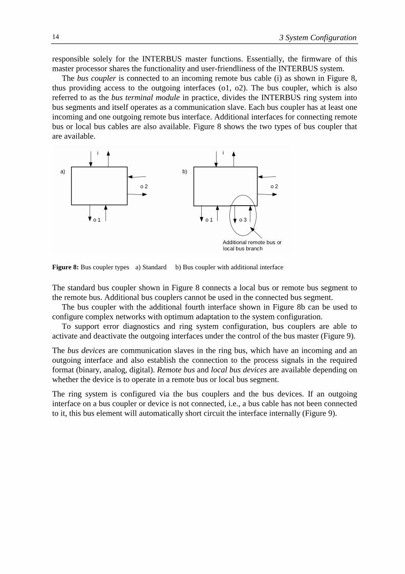
The bus coupler is connected to an incoming remote bus cable (i) as shown in Figure 8,thus providing access to the outgoing interfaces (o1, o2). The bus coupler, which is alsoreferred to as the bus terminal module in practice, divides the INTERBUS ring system intobus segments and itself operates as a communication slave. Each bus coupler has at least oneincoming and one outgoing remote bus interface. Additional interfaces for connecting remotebus or local bus cables are also available. Figure 8 shows the two types of bus coupler thatare available.
Figure 8: Bus coupler types a) Standard b) Bus coupler with additional interface
The standard bus coupler shown in Figure 8 connects a local bus or remote bus segment tothe remote bus. Additional bus couplers cannot be used in the connected bus segment.
The bus coupler with the additional fourth interface shown in Figure 8b can be used toconfigure complex networks with optimum adaptation to the system configuration.
To support error diagnostics and ring system configuration, bus couplers are able toactivate and deactivate the outgoing interfaces under the control of the bus master (Figure 9).
The bus devices are communication slaves in the ring bus, which have an incoming and anoutgoing interface and also establish the connection to the process signals in the requiredformat (binary, analog, digital). Remote bus and local bus devices are available depending onwhether the device is to operate in a remote bus or local bus segment.
The ring system is configured via the bus couplers and the bus devices. If an outgoinginterface on a bus coupler or device is not connected, i.e., a bus cable has not been connectedto it, this bus element will automatically short circuit the interface internally (Figure 9).
a) b)
o 2
i
o 1 o 3
Additional remote bus orlocal bus branch
o 2
o 1
i
3 System Configuration 15
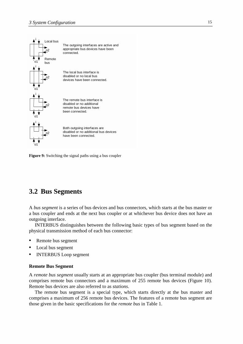
Figure 9: Switching the signal paths using a bus coupler
3.2 Bus Segments
A bus segment is a series of bus devices and bus connectors, which starts at the bus master ora bus coupler and ends at the next bus coupler or at whichever bus device does not have anoutgoing interface.
INTERBUS distinguishes between the following basic types of bus segment based on thephysical transmission method of each bus connector:
• Remote bus segment• Local bus segment• INTERBUS Loop segment
Remote Bus Segment
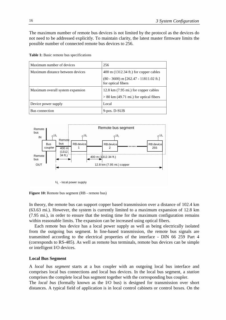
A remote bus segment usually starts at an appropriate bus coupler (bus terminal module) andcomprises remote bus connectors and a maximum of 255 remote bus devices (Figure 10).Remote bus devices are also referred to as stations.
The remote bus segment is a special type, which starts directly at the bus master andcomprises a maximum of 256 remote bus devices. The features of a remote bus segment arethose given in the basic specifications for the remote bus in Table 1.
The outgoing interfaces are active andappropriate bus devices have beenconnected.
o1
i
o2
Local busi
o1
o2
Remotebus
o1
i
o2
o1
i
o2
The local bus interface isdisabled or no local busdevices have been connected.
The remote bus interface isdisabled or no additionalremote bus devices havebeen connected.
Both outgoing interfaces aredisabled or no additional bus deviceshave been connected.
3 System Configuration16
The maximum number of remote bus devices is not limited by the protocol as the devices donot need to be addressed explicitly. To maintain clarity, the latest master firmware limits thepossible number of connected remote bus devices to 256.
Table 1: Basic remote bus specifications
Maximum number of devices 256
Maximum distance between devices 400 m (1312.34 ft.) for copper cables
(80 - 3600) m [262.47 - 11811.02 ft.]for optical fibers
Maximum overall system expansion 12.8 km (7.95 mi.) for copper cables
> 80 km (49.71 mi.) for optical fibers
Device power supply Local
Bus connection 9-pos. D-SUB
Figure 10: Remote bus segment (RB - remote bus)
In theory, the remote bus can support copper based transmission over a distance of 102.4 km(63.63 mi.). However, the system is currently limited to a maximum expansion of 12.8 km(7.95 mi.), in order to ensure that the testing time for the maximum configuration remainswithin reasonable limits. The expansion can be increased using optical fibers.
Each remote bus device has a local power supply as well as being electrically isolatedfrom the outgoing bus segment. In line-based transmission, the remote bus signals aretransmitted according to the electrical properties of the interface - DIN 66 259 Part 4(corresponds to RS-485). As well as remote bus terminals, remote bus devices can be simpleor intelligent I/O devices.
Local Bus Segment
A local bus segment starts at a bus coupler with an outgoing local bus interface andcomprises local bus connections and local bus devices. In the local bus segment, a stationcomprises the complete local bus segment together with the corresponding bus coupler.The local bus (formally known as the I/O bus) is designed for transmission over shortdistances. A typical field of application is in local control cabinets or control boxes. On the
Remote bus segment
Remotebus RB device
1RB device
2RB device
255Bus
coupler
Remotebus
IN
Remotebus
OUT
400 m(1312.34 ft.) 400 m (1312.34 ft.)
12.8 km (7.95 mi.) copper
UL - local power supply
ULUL UL UL
3 System Configuration 17
local bus, all signal cables for the sensors and actuators are combined and connected to thelocal bus devices together. Because of the short distance between two devices, local busdevices connected using copper-based cables do not have an RS-485 interface and datatransmission takes place with TTL levels. This restricts the spatial expansion of a local bussegment. The maximum distance between two local bus devices is 1.5 m (4.92 ft.) and thetotal expansion of the local bus segment must not exceed 10 m (32.81 ft.).
In addition to the data lines, the local bus connections also house the power supply linesfor the electronics module of the local bus devices. The power supply for all bus devices in alocal bus segment is provided centrally by the bus coupler power supply unit. This meansthat the local bus devices only need one power supply for the connected sensors/actuators.
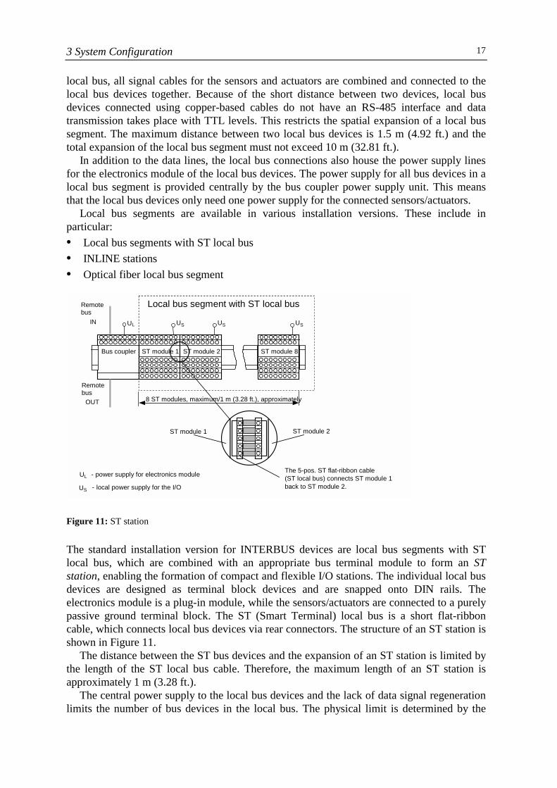
Local bus segments are available in various installation versions. These include inparticular:• Local bus segments with ST local bus• INLINE stations• Optical fiber local bus segment
Figure 11: ST station
The standard installation version for INTERBUS devices are local bus segments with STlocal bus, which are combined with an appropriate bus terminal module to form an STstation, enabling the formation of compact and flexible I/O stations. The individual local busdevices are designed as terminal block devices and are snapped onto DIN rails. Theelectronics module is a plug-in module, while the sensors/actuators are connected to a purelypassive ground terminal block. The ST (Smart Terminal) local bus is a short flat-ribboncable, which connects local bus devices via rear connectors. The structure of an ST station isshown in Figure 11.
The distance between the ST bus devices and the expansion of an ST station is limited bythe length of the ST local bus cable. Therefore, the maximum length of an ST station isapproximately 1 m (3.28 ft.).
The central power supply to the local bus devices and the lack of data signal regenerationlimits the number of bus devices in the local bus. The physical limit is determined by the
Bus coupler
Remote bus
IN
Remote bus
OUT
U L - power supply for electronics module - local power supply for the I/O U S
U L U S
Local bus segment with ST local bus
ST module 1
U S
ST module 2
US
ST module 8
8 ST modules, maximum/1 m (3.28 ft.), approximately
ST module 1 ST module 2
The 5-pos. ST flat-ribbon cable (ST local bus) connects ST module 1 back to ST module 2.
3 System Configuration18
maximum current that can be supplied by the bus coupler power supply unit. The masterfirmware also imposes a logical limit. Currently, a maximum of 8 local bus devices aresupported for SL and ST local buses.
The power supply for the I/O (sensors and actuators) is provided locally via externalconnections.
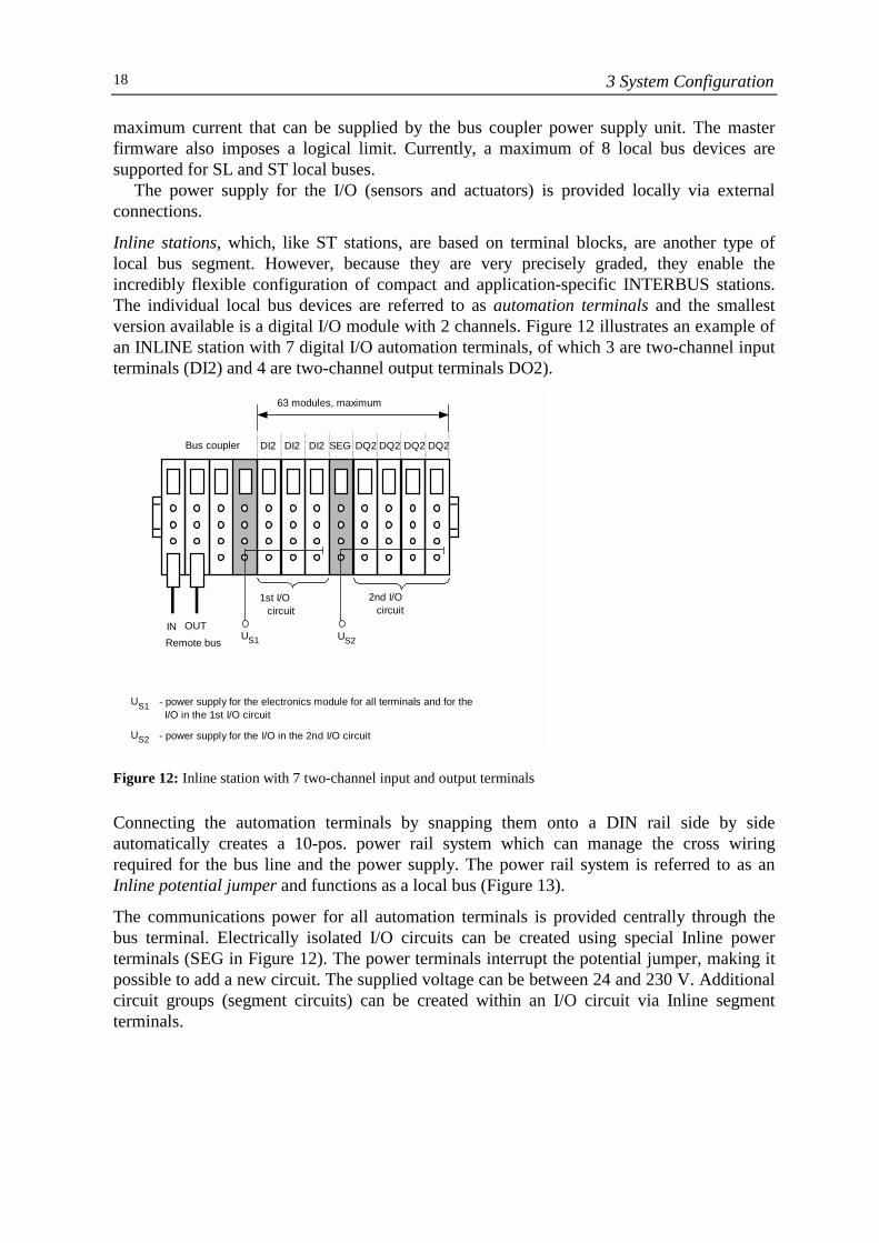
Inline stations, which, like ST stations, are based on terminal blocks, are another type oflocal bus segment. However, because they are very precisely graded, they enable theincredibly flexible configuration of compact and application-specific INTERBUS stations.The individual local bus devices are referred to as automation terminals and the smallestversion available is a digital I/O module with 2 channels. Figure 12 illustrates an example ofan INLINE station with 7 digital I/O automation terminals, of which 3 are two-channel inputterminals (DI2) and 4 are two-channel output terminals DO2).
Figure 12: Inline station with 7 two-channel input and output terminals
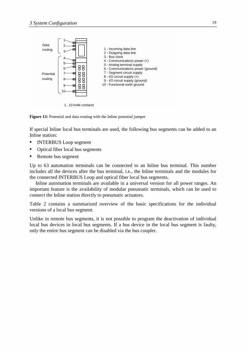
Connecting the automation terminals by snapping them onto a DIN rail side by sideautomatically creates a 10-pos. power rail system which can manage the cross wiringrequired for the bus line and the power supply. The power rail system is referred to as anInline potential jumper and functions as a local bus (Figure 13).
The communications power for all automation terminals is provided centrally through thebus terminal. Electrically isolated I/O circuits can be created using special Inline powerterminals (SEG in Figure 12). The power terminals interrupt the potential jumper, making itpossible to add a new circuit. The supplied voltage can be between 24 and 230 V. Additionalcircuit groups (segment circuits) can be created within an I/O circuit via Inline segmentterminals.
US1 - power supply for the electronics module for all terminals and for the I/O in the 1st I/O circuit
US2 - power supply for the I/O in the 2nd I/O circuit
Bus coupler DI2 DI2 DI2 SEG DQ2 DQ2 DQ2 DQ2
63 modules, maximum
1st I/Ocircuit
2nd I/Ocircuit
US1 US2Remote busIN OUT
3 System Configuration 19
Figure 13: Potential and data routing with the Inline potential jumper
If special Inline local bus terminals are used, the following bus segments can be added to anInline station:• INTERBUS Loop segment• Optical fiber local bus segments• Remote bus segment
Up to 63 automation terminals can be connected to an Inline bus terminal. This numberincludes all the devices after the bus terminal, i.e., the Inline terminals and the modules forthe connected INTERBUS Loop and optical fiber local bus segments.
Inline automation terminals are available in a universal version for all power ranges. Animportant feature is the availability of modular pneumatic terminals, which can be used toconnect the Inline station directly to pneumatic actuators.
Table 2 contains a summarized overview of the basic specifications for the individualversions of a local bus segment.
Unlike in remote bus segments, it is not possible to program the deactivation of individuallocal bus devices in local bus segments. If a bus device in the local bus segment is faulty,only the entire bus segment can be disabled via the bus coupler.
Data
routing
Potential routing
1 - Incoming data line 2 - Outgoing data line 3 - Bus clock 4 - Communications power (+) 5 - Analog terminal supply 6 - Communications power (ground) 7 - Segment circuit supply 8 - I/O circuit supply (+) 9 - I/O circuit supply (ground) 10 - Functional earth ground
1...10 knife contacts
1 2 3 4 5 6 7 8 9
10
3 System Configuration20
Table 2: Basic specifications for local bus segments
Local BusSegment With STLocal Bus
Inline Station Optical FiberLocal BusSegment
Maximum number ofdevices
8 63 63
Maximum distancebetween devices
Mounted side byside
Mounted side byside
5 m (16.40 ft.)
Maximum overallsystem expansion
1 m (3.28 ft.),approximately
4 m (13.12 ft.),approximately
25 m (82.02 ft.)
Device power supply Central via buscoupler
Central via buscoupler
Local
Bus connection ST flat-ribboncable
Inline potentialjumper
2-wire polymeroptical fiber
INTERBUS Loop Segment
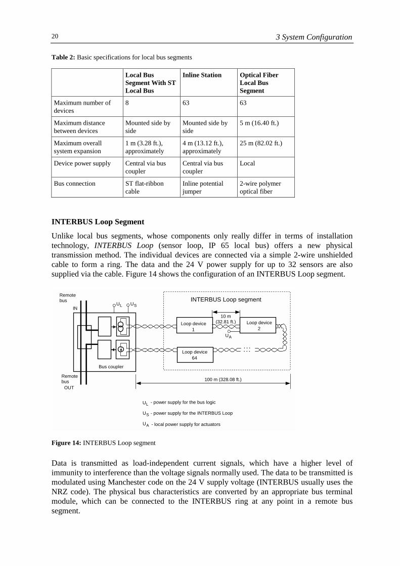
Unlike local bus segments, whose components only really differ in terms of installationtechnology, INTERBUS Loop (sensor loop, IP 65 local bus) offers a new physicaltransmission method. The individual devices are connected via a simple 2-wire unshieldedcable to form a ring. The data and the 24 V power supply for up to 32 sensors are alsosupplied via the cable. Figure 14 shows the configuration of an INTERBUS Loop segment.
Figure 14: INTERBUS Loop segment
Data is transmitted as load-independent current signals, which have a higher level ofimmunity to interference than the voltage signals normally used. The data to be transmitted ismodulated using Manchester code on the 24 V supply voltage (INTERBUS usually uses theNRZ code). The physical bus characteristics are converted by an appropriate bus terminalmodule, which can be connected to the INTERBUS ring at any point in a remote bussegment.
UL
UL U S U A
- power supply for the bus logic
- power supply for the INTERBUS Loop
- local power supply for actuators
Loop device1
Loop device 2
Loop device 64
INTERBUS Loop segment Remote bus
IN
Remote bus
OUT
Bus coupler
. . . . . .
10 m (32.81 ft.)
UA
U S
100 m (328.08 ft.)
3 System Configuration 21
INTERBUS Loop has the following characteristic features:
Expansion: 100 m (328.08 ft.), maximumDistance between two devices: 10 m (32.81 ft.), maximumNumber of devices: 32, maximumCurrent consumption of devices: 1.5 A, maximumConnection medium: Unshielded two-wire cable, 2 x 1.5 mm² (16
AWG)
One of the main fields of application of INTERBUS Loop is the connection of individualdevices with IP 65 and IP 54 connection directly in the system. An extensive range offunctions and devices are available as bus devices.
The INTERBUS protocol is not converted in any way in INTERBUS Loop, which meansthat complex gateways are not required and an INTERBUS Loop segment can be used inconjunction with any other type of INTERBUS device. Data scanning is absolutelysynchronous in all parts of the INTERBUS system. Despite this, the high scanning speed ismaintained.
3.3 Network Configuration
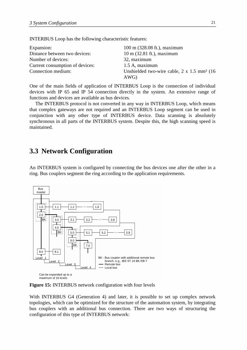
An INTERBUS system is configured by connecting the bus devices one after the other in aring. Bus couplers segment the ring according to the application requirements.
Figure 15: INTERBUS network configuration with four levels
With INTERBUS G4 (Generation 4) and later, it is possible to set up complex networktopologies, which can be optimized for the structure of the automation system, by integratingbus couplers with an additional bus connection. There are two ways of structuring theconfiguration of this type of INTERBUS network:
BK
BK - Bus coupler with additional remote bus branch, e.g., IBS ST 24 BK RB-T
Remote busLocal bus
Busmaster
Level 1Level 2
8.1
BK
1.0
2.0
8.0
1.1 1.2
3.1
BK
5.0
6.0
Level 3
3.2
... 1.8
... 3.8
5.1
7.0
Level 4
5.2 ... 5.8
Can be expanded up to amaximum of 16 levels
3.0
4.0
3 System Configuration22
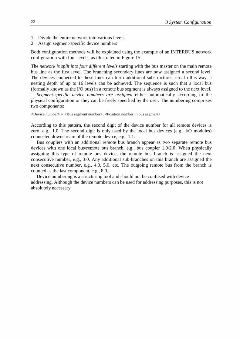
1. Divide the entire network into various levels2. Assign segment-specific device numbers
Both configuration methods will be explained using the example of an INTERBUS networkconfiguration with four levels, as illustrated in Figure 15.
The network is split into four different levels starting with the bus master on the main remotebus line as the first level. The branching secondary lines are now assigned a second level.The devices connected to these lines can form additional substructures, etc. In this way, anesting depth of up to 16 levels can be achieved. The sequence is such that a local bus(formally known as the I/O bus) in a remote bus segment is always assigned to the next level.
Segment-specific device numbers are assigned either automatically according to thephysical configuration or they can be freely specified by the user. The numbering comprisestwo components:<Device number> = <Bus segment number>. <Position number in bus segment>
According to this pattern, the second digit of the device number for all remote devices iszero, e.g., 1.0. The second digit is only used by the local bus devices (e.g., I/O modules)connected downstream of the remote device, e.g., 1.1.
Bus couplers with an additional remote bus branch appear as two separate remote busdevices with one local bus/remote bus branch, e.g., bus coupler 1.0/2.0. When physicallyassigning this type of remote bus device, the remote bus branch is assigned the nextconsecutive number, e.g., 3.0. Any additional sub-branches on this branch are assigned thenext consecutive number, e.g., 4.0, 5.0, etc. The outgoing remote bus from the branch iscounted as the last component, e.g., 8.0.
Device numbering is a structuring tool and should not be confused with deviceaddressing. Although the device numbers can be used for addressing purposes, this is notabsolutely necessary.
4 Data Transmission 23
4 Data Transmission
4.1 Protocol Structure
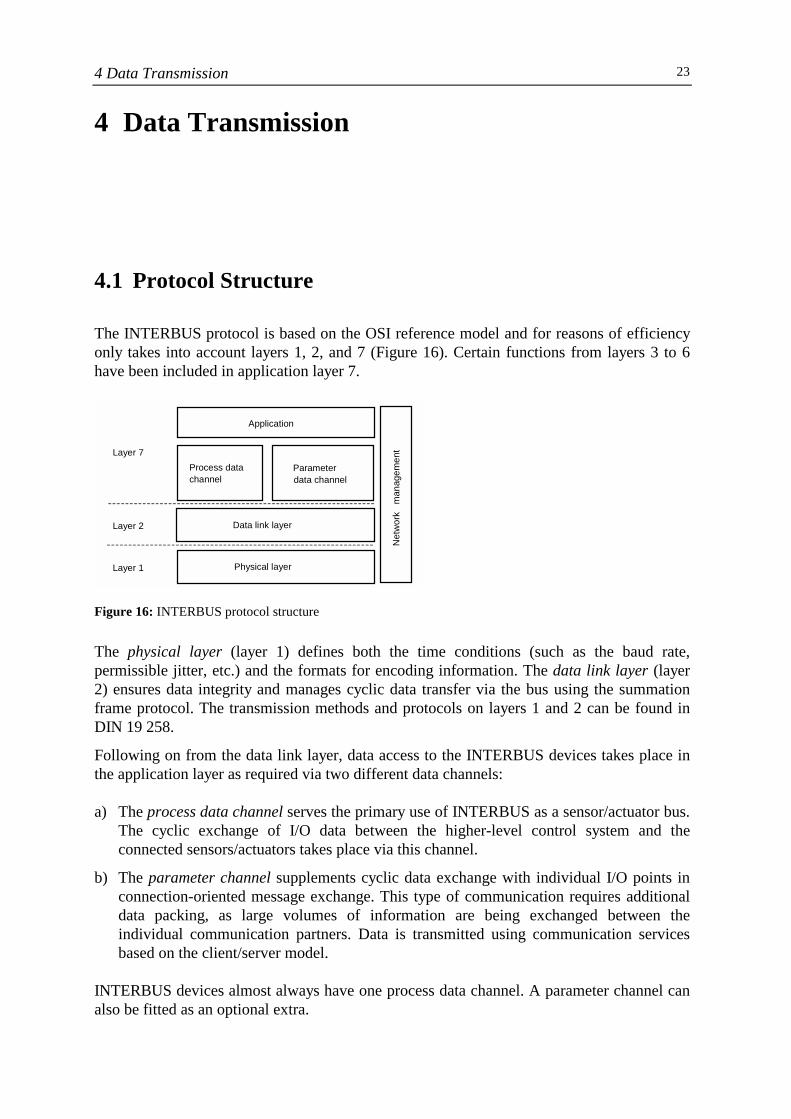
The INTERBUS protocol is based on the OSI reference model and for reasons of efficiencyonly takes into account layers 1, 2, and 7 (Figure 16). Certain functions from layers 3 to 6have been included in application layer 7.
Figure 16: INTERBUS protocol structure
The physical layer (layer 1) defines both the time conditions (such as the baud rate,permissible jitter, etc.) and the formats for encoding information. The data link layer (layer2) ensures data integrity and manages cyclic data transfer via the bus using the summationframe protocol. The transmission methods and protocols on layers 1 and 2 can be found inDIN 19 258.
Following on from the data link layer, data access to the INTERBUS devices takes place inthe application layer as required via two different data channels:
a) The process data channel serves the primary use of INTERBUS as a sensor/actuator bus.The cyclic exchange of I/O data between the higher-level control system and theconnected sensors/actuators takes place via this channel.
b) The parameter channel supplements cyclic data exchange with individual I/O points inconnection-oriented message exchange. This type of communication requires additionaldata packing, as large volumes of information are being exchanged between theindividual communication partners. Data is transmitted using communication servicesbased on the client/server model.
INTERBUS devices almost always have one process data channel. A parameter channel canalso be fitted as an optional extra.
N
etw
ork
man
agem
ent
Application
Process data channel
Parameterdata channel
Data link layer
Physical layer
Layer 7
Layer 2
Layer 1
4 Data Transmission24
During operation, an INTERBUS system requires settings to be made and provides a widerange of diagnostic information. This information is processed by the network managementon each layer. More detailed information about readiness for operation, error states, andstatistical data can also be accessed and evaluated, and network configuration settings can bemade.
The hybrid protocol structure of INTERBUS for the two different data classes (process dataand parameter data) and its independent data transmission via two channels is a decisivefactor in the performance of the INTERBUS protocol. The protocol enables the creation of aseamless network comprising control systems and intelligent field devices right down toindividual sensors and actuators.
The following sections describe in more detail how the individual protocol componentswork.
4.2 Bit Transmission
In layer 1, bits are transmitted at a standard data transmission rate of 500 kbps according tothe NRZ (non-return to zero) method. The data line is scanned in the INTERBUS devices 16times faster, in order to maximize the permissible differences in runtime between the risingand falling edges of a bit within a telegram.
If a two-wire INTERBUS cable is used as standard, a clock signal is not transmitted.A 16 MHz clock generator, which provides the internal 500 kHz clock pulse, operates ineach device. The device clocks are synchronized internally by a common synchronizationmarker in the active INTERBUS telegrams.
Data is transmitted on INTERBUS in the form of encoded data bytes. The completesummation frame protocol is split into 8-bit portions and transmitted between twoINTERBUS devices in telegrams, the format of which is similar to UART.
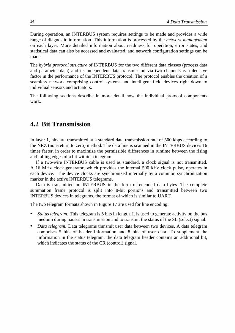
The two telegram formats shown in Figure 17 are used for line encoding:
• Status telegram: This telegram is 5 bits in length. It is used to generate activity on the busmedium during pauses in transmission and to transmit the status of the SL (select) signal.
• Data telegram: Data telegrams transmit user data between two devices. A data telegramcomprises 5 bits of header information and 8 bits of user data. To supplement theinformation in the status telegram, the data telegram header contains an additional bit,which indicates the status of the CR (control) signal.
4 Data Transmission 25
Figure 17: Line encoding in the Physical Layer
Active telegrams are processed in the INTERBUS devices using protocol logic and variousshift registers.
4.3 Summation Frame Protocol
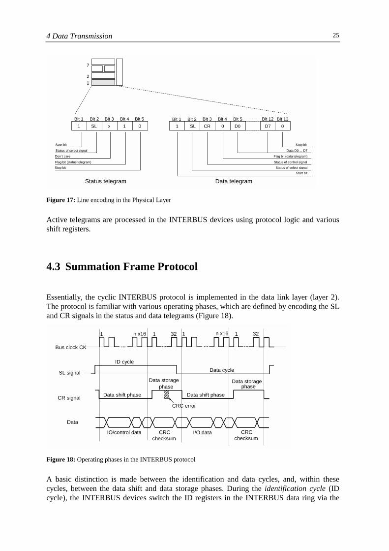
Essentially, the cyclic INTERBUS protocol is implemented in the data link layer (layer 2).The protocol is familiar with various operating phases, which are defined by encoding the SLand CR signals in the status and data telegrams (Figure 18).
Figure 18: Operating phases in the INTERBUS protocol
A basic distinction is made between the identification and data cycles, and, within thesecycles, between the data shift and data storage phases. During the identification cycle (IDcycle), the INTERBUS devices switch the ID registers in the INTERBUS data ring via the
1 2
7
1 SL x 1 0 Bit 1 Bit 2 Bit 3 Bit 4 Bit 5
1 SL CR 0 D0 D7 0 Bit 1 Bit 2 Bit 3 Bit 4 Bit 5 Bit 12 Bit 13
Start bit Status of select signal Don`t care Flag bit (status telegram) Stop bit
Stop bit Data D0 ... D7
Flag bit (data telegram) Status of control signal Status of select signal
Start bit Data telegram Status telegram
Bus clock CK
SL signal
CR signal
Data
... ... ......
ID cycle Data cycle
1 n x16 1 32 1 n x16 1 32
Data shift phase Data shift phase
Data storagephase
CRC error
Data storagephase
IO/control data CRC checksum
I/O data CRC checksum
4 Data Transmission26
protocol control and the bus master can identify all the devices. In the data cycle, the mastersets the SL signal to 0 and the INTERBUS ring is then closed via the data shift register. Interms of the protocol sequence, there is no difference between the data cycle and the IDcycle. The two cycle types only differ in the status of the SL signal and the number and typeof data/registers from which the data is being transmitted. The user data is transmitted in therelevant cycle in the data shift phase (CR signal = 0).
Once the user data has been transmitted, the CR signal switches the system to the datastorage phase or FCS (Frame Check Sequence) phase. In this operating phase, data is savedusing a checksum method with a CRC polynomial according to CCITT.
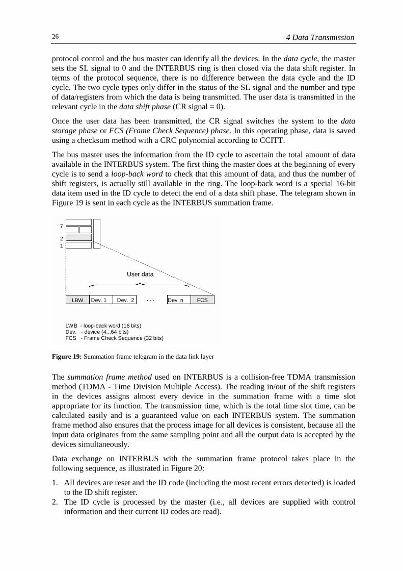
The bus master uses the information from the ID cycle to ascertain the total amount of dataavailable in the INTERBUS system. The first thing the master does at the beginning of everycycle is to send a loop-back word to check that this amount of data, and thus the number ofshift registers, is actually still available in the ring. The loop-back word is a special 16-bitdata item used in the ID cycle to detect the end of a data shift phase. The telegram shown inFigure 19 is sent in each cycle as the INTERBUS summation frame.
Figure 19: Summation frame telegram in the data link layer
The summation frame method used on INTERBUS is a collision-free TDMA transmissionmethod (TDMA - Time Division Multiple Access). The reading in/out of the shift registersin the devices assigns almost every device in the summation frame with a time slotappropriate for its function. The transmission time, which is the total time slot time, can becalculated easily and is a guaranteed value on each INTERBUS system. The summationframe method also ensures that the process image for all devices is consistent, because all theinput data originates from the same sampling point and all the output data is accepted by thedevices simultaneously.
Data exchange on INTERBUS with the summation frame protocol takes place in thefollowing sequence, as illustrated in Figure 20:
1. All devices are reset and the ID code (including the most recent errors detected) is loadedto the ID shift register.
2. The ID cycle is processed by the master (i.e., all devices are supplied with controlinformation and their current ID codes are read).
12
7
LBW Dev. 1 Dev. 2 Dev. n FCS
User data
. . .
LWB - loop-back word (16 bits)Dev. - device (4...64 bits)FCS - Frame Check Sequence (32 bits)
4 Data Transmission 27
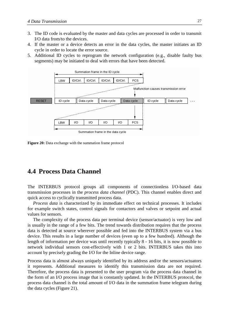
3. The ID code is evaluated by the master and data cycles are processed in order to transmitI/O data from/to the devices.
4. If the master or a device detects an error in the data cycles, the master initiates an IDcycle in order to locate the error source.
5. Additional ID cycles to reprogram the network configuration (e.g., disable faulty bussegments) may be initiated to deal with errors that have been detected.
Figure 20: Data exchange with the summation frame protocol
4.4 Process Data Channel
The INTERBUS protocol groups all components of connectionless I/O-based datatransmission processes in the process data channel (PDC). This channel enables direct andquick access to cyclically transmitted process data.
Process data is characterized by its immediate effect on technical processes. It includesfor example switch states, control signals for contactors and valves or setpoint and actualvalues for sensors.
The complexity of the process data per terminal device (sensor/actuator) is very low andis usually in the range of a few bits. The trend towards distribution requires that the processdata is detected at source wherever possible and fed into the INTERBUS system via a busdevice. This results in a large number of devices (even up to a few hundred). Although thelength of information per device was until recently typically 8 - 16 bits, it is now possible tonetwork individual sensors cost-effectively with 1 or 2 bits. INTERBUS takes this intoaccount by precisely grading the I/O for the Inline device range.
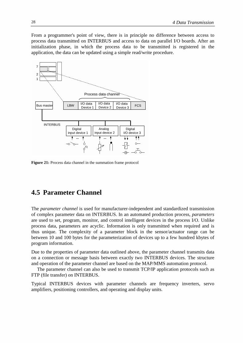
Process data is almost always uniquely identified by its address and/or the sensors/actuatorsit represents. Additional measures to identify this transmission data are not required.Therefore, the process data is presented to the user program via the process data channel inthe form of an I/O process image that is constantly updated. In the INTERBUS protocol, theprocess data channel is the total amount of I/O data in the summation frame telegram duringthe data cycles (Figure 21).
LBW ID/Ctrl. ID/Ctrl.
. . .
ID/Ctrl. ID/Ctrl. FCS
LBW I/O I/O I/O I/O FCS
Data cycle Data cycleData cycle Data cycleID cycle ID cycle
Summation frame in the data cycle
Summation frame in the ID cycle
Malfunction causes transmission error
RESET
4 Data Transmission28
From a programmer's point of view, there is in principle no difference between access toprocess data transmitted on INTERBUS and access to data on parallel I/O boards. After aninitialization phase, in which the process data to be transmitted is registered in theapplication, the data can be updated using a simple read/write procedure.
Figure 21: Process data channel in the summation frame protocol
4.5 Parameter Channel
The parameter channel is used for manufacturer-independent and standardized transmissionof complex parameter data on INTERBUS. In an automated production process, parametersare used to set, program, monitor, and control intelligent devices in the process I/O. Unlikeprocess data, parameters are acyclic. Information is only transmitted when required and isthus unique. The complexity of a parameter block in the sensor/actuator range can bebetween 10 and 100 bytes for the parameterization of devices up to a few hundred kbytes ofprogram information.
Due to the properties of parameter data outlined above, the parameter channel transmits dataon a connection or message basis between exactly two INTERBUS devices. The structureand operation of the parameter channel are based on the MAP/MMS automation protocol.
The parameter channel can also be used to transmit TCP/IP application protocols such asFTP (file transfer) on INTERBUS.
Typical INTERBUS devices with parameter channels are frequency inverters, servoamplifiers, positioning controllers, and operating and display units.
12
7
LBW FCSBus master I/O dataDevice 1
I/O dataDevice 2
I/O dataDevice 3
Digitalinput device 1
Analoginput device 2
DigitalI/O device 3
Process data channel
INTERBUS
... ...
4 Data Transmission 29
Parameter Channel in the Summation Frame Protocol
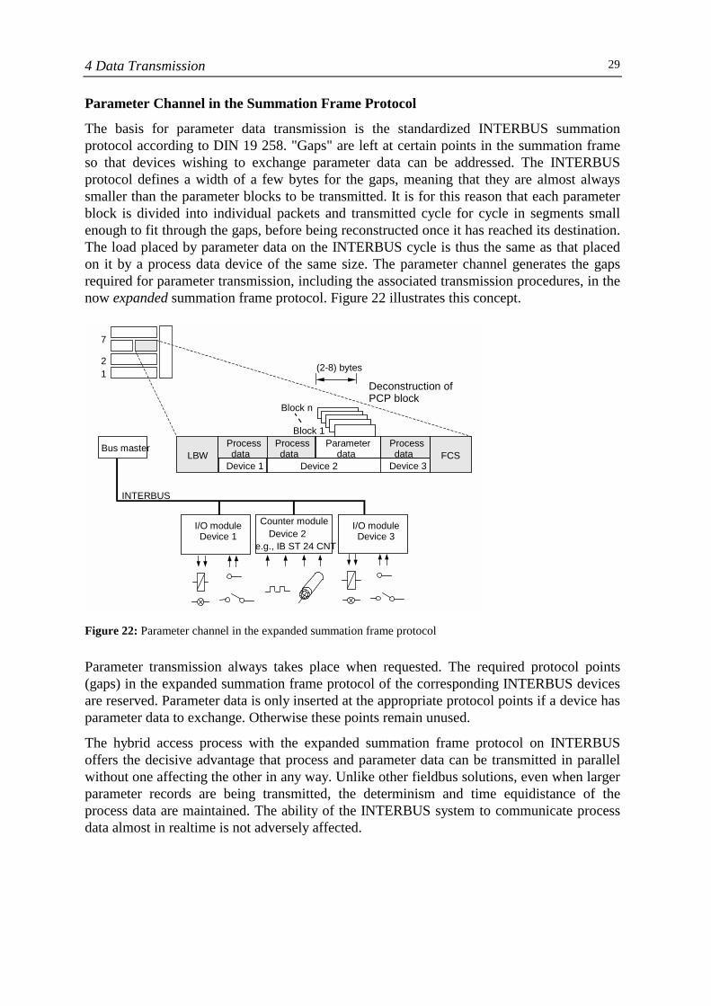
The basis for parameter data transmission is the standardized INTERBUS summationprotocol according to DIN 19 258. "Gaps" are left at certain points in the summation frameso that devices wishing to exchange parameter data can be addressed. The INTERBUSprotocol defines a width of a few bytes for the gaps, meaning that they are almost alwayssmaller than the parameter blocks to be transmitted. It is for this reason that each parameterblock is divided into individual packets and transmitted cycle for cycle in segments smallenough to fit through the gaps, before being reconstructed once it has reached its destination.The load placed by parameter data on the INTERBUS cycle is thus the same as that placedon it by a process data device of the same size. The parameter channel generates the gapsrequired for parameter transmission, including the associated transmission procedures, in thenow expanded summation frame protocol. Figure 22 illustrates this concept.
Figure 22: Parameter channel in the expanded summation frame protocol
Parameter transmission always takes place when requested. The required protocol points(gaps) in the expanded summation frame protocol of the corresponding INTERBUS devicesare reserved. Parameter data is only inserted at the appropriate protocol points if a device hasparameter data to exchange. Otherwise these points remain unused.
The hybrid access process with the expanded summation frame protocol on INTERBUSoffers the decisive advantage that process and parameter data can be transmitted in parallelwithout one affecting the other in any way. Unlike other fieldbus solutions, even when largerparameter records are being transmitted, the determinism and time equidistance of theprocess data are maintained. The ability of the INTERBUS system to communicate processdata almost in realtime is not adversely affected.
1 2
7
LBW FCS Bus master
I/O module Device 1
Counter moduleDevice 2
e.g., IB ST 24 CNT
I/O module Device 3
INTERBUS
Process data
Processdata
Parameter data
Process data
Device 1 Device 2 Device 3
Block n
Block 1
Deconstruction of PCP block
(2-8) bytes
4 Data Transmission30
Method of Operation of the Parameter Channel
Communication on the parameter channel is based on the principle of the client/servermodel.
• A device in a communication relationship initiates communication by sending a request.This device is the client.
• A second communication device receives this request as an indication and responds to it.This device is the server. The request may require a reaction from the server. The serversends this as a response.
• The client receives the response from the server as a confirmation. The communicationprocess is now complete.
INTERBUS' client/server model enables parameter data to be exchanged between the busmaster and INTERBUS devices or between two INTERBUS devices.
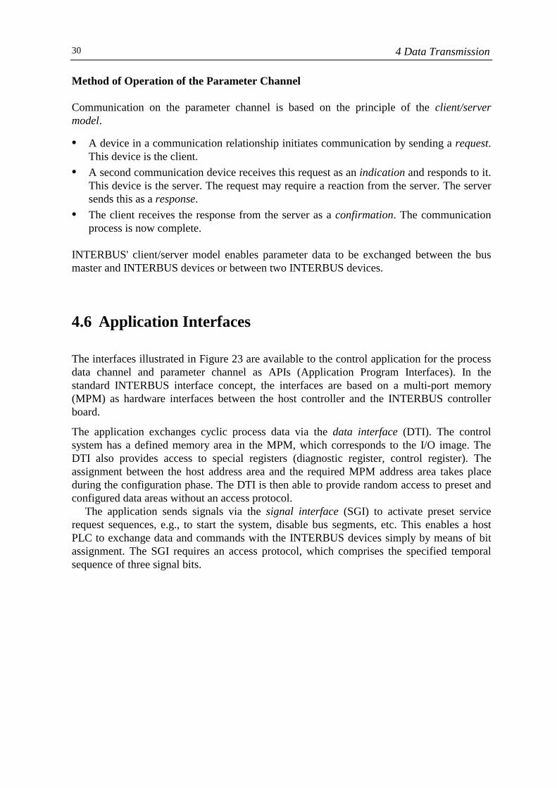
4.6 Application Interfaces
The interfaces illustrated in Figure 23 are available to the control application for the processdata channel and parameter channel as APIs (Application Program Interfaces). In thestandard INTERBUS interface concept, the interfaces are based on a multi-port memory(MPM) as hardware interfaces between the host controller and the INTERBUS controllerboard.
The application exchanges cyclic process data via the data interface (DTI). The controlsystem has a defined memory area in the MPM, which corresponds to the I/O image. TheDTI also provides access to special registers (diagnostic register, control register). Theassignment between the host address area and the required MPM address area takes placeduring the configuration phase. The DTI is then able to provide random access to preset andconfigured data areas without an access protocol.
The application sends signals via the signal interface (SGI) to activate preset servicerequest sequences, e.g., to start the system, disable bus segments, etc. This enables a hostPLC to exchange data and commands with the INTERBUS devices simply by means of bitassignment. The SGI requires an access protocol, which comprises the specified temporalsequence of three signal bits.
4 Data Transmission 31
Figure 23: Application interfaces (API)
The mailbox interface (MXI) must be used if more complex information is to be exchanged.An additional interface, which forwards all information to a protocol controller for
channel-based transmission, may be present below the DTI, SGI, and MXI interfaces. Aprocedure interface (PRI), which enables optimum adaptation to the host operating systemand its programming environment, is usually present above these interfaces.
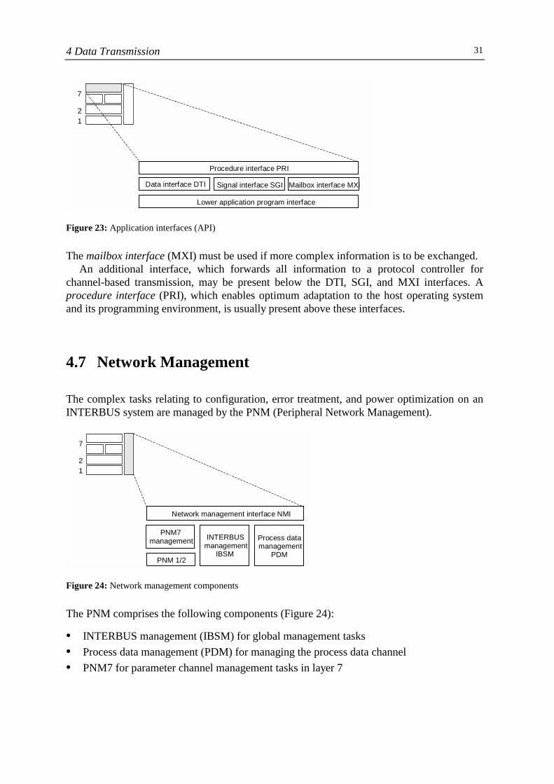
4.7 Network Management
The complex tasks relating to configuration, error treatment, and power optimization on anINTERBUS system are managed by the PNM (Peripheral Network Management).
Figure 24: Network management components
The PNM comprises the following components (Figure 24):
• INTERBUS management (IBSM) for global management tasks• Process data management (PDM) for managing the process data channel• PNM7 for parameter channel management tasks in layer 7
12
7
Procedure interface PRI
Data interface DTI Signal interface SGI Mailbox interface MXI
Lower application program interface
12
7
Network management interface NMI
PNM7management
PNM 1/2
INTERBUSmanagement
IBSM
Process datamanagement
PDM
4 Data Transmission32
The INTERBUS management IBSM manages all tasks relating to operation, configuration,error detection and messaging, statistics, and safety on the entire INTERBUS system. Adistinction is not made between the process data and parameter channels.
Only a small number of IBSM services are generally needed to operate an INTERBUSsystem.
An INTERBUS system can be started up in just three steps:
Step 1: Clear-Display - All error displays are deleted from the masterboard.
Step 2: Configure-Bus - The bus is reconfigured by the master.Step 3: Start-Bus-Cycle - The data cycles are started.
The application interface is provided by the network management interface (NMI). This canbe accessed via the API as illustrated in Figure 23.
5 Electrical Configuration 33
5 Electrical Configuration
5.1 Protocol Chip
The most important element in the electrical configuration of an INTERBUS device is theINTERBUS protocol chip, which manages the complete summation frame protocol andprovides the physical interface to the INTERBUS ring. The bus master and INTERBUSslave devices use different protocol chips according to their function in the INTERBUSsystem. Hardware solutions tailored to meet specific technical requirements are available forboth INTERBUS master and slave solutions.
Protocol Chips for INTERBUS Slaves
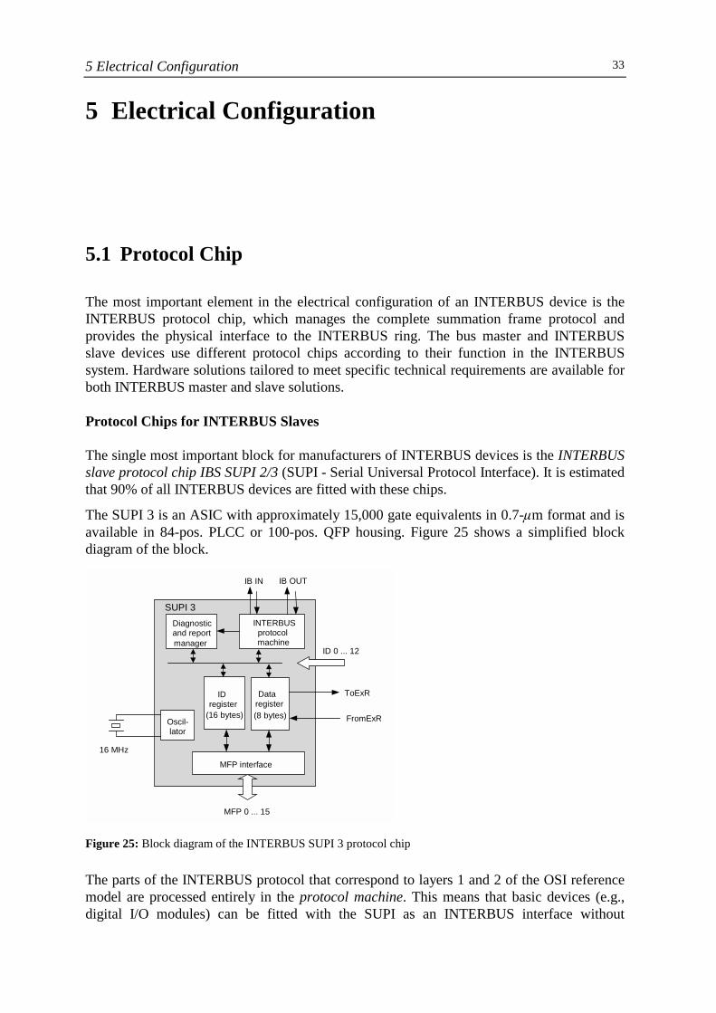
The single most important block for manufacturers of INTERBUS devices is the INTERBUSslave protocol chip IBS SUPI 2/3 (SUPI - Serial Universal Protocol Interface). It is estimatedthat 90% of all INTERBUS devices are fitted with these chips.
The SUPI 3 is an ASIC with approximately 15,000 gate equivalents in 0.7-✙m format and isavailable in 84-pos. PLCC or 100-pos. QFP housing. Figure 25 shows a simplified blockdiagram of the block.
Figure 25: Block diagram of the INTERBUS SUPI 3 protocol chip
The parts of the INTERBUS protocol that correspond to layers 1 and 2 of the OSI referencemodel are processed entirely in the protocol machine. This means that basic devices (e.g.,digital I/O modules) can be fitted with the SUPI as an INTERBUS interface without
ID register
(16 bytes)
Data register (8 bytes)
MFP interface
MFP 0 ... 15
Oscil- lator
16 MHz
INTERBUS protocolmachine
Diagnostic and report manager
SUPI 3
ID 0 ... 12
ToExR
FromExR
IB IN IB OUT
5 Electrical Configuration34
additional software or processing power being required. The protocol machine also providesphysical access to the incoming (IB IN) and outgoing (IB OUT) INTERBUS interface.
Both shift registers - the ID register and data register - operate as send and receivebuffers in the ID and data cycle. The application and/or higher protocol layers can access thisbuffer via the MPM interface (MPM - Multi-Function Pin). The MFP interface can be setaccording to interface requirements.
The data registers can be expanded with external registers (ToExR, FromExR). TheINTERBUS register chip SRE 1, which, if required, can expand the shift register width of anINTERBUS device to 64 bytes, is used for register expansion. By default, the register widthof the SUPI 3 is 8 bytes.
The diagnostic and report manager constantly monitors the operation of the SUPI (on-chip diagnostics). Any error descriptions that are received, such as CRC errors, transient lossof medium, voltage dips, etc., are saved to the ID send buffer and can be read from there bythe master at any time. This means that unique error locations can even be identified forsporadic errors that are difficult to diagnose.
Using the SUPI as the INTERBUS slave chip enables all INTERBUS device variants for theremote and local bus to be implemented, with the exception of those for INTERBUS Loop.INTERBUS Loop also works with the INTERBUS protocol but uses a different physicaltransmission medium, which requires the protocol chip on the physical interface to be of thesame format.
Protocol Chips for INTERBUS Masters
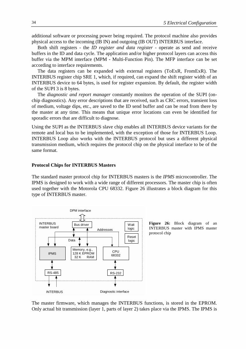
The standard master protocol chip for INTERBUS masters is the IPMS microcontroller. TheIPMS is designed to work with a wide range of different processors. The master chip is oftenused together with the Motorola CPU 68332. Figure 26 illustrates a block diagram for thistype of INTERBUS master.
Figure 26: Block diagram of anINTERBUS master with IPMS masterprotocol chip
The master firmware, which manages the INTERBUS functions, is stored in the EPROM.Only actual bit transmission (layer 1, parts of layer 2) takes place via the IPMS. The IPMS is
DPM interface
Bus driverINTERBUSmaster board
Waitlogic
Resetlogic
Addresses
Data
IPMSMemory, e.g.,128 K EPROM 32 K RAM
CPU68332
RS-485 RS-232
INTERBUS Diagnostic interface
5 Electrical Configuration 35
connected to the relevant host system via a shared memory area, which, in its simplestformat, is a DPM (Dual Port Memory) or an MPM (Multi-Port Memory).
INTERBUS masters with IPMS are available in various formats depending on thefunctions required.
5.2 Local Bus Devices
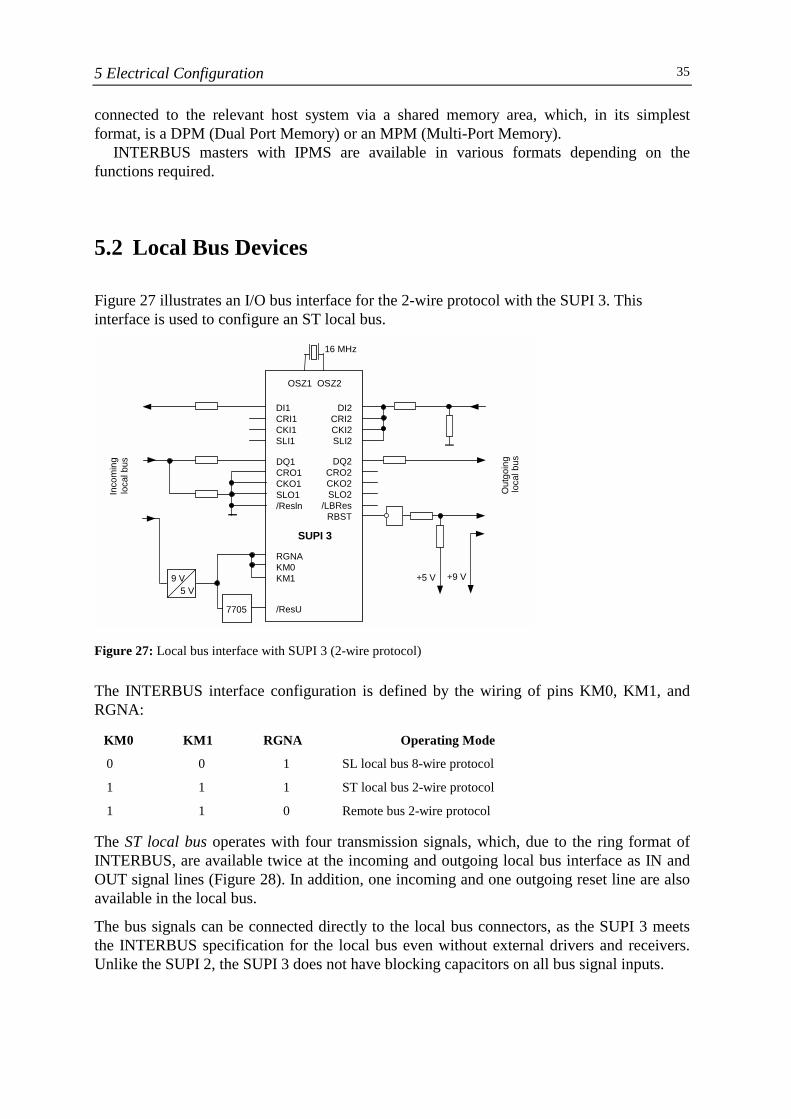
Figure 27 illustrates an I/O bus interface for the 2-wire protocol with the SUPI 3. Thisinterface is used to configure an ST local bus.
Figure 27: Local bus interface with SUPI 3 (2-wire protocol)
The INTERBUS interface configuration is defined by the wiring of pins KM0, KM1, andRGNA:
KM0 KM1 RGNA Operating Mode
0 0 1 SL local bus 8-wire protocol
1 1 1 ST local bus 2-wire protocol
1 1 0 Remote bus 2-wire protocol
The ST local bus operates with four transmission signals, which, due to the ring format ofINTERBUS, are available twice at the incoming and outgoing local bus interface as IN andOUT signal lines (Figure 28). In addition, one incoming and one outgoing reset line are alsoavailable in the local bus.
The bus signals can be connected directly to the local bus connectors, as the SUPI 3 meetsthe INTERBUS specification for the local bus even without external drivers and receivers.Unlike the SUPI 2, the SUPI 3 does not have blocking capacitors on all bus signal inputs.
16 MHz
OSZ1 OSZ2
DI1 CRI1 CKI1SLI1
DI2 CRI2 CKI2SLI2
DQ1CRO1 CKO1 SLO1 /Resln
DQ2 CRO2 CKO2 SLO2
/LBRes RBST
SUPI 3 RGNA KM0KM1
/ResU
9 V 5 V
7705
+5 V +9 V
Inco
min
g lo
cal b
us
Out
goin
g lo
cal b
us
5 Electrical Configuration36
Figure 28: Signal routing in the INTERBUS local bus segment (example: data lines)
The 5 V supply for the device logic is drawn from the 9 V bus connector supply. The Type7705 monitoring circuit monitors the 5 V supply and generates the initialization reset.
The remote bus connector closes the INTERBUS ring if the device is the last one in thatlocal bus segment. The remote bus connector signal is jumpered in the output connectorafter +5 V. If the output connector is not present (remote bus connector = 0), the SUPIterminates the signal flow and diverts the outgoing interface to the return path.
The ST local bus is distinguished by the lack of an RS-485 driver and the transmission of theprotocol with TTL levels. A five-wire flat-ribbon cable is used as the bus cable to connectthe modules.
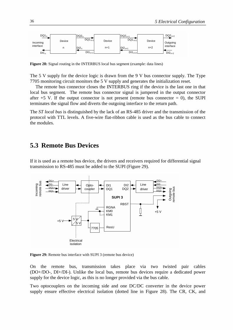
5.3 Remote Bus Devices
If it is used as a remote bus device, the drivers and receivers required for differential signaltransmission to RS-485 must be added to the SUPI (Figure 29).
Figure 29: Remote bus interface with SUPI 3 (remote bus device)
On the remote bus, transmission takes place via two twisted pair cables(DO+/DO-, DI+/DI-). Unlike the local bus, remote bus devices require a dedicated powersupply for the device logic, as this is no longer provided via the bus cable.
Two optocouplers on the incoming side and one DC/DC converter in the device powersupply ensure effective electrical isolation (dotted line in Figure 28). The CR, CK, and
Device
n+1
Device
n
Device
n+2 Outgoinginterface
Incoming interface
DQ2 n+2
DI2 n+2DI1 n+2
DQ1n+2
DI2 n+1
DQ2 n+1
DI1 n+1
DQ1 n+1
DI2 n
DQ2 n
DI1 n
DQ1 n
5 V 5 V
7705
Line driver
Opto-coupler
DI1 DQ1
DI2DQ2
SUPI 3
RGNA KM0 KM1
RBST
ResU
Line driver
Out
goin
g re
mot
e bu
s
Inco
min
g re
mot
e bu
s DI1+ DI1- DQ1+ DQ1-
+5 V
+5 V
DI2+DI2-DQ2+ DQ2-
Electrical isolation
5 Electrical Configuration 37
SL signals are generated on the 2-wire remote bus from the transmission telegram and canthus be connected to ground.
If the SUPI is configured as a bus coupler, in addition to the incoming and outgoing remotebus interfaces, an additional outgoing local bus interface is available via the MFP pins. Thislocal bus interface is wired as illustrated in Figure 27.
5.4 INTERBUS Loop Devices
Although INTERBUS Loop devices also operate with the standardized INTERBUS protocol,they do not transmit voltage signals to RS-485, which is usually the case on INTERBUS.Instead, they use load-independent current signals and Manchester coding to transmit thedata and supply voltage on one and the same bus line (loop).
Due to the different physical transmission medium, a special protocol chip, the IBS LPC, isavailable for INTERBUS Loop. This chip is an ASIC with approximately 7000 gateequivalents and is supplied in QFP-44 housing. Special loop diagnostics are integrated intothe LPC 2 to extend the familiar diagnostic functions of the SUPI 3. To simplify the externalwiring, the chip also contains a 16 MHz quartz oscillator, overtemperature protection, a 5 Vvoltage regulator, and a reset generator with undervoltage monitoring.
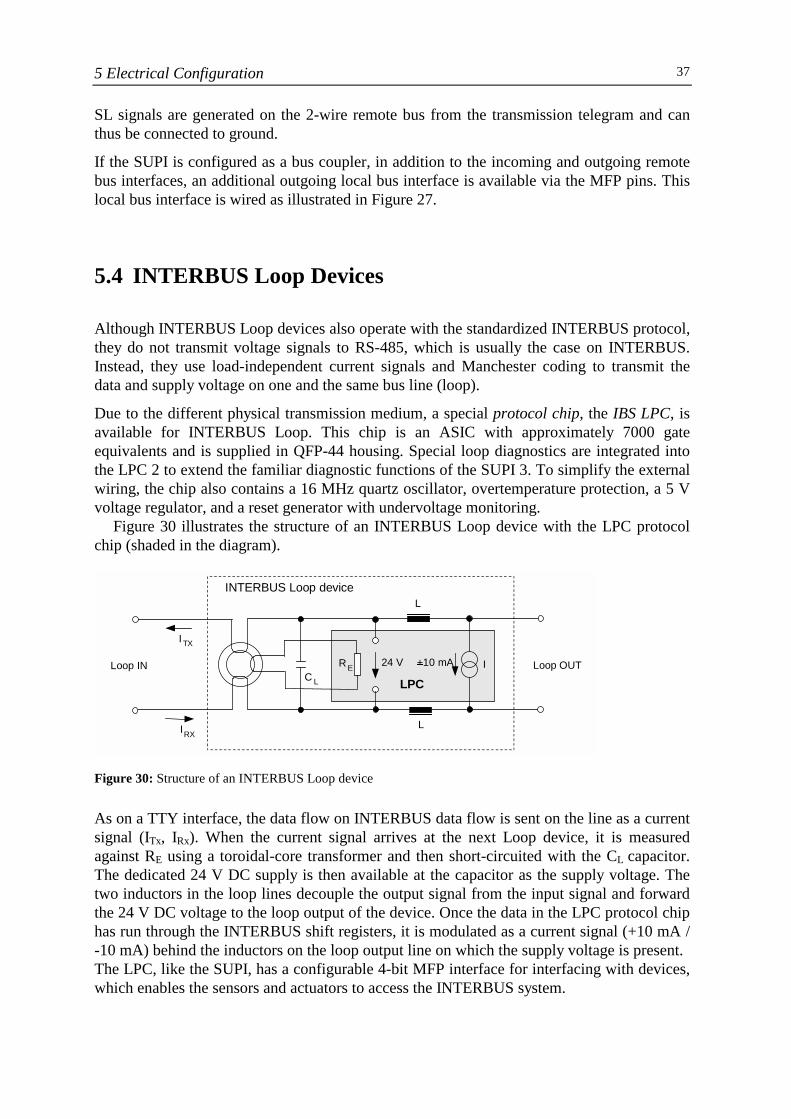
Figure 30 illustrates the structure of an INTERBUS Loop device with the LPC protocolchip (shaded in the diagram).
Figure 30: Structure of an INTERBUS Loop device
As on a TTY interface, the data flow on INTERBUS data flow is sent on the line as a currentsignal (ITx, IRx). When the current signal arrives at the next Loop device, it is measuredagainst RE using a toroidal-core transformer and then short-circuited with the CL capacitor.The dedicated 24 V DC supply is then available at the capacitor as the supply voltage. Thetwo inductors in the loop lines decouple the output signal from the input signal and forwardthe 24 V DC voltage to the loop output of the device. Once the data in the LPC protocol chiphas run through the INTERBUS shift registers, it is modulated as a current signal (+10 mA /-10 mA) behind the inductors on the loop output line on which the supply voltage is present.The LPC, like the SUPI, has a configurable 4-bit MFP interface for interfacing with devices,which enables the sensors and actuators to access the INTERBUS system.
INTERBUS Loop device
Loop IN Loop OUT
L
24 V I
ITX
IRX
R EC L LPC
L
+10 mA

5 Electrical Configuration38
A loop bus segment is interfaced with the INTERBUS remote bus using special INTERBUSLoop bus couplers, which also provide the supply voltage for the Loop.
6 System Components 39
6 System Components
The INTERBUS system components for structuring basic INTERBUS systems essentiallycomprise controller boards for open computer systems and controller boards forprogrammable logic controllers.
6.1 Controller Boards for Open Computer Systems
INTERBUS offers various controller boards with graded power ranges for standardized andmanufacturer-independent PC technology and for VMEbus systems. Depending on thecontroller board, both computer systems can operate as INTERBUS bus masters or beintegrated as slave devices into an INTERBUS system.
PC Controller Boards
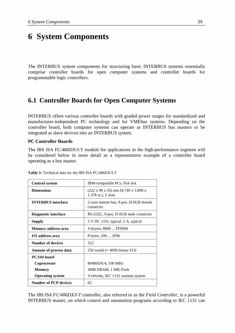
The IBS ISA FC/486DX/I-T module for applications in the high-performance segment willbe considered below in more detail as a representative example of a controller boardoperating as a bus master.
Table 3: Technical data for the IBS ISA FC/486DX/I-T
Control system IBM-compatible PCs, ISA slot
Dimensions (222 x 99 x 35) mm [8.740 x 3.898 x1.378 in.], 2 slots
INTERBUS interface 2-wire remote bus, 9-pos. D-SUB femaleconnector
Diagnostic interface RS-232C, 9-pos. D-SUB male connector
Supply 5 V DC ±5%, typical; 2 A, typical
Memory address area 4 kbytes, 8000 ... FF000h
I/O address area 8 bytes, 100 ... 3F8h
Number of devices 512
Amount of process data 256 words (= 4096 binary I/O)
PC/104 board Coprocessor Memory Operating system
80486DX/4, 100 MHz4MB DRAM, 1 MB FlashVxWorks, IEC 1131 runtime system
Number of PCP devices 62
The IBS ISA FC/486DX/I-T controller, also referred to as the Field Controller, is a powerfulINTERBUS master, on which control and automation programs according to IEC 1131 can
40 6 System Components
run independent of the host PC. The Field Controller uses an embedded PC board accordingto the PC/104 standard as an integrated coprocessor board. PC WORX automation softwareis used with all Field Controllers to provide seamless configuration and programming underIEC 1131. Table 3 contains the general technical data for the IBS ISA FC/486DX/I-T.
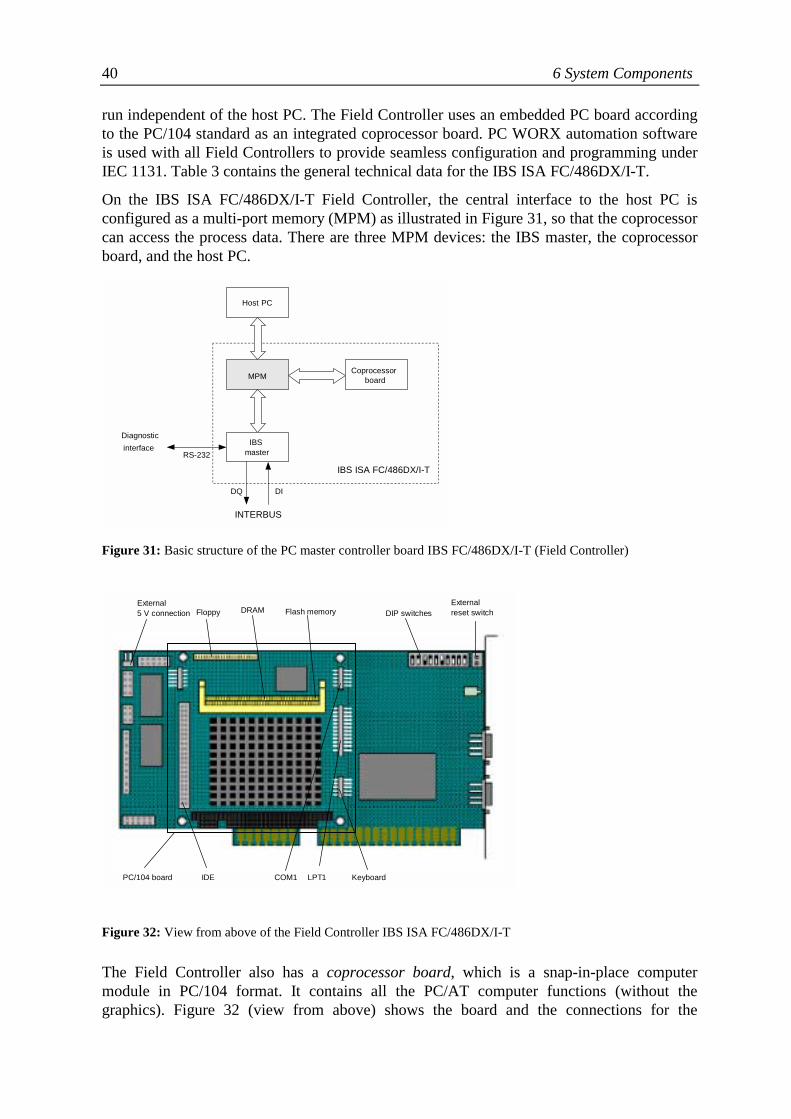
On the IBS ISA FC/486DX/I-T Field Controller, the central interface to the host PC isconfigured as a multi-port memory (MPM) as illustrated in Figure 31, so that the coprocessorcan access the process data. There are three MPM devices: the IBS master, the coprocessorboard, and the host PC.
Figure 31: Basic structure of the PC master controller board IBS FC/486DX/I-T (Field Controller)
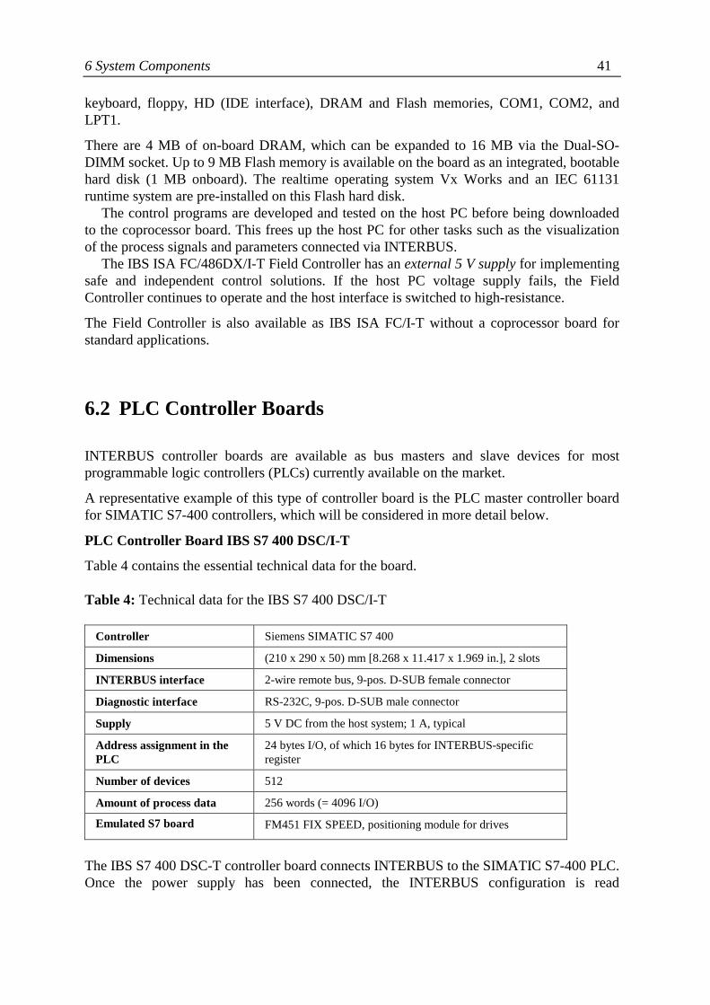
Figure 32: View from above of the Field Controller IBS ISA FC/486DX/I-T
The Field Controller also has a coprocessor board, which is a snap-in-place computermodule in PC/104 format. It contains all the PC/AT computer functions (without thegraphics). Figure 32 (view from above) shows the board and the connections for the
External5 V connection Floppy DRAM Flash memory DIP switches
Externalreset switch
PC/104 board IDE COM1 LPT1 Keyboard
MPM Coprocessorboard
IBS master
Host PC
DIDQ
INTERBUS
Diagnostic interface
RS-232 IBS ISA FC/486DX/I-T
6 System Components 41
keyboard, floppy, HD (IDE interface), DRAM and Flash memories, COM1, COM2, andLPT1.
There are 4 MB of on-board DRAM, which can be expanded to 16 MB via the Dual-SO-DIMM socket. Up to 9 MB Flash memory is available on the board as an integrated, bootablehard disk (1 MB onboard). The realtime operating system Vx Works and an IEC 61131runtime system are pre-installed on this Flash hard disk.
The control programs are developed and tested on the host PC before being downloadedto the coprocessor board. This frees up the host PC for other tasks such as the visualizationof the process signals and parameters connected via INTERBUS.
The IBS ISA FC/486DX/I-T Field Controller has an external 5 V supply for implementingsafe and independent control solutions. If the host PC voltage supply fails, the FieldController continues to operate and the host interface is switched to high-resistance.
The Field Controller is also available as IBS ISA FC/I-T without a coprocessor board forstandard applications.
6.2 PLC Controller Boards
INTERBUS controller boards are available as bus masters and slave devices for mostprogrammable logic controllers (PLCs) currently available on the market.
A representative example of this type of controller board is the PLC master controller boardfor SIMATIC S7-400 controllers, which will be considered in more detail below.
PLC Controller Board IBS S7 400 DSC/I-T
Table 4 contains the essential technical data for the board.
Table 4: Technical data for the IBS S7 400 DSC/I-T
Controller Siemens SIMATIC S7 400
Dimensions (210 x 290 x 50) mm [8.268 x 11.417 x 1.969 in.], 2 slots
INTERBUS interface 2-wire remote bus, 9-pos. D-SUB female connector
Diagnostic interface RS-232C, 9-pos. D-SUB male connector
Supply 5 V DC from the host system; 1 A, typical
Address assignment in thePLC
24 bytes I/O, of which 16 bytes for INTERBUS-specificregister
Number of devices 512
Amount of process data 256 words (= 4096 I/O)
Emulated S7 board FM451 FIX SPEED, positioning module for drives
The IBS S7 400 DSC-T controller board connects INTERBUS to the SIMATIC S7-400 PLC.Once the power supply has been connected, the INTERBUS configuration is read
42 6 System Components
automatically and started with the parameterization stored in the Flash parameterizationmemory. As an INTERBUS master, the board supports the following functions:• Construction of INTERBUS networks with up to 16 levels• Synchronization of PLC program and INTERBUS cycle• Process data preprocessing• Parameterization of alternative and changing INTERBUS segment parts• Comprehensive diagnostics and easy operation
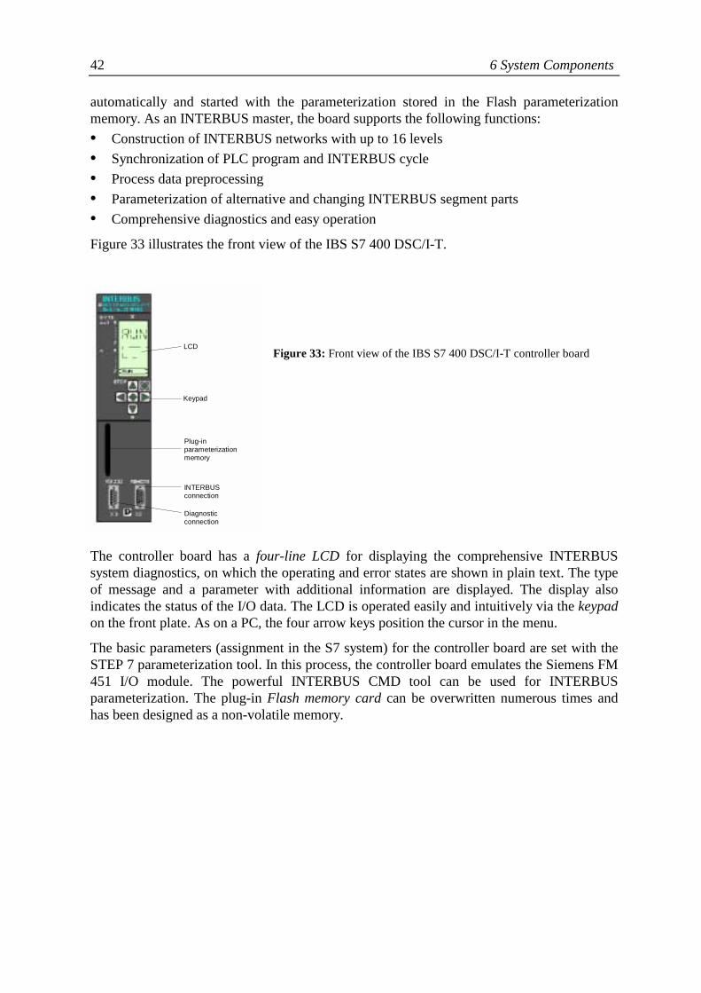
Figure 33 illustrates the front view of the IBS S7 400 DSC/I-T.
Figure 33: Front view of the IBS S7 400 DSC/I-T controller board
The controller board has a four-line LCD for displaying the comprehensive INTERBUSsystem diagnostics, on which the operating and error states are shown in plain text. The typeof message and a parameter with additional information are displayed. The display alsoindicates the status of the I/O data. The LCD is operated easily and intuitively via the keypadon the front plate. As on a PC, the four arrow keys position the cursor in the menu.
The basic parameters (assignment in the S7 system) for the controller board are set with theSTEP 7 parameterization tool. In this process, the controller board emulates the Siemens FM451 I/O module. The powerful INTERBUS CMD tool can be used for INTERBUSparameterization. The plug-in Flash memory card can be overwritten numerous times andhas been designed as a non-volatile memory.
LCD
Keypad
Plug-inparameterizationmemory
INTERBUSconnection
Diagnosticconnection
7 Device Modules 43
7 Device Modules
INTERBUS devices integrated into control cabinets or terminal boxes with IP 20 protectionare referred to as device modules. Essentially, three installation variants are available, whichare described in Table 5.
Table 5: Installation variants with INTERBUS device modules
InstallationVariant
Description INTERBUSInterface
Product Example
Device modulesfor compactstations
Modules with several I/O points (up to 32digital I/O), function modules, can bemounted side by side on DIN rails,exchangeable electronics module,potential routing
Local bus ST family fromPhoenix Contact,WINbloc IPS familyfrom Weidmüller
Automationterminals
I/O modules with 1 … 4 digital I/O,function modules, can be mounted side byside on DIN rails, internal potentialjumper
Local bus INTERBUS Inlinefrom Phoenix Contact,IBS modules fromWAGO's 750 range
Individualmodules
Various compact modules from differentmanufacturers, can be mounted separatelyor on DIN rails, up to 32 digital I/O,special functions
Remote bus RT modules fromPhoenix Contact, RIOstand-alone modulesfrom Schleicher
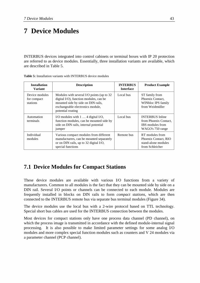
7.1 Device Modules for Compact Stations
These device modules are available with various I/O functions from a variety ofmanufacturers. Common to all modules is the fact that they can be mounted side by side on aDIN rail. Several I/O points or channels can be connected to each module. Modules arefrequently installed in blocks on DIN rails to form compact stations, which are thenconnected to the INTERBUS remote bus via separate bus terminal modules (Figure 34).
The device modules use the local bus with a 2-wire protocol based on TTL technology.Special short bus cables are used for the INTERBUS connection between the modules.
Most devices for compact stations only have one process data channel (PD channel), onwhich the process image is transmitted in accordance with the defined module-internal signalprocessing. It is also possible to make limited parameter settings for some analog I/Omodules and more complex special function modules such as counters and V 24 modules viaa parameter channel (PCP channel).
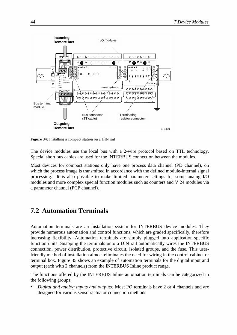
44 7 Device Modules
Figure 34: Installing a compact station on a DIN rail
The device modules use the local bus with a 2-wire protocol based on TTL technology.Special short bus cables are used for the INTERBUS connection between the modules.
Most devices for compact stations only have one process data channel (PD channel), onwhich the process image is transmitted in accordance with the defined module-internal signalprocessing. It is also possible to make limited parameter settings for some analog I/Omodules and more complex special function modules such as counters and V 24 modules viaa parameter channel (PCP channel).
7.2 Automation Terminals
Automation terminals are an installation system for INTERBUS device modules. Theyprovide numerous automation and control functions, which are graded specifically, thereforeincreasing flexibility. Automation terminals are simply plugged into application-specificfunction units. Snapping the terminals onto a DIN rail automatically wires the INTERBUSconnection, power distribution, protective circuit, isolated groups, and the fuse. This user-friendly method of installation almost eliminates the need for wiring in the control cabinet orterminal box. Figure 35 shows an example of automation terminals for the digital input andoutput (each with 2 channels) from the INTERBUS Inline product range.
The functions offered by the INTERBUS Inline automation terminals can be categorized inthe following groups:• Digital and analog inputs and outputs: Most I/O terminals have 2 or 4 channels and are
designed for various sensor/actuator connection methods
IncomingRemote bus
OutgoingRemote bus
Bus terminalmodule
Bus connector(ST cable)
Terminatingresistor connector
I/O modules
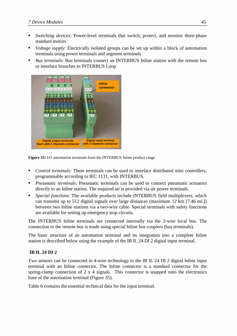
7 Device Modules 45
• Switching devices: Power-level terminals that switch, protect, and monitor three-phasestandard motors
• Voltage supply: Electrically isolated groups can be set up within a block of automationterminals using power terminals and segment terminals
• Bus terminals: Bus terminals connect an INTERBUS Inline station with the remote busor interface branches to INTERBUS Loop
Figure 35: I/O automation terminals from the INTERBUS Inline product range
• Control terminals: These terminals can be used to interface distributed mini controllers,programmable according to IEC 1131, with INTERBUS.
• Pneumatic terminals: Pneumatic terminals can be used to connect pneumatic actuatorsdirectly to an Inline station. The required air is provided via air power terminals.
• Special functions: The available products include INTERBUS field multiplexers, whichcan transmit up to 512 digital signals over large distances (maximum 12 km [7.46 mi.])between two Inline stations via a two-wire cable. Special terminals with safety functionsare available for setting up emergency stop circuits.
The INTERBUS Inline terminals are connected internally via the 2-wire local bus. Theconnection to the remote bus is made using special Inline bus couplers (bus terminals).
The basic structure of an automation terminal and its integration into a complete Inlinestation is described below using the example of the IB IL 24 DI 2 digital input terminal.
IB IL 24 DI 2
Two sensors can be connected in 4-wire technology to the IB IL 24 DI 2 digital Inline inputterminal with an Inline connector. The Inline connector is a standard connector for thespring-clamp connection of 2 x 4 signals. This connector is snapped onto the electronicsbase of the automation terminal (Figure 35).
Table 6 contains the essential technical data for the input terminal.
Inlineconnector
Digital output terminalsEach with 2 channels connector
Digital input terminalwith 2 channels connector
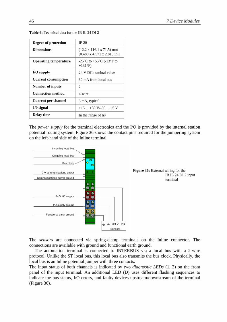
46 7 Device Modules
Table 6: Technical data for the IB IL 24 DI 2
Degree of protection IP 20
Dimensions (12.2 x 116.1 x 71.5) mm[0.480 x 4.571 x 2.815 in.]
Operating temperature -25°C to +55°C (-13°F to+131°F)
I/O supply 24 V DC nominal value
Current consumption 30 mA from local bus
Number of inputs 2
Connection method 4-wire
Current per channel 3 mA, typical
1/0 signal +15 ... +30 V/-30 ... +5 V
Delay time In the range of ✙s
The power supply for the terminal electronics and the I/O is provided by the internal stationpotential routing system. Figure 36 shows the contact pins required for the jumpering systemon the left-hand side of the Inline terminal.
Figure 36: External wiring for the IB IL 24 DI 2 input terminal
The sensors are connected via spring-clamp terminals on the Inline connector. Theconnections are available with ground and functional earth ground.
The automation terminal is connected to INTERBUS via a local bus with a 2-wireprotocol. Unlike the ST local bus, this local bus also transmits the bus clock. Physically, thelocal bus is an Inline potential jumper with three contacts.The input status of both channels is indicated by two diagnostic LEDs (1, 2) on the frontpanel of the input terminal. An additional LED (D) uses different flashing sequences toindicate the bus status, I/O errors, and faulty devices upstream/downstream of the terminal(Figure 36).
Incoming local bus
Outgoing local bus
Bus clock
7 V communications power
Communications power ground
24 V I/O supply
I/O supply ground
Functional earth ground
+24 V IN1
Sensors
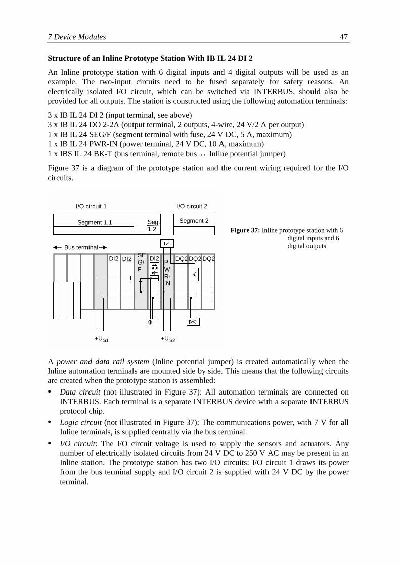
7 Device Modules 47
Structure of an Inline Prototype Station With IB IL 24 DI 2
An Inline prototype station with 6 digital inputs and 4 digital outputs will be used as anexample. The two-input circuits need to be fused separately for safety reasons. Anelectrically isolated I/O circuit, which can be switched via INTERBUS, should also beprovided for all outputs. The station is constructed using the following automation terminals:
3 x IB IL 24 DI 2 (input terminal, see above)3 x IB IL 24 DO 2-2A (output terminal, 2 outputs, 4-wire, 24 V/2 A per output)1 x IB IL 24 SEG/F (segment terminal with fuse, 24 V DC, 5 A, maximum)1 x IB IL 24 PWR-IN (power terminal, 24 V DC, 10 A, maximum)1 x IBS IL 24 BK-T (bus terminal, remote bus ↔ Inline potential jumper)
Figure 37 is a diagram of the prototype station and the current wiring required for the I/Ocircuits.
Figure 37: Inline prototype station with 6digital inputs and 6digital outputs
A power and data rail system (Inline potential jumper) is created automatically when theInline automation terminals are mounted side by side. This means that the following circuitsare created when the prototype station is assembled:• Data circuit (not illustrated in Figure 37): All automation terminals are connected on
INTERBUS. Each terminal is a separate INTERBUS device with a separate INTERBUSprotocol chip.
• Logic circuit (not illustrated in Figure 37): The communications power, with 7 V for allInline terminals, is supplied centrally via the bus terminal.
• I/O circuit: The I/O circuit voltage is used to supply the sensors and actuators. Anynumber of electrically isolated circuits from 24 V DC to 250 V AC may be present in anInline station. The prototype station has two I/O circuits: I/O circuit 1 draws its powerfrom the bus terminal supply and I/O circuit 2 is supplied with 24 V DC by the powerterminal.
I/O circuit 1 I/O circuit 2
Segment 1.1 Segment 2Seg.1.2
Bus terminal
DQ2DI2 DI2 DI2 DQ2 DQ2SEG/F
PWR-IN
.. ...
+US1 +US2
48 7 Device Modules
• Segment circuit: Segment terminals can be used to set up additional circuits within an I/Ocircuit. These segment circuits can be individually fused (segment 1.2 in Figure 37) orswitched off/on (segment 2 in Figure 37) independently from the rest of the station.
Most automation terminals operate with a single process data channel. Terminals with morecomplex functions, e.g., IB IL 400 power terminals, can be parameterized via the parameterchannel.
7.3 Individual Modules
In addition to the two specific INTERBUS installation device groups described above,numerous device modules are available as individual modules. These individual modules areoften characterized by the availability of more complex functions and parameterization viathe parameter channel.
In accordance with the above classification as device modules, all individual modules aresupplied with IP 20 protection. They can be mounted either directly in control cabinets,terminal boxes or similar, or combined with other automation modules and installed as built-in devices in larger device or machine housings.
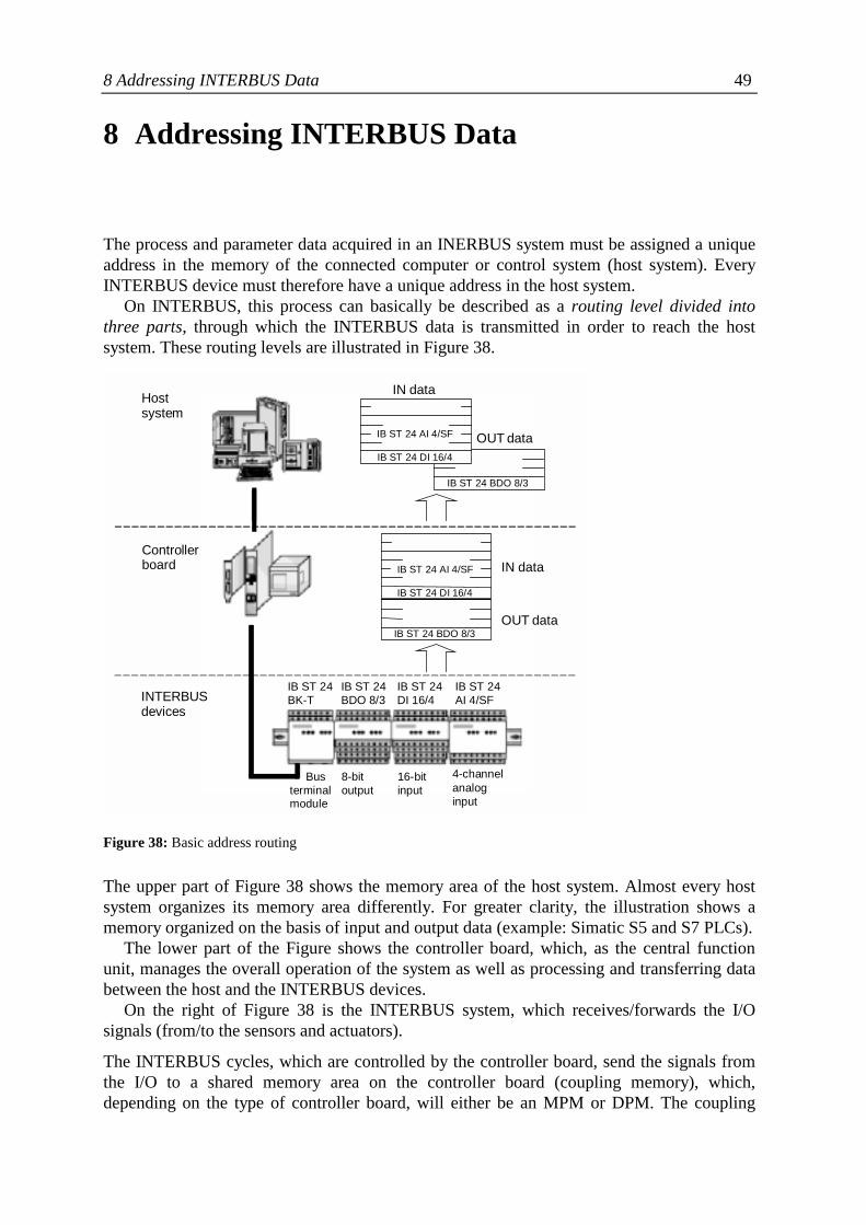
8 Addressing INTERBUS Data 49
8 Addressing INTERBUS Data
The process and parameter data acquired in an INERBUS system must be assigned a uniqueaddress in the memory of the connected computer or control system (host system). EveryINTERBUS device must therefore have a unique address in the host system.
On INTERBUS, this process can basically be described as a routing level divided intothree parts, through which the INTERBUS data is transmitted in order to reach the hostsystem. These routing levels are illustrated in Figure 38.
Figure 38: Basic address routing
The upper part of Figure 38 shows the memory area of the host system. Almost every hostsystem organizes its memory area differently. For greater clarity, the illustration shows amemory organized on the basis of input and output data (example: Simatic S5 and S7 PLCs).
The lower part of the Figure shows the controller board, which, as the central functionunit, manages the overall operation of the system as well as processing and transferring databetween the host and the INTERBUS devices.
On the right of Figure 38 is the INTERBUS system, which receives/forwards the I/Osignals (from/to the sensors and actuators).
The INTERBUS cycles, which are controlled by the controller board, send the signals fromthe I/O to a shared memory area on the controller board (coupling memory), which,depending on the type of controller board, will either be an MPM or DPM. The coupling
Busterminalmodule
8-bitoutput
16-bitinput
4-channelanaloginput
INTERBUSdevices
IB ST 24 BDO 8/3
OUT data
IN data
IB ST 24 DI 16/4
IB ST 24 AI 4/SF
IB ST 24 DI 16/4
IB ST 24 AI 4/SF
IB ST 24 BDO 8/3
IN data
OUT data
Controllerboard
Hostsystem
IB ST 24BK-T
IB ST 24BDO 8/3
IB ST 24DI 16/4
IB ST 24AI 4/SF
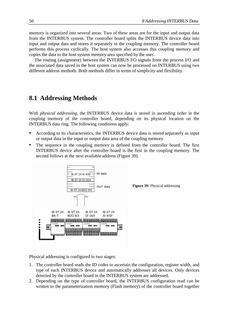
50 8 Addressing INTERBUS Data
memory is organized into several areas. Two of these areas are for the input and output datafrom the INTERBUS system. The controller board splits the INTERBUS device data intoinput and output data and stores it separately in the coupling memory. The controller boardperforms this process cyclically. The host system also accesses this coupling memory andcopies the data to the host system memory area specified by the user.
The routing (assignment) between the INTERBUS I/O signals from the process I/O andthe associated data saved in the host system can now be processed on INTERBUS using twodifferent address methods. Both methods differ in terms of simplicity and flexibility.
8.1 Addressing Methods
With physical addressing, the INTERBUS device data is stored in ascending order in thecoupling memory of the controller board, depending on its physical location on theINTERBUS data ring. The following conditions apply:
• According to its characteristics, the INTERBUS device data is stored separately as inputor output data in the input or output data area of the coupling memory.
• The sequence in the coupling memory is defined from the controller board. The firstINTERBUS device after the controller board is the first in the coupling memory. Thesecond follows at the next available address (Figure 39).
Figure 39: Physical addressing
Physical addressing is configured in two stages:
1. The controller board reads the ID codes to ascertain the configuration, register width, andtype of each INTERBUS device and automatically addresses all devices. Only devicesdetected by the controller board in the INTERBUS system are addressed.
2. Depending on the type of controller board, the INTERBUS configuration read can bewritten to the parameterization memory (Flash memory) of the controller board together
IB ST 24BK-T
IB ST 24BDO 8/3
IB ST 24DI 16/4
IB ST 24AI 4/SF
IB ST 24 DI 16/4
IB ST 24 AI 4/SF
IB ST 24 BDO 8/3
IN data
OUT data
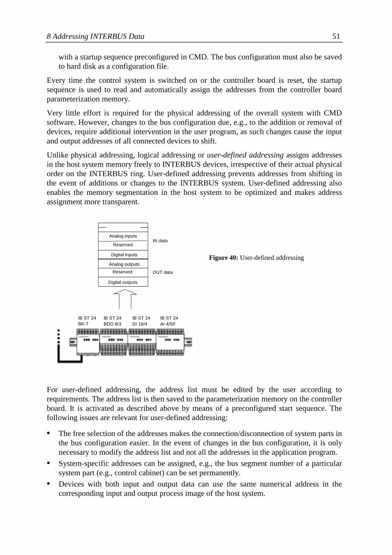
8 Addressing INTERBUS Data 51
with a startup sequence preconfigured in CMD. The bus configuration must also be savedto hard disk as a configuration file.
Every time the control system is switched on or the controller board is reset, the startupsequence is used to read and automatically assign the addresses from the controller boardparameterization memory.
Very little effort is required for the physical addressing of the overall system with CMDsoftware. However, changes to the bus configuration due, e.g., to the addition or removal ofdevices, require additional intervention in the user program, as such changes cause the inputand output addresses of all connected devices to shift.
Unlike physical addressing, logical addressing or user-defined addressing assigns addressesin the host system memory freely to INTERBUS devices, irrespective of their actual physicalorder on the INTERBUS ring. User-defined addressing prevents addresses from shifting inthe event of additions or changes to the INTERBUS system. User-defined addressing alsoenables the memory segmentation in the host system to be optimized and makes addressassignment more transparent.
Figure 40: User-defined addressing
For user-defined addressing, the address list must be edited by the user according torequirements. The address list is then saved to the parameterization memory on the controllerboard. It is activated as described above by means of a preconfigured start sequence. Thefollowing issues are relevant for user-defined addressing:
• The free selection of the addresses makes the connection/disconnection of system parts inthe bus configuration easier. In the event of changes in the bus configuration, it is onlynecessary to modify the address list and not all the addresses in the application program.
• System-specific addresses can be assigned, e.g., the bus segment number of a particularsystem part (e.g., control cabinet) can be set permanently.
• Devices with both input and output data can use the same numerical address in thecorresponding input and output process image of the host system.
IB ST 24 BK-T
IB ST 24 BDO 8/3
IB ST 24 DI 16/4
IB ST 24 AI 4/SF
Digital outputs Reserved
Analog outputs Digital inputs Reserved
Analog inputsIN data
OUT data
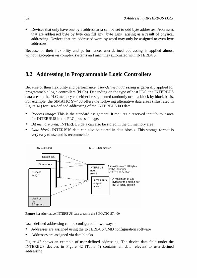
52 8 Addressing INTERBUS Data
• Devices that only have one byte address area can be set to odd byte addresses. Addressesthat are addressed byte by byte can fill any "byte gaps" arising as a result of physicaladdressing. Devices that are addressed word by word may only be assigned to even byteaddresses.
Because of their flexibility and performance, user-defined addressing is applied almostwithout exception on complex systems and machines automated with INTERBUS.
8.2 Addressing in Programmable Logic Controllers
Because of their flexibility and performance, user-defined addressing is generally applied forprogrammable logic controllers (PLCs). Depending on the type of host PLC, the INTERBUSdata area in the PLC memory can either be segmented randomly or on a block by block basis.For example, the SIMATIC S7-400 offers the following alternative data areas (illustrated inFigure 41) for user-defined addressing of the INTERBUS I/O data:
• Process image: This is the standard assignment. It requires a reserved input/output areafor INTERBUS in the PLC process image.
• Bit memory area: INTERBUS data can also be stored in the bit memory area.• Data block: INTERBUS data can also be stored in data blocks. This storage format is
very easy to use and is recommended.
Figure 41: Alternative INTERBUS data areas in the SIMATIC S7-400
User-defined addressing can be configured in two ways:• Addresses are assigned using the INTERBUS CMD configuration software• Addresses are assigned via data blocks
Figure 42 shows an example of user-defined addressing. The device data field under theINTERBUS devices in Figure 42 (Table 7) contains all data relevant to user-definedaddressing.
Data block
Bit memory
Processimage
Used bytheS7 system
INTERBUSinputarea 1
INTERBUSoutputarea 1
S7-400 CPU INTERBUS master
A maximum of 128 bytesfor the input perINTERBUS section
A maximum of 128bytes for the output perINTERBUS section
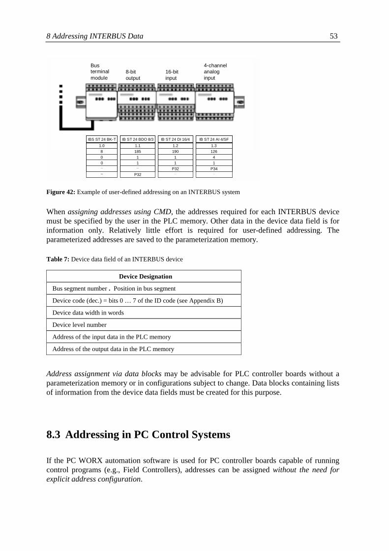
8 Addressing INTERBUS Data 53
Figure 42: Example of user-defined addressing on an INTERBUS system
When assigning addresses using CMD, the addresses required for each INTERBUS devicemust be specified by the user in the PLC memory. Other data in the device data field is forinformation only. Relatively little effort is required for user-defined addressing. Theparameterized addresses are saved to the parameterization memory.
Table 7: Device data field of an INTERBUS device
Device Designation
Bus segment number . Position in bus segment
Device code (dec.) = bits 0 … 7 of the ID code (see Appendix B)
Device data width in words
Device level number
Address of the input data in the PLC memory
Address of the output data in the PLC memory
Address assignment via data blocks may be advisable for PLC controller boards without aparameterization memory or in configurations subject to change. Data blocks containing listsof information from the device data fields must be created for this purpose.
8.3 Addressing in PC Control Systems
If the PC WORX automation software is used for PC controller boards capable of runningcontrol programs (e.g., Field Controllers), addresses can be assigned without the need forexplicit address configuration.
Busterminalmodule
8-bitoutput
16-bitinput
4-channelanaloginput
IBS ST 24 BK-T1.0800__
IB ST 24 BDO 8/31.1185
11_
P32
IB ST 24 DI 16/41.2190
11
P32_
IB ST 24 AI 4/SF1.3126
41
P34_

54 8 Addressing INTERBUS Data
This integrated system solution, which is based on INTERBUS device descriptions of theconnected bus configuration, can use the I/O terminal designations in that configurationdirectly as process variables in the IEC 61131 control program. Users continue to work withfunctional components with which they are familiar from the process world, such as I/Oterminals and signal designations, and do not require any additional knowledge aboutinternal data paths, routing, and addressing.
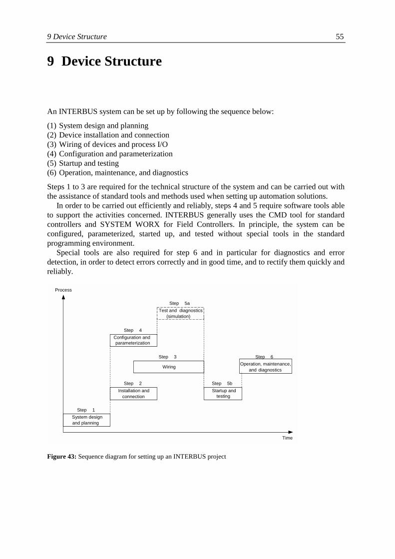
9 Device Structure 55
9 Device Structure
An INTERBUS system can be set up by following the sequence below:
(1) System design and planning(2) Device installation and connection(3) Wiring of devices and process I/O(4) Configuration and parameterization(5) Startup and testing(6) Operation, maintenance, and diagnostics
Steps 1 to 3 are required for the technical structure of the system and can be carried out withthe assistance of standard tools and methods used when setting up automation solutions.
In order to be carried out efficiently and reliably, steps 4 and 5 require software tools ableto support the activities concerned. INTERBUS generally uses the CMD tool for standardcontrollers and SYSTEM WORX for Field Controllers. In principle, the system can beconfigured, parameterized, started up, and tested without special tools in the standardprogramming environment.
Special tools are also required for step 6 and in particular for diagnostics and errordetection, in order to detect errors correctly and in good time, and to rectify them quickly andreliably.
Figure 43: Sequence diagram for setting up an INTERBUS project
System design and planning
Step 1
Configuration and parameterization
Step 4
Test and diagnostics (simulation)
Step 5a
Installation and connection
Step 2 Startup and
testing
Step 5b
Wiring Step 3
Operation, maintenance, and diagnostics
Step 6
Time
Process
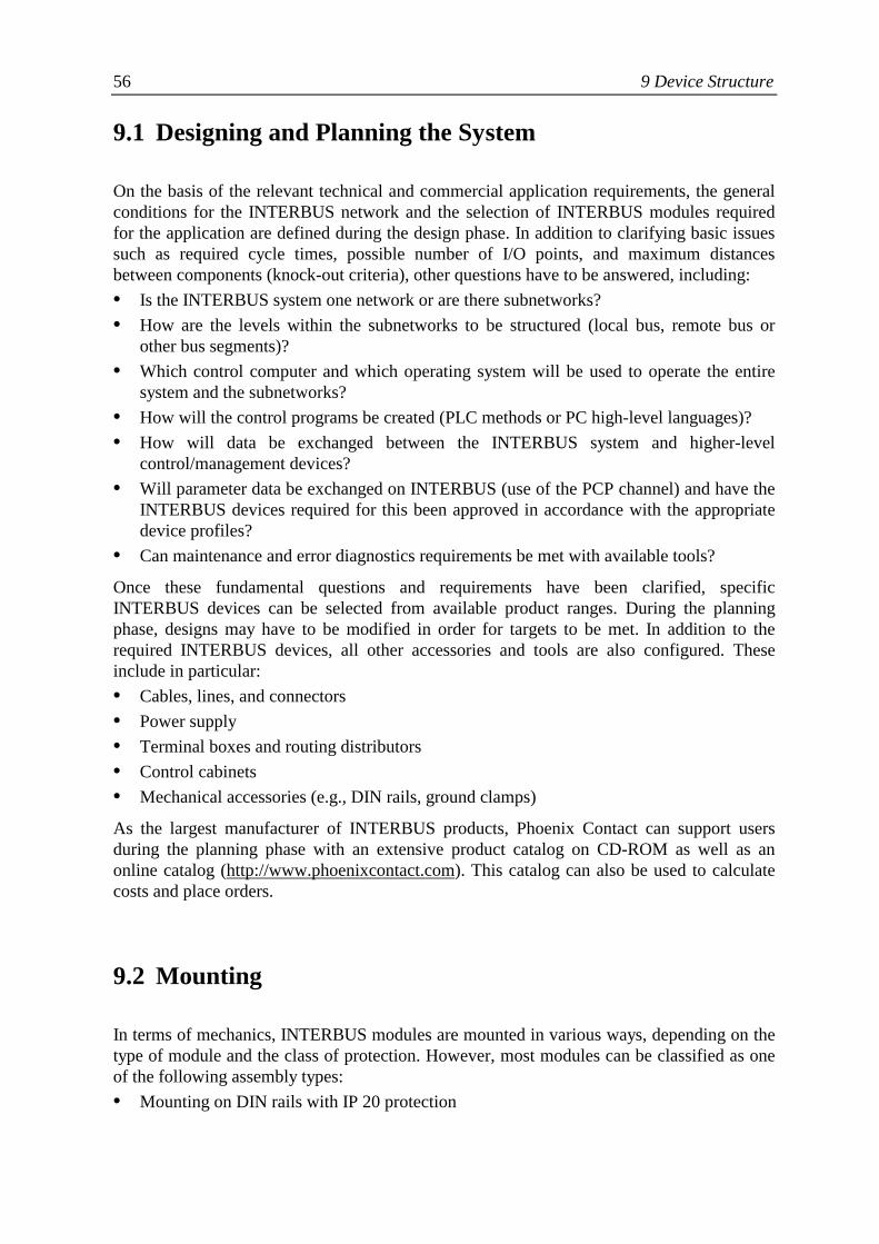
56 9 Device Structure
9.1 Designing and Planning the System
On the basis of the relevant technical and commercial application requirements, the generalconditions for the INTERBUS network and the selection of INTERBUS modules requiredfor the application are defined during the design phase. In addition to clarifying basic issuessuch as required cycle times, possible number of I/O points, and maximum distancesbetween components (knock-out criteria), other questions have to be answered, including:• Is the INTERBUS system one network or are there subnetworks?• How are the levels within the subnetworks to be structured (local bus, remote bus or
other bus segments)?• Which control computer and which operating system will be used to operate the entire
system and the subnetworks?• How will the control programs be created (PLC methods or PC high-level languages)?• How will data be exchanged between the INTERBUS system and higher-level
control/management devices?• Will parameter data be exchanged on INTERBUS (use of the PCP channel) and have the
INTERBUS devices required for this been approved in accordance with the appropriatedevice profiles?
• Can maintenance and error diagnostics requirements be met with available tools?
Once these fundamental questions and requirements have been clarified, specificINTERBUS devices can be selected from available product ranges. During the planningphase, designs may have to be modified in order for targets to be met. In addition to therequired INTERBUS devices, all other accessories and tools are also configured. Theseinclude in particular:• Cables, lines, and connectors• Power supply• Terminal boxes and routing distributors• Control cabinets• Mechanical accessories (e.g., DIN rails, ground clamps)
As the largest manufacturer of INTERBUS products, Phoenix Contact can support usersduring the planning phase with an extensive product catalog on CD-ROM as well as anonline catalog (http://www.phoenixcontact.com). This catalog can also be used to calculatecosts and place orders.
9.2 Mounting
In terms of mechanics, INTERBUS modules are mounted in various ways, depending on thetype of module and the class of protection. However, most modules can be classified as oneof the following assembly types:• Mounting on DIN rails with IP 20 protection
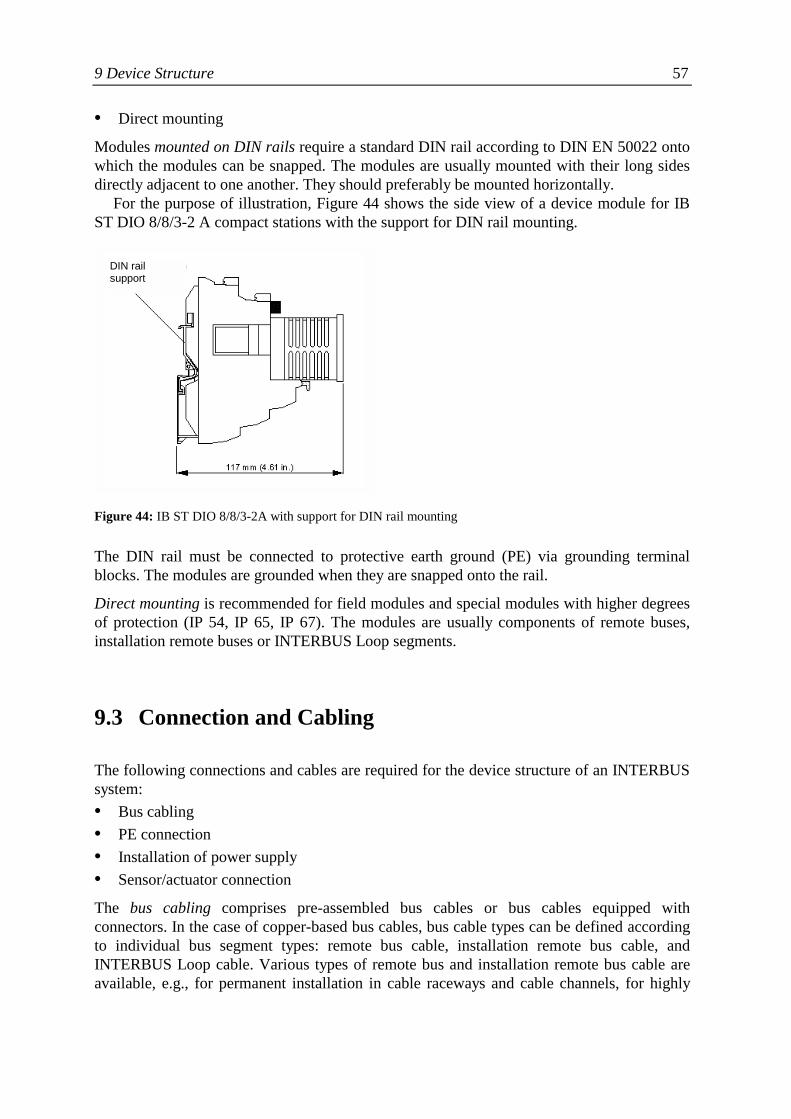
9 Device Structure 57
• Direct mounting
Modules mounted on DIN rails require a standard DIN rail according to DIN EN 50022 ontowhich the modules can be snapped. The modules are usually mounted with their long sidesdirectly adjacent to one another. They should preferably be mounted horizontally.
For the purpose of illustration, Figure 44 shows the side view of a device module for IBST DIO 8/8/3-2 A compact stations with the support for DIN rail mounting.
Figure 44: IB ST DIO 8/8/3-2A with support for DIN rail mounting
The DIN rail must be connected to protective earth ground (PE) via grounding terminalblocks. The modules are grounded when they are snapped onto the rail.
Direct mounting is recommended for field modules and special modules with higher degreesof protection (IP 54, IP 65, IP 67). The modules are usually components of remote buses,installation remote buses or INTERBUS Loop segments.
9.3 Connection and Cabling
The following connections and cables are required for the device structure of an INTERBUSsystem:• Bus cabling• PE connection• Installation of power supply• Sensor/actuator connection
The bus cabling comprises pre-assembled bus cables or bus cables equipped withconnectors. In the case of copper-based bus cables, bus cable types can be defined accordingto individual bus segment types: remote bus cable, installation remote bus cable, andINTERBUS Loop cable. Various types of remote bus and installation remote bus cable areavailable, e.g., for permanent installation in cable raceways and cable channels, for highly
DIN railsupport
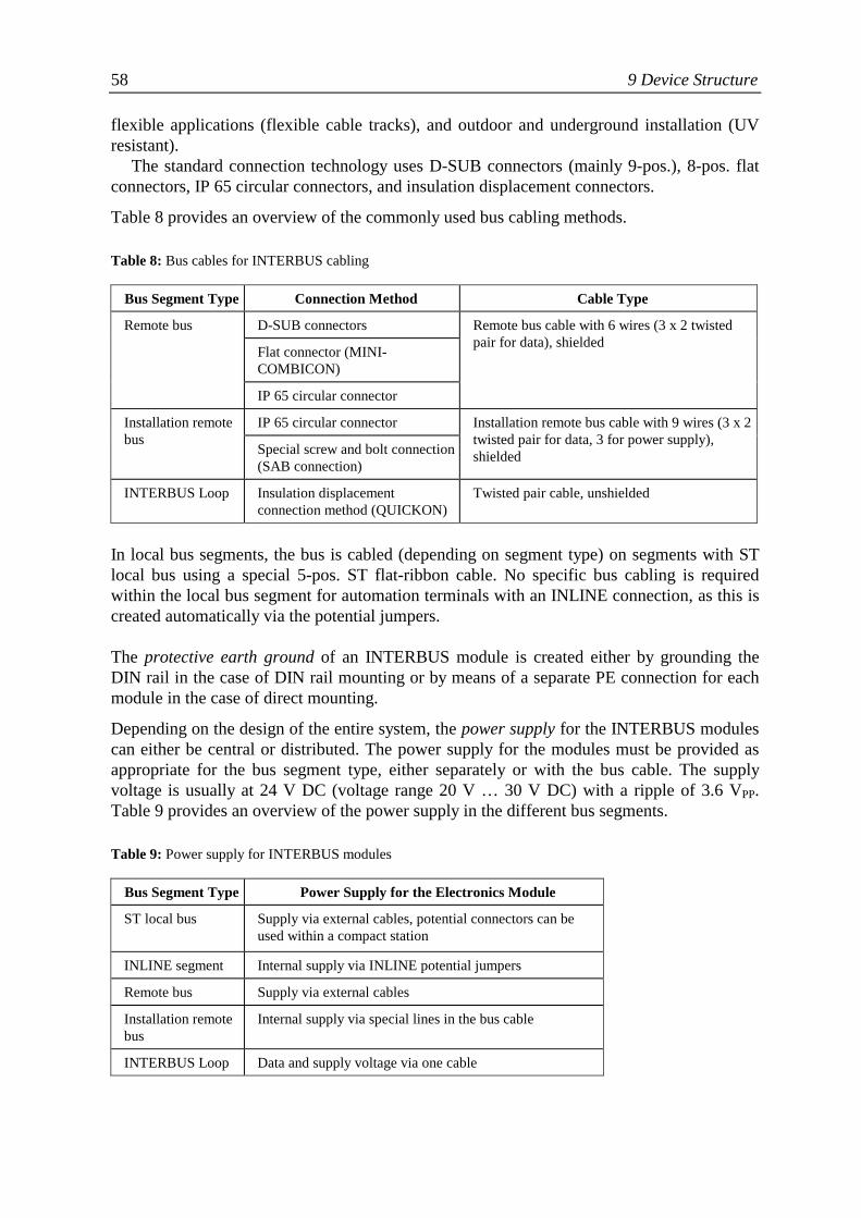
58 9 Device Structure
flexible applications (flexible cable tracks), and outdoor and underground installation (UVresistant).
The standard connection technology uses D-SUB connectors (mainly 9-pos.), 8-pos. flatconnectors, IP 65 circular connectors, and insulation displacement connectors.
Table 8 provides an overview of the commonly used bus cabling methods.
Table 8: Bus cables for INTERBUS cabling
Bus Segment Type Connection Method Cable Type
D-SUB connectors
Flat connector (MINI-COMBICON)
Remote bus
IP 65 circular connector
Remote bus cable with 6 wires (3 x 2 twistedpair for data), shielded
IP 65 circular connectorInstallation remotebus
Special screw and bolt connection(SAB connection)
Installation remote bus cable with 9 wires (3 x 2twisted pair for data, 3 for power supply),shielded
INTERBUS Loop Insulation displacementconnection method (QUICKON)
Twisted pair cable, unshielded
In local bus segments, the bus is cabled (depending on segment type) on segments with STlocal bus using a special 5-pos. ST flat-ribbon cable. No specific bus cabling is requiredwithin the local bus segment for automation terminals with an INLINE connection, as this iscreated automatically via the potential jumpers.
The protective earth ground of an INTERBUS module is created either by grounding theDIN rail in the case of DIN rail mounting or by means of a separate PE connection for eachmodule in the case of direct mounting.
Depending on the design of the entire system, the power supply for the INTERBUS modulescan either be central or distributed. The power supply for the modules must be provided asappropriate for the bus segment type, either separately or with the bus cable. The supplyvoltage is usually at 24 V DC (voltage range 20 V … 30 V DC) with a ripple of 3.6 VPP.Table 9 provides an overview of the power supply in the different bus segments.
Table 9: Power supply for INTERBUS modules
Bus Segment Type Power Supply for the Electronics Module
ST local bus Supply via external cables, potential connectors can beused within a compact station
INLINE segment Internal supply via INLINE potential jumpers
Remote bus Supply via external cables
Installation remotebus
Internal supply via special lines in the bus cable
INTERBUS Loop Data and supply voltage via one cable
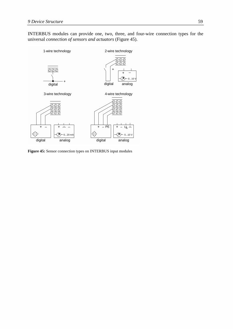
9 Device Structure 59
INTERBUS modules can provide one, two, three, and four-wire connection types for theuniversal connection of sensors and actuators (Figure 45).
Figure 45: Sensor connection types on INTERBUS input modules
0...10 V
+ _
+ _
0...20 mA
+ _
analogdigital
+ _ PE + _ Ub
0...10 V
analogdigital
4-wire technology3-wire technology
+digital
+
digital analog
2-wire technology1-wire technology

60 9 Device Structure
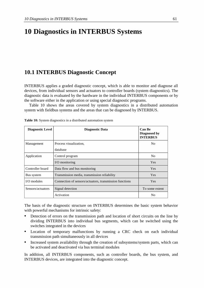
10 Diagnostics in INTERBUS Systems 61
10 Diagnostics in INTERBUS Systems
10.1 INTERBUS Diagnostic Concept
INTERBUS applies a graded diagnostic concept, which is able to monitor and diagnose alldevices, from individual sensors and actuators to controller boards (system diagnostics). Thediagnostic data is evaluated by the hardware in the individual INTERBUS components or bythe software either in the application or using special diagnostic programs.
Table 10 shows the areas covered by system diagnostics in a distributed automationsystem with fieldbus systems and the areas that can be diagnosed by INTERBUS.
Table 10: System diagnostics in a distributed automation system
Diagnostic Level Diagnostic Data Can BeDiagnosed byINTERBUS
Management Process visualization,
database
No
Control program NoApplication
I/O monitoring Yes
Controller board Data flow and bus monitoring Yes
Bus system Transmission media, transmission reliability Yes
I/O modules Connection of sensors/actuators, transmission functions Yes
Signal detection To some extentSensors/actuators
Activation No
The basis of the diagnostic structure on INTERBUS determines the basic system behaviorwith powerful mechanisms for intrinsic safety:• Detection of errors on the transmission path and location of short circuits on the line by
dividing INTERBUS into individual bus segments, which can be switched using theswitches integrated in the devices
• Location of temporary malfunctions by running a CRC check on each individualtransmission path simultaneously in all devices
• Increased system availability through the creation of subsystems/system parts, which canbe activated and deactivated via bus terminal modules
In addition, all INTERBUS components, such as controller boards, the bus system, andINTERBUS devices, are integrated into the diagnostic concept.
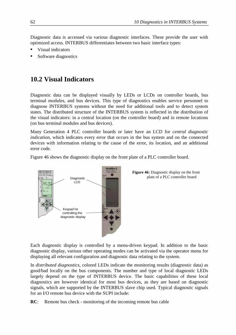
62 10 Diagnostics in INTERBUS Systems
Diagnostic data is accessed via various diagnostic interfaces. These provide the user withoptimized access. INTERBUS differentiates between two basic interface types:• Visual indicators• Software diagnostics
10.2 Visual Indicators
Diagnostic data can be displayed visually by LEDs or LCDs on controller boards, busterminal modules, and bus devices. This type of diagnostics enables service personnel todiagnose INTERBUS systems without the need for additional tools and to detect systemstates. The distributed structure of the INTERBUS system is reflected in the distribution ofthe visual indicators: in a central location (on the controller board) and in remote locations(on bus terminal modules and bus devices).
Many Generation 4 PLC controller boards or later have an LCD for central diagnosticindication, which indicates every error that occurs in the bus system and on the connecteddevices with information relating to the cause of the error, its location, and an additionalerror code.
Figure 46 shows the diagnostic display on the front plate of a PLC controller board.
Figure 46: Diagnostic display on the frontplate of a PLC controller board
Each diagnostic display is controlled by a menu-driven keypad. In addition to the basicdiagnostic display, various other operating modes can be activated via the operator menu fordisplaying all relevant configuration and diagnostic data relating to the system.
In distributed diagnostics, colored LEDs indicate the monitoring results (diagnostic data) asgood/bad locally on the bus components. The number and type of local diagnostic LEDslargely depend on the type of INTERBUS device. The basic capabilities of these localdiagnostics are however identical for most bus devices, as they are based on diagnosticsignals, which are supported by the INTERBUS slave chip used. Typical diagnostic signalsfor an I/O remote bus device with the SUPI include:
RC: Remote bus check - monitoring of the incoming remote bus cable
Keypad forcontrolling the
diagnostic display
DiagnosticLCD
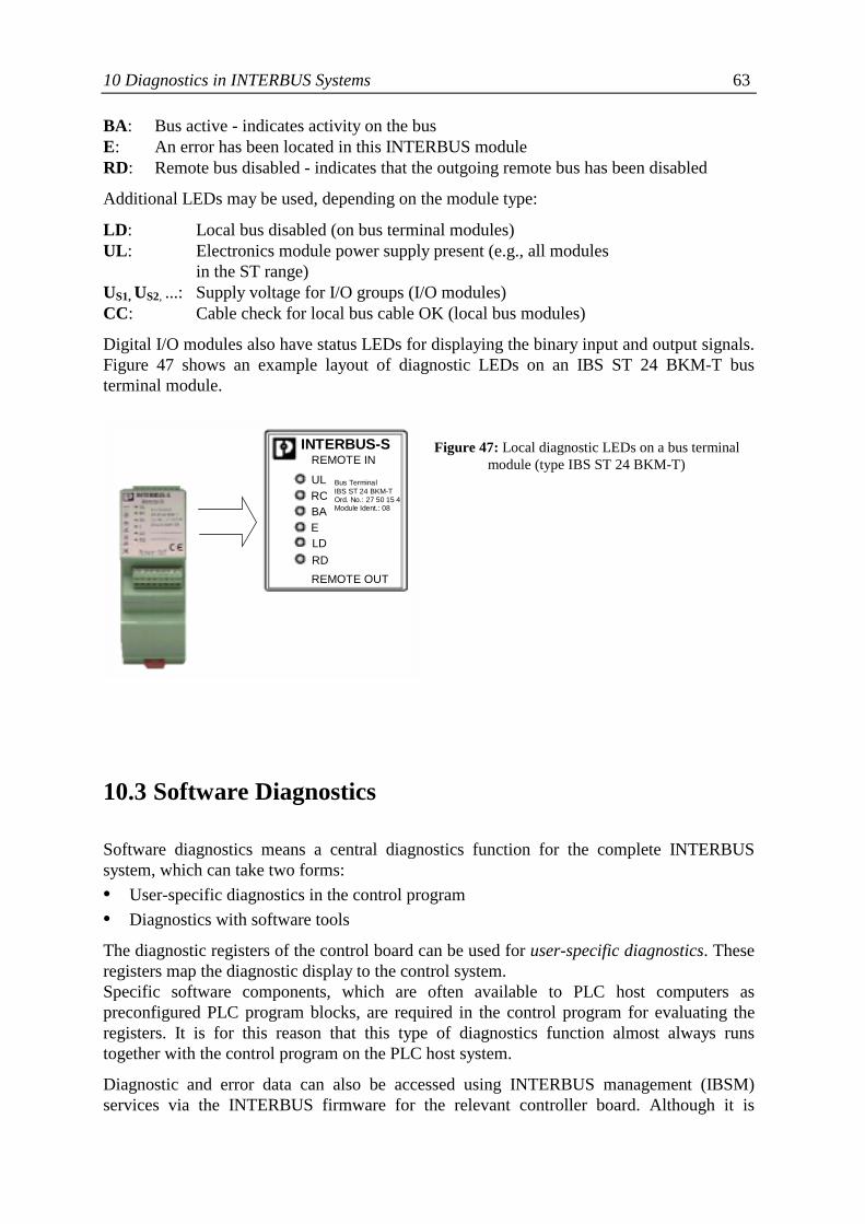
10 Diagnostics in INTERBUS Systems 63
BA: Bus active - indicates activity on the busE: An error has been located in this INTERBUS moduleRD: Remote bus disabled - indicates that the outgoing remote bus has been disabled
Additional LEDs may be used, depending on the module type:
LD: Local bus disabled (on bus terminal modules)UL: Electronics module power supply present (e.g., all modules
in the ST range)US1, US2, ...: Supply voltage for I/O groups (I/O modules)CC: Cable check for local bus cable OK (local bus modules)
Digital I/O modules also have status LEDs for displaying the binary input and output signals.Figure 47 shows an example layout of diagnostic LEDs on an IBS ST 24 BKM-T busterminal module.
Figure 47: Local diagnostic LEDs on a bus terminalmodule (type IBS ST 24 BKM-T)
10.3 Software Diagnostics
Software diagnostics means a central diagnostics function for the complete INTERBUSsystem, which can take two forms:• User-specific diagnostics in the control program• Diagnostics with software tools
The diagnostic registers of the control board can be used for user-specific diagnostics. Theseregisters map the diagnostic display to the control system.Specific software components, which are often available to PLC host computers aspreconfigured PLC program blocks, are required in the control program for evaluating theregisters. It is for this reason that this type of diagnostics function almost always runstogether with the control program on the PLC host system.
Diagnostic and error data can also be accessed using INTERBUS management (IBSM)services via the INTERBUS firmware for the relevant controller board. Although it is
INTERBUS-S
ULRCBAELDRD
REMOTE IN
REMOTE OUT
Bus TerminalIBS ST 24 BKM-TOrd. No.: 27 50 15 4Module Ident.: 08

64 10 Diagnostics in INTERBUS Systems
relatively difficult to integrate these services into a user program, they do enable the systemto be diagnosed under all possible conditions.
By far the most frequently used software tool for diagnostics on INTERBUS systems is PCWORX/the CMD tool. These tools have a special diagnostics part with which anINTERBUS system can perform simple practical checks for and statistically evaluatemessages relating to malfunctions and errors across the entire system and locally (device-specific).
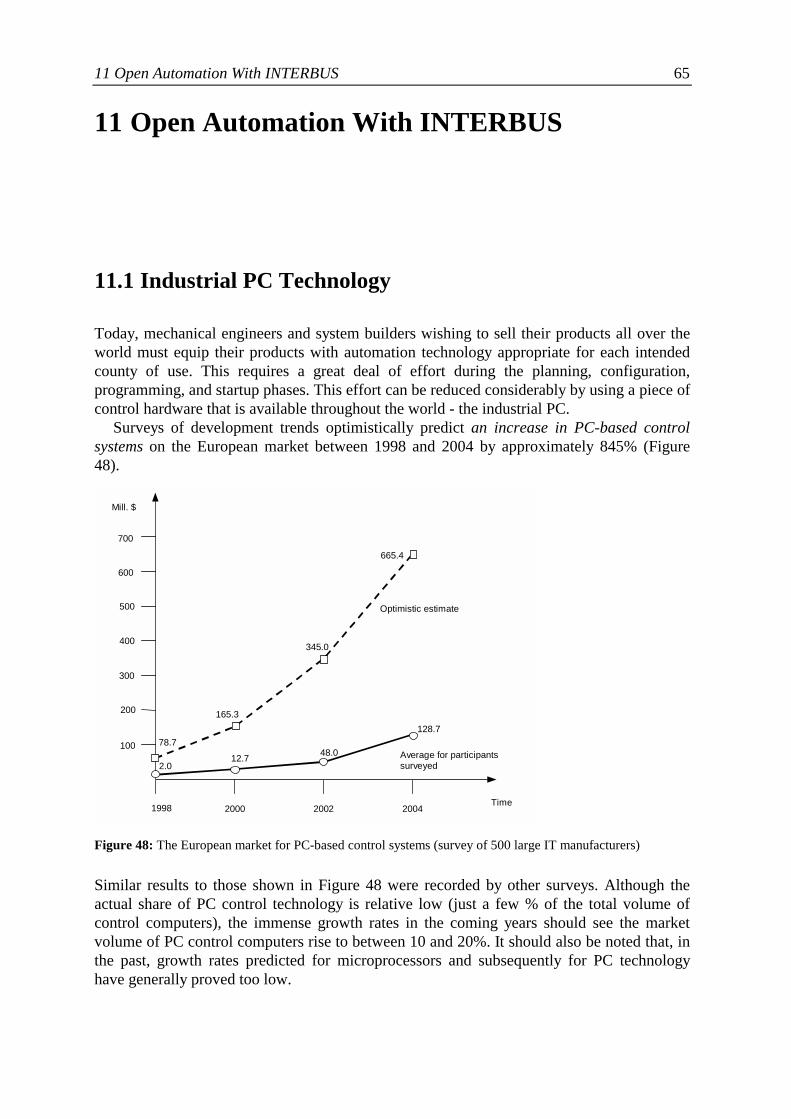
11 Open Automation With INTERBUS 65
11 Open Automation With INTERBUS
11.1 Industrial PC Technology
Today, mechanical engineers and system builders wishing to sell their products all over theworld must equip their products with automation technology appropriate for each intendedcounty of use. This requires a great deal of effort during the planning, configuration,programming, and startup phases. This effort can be reduced considerably by using a piece ofcontrol hardware that is available throughout the world - the industrial PC.
Surveys of development trends optimistically predict an increase in PC-based controlsystems on the European market between 1998 and 2004 by approximately 845% (Figure48).
Figure 48: The European market for PC-based control systems (survey of 500 large IT manufacturers)
Similar results to those shown in Figure 48 were recorded by other surveys. Although theactual share of PC control technology is relative low (just a few % of the total volume ofcontrol computers), the immense growth rates in the coming years should see the marketvolume of PC control computers rise to between 10 and 20%. It should also be noted that, inthe past, growth rates predicted for microprocessors and subsequently for PC technologyhave generally proved too low.
Time1998 2000 2002 2004
Mill. $
600
500
400
300
200
100
Optimistic estimate
Average for participantssurveyed2.0
12.7 48.0
128.778.7
165.3
345.0
665.4
700
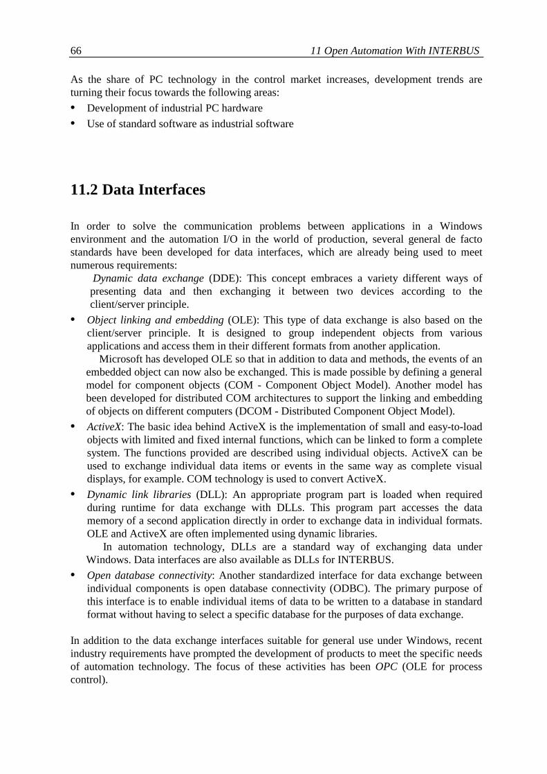
66 11 Open Automation With INTERBUS
As the share of PC technology in the control market increases, development trends areturning their focus towards the following areas:• Development of industrial PC hardware• Use of standard software as industrial software
11.2 Data Interfaces
In order to solve the communication problems between applications in a Windowsenvironment and the automation I/O in the world of production, several general de factostandards have been developed for data interfaces, which are already being used to meetnumerous requirements:
Dynamic data exchange (DDE): This concept embraces a variety different ways ofpresenting data and then exchanging it between two devices according to theclient/server principle.
• Object linking and embedding (OLE): This type of data exchange is also based on theclient/server principle. It is designed to group independent objects from variousapplications and access them in their different formats from another application.
Microsoft has developed OLE so that in addition to data and methods, the events of anembedded object can now also be exchanged. This is made possible by defining a generalmodel for component objects (COM - Component Object Model). Another model hasbeen developed for distributed COM architectures to support the linking and embeddingof objects on different computers (DCOM - Distributed Component Object Model).
• ActiveX: The basic idea behind ActiveX is the implementation of small and easy-to-loadobjects with limited and fixed internal functions, which can be linked to form a completesystem. The functions provided are described using individual objects. ActiveX can beused to exchange individual data items or events in the same way as complete visualdisplays, for example. COM technology is used to convert ActiveX.
• Dynamic link libraries (DLL): An appropriate program part is loaded when requiredduring runtime for data exchange with DLLs. This program part accesses the datamemory of a second application directly in order to exchange data in individual formats.OLE and ActiveX are often implemented using dynamic libraries.
In automation technology, DLLs are a standard way of exchanging data underWindows. Data interfaces are also available as DLLs for INTERBUS.
• Open database connectivity: Another standardized interface for data exchange betweenindividual components is open database connectivity (ODBC). The primary purpose ofthis interface is to enable individual items of data to be written to a database in standardformat without having to select a specific database for the purposes of data exchange.
In addition to the data exchange interfaces suitable for general use under Windows, recentindustry requirements have prompted the development of products to meet the specific needsof automation technology. The focus of these activities has been OPC (OLE for processcontrol).
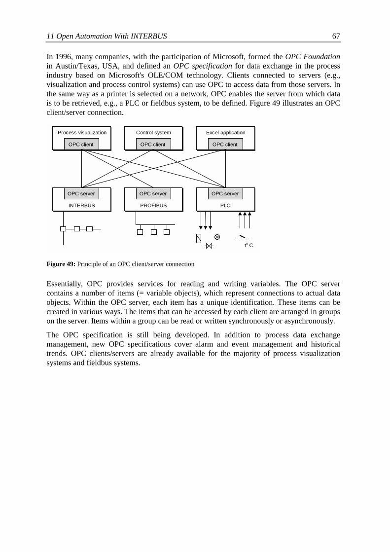
11 Open Automation With INTERBUS 67
In 1996, many companies, with the participation of Microsoft, formed the OPC Foundationin Austin/Texas, USA, and defined an OPC specification for data exchange in the processindustry based on Microsoft's OLE/COM technology. Clients connected to servers (e.g.,visualization and process control systems) can use OPC to access data from those servers. Inthe same way as a printer is selected on a network, OPC enables the server from which datais to be retrieved, e.g., a PLC or fieldbus system, to be defined. Figure 49 illustrates an OPCclient/server connection.
Figure 49: Principle of an OPC client/server connection
Essentially, OPC provides services for reading and writing variables. The OPC servercontains a number of items (= variable objects), which represent connections to actual dataobjects. Within the OPC server, each item has a unique identification. These items can becreated in various ways. The items that can be accessed by each client are arranged in groupson the server. Items within a group can be read or written synchronously or asynchronously.
The OPC specification is still being developed. In addition to process data exchangemanagement, new OPC specifications cover alarm and event management and historicaltrends. OPC clients/servers are already available for the majority of process visualizationsystems and fieldbus systems.
INTERBUSINTERBUS
OPC server
ProfibusPROFIBUS
OPC server
SPSPLC
OPC server
ProzeßvisualisierungProcess visualization
OPC client
LeitsystemControl system
OPC client
Exel-AnwendungExcel application
OPC client
t0 C
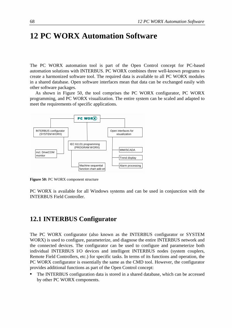
68 12 PC WORX Automation Software
12 PC WORX Automation Software
The PC WORX automation tool is part of the Open Control concept for PC-basedautomation solutions with INTERBUS. PC WORX combines three well-known programs tocreate a harmonized software tool. The required data is available to all PC WORX modulesin a shared database. Open software interfaces mean that data can be exchanged easily withother software packages.
As shown in Figure 50, the tool comprises the PC WORX configurator, PC WORXprogramming, and PC WORX visualization. The entire system can be scaled and adapted tomeet the requirements of specific applications.
Figure 50: PC WORX component structure
PC WORX is available for all Windows systems and can be used in conjunction with theINTERBUS Field Controller.
12.1 INTERBUS Configurator
The PC WORX configurator (also known as the INTERBUS configurator or SYSTEMWORX) is used to configure, parameterize, and diagnose the entire INTERBUS network andthe connected devices. The configurator can be used to configure and parameterize bothindividual INTERBUS I/O devices and intelligent INTERBUS nodes (system couplers,Remote Field Controllers, etc.) for specific tasks. In terms of its functions and operation, thePC WORX configurator is essentially the same as the CMD tool. However, the configuratorprovides additional functions as part of the Open Control concept:• The INTERBUS configuration data is stored in a shared database, which can be accessed
by other PC WORX components.
INTERBUS configurator(SYSTEM WORX)
IEC 61131 programming(PROGRAM WORX)
Open interfaces forvisualization
incl. DriveCOMmonitor
Machine sequentialfunction chart add-on
MMI/SCADA
Trend display
Alarm processing
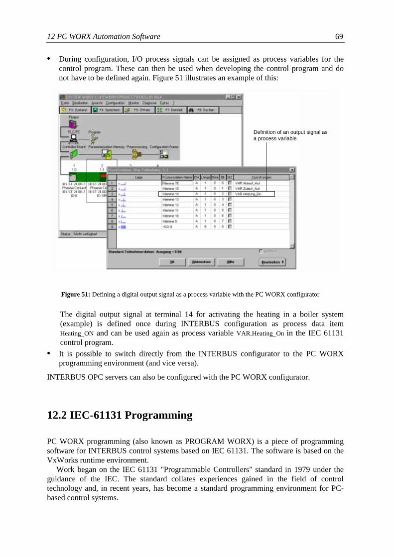
12 PC WORX Automation Software 69
• During configuration, I/O process signals can be assigned as process variables for thecontrol program. These can then be used when developing the control program and donot have to be defined again. Figure 51 illustrates an example of this:
Figure 51: Defining a digital output signal as a process variable with the PC WORX configurator
The digital output signal at terminal 14 for activating the heating in a boiler system(example) is defined once during INTERBUS configuration as process data itemHeating_ON and can be used again as process variable VAR.Heating_On in the IEC 61131control program.
• It is possible to switch directly from the INTERBUS configurator to the PC WORXprogramming environment (and vice versa).
INTERBUS OPC servers can also be configured with the PC WORX configurator.
12.2 IEC-61131 Programming
PC WORX programming (also known as PROGRAM WORX) is a piece of programmingsoftware for INTERBUS control systems based on IEC 61131. The software is based on theVxWorks runtime environment.
Work began on the IEC 61131 "Programmable Controllers" standard in 1979 under theguidance of the IEC. The standard collates experiences gained in the field of controltechnology and, in recent years, has become a standard programming environment for PC-based control systems.
Definition of an output signal asa process variable
70 12 PC WORX Automation Software
Taking the hardware and software model of a modern control structure as its basis, Part 3(IEC 61131-3) describes five powerful languages for structuring and programming:
• Function block diagram (FBD)• Instruction list (IL)• Sequential flow chart (SFC)• Ladder diagram (LD)• Structured text (ST)
PC WORX programming supports all five IEC 61131 languages as well as an additionalapplication-specific machine sequential function chart language (MSFC).
12.3 Visualization
As an option, PC WORX supports the integration of various process visualization andcontrol systems. The data required for visualization can be imported into all systems directlyfrom the PC WORX programming environment or from standard Windows programs (Excel,Access, etc.) via the Windows data interfaces (DDE, OLE, ODBC). Data exchange via anOPC client/server interface is also possible.

Index 71
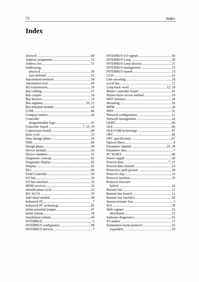
72 Index
Index
ActiveX ............................................................... 66Address assignment ............................................. 53Address list.......................................................... 51Addressing
physical ........................................................... 50user-defined..................................................... 51
Automation terminal............................................ 18Automation tool................................................... 69Bit transmission................................................... 24Bus cabling.......................................................... 57Bus coupler ......................................................... 10Bus devices.......................................................... 14Bus segment .................................................. 10, 15Bus terminal module ........................................... 14COM.................................................................... 66Compact station................................................... 43Controller
programmable logic......................................... 41Controller board ........................................ 7, 13, 39Coprocessor board............................................... 40Data cycle............................................................ 25Data storage phase............................................... 26DDE .................................................................... 66Design phase ....................................................... 56Device module..................................................... 43Device numbers................................................... 22Diagnostic concept .............................................. 61Diagnostic display ............................................... 62Display ................................................................ 62DLL..................................................................... 66Field Controller ................................................... 39I/O bus................................................................. 16I/O bus interface .................................................. 35IBSM services ..................................................... 32Identification cycle .............................................. 25IEC 61131 ........................................................... 70Individual module ............................................... 48Industrial PC.......................................................... 7Industrial PC technology ..................................... 65Inline potential jumper ........................................ 47Inline station........................................................ 18Installation system............................................... 44INTERBUS ........................................................... 5INTERBUS configurator..................................... 69INTERBUS devices .............................................. 7
INTERBUS I/O signals .......................................50INTERBUS Loop................................................20INTERBUS Loop devices ...................................37INTERBUS management ....................................31INTERBUS master..............................................13LCD.....................................................................42Line encoding ......................................................24Local bus .............................................................11Loop-back word ............................................12, 26Master controller board .......................................41Master/slave access method.................................10MFP interface......................................................34Mounting .............................................................56MPM ...................................................................30MXI.....................................................................31Network configuration.........................................21Network management..........................................24ODBC..................................................................66OLE.....................................................................66OLE/COM technology ........................................67OPC.....................................................................66OPC specification................................................67Optical fibers .........................................................8Parameter channel .........................................23, 28Parameter data .......................................................7PC WORX...........................................................40Power supply .......................................................58Process data .....................................................7, 27Process data channel............................................23Protective earth ground .......................................58Protocol chip .......................................................33Protocol machine.................................................33Protocol structure
hybrid ..............................................................24Remote bus ..........................................................11Remote bus branch ..............................................11Remote bus interface ...........................................36Sensor/actuator bus................................................5SGI ......................................................................30Shift register ........................................................25
distributed........................................................12Software diagnostics............................................63ST station ............................................................17Summation frame protocol ..................................25
expanded..........................................................29

Index 73

Appendix 75
Appendix
Appendix A: Important Addresses
Manufacturer
Phoenix Contact GmbH & Co. KGPostfach 1341D-32819 Blomberg, GermanyorFlachsmarktstr. 8-28D-32825 Blomberg, GermanyPhone: +49 - 52 35 - 34 12 00Fax: +49 - 52 35 - 30 0E-mail: [email protected]: http://www.phoenixcontact.com
INTERBUS Clubs
INTERBUS Club Deutschland e.V.Head OfficePostfach 1108D-32817 Blomberg, GermanyPhone: +49 - 52 35 - 34 21 00Fax: +49 - 52 35 - 34 12 34E-mail: [email protected]: http://www.interbusclub.com
Open Control Concept
OPC Foundation20423 State Road 7Suite 292Boca Ralon, FL 33498Phone: (561) 477 – 1375Fax: (561) 477 – 0520E-mail: [email protected]: http://www.opcfoundation.org
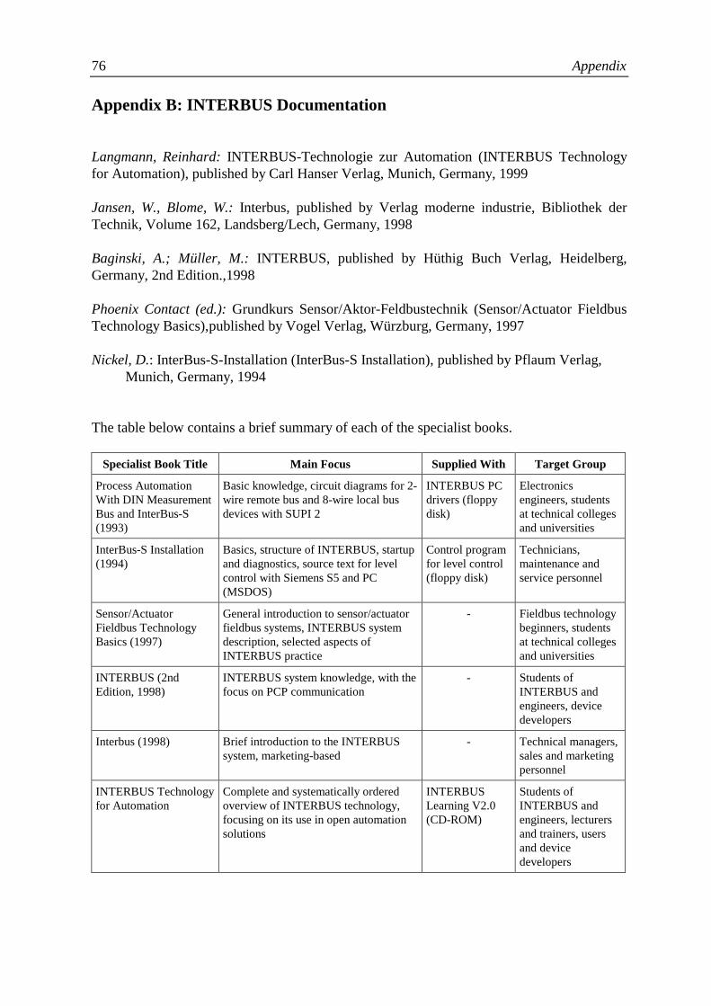
76 Appendix
Appendix B: INTERBUS Documentation
Langmann, Reinhard: INTERBUS-Technologie zur Automation (INTERBUS Technologyfor Automation), published by Carl Hanser Verlag, Munich, Germany, 1999
Jansen, W., Blome, W.: Interbus, published by Verlag moderne industrie, Bibliothek derTechnik, Volume 162, Landsberg/Lech, Germany, 1998
Baginski, A.; Müller, M.: INTERBUS, published by Hüthig Buch Verlag, Heidelberg,Germany, 2nd Edition.,1998
Phoenix Contact (ed.): Grundkurs Sensor/Aktor-Feldbustechnik (Sensor/Actuator FieldbusTechnology Basics),published by Vogel Verlag, Würzburg, Germany, 1997
Nickel, D.: InterBus-S-Installation (InterBus-S Installation), published by Pflaum Verlag,Munich, Germany, 1994
The table below contains a brief summary of each of the specialist books.
Specialist Book Title Main Focus Supplied With Target Group
Process AutomationWith DIN MeasurementBus and InterBus-S(1993)
Basic knowledge, circuit diagrams for 2-wire remote bus and 8-wire local busdevices with SUPI 2
INTERBUS PCdrivers (floppydisk)
Electronicsengineers, studentsat technical collegesand universities
InterBus-S Installation(1994)
Basics, structure of INTERBUS, startupand diagnostics, source text for levelcontrol with Siemens S5 and PC(MSDOS)
Control programfor level control(floppy disk)
Technicians,maintenance andservice personnel
Sensor/ActuatorFieldbus TechnologyBasics (1997)
General introduction to sensor/actuatorfieldbus systems, INTERBUS systemdescription, selected aspects ofINTERBUS practice
- Fieldbus technologybeginners, studentsat technical collegesand universities
INTERBUS (2ndEdition, 1998)
INTERBUS system knowledge, with thefocus on PCP communication
- Students ofINTERBUS andengineers, devicedevelopers
Interbus (1998) Brief introduction to the INTERBUSsystem, marketing-based
- Technical managers,sales and marketingpersonnel
INTERBUS Technologyfor Automation
Complete and systematically orderedoverview of INTERBUS technology,focusing on its use in open automationsolutions
INTERBUSLearning V2.0(CD-ROM)
Students ofINTERBUS andengineers, lecturersand trainers, usersand devicedevelopers