Interbody Cage Project Description
9
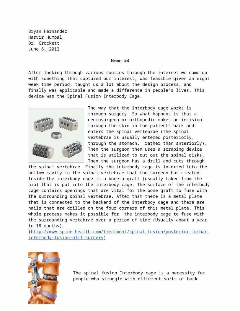
Bryan Hernandez Harvir Humpal Dr. Crockett June 6, 2012 Memo #4 After looking through various sources through the internet we came up with something that captured our interest, was feasible given an eight week time period, taught us a lot about the design process, and finally was applicable and made a difference in people’s lives. This device was the Spinal Fusion Interbody Cage. The way that the interbody cage works is through surgery. So what happens is that a neurosurgeon or orthopedic makes an incision through the skin in the patients back and enters the spinal vertebrae (the spinal vertebrae is usually entered posteriorly, through the stomach, rather than anteriorly). Then the surgeon then uses a scraping device that is utilized to cut out the spinal disks. Then the surgeon has a drill and cuts through the spinal vertebrae. Finally the interbody cage is inserted into the hollow cavity in the spinal vertebrae that the surgeon has created. Inside the interbody cage is a bone a graft (usually taken from the hip) that is put into the interbody cage. The surface of the interbody cage contains openings that are vital for the bone graft to fuse with the surrounding spinal vertebrae. After that there is a metal plate that is connected to the backend of the interbody cage and there are nails that are drilled on the four corners of this metal plate. This whole process makes it possible for the interbody cage to fuse with the surrounding vertebrae over a period of time (Usually about a year to 18 months). (http://www.spine-health.com/treatment/spinal-fusion/posterior-lumbar- interbody-fusion-plif-surgery ) The spinal fusion Interbody cage is a necessity for people who struggle with different sorts of back
-
Upload
harvir-humpal -
Category
Documents
-
view
27 -
download
0
Transcript of Interbody Cage Project Description
Bryan HernandezHarvir HumpalDr. CrockettJune 6, 2012
Memo #4
After looking through various sources through the internet we came up with something that captured our interest, was feasible given an eight week time period, taught us a lot about the design process, and finally was applicable and made a difference in people’s lives. This device was the Spinal Fusion Interbody Cage.
The way that the interbody cage works is through surgery. So what happens is that a neurosurgeon or orthopedic makes an incision through the skin in the patients
back and enters the spinal vertebrae (the spinal vertebrae is usually entered posteriorly, through the stomach, rather than anteriorly). Then the surgeon then uses a scraping device that is utilized to cut out the spinal disks. Then the surgeon has a drill and cuts through the spinal vertebrae. Finally the interbody cage is inserted into the hollow cavity in the spinal vertebrae that the surgeon has created. Inside the interbody cage is a bone a graft (usually taken from the hip) that is put into the interbody cage. The surface of the interbody cage contains openings that are vital for the bone graft to fuse with the surrounding spinal vertebrae. After that
there is a metal plate that is connected to the backend of the interbody cage and there are nails that are drilled on the four corners of this metal plate. This whole process makes it possible for the interbody cage to fuse with the surrounding vertebrae over a period of time (Usually about a year to 18 months). (http://www.spine-health.com/treatment/spinal-fusion/posterior-lumbar-interbody-fusion-plif-surgery)
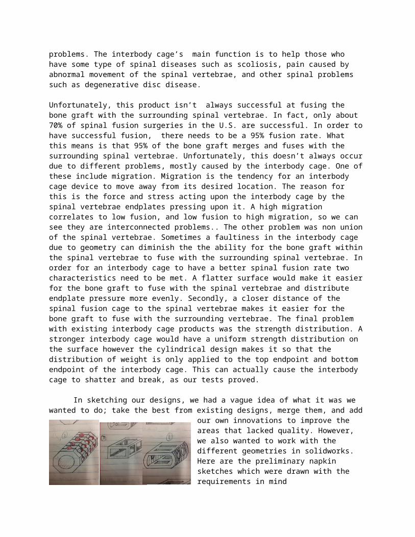
The spinal fusion Interbody cage is a necessity for people who struggle with different sorts of back problems. The interbody cage’s main function is to help those who have some type of spinal diseases such as scoliosis, pain caused by abnormal movement of the spinal vertebrae, and other spinal problems such as degenerative disc disease.
Unfortunately, this product isn’t always successful at fusing the bone graft with the surrounding spinal vertebrae. In fact, only about 70% of spinal fusion surgeries in the U.S. are successful. In order to have successful fusion, there needs to be a 95% fusion rate. What this means is that 95% of the bone graft merges and fuses with the surrounding spinal vertebrae. Unfortunately,
this doesn’t always occur due to different problems, mostly caused by the interbody cage. One of these include migration. Migration is the tendency for an interbody cage device to move away from its desired location. The reason for this is the force and stress acting upon the interbody cage by the spinal vertebrae endplates pressing upon it. A high migration correlates to low fusion, and low fusion to high migration, so we can see they are interconnected problems.. The other problem was non union of the spinal vertebrae. Sometimes a faultiness in the interbody cage due to geometry can diminish the the ability for the bone graft within the spinal vertebrae to fuse with the surrounding spinal vertebrae. In order for an interbody cage to have a better spinal fusion rate two characteristics need to be met. A flatter surface would make it easier for the bone graft to fuse with the spinal vertebrae and distribute endplate pressure more evenly. Secondly, a closer distance of the spinal fusion cage to the spinal vertebrae makes it easier for the bone graft to fuse with the surrounding vertebrae. The final problem with existing interbody cage products was the strength distribution. A stronger interbody cage would have a uniform strength distribution on the surface however the cylindrical design makes it so that the distribution of weight is only applied to the top endpoint and bottom endpoint of the interbody cage. This can actually cause the interbody cage to shatter and break, as our tests proved.
In sketching our designs, we had a vague idea of what it was we wanted to do; take the best from existing designs, merge them, and add our own innovations
to improve the areas that lacked quality. However, we also wanted to work with the different geometries in solidworks. Here are the preliminary napkin sketches which were drawn with the requirements in mind
There is clearly an increase in surface area as well as the flat surfaces our team was aiming for to address the distribution of
weight. However after looking at our design matrix we believed that the second design had been more appropriate.
Design Matrix
Design Requirements Slot Design Octagonal Design Rectangular Design
Migration (1-5) 3 4 2
Strength (1-5) 4 3 5
Fusibility (1-7) 4 7 2
Cost (1-3) 3 2 1
Total 14 16 10
There are some clarifications and reasoning for our design matrix. Migration is the tendency for the interbody cage to move away from its desired location. A higher
score means that there is lower migration. Fusibility is ability for the bone graft to fuse with the surrounding spinal vertebrae through the porous openings on the surface of the interbody cage. The reason cost is ranked lowest is due to the fact that the audience that’s receiving this prototype are hospitals and physicians and not everyday people. If this was for everyday consumers than the price ranking would be higher. Fusibility was ranked the highest for the octagonal prototype since it was closer to the spinal vertebrae (An octagonal shaped prototype is more likely to resemble the cylindrical cavity that is cut through by the cylindrical drill). Finally a higher score means that our design requirements have been met more often.
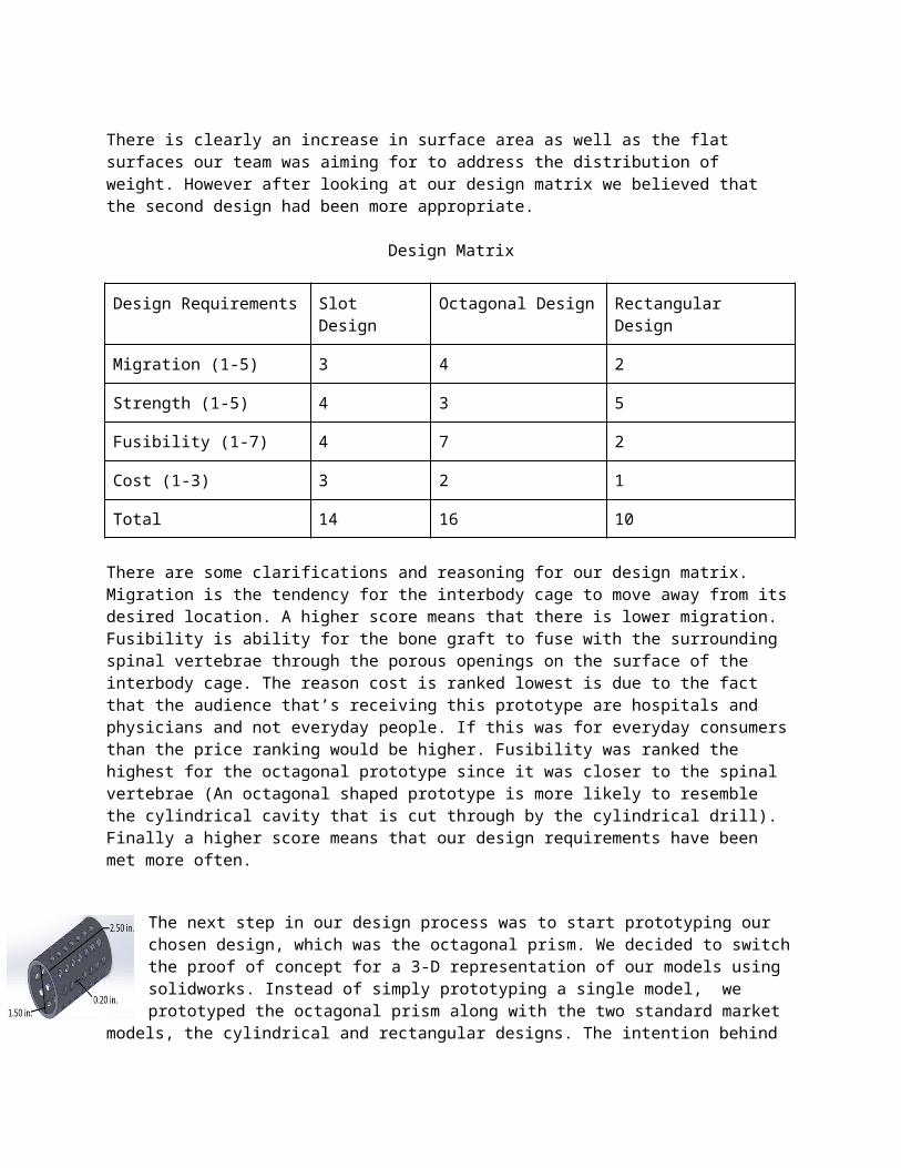
The next step in our design process was to start prototyping our chosen design, which was the octagonal prism. We decided to switch the proof of concept for a 3-D representation of our models using solidworks. Instead of simply prototyping a single model, we prototyped the octagonal prism along with the two standard market models, the cylindrical and rectangular designs.
The intention behind this was so that we would have something to test our design against, to be able to compare and contrast and get results that meant something to us.
This is the octagonal design. We decided to not build it to scale, because a bigger prototype would be easier to work with during testing. The standard prototypes were also blown up in scale for the same purpose and also to maintain equality and fairness when we conduct the tests.
Once our prototypes were built on SolidWorks, it was time to go ahead and build solid models of them. This is where we put our knowledge of rapid prototyping to use for the first time. Initially, we wanted to prototype using the ZCORP machine because of the porous texture it builds thanks to the powder. The thought behind this was a porous surface in our design would help with me migration issue, since the adjacent vertebrae would be able to heal into the pores and provide a secure anchor. However, we faced problems in prototyping because the binder was not working properly, so
we had to use the Fused Deposition Modeling (FDM) machine. This is how they looked after the NaOH bath they were dipped into in order to clean the support material:

Prototyping was a success, and the following step was to test our prototypes. Our main testable requirements were surface area and strength, so we designed two tests to see how well our models performed.
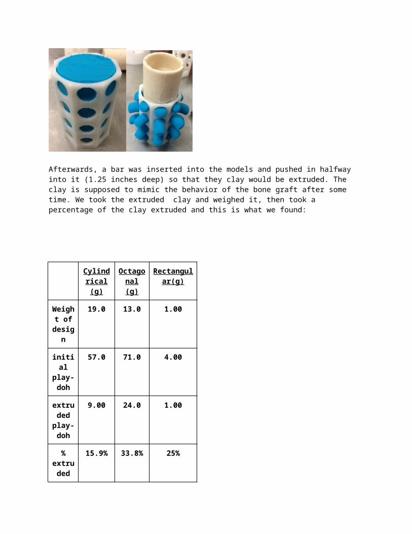
We believed that one way in which we could fix the fusibility problem was by increasing the surface area of our model so that more bone graft would be exposed. In order to test this, we decided to use clay. We first weighed our models, then filled them with as much clay as fit in them, then weighed them again.
Afterwards, a bar was inserted into the models and pushed in halfway into it (1.25 inches deep) so that they clay would be extruded. The clay is supposed to mimic the behavior of the bone graft after some time. We took the extruded clay and weighed it, then took a percentage of the clay extruded and this is what we found:
Cylindrical (g)
Octagonal (g)
Rectangular(g)
Weight of desig
n
19.0 13.0 1.00
initial
play-doh
57.0 71.0 4.00
extruded play-doh
9.00 24.0 1.00
% 15.9% 33.8% 25%
extruded
length
pushed
1.20 in.
1.20 in.
0.80 in.
weight to collapse
------ 16.6 (Kg)
8.72 (kg)
Our design had a 33.8% extrusion rate, which is twice as much as the standard cylindrical and almost 10% higher than the rectangular shape. As we hoped and predicted, our design was superior to the other two in this area of testing.
The other test we had conducted was the strength and durability test. Now the purpose of the strength and durability test was to test how much stress our prototype can withstand from the surrounding spinal vertebrae. In order to do this there were two tests conducted. In the first test, the octogonal and rectangular design had been used. In this test a bronze brick was laid under the the prototypes followed by bronze bricks over the prototypes. The reason the cylindrical design wasn’t used was due to the fact that the bronze bricks kept on rolling off of the cylindrical design. When conducting the test there was really some fascinating
stuff that had happened in the testing. The rectangular design was able to hold more weight compared to the octagonal design. However, it actually cracked and a part of it actually broke. Though, the octagonal desi held less it didn’t actually break. The weight of the the bricks actually made it “pop off” and migrate out of bronze brick.
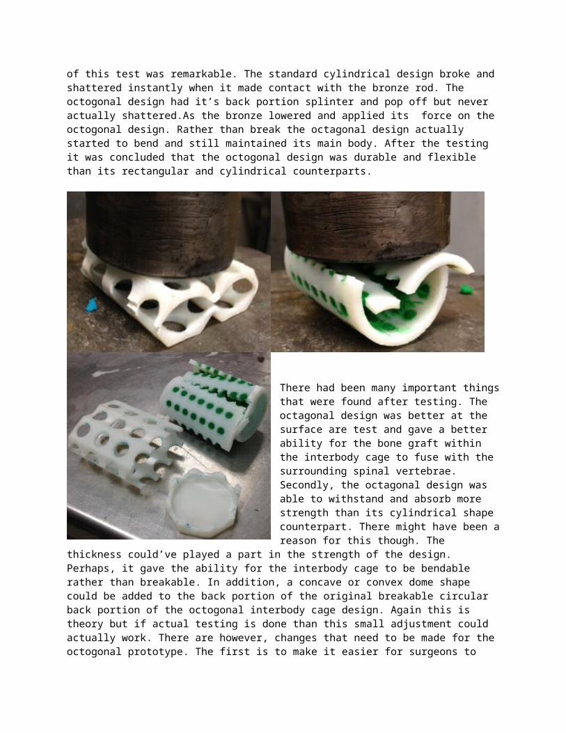
The second test compared the octagonal design with the cylindrical design. In this test there was a device that a had a bronze rod. This bronze rod moved with a lever and crank. The whole point of this bronze rod was to make contact with the different prototypes and make an attempt to break it. The whole purpose of this was the same as the first stress test. A comparison to see if the octagonal design did better
than the cylindrical design needed to be assessed. The outcome of this test was remarkable. The standard cylindrical design broke and shattered instantly when it made contact with the bronze rod. The octogonal design had it’s back portion splinter and pop off but never actually shattered.As the bronze lowered and applied its force on the octogonal design. Rather than break the octagonal design actually started to bend and still maintained its main body. After the testing it was concluded that the octogonal design was durable and flexible than its rectangular and cylindrical counterparts.

There had been many important things that were found after testing. The octagonal design was better at the surface are test and gave a better ability for the bone graft within the interbody cage to fuse with the surrounding spinal vertebrae. Secondly, the octagonal design was able to withstand and absorb more strength than its cylindrical shape counterpart. There might have been a reason for this though. The thickness could’ve played a part in the strength of the design. Perhaps, it gave the ability for the interbody cage to be bendable rather
than breakable. In addition, a concave or convex dome shape could be added to the back portion of the original breakable circular back portion of the octogonal interbody cage design. Again this is theory but if actual testing is done than this small adjustment could actually work. There are however, changes that need to be made for the octogonal prototype. The first is to make it easier for surgeons to drill octagonal shapes through the spinal vertebrae (Most drills are circular). Lastly there has to be a way to prevent further migration of the interbody cage.
In the future there are 3 main tests that can be achieved. First is repeating the same tests that were conducted but with different materials such as carbon fiber and titanium and find out how well these materials do compared to each other. After this the octogonal prototype with the different types of materials can be put into a living organism and be tested for biocompatibility. Finally, ridges can be added to the prototype to resemble an actual interbody cage and prevent migration.
Overall our group believes that the octogonal prototype did better and performed better on the tests that were conducted against the traditional rectangular and cylindrical designed interbody cages. However, further testing and adjustments have to be made for the octogonal designs. After testing and
adjustments are made this octogonal prototype can be turned into an actual working device.
Works Cited:
F. Ullrich, Peter, MD. "Posterior Lumbar Interbody Fusion (PLIF) Surgery."
Spine-Health. N.p., 09 Aug. 2009. Web. Apr. 2013
.<http://www.spine-health.com/treatment/spinal-fusion/posterior-lumbar-interbody-
fusion-plif-surgery>
"Interbody Fusion." SpineMD.com. Virginia Spine Institute, n.d. Web. Apr.
2013. <http://www.spinemd.com/operative-treatments/interbody-fusion-reston-
va.php>.
Ogiela, Denis, MD. "Spinal Fusion." U.S National Library of Medicine. U.S.
National Library of Medicine, 6 May 2012. Web. May 2013.
<http://www.nlm.nih.gov/medlineplus/ency/article/002968.htm>.
Pal Singh, Arun. "How Does Bone Fracture Healing Occur!" Bone and Spine.
Bone and Spine, 20 May 2007. Web. Apr. 2013.
<http://boneandspine.com/trauma/bone-fracture-healing-occur/>.
Patel, Atu. "Result Filters." National Center for Biotechnology Information.
U.S. National Library of Medicine, Oct. 2000. Web. Apr. 2013.
<http://www.ncbi.nlm.nih.gov/pubmed/12897467>.
Rodts, Gerald, MD. "What Should I Know about Lumbar Spinal Fusion?"
SpineUniverse. SpineUniverse, 19 May 2010. Web. May 2013.
<http://www.spineuniverse.com/treatments/surgery/what-should-know-about-
lumbar-spinal-fusion>.