Interactive Drafting Por Diego
493
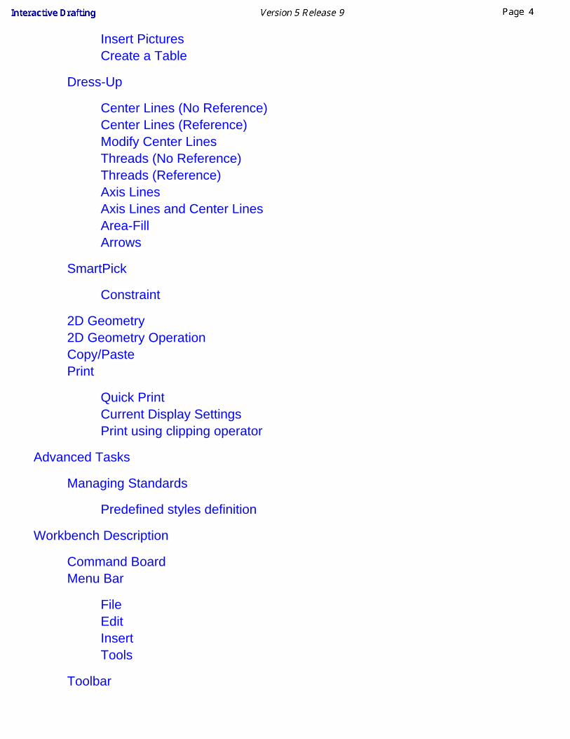
Interactive Drafting Preface Using This Documentation Where to Find More Information What's New Getting Started Workbench New View Rectangles Corners Lines Translate Lines Circles Dimensions Annotations Basic Tasks Using Tools Set As Default Use default Values Sheet Defining the Sheet Modifying the Sheet Deleting the Sheet Creating a Frame Title Block Views Views View Plane Folding Lines Multi-Projection Views
Transcript of Interactive Drafting Por Diego

Interactive Drafting
Preface
Using This DocumentationWhere to Find More Information
What's NewGetting Started
WorkbenchNew ViewRectanglesCornersLinesTranslate LinesCirclesDimensionsAnnotations
Basic Tasks
Using ToolsSet As DefaultUse default ValuesSheet
Defining the SheetModifying the SheetDeleting the SheetCreating a Frame Title Block
Views
ViewsView PlaneFolding LinesMulti-Projection Views

Reframing a View
2D Component
Before you BeginCreating a 2D ComponentRe-Using a 2D ComponentCreating a Component CatalogRe-using a Component from CatalogExplode a Component
Dimensions
Before You BeginDimensionsHalf-DimensionsAngle DimensionsDimension TypeInterrupting Extension LineDimension Line LocationDimension Value Text PositionText Before/AfterDimension Overrun/BlankingCoordinate DimensionsCumulated DimensionsStacked DimensionsExplicit DimensionsHoles Dimensions tableCoordinates Points TableChamfer DimensionsThread DimensionsLining up (Free Space)Lining up (Reference)Datum FeatureModify Datum FeatureGeometrical ToleranceModify Geometrical ToleranceDimension ConstraintsRelations Between Dimensional ConstraintsEdit/Search dimension status
Properties

Editing View PropertiesFeatureGraphicAnnotation FontTextDimension TextsDimension ValueDimension ToleranceDimension Extension LineDimension LineEditing 2D Component Instance Properties
Constraints
Before you BeginGeometric ConstraintsConstraints Between 2D and Generated Elements
Annotations
Before You BeginCreating a Free TextAssociated TextAssociative Existing TextText with LeaderLeader Added to Existing TextFrame and sub frameAdd Attribute Link to TextReplicate TextCopy Graphical PropertiesDatum TargetModify Datum TargetBalloonModify BalloonBalloon on Generated ViewsRoughness SymbolWelding SymbolGeometry WeldFind/Replace TextPositioningEdit query link panel
Insert PicturesCreate a Table
Dress-Up
Center Lines (No Reference)Center Lines (Reference)Modify Center LinesThreads (No Reference)Threads (Reference)Axis LinesAxis Lines and Center LinesArea-FillArrows
SmartPick
Constraint
2D Geometry2D Geometry OperationCopy/PastePrint
Quick PrintCurrent Display SettingsPrint using clipping operator
Advanced Tasks
Managing Standards
Predefined styles definition
Workbench Description
Command BoardMenu Bar
FileEditInsertTools
Toolbar

Geometry Creation ToolbarTransformations ToolbarAnnotations ToolbarDress-Up ToolbarDimensions ToolbarConstraints ToolbarText Properties ToolbarGraphic Properties ToolbarDimensions Properties ToolbarTools ToolbarUse Defaults ToolbarViews Toolbar
Customizing
General SettingsDimension CreationGeometry and Dimension GenerationGeometry CreationView and Sheet LayoutManipulatorsAnnotations Administration Settings
GlossaryIndex
PrefaceVersion 5 Interactive Drafting is a new generation product that addresses 2D designand drawing production requirements.
Interactive Drafting is a highly productive, intuitive drafting system that can be used ina standalone 2D CAD environment within a backbone system. It also expands theGenerative Drafting product with both integrated 2D interactive functionality and anadvanced production environment for the dress-up and annotation of drawings. Thisprovides an easy and smooth evolution from 2D to 3D-based design methodologies.
Complementing an existing Version 4 installation, Interactive Drafting benefits fromupward compatibility with Version 4, making it possible to browse or complete inVersion 5 drawings started with Version 4.
The Interactive Drafting user's guide has been designed to show you how to createdrawings from various complexities. There are several ways of creating a drawing andthis documentation aims at illustrating the several stages of creation you mayencounter.
Using This DocumentationWhere to Find More Information
Using This DocumentationThis User's Guide is intended for users who needs to become quickly familiar withInteractive Drafting Version 5 product.Before reading it, the user should be familiar with basic Version 5 concepts such asdocument windows, standard and view toolbars.
To get the most out of this guide, we suggest that you start reading and performing thestep-by-step tutorial Getting Started and the Workbench Description to find your wayaround the Drafting. The Getting Started tutorial will show you how to create a basicdrawing from scratch.
The next sections deal with the handling of drawing, then the creation and modificationof various types of features you will need to activate a complex drawing. This guidealso presents other Interactive Design capabilities allowing you to design complexparts. You may also want to take a look at the sections describing the InteractiveDrafting menus and toolbars at the end of the guide.

Where to Find More InformationPrior to reading this book, we recommend that you read
Infrastructure User's guide that describes generic capabilities common to allVersion 5 products. It also describes the general layout of V5 and theinteroperability between workbenches.V4 Integration User's Guide that presents interfaces with standard exchangeformats and most of all with V4 data.the Conventions chapter.

What's New?In this section, you will find a list of new or improved features documented in Version 5Release 9 of CATIA Interactive Drafting.Sheets
New: Updating standards
Views
New: Reframing a View2D Components
Enhanced: Re-using a 2D ComponentReplacing the Reference of a 2D Component Instance
Dimensions
New: Specifying the Dimension Value Position
Enhanced: Creating DimensionsSpecifying the Dimension Display ModeOne Symbol DiameterRadius/Diameter Switch after CreationRadius Dimension Line to CenterSlanted Extension Lines Dimension Leader Management
Annotations
Enhanced: Creating a Free Text Changing Character Ratio and SpacingMaking Text Superscript or SubscriptSpecifying the Text Display Mode
Enhanced: Creating a TableInserting a view in a table
Dress-up
Enhanced: Creating an Area FillEnhanced: Creating ArrowsEnhanced: Creating a Welding Symbol

Standards
Enhanced: Managing Standards (this task has been moved from the Customizingchapter to the Advanced Tasks chapter)
Tools > Options
New: Administration Settings

Getting StartedBefore getting into the detailed instructions for using Interactive Drafting workbench, the following tutorial aims at giving you afeel of what you can do with the product. It provides a step-by-step scenario showing you how to use key functionalities.The main tasks described in this section are the following:
Entering the Interactive Drafting WorkbenchCreating a New ViewCreating a Rectangle
Creating CornersCreating Lines
Translating LinesCreating Circles
Creating DimensionsCreating Annotations
This step-by-step scenario introduces the basic capabilities of Interactive Drafting. You just need to followthe instructions as you progress along.Before discovering this scenario, you should be familiar with the basic commands common to allworkbenches. These are described in the Basics User's Guide.All together, the tasks should take about 30 minutes to complete.
The final drawing will look like this:
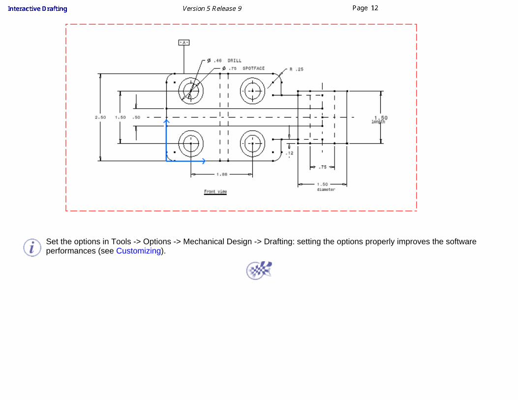
Set the options in Tools -> Options -> Mechanical Design -> Drafting: setting the options properly improves the softwareperformances (see Customizing).

Entering the Interactive DraftingWorkbench
This first task shows you how to enter the Drafting workbench and start a new drawing.
1. Select the File -> New command (or click the New icon).
The New dialog box is displayed, allowing you choosing the type of the document you need.
2. Select Drawing in the List of Types field and click OK.
OR
1. Select the Start -> Mechanical Design commands from the menu bar.
2. Select the Drafting workbench.
OR
1. Select the Tools -> Customize commands (Start Menu tab) and define the Favorites(Drafting) and Accelerator (F12) options as shown below and click the Close switch button.

2. Press F12 key or select the Start -> Drafting F12 commands from the menu bar.
Whatever the dialog you used for entering the Drafting workbench you used, the NewDrawing dialog box is displayed, allowing you choosing the type of Standard, Format,Orientation and scale you need.

3. Select the ISO standard and click the Landscape option.
If you activate the Hide when starting workbench option, the next time you enter theDrafting workbench via Start -> Drafting F12 or by pressing F12 key, the New Drawingdialog box will not appear any more. Still, you will always be able to access this dialog boxby selecting File -> New Drawing command from the menu bar.
4. Click OK.
You can add an unlimited number of customized Standard using CATDrwStandardfiles that you will create and, if needed, modify in the install_root/reffiles/Draftingdirectory. Once created, this Standard will appear in the New Drawing dialog box.For more details on standards, see Managing Standards. Care that any user-definedstandard is based on one of the four international standards (ANSI, ISO,ASME orJIS) as far as basic parameters are concerned.You can create your own Format:
key in the format name in the Format field,use the tab key to access to the Width and Height fields and sets their values.
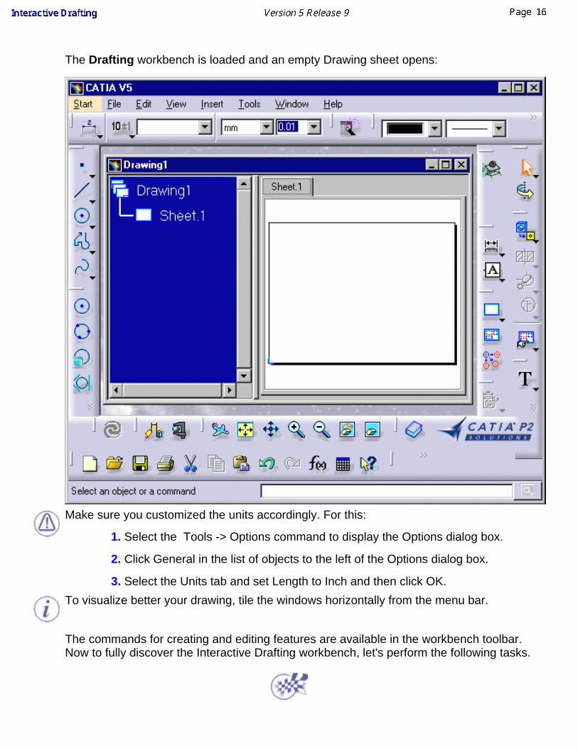
The Drafting workbench is loaded and an empty Drawing sheet opens:
Make sure you customized the units accordingly. For this:
1. Select the Tools -> Options command to display the Options dialog box.
2. Click General in the list of objects to the left of the Options dialog box.
3. Select the Units tab and set Length to Inch and then click OK.To visualize better your drawing, tile the windows horizontally from the menu bar.
The commands for creating and editing features are available in the workbench toolbar.Now to fully discover the Interactive Drafting workbench, let's perform the following tasks.

Creating a New ViewIn this task you will learn how to create a new view in the empty drawing you just openedusing the Drafting Interactive workbench.
1. Click the New View icon and click the Drawing sheet.
2. Click to position the new view. By default, this new view will be a front view.
In the following tasks, you will learn how to draw geometry in the empty view displayedwhich is by default a front view. In other words, you will draw geometry in this empty viewand create both annotations and dimensions on this geometry.
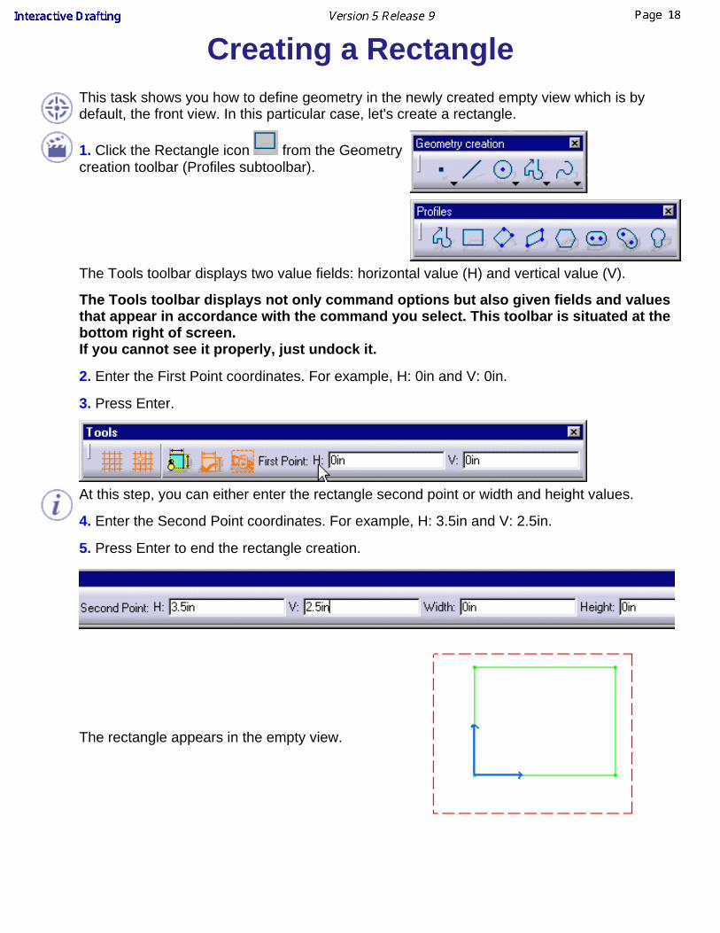
Creating a RectangleThis task shows you how to define geometry in the newly created empty view which is bydefault, the front view. In this particular case, let's create a rectangle.
1. Click the Rectangle icon from the Geometrycreation toolbar (Profiles subtoolbar).
The Tools toolbar displays two value fields: horizontal value (H) and vertical value (V).
The Tools toolbar displays not only command options but also given fields and valuesthat appear in accordance with the command you select. This toolbar is situated at thebottom right of screen.If you cannot see it properly, just undock it.
2. Enter the First Point coordinates. For example, H: 0in and V: 0in.
3. Press Enter.
At this step, you can either enter the rectangle second point or width and height values.
4. Enter the Second Point coordinates. For example, H: 3.5in and V: 2.5in.
5. Press Enter to end the rectangle creation.
The rectangle appears in the empty view.
You can also move the cursor for directly positioning the second point. The correspondingvalues similarly appear on the Tools toolbar.
Note that the grid is not necessarily displayed throughout this documentation. Still, in theGenerative Drafting workbench, the grid is set by default. If you need to display the grid, goto Tools->Options (Drafting/General) and check the Display option.

Creating CornersThis task shows you how to create corners on an existing rectangle bymulti-selecting points.1. Multi-select the rectangleendpoints.
2. Click the Corner icon from the Geometry editiontoolbar (Relimitationssubtoolbar).
The Tools toolbar displays with a Radius field:
3. Enter a radius value in the Tools toolbar. For example, Radius: 0.25in.4. The four corners areautomatically created withthe same radius value.
If you want to create thecorners one after the others,you can also select theCorner icon first and thenclick the geometry.

Creating LinesIn this task you will learn how to create a line.
1. Click the Line icon from theGeometry creation toolbar.
The Tools toolbar displays with the Start Point value fields:
2. Enter the line Start Point coordinates. For example, H: 1.625in and V: 0in.
3. Press Enter.
4. Drag the cursor to the desired location for creating the second line point. Forexample, drag the line end point to the top rectangle horizontal line.
In this particular case, smartpicking is usedfor creating the line. In other words, youwant the line to be parallel with one of therectangle lines.
The parallelism symbol appears asshown here.

Translating LinesThis task shows you how to translate a line. In this particular case, we will also duplicate the lineto be translated.
1. Select an element. For example, a line.
2. Click the Translate icon from the Geometryedition toolbar (Transformations subtoolbar).
The Translation Definition dialog box appears andthe Start Point value fields (H and V) appear in theTools toolbar.
3. The Duplicate mode option (TranslationDefinition dialog box) is activated, by default. If not,activate this mode.
4. Enter the duplicated line Start Point coordinates in the Tools toolbar. For example, H: 1.7in andV:0in.
5. Press Enter.6. Enter the duplicated line End Point coordinates in the Tools toolbar. For example, H: 2in andV:0in.
OR

5. Enter the line Length Value in the TranslationDefinition dialog box. For example, 0.3in.
The Snap Mode is automatically deactivated.
6. Click OK to validate.
7. Once you are satisfied with your operation, clickon the view.The second line is created.
This is the resulting translated line.
A new line is created and translated according to the existing one.
Proceed in the same manner to create the third, fourth, fifth and sixth lines. The process describedabove is valid for any other line to be created with the Translation command in our context.
Select two lines at a time to perform your translation, it is time-saving.

Your final drawing will look like this:
You can also select the Translate icon first and then the geometry to be translated.

Creating CirclesThis task shows you how to create circles and circle centers usingcoordinates.
1. Select the Circle icon from the Geometry creation toolbar.
The Tools toolbar displays circle value fields.
2. Enter the Circle Center coordinates. For example, H: 0.75in and V: 2in.3. Press Enter.
4. Enter the circle radius. For example, R: 0.375in.5. Press Enter.
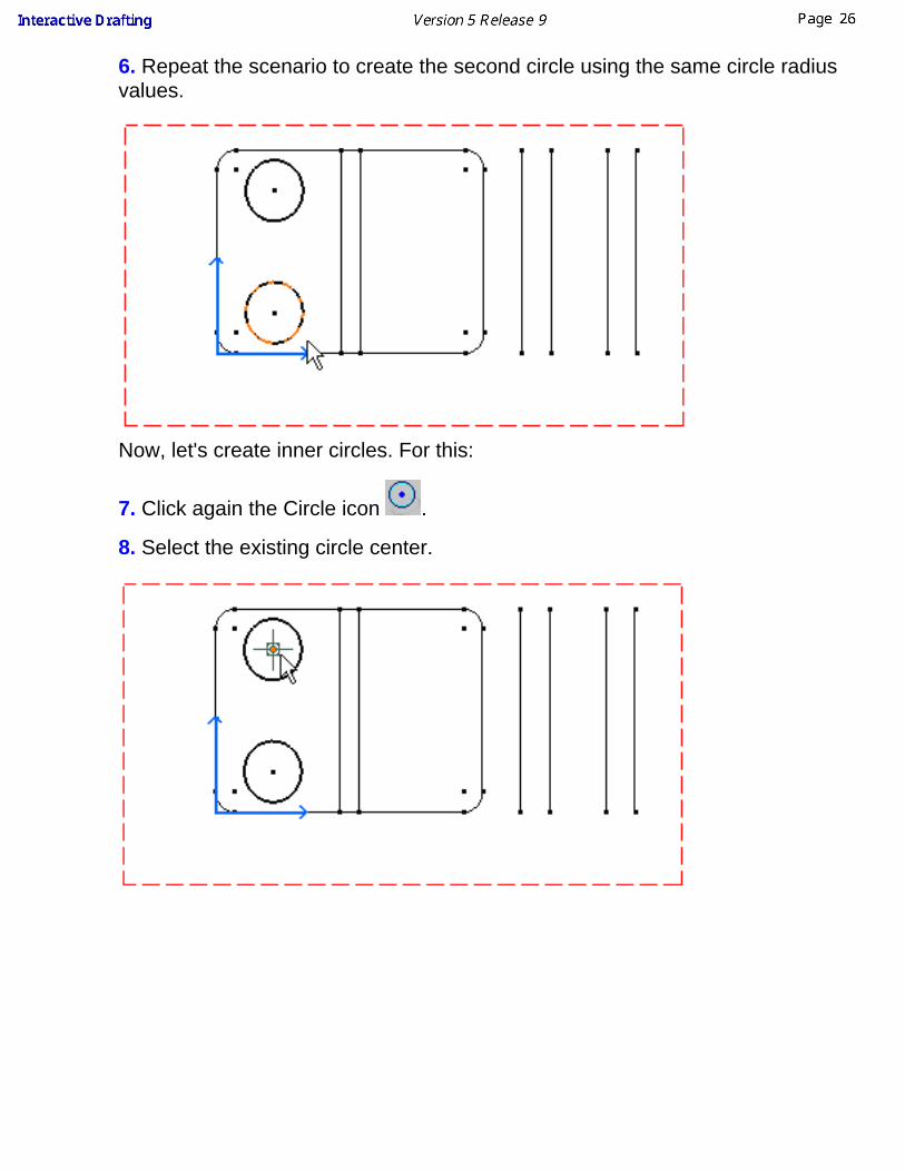
6. Repeat the scenario to create the second circle using the same circle radiusvalues.
Now, let's create inner circles. For this:
7. Click again the Circle icon .
8. Select the existing circle center.

9. Enter the center circle radius.
10. Press Enter.
11. Repeat the scenario to create the second inner circle.
This is what you obtain:
You can also select the geometry to be translated first and then the Translate
command .
You can then translate the circles newly created and get the following result:


Creating DimensionsThis task shows you how to add dimensions to the geometry you previouslycreated.
1. Click the Dimension icon from the Dimensioning toolbar.
2. Click a first element in the view. For example, the rectangle top line.
At this step, a dimension appears (length dimension). This dimension is definedaccording to the element first selected. You can either accept the dimension(click in the free space) or select another element (for creating a distancedimension).
3. Click a second element in the view. For example, the rectangle bottom line.

4. If needed, drag the dimension to the desired location.
At this step, you can apply various modifications to the dimension you arecreating. You can:
modify the dimension overrun/blanking using manipulators or the Ctrlkey to modify only one extension line.add text before or after by double-clicking the dimensionredefine the dimension properties using the required toolbar:

Creating AnnotationsThis task shows you how to add annotations on your drawing. In this particularcase, we will add text to existing 2D elements.1. Click on an icon from theAnnotations toolbar.
For example, click the Text icon
.
2. Click an element.
The text will be positionedaccording to this element.
3. Enter the required text in theText Editor dialog box.
As you type in, the text appears in the graphic Text Editor window.

4. If needed, drag the text to thedesired location.
The annotation will now remain associated to the selected 2D element. In otherwords, each time you move the 2D element, the associated annotation movesaccordingly.

Basic TasksThe basic tasks you will perform in the Interactive Drafting workbench mainlydeal with creating and modifying 2D elements and their related attributes on apredefined sheet. The tasks documented in this section explain and illustrate howto create various kinds of features to obtain a complete CATDrawing document.
You can perform the following basic tasks:
Using ToolsSetting Properties As Default
Using Default ValuesSheetsViews
2D ComponentsDimensionsPropertiesConstraintsAnnotationsDress-UpSmartPick
2D Geometry2D Geometry Operation
Copy/PastePrint
All basic tasks provide links to CATDrawing document samples that you can usefor practicing. When opening a CATDrawing document sample using the httpprotocol, make sure the application associated to this file type is defined on theserver. In other words, in the Internet Explorer address field you must see"http://...".

Using ToolsYou will find here below information on helpful tools for creating any interactive elements.Multi-selection can also be very useful.
Tools ToolbarThe Tools toolbar displays both command options and given fields/values that appear inaccordance with the command you select. This toolbar is situated at the bottom right ofscreen. If you cannot see it properly, just undock it.
The Tools toolbar provides the following options:
Grid
Snap to Point
Analysis Display Mode
Create Constraints (See chapter on Constraints)
Create Detected Constraints (See chapter on Constraints)
Filter Generated Elements
Projected Dimension
Force Dimension on Element
Force to Horizontal Position
Force to Vertical Position
True Length Dimensions
The values of the elements you sketch appear in the Tools toolbar as you move the cursor. Inother words, as you are moving the cursor, the Horizontal (H), Vertical (V), Length (L) and Angle(A) fields display the coordinates corresponding to the cursor position.
You can also use these fields for entering the values of your choice. In the following scenario,you are going to sketch a line by entering values in the appropriate fields.

1. Click the Line icon from the Geometry creation toolbar.
The Tools toolbar displays information on value fields.
2. Enter the coordinates of the First Point and press enter.3. Enter the coordinates of the Second Point and press enter.
OR
3. Enter the length (L) of the line and press enter.4. Enter the value of the angle (A) between the line to be created and the horizontal axis andpress enter.The line is created.Depending on the number of fields available and the way you customized your toolbar,some fields may be truncated. What you need to do is just undock the Tools toolbars.
Grid
The grid will help you draw geometry in given circumstances. For example, the grid will make iteasier to draw profiles requiring parallel lines.
Snap to Point
If activated, this option makes your geometry begin or end on the points of the grid. As you arecreating 2D geometry, points are forced to the intersection points of the grid. Note that thisoption is also available using Tools ->Options ->Drafting (General tab).
1. Create a spline.
In this example, the black spline was created with theSnap to Point option activated. The points are on thegrid.
Conversely, the highlighted spline was created with theoption deactivated.

You can use autodetection even if this option is on.
In the case of dimensions and annotations, even though the Snap to Point option remains on(red-colored), you can temporarily de-activate the functionality. For this, press the Shift buttonwhile you move the dimension or annotation.
Analysis Display Mode
This option allows visualizing the colors assigned to the different types of dimensions.
These displayed colors correspond to the colors customized in the Options dialog box. Tomodify these colors, go to Tools -> Options -> Mechanical Design -> Drafting (Dimension tab).Then check Activate analysis display mode and, if needed, click the Types and colors switchbutton to assign the desired color(s) to the desired dimension types.
Projected/Forced/True Length Dimension
Projected Dimension (according to the cursorposition)
Force Dimension on Element
Force to Horizontal Position Force to Vertical Position

True Length Dimensions
Remember that as you create the dimension in one mode, you can use the contextual menuand select another mode.
Differentiating Between 2D Elements and Elements Generatedfrom the 3DYou can differentiate 2D elements (Interactive workbench) from generated elements(Generative workbench) within the same view. This can proove very helpful when you need toadd purely interactive elements onto generated views.Open the GenDrafting_part.CATDrawing document. Create a text with a leader on an activeview.
1. Click the Filter Generated Elements icon fromthe Tools toolbar.The generated elements appear in grey.
2. Create a 2D element. For example, create a textwith leader.The 2D elements appear in black.
This command is active provided you installed Generative Drafting license.
Make the Most of Multi-selectionWhen you need to create and/or modify an element, you can either select the element or thecommand first. Multi-selection can only be used for given commands. You are therefore allowedto select element(s) before these given commands.

Open the Brackets_views06.CATDrawing document.
1. Multi-select 2D elements. For example, four circles.
2. Click the desired command. For example, the Threads
icon .
Four threads are automatically applied to the selectedcircles.

Setting Properties As DefaultThis task shows you how to set graphical properties to elements to be created.
Open the Brackets_views03.CATDrawing document.
1. Right-click the element to be set as defaultwhen creating other elements of the samekind. For example, Text01.
2. Select the Set as default option from thecontextual menu.
The options displayed in the Propertiestoolbars (top of the screen) are automaticallyupdated and display the propertiescorresponding to the selected element.
3. Select the Only User Default option fromthe style toolbar to specify that from now on,you do not want to use the options in theProperties toolbar as defaults.
The fields in the Properties toolbars becomegray colored and therefore cannot bemodified.
4. Create a new text. For example, Text02.
The new text is automatically assigned thesame graphical properties as the text set asdefault.
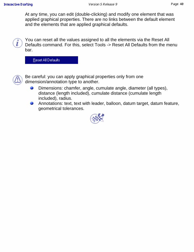
At any time, you can edit (double-clicking) and modify one element that wasapplied graphical properties. There are no links between the default elementand the elements that are applied graphical defaults.
You can reset all the values assigned to all the elements via the Reset AllDefaults command. For this, select Tools -> Reset All Defaults from the menubar.
Be careful: you can apply graphical properties only from onedimension/annotation type to another.
Dimensions: chamfer, angle, cumulate angle, diameter (all types),distance (length included), cumulate distance (cumulate lengthincluded), radius.Annotations: text, text with leader, balloon, datum target, datum feature,geometrical tolerances.

Using Default ValuesThis task shows you how to use default values. To understand how to set as default an element properties, see Setting As Default Properties.
1. Create the following text, see Creating a Free Text
2. Select properties in the contextual menu (right-click). In font tab, select the bold italic style and in text tab increase the line spacing to 5 mm.

Click ok. The text looks like this
3. Select the Set as default option from the contextual menu.
The values you set are stored.
Click in the drawing to finish the creation.
4. Select the font SSS1 in the Text Properties Toolbar.
5. Select the Catia Default Properties option from the style toolbar to specify that from now, you want to use the software default options apart fromthe Text Properties toolbar settings.
6. Create a new text.

The line spacing is equal to 0 mm and the font is regular.
Catia Default Properties (that is to say the settings defined in the Text Properties toolbar) are taken into account.
7. Select the User Default Properties option from the style toolbar to specify that you want to use the options set by default (see step 2.) apart fromoptions set in the Text Properties toolbar.
8. Create a new text.
In this example you have modified the font in the Text Properties toolbar, the new text will be created with default settings (see step 2.) apart fromthe font.
User Default Properties (that is to say the settings set as default, apart from those defined in the Text Properties toolbar) are taken intoaccount.

9. Select the Only User Default Properties option from the style toolbar to specify that you want to use only the options set by default (see step 2.).
10. Create a new text.
Only User Default Properties (that is to say only the settings set as default) are taken into account.
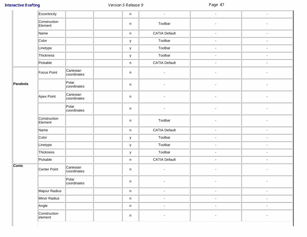
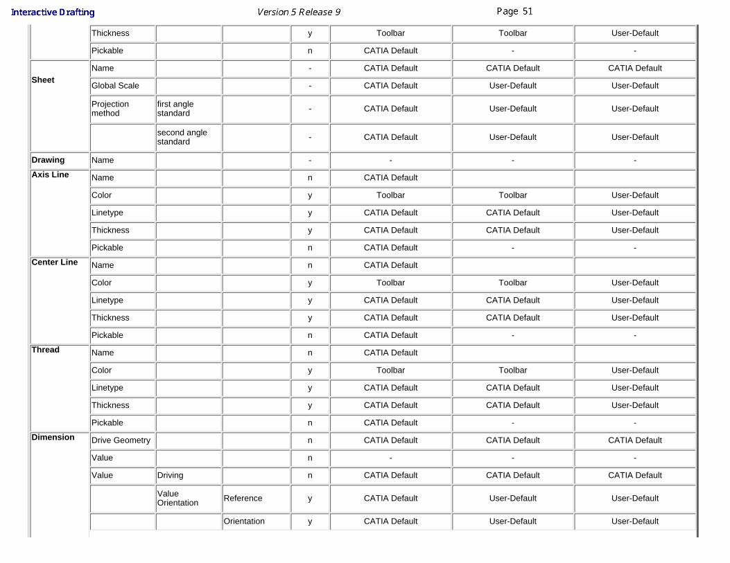
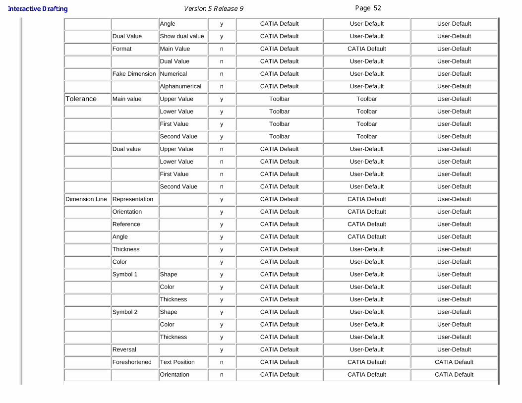
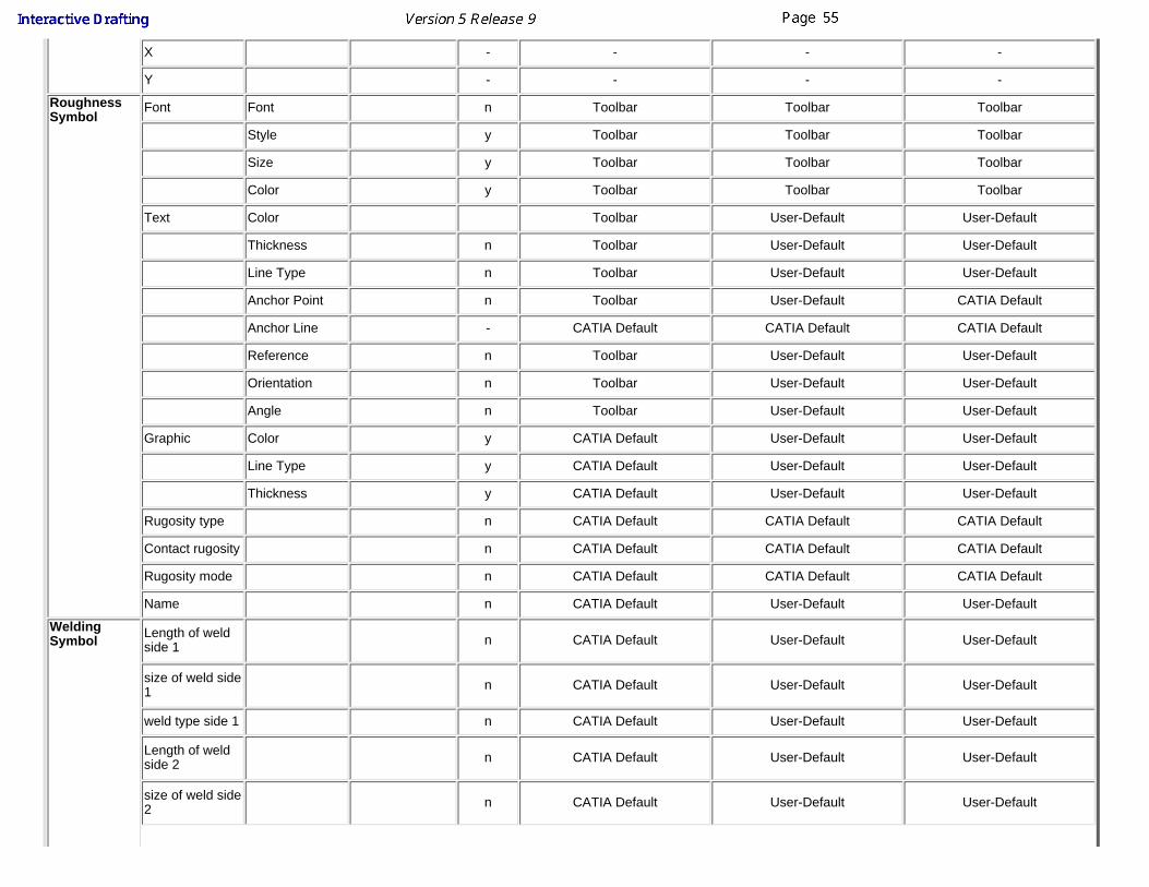
You will find here below a table with all the object that can be taken into account when using the Painter or copying the object format from one object toanother.
Object Properties
Are these taken into account?Painter CATIA Default Properties User Default Properties Only User Default
Properties
Spline
Name n CATIA Default - -
Color y Toolbar - -
Linetype y Toolbar - -

Thickness y Toolbar - -
Pickable n CATIA Default - -
Line
Name n CATIA Default - -
Color y Toolbar - -
Linetype y Toolbar - -
Thickness y Toolbar - -
Pickable n CATIA Default - -
End Point 1 Cartesiancoordinates n - - -
Polarcoordinates n - - -
End Point 2 Cartesiancoordinates n - - -
Polarcoordinates n - - -
Length n - - -
Angle n - - -
Constructionelement n Toolbar - -
Point
Cartesiancoordinates n - - -
Polarcoordinates n - - -
Constructionelement n Toolbar - -
Name n CATIA Default - -
Color y Toolbar - -
Symbol y Toolbar - -
Pickable n CATIA Default - -
Circle
Center Point Cartesiancoordinates n - - -

Polarcoordinates n - -
Radius n - - -
ConstructionElement n Toolbar - -
Name n CATIA Default - -
Color y Toolbar - -
Linetype y Toolbar - -
Thickness y Toolbar - -
Pickable n CATIA Default - -
Ellipse
Center Point Cartesiancoordinates n - - -
Polarcoordinates n - - -
Majour Radius n - - -
Minor Radius n - - -
Angle n - - -
Constructionelement n Toolbar - -
Name n CATIA Default - -
Color y Toolbar - -
Linetype y Toolbar - -
Thickness y Toolbar - -
Pickable n CATIA Default - -
HyperbolFocus Point Cartesian
coordinates n - - -
Polarcoordinates n - - -
Center Point Cartesiancoordinates n - - -
Polarcoordinates n - - -
Excentricity n - - -
ConstructionElement n Toolbar - -
Name n CATIA Default - -
Color y Toolbar - -
Linetype y Toolbar - -
Thickness y Toolbar - -
Pickable n CATIA Default - -
Parabola
Focus Point Cartesiancoordinates n - - -
Polarcoordinates n - - -
Apex Point Cartesiancoordinates n - - -
Polarcoordinates n - - -
ConstructionElement n Toolbar - -
Name n CATIA Default - -
Color y Toolbar - -
Linetype y Toolbar - -
Thickness y Toolbar - -
Pickable n CATIA Default - -
ConicCenter Point Cartesian
coordinates n - - -
Polarcoordinates n - - -
Majour Radius n - - -
Minor Radius n - - -
Angle n - - -
Constructionelement n - - -

Name n - - -
Color y - - -
Linetype y - - -
Thickness y - - -
Pickable n - - -
Text String n - - -
Name n CATIA Default
Font Font y Toolbar Toolbar User-Default
Style y Toolbar Toolbar User-Default
Size y Toolbar Toolbar User-Default
UnderLine y Toolbar Toolbar User-Default
Color y Toolbar Toolbar User-Default
Ratio y CATIA Default User-Default User-Default
Strikethrough y Toolbar Toolbar User-Default
Superscript y Toolbar Toolbar User-Default
Subscript y Toolbar Toolbar User-Default
Overline y Toolbar Toolbar User-Default
Text Frame y Toolbar Toolbar User-Default
Color y Toolbar Toolbar User-Default
Thickness y Toolbar Toolbar User-Default
Line Type y Toolbar Toolbar User-Default
Anchor point y Toolbar Toolbar User-Default
X y Toolbar Toolbar User-Default
Y y Toolbar Toolbar User-Default
Anchor Line y CATIA Default CATIA Default User-Default
Line Spacing y CATIA Default User-Default User-Default
Line SpacingMode y CATIA Default User-Default User-Default
Justification y Toolbar Toolbar User-Default

Word wrap y CATIA Default CATIA Default User-Default
Reference y CATIA Default User-Default User-Default
Orientation y CATIA Default User-Default User-Default
Angle y CATIA Default User-Default User-Default
Mirroring y CATIA Default User-Default User-Default
Auto flip y CATIA Default User-Default User-Default
Graphic Thickness y Toolbar Toolbar User-Default
Linetype y Toolbar Toolbar User-Default
Color y Toolbar Toolbar User-Default
Pickable n CATIA Default - Text withleader
String n - - -
Name n CATIA Default
Font Font y Toolbar Toolbar User-Default
Style y Toolbar Toolbar User-Default
Size y Toolbar Toolbar User-Default
UnderLine y Toolbar Toolbar User-Default
Color y Toolbar Toolbar User-Default
Ratio y CATIA Default User-Default User-Default
Strikethrough y Toolbar Toolbar User-Default
Superscript y Toolbar Toolbar User-Default
Subscript y Toolbar Toolbar User-Default
Overline y Toolbar Toolbar User-Default
Text Frame y Toolbar Toolbar User-Default
Color y Toolbar Toolbar User-Default
Thickness y Toolbar Toolbar User-Default
Line Type y Toolbar Toolbar User-Default
Anchor point y Toolbar Toolbar User-Default
Anchor Line y CATIA Default User-Default User-Default
Line Spacing y CATIA Default User-Default User-Default

Line SpacingMode y CATIA Default User-Default User-Default
Justification y Toolbar User-Default User-Default
Word wrap y CATIA Default User-Default User-Default
Reference y CATIA Default User-Default User-Default
Orientation y CATIA Default User-Default User-Default
Angle y CATIA Default User-Default User-Default
Mirroring y CATIA Default User-Default User-Default
Auto flip y CATIA Default User-Default User-Default
Graphic Color y Toolbar Toolbar User-Default
Linetype y Toolbar Toolbar User-Default
Thickness y Toolbar Toolbar User-Default
Pickable n CATIA Default - User-Default
View Scale n CATIA Default User-Default User-Default
Rotation n CATIA Default User-Default User-Default
View Name Prefix n CATIA Default CATIA Default CATIA Default
Ident n CATIA Default CATIA Default CATIA Default
Suffix n CATIA Default CATIA Default CATIA Default
Dressup Hidden Lines n CATIA Default CATIA Default CATIA Default
Axis n CATIA Default User-Default User-Default
Center Line n CATIA Default User-Default User-Default
Thread n CATIA Default User-Default User-Default
Boundary fillet n CATIA Default CATIA Default CATIA Default
Uncut spec CATIA Default CATIA Default CATIA Default
3D Wireframe CATIA Default CATIA Default CATIA Default
Visualizationand Behaviour
Display ViewFrame n CATIA Default User-Default User-Default
Lock View n CATIA Default User-Default User-Default
Color y Toolbar Toolbar User-Default
Linetype y Toolbar Toolbar User-Default
Thickness y Toolbar Toolbar User-Default
Pickable n CATIA Default - -
Sheet
Name - CATIA Default CATIA Default CATIA Default
Global Scale - CATIA Default User-Default User-Default
Projectionmethod
first anglestandard - CATIA Default User-Default User-Default
second anglestandard - CATIA Default User-Default User-Default
Drawing Name - - - -
Axis Line Name n CATIA Default
Color y Toolbar Toolbar User-Default
Linetype y CATIA Default CATIA Default User-Default
Thickness y CATIA Default CATIA Default User-Default
Pickable n CATIA Default - -
Center Line Name n CATIA Default
Color y Toolbar Toolbar User-Default
Linetype y CATIA Default CATIA Default User-Default
Thickness y CATIA Default CATIA Default User-Default
Pickable n CATIA Default - -
Thread Name n CATIA Default
Color y Toolbar Toolbar User-Default
Linetype y CATIA Default CATIA Default User-Default
Thickness y CATIA Default CATIA Default User-Default
Pickable n CATIA Default - -
Dimension Drive Geometry n CATIA Default CATIA Default CATIA Default
Value n - - -
Value Driving n CATIA Default CATIA Default CATIA Default
ValueOrientation Reference y CATIA Default User-Default User-Default
Orientation y CATIA Default User-Default User-Default
Angle y CATIA Default User-Default User-Default
Dual Value Show dual value y CATIA Default User-Default User-Default
Format Main Value n CATIA Default CATIA Default User-Default
Dual Value n CATIA Default User-Default User-Default
Fake Dimension Numerical n CATIA Default User-Default User-Default
Alphanumerical n CATIA Default User-Default User-Default
Tolerance Main value Upper Value y Toolbar Toolbar User-Default
Lower Value y Toolbar Toolbar User-Default
First Value y Toolbar Toolbar User-Default
Second Value y Toolbar Toolbar User-Default
Dual value Upper Value n CATIA Default User-Default User-Default
Lower Value n CATIA Default User-Default User-Default
First Value n CATIA Default User-Default User-Default
Second Value n CATIA Default User-Default User-Default
Dimension Line Representation y CATIA Default CATIA Default User-Default
Orientation y CATIA Default CATIA Default User-Default
Reference y CATIA Default CATIA Default User-Default
Angle y CATIA Default CATIA Default User-Default
Thickness y CATIA Default User-Default User-Default
Color y CATIA Default User-Default User-Default
Symbol 1 Shape y CATIA Default User-Default User-Default
Color y CATIA Default User-Default User-Default
Thickness y CATIA Default User-Default User-Default
Symbol 2 Shape y CATIA Default User-Default User-Default
Color y CATIA Default User-Default User-Default
Thickness y CATIA Default User-Default User-Default
Reversal y CATIA Default User-Default User-Default
Foreshortened Text Position n CATIA Default CATIA Default CATIA Default
Orientation n CATIA Default CATIA Default CATIA Default

Angle n CATIA Default CATIA Default CATIA Default
Ratio n CATIA Default CATIA Default CATIA Default
Point scale n CATIA Default CATIA Default CATIA Default
Extension Line Extremities Overrun n CATIA Default User-Default User-Default
Blanking n CATIA Default User-Default User-Default
Color y CATIA Default User-Default User-Default
Thickness y CATIA Default User-Default User-Default
Display firstextension line y CATIA Default User-Default User-Default
Display secondextension line y CATIA Default User-Default User-Default
Funnel Height n CATIA Default User-Default User-Default
Angle n CATIA Default User-Default User-Default
Width n CATIA Default User-Default User-Default
Funnel mode n CATIA Default User-Default User-Default
Funnel side n CATIA Default User-Default User-Default
Dimension Text Prefix - Sufix Symbol y Toolbar Toolbar User-Default
Main Value y Toolbar Toolbar User-Default
Associated texts Main Value y CATIA Default User-Default
Dual Value n CATIA Default User-Default
Dimension scoreoptions Main y CATIA Default User-Default
Dual y CATIA Default User-Default
Dimensionframe options Element y CATIA Default User-Default
Group y CATIA Default User-Default
Font Font n Toolbar Toolbar User-Default
Style y Toolbar Toolbar User-Default
Size y Toolbar Toolbar User-Default
UnderLine n Toolbar Toolbar User-Default
Color y Toolbar Toolbar User-Default

Strikethrough n Toolbar Toolbar User-Default
Overline n Toolbar Toolbar User-Default
Text Frame y Toolbar Toolbar User-Default
Color y Toolbar Toolbar User-Default
Thickness y Toolbar Toolbar User-Default
Line Type y Toolbar Toolbar User-Default
Graphic Color y CATIA Default User-Default User-Default
Linetype y CATIA Default User-Default User-Default
Thickness y CATIA Default User-Default User-Default
Pickable y CATIA Default - -
Area Fill Name n CATIA Default
Color - CATIA Default User-Default User-Default
Linetype - Toolbar User-Default User-Default
Thickness - Toolbar User-Default User-Default
Pickable n CATIA Default User-Default User-Default
Type Dotting Pitch y Toolbar CATIA Default User-Default
Zigzag y Toolbar Toolbar User-Default
Color y Toolbar Toolbar User-Default
Coloring Color y Toolbar Toolbar User-Default
Hatching Number ofhatching y Toolbar Toolbar User-Default
n-th hatchingproperties y Toolbar Toolbar User-Default
2DComponent
Name n - - -
Color y CATIA Default - -
Linetype y CATIA Default - -
Thickness y CATIA Default - -
Pickable n CATIA Default -
Angle n CATIA Default - -
Scale n CATIA Default - -
X - - - -
Y - - - -
RoughnessSymbol
Font Font n Toolbar Toolbar Toolbar
Style y Toolbar Toolbar Toolbar
Size y Toolbar Toolbar Toolbar
Color y Toolbar Toolbar Toolbar
Text Color Toolbar User-Default User-Default
Thickness n Toolbar User-Default User-Default
Line Type n Toolbar User-Default User-Default
Anchor Point n Toolbar User-Default CATIA Default
Anchor Line - CATIA Default CATIA Default CATIA Default
Reference n Toolbar User-Default User-Default
Orientation n Toolbar User-Default User-Default
Angle n Toolbar User-Default User-Default
Graphic Color y CATIA Default User-Default User-Default
Line Type y CATIA Default User-Default User-Default
Thickness y CATIA Default User-Default User-Default
Rugosity type n CATIA Default CATIA Default CATIA Default
Contact rugosity n CATIA Default CATIA Default CATIA Default
Rugosity mode n CATIA Default CATIA Default CATIA Default
Name n CATIA Default User-Default User-Default
WeldingSymbol Length of weld
side 1 n CATIA Default User-Default User-Default
size of weld side1 n CATIA Default User-Default User-Default
weld type side 1 n CATIA Default User-Default User-Default
Length of weldside 2 n CATIA Default User-Default User-Default
size of weld side2 n CATIA Default User-Default User-Default

weld type side 2 n CATIA Default User-Default User-Default
field weldsymbol n CATIA Default User-Default User-Default
weld-all-aroundsymbol n CATIA Default User-Default User-Default
Font Font y Toolbar User-Default User-Default
Style y Toolbar Toolbar User-Default
Size y Toolbar Toolbar User-Default
Color y Toolbar Toolbar User-Default
Text Frame color Toolbar Toolbar User-Default
FrameThickness y Toolbar Toolbar User-Default
Frame LineType y Toolbar Toolbar User-Default
Reference n CATIA Default User-Default User-Default
Orientation - CATIA Default User-Default User-Default
Angle n CATIA Default User-Default User-Default
Graphic Color y Toolbar Toolbar User-Default
Line Type y Toolbar Toolbar User-Default
Thickness y Toolbar Toolbar User-Default
Name n CATIA Default User-Default User-Default
BalloonString n - - -
Font Font n Toolbar Toolbar User-Default
Style n Toolbar Toolbar User-Default
Size n Toolbar Toolbar User-Default
Color n Toolbar Toolbar User-Default
Text Frame color y CATIA Default Toolbar User-Default
Thickness y Toolbar Toolbar User-Default
Frame LineType y Toolbar Toolbar User-Default
Anchor Point n Toolbar Toolbar Toolbar

Anchor Line n CATIA Default CATIA Default Toolbar
Reference n CATIA Default CATIA Default CATIA Default
Orientation n CATIA Default CATIA Default CATIA Default
Angle n CATIA Default CATIA Default CATIA Default
Graphic Color y CATIA Default Toolbar User-Default
Line Type y Toolbar Toolbar User-Default
Thickness y Toolbar Toolbar User-Default
Name n CATIA Default User-Default User-Default
DatumFeature String n - - -
Name n CATIA Default User-Default User-Default
Font Font n Toolbar Toolbar User-Default
Style n Toolbar Toolbar User-Default
Size n Toolbar Toolbar User-Default
Color n Toolbar Toolbar User-Default
Text Frame color y CATIA Default User-Default User-Default
Thickness y Toolbar Toolbar User-Default
Frame LineType y Toolbar Toolbar User-Default
Anchor Point n Toolbar Toolbar User-Default
Anchor Line n CATIA Default CATIA Default User-Default
Reference n CATIA Default User-Default User-Default
Orientation n CATIA Default CATIA Default CATIA Default
Angle n CATIA Default CATIA Default CATIA Default
Graphic Color y CATIA Default User-Default User-Default
Line Type y Toolbar Toolbar User-Default
Thickness y Toolbar Toolbar User-Default
Datum TargetString n - - -
Diameter y - CATIA Default CATIA Default
Name n CATIA Default User-Default User-Default

Font Font y CATIA Default User-Default User-Default
Style y CATIA Default User-Default User-Default
Size y CATIA Default User-Default User-Default
Color y CATIA Default User-Default User-Default
Text Frame color y CATIA Default User-Default User-Default
Thickness y CATIA Default User-Default User-Default
Frame LineType y CATIA Default User-Default User-Default
Anchor Point y CATIA Default User-Default Toolbar
Anchor Line n CATIA Default CATIA Default CATIA Default
Reference n CATIA Default User-Default User-Default
Orientation n CATIA Default CATIA Default CATIA Default
Angle n CATIA Default CATIA Default CATIA Default
Graphic Color y CATIA Default User-Default User-Default
Line Type y CATIA Default User-Default User-Default
Thickness y CATIA Default User-Default User-Default
GeometricalTolerance Name n CATIA Default - -
PrimaryGeometricCharacteristic
n - - -
Diameter Zone n - - -
Tolerance Value n - - -
toleranceFeature Modifier n - - -
Primary DatumText n - - -
Primary DatumFeature Modifier n - - -
SecondaryDatum Text n - - -

SecondaryDatum FeatureModifier
n - - -
Tertiary DatumText n - - -
Tertiary DatumFeature Modifier n - - -
Font Font n Toolbar - -
Style n Toolbar - -
Size n Toolbar - -
Color n Toolbar - -
Text Frame color y CATIA Default - -
Thickness y CATIA Default - -
Frame LineType y CATIA Default - -
Anchor Point n CATIA Default - -
Anchor Line n CATIA Default - -
Reference n CATIA Default - -
Orientation n CATIA Default - -
Angle n CATIA Default - -
Graphic Color y CATIA Default - -
Line Type y CATIA Default - -
Thickness y CATIA Default - -

SheetsThe Interactive Drafting workbench provides a simple method to manipulate asheet.
A sheet contains:a main view: a view which supports the geometry directly created in the sheeta background view: a view dedicated to frames and title blocksinteractive or generated views
Define the sheet
Define the sheet using commands and dialog boxes.Modify the sheet
Modify the sheet orientation using the Page Setup dialog box.Delete the sheet
Create a background sheet and insert a frame and a title block into itusing the Frame and Title Block dialog box.
Create a frame title blockInsert a .gif image into a title block.

Defining a SheetThis task will show you how to define a sheet.
For more information about drafting workbench access, see Entering theInteractive Drafting Workbench.
1. Click the New icon or selectFile -> New.
2. Select the Drawing workbench,and click OK.
3. From the New Drawing dialog box,select the ISO standard, and theA0 ISO format.
4. Select the Landscape orientation.
5. Select the 1:1 scale, and then clickOK.

You can create your own format:key in the format name in the Format field,use the tab key to access to the Width and Height fields and setstheir values.
You can add an unlimited number of customized Standard usingCATDrwStandard files that you will create and, if needed, modify in the$OS\resources\standard directory. Once created, this Standard willappear in the New Drawing dialog box. For more details on standards,see chapter Managing standards. Care that any user-defined standard isbased on one of the four international standards (ANSI, ISO,ASME orJIS) as far as basic parameters are concerned.At any time, you can change the standard (which you can update), sheetformat, orientation and/or scale. To do this, select File->Page Setup fromthe menu bar.
If you select a new standard, the value in the Apply on field becomes Allsheets and the new standard is applied to all drawing sheetsannotations.
.

The sheet size depends on the standard type. For example, if youchoose the ISO standard, the sheet will automatically be assigned the A0format type. You can choose another format if you want.
To add a new sheet, click the New Sheet icon . The new sheet
automatically appears as follows:
The Insert Elements into a Sheet dialog box appears. For more details, seeManaging a Background View in the Generative Drafting User's Guide.
Once you have created more than one sheet, to activate one of the sheets,select this sheet from the dialog window.
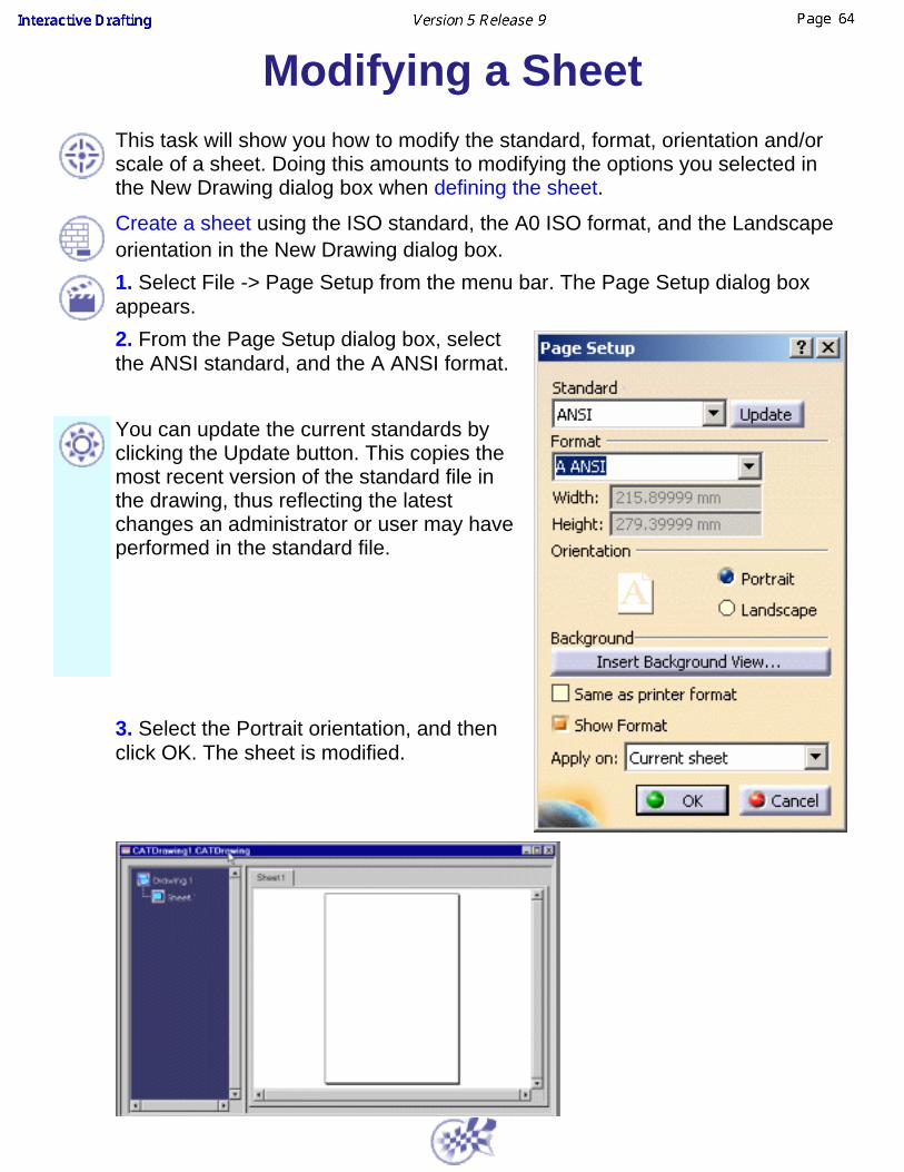
Modifying a SheetThis task will show you how to modify the standard, format, orientation and/orscale of a sheet. Doing this amounts to modifying the options you selected inthe New Drawing dialog box when defining the sheet.
Create a sheet using the ISO standard, the A0 ISO format, and the Landscapeorientation in the New Drawing dialog box.1. Select File -> Page Setup from the menu bar. The Page Setup dialog boxappears.2. From the Page Setup dialog box, selectthe ANSI standard, and the A ANSI format.
You can update the current standards byclicking the Update button. This copies themost recent version of the standard file inthe drawing, thus reflecting the latestchanges an administrator or user may haveperformed in the standard file.
3. Select the Portrait orientation, and thenclick OK. The sheet is modified.

Deleting a SheetThis task will show you how to delete a sheet. When a CATDrawing documentis opened, one sheet is necessarily displayed.You created more than one sheet.
1. Select thesheet from thespecificationtree. Forexample, Sheet2.
2. Right-click theselected sheetand display thecontextualmenu.
3. Select theDelete optionfrom thecontextualmenu.
Sheet 2 isdeleted.
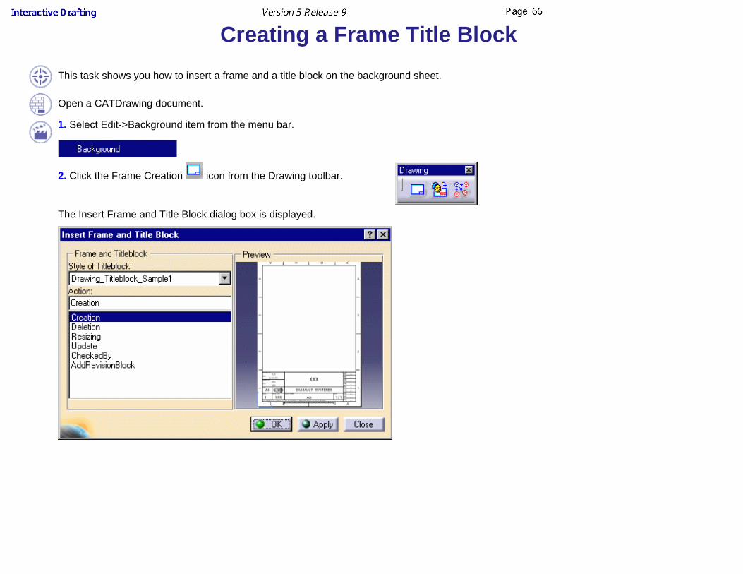
Creating a Frame Title Block This task shows you how to insert a frame and a title block on the background sheet.
Open a CATDrawing document.
1. Select Edit->Background item from the menu bar.
2. Click the Frame Creation icon from the Drawing toolbar.
The Insert Frame and Title Block dialog box is displayed.

you can choose a format in the combo box Format Label.Action Label allows you to:
create the frame and the title block,delete it,resize it (if you change the page format in file -> Page Setup,update frame and title block if the part has been modified,SpecUpdate allows you to complete the field "checked by" and update automatically checking date,add a revision block.
Blank information in the part will be substituted by "XXX" in the drawing.
3. Click OK in the Insert Frame and Title Block dialog box.
You can modify the macro to add actions or create new macros to add specific formats.

ViewsInteractive Drafting elements necessarily need to be positioned in a view. In otherwords, you will first create a view on a sheet and then add 2D geometry, dimensions,annotations and/or dress-up elements in this view.
Create views
Create a front view and then projection views.Define the view plane
Generate geometry in a view by projecting geometry from previouslydefined views.
Create views using folding linesAdd geometry in views using folding lines as an assistant.
Create multi-projection viewsGenerate geometry in a view by projecting geometry from previouslydefined views.
Reframe viewsReframe a view so as to display only part of it.

Creating ViewsThis task will show you how to create views. If the sheet is active, the first viewyou create is by default a front view.
1. Click the New View icon .
2. Click the Drawing window.
A blue axis displays in a red frame. The front view created displays in thespecification tree.
You can now create 2D geometry in this view.
3. Click the New View icon again and select a projection direction to createmore views.
The views created are projection views as they are linked to the front view.
From an active front view, you can create:a top viewa bottom viewa left viewa right view

If you need to switch to the Third angle projection method, specify it via the SheetProperties option.4. Activate one of the projection views by double-clicking it. For example,double-click the contour of a bottom view.
5. Click the New View icon for creating the rear view.
The following table shows the possibilities of view creation according to theactive view.
Active View Resulting Projection Views (linkedto the active view)

Front view
Bottom viewTop viewRight viewLeft view
Left viewRight view Rear views or Auxiliary views
Rear view Auxiliary view

Defining the View PlaneThis task will show you how to define the plane of a view (a front view, anisometric view or an auxiliary view).
Any created view lies on a 3D plane. In other words, a view lies on some kind ofa 3D plane whose definition can be accessed using the Plane Definition dialogbox. The view plane can be defined and if needed, modified in this dialog box.The view plane will be defined in accordance with two vectors and an originpoint.
This view plane definition functionality will be used, via the Plane Definition dialogbox for acknowledging the 3D relationship between views. This will be the casewhen creating a multiple view projection or when creating views using foldinglines.
Define the front view planeDefine the auxiliary view planeDefine the isometric view plane
Define the front view plane:
Open the IntDrafting_Viewplane_Front.CATDrawing document.
Activate the view in which you want to change the plane definition, bydouble-clicking on this view.
1. Click the View Plane Definition iconfrom the Multi View toolbar (notdisplayed by default).OR

1. Select the Tools -> Multi View -> View Plane Definition command from themenu bar.
The View Plane Definition dialog box appears with options on the view planedefinitions for front views, auxiliary views and isometric views.
2. Select the desired options from the View Plane Definition dialog box. In thiscase, enter 1 as the Y value for Vector1 and 1 as the Z value for Vector2.
3. Press OK.
Define the auxiliary view plane:
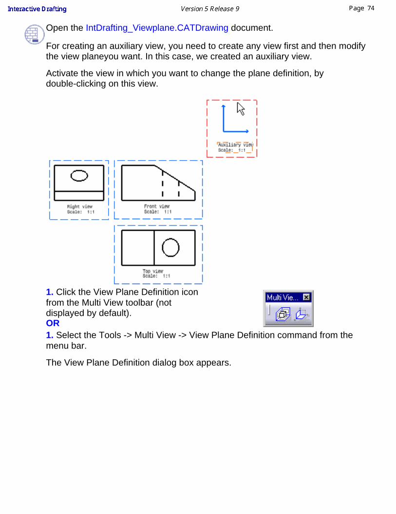
Open the IntDrafting_Viewplane.CATDrawing document.
For creating an auxiliary view, you need to create any view first and then modifythe view planeyou want. In this case, we created an auxiliary view.
Activate the view in which you want to change the plane definition, bydouble-clicking on this view.
1. Click the View Plane Definition iconfrom the Multi View toolbar (notdisplayed by default).OR1. Select the Tools -> Multi View -> View Plane Definition command from themenu bar.
The View Plane Definition dialog box appears.
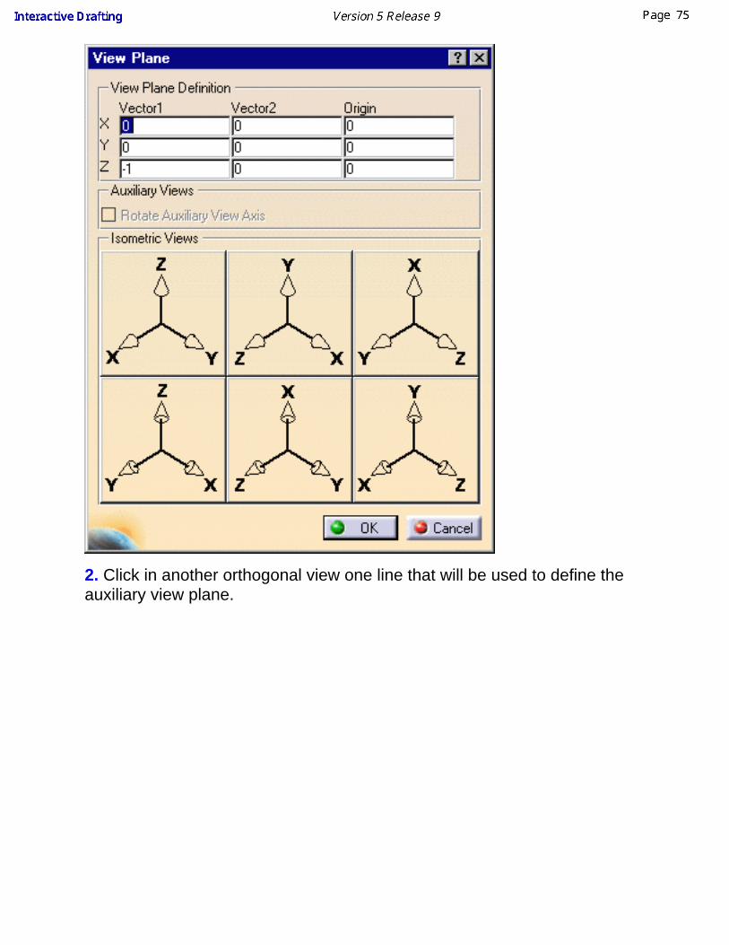
2. Click in another orthogonal view one line that will be used to define theauxiliary view plane.

The Plane Definition dialog box automatically displays the corresponding vectorsand origin point. The Rotate Auxiliary View Axis option is activate, by default.

3. Press OK.
The axis automatically rotates in accordance with the dialog box values appliedto the selected plane.
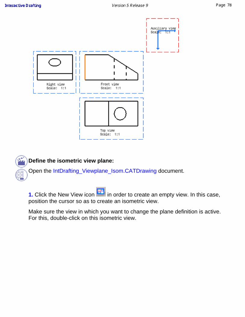
Define the isometric view plane:
Open the IntDrafting_Viewplane_Isom.CATDrawing document.
1. Click the New View icon in order to create an empty view. In this case,position the cursor so as to create an isometric view.
Make sure the view in which you want to change the plane definition is active.For this, double-click on this isometric view.

2. Click the View Plane Definition iconfrom the Multi View toolbar (notdisplayed by default).OR2. Select the Tools -> Multi View -> View Plane Definition command from themenu bar.
The Plane Definition dialog box appears.
3. Enter the desired options from the dialog box (Isometric).
OR
3. Select the desired pre-defined isometric view vectors. In this case, select YZX.

4. Press OK.

Creating Views Using Folding LinesThis task will show you how to add geometry in views using folding lines as an assistant.This is true for any kind of view, as long as the planes they correspond to are notparallel. For example, you cannot have folding lines between a front view and a rearview.Open the IntDrafting_Views_FoldingLines.CATDrawing document.
Go to Tools->Options->Mechanical Design->Drafting (General tab) and deactivate theGrid display option from the dialog box.
Make sure the view in which you are going to create geometry using folding lines isactive.
1. Right-click the view to used asreference.In this particular case, right-click thebottom view (which is not active andtherefore squared in blue).
2. Select the object ->Show folding Linesoption from the
displayed contextual menu.
In the case of more complex geometry,you can select one or more element(s) inthe reference view and display thecorresponding folding lines. As a result, theviews are not overloaded with folding lines.This is also true in the case of 2D components.
The folding lines appear.

At any time, you can right-click the viewand suppress these folding line using the
option
(contextual menu).
3. Click the Profile icon and create geometry in the top view using autodetection onfolding lines.
What you are now going to do is create geometry in the left view, of course using foldinglines.

4. Right-click the left view in which you aregoing to create geometry and select the
option from
the contextual menu.
The folding lines disappear.
5. Right-click both non active views one after the other and select the
option from the displayed contextual menu on each of theseviews.
The folding lines now appear as shownhere:

6. Click the Profile icon and creategeometry in the left view usingautodetection on folding lines.
7. Click a view and move it.Even when views are not aligned, folding lines remain associative.
All the above described functionalities are also true in the case of views with a differentscale.
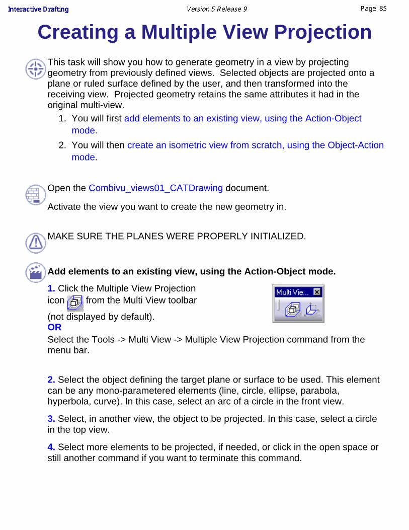
Creating a Multiple View ProjectionThis task will show you how to generate geometry in a view by projectinggeometry from previously defined views. Selected objects are projected onto aplane or ruled surface defined by the user, and then transformed into thereceiving view. Projected geometry retains the same attributes it had in theoriginal multi-view.
You will first add elements to an existing view, using the Action-Objectmode.
1.
You will then create an isometric view from scratch, using the Object-Actionmode.
2.
Open the Combivu_views01_CATDrawing document.
Activate the view you want to create the new geometry in.
MAKE SURE THE PLANES WERE PROPERLY INITIALIZED.
Add elements to an existing view, using the Action-Object mode.
1. Click the Multiple View Projectionicon from the Multi View toolbar
(not displayed by default).ORSelect the Tools -> Multi View -> Multiple View Projection command from themenu bar.
2. Select the object defining the target plane or surface to be used. This elementcan be any mono-parametered elements (line, circle, ellipse, parabola,hyperbola, curve). In this case, select an arc of a circle in the front view.
3. Select, in another view, the object to be projected. In this case, select a circlein the top view.
4. Select more elements to be projected, if needed, or click in the open space orstill another command if you want to terminate this command.

Create an isometric view from scratch, using the Object-Action mode.
1. Make the isometric view active (double-click).
2. Multi-select the elements to be projected into the isometric empty view. In thiscase, select the whole front view.
3. Click the Multiple View projection icon from the Multi View toolbar.
4. Select the object defining the view to be created.
All the elements are automatically projected onto the active view.
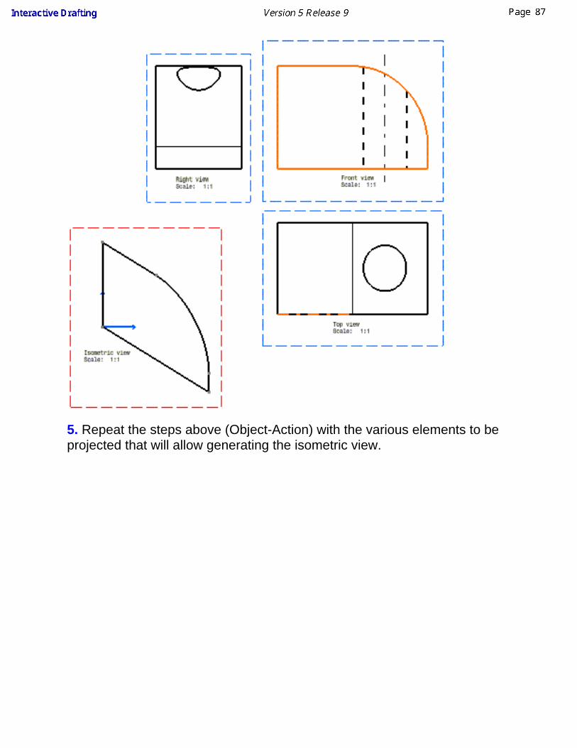
5. Repeat the steps above (Object-Action) with the various elements to beprojected that will allow generating the isometric view.
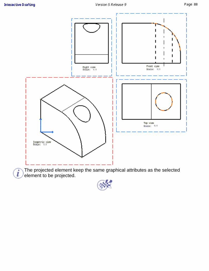
The projected element keep the same graphical attributes as the selectedelement to be projected.
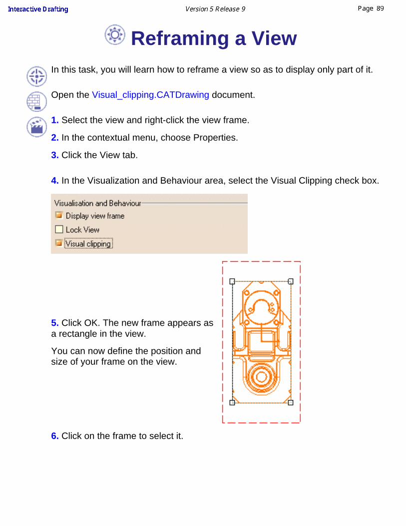
Reframing a View In this task, you will learn how to reframe a view so as to display only part of it.
Open the Visual_clipping.CATDrawing document.
1. Select the view and right-click the view frame.
2. In the contextual menu, choose Properties.
3. Click the View tab.
4. In the Visualization and Behaviour area, select the Visual Clipping check box.
5. Click OK. The new frame appears asa rectangle in the view.
You can now define the position andsize of your frame on the view.
6. Click on the frame to select it.
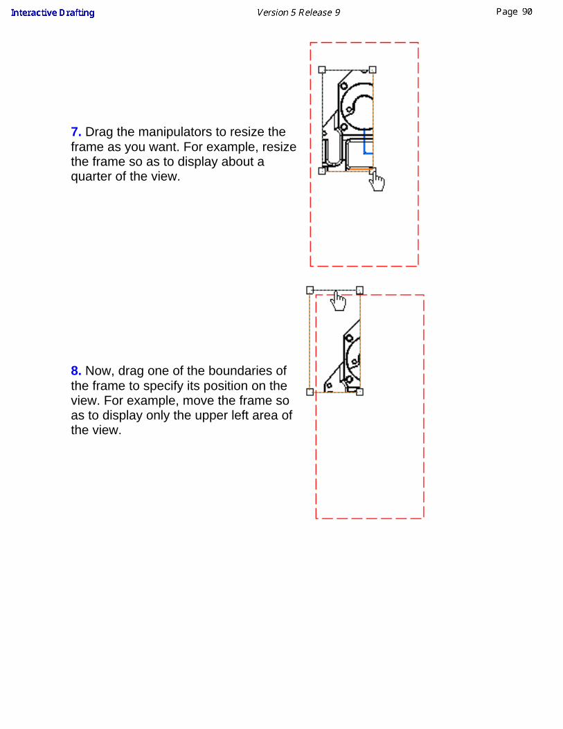
7. Drag the manipulators to resize theframe as you want. For example, resizethe frame so as to display about aquarter of the view.
8. Now, drag one of the boundaries ofthe frame to specify its position on theview. For example, move the frame soas to display only the upper left area ofthe view.

The frame is now displayed in the viewas you defined it.
The frame can only be rectangular.You can reframe any type of view: front views, isometric views, detailsviews, clipping views, etc.To remove the frame and display the view as it was originally before youreframed it, simply unselect the Visual Clipping check box.
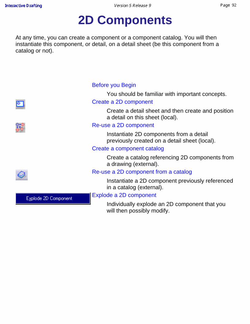
2D ComponentsAt any time, you can create a component or a component catalog. You will theninstantiate this component, or detail, on a detail sheet (be this component from acatalog or not).
Before you Begin
You should be familiar with important concepts.Create a 2D component
Create a detail sheet and then create and positiona detail on this sheet (local).
Re-use a 2D componentInstantiate 2D components from a detailpreviously created on a detail sheet (local).
Create a component catalogCreate a catalog referencing 2D components froma drawing (external).
Re-use a 2D component from a catalogInstantiate a 2D component previously referencedin a catalog (external).
Explode a 2D componentIndividually explode an 2D component that youwill then possibly modify.

Before You BeginWhat's a 2D Component?A 2D component is a re-usable set of geometry and annotations. This component is located in a sheetand can be edited like a view. This is why we call this component a detail view. The 2D componentcan be instantiated several times, each instance providing a component with a specific orientation,position and scale. The detail view can be either in the same drawing as the CATDrawing of thecorresponding instances or in a separate CATDrawing.
What's a Component Catalog?The catalog is a separate file which references the detail views, enabling to group the components, toclassify them and to add information and attributes to these components. This allows overallmanagement of the components. Moreover, the catalog browser can be used to choose a componentand instantiate it in a drawing document.
You can synchronize external catalog components. In other words, you may update a component (orditto) that is external to the 2D. Note that associativity is kept. For this, go to Edit->Link (menu bar) andselect the Synchronize switch from the displayed dialog box.
You can prevent manipulating a 2D component (the whole 2D component). For this, go to Tools ->Options -> Mechanical Design -> Drafting -> Geometry tab and de-activate the Allow DirectManipulation option.
General Concepts For Using Catalogs
Creating a 2D component in a detail sheet
You will find below a reminder on how to instantiate a component from a reference element that isinternal to the document.

1: reference component 2: instantiated component
Saving a 2D Component in a Catalog
You will find below how to instantiate a component from a reference element that is external to thedocument.

1: local copy of reference component2: instantiated components3: catalog entry4: external reference component
When you create a 2D component in a detail sheet, store this component into a catalog and youcan perform modifications to this component on the detail sheet. There are two ways forupdating the catalog file:- you can make a Save As Catalog on the same catalog. Be careful: in this case, the catalog isre-generated not updated. In other words, any modification applied to the catalog will be lost.- you can manually modify the catalog using the catalog editor (Base Infrastructure).
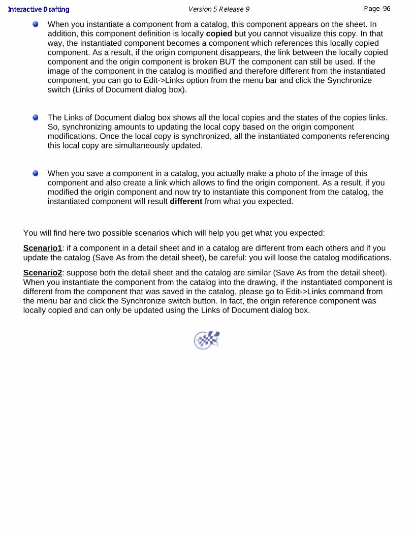
When you instantiate a component from a catalog, this component appears on the sheet. Inaddition, this component definition is locally copied but you cannot visualize this copy. In thatway, the instantiated component becomes a component which references this locally copiedcomponent. As a result, if the origin component disappears, the link between the locally copiedcomponent and the origin component is broken BUT the component can still be used. If theimage of the component in the catalog is modified and therefore different from the instantiatedcomponent, you can go to Edit->Links option from the menu bar and click the Synchronizeswitch (Links of Document dialog box).
The Links of Document dialog box shows all the local copies and the states of the copies links.So, synchronizing amounts to updating the local copy based on the origin componentmodifications. Once the local copy is synchronized, all the instantiated components referencingthis local copy are simultaneously updated.
When you save a component in a catalog, you actually make a photo of the image of thiscomponent and also create a link which allows to find the origin component. As a result, if youmodified the origin component and now try to instantiate this component from the catalog, theinstantiated component will result different from what you expected.
You will find here two possible scenarios which will help you get what you expected:
Scenario1: if a component in a detail sheet and in a catalog are different from each others and if youupdate the catalog (Save As from the detail sheet), be careful: you will loose the catalog modifications.
Scenario2: suppose both the detail sheet and the catalog are similar (Save As from the detail sheet).When you instantiate the component from the catalog into the drawing, if the instantiated component isdifferent from the component that was saved in the catalog, please go to Edit->Links command fromthe menu bar and click the Synchronize switch button. In fact, the origin reference component waslocally copied and can only be updated using the Links of Document dialog box.
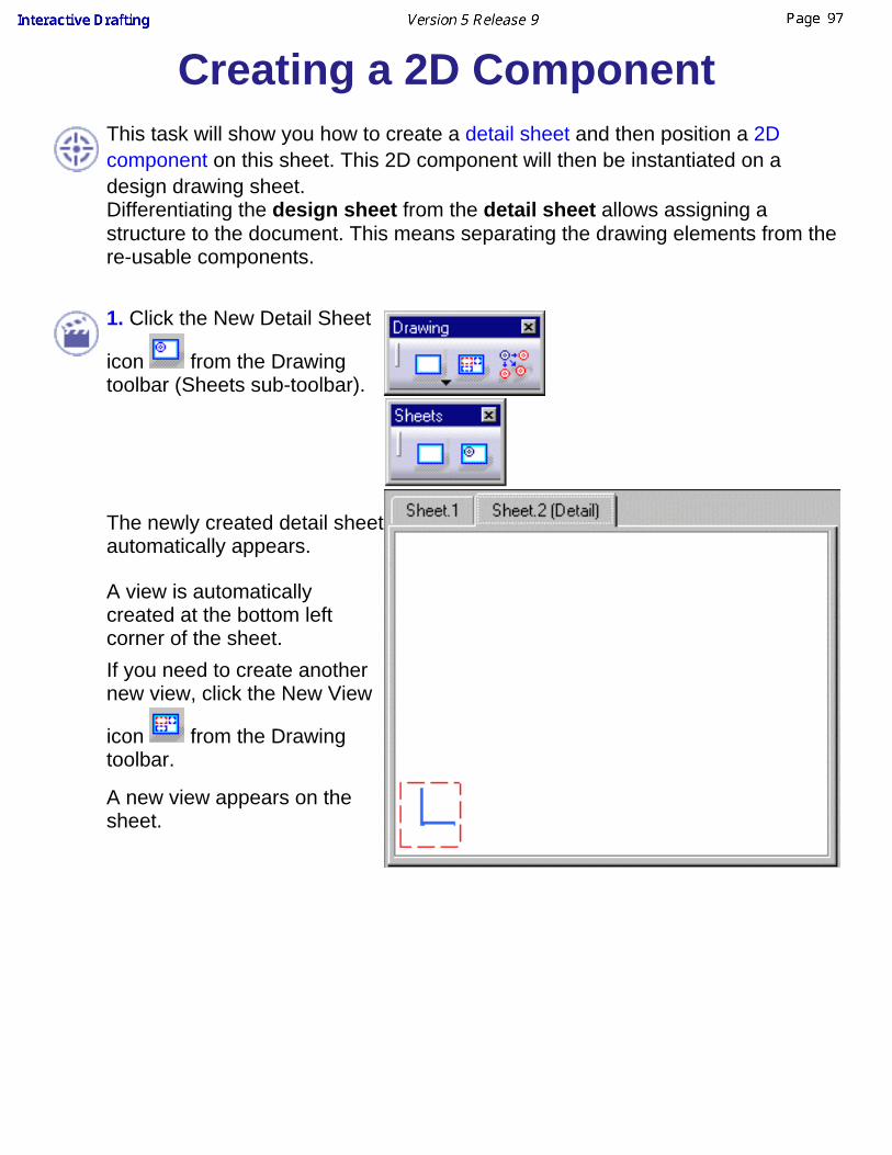
Creating a 2D ComponentThis task will show you how to create a detail sheet and then position a 2Dcomponent on this sheet. This 2D component will then be instantiated on adesign drawing sheet.Differentiating the design sheet from the detail sheet allows assigning astructure to the document. This means separating the drawing elements from there-usable components.
1. Click the New Detail Sheet
icon from the Drawingtoolbar (Sheets sub-toolbar).
The newly created detail sheetautomatically appears.
A view is automaticallycreated at the bottom leftcorner of the sheet.If you need to create anothernew view, click the New View
icon from the Drawingtoolbar.
A new view appears on thesheet.

3. Create a 2D componentinside this new view. Forexample, create two circles onthe detail sheet.
Note that you can customize both the design and the detail sheet backgroundcolors. For more information, see Infrastructure User's Guide.

Re-using a 2D ComponentThis task shows you how to re-use a 2D component. In this particular case, we willinstantiate a 2D component previously created on a detail sheet. Select a task:
Creating 2D Component instanceReplacing the Reference of a 2D Component InstancePositioning a 2D Component instance during creationAdd a leader to a 2D ComponentAutomating 2D Component instance creation with VB scriptModify text in 2D Component instancesAnnotation Orientation in 2D Component Instances
Open the Position_Component.CATDrawing document.
Creating a 2D Component instance
1. Double-click the view in whichyou want to instantiate the 2Dcomponent.This view is now active.
2. Click the Instantiate 2D
Component icon . Note thatto position several 2Dcomponents on the sheet andkeep the scale and angleproperties for all thesecomponents, you need todouble- click the Instantiate 2D
Component icon .
3. Go to the detail sheetSheet2(Detail) and click thecomponent.

You can select the 2D component from the design tree. You can also select acomponent that already exists on the drawing sheet.
The drawing sheet automaticallydisplays the sheet containing thestarting view.
4. Position the component usingthe picking assistant.
You can use the Tools toolbarfor positioning the componenteither before or after youinstantiate the 2D component.
5. If needed, select thecomponent and use thedisplayed manipulators to modifythe component.
You can also modify a group ofobjects including a 2Dcomponent. For this, multi-selectthe group of object and performthe desired modification(s).
To find easily and edit the reference 2D Component, double-click or right-click onthe 2D component you have instantiated, and choose Edit 2D reference option inthe contextual menu.
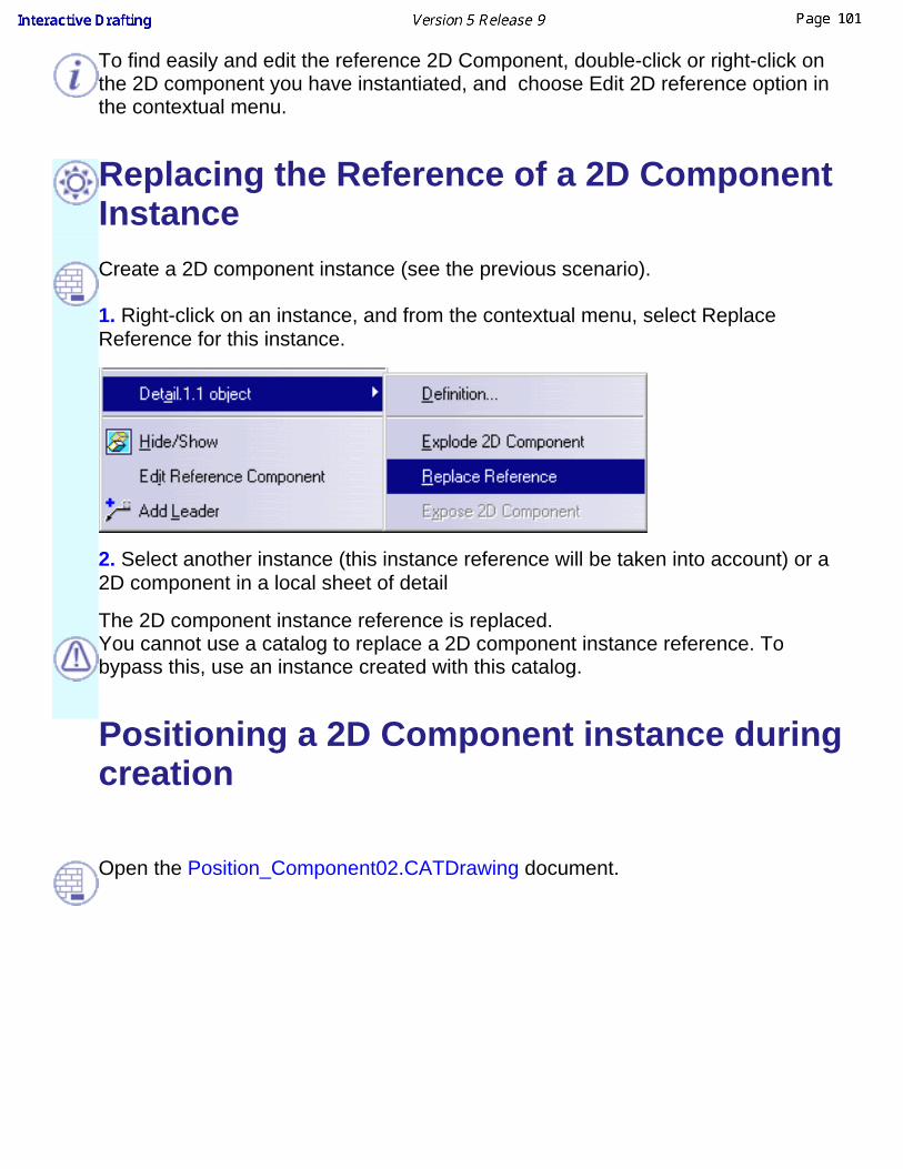
Replacing the Reference of a 2D ComponentInstance
Create a 2D component instance (see the previous scenario).
1. Right-click on an instance, and from the contextual menu, select ReplaceReference for this instance.
2. Select another instance (this instance reference will be taken into account) or a2D component in a local sheet of detail
The 2D component instance reference is replaced.You cannot use a catalog to replace a 2D component instance reference. Tobypass this, use an instance created with this catalog.
Positioning a 2D Component instance duringcreation
Open the Position_Component02.CATDrawing document.
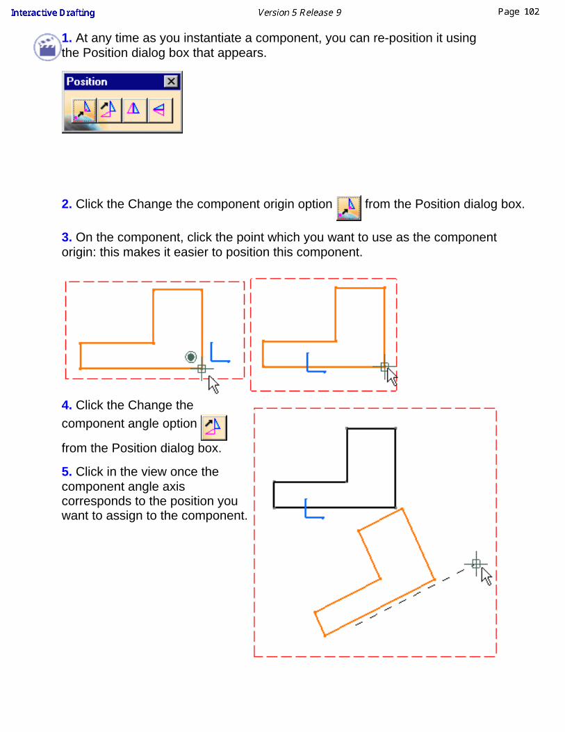
1. At any time as you instantiate a component, you can re-position it usingthe Position dialog box that appears.
2. Click the Change the component origin option from the Position dialog box.
3. On the component, click the point which you want to use as the componentorigin: this makes it easier to position this component.
4. Click the Change thecomponent angle option
from the Position dialog box.
5. Click in the view once thecomponent angle axiscorresponds to the position youwant to assign to the component.

You can also flip the component according to either the x axis or the y axis. If youclick the Flip component horizontally option , the component flips on the
horizontal axis of the detail. If you click the Flip component vertically option , the
component flips on the vertical axis of its reference .
Add a leader to a 2D component
Create a 2D component following the scenario Creating 2D component instance.
1. Right-click the 2D component and select Add Leader.
2. Select the element you want to associate to the 2D component, or click in emptyspace.
Automating 2D component instance creationwith VB script
Open the Position_Component.CATDrawing document.
1. Go to Tools -> Macro and select Start recording.
2. Key in the macro name and click on start button.

3. Create a 2D component instance using the Instantiate Detail icon .
4. Stop the recording clicking the following icon or go to Tools -> Macroand select Stop Recording.
Now you can create this 2D component instance automatically.
5. Delete the previous 2D Component instance. Go to Tools -> Macro -> Macros,select the macro and click the run button
This macro will be available only in this drawing.
6. A 2D component instance will be created at the same place as the previous one.
Modify text in 2D Component InstancesThis functionality allows you to modify 2D component texts.
Open the Position_Component.CATDrawing document.
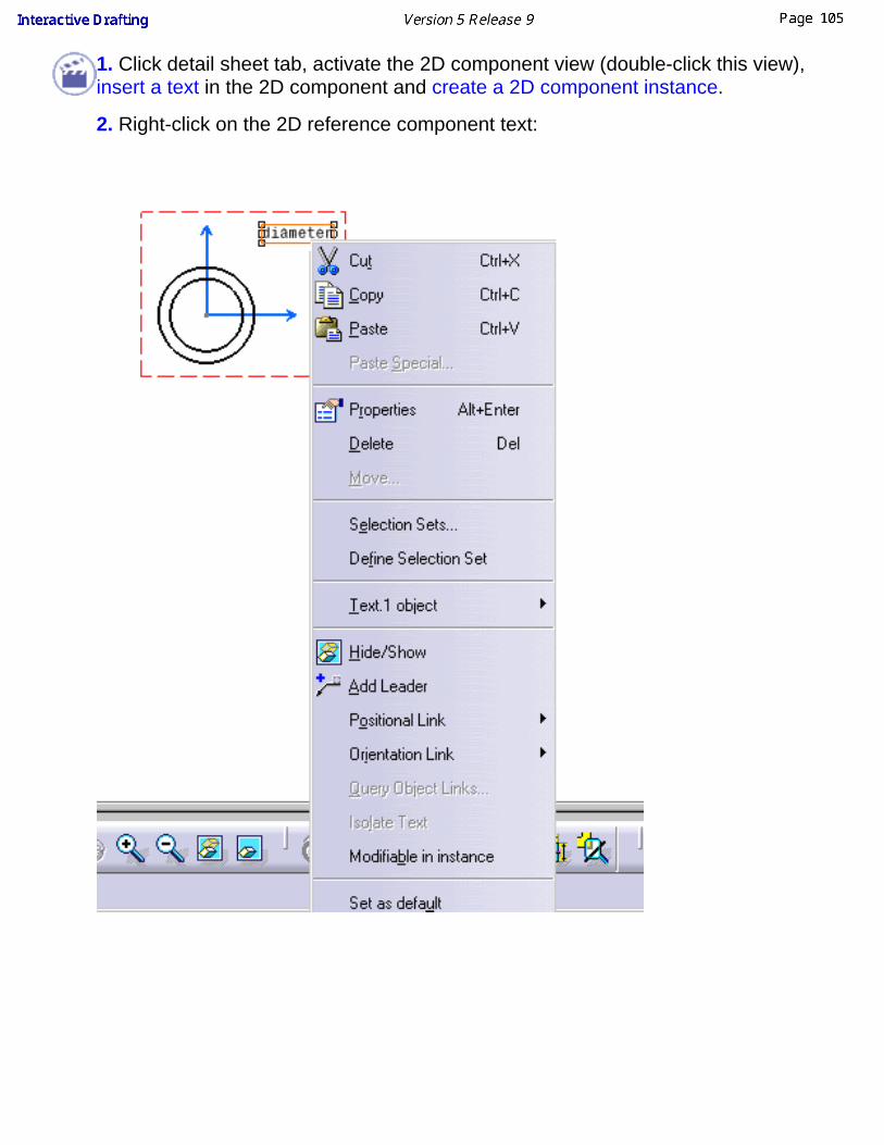
1. Click detail sheet tab, activate the 2D component view (double-click this view),insert a text in the 2D component and create a 2D component instance.
2. Right-click on the 2D reference component text:

3. Check Modifiable In instances.The text in the instances you have created and the ones you will create will bemodifiable.
4. Once more create a 2D component instance.
5. In the sheet one, double-click on the first 2D component instance text you havecreate, modify it and click to validate, then double-click on the second one. Modify itand click to validate.Both are modifiable.
Attribute links may be added in the text content,once a text becomes modifiable, it is not possible to make it non modifiable,when a 2D component text becomes modifiable, the new but also thecreated instances texts become modifiable,for 2D component instances created with catalog, if a text becomesmodifiable in catalog, you have to synchronise the external reference tomake the 2D component instance text modifiable too (see InfrastructureUser's Guide, advanced tasks -> Using Catalogs -> creating a catalog ).
Annotation Orientation in 2D ComponentInstancesThis functionality allows you to fix the text orientation in the 2D Component. In the2D Component Instances, the text will keep the same orientation even if the 2Dcomponent instance is rotated or flipped.
Open the Position_Component04.CATDrawing document.
1. Right-click on the text. Select Properties and Text tab. Choose to orientate the text horizontally relating to the sheet.

2. Create two 2D Component Instances, one without modifying the orientation andone orienting a 2D Component instance during creation. For the second instance,set the angle with the sheet to: 130°.
The 2D Component Text orientation in relation to the sheet is kept.
Not available for tables.
Text oriented view, summary table:
Originalorientation Horizontal Vertical Flip
HorizontalFlipVertical Rotate
Text rotatewith 2Dcomponentinstance
Textorientation isfixed andindependentfrom 2Dcomponentinstanceorientation

Creating a Component CatalogThis task will show you how to create 2D components in a drawing repository.In this particular case, we will create a component from re-usable geometry thatexist in a design sample CATDrawing document into a drawing repository. Notethat what you can do is create the desired geometry from scratch as you createthe catalog component. For this, you may, for example, copy the geometry, useSketcher commands or insert a DXF/DWG file.
You will thus be able to start creating a catalog (pointing the newly createdcomponent). In this catalog, component descriptions will be sorted identically tothe drawing and sheet structure.
We strongly advise that in a catalog you instantiate one part per sheet(multi-representation part) or one part family per sheet (mono-representationpart).
Add a Detail View in a Detail SheetAdd Existing Geometry to the Detail ViewCreate the Component Catalog
Open the DesignSample.CATDrawing document.
Add a Detail View in a Detail Sheet1. Open the BoldSample.CATDrawing document.
2. Click Bolds sheet (detail sheet in which the component is to be created).
3. Click the New View icon from the Drawing toolbar and position it on thesheet.
Add Existing Geometry to the Detail View
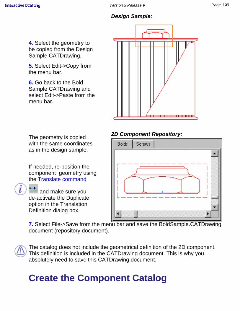
4. Select the geometry tobe copied from the DesignSample CATDrawing.
5. Select Edit->Copy fromthe menu bar.
6. Go back to the BoldSample CATDrawing andselect Edit->Paste from themenu bar.
Design Sample:
The geometry is copiedwith the same coordinatesas in the design sample.
2D Component Repository:
If needed, re-position thecomponent geometry usingthe Translate command
and make sure youde-activate the Duplicateoption in the TranslationDefinition dialog box.
7. Select File->Save from the menu bar and save the BoldSample.CATDrawingdocument (repository document).
The catalog does not include the geometrical definition of the 2D component.This definition is included in the CATDrawing document. This is why youabsolutely need to save this CATDrawing document.
Create the Component Catalog

8. Select File->Save Asfrom the menu bar andgenerate the componentcatalog pointing the newlypositioned component.
The Save as type "catalog" functionality is a simple way for creating a catalog.
If you want to edit the component, select File -> Open from the menu bar andopen the component.See Infrastructure User's guide for more details on this functionality.

Re-using a 2D Component from aCatalog
This task shows you how to re-use a 2D component you previously referenced in acatalog.Create a component catalog and enter a new CATDrawing in which you want toinsert one or more 2D components.
1. Click the Catalog Browser icon from the Catalog toolbar.
The Catalog Browser dialog box appears with the following information:the name ofthe currentlyopenedcatalog.the catalogchapter tree.a preview ofthe selectedcomponent.the possibilityto perform aquery onavailablecomponents(seeKnowledgeAdvisor user'sguide for moredetails onformulas).
2. Click the Browseanother catalog
option from theCatalog Browserdialog box and opentheBoldSample.catalogdocument from the\online\driug\samples

directory.
3. Double-click the Bolds chapter from the chapter tree.
The list with the components included in the Bolds chapter appears in the dialogbox. 4. Click Detail.7 fromthe list available.You now have apreview of thecomponent you justselected.
5. Drag the detailfrom the list andposition this detailonto the desiredCATDrawing.(at this step, thedialog is the same aswhen you re-use a2D component).
6 Click to end detaillocation.
What you can alsodo is display thecontextual menu onthe selectedcomponent andselect the Instantiateoption. You will thenposition thecomponent on theCATDrawing.If you double-clickthe component fromthe Catalog Browser,the following dialogbox appears whichallows modifying the2D component originor angle.

The CATDrawing in which you locally instantiated a catalog component isautonomous. In other words, you do not necessarily need the catalog to beable to read the CATDrawing.There is a link that exists between the CATDrawing and the catalog.

Exploding a 2D ComponentThis task shows you how to individually explode an 2D component that wasinstantiated from a detail sheet. You will then modify as desired this component.
Open the Explode_Component.CATDrawing document.
1. Right-click the component that was previously instantiated from the detailsheet and select the Explode 2D Component option from the contextual menu.
The component is now exploded. You can therefore modify the geometry and/orgraphical properties on one or more elements of this component.
2. Click the text and re-position it.
3. Select one line on the top of the hexagon and use the Graphical Propertiestoolbar to change the color into red.
The component now appears as desired:


DimensionsThe Interactive Drafting workbench provides a simple method to create andmodify given types of dimensions using the Dimensions toolbar:
Before You Begin:
You should be familiar with basic concepts.Create dimensions:
Create dimensions by clicking elements.Create half-dimensions:
Create half dimensions on distance, angle, diameter, cylinders, diameteredges and diameter tangents but not on cumulate dimensions.
Create/Modify angle dimensions:Create an angle dimension and perform the following kinds ofmodifications: new angle sector or turn an angle sector into asupplementary sector.
Modify the dimension type:Modify the dimension type as you create a dimension. On other words,you modify the dimension attributes.
Create driving dimensionsCreate dimensions that will drive associated constrained geometry.
Interrupt one or more extension lines:Interrupt manually one or more extension lines of one or moredimensions, either using the contextual menu or the Insert menu baroption.
Modify the dimension line location:Use the mouse to modify dimension line location either before or aftercreating dimensions.
Modify the dimension value text position:Use the cursor to modify dimension value text position.
Modify the text before/after:Insert text before or after the dimension value.

Modify the dimension overrun/blanking:Use the Blanking Edition dialog box to modify dimension overrun orblanking.
Set relations between driving dimensionsSet relations between driving dimensions.
Create/modify coordinate dimensions:Automatically create coordinate dimensions on elements.
Create cumulated dimensions:Create cumulated dimensions on a view using selection.
Create stacked dimensions:Create stacked dimensions using selection.
Create explicit dimensions:Create dimensions using explicit selection both of the desired icon andof the required geometrical elements.
Generate a holes dimensions table:Generate a Holes Dimensions Table (containing diameter and centercoordinates).
Create Points Coordinates table:Create a Table containing 2D and 3D points coordinates.
Creating Associative Thread Dimensions:Create associative thread dimensions.
Create chamfer dimensions:Create a chamfer dimension using selection.
Line up dimensions (free space):Line up dimensions relatively to a point in the free space.
Line up dimensions (reference):Line up dimensions according to a given reference.
Create a datum feature:Use the Datum Feature Creation dialog box to create a datum feature.
Modifying a Datum Featuremodify a datum feature by editing it.

Create a geometrical tolerance:Use the the Geometric Dimensioning And Tolerancing Parametersdialog box to create geometrical tolerances.
Modify a geometrical tolerance:Use the the Geometric Dimensioning And Tolerancing Parametersdialog box to modify geometrical tolerances.
Edit/Search dimensions status:Use the advanced search command in drafting workbench.

Before You BeginYou should be familiar with the following concepts:
Creating DimensionsYou can create (and therefore modify) the following types of dimensions:Dimensions created on one element:
Length dimensionsDiameter dimensionsRadius dimensions
Dimensions created on two elements:Distance dimensionsAngle dimensionsDiameter/Radius Cylinder dimensions
Note that you can create half-dimensions on distance, angle, diameter cylinder, diameteredge and diameter tangent dimensions but not on cumulate dimensions.
Modifying the Dimension AttributesYou can modify the following attributes at any time before you click to validate thedimension creation:Modify while creating:
TypeMeasure directionAngle sector
Modify while or just after creating:Value positionExtension line overrun/blanking (either one or both)Text before/afterProperties (see further down)

Manipulating DimensionsBy default, when manipulating dimensions, you will use the following functionalities:
dimension following the mouseGo to Tools -> Options -> Drafting (Dimension tab) to use automatic positioningglobal moveGo to Tools -> Options -> Drafting (Dimension tab) to move precisely dimensionline, dimension value, secondary part of a dimension line).blanking manipulators available when modifying a dimensionGo to Tools -> Options -> Drafting (Manipulators tab) not to visualize blankingmanipulators or to visualize other manipulators either when creating or whenmodifying a dimension (Overrun, Blanking, Insert text before, Insert text after, Movevalue, Move dimension line, Move DimLine Secondary Part).value snapped between the dimension lines symbolsGo to Tools -> Options -> Drafting (Dimension tab) if you do not want to have thepossibility to snap the dimension value between both symbols of the dimension lineand/or you want to snap the dimension position on the grid.during creationTo switch temporarily the Dimension following the mouse option, hold on the ctrlkeyduring creation and editionTo switch temporarily the Activate Snapping option, hold on the shift key. Clickingon the dimension symbols will invert them.during angle dimension creationIf the Dimension following the mouse option is activated, you can swap the anglesector according to the mouse position holding on the ctrl and shift keys. If the Dimension following the mouse option is not activated, you can swap to thecomplementary angle sector holding on the ctrl key and clicking on the dimensionline.
Dimension PropertiesYou can apply given properties to all the dimensions you are going to create. For this, usethe Dimension Properties toolbar.
Line type (one part dimension, two part dimension or two part leader)Tolerance type Tolerance value Numerical Display FormatPrecision.
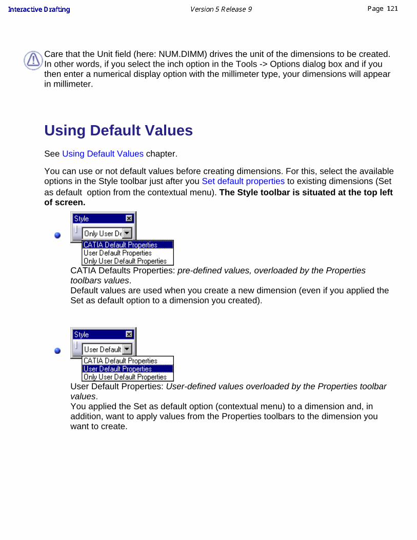
Care that the Unit field (here: NUM.DIMM) drives the unit of the dimensions to be created.In other words, if you select the inch option in the Tools -> Options dialog box and if youthen enter a numerical display option with the millimeter type, your dimensions will appearin millimeter.
Using Default Values See Using Default Values chapter.
You can use or not default values before creating dimensions. For this, select the availableoptions in the Style toolbar just after you Set default properties to existing dimensions (Setas default option from the contextual menu). The Style toolbar is situated at the top leftof screen.
CATIA Defaults Properties: pre-defined values, overloaded by the Propertiestoolbars values.Default values are used when you create a new dimension (even if you applied theSet as default option to a dimension you created).
User Default Properties: User-defined values overloaded by the Properties toolbarvalues.You applied the Set as default option (contextual menu) to a dimension and, inaddition, want to apply values from the Properties toolbars to the dimension youwant to create.

Only User Default Properties: User-defined values not overloaded by the Propertiestoolbars values.You applied the Set as default option (contextual menu) to a dimension and will notuse the Properties toolbar in order to apply more values to the dimension you wantto create. These Properties toolbars automatically become non modifiable (fieldsset to the gray color).
Reset Default Values
Create a text using default values (contextual menu: Set as Default option).
1. Select Tools -> Reset All Default from the menu bar.
All the default values are reset.

Creating Dimensions In this task, you will learn how to create dimensions. When creating dimensions on elements, you canpreview the dimensions to be created.
You will learn how to perform the following operations:Creating DimensionsSpecifying the Dimension Display ModeDimension Leader managementCreating dimensions between an element and view axis (the two axes or the origin)PropertiesAssociativityDriving DimensionsTrue DimensionsExtension Line AnchorHalf-DimensionsSlanted Extension Lines
Creating Dimensions Open the Brackets_views02.CATDrawing document.
1. On the Dimensioning toolbar, click the
Dimensions icon.
2. Click a first element in the view. For example, acircle.
3. If needed, click a second element in the view.The dimension type is automatically defined
according to the selected elements ( or inthe Tools toolbar).
At this step, the command options in the Tools toolbar ( ) allows you to positionthe dimension using one of the modes below: Projected, Forced or True Length modes. These optionsare also available in the contextual menu.
This toolbar is situated at the bottom right of screen. If you cannot see it properly, just undockit.

4. Click the Force Dimension on element command option from the Tools toolbar.
5. Right-click to access the contextual menu and select 1 symbol.
The dimension becomes a one-symbol dimension:
During the dimension creation step, you can switch between one-symbol or two-symbols dimension.Once the dimension has been created, you must use the Properties menu to specify whether you wantto use one or two symbols. Right-click the dimension and in the contextual menu, choose Properties.Click the Dimension Line tab and then check Display Symbol 2 to display two-symbols dimension, oruncheck this option to display one-symbol dimension.

6. Click in the drawing window to validate the dimension creation. 7. Create an other dimension on a line.
8. Select the two dimensions with the Ctrl key (you can move them both).
9. Start creating another dimension: click the command icon and select another circle:
Click in the drawing to validate the creation.
10. Right-click the dimension you just created and in the contextual menu, choose Dimension.3 Objectand select Swap to Radius:

The diameter dimension has swapped to radius dimension:
11. Right-click the dimension again, and in the contextual menu, choose Dimension.3 Object, anduncheck Extend to Center: the radius extension line is not extended until the center anymore.

You can use this functionality through the Properties menu: right-click on the dimension andchoose Properties. On the Dimension Line tab, select the type of extension you want from theExtension list: From standard, Till center or Not till center.
This functionality works with radius dimension and one-symbol diameter dimension.
Specifying the Dimension Display Mode In this task, you will learn how to specify the display mode for a dimension.
Create a dimension as explained above.
1. Select the dimension and right-click it.
2. Click Properties in the menu that appears. The Properties dialog box appears.3. Click the Text tab.

4. In the Options area, choose the display mode youwant for your dimension from the Display list.
You have the following options:
Show Value: displays the dimension and its leader. This option is selected by default.
Show Box: replaces the dimension by a rectangular box and displays its leader.
Hide Value: hides the dimension but displays its leader.
5. Click OK to validate. The dimension is now displayed using the mode you set.
Dimension Leader management Create a dimension as explained above.
1. Right-click on this dimension and in the contextual menu choose Properties, then select theDimension Line tab.
2. From the Representation drop-down list, choose Leader two Parts.

3. In the Leader Angle field, specify the angle you want between the two parts of the leader.
This angle is applied to the first segment:
You can also drive the second segment from the options in the Second Part area: it can be horizontal,vertical, parallel, perpendicular, fixed angle with screen, view, or dimension horizontal and vertical.
4. Change the Leader symbol in Symbols-> Shape:
5. Transform this two parts leader into a one part leader: from the Representation drop-down list,choose Leader one Part.
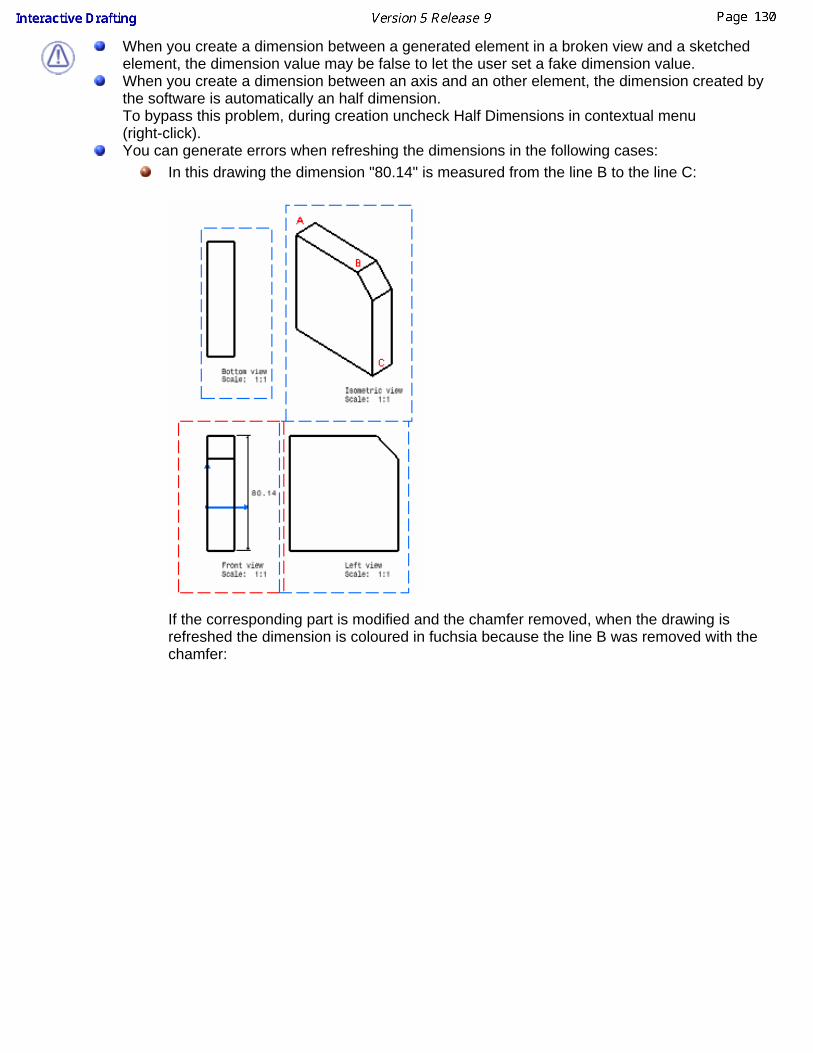
When you create a dimension between a generated element in a broken view and a sketchedelement, the dimension value may be false to let the user set a fake dimension value.When you create a dimension between an axis and an other element, the dimension created bythe software is automatically an half dimension. To bypass this problem, during creation uncheck Half Dimensions in contextual menu(right-click). You can generate errors when refreshing the dimensions in the following cases:
In this drawing the dimension "80.14" is measured from the line B to the line C:
If the corresponding part is modified and the chamfer removed, when the drawing isrefreshed the dimension is coloured in fuchsia because the line B was removed with thechamfer:

If the two elements separated by the dimension value are move and then merged the itwill generate an error and the dimension will be fuchsia:
Creating dimensions between an element and a viewaxis (the two axes or the origin)
Open the IntDrafting_Viewplane_Front.CATDrawing document.
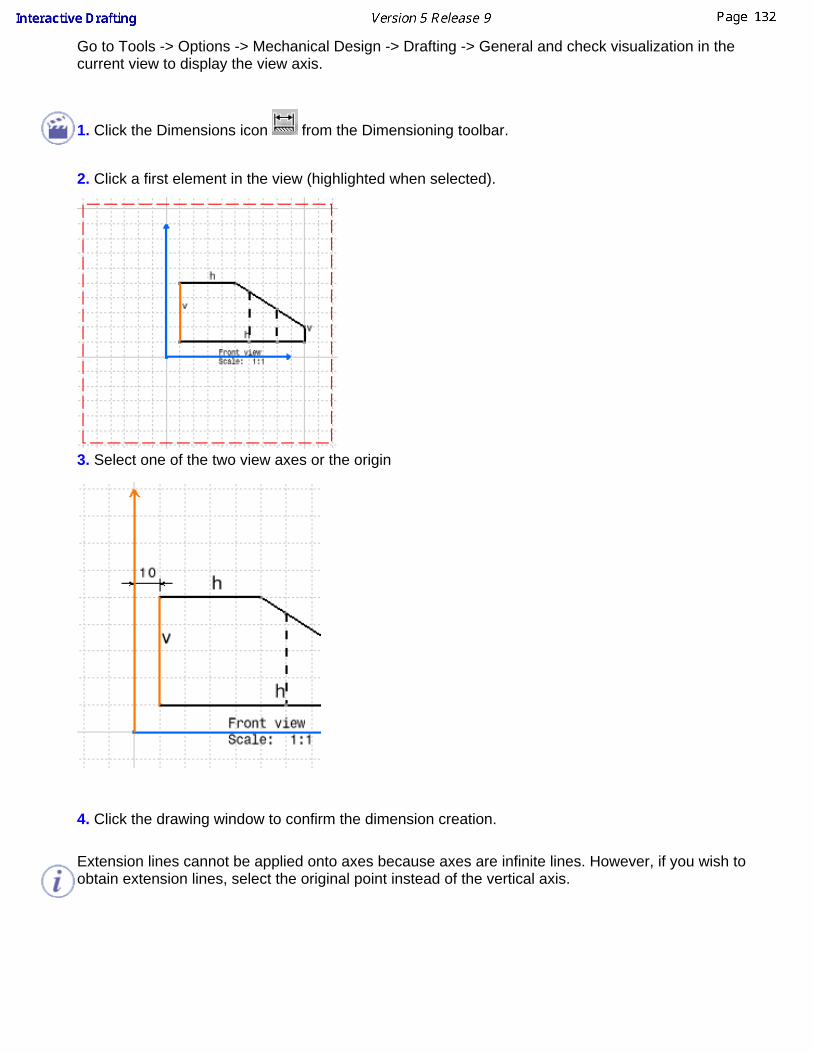
Go to Tools -> Options -> Mechanical Design -> Drafting -> General and check visualization in thecurrent view to display the view axis.
1. Click the Dimensions icon from the Dimensioning toolbar.
2. Click a first element in the view (highlighted when selected).
3. Select one of the two view axes or the origin
4. Click the drawing window to confirm the dimension creation.
Extension lines cannot be applied onto axes because axes are infinite lines. However, if you wish toobtain extension lines, select the original point instead of the vertical axis.

PropertiesIf you right-click the dimension before creation, a contextual menu lets you modify the dimension typeand value orientation as well as add funnels. Using this contextual menu once the dimension is created,you can also access the Properties options.
AssociativityIf one parent element of the dimension is deleted or deactivated, as soon as you update the drawing(either 3D Generative or 2D Interactive drawing), the orphan dimension becomes purple on the
condition you activated the Analysis Display Mode option from the Tools toolbar.
Ensure that if you key in "c: Force Update" to synchronize the drawing with the 3D, anynon-associative dimension will disappear.
Colors can be customized using the Analysis Display Mode option from the Tools toolbar or viaTools->Options->Drafting, Dimension tab).
Driving DimensionsYou can create dimensions that will, by default, drive the geometry. For this:
Go to Tools -> Options (Dimension tab) and activate the Create driving dimension option fromthe Options dialog box.
Create and/or modify the desired dimension on the geometry. If needed, you can use the Toolstoolbar and define the Value of the dimension you want to be driving.
For more information, refer to Creating Dimension Constraints.
True Dimensions
True Length dimensions can be created using the True Length Dimensions option from the Toolstoolbar or using the contextual menu.

Before using true dimensions make sure that in tools->Options->Associativity on 3D, you have not setonly create non-associative dimensions option, to work this functionality must be applied to anassociative dimension.
Extension Line AnchorAs you create a dimension between two elements, one of these elements being a circle, you can selectthe extension line anchor, for this, you can :
use the contextual menu (positioned on the dimension) and select one of the available ExtensionLine anchor options.
You will thus position the extension line:at one extremity of the circle (First Anchor)at the center of the circle (Second Anchor)at one extremity of the circle (Third Anchor)
drag the yellow symbol to the one of the anchors (anchors appear when the cursor is over theyellow symbol):
If in Tools -> Options -> Mechanical Design -> Drafting -> Dimension, you have checked Dimensionfollowing the mouse option, then to move the extension line anchor you must hold on the crtl key beforeselecting the yellow symbol (to switch temporarily the option).
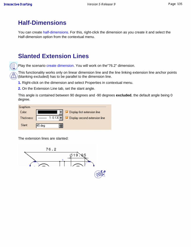
Half-DimensionsYou can create half-dimensions. For this, right-click the dimension as you create it and select theHalf-dimension option from the contextual menu.
Slanted Extension LinesPlay the scenario create dimension. You will work on the"76.2" dimension.
This functionality works only on linear dimension line and the line linking extension line anchor points(blanking excluded) has to be parallel to the dimension line.
1. Right-click on the dimension and select Properties in contextual menu.
2. On the Extension Line tab, set the slant angle.
This angle is contained between 90 degrees and -90 degrees excluded, the default angle being 0degree.
The extension lines are slanted:

Creating Half-DimensionsHalf-Dimensions are useful in the case of revolved features or elements using aplane symmetry. Actually it allows to create the dimensions only on half thegeometry.
This task will show you how to create a half-dimension. You can createhalf-dimensions on distance, angle, diameter, cylinders, diameter edges anddiameter tangents but not on cumulate dimensions.
Open the Brackets_views05.CATDrawing document.
1. Click the Dimensions icon from the
Dimensioning toolbar.
2.
Click a first element in the view. Forexample, an edge.
3.
If needed, click a second element in theview. For example, another edge.
4.
Right-click the dimension and select theHalf-dimension option from thecontextual menu.

The half-dimension appears. Only oneextension line is displayed. Thedimension line is shortened with specificoverrun, gap and length. The value isnot centered on the dimension line. Theattributes mentioned in ManagingStandards drive the dimension graphicdisplay.
Once you select the Half-dimension option from the contextual menu, all thefollowing dimensions you create will be assigned the half-dimension mode.If you want to create dimensions in the standard mode, go back to thecontextual menu and de-activate the Half-dimension option.If you create half-dimensions by selecting two elements, select first thesymmetry axis, then the element. The half-dimension value will be thedouble of the measured value between the elements.When you create a dimension between an axis and an other element, thedimension created by the software is automatically an half dimension. To bypass this problem, during creation uncheck Half Dimensions incontextual menu (right-click).
Associativity in the case of half-dimensions is different from associativity in thecase of standard dimensions. For example, the half diameter dimension below isassociated to the axis and the element, whereas a standard diameter isassociated to both symmetrical elements.
Standard diameter edge: Half diameter edge:


Creating/Modifying AngleDimensions
This task will show you how to create an angle dimension and perform thefollowing kinds of modifications: new angle sector or turn an angle sector into asupplementary sector.Create two lines.
1. Select the Dimension
icon from theDimensioning toolbar.
2. Select both lines to be dimensioned, one after theother.
The angle dimensionappears in the sectorassociated to bothselected lines.
3. Drag the angledimension line to thedesired quadrant (orsector).
You can move the dimension to a new sector by using the contextual menu:

Right-click the angledimension and select fromthe contextual menu eithera given Angle sector orthe Complementary Anglesector.
You can also control-clickthe dimension line.
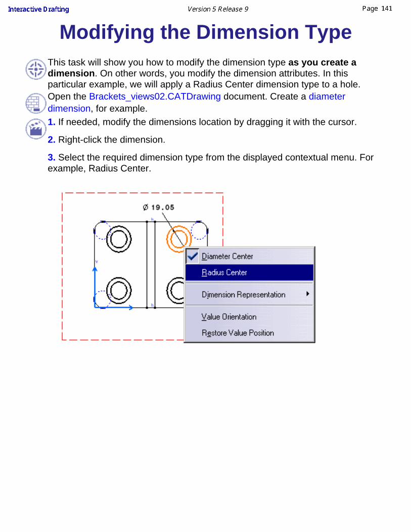
Modifying the Dimension TypeThis task will show you how to modify the dimension type as you create adimension. On other words, you modify the dimension attributes. In thisparticular example, we will apply a Radius Center dimension type to a hole.Open the Brackets_views02.CATDrawing document. Create a diameterdimension, for example.1. If needed, modify the dimensions location by dragging it with the cursor.
2. Right-click the dimension.
3. Select the required dimension type from the displayed contextual menu. Forexample, Radius Center.

The diameter dimension is automatically snapped to a radius dimension.
4. Click the drawing window to validate the dimension creation and, if needed,modify the dimension location.
When you display the contextual menu, you can decide that you want torestore the dimension value to its original position. For this, select theRestore Value Position option from the contextual menu.When you display the contextual menu, you can define the valueorientation with the screen, view or dimension line as reference, or stillhorizontal, vertical or according to a fixed angle. These options areavailable in the Value Orientation dialog box.

Interrupting Extension Lines
This task will show you how to interrupt manually one or more extension lines ofone or more dimensions, either using the contextual menu or the Insert menu baroption.
Open the Interruption_ExtLine01.CATDrawing document.
Use the contextual menu or the toolbar:
1. Right-click a dimension and select the Object -> Create Interruption option fromthe contextual menu.
or select a dimension and click on the Create Interruption icon .
2. Choose in the Tools toolbar how many interruptions you want to create
3. Indicate the first point defining the interruption to be created.
4. Indicate the second point defining the interruption to be created.
If you have chosen one interruption in the Tools toolbar, the interruption isautomatically created on the closest extension line.

Open the Interruption_ExtLine02.CATDrawing document.
Use the Insert menu bar option:
1. Select one or more dimensions.
2. Select the Insert -> Dimensioning -> Dimensions -> Extension LineInterruptions -> Create Interruption option from the menu bar.
3. Choose in the Tools toolbar how many interruptions you want to create
4. Indicate the first point defining the interruption to be created.
5. Indicate the second point defining the interruption to be created.
The interruption (s) is/are automatically created on every extension line of theselected dimension(s).

You can remove the interruption youcreated by selecting one dimension, theRemove Interruption option and then theextension line not to be interrupted anymore. Interruption is removed on theextension line nearest the selectionpoint.
You can also remove all the interruptions applied to one or more dimensions. Forthis, (multi-)select the dimension(s) and then the Remove All Interruptions option.Interruptions are removed on all the extension lines lines of the selecteddimension(s).

If you move the dimension, the interruption will remain as you created it.If you modify either the overrun and / or the blanking, the interruption alsoremains the same.
You can apply height interruptions maximum to an extension line.
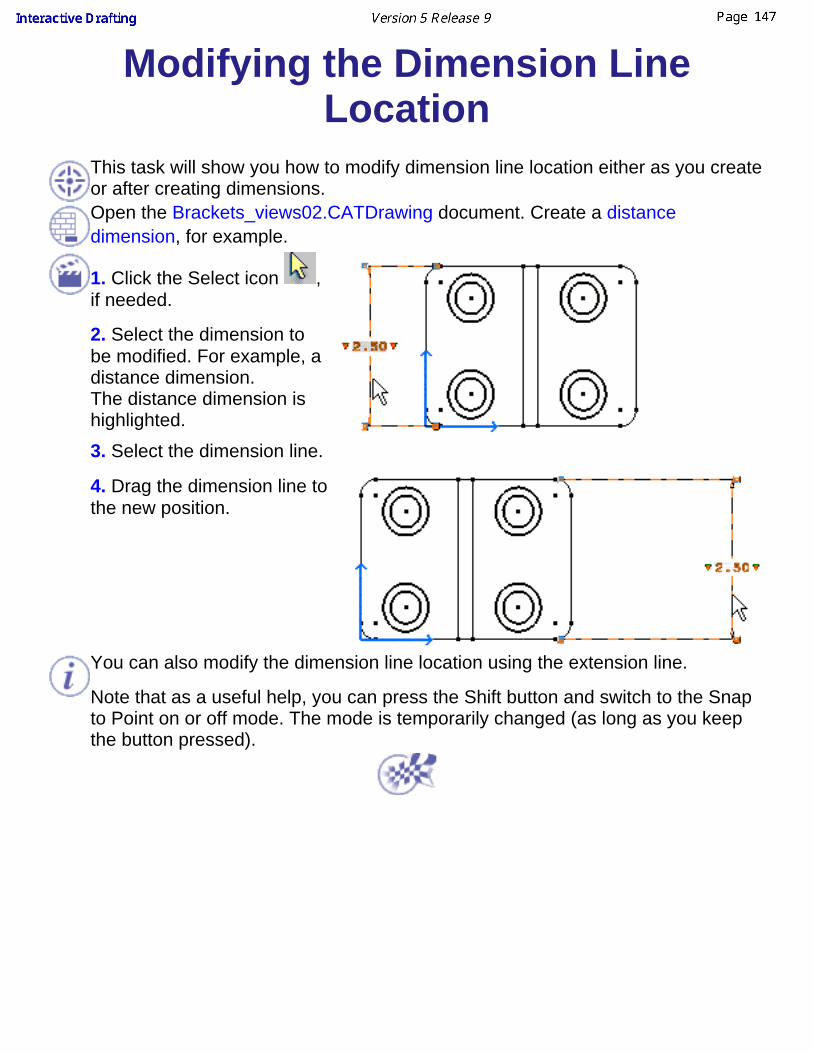
Modifying the Dimension LineLocation
This task will show you how to modify dimension line location either as you createor after creating dimensions.Open the Brackets_views02.CATDrawing document. Create a distancedimension, for example.
1. Click the Select icon ,if needed.
2. Select the dimension tobe modified. For example, adistance dimension.The distance dimension ishighlighted. 3. Select the dimension line.
4. Drag the dimension line tothe new position.
You can also modify the dimension line location using the extension line.
Note that as a useful help, you can press the Shift button and switch to the Snapto Point on or off mode. The mode is temporarily changed (as long as you keepthe button pressed).

Modifying the Dimension Value TextPosition
This task will show you how to modify the position of the dimension value textusing the mouse.Open the Brackets_views02.CATDrawing document. Create a distancedimension, for example.
1. Click the Select icon , if needed.
2. Select the dimension value text.
3. Drag the value text to the new position.
4. Click to validate the position.
Note that as a useful help, you can press theShift button and switch to the Snap to Point onor off mode. The mode is temporarily changed(as long as you keep the button pressed).
When the Snap to Point mode is on, as youselect and drag the dimension value, ananchor appears to help you locate themiddle of the dimension.
At any time, you can restore the original value text position. To do this, right-clickthe dimension you positioned and select Restore Value Position from the
contextual menu.

Adding Text Before/After theDimension Value
This task will show you how to insert text before or after the dimension value.
Open the Brackets_views02.CATDrawing document. Create a distancedimension, for example.
1. Click the Select icon , if needed.
2. Click the dimension to be modified.The dimension is highlighted and two redtriangles appear both left and right of thedimension value.
3. Click the left red triangle, for example.
The Insert Text Before dialog boxappears:
4. Enter, for instance, L = .
5. Click OK. The text is automaticallyinserted before the dimension value. Any created Text Before is automatically added to the drop-down list box andcan therefore be selected again from this list.
6. Click in the free space.

Modifying Dimension Overrun/BlankingThis task shows you how to modify dimensions extension line overrun and/or blanking either together orseparately.
Open the Brackets_views02.CATDrawing document. Create a distance dimension, for example.
1. Drag the overrun manipulator(s) to a new position, as shown herebelow:
Press the Ctrl key and drag the desired manipulator for modifying one extension line only.
2. Drag the blanking manipulator(s) to a new position, as shown herebelow:
3. If you need to be more precise, double-click themanipulator.
The Blanking Edition dialog box displays.
4. Enter the desired value to modify the blanking.
You can also modify the overrun/blanking of only oneextension line of the dimension.
5. Double-click the overrun manipulator(s).

The Overrun Edition dialog box appears.
6. Enter the desired overrun value and un-check theApply to both sides option from the Overrun Editiondialog box.
Note that you can also right-click the dimension and select the Edit -> Properties option from the displayedcontextual menu. The Properties dialog box appears. Select the Extension Line tab and modify the desiredvalue(s) of the Overrun / Blanking Extremities option(s).
Overrun is the overrun minimum value. As an example, for a cumulated dimension (for ISO Standard):
you can increase the overrun size you can not decrease it below the minimum value
To set Cumulate dimension extension line length and text position, see following parameter: CUMLExtMode inManaging Standards.

Creating/Modifying CoordinateDimensions
This task will show you how to automatically create coordinate dimensions onelements. Coordinate dimensions allow you to define the coordinates of a pointrelative to X and Y axes.
Open the PointSketch.CATDrawing document.
1. Click the Coordinate Dimension icon from the Dimensioning toolbar(Dimensions subtoolbar).
2. You can choose between creating generated geometry (3D) coordinatesdimensions or sketched (2D) geometry coordinates dimensions.
Two icons appear in the Tools toolbar after clicking the command icon ,
one for the creation of 2D (x, y) coordinates dimensions and one for 3D (x,
y, z) coordinates dimensions .
These icons appear only if you have selected elements from 3D.
Select the 3D (x, y) icon in the tools box.
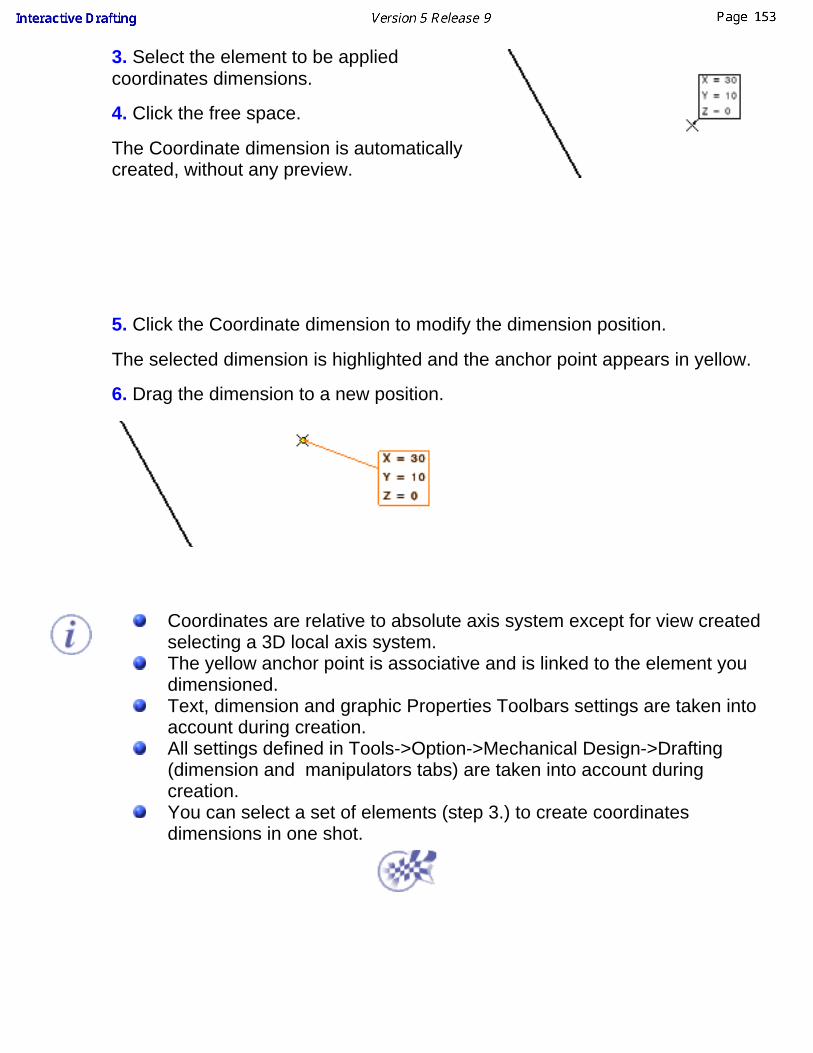
3. Select the element to be appliedcoordinates dimensions.
4. Click the free space.
The Coordinate dimension is automaticallycreated, without any preview.
5. Click the Coordinate dimension to modify the dimension position.
The selected dimension is highlighted and the anchor point appears in yellow.
6. Drag the dimension to a new position.
Coordinates are relative to absolute axis system except for view createdselecting a 3D local axis system.The yellow anchor point is associative and is linked to the element youdimensioned.Text, dimension and graphic Properties Toolbars settings are taken intoaccount during creation.All settings defined in Tools->Option->Mechanical Design->Drafting(dimension and manipulators tabs) are taken into account duringcreation.You can select a set of elements (step 3.) to create coordinatesdimensions in one shot.
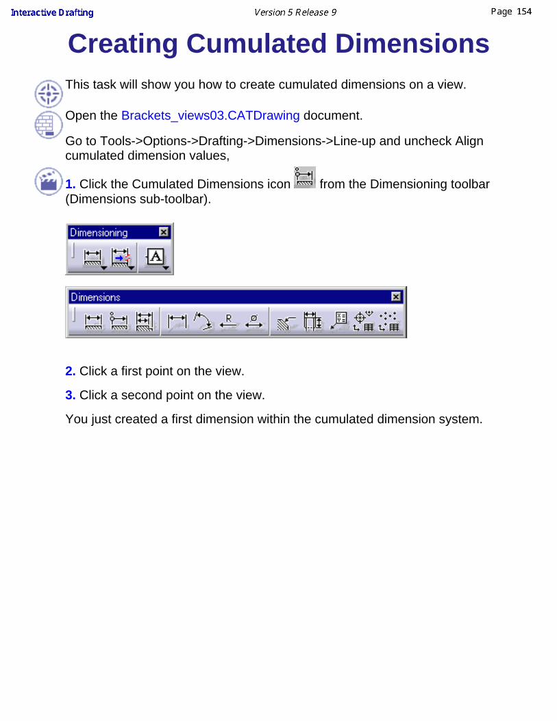
Creating Cumulated DimensionsThis task will show you how to create cumulated dimensions on a view.
Open the Brackets_views03.CATDrawing document.
Go to Tools->Options->Drafting->Dimensions->Line-up and uncheck Aligncumulated dimension values,
1. Click the Cumulated Dimensions icon from the Dimensioning toolbar(Dimensions sub-toolbar).
2. Click a first point on the view.
3. Click a second point on the view.
You just created a first dimension within the cumulated dimension system.

4. Click a third point on the view.
You now created a second cumulated dimension in the system.
You can create as many cumulated dimensions as desired.

Note that if you move one dimension line as you create a cumulated dimension,all the lines will move accordingly.
5. Click in the free space to end the cumulated dimension system creation.
If the cumulated dimensions are set with value oriented along dimension line, setthe parameter CUMLTxtReference parameter of your XXX.CATDrwStandardfile.
6. Go to Tools->Options->Drafting->Dimensions->Line-up and check Aligncumulated dimension values,
create the previous dimensions again but position them below the drawing:
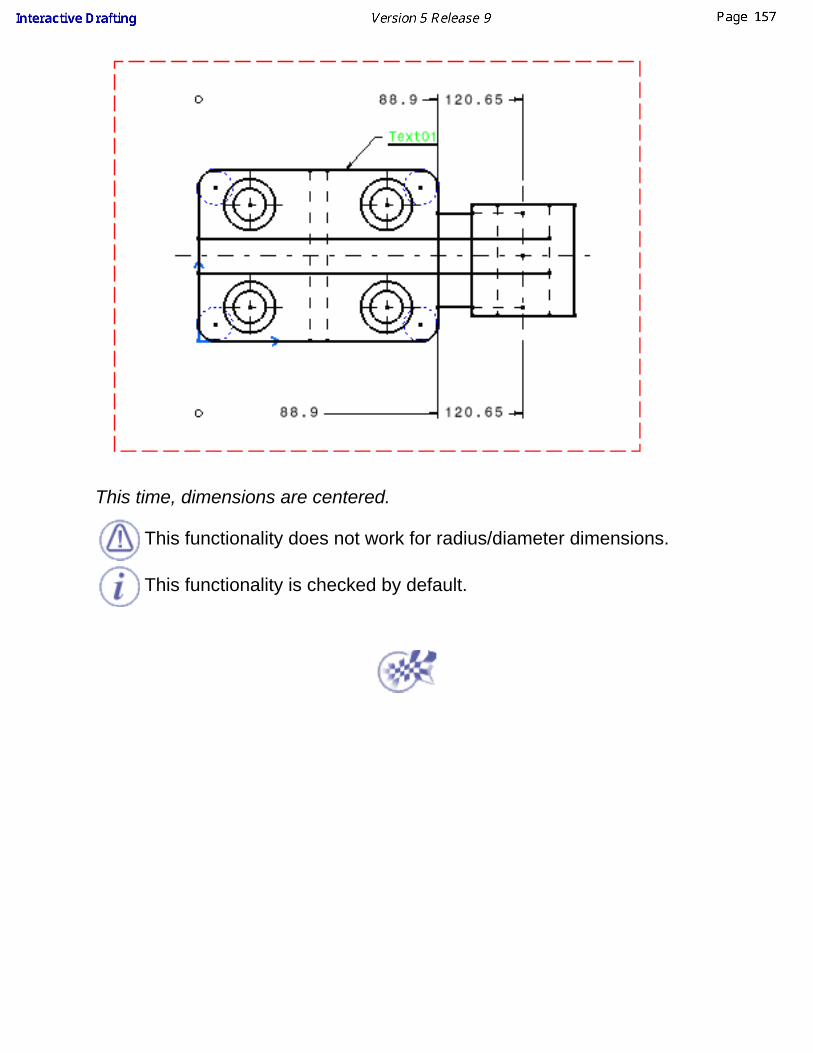
This time, dimensions are centered.
This functionality does not work for radius/diameter dimensions.
This functionality is checked by default.

Creating Stacked DimensionsThis task will show you how to create stacked dimensions on a view.
Stacked dimensions are parallel lines with a common extension line.
Open the Brackets_views03.CATDrawing document.
Go to Tools->Options->Mechanical Design->Drafting->Dimension->Line-Up anduncheck Align stacked dimension values.
1. Click the Stacked Dimensions icon from the Dimensioning toolbar(Dimensions sub-toolbar).
2. Click a first point on the view.
3. Click a second point on the view.
You just created a first dimension within the stacked dimension system.
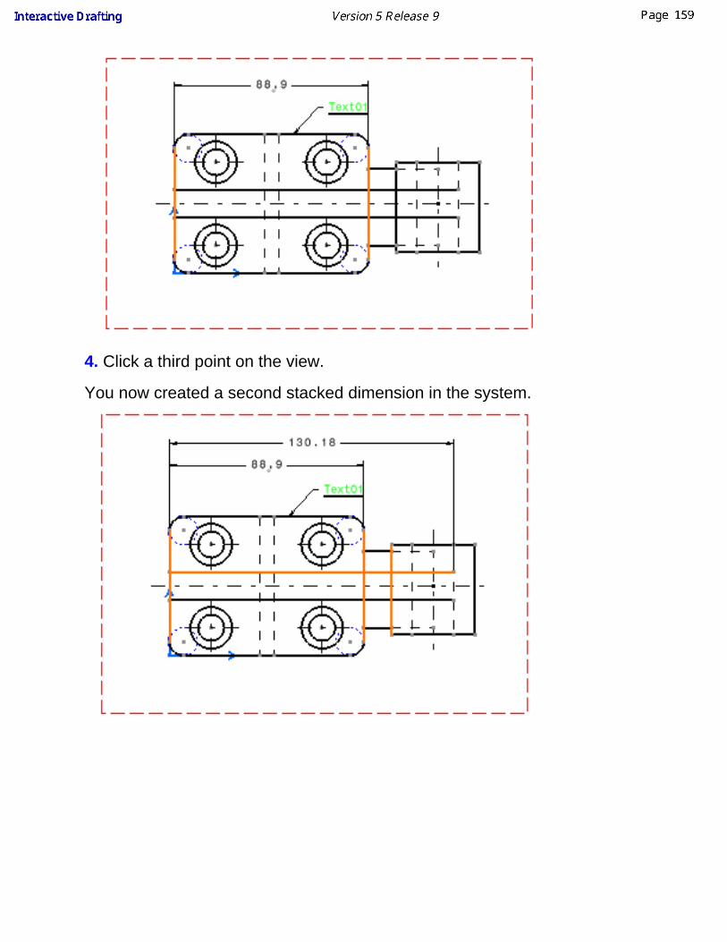
4. Click a third point on the view.
You now created a second stacked dimension in the system.

5. Click a fourth point on the view.
You now created a third stacked dimension in the system. Note that this stackeddimension inserted properly into the system.
You can create as many stacked dimensions as desired.
6. Click in the free space to end the stacked dimension creation.7. Go to Tools->Options->Drafting->Dimensions->Line-up and check Alignstacked dimension values,
create the previous dimensions again but position them below the drawing:
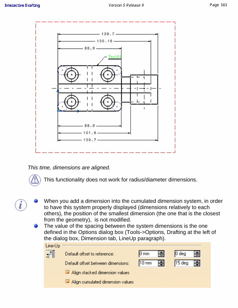
This time, dimensions are aligned.
This functionality does not work for radius/diameter dimensions.
When you add a dimension into the cumulated dimension system, in orderto have this system properly displayed (dimensions relatively to eachothers), the position of the smallest dimension (the one that is the closestfrom the geometry), is not modified.The value of the spacing between the system dimensions is the onedefined in the Options dialog box (Tools->Options, Drafting at the left ofthe dialog box, Dimension tab, LineUp paragraph).

As you create the dimensions in the system, you can modify move thewhole system. Still, you actually move the smallest dimension: all theother dimensions in the system are automatically aligned to this smallestdimension.
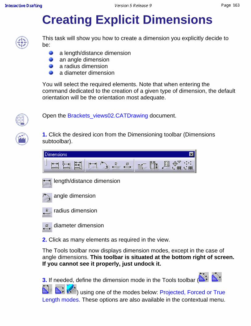
Creating Explicit DimensionsThis task will show you how to create a dimension you explicitly decide tobe:
a length/distance dimension an angle dimension a radius dimensiona diameter dimension
You will select the required elements. Note that when entering thecommand dedicated to the creation of a given type of dimension, the defaultorientation will be the orientation most adequate.
Open the Brackets_views02.CATDrawing document.
1. Click the desired icon from the Dimensioning toolbar (Dimensionssubtoolbar).
length/distance dimension
angle dimension
radius dimension
diameter dimension
2. Click as many elements as required in the view.
The Tools toolbar now displays dimension modes, except in the case ofangle dimensions. This toolbar is situated at the bottom right of screen.If you cannot see it properly, just undock it.
3. If needed, define the dimension mode in the Tools toolbar (
) using one of the modes below: Projected, Forced or TrueLength modes. These options are also available in the contextual menu.

Length/Distance Angle
Radius Diameter

For radius dimensions, you can activate Foreshortened option in thecontextual menu Properties -> Dimension Line.
It allows you to transform a radius dimension line into a foreshortenedradius dimension line. Then you can choose the text position (on longsegment or short segment), if segments will be parallel or convergent, theangle value, the ratio value (short segment/long segment), and the pointscale value.

Generating a Holes DimensionsTable
This task will show you how to generate a Holes and Center Lines DimensionsTable (containing diameter and center coordinates).
Open the alesage.CATDrawing document.
1. Select one or more holes and center lines (only center lines not associated witha hole) in the drawing.
2. Click the Hole Dimension Table icon on the Dimensioning toolbar to launchthe table creation command.

3. The Axis system and tableparameters dialog box is displayed.
Axis system:Indicate the holes coordinates2D reference axis system. Inthis example, click on the vieworigin (you can also select twolines or click anywhere in thedrawing, or enter the origincoordinate). Two reference axis appear:
You can rotate or flip theaxis using the Fliphorizontally and Flipvertically icons and chooseto represent the axissystem by checking theCreate representation box.Title: Type the table title.Columns:
Choose a label (A, B, C... or 1, 2, 3...). If you want column
numbering to start with values other than A or 1, click the icon and specify the start value. Select and name the column to display.
Table format:Check Transpose table to invert columns and rows.Check Sort table content to sort the table elements.

4. Choose 2D reference axis system for the axis system from the associateddrop-down list.
5. Type the table name in the Title field.
6. Select Label: A, B, C from the Column drop-down list (you can also choose theIndex naming mode) to give a label to the selected points in the drawing.
7. Check X, Y and Diameter to havefour columns corresponding to thehole labels and to the Cartesiancoordinates. Then enter a title for eachcolumn.
8. Check Transpose table to invert columns and rows in the table.
9. Check Sort table content and then
click the icon to define the sortingparameters.
10. To sort the table by descending Xcoordinates, choose X in the Sort bycombo box, and select Descending.Then, click Close.
11. Click OK to validate your settings and then click in the drawing to define thelocation of the table. The table is generated.


Creating a Points Coordinates TableThis task will show you how to create a table containing coordinates of pointsfrom 2D and 3D.
Open the PointSketch.CATDrawing document.
1. Multi-select the points on one of the views or on all views.
2. Click the Coordinate Dimension Table icon on the Dimensioning toolbar tolaunch the table creation command.

3. The Axis system and tableparameters dialog box is displayed.
Axis system:You can choose to use the 2Daxis system. It can be eitherthe one of the view oruser-defined. In this case, itcan be defined interactively byeither:
indicating a point byclicking in the view,selecting a point,selecting two lines.
Or it can be defined bytyping the origincoordinates in the X andY fields.
You can rotate or flip theaxis using the Fliphorizontally and Flipvertically icons andchoose to represent theaxis system by checkingthe Create representationbox.
Or you can choose to usethe 3D axis system. Inthis case, it is theabsolute axis of the 3Dmodel, or, if the model isa single part, a local axis.Title: Type the table title.

Columns:Choose a label (A, B,C... or 1, 2, 3...). If youwant column numberingto start with valuesother than A or 1, click
the icon andspecify the start value. Select and name thecolumn to display,
Table format:Check Transpose tableto invert columns androws.Check Sort tablecontent to sort the tableelements.
4. Choose Axis system.1 for the axis system from the associated drop-down list.
5. Type the table name in the Title field.
6. Select Label: A, B, C from the Column drop-down list (you can also choosethe Index naming mode) to give a label to the selected points in the drawing.
7. Check X, Y and Z to create fourcolumns corresponding to the pointslabels and to the Cartesiancoordinates. Then enter a title foreach column in the associated field.
8. Check Transpose table to invert columns and rows in the table.
9. Check Sort table content and click
the icon to define the sortingparameters.
10. To sort the table by descending Xcoordinates, choose X in the Sort bycombo box, and select Descending.Then, click Close.
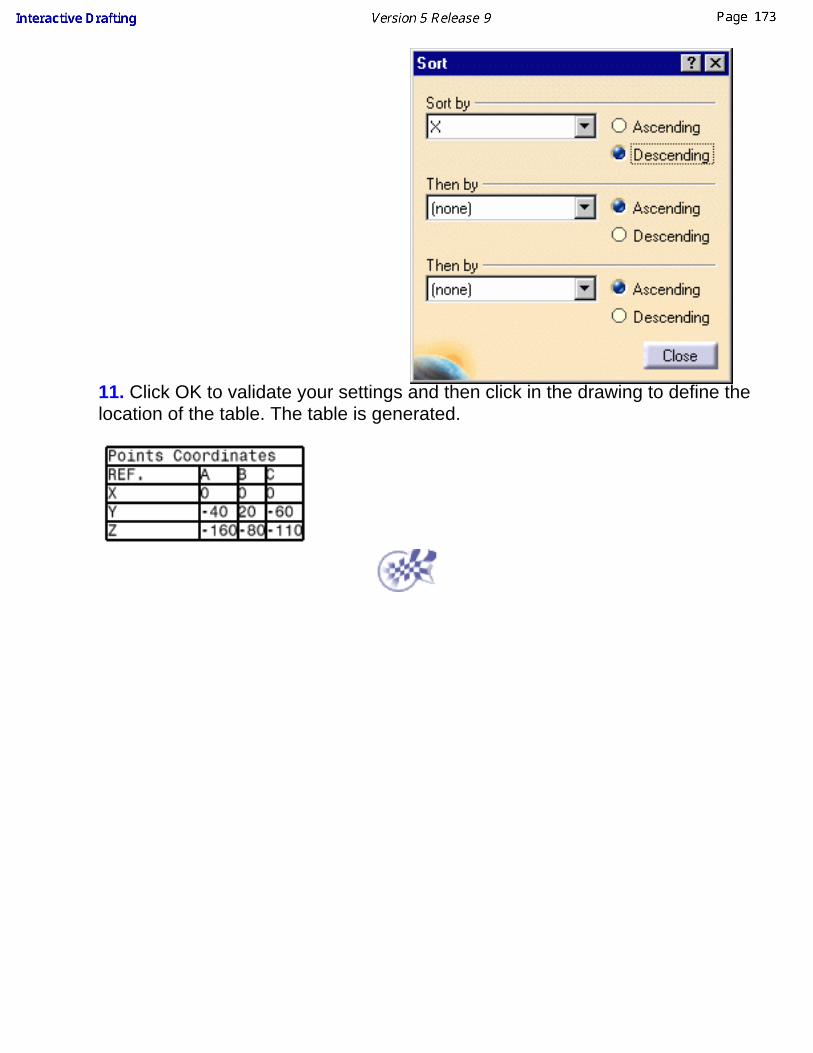
11. Click OK to validate your settings and then click in the drawing to define thelocation of the table. The table is generated.

Creating Chamfer DimensionsThis task will show you how to create a chamfer dimension.
Open the IntDrafting_Dim_Chamfer.CATDrawing document.
1.
Click the Chamfer Dimension icon from the Dimensioning toolbar (Dimensions subtoolbar).
2. In the toolbar Tools, you can choose:
The format of the dimension:Length x Length, in the example 19,1 x 19,1Length x Angle, in this example 19.1 x - 46°84'8"Angle x Length, in this example - 46°84'8" x 19.1Length 19,1.
The representation mode:
One symbol
Two symbols
Choose Length x Length format and one symbol mode .Text, dimension and graphic Properties Toolbars settings are taken into account duringcreation,all settings defined in Tools->Option->Mechanical Design->Drafting (dimension and manipulators tabs) are taken into account during creation.
3.
Select the element to be dimensioned.
4.
Select a reference line or surface.
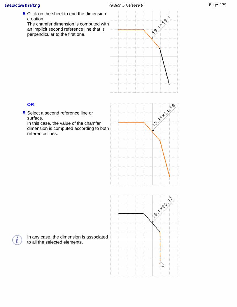
5.
Click on the sheet to end the dimensioncreation.The chamfer dimension is computed withan implicit second reference line that isperpendicular to the first one.
5.
OR
Select a second reference line orsurface.In this case, the value of the chamferdimension is computed according to bothreference lines.
In any case, the dimension is associatedto all the selected elements.

When creating a chamfer dimension on a generated view, all elements you select must belong to aplane which is normal to the section plane.

Creating Associative ThreadDimensions
This task will show you how to create associative thread dimensions.
Open the intthread.CATDrawing document.
1.
Click the ThreadDimension icon
from the
Dimensioningtoolbar(Dimensionssubtoolbar).
2.
Select the thread to be dimensioned in the front view. The diameter dimensionappears.
3.
Click the ThreadDimension icon
.

4.
Select the twolinesrepresenting thethread to bedimensioned inthe section view.
Two dimensionsappear:
the threaddiameter,the threaddepth.
The dimension prefix (M in this example) is issued from the threadstandard defined when creating the hole in the 3D Part. In the top views you can modify threads dimensions orientation.

Lining up Dimensions (Free Space)This task will show you how to line up the following dimensions relative to a point inthe free space:
Length dimensionsDistance dimensionsRadius dimensionsDiameter dimensionsAngle dimensions
In other words, you are going to organize dimensions into a system with a linearoffset. The offset will align the dimensions to each others as well as the smallestdimension to the reference element.Open the LineUp_Dimensions01.CATDrawing document.
1. Select the dimensions to be lined up.
2. Right click and select Line-up option from the contextual menu
or click on the Line-Up icon .
You can also select Tools->Positioning->Line-up item from the menu bar.
3. Click anywhere on the drawing.

The Line Up dialog box appears:
4. Enter the desired Linear offset value. For example, 20 mm.
5. Click the Only organize into systems option.
6. Click OK to validate.
The position of the smallest system dimension will not be modified. The stackedsystem dimensions will be aligned to this smallest dimension.
The dimensions are now aligned:
When you click in the free space, the linear offset between the smallest dimensionand the reference is automatically set to 0 value. The space between twodimensions will be the space defined in the Options dialog box (Tools->Options,Mechanical Design ->Drafting at the left of the dialog box, Dimension tab, Line Upparagraph). See Dimension Creation in the Infrastructure User's Guide for moredetails.

Lining up Dimensions (Reference)This task will show you how to line up the following dimensions according to agiven reference:
Length dimensionsDistance dimensionsRadius dimensions Diameter dimensions Angle dimensions
Open the LineUp_Dimensions02.CATDrawing document.
1. Go to Tools->Options->Mechanical Design->Drafting->Dimensions
the offset you can set in this dialog box correspond to :
2. Select the dimensions to be lined-up.
3. Right click and select Line-up item from the contextual menu.

You can also select the select Tools->Positioning->Line-up item from the menubar.
4. Select the element that will be used as reference for positioning dimensions.See the example above.
The Line Up dialog box appears. You can see that the default values are theones set in Tools Options menu (see step 1).
5. Enter the required offset values in the Line Up dialog box and, if needed,deactivate the Only organize into systems option.
The smallest dimension positions with respect to the element selected andoffsets by 20 mm. And offset between dimension is equal to 30mm.
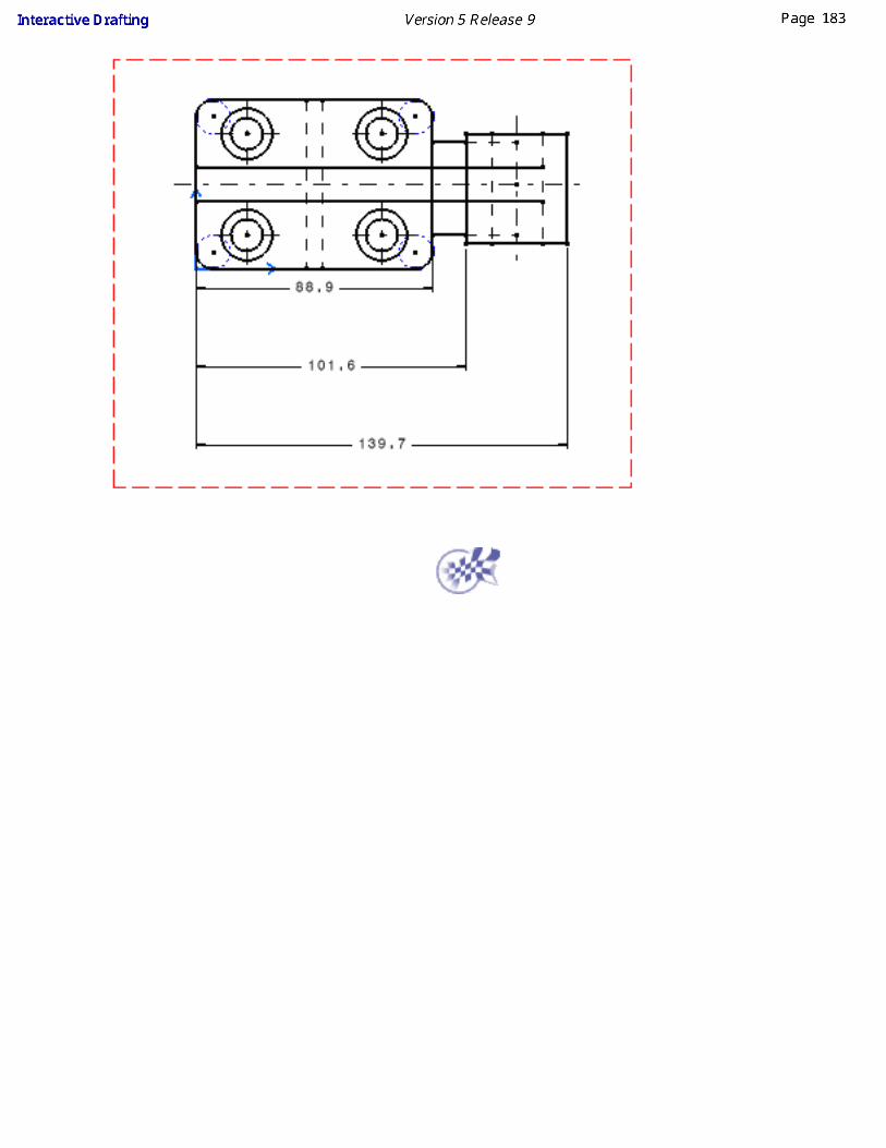
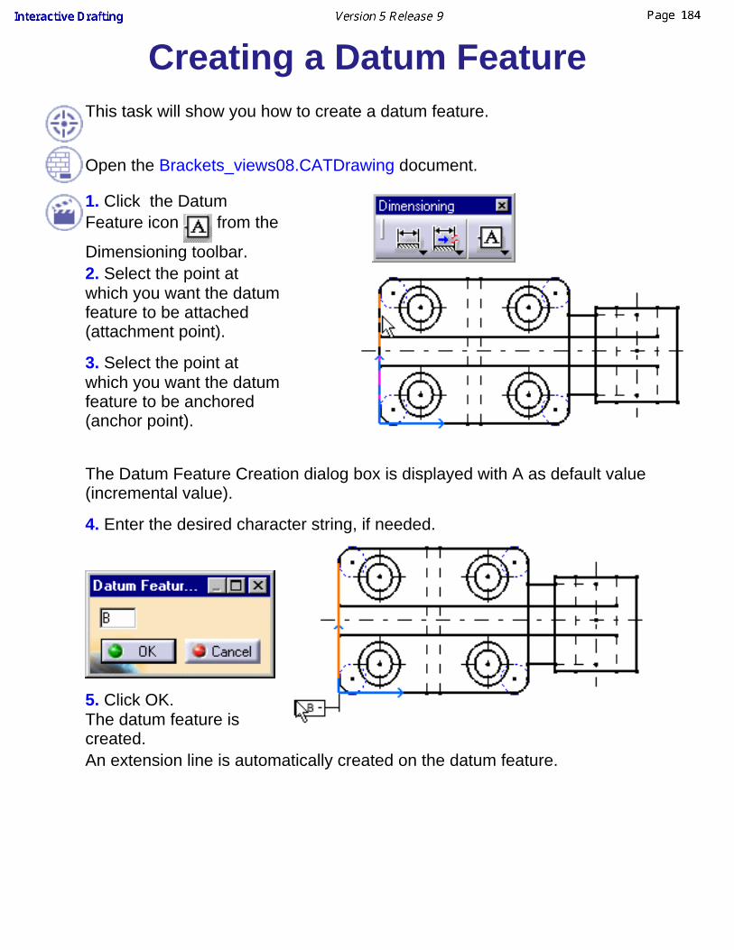
Creating a Datum FeatureThis task will show you how to create a datum feature.
Open the Brackets_views08.CATDrawing document.
1. Click the DatumFeature icon from the
Dimensioning toolbar.2. Select the point atwhich you want the datumfeature to be attached(attachment point).
3. Select the point atwhich you want the datumfeature to be anchored(anchor point).
The Datum Feature Creation dialog box is displayed with A as default value(incremental value).
4. Enter the desired character string, if needed.
5. Click OK.The datum feature iscreated.An extension line is automatically created on the datum feature.

The character string that is edited in the Datum Feature Creation dialogbox is simultaneously previewed on the drawing.When you create more than one datum feature, the character string of thisdatum feature is automatically incremented.To change Datum Feature ANSI representation into ASME representation,change the TXTDatumMode parameter of your XXX.CATDrwStandardfile (see Managing Standards):
ASME
TXTDatumMode = 1(Normal)
ANSI
TXTDatumMode = 2(Flag)

Modifying a Datum FeatureThis task shows you how to modify a datum feature by editing it.
Open the Brackets_views03.CATDrawing document. Create a datum feature.
1.Double-clickthe datumfeature youwant tomodify.
The DatumFeatureModificationdialog box isdisplayed.
2. Modify thedatum featurevalue. Forexample,enter Binstead of A.
3. Click OK.
4. Click in thefree space orselectanother icon.
The datumfeature ismodified.

Creating a Geometrical ToleranceThis task shows you how to create a geometric tolerance (annotation).You can also copy the parameters of an existing geometric tolerance. You can set text propertieseither before or after you create the text.
Creating a Geometrical ToleranceLeader orientationGeometrical tolerance orientation
Creating a Geometrical ToleranceOpen the Brackets_views03.CATDrawing document.
1. Click the Geometric Tolerance icon from the Dimensioning toolbar (Tolerancingsubtoolbar).
2. Select an element (geometry, dimension, text or a point) or click in the free space.Selecting a point in the free space allows you to position the end of the leader.If you select a point in the free space, the base-mark symbol will be a small balloon.If you select an element, the base-mark symbol will be an arrow. Note that you can modify thissymbol by editing the annotation leader.
3. Click to position the geometric tolerance.
The Geometric Dimensioning And Tolerancing Parameters dialog box appears.
4. Enter the desired values (geometric characteristic for Line 1 and/or Line 2, tolerance and datumvalues).To move to the next field, press Enter or Tab each time you enter a value in one text field.The geometric tolerance is updated as you define values for each field.
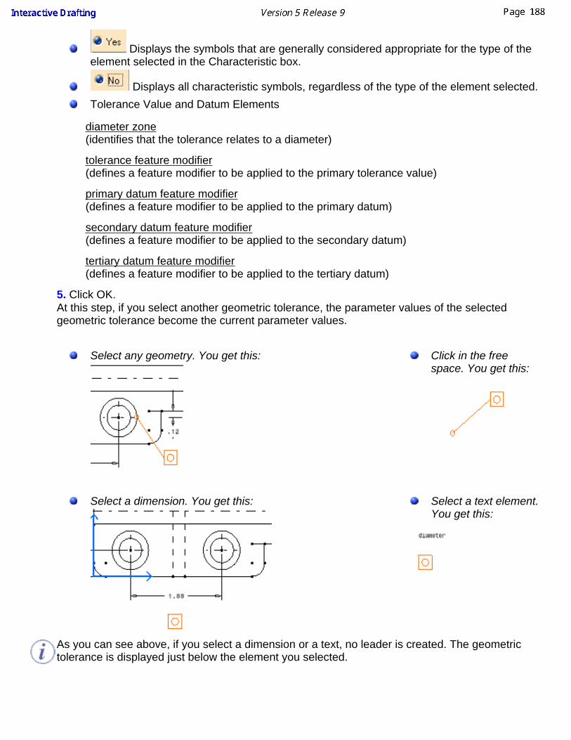
Displays the symbols that are generally considered appropriate for the type of theelement selected in the Characteristic box.
Displays all characteristic symbols, regardless of the type of the element selected.Tolerance Value and Datum Elements
diameter zone(identifies that the tolerance relates to a diameter)
tolerance feature modifier(defines a feature modifier to be applied to the primary tolerance value)
primary datum feature modifier(defines a feature modifier to be applied to the primary datum)
secondary datum feature modifier(defines a feature modifier to be applied to the secondary datum)
tertiary datum feature modifier(defines a feature modifier to be applied to the tertiary datum)
5. Click OK.At this step, if you select another geometric tolerance, the parameter values of the selectedgeometric tolerance become the current parameter values.
Select any geometry. You get this: Click in the free
space. You get this:
Select a dimension. You get this: Select a text element.You get this:
As you can see above, if you select a dimension or a text, no leader is created. The geometrictolerance is displayed just below the element you selected.

Leader orientationThe leader first segment can be perpendicular to the element associated with the leader. For this,you can:
go to tools -> options-> drafting -> annotations tab and check Geometrical tolerance inAnnotation Creation -> Apply snapping toor if this option is not activated hold shift key before clicking in the drawing to position thetolerance (previous scenario, step 3).
Geometrical tolerance orientationThe tolerance can be vertical. For this, hold the ctrl key before clicking in the drawing to positionthe tolerance (previous scenario, step 3).

Modifying Geometrical TolerancesThis task shows you how to modify a geometrical tolerance.
Open the Brackets_views03.CATDrawing document. Create a geometricaltolerance.
1. Double-click thefeature control youwant to modify.
The Geometric Dimensioning & Tolerancing Parameters dialog box displays.
2. Modify any desired value from the Geometric Dimensioning & TolerancingParameters dialog box.
3. Click OK.

4. Click in the freespace to validate thegeometrical dimensionmodification.
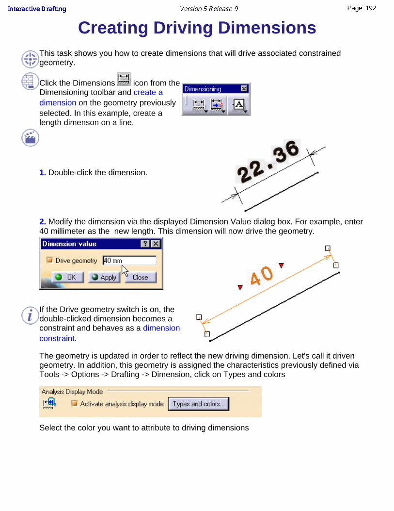
Creating Driving DimensionsThis task shows you how to create dimensions that will drive associated constrainedgeometry.
Click the Dimensions icon from theDimensioning toolbar and create adimension on the geometry previouslyselected. In this example, create alength dimenson on a line.
1. Double-click the dimension.
2. Modify the dimension via the displayed Dimension Value dialog box. For example, enter40 millimeter as the new length. This dimension will now drive the geometry.
If the Drive geometry switch is on, thedouble-clicked dimension becomes aconstraint and behaves as a dimensionconstraint.
The geometry is updated in order to reflect the new driving dimension. Let's call it drivengeometry. In addition, this geometry is assigned the characteristics previously defined viaTools -> Options -> Drafting -> Dimension, click on Types and colors
Select the color you want to attribute to driving dimensions
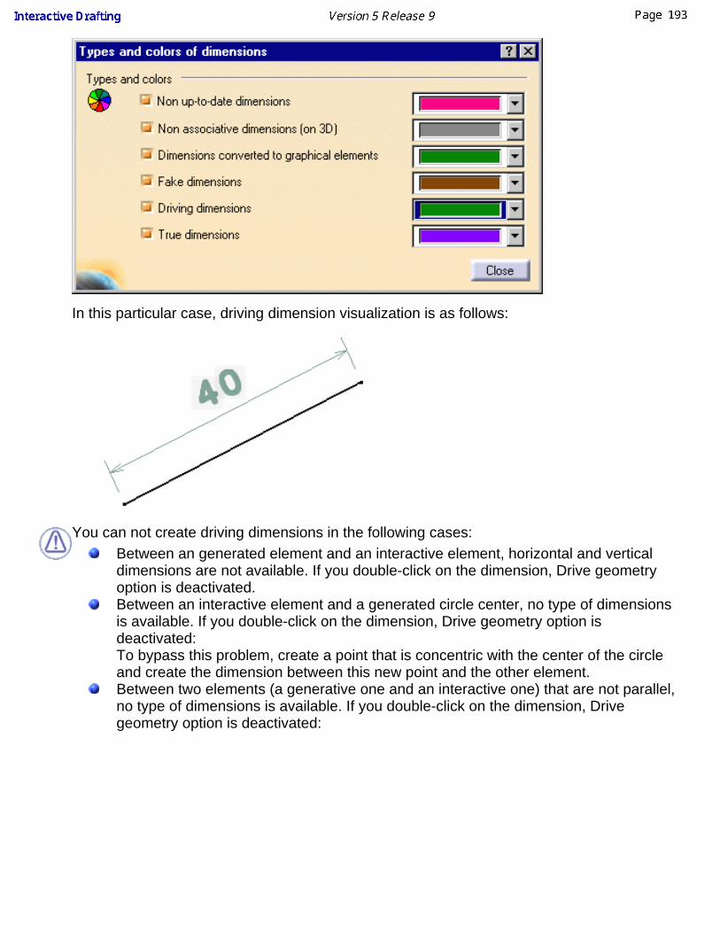
In this particular case, driving dimension visualization is as follows:
You can not create driving dimensions in the following cases:Between an generated element and an interactive element, horizontal and verticaldimensions are not available. If you double-click on the dimension, Drive geometryoption is deactivated.Between an interactive element and a generated circle center, no type of dimensionsis available. If you double-click on the dimension, Drive geometry option isdeactivated: To bypass this problem, create a point that is concentric with the center of the circleand create the dimension between this new point and the other element.Between two elements (a generative one and an interactive one) that are not parallel,no type of dimensions is available. If you double-click on the dimension, Drivegeometry option is deactivated:

To bypass this problem, create a point that will be coincident with line A and line B atthe same time and create the dimension between this new point and the otherelement.Between two semicircles (apart from dimensions between the semicircles centers). Ifyou double-click on the dimension, Drive geometry option is deactivated:
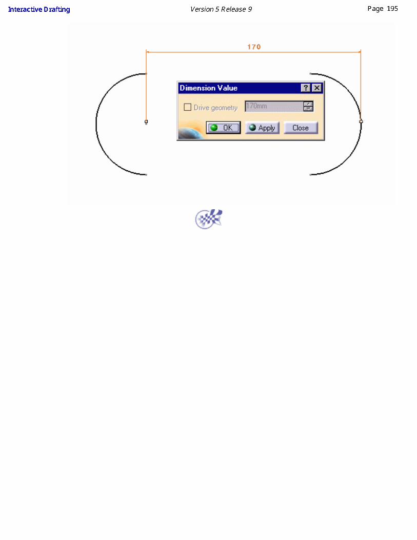

Setting Relations Between Dimensional ConstraintsThis task shows you how to set constraints between dimension using formulas. As a result, if you modify one ofthese dimensions (the driving dimension), all the other dimensions as well as the geometry will be modifiedaccordingly.
Open the Brackets_views04.CATDrawing document.
1. Click the Formula icon from the Standards toolbar.
The Formulas dialog box appears.
You will now select, one after the other, the dimensions to be constrained and then enter in the dialog box theformulas to be used.

2. Select a first dimension (1).
3. Press the Add Formula switch in the Formulas dialog box.
The Formula Editor dialog box appears.
4. Select a second dimension (3) and add "/4". Then, click OK (Formula Editor dialog box).
5. Select a first dimension (2).
6. Press the Add Formula switch in the Formulas dialog box.
The Formula Editor dialog box appears.
7. Select a second dimension (3) and add "*3 /4". Then, click OK (Formula Editor dialog box).
8. Select a first dimension (4).
9. Press the Add Formula switch in the Formulas dialog box.
The Formula Editor dialog box appears.
10. Select a second dimension (1) and then, click OK (Formula Editor dialog box).

11. Select a first dimension (5).
12. Press the Add Formula switch in the Formulas dialog box.
The Formula Editor dialog box appears.
13. Select a second dimension (2) and then, click OK (Formula Editor dialog box).
14. Click OK ( Formulas dialog box).
Note that the specification tree is modified accordingly.
15. Double-click the dimension to be set as driving dimension (3).
The Dimension Value dialog box appear.
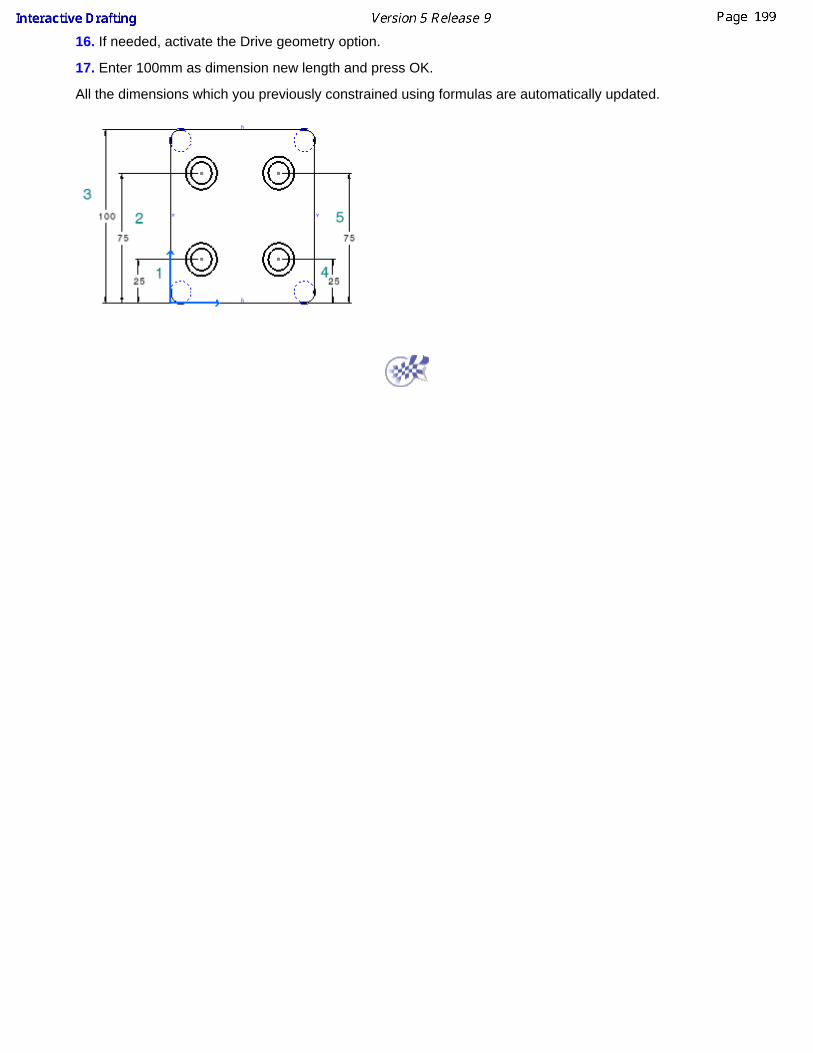
16. If needed, activate the Drive geometry option.
17. Enter 100mm as dimension new length and press OK.
All the dimensions which you previously constrained using formulas are automatically updated.
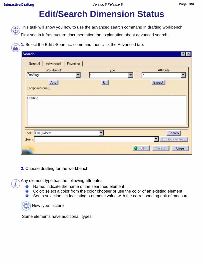
Edit/Search Dimension StatusThis task will show you how to use the advanced search command in drafting workbench.
First see in Infrastructure documentation the explanation about advanced search.
1. Select the Edit->Search... command then click the Advanced tab:
2. Choose drafting for the workbench.
Any element type has the following attributes:Name: indicate the name of the searched elementColor: select a color from the color chooser or use the color of an existing elementSet: a selection set indicating a numeric value with the corresponding unit of measure.
New type: picture
Some elements have additional types:

Type Additional attributes Value to select or to key inBalloon Part name name of the searched elementDatum Feature Reference name name of the searched elementDatum Target Reference name name of the searched element
Size size indicated in the searched elementDimension Type type of dimension (angle, diameter,
radius, length, etc.) searched
value dimension value searched
Non associative on3D Yes/No
Not updatable Yes/No
Fake Yes/No
Driving dimension Yes/No
True Yes/No
Geometrical tolerance value tolerance value searched
typetolerance type (circularity,concentricity, flatness, parallelism,etc.) searched
Text having attribute links Yes/Notext string text string searched
3. Select an operating sign in the first combo box.4. Select (if there is a combo box) or key in the value you are looking for.

PropertiesThis section discusses how to quickly access and edit information on 2D geometry,dress-up elements, annotations and dimensions in a single dialog box, provided youuse the Edit->properties command.
The data you can access (tabs) depends on the element you select. Note thatclicking the More switch gives you access to more tabs.
The tasks described in this section are listed in the following table.
Editing View Properties
Access and, if needed, edit view properties.Editing 2D geometry feature properties:
Access and, if needed, edit information on 2D geometry features(name and stamp).
Editing element graphic properties:Access and, if needed, edit graphic properties.
Editing annotation font properties:Access and, if needed, edit annotation font properties.
Editing text properties:Access and, if needed, modify text color, position and/or orientation.
Editing dimension text properties:Access and, if needed, edit dimension text properties.
Editing dimension value properties:Access and, if needed, edit dimension value properties.
Editing dimension tolerance properties:Access and, if needed, edit dimension tolerance properties.
Editing dimension extension line properties:Access and, if needed, edit dimension extension line properties.
Editing dimension line properties:Access and, if needed, edit information on dimension line properties.
Editing 2D component instance properties:Access and, if needed, edit 2D component instance properties.

Editing View PropertiesThis task explains how to edit view properties.
Open the PointSketch.CATDrawing document.
1. Right-click on the front view and select properties. Choose the View tab.
2.Choose your options.

Visualization and behaviorDisplay view frame: show/hide the view frame,Lock view: if you check this option, no more modification allowed in theview.Visual clipping: lets you reframe a view so as to display only part of it.
Scale and Orientation
Angle: the angle between the view and the sheet,Scale: the scale of the view.
Dressup
Choose the dressup elements you want to display in the view (for generatedviews only):
Hidden lines, Center line, 3D spec, Axis, Thread, 3D Wireframe, 3D Colors, Fillets: you can choose to view Boundaries, Symbolic, Original Edges,Projected Original Edges.
Boundaries: thin lines, representing the mathematical limits of thefillets.Symbolic: original edges, projected in a direction that is normal toeach corresponding surface. Original Edges: original edges, at the intersection of the twosurfaces joined by the fillet.Projected Original Edges: original edges, projected on filletsurfaces in the direction of the view projection.
3D Points: projects points from 3D (no construction elements). You canchoose from the following options:
3D symbol inheritance: keeps the symbol from the 3D.Symbol: displays the symbol you choose from the drop-down list.
View Name
Allows you to modify the name of the view. Among other things, you can create aformula for the view name.

Editing 2D Geometry FeatureProperties
This task shows you how to access and, if needed, edit information on 2Dgeometry features (name and stamp).
Open the Brackets_views03.CATDrawing document.
1. Select a 2D element on the CATDrawing you opened.
2. Select the Edit->Properties command and click the Feature Properties tab.
You can also right click the 2D element and then select the Properties commandfrom the displayed contextual menu.
3. If needed, click the More switch.
4. Enter a new name for the element in the field.The information displayed concerns the creation of the elements.
5. Click the Graphic Tab, Lines and Curves option, Pickable option and Layersoptions are available. For settings, see Editing Element Graphic Properties.

5. Click OK.

Editing Element Graphic PropertiesThis task explains how to access and, if needed, edit graphic properties.
Open the Brackets_views03.CATDrawing document.
1. Select a 2D element on the CATDrawing you opened.
2. Select the Edit-> Properties command and click the Graphic tab.
You can also right click the current element and then select the Propertiescommand from the displayed contextual menu.
3. If needed, click the More switch.
4. If needed, modify the available options:
Fill:you can color the selected element and set the filling transparency.
Edges:it allows you to define edges colors, thickness and the type of line(dotted, dashed, etc.), see Graphic Properties Toolbar.

Lines and Curves: it allows you to define lines and curves colors, thickness and thetype of line (dotted, dashed, etc.), see Graphic Properties Toolbar.
Show, Pick and Layers:you can choose if the element will be shown or not (check/uncheckShown option)you can activate or deactivate Pickable mode, if you uncheck itgeometry will not be selectable anymore, see Pick/No Pick mode.you can choose a layer for the selected geometry.
5. Click OK.
For more information on graphic properties, please refer to Infrastructure User'sguide.
Pick/No Pick modeWhen you create elements using the No Pick mode (Pickable optionunchecked),
If you want to make one or several elements pickable back again, performas follows:
1. Select Edit -> Search from the menu bar and select the element(s)to be modified from the Search dialog box.
2. Select Edit -> Properties option from the menu bar and check thePickable option from the Properties dialog box.If you want to make all the elements on a sheet or in a view pickable backagain, perform as follows:
1. Click the sheet or the view(s) to be applied the Pick mode from thespecification tree.
2. Select the Force Pick Mode option from the contextual menu.
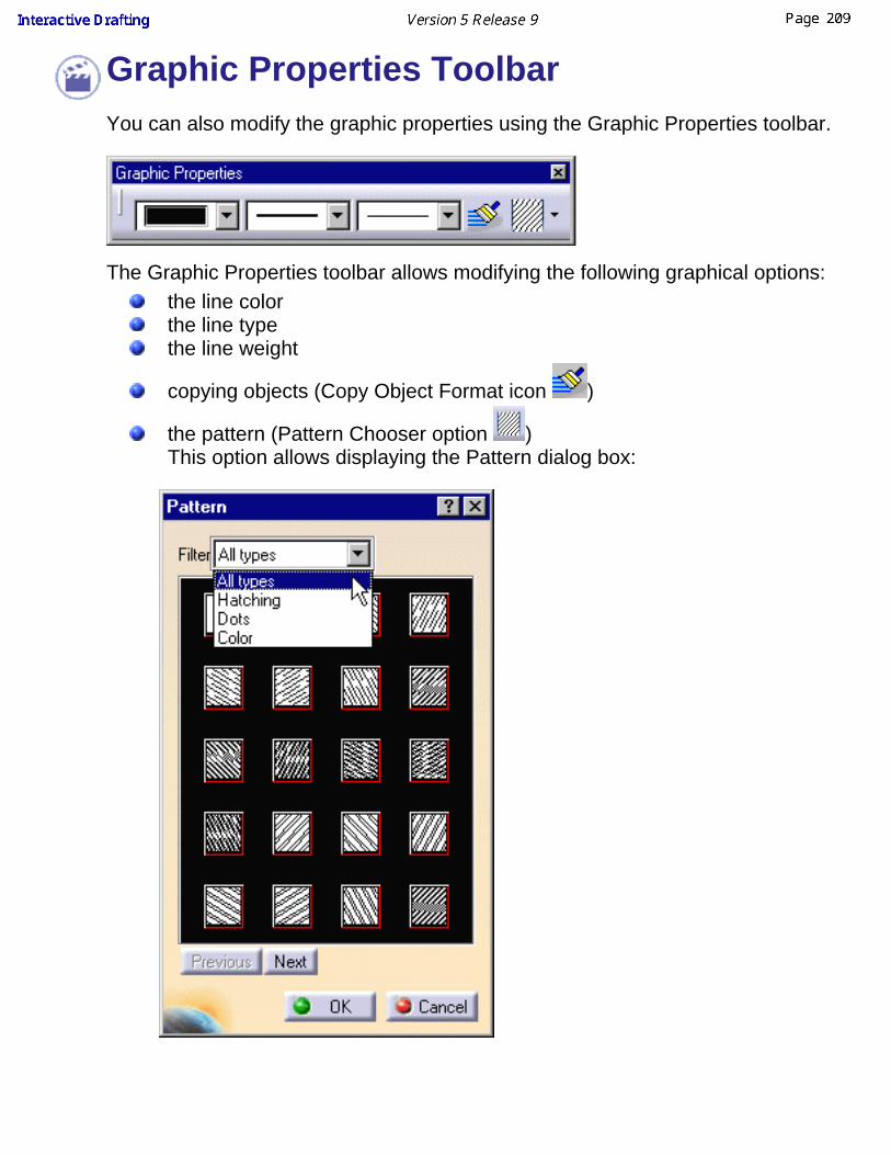
Graphic Properties ToolbarYou can also modify the graphic properties using the Graphic Properties toolbar.
The Graphic Properties toolbar allows modifying the following graphical options:the line colorthe line typethe line weight
copying objects (Copy Object Format icon )
the pattern (Pattern Chooser option )This option allows displaying the Pattern dialog box:

Care when you assign graphical attributes to a line (for example, make it thickand red).When you turn this red thick line into a construction line (from the contextualmenu: Object.Line -> Definition..., Construction line option in the Line Definitiondialog box), the line will become a dotted gray line. Even though you thendecide to make it a standard line back again (un-checking the Construction lineoption), the "red" and "thickness" attributes will not be assigned to the line. Theline will be assigned its original attributes.

Editing Annotation Font Properties This task explains how to access and, if needed, edit annotation font properties.
Open the Brackets_views03.CATDrawing document. Create a free text on theCATDrawing you opened.
1. Double-click the text to switch it to edit mode.
2. Select the whole text (you can also select only part of the text) and right-click it.
3. Click Properties in the menu that appears. The Properties dialog box appears.
Another way of doing this is by simply selecting the text and then selectingProperties from the Edit menu.
4. Click the Font tab.
Clicking the More button will display extra options, if any are available.
5. Modify the available options as required.

Font, Style, Size, Underline and Color: choose the font, size, style and colorof the text, and underline it. Attributes: draw a line through (Strikethrough) or above (Overline) theselected text, and make it superscript or subscript.
You can either underline or overline a text, but you cannot do both.
Character:
Ratio: modify character size.Slant: modify character slant (for italic text, slant=15 deg).Spacing: change the spacing between characters.Pitch: set a fixed or a variable pitch. As an example, create the freetext "Tools" and apply the font ROM1.
Fixed Pitch Variable Pitch

The Slant and Pitch options are available only for stroke fonts.
6. Click OK.
For more information on font properties, please refer to the Infrastructure User'sguide.

Editing Text PropertiesThis task explains how to access and, if needed, modify text color, positionand/or orientation. You will also learn how to specify the text display mode.Open the Brackets_views03.CATDrawing document. Create a free text.
When you create a free text, the anchor point is the point you click in free spaceto define a location for the free text.
1. Select an annotation (whatever the type) on the CATDrawing you opened.
2. Select the Edit-> Properties command and click the Text tab.
You can also right click on the current element and then select the Propertiescommand from the displayed contextual menu.
3. If needed, click the More switch button.
4. Modify the available options as required.

Display Units: In a text containing parameters with units, displays theseunits.Apply scale: Applies the scale of the view or of the 2D referencecomponent scale to the display of the text.Back Field: Aligns superscript and subscript texts above one another.Superscript: Increase or decrease the values for the superscript texts inthe Offset and Size fields to set the offset and size.Subscript: Increase or decrease the values for the subscript texts in theOffset and Size fields to set the offset and size.Display: Specifies a display mode for the text.
Frame: you can choose a frame type for the selected text that is to sayrectangle, triangle, circle, etc. You can specify the color, line thickness andtype of line for the frame in the associated fields.

Position: Anchor Point: you can change the text position in relation to theanchor point.Justification: you can specify a justification for the text: left, centeror right.X, Y: you can modify anchor point coordinates.Anchor Line: it allows you to position the anchor line to thecharacter Top and Bottom or to the character Cap or Base.
Line Spacing Mode: you can choose the spacing mode between toline of characters. As an example, create the following free text:
and select base to cap option in the combo box. The spacingbetween the two lines will be between the base of first linecharacters and cap of second line characters:
Line spacing: you can increase or decrease the spacing betweentwo lines of characters.Word wrap: allows you to wrap the text in a width you specify.
Orientation: You can select a text orientation reference, the textorientation. If you choose Fixed Angle for Orientation, you can define theorientation angle according to the chosen reference. Use the Mirroringoption to apply a symmetry to the selected text. Check the Auto Flip optionto automate the text flip, it will force the text to be in readable position.Options:
5. Click OK.
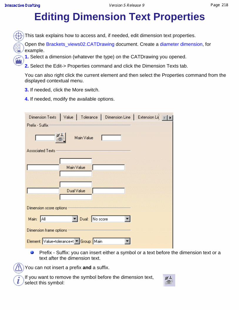
Editing Dimension Text PropertiesThis task explains how to access and, if needed, edit dimension text properties.
Open the Brackets_views02.CATDrawing document. Create a diameter dimension, forexample.1. Select a dimension (whatever the type) on the CATDrawing you opened.
2. Select the Edit-> Properties command and click the Dimension Texts tab.
You can also right click the current element and then select the Properties command from thedisplayed contextual menu.
3. If needed, click the More switch.
4. If needed, modify the available options.
Prefix - Suffix: you can insert either a symbol or a text before the dimension text or atext after the dimension text.
You can not insert a prefix and a suffix.
If you want to remove the symbol before the dimension text,select this symbol:

Associated Texts: you can insert texts before, after, below and above the main and thedual value.
Dimension texts positioning:
Dimension score options: you can choose to score only the value, all dimension textsor not to score (for Main Value and/or Dual Value).Dimension frame options: you can choose to include in the frameValue+tolerance+texts or Value+tolerance or Value for Main Value, Dual Value orboth.
5. Click OK.
Editing Dimension Value PropertiesThis task explains how to access and, if needed, edit dimension value properties.
Open the Brackets_views03.CATDrawing document. Create a diameterdimension, for example.
1. Select a dimension (whatever the type) on the CATDrawing you opened.
2. Select the Edit-> Properties command and click the Value tab.
You can also right click the current element and then select the Propertiescommand from the displayed contextual menu.
3. If needed, click the More switch.
4. If needed, modify the available options.

Dimension Type: check Driving if you want projected dimensions to drivegeometry.
If you want to key in a value for the driving dimension, you must close Propertiesdialog box, double-click the dimension in the drawing, check Drive geometry andkey in a value.

Value Orientation: you can choosethe value orientation reference (Screen, View or Dimension Line),the value orientation (Parallel, Perpendicular or Fixed Angle),the orientation angle if Fixed Angle is selected in orientation.
Dual Value: you can show dual value checking Show dual value optionand choose its location.Format: you can set Main value and Dual value format.
Description: select a type of format.Display: choose to display one, two or three factors.Format: choose fractional or decimal format.Precision: select the value precision.
For chamfer, you can set Description, Display and Format in chamfer tab.
Fake Dimension: check this option to display fake dimensions, you canchoose to display numerical or alphanumerical fake dimensions.
Text limitation: eight characters.If you need to insert a text containing more than height characters:
let the dimension text blank (for this you can create a blank fakedimension),create an associated text.
5. Click OK.

Editing Dimension ToleranceProperties
This task explains how to access and, if needed, edit dimension toleranceproperties.Open the Brackets_views02.CATDrawing document. Create a diameterdimension, for example.
1. Select the diameter dimension.
2. Select the Edit-> Properties command and click the Tolerance tab.
You can also right click the current element and then select the Propertiescommand from the displayed contextual menu.
3. You can associate a tolerance to the selected dimension. In this example,choose ISOALPHA1 in Main Value.
4. Select a value in First value, the corresponding numerical value appears inUpper and lower value.
Dual Value (numerical or alphanumerical) is equal to Main Value (numerical oralphanumerical).
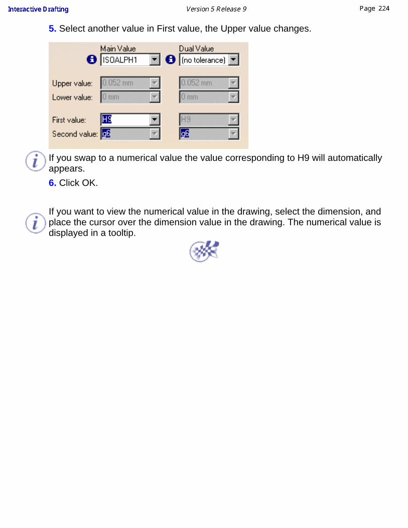
5. Select another value in First value, the Upper value changes.
If you swap to a numerical value the value corresponding to H9 will automaticallyappears.6. Click OK.
If you want to view the numerical value in the drawing, select the dimension, andplace the cursor over the dimension value in the drawing. The numerical value isdisplayed in a tooltip.

Editing Dimension Extension Line PropertiesThis task explains how to access and, if needed, edit dimension extension line properties.
Open the Brackets_views02.CATDrawing document. Create a diameter dimension, for example.
1. Select a dimension (whatever the type) on the CATDrawing you opened.
2. Select the Edit-> Properties command and click the Extension Line tab.
You can also right click the current element and then select the Properties command from thedisplayed contextual menu.
3. If needed, click the More switch.
4. If needed, modify the available options.
Extremities: it allows you to increase or decrease Extension Line Overrun and Blanking.

Overrun is the overrun minimum value. As an example, for a cumulated dimension (for ISOStandard):
you can increase the overrun size you can not decrease it below theminimum value
To set Cumulate dimension extension line length and text position, use the CUMLExtModeparameter in Managing Standards.
Graphism: you can define Extension Lines graphic properties, that is to saythe Extension Lines color,the Extension Lines thickness,to display or not each Extension Line.
Funnel: to insert a funnel, you must check this option. You can configure the funnel:the Height,the Angle,the Width,the funnel mode
External Funnel Mode Internal Funnel Modethe Funnel side allows you to apply funnel only on one extension line or both of them.
Funnelled dimension lines cannot be selected to be interrupted.
5. Click OK.

Editing Dimension Line PropertiesThis task explains how to access and, if needed, edit information on dimensionline properties.Open the Brackets_views02.CATDrawing document. Create a diameterdimension, for example.1. Select a dimension (whatever the type) on the CATDrawing you opened.
2. Select the Edit-> Properties command and click the Dimension Line tab.
You can also right click on the current element and then select the Propertiescommand from the displayed contextual menu.
3. If needed, click the More switch.
4. If needed, modify the available options.
You can apply different kinds of modifications between arrow symbol 1 andsymbol 2 on the condition the drawing was created from version 5 release 5 on.

Graphism: you can choosethe Representation:the Orientation of the dimension line,the Reference for the dimension line orientation,the Angle if Orientation value is dimension line and Referencevalue is fixed angle,the dimension line Thickness and Color.
Symbols: Shape: you can choose the dimension line shape (arrow, circle,plus, etc.).Color: you can choose the symbols color.Thickness: you can define the symbol thickness.Reversal: you can set the symbol orientation (inside or outside).
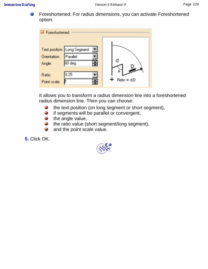
Foreshortened: For radius dimensions, you can activate Foreshortenedoption.
It allows you to transform a radius dimension line into a foreshortenedradius dimension line. Then you can choose:
the text position (on long segment or short segment), if segments will be parallel or convergent,the angle value,the ratio value (short segment/long segment), and the point scale value.
5. Click OK.

Editing 2D Component InstanceProperties
This task explains how to access and, if needed, edit information on instantiated2D component properties.Open the Position_Component03.CATDrawing document.
1. Right-click on the Instance to access the contextual menu.
2. Select Properties command and click the 2D Component tab. You can modifythe 2D component instance position and orientation:

You can also select the instance and go to Edit -> Properties command and clickthe 2D Component tab.
Location:It allows you to access to the instance location and the origin of the 2Dcomponent it was instantiated from. Position and orientation:you can modify detail instantiated 2D component coordinates, angle withhorizontal reference axis and scale.
5. Click OK.

ConstraintsA constraint is a geometric or dimension relation between two elements.
A constraint is defined by:a type: for example, a distance constrainta mode: measured or constraining modea configuration
A constraint applies to up to three elements. In Interactive Drafting workbench,constraints are created either through the dimension command, the constraintscreation command or via SmartPick. Note that when you use SmartPick, you detectgeometric constraints dynamically. But SmartPick can simply be used toautomatically detect constraints without necessarily creating them.
If you want constraints to be created, before inserting constraints make sure theconstraint creation option command is active in the Tools toolbar.
Before you begin
You should be familiar with important concepts.Create geometric constraints
Set a relationship that forces a limitation between one or moregeometrical elements.
Creating Constraints Between 2D and Generated ElementsCreate associative constraints between 2D elements and generatedelements (Generative Drafting workbench).
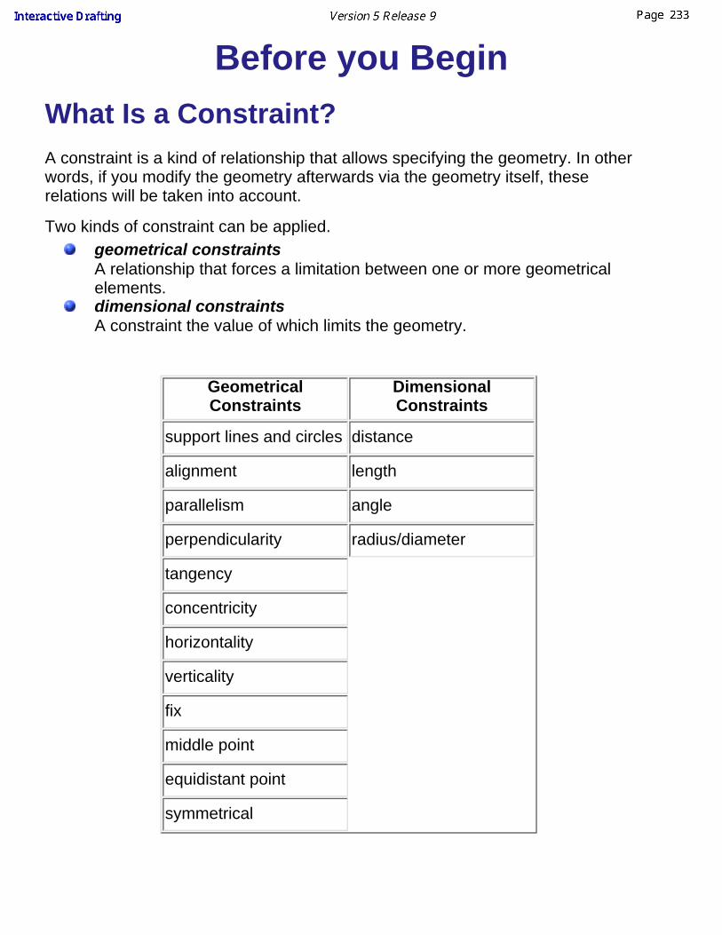
Before you Begin
What Is a Constraint?A constraint is a kind of relationship that allows specifying the geometry. In otherwords, if you modify the geometry afterwards via the geometry itself, theserelations will be taken into account.
Two kinds of constraint can be applied.geometrical constraintsA relationship that forces a limitation between one or more geometricalelements. dimensional constraintsA constraint the value of which limits the geometry.
GeometricalConstraints
DimensionalConstraints
support lines and circles distance
alignment length
parallelism angle
perpendicularity radius/diameter
tangency
concentricity
horizontality
verticality
fix
middle point
equidistant point
symmetrical
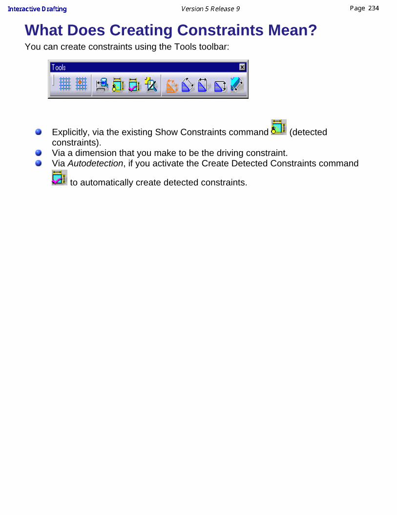
What Does Creating Constraints Mean?You can create constraints using the Tools toolbar:
Explicitly, via the existing Show Constraints command (detectedconstraints).Via a dimension that you make to be the driving constraint.Via Autodetection, if you activate the Create Detected Constraints command
to automatically create detected constraints.

Creating Geometrical ConstraintsThis task shows you how to set a relationship that forces a limitation between one or moregeometrical elements.Before creating a constraint, make sure the constraint creation option commands areactive in the Tools toolbar.
Create two lines. Make sure the Show Constraints command option is active (Toolstoolbar).
1. Select the geometrical elements to beconstrained to each others, for example twolines to be set as parallel lines.2. Click the Constraint with Dialog Box icon
from the Geometry edition toolbar.
The Constraint Definition dialog boxappears.
3. Modify the Constraint Definition dialogbox. For example, activate the Parallelismswitch.

It is impossible to create constraints between 2D and generated elements via theConstraint Definition dialog box. In the Constraint Definition dialog box, you can onlycreate constraints between similar elements. In other words, you can create constraintseither between 2D elements, or between generated elements, but not between a mix ofthese.
4. Click OK.
Both lines are now parallel to each others.
5. Modify the position of one geometrical element. For example, move one end point onone line.
The lines are driven so as to remain parallel to each others whatever the new positionand/or length you assign to one of them.
Even though you set a constraint relation between two elements, constraints are not
necessarily visualized. Check the Show Constraints command from the Tools toolbaror go to Tools->Options menu bar (Drafting/Geometry), if needed. You can also modify theconstraint color and/or width.

Creating Constraints Between 2Dand Generated Elements
This task shows you how to create associative constraints between 2D elementsand generated elements (Generative Drafting workbench).
Create an associative point between the 2D and the generated viewCreate a Constraint Between 2D and Generated Elements
Make sure the constraint creation option command is active in the Tools toolbar.
Create an associative point between the 2Dand the generated viewOpen the Constraints_2D_GeneratedElem.CATDrawing document.
1. Activate the Grid option command.
2. Click the Point icon and create a point using SmartPick.
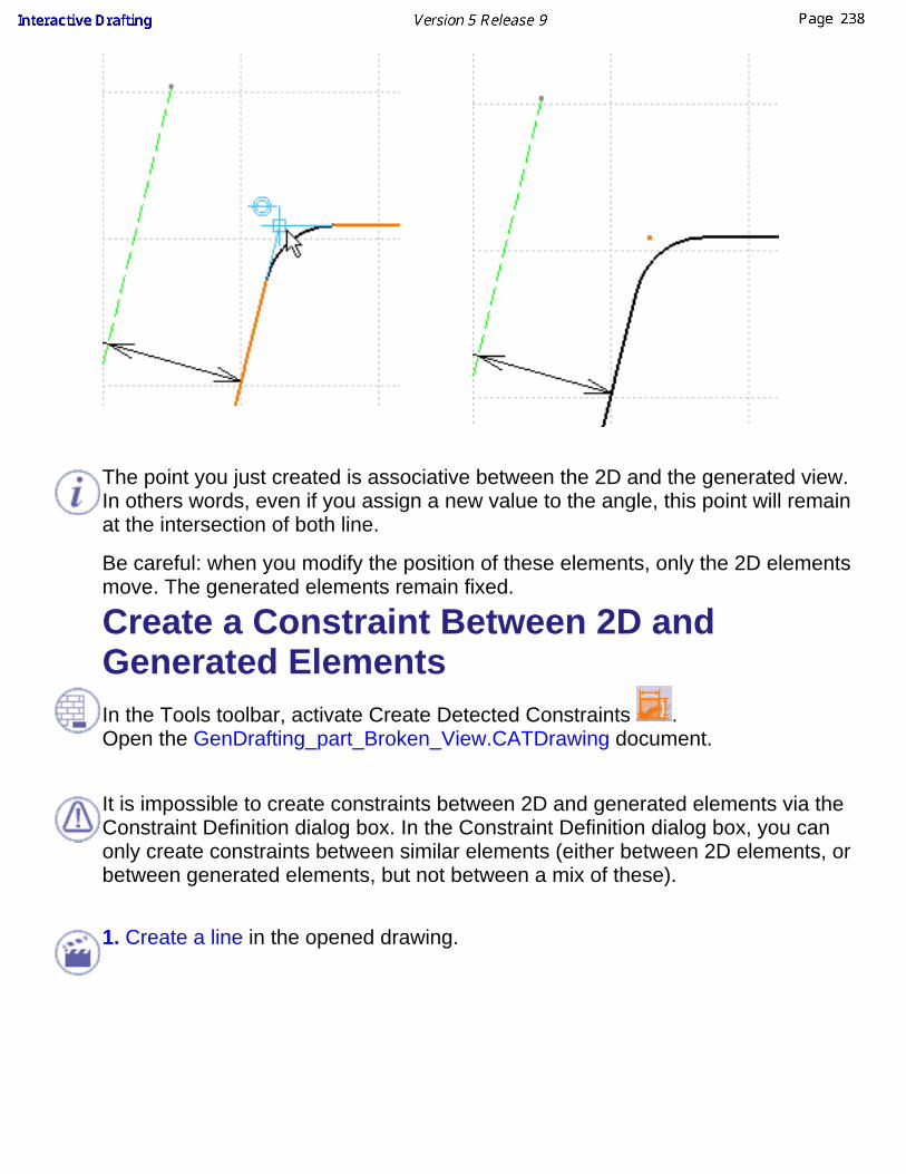
The point you just created is associative between the 2D and the generated view.In others words, even if you assign a new value to the angle, this point will remainat the intersection of both line.
Be careful: when you modify the position of these elements, only the 2D elementsmove. The generated elements remain fixed.
Create a Constraint Between 2D andGenerated ElementsIn the Tools toolbar, activate Create Detected Constraints .Open the GenDrafting_part_Broken_View.CATDrawing document.
It is impossible to create constraints between 2D and generated elements via theConstraint Definition dialog box. In the Constraint Definition dialog box, you canonly create constraints between similar elements (either between 2D elements, orbetween generated elements, but not between a mix of these).
1. Create a line in the opened drawing.

2. Click the geometrical constraints command icon and select the line
The most logical constraint is automatically offered (if you want to apply thisconstraint, click in the drawing).
Select an edge from the drawing you have opened.
The software propose you parallelism by default. If you choose this constraint,click in the drawing, otherwise...
3. ...right-click and select Perpendicularity in the contextual menu.

A constraint is created between a generated element and a sketched element.
4. You can delete this constraint: right-click on the created constraint and selectdelete in the contextual menu.

AnnotationsThe Interactive Drafting workbench lets you manipulate annotations.
In order to be consistent with the way commands have been grouped in toolbarsand subtoolbars, the following tasks are documented in chapter calledManipulating Dimensions:
Datum Feature Creation and ModificationGeometrical Tolerance Creation, Modification and Copy
Refer to T for more information about text properties.
Before You Begin
You should be familiar with basic concepts.
Create a free textCreate a text that either wraps or not, that is assigned an unlimitedwidth text frame, even though this text may reach the frame boundary.
Create associated textCreate a text which you want to be and remain associated to anexisting element.
Make an existing text associativeAt any time and once a text has been created, you can add apositional link between a text and another element.
Create a text with a leaderCreate a text with a leader either in the free space or associated withan element.
Add a leader to existing textAdd a leader to text that was previously created.
Add Frames and Sub Frames to existing textAdd a Frame or a sub Frame to text that was previously created.
Adding attribute link to textAdd one or more attribute links between text that was previouslycreated.
Replicate a text attribute:Replicate text as well as the corresponding text attribute.

Copy graphical properties:Copy the text graphical properties of one element to existing texts.
Create a datum target:Create a datum target on a view.
Modify a datum target:Modify a datum target by editing it in a dialog box.
Create a balloon:Create a balloon using a dialog box.
Creating a balloon on generated viewsCreate associative balloons on views generated from a product.
Modify a balloonModify a balloon using a dialog box.
Create a roughness symbolCreate a roughness using a dialog box.
Create a welding symbolCreate a welding symbol using a dialog box.
Create a geometry weldCreate a geometry weld symbol.
Modifying annotation positioningAssign new positioning to existing annotations.
Find/replace textLocate and then, if needed, replace string of characters.
Edit query link panelEdit feature links in a document
Insert PicturesInsert a Picture in a document.
Create a TableCreate, edit and modify a table.

Text PropertiesSetting Text Properties
This task explains how to set the properties of a text, such as font style, size, justification, etc. Text properties can be applied totext, dimension text, text with leader, balloon and datum target, as well as to text included in datum features and geometricaltolerances. You can set the properties of a text either before or after creating it.
Create a text.
1. Choose View -> Toolbars, and select Text Properties. The Text Properties toolbar is displayed.
2. Select the text.
3. Choose the properties you want to apply to this text from the Text Properties toolbar.For instance, select Italic and Bold. The properties you chose are applied to the selectedtext.
The options available in the Text properties toolbar are listed in the table below:Option Name Description
Font Name Changes the style of the text.
Font Size Changes the size of the text.
Bold Changes the weight of the text. Toggles between normal and heavy (bold).
Italic Changes the angle of the text. Toggles between normal and slanted (italic)

Underline Adds a line under the text.
Strike Thru Adds a line through the center of the text.
Overline Adds a line above the text.
Superscript Raises the text above the normal text line.
Subscript Lowers the text below the normal text line.
Left Justify Aligns multiple lines of text to the left edge of the text frame.
Center Justify Centers multiple lines of text within the text frame.
Right Justify Aligns multiple lines of text to the right edge of the text frame.
Anchor point Changes the position of the point that connects the text to the drawing or toan element. Choices are as follows:
Along the top of the text: left, center or rightAlong the vertical center of text: left, center or rightAlong the bottom of the text: left, center or right
Frame Draws a single-line frame around the text.A variety of different shapes is available.

Using Default ValuesCreate a text and set its properties as explained above.
1. Right-click the text and select Set as default to specify that you want to use the properties of this text as user defaults.
2. Choose View -> Toolbars, and select Style. The Style toolbar is displayed on the left-hand side of the screen,under the menu bar. You can toggle it.
3. From the Style toolbar, select Only User Default Properties to specify that you only want to use the properties that you set asdefaults.
The Text Properties toolbar options are then grayed out, meaning that they are no longer available. From now on, anyannotation you create will be assigned the user default properties.
To create an annotation that is not assigned the default properties, unselect Only User Default Properties. For moreinformation on using default values, see Using Default Values.You can reset the values assigned to all items to the original defaults. To do this, select Tools -> Reset All Defaults fromthe menu bar.
Specifying the Position and Orientation of a TextYou can specify the position (x, y) and/ or orientation (angle) of a text.
Create a text.
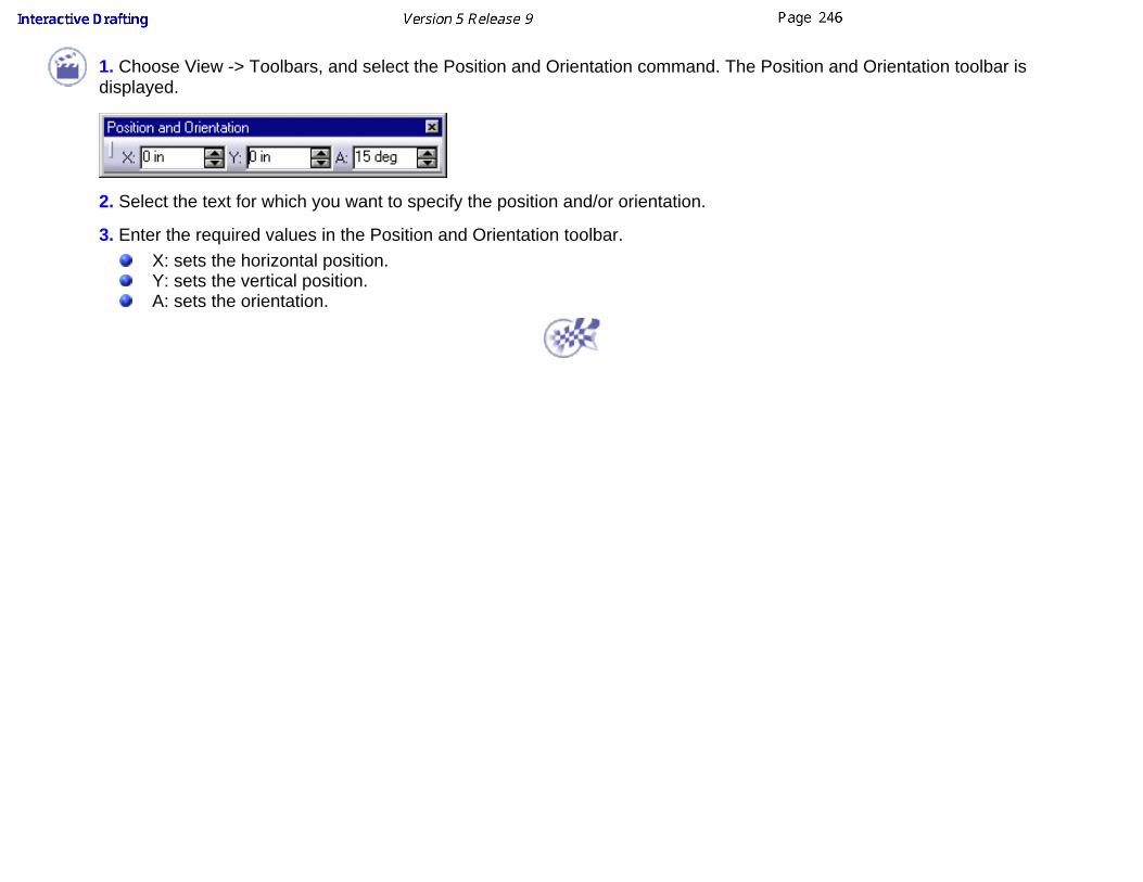
1. Choose View -> Toolbars, and select the Position and Orientation command. The Position and Orientation toolbar isdisplayed.
2. Select the text for which you want to specify the position and/or orientation.
3. Enter the required values in the Position and Orientation toolbar.X: sets the horizontal position.Y: sets the vertical position.A: sets the orientation.

Creating a Free Text This task explains how to create a text, with possible line wrapping. This text isassigned a frame of unlimited width, even though it may reach the frameboundary. You can set the properties of a text (anchor point, font size,justification, etc.) either before or after creating it.
You will learn how to perform the following operations:Creating a Free TextSpecifying Text OrientationChanging Character Ratio and SpacingMaking Text Superscript or SubscriptSpecifying the Text Display Mode
Creating a Free Text Open the Brackets_views02.CATDrawing document.
1. Click the Text icon from the Annotations toolbar.
2. Click where you want to insert the free text on the drawing. A green frameappears, as well as the Text Editor dialog box.
3. If you want to specify the horizontalboundary of the text, drag the frame to whereyou want to place the boundary. If you want thehorizontal boundary to adjust to your text,proceed with the following step.

4. Type your text in the Text Editor dialog box.
The drawing is automatically updated with the text you are typing in the TextEditor dialog box.
You can copy and paste text from another application. Its layout andproperties will not be preserved. You cannot copy complex objects (such as tables) from anotherapplication.
5. When you are done typing your text, clickOK in the Text Editor dialog box, clickanywhere on the drawing, or click anycommand. You can also click the Select icon
: in this case, the text will remain selectedso you can change its properties for example.
You can now start setting the properties of thetext you just created using the Text Propertiestoolbar.
Although you can create a text in a view that is not up-to-date, you cannotassociate it to geometry. If you try to do so, the following message will appear:

Specifying Text OrientationYou can associate the text to an element and make it parallel to it. To do this, youcan do the following:
Go to Tools -> Options-> Drafting -> Annotations tab and check Text inAnnotation Creation -> Apply snapping to. From then on, any text youcreate after having selected an element will be automatically associated tothis element.
ORWhen the above option is not activated, you can specify when you want to
associate a text to an element. To do so, click the Text icon and thenpress the shift key while selecting the element you want the text to beassociated to. You can then type your text.
You can also make the text vertical. To do this, click the Text icon and then pressthe ctrl key while clicking in the drawing where you want to create your free text.
Changing Character Ratio and Spacing In this task, you will learn how to change the character ratio and spacing of aportion of text, but it is also possible to change these for a whole text.
Create a free text as explained above.
1. Double-click the text to switch it to edit mode.
2. Select a portion of textand right-click it.
3. Click Properties in the menu that appears. The Properties dialog box appears.

4. Click the Font tab.
5. In the Character area, increase or decrease the value in the Ratio field tochange the character ratio.
5. Modify the value in the Spacing field to change the character spacing.
6. Click OK to validateyour changes. The text isupdated.
Making Text Superscript or Subscript In this task, you will learn how to make a text superscript, how to make a textsubscript, and how to specify their position.
Create a free text as explained above.
1. Double-click the text to switch it to edit mode.
2. Type a text, "subscript" for example, after the text you created previously.

3. Select the piece of textyou just typed andright-click it.
4. Click Properties in the menu that appears. The Properties dialog box appears. 5. Click the Font tab.
6. In the Attributes area, select the Subscript check box.
7. Click OK to validate your changes. The selected text is made subscript.
8. Now type another text, "superscript" for example, after the existing text. For themoment, the new text takes on the properties of the subscript text in front of it.
9. Select the piece of textyou just typed andright-click it.
10 Repeat steps 4 and 5.
11. In the Attributes area,select the Superscriptcheck box (instead ofSuperscript) and click OK.The selected text is madesuperscript.
12. For the purpose of this exercise, you will now align the subscript andsuperscript texts and set their offset and size. To do this, select the whole textand right-click it.

The offset defines the vertical position of the superscript or subscript text from thebaseline of the text. The size defines the height of the superscript or subscripttext. Both values are expressed as a percentage of the font size.
13. Click Properties in the menu that appears.
14. In the Properties dialog box, click the Text tab.
15. In the Options area, select the Back Field check box to align the texts.
16. Increase or decrease the values for the superscript and subscript texts in theOffset and Size fields to set the offset and size.
17. Click OK to validate. The subscript and superscript texts are now aligned andset as defined.
This functionality does not always work when the text is wrapped.
Specifying the Text Display ModeIn this task, you will learn how to specify the display mode for the text. For thepurpose of this exercise, you will use a text with a leader and a frame, but thisfeature is also available with text only.Create a text with a leaderand a frame.
1. Select the text and right-click it.
2. Click Properties in the menu that appears. The Properties dialog box appears.3. Click the Text tab.

4. In the Options area,choose the display modeyou want for your text fromthe Display list.
You have the followingoptions:
Show Value: displays the text, and (when applicable) its leader and itsframe. This option is selected by default.
Show Box: replaces the text and (when applicable) its frame by arectangular box and displays its leader.
Hide Value: hides the text and (when applicable) its frame but (whenapplicable) displays its leader.
5. Click OK to validate. The text is now displayed using the mode you set.
If you select Hide Value as the display mode for a text with no leader, the text willnot be visible at all on your drawing. You can find all hidden texts in a drawingusing advanced Search options. To do this, choose Edit -> Search, click theAdvanced tab. Select Drafting from the Workbench list, Text from the Type list,Display from the Attributes list. In the dialog box that appears, select = and HideValue and then click OK. Click the Search button. All hidden texts are listed.

Creating an Associated TextThis task shows you how to create a text which you want to be associated to an existing element.This text will remain associated with this element. You can set text properties either before or afteryou create the text.
Open the Brackets_views03.CATDrawing document. Create two diameter dimensions, for example.
1. Click the Text icon from the Annotationstoolbar.
2. Select the element to which you want toassociate a text. Here, we will use a dimension.
The green text frame is displayed as well as theText Editor dialog box.
3. Enter the text to be created in the Text Editordialog box or directly on the drawing. Forexample, enter diameter.
4. Click in the free space or click the Select
icon to end the text creation.
5. If needed, select the dimension and move it to the desired location.
The text remains associated to the dimension.

Note that the text is associative to the wholeselected element. In other words and in thecase of a dimension, if you move the dimensiontext exclusively, the associated text will notmove accordingly.
The table below lists the elements that can be assigned text:
Elements That Can Be AssignedText
Annotationstextdatum featuredatum targetballoonGD&Troughness symbolsweld symbolsDimensions2D elementspointscirclesellipseparabolahyperbolaGenerative Edges

Making an Existing AnnotationAssociative
This task explains how, at any time and once an annotation has been created,you can add a link between an annotation and another element. You can set textproperties either before or after you create the text.
Positional linkAvailable for every annotation.
Open the Brackets_views03.CATDrawing document. Create a text.
1. Click the Select icon .
2. Select any part of the text (text itself, frame or leader).
3. Right click and select Positional Link->Create from the contextual menu.
4. Select the element to which you want the text to be linked.
5. Select the associated element and drag it in the drawing, the text follows theelement.6. Delete existing associativity using the same dialog but selecting the Deleteoption (Positional Link contextual menu).
Orientation linkAvailable for text, text with leader, and roughness symbol.

7. Right click on the text and select Orientation Link->Create from the contextualmenu.
8. Select the element to which you want the text to be linked.9. Select the linked element and modify its orientation, the text orientation issimultaneously modified.
Elements That Are TextAssociative
Annotationstextdatum featuredatum targetballoonGD&Troughness symbolsweld symbolsDimensions2D elementspointscirclesellipseparabolahyperbolaGenerative Edges

Creating a Text With a LeaderThis task shows you how to create a text with a leader either in the free space or associated with anelement. You can set text properties either before or after you create the text.
Creating a Text with a LeaderCreating a Text with a LeaderLeader orientationText orientation
Adding a Leader to Existing TextEditing Annotation Leaders
Creating a Text With a LeaderCreate a rectangle.
Note that leader lines are displayed in either of the following ways based on the standard currently setdefining the sheet.
1. Click the Text With Leader icon from the Annotations toolbar (Texts subtoolbar).
2. Click the point on the element you want the leader to begin (arrow end).
A red frame appears.
3. Click in the free space to define a location for the text.
Both the red frame and the arrow end of the leader are now assigned white and yellow manipulators.
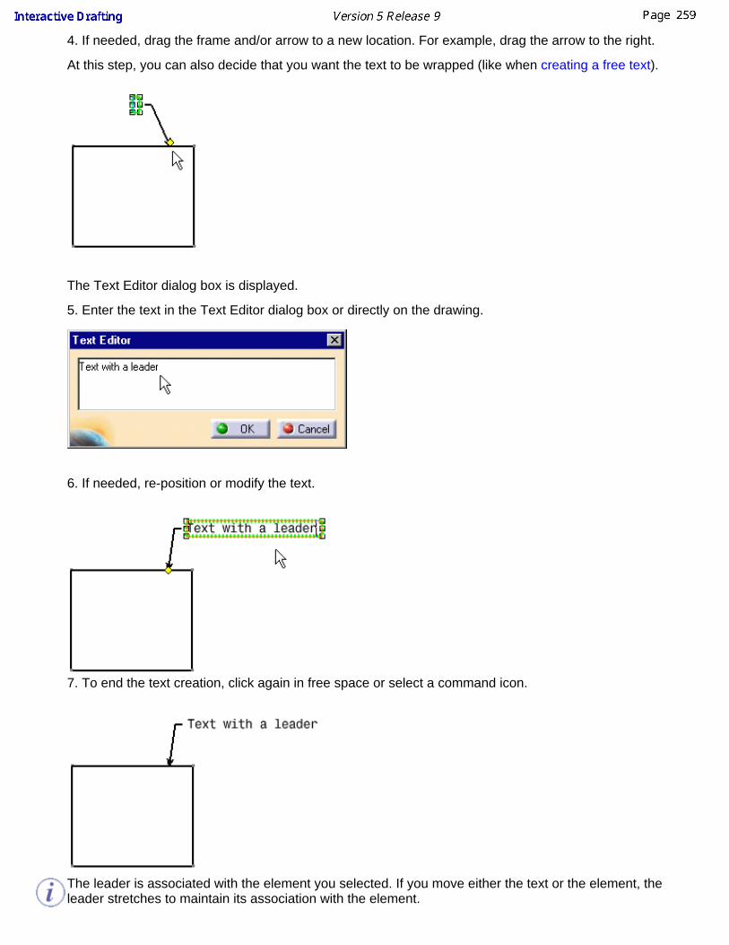
4. If needed, drag the frame and/or arrow to a new location. For example, drag the arrow to the right.
At this step, you can also decide that you want the text to be wrapped (like when creating a free text).
The Text Editor dialog box is displayed.
5. Enter the text in the Text Editor dialog box or directly on the drawing.
6. If needed, re-position or modify the text.
7. To end the text creation, click again in free space or select a command icon.
The leader is associated with the element you selected. If you move either the text or the element, theleader stretches to maintain its association with the element.

If you change the element that is associated with the leader, between both the new element and the textwith leader remains associative to each others.
8. Create a circle.
9. Move the text with a leader.
You can create a text in a view not up to date, but you can not associate it to geometry or the followingpanel appears:
Leader orientationThe leader first segment can be perpendicular to the element associated with the leader. For this, you can:
go to tools -> options-> drafting -> annotations tab and check Text with leader in AnnotationCreation -> Apply snapping to or if this option is not activated hold shift key before clicking in the drawing to position the text(previous scenario, step 3).
Text orientationThe text can be vertical. For this, hold the ctrl key before clicking in the drawing to position the text(previous scenario, step 3).
Editing Annotation LeadersYou can modify annotation leader by editing the leader breakpoints and/or move these leaders.
Create a text with a leader.
1. Position the cursor on one control point of the text with leader to be modified.
2. Right click one control point on the leader and display the contextual menu.

Add a Breakpoint Remove a Breakpoint
Remove a Leader
Move the Leader with the cursor
Add a leader to break point:(right-click on the breakpoint)
Remove a Leader / an Extremity(right-click on the extremity)
You can add a leader only in the case of atext or a welding symbol

Modify Symbol Shape
Elements That Can Be AssignedText With Leader
2D elementslinespointscirclescurvesGenerative Edges

Adding a Leader to Existing TextThis task shows you how to add a leader to text that was previously created.
Create a rectangle. Create a free text. You can set text properties either beforeor after you create the text.1. Right-click the text to which you want to add a leader.2. Select the Add Leader command that appears inthe contextual menu.
3. Click where you want to begin the leader (arrow end).
The leader appears.
4. If needed, position the leader at the desired location.
To create as many leaders as required for an existing text, useTools->Customize item and create the Add Leader command in a separatetoolbar. You will then be able to double-click the Add Leader command and clickto locate the leader(s) to be created.

If several text elements are selected as you activate the Add Leader command,the selection is cleared and a message asks you to select an annotation.
If you modify the text associated with the leader, associativity between the textand the leader is kept.

Adding Frames or a Sub FramesThis function allows you to add frames and sub frames to texts and texts with leader.
Create a free text.
1. Select the text you have created and click the icon in the Text Properties Toolbar.
2. Choose a frame in the menu
3. Click on the frame to select it
4. Right-click on the text and in the contextual menu choose the add leader command and click in the free space to endthe leader creation.
Zoom to move the leader round the text.

5. Right-click on the hanged point and select a mode in the contextual menu. The anchor points available will bedependent on your choice. Set the Standard Behaviour Off.
These anchor points allow you to move a leader around the text.
Standard Behaviour is the default mode. Automatic Mode corresponds to the point 1 of Standard Behaviour.
Frames Anchors Table:
Type of frame Standard Behaviour OFF Standard Behaviour ON
Rectangle 1 2 3 o-------o-------o / \ 4 o o 5 \ / o-------o-------o
o-------o-------o / \ 1 o o 2 \ / o-------o-------o
Square
Circle 3 __o__ 2 o o 4 | | 1 o o 5 | | 8 o o 6 --o-- 7
__o__ / \ | | 1 o o 2 | | \ / --o--
ScoredCircle
SetFixedSupport
Sym Part
Sym Set
Diamond
3 o / \ 2 o o 4 / \ 1 o o 5 \ / 8 o o 6 \ / o 7
o / \ o o / \ 1 o o 2 \ / o o \ / o
Nota
Triangle
3 o / \ 2 o o 4 / \ 1 o----o----o 5 6
o / \ o o / \ 1 o---------o 2
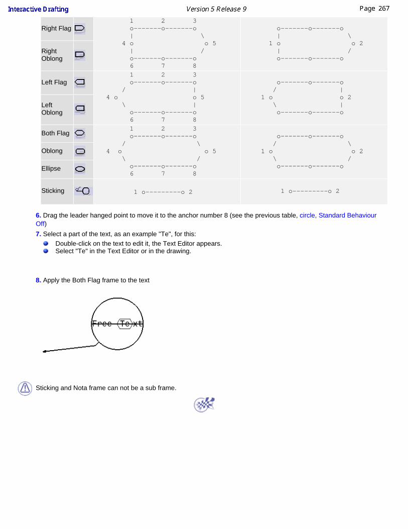
Right Flag 1 2 3 o-------o-------o | \ 4 o o 5 | / o-------o-------o 6 7 8
o-------o-------o | \ 1 o o 2 | / o-------o-------o
RightOblong
Left Flag 1 2 3 o-------o-------o / | 4 o o 5 \ | o-------o-------o 6 7 8
o-------o-------o / | 1 o o 2 \ | o-------o-------o
LeftOblong
Both Flag 1 2 3 o-------o-------o / \ 4 o o 5 \ / o-------o-------o 6 7 8
o-------o-------o / \ 1 o o 2 \ / o-------o-------o
Oblong
Ellipse
Sticking 1 o---------o 2 1 o---------o 2
6. Drag the leader hanged point to move it to the anchor number 8 (see the previous table, circle, Standard BehaviourOff) 7. Select a part of the text, as an example "Te", for this:
Double-click on the text to edit it, the Text Editor appears.Select "Te" in the Text Editor or in the drawing.
8. Apply the Both Flag frame to the text
Sticking and Nota frame can not be a sub frame.

Adding Attribute Link to TextThis task shows you how to add one or more attribute links to text.
In a first example, we will create an attribute link between a hole on the 3D part and thecorresponding text in a CATDrawing view.
In a second example, we will assign an attribute an attribute link to a view.
Open the GenDrafting_part.CATPart document and the GenDrafting_part_02.CATDrawingdocument.
1. Double-click the text to which you want to add a link.
2. Right-click on the text in the drawing and select the Attribute Link option from thecontextual menu.
3. Select the object which you want the text to be linked to, from the specification tree
(either from the 3D or from the CATDrawing document). For example, select Hole 2 from the CATPart specification tree.
The Attribute Link Panel dialog box appears:

4. Select the "Part1\PartBody\Hole.2\Diameter 8.5mm" attribute from the list displayed.
The 8.5mm attribute automatically appears both in the Text Editor dialog box and on theCATDrawing.
5. Modify the diameter of Hole 2 on the CATPart. For example, modify the hole diameterinto 13.5mm.
This modification is automatically updated on both the views generated on theCATDrawing and the linked text attribute inserted inside the text, on the condition youselect automatic update mode in the Options dialog box (Tools->Options->MechanicalDesign-> Part Design options, General tab).

At this step, you can perform a query on the link (s) you just created. For this, click theview and select the Query Objects Links option from the contextual menu.
The Query Link Panel appears which displays a list with the existing links.
Of course, you can only modify the text that is not text attribute type. To modify the textattribute, you need to isolate this text.For this:
6. Right-click the text attribute.
7. Select the Isolate Text option from the contextual menu.
Open the GenDrafting_part_02.CATDrawing document.
Create the formula:
1. Click the Formula icon from the Standard toolbar.
The Formulas: Drawing dialog box appears:

2. Create a parameter called NameOfUser.
Define the Text Attribute:
3. Click the Text icon from the Annotations toolbar and click in the free space.
4. Right-click the empty text and select the Attribute Link option from the contextual menu.
5. Select the object which you want the text to be linked to, from the specification tree. Forexample, select the CATDrawing document (very top of the specification tree).
Modify the Text Attribute:

The attribute appears on the drawing:
6. Modify the parameter by clicking the Formula icon from the Standard toolbar,double-clicking the parameter and editing it.
7. Enter the new value for the username attribute. For example, NewNameOfUser.
8. Click OK.

The linked attribute now appears. In other words, it is automatically updated.
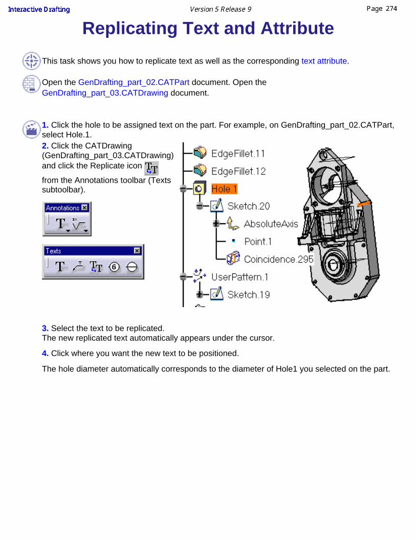
Replicating Text and AttributeThis task shows you how to replicate text as well as the corresponding text attribute.
Open the GenDrafting_part_02.CATPart document. Open theGenDrafting_part_03.CATDrawing document.
1. Click the hole to be assigned text on the part. For example, on GenDrafting_part_02.CATPart,select Hole.1.
2. Click the CATDrawing(GenDrafting_part_03.CATDrawing)and click the Replicate icon
from the Annotations toolbar (Textssubtoolbar).
3. Select the text to be replicated.
The new replicated text automatically appears under the cursor.
4. Click where you want the new text to be positioned.
The hole diameter automatically corresponds to the diameter of Hole1 you selected on the part.

5. If needed, add a text leader to the new text.

Copying Existing GraphicalProperties
This task shows you how to copy the text graphical properties of one element toexisting texts. This is true for any type of Interactive Drafting element. In this task,we will take free text as an example.
Create free texts.
1. Multi-select the free texts to be modified graphically speaking.
2. Click the Copy Object Format icon from the Graphic Properties toolbar.
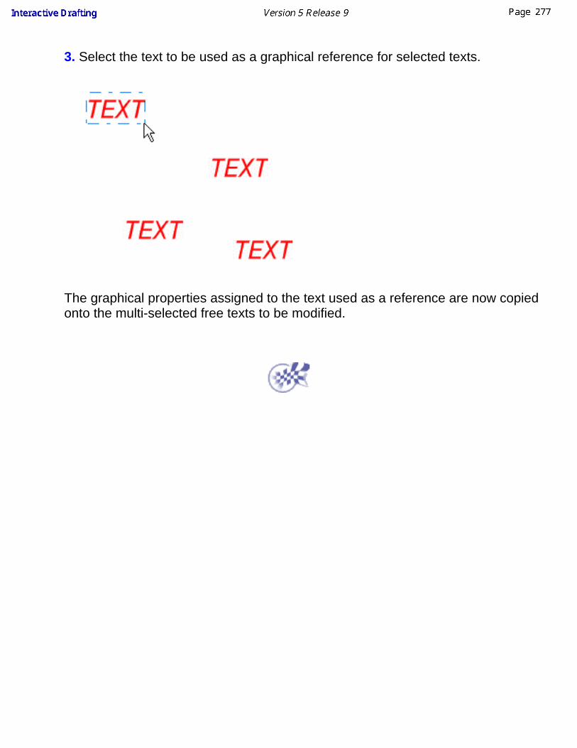
3. Select the text to be used as a graphical reference for selected texts.
The graphical properties assigned to the text used as a reference are now copiedonto the multi-selected free texts to be modified.

Creating a Datum TargetThis task will show you how to create a datum target on a right projection view.You can set text properties either before or after you create the datum target.
Open the Brackets_views03.CATDrawing document.
1. Click the Datum Target icon
from the Annotationstoolbar (Texts subtoolbar).
2. Select the attachment pointof the datum target leader.
3. Select a point to be used toposition the datum target(anchor point).
The Datum Target Creation dialog box is displayed.
4. Enter the required field. For example, 1 and A.
click this button to definethat the datum target informs

on the diameter of the selectedelement.5. Click OK.
The datum target is created.
The character string that is edited in the Datum Target Creation dialog box issimultaneously previewed on the drawing.
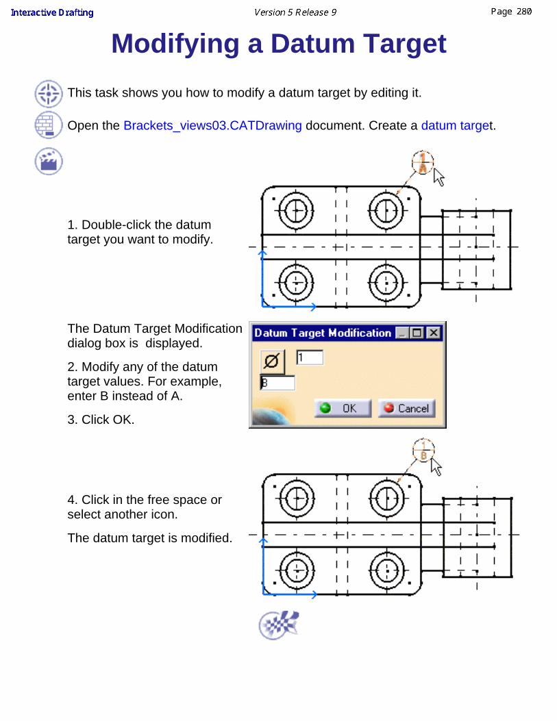
Modifying a Datum TargetThis task shows you how to modify a datum target by editing it.
Open the Brackets_views03.CATDrawing document. Create a datum target.
1. Double-click the datumtarget you want to modify.
The Datum Target Modificationdialog box is displayed.
2. Modify any of the datumtarget values. For example,enter B instead of A.
3. Click OK.
4. Click in the free space orselect another icon.
The datum target is modified.

Creating a BalloonThis task will show you how to create a balloon. You can set text properties eitherbefore or after you create the text.
Open the Brackets_views03.CATDrawing document.
1. Click the Balloon icon from the Annotations toolbar(Texts subtoolbar).
2. Select an element. Forexample, select the bottom lineof the rectangle.
3. Click to define the balloonanchor point.
The Balloon Creation dialog box appears.
4. Enter the desired characterstring. For example, enter 1.
5. Click OK.
The character string that is edited in the Balloon Creation dialog box issimultaneously previewed on the drawing.

When you create more than one balloon, the character string of this balloon isautomatically incremented.

Modifying a BalloonThis task shows you how to modify a balloon.
Open the Brackets_views03.CATDrawing document. Create a balloon.
1. Double-click the balloonyou want to modify.
The Balloon Modificationdialog box displays.
2. Modify the balloon value.
3. Click OK.
4. Click in the free space orselect another icon.
You can also modify theanchor point and thereby theposition of the balloon.

Creating Associative Balloons onViews From Products
This task will show you how to create associative balloons on views generatedfrom a product.Open theProduct_Balloon.CATProductdocument.
On this catproduct, Product Structuresubproducts have already beenassigned numbers (GenerateNumbering icon).
For more details, see ProductStructure user's guide.
1. Go to Generative Drafting workbench by openingProduct_Balloon.CATDrawing document.
2. Click the Balloon icon fromthe Annotations toolbar (Textssubtoolbar).
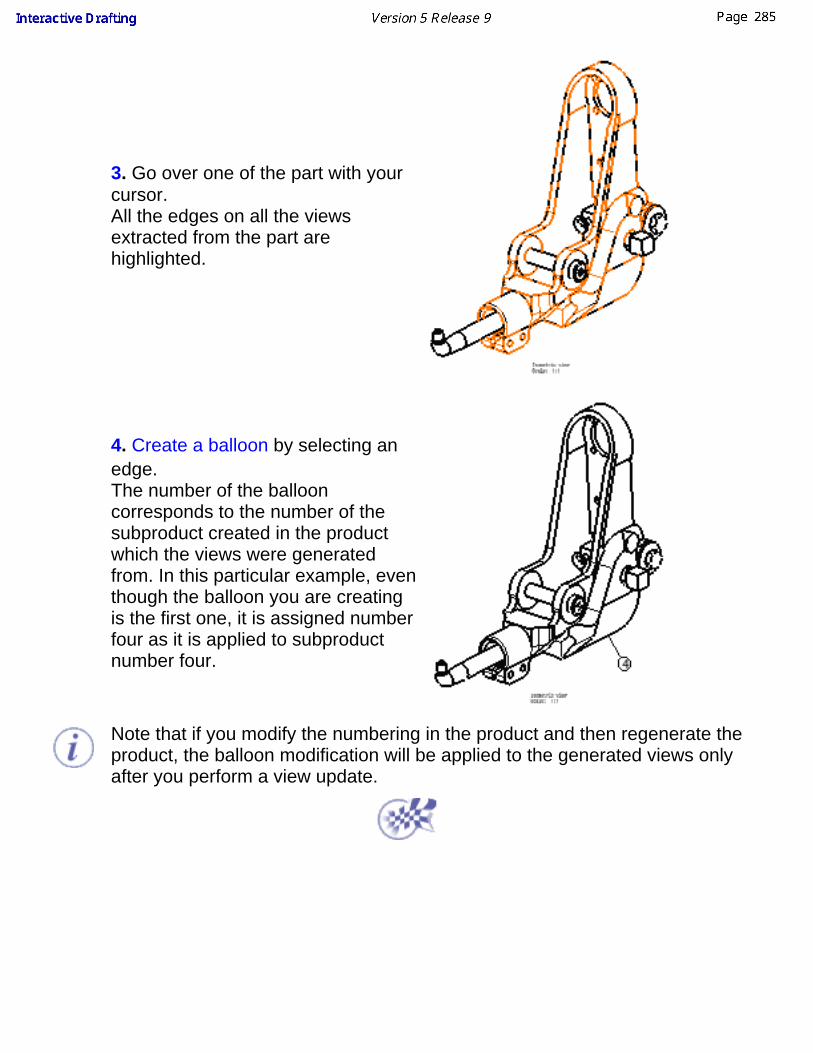
3. Go over one of the part with yourcursor.All the edges on all the viewsextracted from the part arehighlighted.
4. Create a balloon by selecting anedge.The number of the ballooncorresponds to the number of thesubproduct created in the productwhich the views were generatedfrom. In this particular example, eventhough the balloon you are creatingis the first one, it is assigned numberfour as it is applied to subproductnumber four.
Note that if you modify the numbering in the product and then regenerate theproduct, the balloon modification will be applied to the generated views onlyafter you perform a view update.
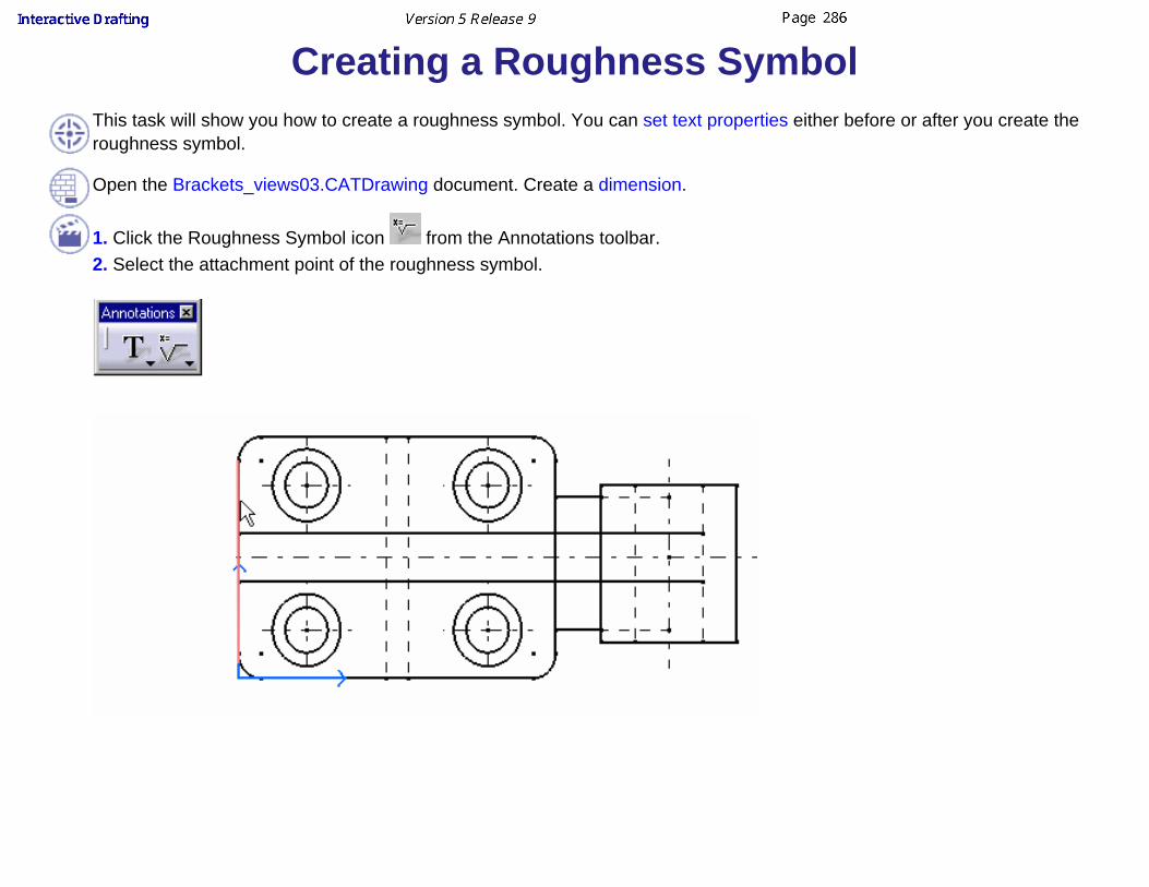
Creating a Roughness SymbolThis task will show you how to create a roughness symbol. You can set text properties either before or after you create theroughness symbol.
Open the Brackets_views03.CATDrawing document. Create a dimension.
1. Click the Roughness Symbol icon from the Annotations toolbar.2. Select the attachment point of the roughness symbol.

The Roughness Symbol Editor dialog box is displayed.
3. Enter values in the desired field(s). For example, Ra=1.6.
4. Click OK.
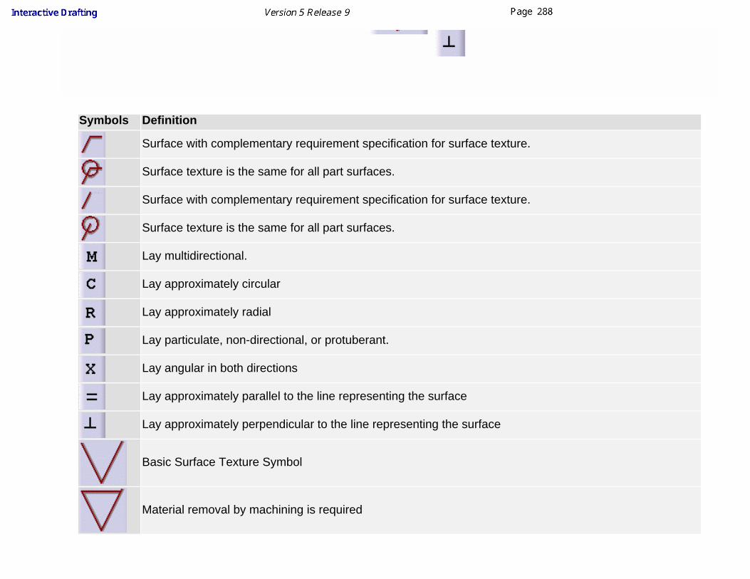
Symbols Definition
Surface with complementary requirement specification for surface texture.
Surface texture is the same for all part surfaces.
Surface with complementary requirement specification for surface texture.
Surface texture is the same for all part surfaces.
Lay multidirectional.
Lay approximately circular
Lay approximately radial
Lay particulate, non-directional, or protuberant.
Lay angular in both directions
Lay approximately parallel to the line representing the surface
Lay approximately perpendicular to the line representing the surface
Basic Surface Texture Symbol
Material removal by machining is required

Material Removal Prohibited.
5. If needed, modify the roughness symbol position by dragging it to the required location.
6. Click in the free space to validate the roughness symbol creation.
The roughness symbol is created.
At any time, you can modify the roughness symbol. For this, double-click the roughness symbol to be modified andenter the desired modifications in the displayed Roughness Symbol Editor dialog box (except orientation modificationusing the Invert switch button).You can link roughness symbol position and orientation to another element, see Making an Existing AnnotationAssociative.

Creating a Welding SymbolThis task will show you how to create a welding symbol. You can set textproperties either before or after you create the text.Welding symbols
Square butt weld
Singe V butt weld
Single bevel butt weld
Flare V butt weld
Flare bevel butt weld
Single U butt weld
Single J butt weld
Fillet weld
Spot weld
Back weld
Steep-flanked single-bevel butt weld
Steep-flanked single-V weld
Plug weld
Removable backing strip used
Permanent backing strip used
Surfacing weld

Complementary symbols
Weld with flat face
Weld with convex face
Weld with concave face
Flush finished weld
Fillet weld with smooth blended face
Complementary indications
Field weld
Weld-all-around
Weld text side (up or down)
Indent line side (up or down)
Weld tail
Reference
Open the Brackets_views03.CATDrawing document.
1. Click the Welding Symbol
icon from the Annotationstoolbar (Symbols subtoolbar).

2. Select the anchor point ofthe welding symbol.
3. Select the attachment pointof the welding symbol.
The Welding creation dialog box is displayed.
4. Enter values in the desired field(s).
5. Click OK.
6. If needed, modify the welding symbol position by dragging it to the requiredlocation.
7. Click in the free space to validate the welding symbol creation.
The welding symbol iscreated.

8. Double-click on the welding symbol to edit it and add text in the tail field.
You can close the tail using a frame.At any time, you can modify the welding symbol. To do this, double-clickthe welding symbol to be modified and enter the modifications in thedisplayed dialog box.You can import a plain text file (.txt) to use as a reference (specification,process or other) by clicking the Import File button.
The last created symbol is stored.
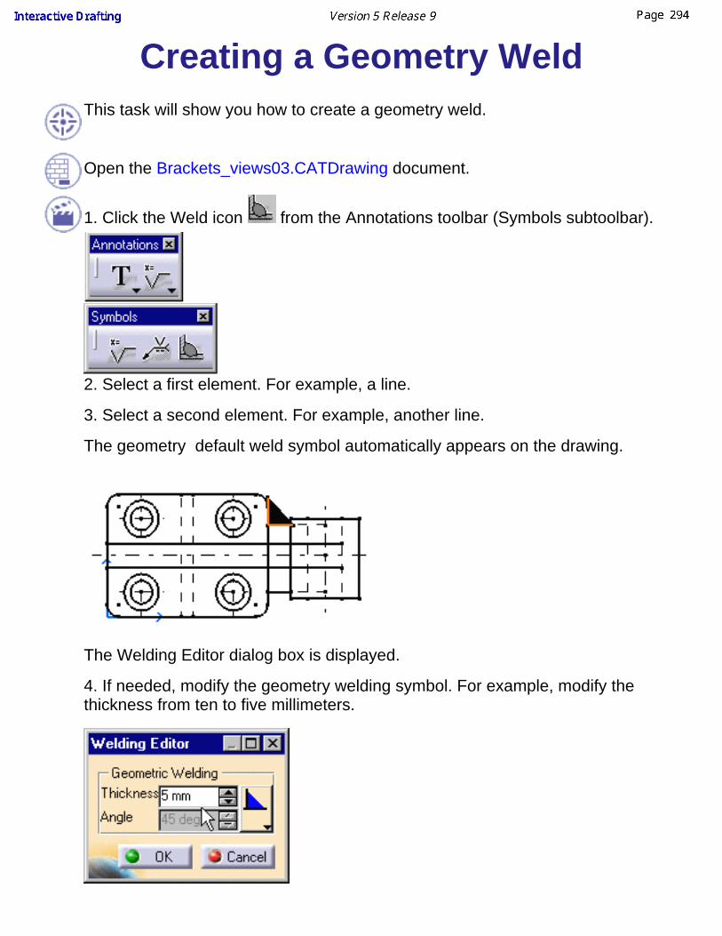
Creating a Geometry WeldThis task will show you how to create a geometry weld.
Open the Brackets_views03.CATDrawing document.
1. Click the Weld icon from the Annotations toolbar (Symbols subtoolbar).
2. Select a first element. For example, a line.
3. Select a second element. For example, another line.
The geometry default weld symbol automatically appears on the drawing.
The Welding Editor dialog box is displayed.
4. If needed, modify the geometry welding symbol. For example, modify thethickness from ten to five millimeters.

5. If needed, modify the type of the geometry welding symbol by selecting the
Change Type option from the Welding Editor dialog box.
6. Click OK.
The geometry welding symbol is created.
Care that a geometry weld correspond to an area fill that as such cannot bemodified.
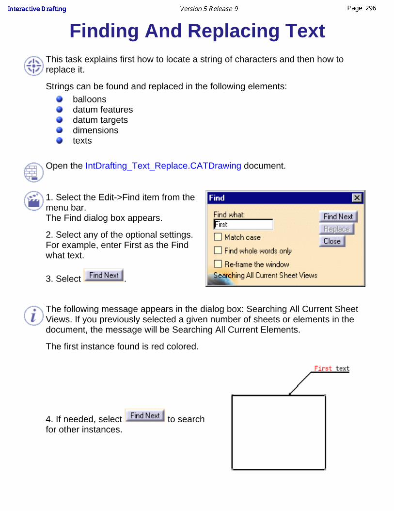
Finding And Replacing TextThis task explains first how to locate a string of characters and then how toreplace it.
Strings can be found and replaced in the following elements:balloonsdatum featuresdatum targetsdimensionstexts
Open the IntDrafting_Text_Replace.CATDrawing document.
1. Select the Edit->Find item from themenu bar.The Find dialog box appears.
2. Select any of the optional settings.For example, enter First as the Findwhat text.
3. Select .
The following message appears in the dialog box: Searching All Current SheetViews. If you previously selected a given number of sheets or elements in thedocument, the message will be Searching All Current Elements.
The first instance found is red colored.
4. If needed, select to searchfor other instances.
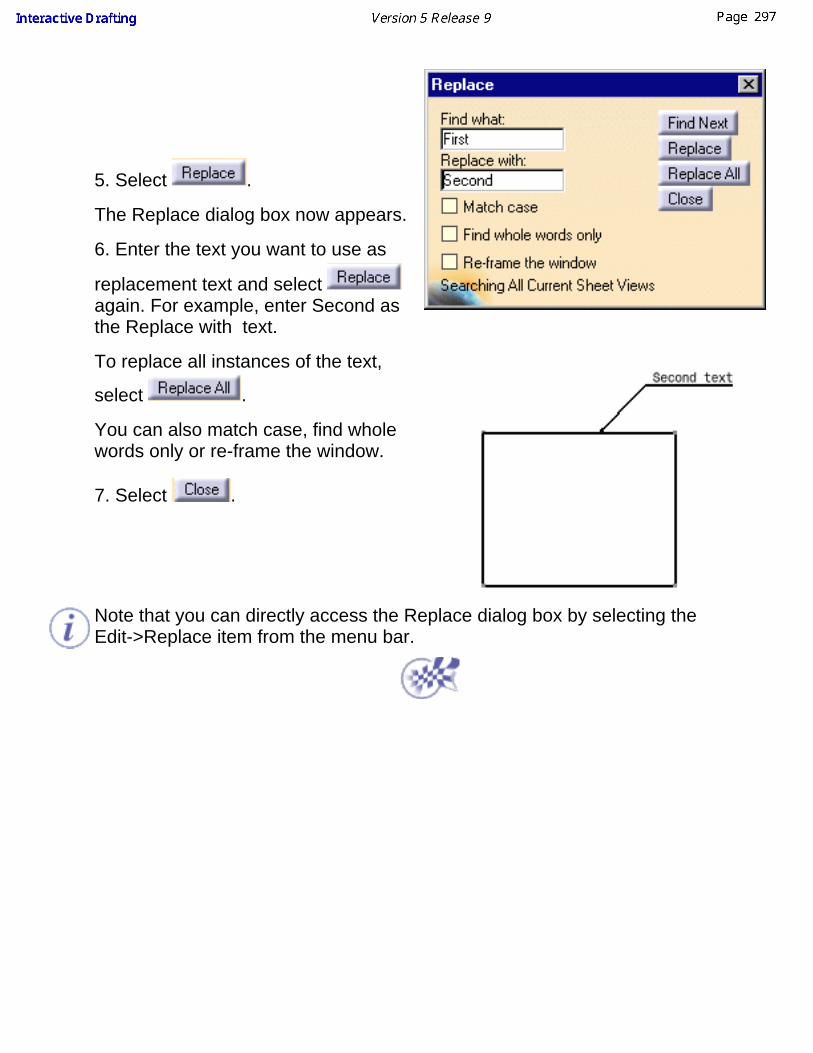
5. Select .
The Replace dialog box now appears.
6. Enter the text you want to use as
replacement text and select again. For example, enter Second asthe Replace with text.
To replace all instances of the text,
select .
You can also match case, find wholewords only or re-frame the window.
7. Select .
Note that you can directly access the Replace dialog box by selecting theEdit->Replace item from the menu bar.

Modifying Annotation PositioningThis task will show you how to assign new positioning to existing annotations.You can also modify the position of the views using the same dialog.
Open the IntDrafting_Annotations_Positioning.CATDrawing document.
1. Multi-select the annotations tobe newly positioned. In thisexample, multi-select text.
2. Select the Tools ->Positioning -> ElementPositioning command from themenu bar.
The Positioning dialog boxappears:
3. Select the Align to top option .

Align to the left
The reference text is the text, among the selected texts, that is positioned the most at the left.The text anchor point is moved to the left (for example, from the bottom center to the bottom left).The texts are aligned vertically relatively to the reference text origin point (same x abscissa as for thereference text).
Align to the center
The reference text is positioned at the middle of both left and right extremity points.The text anchor point is moved to the center (for example, from the top left to the top center).The texts are aligned vertically relatively to the reference text origin point (same x abscissa as for thereference text).
Align to the right
The reference text is the text, among the selected texts, that is positioned the most at the right.The text anchor point is moved to the right (for example, from the middle center to the middle right).The texts are aligned vertically relatively to the reference text origin point (same x abscissa as for thereference text).
Align to the top
The reference text is the text, among the selected texts, that is positioned the most at the top.The text anchor point is moved to the top (for example, from the bottom left to the top left).The texts are aligned horizontally relatively to the reference text origin point (same y coordinate as for thereference text).
Align to the middle
The reference text is positioned at the middle of both top and bottom extremity points.The selected texts are assigned the middle attribute as text origin (for example, from the top left to the middleleft).The texts are aligned horizontally relatively to the reference text origin point (same y coordinate as for thereference text).
Align to the bottom
The reference text is the text, among the selected texts, that is positioned the most at the bottom.The text anchor point is moved to the bottom (for example, from the top left to the bottom left).The texts are aligned horizontally relatively to the reference text origin point (same y coordinate as for thereference text).
4. Select the Space from left to right option and set the Space value to 30mm.

Note that when you select a Space option, the modification does not appear similarly on thedrawing. This modification only appears when you enter the new Space value in thePositioning dialog box or when you select a Space value.
5. Select the Distribute horizontally option .
6. Select the Move vertically to top option and set the Move value to -10mm.

Note that when you select a Move option, the modification does not appear similarly on thedrawing. This is only the case once you enter the new Move value in the Positioning dialogbox or when you select a spacing option.

Editing Query Link PanelThis task explains how to edit features links in a drawing and how to use the re-frame the window option.
Open the query_link.CATDrawing document.
1. Right-click on the text "Front view Scale: 1:1" and select Query Object Links in the contextual menu.
2. The Query Link Panel appears:

It displays the linked objects name and specifications.
Re-frame the window3. In the Panel, check Re-frame the window and select the linked object you want to reframe. As an example, selectViewMakeUp.3
The window is re-framed on the object.
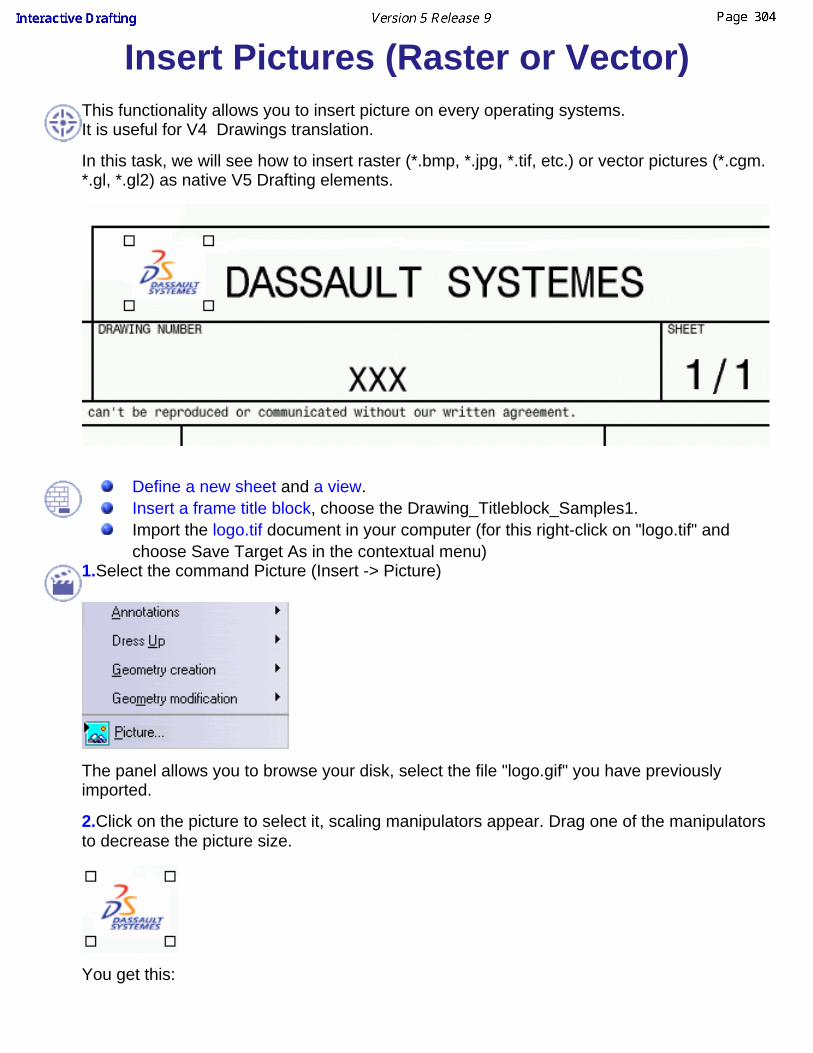
Insert Pictures (Raster or Vector)This functionality allows you to insert picture on every operating systems.It is useful for V4 Drawings translation.
In this task, we will see how to insert raster (*.bmp, *.jpg, *.tif, etc.) or vector pictures (*.cgm.*.gl, *.gl2) as native V5 Drafting elements.
Define a new sheet and a view.Insert a frame title block, choose the Drawing_Titleblock_Samples1.Import the logo.tif document in your computer (for this right-click on "logo.tif" andchoose Save Target As in the contextual menu)
1.Select the command Picture (Insert -> Picture)
The panel allows you to browse your disk, select the file "logo.gif" you have previouslyimported.
2.Click on the picture to select it, scaling manipulators appear. Drag one of the manipulatorsto decrease the picture size.
You get this:

The picture is a native V5 Drafting element, it is positioned by default at the origin of theview.The anchor point of the picture corresponds to its lower left corner.
In Properties (right-click on the picture) -> Picture tab, check the Lock aspect ratiooption to make sure picture will keep their ratio aspect.If the previous option is uncheck, use Ctrl key to keep the picture ratio aspect.Use Shift key to snap to the grid.
3. Drag it to the required position.

Creating a TableThis task shows you how to create and edit a table.
In this table, you can add text, insert columns, rows, merges cells, invert lines,invert columns, switch lines and columns, and insert views.
Choose a task:creating a table,editing and modifying a table,importing a table,inserting a view in table.
Creating a Table.Create a new sheet and a new view.
1. Click the icon to launch the command.
2. Click a point in the drawing to choose the table position.
The table can not be associative, do not select an element in the drawing tomake the table associative.3. The following panel allows you to set the number of columns and rowsexpected in the table.
Line height = string heightLine width = 5 times one string height
4. Click ok to validate the creation.

Editing and modifying a table5. Click on the table to select it and drag it to an other position.6. Double-click the table to edit it:
To select a column, click just above the column when the symbol appears.
To select a line, click on the left of the row .
7. Right-click on the table to access the general contextual menu:
Click outside of the table to leave edition.
When the table is in edition mode you can not move it anymore.
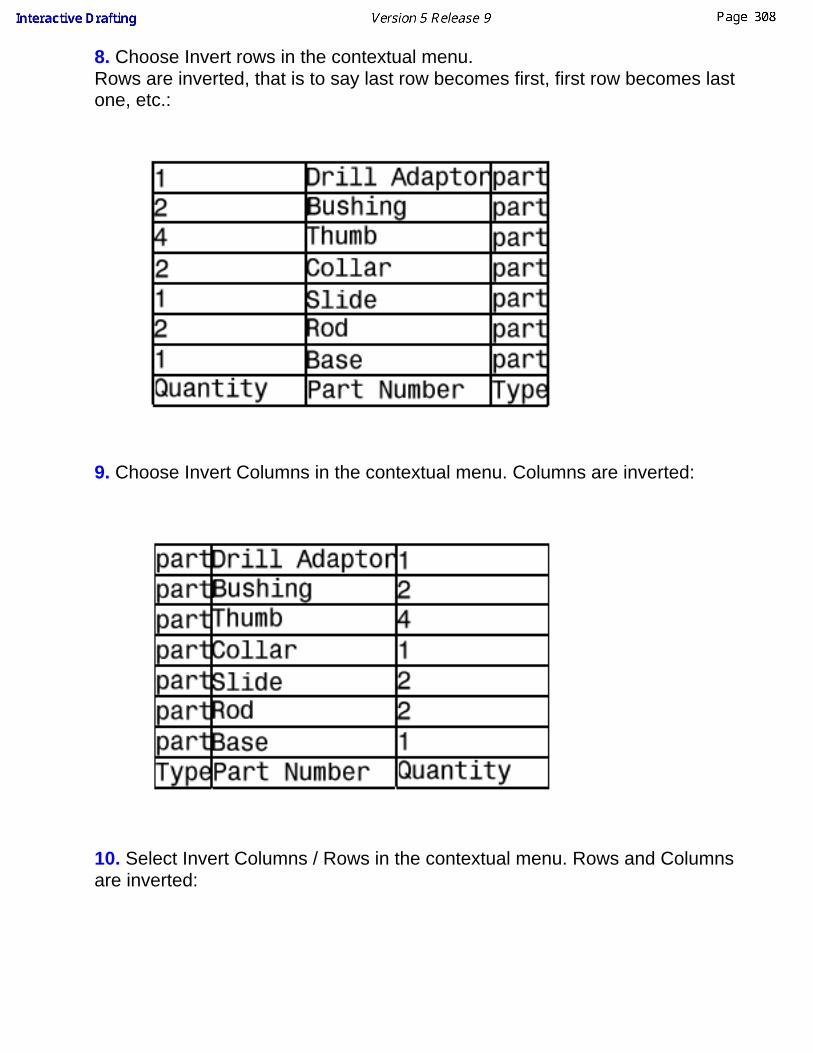
8. Choose Invert rows in the contextual menu.Rows are inverted, that is to say last row becomes first, first row becomes lastone, etc.:
9. Choose Invert Columns in the contextual menu. Columns are inverted:
10. Select Invert Columns / Rows in the contextual menu. Rows and Columnsare inverted:

11. Select a column and right-click to get the contextual menu, it allows you to:Insert a column,Delete a column,Clear the content of a column,Modify the size of a column:
you can set a new column size,or autofit the size, that is to say to define automatically the optimalsize in relation to the text.
Choose to autofit the column size, the following dialog box appears:
Set the column width to a new value value and click ok to validate.
Same functionalities are available for rows.
12. Select two cells and right-click, choose Merge in the contextual menu.
Then select the new cell formed by the two cells you have merged and chooseunmerge to split them in two cells again.
Double-click on the text of one cell. Text Editor appears, modify the text andclick ok to validate:

13. To choose vertical and horizontal text alignment, use the tool . Align the
text of a cell on the right using
Importing a tableYou can import a table (only .csv).
1. Click the Import Table icon and select the table you want to import
Inserting a view a in table

Open the GenDrafting_part.CATDrawing file. Create a table in the front views.
1. Double-click on the table to edit it and right-click in the cell you want to fill.Select Insert Object.

2. Choose the view you want to insert by clicking the view in the drawing or in thetree. Choose the Top view:
The top view is inserted in the table, and it is resized so as to fit the cell. You canresize the cell if you want to enlarge the view in the table.
You can not select the view containing the table,The view must be in the same drawing.If you modify the 3D part and update the drawing, the view in the table willbe updated as well.

Dress-Up ElementsThe Interactive Drafting workbench provides a simple method to create thefollowing view dress-up elements on existing 2D elements.
Create center lines (no reference):
Apply a center line to one or more circles.Create center lines (reference):
Apply a center line to one or more circles with respect to a reference(linear or circular).
Modify center lines:Modify one or more center lines at one or more ends of this/thesecenter lines.
Create threads (no reference):Create a thread without a reference.
Create threads (reference):Create a thread with a reference, either circular (circle or point) orlinear (line).
Create axis lines:Create an axis line by selecting lines.
Create axis lines and center lines:Create an axis line by selecting lines.
Create an area fill:Create an area fill, i.e. a closed area on which you will then applygraphical dress-up elements called patterns (these can be hatching,dotting or coloring). Patterns can be applied to area fills created fromboth sketched and generated elements.
Create arrows:Create an arrow.

Creating Center Lines (No Reference)This task will show you how to apply a pair of center lines to a circle or an ellipse.
Open the Brackets_views06.CATDrawing document.
1. Click the Center Line icon from the Dressup toolbar (Axis and Threadssubtoolbar).
2. Select a circle.
Center lines are automatically applied to the circle
.3. Click in the drawing to confirm the creation and select the center lines.4. Use manipulators to modify center lines size.
You can apply this scenario to an ellipse.

Creating Center Lines (Reference)This task will show you how to apply a pair of center lines to a circle or an ellipsewith respect to a reference (linear or circular).
Open the Brackets_views02.CATDrawing document.
1. Click the Center Line with Reference icon
from the Dressup toolbar (Axis andThreads subtoolbar).You can multi-select circles before you enter thecommand to create center lines for all selectedcircles.
2. Select the circle to be applied a pair of centerlines.
3. Select the reference line.
The center line created is associative with thereference line.
You can create a pair of center lines according to a circular reference (a point ora circle):4. Click the Center Line with Reference icon
from the Dressup toolbar (Axis andThreads subtoolbar).
You can multi-select circles before you enter thecommand and thereby apply center lines to theselected circles.

5. Select the circle to be applied a pair of centerlines.
6. Select the reference circle.
The pair of center lines created is associativewith the reference circle type element.
You can not apply this scenario to an ellipse.

Modifying Center LinesThis task will show you how to modify a pair of center lines at one or more end(s)of this/these center lines. The same method applies to axis lines.
Open the Brackets_views06.CATDrawing document.
1. Click the center line.
Red end points appear.
2. Select any end point and drag to move all the center line extremities to a newposition.

3. Press the Ctrl key while selecting any end point and drag the selectedextremity to a new position.
Multi-selection can be performed to modify center lines.
You can also modify the center line using the contextual menu (Properties) anddisplayed Properties dialog box (Graphic tab).
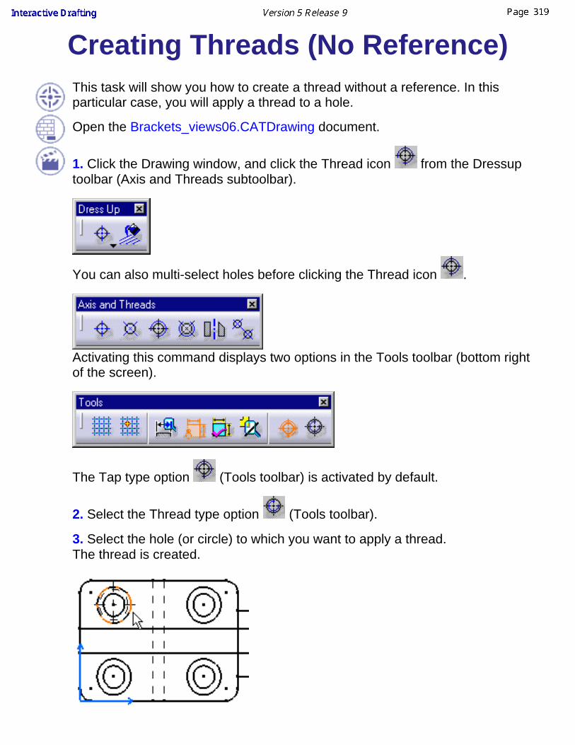
Creating Threads (No Reference)This task will show you how to create a thread without a reference. In thisparticular case, you will apply a thread to a hole.
Open the Brackets_views06.CATDrawing document.
1. Click the Drawing window, and click the Thread icon from the Dressuptoolbar (Axis and Threads subtoolbar).
You can also multi-select holes before clicking the Thread icon .
Activating this command displays two options in the Tools toolbar (bottom rightof the screen).
The Tap type option (Tools toolbar) is activated by default.
2. Select the Thread type option (Tools toolbar).
3. Select the hole (or circle) to which you want to apply a thread.The thread is created.

4. Select an axis line manipulator and drag it along a direction.
Thread axis lines are modified symmetrically.If you want to move only one axis line, hold on the Ctrl key while you aredragging the manipulator.The thread that appears on the hole is assigned a standard radius andrepresentation (compliant with the selected standard).

Creating Threads (Reference)This task shows you how to create a thread with a reference, either circular(circle or point) or linear (line). In this particular case, you will apply a thread to ahole with a line as reference.
Open the Brackets_views06.CATDrawing document.
1. Click the Drawing window, and click the
Thread with Reference icon from theDressup toolbar (Axis and Threadssubtoolbar).
You can multi-select holes before you enter thecommand and then apply center lines to theselected holes.
Activating this command displays two optionsin the Tools toolbar.
The Reference Tap type option (Tools toolbar) is activated by default.
2. Select the Reference Thread type option (Tools toolbar).
3. Select a reference line.The thread is created according to thisreference.
4. Select a manipulator and drag it along a direction.
Thread axis lines are modified symmetrically.If you want to move only one axis line, hold on the Ctrl key while you aredragging the manipulator.
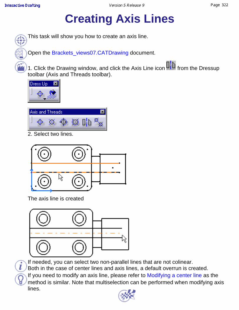
Creating Axis LinesThis task will show you how to create an axis line.
Open the Brackets_views07.CATDrawing document.
1. Click the Drawing window, and click the Axis Line icon from the Dressuptoolbar (Axis and Threads toolbar).
2. Select two lines.
The axis line is created
If needed, you can select two non-parallel lines that are not colinear.Both in the case of center lines and axis lines, a default overrun is created.If you need to modify an axis line, please refer to Modifying a center line as themethod is similar. Note that multiselection can be performed when modifying axislines.
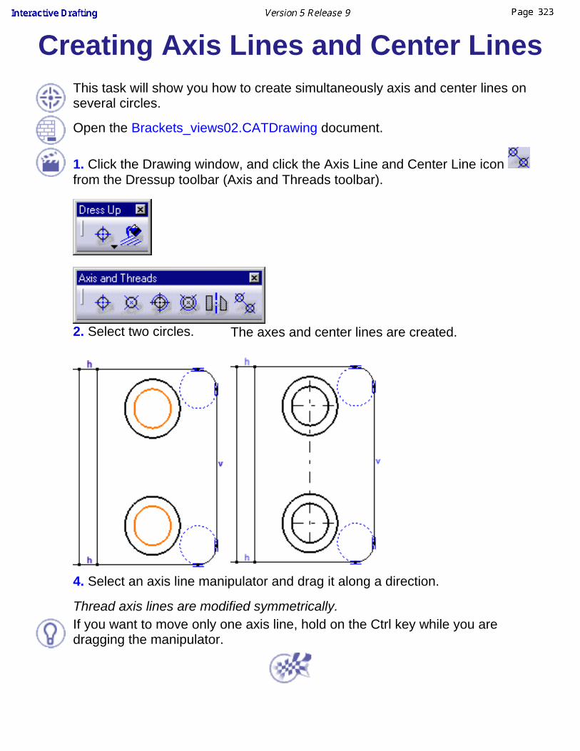
Creating Axis Lines and Center LinesThis task will show you how to create simultaneously axis and center lines onseveral circles.
Open the Brackets_views02.CATDrawing document.
1. Click the Drawing window, and click the Axis Line and Center Line icon from the Dressup toolbar (Axis and Threads toolbar).
2. Select two circles. The axes and center lines are created.
4. Select an axis line manipulator and drag it along a direction.
Thread axis lines are modified symmetrically.If you want to move only one axis line, hold on the Ctrl key while you aredragging the manipulator.
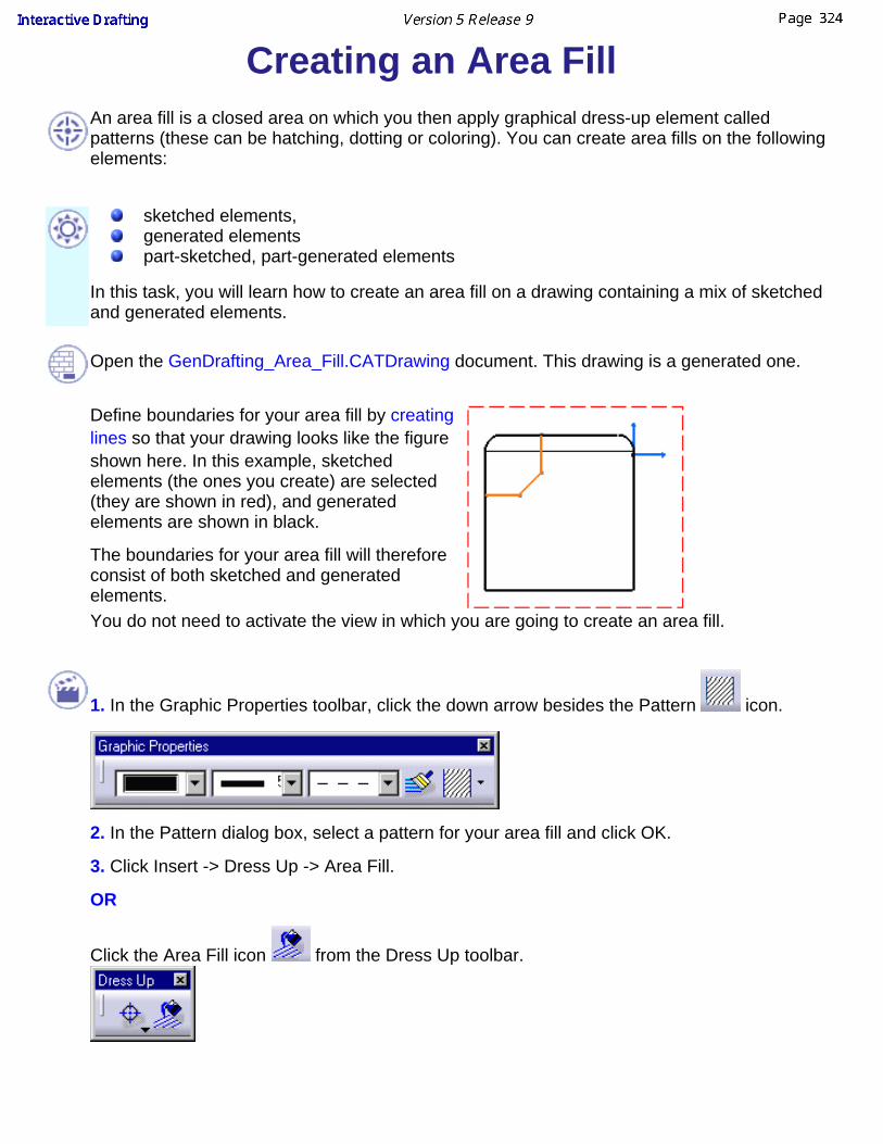
Creating an Area Fill
An area fill is a closed area on which you then apply graphical dress-up element calledpatterns (these can be hatching, dotting or coloring). You can create area fills on the followingelements:
sketched elements, generated elementspart-sketched, part-generated elements
In this task, you will learn how to create an area fill on a drawing containing a mix of sketchedand generated elements.
Open the GenDrafting_Area_Fill.CATDrawing document. This drawing is a generated one.
Define boundaries for your area fill by creatinglines so that your drawing looks like the figureshown here. In this example, sketchedelements (the ones you create) are selected(they are shown in red), and generatedelements are shown in black.
The boundaries for your area fill will thereforeconsist of both sketched and generatedelements.You do not need to activate the view in which you are going to create an area fill.
1. In the Graphic Properties toolbar, click the down arrow besides the Pattern icon.
2. In the Pattern dialog box, select a pattern for your area fill and click OK.
3. Click Insert -> Dress Up -> Area Fill.
OR
Click the Area Fill icon from the Dress Up toolbar.
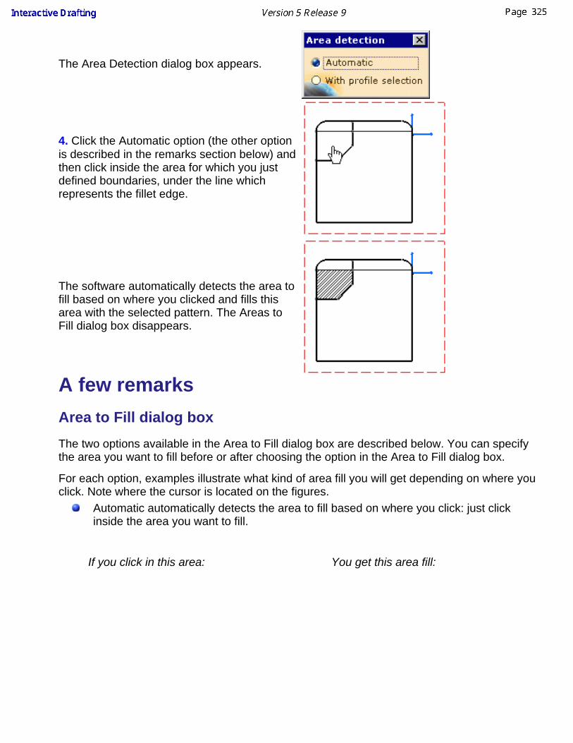
The Area Detection dialog box appears.
4. Click the Automatic option (the other optionis described in the remarks section below) andthen click inside the area for which you justdefined boundaries, under the line whichrepresents the fillet edge.
The software automatically detects the area tofill based on where you clicked and fills thisarea with the selected pattern. The Areas toFill dialog box disappears.
A few remarks
Area to Fill dialog box
The two options available in the Area to Fill dialog box are described below. You can specifythe area you want to fill before or after choosing the option in the Area to Fill dialog box.
For each option, examples illustrate what kind of area fill you will get depending on where youclick. Note where the cursor is located on the figures.
Automatic automatically detects the area to fill based on where you click: just clickinside the area you want to fill.
If you click in this area: You get this area fill:

With profile selection lets you specify the area to fill: select all the 2D elements that
make up the boundary of the area you want to fill, and then click inside this area.As you select elements on a view,intersection symbols (stars) appearwhere elements intersect. Thisenables you to know where theprofile is open: in this case,intersection symbols do not appear.As you cannot apply an area fill toan open profile, make sure allelements intersect.If you select these elements: You get this area fill:

Miscellaneous remarks about applying area fills
Whichever option you choose in the Areas to Fill dialog box, make sure the profile youselect is closed, i.e. that all elements that make up its boundary intersect. An errormessage will appear if you select a profile which is not closed.When you create an area fill on sketched elements, or on part-sketched, part-generatedelements, extra sketched elements are added over the generated elements which makeup the boundaries of the area fill. Also, coincidence constraints are created between theoriginal generated elements and the added sketched elements. On generated drawings, the area fill is not associative with the 3D part. If you modify theoriginal 3D part and then update the generated drawing, the area fill will not bechanged.Select elements carefully: the area will be filled according to the elements you selected.If you apply modifications to the filled area, the pattern will be modified accordingly.If you create text in a filled area, the background of the text will be blanked as shown
here. With hatching or dotting patterns, the spacing between each hatch or dot is sometimeslarger than the area to fill. This makes it impossible to display the pattern properly. Insuch a case, the area fill contour is made bold and is turned into the same color as thepattern color. This enables you to identify items with area fills even if the pattern is notvisible. The figures below illustrate what the sketched element will look like in such acase.

What you have before applying thepattern:
What you get if the pattern cannotbe displayed:

Creating Arrows This task will show you how to create an arrow. For the purpose of this exercise,you will use an arrow to illustrate the kind of hole you want to apply to a circle.
Open the Brackets_views06.CATDrawing document.
1. Click the Drawing window, and select Insert->Dressup->Arrow from the menubar.
2. Click a point or select an object to define the arrow starting point (the tail). Forexample, select a circle.3. Click another point or select another object to define the arrow extremity (thehead). The arrow is created.
The arrow and the selected object are associative.

To modify the position of the arrow, click the arrow and use the yellowmanipulators to drag it to its new location.
To modify the general appearance of the arrow, either click the arrow andthen use the Graphic Properties toolbar, or right-click the arrow and thenuse the Properties dialog box (select Properties and click the Graphic tab).
4. You will now add a breakpoint to the arrow. Select it and right-click on a yellowmanipulator. A contextual menu appears.

5. Select Add a Breakpoint. A breakpoint is added to the arrow; you can drag it tochange the arrow path.
6. You will now choose a symbol for the arrow tail. To do this, right-click on theyellow tail manipulator.
7 In the contextual menu, point to Symbol Shape and select a symbol, FilledCircle for example.
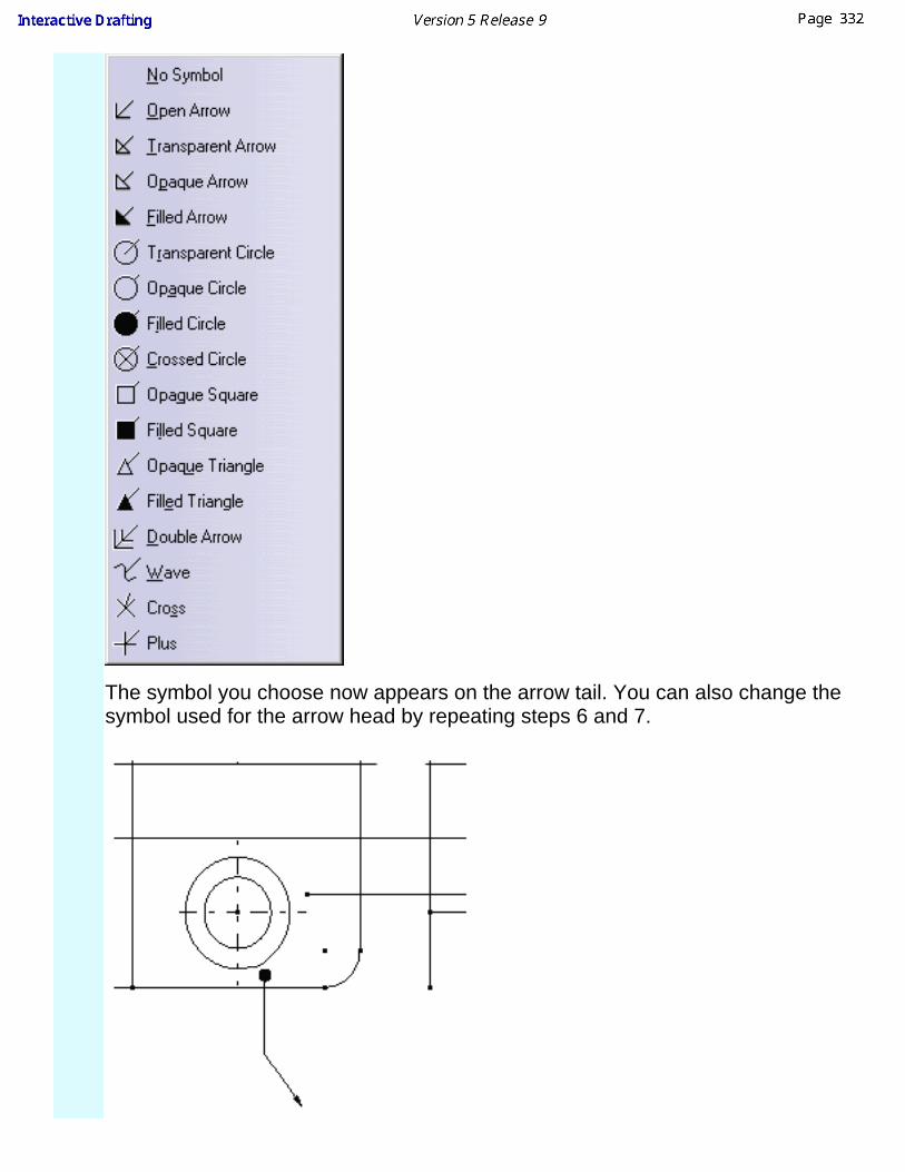
The symbol you choose now appears on the arrow tail. You can also change thesymbol used for the arrow head by repeating steps 6 and 7.

8. You will now create an interruption on the arrow tail. Right-click on the yellowtail manipulator again.
9. In the contextual menu, select Add an Interruption. An interruption is added tothe arrow.
You cannot add another extremity to an arrow.Arrow angle and length are defined by standards. For more information,see Managing Standards.
SmartPickSmartPick is an intuitive, easy-to-use tool designed to make all your 2D geometryelement creation and edition tasks as simple as possible.
SmartPick basic information is available in Sketcher user'sguide.Care that in Sketcher user's guide, we inserted images that correspond toSketcher workbench and therefore illustrate geometry in an environmentthat is different from Drafting environment (background color, for example).
SmartPick is an easy-to-use tool designed to make all your geometry creation assimple as possible.
SmartPick dynamically detects the following geometrical constraints:support lines and circlesalignmentparallelismperpendicularitytangencyconcentricityhorizontalityverticalitymiddle point
Note that when you use SmartPick, you do NOT necessarily create constraints.
Creating Constraints via SmartPick
Using SmartPick

Creating Constraints via SmartPickThis task shows you how to detect, create and visualize constraints. For example, let's create twoconstrained parrallel lines.
1. Click the Create Detected Constraints icon from the Tools toolbar.
2. Create a first line.
3. Create a second line.SmartPick can be used to create certain elements on the drawing. More precisely, only theelements which the cursor last went over will be used to apply SmartPick constraints. In otherwords, you simply need to move the cursor over the element you want to use as reference for aconstraint.No element is picked:
To detect parallelism constraints,go over the line to be used as reference.
As a result, a parallelism constraint is detectedand created.
To visualize detected and created constraints, make sure the Show Constraints command ison, or that the Tools->Options command (Drafting/Geometry) is set to the visualize option.
When a constraint is detected by smartpicking, you can temporarily deactivate this constraint bymaintaining the Shift key pressed.When a constraint is detected by smartpicking, you can temporarily lock this constraint bymaintaining the Ctrl key pressed.
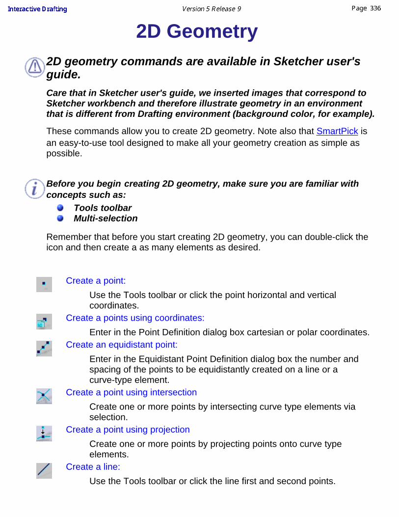
2D Geometry 2D geometry commands are available in Sketcher user'sguide.Care that in Sketcher user's guide, we inserted images that correspond toSketcher workbench and therefore illustrate geometry in an environmentthat is different from Drafting environment (background color, for example).
These commands allow you to create 2D geometry. Note also that SmartPick isan easy-to-use tool designed to make all your geometry creation as simple aspossible.
Before you begin creating 2D geometry, make sure you are familiar withconcepts such as:
Tools toolbarMulti-selection
Remember that before you start creating 2D geometry, you can double-click theicon and then create a as many elements as desired.
Create a point:Use the Tools toolbar or click the point horizontal and verticalcoordinates.
Create a points using coordinates:Enter in the Point Definition dialog box cartesian or polar coordinates.
Create an equidistant point:Enter in the Equidistant Point Definition dialog box the number andspacing of the points to be equidistantly created on a line or acurve-type element.
Create a point using intersectionCreate one or more points by intersecting curve type elements viaselection.
Create a point using projectionCreate one or more points by projecting points onto curve typeelements.
Create a line:Use the Tools toolbar or click the line first and second points.
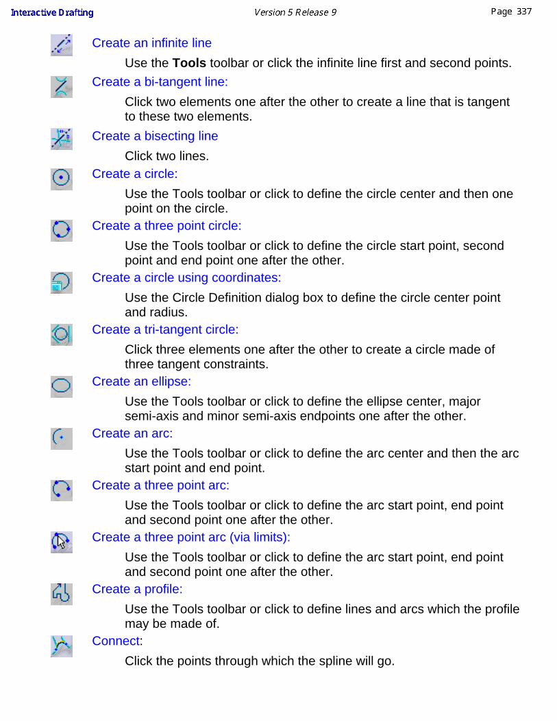
Create an infinite lineUse the Tools toolbar or click the infinite line first and second points.
Create a bi-tangent line:Click two elements one after the other to create a line that is tangentto these two elements.
Create a bisecting lineClick two lines.
Create a circle:Use the Tools toolbar or click to define the circle center and then onepoint on the circle.
Create a three point circle:Use the Tools toolbar or click to define the circle start point, secondpoint and end point one after the other.
Create a circle using coordinates:Use the Circle Definition dialog box to define the circle center pointand radius.
Create a tri-tangent circle:Click three elements one after the other to create a circle made ofthree tangent constraints.
Create an ellipse:Use the Tools toolbar or click to define the ellipse center, majorsemi-axis and minor semi-axis endpoints one after the other.
Create an arc:Use the Tools toolbar or click to define the arc center and then the arcstart point and end point.
Create a three point arc:Use the Tools toolbar or click to define the arc start point, end pointand second point one after the other.
Create a three point arc (via limits):Use the Tools toolbar or click to define the arc start point, end pointand second point one after the other.
Create a profile:Use the Tools toolbar or click to define lines and arcs which the profilemay be made of.
Connect:Click the points through which the spline will go.

Create a parabola by focus:Click the focus, apex and then the parabola two extremity points.
Create a hyperbola by focus:Click the focus, center and apex, and then the hyperbola two extremitypoints.
Create a conic:Click the desired points and excentricity for creating an ellipse, acircle, a parabola or a hyperbola, using tangents, if needed.
Create a spline:Click the points through which the spline will go.
Create a rectangle:Use the Tools toolbar or click the rectangle extremity points one afterthe other.
Create an oriented rectangle:Use the Tools toolbar or click to define a first side for the rectangleand then a point corresponding to the rectangle length.
Create a parallelogram:Use the Tools toolbar or click to define a first side for theparallelogram and then a point corresponding to the parallelogramlength.
Create an hexagon:Use the Tools toolbar or click to define the hexagon center anddimension.
Create an elongated hole:Use the Tools toolbar or click to define the center to center axis andthen a point corresponding to the curved oblong profile length andangle.
Create a cylindrical elongated hole:Use the Tools toolbar or click to define the center to center circularaxis and then a point corresponding to the curved oblong profile lengthand angle.
Create a keyhole profile:Use the Tools toolbar or click to define the center to center axis andthen both points corresponding to both radii.

2D Geometry Operations2D geometry commands are available in Sketcher user'sguide.Care that in Sketcher user's guide, we inserted images that correspond toSketcher workbench and therefore illustrate geometry in an environmentthat is different from Drafting environment (background color, for example).
These commands allow you to modify and perform various operations on 2Dgeometry.
Modify Elements Coordinates
Use the Line Definition dialog box to modify element coordinates.Create a corner:
Create a rounded corner (arc tangent to two curves) between twolines using trimming operation.
Create a chamfer:Create a chamfer between two lines using trimming operation.
Trim elements:Trim a line or a circle (either one element or all the elements).
Break elements:Break any type of curves.
Create symmetrical elements:Repeat existing elements using a line, a construction line or an axis.
Translate elements:Perform a translation on 2D elements by defining the duplicate modeand then selecting the element to be duplicated.
Rotate elements:Rotate elements by defining the duplicate mode and then selecting theelement to be duplicated.
Scale elements:Resize a profile to the dimension you specify.
Offset elements:Duplicate a line, arc or circle type element.
Copy / Paste elements:Copy and paste element.

Copying and Pasting ElementsThis task will show you how to copy and paste drafting elements.
1. Select the element you want to cut or copy.
2. To copy, you can either:
click the Copy icon select the Edit->Copy commandselect the Copy command in the contextual menu
This places what you copy in the clipboard.
3.
To paste, you can either:
click the Paste icon select the Edit->Paste commandselect the Paste command in the contextual menu
If you delete an element after copying it you will not be able to paste itanymore.

The Interactive Drafting workbench provides a simple method to print oneor more sheets inserted in your document.
See Printing documents in infrastructure documentation for classicprinting.
See Print using clipping operator, to print only a part of a drawing.

Printing a Document QuicklyThis task will show you how to quickly print a given sheet.
When printing a sheet, the current filter and layers (those used for screendisplay) are taken into account. For more details on layers and filters, seeInfrastructure User's Guide.
Open a CATDrawing document. Create a circle, a line and a profile on thisdocument.
1. Select File -> Print Preview from the menu bar.
The Print Preview dialog box is displayed.

2. Press OK.
3. Select File -> Print from the menu bar. The Print dialog box displays.
4. Click the required options from the box.
5. Press OK.
You may print either all or given sheets (the sheet selected or a given numberof existing sheets).
You may also print the views currently displayed on your screen (Currentdisplay option).
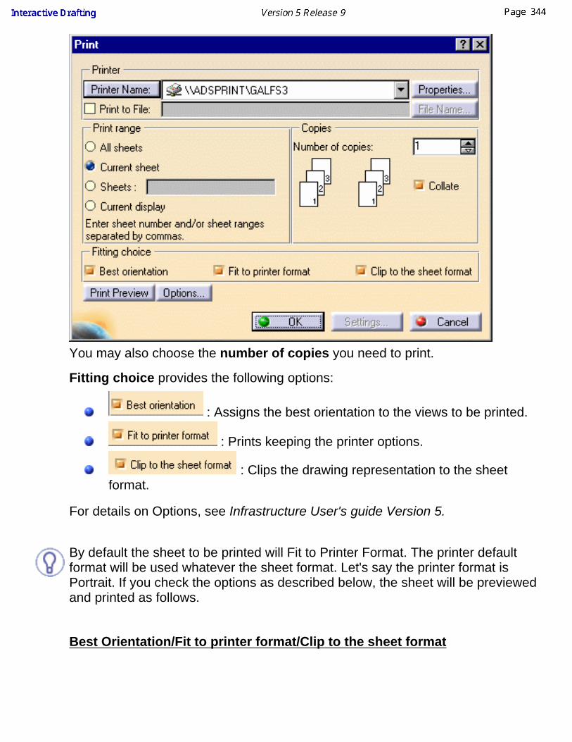
You may also choose the number of copies you need to print.
Fitting choice provides the following options:
: Assigns the best orientation to the views to be printed.
: Prints keeping the printer options.
: Clips the drawing representation to the sheetformat.
For details on Options, see Infrastructure User's guide Version 5.
By default the sheet to be printed will Fit to Printer Format. The printer defaultformat will be used whatever the sheet format. Let's say the printer format isPortrait. If you check the options as described below, the sheet will be previewedand printed as follows.
Best Orientation/Fit to printer format/Clip to the sheet format

Fit to printer format/Clip to the sheet format

Clip to the sheet format
Best orientation/Clip to the sheet format

Let's start from a new drawing:
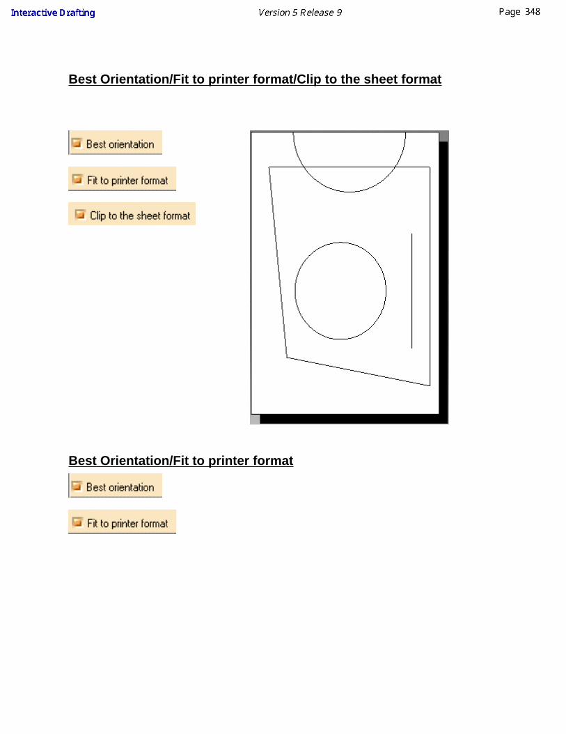
Best Orientation/Fit to printer format/Clip to the sheet format
Best Orientation/Fit to printer format


Printing a Document After ModifyingCurrent Display Settings
This task shows how to modify the settings of a document you will then print.
Create views on different sheets with the Landscape orientation.
1. Select File -> Print from the menu bar.The Print dialog box is displayed.
2. Click the required Printer options from the dialog box.
3. Activate the Current display option.
4. Click the Options option from the box.

5. If needed, select the Color tab.
6. If needed, select the Bannertab.
7. If needed, select the Varioustab.
8. Click OK.
9. Click the Settings option from the Print dialog box.
The Layout dialog box is displayed.
10. De-activate the Fit in Page option.11. For example, click the center switch for positioning the sheet at the center ofthe previewed layout.
12. Press OK.

13. Select the Print Preview optionfrom the Print dialog box.
The Print Preview dialog box isdisplayed.14. Press OK.
The Print dialog box is displayed.15. Press OK to launch theprinting operation.

Printing using clipping operatorThis task will show you how to print using a clipping operator with scaling support.
Open the Product_Balloon.CATDrawing document.
1. Select File -> Print
2. In the Print Dialog Box, choose Selection in Print Area.
It activate the select mode button and allows you to select the area to print.
3. Click on the select mode button and drag the cursor on the drawing to define the PrintArea.

4. Click ok to print the area.

Advanced TasksAdvanced tasks in the Interactive Drafting workbench deal with importing,exporting and inserting DXF/DWG files into a CATDrawing, importing andexporting CGM files. Managing standards is also part of the advanced tasks. Youcan manage the standards used for texts and annotations using the parametersincluded in the standard ASCII file.
You can perform the following advanced tasks:
Exporting a CATDrawing into a DXF/DWG FileImporting a DXF/DWG File into a CATDrawing
Inserting a DXF/DWG File into an Existing CATDrawingImporting a CGM fileExporting a CGM FileManaging Standards
Note that most advanced tasks are actually documented in the InfrastructureUser's Guide. Therefore, the tasks above (except for Managing Standards) link tothis guide.
All advanced tasks provide links to CATDrawing document samples that you canuse for practicing. When opening a CATDrawing document sample using the httpprotocol, make sure the application associated to this file type is defined on theserver. In other words, in the Internet Explorer address field you must see"http://...".

Managing Standards This section lists the parameters contained in the standard files, and provides explanations. Standard files make it possible to:
customize dimensions, annotations and dress-up elementsWhen you modify the element properties, the modifications will only be applied to the selected element. If you modify the standard file, modifications willbe applied in all the drawing.The values of the parameters in the file are taken into account when the CATDrawing document is created (File -> New). The values are copied into theCATDrawing, thus making it possible to send the CATDrawing files without needing to send the standard file along.control the user interface, with General Parameters to restrict the values of some element propertiesdefine new dimension tolerance and/or value display styles. Once defined, a style is applied to elements as a property (see the summary table ofpredefined styles).
The format of standard file has been changed compared to previous releases. If you were using a customized CATDrwStandard file on a previousrelease (up to CATIA V5R8), you need to upgrade the standard file to the new XML format.
The location of the standard files and the ability to define new standards are controlled by the administrator.
Management of Drafting StandardsA standard file is an xml file which enables to customize globally for a CATDrawing the appearance and behaviour of the drafting elements.
The standard file contains a set of parameters with their values, which are copied into each CATDrawing when it is created. Since each drawing contains acopy of the standard, it it thus standalones and enables the exchange of drawing files between users/projects/companies without the need to send thestandard file along.
The standard file access is administrated, which enables the administrator to define and control the access to the standard files. For example the administratorcan define a single standard, and prevent users to modify it. There are 4 standard files by default, one for each of the international standards available whencreating a new CATDrawing file. They are located in install_root/resources/standard/drafting
ISO.xmlANSI.xmlJIS.xmlASME.xml
You can add as many standard files as you need.
Editing the standard fileAn interactive editor is provided in order to edit the standard files. It is available in Tools/Standards. More information about using this editor is provided in theInfrastructure User's guide/Customizing chapter.

Use the editor provided in Tools/Standard to modify and customize the XML standard files.Using other editors like text editors does not guarantee the consistency of the standard file, and may lead to unusable XML files.
Switching the standard of a drawingIf several standards are defined, it is possible to switch the standard of a drawing by using File/Page Setup command, which presents the current standard ofthe drawing, and enables to change the standard. When doing this, the parameters of the chosen standard are copied in the drawing and replace the previousvalues.
This may have an immediate impact on the appearance of the elements inside the drawing.
Updating the standard of a drawingWhen modifying the standard file, there is no automatic update of all drawings using this standard. The drawings have a copy of the standard and retain theirversion until an explicit update of this copy is asked. This is done by using the "Update" button in File/PageSetup. The most recent version of the standard fileis copied inside the drawing, thus reflecting the latest changes an administrator or user may have performed in the standard file.
Since there is no automatic update of drawings when a standard file is modified, drawings created before V5R9 will not benefit from the new parameters untiltheir standard is updated.

Administration of StandardsLocation of standard files
The location of the standard files is defined by two environment variables which can be set during installation or modified afterwards:CATDefaultCollectionStandard is a list of directories where the predefined standards delivered by Dassault Systemes are to be found. Bydefault it is set to installation directory $OS\resources\standard.CATCollectionStandard is a list of directories where the standards customized by a project or a user should be added.
The Drafting standards (whether they are predefined or customized) will actually be located in the drafting subdirectory of a given standard. For example,imagine you add customized standards in a directory called mydirectory. You need to create a directory called mydirectory and a subdirectory for it calleddrafting (this is where the Drafting standards will actually be located). In this example, the customized Drafting standards would be in mydirectory\drafting.
In case of conflict between two identically named standards, found in 2 separate directories, one in CATDefaultCollectionStandard, and one inCATCollectionStandard, it is always the one found in CATDefaultCollectionStandard which will be used.
Availability of standard switch and update
The ability to switch the standard of a drawing, or to update the standard of a drawing can be controlled by using the settings available in Tools/Options/Mechanical Design/Drafting/Administration. These settings enable the administrator to forbid or allow the use of switch and/or update ofstandards available in File/Page Setup Command.Moreover these settings can be locked by the administrator, using "lock of settings". This feature is described in Infrastructure Installation User's guide,Managing Settings chapter.
Customizing and defining standards
Editing and saving standard files in Tools/Standards is only allowed when you are running the V5 session in administrator mode (-admin).
The recommended method for customizing standard files is the following:First, you need to work in administrator mode. To do this, proceed as follows: - set up the CATReferenceSettingPath variable, - and start a V5 session using the -admin option. For more information, refer to the CATIA Infrastructure Installation Guide, Managing Environments chapter.
1.
Set up the CATCollectionStandard variable (for more information, refer to the CATIA Interactive Drafting User's Guide, Advanced Tasks chapter).
If none of the conditions are respected, a warning message will appear to let you know that you will neither be able to modify nor save the XML file.
2.
Modify Drafting Standards as appropriate.3. Use the "Save As" or "OK" button to store your modifications.4. Exit by using the "Cancel" button.5.
Once the standard files have been customized and saved, they can be used in a V5 session in normal mode.

Structure of the StandardA drafting standard file is structured as a tree, as it appears in the Standards Editor (Tools/Standards). It contains 5 main sections, each dealing with a specificaspect of drafting customization.
General parameters Dress-up parametersDimension parametersCompany-defined Tolerance StylesCompany defined Value Display Styles
Customization of Dimensions, Annotations and Dress-up Elements

See Standards Parameters Table.
1. Open the ISO standard file using the standards editor (Tools/Standards), and perform the following modifications:
Modify Dimension.DIMLRadiusExtReachCenter parameter value from 2 to 1
Set parameter Dimension.DIMLRadiusExtLength value to 2
Then save the file.
2. Create an ISO drawing using File/New 5. Add a circle and a radius dimension. The dimension extension line does not reach the center, as it would have with the predefined ISO standard
General ParametersThese parameters are located in the node "General" of the standard file.
This section deals with parameters that enable to control and restrict available values for some element properties, by controling the values in the Property toolbar orin the element properties.
Changing these values will not have an impact on already existing elements, since it controls the user interface and not directly the drafting elements.
General ParametersParameters Parameter Names Values Descriptions

List of Tolerance styles allowed ondimensions AllowedToleranceFormats
(list of strings)
empty list = all definedtolerance styles are available
It is a list of tolerance style names. Onlythe listed styles will be displayed andavailable to users through the dimensionproperty toolbar or in Edit/properties
Default Tolerance style fordimensions DefaultToleranceFormat
(string)
blank = no tolerance
It is the tolerance style which will bepreselected in the dimension property
toolbar

List of Value Display styles allowedon dimensions AllowedNumericalFormats
(list of strings)
empty list = all Value Displaystyles are available
It is a list of Value Display style names.Only the listed styles will be available tousers through the dimension property
toolbar or in Edit/properties
Default Value Display style forlength, distance , radius anddiameter dimensions
DefaultNumericalFormatLength (string)
It is the Value Display style which will bepreselected in the dimension property
toolbar
Default Value Display style forangle dimensions DefaultNumericalFormatAngle (string)
It is the Value Display style which will bepreselected in the dimension property
toolbar

List of allowed text fonts AllowedTextFonts
(list of string)
blank = all installed fonts will beavailable
List of font names. Only the listed fonts willbe available to users in the text property
toolbar or in Edit/Properties
Default text font DefaultTextFont (string)
It is the text font name which will bepreselected in the text property toolbar
List of allowed text font sizes AllowedTextFontSizes (list of values in mm)
List of font sizes in mm. Only the listedsizes will be available to users in the text
property toolbar or in Edit/Properties

Default text font DefaultTextFontSize (value in mm)
It is the text font size which will bepreselected in the text property toolbar
Dress-Up parametersThese parameters are located in the node "DressUp" of the standard file.
This section deals with parameters relative to appearance of dress-up elements, such as markup arrows.
DressUp Arrow SymbolsParameters Parameter Names Values Descriptions
Arrow size and angle
Length (mm)
Angle (degrees)
Closed arrow size and angle
Length (mm)
Angle (degrees)
Filled arrow size and angle
Length (mm)
Angle (degrees)

Symetric arrow size and angle
Length (mm)
Angle (degrees)
Slash size Length (mm)
Circle size Diameter (mm)
Filled circle size Diameter (mm)
Symetric (crossed) circle size Diameter (mm)

Crossed circle size Diameter (mm)
Triangle size Length (mm)
Filled triangle size Length (mm)
Plus size Length (mm)
Cross size Length (mm)
Double arrow size, angle
Length (mm)

Angle (degrees)
Wave arrow size Diameter (mm)
Dimension ParametersThese parameters are located in the node "Dimension" of the standard file.
This section deals with parameters relative to the appearance of annotation and dimension elements.This section contains all the parameters previously contained inCATDrwStandard files.
These parameters are Global, that means changing the value will have an impact on all elements in the drawing.
Dimension and Annotation ParametersParameters Parameter Values Description
International standard ParentStandard [ISO/ANSI/JIS]Each used-defined standard is based onone of 3 international standards. Thissets some basic parameters.
Extension of dimension line onradius dimensions (value insidecircle)
DIMLRadiusIntReachCenter
[2/1]
2 = till center1= till value

Extension of dimension line onradius dimensions (value outsidecircle)
DIMLRadiusExtReachCenter
[2/1]
2 = till center1= constant overrun
DIMLRadiusExtLength (mm)
Extension of dimension line onone-symbol diameter dimensions(value inside circle)
DIMLDiameterIntReachCenter
[2/1]
2 = till center1= till value
DIMLDiameterIntOverrun (mm)
Extension of dimension line onone-symbol diameter dimensions(value outside circle)
DIMLDiameterExtReachCenter
[2/1]
2 = till center1 = constant overrun
DIMLDiameterExtLength (mm)
Dimension line display and extent(for non-flipped symbols)
DIMLNoFlippedOverrun (mm)
DIMLShowNoReverse
[2/1]
2 = displayed1 = not displayed
Dimension line display and extent(for flipped symbols)
DIMLFlippedOverrun (mm)
DIMLShowReverse
[2/1]
2 = displayed1 = not displayed
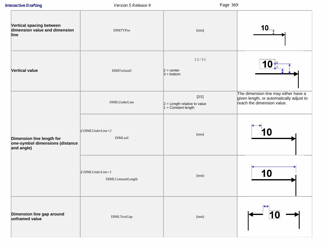
Vertical spacing betweendimension value and dimensionline
DIMTYPos (mm)
Vertical value DIMTxtJustif
[ 2 / 3 ]
2 = center3 = bottom
Dimension line length forone-symbol dimensions (distanceand angle)
DIMLUnderLine
[2/1]
2 = Length relative to value1 = Constant length
The dimension line may either have agiven length, or automatically adjust toreach the dimension value.
if DIMLUnderLine=2
DIMLtail(mm)
if DIMLUnderLine=1
DIMLConstantLength(mm)
Dimension line gap aroundunframed value DIMLTextGap (mm)

Dimension line gap around framedvalue DIMLFrameGap
(mm)
Symbol reversal mode SYMBReverseMode
[ 1 / 2 / 3 ]
1 = always inside2 = always outside 3 = automatic (based on value position)
This overall parameter is not takeninto account, but is overriden on
each dimension Properties.
Symbol reversal limit SYMBReverselimit (mm)
Size of dimension valueunderlining
SCORLeftTail
SCORRightTail
SCORVertSpace
(mm)
Dimension and Leader SymbolsParameters Parameter Names Values Descriptions
Arrow size and angle(symbol type #1)
SYMBArrowSide (mm)
SYMBArrowAngle (degrees)

Closed arrow size and angle(symbol type #2)
SYMBClosedArrowSide (mm)
SYMBClosedArrowAngle (degrees)
Filled arrow size and angle(symbol type #3)
SYMBFilledArrowSide (mm)
SYMBFilledArrowAngle (degrees)
Symetric arrow size and angle(symbol type #4)
SYMBSymetricArrowSide (mm)
SYMBSymetricArrowAngle (degrees)
Slash size(aymbol type #5) SYMBSlashLength (mm)
Circle size(symbol type #6) SYMBCircleDiameter (mm)

Filled circle size(symbol type #7) SYMBFilledCircleDiameter (mm)
Scored circle size(symbol type #8) SYMBSymetricCircleDiameter (mm)
Crossed circle size(symbol type #9) SYMBCrossCircleDiameter (mm)
Triangle size(symbol type #10) SYMBTriangleSide (mm)
Filled triangle size(symbol type #11) SYMBFilledTriangleSide (mm)
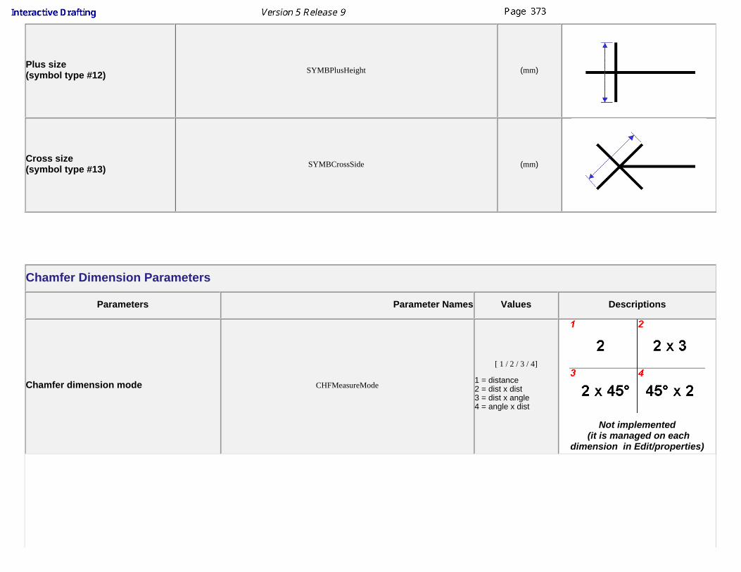
Plus size(symbol type #12) SYMBPlusHeight (mm)
Cross size(symbol type #13) SYMBCrossSide (mm)
Chamfer Dimension Parameters
Parameters Parameter Names Values Descriptions
Chamfer dimension mode CHFMeasureMode
[ 1 / 2 / 3 / 4]
1 = distance2 = dist x dist3 = dist x angle4 = angle x dist
Not implemented (it is managed on each
dimension in Edit/properties)

Chamfer dimension representation
(separate parameter depending on theCHFMeasureMode parameter value)
if CHFMeasureMode=1
CHFRepModeDist
if CHFMeasureMode=2
CHFRepModeDistDist
if CHFMeasureMode=3
CHFRepModeDistAngle
if CHFMeasureMode=4
CHFRepModeAngleDist
[ 1 / 2 / 3 ]
1 = 1 symbol - 1 part2 = 1 symbol - 2 parts3 = 2 symbols
Not implemented (it is managed on each
dimension in Edit/properties)
Chamfer separator font height CHFSepHeight (mm)
Chamfer Value Framing CHFFrameGroup
[ 1 / 2 ]
1 = separately2 = as a whole
Half Dimensions
Parameters Parameter Names Values Descriptions

Half dimension dimension line extent(if the value is inside)
HLFIntOverrunMode
[ 1 / 2 / 3 ]
1 = till Axis2 = under value3 = over axis
if HLFIntOverrunMode=3
HLFIntOverrun(mm)
Half-dimension dimension line extent(if the value is outside)
HLFExtOverrunMode
[ 1 / 2 ]
1 = till axis2 = constant overrun
if HLFextOverrunMode=2
HLFExtOverrun(mm)

Dimension Associated Texts
Parameters Parameter Names Values Descriptions
Point to be used on the associatedtext as a reference for positioning
ASTBeforePosReference7 = top8 = center9 = bottom
reference for positioning
for Before/After/Insert texts
for Upper/Lower texts
ASTAfterPosReference1 = top2 = center3 = bottom
ASTInsertPosReference1 = top2 = center3 = bottom
ASTUpperPosReference1 = left4 = center7 = rigth
ASTLowerPosReference3 = left6 = center9 = right
Horizontal and vertical offsets forpositioning
ASTBeforeXDistASTBeforeYDistASTAfterXDistASTAfterYDistASTInsertXDistASTInsertYDistASTUpperXDistASTUpperYDistASTLowerXDistASTLowerYDist
(mm)

Annotations
Parameters Parameter Names Values Descriptions
Text angle TXTAngleAllowed
[ 1 / 2 ]
1 = 0 to 360 degrees2 = -90 to 90 degrees
Text leaders size
TXTLeaderLeftTail (side of leader)TXTLeaderRightTail (side opposite to leader)
TXTLeaderVertSpace(mm)
TXTLeaderGap (mm)
Text thickness(for compatibility with V4)Warning: does not work on bold text (setat 0,7 mm), on complex text androughness annotations.
TXTThickness
(mm)
Datum feature leaderrepresentation mode TXTDatumMode
[ 1 / 2 ]
1 = Normal2 = Flag

Fake dimensions
Parameters Parameter Names Values Descriptions
Fake dimension value display
FAKIdentifyMode
[ 1 / 2 / 4 ]
1 = underline2 = parenthesis4 = none
Not implemented (it is managed on each dimension in Edit/properties)
If FAKIdentifyMode=1
FAKUnderlineTailFAKVerticalOffset
(mm)
Dual Dimensions
Parameters Parameter Names Values Descriptions
Dual dimension separatorheight, for side-by-side dualdisplay mode
DUASideSepHeight (mm)
Dual dimension display, forvalues above-one-another
DUAAboveOffsetDUAAboveSpace (mm)
DUAPosReference
[ 1 / 2 / 3 ]
1 = top2 = center3 = bottom

display mode
DUAJustification
[ 1 / 2 / 3 ]
1 = left2 = center3 = right
Cumulate Dimensions (Ordinate Dimensions)
Parameters Parameter Names Values Descriptions
Cumulate dimensions signdisplay CUMLSignDisplay
[ 1 / 2 / 3 ]
1 = no sign3 = positive sign on all values
Origin symbol shape andsize sign
CUMLOriginSymbol
[ 0 / ... / 13 ]
0 = none1-13 = refer to "dimension line symbols" table
CUMLSymbolScale (real)
Display of origin zero CUMLZeroDisplay
[ 2 / 1 ]
2 = display1= no display
Extension line display CUMLExtLDisplay
[ 2 / 1 ]
2 = display1= no display
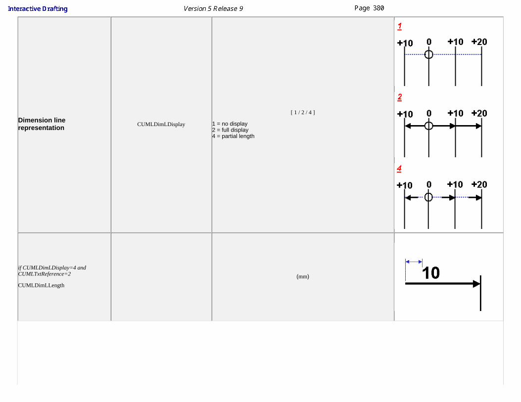
Dimension linerepresentation CUMLDimLDisplay
[ 1 / 2 / 4 ]
1 = no display2 = full display4 = partial length
if CUMLDimLDisplay=4 andCUMLTxtReference=2
CUMLDimLLength
(mm)

Value orientation reference CUMLTxtReference
[ 1 / 2 ]
1 = dimension line2 = extension line
if CUMLTxtReference=1
if CUMLTxtReference=2
Dimension line length(only If CUMLTxtReference=1)
CUMLDimLinMode=2 dimension line from the origin
CUMLDimLinMode=4constant dimension line
(mm)
CUMLDimLinMode=3dimension line overruns the text box
(mm)

Value orientationCUMLTxtOrient
[ 1 / 2 / 3 ]
1 = parallel2 = perpendicular3 = angle
if CUMLTxtOrient=3
CUMLTxtAngle(degrees)
Cumulate dimensionextension line length andtext position
CUMLExtMode
[ 3 / 4 ]
3 = relative to text box4 = constant
if CUMLExtMode=3
CUMLExtLOver(mm)
if CUMLExtMode=4
CUMLExtLLength(mm)
if CUMLExtMode=4 CUMLExtLTxtVPos (mm)
if CUMLExtMode=3 CUMLDimLTxtVPos (mm)
if CUMLExtMode=4 CUMLExtLTxtRef Not yet implemented
if CUMLExtMode=3
CUMLTxtVJusti1Not yet implemented
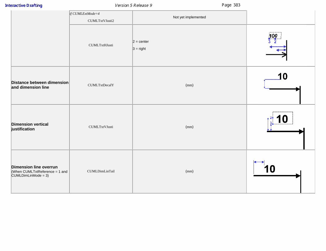
if CUMLExtMode=4
CUMLTxtVJusti2Not yet implemented
CUMLTxtHJusti2 = center
3 = right
Distance between dimensionand dimension line CUMLTxtDecalY (mm)
Dimension verticaljustification CUMLTxtVJusti (mm)
Dimension line overrun(When CUMLTxtReference = 1 andCUMLDimLinMode = 3)
CUMLDimLinTail (mm)

Style DefinitionsThis section deals with descriptions, which are user-defined styles to be applied to dimensions.
An additional style can be created by using the "Add Instance" button available when selecting the style type in the standards editor (Tolerance Formats or ValueFormats). This will create a sample style definition that you need to select and customize to suit your needs.
Once defined, a format can be applied to dimensions just as any dimension attribute, either using the Edit/Properties, or using the Dimension Property Toolbar.
The available types of descriptions are:
Dimension tolerance styles1. Dimension value display styles2.
Dimension Tolerance Styles
These parameters are located in the node "Tolerance formats" of the standard file.
The tolerance format parameters drive the representation of a dimension tolerance, and includes parameters such as:Type of tolerance (numerical/alphanumerical)Separator between valuesposition relatively to dimension valuefont size for tolerancetrailing zeros display for numerical typeand so forth.
See Tolerance Style Parameters table.
Dimension Value Display Styles
These parameters are located in the node "Value Formats" of the standard file.
The dimension value display style parameters drive the representation of a dimension value, and includes parameters such as:multiplying factorseparators for thousandsposition relatively to dimension linedisplay of fractional valuestrailing zeros displayand so forth.
See Numerical Display Style Parameters table.
To create a new tolerance style or a new dimension display, you must use the Standards editor, and add a new instance of a Tolerance or dimension displaystyle. Once the instance is created, you can customize its definition by modifying one or several values of the parameters defining the style

Parameters defining a tolerance styleTolNameTolTypeTolSepar_1TolSepar_2TolSepTo_1TolSepTo_2TolSepTo_3TolFractLineTolSymbolHTolScaleTolPtOnValueTolAnchorPtTolExtXTolExtYTolIntXTolIntYTolTrailingTolMergeSameTolShowNull
Parameters defining a dimension display styleNDNameNDTypeNDUnitNDFactNDExiseNDNulFac_1NDNulFac_2NDNulFac_3NDSepar_1NDSepar_2NDSepar_3NDNulOtherNDAlignFracNDTypFracNDFinZerNDSepNumNDSep1000NDGlobFactNDFact_1NDFact_2NDFact_3NDValPos_1NDValPos_2NDValPos_3NDSepPos_1NDSepPos_2NDSepPos_3NDSepScl_1NDSepScl_2NDSepScl_3NDResSclNDRestXNDRestYNDOperYNDSepDen
For information about the parameters see parameters descriptions.
Define a new Tolerance styleIn this scenario you will create a new style for dimension tolerancesYou want to create this new style, with superimposed tolerance values and parenthesis as separators
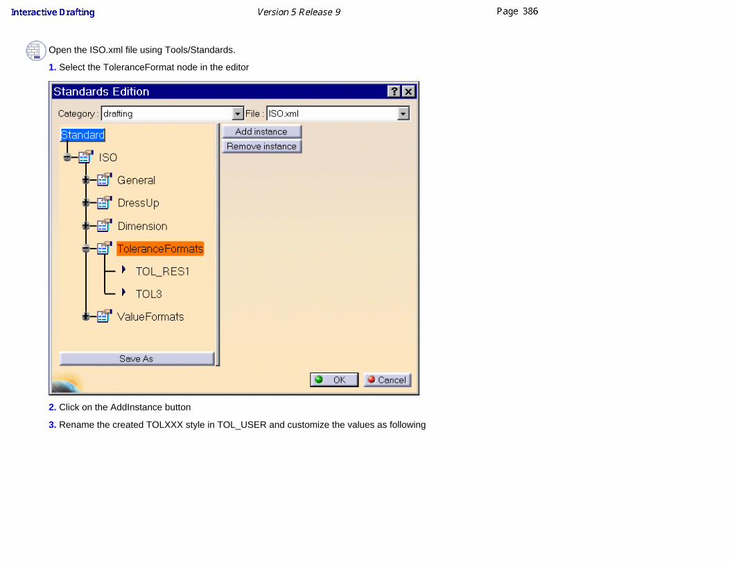
Open the ISO.xml file using Tools/Standards.
1. Select the ToleranceFormat node in the editor
2. Click on the AddInstance button
3. Rename the created TOLXXX style in TOL_USER and customize the values as following

4. Click OK to Save the ISO.xml file
5. Create a new ISO drawing. The new tolerance style will appear in the tolerance combo box

You must set every parameters.You must use the symbol used by the computer system to set a parameter to a real value ("," or ".").Note: you can use a fraction to set a parameter.
Tolerance StylePARAMETER PARAMETER NAME VALUES DESCRIPTION
Tolerance Format Name TolName (8 char string) This the user-defined name that willbe used as the description identifier
Tolerance Format TypeToltype
[ 1 / 2 / 3 / 4 / 5 / 6 / 7 ]
1 = Numerical side by side
2 = Numerical super-imposed
3 = Resolved Numerical side by side
4 = Resolved numerical super-imposed

5 =Alphanumerical Single Value
6 = Alphanumerical side by side
7 = Alphanumerical super-imposed
Separators forsuper-imposedtolerances
Before
TolSepar_1 [0...18 ]
separator number as described in the SeparatorCharacter TableAfter
TolSepar_2
Separators forside-by-side tolerances
Before
TolSepTo_1 [0...18 ]
separator number as described in the SeparatorCharacter Table
Between
TolSepTo_2
After
TolSepTo_3

Fraction line onsuper-imposedtolerances
TolFractLine
[2/1]
2= Fraction line
1= No fraction line
Separator CharacterSize (Ratio betweenSeparator Character andValue Text font sizes)
TolSymbolH
(real)
= separator height / value height
( = B / A )
Tolerance Size (Ratio betweenTolerance Text andValue Text font sizes)
TolScale
(real)
= tolerance height / value height
( = C / A )
Tolerance PositionAnchor Point (for offsetcomputing)
TolPtOnValue
[ 7 / 8 / 9 ]
7 =Top
8 = Middle
9 = Bottom
TolAnchorPt
[ 1 / 2 / 3 ]
1 =Top
2 = Middle
3 = Bottom
Offset betweendimension value andtolerance
TolExtX
(mm)
TolExtY

Offset between the 2tolerance values
TolIntX
(mm)
TolIntY
Display of tolerancetrailing zeros TolTrailing
[ 0 / 1 / 2 ]
0 = Display (number of digits specified in the valueprecision)1 = No Display2 = Same "display" mode as the dimension value
Display of identicalTolerance Values( for numericaltolerances only)
TolMergeSame
[ 1 / 2 ]
1 = Display common value2 = Display separate values
Display of null ToleranceValues( for numericaltolerances only)
TolShowNull
[ 1 / 2 / 3 ]
1 = Display null value with sign
2 = Display null value without sign
3 = No Display of null value

Separator Character Table
This table lists the characters that can be used as separators before, between or after the tolerance values
Separators
Symbol # Character00 (none)
01 /02 :03 (04 )05 "06 ,07 <08 >09 X10 *11 .12 ;13 +14 [15 ]16 -17 _18 (space)
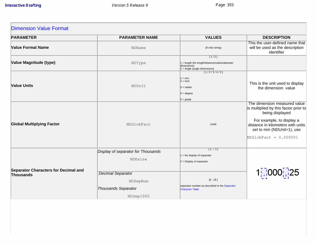
Dimension Value FormatPARAMETER PARAMETER NAME VALUES DESCRIPTION
Value Format Name NDName (8 char string)This the user-defined name thatwill be used as the description
identifier
Value Magnitude (type) NDType
[ 1 / 2 ]
1 = length (for length/distance/radius/diameterdimensions)2 = Angle (angle dimensions)
Value Units NDUnit
[ 1 / 2 / 3 / 4 / 5 ]
1 = mm2 = inch
3 = radian
4 = degree
5 = grade
This is the unit used to displaythe dimension value
Global Multiplying Factor NDGlobFact (real)
The dimension measured valueis multiplied by this factor prior to
being displayed
For example, to display adistance in kilometers with units
set to mm (NDUnit=1), use
NDGlobFact = 0.000001
Separator Characters for Decimal andThousands
Display of separator for Thousands
NDExise
[ 1 / 2 ]
1 = No display of separator
2 = Display of separator
Decimal Separator
NDSepNum
Thousands Separator
NDSep1000
[0...18 ]
separator number as described in the SeparatorCharacter Table

Display of Trailing Zeros NDFinZer
[ 1 / 2 ]
1 = No display of trailing zeros
2 = Display of trailing zeros (number of digits specified inthe value precision)
Fractional Rest Justification NDAlignFrac Not yet implemented
Fractional Rest Display Mode NDTypFrac
[ 1 / 2 ]
1 = Side by side
2 = Super-imposed
Fractional Rest Height Ratio NDResScl
(real)
= Unit height / value height
( = B / A )
Fractional Rest Positioning Offsets(the horizontal offset also applies to decimalrests)
NDRestX(real)
This value is a ratio to the character height
NDRestY

Offset between Fractional Rest Numeratorand Denominator NDOperY
(real)
This value is a ratio to the character height
Position of Last Term Unit NDSepDen
[ 1 / 2 ]
1 = Before fractional rest
2 = After fractional rest
Number of Terms in the Value NDFact [ 1...3 ]
Definition of each of the value terms
A value can be made of up to three terms plus a rest. All of the following parameters, suffixed by the term number, apply to each of the possible 3 terms. The numbering of the terms goes from right to left, #1 being the right most term
PARAMETER PARAMETER NAME VALUES DESCRIPTION

Display of null Terms and LeadingZeros
NDNulFac_1NDNulFac_2NDNulFac_3
[ 1 / 2 ]
1 = No display of zeros
2 = Display of zeros
NDNulOther
[ 1 / 2 ]
1 = No display of zeros
2 = Display of zeros
Term Multiplying FactorNDFact_1NDFact_2NDFact_3
( real )
The term measured value is multiplied by this factor prior to being displayed (the globalmultiplying factor is also used). All 3 values must have increasing and distinct values.
Example: to display a value with a term in centimeters and a term in millimeters, withNDUnit=mm and NDGlobFact=1, set
NDFact_1 = 1 NDFact_2 = 10
Term Unit SuffixNDSepar_1NDSepar_2NDSepar_3
(16 char string)
Term Unit Height RatioNDSepScl_1NDSepScl_2NDSepScl_3
(real)
= Unit height / value height
( = B / A )
Term Vertical Positioning Offset(relatively to the left-most term)
NDValPos_1NDValPos_2NDValPos_3
(mm)

Term Unit Vertical Positioning Offset(relatively to its term)
NDSepPos_1NDSepPos_2NDSepPos_3
(mm)
Upgrading Standard Files from Previous ReleasesIn V5R9, the format of the standard file has changed, the standard file defining standard XXX is now a file named XXX.xml and is located ininstall_root/resources/standard/drafting (Up to and including V5R8, the standard file defining standard XXX was a file named XXX.CATDrwStandard and located ininstall_root/reffiles/Drafting)
If you have customized or defined a CATDrwStandard files, and wish to re-use this customization in V5R9, you need to convert your CATDrwStandard file into a xmlfile. There are 2 ways to do this:
Manual upgradeIf the degree of customization of the standard file is small, you can start from one of the 4 pre-defined standard files (ISO, ANSI, JIS or ASME), and modify it usingthe standards editor (Tools/Standards). You will need to modify the parameters values, and add the styles that you had defined in the CATDrwStandard file.
Automatic upgradeA batch utility is provided in order to automatically generate the V5R9 XXX.xml file starting from a XXX.CATDrwStandard file. All the customization done on theCATDrwStandard file will be reproduced in the xml file, and all styles defined in CATDrwStandard file will be added.Also the utility will add the new V5R9 specific parameters in the xml files with default values, as well as the new V5R9 pre-defined styles.if you want to convert a single CATDrwStandard to the new V5R9 format ,type CATAnnStandardTools MIGRATE XXX [dir].
If you want to convert all CATDrwStandard files to the new V5R9 format, type CATAnnStandardTools MIGRATE_ALL [dir]
How to use the standard upgrade tool on WindowsOpen an MS-DOS Window.1. Change to the folder in which you installed the product.
The default folder is C:\Program Files\Dassault Systemes\B09\OS_a\code\bin
where "OS_a" is:intel_a (Windows NT and Windows 2000)win_a (Windows 98).
2.
Enter this command to generate xml files for all the CATDrwStandard files located in reffiles\Drafting3.
CATAnnStandardTools MIGRATE_ALL [dir]
where:[dir] is an optional directory in which to write the resulting xml files. Local directory is the default

or enter this command to generate the xml file corresponding to one single standard
CATAnnStandardTools MIGRATE XXX [dir]
where: XXX is the name of the standard you want to convert (ISO, ANSI...)[dir] is an optional directory in which to write the resulting xml files. Local directory is the default
How to use the standard upgrade tool on UNIX
Open an shell command window.1. Change to the directory in which you installed the product.
The default directory is /usr/DassaultSystemes/B09/OS_a/code/command/
where "OS_a" is:aix_ahpux_airix_asolaris_a
2.
Enter this command to generate xml files for all the CATDrwStandard files located in reffiles\Drafting3.
./catstart -run "CATAnnStandardTools MIGRATE_ALL [dir]"
where:[dir] is an optional directory in which to write the resulting xml files. Local directory is the default
or enter this command to generate the xml file corresponding to one single standard
./catstart -run "CATAnnStandardTools MIGRATE XXX [dir]"
where: XXX is the name of the standard you want to convert (ISO, ANSI...)[dir] is an optional directory in which to write the resulting xml files. Local directory is the default
General Syntax for the standard editor valuesFractions and operations
The standards editor can handle basic numerical operations to help you enter the values for the parameters. You can enter your value as a set of operations, and letthe user interface compute the result when you validate the field.
For example, for each parameter of type "real" you can specify the value using a fraction:
NDFact_1 = 1/60.
You can also use units or trigonometric functions in your operations:

NDSepPos_1 = 1 in + 1 mm + cos(0.12)
Special characters
For each parameter of type "string", you can enter special characters by using the following keywords[DEGREE] will be displayed as º[MINUTE] will be displayed as '[SECOND] will be displayed as "
The special character can be used alone or combined with other characters (the special character only counts as 1 character):
NDSepar_1 , [DEGREE]
or
NDSepar_1 , " in [DEGREE]"
Predefined StylesSome basic styles are provided by default, in two different ways:
Non modifiable styles They are not defined in the standard file, but in the code itself. They cannot be modified, but can be taken out of the list of available styles by using the Allowed*parameters described in the General Parameters section. All styles provided up to V5R8 are of this type.
For Tolerance styles
TOL_NUM2
ANS_NUM2
DIN_NUM2
SGL_NUM2
INC_NUM2
TOL_RES2
TOL_ALP1
TOL_ALP2
TOL_ALP3
TOL_0.7
TOL_1.0
For Value Display styles
NUM.DIMM
NUM,DIMM
NUM.DINC
NUM.DIMP
ANS.DIMM
DISTMM
DISTINCH
FEET-INC
NUM.ADMS
NUM,ADMS
INC.ADMS

ISONUM
ISOALPH1
ISOALPH2
CPL_FLA1
CPL_FLA3
CPL_50A1
CPL_50A3
CPL_75A1
CPL_75A3
NUM.ARAD
ANGLEDEC
ANGLEDMS
The following table lists these non-modifiable styles, along with an example of the result when applied on a dimension. The right-most column contains a link to thestyle definition, which enables to derive new styles from them, by just copying whole or part of their definition.
Value Display styles
NAME DISPLAY DESCRIPTION LINK TO THE STYLE DEFINITION
NUM.DIMM Millimeters with dot Click here
NUM,DIMM Millimeters with comma Click here
NUM.DINC inches with trailing zeros Click here

NUM.DIMP inches with unit display Click here
ANS.DIMM Millimeters with trailing zeros Click here
DISTMM Millimeters with dot Click here
DISTINC inches with unit display Click here
FEET-INC feet and inch with unit display Click here
NUM.ADMS Degrees/minutes/seconds withdot Click here
NUM,ADMS Degrees/minutes/seconds withcomma Click here

INC.ADMS Degrees/minutes/seconds withdot and trailing zeros Click here
NUM.ARAD radians Click here
ANGLEDEC Degrees with decimal format Click here
ANGLEDMS Degrees/minutes/seconds withdot Click here
Tolerance styles
NAME DISPLAY DESCRIPTION LINK TO THE DEFINITION FILE
TOL_NUM2 Numerical superimposed(small) Click here
ANS_NUM2 Numerical superimposed withtrailing zeros (large) Click here

DIN_NUM2 Numerical superimposed(small) Click here
SGL_NUM2Numerical superimposed withtrailing zeros and parentheses
(small)Click here
INC_NUM2 Numerical superimposed (large) Click here
TOL_RES2 Numerical resolved Click here
TOL_ALP1 Alphanumerical single value(large) Click here
TOL_ALP2 Alphanumerical double valueside-by-side (large) Click here
TOL_ALP3 Alphanumerical double valuesuperimposed (small) Click here

TOL_0.7 Numerical superimposed(small) Click here
TOL_1.0 Numerical superimposed(small) Click here
ISONUMNumerical superimposed withtrailing zeros and parentheses
(large)Click here
ISOALPH1 Alphanumerical single value(large) Click here
ISOALPH2 Alphanumerical double valuesuperimposed (small) Click here
CPL_FLA1 Alphanumerical single value(large) Click here
CPL_FLA3 Alphanumerical double valuesuperimposed (large) Click here

CPL_50A1 Alphanumerical single value(small) Click here
CPL_50A3 Alphanumerical double valuesuperimposed (small) Click here
CPL_75A1 Alphanumerical single value(medium) Click here
CPL_75A3 Alphanumerical double valuesuperimposed (medium) Click here
Pre-defined stylesThey appear in the default standard files provided by DS, just as any company defined style would appear. They can be modified or deleted using the StandardsEditor, or taken out of the list of available styles by using the Allowed* parameters described in the General Parameters section.
For Tolerance styles
TOL_RES1
For Value Display styles
micron
mm
cm
m
km
in
ftinch
grade

Predefined styles definition
TolName= TOL_NUM2TolType= 2TolSepar_1= 0TolSepar_2= 0TolSymbolH= 1.0TolSepTo_1= 0TolSepTo_2= 0TolSepTo_3= 0TolTrailing= 2TolFractLine= 1TolPtOnValue= 8TolAnchorPt= 2TolIntX= 0.0TolIntY= 0.6TolExtX= 0.6TolExtY= 0.0TolMergeSame= 1TolShowNull= 2TolScale= 0.7
TolName= ANS_NUM2TolType= 2TolSepar_1= 0TolSepar_2= 0TolSymbolH= 1.0TolSepTo_1= 0TolSepTo_2= 0TolSepTo_3= 0TolTrailing= 0TolFractLine= 1TolPtOnValue= 8TolAnchorPt= 2TolIntX= 0.0TolIntY= 0.6TolExtX= 0.6TolExtY= 0.0TolMergeSame= 1TolShowNull= 2TolScale= 1.0

TolName= DIN_NUM2TolType= 2TolSepar_1= 0TolSepar_2= 0TolSymbolH= 1.0TolSepTo_1= 0TolSepTo_2= 0TolSepTo_3= 0TolTrailing= 2TolFractLine= 1TolPtOnValue= 8TolAnchorPt= 2TolIntX= 0.0TolIntY= 0.6TolExtX= 0.6TolExtY= 0.0TolMergeSame= 1TolShowNull= 3TolScale= 0.7
TolName= SGL_NUM2TolType= 2TolSepar_1= 3TolSepar_2= 4TolSymbolH= 2.0TolSepTo_1= 0TolSepTo_2= 0TolSepTo_3= 0TolTrailing= 0TolFractLine= 1TolPtOnValue= 8TolAnchorPt= 2TolIntX= 0.0TolIntY= 0.6TolExtX= 0.6TolExtY= 0.0TolMergeSame= 1TolShowNull= 2TolScale= 0.7

TolName= INC_NUM2TolType= 2TolSepar_1= 0TolSepar_2= 0TolSymbolH= 1.0TolSepTo_1= 0TolSepTo_2= 0TolSepTo_3= 0TolTrailing= 2TolFractLine= 1TolPtOnValue= 8TolAnchorPt= 2TolIntX= 0.0TolIntY= 0.6TolExtX= 0.6TolExtY= 0.0TolMergeSame= 1TolShowNull= 1TolScale= 1.0
TolName= TOL_RES2TolType= 4TolSepar_1= 0TolSepar_2= 0TolSymbolH= 1.0TolSepTo_1= 0TolSepTo_2= 0TolSepTo_3= 0TolTrailing= 2TolFractLine= 1TolPtOnValue= 9TolAnchorPt= 3TolIntX= 0.0TolIntY= 0.6TolExtX= 0.0TolExtY= 0.0TolMergeSame= 1TolShowNull= 2TolScale= 1.0

TolName= TOL_ALP1TolType= 5TolSepar_1= 0TolSepar_2= 0TolSymbolH= 1.0TolSepTo_1= 0TolSepTo_2= 0TolSepTo_3= 0TolTrailing= 0TolFractLine= 0TolPtOnValue= 9TolAnchorPt= 3TolIntX= 0.0TolIntY= 0.0TolExtX= 0.6TolExtY= 0.0TolMergeSame= 0TolShowNull= 0TolScale= 1.0
TolName= TOL_ALP2TolType= 6TolSepar_1= 0TolSepar_2= 0TolSymbolH= 1.0TolSepTo_1= 0TolSepTo_2= 1TolSepTo_3= 0TolTrailing= 0TolFractLine= 0TolPtOnValue= 9TolAnchorPt= 3TolIntX= 0.6TolIntY= 0.0TolExtX= 0.6TolExtY= 0.0TolMergeSame= 0TolShowNull= 0TolScale= 1.0

TolName= TOL_ALP3TolType= 7TolSepar_1= 0TolSepar_2= 0TolSymbolH= 1.0TolSepTo_1= 0TolSepTo_2= 0TolSepTo_3= 0TolTrailing= 0TolFractLine= 1TolPtOnValue= 8TolAnchorPt= 2TolIntX= 0.0TolIntY= 0.6TolExtX= 0.6TolExtY= 0.0TolMergeSame= 0TolShowNull= 0TolScale= 0.7
TolName= TOL_0.7TolType= 2TolSepar_1= 0TolSepar_2= 0TolSymbolH= 1.0TolSepTo_1= 0TolSepTo_2= 0TolSepTo_3= 0TolTrailing= 2TolFractLine= 1TolPtOnValue= 9TolAnchorPt= 3TolIntX= 0.0TolIntY= 0.250000TolExtX= 0.5TolExtY= 0.0TolMergeSame= 1TolShowNull= 3TolScale= 0.715000
TolName= TOL_1.0

TolType= 2TolSepar_1= 0TolSepar_2= 0TolSymbolH= 1.0TolSepTo_1= 0TolSepTo_2= 0TolSepTo_3= 0TolTrailing= 2TolFractLine= 1TolPtOnValue= 9TolAnchorPt= 3TolIntX= 0.0TolIntY= 0.5TolExtX= 0.5TolExtY= 0.0TolMergeSame= 1TolShowNull= 2TolScale= 1.0
TolName= ISONUMTolType= 2TolSepar_1= 3TolSepar_2= 4TolSymbolH= 2.5TolSepTo_1= 0TolSepTo_2= 0TolSepTo_3= 0TolTrailing= 0TolFractLine= 1TolPtOnValue= 9TolAnchorPt= 3TolIntX= 0.0TolIntY= 0.5TolExtX= -0.5TolExtY= 0.0TolMergeSame= 2TolShowNull= 2TolScale= 1.0
TolName= ISOALPH1TolType= 5

TolSepar_1= 0TolSepar_2= 0TolSymbolH= 1.0TolSepTo_1= 0TolSepTo_2= 0TolSepTo_3= 0TolTrailing= 0TolFractLine= 0TolPtOnValue= 9TolAnchorPt= 3TolIntX= 0.0TolIntY= 0.5TolExtX= 0.5TolExtY= 0.0TolMergeSame= 0TolShowNull= 0TolScale= 1.0
TolName= ISOALPH2TolType= 7TolSepar_1= 0TolSepar_2= 0TolSymbolH= 1.0TolSepTo_1= 0TolSepTo_2= 0TolSepTo_3= 0TolTrailing= 0TolFractLine= 1TolPtOnValue= 9TolAnchorPt= 3TolIntX= 0.0TolIntY= 0.250000TolExtX= 0.5TolExtY= 0.0TolMergeSame= 0TolShowNull= 0TolScale= 0.715000
TolName= CPL_FLA1TolType= 5TolSepar_1= 0

TolSepar_2= 0TolSymbolH= 25.4TolSepTo_1= 0TolSepTo_2= 0TolSepTo_3= 0TolTrailing= 0TolFractLine= 0TolPtOnValue= 9TolAnchorPt= 3TolIntX= 0.0TolIntY= 0.0TolExtX= 0.285714TolExtY= 0.0TolMergeSame= 0TolShowNull= 0TolScale= 1.0
TolName= CPL_FLA3TolType= 7TolSepar_1= 0TolSepar_2= 0TolSymbolH= 1.0TolSepTo_1= 0TolSepTo_2= 0TolSepTo_3= 0TolTrailing= 0TolFractLine= 1TolPtOnValue= 8TolAnchorPt= 2TolIntX= 0.0TolIntY= 0.5TolExtX= 0.285714TolExtY= 0.0TolMergeSame= 0TolShowNull= 0TolScale= 1.0
TolName= CPL_50A1TolType= 5TolSepar_1= 0TolSepar_2= 0

TolSymbolH= 25.4TolSepTo_1= 0TolSepTo_2= 0TolSepTo_3= 0TolTrailing= 0TolFractLine= 0TolPtOnValue= 9TolAnchorPt= 3TolIntX= 0.0TolIntY= 0.0TolExtX= 0.214286TolExtY= 0.250000TolMergeSame= 0TolShowNull= 0TolScale= 0.5
TolName= CPL_50A3TolType= 7TolSepar_1= 0TolSepar_2= 0TolSymbolH= 1.0TolSepTo_1= 0TolSepTo_2= 0TolSepTo_3= 0TolTrailing= 0TolFractLine= 1TolPtOnValue= 8TolAnchorPt= 2TolIntX= 0.0TolIntY= 0.250000TolExtX= 0.214286TolExtY= 0.0TolMergeSame= 0TolShowNull= 0TolScale= 0.5
TolName= CPL_75A1TolType= 5TolSepar_1= 0TolSepar_2= 0TolSymbolH= 25.4

TolSepTo_1= 0TolSepTo_2= 0TolSepTo_3= 0TolTrailing= 0TolFractLine= 0TolPtOnValue= 9TolAnchorPt= 3TolIntX= 0.0TolIntY= 0.0TolExtX= 0.250000TolExtY= 0.125000TolMergeSame= 0TolShowNull= 0TolScale= 0.750000
TolName= CPL_75A3TolType= 7TolSepar_1= 0TolSepar_2= 0TolSymbolH= 25.4TolSepTo_1= 0TolSepTo_2= 0TolSepTo_3= 0TolTrailing= 0TolFractLine= 1TolPtOnValue= 8TolAnchorPt= 2TolIntX= 0.0TolIntY= 0.375000TolExtX= 0.250000TolExtY= 0.0TolMergeSame= 0TolShowNull= 0TolScale= 0.750000
NDName= NUM.DIMMNDType= 1NDUnit= 1NDGlobFact= 1.0NDNulFac_1= 1NDNulFac_2= 2

NDNulFac_3= 1NDExise= 1NDSep1000= 0NDFact_1= 1.0NDFact_2= 0.0NDFact_3= 0.0NDValPos_1= 0.0NDValPos_2= 0.0NDValPos_3= 0.0NDSepar_1= NDSepar_2= NDSepar_3= NDSepScl_1= 1.0NDSepScl_2= 0.0NDSepScl_3= 0.0NDSepPos_1= 0.0NDSepPos_2= 0.0NDSepPos_3= 0.0NDRestY= 0.0NDFinZer= 1NDSepNum= 11NDTypFrac= 2NDSepDen= 2NDOperY= 0.5NDNulOther= 1NDResScl= 1.0NDFact= 1NDRestX= 0.5
NDName= NUM,DIMMNDType= 1NDUnit= 1NDGlobFact= 1.0NDNulFac_1= 1NDNulFac_2= 2NDNulFac_3= 1NDExise= 1NDSep1000= 0NDFact_1= 1.0NDFact_2= 0.0NDFact_3= 0.0NDValPos_1= 0.0NDValPos_2= 0.0

NDValPos_3= 0.0NDSepar_1= NDSepar_2= NDSepar_3= NDSepScl_1= 1.0NDSepScl_2= 0.0NDSepScl_3= 0.0NDSepPos_1= 0.0NDSepPos_2= 0.0NDSepPos_3= 0.0NDRestY= 0.0NDFinZer= 1NDSepNum= 6NDTypFrac= 2NDSepDen= 2NDOperY= 0.5NDNulOther= 1NDResScl= 1.0NDFact= 1NDRestX= 0.5
NDName= NUM.DINCNDType= 1NDUnit= 2NDGlobFact= 1.0NDNulFac_1= 1NDNulFac_2= 1NDNulFac_3= 1NDExise= 1NDSep1000= 0NDFact_1= 1.0NDFact_2= 0.0NDFact_3= 0.0NDValPos_1= 0.0NDValPos_2= 0.0NDValPos_3= 0.0NDSepar_1= NDSepar_2= NDSepar_3= NDSepScl_1= 1.0NDSepScl_2= 0.0NDSepScl_3= 0.0NDSepPos_1= 0.0
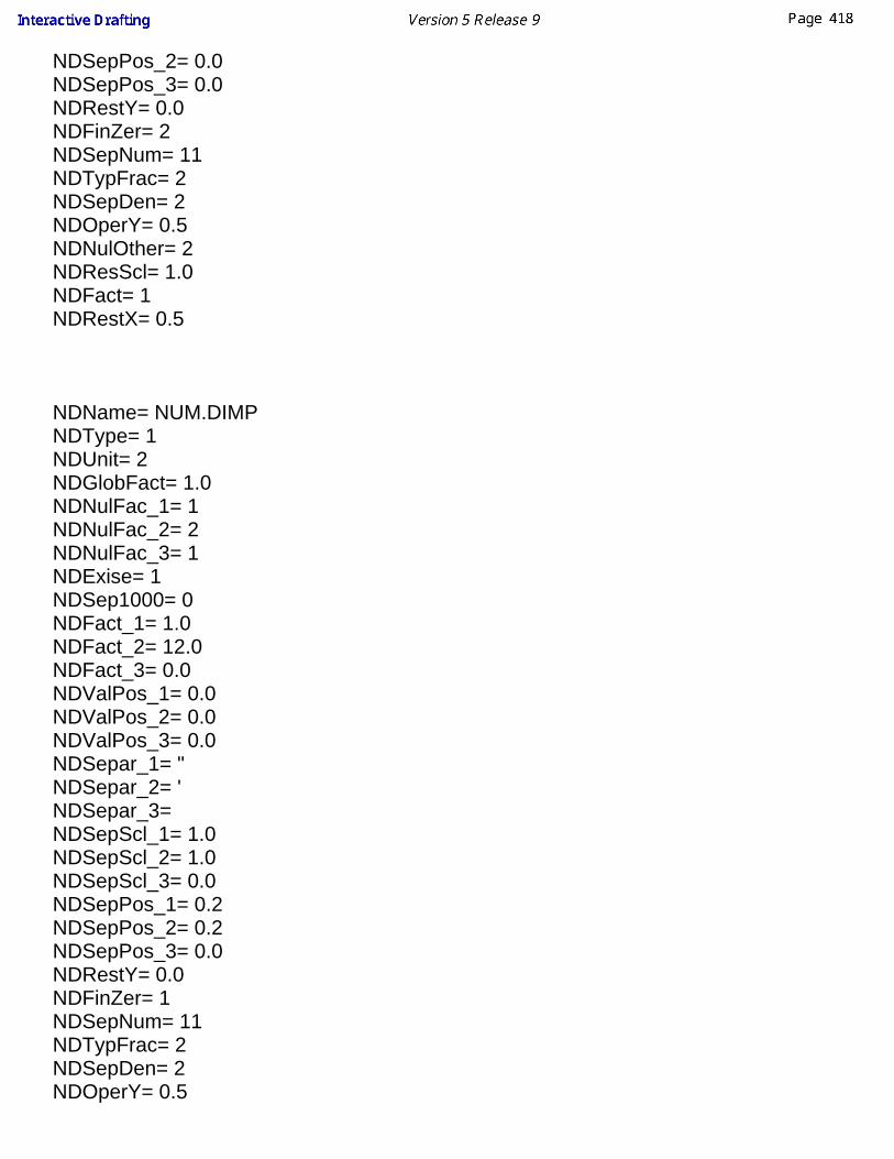
NDSepPos_2= 0.0NDSepPos_3= 0.0NDRestY= 0.0NDFinZer= 2NDSepNum= 11NDTypFrac= 2NDSepDen= 2NDOperY= 0.5NDNulOther= 2NDResScl= 1.0NDFact= 1NDRestX= 0.5
NDName= NUM.DIMPNDType= 1NDUnit= 2NDGlobFact= 1.0NDNulFac_1= 1NDNulFac_2= 2NDNulFac_3= 1NDExise= 1NDSep1000= 0NDFact_1= 1.0NDFact_2= 12.0NDFact_3= 0.0NDValPos_1= 0.0NDValPos_2= 0.0NDValPos_3= 0.0NDSepar_1= "NDSepar_2= 'NDSepar_3= NDSepScl_1= 1.0NDSepScl_2= 1.0NDSepScl_3= 0.0NDSepPos_1= 0.2NDSepPos_2= 0.2NDSepPos_3= 0.0NDRestY= 0.0NDFinZer= 1NDSepNum= 11NDTypFrac= 2NDSepDen= 2NDOperY= 0.5

NDNulOther= 2NDResScl= 1.0NDFact= 2NDRestX= 0.5
NDName= ANS.DIMMNDType= 1NDUnit= 1NDGlobFact= 1.0NDNulFac_1= 1NDNulFac_2= 2NDNulFac_3= 1NDExise= 1NDSep1000= 0NDFact_1= 1.0NDFact_2= 0.0NDFact_3= 0.0NDValPos_1= 0.0NDValPos_2= 0.0NDValPos_3= 0.0NDSepar_1= NDSepar_2= NDSepar_3= NDSepScl_1= 1.0NDSepScl_2= 0.0NDSepScl_3= 0.0NDSepPos_1= 0.0NDSepPos_2= 0.0NDSepPos_3= 0.0NDRestY= 0.0NDFinZer= 2NDSepNum= 11NDTypFrac= 2NDSepDen= 2NDOperY= 0.5NDNulOther= 2NDResScl= 1.0NDFact= 1NDRestX= 0.5
NDName= DISTMM

NDType= 1NDUnit= 1NDGlobFact= 1.0NDNulFac_1= 2NDNulFac_2= 2NDNulFac_3= 1NDExise= 1NDSep1000= 0NDFact_1= 1.0NDFact_2= 0.0NDFact_3= 0.0NDValPos_1= 0.0NDValPos_2= 0.0NDValPos_3= 0.0NDSepar_1= NDSepar_2= NDSepar_3= NDSepScl_1= 1.0NDSepScl_2= 0.0NDSepScl_3= 0.0NDSepPos_1= 0.0NDSepPos_2= 0.0NDSepPos_3= 0.0NDRestY= 0.0NDFinZer= 1NDSepNum= 11NDTypFrac= 2NDSepDen= 2NDOperY= 0.5NDNulOther= 1NDResScl= 1.0NDFact= 1NDRestX= 0.5
NDName= DISTINCNDType= 1NDUnit= 2NDGlobFact= 1.0NDNulFac_1= 1NDNulFac_2= 2NDNulFac_3= 1NDExise= 1NDSep1000= 0

NDFact_1= 1.0NDFact_2= 0.0NDFact_3= 0.0NDValPos_1= 0.0NDValPos_2= 0.0NDValPos_3= 0.0NDSepar_1= "NDSepar_2= NDSepar_3= NDSepScl_1= 1.0NDSepScl_2= 0.0NDSepScl_3= 0.0NDSepPos_1= 0.0NDSepPos_2= 0.0NDSepPos_3= 0.0NDRestY= 0.0NDFinZer= 1NDSepNum= 11NDTypFrac= 2NDSepDen= 2NDOperY= 0.5NDNulOther= 1NDResScl= 1.0NDFact= 1NDRestX= 0.5
NDName= FEET-INCNDType= 1NDUnit= 2NDGlobFact= 1.0NDNulFac_1= 1NDNulFac_2= 1NDNulFac_3= 1NDExise= 1NDSep1000= 0NDFact_1= 1.0NDFact_2= 12.0NDFact_3= 0.0NDValPos_1= 0.0NDValPos_2= 0.0NDValPos_3= 0.0NDSepar_1= "NDSepar_2= '
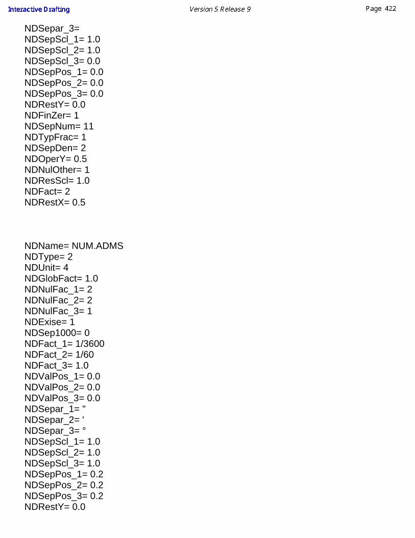
NDSepar_3= NDSepScl_1= 1.0NDSepScl_2= 1.0NDSepScl_3= 0.0NDSepPos_1= 0.0NDSepPos_2= 0.0NDSepPos_3= 0.0NDRestY= 0.0NDFinZer= 1NDSepNum= 11NDTypFrac= 1NDSepDen= 2NDOperY= 0.5NDNulOther= 1NDResScl= 1.0NDFact= 2NDRestX= 0.5
NDName= NUM.ADMSNDType= 2NDUnit= 4NDGlobFact= 1.0NDNulFac_1= 2NDNulFac_2= 2NDNulFac_3= 1NDExise= 1NDSep1000= 0NDFact_1= 1/3600NDFact_2= 1/60NDFact_3= 1.0NDValPos_1= 0.0NDValPos_2= 0.0NDValPos_3= 0.0NDSepar_1= "NDSepar_2= 'NDSepar_3= °NDSepScl_1= 1.0NDSepScl_2= 1.0NDSepScl_3= 1.0NDSepPos_1= 0.2NDSepPos_2= 0.2NDSepPos_3= 0.2NDRestY= 0.0
NDFinZer= 1NDSepNum= 11NDTypFrac= 2NDSepDen= 2NDOperY= 0.5NDNulOther= 1NDResScl= 1.0NDFact= 3NDRestX= 0.5
NDName= NUM,ADMSNDType= 2NDUnit= 4NDGlobFact= 1.0NDNulFac_1= 1NDNulFac_2= 2NDNulFac_3= 1NDExise= 1NDSep1000= 0NDFact_1= 1/3600NDFact_2= 1/60NDFact_3= 1.0NDValPos_1= 0.0NDValPos_2= 0.0NDValPos_3= 0.0NDSepar_1= "NDSepar_2= 'NDSepar_3= °NDSepScl_1= 1.0NDSepScl_2= 1.0NDSepScl_3= 1.0NDSepPos_1= 0.2NDSepPos_2= 0.2NDSepPos_3= 0.2NDRestY= 0.0NDFinZer= 1NDSepNum= 6NDTypFrac= 2NDSepDen= 2NDOperY= 0.5NDNulOther= 1NDResScl= 1.0NDFact= 3

NDRestX= 0.5
NDName= INC.ADMSNDType= 2NDUnit= 4NDGlobFact= 1.0NDNulFac_1= 1NDNulFac_2= 1NDNulFac_3= 1NDExise= 1NDSep1000= 0NDFact_1= 1/3600NDFact_2= 1/60NDFact_3= 1.0NDValPos_1= 0.0NDValPos_2= 0.0NDValPos_3= 0.0NDSepar_1= "NDSepar_2= 'NDSepar_3= °NDSepScl_1= 1.0NDSepScl_2= 1.0NDSepScl_3= 1.0NDSepPos_1= 0.2NDSepPos_2= 0.2NDSepPos_3= 0.2NDRestY= 0.0NDFinZer= 2NDSepNum= 11NDTypFrac= 2NDSepDen= 2NDOperY= 0.5NDNulOther= 2NDResScl= 1.0NDFact= 3NDRestX= 0.5
NDName= NUM.ARADNDType= 2NDUnit= 3NDGlobFact= 1.0

NDNulFac_1= 2NDNulFac_2= 2NDNulFac_3= 1NDExise= 1NDSep1000= 0NDFact_1= 1.0NDFact_2= 0.0NDFact_3= 0.0NDValPos_1= 0.0NDValPos_2= 0.0NDValPos_3= 0.0NDSepar_1= NDSepar_2= NDSepar_3= NDSepScl_1= 1.0NDSepScl_2= 0.0NDSepScl_3= 0.0NDSepPos_1= 0.0NDSepPos_2= 0.0NDSepPos_3= 0.0NDRestY= 0.0NDFinZer= 1NDSepNum= 11NDTypFrac= 2NDSepDen= 2NDOperY= 0.5NDNulOther= 1NDResScl= 1.0NDFact= 1NDRestX= 0.5
NDName= ANGLEDECNDType= 2NDUnit= 4NDGlobFact= 1.0NDNulFac_1= 2NDNulFac_2= 2NDNulFac_3= 1NDExise= 1NDSep1000= 0NDFact_1= 1.0NDFact_2= 0.0NDFact_3= 0.0

NDValPos_1= 0.0NDValPos_2= 0.0NDValPos_3= 0.0NDSepar_1= °NDSepar_2= NDSepar_3= NDSepScl_1= 1.0NDSepScl_2= 0.0NDSepScl_3= 0.0NDSepPos_1= 0.0NDSepPos_2= 0.0NDSepPos_3= 0.0NDRestY= 0.0NDFinZer= 1NDSepNum= 11NDTypFrac= 2NDSepDen= 2NDOperY= 0.5NDNulOther= 1NDResScl= 1.0NDFact= 1NDRestX= 0.5
NDName= ANGLEDMSNDType= 2NDUnit= 4NDGlobFact= 1.0NDNulFac_1= 2NDNulFac_2= 2NDNulFac_3= 1NDExise= 1NDSep1000= 0NDFact_1= 1/3600NDFact_2= 1/60NDFact_3= 1.0NDValPos_1= 0.0NDValPos_2= 0.0NDValPos_3= 0.0NDSepar_1= "NDSepar_2= 'NDSepar_3= °NDSepScl_1= 1.0NDSepScl_2= 1.0
NDSepScl_3= 1.0NDSepPos_1= 0.0NDSepPos_2= 0.0NDSepPos_3= 0.0NDRestY= 0.0NDFinZer= 1NDSepNum= 11NDTypFrac= 2NDSepDen= 2NDOperY= 0.5NDNulOther= 1NDResScl= 1.0NDFact= 3NDRestX= 0.5

Workbench DescriptionThis section contains the list of the icons and menus which are specific to InteractiveDrafting workbench.You may read these pages whenever you need to know greater details on thesecommands documented in other parts of the guide.
Command BoardMenu BarToolbars

Command (and Option) BoardGeneral
Grid Analysis Display Mode
Snap to Point Show Constraints
Detected Constraints Filter Generated Elements
Projected/Forced/True Length Dimension
Drawing
Sheets
New Sheet
New View
2D Component
Re-using 2D Component
Views
Multiple View Projection Define the view plane
Dimensioning
Dimensions Extension Line Interruption TolerancingDimensions Create Interruption
Datum Feature
Cumulated Dimensions Remove Interruption
Geometrical Tolerances
Stacked Dimensions Remove all Interruptions
Length/Distance Dimensions
Angle Dimensions
Radius Dimensions

Diameter Dimensions
Chamfer Dimensions
Thread Dimension
Coordinate Dimensions
Hole Dimension Table
Annotations
Texts Symbols
Text
Roughness Symbol
Text with Leader
Welding Symbol
Text Replicate
Geometry Weld
Balloon
Datum Target
Table
Dress-up Elements
Axis and Threads
Center Line (No Reference)
Thread (No Reference)
Center Line (Reference)
Thread (Reference)
Axis Line Axis Line and Center Line
2D Component
Re-use a component from a catalog
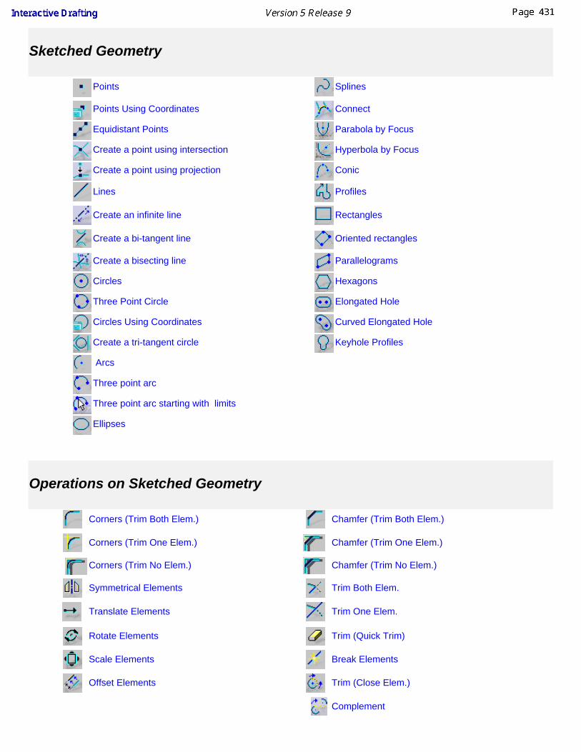
Sketched Geometry
Points
Splines
Points Using Coordinates Connect
Equidistant Points Parabola by Focus
Create a point using intersection Hyperbola by Focus
Create a point using projection Conic
Lines Profiles
Create an infinite line
Rectangles
Create a bi-tangent line Oriented rectangles
Create a bisecting line Parallelograms
Circles Hexagons
Three Point Circle Elongated Hole
Circles Using Coordinates Curved Elongated Hole
Create a tri-tangent circle Keyhole Profiles
Arcs
Three point arc
Three point arc starting with limits
Ellipses
Operations on Sketched Geometry
Corners (Trim Both Elem.)
Chamfer (Trim Both Elem.)
Corners (Trim One Elem.) Chamfer (Trim One Elem.)
Corners (Trim No Elem.) Chamfer (Trim No Elem.)
Symmetrical Elements
Trim Both Elem.
Translate Elements
Trim One Elem.
Rotate Elements
Trim (Quick Trim)
Scale Elements
Break Elements
Offset Elements
Trim (Close Elem.)
Complement

Constraints
Constraints (Dialog Box) Contact Constraint
Graphic Properties
line colorline typeline weight
Copy Object Format
Pattern
Dimension Properties
Line Type
one part dimension
Tolerance descriptionUnitPrecision
two part dimension
two part leader
Text Properties
Font NameFont Size

Bold Superscript
Italic
Subscript
Underline Left Justification
Strike-thru Center Justification
Over-line Right Justification
Anchor point Frame
Insert Symbol
Style
Style

Interactive Drafting Menu BarIn this chapter we will describe the various menus, submenus and items specific to theInteractive Drafting workbench.
Menu Purpose
FileSave the document to the required format,customize the sheet and print it aftermodifying the settings if needed.
Edit Manipulate selected objectsInsert Insert various types of elements
Tools Set user preferences

FileFor all File menu items, see the Infrastructure User's Guide
I

EditAlso refer to the Infrastructure User's Guide.
For... See...
Background Creating a Frame Title Block
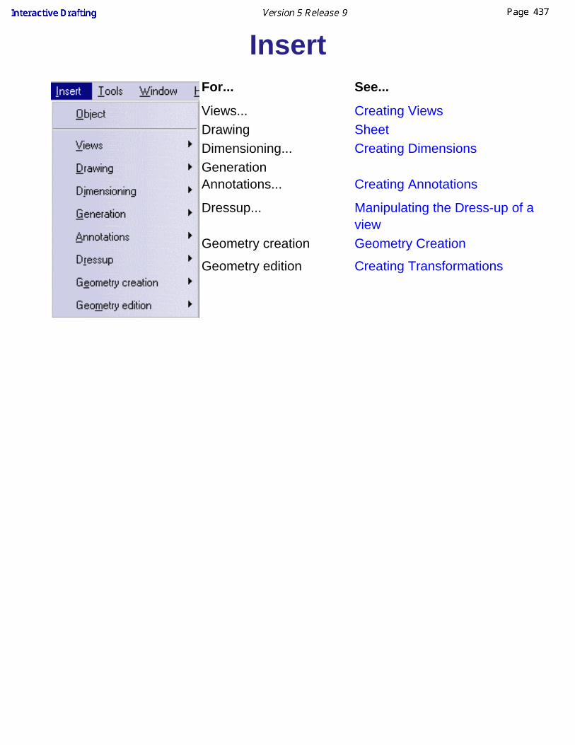
InsertFor... See...
Views... Creating ViewsDrawing SheetDimensioning... Creating DimensionsGenerationAnnotations... Creating Annotations
Dressup... Manipulating the Dress-up of aview
Geometry creation Geometry Creation
Geometry edition Creating Transformations

ToolsAlso refer to the Infrastructure User's Guide.
For... See...
Options Customization
Positioning Lining up Dimensions
Reset All Defaults Setting as Default Properties
Visualization Filters Infrastructure User's Guide

Interactive Drafting ToolbarsThis section describes the various icons of the Interactive Drafting workbench. Thetoolbars are located on each side of the workbench in the default set-up.
Toolbar PurposeGeometry Creation Create geometryTransformations Transfom existing 2D elementsAnnotations Add annotations to existing views by creating themDressup Add Dressup elements on the drawing
Dimensions Create all types of dimensions needed for yourdrawing
Constraints Add constraints to elements on the drawingViews Add new views to the drawingProperties Dimensions Properties Modify the dimensions propertiesText Properties Modify the text propertiesGraphic Properties Modify the graphic properties of all kind of featuresTools Activate display and positionning toolsUse Defaults Reset the default parameters

Geometry Creation
See Points See Three Point Arc
See Points Using Coordinates See Profiles
See Equidistant Points See Curves
See Lines See Rectangles
See Circles See Oriented rectangles
See Three Point Circle See Parallelograms
See Circles Using Coordinates See Hexagons
See Ellipses See Oblong Profiles
See Arcs See Oblong Arcs
See Keyhole Profiles

Transformations
See Modifying a Corner See Creating SymmetricalElements
See Modifying aChamfer See Translating Elements
See Trimming Elements See Rotating Elements
See Breaking Elements See Scaling Elements
See Offsetting Elements
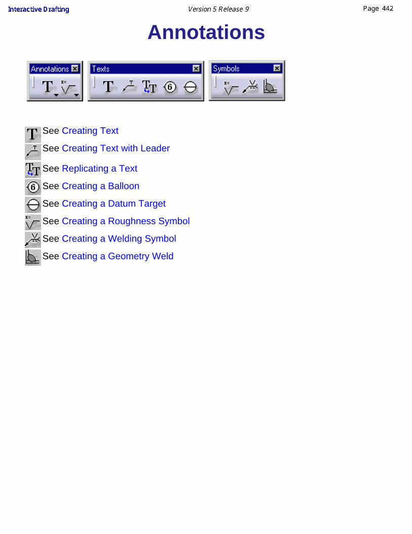
Annotations
See Creating Text
See Creating Text with Leader
See Replicating a Text
See Creating a Balloon
See Creating a Datum Target
See Creating a Roughness Symbol
See Creating a Welding Symbol
See Creating a Geometry Weld

Dressup
See Creating a Center Line and Modifying a Center line
See Creating a Center Line and Modifying a Center line
See Creating a Thread
See Creating a Thread
See Creating an Axis Line
See Creating the Area-Fill
See Creating an Arrow
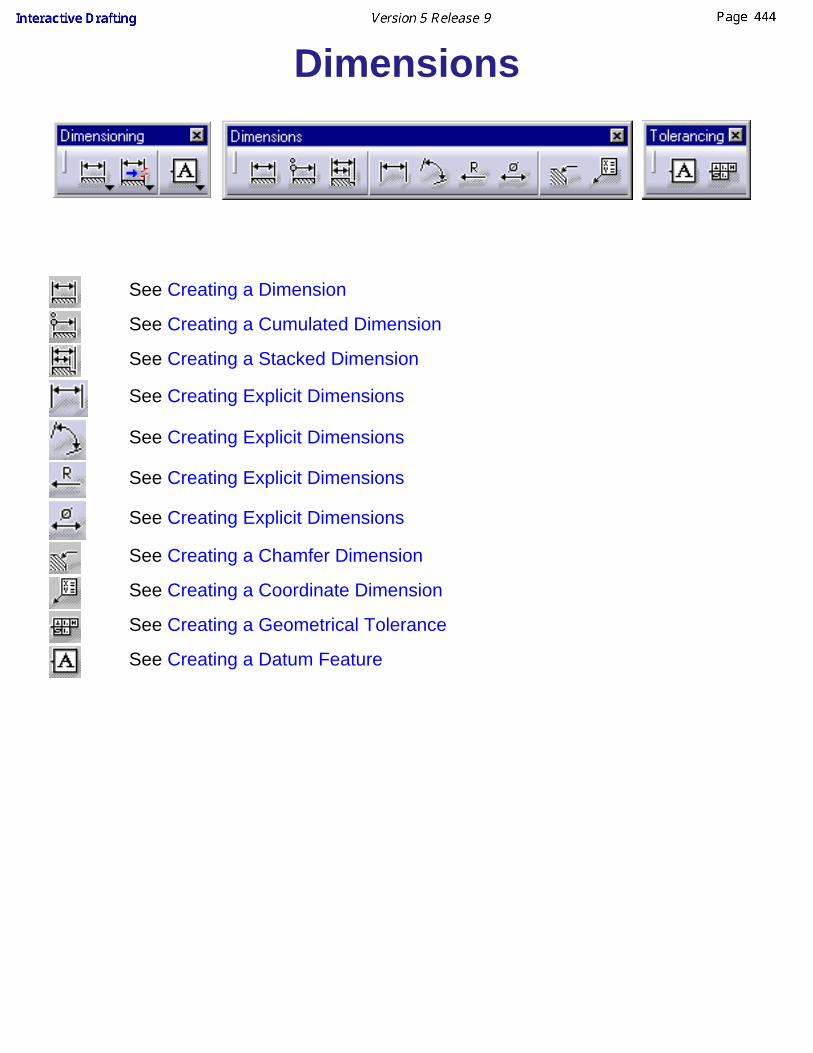
Dimensions
See Creating a Dimension
See Creating a Cumulated Dimension
See Creating a Stacked Dimension
See Creating Explicit Dimensions
See Creating Explicit Dimensions
See Creating Explicit Dimensions
See Creating Explicit Dimensions
See Creating a Chamfer Dimension
See Creating a Coordinate Dimension
See Creating a Geometrical Tolerance
See Creating a Datum Feature

Text Properties
See Setting Text Properties

Graphic Properties
See Displaying and Editing Dress-Up Element Properties

Dimension Properties
See Before You Begin (Dimensions)

Tools
See Using Tools
See Using Tools
See Constraints
See Constraints
See Using Tools
Use Defaults
Resets to default parameters

Views
See Creating Views

Customizing for Interactive DraftingThis section explains how to customize settings for Interactive Drafting.
General settingsSet general settings to be used in the Interactive Drafting workbench.
Dimension creationCustomize given options when creating or re-positioning dimensions.
Geometry and dimension generationCustomize given options for controlling geometry and dimensiongeneration whenever you need to update sheets.
Geometry creationCustomize given options when creating 2D geometry, either or not usingautodetection (or SmartPick), or still adding constraints to this geometry.
View and sheet layoutCustomize given options when creating views or when adding sheets.
ManipulatorsVisualize given manipulators whenever creating or modifying dimensions.
AnnotationsCustomize given options when creating annotations.
Administration SettingsCustomize settings for the management of drawings.
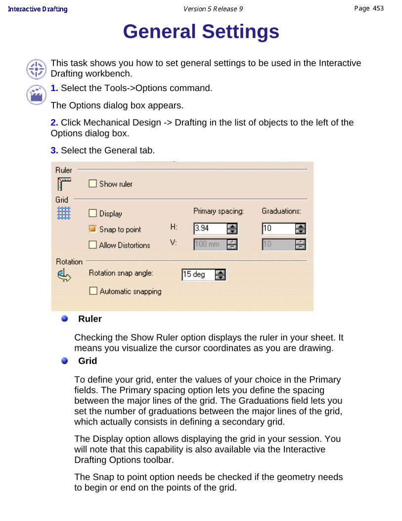
General SettingsThis task shows you how to set general settings to be used in the InteractiveDrafting workbench.1. Select the Tools->Options command.
The Options dialog box appears.
2. Click Mechanical Design -> Drafting in the list of objects to the left of theOptions dialog box.
3. Select the General tab.
Ruler
Checking the Show Ruler option displays the ruler in your sheet. Itmeans you visualize the cursor coordinates as you are drawing. Grid
To define your grid, enter the values of your choice in the Primary fields. The Primary spacing option lets you define the spacingbetween the major lines of the grid. The Graduations field lets youset the number of graduations between the major lines of the grid,which actually consists in defining a secondary grid.
The Display option allows displaying the grid in your session. Youwill note that this capability is also available via the InteractiveDrafting Options toolbar.
The Snap to point option needs be checked if the geometry needsto begin or end on the points of the grid.

The Allow Distortions option allows applying different graduationsand spacing between H and V.Rotation
The Rotation Snap Angle option allows snapping with a given anglefor rotating elements. This option is used to rotate text elements(text, frame, or leader). In other words, it defines the snapping valueused when rotating an element using the Select or Rotatecommands.
The Automatic Snapping option allows to automate this option.
Colors
You can customize given options for modifying the drawingbackground color.
As shown below, you can customize the color type.
This is what you get if you do as detailed above:
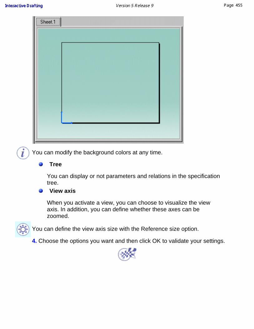
You can modify the background colors at any time.
Tree
You can display or not parameters and relations in the specificationtree.View axis
When you activate a view, you can choose to visualize the viewaxis. In addition, you can define whether these axes can bezoomed.
You can define the view axis size with the Reference size option.
4. Choose the options you want and then click OK to validate your settings.
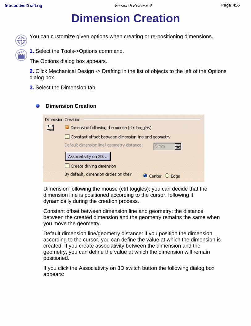
Dimension CreationYou can customize given options when creating or re-positioning dimensions.
1. Select the Tools->Options command.
The Options dialog box appears.
2. Click Mechanical Design -> Drafting in the list of objects to the left of the Optionsdialog box.
3. Select the Dimension tab.
Dimension Creation
Dimension following the mouse (ctrl toggles): you can decide that thedimension line is positioned according to the cursor, following itdynamically during the creation process.
Constant offset between dimension line and geometry: the distancebetween the created dimension and the geometry remains the same whenyou move the geometry.
Default dimension line/geometry distance: if you position the dimensionaccording to the cursor, you can define the value at which the dimension iscreated. If you create associativity between the dimension and thegeometry, you can define the value at which the dimension will remainpositioned.
If you click the Associativity on 3D switch button the following dialog boxappears:

A link can be applied between a dimension and the 3D part. As a result,when you update the drawing, the dimension is automatically re-computed.If you do not check this option, when you perform the update, you need tore-create the dimension afterwards.Create driving dimensions: the dimension you will create will drive thegeometry.A new field appears in the toolbar during creation process, it allows you toenter the driving dimension value.
By default, dimension circles on their: the dimension you will createbetween a circle and another element will be either on the circle center oron the circle edge. Move
Activating Move only selected sub-part allows you to move only adimension sub-part (text, line, etc.).
You can activate the snapping option selecting Activate Snapping (shifttoggles). The Configure switch button allows you to choose either thedimension to be snapped on the grid or/and the dimension value to belocated at its default position between symbols (it will work only if thecursor is between the symbols).
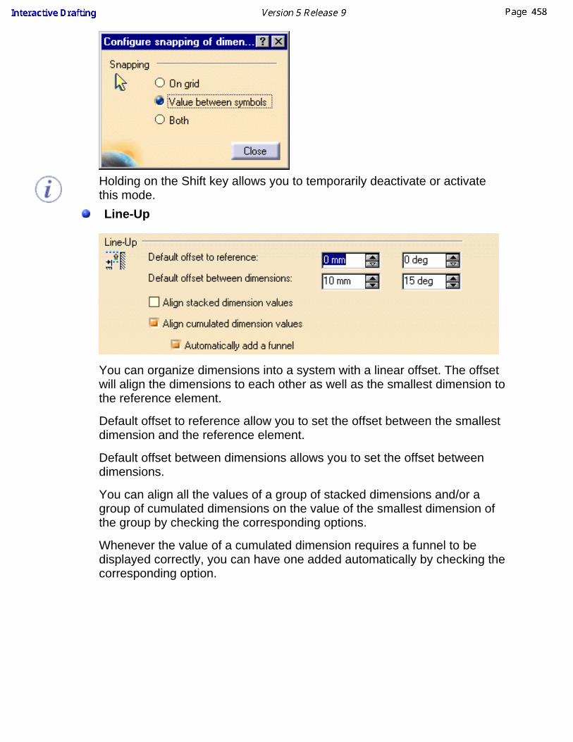
Holding on the Shift key allows you to temporarily deactivate or activatethis mode.Line-Up
You can organize dimensions into a system with a linear offset. The offsetwill align the dimensions to each other as well as the smallest dimension tothe reference element.
Default offset to reference allow you to set the offset between the smallestdimension and the reference element.
Default offset between dimensions allows you to set the offset betweendimensions.
You can align all the values of a group of stacked dimensions and/or agroup of cumulated dimensions on the value of the smallest dimension ofthe group by checking the corresponding options.
Whenever the value of a cumulated dimension requires a funnel to bedisplayed correctly, you can have one added automatically by checking thecorresponding option.

Analysis Display Mode
Colors can be customized with the Activate analysis display mode option.If you activate this mode, it allows you to assign the desired color(s) to thedesired dimension types by clicking the Types and colors switch button.
You will then be able to visualizing the colors assigned to the differenttypes of dimensions.
4. Choose the options you want and then click OK to validate your settings.
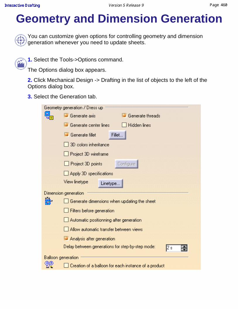
Geometry and Dimension GenerationYou can customize given options for controlling geometry and dimensiongeneration whenever you need to update sheets.
1. Select the Tools->Options command.
The Options dialog box appears.
2. Click Mechanical Design -> Drafting in the list of objects to the left of theOptions dialog box.
3. Select the Generation tab.
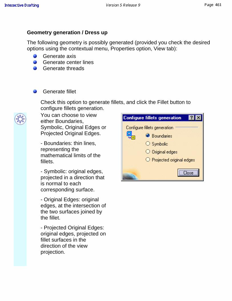
Geometry generation / Dress up
The following geometry is possibly generated (provided you check the desiredoptions using the contextual menu, Properties option, View tab):
Generate axisGenerate center linesGenerate threads
Generate fillet
Check this option to generate fillets, and click the Fillet button toconfigure fillets generation. You can choose to vieweither Boundaries,Symbolic, Original Edges orProjected Original Edges.
- Boundaries: thin lines,representing themathematical limits of thefillets.
- Symbolic: original edges,projected in a direction thatis normal to eachcorresponding surface.
- Original Edges: originaledges, at the intersection ofthe two surfaces joined bythe fillet.
- Projected Original Edges:original edges, projected onfillet surfaces in thedirection of the viewprojection.

Hidden lines3D colors inheritance: the colors of a part can be automatically generatedonto the views. Be careful: if the color of the part is white and the 3D colors inheritanceoption is checked, the generated views will be white and will therefore notbe properly displayed.Project 3D wireframeBoth the wireframe and the geometry can be visualized on generatedviews.Project 3D pointsCheck this option to projectpoints from 3D (no constructionelement).Click the Configure button toselect the type of pointsvisualized in the projecteddrawing:
You can keep the symbol from3D, or choose a new symbol.
Apply 3D specificationIn an assembly, you can define that given parts will or will not besectioned into section views or breakout views (Generative Draftingworkbench). For this, you select one view, then the Edit -> Propertiescommand from the menu bar from the Assembly Design workbench(Mechanical tab, Drafting properties options) and either activate orde-activate the Not cut in section views options.

Linetype buttonClick the Linetype button toconfigure linetypes for specifictypes of views. In the Linetypefor some views dialog box,select the line type you need foreach type of view and clickClose.
Dimension generation
The generated dimensions are positioned according to the views mostrepresentative. In other words, a dimension will appear on a view so that thisdimension needs not be also created on another view.
The dimensions are generated on the views on the condition the settings werepreviously switched to the dimension generation option.
If you check the Generate dimensions when updating the sheet option, thisoption makes the application automatically generate dimensions each time youupdate the sheet.
Balloon generation
If you select Creation of a balloon for each instance of a product, a balloon will begenerated for each instance of a component: therefore, if a component is usedtwo times within a product, then the balloon will be generated twice.
If you leave this box unselected, a single balloon will be generated for allinstances of the same component, when a component is used several timeswithin a part or product.
4. Choose the options you want and then click OK to validate your settings.

Geometry CreationYou can customize given options when creating 2D geometry, either or notusing autodetection (or SmartPick), or still adding constraints to this geometry.1. Select the Tools->Options command.
The Options dialog box appears.
2. Click Mechanical Design -> Drafting in the list of objects to the left of theOptions dialog box.
3. Select the Geometry tab.

Geometry
You can decide that you want to create circle and ellipses centersand that you want to be able to drag elements, end points included.Constraints creation
You can create or not the geometrical or dimensional constraintsdetected by the SmartPick tool.
If all of the detection options are unchecked, the Create detectedconstraints option is not available.
SmartPick (switch button)As you create more and more elements, SmartPick detects multipledirections and positions, and more and more relationships withexisting elements. This may lead to confusion due to the rapidhighlighting of several different detection possibilities as you pointthe cursor at different elements in rapid succession. Consequently,you can decide to filter out undesired detections. This task showshow to do so:
The SmartPick category provides these options:Support lines and circlesAlignmentParallelism, perpendicularity and tangencyHorizontality and verticality
Uncheck the elements you do not wish to detect when sketching.
Disabling SmartPick completely is particularly useful when yourscreen is full of elements: in this case, it may be a good idea todisable SmartPick to concentrate only on the geometry.

Constraints Visualization
1. Check the Visualize constraints option to visualize the logicalconstraints specific to the elements.2. Modify the reference size, if needed.3. Modify the constraints color using the combo, if needed.Note that if the Visualize constraints option is unchecked, theelements are not available.
Constraints types (switch button)
You can define which types of constraints you will visualize as youcreate the geometry.
Colors
Two types of colors may be applied to sketched elements. Thesetwo types of colors correspond to colors illustrating:Graphical properties: Colors that can be modified. These colorscan therefore be modified using the Tools->Options dialog box.
ORConstraint diagnostics: Colors that represent constraintdiagnostics are colors that are imposed to elements whatever the

graphical properties previously assigned to these elements and inaccordance with given diagnostics. As a result, as soon as thediagnostic is solved, the element is assigned the color as defined inthe Tools->Options dialog box.
You can assign default colors to all the elements.
If you click the Visualization of diagnostic switch button, thefollowing dialog box appears:
Over-constrained elements: the dimensioning scheme isover-constrained: too many dimensions were applied to thegeometry.
Inconsistent elements: At least one dimension value needs to bechanged. This is also the case when elements areunder-constrained and the system proposes defaults that do notlead to a solution.
Not-changed elements: Some geometrical elements areover-defined or not-consistent. As a result, geometry that depend(s)on the problematic area will not be recalculated.
Iso-constrained elements: All the relevant dimensions are satisfied.The geometry is fixed and cannot be moved from its geometricalsupport.
If you click the Other color of the elements switch button, thefollowing dialog box appears:

Isolated elements: use-edge that no more depend on the 3D.
Protected elements: non-modifiable elements.
Construction elements: A construction element is an element that isinternal to, and only visualized by, the sketch. This element is usedas positioning reference. It is not used for creating solid primitives.
SmartPick: colors used for SmartPick assistant elements andsymbols.
4. Choose the options you want and then click OK to validate your settings.

View and Sheet LayoutYou can customize given options when creating views or when adding sheets.
1. Select the Tools->Options command.
The Options dialog box appears.
2. Click Mechanical Design -> Drafting in the list of objects to the left of theOptions dialog box.
3. Select the Layout tab. It contains the following sets of options:
View creation
When creating a view, you can define that you want or not the viewname, scaling factor or frame to appear, and that you want brokenand breakout specifications to be reproduced.
You can decide if the auxiliary view will be oriented according to theprofile. In this case, if the reference view has an orientation angleequal to 45°, then auxiliary and section view you will create will havethe same orientation angle.
You can also get a quick preview of the 3D document whengenerating views.New sheet
You can define that when creating a new sheet, you want thesource sheet to be the first or one sheet from another drawing.Background view
You can specify the path to the directory containing frame and titleblock.Section/Projection Callout
You can choose the callout elements size not to be dependant onthe view scale. For this before callout creation check this option.
4. Choose the options you want and then click OK to validate your settings.

ManipulatorsYou can decide that you will visualize given manipulators whenever creating ormodifying dimensions.1. Select the Tools->Options command.
The Options dialog box appears.
2. Click Mechanical Design -> Drafting in the list of objects to the left of theOptions dialog box.
3. Select the Manipulators tab.

Manipulators
The settings below can be used for any type of manipulators (texts,leaders, center lines, dimensions and so forth).
You can make manipulators zoomable and, if needed, modify the sizeof the manipulators.
The size of the manipulators is a reference size which corresponds,for example, in the case of texts, to the diameter of the rotationmanipulators.
Dimension Manipulators
You will define which manipulators you will visualize and thereforeuse when creating and/or modifying dimensions:

Modify overrunIf you drag select one overrun manipulator, both overrunextension lines are modified. To modify only the selectedoverrun extension line, use the Ctrl key. You can alsodouble-click on the manipulator and enter the new value in thedialog box that appears.
1.
Modify blankingIf you drag select one blanking manipulator, both blanking aremodified. To modify only the selected blanking, use the Ctrlkey. You can also double-click on the manipulator and enterthe new value in the dialog box that appears.
2.
Insert text before Allows inserting a text before, without using the Propertiesdialog box. For this, you will click on the manipulator and enterthe new text in the dialog box that appears.
3.
Insert text afterAllows inserting a text after, without using the Properties dialogbox. For this, you will click on the manipulator and enter thenew text in the dialog box that appears.
4.
Move value Allows moving the dimension value and only it.
5.
Move dimension line Allows moving the dimension line and only it by dragging to thenew location.
6.
Move dimension line secondary partAllows moving the dimension line secondary part and only it bydragging to the new location.
7.
4. Choose the options you want and then click OK to validate your settings.

AnnotationsYou can customize given options when creating annotations.
1. Select the Tools->Options command.
The Options dialog box appears.
2. Click Mechanical Design -> Drafting in the list of objects to the left of theOptions dialog box.
3. Select the Annotation tab. It contains the following sets of options:
Annotation CreationIf you check one of the element in this option, the text or the leader (forText with leader or Geometrical tolerance) will be snapped.MoveYou can activate the snapping option selecting Activate Snapping (shifttoggles). The Configure switch button allows you to choose either theannotation to be snapped on the grid or according to the orientation, orboth.

Administration SettingsYou can customize settings for the management of drawings.
1. Select the Tools->Options command.
The Options dialog box appears.
2. Click Mechanical Design -> Drafting in the list of objects to the left of theOptions dialog box.
3. Select the Administration tab. It contains the following sets of options:
Prevent File>NewCheck this box to make it impossible to create drawings using the File ->New command. All drawings will be created using the File -> New From...command instead.Lock "Only User Default" StyleCheck this box to make it compulsory to use Only User Defaults (i.e.,user-defined values set as default). The Styles drop-down list will be setto Only User Defaults and will be inactive so that CATIA Defaults or UserDefaults cannot be selected.Prevent "Set As Default" and "Reset All Defaults"Check this box to use the current defaults and to make it impossible tocreate, change and reset user defaults (i.e. user-defined values). Thisdisables the Set as Default and the Reset All Defaults commands. Prevent switch of standardCheck this box to make it impossible to change standards, i.e. to use astandard other than the one currently defined in the Page Setup dialogbox.

Prevent update of standardCheck this box to make it impossible to update standards for the currentdocument in the Page Setup dialog box.Prevent background view accessCheck this box to make it impossible to access the background view.
4. Choose the options you want and then click OK to validate your settings.

GlossaryA
absolute position A sheet coordinates.
active viewA view in which all the modifications will be performed. Forinstance, all the 2D geometry and dressup elements that will beadded to the draft views to be created.
angle dimension A dimension applied to one or two linear elements or to circularelements.
area fill A closed area on which you will then apply graphical dressupelement called hatching pattern.
Bbackground sheet A sheet dedicated to frames and titlteblocks.
blanking A blank added between the dimensioned element on the viewand one extremity on the extension line.
Cchained dimension A dimension presentation mode made of a system.
chamfer A bevelled corner between any types of curves: lines, splines,arcs and so forth.
chamfer dimension A dimension applied to a chamfer.
corner An arc tangent between lines, arcs, circles and any types ofcurves (consecutive or that intersect).
Ddatum feature An element defining a contacting surface on a part.
datum target An element defining a contacting surface on a part andrepresented by spherical or pointed locating pins.
detail sheet A sheet that is used as an intermediate catalog for positioning2D geometry elements that will be instantiated afterwards.
diameter dimension A dimension representing either a radius or a diameter.distance dimension A dimension representing the dimension between two elements
be they linear or circular type.
ditto An instanciation of a 2D element that is stored on a detail sheet.Also called 2D component.
document A common unit of data (typically a file) used in user tasks andexchanged between users. When saved on disk, a document isgiven a unique filename by which it can be retrieved.
drawing The root feature. Sheets are aggregated in the drawing. Viewsare aggregated in the sheets.
drawing repository A drawing document containing 2D re-usable components.dress-up A graphical attribute of a 2D element.
Ffunnel A representation of the dimensions which allows inserting the
dimension value between the dimension symbols.
Oobject In the Drafting workbench, there are two kinds of object:
activated and selected. The view frame of an activated object isdisplayed in red.
overrun A part of a dimension corresponding to the extended extensionline.
Ppart A 3D entity obtained by combining different features in the Part
Design workbench.
Rradius dimension A dimension applied to a circle, semi-circle or arc of a circle.roughness symbol A symbol that is used for defining a surface.
Ssheet A set of views. Several sheets may be created in the Drafting
workbench.standard An international convention that is supported in the Drafting
workbench: ANSI, ISO and JIS.
Ttemplate In the Drafting workbench, an object that is included in the
document (for example, the title block).
third angle A projection method that allows projecting views from a partaccording to ISO/ANSI international standards.
title block A frame which contains the title block.
Vview frame A square or rectangular frame that contains the geometry and
dimensions of the view.
Index
Numerics2D component
add a leader
automate creation
create
explode
modify annotation orientation
modify text
positionning
re-use a 2D component 2D component instance
edit properties 2D geometry feature
edit properties
Aangle
dimensions annotation
edit properties
modify annotation positioning arc
create area fill

create arrow
create associative thread dimensions
create attribute
replicate attribute attribute link
add attribute link to text
autodetection axis lines
create
create several axis lines
Bballoon
associative balloons
create
modify bisecting line
create bitangent line
create
Ccatalog
component
create center lines
create center lines (no reference)
create
modify center lines (reference)
create
modify chamfer
dimensions circle
create circle using coordinates
create command
Copy
Paste component
catalog conic
create connect
elements constraints
constraints between 2D and generated elements
constraints via smartpick
create constraints between 2D and generated elements
dimension constraints
geometrical constraints

setting relations between dimensional constraints coordinate dimensions
create Copy
command create
2D component
arc
area fill
arrow
associated text
associative balloons on views from products
axis lines
balloon
bisecting line
bitangent line
catalog
center lines
center lines (no reference)
center lines (reference)
circle
circle using coordinates
conic
constraints between 2D and generated elements
constraints via smartpick
coordinate dimensions
cumulated dimensions
cylindrical elongated hole

datum feature
datum target
dimension contraints
dimensions
ellipse
elongated hole
equidistant point
explicit dimensions
frame title block
geometrical constraints
geometrical tolerance
geometry weld
half dimension
hexagon
hyperbola by focus
infinite line
keyhole profile
line
multiple view projection
oriented rectangle
parabola by focus
parallelogram
pofile
point
point using coordinates
point using intersection
point using projection

points coordinates table
rectangle
roughness symbol
several axis lines
spline
stacked dimensions
table
text with a leader
thread
thread (reference)
three point arc
three point circle
tritangent circle
view
view using folding lines
welding symbol creating
free text cumulated dimensions
create cylindrical elongated hole
create
Ddatum
datum target
feature
datum feature
create datum target
create default properties
set dimension contraints
create dimension line location
modify dimension type
modify dimensions
angle
associative thread dimensions
chamfer
create
dimension extension line properties
dimension line properties
dimension text properties
dimension tolerance properties
edit dimension value properties
explicit dimensions
holes dimensions table
line up
modify text before/after
modify value text position
search dimension status
setting relations between dimensional constraints

stacked dimensions dimensions blanking
modify dimensions overrun
modify
Eelements
connect ellipse
create elongated hole
create equidistant point
create extension line
interrupt
FFrame
Text frame title block
create free text
creating

Ggeometrical constraints
create geometrical tolerance
create
modify geometry weld
create graphic
edit properties graphical properties
copy
Hhalf dimension
create hexagon
create holes dimensions table
generate hyperbola by focus
create
Iinfinite line
create

Kkeyhole profile
create
Lleader
add a leader to existing text line
create line up
dimensions
Mmodify
annotation positioning
balloon
center lines (no reference)
center lines (reference)
datum feature
datum target
dimension line location
dimension type
dimensions blanking
dimensions overrun

geometrical tolerance multiple view projection
create
Ooriented rectangle
create
Pparabola by focus
create parallelogram
create Paste
command pofile
create point
create point using coordinates
create point using intersection
create point using projection
create points
create points coordinates table

Print print
document after modifying current display settings
print using clipping operator print using clipping operator
print properties
2D component instance properties
2D geometry feature properties
annotation font properties
dimension extension line properties
dimension line properties
dimension text properties
dimension tolerance properties
dimension value properties
element graphic properties
text
text properties
Rrectangle
create roughness symbol
create
symbol definition

Ssearch
advanced search sheet
define
delete
modify
smartpick spline
create standards
managing standards
Ttable
create
create points coordinates table tex
associated text Text
Frame text
add attribute link to text
edit properties
find and replace
free text
making an existing text associative

properties
replicate text
text properties
text with a leader thread
create thread (reference)
create three point arc
create three point circle
create tools
use tritangent circle
create
Vview
create view plane
define view using folding lines
create views
reframe a view

Wwelding symbol
create
symbol definition