Interactive Computer Graphics CS 537 - Drexel CCIdavid/Classes/ICG/Lectures_new/L-1... ·...
45
Interactive Computer Graphics CS 537 Prof. David E. Breen Department of Computer Science 1
Transcript of Interactive Computer Graphics CS 537 - Drexel CCIdavid/Classes/ICG/Lectures_new/L-1... ·...

Interactive Computer Graphics CS 537
Prof. David E. Breen Department of Computer Science
1

2Angel and Shreiner: Interactive Computer Graphics 6E © Addison-Wesley 2012
Objectives
• Introduction to Interactive Computer Graphics - Software - Hardware - Applications
• Top-down approach • Shader-Based OpenGL compatible with
- OpenGL 3.1 (and later) - Open GL ES 2.0 - webGL
3Angel and Shreiner: Interactive Computer Graphics 6E © Addison-Wesley 2012
Credits
• Course structure based on Ed Angel and Dave Shreiner, Interactive Computer Graphics, A Top-down Approach with OpenGL (Sixth Edition), Addison-Wesley, 2012
• Slides based on lectures for CS/EECE 412 Computer Graphics at the University of New Mexico by Prof. Edward Angel
4Angel and Shreiner: Interactive Computer Graphics 6E © Addison-Wesley 2012
Prerequisites
• Good programming skills - High-level and low-level
• Unix-based software development • Basic Data Structures
- Linked lists - Arrays
• Geometry • Linear Algebra
- Vectors & matrices

5Angel and Shreiner: Interactive Computer Graphics 6E © Addison-Wesley 2012
Requirements
• Weekly Programming Projects • Summarize a research paper • Go to class web site

6Angel and Shreiner: Interactive Computer Graphics 6E © Addison-Wesley 2012
Resources
• Can run OpenGL on any system - Windows: check graphics card properties for level of OpenGL supported
- Linux - Mac: need extensions for 3.1 equivalence
• Get GLUT from web if needed - Provided on Macs - freeglut available on web
• Get GLEW from web

7Angel and Shreiner: Interactive Computer Graphics 6E © Addison-Wesley 2012
References
• www.opengl.org - Standards documents - Sample code
• The OpenGL Programmer’s Guide (the Redbook) 9th Edition
• The definitive reference • OpenGL 4.5
• OpenGL Shading Language, 3rd Edition • All Addison-Wesley Professional
8Angel and Shreiner: Interactive Computer Graphics6E © Addison-Wesley 2012
Image Formation

9Angel and Shreiner: Interactive Computer Graphics6E © Addison-Wesley 2012
Objectives
• Fundamental imaging notions • Physical basis for image formation
- Light - Color - Perception
• Synthetic camera model • Other models

10Angel and Shreiner: Interactive Computer Graphics6E © Addison-Wesley 2012
Image Formation
• In computer graphics, we form images which are generally two dimensional using a process analogous to how images are formed by physical imaging systems
- Cameras - Microscopes - Telescopes - Human visual system

11Angel and Shreiner: Interactive Computer Graphics6E © Addison-Wesley 2012
Elements of Image Formation
• Objects • Viewer • Light source(s)
• Attributes that govern how light interacts with the materials in the scene
• Note the independence of the objects, the viewer, and the light source(s)

12
Light
• Light is the part of the electromagnetic spectrum that causes a reaction in our visual systems
• Generally these are wavelengths in the range of about 350-750 nm (nanometers)
• Long wavelengths appear as reds and short wavelengths as blues

13
# Ph
oton
s
Wavelength (nm)
400 500 600 700
400 500 600 700
# Ph
oton
s
Wavelength (nm)
Violet 388-440nm Blue 440-490nm Green 490-565nm Yellow 565-590nm Orange 590-630nm Red 630-780nm
White
Less White (Gray)
Laser
# Ph
oton
s
Wavelength (nm)
400 500 600 700
Pure day light
Spectral Energy Distributions

14Angel and Shreiner: Interactive Computer Graphics6E © Addison-Wesley 2012
Luminance and Color Images
• Luminance Image - Monochromatic - Values are gray levels - Analogous to working with black and white film
or television
• Color Image - Has perceptional attributes of hue, saturation,
and lightness - Do we have to match every frequency in visible
spectrum? No!

15Angel and Shreiner: Interactive Computer Graphics6E © Addison-Wesley 2012
Three-Color Theory
• Human visual system has two types of sensors
- Rods: monochromatic, night vision - Cones
• Color sensitive • Three types of cones • Only three values (the tristimulus values) are sent to the brain
• Need only match these three values - Need only three primary colors

17Angel and Shreiner: Interactive Computer Graphics6E © Addison-Wesley 2012
Additive and Subtractive Color
• Additive color - Form a color by
adding amounts of three primaries
• CRTs, projection systems, positive film
- Primaries are Red (R), Green (G), Blue (B)

18
RGB Color Cube
• RGB used in Monitors and other light emitting devices
• TV uses YIQ encoding which is somewhat similar to RGB
http://prometheus.cecs.csulb.edu/~jewett/colors/
RGB Color Cube

19Angel and Shreiner: Interactive Computer Graphics6E © Addison-Wesley 2012
Additive and Subtractive Color
• Subtractive color - Form a color by
filtering white light with cyan (C), Magenta (M), and Yellow (Y) filters
• Light-material interactions
• Printing • Negative film
20
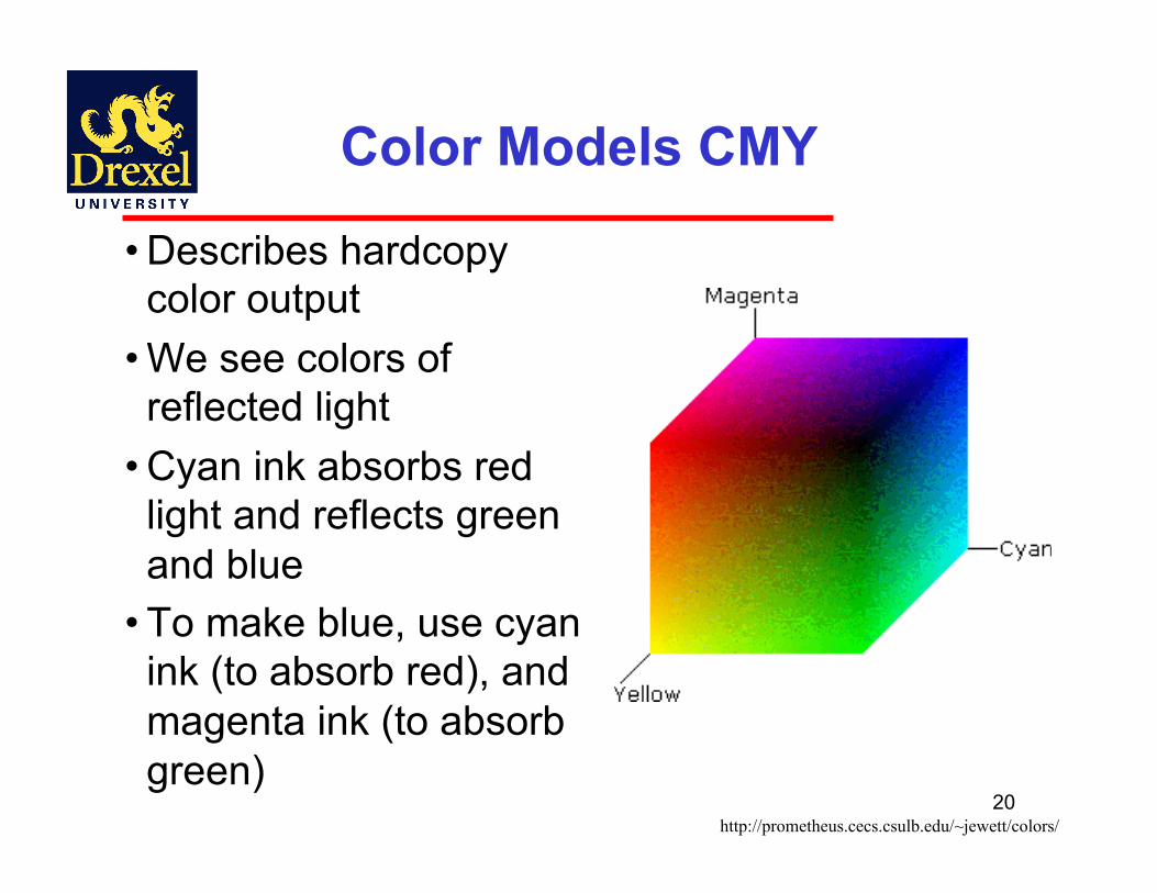
Color Models CMY
• Describes hardcopy color output
• We see colors of reflected light
• Cyan ink absorbs red light and reflects green and blue
• To make blue, use cyan ink (to absorb red), and magenta ink (to absorb green)
http://prometheus.cecs.csulb.edu/~jewett/colors/

HSB: hue, saturation, and brightness
• Also called HSV (hue saturation value)
• Hue is the actual color. Measured in degrees around the cone (red = 0 or 360 yellow = 60, green = 120, etc.).
• Saturation is the purity of the color, measured in percent from the center of the cone (0) to the surface (100). At 0% saturation, hue is meaningless.
• Brightness is measured in percent from black (0) to white (100). At 0% brightness, both hue and saturation are meaningless. 2
1

22Angel and Shreiner: Interactive Computer Graphics6E © Addison-Wesley 2012
Ray Tracing and Geometric Optics
One way to form an image is to follow rays of light from a point source finding which rays enter the lens of the camera. However, each ray of light may have multiple interactions with objects before being absorbed or going to infinity.

23Angel and Shreiner: Interactive Computer Graphics6E © Addison-Wesley 2012
Global vs Local Lighting
• Cannot compute color or shade of each object independently
- Some objects are blocked from light - Light can reflect from object to object - Some objects might be translucent

24Angel and Shreiner: Interactive Computer Graphics6E © Addison-Wesley 2012
Synthetic Camera Model
center of projection
image plane
projector
p
projection of p
• Local lighting
• Projects geometry onto image plane.
• Use local info to shade point

25Angel and Shreiner: Interactive Computer Graphics6E © Addison-Wesley 2012
Pinhole Camera
xp= -x/(z/d) yp= -y/(z/d)
Use trigonometry to find projection of point at (x,y,z)
These are equations of simple perspective
zp= d
26Angel and Shreiner: Interactive Computer Graphics6E © Addison-Wesley 2012
Advantages – Local Lighting
• Separation of objects, viewer, light sources • Two-dimensional graphics is a special case of three-dimensional graphics
• Leads to simple software API - Specify objects, lights, camera, attributes - Let implementation determine image
• Leads to fast hardware implementation • Allows for pipelined & parallel computations

27Angel and Shreiner: Interactive Computer Graphics6E © Addison-Wesley 2012
Why not ray tracing?
Ray tracing seems more physically based, so why don’t we use it to design a graphics system? • It is actually simple for simple objects, such as
polygons and quadrics with simple point sources • In principle, can produce global lighting effects
such as shadows and multiple reflections, but ray tracing is slow and not well-suited for interactive applications
• Ray tracing hardware has been developed (Pixel Machines), but has not survived in market
• Ray tracing with GPUs is close to real time

28E. Angel and D. Shreiner: Interactive Computer Graphics 6E © Addison-Wesley 2012
Models and Architectures
29E. Angel and D. Shreiner: Interactive Computer Graphics 6E © Addison-Wesley 2012
Objectives
• Learn the basic design of a graphics system
• Introduce pipeline architecture • Examine software components for an interactive graphics system

30E. Angel and D. Shreiner: Interactive Computer Graphics 6E © Addison-Wesley 2012
Image Formation Revisited
• Can we mimic the synthetic camera model to design graphics hardware & software?
• Application Programmer Interface (API) - Need only specify
• Objects • Materials • Viewer • Lights
• But how is the API implemented?
31E. Angel and D. Shreiner: Interactive Computer Graphics 6E © Addison-Wesley 2012
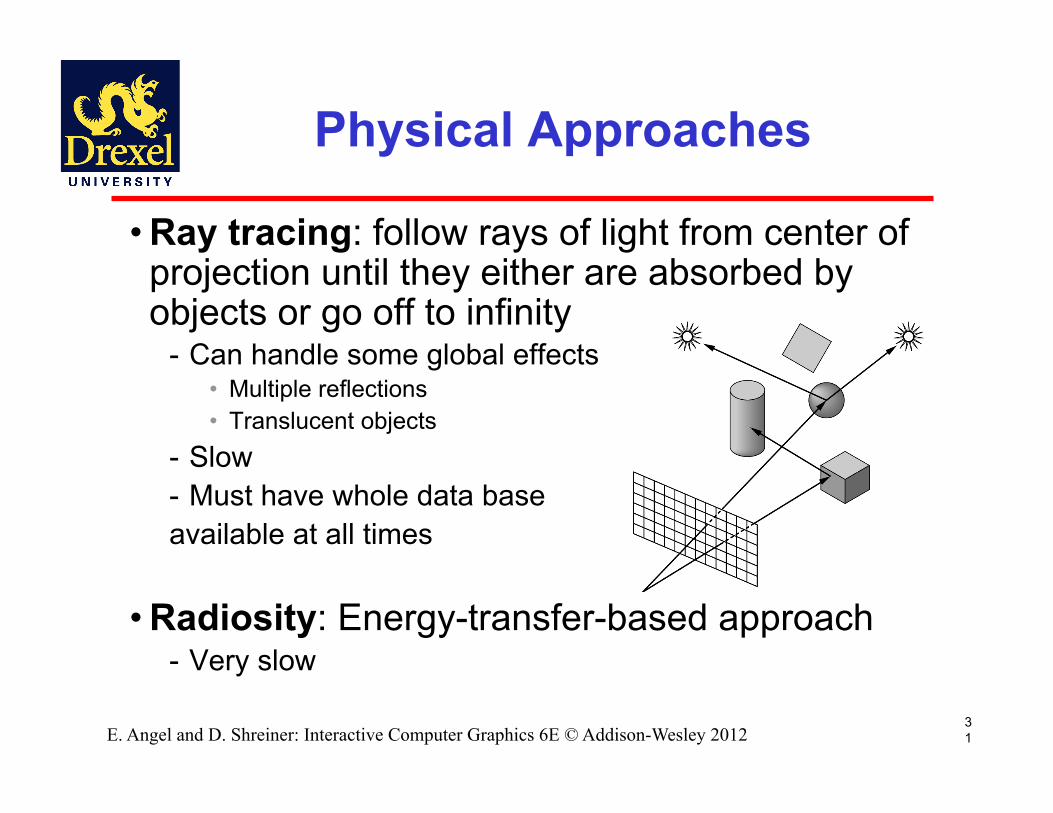
Physical Approaches
• Ray tracing: follow rays of light from center of projection until they either are absorbed by objects or go off to infinity
- Can handle some global effects • Multiple reflections • Translucent objects
- Slow - Must have whole data base available at all times
• Radiosity: Energy-transfer-based approach - Very slow

32E. Angel and D. Shreiner: Interactive Computer Graphics 6E © Addison-Wesley 2012
Practical Approach
• Process objects one at a time in the order they are generated by the application
- Can consider only local lighting • Pipeline architecture
• All steps can be implemented in hardware on the graphics card
application program
display

33E. Angel and D. Shreiner: Interactive Computer Graphics 6E © Addison-Wesley 2012
Vertex Processing
• Much of the work in the pipeline is in converting object representations from one coordinate system to another
- Object coordinates - Camera (eye) coordinates - Screen coordinates
• Every change of coordinates is equivalent to a matrix transformation
• Vertex processor also computes vertex colors

34E. Angel and D. Shreiner: Interactive Computer Graphics 6E © Addison-Wesley 2012
Projection
• Projection is the process that combines the 3D view with the 3D objects to produce the 2D image
- Perspective projections: all projectors meet at the center of projection
- Parallel projection: projectors are parallel, center of projection is replaced by a direction of projection

Planar Geometric Projections
35
• Projections onto Planes - Consider the line AB
• Perspective Projection - a single viewing location - similar to a photograph
• Parallel Projection - viewing location at - good for capturing shape
and dimensions
1994 Foley/VanDam/Finer/Huges/Phillips ICG
∞

36E. Angel and D. Shreiner: Interactive Computer Graphics 6E © Addison-Wesley 2012
Primitive Assembly
Vertices must be collected into geometric objects before clipping and rasterization can take place
- Line segments - Polygons - Curves and surfaces

37E. Angel and D. Shreiner: Interactive Computer Graphics 6E © Addison-Wesley 2012
Clipping
Just as a real camera cannot “see” the whole world, the virtual camera can only see part of the world or object space
- Objects that are not within this volume are said to be clipped out of the scene

38E. Angel and D. Shreiner: Interactive Computer Graphics 6E © Addison-Wesley 2012
Rasterization
• If an object is not clipped out, the appropriate pixels in the frame buffer must be assigned colors
• Rasterizer produces a set of fragments for each object
• Fragments are “potential pixels” - Have a location in frame bufffer - Color and depth attributes
• Vertex attributes are interpolated over objects by the rasterizer

39E. Angel and D. Shreiner: Interactive Computer Graphics 6E © Addison-Wesley 2012
Fragment Processing
• Fragments are processed to determine the color of the corresponding pixel in the frame buffer
• Colors can be determined by texture mapping or interpolation of vertex colors
• Fragments may be blocked by other fragments closer to the camera
- Hidden-surface removal

40E. Angel and D. Shreiner: Interactive Computer Graphics 6E © Addison-Wesley 2012
The Programmer’s Interface
• Programmer sees the graphics system through a software interface: the Application Programmer Interface (API)
41E. Angel and D. Shreiner: Interactive Computer Graphics 6E © Addison-Wesley 2012
API Contents
• Functions that specify what we need to form an image
- Objects - Viewer - Light Source(s) - Materials
• Other information - Input from devices such as mouse and keyboard - Capabilities of system

42E. Angel and D. Shreiner: Interactive Computer Graphics 6E © Addison-Wesley 2012
Object Specification
• Most APIs support a limited set of primitives including
- Points (0D object) - Line segments (1D objects) - Polygons (2D objects) - Some curves and surfaces
• Quadrics • Parametric polynomials
• All are defined through locations in space or vertices

43E. Angel and D. Shreiner: Interactive Computer Graphics 6E © Addison-Wesley 2012
Example (old style)
glBegin(GL_POLYGON) glVertex3f(0.0, 0.0, 0.0); glVertex3f(0.0, 1.0, 0.0); glVertex3f(0.0, 0.0, 1.0); glEnd( );
type of object location of vertex
end of object definition
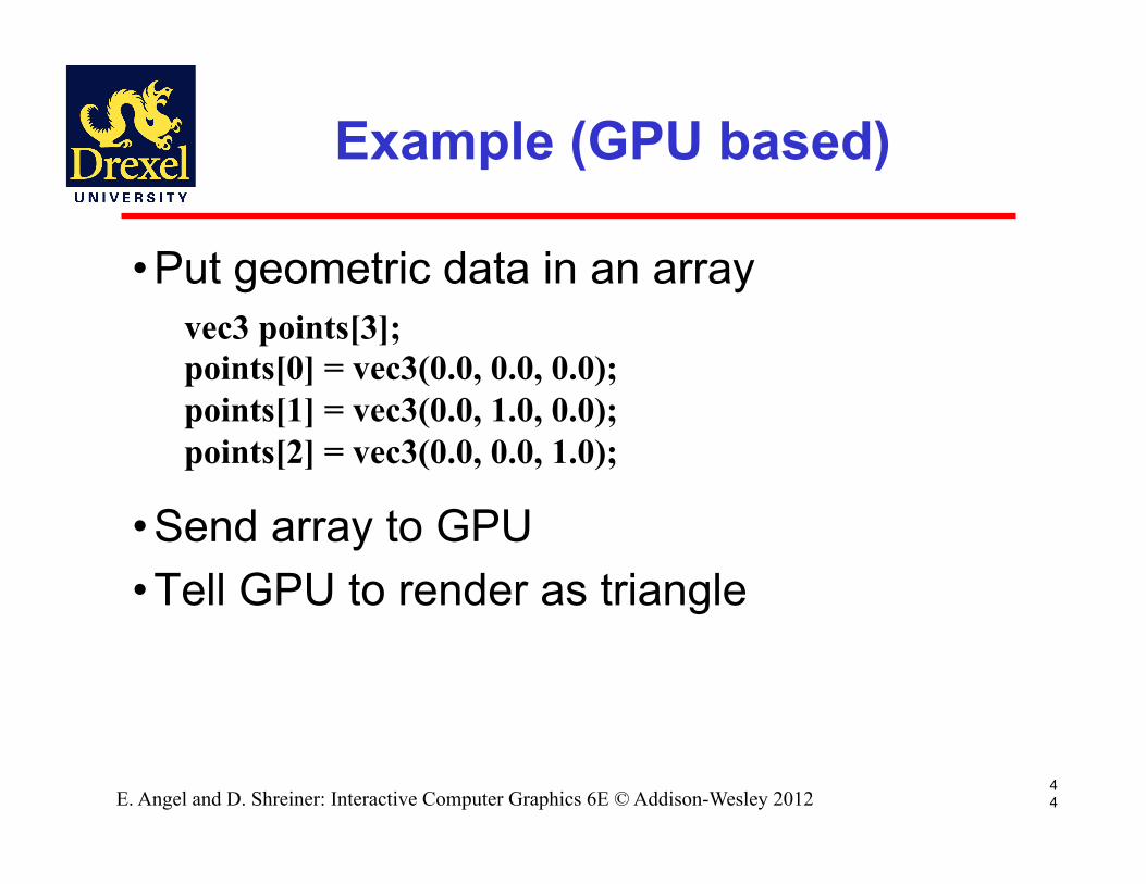
• Put geometric data in an array • Send array to GPU • Tell GPU to render as triangle
Example (GPU based)
44E. Angel and D. Shreiner: Interactive Computer Graphics 6E © Addison-Wesley 2012
vec3 points[3]; points[0] = vec3(0.0, 0.0, 0.0); points[1] = vec3(0.0, 1.0, 0.0); points[2] = vec3(0.0, 0.0, 1.0);

45E. Angel and D. Shreiner: Interactive Computer Graphics 6E © Addison-Wesley 2012
Camera Specification
• Six degrees of freedom - Position of center of lens - Orientation
• Lens • Film size • Orientation of film plane
46E. Angel and D. Shreiner: Interactive Computer Graphics 6E © Addison-Wesley 2012
Lights and Materials
• Types of lights - Point sources vs. distributed sources - Spot lights - Near and far sources - Color properties
• Material properties - Absorption: color properties - Scattering
• Diffuse • Specular