Intensifying screens & films
41
-
Upload
vishwanath-rs -
Category
Health & Medicine
-
view
208 -
download
3
Transcript of Intensifying screens & films


2

3
CASSETTE
Protection:•Exposure to light•Bending and Scratching•Film in close contact with screen.
FRONT: Radiolucent material like aluminum, carbon fiber.
BACK: Lead foil to prevent backscatter

4

5
6
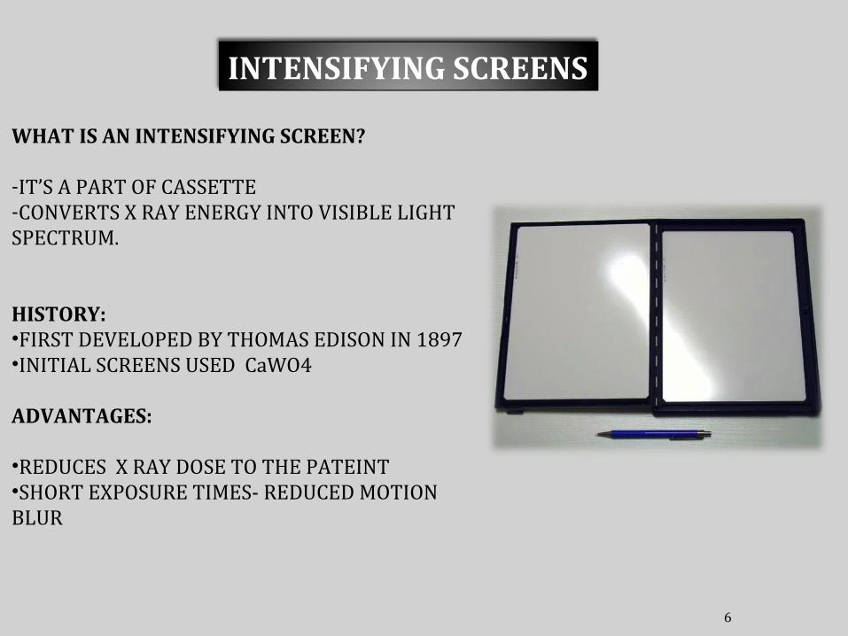
INTENSIFYING SCREENS
WHAT IS AN INTENSIFYING SCREEN?
-IT’S A PART OF CASSETTE-CONVERTS X RAY ENERGY INTO VISIBLE LIGHT SPECTRUM.
HISTORY:•FIRST DEVELOPED BY THOMAS EDISON IN 1897•INITIAL SCREENS USED CaWO4
ADVANTAGES:
•REDUCES X RAY DOSE TO THE PATEINT•SHORT EXPOSURE TIMES- REDUCED MOTION BLUR

7
PRINCIPLE BEHIND INTENSIFYING SCREENS?
LUMINISCENCE : Emission Of Light By A Substance
• Light is emitted instantaneously(<10-8 sec)
• Stops after the stimulus is removed
• Conventional
• Emission of light is delayed beyond 10-8 sec.• Continues to emit light (after glow).
• Digital radiography.


9
BASE
PROTECTIVE COATING
REFLECTING LAYER
PHOSPHOR LAYER
CONSTRUCTION
High grade cardboard or polyester plastic
Titanium dioxide
Cellulose compoundPrevents static electricityPhysical protectionSurface Cleaning

10
PHOSPHOR LAYER : FUNCTION OF THIS LAYER IS TO CONVERT FEW ABSORBED X RAY PHOTONS INTO MANY LIGHT PHOTONS BY PHOTOELECTRIC EFFECT.
PHOSPHOR
X - RAYSLIGHT PHOTONS

11
PHOSPHOR CRYSTALS-SUSPENDED IN PLASTIC
Most frequently used:- Calcium Tungstate(CaWO4)-Superseded by various Rare earths:
Lanthanum oxybromide. Lanthanum oxysulfide. Gadolinium oxysulfide. Yttrium oxysulfide. Barium lead sulfate. Barium fluorochloride.
RARE EARTH PHOSPHORS: - THE TERM IS USED NOT BECOS THEY ARE RARE BUT BECOS THEY ARE DIFFICULT TO SEPARATE FROM THE EARTH. - 97% OF THE RARE EARTHS ARE FROM CHINA.

• High X-Ray absorption efficiency
• High X-Ray to light efficiency
• Emission spectre matched to film sensitivity
• Fast light emission
• Absence of afterglow
• Uniform light output i.e. uniform dispersion in suspension media.
DESIRABLE FEATURES OF PHOSPHORS:

13
DEPEND ON:
1)Thickness of the phosphor layer.
2) Size of the phosphor crystals.
3) Presence or absence of light-absorbing dye in the phosphor layer.
4) Phosphor conversion efficiency.
SPEED OF THE SCREENS

Speed ranges from 100(slow) to 1200(fast)
100-------------Reference screen
200-------------Requires half the exposure of the reference screen to produce the same level of luminescence.
Greater efficiency = less exposure = faster
Speeds for routine work: 200 – 800
Speeds for high detail: 50 – 100
Conversely, any measure taken to increase the intensification factor of the screen increases the unsharpness of the image.

15

16
DECREASE IN CLARITY IS PRIMARILY DUE TO DIFFUSION OF LIGHT LESS SHARP BORDERSINCREASED THICKENSS CAUSES INCREASED DIFFUSIONDECREASED THICKENESS CAUSES DECREASED DIFFUSION

17
SCREEN – FILM CONTACT:
Cassette: light tight containerHolds the film in tight contact with the screens over its entire surface

18
WIRE MESH TEST

19
Standard Film sizes 8” x 10”10” x 12”11” x 14”14” x 17”14” x14”12”x12”
• Film is a media that makes a permanent record of the image
• The energy of the x ray beam is converted into light by intensifying screens, and this is used to expose the film
X RAY FILM

20
Film construction:Film consists of a photographically active or radiation sensitive, emulsion that is usually coated on both sides of a transparent sheet or base.
EMULSION
EMULSION

21
FUNCTION : Support for the emulsion
3 characteristics:
•No visible pattern or should not absorb light•Flexibility, thickness and strength-ease of processing•Dimensional stability-shape and size should not change over time
Originally base was made from CELLULOSE NITRATE – flammable
Now CELLULOSE TRIACETATE BASE and POLYESTER (DMT and Ethylene glycol)
Base is adhered to emulsion using a thin layer of glue.
FILM BASE
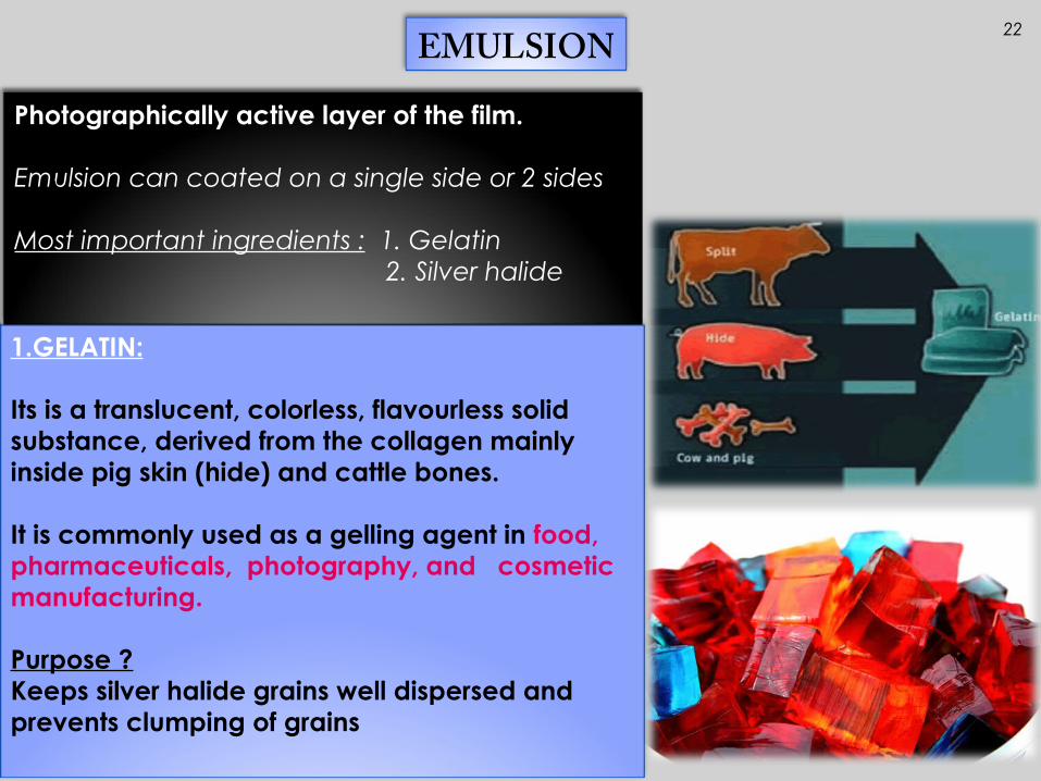
22EMULSION
1.GELATIN:
Its is a translucent, colorless, flavourless solid substance, derived from the collagen mainly inside pig skin (hide) and cattle bones.
It is commonly used as a gelling agent in food, pharmaceuticals, photography, and cosmetic manufacturing.
Purpose ?Keeps silver halide grains well dispersed and prevents clumping of grains
Photographically active layer of the film.
Emulsion can coated on a single side or 2 sides
Most important ingredients : 1. Gelatin 2. Silver halide
23
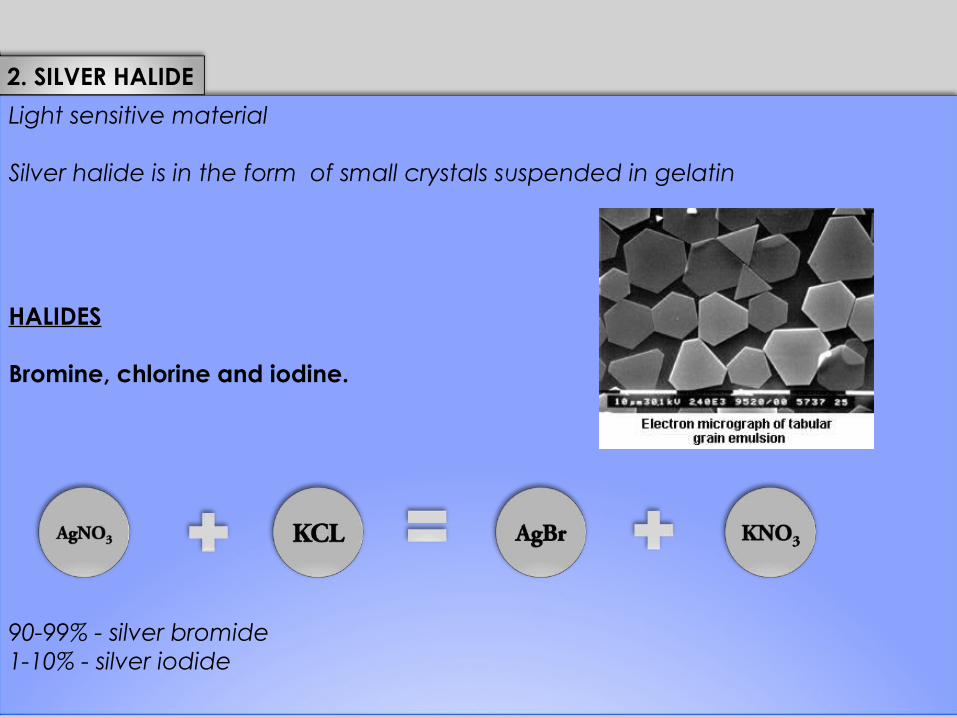
Light sensitive material
Silver halide is in the form of small crystals suspended in gelatin
HALIDES Bromine, chlorine and iodine.
90-99% - silver bromide1-10% - silver iodide
2. SILVER HALIDE

24
Ag Br
Cubic lattice/ crystal size: 1.0-1.5 microns
One cubic cm emulsion: 6.3x10⁹ grains
Each grain: 1,000,000 to 1,000,000 silver ions

25
GUNREY MOTT HYPOTHESIS
Sensitivity speck or defect
X RAY Photon
Silver Atoms Pileup
Latent imagesite
The clumps of silver can be seen with electron microscopy and are termed LATENT IMAGE CENTERS.At these sites developing process will cause visible silver deposit.
26
PHOTOGRAPHIC CHARECTERISTICS OF AN X RAY FILM
What is an exposure?
How the film responds to the exposure ?
Exposure = mA x Secs= mAs
Exposure of the x ray films produces Film blackening or Density.

27
PHOTOGRAPHIC DENSITY
Measurement of film blackness is called PHOTOGRAPHIC DENSITY.
Degree of blackening depends upon :
1.Intensity of radiation2.Silver grains/unit area
Increased intensity = increased blackening
Density = Log Io/ It
Io = Intensity of radiation reaching the filmIt = Intensity of the radiation transmitted.
Density= Log Io/It= Log 10/1 = 1

28
Useful densities in diagnostic radiology range from 0.3 to 2
0.3 ------- 50% of light transmitted’2 ------- 1% of light transmitted
Density increase of 0.3 - The opacity is doubled. - Transmitted light is halved.

29
BASE DENSITY AND FOG
Base density: 0.07
Caused by the plastic material & the blue dye used to make film base.
Fog: 0.05
the density resulting from developed unexposed silver grains.
BASE DENSITY + FOG: 1.12
Why is density expressed as Logarithm?
•Large differences can be expressed on a small scale•Physiologic response of the eye to intensities is logarithmic•Superimposition of densities can be best described as logarithmic.

30
CHARECTERISTIC CURVE(H &D CURVE)
RELATIONSHIP BETWEEN DENSITY AND EXPOSURE
A film is given a series of Exposures.
Developingthe film and plotting the resulting density against known exposure gives the H&D curve.

31
4 properties can be derived:
1.Fog level2.gamma3.Speed4.Latitude
FOG LEVEL:
•DECREASED CONTRAST•INHERENT FOG LEVEL: 0.12•ADDITIONAL FOG LEVEL CAN OCCUR DURING STORAGE.

32
Film Gamma
Defined as maximum slope of charect-eristic curve.
Formula
Gamma : D1 - D2
Log E2 – Log E1
Ranges from 2.0 to 3.5.
In radiology gamma is of little value:
-short slope-slope of the curve over entire range of densities is useful
D1
D2
Log E1
Log E2

33
SPEED
Film B is 0.3 log relative exposure units to the right of the Film A
Both the films show identical contrast
Film B requires twice the exposure as film A

34
LATITUDE
Range of log relative exposure(mAs) that will produce the density within the acceptable range for diagnostic radiology
Film B is having a greater lattitude than Film A
The greater the lattitude the less the contrast.

35
Radiographic Contrast
Contrast is the difference in luminance and/or color that makes an objectdistinguishable.

36

37
Radiographic contrast depends on
1.Subject contrast2.Film contrast
Subject contrast is affected by:
1. Thickness of the subject.2. Density and atomic differences of the subject.3. Radiation energy (kVp).4. Contrast material.5. Scatter radiation
Film contrast is affected by:
1.Film gamma2.Screen or Direct exposure3.Film density4.Film processing
38
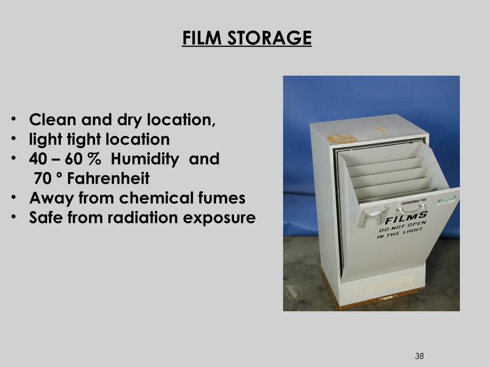
FILM STORAGE
• Clean and dry location, • light tight location• 40 – 60 % Humidity and 70 º Fahrenheit• Away from chemical fumes• Safe from radiation exposure

39
Why x ray image is viewed as a transparency?
Why can’t it be printed on a paper and viewed ?

40
References:
Christensen’s Physics of Diagnostic Radiology

41