Intensified Liquid-Liquid Extraction Technologies in Small ...
12
www.technology.matthey.com https://doi.org/10.1595/205651319X15669171624235 Johnson Matthey Technol. Rev., 2019, 63, (4), 299–310 299 © 2019 Johnson Matthey Panagiota Angeli*, Eduardo Garciadiego Ortega, Dimitrios Tsaoulidis ThAMeS Multiphase, Department of Chemical Engineering, University College London, Torrington Place, London, WC1E 7JE, UK Martyn Earle The QUILL Research Centre, School of Chemistry and Chemical Engineering, The Queen’s University of Belfast, University Road, Belfast, BT9 5AG, UK *Email: [email protected] Solvent extraction is a key separation process in several industries. Mixer-settlers and agitated or pulsed columns are mainly used as liquid- liquid contactors. However, these units require large solvent inventories and long residence times, while flow fields are often not uniform and mixing is poor. These drawbacks can be overcome with process intensification approaches where small channel extractors are used instead. The reduced volumes of small units in association with the increased efficiencies facilitate the use of novel, often expensive, but more efficient and environmentally friendly solvents, such as ionic liquids. The small throughputs of intensified contactors, however, can limit their full usage in industrial applications, thus robust scale- up strategies need to be developed. This paper reviews promising intensified technologies for liquid-liquid extractions based on small channels. In particular, extractions in single channels and in confined impinging jets are considered. The increase in throughput via scale- out approaches with appropriate manifolds is discussed, based on the use of many channels in parallel. The combination of small channels and centrifugal forces is exploited in counter-current chromatography (CCC) systems where many mixing and settling steps are combined within the contactors. Scale up is possible via centrifugal partition chromatography (CPC) configurations. 1. Process Intensification Process intensification (PI) is a design framework which aims to create smaller, safer and more efficient processes. There have been many reviews on process intensification and attempts to define it since its inception over 20 years ago. Process intensification approaches often involve the reduction in the size of the process units to increase heat and mass transfer rates and, in multiphase processes, to manipulate and control the flow patterns and increase the interfacial areas. The benefits of operating in small scale units stem from the thin fluidic films and the decreased diffusion distances, which increase the heat and mass transfer rates resulting in homogeneous concentration and temperature fields. Residence times can be shortened, thus avoiding side reactions, increasing selectivity and reducing waste. The decrease in length scales also increases the importance of surface or interfacial forces over inertial, viscous and gravitational ones; as a result, flow patterns in two-phase systems tend to be regular. Channel walls with different wettabilities can be fabricated to separate two-phase mixtures or impose certain patterns in the channels. The large interfacial area-to-volume ratios benefit mass transfer, while the large channel surface-to-volume ratios improve heat transfer. Flows are laminar in Intensified Liquid-Liquid Extraction Technologies in Small Channels: A Review
Transcript of Intensified Liquid-Liquid Extraction Technologies in Small ...
www.technology.matthey.com
https://doi.org/10.1595/205651319X15669171624235 Johnson Matthey Technol. Rev., 2019, 63, (4), 299–310
299 © 2019 Johnson Matthey
Panagiota Angeli*, Eduardo Garciadiego Ortega, Dimitrios TsaoulidisThAMeS Multiphase, Department of Chemical Engineering, University College London, Torrington Place, London, WC1E 7JE, UK
Martyn EarleThe QUILL Research Centre, School of Chemistry and Chemical Engineering, The Queen’s University of Belfast, University Road, Belfast, BT9 5AG, UK
*Email: [email protected]
Solvent extraction is a key separation process in several industries. Mixer-settlers and agitated or pulsed columns are mainly used as liquid-liquid contactors. However, these units require large solvent inventories and long residence times, while flow fields are often not uniform and mixing is poor. These drawbacks can be overcome with process intensification approaches where small channel extractors are used instead. The reduced volumes of small units in association with the increased efficiencies facilitate the use of novel, often expensive, but more efficient and environmentally friendly solvents, such as ionic liquids. The small throughputs of intensified contactors, however, can limit their full usage in industrial applications, thus robust scale-up strategies need to be developed. This paper reviews promising intensified technologies for liquid-liquid extractions based on small channels. In particular, extractions in single channels and in confined impinging jets are considered. The increase in throughput via scale-
out approaches with appropriate manifolds is discussed, based on the use of many channels in parallel. The combination of small channels and centrifugal forces is exploited in counter-current chromatography (CCC) systems where many mixing and settling steps are combined within the contactors. Scale up is possible via centrifugal partition chromatography (CPC) configurations.
1. Process Intensification
Process intensification (PI) is a design framework which aims to create smaller, safer and more efficient processes. There have been many reviews on process intensification and attempts to define it since its inception over 20 years ago. Process intensification approaches often involve the reduction in the size of the process units to increase heat and mass transfer rates and, in multiphase processes, to manipulate and control the flow patterns and increase the interfacial areas. The benefits of operating in small scale units
stem from the thin fluidic films and the decreased diffusion distances, which increase the heat and mass transfer rates resulting in homogeneous concentration and temperature fields. Residence times can be shortened, thus avoiding side reactions, increasing selectivity and reducing waste. The decrease in length scales also increases the importance of surface or interfacial forces over inertial, viscous and gravitational ones; as a result, flow patterns in two-phase systems tend to be regular. Channel walls with different wettabilities can be fabricated to separate two-phase mixtures or impose certain patterns in the channels. The large interfacial area-to-volume ratios benefit mass transfer, while the large channel surface-to-volume ratios improve heat transfer. Flows are laminar in
Intensified Liquid-Liquid Extraction Technologies in Small Channels: A Review

300 © 2019 Johnson Matthey
https://doi.org/10.1595/205651319X15669171624235 Johnson Matthey Technol. Rev., 2019, 63, (4)
many cases and, combined with the regular flow patterns, can be modelled more easily. The small volumes reduce the risks of handling hazardous materials, while accidents are better contained. Intensification is often linked to continuous flow processing. The homogeneous conditions in channels facilitate monitoring and allow modularity where the process steps are separated by controlling, for example, the temperature or the addition of reactants along the channel.Processes involving two immiscible liquids are
widespread industrially and intensification has already been shown to benefit emulsifications (1–3) and reactions including hydrogen peroxide oxidations and (trans-)esterifications (4, 5). Among two-phase liquid processes, extractions are commonly used for the separation of materials in, among others, the pharmaceutical (proteins, antibiotics in aqueous two-phase systems), energy (uranium in nuclear spent fuel reprocessing; carbon dioxide or hydrogen sulfide removal) and mining (copper and precious metals) sectors (6, 7). Industrially, extractions are carried out in mixer settler units or pulsed columns which suffer from inhomogeneous and not well-characterised flow fields and large inventories. Intensified approaches have already been applied in the extraction of bio-based chemical precursors (8, 9), transition metals (10) including platinum group metals (11), lanthanides (12, 13) and actinides (14, 15), acetone in toluene-water systems (16–18). Because of the improved efficiency and reduced volumes of the small units, the amount of solvent required is reduced; this paves the way for the use of novel, efficient but sometimes expensive solvents (such as ionic liquids). In addition, external fields such as centrifugal, magnetic and ultrasonic can easily be applied to improve mixing, separation or reaction rates. The majority of the intensified demonstrations are in single channels. For industrial applications it is necessary to increase throughput by increasing the number of channels, which is presently a major challenge.In what follows, liquid-liquid extractions in
intensified small-scale contactors are reviewed. These include extractions in single channels and in confined impinging jets cells as well as approaches to increase throughput via scale out, where many parallel channels are combined with appropriate manifolds. Developments on the use of centrifugal forces to enhance separations in small channels in CCC systems are discussed. The combination of intensified technologies with novel ionic liquid solvents is also considered.
2. Extractions in Small Channels
When two immiscible liquids flow together in small channels, many flow patterns can form, ranging from segmented to annular and dispersed flows, as can be seen in the example in Figure 1. Parallel flows, where the two liquids flow in continuous layers next to each other, can also occur, usually by modifying either the wetting properties or the geometry of the channel walls. The segmented, plug or slug flow pattern has
been extensively studied because it appears for a wide range of phase flow rates and has been linked to high mass transfer rates. In this pattern, the dispersed phase moves as drops with size larger than the channel diameter (plugs) separated by slugs of the continuous phase (see Figure 1). Usually, there is a thin film of the continuous phase between the plugs and the channel wall. As the film is usually very thin, axial dispersion is limited. In addition, within each phase, circulation patterns are established which improve radial mixing (see Figure 2). As a result, a plug-flow reactor configuration establishes with improved radial and decreased axial mixing that ensures uniform residence times for the reactants. In the small channel contactors, the flow
characteristics and the mass transfer performance are closely related. The plug and slug lengths
Fig. 1. Diagram of a typical flow pattern map in 2 mm channels using water (dispersed phase) and kerosene (continuous phase). The x-axis shows the volumetric flow rate of the dispersed (non-wetting) phase (Qd) and the y-axis shows the volumetric flow rate of the continuous (wetting) phase (Qc). The segmented flow pattern is surrounded by transitional flow regimes, where more than one flow patterns are found in the channel
Transitional flow regimes100
100
10
10Qd, ml min–1
Qc,
ml m
in–1
1
1
0.1
0.1
Drop/dispersed flow
Annular flow
Segmented/plug flow

301 © 2019 Johnson Matthey
https://doi.org/10.1595/205651319X15669171624235 Johnson Matthey Technol. Rev., 2019, 63, (4)
determine not only the interfacial area but also the mixing characteristics within the two phases. Apart from the flow rate ratio and the properties of the two phases, the plug and slug lengths depend significantly on the geometry of the inlet. Plug lengths have been reported by many investigators (19, 20) but there is no single model to predict them a priori.Interfacial areas can be calculated from the
measured plug and slug lengths and shapes of the front and back ends of the plugs. It has been found that the specific interfacial area (interfacial area per unit volume of the contactor) depends on the channel diameter, the flow rate ratio, the total velocity and the inlet geometry. Interfacial areas ranging from 2760 m2 m–3 to 4800 m2 m–3 in 0.5 mm, 0.75 mm and 1 mm internal diameter (ID) channels have been reported by Kashid et al. (21), whilst Li and Angeli (13) measured specific interfacial areas up to 8500 m2 m–3 for smaller channels of 0.2 mm ID, using high-speed imaging. In larger channels, with a diameter of 4 mm, the specific interfacial area decreased to values up to 880 m2 m–3. The circulation times within the plugs or slugs can be calculated when the velocity fields in the phases are known. Velocity field measurements have been carried out with particle image velocimetry (PIV) (22) or predicted from computational fluid dynamics (CFD) simulations (23). The results have shown that mixing is improved as the velocity increases and the plug and slug lengths decrease. Segmented flow contactors have been used for
many liquid-liquid mass transfer and reaction operations. In the case of fast reactions, the overall rate of the process is primarily controlled by the rate of mass transfer and microreactors have been shown to intensify processes. A typical example is the transesterification reaction of vegetable oils to produce biodiesel, where yields over 90% can be achieved under 30 s residence time in 240 µm hydraulic diameter channels (24). Regarding liquid-liquid metal extractions, combined with ionic liquids as the solvent phase, microchannels have been applied to the separation of uranium (25) and
europium (13) for spent nuclear fuel reprocessing and for analysis in nuclear waste management. Channel sizes between 0.2 mm and 2 mm were used and extraction efficiencies >80% were achieved in <30 s. Pedersen et al. (26) achieved separation >90% of titanium-45 for use in positron imaging in less than 15 s in 0.75 mm perfluoroalkoxy (PFA) tubing. The overall volumetric mass transfer coefficient
for a solute being transferred from the aqueous to the organic phase is given by Equation (i) (15):
k lnC CC C
iL aqaq eq aq init
aq eq aq fin
α ετ τ
=−
−
−
1
2 1
, ,
, ,
( )
where εaq is the volume fraction of the aqueous phase, Caq,eq is the concentration of the solute in the aqueous phase at equilibrium, Caq,init is the concentration of the solute in the aqueous phase at residence time τ1 and Caq,fin is the concentration of the solute in the aqueous phase at residence time τ2. High-value precious metals such as platinum
and palladium have also been extracted using intensified contactors. Yin et al. (11) and Kriel et al. (27, 28) extracted high-value metals (Pt, Pd) using parallel flow contactors. These metals are often found in mixtures at low concentrations (for example, from spent automotive catalysts) and their extraction may not be economic using conventional devices. In particular, Kriel et al. (27) demonstrated the extraction, scrub and stripping processes in flow channels with overall recovery rates over 95%. By modelling the flowsheet of spent nuclear fuel reprocessing using intensified extractors for the first time, Bascone et al. (29) showed important reductions in solvent use and in radiolytic degradation.To increase throughput, large channel sizes should
be considered that still preserve the benefits of small-scale operations, such as thin fluid films and enhanced heat and mass transfer rates. The extraction efficiencies and the volumetric mass transfer coefficients for channels between 0.5 mm and 4 mm ID were measured by Tsaoulidis and Angeli (25) and kLα as high as 0.06 s–1 were found, even at the largest channels. The kLα increased as the channel diameter decreased. In smaller channels, however, the pressure drop increased and the throughput decreased. There is, therefore, a trade-off between mass transfer performance, throughput and energy requirements which needs to be carefully considered when designing plug flow separators.
Fig. 2. Schematic of the circulation patterns found in segmented (plug) liquid-liquid flows in small channels
Slug Plug PlugSlug Slug

302 © 2019 Johnson Matthey
https://doi.org/10.1595/205651319X15669171624235 Johnson Matthey Technol. Rev., 2019, 63, (4)
To integrate the small channel extractors with the rest of the process, the separation of the two phases at the end of the channel should be considered. In small channels, wettability and interfacial effects are important and have been successfully implemented for the separation of the organic and aqueous phases. Separators with side channels or membranes that are preferentially wetted by the organic or aqueous phases have been tested. Currently, however, there are few commercially available options (for example, Zaiput Flow Technologies, USA); for parallel processing with many channels (see Section 4 below) the separator capital costs would scale linearly with the number of channels. Alternatively, gravity separators can still be used for systems with high throughput and sufficient density difference (>0.1 g cm–3, (30)). In gravity settlers, however, the mass transfer between the phases can continue and diminishes the benefits of well-controlled conditions of the small channel.
3. Intensified Impinging Jets Cells
An alternative option for increasing throughput in small channels is to increase the velocities of the two fluidic streams in an impinging jets inlet configuration. In recent years, there has been
a renewed interest in using confined impinging jets reactors (CIJR) for many applications, such as crystallisation (31), nanoparticle synthesis using liquid precipitation (32), micromixing (33), extraction (15) and bioreactions (34). The high energy dissipation rates due to collision and redirection of the fluidic jets in the impingement zone make the contactor particularly suited for applications where rapid mixing of the fluids is necessary. When the two jets are immiscible liquids, then the large energy dissipation rates result in the formation of dispersions. A typical configuration of a cylindrical CIJR at 180° nozzle angle is shown in Figure 3(a). The mixing and dispersed phase size are affected
by a number of geometric characteristics, such as main channel (D) and nozzle (dj) size, main channel to nozzle size ratio, inter-nozzle distance (Id), nozzle height and impingement angle. The main challenge in developing confined impinging jets contactors for a particular application is the quantification of the effects of the parameters on the resulting drop sizes. There are many studies on impinging jets with miscible liquids, which demonstrate that for improved mixing the two opposing jets should have similar momentum so that they collide in the middle plane (35). Studies of impinging jets in confined spaces with immiscible liquids are very limited. The
Fig. 3. (a) Typical configuration of confined impinging jets contactor; (b) photograph of dispersion in the impingement zone; (c) drop size distribution in the main channel (Photograph from (35) Creative Commons Attribution (CC BY))
(a) (b)
(c)
Nozzle height
Liquid 1 Liquid 2
Stainless steel nozzle(dj)
Impingementzone
Mainchannel(D)
Stainless steelnozzle
Acrylic block
Dispersion in the impingement zone
Drop size distribution with impinging jets cell
Drop size, mm
%
40
30
20
10
00.0 0.1 0.2 0.3 0.4
in

303 © 2019 Johnson Matthey
https://doi.org/10.1595/205651319X15669171624235 Johnson Matthey Technol. Rev., 2019, 63, (4)
drop size has been related to the energy dissipation rate, while the uniformity of the dispersions depends on the geometric design of the contactor, the phase ratio and the intensity of mixing in the impingement zone (36). The energy dissipation rate (ε) can be described as the ratio of the power available due to kinetic energy change (K) at collision over the mixing volume of the impingement zone (Viz), according to Equation (ii):
ερ
=KV
iiiz
( )
where
K m u m u iii∝ +
1 12
2 22
2 2( )
and m1 and m2 are the mass flow rates (kg s–1) of Phase 1 and Phase 2 respectively, u1 and u2 are the average velocities of Phase 1 and Phase 2, respectively, and ρ is the density of the mixture.The Sauter mean diameter, given by Equation
(iv):
D dd
ivin
i
in
i
[ , ] ( )3 23
2=ΣΣ
(where n is the number of drops and di is the diameter of the drop i in the distribution) has been related to the specific energy dissipation rate as follows (37), Equation (v):
D k va[ , ] ( )3 2 = −ε
The dependence of the average drop size on the energy dissipation in the impingement zone is presented in Figure 4 for two different aqueous/organic phase systems (15). As can be seen, at low energy dissipation values, the drop size depends on the geometry of the system and the fluid
properties, while at larger ε, above 600 W kg–1, the drop sizes converge. Similar results were also found by Siddiqui (2) for aqueous/organic systems in impinging jets contactors with the addition of emulsifiers, while in less viscous systems a stronger dependence of drop size on energy dissipation rate was observed.It has been found that the dispersions formed in
impinging jets have low polydispersity. Tsaoulidis and Angeli (36) reported polydispersity indices (PdI) as low as 0.05, for an oil/water system, for a wide range of jet velocities from 0.17 m s–1 to 6.2 m s–1. Interfacial area-to-volume ratios were significantly affected by the velocities of the jets and the values varied between 2000 m2 m–3 and 12,000 m2 m–3. Siddiqui (2, 3) also reported very narrow drop size distributions in a sunflower oil/water emulsification process with surfactants, for dispersed phase fractions up to 10% and drop sizes less than 10 μm. The few mass transfer studies available have also
revealed high mass transfer coefficients compared to other contactors as can be seen in Table I. kLα can be one to two orders of magnitude higher than in conventional contactors and two to three times higher than in microchannels. Values are similar to those of centrifugal contactors, however, the specific power input for centrifugal contactors can be two to three orders of magnitude higher when compared to a confined impinging jets cell (16). The studies revealed that high mass transfer
coefficients were obtained at short residence times (<4 s), with values up to 1 s–1. Several parameters were found to affect mass transfer, including geometric characteristics and flow rate ratio. In Figure 5(a), mass transfer rates were calculated for two different main channel sizes i.e. 2 mm and 3.2 mm. It is shown that kLα depend on channel size at short residence times but are independent of the channel sizes at long times. The 3.2 mm channel should then be preferred because it has higher throughput and reduced pressure drop compared to the 2 mm channel. The mass transfer coefficient also increases with increasing collision velocities of the two jets (shown as the sum of the two velocities, utot in Figure 5(b)). The velocity of the liquid jets will define the position of the point of impingement (Figure 6) and will affect the uniformity of the flow pattern in the main channel as well as the drop size distribution.Impinging jets systems have been used for more
than four decades now but it is still not possible to determine accurately the effects of the dominant variables including aspect ratio of jet inlets, dead
Fig. 4. Effect of specific energy dissipation rate (ε) on Sauter mean drop diameter D[3,2] in confined impinging jets cells (data adapted from Tsaoulidis et al. (15))
0.500.450.400.350.300.250.200.150.100.05
00 500 1000 20001500
ε, W kg–1
D[3
,2],
mm
Aqueous-organic systemγ = 32 mN m–1
Aqueous-organic systemγ = 11 mN m–1
D = 3 mm; dj = 0.5 mmD = 3 mm; dj = 0.25 mmD = 2 mm; dj = 0.25 mmD = 3.2 mm; dj = 0.5 mmD = 3.2 mm; dj = 0.25 mmD = 2 mm; dj = 0.25 mm

304 © 2019 Johnson Matthey
https://doi.org/10.1595/205651319X15669171624235 Johnson Matthey Technol. Rev., 2019, 63, (4)
volume at the mixing section, fluid properties on the drop size and the mass transfer performance of the contactors.
4. Scale Out of Single Channel ContactorsHarmsen (41) identified four hurdles that any PI innovation must address before it can be
implemented industrially. These are: (a) risk of failure by combining novel aspects; (b) scale-up knowledge uncertainty; (c) equipment unreliability; and (d) improved safety, health and environmental risks. The main hurdle faced by single-channel contactors is the scale-up uncertainty. Currently, there are no applications of small-channel extractors at large commercial or pre-commercial scales reported in the literature.
Fig. 5. Overall volumetric mass transfer coefficient, kLα, as a function of residence time: (a) for two different main channel sizes (D = 3.2 mm, dj = 0.25 mm, Id = 3.2 mm; D = 2 mm, dj = 0.25 mm, Id = 2 mm); (b) for different total jet velocities utot (D = 3.2 mm, dj = 0.5 mm, Id = 3.2 mm) (data adapted from Tsaoulidis et al. (15))
1.2(a) (b)
1.00.80.60.40.2
00 2 4 6 8
Residence time, s0 2 4 6 8
Residence time, s
k Lα,
s–1
k Lα,
s–1
D = 3.2 mmD = 2 mm
00.10.20.30.40.50.60.7 utot
5.1 m s–1
3.4 m s–1
Table I Overall Mass Transfer Coefficients (kLα) in Intensified and Conventional ContactorsEquipment System kLα, s–1 ReferenceIntensified impinging jetsConfined impinging jets cell TBP/kerosene-U-HNO3 0.15–1.05 (15)
Two impinging jets device H2O-acetone-toluene 0.001–0.19 (18)
Impinging jets extractor Butanol–succinic acid–H2O 0.015–0.2 (16)
Intensified small channelsMicrochannels (D = 0.5–4 mm) TBP/ionic liquid-U-HNO3 0.05–0.3 (25)
Centrifugal extractor Aqueous NaOH-(butyl acetate, iso-amyl acetate, hexyl acetate) 0.2–2 (38)
Conventional contactorsMixer-settler NPH-TBP-HNO3 0.5–13.3 (x 10–5) (39)
Rotating disc contactor Toluene-H2O-acetone 4–9.5 (x 10–3) (40)
Fig. 6. Effect of kinetic energy (K) ratio of the two jets on the flow pattern in the impingement zone
K1=K2
K1=K2
K1≠K2
K1≠K2Fluid 1
K1
Fluid 1
K1
Fluid 2
K2
Fluid 2
K2

305 © 2019 Johnson Matthey
https://doi.org/10.1595/205651319X15669171624235 Johnson Matthey Technol. Rev., 2019, 63, (4)
While single small channel flow contactors and reactors are highly efficient, the scale-up of the throughput without losing the small-scale advantages remains a main challenge. Scale-up can be achieved by increasing the number of channels operating in parallel (‘scale out’ or ‘number-up’). It is not trivial, however, to reproduce accurately the flow conditions of a single channel in many parallel ones. The challenge is to design a flow distributor within the process-specific maldistribution tolerance of the total flow rate and of the flow rate ratio of the two phases for each channel. Scale out for single-phase processes requires a
flow distributor that can achieve almost the same flow rate and thus residence time, in all channels. Single-phase flow distributors are commonly encountered in multi-tubular reactors, catalytic converters and other honeycomb catalysts. The distributors usually take one of two forms, bifurcation or consecutive manifolds, as shown in Figure 7. The consecutive manifold has a small footprint compared to the bifurcation one. Approaches based on resistance networks have been used to design manifolds that reduce flow non-uniformities among the channels (42).In the case of multiphase systems, both the
residence time and the flow rate ratio of the two phases are critical for the performance of the process and should be constant among the many channels of the manifold. There are two types of two-phase flow distributors: split-combine and combine-split
(Figure 8). Combine-split designs first bring the two fluids in contact and then distribute the two-phase mixture into as many channels as necessary. Combine-split distributors do not have dead volumes and have been successfully designed by Hoang et al. (43) at a chip-scale; the design has been tested for up to eight channels but it may be unfeasible to increase further the number of channels. Split-combine distributors (or double manifolds)
distribute each of the single-phase fluids independently into as many channels as necessary and then bring them in contact. This type of distributor can, in turn, be either a bifurcation or a consecutive manifold. Maldistribution of gas-liquid flows in double
manifolds and the effects of manufacturing tolerances were studied experimentally by Al-Rawashdeh et al. (44) for square main channels with 1 mm side. The authors achieved deviations in the residence time below 20% by controlling the pressure drop in the distribution sections. Garciadiego Ortega et al. (45) developed a method to analyse the two-phase flow maldistribution and used a resistance network model to simulate the double manifolds. The effect of the number of channels on the maldistribution was also studied and scaling-laws for the design of these distributors were proposed as well as a procedure for an effective and economic double manifold design. The first step is to define the single-channel size and flow rates for a particular process and define the sensitivity of its performance to flow maldistribution. This defines the maldistribution tolerances, which determine the dimensions of the flow distributor. Finally, the pumping requirements are calculated. There is a trade-off between pumping requirements and maldistribution, with low maldistribution tolerances resulting in high pumping costs.
Fig. 7. Schematics of: (a) a consecutive manifold; (b) a bifurcation manifold
(a)Distribution section
Distribution section
Main section
Main section
Collection section
Collection section(b)
Fig. 8. Multiphase flow distribution strategies: (a) split-combine, where both phases are distributed separately and then brought into contact; (b) combine-split, where the phases are brought together first and then the two-phase flow is split into several channels
Split-combine
W in
O in
W in
O in
MixoutMixout
Mixout
Mixout
Combine-split(a) (b)
306 © 2019 Johnson Matthey
https://doi.org/10.1595/205651319X15669171624235 Johnson Matthey Technol. Rev., 2019, 63, (4)
5. Counter-Current Chromatography using Ionic Liquid Solvent Systems
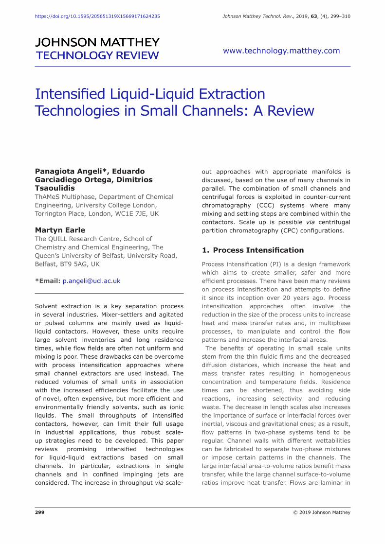
A promising intensified separation technology is high-performance CCC. It is a form of liquid-liquid extraction that achieves separation by repeated partitioning of solutes between two immiscible liquid phases, as they interact in a continuous length of coiled tubing under centrifugal and Archimedean forces. The tubing is wrapped around a cylindrical drum (called a bobbin) to form typically a three-dimensional (3D) helical configuration with one or several layers. Within the CCC column, one of the liquid phases is held stationary by a combination of hydrodynamic and hydrostatic forces generated as a result of rotating the column in planetary motion, while the other mobile phase is continuously pumped through the coil and serves to transport the solutes through the system. The J-type CCC is the most commonly used, where the bobbin is mounted on a planetary axis, driven by a central axis so that the column rotates about its own axis while it revolves around the central axis at the same velocity in the same direction (Figure 9(a)). The double rotation of the column during its planetary motion produces a variable centrifugal force field. This force field creates a unique mixing pattern in which a series of sequential mixing and settling zones are generated simultaneously along the length of the column. These alternating mixing and settling steps are essential to the chromatographic process as they
promote solute transfer between the phases and therefore, separation of species with different partition coefficients.In the last decade, the use of ionic liquids either
as solvents or additives in liquid-liquid extractions has expanded considerably because of their unique properties. Ionic liquids are organic salts that are liquid at room temperature. The stability, phase behaviour and greater solvating power of ionic liquids, together with the ability to design their structure, can increase both the flexibility and performance of separations and allow separations that were not previously considered possible. The combination of the two technologies, ionic liquids and CCC, therefore represents an exciting approach to intensified liquid-liquid separations. However, the use of ionic liquids in CCC is not a trivial task due to their relatively high viscosities, which can introduce significant problems for the majority of traditional CCC machines that are mostly low pressure. To overcome the pressure limitations previously encountered using the CCC technique, AECS-QuikPrepTM Ltd, UK in collaboration with the QUILL Research Centre have reported on the design and construction of a modified high backpressure CCC instrument (Figure 9(b)). The high solvating power of ionic liquids allows separations to be run at very high sample loadings which gives rise to high space-time yields for ionic liquid and CCC separations. The ability to custom design ionic liquids allows a greater range of mobile phases to be employed and enables separations
Fig. 9. (a) Schematics of the operation of a J-type countercurrent chromatographic column showing the coil layout and motion from as viewed from the front (left) and from the side (right); (b) The inside view of the chromatographic coil in the AECS IL-Prep instrument
Flying lead pipe to head and tail of the coil
Stationary sun gear
Sun axis of
rotation
Multilayer coilPlanetary
gearPlanetary axis
of rotation
Axis of rotation
Mixing zone on inner part of
the coil
Settling zone on outer part of
the coil
(a) (b)

307 © 2019 Johnson Matthey
https://doi.org/10.1595/205651319X15669171624235 Johnson Matthey Technol. Rev., 2019, 63, (4)
with pH neutral water as the mobile phase, where previously toxic organic solvents (such as acetonitrile), concentrated salt solutions (such as aqueous dipotassium phosphate), polymers (such as polyethylene glycol) or acids (such as nitric acid) were used. Scale up can be achieved with the increased capacity CPC instrument (46). Ionic liquids have been applied successfully as a major solvent system component for a wide range of separations (47–49) including:(a) Inorganic metal salt separations (cobalt chloride
from nickel chloride from copper chloride) and more recently praseodymium(III) nitrate from erbium(III) nitrate both with water as the mobile phase
(b) Separation of saccharides such as glucose from sucrose and fructose from sucrose
(c) The extraction of aromatic compounds from alkanes (such as cumene from hexane)
(d) The separation of fatty acid derivatives. The combination of ionic liquids with CCC has
been successfully used in the separation of the anticancer drug lentinan at a scale 10–100 times the scales of earlier separations (50). Lentinan is found in shiitake mushrooms (Lentinus edodes) and is used as an adjunct to therapy in combination with chemotherapeutic drugs such as fluorouracil to modulate the body’s immune system activity. Lentinan naturally exists in water and salt solutions but is easily denatured by solvents. This means that for the isolation and purification process of lentinan, water based solvent systems are required. The conventional purification of lentinan normally involves up to 10 steps. An ionic liquid-based aqueous biphasic solvent system (ABSS) was developed using 1-n-butyl-3-methylimidazolium salts [C4mim]Cl / 2.5 M K2[HPO4](aq) (1:1) mixture (51), which allowed lentinan separations on the 1–3 g scale, without denaturing the lentinan. This CCC process used aqueous [C4mim]Cl as the mobile phase and the lentinan was separated from the [C4mim]Cl solution by the addition of ethanol to the [C4mim]Cl phase. The [C4mim]Cl can be recovered and reused after the lentinan has been precipitated. The ethanol can also be recovered by evaporation allowing it to be reused. This leads to a separation process that does not consume solvents or reagents.An improved lentinan process has also
been developed with a novel ABSS based on microemulsions. Surface active ionic liquids such as 1-dodecyl-3-methylimidazolium di(iso-octyl)phosphinate ([C12mim][DiIOP]), when mixed with water and hexane produce a water
immiscible microemulsion phase, which contains 75 mol% water (Figure 10). The aqueous phase is composed of >99% water, which allows water to be used as the mobile phase in CCC separations, with the microemulsion as the stationary phase. This greatly simplifies product isolation since the product does not end up mixed with large quantities of involatile chromatography solvent constituents. Also, this approach does not produce any solvent waste (other than water) making this a very green and inexpensive separation to run. The full lentinan process takes the freeze dried hot water extract of shiitake mushrooms (Figure 11(a)) and precipitates lentinan from this crude extract dissolved in [C4mim]Cl, using ethanol. The precipitated 80% lentinan (Figure 11(b)) is then purified with the water-microemulsion solvent system shown in Figure 10 to give the off-white 95% lentinan shown in Figure 11(c) on the 25 g per run scale. Recent industrial uses of CCC and CPC instruments are in the refining of galantamine from daffodils (for example, BioExtractions (Wales) Ltd, UK) or the red spider lily (52), the purification of cannabinoids and metal ion separations associated with the nuclear industry.
6. Conclusions
Liquid-liquid extractions are widely used for the separation and purification of many compounds. Small channels (up to 4 mm in diameter) and a combination with external fields, such as
Hexane
Microemulsion
Water
Fig. 10. The water-[C12mim][DiIOP]-hexane triphasic solvent system with water as the bottom phase and hexane as the top phase. The middle microemulsion phase is composed of 75 mol% water, 23.5 mol% hexane and 1.5 mol% [C12mim][DiIOP]

308 © 2019 Johnson Matthey
https://doi.org/10.1595/205651319X15669171624235 Johnson Matthey Technol. Rev., 2019, 63, (4)
centrifugal forces, can significantly intensify the process by reducing residence times, improving extraction and extraction efficiencies and reducing the amount of solvent required. Mass transfer coefficients up to 1 s–1 have been measured in the impinging jet contactors. These characteristics have made possible the implementation of novel and often expensive solvents such as ionic liquids with significant improvements to the separation. Droplet-based flows (dispersed or plug flow patterns) in particular have been shown to enhance mass transfer and increase interfacial areas. However, the throughputs are small and scale out would be required before they can be applied to industry. On the other hand, the fast mass transfer rates and well-characterised flow patterns render small channels suitable for analysis and for research on new extractants. Impinging jets have increased throughputs and can produce dispersions with narrow size distribution and large interfacial areas. CCC devices with alternating mixing and settling steps allow separation of species with different partition coefficients and have been used to optimise solvent systems and conditions for separations. High throughputs can be achieved with the increased capacity CPC which has simpler rotor design and fewer moving parts compared to CCC (46, 53). At small scales, the contactor geometry
significantly affects the flow and mass transfer characteristics. Possibilities are open for novel contactor designs that exploit interfacial and wettability effects to establish desirable flow patterns and enhance mass transfer. For the commercial application of the technology in production, robust scale-out designs for two-phase systems need to be further developed and the sensitivity of their performance against flow maldistribution needs to be tested.
Acknowledgements
The research work has been supported by Engineering and Physical Sciences Research Council (EPSRC) grants (EP/P034101/1, EP/R019223, EP/M02699X/1, EP/L018616/1). Eduardo Garciadiego Ortega also acknowledges the support from Consejo Nacional de Ciencia y Tecnología (CONACYT) Mexico and UCL for his studentship.
References
1. A. Belkadi, D. Tarlet, A. Montillet, J. Bellettre and P. Massoli, Int. J. Multiph. Flow, 2015, 72, 11
2. S. W. Siddiqui, Colloids Surf. A: Physicochem. Eng. Asp., 2014, 443, 8
3. S. W. Siddiqui and I. T. Norton, J. Colloid Interface Sci., 2012, 377, (1), 213
4. K. Wang, L. Li, P. Xie and G. Luo, React. Chem. Eng., 2017, 2, (5), 611
5. M. Ghasemi and A. M. Dehkordi, Ind. Eng. Chem. Res., 2014, 53, (31), 12238
6. H. Eccles, Solvent Extr. Ion Exch., 2000, 18, (4), 633
7. L. R. de Lemos, I. J. B. Santos, G. D. Rodrigues, L. H. M. da Silva and M. C. H. da Silva, J. Hazard. Mater., 2012, 237–238, 209
8. E. C. Sindermann, A. Holbach, A. de Haan and N. Kockmann, Chem. Eng. J., 2016, 283, 251
9. K. K. R. Tetala, J. W. Swarts, B. Chen, A. E. M. Janssen and T. A. van Beek, Lab. Chip, 2009, 9, (14), 2085
10. T. Vandermeersch, L. Gevers and W. De Malsche, Sep. Purif. Technol., 2016, 168, 32
11. C.-Y. Yin, A. N. Nikoloski and M. Wang, Miner. Eng., 2013, 45, 18
12. E. Kolar, R. P. R. Catthoor, F. H. Kriel, R. Sedev, S. Middlemas, E. Klier, G. Hatch and C. Priest, Chem. Eng. Sci., 2016, 148, 212
13. Q. Li and P. Angeli, Chem. Eng. Sci., 2016, 143, 276
14. C. Mariet, A. Vansteene, M. Losno, J. Pellé, J.-P. Jasmin, A. Bruchet and G. Hellé, Micro Nano Eng., 2019, 3, 7
15. D. Tsaoulidis, E. G. Ortega and P. Angeli, Chem. Eng. J., 2018, 342, 251
16. J. Saien and V. Moradi, J. Ind. Eng. Chem., 2012, 18, (4), 1293
17. J. Saien and S. A. Ojaghi, J. Ind. Eng. Chem., 2010, 16, (6), 1001
18. J. Saien, S. A. E. Zonouzian and A. M. Dehkordi, Chem. Eng. Sci., 2006, 61, (12), 3942
Fig. 11. (a) Crude lentinan (30% pure); (b) lentinan precipitated from [C4mim]Cl with ethanol (80%, pure); (c) pure lentinan from CPC and microemulsion process (95% pure)
(a) (b) (c)

309 © 2019 Johnson Matthey
https://doi.org/10.1595/205651319X15669171624235 Johnson Matthey Technol. Rev., 2019, 63, (4)
19. R. Abiev, S. Svetlov and S. Haase, Chem. Eng. Technol., 2017, 40, (11), 1985
20. Q. Li and P. Angeli, Chem. Eng. J., 2017, 328, 717
21. M. N. Kashid, Y. M. Harshe and D. W. Agar, Ind. Eng. Chem. Res., 2007, 46, (25), 8420
22. V. Dore, D. Tsaoulidis and P. Angeli, Chem. Eng. Sci., 2012, 80, 334
23. L. Yang, M. J. Nieves-Remacha and K. F. Jensen, Chem. Eng. Sci., 2017, 169, 106
24. A. Tiwari, V. M. Rajesh and S. Yadav, Energy Sustain. Dev., 2018, 43, 143
25. D. Tsaoulidis and P. Angeli, Chem. Eng. J., 2015, 262, 785
26. K. S. Pedersen, J. Imbrogno, J. Fonslet, M. Lusardi, K. F. Jensen and F. Zhuravlev, React. Chem. Eng., 2018, 3, (6), 898
27. F. H. Kriel, G. Holzner, R. A. Grant, S. Woollam, J. Ralston and C. Priest, Chem. Eng. Sci., 2015, 138, 827
28. F. H. Kriel, C. Binder and C. Priest, Chem. Eng. Technol., 2017, 40, (6), 1184
29. D. Bascone, P. Angeli and E. S. Fraga, Chem. Eng. Sci., 2019, 203, 201
30. “Handbook of Solvent Extraction”, eds. T. C. Lo, M. H. I. Baird and C. Hanson, John Wiley and Sons Inc, New York, USA, 1983
31. M. Jiang, Y.-E. D. Li, H.-H. Tung and R. D. Braatz, Chem. Eng. Process. Process Intensif., 2015, 97, 242
32. R. T. Kügler and M. Kind, Chem. Eng. Process. Process Intensif., 2016, 101, 25
33. K. Krupa, M. I. Nunes, R. J. Santos and J. R. Bourne, Chem. Eng. Sci., 2014, 111, 48
34. M. Dinarvand, M. Sohrabi, S. J. Royaee and V. Zeynali, Asia-Pacific J. Chem. Eng., 2017, 12, (4), 631
35. G. Tu, W. Li, K. Du and F. Wang, Chem. Eng. Sci., 2014, 116, 734
36. D. Tsaoulidis and P. Angeli, Chem. Eng. Sci., 2017, 171, 149
37. G. Zhou and S. M. Kresta, Chem. Eng. Sci., 1998, 53, (11), 2063
38. B. D. Kadam, J. B. Joshi, S. B. Koganti and
R. N. Patil, Chem. Eng. Res. Des., 2008, 86, (3), 233
39. V. G. Lade, P. C. Wankhede and V. K. Rathod, Chem. Eng. Process. Process Intensif., 2015, 95, 72
40. M. Torab-Mostaedi and M. Asadollahzadeh, Chem. Eng. Res. Des., 2015, 94, 90
41. J. Harmsen, Chem. Eng. Process. Process Intensif., 2010, 49, (1), 70
42. C. Amador, A. Gavriilidis and P. Angeli, Chem. Eng. J., 2004, 101, (1–3), 379
43. D. A. Hoang, C. Haringa, L. M. Portela, M. T. Kreutzer, C. R. Kleijn and V. van Steijn, Chem. Eng. J., 2014, 236, 545
44. M. Al-Rawashdeh, F. Yu, T. A. Nijhuis, E. V Rebrov, V. Hessel and J. C. Schouten, Chem. Eng. J., 2012, 207–208, 645
45. E. Garciadiego Ortega, D. Tsaoulidis and P. Angeli, Chem. Eng. J., 2018, 351, 589
46. D. P. Ward, P. Hewitson, M. Cárdenas-Fernández, C. Hamley-Bennett, A. Díaz-Rodríguez, N. Douillet, J. P. Adams, D. J. Leak, S. Ignatova and G. J. Lye, J. Chromatogr. A, 2017, 1497, 56
47. L. Brown, M. J. Earle, M. A. Gîlea, N. V.Plechkova and K. R. Seddon, Top. Curr. Chem., 2017, 375, (5), 74
48. L. Brown, M. J. Earle, M. A. Gîlea, N. V Plechkova and K. R. Seddon, Aust. J. Chem., 2017, 70, (8), 923
49. M. Müller, M. Englert, M. J. Earle and W. Vetter, J. Chromatogr. A, 2017, 1488, 68
50. M. Earle and M. Gilea, K Hughes and Co Ltd, ‘Lentinan Extraction Process from Mushrooms Using Ionic Liquid’, World Patent Appl., 2013/140,185
51. M. J. Ruiz-Angel, V. Pino, S. Carda-Broch and A. Berthod, J. Chromatogr. A, 2007, 1151, (1–2), 65
52. C. Sun, W. Duan, X. Wang, Y. Geng, J. Li and D. Wang, J. Liq. Chromatogr. Relat. Technol., 2015, 38, (10), 1031
53. R. Örkényi, J. Éles, F. Faigl, P. Vincze, A. Prechl, Z. Szakács, J. Kóti and I. Greiner, Angew. Chem. Int. Ed., 2017, 56, (30), 8742
310 © 2019 Johnson Matthey
https://doi.org/10.1595/205651319X15669171624235 Johnson Matthey Technol. Rev., 2019, 63, (4)
The Authors
Panagiota Angeli is a Professor at UCL and leads the ThAMeS Multiphase group. She obtained a Diploma in Chemical Engineering from the National Technical University of Athens, Greece, and a PhD on Multiphase Flows from Imperial College London. She specialises in multiphase flows, particularly those involving two immiscible liquids and their applications to continuous and intensified processing. Her research combines advanced experimental studies with mechanistic modelling and numerical simulations. She co-chairs the Multiphase Flows Special Interest Group of the EPSRC-UK Fluids Network and was awarded a Leverhulme/RAEng Senior Research Fellowship in 2011. Panagiota has published over 175 peer-reviewed journal and conference papers.
Eduardo Garciadiego Ortega is a chemical engineer from Universidad Nacional Autónoma de México (UNAM), Mexico City. In 2015 he obtained an MSc in Materials for Energy and Environment in the Chemistry Department at UCL. He studied various aspects of materials science and the sustainability of technologies involving advanced materials, such as batteries and nuclear fuels. He then joined the ThAMeS Multiphase group in Chemical Engineering at UCL to study for a PhD. His research focuses on intensified multiphase reactors and contactors, and strategies to increase their throughput. He is interested in sustainability, education and science engagement in schools.
Dimitrios Tsaoulidis is a Chemical Engineer and his research interests evolve around clean energy, healthcare and manufacturing and particularly their connection with microscale technologies. He obtained his Diploma in Chemical Engineering from the Aristotle University of Thessaloniki, Greece, and his PhD in Chemical/Nuclear Engineering from University College London. He specialises in advanced multiphase flows at different scales (micro to macro) and their application to process intensification in energy, manufacturing and synthesis. Outcomes of his work have been published in over 40 peer reviewed journal and conference papers, and he received a Springer Thesis award for his PhD Thesis in sustainability.
Martyn John Earle is an Assistant Director at the QUILL Research Centre with extensive expertise in ionic liquid chemistry phase behaviour. His research is in the areas of ionic liquid phase behaviour of two, three and four phase solvent systems and their use in liquid-liquid extraction and ionic liquid-liquid chromatography. He has over 60 papers and 30 patents. He obtained his degree and doctorate at the Loughborough University of Technology, UK, in 1989 and 1992 respectively. After two years working at the Ohio State University, USA, 1992–1995, he has been working at the Queen’s University of Belfast since 1995, and the QUILL research Centre since 1999.