Intense pulsed light (IPL) source measurement at NPL
18
Intense pulsed light (IPL) source measurement at NPL Paul Miller National Physical Laboratory 23 rd May 2007 NPL ORM Club EU Physical Agents (Artificial) Optical Radiation Directive
Transcript of Intense pulsed light (IPL) source measurement at NPL

Intense pulsed light (IPL) source measurement at NPL
Paul MillerNational Physical Laboratory
23rd May 2007NPL ORM Club
EU Physical Agents (Artificial) Optical Radiation Directive

Contents
• What is an IPL?• Why measure IPLs?
– Optical radiation dosimetry needs of the UK medical/health sector
– EU Physical Agents (Artificial) Optical Radiation Directive
• Assemble & validate traceable measurement system• IPL measurements• Conclusions / recommendations

What is an IPL?
• Emitting optical radiation in range 180 nm to 3,000 nm• Broadband • Non-coherent light• Intended for use on humans or animals for therapeutic,
medical diagnostic, cosmetic/aesthetic or veterinary applications

Why measure IPLs?Optical Radiation Dosimetry Needs in Health Care
• UV Phototherapy
• UV Photodiagnosis & Phototesting
• Neonatal Phototherapy
• Photodynamic Therapy
• Laser Surgery and Intense Pulsed Light (IPL)

Why measure IPLs?
• Rapidly advancing technology• Dramatic increase in the number of clinics • At present IPLs are very poorly characterised• Not subject to classification (unlike lasers)• Capable of causing considerable damage to skin and
possibly eyes

Why measure IPLs?EU Physical Agents (Artificial) Optical Radiation Directive
• “The employer shall assess and, if necessary, measure and/or calculate the levels of exposure to optical radiation to which workers are likely to be exposed”
• “restrict exposure to the applicable limits”• “The methodology applied in assessment, measurement and/or
calculations shall follow international standards”• “Exposure not covered by standards…assessment, measurement
and/or calculations shall be carried out using available national or international science-based guidelines.
• “Assessment may take account of data provided by the manufacturers”
• “Particular attention to the following: the level, wavelength range and duration of exposure to artificial sources of optical radiation”

TraceabilityTraceability
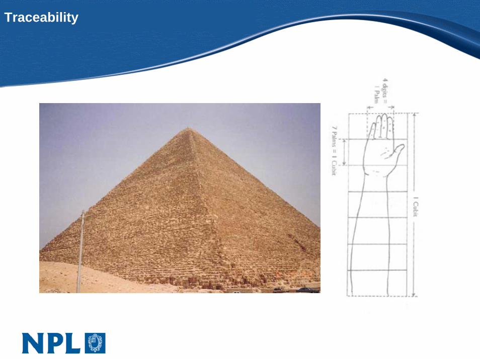
Traceability
Measurement - How?
• Diode arrays • Spectrographs• Broadband filters• Fast amplifiers• Oscilloscopes• Digital camcorders• Power / Energy meters

Spectral Measurement
I/O Box
Trigger: Photodiode and Fast Amplifier

Spectral change within pulse
500.00 550.00 600.00 650.00 700.00 750.00 800.00 850.00 900.00 950.00 1000.00
Wavelength (nm)
Normalised @ 800nm90027006300

Spectral change pulse-to-pulse
650nm Treatment Handpiece IPL Settings: Fluence 24, Pulses 3, Delay 15
505 605 705 805 905 1005
Wavelength (nm)
Pulse 1
Pulse 2
Pulse 3

Cut-off wavelength
585nm and 650nm Spectral Output
505 605 705 805 905 1005
Wavelength (nm)
585nm, Fluence 24
650nm, Fluence 24

Temporal Measurement
ComputerNPLPhotometer
HeadVariable-Gain Low-Noise
High Speed Current Amplifier

Temporal Results
650nm Treatment Head - Photometer MeasurementLumina Settings: Fluence 32, Pulses 4, Delay 15
0
0.2
0.4
0.6
0.8
1
1.2
0.0000 0.0100 0.0200 0.0300 0.0400 0.0500 0.0600 0.0700
Time (s)
Nor
mal
ised

Conclusion
• Time resolved and time averaged spectral results.
• Pulsing shape, duration and delay between pulses.
• Drop in output during pulse train that is due to a fall in the lamp current.
• Lamp current affects the spectral distribution both between pulses and within a pulse.

Conclusion (2)
• Good agreement between the two measurement systems and external data.
• System is limited in its spectral range because of1. Stray light2. Second order radiation3. CCD Quantum Efficiency.
• As yet there is no absolute calibration.

Acknowledgements
• Ewan Eadie & Harry Moseley, Photobiology Unit atNinewells Hospital in Dundee
• Teresa Goodman, Chris Price & the Optical Technologies & Scientific Computing Team at NPL
• Andy Berry & Lynton Lasers• Gerald Cairns & Ciaran McCann (Andor Technology)
• Thank you