IntelliZone2 Installation Manual · 4 INTELLIZONE2 INSTALLATION MANUAL IntelliZone2 Components...
48
Installation Information Damper Installation Thermostat Installation Electrical Startup Procedures Wiring Schematic IM1578EW 05/17 IntelliZone2 Installation Manual Six Zone Capability Comfort Zoning System formation lation stallation dures matic Inte
Transcript of IntelliZone2 Installation Manual · 4 INTELLIZONE2 INSTALLATION MANUAL IntelliZone2 Components...

Installation Information
Damper Installation
Thermostat Installation
Electrical
Startup Procedures
Wiring Schematic
IM1578EW 05/17
Inte
lliZ
on
e2 In
stalla
tio
n M
an
ual
Six Zone Capability
Comfort Zoning System
formation
lation
stallation
dures
matic
Inte

INTELLIZONE2 INSTALLATION MANUAL
Table of Contents
IntelliZone2 Components . . . . . . . . . . . . . . . . . . . . . . . . . . . . . . . . . . . . . . . . . . . . . . . . . . . . . . . . . . . 4
General Installation Information . . . . . . . . . . . . . . . . . . . . . . . . . . . . . . . . . . . . . . . . . . . . . . . . . . . . . 5
Damper Installation . . . . . . . . . . . . . . . . . . . . . . . . . . . . . . . . . . . . . . . . . . . . . . . . . . . . . . . . . . . . . . 6-8
Electrical Wiring. . . . . . . . . . . . . . . . . . . . . . . . . . . . . . . . . . . . . . . . . . . . . . . . . . . . . . . . . . . . . . . . . 9-11
Thermostat Installation. . . . . . . . . . . . . . . . . . . . . . . . . . . . . . . . . . . . . . . . . . . . . . . . . . . . . . . . . . 12-13
IntelliZone2 Configuration . . . . . . . . . . . . . . . . . . . . . . . . . . . . . . . . . . . . . . . . . . . . . . . . . . . . . . . 14-21
Description of Operation - Package Unit . . . . . . . . . . . . . . . . . . . . . . . . . . . . . . . . . . . . . . . . . . . . 22
Blower Data - Package Unit. . . . . . . . . . . . . . . . . . . . . . . . . . . . . . . . . . . . . . . . . . . . . . . . . . . . . 23-26
IntelliZone2 CFM Design. . . . . . . . . . . . . . . . . . . . . . . . . . . . . . . . . . . . . . . . . . . . . . . . . . . . . . . . . . . 27
System Startup and Checkout. . . . . . . . . . . . . . . . . . . . . . . . . . . . . . . . . . . . . . . . . . . . . . . . . . . 27-28
Wiring Schematic. . . . . . . . . . . . . . . . . . . . . . . . . . . . . . . . . . . . . . . . . . . . . . . . . . . . . . . . . . . . . . . . . 29
IntelliZone2 Fault Codes. . . . . . . . . . . . . . . . . . . . . . . . . . . . . . . . . . . . . . . . . . . . . . . . . . . . . . . . . . . 30
Transformer Mounting. . . . . . . . . . . . . . . . . . . . . . . . . . . . . . . . . . . . . . . . . . . . . . . . . . . . . . . . . . . . . 32
Electrical Wiring. . . . . . . . . . . . . . . . . . . . . . . . . . . . . . . . . . . . . . . . . . . . . . . . . . . . . . . . . . . . . . . 33-34
Description of Operation . . . . . . . . . . . . . . . . . . . . . . . . . . . . . . . . . . . . . . . . . . . . . . . . . . . . . . . 35-36
SAH 5 Speed ECM Blower Performance Data Option A . . . . . . . . . . . . . . . . . . . . . . . . . . . . 37-38
Blower Performance Data Option C. . . . . . . . . . . . . . . . . . . . . . . . . . . . . . . . . . . . . . . . . . . . . .39-40
Split Units Wiring Schematic. . . . . . . . . . . . . . . . . . . . . . . . . . . . . . . . . . . . . . . . . . . . . . . . . . . . 41-43
Revision Guide . . . . . . . . . . . . . . . . . . . . . . . . . . . . . . . . . . . . . . . . . . . . . . . . . . . . . . . . . . . . . . . . . . . 45
4
INTELLIZONE2 INSTALLATION MANUAL
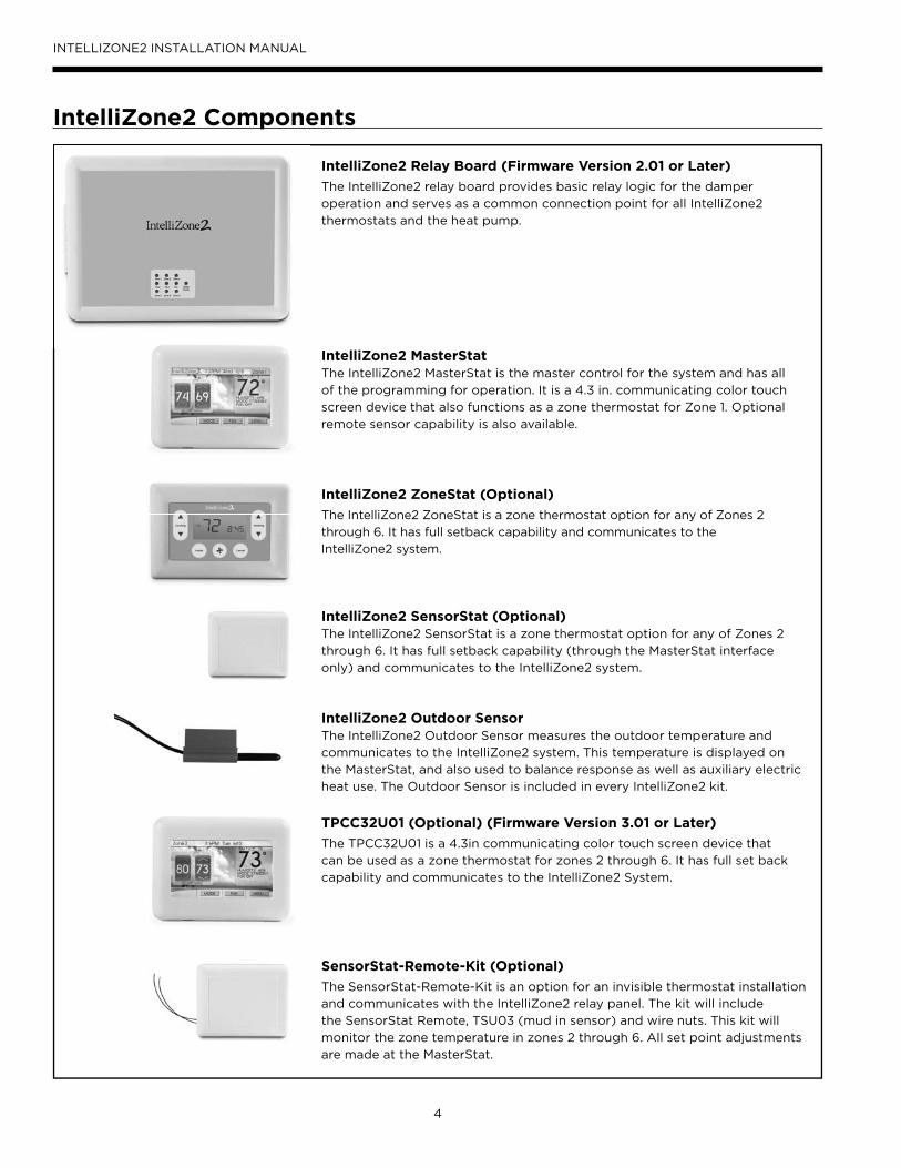
IntelliZone2 Components
IntelliZone2 Relay Board (Firmware Version 2.01 or Later)
The IntelliZone2 relay board provides basic relay logic for the damper
operation and serves as a common connection point for all IntelliZone2
thermostats and the heat pump.
IntelliZone2 MasterStatThe IntelliZone2 MasterStat is the master control for the system and has all
of the programming for operation. It is a 4.3 in. communicating color touch
screen device that also functions as a zone thermostat for Zone 1. Optional
remote sensor capability is also available.
IntelliZone2 ZoneStat (Optional)
The IntelliZone2 ZoneStat is a zone thermostat option for any of Zones 2
through 6. It has full setback capability and communicates to the
IntelliZone2 system.
IntelliZone2 SensorStat (Optional)The IntelliZone2 SensorStat is a zone thermostat option for any of Zones 2
through 6. It has full setback capability (through the MasterStat interface
only) and communicates to the IntelliZone2 system.
IntelliZone2 Outdoor SensorThe IntelliZone2 Outdoor Sensor measures the outdoor temperature and
communicates to the IntelliZone2 system. This temperature is displayed on
the MasterStat, and also used to balance response as well as auxiliary electric
heat use. The Outdoor Sensor is included in every IntelliZone2 kit.
TPCC32U01 (Optional) (Firmware Version 3.01 or Later)
The TPCC32U01 is a 4.3in communicating color touch screen device that
can be used as a zone thermostat for zones 2 through 6. It has full set back
capability and communicates to the IntelliZone2 System.
SensorStat-Remote-Kit (Optional)
The SensorStat-Remote-Kit is an option for an invisible thermostat installation
and communicates with the IntelliZone2 relay panel. The kit will include
the SensorStat Remote, TSU03 (mud in sensor) and wire nuts. This kit will
monitor the zone temperature in zones 2 through 6. All set point adjustments
are made at the MasterStat.
5
INTELLIZONE2 INSTALLATION MANUAL
Safety ConsiderationsInstalling and servicing heating and air conditioning
equipment can be hazardous due to system electrical
components. Only trained and qualifi ed service personnel
should install, repair or service heating and air conditioning
equipment. When working on equipment, observe
precautions in the literature, tags and labels attached to the
unit, and other safety precautions that may apply. Follow all
safety codes. Wear safety glasses and work gloves.
WARNING: Before performing service or maintenance operations on the system, turn off main power switches to the indoor unit. Turn off accessory heater power switch if applicable. Electrical shock could cause serious personal injury.
Delivery InformationWhen the equipment is received, all items should be
carefully checked against the bill of lading to be sure
all crates and cartons have been received. Examine the
contents for shipping damage, removing them from the
cartons if necessary. If any damage is noted, the carrier
should make the proper notation on the delivery receipt,
acknowledging the damage.
General rules to follow when installing a zone system:
CAUTION: When installing the IntelliZone2 in a structure with fossil fuel (oil, gas, propane) appliances, it is important that both supply and return dampers are used in each zone to avoid potential back-drafting of fossil-fueled appliances.
• Up to six zones on variable speed, up to four zones
with dual capacity units (two with single-speed units).
• All dampers should be located as close to the main
trunk as possible to limit the amount of pressurized
trunk line and thus limit air leakage.
• No less than three branch runs in a zone to prevent
a single branch obstruction (curtains or clothes etc.)
from affecting unit airfl ow.
• Insulate and seal around rectangular dampers to
prevent leakage.
• All dampers must be wired with 18-gauge wire.
NOTE: Crimp connections should never be used on
solid conductor wire.
• Ensure that the transformer can handle the power
requirements of the system.
• No more than three dampers per zone.
• Ductboard-mounted dampers should be supported
within six inches of the damper due to the weight and
stress on the ductboard.
General Installation Information
Installation and Design StepsThe IntelliZone2 Comfort Zoning system is to be used only with heat pumps/air handlers equipped with Aurora AXB or AHB controls. If the heat pump/air handler does not have Aurora AXB or AHB controls you must use the IntelliZone2•24V Comfort Zoning system.1. Decide which areas of a home or offi ce will comprise
each of the individual zones. A maximum of six
individual zones (four with dual capacity and two with
single-speed equipment) can be chosen.
2. Calculate loads using software or other
recognized methodology.
3. Use software to determine the equipment size and
performance based on the total heating and cooling
demands of the building, not the sum of the individual
zone demands.
4. Find the peak heating and cooling demands and the
peak cfm required for each of the zones.
5. Determine zone design air fl ow and zone size settings
using IntelliZone2 Design software.
6. Lay out and size the supply air ductwork and dampers.
Care should be taken to avoid under sizing either the
supply air systems, return air systems, or diffusers.
7. Decide where to locate the thermostats.
8. Install the unit and the IntelliZone2 Comfort
Zoning system.
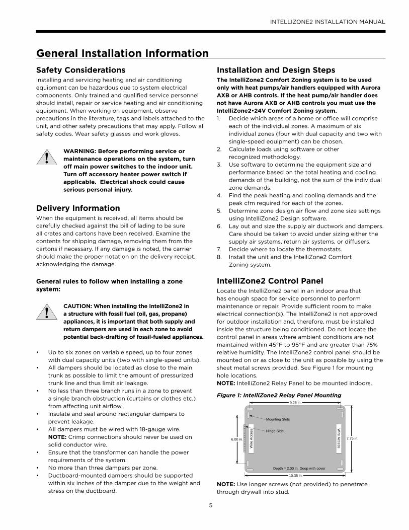
IntelliZone2 Control PanelLocate the IntelliZone2 panel in an indoor area that
has enough space for service personnel to perform
maintenance or repair. Provide sufficient room to make
electrical connection(s). The IntelliZone2 is not approved
for outdoor installation and, therefore, must be installed
inside the structure being conditioned. Do not locate the
control panel in areas where ambient conditions are not
maintained within 45°F to 95°F and are greater than 75%
relative humidity. The IntelliZone2 control panel should be
mounted on or as close to the unit as possible by using the
sheet metal screws provided. See Figure 1 for mounting
hole locations.
NOTE: IntelliZone2 Relay Panel to be mounted indoors.
Figure 1: IntelliZone2 Relay Panel Mounting
NOTE: Use longer screws (not provided) to penetrate
through drywall into stud.
9.25 in.
6.00 in. 7.75 in.
10.35 in.
Hinge Side
Depth = 2.00 in. Deep with cover
Wire A
ccessWire
Acc
ess
Mounting Slots
6
INTELLIZONE2 INSTALLATION MANUAL
Six Zone System Representational Layout
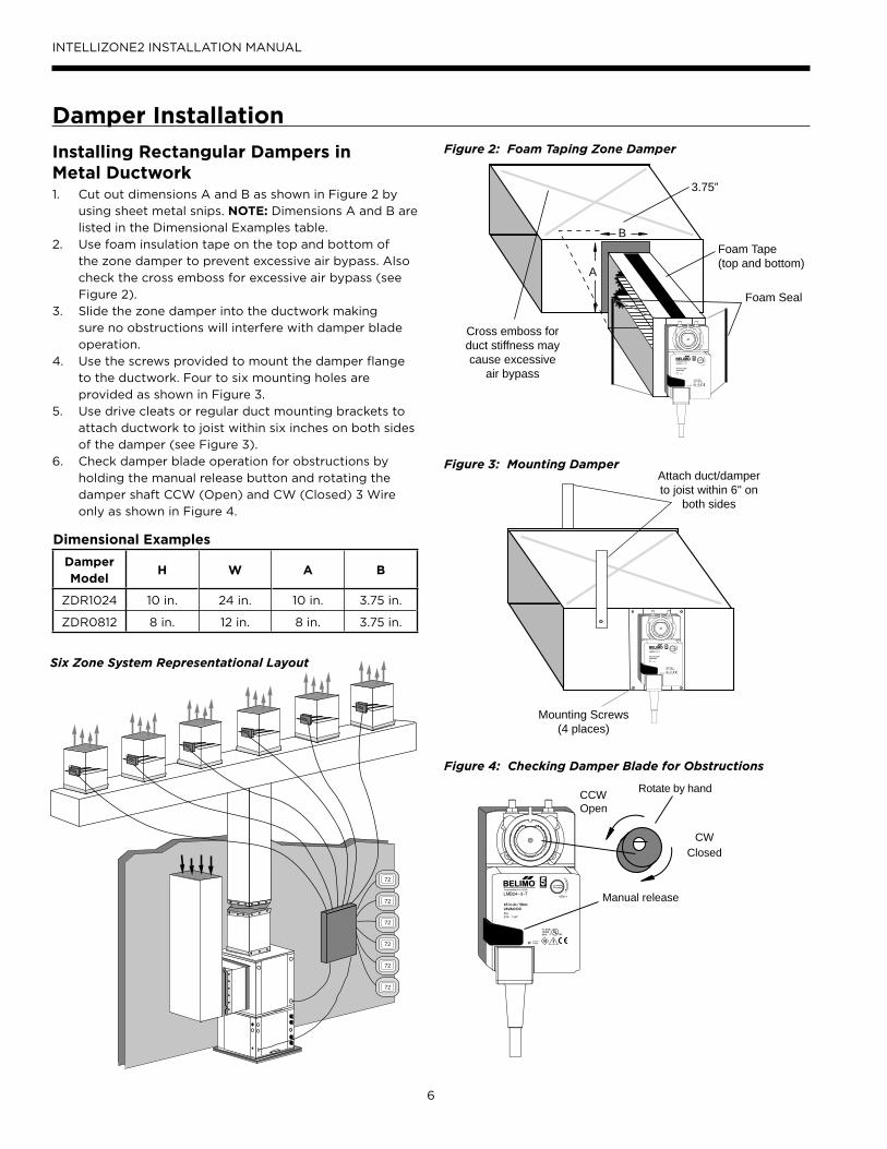
Installing Rectangular Dampers inMetal Ductwork1. Cut out dimensions A and B as shown in Figure 2 by
using sheet metal snips. NOTE: Dimensions A and B are
listed in the Dimensional Examples table.
2. Use foam insulation tape on the top and bottom of
the zone damper to prevent excessive air bypass. Also
check the cross emboss for excessive air bypass (see
Figure 2).
3. Slide the zone damper into the ductwork making
sure no obstructions will interfere with damper blade
operation.
4. Use the screws provided to mount the damper flange
to the ductwork. Four to six mounting holes are
provided as shown in Figure 3.
5. Use drive cleats or regular duct mounting brackets to
attach ductwork to joist within six inches on both sides
of the damper (see Figure 3).
6. Check damper blade operation for obstructions by
holding the manual release button and rotating the
damper shaft CCW (Open) and CW (Closed) 3 Wire
only as shown in Figure 4.
Damper Installation
Manual release
CWClosed
CCWOpen
Rotate by hand
Figure 4: Checking Damper Blade for Obstructions
Cross emboss forduct stiffness maycause excessive
air bypass
Foam Seal
Foam Tape(top and bottom)
A
B
3.75”
Figure 2: Foam Taping Zone Damper
Figure 3: Mounting Damper
Mounting Screws(4 places)
Attach duct/damperto joist within 6" on
both sides
Dimensional Examples
Damper Model
H W A B
ZDR1024 10 in. 24 in. 10 in. 3.75 in.
ZDR0812 8 in. 12 in. 8 in. 3.75 in.
Premier2
72
72
72
72
72
72
C
eCl
7
INTELLIZONE2 INSTALLATION MANUAL
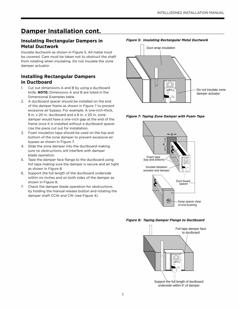
Insulating Rectangular Dampers inMetal DuctworkInsulate ductwork as shown in Figure 5. All metal must
be covered. Care must be taken not to obstruct the shaft
from rotating when insulating. Do not insulate the zone
damper actuator.
Installing Rectangular Dampersin Ductboard1. Cut out dimensions A and B by using a ductboard
knife. NOTE: Dimensions A and B are listed in the
Dimensional Examples table.
2. A ductboard spacer should be installed on the end
of the damper frame as shown in Figure 7 to prevent
excessive air bypass. For example: A one-inch-thick,
8 in. x 20 in. ductboard and a 8 in. x 20 in. zone
damper would have a one-inch gap at the end of the
frame once it is installed without a ductboard spacer.
Use the piece cut out for installation.
3. Foam insulation tape should be used on the top and
bottom of the zone damper to prevent excessive air
bypass as shown in Figure 7.
4. Slide the zone damper into the ductboard making
sure no obstructions will interfere with damper
blade operation.
5. Tape the damper face flange to the ductboard using
foil tape making sure the damper is secure and air tight
as shown in Figure 8.
6. Support the full length of the ductboard underside
within six inches and on both sides of the damper as
shown in Figure 8.
7. Check the damper blade operation for obstructions
by holding the manual release button and rotating the
damper shaft CCW and CW (see Figure 4).
Damper Installation cont.
Do not insulate zonedamper actuator
Duct wrap insulation
Figure 5: Insulating Rectangular Metal Ductwork
A
B
Duct board
Keep spacer clearof end bushing
Foam tape(top and bottom)
Insulate betweenactuator and damper
spacer
Figure 7: Taping Zone Damper with Foam Tape
Foil tape damper faceto ductboard
Support the full length of ductboardunderside within 6” of damper
Figure 8: Taping Damper Flange to Ductboard
8
INTELLIZONE2 INSTALLATION MANUAL
Insulating Rectangular Ductboard/Metal Sleeve Care must be taken not to obstruct the shaft from rotating
when insulating. Do not insulate the zone damper actuator.
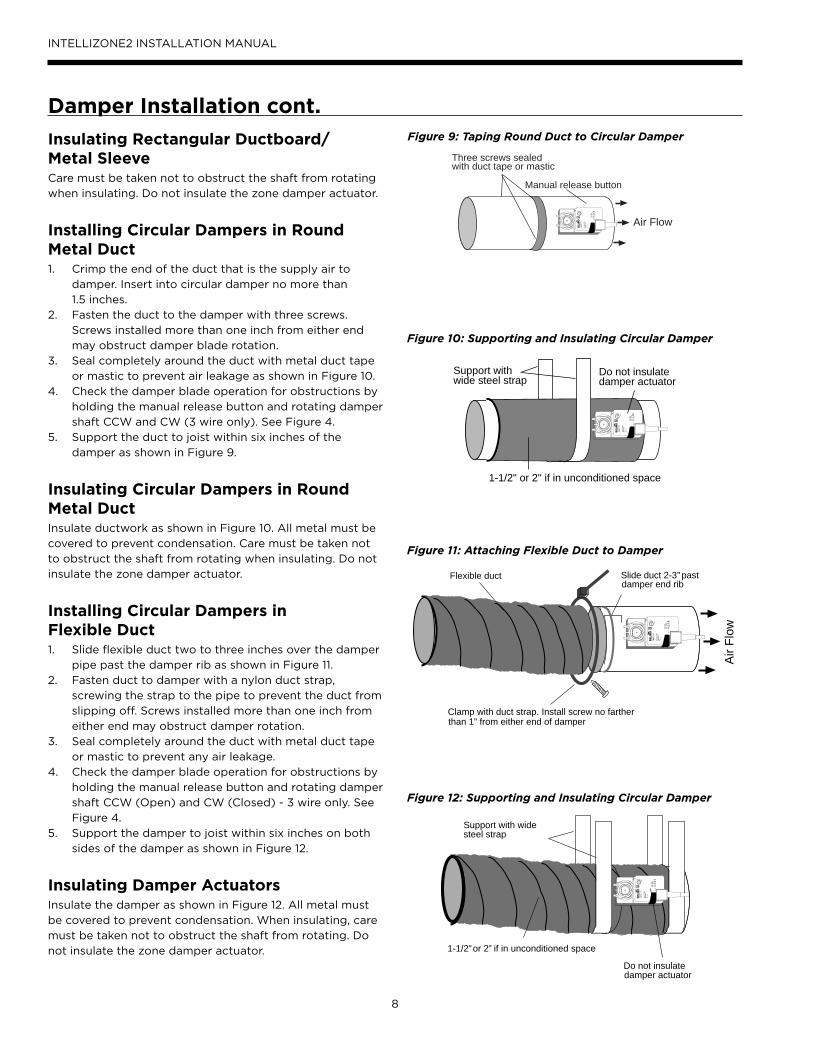
Installing Circular Dampers in Round Metal Duct1. Crimp the end of the duct that is the supply air to
damper. Insert into circular damper no more than
1.5 inches.
2. Fasten the duct to the damper with three screws.
Screws installed more than one inch from either end
may obstruct damper blade rotation.
3. Seal completely around the duct with metal duct tape
or mastic to prevent air leakage as shown in Figure 10.
4. Check the damper blade operation for obstructions by
holding the manual release button and rotating damper
shaft CCW and CW (3 wire only). See Figure 4.
5. Support the duct to joist within six inches of the
damper as shown in Figure 9.
Insulating Circular Dampers in Round Metal DuctInsulate ductwork as shown in Figure 10. All metal must be
covered to prevent condensation. Care must be taken not
to obstruct the shaft from rotating when insulating. Do not
insulate the zone damper actuator.
Installing Circular Dampers inFlexible Duct1. Slide flexible duct two to three inches over the damper
pipe past the damper rib as shown in Figure 11.
2. Fasten duct to damper with a nylon duct strap,
screwing the strap to the pipe to prevent the duct from
slipping off. Screws installed more than one inch from
either end may obstruct damper rotation.
3. Seal completely around the duct with metal duct tape
or mastic to prevent any air leakage.
4. Check the damper blade operation for obstructions by
holding the manual release button and rotating damper
shaft CCW (Open) and CW (Closed) - 3 wire only. See
Figure 4.
5. Support the damper to joist within six inches on both
sides of the damper as shown in Figure 12.
Insulating Damper ActuatorsInsulate the damper as shown in Figure 12. All metal must
be covered to prevent condensation. When insulating, care
must be taken not to obstruct the shaft from rotating. Do
not insulate the zone damper actuator.
Damper Installation cont.
Support with widesteel strap
1-1/2’’ or 2’’ if in unconditioned space
Do not insulatedamper actuator
Figure 12: Supporting and Insulating Circular Damper
Flexible duct
Clamp with duct strap. Install screw no fartherthan 1” from either end of damper
Slide duct 2-3’’ pastdamper end rib
Air
Flow
Figure 11: Attaching Flexible Duct to Damper
Three screws sealedwith duct tape or mastic
Manual release button
Air Flow
Figure 9: Taping Round Duct to Circular Damper
Do not insulatedamper actuator
1-1/2" or 2" if in unconditioned space
Support withwide steel strap
Figure 10: Supporting and Insulating Circular Damper
9
INTELLIZONE2 INSTALLATION MANUAL
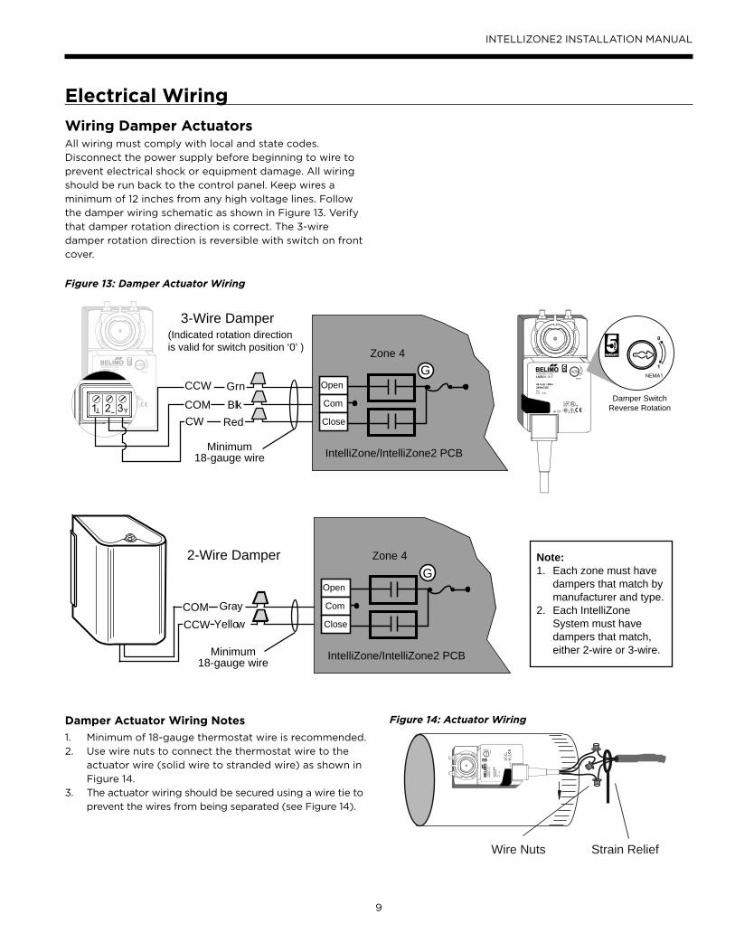
Wiring Damper ActuatorsAll wiring must comply with local and state codes.
Disconnect the power supply before beginning to wire to
prevent electrical shock or equipment damage. All wiring
should be run back to the control panel. Keep wires a
minimum of 12 inches from any high voltage lines. Follow
the damper wiring schematic as shown in Figure 13. Verify
that damper rotation direction is correct. The 3-wire
damper rotation direction is reversible with switch on front
cover.
Figure 13: Damper Actuator Wiring
Electrical Wiring
Wire Nuts Strain Relief
Figure 14: Actuator WiringDamper Actuator Wiring Notes
1. Minimum of 18-gauge thermostat wire is recommended.
2. Use wire nuts to connect the thermostat wire to the
actuator wire (solid wire to stranded wire) as shown in
Figure 14.
3. The actuator wiring should be secured using a wire tie to
prevent the wires from being separated (see Figure 14).
3-Wire Damper
Zone 4
Com
Open
Close
G
Minimum18-gauge wire
(Indicated rotation directionis valid for switch position ‘0’ )
BlkCOM
GrnCCW
RedCW
IntelliZone/IntelliZone2 PCB
2-Wire Damper
Minimum18-gauge wire
Zone 4
IntelliZone/IntelliZone2 PCB
Com
Open
Close
G
COM Gray
CCW Yellow
Damper SwitchReverse Rotation
Note:1. Each zone must have
dampers that match bymanufacturer and type.
2. Each IntelliZone System must have dampers that match, either 2-wire or 3-wire.
10
INTELLIZONE2 INSTALLATION MANUAL
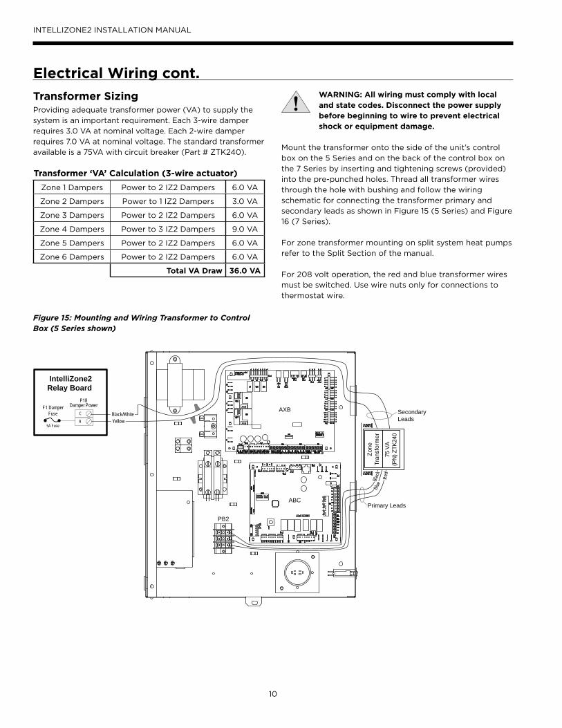
WARNING: All wiring must comply with local and state codes. Disconnect the power supply before beginning to wire to prevent electrical shock or equipment damage.
Mount the transformer onto the side of the unit’s control
box on the 5 Series and on the back of the control box on
the 7 Series by inserting and tightening screws (provided)
into the pre-punched holes. Thread all transformer wires
through the hole with bushing and follow the wiring
schematic for connecting the transformer primary and
secondary leads as shown in Figure 15 (5 Series) and Figure
16 (7 Series).
For zone transformer mounting on split system heat pumps
refer to the Split Section of the manual.
For 208 volt operation, the red and blue transformer wires
must be switched. Use wire nuts only for connections to
thermostat wire.
Transformer SizingProviding adequate transformer power (VA) to supply the
system is an important requirement. Each 3-wire damper
requires 3.0 VA at nominal voltage. Each 2-wire damper
requires 7.0 VA at nominal voltage. The standard transformer
available is a 75VA with circuit breaker (Part # ZTK240).
Transformer ‘VA’ Calculation (3-wire actuator)
Zone 1 Dampers Power to 2 IZ2 Dampers 6.0 VA
Zone 2 Dampers Power to 1 IZ2 Dampers 3.0 VA
Zone 3 Dampers Power to 2 IZ2 Dampers 6.0 VA
Zone 4 Dampers Power to 3 IZ2 Dampers 9.0 VA
Zone 5 Dampers Power to 2 IZ2 Dampers 6.0 VA
Zone 6 Dampers Power to 2 IZ2 Dampers 6.0 VA
Total VA Draw 36.0 VA
Electrical Wiring cont.
Figure 15: Mounting and Wiring Transformer to Control Box (5 Series shown)
R
C
P18Damper PowerF1 Damper
Fuse Black/White
5A Fuse
IntelliZone2Relay Board
Primary Leads
SecondaryLeads
Zone
Tran
sfor
mer
75 V
A(P
N) Z
TK24
0
Black
Blue
Red
Yellow
AXB
ABC
PB2

11
INTELLIZONE2 INSTALLATION MANUAL
Wiring IntelliZone2 to the UnitWARNING: All wiring must comply with local and state codes. Disconnect the power supply before beginning to wire to prevent electrical shock or equipment damage.
Follow the wiring schematic in Figure 17 for unit control
connections. Strip the wires back 1/4 inch (longer strip
lengths may cause shorts) and insert the thermostat wires
into the unit’s connector as shown in Figure 17. Tighten
the screws to ensure tight connections. Use a minimum of
18-gauge thermostat wire for connections.
For wiring IntelliZone2 to split system heat pumps refer to
the Split Section of the manual.
Figure 16: Mounting and Wiring Transformer to Control Box (7 Series shown)
Figure 17: IntelliZone2 to 5 or 7 Series Control Wiring
Electrical Wiring cont.
A+RCB-
P17
– H
eat P
ump
+RC-P
7 - Z
one
Aurora AXB
AuroraABC
5 or 7 Series Heat Pump
R+
-C
Harness supplied with IntelliZone2then wire nut to stat wire
AID Tool
IntelliZone2Relay Board
Zone Transformer(mounted on backside
of control box)
R
C
P18Damper Power F1 Damper
Fuse
5A Fuse
IntelliZone2Relay Board
Black/WhiteYellow
BlackBlueRed
SecondaryLeads
Primary
AXB
ABC
PS
Leads
Note: The harness supplied with IntelliZone2 is designed to plug into the Aurora AXB P7-Zone connection only. The IntelliZone2 cannot be connected to P7 on the ABC board.
12
INTELLIZONE2 INSTALLATION MANUAL
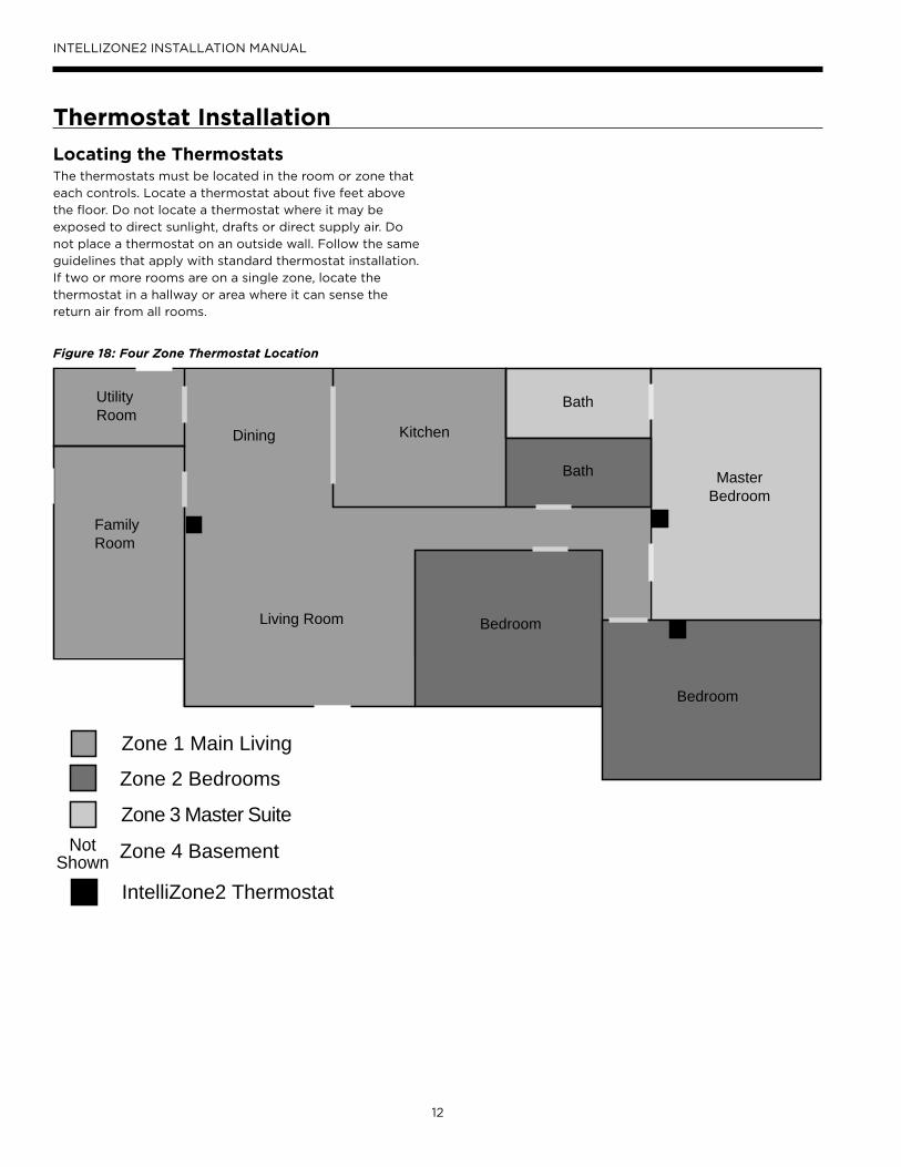
Locating the ThermostatsThe thermostats must be located in the room or zone that
each controls. Locate a thermostat about five feet above
the floor. Do not locate a thermostat where it may be
exposed to direct sunlight, drafts or direct supply air. Do
not place a thermostat on an outside wall. Follow the same
guidelines that apply with standard thermostat installation.
If two or more rooms are on a single zone, locate the
thermostat in a hallway or area where it can sense the
return air from all rooms.
Thermostat Installation
Figure 18: Four Zone Thermostat Location
MasterBedroom
Bath
Bath
Bedroom
Bedroom
Kitchen
Living Room
UtilityRoom
Dining
Zone 2 Bedrooms
Zone 1 Main Living
Zone 3 Master Suite
Zone 4 BasementNotShown
FamilyRoom
IntelliZone2 Thermostat
13
INTELLIZONE2 INSTALLATION MANUAL
Thermostat Installation cont.
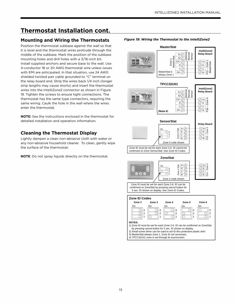
Mounting and Wiring the ThermostatsPosition the thermostat subbase against the wall so that
it is level and the thermostat wires protrude through the
middle of the subbase. Mark the position of the subbase
mounting holes and drill holes with a 3/16-inch bit.
Install supplied anchors and secure base to the wall. Use
4-conductor 18 or 20 AWG thermostat wire unless issues
with EMI are anticipated. In that situation, use 24 AWG
shielded twisted pair cable grounded to “C” terminal on
the relay board end. Strip the wires back 1/4 inch (longer
strip lengths may cause shorts) and insert the thermostat
wires into the IntelliZone2 connector as shown in Figure
19. Tighten the screws to ensure tight connections. The
thermostat has the same type connectors, requiring the
same wiring. Caulk the hole in the wall where the wires
enter the thermostat.
NOTE: See the instructions enclosed in the thermostat for
detailed installation and operation information.
Cleaning the Thermostat DisplayLightly dampen a clean non-abrasive cloth with water or
any non-abrasive household cleaner. To clean, gently wipe
the surface of the thermostat.
NOTE: Do not spray liquids directly on the thermostat.
Figure 19: Wiring the Thermostat to the IntelliZone2
A+RCB- P
14 –
Zon
e 4
A+RCB- P
15 –
Zon
e 5
A+RCB-Zo
ne 4
Sta
t
On32 1
Zone 4 code shown
A+RCB-Zo
ne 5
Sta
tOn32 1
Zone 5 code shown
ZoneStat
SensorStat
Zone ID must be set for each Zone 2-6. ID can beconfirmed on ZoneStat by pressing cancel button for
5 sec. ID shown on display. See Zone ID Codes.
Zone ID must be set for each Zone 2-6. ID cannot beconfirmed on Zone SensorStat. See Zone ID Codes.
Relay Board
A+
R
C
B- P11
– Z
one
1M
aste
rSta
tDX+
R
C
DX-
Zone
1M
aste
rSta
t
MasterStat isalways Zone 1
S1
S2
IntelliZone2Relay Board
A+
R
C
B- P16
– Z
one
6DX+
R
C
DX-
S1
S2
Opt
iona
lR
emot
eS
enso
r
IntelliZone2Relay Board
MasterStat
TPCC32U01
On
32 1
On
32 1
On
32 1
Zone 4 Zone 5Zone 3On
32 1
Zone 2On
32 1
Zone 6Zone ID Codes
NOTES:1) Zone ID must be set for each Zone 2-6. ID can be confirmed on ZoneStat by pressing cancel button for 5 sec. ID shown on display.2) Small screw driver can be used to set ID thru protective plastic skin!3) MasterStat always Zone 1. Zone ID not necessary. 4) TPCC32U01 zone is set through its touchscreen.
(Note 4)
Opt
iona
lR
emot
eS
enso
r
14
INTELLIZONE2 INSTALLATION MANUAL
IntelliZone2 Confi guration
Aurora System and Communication Configuration of IntelliZone2 Aurora Communication BasicsThe Aurora Control functions around the concept of modularity and intercommunications between these boards. The communication is a 4 wire ModBus protocol. ModBus protocol is an open source protocol becoming more popular with equipment manufacturers for use in HVAC equipment. The Aurora has one ‘bus’ for the ABC, AXB, AHB, AWL, VS Drive, EEV, and thermostats. The AID Tool only plugs into the ABC AID Tool port, SAH Air Handler AID Tool port or the AWL (RJ style connector) and will not work at any other location. The AXB has 3 other independent ports for differing protocols; for IntelliZone2, ClimateTalk Components, and Communicating ECM blower motors. None of these ports comply with the ModBus protocol set up for the rest of the Aurora system.
The ModBus communication is accomplished within the cabinet using shielded and ground cabling. This shield is most important in 7 Series applications where the VS Drive component, by its very nature, emits electro-magnetic interference and can interfere with ModBus communications. Round ferrite ‘donuts’ can be observed at various locations to aid in cleaning the communication lines. Each line is comprised of an R (+24VAC), C (common) and a ‘+’ and ‘-‘ communication line. At times the ‘R’ and ‘C’ lines may not be connected or needed. The terminals marked ‘+’ and ‘-‘ should not be switched, although damage may not occur to the boards, communication is not possible. The communication voltage and current are small therefore 24 awg wire is adequate for these communication lines and a shield is not required but recommended in high EMI environments.
An extra ‘expansion’ connector is available for connecting other devices onto the main ABC ModBus.
A small LED is located next to each of the communication ports to aid in evaluating active communication at that specific port. This is true for each board. The blinking indicates transmission or receiving communication activity.
Configuring the Aurora for the IntelliZone2 'Adding' the IntelliZone2 to the Aurora system can be accomplished using the AID Tool via the 'Config Aurora' screen and scrolling to IntelliZone2 selecting and adding. As always a 'Y' in the communication column shows that communication is OK. This will initiate communication between the IntelliZone2 system and the Aurora AXB/ABC.
Software VersionsSoftware versions of the IntelliZone2 MasterStat can be found in the startup screen or in the AID Tool Aurora Config screen. The software version on the TPCC32U01 can be found on the settings screen. Firmware can be uploaded to the MasterStat or TPCC32U01 via the USB port on the thermostat. Consult your local WaterFurnace representative or tech service for details.
NOTE: When updating the firmware on the TPCC32U01 each thermostat will need to be updated. Firmware for the MasterStat and TPCC32U01 are NOT the same. After the TPCC32U01 firmware is updated to v3.01, or later, go into the installers screen and select restore defaults. If you do not restore the default setting the zone will not be displayed on the TPCC32U01.
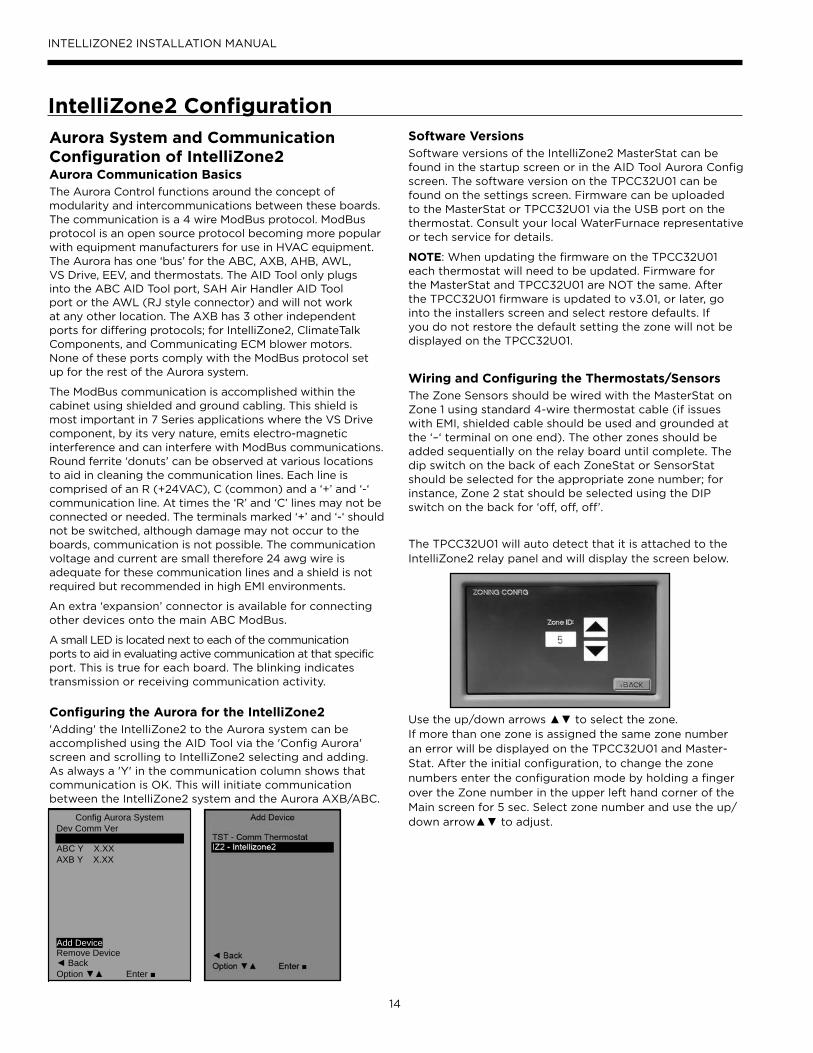
Wiring and Configuring the Thermostats/SensorsThe Zone Sensors should be wired with the MasterStat on Zone 1 using standard 4-wire thermostat cable (if issues with EMI, shielded cable should be used and grounded at the ‘–‘ terminal on one end). The other zones should be added sequentially on the relay board until complete. The dip switch on the back of each ZoneStat or SensorStat should be selected for the appropriate zone number; for instance, Zone 2 stat should be selected using the DIP switch on the back for ‘off, off, off’.
The TPCC32U01 will auto detect that it is attached to the IntelliZone2 relay panel and will display the screen below.
Use the up/down arrows ▲▼ to select the zone.If more than one zone is assigned the same zone number an error will be displayed on the TPCC32U01 and Master-Stat. After the initial confi guration, to change the zone numbers enter the confi guration mode by holding a fi nger over the Zone number in the upper left hand corner of the Main screen for 5 sec. Select zone number and use the up/down arrow▲▼ to adjust.Config Aurora System
Dev Comm Ver ABC Y X.XX
AXB Y X.XX
Add Device Remove Device
Back
Option Enter
15
INTELLIZONE2 INSTALLATION MANUAL
A+RCB- P
14 –
Zon
e 4
A+RCB- P
15 –
Zon
e 5
A+RCB-Zo
ne 4
Sta
t
On32 1
Zone 4 code shown
A+RCB-Zo
ne 5
Sta
tOn32 1
Zone 5 code shown
ZoneStat
SensorStat
Zone ID must be set for each Zone 2-6. ID can beconfirmed on ZoneStat by pressing cancel button for
5 sec. ID shown on display. See Zone ID Codes.
Zone ID must be set for each Zone 2-6. ID cannot beconfirmed on Zone SensorStat. See Zone ID Codes.
Relay Board
A+
R
C
B- P16
– Z
one
6DX+
R
C
DX-
S1
S2
Opt
iona
lR
emot
eS
enso
r
IntelliZone2Relay Board
TPCC32U01
On
32 1
On
32 1
On
32 1
Zone 4 Zone 5Zone 3On
32 1
Zone 2On
32 1
Zone 6Zone ID Codes
NOTES:1) Zone ID must be set for each Zone 2-6. ID can be confirmed on ZoneStat by pressing cancel button for 5 sec. ID shown on display.2) Small screw driver can be used to set ID thru protective plastic skin!3) MasterStat always Zone 1. Zone ID not necessary. 4) TPCC32U01 zone is set through its touchscreen.
(Note 4)
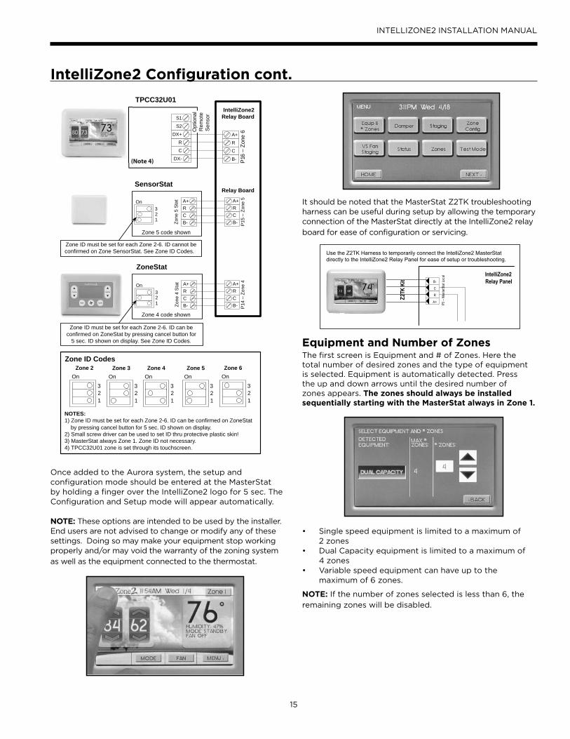
Once added to the Aurora system, the setup and configuration mode should be entered at the MasterStat by holding a finger over the IntelliZone2 logo for 5 sec. The Configuration and Setup mode will appear automatically.
NOTE: These options are intended to be used by the installer. End users are not advised to change or modify any of these settings. Doing so may make your equipment stop workingproperly and/or may void the warranty of the zoning system
as well as the equipment connected to the thermostat.
It should be noted that the MasterStat Z2TK troubleshooting harness can be useful during setup by allowing the temporary connection of the MasterStat directly at the IntelliZone2 relay
board for ease of configuration or servicing.
Equipment and Number of ZonesThe first screen is Equipment and # of Zones. Here the total number of desired zones and the type of equipment is selected. Equipment is automatically detected. Press the up and down arrows until the desired number of zones appears. The zones should always be installed sequentially starting with the MasterStat always in Zone 1.
• Single speed equipment is limited to a maximum of2 zones
• Dual Capacity equipment is limited to a maximum of4 zones
• Variable speed equipment can have up to the maximum of 6 zones.
NOTE: If the number of zones selected is less than 6, the
remaining zones will be disabled.
P3 –
Mast
erSt
at Lo
cal
C
B-
A+
RZ2TK
Kit
IntelliZone2 Relay Panel
Use the Z2TK Harness to temporarily connect the IntelliZone2 MasterStatdirectly to the IntelliZone2 Relay Panel for ease of setup or troubleshooting.
IntelliZone2 Confi guration cont.

16
INTELLIZONE2 INSTALLATION MANUAL
DamperThe Damper screen allows the selection of either 2 wire
(spring open) or 3 wire (power open/power closed) type.
StagingStaging allows custom selection of staging for cooling and heating, independently.
The IntelliZone2 system allows separate staging options for cooling and heating. There are four options for each mode which are explained below. As an example, staging for cooling can be set for ‘Normal’ while staging for heating is set for ‘Faster2’. Allowing heating and cooling staging to be independent of each other will provide better comfort all year long. Once the compressor call has been initiated by a zone, the compressor will be upstaged using one of the four staging options.
Single and Dual Staging
Normal - This “as shipped” mode will upstage the blower
and compressor normally.
Quicker - This mode will upstage the blower, compressor
and auxiliary electric heat more expediently than “normal”
mode for increased comfort.
Faster1 - This mode allows for a timed element in compressor (heating and cooling) and electric heat (heating) upstaging in 45% and 70% zones for situations in which ‘Quicker’ upstaging is inadequate. If the heat pump is already operating in first stage and a 45% or 70% zone has had a heating or cooling demand for 30 continuous minutes then second stage will be activated. For heating, if after another continuous 30 minutes the H3 demand is still present from a 45% or 70% zone, third stage will be activated until the zone call is reduced to a H2. Airflow will increase with compressor staging/EH during this period. For heating, if the heat pump is already operating in second stage and a 45% or 70% zone has had a demand for 30 continuous minutes then third stage will be activated until the demand is reduced to H2. Airflow will be increased to EH selection during this period.
Faster2 - This mode allows for a timed element in compressor (heating and cooling) and electric heat (heating) upstaging in 45% and 70% zones for situations in
which ‘Faster 1’ upstaging is inadequate. If the heat pump is already operating in first stage and a 45% or 70% zone has had a heating or cooling demand for 15 continuous minutes then second stage will be activated. For heating, if after another continuous 15 minutes the H3 demand is still present from a 45% or 70% zone, third stage will be activated until the zone call is reduced to a H2. Airflow will increase with compressor staging/EH during this period. For heating, if the heat pump is already operating in second stage and a 45% or 70% zone has had a demand for 15 continuous minutes then third stage will be activated until the demand is reduced to H2. Airflow will be increased to EH selection during this period.
Variable Speed StagingFor heating in all staging options below, the total of the zone demands will determine when auxiliary heat is energized which could be anywhere from compressor speed 9 to speed 12. If auxiliary heat is energized while on compressor speed 9-11 the compressor speed automatically increases to speed 12. Airflow will increase with
compressor speed/EH during this period.
Normal - This “as shipped” mode will upstage the blower
and variable speed compressor normally.
Quicker - This mode will upstage the blower, compressor and auxiliary electric heat more expediently than “normal” mode for increased comfort. Generally the compressor will
be upstaged 1 extra speed more than normal.
Faster1 - This mode allows for a timed element in compressor and electric heat upstaging in 45% and 70% zones for situations in which quicker staging is not meeting demand. When an H3 (heating) or C2 (cooling) demand is initially received the compressor will upstage two speeds more than normal. After 15 continuous minutes of an H3 or C2 demand the compressor will upstage one more compressor speed and will continue to upstage one compressor speed with every 15 minutes of a continuous H3 or C2 demand until auxiliary electric heat is energized for heating or C2 or maximum compressor speed for
cooling.
Faster2 - This mode also allows for a timed element in compressor and electric heat upstaging in 45% and 70% zones for situations in which Faster1 is not meeting heating demand. When an H3 (heating) or C2 (cooling) demand is initially received the compressor will upstage two speeds more than normal. After 15 continuous minutes of an H3
or C2 demand the compressor will upstage two more
compressor speeds and will continue to upstage two compressor speeds with every 15 minutes of a continuous H3 demand until auxiliary electric heat is energized or maximum compressor speed for cooling.
IntelliZone2 Confi guration cont.
17
INTELLIZONE2 INSTALLATION MANUAL
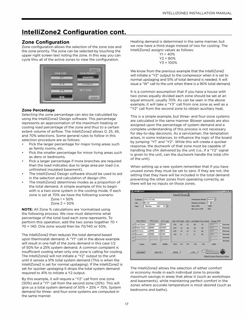
Zone ConfigurationZone configuration allows the selection of the zone size and the zone priority. The zone can be selected by touching the upper right screen text noting the zone. In this way you can cycle thru all of the active zones to view the configuration.
Zone PercentageSelecting the zone percentage can also be calculated by using the IntelliZone2 Design software. This percentage represents an approximation of the maximum heating or cooling load percentage of the zone and thus to a certain extent volume of airflow. The IntelliZone2 allows 0, 25, 45, and 70% selections. Some general rules to follow in this selection procedure are as follows:• Pick the larger percentage for major living areas such
as family rooms, etc.• Pick the smaller percentage for minor living areas such
as dens or bedrooms.• Pick a larger percentage if more branches are required
than the load indicates due to large area per load (i.e. unfinished insulated basement).
• The IntelliZone2 Design software should be used to aid in the selection and calculation of design cfm.
• The IntelliZone2 determines modes as a proportion of the total demand. A simple example of this to begin with is a two-zone system in the cooling mode. If each zone is set at 70% we have the following scenario:
Zone 1 = 50% Zone 2 = 50%
NOTE: All Zone % calculations are ‘normalized using the following process: We now must determine what percentage of the total load each zone represents. To perform this operation, add the two zones together 70 + 70 = 140. One zone would then be 70/140 or 50%.
The IntelliZone2 then reduces the total demand based upon thermostat demand. A “Y1” call in the above example will result in one half of the zone demand in this case 1/2 of 50% for a 25% system demand. A common complaint is insufficient cooling when only one zone is calling for cooling. The IntelliZone2 will not initiate a “Y2” output to the unit until it senses a 51% total system demand (This is when the IntelliZone2 is set for normal upstaging). If the IntelliZone2 is set for quicker upstaging it drops the total system demand required to 41% to initiate a Y2 output.
By this example, it will require a “Y2” call from one zone (50%) and a “Y1” call from the second zone (25%). This will give us a total system demand of 50% + 25% = 75%. System demand for three- and four-zone systems are computed in the same manner.
Heating demand is determined in the same manner, but we now have a third stage instead of two for cooling. The IntelliZone2 assigns values as follows: Y1 = 40% Y2 = 80% Y3 = 100%
We know from the previous example that the IntelliZone2 will initiate a “Y2” output to the compressor when it is set to normal upstaging and 51% of total demand is needed. It will issue a “W” call to the unit when there is a 90% total demand.
It is a common assumption that if you have a house with two zones equally divided each zone should be set at an equal amount, usually 70%. As can be seen in the above example, it will take a “Y3” call from one zone as well as a “Y2” call from the second zone to obtain auxiliary heat.
This is a simple example, but three- and four-zone systems are calculated in the same manner. Blower speeds are also assigned upon the percentage of system demand and a complete understanding of this process is not necessary for day-to-day decisions. As a serviceman, the temptation arises, in some instances, to influence the logic of the board by jumping “Y1” and “Y2”. While this will create a quicker response, the ductwork of that zone must be capable of handling the cfm delivered by the unit (i.e., if a “Y2” signal is given to the unit, can the ductwork handle the total cfm of the unit).
When setting up a new system remember that if you have unused zones they must be set to zero. If they are not, the setting that they have will be included in the total demand preventing the other zones from operating correctly, as there will be no inputs on those zones.
The IntelliZone2 allows the selection of either comfort or economy mode in each individual zone to provide maximum savings in areas that allow it (such as workshops and basements), while maintaining perfect comfort in the zones where accurate temperature is most desired (such as
bedrooms and baths).
IntelliZone2 Confi guration cont.

18
INTELLIZONE2 INSTALLATION MANUAL
IntelliZone2 Confi guration cont.Zone Priority
Comfort Mode - A single zone call (Y1) for conditioning
will engage the compressor and allow a minimal set point
variation, thus providing ultimate comfort.
Economy Mode - A single zone call (Y1) for conditioning
will be ignored by the IntelliZone2 until either a Y2 call
is initiated from the same zone or another zone calls for
conditioning (Y1). This allows a slightly greater set point
variation than in comfort mode. This setting prevents
less important zones from energizing the compressor
unless it is really needed, thus saving money. As a bonus
in this mode, upon a Y1 call, the IntelliZone2 may try to
precondition the zone with return air from other zones
already satisfied and, in some cases, can preclude the need
for energizing the compressor.
Variable Speed Fan Staging - Variable Speed Fan Staging
allows the ability to expand the blower levels. Options
are Normal and Expanded. There are three airflow speeds
assigned to a compressor speed and the airflow level is
determined by the fan demand total zone %. Normal is
the recommended airflow level. Selecting Expanded will
increase the highest airflow level by one level and decrease
the lowest airflow level by one level from Normal. Not
available for single speed or dual capacity models.
Zones - Displays the inputs that the Intellizone2 is
receiving.
Status - Displays the outputs that the IntelliZone2 is
sending to the equipment.
Test Mode - In Test mode ‘Central Zone’ mode can be
selected. In Central mode all dampers are opened and
thermostat readings are taken ONLY from the Zone 1
MasterStat. This will approximate operation without a zone
system (all dampers open and IntelliZone2 MasterStat
temperature control) and can be useful during initial
construction of the home or during service etc.
Also in ‘Central Zone’ mode each damper can be
individually cycled off/on to verify operation during
Installation or service. It should be noted that the
MasterStat Z2TK troubleshooting harness can be useful
here by allowing the temporary connection of the
MasterStat directly at the IntelliZone2 relay board for ease
of configuration or servicing.
Thermostat Type
NORMAL/DUAL FUEL Normal - used for normal operation Dual Fuel - used on dual fuel systems; needs outdoor sensor to lockout dual fuel
19
INTELLIZONE2 INSTALLATION MANUAL
IntelliZone2 Confi guration cont.Dual Fuel (Single Speed/Dual Capacity) - When Dual Fuel
is selected for ‘Thermostat Type’ and a ‘W’ call is present
operation will be as follows:
1. The temperature will be controlled by the MasterStat
while other zones are ignored.
2. All zone dampers will open, Y1, Y2, G, W outputs shall
run for 60 seconds. After 60 seconds Y1 and Y2 will be
dropped and output only W and G (if Fan with Heat
Option is selected otherwise G will be dropped).
3. There will be a two minute minimum run time once
Dual Fuel operation has been entered, regardless if
MasterStat heat call has been satisfied.
4. Once the two minute minimum run time expires and
the ‘W’ call is satisfied at the MasterStat then Dual Fuel
operation will be terminated. There will be no down
staging.
5. Once Dual Fuel operation is terminated all zone
dampers will close.
6. There will be a 4 minute time delay once Dual Fuel
operation is terminated before compressor operation
for cooling or heating may begin.
Dual Fuel (Variable Speed) - When Dual Fuel is selected
for ‘Thermostat Type’ and a ‘W’ call is present operation
will be as follows.
1. The temperature will be controlled by the MasterStat
while other zones are ignored.
2. All zone dampers will open, the current compressor
speed, G and W outputs shall run for 60 seconds. After
60 seconds the compressor will be stopped and output
only W and G (if Fan with Heat Option is selected
otherwise G will be dropped).
3. There will be a two minute minimum run time once
Dual Fuel operation has been entered, regardless if
MasterStat heat call has been satisfied.
4. Once the two minute minimum run time expires and
the ‘W’ call is satisfied at the MasterStat then Dual Fuel
operation will be terminated. There will be no down
staging.
5. Once Dual Fuel operation is terminated all zone
dampers will close.
6. There will be a 4 minute time delay once Dual Fuel
operation is terminated before compressor operation
for cooling or heating may begin.
Fan with Heat Option (Dual Fuel Applications) - Options
are ON or OFF. This selection determines whether G (fan)
output is to be ON or OFF when W (auxiliary heat) output
is ON.
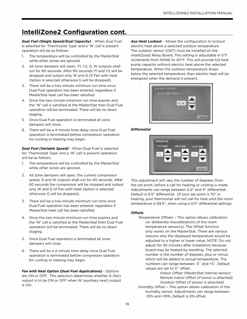
Aux Heat Lockout - Allows the configuration to lockout
electric heat above a selected outdoor temperature.
The outdoor sensor (OAT) must be installed on the
IntelliZone2 Relay Board. This setting is adjustable in 5°F
increments from NONE to 40°F. This will provide full heat
pump capacity without electric heat above the selected
temperature. When the outdoor temperature drops
below the selected temperature, then electric heat will be
energized when the demand is present.
Differential
This adjustment will vary the number of degrees, from
the set point, before a call for heating or cooling is made.
Adjustments can range between 0.2° and 4° differential.
Default is 0.5° differential. (If your set point is 70° in
heating, your thermostat will not call for heat until the room
temperature is 69.5°, when using a 0.5° differential setting).
OffsetsTemperature Offsets – This option allows calibration
(or deliberate miscalibration) of the room
temperature sensor(s). The Offset function
only works on the MasterStat. There are various
reasons why the displayed temperature would be
adjusted to a higher or lower value. NOTE: Do not
adjust for 30 minutes after installation because
board may be heated by handling. The selected
number is the number of degrees, plus or minus,
which will be added to actual temperature. The
numbers can range between -5˚ and +5˚. Default
values are set to 0˚ offset.
Indoor Offset (MasterStat internal sensor)Remote Indoor Offset (if sensor is attached)
Outdoor Offset (if sensor is attached)Humidity Offset – This option allows calibration of the
humidity sensor. Adjustments can range between
-10% and +10%. Default is 0% offset.

20
INTELLIZONE2 INSTALLATION MANUAL
IntelliZone2 Confi guration cont.Humidity
Humidify - Turns on the H output when the room humidity is below the set point and there is an active heating call.
Dehumidify – Turns on the DH output when the room humidity is above the set point and the MODE is set to COOL or AUTO when Cool was the last mode run.
-Turns on Active Dehumidification (VS systems)
Both – HUMIDIFY operates in the HEAT mode and DEHUMIDIFY operates in COOL mode.
NONE – Neither is active.
Temperature Sensors - Allows the configuration of the
remote sensor to be remote only, average of remote and
internal, or no remote sensor. Allows the configuration of
the outdoor sensor to be zone panel, MasterStat, or no
outdoor sensor. Because IntelliZone2 ships standard with
an outdoor sensor this option needs to be selected.NOTE: LAS on IntelliZone2 relay board = OAT
Accessories -
Each of these options has settings for Cumulative Run Time
and Calendar Time. Messages will flash at the top of the
Main screen when these events are met to alert the owner
that it is time service these options.
Air Filter - Cumulative Run Time default is 1000 hours
and Calendar Time is 3 months. Values can range
from NONE-2500 hours for Cumulative Run Time
(in 100 hour increments), or Calendar Time can be
set to NONE to 12 months (in 3 month increments).
Humidifier - Cumulative Run Time default is NONE
hours (OFF) and Calendar Time is NONE Values
can range from NONE, 400-2500 hours for
Cumulative Run Time (in 100 hour increments), or
Calendar Time can be set to NONE, to 12 months
(in 3 month increments).
UV Lamp - Cumulative Run Time default is NONE
hours (OFF) and Calendar Time is NONE. Values
can range from NONE, 400-3600 hours for
Cumulative Run Time (in 100 hour increments), or
Calendar Time can be set to NONE to 48 months
(in 3 month increments).
Air Cleaner - Cumulative Run Time default is 0 hours
(NONE) and Calendar Time is NONE. Values can
range from NONE, 400-2500 hours for Cumulative
Run Time (in 100 hour increments), or Calendar
Time can be set to NONE to 12 months (in 3 month
increments
Dealer Information - Allows the input of the dealer name,
phone, address, e-mail and website. Simply press the
screen segment where you want to enter information and a
keypad will appear.
Fault Status - Shows the last 10 IntelliZone2 system Faults
(heat pump fault history is displayed at the heat pump on
the AID Tool). The faults can be cleared or refreshed from
this screen.
Restore Defaults - This will allow you to revert to the
factory default settings.
Restart Thermostat/Upgrade Software - This allows a
convenient way to restart the thermostat or upload the
latest software using the USB port without killing power to
the whole system.
USB - Allows the import and export of data using the USB port.
Importation of: Installer settings, User Settings, Program,
Dealer Details
Exportation of: Installer settings, User Settings, Program,
Dealer Details
Data Logging - Allows the USB thumb drive to record the data
from the zoning system every 5 seconds.
F°/C° - Allows selection of either Fahrenheit or Celsius
temperature scale
Residential/Commercial - Future Use.
Energy Demo - These screens allow a dealer to show
the end user an example of the information that will be
displayed on daily and monthly screens once their system
is operating. This is only an example and not actual data
from their system.
Photo Upload - The Intellizone2 will allow personal photo
upload to be displayed once the thermostat goes into
sleep mode. The MasterStat can only accept photos that
are TCI format. Common photo formats can be converted
to the TCI format, which is used by the thermostat, by
using our photo converter software. Once the photos
have been converted and uploaded to the MasterStat they
will be displayed as a slide show when the thermostat
goes into sleep mode. Sleep mode occurs after 5 minutes
of inactivity (no screen touches). The photo conversion
software and instructions for uploading the photos can be
found at www.auroracontrols.com.
21
INTELLIZONE2 INSTALLATION MANUAL
IntelliZone2 Confi guration cont.SuperBoost (Variable Speed Heat Pumps ONLY) - SuperBoost can be found under the main menu settings of the thermostat. The SuperBoost option temporarily enables a larger cooling capacity range. Normal cooling mode is limited to compressor speeds 1-9 and SuperBoost allows compressor speeds 10-12 if needed. This screen will allow the homeowner to turn the SuperBoost option ON or OFF. The SuperBoost option will be enabled, by default, for a 24-hour period of time then will automatically be disabled. NOTE: Continuous use of SuperBoost could result in overheating the ground loop.
Dehumidification – Active (Variable Speed Heat Pumps Only) - Active dehumidification will only activate during cooling operation, when cooling demand from the IntelliZone2 MasterStat is compressor speed 4 or lower and the humidity setpoint of the MasterStat is at least 5% below the actual relative humidity. The green status LED will flash code 2 when active. The compressor will ramp up and airflow will begin at a low level. Airflow is then reduced periodically until air coil temperature setpoint is reached. If coil temperature continues to drop, the airflow is increased until air coil setpoint is maintained. After 20 minutes of operation in the Active Dehumidification mode normal cooling operation will resume for 5 minutes. This cycle continues until the dehumidification setpoint is reached or the room temperature is more than 1.5°F below the cooling set point or IntelliZone2 MasterStat cooling demand requires greater than compressor speed 4 (normal cooling takes over). In IntelliZone2 systems, the main zone will remain open during active dehumidification.
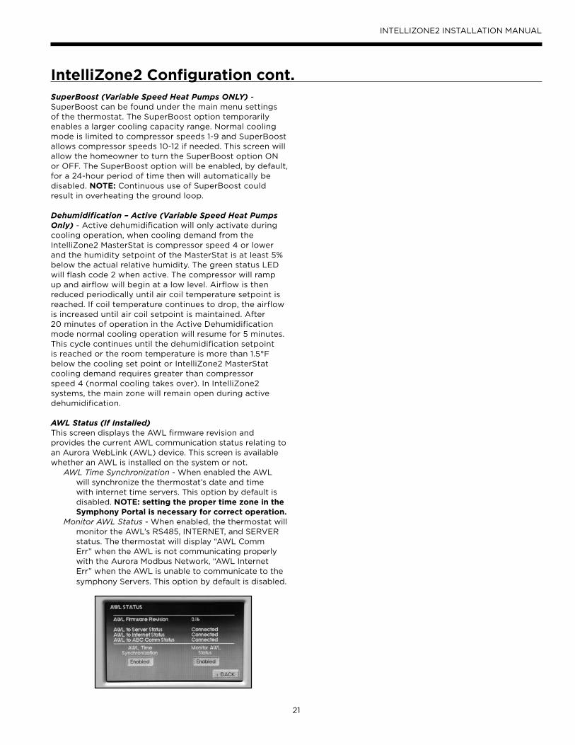
AWL Status (If Installed)This screen displays the AWL firmware revision and provides the current AWL communication status relating to an Aurora WebLink (AWL) device. This screen is available whether an AWL is installed on the system or not.
AWL Time Synchronization - When enabled the AWL will synchronize the thermostat’s date and time with internet time servers. This option by default is disabled. NOTE: setting the proper time zone in the Symphony Portal is necessary for correct operation.
Monitor AWL Status - When enabled, the thermostat will monitor the AWL’s RS485, INTERNET, and SERVER status. The thermostat will display “AWL Comm Err” when the AWL is not communicating properly with the Aurora Modbus Network, “AWL Internet Err” when the AWL is unable to communicate to the symphony Servers. This option by default is disabled.
22
INTELLIZONE2 INSTALLATION MANUAL
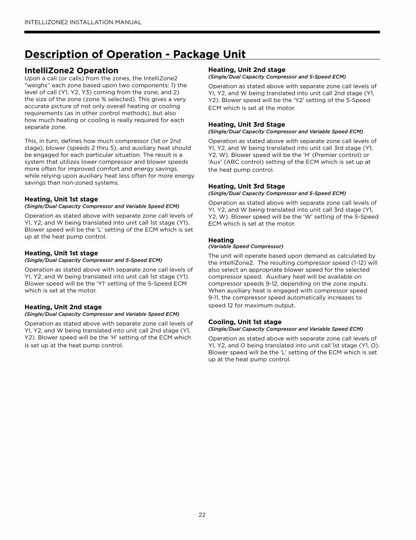
IntelliZone2 OperationUpon a call (or calls) from the zones, the IntelliZone2 “weighs” each zone based upon two components: 1) the level of call (Y1, Y2, Y3) coming from the zone; and 2) the size of the zone (zone % selected). This gives a very accurate picture of not only overall heating or cooling requirements (as in other control methods), but also how much heating or cooling is really required for each separate zone.
This, in turn, defines how much compressor (1st or 2nd stage), blower (speeds 2 thru 5), and auxiliary heat should be engaged for each particular situation. The result is a system that utilizes lower compressor and blower speeds more often for improved comfort and energy savings, while relying upon auxiliary heat less often for more energy savings than non-zoned systems.
Heating, Unit 1st stage (Single/Dual Capacity Compressor and Variable Speed ECM)
Operation as stated above with separate zone call levels of YI, Y2, and W being translated into unit call 1st stage (Y1). Blower speed will be the ‘L’ setting of the ECM which is set up at the heat pump control.
Heating, Unit 1st stage (Single/Dual Capacity Compressor and 5-Speed ECM)
Operation as stated above with separate zone call levels of YI, Y2, and W being translated into unit call 1st stage (Y1). Blower speed will be the ‘Y1’ setting of the 5-Speed ECM which is set at the motor.
Heating, Unit 2nd stage(Single/Dual Capacity Compressor and Variable Speed ECM)
Operation as stated above with separate zone call levels of YI, Y2, and W being translated into unit call 2nd stage (Y1, Y2). Blower speed will be the ‘H’ setting of the ECM which
is set up at the heat pump control.
Description of Operation - Package UnitHeating, Unit 2nd stage(Single/Dual Capacity Compressor and 5-Speed ECM)
Operation as stated above with separate zone call levels of YI, Y2, and W being translated into unit call 2nd stage (Y1, Y2). Blower speed will be the ‘Y2’ setting of the 5-Speed
ECM which is set at the motor.
Heating, Unit 3rd Stage(Single/Dual Capacity Compressor and Variable Speed ECM)
Operation as stated above with separate zone call levels of YI, Y2, and W being translated into unit call 3rd stage (Y1, Y2, W). Blower speed will be the ‘H’ (Premier control) or ‘Aux’ (ABC control) setting of the ECM which is set up at
the heat pump control.
Heating, Unit 3rd Stage(Single/Dual Capacity Compressor and 5-Speed ECM)
Operation as stated above with separate zone call levels of YI, Y2, and W being translated into unit call 3rd stage (Y1, Y2, W). Blower speed will be the ‘W’ setting of the 5-Speed ECM which is set at the motor.
Heating (Variable Speed Compressor)
The unit will operate based upon demand as calculated by the IntelliZone2. The resulting compressor speed (1-12) will also select an appropriate blower speed for the selected compressor speed. Auxiliary heat will be available on compressor speeds 9-12, depending on the zone inputs. When auxiliary heat is engaged with compressor speed 9-11, the compressor speed automatically increases to
speed 12 for maximum output.
Cooling, Unit 1st stage(Single/Dual Capacity Compressor and Variable Speed ECM)
Operation as stated above with separate zone call levels of YI, Y2, and O being translated into unit call 1st stage (Y1, O). Blower speed will be the ‘L’ setting of the ECM which is set up at the heat pump control.

23
INTELLIZONE2 INSTALLATION MANUAL
Description of Operation - Package Unit cont.Cooling, Unit 1st stage(Single/Dual Capacity Compressor and 5-Speed ECM)
Operation as stated above with separate zone call levels of YI, Y2, and O being translated into unit call 1st stage (Y1, O). Blower speed will be the ‘Y1’ setting of the 5-Speed ECM which is set at the motor.
Cooling, Unit 2nd stage(Single/Dual Capacity Compressor and Variable Speed ECM)
Operation as stated above with separate zone call levels of YI, Y2, and O being translated into unit call 2nd stage (Y1, Y2, O). Blower speed will be the ‘H’ setting of the ECM which is set up at the heat pump control.
Cooling, Unit 2nd stage(Single/Dual Capacity Compressor and 5-Speed ECM)
Operation as stated above with separate zone call levels of YI, Y2, and O being translated into unit call 2nd stage (Y1, Y2, O). Blower speed will be the ‘Y2’ setting of the 5-Speed ECM which is set at the motor.
Cooling(Variable Speed Compressor)
The unit will operate based upon demand as calculated by the IntelliZone2. The resulting compressor speed, speeds 1-9, (speeds 10-12 are reserved for SuperBoost mode only) will also select an appropriate blower speed.
Emergency HeatEmergency heat mode may be engaged by selecting at the MasterStat. All zone thermostat fault LED's begin to flash two quick flashes, followed by a pause, indicating that emergency heat mode has been activated. The temperature of the structure will be controlled by the zone 1 MasterStat while other zones are ignored. When a demand for heat occurs at the MasterStat all zone dampers are opened and emergency heat is energized. Emergency heat will continue to operate until the MasterStat demand is satisfied.
Emergency heat mode may be exited by selecting OFF (or one of the other mode selections) at the MasterStat, as well as all zone thermostat fault LED's stop flashing, indicating emergency heat mode has been deactivated and normal IntelliZone2 operation may resume.
Continuous BlowerThe unit's blower will be operated on blower speed 1 (G-LED) while heating or cooling is suspended for any zone(s) selected for continuous blower operation at the zone thermostat. Upon any heating or cooling call to the unit, all continuous blower operation ceases.
Lockout Mode(Single/Dual Speed Compressor)
During the unit lockout mode, the appropriate Fault code will be communicated to the IntelliZone2 MasterStat. The blower will continue to operate on blower speed 1. If the collective zones translate into a > 24% heating call, emergency heat operation will occur and all zone dampers
will open. Blower speed will be Aux Heat speed setting.
Lockout Mode(Variable Speed Compressor)
During lockout mode the appropriate Fault code will be communicated to the IntelliZone2 MasterStat. The blower will continue to operate on blower speed 'G'. If the collective zones translate into > 40%, all zone dampers will open and emergency heat operation will occur until the demand is < 24%.

24
INTELLIZONE2 INSTALLATION MANUAL
Blower Data - Package Unit
Airflow Selection (Single or Dual Capacity)When equipped with a Variable Speed ECM airflow from the Intellizone2 is communicated to the Aurora via a 'Blower Level %'. These blower levels are 55, 70, 85, and 100%. The Aurora will dictate actual airflow based upon these percentages. Below is a graphic showing how the IntelliZone2 would signal for a 55-100% blower level percent and the resulting airflow based upon the ABC setpoints of speed 5 for med and speed 8 for high in the example AID Tool setting. Notice that a blower level of 85% would result in a blower speed of 7 with these settings. All airflows are rounded to the nearest 1-12 blower speeds. Continuous blower and aux heat blower speeds are set Independently of the compressor blower speeds.
In cooling a similar procedure occurs with the exception that when dehumidification reduces airflow it is a reduction as shown below. Therefore in dehumidification mode, if blower speed 5 is selected the resulting airflow will be blower speed 5, less 15%. If cooling airflow is configured to be 15% less than heating airflow then there is no difference between cooling and dehumidification cooling airflow.
Heating Airflow Selection (Single or Dual Capacity)Selected in AID Tool
From IZ2Air Level %
Blower Speed
Cont Blower
Low HighAux Heat
1234
Comp Stage Low 55% 5 --->Comp Stage Low 70% 6Comp Stage High 85% 7Comp Stage High 100% 8 ---> --->
91011 --->12
NOTES:1) Continuous Blower activated by G only call from IntelliZone2
(selection can be anywhere)2) Aux Heat Airflow activated by Aux or Emergency heat call (selection
must be greater than high and allow proper airflow for the installed electric heat/heat pump model)-
Airflow Selection (Variable Speed)Airflow from the IntelliZone2 is communicated to the Aurora via a blower Level %. These blower levels are 25, 40, 55, 70, 85, and 100%. The Aurora will dictate actual airflow based upon these percentages. Below is a graphic showing how the IntelliZone2 would signal for a 25-100% blower level percent and the resulting airflow based upon the ABC setpoints of speed 3 for low and speed 8 for high in the example AID Tool setting. Notice that a Blower level of 85% would result in a blower speed of 7 with these settings. All airflows are rounded to the nearest 1-12 blower speeds. Continuous blower and aux heat blower speeds are set Independently of the compressor blower speeds.
Continued on the next page.
Cooling Airflow Selection (Single or Dual Capacity)Selected in AID Tool
From IZ2 Air Level %
Actual Blwr Spd*
Blwr Speed
Cont Blwr
Low HighAux Heat
1234
Comp Stage Low
55%Blwr Spd 5 - 15%
5 --->
Comp Stage Low
70%Blwr Spd 6 - 15%
6
Comp Stage High
85%Blwr Spd 7 - 15%
7
Comp Stage High
100%Blwr Spd 8 - 15%
8 ---> --->
91011 --->12
NOTES:1) Continuous Blower activated by G only call from IntelliZone2
(selection can be anywhere)2) Aux Heat Airflow activated by Aux or Emergency heat call (selection
must be greater than high and allow proper airflow for the installed electric heat/heat pump model)
Heating Airflow Selection (Variable Speed)Selected in AID Tool
From IZ2Air Level %
Blwr Speed
Cont Blwr
Low Comp
Hi Comp
Aux Heat
12
Comp Speeds 1 & 2
Low Selection
25% 3 --->
Comp Speeds 3 & 4
40% 4
Comp Speeds 5 & 6
55% 5
Comp Speeds 7 & 8
70% 6
Comp Speeds 9 & 10
85% 7
Comp Speeds 11 & 12
High Selection
100% 8 ---> --->
91011 --->12

25
INTELLIZONE2 INSTALLATION MANUAL
Blower Data - Package Unit cont.
Cooling Airflow Selection (Variable Speed)Selected in AID Tool
From IZ2 Air Level %
ActualBlower Speed*
AID Reported Blower Speed
Cont Blower Low Comp Hi Comp Aux Heat
12
Comp Speeds 1 & 2
Low Selection 25% Blower Spd 3 - 15% 3 --->
Comp Speeds 3 & 4
40% Blower Spd 4 - 15% 4
Comp Speeds 5 & 6
55% Blower Spd 5 - 15% 5
Comp Speeds 7 & 8
70% Blower Spd 6 - 15% 6
Comp Speeds 9 &10
Cooling Max 85% Blower Spd 7 - 15% 7
Comp Speeds 11 & 12
SuperBoost Only 100% Blower Spd 8 - 15% 8 ---> --->
91011 --->12
NOTE: * Denotes default cooling airflow setting of 15% less than heating mode airflow.
Dual or Single CapacityHeating Unit
CallBlower Level Call
(Norm)Blower Level Call
(Dehumid)
H1 55 or 70% na
H2 85 or 100% na
H2, W Aux Blower na
W Aux Blower na
G G Only (cont Blower) na
Cooling UnitCall
Blower Level Call(Norm)
Blower Level Call (Dehumid)
C1 55 or 70% 55 or 70% less 15% cfm
C2 85 or 100% 85 or 100% less 15% cfm
G G Only (cont Blower) G Only (cont Blower)
Variable Speed Capacity
Heating UnitCall
Blower Level Call (Normal Staging
Shown)
Blower Level Call (Dehumid)
H1 or H2 25% or 40% na
H3 or H4 25% or 40% or 55% na
H5 or H6 40% or 55% or 70% na
H7 or H8 55% or 70% or 85% na
H9 or H10 70% or 85% or 100% na
H11 or H12 85% or 100% na
H9-H12, W Aux Blower na
W Aux Blower na
G G Only (cont Blower) na
Cooling UnitCall
Blower Level Call (norm)
Blower Level Call (Dehumid)
C1 or C2 25% or 40% Norm less 15% cfm
C3 or C4 25% or 40% or 55% Norm less 15% cfm
C5 or C6 40% or 55% or 70% Norm less 15% cfm
C7 or C8 55% or 70% or 85% Norm less 15% cfm
C9 or C10 70% or 85% or 100% Norm less 15% cfm
C11 or C12 85% or 100% Norm less 15% cfm
G G Only (cont Blower) G Only (cont Blower)
NOTE: C10-C12 are only available in SuperBoost mode.
In cooling a similar procedure occurs with the exception that compressor speed is limited to a maximum of speed 9. However compressor speed 10-12 is available for a short period of time and the resulting airflow during the ‘SuperBoost’ mode is shown below. Another exception is when dehumidification reduces airflow; it is a reduction as shown below. Therefore, in dehumidification mode, if blower speed 3 is selected, the resulting airflow will be blower speed 3, less 15%.
26
INTELLIZONE2 INSTALLATION MANUAL
Blower Data - Package Unit cont.
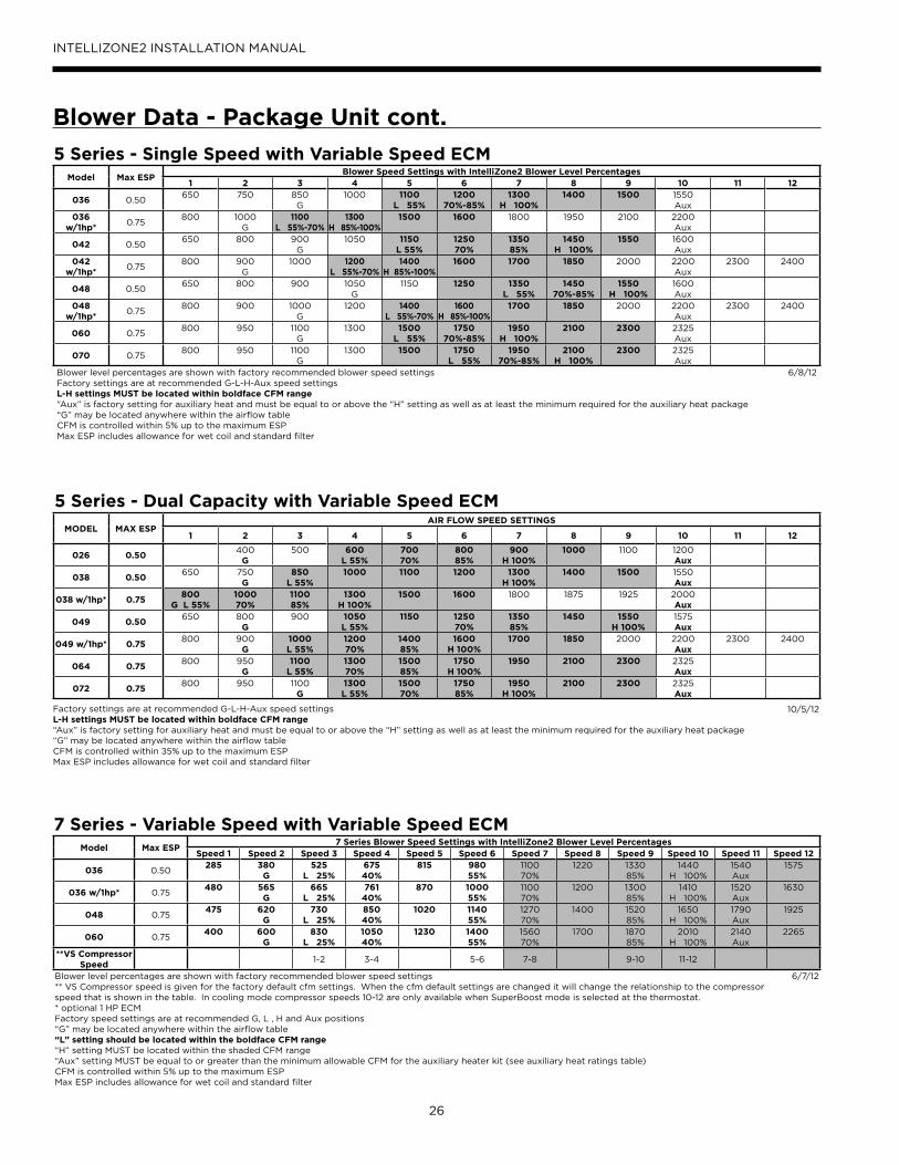
5 Series - Single Speed with Variable Speed ECMModel Max ESP
Blower Speed Settings with IntelliZone2 Blower Level Percentages1 2 3 4 5 6 7 8 9 10 11 12
036 0.50650 750 850
G1000 1100
L 55%1200
70%-85%1300
H 100%1400 1500 1550
Aux036
w/1hp*0.75
800 1000 G
1100 L 55%-70%
1300 H 85%-100%
1500 1600 1800 1950 2100 2200 Aux
042 0.50650 800 900
G1050 1150
L 55%1250 70%
1350 85%
1450 H 100%
1550 1600 Aux
042 w/1hp*
0.75800 900
G1000 1200
L 55%-70%1400
H 85%-100%1600 1700 1850 2000 2200
Aux2300 2400
048 0.50650 800 900 1050
G1150 1250 1350
L 55%1450
70%-85%1550
H 100%1600 Aux
048 w/1hp*
0.75800 900 1000
G1200 1400
L 55%-70%1600
H 85%-100%1700 1850 2000 2200
Aux2300 2400
060 0.75800 950 1100
G1300 1500
L 55%1750
70%-85%1950
H 100%2100 2300 2325
Aux
070 0.75800 950 1100
G1300 1500 1750
L 55%1950
70%-85%2100
H 100%2300 2325
AuxBlower level percentages are shown with factory recommended blower speed settingsFactory settings are at recommended G-L-H-Aux speed settingsL-H settings MUST be located within boldface CFM range“Aux” is factory setting for auxiliary heat and must be equal to or above the “H” setting as well as at least the minimum required for the auxiliary heat package“G” may be located anywhere within the airflow tableCFM is controlled within 5% up to the maximum ESPMax ESP includes allowance for wet coil and standard filter
6/8/12
7 Series - Variable Speed with Variable Speed ECMModel Max ESP
7 Series Blower Speed Settings with IntelliZone2 Blower Level PercentagesSpeed 1 Speed 2 Speed 3 Speed 4 Speed 5 Speed 6 Speed 7 Speed 8 Speed 9 Speed 10 Speed 11 Speed 12
036 0.50285 380
G525
L 25%675 40%
815 980 55%
1100 70%
1220 1330 85%
1440 H 100%
1540 Aux
1575
036 w/1hp* 0.75480 565
G665
L 25%761
40%870 1000
55%1100 70%
1200 1300 85%
1410H 100%
1520 Aux
1630
048 0.75475 620
G730
L 25%850 40%
1020 1140 55%
1270 70%
1400 1520 85%
1650 H 100%
1790 Aux
1925
060 0.75400 600
G830
L 25%1050 40%
1230 1400 55%
1560 70%
1700 1870 85%
2010 H 100%
2140 Aux
2265
**VS Compressor Speed
1-2 3-4 5-6 7-8 9-10 11-12
Blower level percentages are shown with factory recommended blower speed settings** VS Compressor speed is given for the factory default cfm settings. When the cfm default settings are changed it will change the relationship to the compressor speed that is shown in the table. In cooling mode compressor speeds 10-12 are only available when SuperBoost mode is selected at the thermostat.* optional 1 HP ECMFactory speed settings are at recommended G, L , H and Aux positions“G” may be located anywhere within the airflow table“L” setting should be located within the boldface CFM range“H” setting MUST be located within the shaded CFM range“Aux” setting MUST be equal to or greater than the minimum allowable CFM for the auxiliary heater kit (see auxiliary heat ratings table)CFM is controlled within 5% up to the maximum ESPMax ESP includes allowance for wet coil and standard filter
6/7/12
5 Series - Dual Capacity with Variable Speed ECM
MODEL MAX ESPAIR FLOW SPEED SETTINGS
1 2 3 4 5 6 7 8 9 10 11 12
026 0.50400
G500 600
L 55%70070%
80085%
900H 100%
1000 1100 1200Aux
038 0.50650 750
G850
L 55%1000 1100 1200 1300
H 100%1400 1500 1550
Aux
038 w/1hp* 0.75800
G L 55%100070%
110085%
1300H 100%
1500 1600 1800 1875 1925 2000Aux
049 0.50650 800
G900 1050
L 55%1150 1250
70%135085%
1450 1550H 100%
1575Aux
049 w/1hp* 0.75800 900
G1000L 55%
120070%
140085%
1600H 100%
1700 1850 2000 2200Aux
2300 2400
064 0.75800 950
G1100
L 55%130070%
150085%
1750H 100%
1950 2100 2300 2325Aux
072 0.75800 950 1100
G1300L 55%
150070%
175085%
1950H 100%
2100 2300 2325Aux
10/5/12Factory settings are at recommended G-L-H-Aux speed settingsL-H settings MUST be located within boldface CFM range“Aux” is factory setting for auxiliary heat and must be equal to or above the “H” setting as well as at least the minimum required for the auxiliary heat package“G” may be located anywhere within the airflow tableCFM is controlled within ±5% up to the maximum ESPMax ESP includes allowance for wet coil and standard filter

27
INTELLIZONE2 INSTALLATION MANUAL
Blower Data - Package Unit cont.
5 Series - Single Speed with 5-Speed ECM MotorModel
Motor Speed
Motor Tap
T’stat Cnct.
Blower Size
Motor HP
Airflow (cfm) at External Static Pressure (in. wg)0 0.05 0.10 0.15 0.20 0.25 0.30 0.35 0.40 0.45 0.50 0.60 0.70 0.80 0.90 1.00
022
High 5 W
9 x 7 1/2
980 960 940 930 920 905 890 875 860 840 820 800 745 - - -Med High 4 Y1 890 878 865 845 825 813 800 785 770 753 735 710 665 - - -
Med 3 830 815 800 788 775 755 735 723 710 690 670 640 600 - - -Med Low 2 G 780 760 740 703 665 653 640 620 600 585 570 - - - - -
Low 1 625 593 560 535 510 495 480 455 430 410 390 - - - - -
030
High 5
9 x 7 1/2
1407 1381 1354 1327 1300 1267 1233 1201 1168 1131 1094 1009 - - - -Med High 4 W 1146 1134 1122 1111 1099 1085 1071 1062 1052 1042 1031 966 - - - -
Med 3 Y1 1023 1012 1001 985 969 959 949 937 925 913 901 - - - - -Med Low 2 978 962 946 934 922 907 891 882 872 858 843 - - - - -
Low 1 G 795 777 759 748 737 718 698 686 673 650 626 - - - - -
036
High 5 W
11 x 10 1/2
1530 1503 1476 1453 1429 1413 1397 1376 1355 1342 1329 1276 1231 1173 - -Med High 4 Y1 1413 1388 1363 1342 1321 1303 1285 1263 1240 1226 1212 1173 1016 946 - -
Med 3 1355 1325 1294 1276 1258 1235 1212 1188 1164 1144 1123 982 909 883 - -Med Low 2 1336 1299 1261 1242 1222 1202 1181 1157 1132 1111 1090 937 874 830 - -
Low 1 G 1243 1182 1121 1061 1000 964 928 856 784 744 703 647 592 - -
042
High 5
11 x 10 1
1934 1910 1886 1871 1855 1827 1799 1780 1760 1747 1734 1700 1659 1617 - -Med High 4 W 1799 1783 1767 1744 1720 1693 1666 1649 1631 1617 1603 1560 1530 1492 - -
Med 3 1694 1680 1666 1642 1617 1592 1567 1552 1537 1519 1500 1453 1421 1372 - -Med Low 2 Y1 1575 1560 1540 1520 1502 1487 1471 1448 1424 1409 1393 1351 1308 1266 - -
Low 1 G 1454 1406 1358 1333 1308 1285 1261 1239 1217 1198 1179 1072 1002 988 - -
048
High 5
11 x 10 1
1934 1910 1886 1871 1855 1827 1799 1780 1760 1747 1734 1700 1659 1617 - -Med High 4 W 1799 1783 1767 1744 1720 1693 1666 1649 1631 1617 1603 1560 1530 1492 - -
Med 3 Y1 1694 1680 1666 1642 1617 1592 1567 1552 1537 1519 1500 1453 1421 1372 - -Med Low 2 1575 1560 1540 1520 1502 1487 1471 1448 1424 1409 1393 1351 1308 1266 - -
Low 1 G 1454 1406 1358 1333 1308 1285 1261 1239 1217 1198 1179 1072 1002 988 - -
060
High 5 W
11 x 10 1
2245 2230 2214 2194 2173 2155 2136 2120 2103 2087 2070 2032 1998 1957 1910 1825Med High 4 2092 2073 2054 2035 2015 1995 1975 1958 1940 1922 1904 1880 1843 1806 1767 1728
Med 3 1951 1931 1910 1889 1868 1850 1831 1812 1793 1774 1755 1722 1688 1654 1612 1562Med Low 2 Y1 1812 1796 1780 1761 1741 1718 1695 1682 1668 1651 1633 1591 1555 1518 1480 1433
Low 1 G 1682 1661 1640 1616 1591 1573 1555 1533 1510 1495 1480 1441 1400 1351 1316 1263
070
High 5 W
11 x 10 1
2472 2454 2435 2414 2393 2371 2349 2328 2306 2289 2271 2230 2189 2121 2033 1936Med High 4 Y1 2271 2248 2225 2205 2184 2166 2147 2129 2110 2094 2078 2039 2011 1977 1930 1846
Med 3 2133 2115 2096 2072 2047 2030 2013 1996 1979 1965 1950 1909 1873 1837 1793 1748Med Low 2 2008 1985 1962 1939 1915 1898 1880 1862 1843 1828 1812 1774 1742 1703 1669 1635
Low 1 G 1806 1784 1761 1742 1722 1696 1669 1656 1642 1625 1607 1564 1527 1490 1443 1404Factory speed settings are in BoldAir flow values are with dry coil and standard filterFor wet coil performance first calculate the face velocity of the air coil (Face Velocity [fpm] = Airflow [cfm] / Face Area [sq ft]). Then for velocities of 200 fpm reduce the static capability by 0.03 in. wg, 300 fpm by 0.08 in. wg, 400 fpm by 0.12in. wg., and 500 fpm by 0.16 in. wg.Highest setting is for auxiliary heat (W) and lowest setting is for constant blower (G). The “Y1” and “Y2” settings must be between the “G” and “W” settings.The gray wire is not factory wired to the motor and is tied to the wire harness. This wire can be field connected and can be used with 3ht/2cl thermostats or IntelliZone2 to deliver the required air flow for the Y2 signal.
6/14/12
5 Series - Dual Capacity with 5-Speed ECMModel
Motor Speed
Motor Tap
T’stat Cnct.
Blower Size
Motor HP
Airflow (cfm) at External Static Pressure (in. wg)0 0.05 0.10 0.15 0.20 0.25 0.30 0.35 0.40 0.45 0.50 0.60 0.70 0.80 0.90 1.00
026
High 5 W
9 x 7 1/2
1120 1109 1097 1082 1066 1055 1044 1028 1011 1001 991 932 839 - - -Med High 4 Y2 1020 1006 991 980 968 950 932 922 911 894 876 849 812 - - -
Med 3 917 906 895 884 872 854 836 824 812 792 772 754 719 - - -Med Low 2 Y1 836 824 812 794 776 765 754 735 715 703 691 653 631 - - -
Low 1 G 735 721 707 687 666 653 640 622 603 589 574 533 - - - -
038
High 5 W
11 x 10 1/2
1530 1503 1476 1453 1429 1413 1397 1376 1355 1342 1329 1276 1231 1173 - -Med High 4 Y2 1413 1388 1363 1342 1321 1303 1285 1263 1240 1226 1212 1173 1016 946 - -
Med 3 Y1 1355 1325 1294 1276 1258 1235 1212 1188 1164 1144 1123 982 909 883 - -Med Low 2 1336 1299 1261 1242 1222 1202 1181 1157 1132 1111 1090 937 874 830 - -
Low 1 G 1243 1182 1121 1061 1000 964 928 856 784 744 703 647 592 - -
049
High 5 W
11 x 10 1
1934 1910 1886 1871 1855 1827 1799 1780 1760 1747 1734 1700 1659 1617 - -Med High 4 1799 1783 1767 1744 1720 1693 1666 1649 1631 1617 1603 1560 1530 1492 - -
Med 3 Y2 1694 1680 1666 1642 1617 1592 1567 1552 1537 1519 1500 1453 1421 1372 - -Med Low 2 Y1 1575 1560 1540 1520 1502 1487 1471 1448 1424 1409 1393 1351 1308 1266 - -
Low 1 G 1454 1406 1358 1333 1308 1285 1261 1239 1217 1198 1179 1072 1002 988 - -
064
High 5 W
11 x 10 1
2245 2230 2214 2194 2173 2155 2136 2120 2103 2087 2070 2032 1998 1957 1910 1825Med High 4 Y2 2092 2073 2054 2035 2015 1995 1975 1958 1940 1922 1904 1880 1843 1806 1767 1728
Med 3 1951 1931 1910 1889 1868 1850 1831 1812 1793 1774 1755 1722 1688 1654 1612 1562Med Low 2 Y1 1812 1796 1780 1761 1741 1718 1695 1682 1668 1651 1633 1591 1555 1518 1480 1433
Low 1 G 1682 1661 1640 1616 1591 1573 1555 1533 1510 1495 1480 1441 1400 1351 1316 1263
072
High 5 W
11 x 10 1
2472 2454 2435 2414 2393 2371 2349 2328 2306 2289 2271 2230 2189 2121 2033 1936Med High 4 Y2 2271 2248 2225 2205 2184 2166 2147 2129 2110 2094 2078 2039 2011 1977 1930 1846
Med 3 2133 2115 2096 2072 2047 2030 2013 1996 1979 1965 1950 1909 1873 1837 1793 1748Med Low 2 Y1 2008 1985 1962 1939 1915 1898 1880 1862 1843 1828 1812 1774 1742 1703 1669 1635
Low 1 G 1806 1784 1761 1742 1722 1696 1669 1656 1642 1625 1607 1564 1527 1490 1443 1404Factory speed settings are in BoldAir flow values are with dry coil and standard filterFor wet coil performance first calculate the face velocity of the air coil (Face Velocity [fpm] = Airflow [cfm] / Face Area [sq ft]). Then for velocities of 200 fpm reduce the static capability by 0.03 in. wg, 300 fpm by 0.08 in. wg, 400 fpm by 0.12in. wg., and 500 fpm by 0.16 in. wg.Highest setting is for auxiliary heat (W) and lowest setting is for constant blower (G). The “Y1” and “Y2” settings must be between the “G” and “W” settings.
6/14/12

28
INTELLIZONE2 INSTALLATION MANUAL
It should be noted that the MasterStat Z2TK
troubleshooting harness can be useful during startup
by allowing the temporary connection of the MasterStat
directly at the IntelliZone2 relay board for ease of
configuration or servicing.
Before powering the unit, check the following:
• Fuses, breakers and wire size are correct.
• Low voltage wiring has been completed.
• MasterStat has been configured correctly.
• Thermostats are wired and DIP switches are set for
proper zone #.
• Blower speed has been set on the AID Tool.
• Aurora control is configured for IntelliZone2.
System Startup and Checkout
Damper Open -CCW
Damper Closed -CW
Shaft End Position Indicator
ManualReleaseButton
Rotate by hand
Figure 25: Checking the Shaft Position Indicator
ModelMaxCFM
Zone Design CFM
CFMPercentage
NS030 1000 700 50
NS036 1200 850 50
NS042 1300 900 50
NS048 1500 1000 50
NS060 1800 1100 50
NS070 2000 1100 50
ND026 800 600 40
ND038 1200 600 40
ND049 1500 800 40
ND064 1800 950 40
ND072 2000 1100 40
NV036 1500 300 20
NV048 1800 450 20
NV060 2100 450 20
IntelliZone2 CFM Design
Damper and Continuous Blower Checkout1. Push the “Fan” button to the ON position on all
thermostats. (alternate method shown in the
note below)
2. All dampers should start to open immediately.
3. The blower should come on continuous fan speed. The
green zone LED’s flash while the dampers are opening,
once completely open the green LED will be solid ON.
The amber LED will illuminate to indicate fan ON.
4. After approximately 100 seconds, all IntelliZone2
dampers should be completely opened. Check the
shaft position indicator on all damper actuators as
shown in Figure 25.
5. Push the “Fan” button to the OFF position on
all thermostats.
6. The blower and the amber LED should cycle off.
7. All dampers should start to close immediately. After
approximately 100 seconds, all dampers should be
completely closed. Check the shaft position indicator
on all damper actuators shown in Figure 25.
NOTES: To cycle dampers open and closed, access the
‘Test Mode’ Screen in the Installer Setup mode on the
IntelliZone2 MasterStat. Once here each damper can be
cycled individually by pushing the specific zone damper
button to check for proper operation. “Central Zone” mode
can also be used to open all dampers.
(3-wire PO/PC actuator shown)

29
INTELLIZONE2 INSTALLATION MANUAL
In the following procedure, check for proper calls on the
Status Screen.
System Checkout1. Set all of the zone thermostats to the cooling mode.
2. Reduce the cooling set point to 1° below the actual
zone temperature on all thermostats.
3. First stage cooling should energize after a delay.
4. Be sure the compressor and blower are activated.
Check that the zone, cool, and fan speed LEDs are on.
5. Decrease the cooling set point two more degrees and
check to see that the fan speed increases and second
stage cooling is energized. Using the AID tool, check the
fan speed and compare to the Blower Speed tables.
6. In variable speed applications, when operating in low
compressor speeds, ensure that there is adequate air
flow from each register so as to get sufficient throw into
the conditioned space. If there is not sufficient airflow, try
increasing the selected blower speed.
7. Adjust the thermostats until the temperature displayed is
5° higher than the actual temperature on all thermostats.
8. The call for cooling should be canceled after a delay.
9. Set all of the zone thermostats to the heating mode.
10. Increase the heating set point to 1° above the actual
zone temperature on all thermostats.
11. After a delay, the unit should start up in the first stage
heating mode (H1). Using the AID tool, check the fan
speed and compare to the Blower Speed tables.
12. Increase the heating set points two more degrees and
check to see that the fan speed increases and second
stage heating is energized (H2). Using the AID tool
check the fan speed and compare to the Blower Speed
table.
13. Increase the heating set point to 4° above the actual
zone temperatures. Be sure the auxiliary heat is
energized and the fan speed increases. Using the AID
tool check the fan speed and compare to the Blower
Speed tables.
14. Set system to maintain desired comfort level.
15. Instruct the owner/operator of correct thermostat and
system operation.
16. Fill out and forward all warranty registration papers
to WaterFurnace.
System Startup and Checkout cont.NOTE: Unit check out can be accomplished by going to the
Test Mode screen at the MasterStat and selecting Central
Zone. The system will be controlled only by the MasterStat.
Any time superheat and subcooling is being checked, the
zone system must be in the central zone mode.
Blower Speed TablesSingle or Dual Capacity
Heating Unit Call
Blower Level Call(Norm)
Blower Level Call (Dehumid)
H1 55 or 70% N/A
H2 85 or 100% N/A
H2, W Aux Blower N/A
W Aux Blower N/A
G G Only (Cont Blower) N/A
Cooling Unit Call
Blower Level Call(Norm)
Blower Level Call (Dehumid)
C1 55 or 70% 55 or 70% less 15% cfm
C2 85 or 100% 85 or 100% less 15% cfm
G G Only (Cont Blower) G Only (Cont Blower)
Variable Speed CapacityHeating Unit Call
Blower Level Call(Normal Staging Shown)
Blower Level Call(Dehumid)
H1 or H2 25% N/A
H3 or H4 40% N/A
H5 or H6 55% N/A
H7 or H8 70% N/A
H9 or H10 85% N/A
H11 or H12 100% N/A
H9-H12, W Aux Blower N/A
W Aux Blower N/A
G G Only (Cont Blower) N/A
Cooling Unit Call
Blower Level Call(Norm)
Blower Level Call (Dehumid)
C1 or C2 25% 25% less 15% cfm
C3 or C4 40% 40% less 15% cfm
C5 or C6 55% 55% less 15% cfm
C7 or C8 70% 70% less 15% cfm
C9 or C10 85% 85% less 15% cfm
C11 or C12 100% 100% less 15% cfm
G G Only (Cont Blower) G Only (Cont Blower)
IntelliZone2 ConfigurationOnce added to the Aurora control system, the setup and
configuration mode should be entered at the MasterStat by
holding a finger on the IntelliZone2 logo for 5 seconds. The
Configuration and Setup mode will appear automatically.
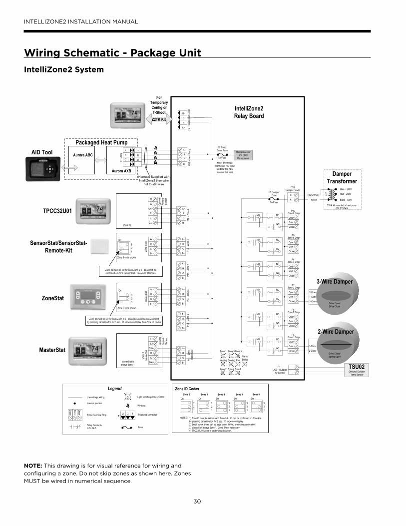
30
INTELLIZONE2 INSTALLATION MANUAL
Wiring Schematic - Package Unit
IntelliZone2 System
75VA kit mounted in heat pump (PN ZTK240)
A+
R
C
B-
P11 –
Zon
e 1Ma
sterS
tat
A+
R
C
B-
P12 –
Zon
e 2
A+
R
C
B-
P13 –
Zon
e 3
A+
R
C
B-
P14 –
Zon
e 4
A+
R
C
B-
P15 –
Zon
e 5
A+
R
C
B-
P16 –
Zon
e 6
A+
R
C
B-
P3 –
Maste
rStat
Loca
l
C
B-
A+
R
P17 –
Hea
t Pum
p
NO NO
NCCom
Close
Zone 1 Dmpr
Open
P5
NO NO
NCCom
Close
Zone 2 Dmpr
Open
P6
NO NO
NCCom
Close
Zone 3 Dmpr
Open
P7
NO NO
NCCom
Close
Zone 4 Dmpr
Open
P8
NO NO
NCCom
Close
Zone 5 Dmpr
Open
P9
NO NO
NCCom
Close
Zone 6 Dmpr
Open
P10
LAS – Outdoor Air Sensor
P1
G G G
RR B Y
G G G
Zone 1
Zone 2
Heating Cooling
Zone 3
Zone 4 Zone 6
Zone 5
FanAlarm/Status
R
C
P18Damper Power
F1 DamperFuse
F2 Relay Board Fuse
IntelliZone2 Relay Board
DX+
R
C
DX-
Zone
1Ma
sterS
tatMasterStat
A+
R
C
B-
Zone
3 St
atOn32 1
Zone 3 code shown
A+
R
C
B-
Zone
5 St
atOn32 1
Zone 5 code shown
ZoneStat
SensorStat/SensorStat- Remote-Kit
MasterStat is always Zone 1
+
R
C
-
P7 -
Zone
Aurora AXB
Aurora ABC
Packaged Heat Pump
For Temporary Config or T-ShootZ2TK Kit
Damper Transformer
24V
Blue – 240V
Black - Com
Red – 208V
2-Wire Damper
1-Com
3-Close
2-Open
Drive Close/Spring Open
Drive Open/Drive Close
3-Wire Damper
Zone ID must be set for each Zone 2-6. ID can be confirmed on ZoneStat by pressing cancel button for 5 sec. ID shown on display. See Zone ID Codes.
Zone ID must be set for each Zone 2-6. ID cannot be confirmed on Zone Sensor Stat. See Zone ID Codes.
AID Tool
TSU02Optional Outdoor
Temp Sensor
Black/White
Yellow5A Fuse
3A Fuse
Light emitting diode - Green
Polarized connector
Low voltage wiring
Internal junction
Fuse
Legend
Relay Contacts-N.O., N.C.
G
132PScrew Terminal Strip
Com
Close
Open
On32 1
On32 1
On32 1
Zone 4 Zone 5Zone 3On
32 1
Zone 2On
32 1
Zone 6
Zone ID Codes
1) Zone ID must be set for each Zone 2-6. ID can be confirmed on ZoneStat by pressing cancel button for 5 sec. ID shown on display.2) Small screw driver can be used to set ID thru protective plastic skin!3) MasterStat always Zone 1. Zone ID not necessary4) TPCC32U01 zone is set thru touchscreen.
NOTES:
R
+
-
C
Harness Supplied withIntelliZone2 then wire
nut to stat wire
Wire nut
1-Com
2-Close
S1
S2 Optio
nal
Remo
te Se
nsor
Microprocessor and other
Components
TPCC32U01 DX+
R
C
DX-(Note 4)
S1
S2 Optio
nal
Remo
te Se
nsor
Note: Shorting a thermostat R/C input
will blow the ABC fuse not this fuse
NOTE: This drawing is for visual reference for wiring and
configuring a zone. Do not skip zones as shown here. Zones
MUST be wired in numerical sequence.
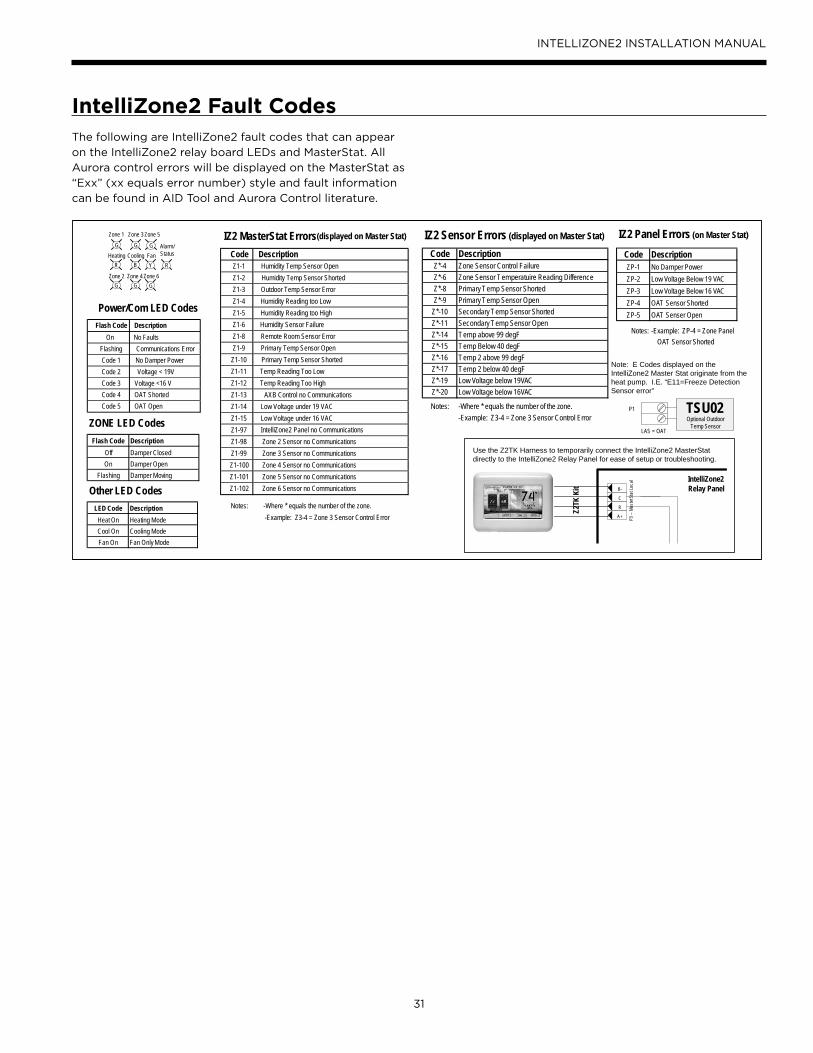
31
INTELLIZONE2 INSTALLATION MANUAL
IntelliZone2 Fault CodesThe following are IntelliZone2 fault codes that can appear
on the IntelliZone2 relay board LEDs and MasterStat. All
Aurora control errors will be displayed on the MasterStat as
“Exx” (xx equals error number) style and fault information
can be found in AID Tool and Aurora Control literature.
P3 –
Mast
erSt
at Lo
cal
C
B-
A+
RZ2TK
Kit
IntelliZone2 Relay Panel
G G G
RR B Y
G G G
Zone 1
Zone 2
Heating Cooling
Zone 3
Zone 4 Zone 6
Zone 5
FanAlarm/Status
ZONE LED CodesFlash Code Description
Off Damper ClosedOn Damper Open
Flashing Damper Moving
Other LED CodesLED Code Description
Heat On Heating ModeCool On Cooling ModeFan On Fan Only Mode
IZ2 Sensor Errors (displayed on Master Stat)
Code DescriptionZ*-4 Zone Sensor Control FailureZ*-6 Zone Sensor Temperatuire Reading DifferenceZ*-8 Primary Temp Sensor ShortedZ*-9 Primary Temp Sensor Open
Z*-10 Secondary Temp Sensor ShortedZ*-11 Secondary Temp Sensor OpenZ*-14 Temp above 99 degFZ*-15 Temp Below 40 degFZ*-16 Temp 2 above 99 degFZ*-17 Temp 2 below 40 degFZ*-19 Low Voltage below 19VACZ*-20 Low Voltage below 16VAC
Notes: -Where * equals the number of the zone.-Example: Z3-4 = Zone 3 Sensor Control Error
(displayed on Master Stat)
Notes: -Where * equals the number of the zone.-Example: Z3-4 = Zone 3 Sensor Control Error
Note: E Codes displayed on theIntelliZone2 Master Stat originate from theheat pump. I.E. “E11=Freeze DetectionSensor error”
IZ2 Panel Errors (on Master Stat)
Code DescriptionZP-1 No Damper PowerZP-2 Low Voltage Below 19 VACZP-3 Low Voltage Below 16 VACZP-4 OAT Sensor ShortedZP-5 OAT Senser Open
Notes: -Example: ZP-4 = Zone Panel OAT Sensor Shorted
Power/Com LED CodesFlash Code Description
On No FaultsFlashing Communications ErrorCode 1 No Damper PowerCode 2 Voltage < 19VCode 3 Voltage <16 VCode 4 OAT ShortedCode 5 OAT Open
IZ2 MasterStat ErrorsCode DescriptionZ1-1 Humidity Temp Sensor OpenZ1-2 Humidity Temp Sensor ShortedZ1-3 Outdoor Temp Sensor ErrorZ1-4 Humidity Reading too LowZ1-5 Humidity Reading too HighZ1-6 Humidity Sensor FailureZ1-8 Remote Room Sensor ErrorZ1-9 Primary Temp Sensor Open
Z1-10 Primary Temp Sensor ShortedZ1-11 Temp Reading Too LowZ1-12 Temp Reading Too HighZ1-13 AXB Control no CommunicationsZ1-14 Low Voltage under 19 VACZ1-15 Low Voltage under 16 VACZ1-97 IntelliZone2 Panel no CommunicationsZ1-98 Zone 2 Sensor no CommunicationsZ1-99 Zone 3 Sensor no CommunicationsZ1-100 Zone 4 Sensor no CommunicationsZ1-101 Zone 5 Sensor no CommunicationsZ1-102 Zone 6 Sensor no Communications
Use the Z2TK Harness to temporarily connect the IntelliZone2 MasterStatdirectly to the IntelliZone2 Relay Panel for ease of setup or troubleshooting.
P1 TSU02Optional Outdoor
Temp SensorLAS = OAT


33
INTELLIZONE2 INSTALLATION MANUAL
IntelliZone2 with SAH Air Handler

34
INTELLIZONE2 INSTALLATION MANUAL
Transformer MountingIt is not recommended to mount the zone transformer in the 5 Series Outdoor Split compressor section and should be
mounted to the air handler. For the 5 Series Indoor Split the zone transformer can be mounted to the air handler or in the
compressor section. If the zone transformer is mounted to the air handler power will come from the PB located in the Air
Handler electrical compartment. Depending on the air handler configuration, connect the zone transformer primary leads
to the quick connect or screw lug terminals. All wiring connections have to be made inside the electrical box area. Wrap the
third (unused) primary lead with electrical tape and secure.
Electrical Wiring
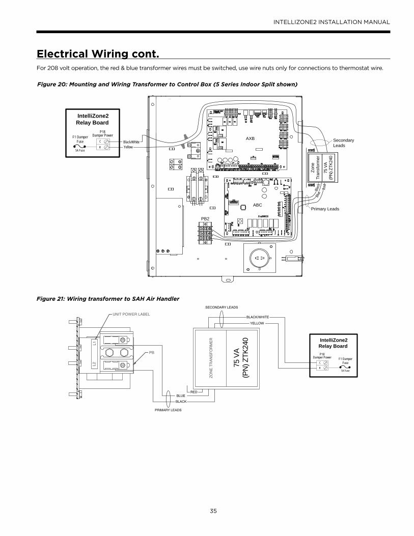
35
INTELLIZONE2 INSTALLATION MANUAL
For 208 volt operation, the red & blue transformer wires must be switched, use wire nuts only for connections to thermostat wire.
Figure 20: Mounting and Wiring Transformer to Control Box (5 Series Indoor Split shown)
Figure 21: Wiring transformer to SAH Air Handler
R
C
P18Damper PowerF1 Damper
Fuse Black/White
5A Fuse
IntelliZone2Relay Board
Primary Leads
SecondaryLeads
Zone
Tran
sfor
mer
75 V
A(P
N) Z
TK24
0
Black
Blue
Red
Yellow
AXB
ABC
PB2
UNIT POWER LABEL
L1L2
PB
ZONE
TRA
NSFO
RMER
R
C
P18Damper Power F1 Damper
Fuse
5A Fuse
IntelliZone2Relay Board
BLUERED
PRIMARY LEADS
BLACK
SECONDARY LEADS
BLACK/WHITE
YELLOW
75 V
A(P
N) Z
TK24
0
Electrical Wiring cont.
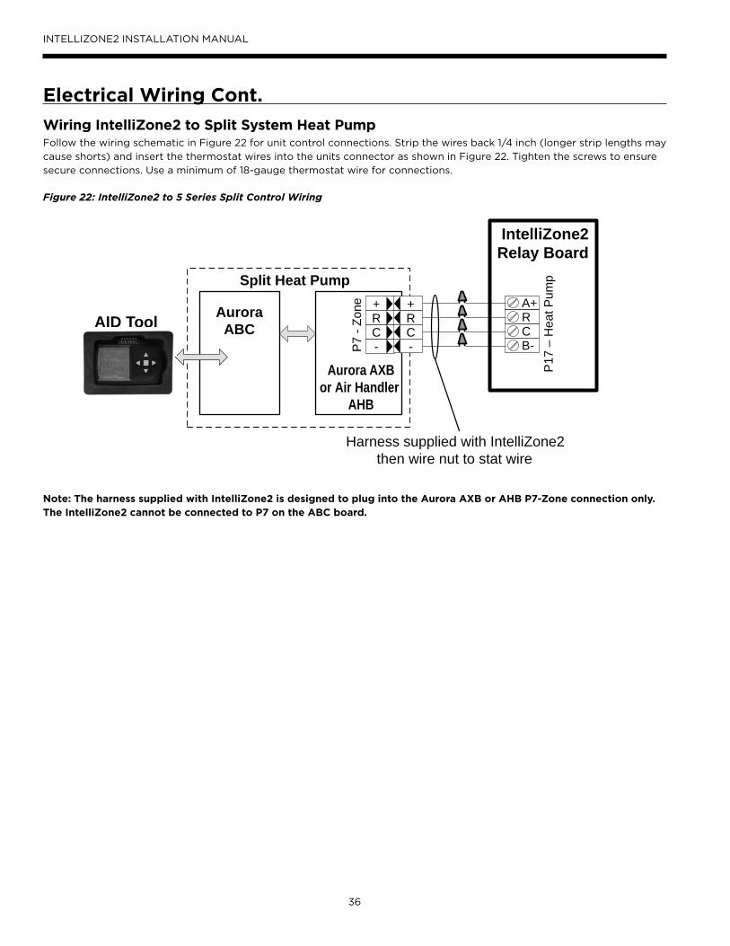
36
INTELLIZONE2 INSTALLATION MANUAL
Wiring IntelliZone2 to Split System Heat PumpFollow the wiring schematic in Figure 22 for unit control connections. Strip the wires back 1/4 inch (longer strip lengths may
cause shorts) and insert the thermostat wires into the units connector as shown in Figure 22. Tighten the screws to ensure
secure connections. Use a minimum of 18-gauge thermostat wire for connections.
Electrical Wiring Cont.
Figure 22: IntelliZone2 to 5 Series Split Control Wiring
A+RCB-
P17
– H
eat P
ump
+RC-P
7 - Z
one
Aurora AXBor Air Handler
AHB
AuroraABC
Split Heat Pump
R+
-C
Harness supplied with IntelliZone2then wire nut to stat wire
AID Tool
IntelliZone2Relay Board
Note: The harness supplied with IntelliZone2 is designed to plug into the Aurora AXB or AHB P7-Zone connection only. The IntelliZone2 cannot be connected to P7 on the ABC board.

37
INTELLIZONE2 INSTALLATION MANUAL
IntelliZone2 Split OperationFor the split system to be compatible with IntelliZone2 there must be either an AXB in the compressor section or an AHB in the SAH Air Handler. As always an ABC board must be in the comressor section as well.
Upon a call (or calls) from the zones, the IntelliZone2 “weighs” each zone based upon two components: 1) the level of call (Y1, Y2, Y3) coming from the zone; and 2) the size of the zone (zone % selected). This gives a very accurate picture of not only overall heating or cooling requirements (as in other control methods), but also how much heating or cooling is really required for each separate zone.
This, in turn, defines how much compressor (1st or 2nd stage), blower and auxiliary heat should be engaged for each particular situation. The result is a system that utilizes lower compressor speed more often for improved comfort and energy savings, while relying upon auxiliary heat less often for more energy savings than non-zoned systems.
The variable speed ECM motor allows 6 air flow levels with IntelliZone2 while the 5 Speed ECM will allow 4 air flow levels. Althought the 5 speed ECM works with the IntelliZone2 the additional available air flow levels and air flow adjustability make the variable speed ECM the better option for zoning.
Heating, Unit 1st stage (Single/Dual Capacity Compressor and Variable Speed ECM)
Operation as stated above with separate zone call levels of YI, Y2, and W being translated into unit call 1st stage (Y1). Blower speed will be the ‘L’ setting of the ECM which is set up at the heat pump control.
Heating, Unit 1st stage (Single/Dual Capacity Compressor and 5-Speed ECM)
Operation as stated above with separate zone call levels of YI, Y2, and W being translated into unit call 1st stage (Y1). Blower speed will be the ‘Y1’ setting of the 5-Speed ECM which is set at the motor.
Heating, Unit 2nd stage(Single/Dual Capacity Compressor and Variable Speed ECM)
Operation as stated above with separate zone call levels of YI, Y2, and W being translated into unit call 2nd stage (Y1, Y2). Blower speed will be the ‘H’ setting of the ECM which
is set up at the heat pump control.
Heating, Unit 2nd stage(Single/Dual Capacity Compressor and 5-Speed ECM)
Operation as stated above with separate zone call levels of YI, Y2, and W being translated into unit call 2nd stage (Y1, Y2). Blower speed will be the ‘Y2’ setting of the 5-Speed
ECM which is set at the motor.
Heating, Unit 3rd Stage(Single/Dual Capacity Compressor and Variable Speed ECM)
Operation as stated above with separate zone call levels of YI, Y2, and W being translated into unit call 3rd stage (Y1, Y2, W). Blower speed will be the ‘H’ (Premier control) or ‘Aux’ (ABC control) setting of the ECM which is set up at
the heat pump control.
Heating, Unit 3rd Stage(Single/Dual Capacity Compressor and 5-Speed ECM)
Operation as stated above with separate zone call levels of YI, Y2, and W being translated into unit call 3rd stage (Y1, Y2, W). Blower speed will be the ‘W’ setting of the 5-Speed
ECM which is set at the motor.
Cooling, Unit 1st stage(Single/Dual Capacity Compressor and Variable Speed ECM)
Operation as stated above with separate zone call levels of YI, Y2, and O being translated into unit call 1st stage (Y1, O). Blower speed will be the ‘L’ setting of the ECM which is set up at the heat pump control.
Cooling, Unit 1st stage(Single/Dual Capacity Compressor and 5-Speed ECM)
Operation as stated above with separate zone call levels of YI, Y2, and O being translated into unit call 1st stage (Y1, O). Blower speed will be the ‘Y1’ setting of the 5-Speed ECM which is set at the motor.
Cooling, Unit 2nd stage(Single/Dual Capacity Compressor and Variable Speed ECM)
Operation as stated above with separate zone call levels of YI, Y2, and O being translated into unit call 2nd stage (Y1, Y2, O). Blower speed will be the ‘H’ setting of the ECM which is set up at the heat pump control.
Cooling, Unit 2nd stage(Single/Dual Capacity Compressor and 5-Speed ECM)
Operation as stated above with separate zone call levels of YI, Y2, and O being translated into unit call 2nd stage (Y1, Y2, O). Blower speed will be the ‘Y2’ setting of the 5-Speed ECM which is set at the motor.
Dehumidification (Variable Speed ECM)If dehumidification is desired it is set via the AID Tool on the ABC control by selecting -5% to -15% in the cooling airflow setup or by setting SW2-4 to OFF on the Premier control (85% of normal CFM). Not available with 5-Speed ECM
Description of Operation - Split System
38
INTELLIZONE2 INSTALLATION MANUAL
Description of Operation - Split System cont.Emergency HeatEmergency heat mode may be engaged by selecting at the MasterStat. All zone thermostat fault LED's begin to flash two quick flashes, followed by a pause, indicating that emergency heat mode has been activated. The temperature of the structure will be controlled by the zone 1 MasterStat while other zones are ignored. When a demand for heat occurs at the MasterStat all zone dampers are opened and emergency heat is energized. Emergency heat will continue to operate until the MasterStat demand is satisfied.
Emergency heat mode may be exited by selecting OFF (or one of the other mode selections) at the MasterStat, as well as all zone thermostat fault LED's stop flashing, indicating emergency heat mode has been deactivated and normal IntelliZone2 operation may resume.
Continuous BlowerAll dampers are open and the unit's blower will be operated while heating or cooling is suspended for any zone(s) selected for continuous blower operation at the zone thermostat. Upon any heating or cooling call to the unit, all continuous blower operation ceases.
Lockout Mode(Single/Dual Speed Compressor)
During the unit lockout mode, the appropriate Fault code will be communicated to the MasterStat and the blower will operate continuously. If the collective zones translate into a > 24% heating call, emergency heat operation will
occur and all zone dampers will open. Blower speed will be
highest selected speed setting at the heat pump.

39
INTELLIZONE2 INSTALLATION MANUAL
SAH 5 Speed ECM Blower Performance Data Option A
ModelMotor Speed
Motor Tap
T’stat Connection
Blower Size
Motor HP
Airflow (cfm) at External Static Pressure (in. wg)
0 0.05 0.10 0.15 0.20 0.25 0.30 0.35 0.40 0.45 0.50 0.60 0.70 0.80 0.90 1.00
022
High 5 W
9 x 7 1/2
1130 1115 1100 1090 1080 1065 1050 1040 1030 1015 1000 980 950 - - -
Med High 4 Y2* 1040 1025 1010 1000 990 975 960 945 930 915 900 880 850 - - -
Med 3 950 935 920 905 890 875 860 845 830 815 800 760 730 - - -
Med Low 2 Y1 860 845 830 815 800 785 770 755 740 720 700 660 590 - - -
Low 1 G 740 720 700 680 660 645 630 605 580 540 500 460 - - - -
026
High 5 W
9 x 7 1/2
1130 1115 1100 1090 1080 1065 1050 1040 1030 1015 1000 980 950 - - -
Med High 4 Y2* 1040 1025 1010 1000 990 975 960 945 930 915 900 880 850 - - -
Med 3 950 935 920 905 890 875 860 845 830 815 800 760 730 - - -
Med Low 2 Y1 860 845 830 815 800 785 770 755 740 720 700 660 590 - - -
Low 1 G 740 720 700 680 660 645 630 605 580 540 500 460 - - - -
030
High 5 W
9 x 7 1/2
1220 1205 1190 1180 1170 1160 1150 1140 1130 1115 1100 1050 930 - - -
Med High 4 Y2* 1130 1115 1100 1090 1080 1070 1060 1045 1030 1015 1000 980 950 - - -
Med 3 1040 1030 1020 1005 990 975 960 945 930 915 900 890 850 - - -
Med Low 2 Y1 950 935 920 905 890 875 860 845 830 815 800 770 730 - - -
Low 1 G 790 770 750 735 720 700 680 660 640 620 600 530 500 - - -
036
High 5 W
10 x 8 1/2
1450 1435 1420 1405 1390 1375 1360 1345 1330 1315 1300 1270 1250 1210 - -
Med High 4 Y2* 1350 1335 1320 1305 1290 1275 1260 1245 1230 1215 1200 1170 1140 1100 - -
Med 3 Y1 1170 1150 1130 1115 1100 1080 1060 1045 1030 1015 1000 960 920 880 - -
Med Low 2 1000 980 960 940 920 905 890 870 850 825 800 760 710 650 - -
Low 1 G 990 915 840 800 760 730 700 680 660 630 600 520 470 430 - -
042
High 5 W
11 x 10 1
1960 1945 1930 1915 1900 1880 1860 1845 1830 1810 1790 1750 1700 1660 - -
Med High 4 Y2* 1790 1775 1760 1745 1730 1710 1690 1670 1650 1535 1420 1560 1500 1450 - -
Med 3 1700 1685 1670 1650 1630 1615 1600 1575 1550 1525 1500 1450 1400 1350 - -
Med Low 2 Y1 1630 1560 1600 1520 1560 1535 1510 1490 1470 1445 1420 1370 1300 1250 - -
Low 1 G 1490 1445 1400 1375 1350 1325 1300 1270 1240 1210 1180 1120 1000 930 - -
048
High 5 W
11 x 10 1
1960 1945 1930 1915 1900 1880 1860 1845 1830 1810 1790 1750 1700 1660 1600 -
Med High 4 Y2* 1790 1775 1760 1745 1730 1710 1690 1670 1650 1535 1420 1560 1500 1450 1450 -
Med 3 1700 1685 1670 1650 1630 1615 1600 1575 1550 1525 1500 1450 1400 1350 1350
Med Low 2 Y1 1630 1560 1600 1520 1560 1535 1510 1490 1470 1445 1420 1370 1300 1250 1250 -
Low 1 G 1490 1445 1400 1375 1350 1325 1300 1270 1240 1210 1180 1120 1000 930 930 -
060
High 5 W
11 x 10 1
2210 2230 2190 2194 2170 2155 2130 2120 2100 2087 2060 2020 2000 1960 1920 1890
Med High 4 Y2* 2030 2073 2000 2035 1970 1995 1940 1958 1910 1922 1870 1840 1800 1760 1720 1680
Med 3 1850 1931 1820 1889 1790 1850 1760 1812 1730 1774 1680 1640 1600 1560 1510 1450
Med Low 2 Y1 1770 1796 1740 1761 1710 1718 1680 1682 1630 1651 1590 1560 1500 1450 1400 1340
Low 1 G 1570 1661 1540 1616 1510 1573 1460 1533 1420 1495 1370 1320 1250 1200 1100 1020
066
High 5 W
11 x 10 1
2390 2454 2370 2414 2340 2371 2320 2328 2290 2289 2270 2230 2200 2170 2140 2100
Med High 4 Y2* 2210 2248 2180 2205 2160 2166 2140 2129 2100 2094 2070 2040 2000 1960 1940 1890
Med 3 Y1 2030 2115 2010 2072 1980 2030 1950 1996 1900 1965 1880 1840 1800 1760 1720 1680
Med Low 2 1860 1985 1830 1939 1800 1898 1770 1862 1730 1828 1690 1640 1600 1570 1510 1460
Low 1 G 1780 1784 1750 1742 1720 1696 1680 1656 1640 1625 1600 1550 1500 1460 1400 1380Factory speed settings are in BoldAir flow values are with dry coil and standard filterFor wet coil performance first calculate the face velocity of the air coil (Face Velocity [fpm] = Airflow [cfm] / Face Area [sq ft]). Then for velocities of 200 fpm reduce the static capability by 0.03 in. wg, 300 fpm by 0.08 in. wg, 400 fpm by 0.12in. wg., and 500 fpm by 0.16 in. wg. Highest setting is for auxiliary heat (W) and lowest setting is for constant blower (G). The “Y1” and “Y2” settings must be between the “G” and “W” settings.*Single speed compressor section units will need to remove the TAN wire on the 5 speed motor and replace it with the RED wire. Tape end and secure the TAN wire.The SAH Air Handler blower is factory wired for dual speed compressor section operation.
1/10/17
Blower Performance 5 Speed ECM Control Option A
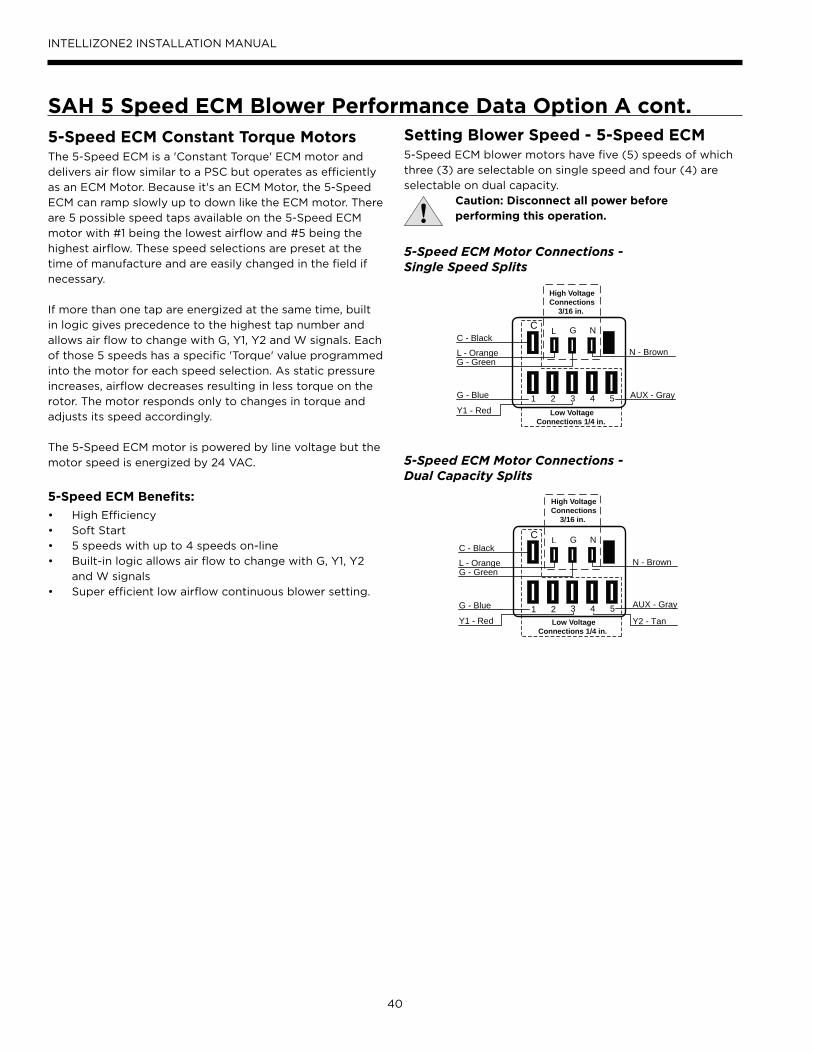
40
INTELLIZONE2 INSTALLATION MANUAL
SAH 5 Speed ECM Blower Performance Data Option A cont.5-Speed ECM Constant Torque MotorsThe 5-Speed ECM is a 'Constant Torque' ECM motor and
delivers air flow similar to a PSC but operates as efficiently
as an ECM Motor. Because it's an ECM Motor, the 5-Speed
ECM can ramp slowly up to down like the ECM motor. There
are 5 possible speed taps available on the 5-Speed ECM
motor with #1 being the lowest airflow and #5 being the
highest airflow. These speed selections are preset at the
time of manufacture and are easily changed in the field if
necessary.
If more than one tap are energized at the same time, built
in logic gives precedence to the highest tap number and
allows air flow to change with G, Y1, Y2 and W signals. Each
of those 5 speeds has a specific 'Torque' value programmed
into the motor for each speed selection. As static pressure
increases, airflow decreases resulting in less torque on the
rotor. The motor responds only to changes in torque and
adjusts its speed accordingly.
The 5-Speed ECM motor is powered by line voltage but the
motor speed is energized by 24 VAC.
5-Speed ECM Benefits:
• High Efficiency
• Soft Start
• 5 speeds with up to 4 speeds on-line
• Built-in logic allows air flow to change with G, Y1, Y2
and W signals
• Super efficient low airflow continuous blower setting.
Setting Blower Speed - 5-Speed ECM5-Speed ECM blower motors have five (5) speeds of which
three (3) are selectable on single speed and four (4) are
selectable on dual capacity.
Caution: Disconnect all power before performing this operation.
L G NC
High VoltageConnections
3/16 in.
1 2 3 4 5G - Blue
Y1 - Red
AUX - Gray
C - Black
L - OrangeG - Green
N - Brown
Low VoltageConnections 1/4 in.
L G NC
1 2 3 4 5 AUX - GrayG - Blue
Y1 - Red Y2 - Tan
C - Black
L - OrangeG - Green
N - Brown
High VoltageConnections
3/16 in.
Low VoltageConnections 1/4 in.
5-Speed ECM Motor Connections - Single Speed Splits
5-Speed ECM Motor Connections - Dual Capacity Splits
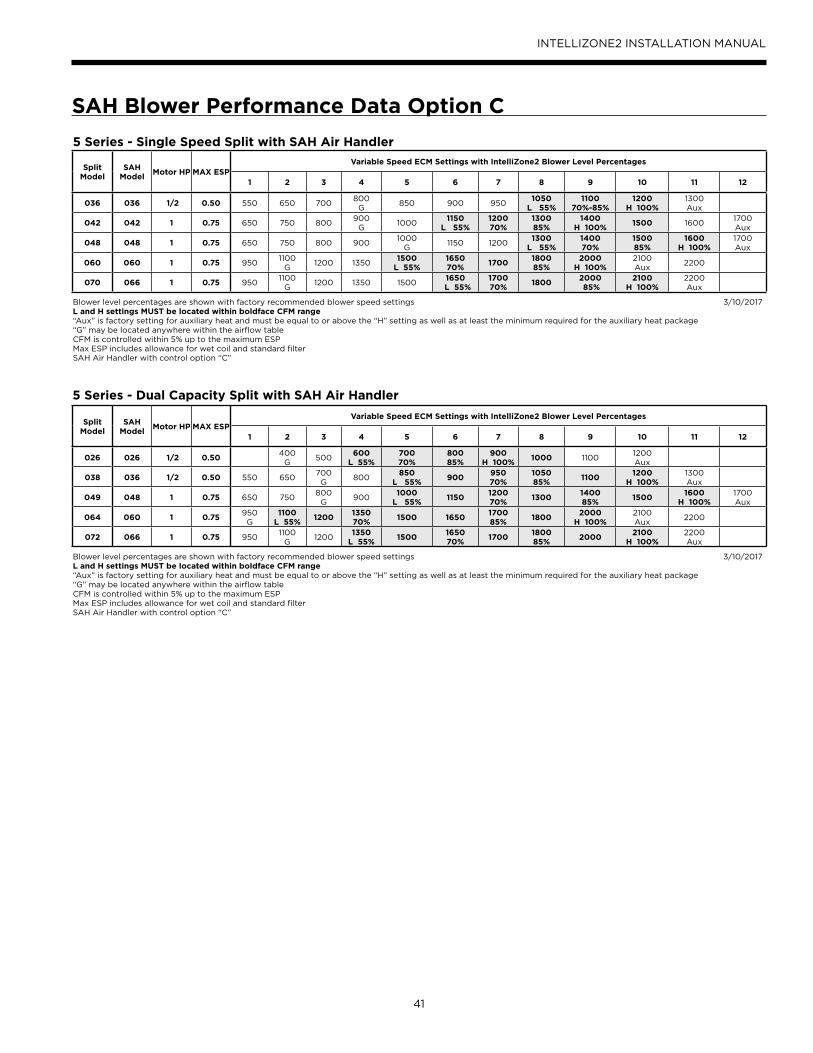
41
INTELLIZONE2 INSTALLATION MANUAL
SAH Blower Performance Data Option C
5 Series - Single Speed Split with SAH Air Handler
Split Model
SAH Model
Motor HP MAX ESPVariable Speed ECM Settings with IntelliZone2 Blower Level Percentages
1 2 3 4 5 6 7 8 9 10 11 12
036 036 1/2 0.50 550 650 700800
G850 900 950
1050 L 55%
1100 70%-85%
1200 H 100%
1300 Aux
042 042 1 0.75 650 750 800900
G1000
1150 L 55%
1200 70%
1300 85%
1400 H 100%
1500 16001700 Aux
048 048 1 0.75 650 750 800 9001000
G1150 1200
1300 L 55%
1400 70%
1500 85%
1600 H 100%
1700 Aux
060 060 1 0.75 9501100
G1200 1350
1500 L 55%
1650 70%
17001800 85%
2000 H 100%
2100 Aux
2200
070 066 1 0.75 950 1100
G1200 1350 1500
1650 L 55%
1700 70%
18002000 85%
2100 H 100%
2200 Aux
Blower level percentages are shown with factory recommended blower speed settingsL and H settings MUST be located within boldface CFM range“Aux” is factory setting for auxiliary heat and must be equal to or above the “H” setting as well as at least the minimum required for the auxiliary heat package“G” may be located anywhere within the airflow tableCFM is controlled within 5% up to the maximum ESPMax ESP includes allowance for wet coil and standard filterSAH Air Handler with control option “C”
3/10/2017
5 Series - Dual Capacity Split with SAH Air Handler
Split Model
SAH Model
Motor HP MAX ESPVariable Speed ECM Settings with IntelliZone2 Blower Level Percentages
1 2 3 4 5 6 7 8 9 10 11 12
026 026 1/2 0.50400
G500
600 L 55%
700 70%
800 85%
900 H 100%
1000 11001200 Aux
038 036 1/2 0.50 550 650700
G800
850 L 55%
900950 70%
1050 85%
11001200
H 100%1300 Aux
049 048 1 0.75 650 750800
G900
1000 L 55%
11501200 70%
13001400 85%
15001600
H 100%1700 Aux
064 060 1 0.75950 G
1100 L 55%
12001350 70%
1500 16501700 85%
18002000
H 100%2100 Aux
2200
072 066 1 0.75 9501100
G1200
1350 L 55%
15001650 70%
17001800 85%
20002100
H 100%2200 Aux
Blower level percentages are shown with factory recommended blower speed settingsL and H settings MUST be located within boldface CFM range“Aux” is factory setting for auxiliary heat and must be equal to or above the “H” setting as well as at least the minimum required for the auxiliary heat package“G” may be located anywhere within the airflow tableCFM is controlled within 5% up to the maximum ESPMax ESP includes allowance for wet coil and standard filterSAH Air Handler with control option “C”
3/10/2017
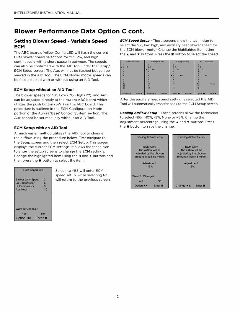
42
INTELLIZONE2 INSTALLATION MANUAL
Blower Performance Data Option C cont.
ECM Speed Info
1▶ 2 ◀ G 3 4 5 6 7 8 9 10 11 12
Option ◀▶ Enter ◙
ECM Speed Info
1 2 G▶ 3 ◀ Lo 4 5 6 7 8 9 10 11 12
Option ◀▶ Enter ◙
ECM Speed Info
1 2 G 3 Lo 4 5▶ 6 ◀ Hi 7 8 9 10 11 12
Option ◀▶ Enter ◙
ECM Speed Info
1 2 G 3 Lo 4 5 6 Hi 7 8 9▶10 ◀ Aux 11 12
Option ◀▶ Enter ◙
ECM Speed Info
Blower Only Speed 3Lo Compressor 6Hi Compressor 9Aux Heat 10
Want To Change?
YesOption ◀▶
NoEnter ◙
Cooling Airflow Setup
--- ECM Only ---The airflow will be
adjusted by the chosenamount in cooling mode.
Adjustment:-15%
Want To Change?
Yes Option ◀▶
No Enter ◙
Cooling Airflow Setup
--- ECM Only ---The airflow will be
adjusted by the chosenamount in cooling mode.
Adjustment:-15%
Change ▼▲ Enter ◙
Setting Blower Speed - Variable Speed ECM The ABC board’s Yellow Config LED will flash the current
ECM blower speed selections for “G”, low, and high
continuously with a short pause in between. The speeds
can also be confirmed with the AID Tool under the Setup/
ECM Setup screen. The Aux will not be flashed but can be
viewed in the AID Tool. The ECM blower motor speeds can
be field adjusted with or without using an AID Tool.
ECM Setup without an AID Tool
The blower speeds for “G”, Low (Y1), High (Y2), and Aux
can be adjusted directly at the Aurora ABC board which
utilizes the push button (SW1) on the ABC board. This
procedure is outlined in the ECM Configuration Mode
portion of the Aurora ‘Base’ Control System section. The
Aux cannot be set manually without an AID Tool.
ECM Setup with an AID Tool
A much easier method utilizes the AID Tool to change
the airflow using the procedure below. First navigate to
the Setup screen and then select ECM Setup. This screen
displays the current ECM settings. It allows the technician
to enter the setup screens to change the ECM settings.
Change the highlighted item using the ◀ and ▶ buttons and
then press the ◙ button to select the item.
Selecting YES will enter ECM
speed setup, while selecting NO
will return to the previous screen.
ECM Speed Setup - These screens allow the technician to
select the “G”, low, high, and auxiliary heat blower speed for
the ECM blower motor. Change the highlighted item using
the ▲ and ▼ buttons. Press the ◙ button to select the speed.
After the auxiliary heat speed setting is selected the AID
Tool will automatically transfer back to the ECM Setup screen.
Cooling Airflow Setup - These screens allow the technician
to select -15%, -10%, -5%, None or +5%. Change the
adjustment percentage using the ▲ and ▼ buttons. Press
the ◙ button to save the change.

43
INTELLIZONE2 INSTALLATION MANUAL
Wiring SchematicSplit Units
A+
R
C
B-
P11 –
Zon
e 1Ma
sterS
tat
A+
R
C
B-
P12 –
Zon
e 2
A+
R
C
B-
P13 –
Zon
e 3
A+
R
C
B-
P14 –
Zon
e 4
A+
R
C
B-
P15 –
Zon
e 5
A+
R
C
B-
P16 –
Zon
e 6
A+
R
C
B-
P3 –
Maste
rStat
Loca
l
C
B-
A+
R
P17 –
Hea
t Pum
p
NO NO
NCCom
Close
Zone 1 Dmpr
Open
P5
NO NO
NCCom
Close
Zone 2 Dmpr
Open
P6
NO NO
NCCom
Close
Zone 3 Dmpr
Open
P7
NO NO
NCCom
Close
Zone 4 Dmpr
Open
P8
NO NO
NCCom
Close
Zone 5 Dmpr
Open
P9
NO NO
NCCom
Close
Zone 6 Dmpr
Open
P10
LAS – Outdoor Air Sensor
P1
G G G
RR B Y
G G G
Zone 1
Zone 2
Heating Cooling
Zone 3
Zone 4 Zone 6
Zone 5
FanAlarm/Status
R
C
P18Damper Power
F1 DamperFuse
F2 Relay Board Fuse
IntelliZone2 Relay Board
DX+
R
C
DX-
Zone
1Ma
sterS
tatMasterStat
A+
R
C
B-
Zone
3 St
atOn32 1
Zone 3 code shown
A+
R
C
B-
Zone
5 St
atOn32 1
Zone 5 code shown
ZoneStat
SensorStat/SensorStat- Remote-Kit
MasterStat is always Zone 1
+
R
C
-
P7 -
Zone
Aurora AXB or Air Handler AHB
Aurora ABC
Split Heat Pump
For Temporary Config or T-ShootZ2TK Kit
Damper Transformer
24V
Blue – 240V
Black - Com
Red – 208V
2-Wire Damper
1-Com
3-Close
2-Open
Drive Close/Spring Open
Drive Open/Drive Close
3-Wire Damper
Zone ID must be set for each Zone 2-6. ID can be confirmed on ZoneStat by pressing cancel button for 5 sec. ID shown on display. See Zone ID Codes.
Zone ID must be set for each Zone 2-6. ID cannot be confirmed on Zone Sensor Stat. See Zone ID Codes.
AID Tool
TSU02Optional Outdoor
Temp Sensor
Black/White
Yellow5A Fuse
3A Fuse
Light emitting diode - Green
Polarized connector
Low voltage wiring
Internal junction
Fuse
Legend
Relay Contacts-N.O., N.C.
G
132PScrew Terminal Strip
Com
Close
Open
On32 1
On32 1
On32 1
Zone 4 Zone 5Zone 3On
32 1
Zone 2On
32 1
Zone 6
Zone ID Codes
1) Zone ID must be set for each Zone 2-6. ID can be confirmed on ZoneStat by pressing cancel button for 5 sec. ID shown on display.2) Small screw driver can be used to set ID thru protective plastic skin!3) MasterStat always Zone 1. Zone ID not necessary4) TPCC32U01 zone is set thru touchscreen.
NOTES:
R
+
-
C
Harness Supplied withIntelliZone2 then wire
nut to stat wire
Wire nut
1-Com
2-Close
S1
S2 Optio
nal
Remo
te Se
nsor
Microprocessor and other
Components
TPCC32U01 DX+
R
C
DX-(Note 4)
S1
S2 Optio
nal
Remo
te Se
nsor
Note: Shorting a thermostat R/C input
will blow the ABC fuse not this fuse
75VA kit mounted in heat pump or Air Handler (PN ZTK240)

44
INTELLIZONE2 INSTALLATION MANUAL
Wiring Schematic cont.Split Units AXB and 5 Speed ECM
CFM
P13
P4
SW1
P5JW2
P9
LO
O/B
Y2WDH
P8 P7
RS485 NET RS485 NET
P6
RS485 EXP
P3
SW2
On
Future Use L Output Type
CC – Dual/SingleAcc – Dip 5Acc – Dip 4
RV – B/OFP2 – 15°F/30°FFP1 – 15°F/30°F
Com1LED5
Com2LED5
Test Mode
F1-3A
P1
C
PWM
12345678
ALMALGACC COMACC NOACC NC
RC
GY1
EH2CEH1CCOC R - +C R - +
Off
FaultLED1
R
StatusLED3
ConfigLED2
CC2 CC F C R F FG CC CCGCC2HI
CC2LO
CC2G REV REV FP1 FP1 FP2 FP2 LPS LPS HPS HPS
Aurora Base Control(ABC) in Compressor Section
K1-RV Relay
K2-CC Relay
K3-CC2 Relay
K4-Fan RelayK5-Alarm Relay
K6-Acc Relay
F
R
C
CCGY1C
R
ESLS
P2
EH1
YG G
G
To TB R
To TB C
To TB W1
To TB Y2
To TB Y1
To TB G
A+
R
C
B- P17 –
Hea
t Pum
p+
R
C
-
P7 -
Zone
Aurora AXB in Compressor Section
R
+
-
C
Harness Supplied withIntelliZone2 then wire
nut to stat wire
IntelliZone2 Relay Panel
P9
ABCC R (-) (+)
+5
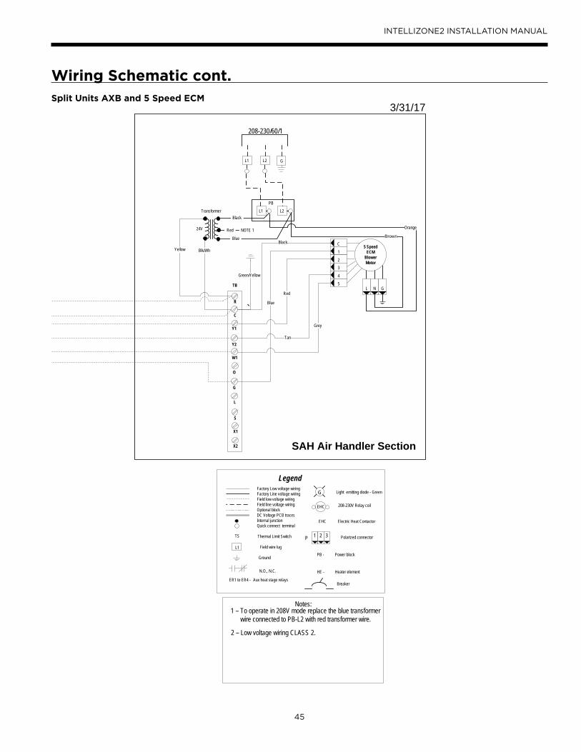
45
INTELLIZONE2 INSTALLATION MANUAL
GL2L1
208-230/60/1
Light emitting diode - Green
208-230V Relay coil
Electric Heat Contactor
Polarized connector
Factory Low voltage wiringFactory Line voltage wiringField low voltage wiringField line voltage wiringOptional blockDC Voltage PCB tracesInternal junctionQuick connect terminal
Thermal Limit Switch
Field wire lug
Ground
HE -
PB -
Heater element
Power block
Legend
N.O., N.C.
G
L1
ER1 to ER4 - Aux heat stage relays
1 2 3P
EHC
EHC
Breaker
TS
Notes:1 – To operate in 208V mode replace the blue transformer wire connected to PB-L2 with red transformer wire.
2 – Low voltage wiring CLASS 2.
SAH Air Handler Section
Transformer
Blk/WhYellow
24V
L2L1
PB
Black
Blue
Red NOTE 1 Orange
Brown
1
2
3
L N G
5 SpeedECM
BlowerMotor
C
4
5
O
C
Y1
G
S
W1
L
X2
X1
R
Y2
TB
Black
Blue
Red
Tan
Grey
`
3/31/17
Green/Yellow
Wiring Schematic cont.Split Units AXB and 5 Speed ECM

46
INTELLIZONE2 INSTALLATION MANUAL
IntelliZone2 with AHB and Variable Speed ECM
IntelliZone2 with Split ABC/AXB and SAH AHB and Variable Speed ECM
Wiring Schematic cont.

47
INTELLIZONE2 INSTALLATION MANUAL
Revision Guide
Pages: Description: Date: By:
Misc. Updated Schematics, Added new Air Handler information 10 Mar 2017 JM
Misc. Minor Revisions & Added SensorState Remote Kit 24 May 2016 JM
Misc. Minor Revisions to Configuration section 03 Nov 2015 MA
18 Added ‘Dual Fuel’ Description 07 April 2015 MA
All Minor Revisions, AWL Information Added 12 Feb 2015 MA
All Software Update 04 June 2014 MA
4 Added Outdoor Sensor to Components 29 Apr 2014 DS
9 Updated Damper Wiring Diagrams 29 Apr 2014 DS
15-16 Updated Staging Descriptions and Features 29 Apr 2014 DS
23 Updated Dual Capacity Blower Table 29 Apr 2014 DS
29 Revision Table Added 29 Apr 2014 DS

Manufactured by
WaterFurnace International, Inc.
9000 Conservation Way
Fort Wayne, IN 46809
www.waterfurnace.com
©2017 WaterFurnace International, Inc., 9000 Conservation Way, Fort Wayne, IN 46809-9794. WaterFurnace has a policy of continual product research and development and reserves the right to change design and specifi cations without notice. IM1578EW 05/17
Product: IntelliZone2
Type: Comfort Zoning System
Size: Six Zone Capability
Document: Installation Manual
*IM1578EW*