Intelligent WAN Technology Design Guide - January 2015 - CVD ...
222
Transcript of Intelligent WAN Technology Design Guide - January 2015 - CVD ...


Intelligent WANTechnology Design Guide
January 2015

Table of Contents
Table of ContentsPreface ..................................................................................................................................................... 1
CVD Navigator .......................................................................................................................................... 2
Use Cases ................................................................................................................................................2
Scope .......................................................................................................................................................2
Proficiency ................................................................................................................................................2
Introduction .............................................................................................................................................. 3
Technology Use Cases .............................................................................................................................3Use Case: Secure Site-to-Site WAN Communications .......................................................................3
Cisco Intelligent WAN Overview ................................................................................................................4Transport Independence ......................................................................................................................4Intelligent Path Control ........................................................................................................................5Application Optimization .......................................................................................................................5Secure Connectivity .............................................................................................................................5
Design Overview .......................................................................................................................................5Transport-Independent WAN Design ...................................................................................................5IP Multicast .........................................................................................................................................15Quality of Service ...............................................................................................................................15Intelligent Path Control .......................................................................................................................16
Deploying the Cisco Intelligent WAN ....................................................................................................... 18
Overall IWAN Architecture Design Goals .................................................................................................18Overlay Transport (DMVPN) ...............................................................................................................18IP Routing (EIGRP) ..............................................................................................................................18Quality of Service ..............................................................................................................................18Path Optimization (Performance Routing) ...........................................................................................19LAN Access .......................................................................................................................................19Design Parameters .............................................................................................................................19

Table of Contents
Deploying the Transport Independent Design ......................................................................................... 20
Design Overview .....................................................................................................................................20DMVPN Hub Routers ..........................................................................................................................20Remote Sites—DMVPN Spoke Router Selection .................................................................................20VRFs and Front Door VRF ..................................................................................................................21Design Details ....................................................................................................................................23EIGRP .................................................................................................................................................24Encryption ..........................................................................................................................................24DMVPN ..............................................................................................................................................25
Deployment Details .................................................................................................................................27Configuring an IOS Certificate Authority ............................................................................................27Configuring DMVPN Hub Router ........................................................................................................34Configuring the Firewall and DMZ Switch ..........................................................................................55Configuring Remote-Site DMVPN Router ...........................................................................................65Adding Second DMVPN for a Single-Router Remote Site ..................................................................88Adding LTE fallback DMVPN for a single-router remote site ...............................................................99Modifying the First Router for Dual Router Design ............................................................................ 114Configuring Remote-Site DMVPN Router (Router 2) ........................................................................ 119
Deploying an IWAN Remote-Site Distribution Layer .............................................................................. 146Connecting Remote-site Router to Distribution Layer ......................................................................146Connecting Remote-Site Router to Distribution Layer (Router 2) .........................................................................................................................................153
Deploying IWAN Quality of Service ....................................................................................................... 158Configuring QoS for DMVPN Routers ...............................................................................................158Applying DMVPN QoS Policy to DMVPN Hub Routers .....................................................................164Applying QoS Configurations to Remote Site Routers ......................................................................168
Deploying IWAN Performance Routing...................................................................................................173Configuring PfR Hub Master Controller ............................................................................................175Configuring Performance Routing for Hub Location .........................................................................181Configuring PfR for Remote Site Locations ......................................................................................189
Deploying IWAN Monitoring .................................................................................................................. 202Configuring Flexible NetFlow for IWAN Monitoring ...........................................................................202
Appendix A: Product List .......................................................................................................................210
Appendix B: Technical Feature Supplement ...........................................................................................213
Front Door VRF for DMVPN ...................................................................................................................213
Appendix C: Device Configuration Files .................................................................................................217

Preface January 20151
PrefaceCisco Validated Designs (CVDs) present systems that are based on common use cases or engineering priorities. CVDs incorporate a broad set of technologies, features, and applications that address customer needs. Cisco engineers have comprehensively tested and documented each design in order to ensure faster, more reliable, and fully predictable deployment.
CVDs include two guide types that provide tested design details:
• Technology design guides provide deployment details, information about validated products and software, and best practices for specific types of technology.
• Solution design guides integrate existing CVDs but also include product features and functionality across Cisco products and sometimes include information about third-party integration.
Both CVD types provide a tested starting point for Cisco partners or customers to begin designing and deploying systems.
CVD Foundation SeriesThis CVD Foundation guide is a part of the January 2015 Series. As Cisco develops a CVD Foundation series, the guides themselves are tested together, in the same network lab. This approach assures that the guides in a series are fully compatible with one another. Each series describes a lab-validated, complete system.
The CVD Foundation series incorporates wired and wireless LAN, WAN, data center, security, and network management technologies. Using the CVD Foundation simplifies system integration, allowing you to select solutions that solve an organization’s problems—without worrying about the technical complexity.
To ensure the compatibility of designs in the CVD Foundation, you should use guides that belong to the same release. For the most recent CVD Foundation guides, please visit the CVD Foundation web site.
Comments and QuestionsIf you would like to comment on a guide or ask questions, please use the feedback form.

CVD Navigator January 20152
CVD NavigatorThe CVD Navigator helps you determine the applicability of this guide by summarizing its key elements: the use cases, the scope or breadth of the technology covered, the proficiency or experience recommended, and CVDs related to this guide. This section is a quick reference only. For more details, see the Introduction.
Use CasesThis guide addresses the following technology use cases:
• Use Case: Secure Site-to-Site WAN Communications — This guide helps organizations connect remote sites over private (MPLS VPN) and public (Internet) IP networks, efficiently and securely.
For more information, see the “Use Cases” section in this guide.
ScopeThis guide covers the following areas of technology and products:
• Dynamic Multipoint Virtual Private Network (DMVPN) design and deployment over public and private WAN transport
• Transport Independent Design (TID) provides capabilities for easy multi-homing over any carrier service offering, including MPLS, broadband, and cellular 3G/4G/LTE
• Intelligent Path Control with Cisco Performance Routing (PfR) improves application delivery and WAN efficiency
• Secure connectivity protects the corporate communications and offloads user traffic directly to the Internet
• WAN quality of server (QoS) design and configuration
For more information, see the “Design Overview” section in this guide.
ProficiencyThis guide is for people with the following technical proficiencies or equivalent experience:
• CCNP Routing and Switching
• CCNP Security
To view the related CVD guides, click the titles or visit the CVD Foundation web site.
Related CVD Guides
VALIDATEDDESIGN
Firewall and IPS TechnologyDesign Guide
VALIDATEDDESIGN
MPLS WAN TechnologyDesign Guide
VALIDATEDDESIGN
VPN WAN TechnologyDesign Guide

Introduction January 20153
IntroductionThe Cisco Intelligent WAN (IWAN) solution provides design and implementation guidance for organizations looking to deploy wide area network (WAN) transport with a transport-independent design (TID), intelligent path control, application optimization, and secure encrypted communications between branch locations while reducing the operating cost of the WAN. IWAN takes full advantage of cost-effective transport services in order to increase bandwidth capacity without compromising performance, reliability, or security of collaboration or cloud-based applications.
Technology Use CasesOrganizations require the WAN to provide sufficient performance and reliability for the remote-site users to be effective in supporting the business. Although most of the applications and services that the remote-site worker uses are centrally located, the WAN design must provide the workforce with a common resource-access experience, regardless of location.
Carrier-based MPLS service is not always available or cost-effective for an organization to use exclusively for remote-site WAN connectivity. There are multiple WAN transport offerings that can be used simultaneously to create a robust, secure, and cost-effective WAN, including MPLS VPNs, Internet, Cellular (3G/LTE), and Carrier Ethernet. Internet-based IP VPNs offer attractive bandwidth pricing and can augment premium MPLS offerings or replace MPLS in some scenarios. A flexible network architecture should include all common WAN transport offerings as options without significantly increasing the complexity of the overall design.
While Internet IP VPN networks present an attractive option for effective WAN connectivity, anytime an organization sends data across a public network there is risk that the data will be compromised. Loss or corruption of data can result in a regulatory violation and can present a negative public image, either of which can have significant financial impact on an organization. Secure data transport over public networks like the Internet requires adequate encryption to protect business information.
Use Case: Secure Site-to-Site WAN Communications This guide helps organizations connect remote sites over private (MPLS VPN) and public (Internet) IP networks, efficiently and securely.
This design guide enables the following network capabilities:
• Secure, encrypted communications solutions for up to 2000 locations by using a dynamic multipoint VPN (DMVPN) IPsec tunnel overlay configuration
• A multi-homed active-active connectivity solution for resiliency and efficient use of all WAN bandwidth, using single or dual routers in remote locations
• Support for IP Multicast and replication performed on core, hub-site routers
• Compatibility with public Internet networks where network address translation (NAT) is implemented

Introduction January 20154
Cisco Intelligent WAN OverviewWith the advent of globalization, WANs have become a major artery for communication between remote offices and customers in any corner of the world. Additionally, with data center consolidation, applications are moving to centralized data centers and clouds. WANs now play an even more critical role, because business survival is dependent on the availability and performance of the network.
Until now, the only way to get reliable connectivity with predictable performance was to take advantage of a private WAN using MPLS or leased line service. However, carrier-based MPLS and leased line services can be expensive and are not always cost-effective for an organization to use for WAN transport in order to support growing bandwidth requirements for remote-site connectivity. Organizations are looking for ways to lower operating budget while adequately providing the network transport for a remote site.
As bandwidth demands have increased, the Internet has become a much more stable platform, and the price-to-performance gains are very attractive. However, businesses are primarily deploying “Internet as WAN” in their smaller sites or as a backup path because of the risks. Now this cost-effective, performance-enhancing opportunity can be realized at all your branch offices with Cisco IWAN.
Cisco IWAN enables organizations to deliver an uncompromised experience over any connection. With Cisco IWAN IT organizations can provide more bandwidth to their branch office connections by using less expensive WAN transport options without affecting performance, security, or reliability. With the IWAN solution, traffic is dynamically routed based on application service-level agreement (SLA), endpoint type, and network conditions in order to deliver the best quality experience. The realized savings from IWAN not only pays for the infrastructure upgrades, but also frees resources for business innovation.
Figure 1 - Cisco IWAN solution components
Transport IndependenceUsing DMVPN, IWAN provides capabilities for easy multi-homing over any carrier service offering, including MPLS, broadband, and cellular 3G/4G/LTE. More importantly, the design simplifies the routing design with a single routing control plane and minimal peering to providers, making it easy for organizations to mix and match and change providers and transport options. Two or more WAN transport providers are recommended in order to increase network availability up to 99.999%. Additionally, the Cisco DMVPN solution provides an industry-proven and U.S. government FIPS 140-2 certified IPsec solution for data privacy and integrity protection, as

Introduction January 20155
well as automatic site-to-site IP security (IPsec) tunnels. These tunnels can be set up using pre-shared keys or using a public key infrastructure with a certificate authority in the demilitarized zone (DMZ) in order to enroll and authorize the use of keys between routers.
Intelligent Path Control Cisco Performance Routing (PfR) improves application delivery and WAN efficiency. PfR dynamically controls data packet forwarding decisions by looking at application type, performance, policies, and path status. PfR monitors the network performance—jitter, packet loss, and delay—and makes decisions to forward critical applications over the best-performing path based on the application policy. Cisco PfR can intelligently load-balance traffic to efficiently use all available WAN bandwidth. IWAN intelligent path control is the key to providing a business-class WAN over Internet transport.
Application OptimizationCisco Application Visibility and Control (AVC) and Cisco Wide Area Application Services (WAAS) provide application performance visibility and optimization over the WAN. With applications becoming increasingly opaque due to the increased reuse of well-known ports such as HTTP (port 80), static port classification of applications is no longer sufficient. Cisco AVC provides application awareness with deep packet inspection of traffic in order to identify and monitor applications’ performance. Cisco AVC allows IT to determine what traffic is running across the network, tune the network for business-critical services, and resolve network problems. With increased visibility into the applications on the network, better QoS and PfR policies can be enabled to help ensure that critical applications are properly prioritized across the network. Cisco WAAS provides application-specific acceleration capabilities that improve response times while reducing WAN bandwidth requirements.
Secure ConnectivitySecure connectivity protects the corporate communications and offloads user traffic directly to the Internet. Strong IPsec encryption, zone-based firewalls, and strict access controls are used to protect the WAN over the public Internet. Routing remote-site users directly to the Internet improves public cloud application performance while reducing traffic over the WAN. Cisco Cloud Web Security (CWS) service provides a cloud-based web proxy to centrally manage and secure user traffic accessing the Internet.
Design OverviewThe Cisco Intelligent WAN Design Guide provides a design that enables highly available, secure, and optimized connectivity for multiple remote-site local area networks (LANs).
Transport-Independent WAN DesignA transport-independent design simplifies the WAN deployment by using an IPsec VPN overlay over all WAN transport options including MPLS, Internet, and Cellular (3G/4G). A single VPN overlay reduces routing and security complexity, and provides flexibility in choosing providers and transport options. Cisco DMVPN provides the IWAN IPsec overlay.
DMVPN makes use of multipoint generic routing encapsulation (mGRE) tunnels to interconnect the hub to all of the spoke routers. These mGRE tunnels are also sometimes referred to as DMVPN clouds in this context. This technology combination supports unicast, multicast, and broadcast IP, including the ability to run routing protocols within the tunnels.

Introduction January 20156
Internet as WAN TransportThe Internet is essentially a large-scale public IP WAN composed of multiple interconnected service providers. The Internet can provide reliable high-performance connectivity between various locations, although it lacks any explicit guarantees for these connections. Despite its “best effort” nature, the Internet is a sensible choice for augmenting premium MPLS VPN transports or as a primary WAN transport in some cases. The IWAN architecture leverages two or more providers for resiliency and application availability. Provider path diversity provides the foundation for PfR to route around fluctuations in the providers’ performance.
Internet connections are typically included in discussions relevant to the Internet edge, specifically for the primary site. Remote-site routers also commonly have Internet connections but do not provide the same breadth of services using the Internet. For security and other reasons, Internet access at remote sites is often routed through the primary site.
This design guide uses both MPLS and the Internet for VPN site-to-site connections.
Dynamic Multipoint VPNDMVPN is a solution for building scalable site-to-site VPNs that support a variety of applications. DMVPN is widely used for encrypted site-to-site connectivity over public or private IP networks and can be implemented on all WAN routers used in this design guide.
DMVPN was selected for the secure overlay WAN solution because DMVPN supports on-demand full mesh connectivity over any carries transport with a simple hub-and-spoke configuration. DMVPN also supports spoke routers that have dynamically assigned IP addresses.
DMVPN makes use of multipoint generic routing encapsulation (mGRE) tunnels to interconnect the hub to all of the spoke routers. These mGRE tunnels are also sometimes referred to as DMVPN clouds in this context. This technology combination supports unicast, multicast, and broadcast IP, including the ability to run routing protocols within the tunnels.
EthernetThe WAN transports mentioned previously use Ethernet as a standard media type. Ethernet is becoming a dominant carrier handoff in many markets and it is relevant to include Ethernet as the primary media in the tested architectures. Much of the discussion in this guide can also be applied to non-Ethernet media (such as T1/E1, DS-3, OC-3, and so on), but they are not explicitly discussed.
WAN-Aggregation DesignsThis guide describes two IWAN design models.
The first design model is the IWAN Hybrid, which uses MPLS paired with Internet VPN as WAN transports. In this design model, the MPLS WAN can provide more bandwidth for the critical classes of services needed for key applications and can provide SLA guarantees for these applications. The second design model is the IWAN Dual Internet, which uses a pair of Internet service providers to further reduce cost while maintaining a high level of resiliency for the WAN. A third design model, the IWAN Dual MPLS, is not covered in this guide.

Introduction January 20157
Figure 2 - Cisco IWAN design models
The IWAN WAN-aggregation (hub) designs for both design models include two WAN edge routers.
When WAN aggregation routers are referred to in the context of the connection to a carrier or service provider, they are typically known as customer edge (CE) routers. WAN aggregation routers that terminate VPN traffic are referred to as VPN hub routers. In the context of IWAN, a MPLS A CE router is also used as a VPN hub router. Regardless of the design model, the WAN aggregation routers always connect into a pair of distribution layer switches.
Each of the design models is shown with LAN connections into either a collapsed core/distribution layer or a dedicated WAN distribution layer. From the WAN-aggregation perspective, there are no functional differences between these two methods.
In all of the WAN-aggregation designs, tasks such as IP route summarization are performed at the distribution layer. There are other various devices supporting WAN edge services, and these devices should also connect into the distribution layer.
The characteristics of each design are discussed in the following sections.

Introduction January 20158
IWAN Hybrid Design ModelThe IWAN Hybrid design model:
• Has a single MPLS VPN carrier.
• Uses a single Internet carrier.
• Uses front-door virtual routing and forwarding (FVRF) on both MPLS and Internet links, with static default routing within the FVRF.
FVRF provides control plane separation from the providers and an additional security layer between inside and outside networks.
Figure 3 - WAN aggregation: IWAN hybrid design model
WAN DistributionLayer
Core Layer
DMVPN 21
21
9
MPLS
DMVPN 1
Internet EdgeDMVPN Hub
Router (MPLS)DMVPN HubRouter (INET)
INET
In both the IWAN Hybrid and IWAN Dual Internet design models, the DMVPN hub routers connect to the Internet indirectly through a firewall DMZ interface contained within the Internet edge. For details about the connection to the Internet, see the Firewall and IPS Technology Design Guide. The VPN hub routers are connected into the firewall DMZ interface, rather than connected directly with Internet service-provider routers. A firewall connection is typically not used when the VPN hub router connects to a MPLS carrier.

Introduction January 20159
IWAN Dual Internet Design ModelThe IWAN Dual Internet design model:
• Uses two Internet carriers.
• Uses Front Door VRF (FVRF) on both Internet links, with static default routing within the FVRF.
Figure 4 - WAN aggregation: IWAN dual Internet design model
WAN DistributionLayer
Core Layer
DMVPN 4
12
20
DMVPN 3
Internet EdgeDMVPN Hub
Router (INET 1)DMVPN HubRouter (INET 2)
INET
ISP A / ISP B
WAN Remote-Site DesignsThis guide documents multiple WAN remote-site designs, and they are based on various combinations of WAN transports mapped to the site specific requirements for service levels and redundancy.
Figure 5 - WAN remote-site design options
Link Resiliency with Dual Routers
Link Resiliency
12
21
IWAN Hybrid IWAN Dual Internet
MPLS Internet Internet Internet
MPLS InternetInternet Internet

Introduction January 201510
The remote-site designs include single or dual WAN edge routers. The remote-site routers are DMVPN spokes to the primary site hubs.
Most remote sites are designed with a single router WAN edge; however, certain remote-site types require a dual router WAN design. Dual router candidate sites include regional office or remote campus locations with large user populations or sites with business critical needs that justify additional redundancy to remove single points of failure.
The overall WAN design methodology is based on a primary WAN-aggregation site design that can accommodate all of the remote-site types that map to the various link combinations listed in the following table.
Table 1 - WAN remote-site transport options
WAN remote-site routers WAN transports Primary transport Secondary transport
Single Dual MPLS VPN Internet
Dual Dual MPLS VPN Internet
Single Dual Internet Internet
Dual Dual Internet Internet
This design guide also includes information for adding an LTE fallback DMVPN for a single-router remote site.
Table 2 - WAN remote-site transport options with LTE fallback
WAN remote-site routers WAN transportsPrimary transport
Secondary transport
Tertiary transport
Single Dual w/ fallback MPLS VPN Internet 4G LTE
Single Dual w/ fallback Internet Internet 4G LTE
The modular nature of the IWAN network design enables you to create design elements that can be replicated throughout the network.
The WAN-aggregation designs and all of the WAN remote-site designs are standard building blocks in the overall design. Replication of the individual building blocks provides an easy way to scale the network and allows for a consistent deployment method.
WAN/LAN InterconnectionThe primary role of the WAN is to interconnect primary site and remote-site LANs. The LAN discussion within this guide is limited to how the WAN-aggregation site LAN connects to the WAN-aggregation devices and how the remote-site LANs connect to the remote-site WAN devices. Specific details regarding the LAN components of the design are covered in the Campus Wired LAN Technology Design Guide.

Introduction January 201511
At remote sites, the LAN topology depends on the number of connected users and physical geography of the site. Large sites may require the use of a distribution layer to support multiple access layer switches. Other sites may only require an access layer switch directly connected to the WAN remote-site routers. The variants that are tested and documented in this guide are shown in the following table.
Table 3 - WAN remote-site LAN options
WAN remote-site routers WAN transports LAN topology
Single Dual Access only
Distribution/Access
Dual Dual Access only
Distribution/Access
WAN Remotes Sites—LAN TopologyFor consistency and modularity, all WAN remote sites use the same VLAN assignment scheme, which is shown in the following table. This design guide uses a convention that is relevant to any location that has a single access switch and this model can also be easily scaled to additional access closets through the addition of a distribution layer.
Table 4 - WAN remote-sites: VLAN assignment
VLAN Usage Layer 2 access Layer 3 distribution/access
VLAN 64 Data 1 Yes —
VLAN 69 Voice 1 Yes —
VLAN 99 Transit Yes
(dual router only)
Yes
(dual router only)
VLAN 50 Router Link (1) — Yes
VLAN 54 Router Link (2) — Yes
(dual router only)
Layer 2 AccessWAN remote sites that do not require additional distribution layer routing devices are considered to be flat or from a LAN perspective they are considered un-routed Layer 2 sites. All Layer 3 services are provided by the attached WAN routers. The access switches, through the use of multiple VLANs, can support services such as data and voice. The design shown in the following figure illustrates the standardized VLAN assignment scheme. The benefits of this design are clear: all of the access switches can be configured identically, regardless of the number of sites in this configuration.
Access switches and their configuration are not included in this guide. The Campus Wired LAN Technology Design Guide provides configuration details on the various access switching platforms.
IP subnets are assigned on a per-VLAN basis. This design only allocates subnets with a 255.255.255.0 netmask for the access layer, even if less than 254 IP addresses are required. (This model can be adjusted as necessary to other IP address schemes.) The connection between the router and the access switch must be configured for 802.1Q VLAN trunking with sub-interfaces on the router that map to the respective VLANs on the switch. The various router sub-interfaces act as the IP default gateways for each of the IP subnet and VLAN combinations.

Introduction January 201512
Figure 6 - WAN remote site with flat layer 2 LAN (single router)
Internet
No HSRPRequired
VLAN 64 - Data
802.1Q VLAN Trunk (64, 69)
VLAN 69 - Voice
21
40
A similar LAN design can be extended to a dual-router edge as shown in the following figure. This design change introduces some additional complexity. The first requirement is to run a routing protocol. You need to configure enhanced interior gateway routing protocol (EIGRP) between the routers.
Because there are now two routers per subnet, a first-hop redundancy protocol (FHRP) must be implemented. For this design, Cisco selected hot standby router protocol (HSRP) as the FHRP. HSRP is designed to allow for transparent failover of the first-hop IP router. HSRP provides high network availability by providing first-hop routing redundancy for IP hosts configured with a default gateway IP address. HSRP is used in a group of routers for selecting an active router and a standby router. When there are multiple routers on a LAN, the active router forwards the packets; the standby router is the router that takes over when the active router fails or when preset conditions are met.
Figure 7 - WAN remote site with flat layer 2 LAN (dual router)
WAN WAN
Active HSRP Router VLAN 64 - Data
VLAN99 - Transit
802.1Q VLAN Trunk (64, 69, 99)
VLAN 69 - Voice
21
41
HSRP VLANs
EIGRP
Enhanced object tracking (EOT) provides a consistent methodology for various router and switching features to conditionally modify their operation based on information objects available within other processes. The objects that can be tracked include interface line protocol, IP route reachability, and IP SLA reachability, as well as several others.
To improve convergence times after a primary WAN failure, HSRP has the capability to monitor the line-protocol status of the DMVPN tunnel interface. This capability allows for a router to give up its HSRP Active role if its DMVPN hub becomes unresponsive, and that provides additional network resiliency.

Introduction January 201513
HSRP is configured to be active on the router with the highest priority WAN transport. EOT of the primary DMVPN tunnel is implemented in conjunction with HSRP so that in the case of WAN transport failure, the standby HSRP router associated with the lower priority (alternate) WAN transport becomes the active HSRP router.
The dual router designs also warrant an additional component that is required for proper routing in certain scenarios. In these cases, a traffic flow from a remote-site host might be sent to a destination reachable via the alternate WAN transport (for example, a dual DMVPN remote site communicating with a DMVPN2-only remote site). The primary WAN transport router then forwards the traffic out the same data interface to send it to the alternate WAN transport router, which then forwards the traffic to the proper destination. This is referred to as hairpinning.
The appropriate method to avoid sending the traffic out the same interface is to introduce an additional link between the routers and designate the link as a transit network (Vlan 99). There are no hosts connected to the transit network, and it is only used for router-router communication. The routing protocol runs between router sub-interfaces assigned to the transit network. No additional router interfaces are required with this design modification because the 802.1Q VLAN trunk configuration can easily accommodate an additional sub-interface.
Distribution and Access LayerLarge remote sites may require a LAN environment similar to that of a small campus LAN that includes a distribution layer and access layer. This topology works well with either a single or dual router WAN edge. To implement this design, the routers should connect via EtherChannel links to the distribution switch. These EtherChannel links are configured as 802.1Q VLAN trunks, to support both a routed point-to-point link to allow EIGRP routing with the distribution switch, and in the dual router design, to provide a transit network for direct communication between the WAN routers.
Figure 8 - IWAN single router remote-site: Connection to distribution layer
12
22
VLAN 50 - Router 1 Link
802.1q Trunk (xx-xx)
802.1q Trunk (50)
802.1q Trunk (xx-xx)

Introduction January 201514
Figure 9 - IWAN dual router remote-site: Connection to distribution layer
VLAN 50 - Router 1 Link
802.1q Trunk(xx-xx)
802.1q Trunk(xx-xx)
802.1q Trunk(50, 99)
802.1q Trunk(54, 99)
VLAN 54 - Router 2 LinkVLAN 99 - Transit 1
22
3
The distribution switch handles all access layer routing, with VLANs trunked to access switches. No HSRP is required when the design includes a distribution layer. A full distribution and access layer design is shown in the following figure.
Figure 10 - IWAN dual router remote-site: Distribution and access layer
VLAN 50 - Router 1 Link
802.1q Trunk(xx-xx)
802.1q Trunk(xx-xx)
802.1q Trunk(50, 99)
802.1q Trunk(54, 99)
VLAN 54 - Router 2 LinkVLAN 99 - Transit 1
22
4
Data
Voice
Data
Voice

Introduction January 201515
IP MulticastIP Multicast allows a single IP data stream to be replicated by the infrastructure (routers and switches) and sent from a single source to multiple receivers. IP Multicast is much more efficient than multiple individual unicast streams or a broadcast stream that would propagate everywhere. IP telephony music on hold (MOH) and IP video broadcast streaming are two examples of IP Multicast applications.
To receive a particular IP Multicast data stream, end hosts must join a multicast group by sending an Internet group management protocol (IGMP) message to their local multicast router. In a traditional IP Multicast design, the local router consults another router in the network acting as a rendezvous point (RP). An RP maps the receivers to active sources so the end hosts can join their streams.
The RP is a control-plane operation that should be placed in the core of the network or close to the IP Multicast sources on a pair of Layer 3 switches or routers. IP Multicast routing begins at the distribution layer if the access layer is Layer 2 and provides connectivity to the IP Multicast RP. In designs without a core layer, the distribution layer performs the RP function.
This design is fully enabled for a single global scope deployment of IP Multicast. The design uses an Anycast RP implementation strategy. This strategy provides load sharing and redundancy in protocol-independent multicast sparse mode (PIM SM) networks. Two RPs share the load for source registration and the ability to act as hot backup routers for each other.
The benefit of this strategy from the WAN perspective is that all IP routing devices within the WAN use an identical configuration referencing the Anycast RPs. IP PIM-SM is enabled on all interfaces including loopbacks, VLANs and sub-interfaces.
Quality of ServiceMost users perceive the network as just a transport utility mechanism to shift data from point A to point B as fast as it can. Many sum this up as just “speeds and feeds.” While it is true that IP networks forward traffic on a best-effort basis by default, this type of routing only works well for applications that adapt gracefully to variations in latency, jitter, and loss. However networks are multiservice by design and support real-time voice and video as well as data traffic. The difference is that real-time applications require packets to be delivered within the specified delay, jitter, and loss parameters.
In reality, the network affects all traffic flows and must be aware of end-user requirements and services being offered. Even with unlimited bandwidth, time-sensitive applications are affected by jitter, delay, and packet loss. Quality of service (QoS) enables a multitude of user services and applications to coexist on the same network.
Within the architecture, there are connectivity options that provide advanced classification, prioritizing, queuing, and congestion-avoidance as part of the integrated QoS in order to help ensure optimal use of network resources. This functionality allows for the differentiation of applications, ensuring that each has the appropriate share of the network resources to protect the user experience and ensure the consistent operations of business critical applications.
QoS is an essential function of the network infrastructure devices used throughout this architecture. QoS enables a multitude of user services and applications, including real-time voice, high-quality video, and delay-sensitive data to coexist on the same network. In order for the network to provide predictable, measurable, and sometimes guaranteed services, it must manage bandwidth, delay, jitter, and loss parameters.
There are twelve common service classes that are grouped together based on interface speed, available queues, and device capabilities. The treatment of the twelve classes can be adjusted according to the policies of your organization. Cisco recommends marking your traffic in a granular manner to make it easier to make the appropriate queuing decisions at different places in the network. The goal of this design is to allow you to enable voice, video, critical data applications, bulk data applications and management traffic on the network, either during the initial deployment or later, with minimal system impact and engineering effort.

Introduction January 201516
The twelve mappings in the following table are applied throughout this design by using an eight-class model in the enterprise and a six-class model in the service provider network.
Table 5 - QoS service class mappings
Service classPer-hop-behavior (PHB)
Differentiated services code point (DSCP) Application examples
Network control CS6 48 EIGRP, OSPF, BGP, HSRP, IKE
VoIP telephony EF 46 Cisco IP Phones (G.711, G.729)
Call signaling CS3 24 SCCP, SIP, H.323
Multimedia conferencing AF4 34, 36, 38 Cisco TelePresence, Jabber, UC Video, WebEx
Real-time interactive CS4 32 Cisco TelePresence (previous)
Multimedia streaming AF3 26, 28, 30 Cisco Digital Media System (VoDs)
Broadcast video CS5 40 Cisco IP Video Surveillance / Cisco Enterprise TV
Transactional data AF2 18, 20, 22 ERP Apps, CRM Apps, Database Apps
Operation, administration, and maintenance (OAM)
CS2 16 SNMP, SSH, Syslog
Bulk data AF1 10, 12, 14 E-mail, FTP, Backup Apps, Content Distribution
Default “best effort” DF 0 Default class
Scavenger CS1 8 YouTube, iTunes, BitTorent, Xbox Live
Per-Tunnel QoS for DMVPNThe Per-Tunnel QoS for DMVPN feature allows the configuration of a QoS policy on a DMVPN hub on a per-tunnel (spoke) basis. This feature allows you to apply a QoS policy on a tunnel instance (per-endpoint or per-spoke basis) in the egress direction for DMVPN hub-to-spoke tunnels. The QoS policy on a tunnel instance allows you to shape the tunnel traffic to individual spokes (parent policy) and to differentiate between traffic classes within the tunnel for appropriate treatment (child policy).
With simplified configurations, the hub site is prevented from sending more traffic than any single remote-site can handle. This ensures high bandwidth hub sites do not overrun remote-sites with lower bandwidth allocations.
Intelligent Path ControlIntelligent path control improves application delivery and WAN efficiency using PfR. PfR uses policies to dynamically control data packet forwarding by looking at application type, performance, and path status. PfR continuously monitors the network performance for jitter, packet loss and delay, and then it makes decisions to forward critical applications over the best performing path based on the application policy. PfR can evenly distribute traffic to maintain equivalent link utilization levels by using an advanced load balancing technique, even over links with differing bandwidth capacities.
Cisco PfR consists of border routers (BRs) that connect to the DMVPN overlay networks for each carrier network and a master controller (MC) application process that enforces policy. The BR collects traffic and path information and sends it to the MC at each site. The MC and BR can be configured on separate routers or the same router as shown in the figures below.
Introduction January 201517
Figure 11 - Cisco Performance Routing: Hub location
WAN DistributionLayer
Core Layer
DMVPN 2
12
25
DMVPN 1
Internet Edge
DMVPN HubRouter (MPLS)
DMVPN HubRouter (INET)
INET
PfR BorderRouters
PfR MasterController
MPLS
Figure 12 - Cisco Performance Routing: Remote site options
1226
MPLS Internet MPLS Internet
BorderRouter
MasterController/
Border Router
DMVPN 2DMVPN 1
Single Router Dual Router
MasterController/
Border Router
IWAN intelligent path control is the key to providing a business-class WAN over an Internet transport.
Deploying the Cisco Intelligent WAN January 201518
Deploying the Cisco Intelligent WAN
Overall IWAN Architecture Design GoalsOverlay Transport (DMVPN)
All remote-site traffic must be encrypted when transported over public IP networks such as the Internet. This design also encrypts traffic over private IP networks such as MPLS and 4G LTE. It is recommended that you enable encryption on DMVPN over all paths in order to ensure consistency in data privacy and operations.
The use of encryption should not limit the performance or availability of a remote-site application and should be transparent to end users.
IP Routing (EIGRP)The design has the following IP routing goals:
• Provide optimal routing connectivity from primary WAN-aggregation sites to all remote locations
• Isolate WAN routing topology changes from other portions of the network
• Ensure active/standby symmetric routing when multiple paths exist, for ease of troubleshooting and to prevent oversubscription of IP telephony call admission control (CAC) limits
• Provide a solid underlying IP routed topology in order to support the Intelligent Path Control provided by Cisco Performance Routing.
• Provide site-site remote routing via the primary WAN-aggregation site (hub-and-spoke model)
• Permit optimal direct site-site remote routing (spoke-to-spoke model)
• Support IP Multicast sourced from the primary WAN-aggregation site
At the WAN remote sites, there is no local Internet access for web browsing or cloud services. This model is referred to as a centralized Internet model. It is worth noting that sites with Internet/DMVPN could potentially provide local Internet capability; however, for this design, only encrypted traffic to other DMVPN sites is permitted to use the Internet link. In the centralized Internet model, a default route is advertised to the WAN remote sites in addition to the internal routes from the data center and campus.
The use of local Internet access is covered separately from this guide.
The network must tolerate single failure conditions including the failure of any single WAN transport link or any single network device at the primary WAN-aggregation site.
Quality of Service The network must ensure that business applications perform across the WAN during times of network congestion. Traffic must be classified and queued and the WAN connection must be shaped to operate within the capabilities of the connection. When the WAN design uses a service provider offering with QoS, the WAN edge QoS classification and treatment must align to the service provider in order to ensure consistent end-to-end QoS treatment of traffic.

Deploying the Cisco Intelligent WAN January 201519
Path Optimization (Performance Routing)The network must protect business critical applications from fluctuating WAN performance by using the best-performing path based on the application policy. The design must also intelligently load-balance traffic in order to reduce an organization’s overall communications expenses by allowing them to use a less expensive Internet transport without negatively affecting their mission critical traffic.
Remote sites classified as single-router, dual-link must be able tolerate the loss of either WAN transport. Remote sites classified as dual-router, dual-link must be able to tolerate the loss of either an edge router or a WAN transport.
LAN AccessAll remote sites support both wired and wireless LAN access.
Design ParametersThis design guide uses certain standard design parameters and references various network infrastructure services that are not located within the WAN. These parameters are listed in the following table.
Table 6 - Universal design parameters
Network service IP address
Domain name cisco.local
Active Directory, DNS server, DHCP server 10.4.48.10
Cisco Secure Access Control System (ACS) 10.4.48.15
Network Time Protocol (NTP) server 10.4.48.17

Deploying the Transport Independent Design January 201520
Deploying the Transport Independent Design
Design OverviewDMVPN Hub Routers
The most critical devices are the WAN routers that are responsible for reliable IP forwarding and QoS. The amount of bandwidth required at each site determines which model of router to use. The IWAN Hybrid and Dual Internet designs both require dual WAN aggregation routers to support the pair of DMVPN clouds that are required in order to provide resilient connections to all of the remote sites.
Cisco ASR 1000 Series Aggregation Services Routers represent the next-generation, modular, services-integrated Cisco routing platform. They are specifically designed for WAN aggregation, with the flexibility to support a wide range of 3- to 16-mpps (millions of packets per second) packet-forwarding capabilities, 2.5- to 200-Gbps system bandwidth performance, and scaling.
The Cisco ASR 1000 Series is fully modular from both hardware and software perspectives, and the routers have all the elements of a true carrier-class routing product that serves both enterprise and service-provider networks.
This design uses the following routers as DMVPN hub routers:
• Cisco ASR 1002-X router configured with an embedded services processor (ESP) default bandwidth of 5 Gbps upgradable with software licensing options to 10 Gbps, 20 Gbps and 36 Gbps.
• Cisco 4451X Integrated Services Router
Remote Sites—DMVPN Spoke Router SelectionThe actual WAN remote-site routing platforms remain unspecified because the specification is tied closely to the bandwidth required for a location and the potential requirement for the use of service module slots. The ability to implement this solution with a variety of potential router choices is one of the benefits of a modular design approach.
There are many factors to consider in the selection of the WAN remote-site routers. Among those, and key to the initial deployment, is the ability to process the expected amount and type of traffic. You also need to make sure that you have enough interfaces, enough module slots, and a properly licensed Cisco IOS Software image that supports the set of features that is required by the topology.
The DMVPN spoke routers at the WAN remote sites connect to the Internet directly through a router interface. More details about the security configuration of the remote-site routers connected to the Internet are discussed later in this guide. The single link DMVPN remote site is the most basic of building blocks for any remote location. This design can be used with the DMVPN spoke router connected directly to the access layer, or it can support a more complex LAN topology by connecting the DMVPN spoke router directly to a distribution layer.
Deploying the Transport Independent Design January 201521
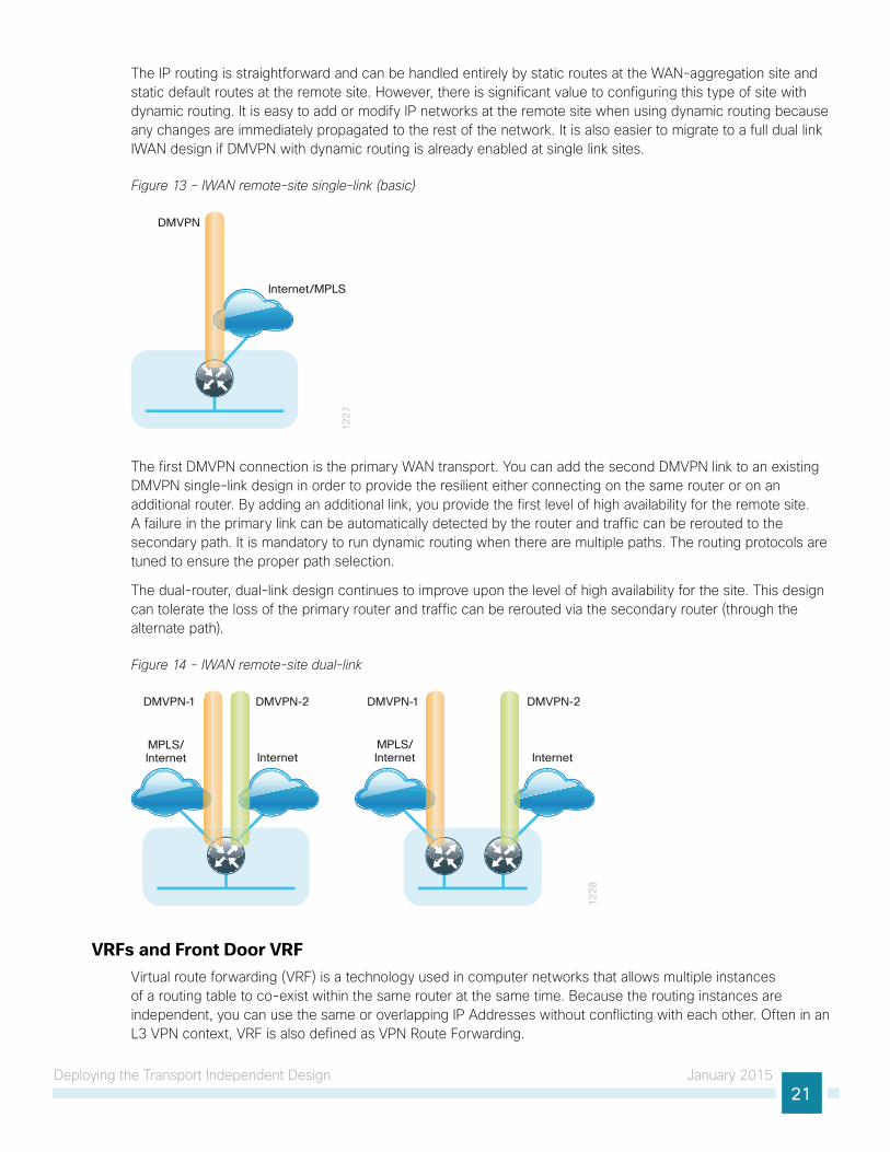
The IP routing is straightforward and can be handled entirely by static routes at the WAN-aggregation site and static default routes at the remote site. However, there is significant value to configuring this type of site with dynamic routing. It is easy to add or modify IP networks at the remote site when using dynamic routing because any changes are immediately propagated to the rest of the network. It is also easier to migrate to a full dual link IWAN design if DMVPN with dynamic routing is already enabled at single link sites.
Figure 13 - IWAN remote-site single-link (basic)
Internet/MPLS
DMVPN
12
27
The first DMVPN connection is the primary WAN transport. You can add the second DMVPN link to an existing DMVPN single-link design in order to provide the resilient either connecting on the same router or on an additional router. By adding an additional link, you provide the first level of high availability for the remote site. A failure in the primary link can be automatically detected by the router and traffic can be rerouted to the secondary path. It is mandatory to run dynamic routing when there are multiple paths. The routing protocols are tuned to ensure the proper path selection.
The dual-router, dual-link design continues to improve upon the level of high availability for the site. This design can tolerate the loss of the primary router and traffic can be rerouted via the secondary router (through the alternate path).
Figure 14 - IWAN remote-site dual-link
InternetMPLS/Internet
DMVPN-1 DMVPN-2 DMVPN-1
Internet
DMVPN-2
12
28
MPLS/Internet
VRFs and Front Door VRFVirtual route forwarding (VRF) is a technology used in computer networks that allows multiple instances of a routing table to co-exist within the same router at the same time. Because the routing instances are independent, you can use the same or overlapping IP Addresses without conflicting with each other. Often in an L3 VPN context, VRF is also defined as VPN Route Forwarding.

Deploying the Transport Independent Design January 201522
IWAN uses VRF to provide the following:
• Default route separation between user traffic and DMVPN tunnel establishment
• Control and data plane separation between inside and outside networks for security purposes
You can implement VRF in a network device by having distinct routing tables, also known as Forwarding Information Bases (FIBs), one per VRF.
The simplest form of VRF implementation is VRF Lite. In this implementation, each router within the network participates in the virtual routing environment on a peer-by-peer basis. VRF Lite configurations are only locally significant.
The IP routing policy used in this design guide for the WAN remote sites does not allow direct Internet access for web browsing or other uses; any remote-site hosts that access the Internet must do so via the Internet edge at the primary site. The end hosts require a default route for all external and Internet destinations; however, this route must force traffic across the primary or secondary WAN transport DMVPN tunnels. DMVPN also has a default route requirement to establish tunnels between sites. The default route for the user traffic over DMVPN conflicts with the default route needed for DMVPN in order to establish tunnels between sites.
The multiple default route conundrum is solved through the use of VRFs on the router. A router can have multiple routing tables that are kept logically separate on the device. This separation is similar to a virtual router from the forwarding plane perspective. The global VRF corresponds to the traditional routing table, and additional VRFs are given names and route descriptors (RDs). Certain features on the router are VRF aware, including static routing and routing protocols, interface forwarding and IPSec tunneling. This set of features is used in conjunction with DMVPN to permit the use of multiple default routes for both the DMVPN hub routers and DMVPN spoke routers. This design uses global VRF for user traffic routing and a VRF for each WAN physical interface for DMVPN tunnel establishment. This combination of features is referred to as FVRF, because the VRF faces the WAN and the router internal LAN and DMVPN tunnel interfaces all remain in the global VRF. For more technical details regarding FVRF, see “Appendix B: Technical Feature Supplement.”
Figure 15 - Front door VRF (FVRF)
12
29
Inside
Outside
InternetEdge
Default
DefaultDefault
VPN-DMZ
Default
Default
Default Route
DMVPNHub Router
WAN Distribution
vrf global vrf IWAN-TRANSPORT
vrf global vrf IWAN-TRANSPORT
Default Route (vrf IWAN-TRANSPORT)
DMVPN Spoke Router
Internet
EIGRP

Deploying the Transport Independent Design January 201523
Design DetailsIn both the IWAN Hybrid and IWAN Dual Internet design models, the DMVPN hub routers must have sufficient IP-routing information in order to provide end-to-end reachability. Maintaining this routing information typically requires a routing protocol, and EIGRP or BGP are recommended for this purpose. However, a single end-to-end process named IWAN-EIGRP is used in this design guide for the WAN. You can also use Internal BGP (IBGP) as an overlay routing protocol and design guidance for IBGP will be added in the future.
At the WAN-aggregation site, you must connect the DMVPN hub routers to the WAN and configure default routing to build the DMVPN tunnels. The MPLS VPN hub uses default routing to the MPLS provider edge (PE) router, and the Internet VPN hubs use default routing to the DMZ-VPN that provides Internet connectivity. The DMVPN hub routers use FVRF and have a static default route with the IWAN-TRANSPORT VRF pointing to their respective next hops.
Figure 16 - IWAN hybrid design model: FVRF default routing
12
31
DistributionLayer
Internet Edge
Internet A Internet B
VPN Hub Router
vrf IWAN-TRANSPORT-2vrf IWAN-TRANSPORT-1
Default
Default
MPLS CE Router
Default Route (vrf IWAN-TRANSPORT-1)
Default Route (vrf IWAN-TRANSPORT-2)
Figure 17 - IWAN dual Internet design model: FVRF default routing
12
32
DistributionLayer
Internet Edge
Internet A Internet B
VPN HubRouters
vrf IWAN-TRANSPORT-4vrf IWAN-TRANSPORT-3
Default
Default Route (vrf IWAN-TRANSPORT-3)
Default Route (vrf IWAN-TRANSPORT-4)
Default

Deploying the Transport Independent Design January 201524
EIGRPCisco uses EIGRP as the primary routing protocol because it is easy to configure, does not require a large amount of planning, has flexible summarization and filtering, and can scale to large networks. As networks grow, the number of IP prefixes or routes in the routing tables grows as well. You should program IP summarization on links where logical boundaries exist, like distribution layer links to the wide area or to a core. By performing IP summarization, you can reduce the amount of bandwidth, processor, and memory necessary to carry large route tables, as well as reduce convergence time associated with a link failure.
With the advances in EIGRP, this guide uses EIGRP named mode. The use of named mode EIGRP allows related EIGRP configurations to be centrally located in the configuration. Named mode EIGRP includes features such as wide metrics, supporting larger multi-gigabit links. For added security, EIGRP neighbor authentication has been implemented to prevent unauthorized neighbor associations.
With EIGRP named mode configuration, EIGRP Wide Metric support is on by default and backward compatible with existing routes.
Tech Tip
In this design, the primary EIGRP process (AS 400) is referred to as IWAN-EIGRP and uses EIGRP named configuration.
The IWAN-EIGRP process is configured in the WAN-aggregation site in order to connect to the primary site LAN distribution layer, across the DMVPN tunnels and at all WAN remote sites, including those with distribution-layer LAN topologies.
EncryptionThe primary goal of encryption is to provide data confidentiality, integrity, and authenticity by encrypting IP packets as the data travels across a network.
The encrypted payloads are then encapsulated with a new header (or multiple headers) and transmitted across the network. The additional headers introduce a certain amount of overhead to the overall packet length. The following table highlights the packet overhead associated with encryption based on the additional headers required for various combinations of IPsec and GRE.
Table 7 - Overhead associated with IPsec and GRE
Encapsulation Overhead
GRE only 24 bytes
IPsec (Transport Mode) 36 bytes
IPsec (Tunnel Mode) 52 bytes
IPsec (Transport Mode) + GRE 60 bytes
IPsec (Tunnel Mode) + GRE 76 bytes
There is a maximum transmission unit (MTU) parameter for every link in an IP network and typically the MTU is 1500 bytes. IP packets larger than 1500 bytes must be fragmented when transmitted across these links. Fragmentation is not desirable and can impact network performance. To avoid fragmentation, the original packet size plus overhead must be 1500 bytes or less, which means that the sender must reduce the original packet size. To account for other potential overhead, Cisco recommends that you configure tunnel interfaces with a 1400 byte MTU.

Deploying the Transport Independent Design January 201525
There are dynamic methods for network clients to discover the path MTU, which allow the clients to reduce the size of packets they transmit. However, in many cases, these dynamic methods are unsuccessful, typically because security devices filter the necessary discovery traffic. This failure to discover the path MTU drives the need for a method that can reliably inform network clients of the appropriate packet size. The solution is to implement the ip tcp adjust mss [size] command on the WAN routers, which influences the TCP maximum segment size (MSS) value reported by end hosts.
The MSS defines the maximum amount of data that a host is willing to accept in a single TCP/IP datagram. The MSS value is sent as a TCP header option only in TCP SYN segments. Each side of a TCP connection reports its MSS value to the other side. The sending host is required to limit the size of data in a single TCP segment to a value less than or equal to the MSS reported by the receiving host.
The IP and TCP headers combine for 40 bytes of overhead, so the typical MSS value reported by network clients will be 1460. This design includes encrypted tunnels with a 1400 byte MTU, so the MSS used by endpoints should be configured to be 1360 to minimize any impact of fragmentation. In this solution, you implement the ip tcp adjust mss 1360 command on all WAN facing router interfaces.
IPsec security association (SA) anti-replay is a security service in which the decrypting router can reject duplicate packets and protect itself against replay attacks. Cisco QoS gives priority to high-priority packets. This prioritization may cause some low-priority packets to be discarded. Cisco IOS provides anti-replay protection against an attacker duplicating encrypted packets. By expanding the IPsec anti-replay window you can allow the router to keep track of more than the default of 64 packets. In this solution you implement the crypto ipsec security-association replay window-size command in order to increase the window size on all DMVPN routers.
IPsec uses a key exchange between the routers in order to encrypt/decrypt the traffic. You can exchange these keys by using a simple pre-sharing algorithm or a certificate authority. You can deploy IOS-CA in order to enroll, store, authenticate and distribute the keys to routers that request them. If a certificate authority is chosen, the certificates and keys can be distributed using the simple certificate enrollment protocol (SCEP) for automated certificate retrieval by the routers.
DMVPNTo address data security and privacy concerns, all IWAN traffic will be encrypted over DMVPN.
All use cases in the Cisco IWAN design are dual-link. The dual-link use cases require a DMVPN dual-cloud design, each with a single hub router. Multiple DMVPN hub routers are supported, but the current version of PfR supports only a single hub router per link. The DMVPN routers use tunnel interfaces that support IP unicast as well as IP multicast and broadcast traffic, including the use of dynamic routing protocols. After the initial spoke-to-hub tunnel is active, it is possible to create dynamic spoke-to-spoke tunnels when site-to-site IP traffic flows require it.
The information required by a spoke to set up dynamic spoke-to-spoke tunnels and properly resolve other spokes is provided through the next-hop resolution protocol (NHRP) within DMVPN. Spoke-to-spoke tunnels allow for the optimal routing of traffic between locations without indirect forwarding through the hub. Idle spoke-to-spoke tunnels gracefully time out after a period of inactivity.
It is common for a firewall to be placed between the DMVPN hub routers and the Internet. In many cases, the firewall may provide NAT from an internal RFC-1918 IP address (such as 192.168.146.10) to an Internet-routable IP address. The DMVPN solution works well with NAT but requires the use of IPsec transport mode to support a DMVPN hub behind static NAT.
The IWAN DMVPN design requires the use of Internet Key Management Protocol version 2 (IKEv2) keepalive intervals for dead peer detection (DPD), which is essential to facilitate fast reconvergence and for spoke registration to function properly in case a DMVPN hub is restarted. This design enables a spoke to detect that an encryption peer has failed and that the IKEv2 session with that peer is stale, which then allows a new one to be created.

Deploying the Transport Independent Design January 201526
Without DPD, the IPsec security association (SA) must time out (the default is 60 minutes) and when the router cannot renegotiate a new SA, a new IKEv2 session is initiated. The IWAN design with the recommended IKEv2 and DPD timers reduces this convergence time to 40 seconds.
Figure 18 - DMVPN dual-cloud
21
58DMVPN Spoke
DMVPN Spoke DMVPN Spoke
DMVPN Spoke
DMVPN Head End
Cloud 1Hub
Cloud 2Hub
DMVPN Head End
DMVPN Spoke
DMVPN Cloud 1 DMVPN Cloud 2
Internet
Spoke-Spoke Tunnel
One of the key benefits of the DMVPN solution is that the spoke routers can use dynamically assigned addresses, often using DHCP from an Internet provider. The spoke routers can leverage an Internet default route for reachability to the hub routers and also other spoke addresses.
The DMVPN hub routers have static IP addresses assigned to their public-facing interfaces. This configuration is essential for proper operation as each of the spoke routers have these IP addresses embedded in their configurations.

Deploying the Transport Independent Design January 201527
Deployment Details
This guide uses the following conventions for commands that you enter at the command-line interface (CLI).
Commands to enter at a CLI prompt: configure terminal
Commands that specify a value for a variable: ntp server 10.10.48.17
Commands with variables that you must de�ne: class-map [highest class name]
Commands at a CLI or script prompt: Router# enable
Long commands that line wrap are underlined. Enter them as one command:
police rate 10000 pps burst 10000 packets conform-action
Noteworthy parts of system output (or of device con�guration �les) are highlighted: interface Vlan64 ip address 10.5.204.5 255.255.255.0
How to Read Commands
The procedures in this section provide examples for most settings. The actual settings and values that you use are determined by your current network configuration.The following optional process is used for both the IWAN hybrid design model and the IWAN dual Internet design model.
Configuring an IOS Certificate Authority
1. Configure the IOS CA platform
2. Configure the WAN-facing VRFs
3. Configure connectivity to the three networks
4. Configure certificate authority
PR
OC
ESS
Use this optional process if you want to deploy an IOS Certificate Authority (IOS CA) on a router in your DMZ with access from the internal network and the MPLS provider network. Skip this process if you are using pre-shared keys or if you plan to use a different certificate authority. You can create a more complex CA environment, but the same basic reachability principles will apply for an IWAN enabled solution.
For this process, you configure an IOS CA with three interfaces:
• The first interface on the internal LAN allows access from the hub routers and is also used for managing the router.
• The second interface on the DMZ allows access from remote site routers with Internet connectivity.
• The third interface on the MPLS provider network allows access from remote site routers with MPLS connectivity.

Deploying the Transport Independent Design January 201528
Each interface is in its own VRF and there is no routing between the interfaces. Three static routes allow the IOS CA to reach each network individually.
Figure 19 - IOS CA with three non-routed interfaces
WAN DistributionLayer
Core Layer
DMVPN 2
12
33
MPLS
DMVPN 1
Internet EdgeDMVPN Hub
Router (MPLS)DMVPN HubRouter (INET)
INET
IOS-CA #1
#2#3
Procedure 1 Configure the IOS CA platform
Step 1: Configure the device host name. Make it easy to identify the device.
hostname IWAN-IOS-CA
Step 2: Configure the local login and password.
The local login account and password provides basic access authentication to a router that provides only limited operational privileges. The enable password secures access to the device configuration mode. By enabling password encryption, you prevent the disclosure of plain text passwords when viewing configuration files.
username admin secret c1sco123enable secret c1sco123service password-encryption
aaa new-model
By default, https access to the router uses the enable password for authentication.
Step 3: (Optional) Configure centralized user authentication.
As networks scale in the number of devices to maintain, it poses an operational burden to maintain local user accounts on every device. A centralized authentication, authorization and accounting (AAA) service reduces operational tasks per device and provides an audit log of user access for security compliance and root cause analysis. When AAA is enabled for access control, AAA controls all management access to the network infrastructure devices (secure shell [SSH] and hypertext transfer protocol secure [HTTPS]).

Deploying the Transport Independent Design January 201529
Terminal access controller access control system plus (TACACS+) is the primary protocol used to authenticate management logins on the infrastructure devices to the AAA server. A local AAA user database is also defined (in Step 2) on each network infrastructure device in order to provide a fallback authentication source in case the centralized TACACS+ server is unavailable.
tacacs server TACACS-SERVER-1 address ipv4 10.4.48.15 key SecretKey
aaa group server tacacs+ TACACS-SERVERS server name TACACS-SERVER-1
aaa authentication login default group TACACS-SERVERS localaaa authorization exec default group TACACS-SERVERS localaaa authorization console
ip http authentication aaa
Step 4: Configure device management protocols.
HTTPS and SSH are secure replacements for the HTTP and Telnet protocols. They use secure sockets layer (SSL) and TLS in order to provide device authentication and data encryption.
Secure management of the network device is enabled through the use of the SSH and HTTPS protocols. Both protocols are encrypted for privacy and Telnet is turned off. SCP is enabled, which allows the use of code upgrades using Prime Infrastructure via SSH based SCP protocol. HTTP is needed for SCEP and CRL download.
Specify the transport preferred none on vty lines to prevent errant connection attempts from the CLI prompt. Without this command, if the ip name-server is unreachable, long timeout delays may occur for mistyped commands.
ip domain-name cisco.localip ssh version 2
ip http server
ip http secure-server
ip scp server enable
line vty 0 15
transport input ssh
transport preferred none
When synchronous logging of unsolicited messages and debug output is turned on, console log messages are displayed on the console after interactive CLI output is displayed or printed. With this command, you can continue typing at the device console when debugging is enabled.
line con 0
transport preferred none
logging synchronous
Enable SNMP in order to allow the network infrastructure devices to be managed by a NMS. SNMPv2c is configured both for a read-only and a read-write community string.
snmp-server community cisco RO snmp-server community cisco123 RWsnmp-server ifindex persist ! IOS Classic Only
snmp ifmib ifindex persist ! IOS XE Only

Deploying the Transport Independent Design January 201530
Step 5: (Optional) In networks where network operational support is centralized, you can increase network security by using an access list to limit the networks that can access your device. In this example, only devices on the 10.4.48.0/24 network will be able to access the device via SSH or SNMP.
access-list 55 permit 10.4.48.0 0.0.0.255line vty 0 15
access-class 55 in
snmp-server community cisco RO 55 snmp-server community cisco123 RW 55snmp-server ifindex persist ! IOS Classic Only
snmp ifmib ifindex persist ! IOS XE Only
If you configure an access-list on the vty interface you may lose the ability to use ssh to login from one router to the next for hop-by-hop troubleshooting.
Tech Tip
Step 6: Configure a synchronized clock.
The network time protocol (NTP) is designed to synchronize a network of devices. An NTP network usually gets its time from an authoritative time source, such as a radio clock or an atomic clock attached to a time server. NTP then distributes this time across the organizations network.
A synchronized clock is an absolute requirement for routers using certificates, since certificates have a valid lifetime. The local NTP server typically references a more accurate clock feed from an outside source. By configuring console messages, logs, and debug output to provide time stamps on output, you can cross-reference events in a network.
ntp server 10.4.48.17
clock timezone PST -8 clock summer-time PDT recurring
service timestamps debug datetime msec localtime
service timestamps log datetime msec localtime
Procedure 2 Configure the WAN-facing VRFs
The VRF name is arbitrary, but it is useful to select a name that describes the VRF. The VRF must be enabled for IPv4.
This design uses VRF Lite, so the selection is only locally significant to the device. It is a best practice to use the same VRF/RD combination across multiple devices when using VRFs in a similar manner. However, this convention is not strictly required.
Step 1: Configure the public Internet and MPLS provider VRFs.

Deploying the Transport Independent Design January 201531
Example: DMZ facing VRF (public Internet)vrf definition IWAN-PUBLIC description IWAN PUBLIC (Internet DMZ) address-family ipv4
Example: MPLS facing VRF (MPLS provider)vrf definition IWAN-TRANSPORT-1 description IWAN TRANSPORT 1 (MPLS) address-family ipv4
Procedure 3 Configure connectivity to the three networks
Each interface is in its own VRF and there is no routing between the interfaces. Three static routes allow the IOS CA to reach each network individually.
Table 8 - IOS CA IP address assignments
Network IP Address NAT IP Address
Internal 10.6.24.11 N/A
Internet DMZ 192.168.144.127 172.16.140.110 (ISP-A)
MPLS Provider 192.168.6.254 N/A
The NAT IP address is added in the “Configuring the Firewall and DMZ Switch” process later in this guide.
Step 1: The internal address is an inside address that can be accessed from the hub site or a remote site if the site is already up and running with a DMVPN tunnel.
interface GigabitEthernet0/0 description Internal ip address 10.6.24.11 255.255.255.224 no shutdown
Step 2: The second interface is connected to the DMZ network. This address is only reachable from the IWAN-PUBLIC VFR and has NAT applied in order to be addressable via the Internet.
interface GigabitEthernet0/1 description Internet DMZ vrf forwarding IWAN-PUBLIC ip address 192.168.144.127 255.255.255.0 no shutdown
Step 3: The third interface is connected to the MPLS provider network. This address is reachable from the IWAN-TRANPORT-1 VRF at a remote site before there is a DMVPN tunnel.
interface GigabitEthernet0/2 description MPLS Provider vrf forwarding IWAN-TRANSPORT-1 ip address 192.168.6.254 255.255.255.252 no shutdown

Deploying the Transport Independent Design January 201532
Step 4: Configure IP routing using static routes.
Three static routes are configured. The first default static route is for traffic into the internal LAN. The second default static route is for the VRF IWAN-PUBLIC towards the Internet and the third default static route is for VRF IWAN-TRANSPORT-1 towards the MPLS provider.
ip route 0.0.0.0 0.0.0.0 10.6.24.1ip route vrf IWAN-PUBLIC 0.0.0.0 0.0.0.0 192.168.144.1ip route vrf IWAN-TRANSPORT-1 0.0.0.0 0.0.0.0 192.168.6.253
Procedure 4 Configure certificate authority
The following commands configure the certificate authority (CA) on the router. This CA can be part of a public key infrastructure (PKI) hierarchy, but only of IOS authorities, and the certificate from the root CA must be issued via SCEP.
Step 1: Configure the server.
crypto pki server IWAN-IOS-CA database level complete
no database archive
issuer-name CN=IWAN-IOS-CA.cisco.local L=SanJose St=CA C=US
Step 2: Configure the server to use SCEP for issuing certificates.
grant auto
Step 3: Configure the lifetime for the issued certificates at 2 years. The time is in days.
lifetime certificate 730
Step 4: Configure the lifetime for the certificate server signing certificate at 3 years. The time is in days.
lifetime ca-certificate 1095
Step 5: Configure the location for certificate revocation lists.
In order to force the parser to retain the embedded question mark within the specified location, enter CTRL+V prior to the question mark. If this action is not taken, CRL retrieval through HTTP returns an error message.
Tech Tip
cdp-url http://10.6.24.11/cgi-bin/pkiclient.exe?operation=GetCRL database url crl nvram:

Deploying the Transport Independent Design January 201533
Step 6: Start the server with the no shutdown command.
crypto pki server IWAN-IOS-CA no shutdown
%Some server settings cannot be changed after CA certificate generation.
% Please enter a passphrase to protect the private key
% or type Return to exit
Password: c1sco123
Re-enter password: c1sco123% Generating 1024 bit RSA keys, keys will be non-exportable...
[OK] (elapsed time was 2 seconds)
% Certificate Server enabled.
IWAN-IOS-CA(cs-server)#
Dec 15 13:19:49.254: %PKI-6-CS_ENABLED: Certificate server now enabled.
The following trustpoint and rsa keypair are automatically generated when you start the server:
crypto pki trustpoint IWAN-IOS-CA revocation-check crl
rsakeypair IWAN-IOS-CA
For more information, including options for configuring certificates, see the following document:
http://www.cisco.com/c/en/us/td/docs/ios-xml/ios/sec_conn_pki/configuration/15-mt/sec-pki-15-mt-book.pdf
Tech Tip

Deploying the Transport Independent Design January 201534
Configuring DMVPN Hub Router
1. Configure the distribution switch
2. Configure the WAN aggregation platform
3. Configure connectivity to the LAN
4. Configure the WAN-facing VRF
5. Connect to the MPLS WAN or Internet
6. Configure IKEv2 and IPsec
7. Configure the mGRE tunnel
8. Configure EIGRP
PR
OC
ESS
Use this process for the both the IWAN hybrid design model and the IWAN dual Internet design model, and repeat it for each DMVPN hub router.
Table 9 - DMVPN Hub Router IP Addresses
DMVPN Cloud HostnameLoopback IP Address
Port Channel IP Address
Hybrid—Primary WAN VPN-MPLS-ASR1002X-1 10.6.32.241/32 10.6.32.2/30
Hybrid—Secondary WAN VPN-INET-4451X-2 10.6.32.242/32 10.6.32.6/30
Dual Internet—Primary WAN VPN-INET-ASR1002X-3 10.6.32.243/32 10.6.32.18/30
Dual Internet—Secondary WAN VPN-INET-ASR1002X-4 10.6.32.244/32 10.6.32.22/30
Procedure 1 Configure the distribution switch
This process assumes that the distribution switch has already been configured following the guidance in the Campus Wired LAN Technology Design Guide. Only the procedures required to support the integration of the WAN aggregation router into the deployment are included.
Reader Tip
The LAN distribution switch is the path to the organization’s main campus and data center. A Layer 3 port-channel interface connects to the distribution switch to the WAN aggregation router and the internal routing protocol peers across this interface.
As a best practice, use the same channel numbering on both sides of the link where possible.
Tech Tip

Deploying the Transport Independent Design January 201535
Step 1: Configure the Layer 3 port-channel interface and assign the IP address.
interface Port-channel1 description VPN-MPLS-ASR1002X-1 no switchport
ip address 10.6.32.1 255.255.255.252 ip pim sparse-mode
load-interval 30
no shutdown
Step 2: Configure EtherChannel member interfaces.
Configure the physical interfaces to tie to the logical port-channel using the channel-group command. The number for the port-channel and channel-group must match. Not all router platforms can support LACP to negotiate with the switch, so to keep the design consistent across the network, EtherChannel is configured statically, which also reduces startup times.
Also, apply the egress QoS macro that was defined in the platform configuration procedure in order to ensure traffic is prioritized appropriately.
interface GigabitEthernet1/0/1 description VPN-MPLS-ASR1002X-1 Gig0/0/0
interface GigabitEthernet2/0/1 description VPN-MPLS-ASR1002X-1 Gig0/0/1
interface range GigabitEthernet1/0/1, GigabitEthernet2/0/1 no switchport
channel-group 1 mode on logging event link-status
logging event trunk-status
logging event bundle-status
load-interval 30
no shutdown
macro apply EgressQoS
Step 3: Allow the routing protocol to form neighbor relationships across the port channel interface.
router eigrp IWAN-EIGRP address-family ipv4 unicast autonomous-system 400 af-interface Port-channel1 no passive-interface
authentication mode md5
authentication key-chain LAN-KEY exit-af-interface
exit-address-family

Deploying the Transport Independent Design January 201536
Step 4: If you had previously configured EIGRP stub routing on your WAN distribution switch, disable the feature.
router eigrp IWAN-EIGRP address-family ipv4 unicast autonomous-system 400 no eigrp stub
exit-address-family
Step 5: On the distribution layer switch, configure the Layer 3 interface connected to the LAN core to summarize the WAN network ranges.
It is a best practice to summarize IP routes from the WAN distribution layer towards the core.
Tech Tip
router eigrp IWAN-EIGRP address-family ipv4 unicast autonomous-system 400 af-interface Port-channel38 summary-address 10.6.32.0 255.255.248.0 summary-address 10.7.0.0 255.255.0.0 summary-address 10.255.240.0 255.255.248.0 exit-af-interface
exit-address-family
Procedure 2 Configure the WAN aggregation platform
Within this design, there are features and services that are common across all WAN aggregation routers. These are system settings that simplify and secure the management of the solution.
Step 1: Configure the device host name. Make it easy to identify the device.
hostname VPN-MPLS-ASR1002X-1
Step 2: Configure local login and password.
The local login account and password provide basic access authentication to a router, which provides only limited operational privileges. The enable password secures access to the device configuration mode. By enabling password encryption, you prevent the disclosure of plain text passwords when viewing configuration files.
username admin secret c1sco123enable secret c1sco123service password-encryption
aaa new-model
By default, https access to the router will use the enable password for authentication.
Step 3: (Optional) Configure centralized user authentication.
As networks scale in the number of devices to maintain, it poses an operational burden to maintain local user accounts on every device. A centralized AAA service reduces operational tasks per device and provides an audit log of user access for security compliance and root cause analysis. When AAA is enabled for access control, AAA controls all management access to the network infrastructure devices (SSH and HTTPS).

Deploying the Transport Independent Design January 201537
TACACS+ is the primary protocol used to authenticate management logins on the infrastructure devices to the AAA server. A local AAA user database is also defined (in Step 2) on each network infrastructure device in order to provide a fallback authentication source in case the centralized TACACS+ server is unavailable.
tacacs server TACACS-SERVER-1 address ipv4 10.4.48.15 key SecretKey
aaa group server tacacs+ TACACS-SERVERS server name TACACS-SERVER-1
aaa authentication login default group TACACS-SERVERS localaaa authorization exec default group TACACS-SERVERS localaaa authorization console
ip http authentication aaa
Step 4: Configure device management protocols.
Secure HTTPS and SSH are secure replacements for the HTTP and Telnet protocols. They use SSL and TLS in order to provide device authentication and data encryption.
Secure management of the network device is enabled through the use of the SSH and HTTPS protocols. Both protocols are encrypted for privacy and the nonsecure protocols, Telnet and HTTP, are turned off. SCP is enabled, which allows the use of code upgrades using Prime Infrastructure via SSH-based SCP protocol.
Specify the transport preferred none on vty lines in order to prevent errant connection attempts from the command line interface (CLI) prompt. Without this command, if the ip name-server is unreachable, long timeout delays may occur for mistyped commands.
ip domain-name cisco.localip ssh version 2
no ip http server
ip http secure-server
ip scp server enable
line vty 0 15
transport input ssh
transport preferred none
When synchronous logging of unsolicited messages and debug output is turned on, console log messages are displayed on the console after interactive CLI output is displayed or printed. With this command, you can continue typing at the device console when debugging is enabled.
line con 0
transport preferred none
logging synchronous
Enable SNMP in order to allow the network infrastructure devices to be managed by a Network Management System (NMS). SNMPv2c is configured both for a read-only and a read-write community string.
snmp-server community cisco RO snmp-server community cisco123 RWsnmp-server ifindex persist ! IOS Classic Only
snmp ifmib ifindex persist ! IOS XE Only

Deploying the Transport Independent Design January 201538
Step 5: (Optional) In networks where network operational support is centralized, you can increase network security by using an access list to limit the networks that can access your device. In this example, only devices on the 10.4.48.0/24 network will be able to access the device via SSH or SNMP.
access-list 55 permit 10.4.48.0 0.0.0.255line vty 0 15
access-class 55 in
snmp-server community cisco RO 55 snmp-server community cisco123 RW 55snmp-server ifindex persist ! IOS Classic Only
snmp ifmib ifindex persist ! IOS XE Only
If you configure an access-list on the vty interface you may lose the ability to use ssh to login from one router to the next for hop-by-hop troubleshooting.
Tech Tip
Step 6: Configure a synchronized clock.
NTP is designed to synchronize a network of devices. An NTP network usually gets its time from an authoritative time source, such as a radio clock or an atomic clock attached to a time server. NTP then distributes this time across the organizations network.
You should program network devices to synchronize to a local NTP server in the network. The local NTP server typically references a more accurate clock feed from an outside source. By configuring console messages, logs, and debug output to provide time stamps on output, you can cross-reference events in a network.
ntp server 10.4.48.17
clock timezone PST -8 clock summer-time PDT recurring
service timestamps debug datetime msec localtime
service timestamps log datetime msec localtime
Step 7: Configure an in-band management interface.
The loopback interface is a logical interface that is always reachable as long as the device is powered on and any IP interface is reachable to the network. Because of this capability, the loopback address is the best way to manage the router in-band. Layer 3 process and features are also bound to the loopback interface to ensure process resiliency.
The loopback address is commonly a host address with a 32-bit address mask. Allocate the loopback address from the IP address block that the router summarizes to the rest of the network.
interface Loopback 0
ip address 10.6.32.241 255.255.255.255 ip pim sparse-mode
The ip pim sparse-mode command will be explained further in the process.

Deploying the Transport Independent Design January 201539
Bind the device processes for SNMP, SSH, PIM, TACACS+ and NTP to the loopback interface address for optimal resiliency:
snmp-server trap-source Loopback0
ip ssh source-interface Loopback0
ip pim register-source Loopback0
ip tacacs source-interface Loopback0
ntp source Loopback0
Step 8: Configure IP unicast routing authentication key.
key chain LAN-KEY key 1 key-string c1sco123
Step 9: Configure IP unicast routing using EIGRP named mode.
EIGRP is configured facing the LAN distribution or core layer. In this design, the port-channel interface and the loopback must be EIGRP interfaces. The loopback may remain a passive interface. Passive interfaces are used to prevent accidental peering and to reduce the EIGRP traffic on a network segment. The network range must include both interface IP addresses, either in a single network statement or in multiple network statements. This design uses a best practice of assigning the router ID to a loopback address.
router eigrp IWAN-EIGRP address-family ipv4 unicast autonomous-system 400 af-interface default
passive-interface
exit-af-interface
network 10.6.0.0 0.1.255.255 eigrp router-id 10.6.32.241 nsf
exit-address-family
Step 10: Configure IP Multicast routing.
In this design, which is based on sparse mode multicast operation, Auto RP is used to provide a simple yet scalable way to provide a highly resilient RP environment.
Step 11: Enable IP Multicast routing on the platforms in the global configuration mode.
ip multicast-routing
Step 12: The Cisco ASR1000 series and ISR4000 series routers require the distributed keyword.
ip multicast-routing distributed
Step 13: Configure every Layer 3 switch and router to discover the IP Multicast RP with autorp. Use the ip pim autorp listener command to allow for discovery across sparse mode links. This configuration provides for future scaling and control of the IP Multicast environment and can change based on network needs and design.
ip pim autorp listener
Step 14: Enable sparse mode multicast operation.
ip pim sparse-mode

Deploying the Transport Independent Design January 201540
Procedure 3 Configure connectivity to the LAN
Any links to adjacent distribution layers should be Layer 3 links or Layer 3 EtherChannels.
Step 1: Enable QoS support for port-channel interfaces.
platform qos port-channel-aggregate 1
This only applies to ASR1000 routers. If there is a requirement to configure QoS on the port-channel interface, make sure to enable platform support before you create the port-channel interface on the router.
platform qos port-channel-aggregate [port-channel number]
If you apply this command globally for an existing port-channel-interface that already has been configured, you will receive an error:
"Port-channel 1 has been configured with non-aggregate
mode already, please use different interface number that
port-channel interface hasn’t been configured"
If you need to apply a QoS policy to an existing port-channel interface, you must first delete the existing port-channel interface and configure platform support for that port-channel interface number.
Tech Tip
Step 2: Configure Layer 3 port-channel interface.
interface Port-channel1 ip address 10.6.32.2 255.255.255.252 ip pim sparse-mode
no shutdown
Step 3: Configure EtherChannel member interfaces.
Configure the physical interfaces to tie to the logical port-channel using the channel-group command. The number for the port-channel and channel-group must match.
interface GigabitEthernet0/0/0 description IW-WAN-D3750X Gig1/0/1 interface GigabitEthernet0/0/1 description IW-WAN-D3750X Gig2/0/1
interface range GigabitEthernet0/0/0, GigabitEthernet0/0/1 no ip address
channel-group 1 cdp enable
no shutdown

Deploying the Transport Independent Design January 201541
Step 4: Configure the EIGRP interface.
Allow EIGRP to form neighbor relationships across the interface to establish peering adjacencies and exchange route tables. In this step, you configure EIGRP authentication by using the authentication key specified in the previous procedure.
router eigrp IWAN-EIGRP address-family ipv4 unicast autonomous-system 400 af-interface Port-channel1 no passive-interface
authentication mode md5
authentication key-chain LAN-KEY exit-af-interface
exit-address-family
Procedure 4 Configure the WAN-facing VRF
Next, you create a WAN-facing VRF in order to support FVRF for DMVPN. The VRF name is arbitrary but it is useful to select a name that describes the VRF. The VRF must be enabled for IPv4.
Table 10 - VRF assignments
IWAN Design Primary WAN VRF Secondary WAN VRF
Hybrid IWAN-TRANSPORT-1 IWAN-TRANSPORT-2
Dual Internet IWAN-TRANSPORT-3 IWAN-TRANSPORT-4
This design uses VRF Lite, so the selection is only locally significant to the device. It is a best practice to use the same VRF/RD combination across multiple devices when using VRFs in a similar manner. However, this convention is not strictly required.
Step 1: Configure the primary WAN VRF.
Example: Transport 1 in IWAN hybrid design modelvrf definition IWAN-TRANSPORT-1 address-family ipv4
Procedure 5 Connect to the MPLS WAN or Internet
Each IWAN DMVPN hub requires a connection to the WAN transport, which is either MPLS or Internet.
If you are using MPLS in this design, the DMVPN hub is connected to the service provider’s MPLS PE router. The IP addressing used between IWAN CE and MPLS PE routers must be negotiated with your MPLS carrier.
If you are using the Internet in this design, the DMVPN hub is connected through a Cisco ASA 5500 Adaptive Security Appliance (ASA) using a DMZ interface specifically created and configured for a VPN termination router.

Deploying the Transport Independent Design January 201542
The IP address that you use for the Internet-facing interface of the DMVPN hub router must be an Internet-routable address. There are two possible methods for accomplishing this task:
• Assign a routable IP address directly to the router.
• Assign a non-routable RFC-1918 address directly to the router and use a static NAT on the Cisco ASA 5500 to translate the router IP address to a routable IP address.
This design assumes that the Cisco ASA 5500 is configured for static NAT for the DMVPN hub router.
Option 1: MPLS WAN physical WAN interfaceThe DMVPN design is using FVRF, so you must place the WAN interface into the VRF configured in the previous procedure.
Step 1: Enable the interface, select the VRF, and assign the IP address.
interface GigabitEthernet0/0/3 vrf forwarding IWAN-TRANSPORT-1 ip address 192.168.6.1 255.255.255.252 no shutdown
Step 2: If you are deploying an IOS CA for MPLS remote site routers, extend the MPLS provider network using a second physical interface.
The interface will have an IP address with a 30-bit mask on the same subnet as the IOS CA in the IWAN-TRANSPORT-1 VRF.
interface GigabitEthernet0/0/5 description IWAN-IOS-CA vrf forwarding IWAN-TRANSPORT-1 ip address 192.168.6.253 255.255.255.252 no shutdown
Step 3: Configure the VRF-specific default routing.
The VRF created for FVRF must have its own default route to the MPLS. This default route points to the MPLS PE router’s IP address and is used by DMVPN for tunnel establishment.
ip route vrf IWAN-TRANSPORT-1 0.0.0.0 0.0.0.0 192.168.6.2
Option 2: Internet WAN physical WAN interfaceThe DMVPN design is using FVRF, so you must place the WAN interface into the VRF configured in Procedure 4, “Configure the WAN-facing VRF.”
Step 1: Enable the interface, select the VRF, and assign the IP address.
interface GigabitEthernet0/0/3 vrf forwarding IWAN-TRANSPORT-2 ip address 192.168.146.10 255.255.255.0 no shutdown

Deploying the Transport Independent Design January 201543
Step 2: Configure the VRF-specific default routing.
The VRF created for FVRF must have its own default route to the Internet. This default route points to the Cisco ASA 5500’s DMZ interface IP address.
ip route vrf IWAN-TRANSPORT-2 0.0.0.0 0.0.0.0 192.168.146.1
Figure 20 - Physical and logical views for DMZ connection
12
34
DistributionSwitch
DMVPN HubRouter
gig 0/0/3 gig 0/0/4
DMZSwitch
DistributionSwitch
DMVPN HubRouter
vrf IWAN-TRANSPORT-2 (.10)
192.168.146.0/24
VLAN: 1118 (.1)dmz-vpn
Physical Logical
Procedure 6 Configure IKEv2 and IPsec
The parameters in the tables below are used in this procedure. Use the values in the table that represents the design model that you are configuring.
Table 11 - Crypto parameters: IWAN hybrid design model
Parameter Primary WAN Secondary WAN
vrf IWAN-TRANSPORT-1 IWAN-TRANSPORT-2
crypto ikev2 keyring DMVPN-KEYRING-1 DMVPN-KEYRING-2
crypto ikev2 profile FVRF-IKEv2-IWAN-TRANSPORT-1 FVRF-IKEv2-IWAN-TRANSPORT-2
crypto ipsec profile DMVPN-PROFILE-TRANSPORT-1 DMVPN-PROFILE-TRANSPORT-2
Table 12 - Crypto Parameters: IWAN dual Internet design model
Parameter Primary WAN Secondary WAN
vrf IWAN-TRANSPORT-3 IWAN-TRANSPORT-4
crypto ikev2 keyring DMVPN-KEYRING-3 DMVPN-KEYRING-4
crypto ikev2 profile FVRF-IKEv2-IWAN-TRANSPORT-3 FVRF-IKEv2-IWAN-TRANSPORT-4
crypto ipsec profile DMVPN-PROFILE-TRANSPORT-3 DMVPN-PROFILE-TRANSPORT-4
IPsec uses a key exchange between the routers in order to encrypt/decrypt the traffic. These keys can be exchanged using a simple pre-sharing algorithm or a certificate authority. It is also possible to use a combination of the two, which is useful during a migration from one method to the other.

Deploying the Transport Independent Design January 201544
You have two options for configuring key exchange: using pre-shared keys or using a certificate authority.
Option 1: Configure with pre-shared keys
Step 1: Configure the crypto keyring for pre-shared keys.
The crypto keyring defines a pre-shared key (or password) valid for IP sources that are reachable within a particular VRF. This key is a wildcard pre-shared key if it applies to any IP source. A wildcard key is configured using the 0.0.0.0 0.0.0.0 as the network/mask combination.
crypto ikev2 keyring [keyring name] peer ANY address 0.0.0.0 0.0.0.0 pre-shared-key [password]
Example: Primary WAN hub router in the IWAN hybrid design modelcrypto ikev2 keyring DMVPN-KEYRING-1 peer ANY address 0.0.0.0 0.0.0.0 pre-shared-key c1sco123
Step 2: Configure the IKEv2 profile.
The default IKEv2 proposal is used, which includes the following:
• Encryption with Advanced Encryption Standard (AES) cipher with a 256-bit key
• Integrity with Secure Hash Standard (SHA) with 512-bit digest
• Pseudo-random function with SHA with 512-bit digest
• Diffie-Hellman group: 5
VPN-MPLS-ASR1002X-1# show crypto ikev2 proposalIKEv2 proposal: default
Encryption: AES-CBC-256 AES-CBC-192 AES-CBC-128
Integrity : SHA512 SHA384 SHA256 SHA96 MD596
PRF : SHA512 SHA384 SHA256 SHA1 MD5
DH Group : DH_GROUP_1536_MODP/Group 5 DH_GROUP_1024_MODP/Group 2
The IKEv2 profile creates an association between an identity address, a VRF, and a crypto keyring. A wildcard address within a VRF is referenced with 0.0.0.0. The profile also defines what method of key sharing will be used on this router with authentication local and what methods will be accepted from remote locations with authentication remote. The pre-share keyword is used with the keyring defined above.
crypto ikev2 profile [profile name] match fvrf [vrf name] match identity remote address [IP address] authentication remote pre-share
authentication local pre-share
keyring local [keyring name]

Deploying the Transport Independent Design January 201545
Example: Primary WAN hub router in the IWAN hybrid design modelcrypto ikev2 profile FVRF-IKEv2-IWAN-TRANSPORT-1 match fvrf IWAN-TRANSPORT-1 match identity remote address 0.0.0.0 authentication remote pre-share
authentication local pre-share
keyring local DMVPN-KEYRING-1
Step 3: Define the IPsec transform set.
A transform set is an acceptable combination of security protocols, algorithms, and other settings to apply to IPsec-protected traffic. Peers agree to use a particular transform set when protecting a particular data flow.
The IPsec transform set for DMVPN uses the following:
• ESP with the 256-bit AES encryption algorithm
• ESP with the SHA (HMAC variant) authentication algorithm
Because the DMVPN hub router is behind a NAT device, the IPsec transform must be configured for transport mode.
crypto ipsec transform-set [transform set] esp-aes 256 esp-sha-hmac mode transport
Examplecrypto ipsec transform-set AES256/SHA/TRANSPORT esp-aes 256 esp-sha-hmac mode transport
Step 4: Configure the IPSec profile.
The IPsec profile creates an association between an IKEv2 profile and an IPsec transform-set.
crypto ipsec profile [profile name] set transform-set [transform set] set ikev2-profile [ikev2 profile name]
Example: Primary WAN hub router in the IWAN hybrid design modelcrypto ipsec profile DMVPN-PROFILE-TRANSPORT-1 set transform-set AES256/SHA/TRANSPORT set ikev2-profile FVRF-IKEv2-IWAN-TRANSPORT-1
Step 5: Increase the IPsec anti-replay window size.
crypto ipsec security-association replay window-size [value]
Examplecrypto ipsec security-association replay window-size 512

Deploying the Transport Independent Design January 201546
QoS queuing delays can cause anti-replay packet drops, so it is important to extend the window size in order to prevent the drops from occurring.
Increasing the anti-replay window size has no impact on throughput and security. The impact on memory is insignificant because only an extra 128 bytes per incoming IPsec SA is needed.
It is recommended that you use the maximum window size to eliminate future anti-replay problems. On the Cisco ASR 1000 router platform, the maximum replay window size is 512.
If you do not increase the window size, the router may drop packets and you may see the following error message on the router CLI:
%CRYPTO-4-PKT_REPLAY_ERR: decrypt: replay check failed
Tech Tip
Step 6: Proceed to Procedure 7, “Configure the mGRE tunnel.”.
Option 2: Configure with a certificate authorityThe crypto pki trustpoint is the method of specifying the parameters associated with a certificate authority (CA). The router must authenticate to the CA first and then enroll with the CA to obtain its own identity certificate.
Step 1: The fingerprint command limits the responding CA. You can find this fingerprint by using show crypto pki server on the IOS CA.
IWAN-IOS-CA# show crypto pki server Certificate Server IWAN-IOS-CA:
Status: enabled
State: enabled
Server’s configuration is locked (enter "shut" to unlock it)
Issuer name: CN=IWAN-IOS-CA.cisco.local L=SanJose St=CA C=US
CA cert fingerprint: 75BEF625 9A9876CF 6F341FE5 86D4A5D8
Granting mode is: auto
Last certificate issued serial number (hex): 11
CA certificate expiration timer: 10:28:57 PST Nov 11 2017
CRL NextUpdate timer: 09:47:47 PST Dec 4 2014
Current primary storage dir: nvram:
Current storage dir for .crl files: nvram:
Database Level: Complete - all issued certs written as <serialnum>.cer
Table 13 - IOS CA IP address assignments
Network IP Address NAT IP Address
Internal 10.6.24.11 N/A
Internet DMZ 192.168.144.127 172.16.140.110 (ISP-A)
MPLS Provider 192.168.6.254 N/A

Deploying the Transport Independent Design January 201547
Step 2: Configure the PKI trust point.
crypto pki trustpoint [name] enrollment url [URL of IOS CA] serial-number none
fqdn [fully qualified domain name of this router] ip-address [Loopback IP address of this router] fingerprint [fingerprint from IOS CA] revocation-check none
rsakeypair [name] 2048 2048
Example: VPN-INET-ASR1002X-4This example is from the secondary WAN hub router in the dual Internet design model. It can reach the IOS CA through the internal network at 10.6.24.11 using the default VRF.
crypto pki trustpoint IWAN-CA enrollment url http://10.6.24.11:80 serial-number none
fqdn VPN-INET-ASR1002X-4.cisco.local ip-address 10.6.32.244 fingerprint 75BEF6259A9876CF6F341FE586D4A5D8 revocation-check none
rsakeypair IWAN-CA-KEYS 2048 2048
Step 3: Authenticate to the CA and obtain the CA’s certificate
Exit the trustpoint configuration mode on the hub router and issue the following command to authenticate to the CA and get its certificate.
VPN-INET-ASR1002X-4 (config)# crypto pki authenticate IWAN-CACertificate has the following attributes:
Fingerprint MD5: 75BEF625 9A9876CF 6F341FE5 86D4A5D8
Fingerprint SHA1: 9C14D6F4 D1F08023 17A85669 52922632 C6B02928
Trustpoint Fingerprint: 75BEF625 9A9876CF 6F341FE5 86D4A5D8
Certificate validated - fingerprints matched.
Step 4: When the trustpoint CA certificate is accepted, enroll with the CA, enter a password for key retrieval, and obtain a certificate for this hub router.
VPN-INET-ASR1002X-4 (config)# crypto pki enroll IWAN-CA
% Start certificate enrollment ..
% Create a challenge password. You will need to verbally provide this
password to the CA Administrator in order to revoke your certificate.
For security reasons your password will not be saved in the configuration.
Please make a note of it.
Password: c1sco123Re-enter password: c1sco123
% The subject name in the certificate will include: VPN-INET-ASR1002X-4.cisco.
local

Deploying the Transport Independent Design January 201548
% The IP address in the certificate is 10.6.32.244
Request certificate from CA? [yes/no]: yes% Certificate request sent to Certificate Authority
% The ‘show crypto pki certificate verbose IWAN-CA’ commandwill show the
fingerprint.
Step 5: Configure the IKEv2 profile.
The default IKEv2 proposal is used, which includes the following:
• Encryption with AES cipher with a 256-bit key
• Integrity with SHA with 512-bit digest
• Pseudo-random function with SHA with 512-bit digest
• Diffie-Hellman group: 5
VPN-MPLS-ASR1002X-4# show crypto ikev2 proposalIKEv2 proposal: default
Encryption: AES-CBC-256 AES-CBC-192 AES-CBC-128
Integrity : SHA512 SHA384 SHA256 SHA96 MD596
PRF : SHA512 SHA384 SHA256 SHA1 MD5
DH Group : DH_GROUP_1536_MODP/Group 5 DH_GROUP_1024_MODP/Group 2
The IKEv2 profile creates an association between an identity address, a VRF, and a crypto keyring. A wildcard address within a VRF is referenced with 0.0.0.0. The profile also defines what method of key sharing will be used on this router with authentication local and what methods will be accepted from remote locations with authentication remote. The rsa-sig keyword is used when certificates contain the encryption key.
crypto ikev2 profile [profile name] match fvrf [vrf name] match identity remote address [IP address] authentication remote rsa-sig
authentication local rsa-sig
pki trustpoint [trustpoint name]
Example: Secondary WAN hub router in the dual Internet design modelcrypto ikev2 profile FVRF-IKEv2-IWAN-TRANSPORT-4 match fvrf IWAN-TRANSPORT-4 match identity remote address 0.0.0.0 authentication remote rsa-sig
authentication local rsa-sig
pki trustpoint IWAN-CA
Step 6: Define the IPsec transform set.
A transform set is an acceptable combination of security protocols, algorithms, and other settings to apply to IPsec-protected traffic. Peers agree to use a particular transform set when protecting a particular data flow.
The IPsec transform set for DMVPN uses the following:
• ESP with the 256-bit AES encryption algorithm
• ESP with the SHA (HMAC variant) authentication algorithm

Deploying the Transport Independent Design January 201549
Because the DMVPN hub router is behind a NAT device, you must configure the IPsec transform for transport mode.
crypto ipsec transform-set [transform set] esp-aes 256 esp-sha-hmac mode transport
Examplecrypto ipsec transform-set AES256/SHA/TRANSPORT esp-aes 256 esp-sha-hmac mode transport
Step 7: Configure the IPSec profile.
The IPsec profile creates an association between an IKEv2 profile and an IPsec transform-set.
crypto ipsec profile [profile name] set transform-set [transform set] set ikev2-profile [ikev2 profile name]
Example: Secondary WAN hub router in the dual Internet design modelcrypto ipsec profile DMVPN-PROFILE-TRANSPORT-4 set transform-set AES256/SHA/TRANSPORT set ikev2-profile FVRF-IKEv2-IWAN-TRANSPORT-4
Step 8: Increase the IPsec anti-replay window size.
crypto ipsec security-association replay window-size [value]
Examplecrypto ipsec security-association replay window-size 512
QoS queuing delays can cause anti-replay packet drops, so it is important to extend the window size to prevent the drops from occurring.
Increasing the anti-replay window size has no impact on throughput and security. The impact on memory is insignificant because only an extra 128 bytes per incoming IPsec SA is needed.
It is recommended that you use the maximum window size to eliminate future anti-replay problems. On the Cisco ASR 1000 router platform, the maximum replay window size is 512
If you do not increase the window size, the router may drop packets and you may see the following error message on the router CLI:
%CRYPTO-4-PKT_REPLAY_ERR: decrypt: replay check failed
Tech Tip
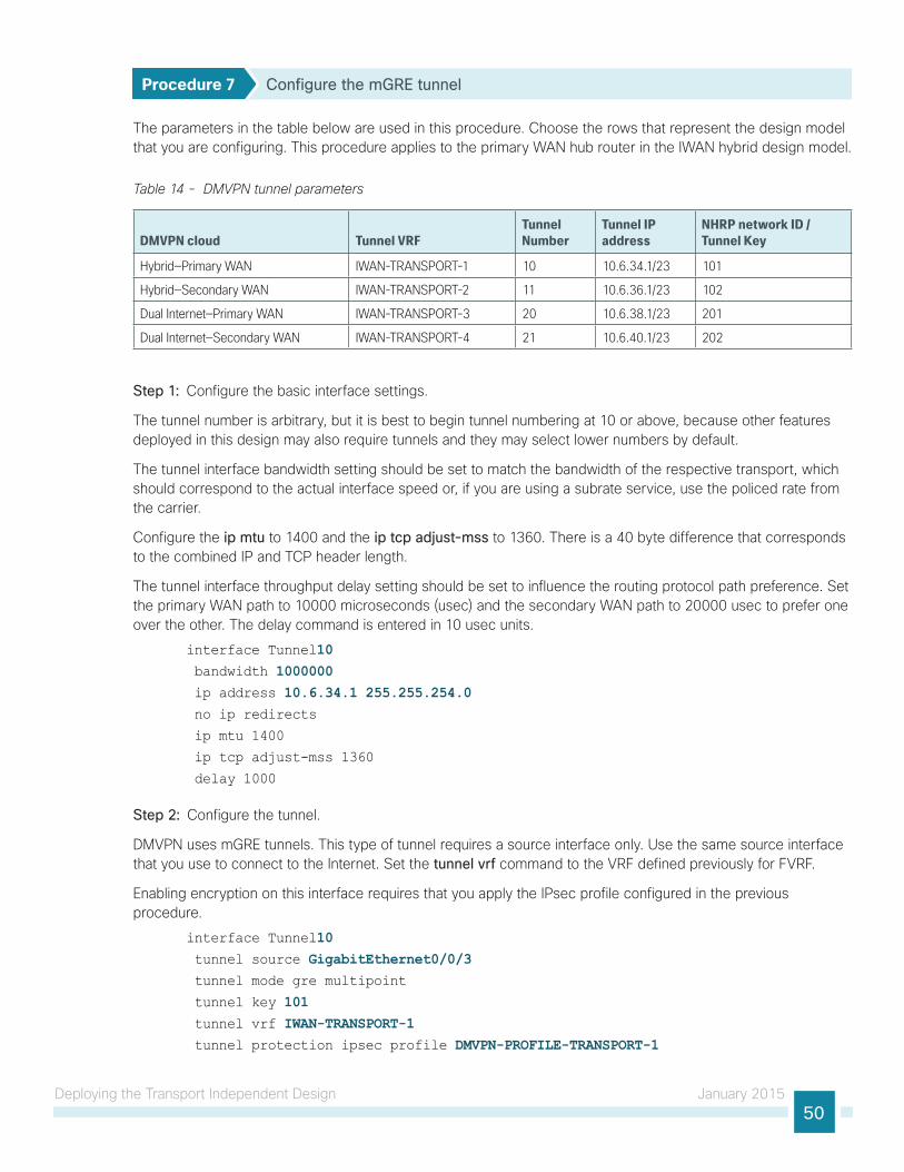
Deploying the Transport Independent Design January 201550
Procedure 7 Configure the mGRE tunnel
The parameters in the table below are used in this procedure. Choose the rows that represent the design model that you are configuring. This procedure applies to the primary WAN hub router in the IWAN hybrid design model.
Table 14 - DMVPN tunnel parameters
DMVPN cloud Tunnel VRFTunnel Number
Tunnel IP address
NHRP network ID / Tunnel Key
Hybrid—Primary WAN IWAN-TRANSPORT-1 10 10.6.34.1/23 101
Hybrid—Secondary WAN IWAN-TRANSPORT-2 11 10.6.36.1/23 102
Dual Internet—Primary WAN IWAN-TRANSPORT-3 20 10.6.38.1/23 201
Dual Internet—Secondary WAN IWAN-TRANSPORT-4 21 10.6.40.1/23 202
Step 1: Configure the basic interface settings.
The tunnel number is arbitrary, but it is best to begin tunnel numbering at 10 or above, because other features deployed in this design may also require tunnels and they may select lower numbers by default.
The tunnel interface bandwidth setting should be set to match the bandwidth of the respective transport, which should correspond to the actual interface speed or, if you are using a subrate service, use the policed rate from the carrier.
Configure the ip mtu to 1400 and the ip tcp adjust-mss to 1360. There is a 40 byte difference that corresponds to the combined IP and TCP header length.
The tunnel interface throughput delay setting should be set to influence the routing protocol path preference. Set the primary WAN path to 10000 microseconds (usec) and the secondary WAN path to 20000 usec to prefer one over the other. The delay command is entered in 10 usec units.
interface Tunnel10 bandwidth 1000000 ip address 10.6.34.1 255.255.254.0 no ip redirects
ip mtu 1400
ip tcp adjust-mss 1360
delay 1000
Step 2: Configure the tunnel.
DMVPN uses mGRE tunnels. This type of tunnel requires a source interface only. Use the same source interface that you use to connect to the Internet. Set the tunnel vrf command to the VRF defined previously for FVRF.
Enabling encryption on this interface requires that you apply the IPsec profile configured in the previous procedure.
interface Tunnel10 tunnel source GigabitEthernet0/0/3 tunnel mode gre multipoint
tunnel key 101 tunnel vrf IWAN-TRANSPORT-1 tunnel protection ipsec profile DMVPN-PROFILE-TRANSPORT-1

Deploying the Transport Independent Design January 201551
Step 3: Configure NHRP.
The DMVPN hub router acts in the role of NHRP server for all of the spokes. NHRP is used by remote routers to determine the tunnel destinations for peers attached to the mGRE tunnel.
NHRP requires all devices within a DMVPN cloud to use the same network ID and authentication key. The NHRP cache holdtime should be configured to 600 seconds.
EIGRP (configured in the following procedure) relies on a multicast transport and requires NHRP to automatically add routers to the multicast NHRP mappings.
The ip nhrp redirect command allows the DMVPN hub to notify spoke routers that a more optimal path may exist to a destination network, which may be required for DMVPN spoke-spoke direct communications.
interface Tunnel10 ip nhrp authentication cisco123 ip nhrp map multicast dynamic
ip nhrp network-id 101 ip nhrp holdtime 600
ip nhrp redirect
Step 4: Enable PIM non-broadcast multiple access (NBMA) mode for the DMVPN tunnel.
Spoke-to-spoke DMVPN networks present a unique challenge because the spokes cannot directly exchange information with one another, even though they are on the same logical network. This inability to directly exchange information can also cause problems when running IP Multicast.
To resolve this issue requires a method where each remote PIM neighbor has its join messages tracked separately. A router in PIM NBMA mode treats each remote PIM neighbor as if it were connected to the router through a point-to-point link.
Do not enable PIM on the Internet DMZ interface, as no multicast traffic should be requested from this interface.
Tech Tip
interface Tunnel10 ip pim sparse-mode
ip pim nbma-mode
Procedure 8 Configure EIGRP
Step 1: Configure the EIGRP values for the mGRE tunnel interface.
Spoke-to-spoke DMVPN networks present a unique challenge because the spokes cannot directly exchange information with one another, even though they are on the same logical network. This limitation requires that the DMVPN hub router advertise routes from other spokes on the same network. This advertisement of these routes would normally be prevented by split horizon and can be overridden by the no split-horizon command.
The EIGRP hello interval is increased to 20 seconds and the EIGRP hold time is increased to 60 seconds in order to accommodate up to 2000 remote sites on a single DMVPN cloud.

Deploying the Transport Independent Design January 201552
Increasing the EIGRP timers also slows down the routing convergence to improve network stability and the IWAN design allows PfR to initiate the fast failover, so changing the timers is recommended for all IWAN deployments.
router eigrp IWAN-EIGRP address-family ipv4 unicast autonomous-system 400 af-interface Tunnel10 hello-interval 20 hold-time 60 no passive-interface
no split-horizon
exit-af-interface
exit-address-family
Step 2: Configure EIGRP neighbor authentication. Neighbor authentication enables the secure establishment of peering adjacencies and exchange route tables over the DMVPN tunnel interface.
key chain WAN-KEY key 1
key-string c1sco123
router eigrp IWAN-EIGRP address-family ipv4 unicast autonomous-system 400 af-interface Tunnel10 authentication mode md5
authentication key-chain WAN-KEY no passive-interface
exit-af-interface
exit-address-family
Step 3: Tag and filter the routes.
This design uses a single EIGRP autonomous system for the WAN and all of the WAN remote sites. Every remote site is dual connected for resiliency. However, due to the multiple paths that exist within this topology, you must try to avoid routing loops and to prevent remote sites from becoming transit sites if WAN failures were to occur.
In this design, there is a separate IP subnet for each DMVPN network and the EIGRP tags are defined as the NHRP network ID to help with readability and troubleshooting.
The following logic is used to control the routing.
• Each DMVPN network will have a unique EIGRP route tag to prevent routes from being re-advertised over the other DMVPN network.
• All prefixes that are advertised towards the WAN are tagged with the NHRP network ID of the DMVPN hub that advertises the route.
• All DMVPN learned WAN prefixes, except those that originate locally from a hub, are advertised towards the LAN and tagged with the DMVPN NHRP network ID of the hub that advertises the route.
• The IWAN design always uses DMVPN hub routers in pairs. Each DMVPN hub router blocks DMVPN WAN routes from the LAN that are tagged with the opposite hub’s DMVPN NHRP network ID.
Outbound distribute-lists are used to set tags on the DMVPN hub routers towards the WAN and LAN. The remote-site routers use the tags set towards the WAN in order to protect against becoming transit sites.

Deploying the Transport Independent Design January 201553
The DMVPN hub routers use an inbound distribute-list in order to limit which routes are accepted for installation into the route table. These routers are configured to only accept routes that do not originate from the MPLS and DMVPN WAN sources. To accomplish this task, during the route redistribution process, the DMVPN hub router must explicitly tag the DMVPN learned WAN routes. The following tables show specific route tags in use.
Table 15 - Route tag information for DMVPN IWAN hybrid hub routers
DMVPN Hub DMVPN prefix (tag) Tag Tunnel Tag LAN Block LAN
VPN-MPLS-ASR1002X-1
101 (MPLS) 101 (All routes)
101 (WAN routes)
102 (INET Tagged)
VPN-INET-4451X-2 102 (INET) 102 (All routes)
102 (WAN routes)
101 (MPLS Tagged)
Table 16 - Route tag information for DMVPN IWAN dual Internet hub routers
DMVPN Hub DMVPN prefix (tag) Tag Tunnel Tag LAN Block LAN
VPN-INET-ASR1002X-3
201 (INET1) 201 (All routes)
201 (WAN routes)
202 (INET2 Tagged)
VPN-INET-ASR1002X-4
202 (INET2) 202 (All routes)
202 (WAN routes)
201 (INET1 Tagged)
The following examples show both DMVPN hub routers in the IWAN hybrid design model.
Example: VPN-MPLS-ASR1002X-1route-map SET-TAG-ALL permit 10 description tag all routes advertised through the tunnel set tag 101
! All MPLS tunnel interfaces are in this IP address range
ip access-list standard DMVPN-1-SPOKES permit 10.6.34.0 0.0.1.255
route-map SET-TAG-DMVPN-1 permit 10 description Tag routes sourced from DMVPN-1 match ip route-source DMVPN-1-SPOKES set tag 101route-map SET-TAG-DMVPN-1 permit 100 description Advertise all other routes with no tag
route-map BLOCK-DMVPN-2 deny 10 description Do not advertise routes sourced from DMVPN-2 match tag 102route-map BLOCK-DMVPN-2 permit 100
router eigrp IWAN-EIGRP address-family ipv4 unicast autonomous-system 400 topology base
distribute-list route-map SET-TAG-DMVPN-1 out Port-channel1

Deploying the Transport Independent Design January 201554
distribute-list route-map SET-TAG-ALL out Tunnel10 distribute-list route-map BLOCK-DMVPN-2 in Port-channel1
Example: VPN-INET-ISR4451X-2route-map SET-TAG-ALL permit 10 description tag all routes advertised through the tunnel set tag 102
! All INET tunnel interfaces are in this IP address range
ip access-list standard DMVPN-2-SPOKES permit 10.6.36.0 0.0.1.255
route-map SET-TAG-DMVPN-2 permit 10 description Tag routes sourced from DMVPN-2 match ip route-source DMVPN-2-SPOKES set tag 102route-map SET-TAG-DMVPN-2 permit 100 description Advertise all other routes with no tag
route-map BLOCK-DMVPN-1 deny 10 description Do not advertise routes sourced from DMVPN-1 match tag 101route-map BLOCK-DMVPN-1 permit 100
router eigrp IWAN-EIGRP address-family ipv4 unicast autonomous-system 400 topology base
distribute-list route-map SET-TAG-DMVPN-2 out Port-channel2 distribute-list route-map SET-TAG-ALL out Tunnel11 distribute-list route-map BLOCK-DMVPN-1 in Port-channel2

Deploying the Transport Independent Design January 201555
Configuring the Firewall and DMZ Switch
1. Configure the DMZ switch for DMVPN hub router
2. Configure the DMZ switch for IOS CA
3. Configure firewall DMZ interface
4. Configure network address translation
5. Configure security policy
PR
OC
ESS
If necessary, configure the DMZ and firewall for the Internet WAN.
Procedure 1 Configure the DMZ switch for DMVPN hub router
This procedure assumes that the switch has already been configured following the guidance in the Campus Wired LAN Technology Design Guide. Only the procedures required to support the integration of the firewall into the deployment are included.
Reader Tip
Step 1: Set the DMZ switch to be the spanning tree root for the VLAN that contains the DMVPN hub router.
vlan 1118 name dmz-vpn
spanning-tree vlan 1118 root primary
Step 2: Configure the interface that is connected to the DMVPN hub routers. Repeat as necessary.
interface GigabitEthernet1/0/1 description VPN-INET-4451X-2 (gig0/0/3) switchport access vlan 1118 switchport host
logging event link-status
load-interval 30
no shutdown
macro apply EgressQoS

Deploying the Transport Independent Design January 201556
Step 3: Configure the interfaces that are connected to the appliances as a trunk.
interface GigabitEthernet1/0/48 description IE-ASA5545Xa Gig0/1
interface GigabitEthernet2/0/48 description IE-ASA5545Xb Gig0/1
interface range GigabitEthernet1/0/48, GigabitEthernet2/0/48 switchport trunk allowed vlan add 1118 switchport mode trunk
logging event link-status
logging event trunk-status
load-interval 30
no shutdown
macro apply EgressQoS
Procedure 2 Configure the DMZ switch for IOS CA
If you are using an IOS CA, configure the DMZ switch with the VLAN, port, and trunks.
Step 1: Configure the interface that is connected to the IOS CA.
interface GigabitEthernet1/0/20 description IWAN-IOS-CA (gig 0/1) switchport access vlan 1116 switchport mode access
logging event trunk-status
spanning-tree portfast
Step 2: Configure the interfaces that are connected to the appliances.
interface range GigabitEthernet1/0/48, GigabitEthernet2/0/48 switchport trunk allowed vlan add 1116
Procedure 3 Configure firewall DMZ interface
The firewall’s DMZ is a portion of the network where, typically, traffic to and from other parts of the network is tightly restricted. Organizations place network services in a DMZ for exposure to the Internet. These servers are typically not allowed to initiate connections to the ‘inside’ network, except for specific circumstances.
The DMZ network is connected to the appliances on the appliances’ GigabitEthernet interface via a VLAN trunk to allow the greatest flexibility if new VLANs must be added to connect additional DMZs. The trunk connects the appliances to a 2960X access-switch stack to provide resiliency. The DMZ VLAN interfaces on the Cisco ASA are each assigned an IP address, which will be the default gateway for each of the VLAN subnets.

Deploying the Transport Independent Design January 201557
The DMZ switch only offers Layer 2 switching capability; the DMZ switch’s VLAN interfaces do not have an IP address assigned, save for one VLAN interface with an IP address for management of the switch.
Figure 21 - DMZ VLAN topology and services
30
09
DMZ VLANTrunk
DMVPNHub Router
DMZSwitch
DistributionSwitch
Cisco ASA
Internet
By setting the DMZ connectivity as a VLAN trunk, you get the greatest flexibility.
Tech Tip
Step 1: In Configuration > Device Setup > Interfaces, click the interface that is connected to the DMZ switch. (Example: GigabitEthernet0/1)
Step 2: Click Edit.
Step 3: Select Enable Interface, and then click OK.
Step 4: On the Interface pane, click Add > Interface.
Step 5: In the Hardware Port list choose the interface configured in Step 1. (Example: GigabitEthernet0/1)
Step 6: In the VLAN ID box, enter the VLAN number for the DMZ VLAN. (Example: 1118)
Step 7: In the Subinterface ID box, enter the VLAN number for the DMZ VLAN. (Example: 1118)
Step 8: Enter an Interface Name. (Example: dmz-dmvpn)
Step 9: In the Security Level box, enter a value of 75.
Step 10: Enter the interface IP Address. (Example: 192.168.146.1)
Step 11: Enter the interface Subnet Mask, and then click OK. (Example: 255.255.255.0)

Deploying the Transport Independent Design January 201558
Step 12: Click Apply.
Step 13: In Configuration > Device Management > High Availability > click Failover.
Step 14: On the Interfaces tab, for the interface created in Step 4, enter the IP address of the standby unit in the Standby IP address column. (Example: 192.168.146.2)
Step 15: Select Monitored.
Step 16: Click Apply.

Deploying the Transport Independent Design January 201559
Step 17: (Optional) Repeat this procedure for the IOS CA VLAN by using the appropriate information.
Procedure 4 Configure network address translation
The DMZ network uses private network (RFC 1918) addressing that is not Internet routable, so the firewall must translate the DMZ address of the DMVPN hub router to an outside public address.
The example DMZ address to public IP address mapping is shown in the following table.
Table 17 - DMVPN NAT address mapping
DMVPN DMVPN hub router DMZ address DMVPN hub router public address (externally routable after NAT)
IWAN-TRANSPORT-2 192.168.146.10 172.16.140.1 (ISP-A)
IWAN-TRANSPORT-3 192.168.146.20 172.16.140.11 (ISP-A)
IWAN-TRANSPORT-4 192.168.146.21 172.17.140.11 (ISP-B)
Table 18 - (Optional) IOS CA NAT address mapping
Device Name IOS CA router DMZ address IOS CA router public address (externally routable after NAT)
IWAN-IOS-CA 192.168.144.127 172.16.140.110 (ISP-A)
IWAN-IOS-CA 192.168.144.127 172.17.140.110 (ISP-B)

Deploying the Transport Independent Design January 201560
First, to simplify the configuration of the security policy, you create the External DMZ network objects that are used in the firewall policies.
Table 19 - External DMZ firewall network objects
Network object name Object type IP address Description
outside-dmvpn-2-ISPa Host 172.16.140.1 DMVPN hub router 2 on ISP A (outside)
outside-dmvpn-3-ISPa Host 172.16.140.11 DMVPN hub router 3 on ISP A (outside)
outside-dmvpn-4-ISPb Host 172.17.140.11 DMVPN hub router 4 on ISP B (outside)
outside-iwan-ios-ca-ISPa
(optional)
Host 172.16.140.110 IOS CA on ISP A for iWAN
outside-iwan-ios-ca-ISPb
(optional)
Host 172.17.140.110 IOS CA on ISP B for iWAN
Step 1: Navigate to Configuration > Firewall > Objects > Network Objects/Groups.
Step 2: Click Add > Network Object.
The Add Network Object dialog box appears.
Step 3: In the Name box, enter the name. (Example: outside-dmvpn-2-ISPa)
Step 4: In the Type list, choose Host or Network. (Example: Host)
Step 5: In the IP Address box, enter the address. (Example: 172.16.140.1)
Step 6: In the Description box, enter a useful description, and then click OK. (Example: DMVPN hub router 2 on ISP A)
Step 7: Repeat Step 2 through Step 6 for each object listed in Table 19. If an object already exists, then skip to the next object listed in the table.

Deploying the Transport Independent Design January 201561
Step 8: After adding all of the objects listed, click Apply on the Network Objects/Groups pane.
Next, you add a network object for the private DMZ address of the DMVPN hub router.
Table 20 - Private DMZ firewall network objects
Network object name Object type IP address Description
dmz-dmvpn-2 Host 192.168.146.10 DMVPN hub router 2 on vpn-dmz
dmz-dmvpn-3 Host 192.168.146.20 DMVPN hub router 3 on vpn-dmz
dmz-dmvpn-4 Host 192.168.146.21 DMVPN hub router 4 on vpn-dmz
dmz-iwan-ios-ca-ISPa
(optional)
Host 192.168.144.127 IOS CA on DMZ to ISP-A
dmz-iwan-ios-ca-ISPb
(optional)
Host 192.168.144.127 IOS CA on DMZ to ISP-B
Step 9: Navigate to Configuration > Firewall > Objects > Network Objects/Groups.
Step 10: Click Add > Network Object.
The Add Network Object dialog box appears.
Step 11: In the Name box, enter the name. (Example: dmz-dmvpn-2)
Step 12: In the Type list, choose Host or Network. (Example: Host)
Step 13: In the IP Address box, enter the address. (Example: 192.168.146.10)
Step 14: In the Description box, enter a useful description, and then click OK. (Example: DMVPN hub router 2 on vpn-dmz)
Step 15: Click the two down arrows. The NAT pane expands.
Step 16: Select Add Automatic Address Translation Rules.
Step 17: In the Translated Address list, choose the network object created previously. (Example: outside-dmvpn-2-ISPa)
Step 18: Select Use one-to-one address translation, and then click OK.
Step 19: Repeat Step 10 through Step 18 for each object listed in Table 20. If an object already exists, then skip to the next object listed in the table.

Deploying the Transport Independent Design January 201562
Step 20: After adding all of the objects listed, click Apply on the Network Objects/Groups pane.
Procedure 5 Configure security policy
The VPN DMZ provides an additional layer of protection to lower the likelihood of certain types of misconfiguration of the DMVPN routers exposing the business network to the Internet. A filter allows only DMVPN related traffic to reach the DMVPN hub routers from the DMVPN spoke routers on the Internet.
Step 1: Navigate to Configuration > Firewall > Access Rules.

Deploying the Transport Independent Design January 201563
Table 21 - Firewall policy rules for DMZ-VPN DMVPN hub routers
Interface Action Source Destination Service Description
Logging Enable / Level
Any Permit any4 dmz-vpn-network udp/ 4500 (required) Allow (non500-ISAKMP) traffic to the DMVPN hub routers
Selected / Default
Any Permit any4 dmz-vpn-network udp/isakmp (required) Allow ISAKMP (UDP500) traffic to the DMVPN hub routers
Selected / Default
Any Permit any4 dmz-vpn-network Esp (required) Allow ESP IP protocol 50 IPsec traffic to the DMVPN hub routers
Selected / Default
Any Permit any4 dmz-vpn-network icmp/echo (optional) Allow remote ping diagnostic traffic [ ICMP Type 0, Code 0 ]
Selected / Default
Any Permit any4 dmz-vpn-network icmp/echo reply (optional) Allow remote pings reply diagnostic traffic [ICMP Type 8, Code 0 ]
Selected / Default
Any Permit any4 dmz-vpn-network icmp/time-exceeded
(optional) ICMP Type 11, Code 0 Selected / Default
Any Permit any4 dmz-vpn-network icmp/port-unreachable
(optional) ICMP Type 3, Code 3 Selected / Default
Any Permit any4 dmz-vpn-network >udp/1023 (optional ) UDP high ports Selected / Default
Any Permit any4 dmz-networks tcp/http (optional) IOS CA Port 80 traffic Selected / Default
Step 2: Click the rule that denies traffic from the DMZ toward other networks.
Be sure to perform this step for every rule listed in the previous table. Inserting the rules above the DMZ-to-any rule keeps the added rules in the same order as listed, which is essential for the proper execution of the security policy.
Caution
Step 3: Click Add > Insert.
The Add Access Rule dialog box appears.
Step 4: In the Interface list, choose the interface. (Example: Any)
Step 5: For the Action option, select the action. (Example: Permit)
Step 6: In the Source box, choose the source. (Example: any4)
Step 7: In the Destination box, choose the destination. (Example: dmz-vpn-network)

Deploying the Transport Independent Design January 201564
Step 8: In the Service box, enter the service. (Example: udp/4500)
Step 9: In the Description box, enter a useful description. (Example: Allow (non500-ISAKMP) traffic to the DMVPN hub routers)
Step 10: Select or clear Enable Logging. (Example: Selected)
Step 11: In the Logging Level list, choose the logging level value, and then click OK. (Example: Default)
.
Step 12: Repeat Step 2 through Step 11 for all rules listed in Table 21.
Step 13: After adding all of the rules in the order listed, click Apply on the Access Rules pane.
Figure 22 - Firewall rules summary

Deploying the Transport Independent Design January 201565
Configuring Remote-Site DMVPN Router
1. Configure the WAN remote site router
2. Configure the WAN-facing VRF
3. Connect to the MPLS WAN or Internet
4. Configure IKEv2 and IPsec
5. Configure the mGRE Tunnel
6. Configure EIGRP
7. Configure IP multicast routing
8. Connect router to access layer switch
9. Configure access layer routing
PR
OC
ESS
These procedures describe configuring a single-router, dual-link design. You also use them when configuring the first router of a dual-router, dual-link design.

Deploying the Transport Independent Design January 201566
Refer to the following flowchart to help you navigate through the required procedures for your environment.
Figure 23 - Remote-site DMVPN router configuration flowchart
12
37
1. Configure the WAN Remote Site Router2. Configure the WAN-facing VRF3. Connect to the MPLS WAN or Internet4. Configure IKEv2 and IPSec5. Configure mGRE Tunnel6. Configure EIGRP7. Configure IP Multicast Routing
1. Configure Access Layer HSRP2. Configure Transit Network3. Configure EIGRP on the Transit Network4. Enable Enhanced Object Tracking
1. Connect Router to Distribution Layer2. Configure EIGRP for Distribution Layer Link
Remote Site Routerto Distribution Layer
Remote-Site DMVPN Router
ConfigurationProcedures
9. Configure Access Layer Routing
3. Configure Transit Network for Dual Router Design
YESNO
NO YES YESNO
Dual Router Design Modification Procedures for 1st Router
8. Connect Router to Access Layer Switch
1 Configure the WAN Rem
YESNO
mote Site RouterRem
nfigure EIGRPnfigure IP Multicast Routing
12
h
1. Configure Access L
NO YESDual RouterDesign?
Dual RouterDesign?
12
37
Configure 2nd Routerat Remote Site
Configure 2nd Router at Remote Site
Remote-Site DMVPNSingle Router, Dual Link
Remote-Site DMVPN RouterDual Router, Dual Link (1st Router)
Distribution Layer
Design?
CoConfigure 2nd DMVPN for a Single Router
Remote Site
CoConfigure 2nd DMVPN for a Single Router
Remote Site
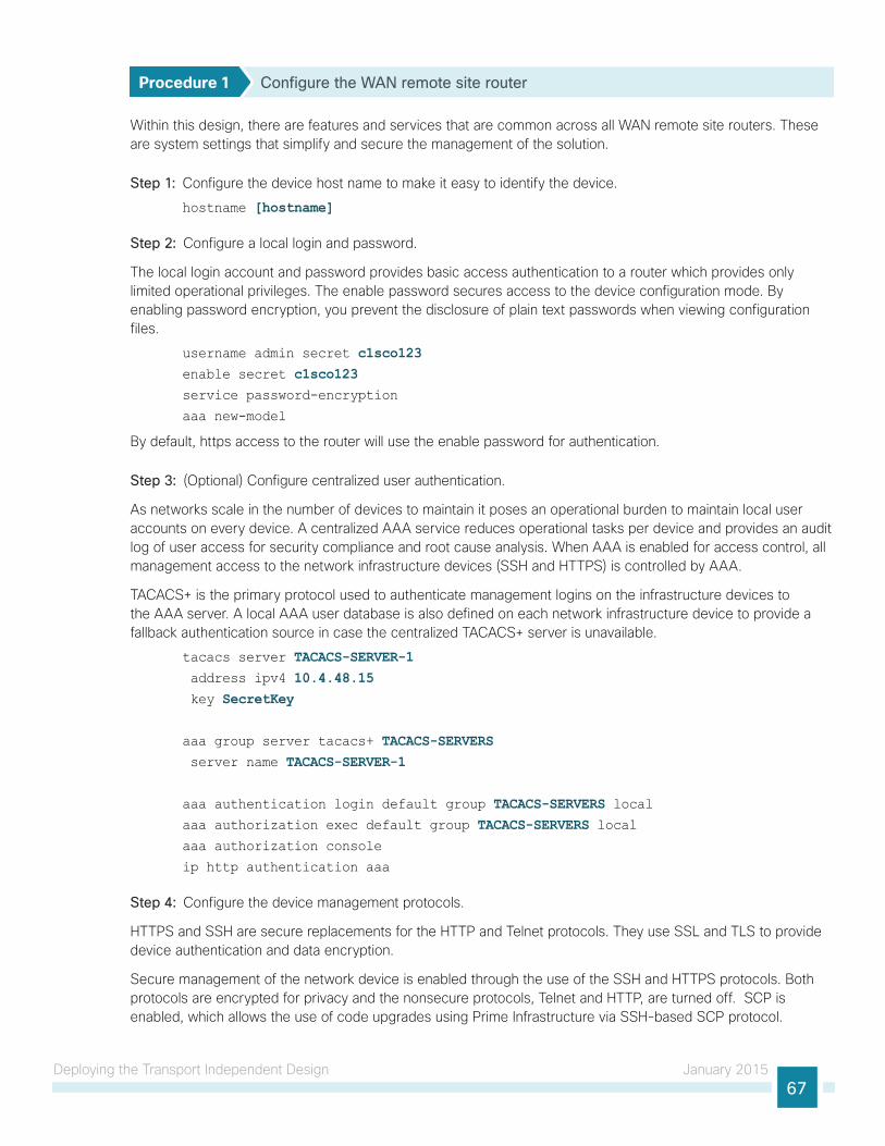
Deploying the Transport Independent Design January 201567
Procedure 1 Configure the WAN remote site router
Within this design, there are features and services that are common across all WAN remote site routers. These are system settings that simplify and secure the management of the solution.
Step 1: Configure the device host name to make it easy to identify the device.
hostname [hostname]
Step 2: Configure a local login and password.
The local login account and password provides basic access authentication to a router which provides only limited operational privileges. The enable password secures access to the device configuration mode. By enabling password encryption, you prevent the disclosure of plain text passwords when viewing configuration files.
username admin secret c1sco123enable secret c1sco123service password-encryption
aaa new-model
By default, https access to the router will use the enable password for authentication.
Step 3: (Optional) Configure centralized user authentication.
As networks scale in the number of devices to maintain it poses an operational burden to maintain local user accounts on every device. A centralized AAA service reduces operational tasks per device and provides an audit log of user access for security compliance and root cause analysis. When AAA is enabled for access control, all management access to the network infrastructure devices (SSH and HTTPS) is controlled by AAA.
TACACS+ is the primary protocol used to authenticate management logins on the infrastructure devices to the AAA server. A local AAA user database is also defined on each network infrastructure device to provide a fallback authentication source in case the centralized TACACS+ server is unavailable.
tacacs server TACACS-SERVER-1 address ipv4 10.4.48.15 key SecretKey
aaa group server tacacs+ TACACS-SERVERS server name TACACS-SERVER-1
aaa authentication login default group TACACS-SERVERS localaaa authorization exec default group TACACS-SERVERS localaaa authorization console
ip http authentication aaa
Step 4: Configure the device management protocols.
HTTPS and SSH are secure replacements for the HTTP and Telnet protocols. They use SSL and TLS to provide device authentication and data encryption.
Secure management of the network device is enabled through the use of the SSH and HTTPS protocols. Both protocols are encrypted for privacy and the nonsecure protocols, Telnet and HTTP, are turned off. SCP is enabled, which allows the use of code upgrades using Prime Infrastructure via SSH-based SCP protocol.

Deploying the Transport Independent Design January 201568
Specify the transport preferred none on vty lines to prevent errant connection attempts from the CLI prompt. Without this command, if the ip name-server is unreachable, long timeout delays may occur for mistyped commands.
ip domain-name cisco.localip ssh version 2
no ip http server
ip http secure-server
ip scp server enable
line vty 0 15
transport input ssh
transport preferred none
Step 5: When synchronous logging of unsolicited messages and debug output is turned on, console log messages are displayed on the console after interactive CLI output is displayed or printed. With this command, you can continue typing at the device console when debugging is enabled.
line con 0
transport preferred none
logging synchronous
Step 6: Enable SNMP. This allows the network infrastructure devices to be managed by a NMS. SNMPv2c is configured both for a read-only and a read-write community string.
snmp-server community cisco RO snmp-server community cisco123 RWsnmp-server ifindex persist ! IOS Classic Only
snmp ifmib ifindex persist ! IOS XE Only
Step 7: (Optional) In networks where network operational support is centralized you can increase network security by using an access list to limit the networks that can access your device. In this example, only devices on the 10.4.48.0/24 network will be able to access the device via SSH or SNMP.
access-list 55 permit 10.4.48.0 0.0.0.255line vty 0 15
access-class 55 in
snmp-server community cisco RO 55 snmp-server community cisco123 RW 55snmp-server ifindex persist ! IOS Classic Only
snmp ifmib ifindex persist ! IOS XE Only
If you configure an access-list on the vty interface you may lose the ability to use ssh to login from one router to the next for hop-by-hop troubleshooting.
Tech Tip
Step 8: Configure a synchronized clock.
NTP is designed to synchronize a network of devices. An NTP network usually gets its time from an authoritative time source, such as a radio clock or an atomic clock attached to a time server. NTP then distributes this time across the organizations network.

Deploying the Transport Independent Design January 201569
You should program network devices to synchronize to a local NTP server in the network. The local NTP server typically references a more accurate clock feed from an outside source. By configuring console messages, logs, and debug output to provide time stamps on output, you can cross-reference events in a network.
ntp server 10.4.48.17ntp update-calendar
clock timezone PST -8 clock summer-time PDT recurring
service timestamps debug datetime msec localtime
service timestamps log datetime msec localtime
Step 9: Configure an in-band management interface.
The loopback interface is a logical interface that is always reachable as long as the device is powered on and any IP interface is reachable to the network. Because of this capability, the loopback address is the best way to manage the router in-band. Layer 3 process and features are also bound to the loopback interface to ensure process resiliency.
The loopback address is commonly a host address with a 32-bit address mask. Allocate the loopback address from a unique network range that is not part of any other internal network summary range.
interface Loopback 0
ip address [ip address] 255.255.255.255 ip pim sparse-mode
The ip pim sparse-mode command will be explained in the next step.
Bind the device processes for SNMP, SSH, PIM, TACACS+ and NTP to the loopback interface address for optimal resiliency:
snmp-server trap-source Loopback0
ip ssh source-interface Loopback0
ip pim register-source Loopback0
ip tacacs source-interface Loopback0
ntp source Loopback0
Step 10: Configure IP Multicast routing.
In this design, which is based on sparse mode multicast operation, Auto RP is used to provide a simple yet scalable way to provide a highly resilient RP environment.
Enable IP Multicast routing on the platforms in the global configuration mode.
ip multicast-routing
Every Layer 3 switch and router must be configured to discover the IP Multicast RP with autorp. Use the ip pim autorp listener command to allow for discovery across sparse mode links. This configuration provides for future scaling and control of the IP Multicast environment and can change based on network needs and design.
ip pim autorp listener
All Layer 3 interfaces in the network must be enabled for sparse mode multicast operation.
ip pim sparse-mode

Deploying the Transport Independent Design January 201570
Procedure 2 Configure the WAN-facing VRF
You create a WAN-facing VRF in order to support FVRF for DMVPN. The VRF name is arbitrary, but it is useful to select a name that describes the VRF. The VRF must be enabled for IPv4.
Table 22 - VRF assignments
IWAN Design Model Primary WAN VRF Secondary WAN VRF
Hybrid IWAN-TRANSPORT-1 IWAN-TRANSPORT-2
Dual Internet IWAN-TRANSPORT-3 IWAN-TRANSPORT-4
This design uses VRF Lite, so the selection is only locally significant to the device. It is a best practice to use the same VRF/RD combination across multiple devices when using VRFs in a similar manner. However, this convention is not strictly required.
Step 1: Configure the primary WAN VRF.
Example: Primary WAN in the IWAN hybrid design modelvrf definition IWAN-TRANSPORT-1 address-family ipv4
Procedure 3 Connect to the MPLS WAN or Internet
The remote sites that are using DMVPN can use either static or dynamically assigned IP addresses. Cisco tested the design with static addresses for MPLS connections and DHCP assigned external addresses for Internet connections, which also provides a dynamically configured default route.
If you are using MPLS in this design, the DMVPN spoke router is connected to the service provider’s MPLS PE router. The IP addressing used between IWAN CE and MPLS PE routers must be negotiated with your MPLS carrier.
The DMVPN spoke router connects directly to the Internet without a separate firewall. This connection is secured in two ways. Because the Internet interface is in a separate VRF, no traffic can access the global VRF except traffic sourced through the DMVPN tunnel. This design provides implicit security. Additionally, an IP access list permits only the traffic required for an encrypted tunnel, as well as DHCP and various ICMP protocols for troubleshooting.
Option 1: MPLS WAN Physical WAN InterfaceThe DMVPN design uses FVRF, so you must place this interface into the VRF configured in the previous procedure.
Step 1: Enable the interface, select VRF, and assign the IP address.
Example: Primary WAN in IWAN hybrid design modelinterface GigabitEthernet0/0 vrf forwarding IWAN-TRANSPORT-1 ip address 192.168.6.5 255.255.255.252 no shutdown

Deploying the Transport Independent Design January 201571
Do not enable PIM on this interface, because no multicast traffic should be requested from this interface.
Step 2: Configure the VRF-specific default routing.
The VRF created for FVRF must have its own default route to the Internet. This default route points to the MPLS PE router’s IP address and is used by DMVPN for tunnel establishment.
ip route vrf IWAN-TRANSPORT-1 0.0.0.0 0.0.0.0 192.168.6.6
Option 2: Internet WAN Physical WAN InterfaceThe DMVPN design uses FVRF, so you must place this interface into the VRF configured in the previous procedure.
Step 1: Enable the interface, select VRF, and enable DHCP.
Example: Primary WAN in IWAN dual Internet design modelinterface GigabitEthernet0/0 vrf forwarding IWAN-TRANSPORT-3 ip address dhcp
no cdp enable
no shutdown
Do not enable PIM on this interface, because no multicast traffic should be requested from this interface.
Step 2: Configure and apply the access list.
The IP access list must permit the protocols specified in the following table. The access list is applied inbound on the WAN interface, so filtering is done on traffic destined to the router.
Table 23 - Required DMVPN protocols
Name Protocol Usage
non500-isakmp UDP 4500 IPsec via NAT-T
isakmp UDP 500 ISAKMP
esp IP 50 IPsec
bootpc UDP 68 DHCP
Example: Primary WAN in IWAN dual Internet design modelinterface GigabitEthernet0/0 ip access-group ACL-INET-PUBLIC in
ip access-list extended ACL-INET-PUBLIC permit udp any any eq non500-isakmp
permit udp any any eq isakmp
permit esp any any
permit udp any any eq bootpc

Deploying the Transport Independent Design January 201572
The additional protocols listed in the following table may assist in troubleshooting, but are not explicitly required to allow DMVPN to function properly.
Table 24 - Optional protocols: DMVPN spoke router
Name Protocol Usage
icmp echo ICMP Type 0, Code 0 Allow remote pings
icmp echo-reply ICMP Type 8, Code 0 Allow ping replies (from your requests)
icmp ttl-exceeded ICMP Type 11, Code 0 Allow traceroute replies (from your requests)
icmp port-unreachable ICMP Type 3, Code 3 Allow traceroute replies (from your requests)
UDP high ports UDP > 1023, TTL=1 Allow remote traceroute
IOS CA Port 80 172.16.140.110 on TCP / 80 Allow IOS CA to communicate with router during enrollment
The additional optional entries for an access list to support ping are as follows:
permit icmp any any echo
permit icmp any any echo-reply
The additional optional entries for an access list to support traceroute are as follows:
permit icmp any any ttl-exceeded ! for traceroute (sourced)
permit icmp any any port-unreachable ! for traceroute (sourced)
permit udp any any gt 1023 ttl eq 1 ! for traceroute (destination)
The additional optional entry for an access list to support IOS CA at the Internet DMZ address 172.16.140.11 on source port 80 is as follows:
permit tcp host 172.16.140.110 eq www any
Procedure 4 Configure IKEv2 and IPsec
The parameters in the tables below are used in this procedure. Choose the table that represents the design model that you are configuring. This procedure applies to the Primary WAN.
Table 25 - Crypto parameters: IWAN hybrid design model
Parameter Primary WAN Secondary WAN
vrf IWAN-TRANSPORT-1 IWAN-TRANSPORT-2
crypto ikev2 keyring DMVPN-KEYRING-1 DMVPN-KEYRING-2
crypto ikev2 profile FVRF-IKEv2-IWAN-TRANSPORT-1 FVRF-IKEv2-IWAN-TRANSPORT-2
crypto ipsec profile DMVPN-PROFILE-TRANSPORT-1 DMVPN-PROFILE-TRANSPORT-2

Deploying the Transport Independent Design January 201573
Table 26 - Crypto parameters: IWAN dual Internet design model
Parameter Primary WAN Secondary WAN
vrf IWAN-TRANSPORT-3 IWAN-TRANSPORT-4
crypto ikev2 keyring DMVPN-KEYRING-3 DMVPN-KEYRING-4
crypto ikev2 profile FVRF-IKEv2-IWAN-TRANSPORT-3 FVRF-IKEv2-IWAN-TRANSPORT-4
crypto ipsec profile DMVPN-PROFILE-TRANSPORT-3 DMVPN-PROFILE-TRANSPORT-4
IPsec uses a key exchange between the routers in order to encrypt/decrypt the traffic. These keys can be exchanged using a simple pre-sharing algorithm or a certificate authority. It is also possible to use a combination of the two, which is useful during a migration from one method to the other. Please choose one of the two options below as your method of key exchange.
Option 1: Configure with Pre-Shared Keys
Step 1: Configure the crypto keyring for pre-shared keys.
The crypto keyring defines a pre-shared key (or password) valid for IP sources that are reachable within a particular VRF. This key is a wildcard pre-shared key if it applies to any IP source. A wildcard key is configured using the 0.0.0.0 0.0.0.0 network/mask combination.
crypto ikev2 keyring [keyring name] peer ANY address 0.0.0.0 0.0.0.0 pre-shared-key [password]
Example: Primary WAN in the IWAN hybrid design modelcrypto ikev2 keyring DMVPN-KEYRING-1 peer ANY address 0.0.0.0 0.0.0.0 pre-shared-key c1sco123
Step 2: Configure the IKEv2 profile.
The default IKEv2 proposal is used, which includes the following:
• Encryption with AES cipher with a 256-bit key
• Integrity with SHA with 512-bit digest
• Pseudo-random function with SHA with 512-bit digest
• Diffie-Hellman group: 5
RS11-2921# show crypto ikev2 proposalIKEv2 proposal: default
Encryption: AES-CBC-256 AES-CBC-192 AES-CBC-128
Integrity : SHA512 SHA384 SHA256 SHA96 MD596
PRF : SHA512 SHA384 SHA256 SHA1 MD5
DH Group : DH_GROUP_1536_MODP/Group 5 DH_GROUP_1024_MODP/Group 2
The IKEv2 profile creates an association between an identity address, a VRF, and a crypto keyring. A wildcard address within a VRF is referenced with 0.0.0.0. The profile also defines what method of key sharing will be used on this router with authentication local and what methods will be accepted from remote locations with authentication remote.

Deploying the Transport Independent Design January 201574
The pre-share keyword is used with the keyring defined above.
crypto ikev2 profile [profile name] match fvrf [vrf name] match identity remote address [IP address] authentication remote pre-share
authentication local pre-share
keyring local [keyring name]
Example: Primary WAN in the IWAN hybrid design modelcrypto ikev2 profile FVRF-IKEv2-IWAN-TRANSPORT-1 match fvrf IWAN-TRANSPORT-1 match identity remote address 0.0.0.0 authentication remote pre-share
authentication local pre-share
keyring local DMVPN-KEYRING-1
Step 3: Confgure DPD.
DPD is essential in order to facilitate fast reconvergence and for spoke registration to function properly in case a DMVPN hub is restarted. The IWAN design recommends you set the remote site DPD timer to 40 seconds with 5 a second retry.
crypto ikev2 dpd [interval in seconds] [retry interval] on-demand
Examplecrypto ikev2 dpd 40 5 on-demand
Step 4: Define the IPsec transform set.
A transform set is an acceptable combination of security protocols, algorithms, and other settings to apply to IPsec-protected traffic. Peers agree to use a particular transform set when protecting a particular data flow.
The IPsec transform set for DMVPN uses the following:
• ESP with the 256-bit AES encryption algorithm
• ESP with the SHA (HMAC variant) authentication algorithm
Because the DMVPN hub router is behind a NAT device, the IPsec transform must be configured for transport mode.
crypto ipsec transform-set [transform set] esp-aes 256 esp-sha-hmac mode transport
Examplecrypto ipsec transform-set AES256/SHA/TRANSPORT esp-aes 256 esp-sha-hmac mode transport
Step 5: Configure the IPsec profile.
The IPsec profile creates an association between an IKEv2 profile and an IPsec transform-set.
crypto ipsec profile [profile name] set transform-set [transform set] set ikev2-profile [ikev2 profile name]

Deploying the Transport Independent Design January 201575
Example: Primary WAN in the IWAN hybrid design modelcrypto ipsec profile DMVPN-PROFILE-TRANSPORT-1 set transform-set AES256/SHA/TRANSPORT set ikev2-profile FVRF-IKEv2-IWAN-TRANSPORT-1
Step 6: Increase the IPsec anti-replay window size.
crypto ipsec security-association replay window-size 1024
QoS queuing delays can cause anti-replay packet drops, so it is important to extend the window size to prevent the drops from occurring.
Increasing the anti-replay window size has no impact on throughput and security. The impact on memory is insignificant because only an extra 128 bytes per incoming IPsec SA are needed.
It is recommended that you use the full 1024 window size to eliminate future anti-replay problems.
If you do not increase the window size, the router may drop packets and you may see the following error message on the router CLI:
%CRYPTO-4-PKT_REPLAY_ERR: decrypt: replay check failed
Tech Tip
Step 7: Proceed to Procedure 5, “Configure the mGRE Tunnel.”.
Option 2: Configure with a certificate authorityThe crypto pki trustpoint is the method of specifying the parameters associated with a CA. The router must authenticate to the CA first and then enroll with the CA in order to obtain its own identity certificate.
Step 1: The fingerprint command limits the responding CA. You can find this fingerprint by using show crypto pki server on the IOS CA.
IWAN-IOS-CA# show crypto pki server Certificate Server IWAN-IOS-CA:
Status: enabled
State: enabled
Server’s configuration is locked (enter "shut" to unlock it)
Issuer name: CN=IWAN-IOS-CA.cisco.local L=SanJose St=CA C=US
CA cert fingerprint: 75BEF625 9A9876CF 6F341FE5 86D4A5D8
Granting mode is: auto
Last certificate issued serial number (hex): 11
CA certificate expiration timer: 10:28:57 PST Nov 11 2017
CRL NextUpdate timer: 09:47:47 PST Dec 4 2014
Current primary storage dir: nvram:
Current storage dir for .crl files: nvram:
Database Level: Complete - all issued certs written as <serialnum>.cer

Deploying the Transport Independent Design January 201576
Table 27 - IOS CA IP address assignments
Network IP Address NAT IP Address
Internal 10.6.24.11 N/A
Internet DMZ 192.168.144.127 172.16.140.110 (ISP-A)
MPLS Provider 192.168.6.254 N/A
Step 2: Configure the PKI trust point.
crypto pki trustpoint [name] enrollment url [URL of IOS CA that is reachable] serial-number none
fqdn [fully qualified domain name of this router] ip-address [loopback IP address of this router] fingerprint [fingerprint from IOS CA] vrf [vrf name] revocation-check none
rsakeypair [name] 2048 2048
Example: RS11-2921This example is from a Primary WAN remote site router in the hybrid design model. This router can only reach the IOS CA from the MPLS provider cloud, and it uses the IP address 192.168.6.254 in VRF IWAN-TRANPORT-1 for enrollment.
crypto pki trustpoint IWAN-CA enrollment url http://192.168.6.254:80 serial-number none
fqdn RS11-2921.cisco.local ip-address 10.255.241.11 fingerprint 75BEF6259A9876CF6F341FE586D4A5D8 vrf IWAN-TRANSPORT-1 revocation-check none
rsakeypair IWAN-CA-KEYS 2048 2048
Example: RS14-2921-2This example is from the second remote site router in the dual Internet design model. This router can only reach the IOS CA from the Internet, and it uses the NAT IP address 172.16.140.110 in VRF IWAN-TRANPORT-4 for enrollment.
crypto pki trustpoint IWAN-CA enrollment url http://172.16.140.110:80 serial-number none
fqdn RS14-2921-2.cisco.local ip-address 10.255.244.14 fingerprint 75BEF6259A9876CF6F341FE586D4A5D8 vrf IWAN-TRANSPORT-4 revocation-check none
rsakeypair IWAN-CA-KEYS 2048 2048

Deploying the Transport Independent Design January 201577
Step 3: Authenticate to the CA and obtain the CA’s certificate
Exit the trustpoint configuration mode on the hub router and issue the following command to authenticate to the CA and get its certificate.
RS11-2921(config)# crypto pki authenticate IWAN-CACertificate has the following attributes:
Fingerprint MD5: 75BEF625 9A9876CF 6F341FE5 86D4A5D8
Fingerprint SHA1: 9C14D6F4 D1F08023 17A85669 52922632 C6B02928
Trustpoint Fingerprint: 75BEF625 9A9876CF 6F341FE5 86D4A5D8
Certificate validated - fingerprints matched.
Step 4: When the trustpoint CA certificate is accepted, enroll with the CA, enter a password for key retrieval and obtain a certificate for this hub router.
RS11-2921(config)# crypto pki enroll IWAN-CA% Start certificate enrollment ..
% Create a challenge password. You will need to verbally provide this
password to the CA Administrator in order to revoke your certificate.
For security reasons your password will not be saved in the configuration.
Please make a note of it.
Password: c1sco123Re-enter password: c1sco123
% The subject name in the certificate will include: RS11-2921.cisco.local
% The IP address in the certificate is 10.255.241.11
Request certificate from CA? [yes/no]: yes% Certificate request sent to Certificate Authority
% The ‘show crypto pki certificate verbose IWAN-CA’ commandwill show the
fingerprint.
Step 5: Configure the IKEv2 profile.
The default IKEv2 proposal is used, which includes the following:
• Encryption with AES cipher with a 256-bit key
• Integrity with SHA with 512-bit digest
• Pseudo-random function with SHA with 512-bit digest
• Diffie-Hellman group: 5
RS11-2921# show crypto ikev2 proposalIKEv2 proposal: default
Encryption: AES-CBC-256 AES-CBC-192 AES-CBC-128
Integrity : SHA512 SHA384 SHA256 SHA96 MD596
PRF : SHA512 SHA384 SHA256 SHA1 MD5
DH Group : DH_GROUP_1536_MODP/Group 5 DH_GROUP_1024_MODP/Group 2

Deploying the Transport Independent Design January 201578
The IKEv2 profile creates an association between an identity address, a VRF, and a crypto keyring. A wildcard address within a VRF is referenced with 0.0.0.0. The profile also defines what method of key sharing will be used on this router with authentication local and what methods will be accepted from remote locations with authentication remote. The rsa-sig keyword is used when certificates contain the encryption key.
crypto ikev2 profile [profile name] match fvrf [vrf name] match identity remote address [IP address] authentication remote rsa-sig
authentication local rsa-sig
pki trustpoint [trustpoint name]
Example: RS11-2921This example is from a Primary WAN remote site router in the IWAN hybrid design model.
crypto ikev2 profile FVRF-IKEv2-IWAN-TRANSPORT-1 match fvrf IWAN-TRANSPORT-1 match identity remote address 0.0.0.0 authentication remote rsa-sig
authentication local rsa-sig
pki trustpoint IWAN-CA
Example: RS14-2921-2This example is from a Secondary WAN remote site router in the dual Internet design model.
crypto ikev2 profile FVRF-IKEv2-IWAN-TRANSPORT-4 match fvrf IWAN-TRANSPORT-4 match identity remote address 0.0.0.0 authentication remote rsa-sig
authentication local rsa-sig
pki trustpoint IWAN-CA
Step 6: Configure DPD.
DPD is essential in order to facilitate fast reconvergence and for spoke registration to function properly in case a DMVPN hub is restarted. The IWAN design recommends you set the remote site DPD timer to 40 seconds with 5 a second retry.
crypto ikev2 dpd [interval in seconds] [retry interval] on-demand
Examplecrypto ikev2 dpd 40 5 on-demand
Step 7: Define the IPsec transform set.
A transform set is an acceptable combination of security protocols, algorithms, and other settings to apply to IPsec-protected traffic. Peers agree to use a particular transform set when protecting a particular data flow.
The IPsec transform set for DMVPN uses the following:
• ESP with the 256-bit AES encryption algorithm
• ESP with the SHA (HMAC variant) authentication algorithm

Deploying the Transport Independent Design January 201579
Because the DMVPN hub router is behind a NAT device, the IPsec transform must be configured for transport mode.
crypto ipsec transform-set [transform set] esp-aes 256 esp-sha-hmac mode transport
Examplecrypto ipsec transform-set AES256/SHA/TRANSPORT esp-aes 256 esp-sha-hmac mode transport
Step 8: Configure the IPSec profile.
The IPsec profile creates an association between an IKEv2 profile and an IPsec transform-set.
crypto ipsec profile [profile name] set transform-set [transform set] set ikev2-profile [ikev2 profile name]
Example: RS11-2921This example is from a Primary WAN remote site router in the IWAN hybrid design model.
crypto ipsec profile DMVPN-PROFILE-TRANSPORT-1 set transform-set AES256/SHA/TRANSPORT set ikev2-profile FVRF-IKEv2-IWAN-TRANSPORT-1
Example: RS14-2921-2This example is from a Secondary WAN remote site router in the dual Internet design model.
crypto ipsec profile DMVPN-PROFILE-TRANSPORT-4 set transform-set AES256/SHA/TRANSPORT set ikev2-profile FVRF-IKEv2-IWAN-TRANSPORT-4
Step 9: Increase the IPsec anti-replay window size.
crypto ipsec security-association replay window-size [value]
Examplecrypto ipsec security-association replay window-size 512
QoS queuing delays can cause anti-replay packet drops, so it is important to extend the window size in order to prevent the drops from occurring.
Increasing the anti-replay window size has no impact on throughput and security. The impact on memory is insignificant because only an extra 128 bytes per incoming IPsec SA is needed.
It is recommended that you use the maximum window size to eliminate future anti-replay problems. On the Cisco ASR 1000 router platform, the maximum replay window size is 512.
If you do not increase the window size, the router may drop packets and you may see the following error message on the router CLI:
%CRYPTO-4-PKT_REPLAY_ERR: decrypt: replay check failed
Tech Tip

Deploying the Transport Independent Design January 201580
Procedure 5 Configure the mGRE Tunnel
The parameters in the table below are used in this procedure. Choose the rows that represent the design model that you are configuring. This procedure applies to the Primary WAN remote site router in the IWAN hybrid design model.
Table 28 - DMVPN tunnel parameters
Design Model Tunnel VRFTunnel Number Tunnel Network
NHRP network ID / Tunnel Key
Hybrid—Primary WAN IWAN-TRANSPORT-1 10 10.6.34.0/23 101
Hybrid—Secondary WAN IWAN-TRANSPORT-2 11 10.6.36.0/23 102
Dual Internet—Primary WAN IWAN-TRANSPORT-3 20 10.6.38.0/23 201
Dual Internet—Secondary WAN IWAN-TRANSPORT-4 21 10.6.40.0/23 202
Step 1: Configure basic interface settings.
The tunnel number is arbitrary, but it is best to begin tunnel numbering at 10 or above, because other features deployed in this design may also require tunnels and they may select lower numbers by default.
You must set the bandwidth to match the bandwidth of the respective transport which corresponds to the actual interface speed. Or, if you are using a subrate service, use the policed rate from the carrier. QoS and PfR require the correct bandwidth setting in order to operate properly.
Configure the ip mtu to 1400 and the ip tcp adjust-mss to 1360. There is a 40 byte difference, which corresponds to the combined IP and TCP header length.
The tunnel interface throughput delay setting should be set to influence the routing protocol path preference. Set the primary WAN path to 10000 usec and the secondary WAN path to 20000 usec to prefer one over the other. The delay command is entered in 10 usec units.
interface Tunnel10 bandwidth 300000 ip address 10.6.34.11 255.255.254.0 no ip redirects
ip mtu 1400
ip tcp adjust-mss 1360
delay 1000
Step 2: Configure the tunnel.
DMVPN uses mGRE tunnels. This type of tunnel requires a source interface only. The source interface should be the same interface used in to connect to the MPLS or Internet connection. The tunnel vrf command should be set to the VRF defined previously for FVRF.

Deploying the Transport Independent Design January 201581
Enabling encryption on this interface requires the application of the IPsec profile configured in the previous procedure.
interface Tunnel10 tunnel source GigabitEthernet0/0 tunnel mode gre multipoint
tunnel key 101 tunnel vrf IWAN-TRANSPORT-1 tunnel protection ipsec profile DMVPN-PROFILE-TRANSPORT-1
Step 3: Configure NHRP.
The DMVPN hub router is the NHRP server for all of the spokes. Remote routers use NHRP in order to determine the tunnel destinations for peers attached to the mGRE tunnel.
The spoke router requires an additional configuration statement in order to define the NHRP server (NHS). This statement includes the NBMA definition for the DMVPN hub router tunnel endpoint. EIGRP relies on a multicast transport. Spoke routers require the NHRP multicast keyword in this statement.
The value used for the next hop server (NHS) is the mGRE tunnel address for the DMVPN hub router. The nbma entry must be set to either the MPLS DMVPN hub router’s actual public address or the outside NAT value of the DMVPN hub, as configured on the Cisco ASA 5500. This design uses the values shown in the following tables.
Table 29 - DMVPN tunnel NHRP parameters: IWAN hybrid design model
Transport 1 Transport 2
VRF IWAN-TRANSPORT-1 IWAN-TRANSPORT-2
DMVPN hub public address (actual) 192.168.6.1 192.168.146.10
DMVPN hub public address (externally routable after NAT) n/a (MPLS) 172.16.140.1
DMVPN hub tunnel IP address (NHS) 10.6.34.1 10.6.36.1
Tunnel number 10 11
NHRP network ID 101 102
Table 30 - DMVPN tunnel NHRP parameters: IWAN dual Internet design model
Transport 3 Transport 4
VRF IWAN-TRANSPORT-3 IWAN-TRANSPORT-4
DMVPN hub public address (actual) 192.168.146.20 192.168.146.21
DMVPN hub public address (externally routable after NAT) 172.16.140.11 172.17.140.11
DMVPN hub tunnel IP address (NHS) 10.6.38.1 10.6.40.1
Tunnel number 20 21
NHRP network ID 201 202
NHRP requires all devices within a DMVPN cloud to use the same network ID and authentication key. The NHRP cache holdtime should be configured to 600 seconds.
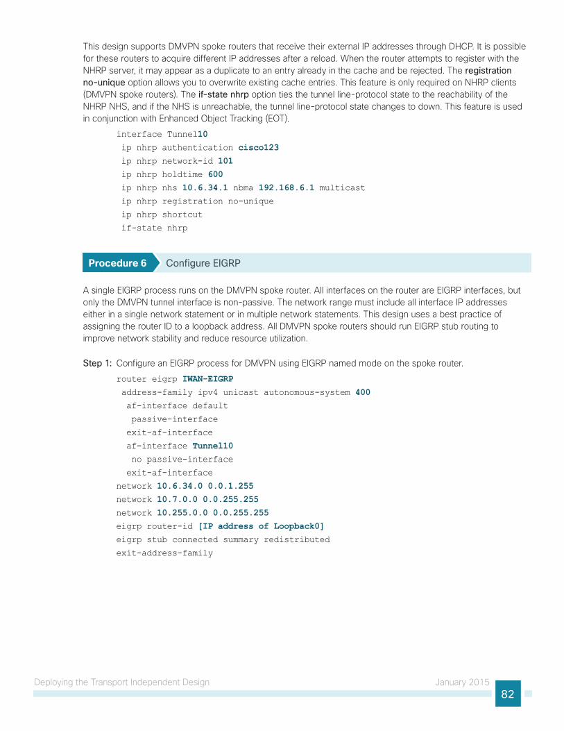
Deploying the Transport Independent Design January 201582
This design supports DMVPN spoke routers that receive their external IP addresses through DHCP. It is possible for these routers to acquire different IP addresses after a reload. When the router attempts to register with the NHRP server, it may appear as a duplicate to an entry already in the cache and be rejected. The registration no-unique option allows you to overwrite existing cache entries. This feature is only required on NHRP clients (DMVPN spoke routers). The if-state nhrp option ties the tunnel line-protocol state to the reachability of the NHRP NHS, and if the NHS is unreachable, the tunnel line-protocol state changes to down. This feature is used in conjunction with Enhanced Object Tracking (EOT).
interface Tunnel10 ip nhrp authentication cisco123 ip nhrp network-id 101 ip nhrp holdtime 600 ip nhrp nhs 10.6.34.1 nbma 192.168.6.1 multicast ip nhrp registration no-unique
ip nhrp shortcut
if-state nhrp
Procedure 6 Configure EIGRP
A single EIGRP process runs on the DMVPN spoke router. All interfaces on the router are EIGRP interfaces, but only the DMVPN tunnel interface is non-passive. The network range must include all interface IP addresses either in a single network statement or in multiple network statements. This design uses a best practice of assigning the router ID to a loopback address. All DMVPN spoke routers should run EIGRP stub routing to improve network stability and reduce resource utilization.
Step 1: Configure an EIGRP process for DMVPN using EIGRP named mode on the spoke router.
router eigrp IWAN-EIGRP address-family ipv4 unicast autonomous-system 400 af-interface default
passive-interface
exit-af-interface
af-interface Tunnel10 no passive-interface
exit-af-interface
network 10.6.34.0 0.0.1.255network 10.7.0.0 0.0.255.255network 10.255.0.0 0.0.255.255eigrp router-id [IP address of Loopback0]eigrp stub connected summary redistributed
exit-address-family

Deploying the Transport Independent Design January 201583
Step 2: Configure EIGRP values for the mGRE tunnel interface.
The EIGRP hello interval is increased to 20 seconds and the EIGRP hold time is increased to 60 seconds in order to accommodate up to 2000 remote sites on a single DMVPN cloud. Increasing the EIGRP timers also slows down the routing convergence in order to improve network stability and the IWAN design allows PfR to initiate the fast failover, so changing the timers is recommended for all IWAN deployments.
router eigrp IWAN-EIGRP address-family ipv4 unicast autonomous-system 400 af-interface Tunnel10 hello-interval 20 hold-time 60 exit-af-interface
exit-address-family
Step 3: Configure EIGRP neighbor authentication. Neighbor authentication enables the secure establishment of peering adjacencies and exchange route tables over the DMVPN tunnel interface.
key chain WAN-KEY key 1
key-string c1sco123
router eigrp IWAN-EIGRP address-family ipv4 unicast autonomous-system 400 af-interface Tunnel10 authentication mode md5
authentication key-chain WAN-KEY exit-af-interface
exit-address-family
Step 4: Configure EIGRP network summarization.
The remote-site LAN networks must be advertised. The IP assignment for the remote sites was designed so that all of the networks in use can be summarized within a single aggregate route. The summary address as configured below suppresses the more specific routes. If any network within the summary is present in the route table, the summary is advertised to the DMVPN hub, which offers a measure of resiliency. If the various LAN networks cannot be summarized, then EIGRP continues to advertise the specific routes.
router eigrp IWAN-EIGRP address-family ipv4 unicast autonomous-system 400 af-interface Tunnel10 summary-address [summary network] [summary mask] exit-af-interface
exit-address-family

Deploying the Transport Independent Design January 201584
Procedure 7 Configure IP multicast routing
This procedure includes additional steps for configuring IP Multicast for a DMVPN tunnel on a router with IP Multicast already enabled.
Step 1: Configure PIM on the DMVPN tunnel interface.
Enable IP PIM sparse mode on the DMVPN tunnel interface.
interface Tunnel10 ip pim sparse-mode
Step 2: Enable PIM non-broadcast multiple access mode for the DMVPN tunnel.
Spoke-to-spoke DMVPN networks present a unique challenge because the spokes cannot directly exchange information with one another, even though they are on the same logical network. This inability to directly exchange information can also cause problems when running IP Multicast.
To resolve the NBMA issue, you need to implement a method where each remote PIM neighbor has its join messages tracked separately. A router in PIM NBMA mode treats each remote PIM neighbor as if it were connected to the router through a point-to-point link.
interface Tunnel10 ip pim nbma-mode
Step 3: Configure the DR priority for the DMVPN spoke router.
Proper multicast operation across a DMVPN cloud requires that the hub router assumes the role of PIM designated router (DR). Spoke routers should never become the DR. You can prevent that by setting the DR priority to 0 for the spokes.
interface Tunnel10 ip pim dr-priority 0
Procedure 8 Connect router to access layer switch
OptionalIf you are using a remote-site distribution layer, skip to the “Deploying an IWAN Remote-Site Distribution Layer” section of this guide.
This guide includes only the steps needed in order to complete the access layer configuration. For complete access layer configuration details, refer to the Campus Wired LAN Technology Design Guide.
Reader Tip
Layer 2 EtherChannels are used to interconnect the CE router to the access layer in the most resilient method possible. If your access layer device is a single fixed configuration switch, a simple Layer 2 trunk between the router and switch is used.
In the access layer design, the remote sites use collapsed routing, with 802.1Q trunk interfaces to the LAN access layer. The VLAN numbering is locally significant only.

Deploying the Transport Independent Design January 201585
Option 1: Layer 2 EtherChannel from router to access layer switch
Step 1: Configure port-channel interface on the router.
interface Port-channel1 description EtherChannel link to RS12-A2960X no shutdown
Step 2: Configure EtherChannel member interfaces on the router.
Configure the physical interfaces to tie to the logical port-channel using the channel-group command. The number for the port-channel and channel-group must match. Not all router platforms can support LACP to negotiate with the switch, so EtherChannel is configured statically.
interface GigabitEthernet0/1 description RS12-A2960X Gig1/0/47
interface GigabitEthernet0/2 description RS12-A2960X Gig2/0/47
interface range GigabitEthernet0/1, GigabitEthernet0/2 no ip address
channel-group 1 no shutdown
Step 3: Configure EtherChannel member interfaces on the access layer switch.
Connect the router EtherChannel uplinks to separate switches in the access layer switch stack, or in the case of the Cisco Catalyst 4507R+E distribution layer, to separate redundant modules for additional resiliency.
The physical interfaces that are members of a Layer 2 EtherChannel are configured prior to configuring the logical port-channel interface. Doing the configuration in this order allows for minimal configuration and reduces errors because most of the commands entered to a port-channel interface are copied to its members interfaces and do not require manual replication.
Configure two physical interfaces to be members of the EtherChannel. Also, apply the egress QoS macro that was defined in the LAN switch platform configuration procedure to ensure traffic is prioritized appropriately.
Not all connected router platforms can support LACP to negotiate with the switch, so EtherChannel is configured statically.
interface GigabitEthernet1/0/47 description Link to RS12-2911-1 Gig0/1
interface GigabitEthernet2/0/47 description Link to RS12-2911-1 Gig0/2
interface range GigabitEthernet1/0/24, GigabitEthernet2/0/24 switchport
macro apply EgressQoS
channel-group 1 mode on logging event link-status
logging event trunk-status
logging event bundle-status

Deploying the Transport Independent Design January 201586
Step 4: Configure EtherChannel trunk on the access layer switch.
An 802.1Q trunk is used which allows the router to provide the Layer 3 services to all the VLANs defined on the access layer switch. The VLANs allowed on the trunk are pruned to only the VLANs that are active on the access layer switch. When using EtherChannel the interface type will be port-channel and the number must match the channel group configured in Step 3. DHCP Snooping and address resolution protocol (ARP) inspection are set to trust.
interface Port-channel1 description EtherChannel link to RS12-2911-1 switchport trunk allowed vlan 64,69 switchport mode trunk
ip arp inspection trust
spanning-tree portfast trunk
ip dhcp snooping trust
load-interval 30
no shutdown
The Cisco Catalyst 3750 Series Switch requires the switchport trunk encapsulation dot1q command
Option 2: Layer 2 trunk from router to access layer switch
Step 1: Enable the physical interface on the router.
interface GigabitEthernet0/2 description RS11-A2960X Gig1/0/48 no ip address
no shutdown
Step 2: Configure the trunk on the access layer switch.
Use an 802.1Q trunk for the connection, which allows the router to provide the Layer 3 services to all the VLANs defined on the access layer switch. The VLANs allowed on the trunk are pruned to only the VLANs that are active on the access switch. DHCP Snooping and ARP inspection are set to trust.
interface GigabitEthernet1/0/48 description Link to RS11-2921 Gig0/2 switchport trunk allowed vlan 64,69 switchport mode trunk
ip arp inspection trust
spanning-tree portfast trunk
logging event link-status
logging event trunk-status
ip dhcp snooping trust
load-interval 30
no shutdown
macro apply EgressQoS
The Cisco Catalyst 3750 Series Switch requires the switchport trunk encapsulation dot1q command.
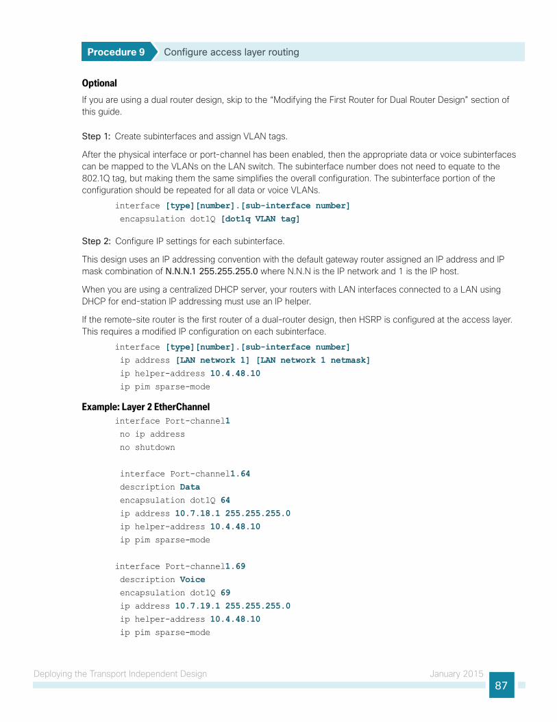
Deploying the Transport Independent Design January 201587
Procedure 9 Configure access layer routing
Optional If you are using a dual router design, skip to the “Modifying the First Router for Dual Router Design” section of this guide.
Step 1: Create subinterfaces and assign VLAN tags.
After the physical interface or port-channel has been enabled, then the appropriate data or voice subinterfaces can be mapped to the VLANs on the LAN switch. The subinterface number does not need to equate to the 802.1Q tag, but making them the same simplifies the overall configuration. The subinterface portion of the configuration should be repeated for all data or voice VLANs.
interface [type][number].[sub-interface number] encapsulation dot1Q [dot1q VLAN tag]
Step 2: Configure IP settings for each subinterface.
This design uses an IP addressing convention with the default gateway router assigned an IP address and IP mask combination of N.N.N.1 255.255.255.0 where N.N.N is the IP network and 1 is the IP host.
When you are using a centralized DHCP server, your routers with LAN interfaces connected to a LAN using DHCP for end-station IP addressing must use an IP helper.
If the remote-site router is the first router of a dual-router design, then HSRP is configured at the access layer. This requires a modified IP configuration on each subinterface.
interface [type][number].[sub-interface number] ip address [LAN network 1] [LAN network 1 netmask] ip helper-address 10.4.48.10 ip pim sparse-mode
Example: Layer 2 EtherChannelinterface Port-channel1 no ip address
no shutdown
interface Port-channel1.64 description Data encapsulation dot1Q 64 ip address 10.7.18.1 255.255.255.0 ip helper-address 10.4.48.10 ip pim sparse-mode
interface Port-channel1.69 description Voice encapsulation dot1Q 69 ip address 10.7.19.1 255.255.255.0 ip helper-address 10.4.48.10 ip pim sparse-mode
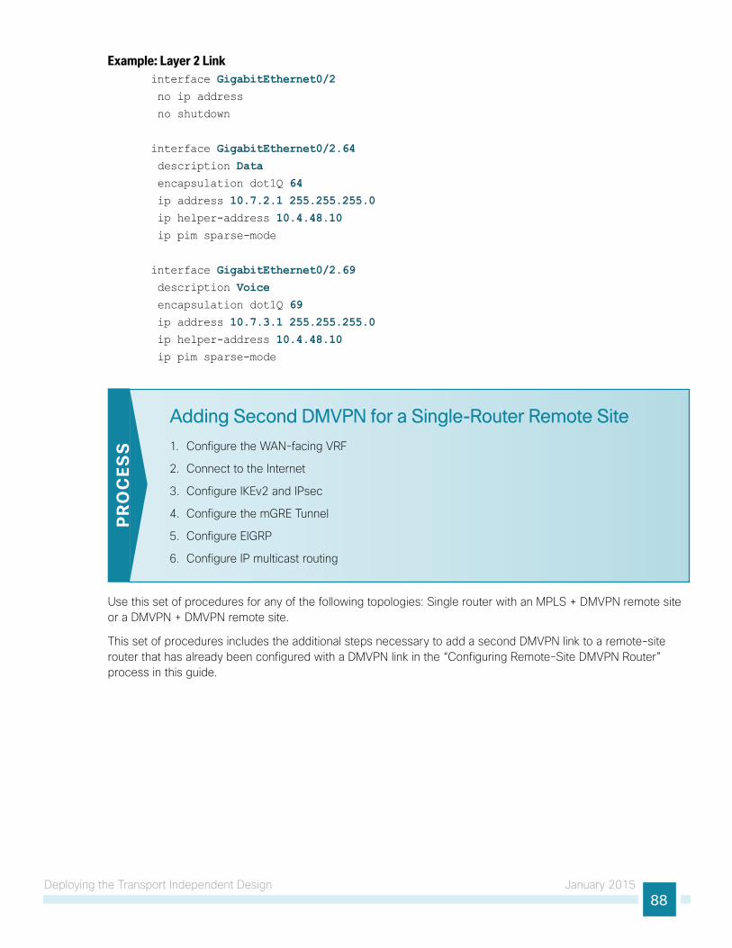
Deploying the Transport Independent Design January 201588
Example: Layer 2 Linkinterface GigabitEthernet0/2 no ip address
no shutdown
interface GigabitEthernet0/2.64 description Data encapsulation dot1Q 64 ip address 10.7.2.1 255.255.255.0 ip helper-address 10.4.48.10 ip pim sparse-mode
interface GigabitEthernet0/2.69 description Voice encapsulation dot1Q 69 ip address 10.7.3.1 255.255.255.0 ip helper-address 10.4.48.10 ip pim sparse-mode
Adding Second DMVPN for a Single-Router Remote Site
1. Configure the WAN-facing VRF
2. Connect to the Internet
3. Configure IKEv2 and IPsec
4. Configure the mGRE Tunnel
5. Configure EIGRP
6. Configure IP multicast routing
PR
OC
ESS
Use this set of procedures for any of the following topologies: Single router with an MPLS + DMVPN remote site or a DMVPN + DMVPN remote site.
This set of procedures includes the additional steps necessary to add a second DMVPN link to a remote-site router that has already been configured with a DMVPN link in the “Configuring Remote-Site DMVPN Router” process in this guide.

Deploying the Transport Independent Design January 201589
The following flowchart details how to add the second DMVPN to an existing remote-site router.
Figure 24 - Adding second DMVPN configuration flowchart
12
38
1. Configure the WAN-facing VRF2. Connect to the Internet3. Configure IKEv2 and IPSec4. Configure mGRE Tunnel5. Configure EIGRP6. Configure IP Multicast Routing
Procedures for Adding LTE Fallback DMVPN for a Single Router Remote Site
Procedures for Adding a Second DMVPN for a Single Router
Remote Site
YES
NO 1. Install LTE EHWIC into ISR2. Configure Chat Script3. Configure the WAN-facing VRF4. Connect to the Cellular Provider5. Configure the Dialer Watch List6. Configure VRF-specific Default Routing7. Configure IKEv2 and IPsec8. Configure the mGRE Tunnel9. Configure EIGRP10. Configure IP Multicast Routing11. Enable the Cellular Interface12. Control Usage of LTE Fallback Tunnel
C f f
12
Site Complete
YES
NO 1 I
Add LTEFallback?
Configure 2nd DMVPNfor a Single Router Remote Site

Deploying the Transport Independent Design January 201590
Procedure 1 Configure the WAN-facing VRF
You create a WAN-facing VRF in order to support FVRF for DMVPN. The VRF name is arbitrary, but it is useful to select a name that describes the VRF. The VRF must be enabled for IPv4.
Table 31 - VRF assignments
IWAN Design Model Primary WAN VRF Secondary WAN VRF
Hybrid IWAN-TRANSPORT-1 IWAN-TRANSPORT-2
Dual Internet IWAN-TRANSPORT-3 IWAN-TRANSPORT-4
This design uses VRF Lite, so the selection is only locally significant to the device. It is a best practice to use the same VRF/RD combination across multiple devices when using VRFs in a similar manner. However, this convention is not strictly required.
Step 1: Configure the secondary WAN VRF.
Example: Secondary WAN in the hybrid design modelvrf definition IWAN-TRANSPORT-2 address-family ipv4
Procedure 2 Connect to the Internet
The remote sites that are using DMVPN can use either static or dynamically assigned IP addresses. Cisco tested the design with DHCP assigned external addresses for Internet connections, which also provides a dynamically configured default route.
The DMVPN spoke router connects directly to the Internet without a separate firewall. This connection is secured in two ways. Because the Internet interface is in a separate VRF, no traffic can access the global VRF except traffic sourced through the DMVPN tunnel. This design provides implicit security. Additionally, an IP access list permits only the traffic required for an encrypted tunnel, as well as DHCP and various ICMP protocols for troubleshooting.
Step 1: Enable the interface, select VRF and enable DHCP.
The DMVPN design uses FVRF, so you must place this interface into the VRF configured in the previous procedure.
interface GigabitEthernet0/1 ip vrf forwarding IWAN-TRANSPORT-2 ip address dhcp
no cdp enable
no shutdown

Deploying the Transport Independent Design January 201591
Step 2: Configure and apply the access list.
The IP access list must permit the protocols specified in the following table. The access list is applied inbound on the WAN interface, so filtering is done on traffic destined to the router.
Table 32 - Required DMVPN protocols
Name Protocol Usage
non500-isakmp UDP 4500 IPsec via NAT-T
isakmp UDP 500 ISAKMP
esp IP 50 IPsec
bootpc UDP 68 DHCP
Exampleinterface GigabitEthernet0/1 ip access-group ACL-INET-PUBLIC in
ip access-list extended ACL-INET-PUBLIC permit udp any any eq non500-isakmp
permit udp any any eq isakmp
permit esp any any
permit udp any any eq bootpc
The additional protocols listed in the following table may assist in troubleshooting, but are not explicitly required to allow DMVPN to function properly.
Table 33 - Optional protocols: DMVPN spoke router
Name Protocol Usage
icmp echo ICMP Type 0, Code 0 Allow remote pings
icmp echo-reply ICMP Type 8, Code 0 Allow ping replies (from your requests)
icmp ttl-exceeded ICMP Type 11, Code 0 Allow traceroute replies (from your requests)
icmp port-unreachable ICMP Type 3, Code 3 Allow traceroute replies (from your requests)
UDP high ports UDP > 1023, TTL=1 Allow remote traceroute
IOS CA Port 80 172.16.140.110 on TCP / 80 Allow IOS CA to communicate with router during enrollment
The additional optional entries for an access list to support ping are as follows:
permit icmp any any echo
permit icmp any any echo-reply
The additional optional entries for an access list to support traceroute are as follows:
permit icmp any any ttl-exceeded ! for traceroute (sourced)
permit icmp any any port-unreachable ! for traceroute (sourced)
permit udp any any gt 1023 ttl eq 1 ! for traceroute (destination)
The additional optional entry for an access list to support IOS CA at the Internet DMZ address 172.16.140.11 on source port 80 is as follows:
permit tcp host 172.16.140.110 eq www any
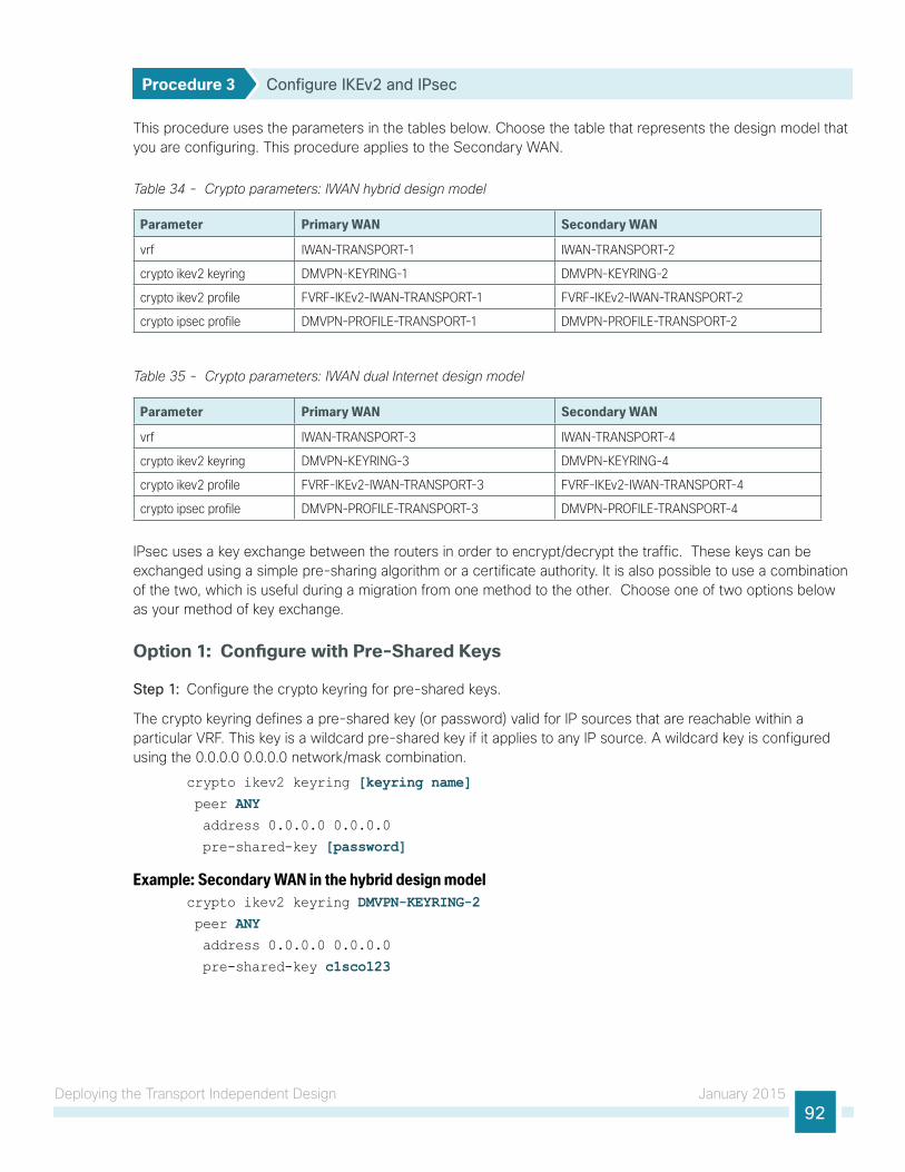
Deploying the Transport Independent Design January 201592
Procedure 3 Configure IKEv2 and IPsec
This procedure uses the parameters in the tables below. Choose the table that represents the design model that you are configuring. This procedure applies to the Secondary WAN.
Table 34 - Crypto parameters: IWAN hybrid design model
Parameter Primary WAN Secondary WAN
vrf IWAN-TRANSPORT-1 IWAN-TRANSPORT-2
crypto ikev2 keyring DMVPN-KEYRING-1 DMVPN-KEYRING-2
crypto ikev2 profile FVRF-IKEv2-IWAN-TRANSPORT-1 FVRF-IKEv2-IWAN-TRANSPORT-2
crypto ipsec profile DMVPN-PROFILE-TRANSPORT-1 DMVPN-PROFILE-TRANSPORT-2
Table 35 - Crypto parameters: IWAN dual Internet design model
Parameter Primary WAN Secondary WAN
vrf IWAN-TRANSPORT-3 IWAN-TRANSPORT-4
crypto ikev2 keyring DMVPN-KEYRING-3 DMVPN-KEYRING-4
crypto ikev2 profile FVRF-IKEv2-IWAN-TRANSPORT-3 FVRF-IKEv2-IWAN-TRANSPORT-4
crypto ipsec profile DMVPN-PROFILE-TRANSPORT-3 DMVPN-PROFILE-TRANSPORT-4
IPsec uses a key exchange between the routers in order to encrypt/decrypt the traffic. These keys can be exchanged using a simple pre-sharing algorithm or a certificate authority. It is also possible to use a combination of the two, which is useful during a migration from one method to the other. Choose one of two options below as your method of key exchange.
Option 1: Configure with Pre-Shared Keys
Step 1: Configure the crypto keyring for pre-shared keys.
The crypto keyring defines a pre-shared key (or password) valid for IP sources that are reachable within a particular VRF. This key is a wildcard pre-shared key if it applies to any IP source. A wildcard key is configured using the 0.0.0.0 0.0.0.0 network/mask combination.
crypto ikev2 keyring [keyring name] peer ANY address 0.0.0.0 0.0.0.0 pre-shared-key [password]
Example: Secondary WAN in the hybrid design modelcrypto ikev2 keyring DMVPN-KEYRING-2 peer ANY address 0.0.0.0 0.0.0.0 pre-shared-key c1sco123

Deploying the Transport Independent Design January 201593
Step 2: Configure the IKEv2 profile.
The default IKEv2 proposal is used, which includes the following:
• Encryption with AES cipher with a 256-bit key
• Integrity with SHA with 512-bit digest
• Pseudo-random function with SHA with 512-bit digest
• Diffie-Hellman group: 5
RS11-2921# show crypto ikev2 proposalIKEv2 proposal: default
Encryption: AES-CBC-256 AES-CBC-192 AES-CBC-128
Integrity : SHA512 SHA384 SHA256 SHA96 MD596
PRF : SHA512 SHA384 SHA256 SHA1 MD5
DH Group : DH_GROUP_1536_MODP/Group 5 DH_GROUP_1024_MODP/Group 2
The IKEv2 profile creates an association between an identity address, a VRF, and a crypto keyring. A wildcard address within a VRF is referenced with 0.0.0.0. The profile also defines what method of key sharing will be used on this router with authentication local and what methods will be accepted from remote locations with authentication remote. The pre-share keyword is used with the keyring defined above.
crypto ikev2 profile [profile name] match fvrf [vrf name] match identity remote address [IP address] authentication remote pre-share
authentication local pre-share
keyring local [keyring name]
Example: Secondary WAN in the hybrid design modelcrypto ikev2 profile FVRF-IKEv2-IWAN-TRANSPORT-2 match fvrf IWAN-TRANSPORT-2 match identity remote address 0.0.0.0 authentication remote pre-share
authentication local pre-share
keyring local DMVPN-KEYRING-2
Step 3: Configure the IPsec profile.
The IPsec profile creates an association between an IKEv2 profile and an IPsec transform-set.
crypto ipsec profile [profile name] set transform-set [transform set] set ikev2-profile [ikev2 profile name]
Example: Secondary WAN in the hybrid design modelcrypto ipsec profile DMVPN-PROFILE-TRANSPORT-2 set transform-set AES256/SHA/TRANSPORT set ikev2-profile FVRF-IKEv2-IWAN-TRANSPORT-2
Step 4: Proceed to Procedure 4, “Configure the mGRE Tunnel.”

Deploying the Transport Independent Design January 201594
Option 2: Configure with a certificate authorityThe crypto pki trustpoint is the method of specifying the parameters associated with a CA. This router has already authenticated to the CA and enrolled in order to obtain its identity certificate in a previous procedure.
Step 1: Configure the IKEv2 profile.
The default IKEv2 proposal is used, which includes the following:
• Encryption with AES cipher with a 256-bit key
• Integrity with SHA with 512-bit digest
• Pseudo-random function with SHA with 512-bit digest
• Diffie-Hellman group: 5
RS11-2921# show crypto ikev2 proposalIKEv2 proposal: default
Encryption: AES-CBC-256 AES-CBC-192 AES-CBC-128
Integrity : SHA512 SHA384 SHA256 SHA96 MD596
PRF : SHA512 SHA384 SHA256 SHA1 MD5
DH Group : DH_GROUP_1536_MODP/Group 5 DH_GROUP_1024_MODP/Group 2
The IKEv2 profile creates an association between an identity address, a VRF, and a crypto keyring. A wildcard address within a VRF is referenced with 0.0.0.0. The profile also defines what method of key sharing will be used on this router with authentication local and what methods will be accepted from remote locations with authentication remote. The rsa-sig keyword is used when certificates contain the encryption key.
crypto ikev2 profile [profile name] match fvrf [vrf name] match identity remote address [IP address] authentication remote rsa-sig
authentication local rsa-sig
pki trustpoint [trustpoint name]
Example: RS11-2921This example is from a secondary WAN in the hybrid design model.
crypto ikev2 profile FVRF-IKEv2-IWAN-TRANSPORT-2 match fvrf IWAN-TRANSPORT-2 match identity remote address 0.0.0.0 authentication remote rsa-sig
authentication local rsa-sig
pki trustpoint IWAN-CA
Step 2: Configure the IPSec profile.
The IPsec profile creates an association between an IKEv2 profile and an IPsec transform-set.
crypto ipsec profile [profile name] set transform-set [transform set] set ikev2-profile [ikev2 profile name]

Deploying the Transport Independent Design January 201595
Example: RS11-2921This example is from a secondary WAN in the hybrid design model.
crypto ipsec profile DMVPN-PROFILE-TRANSPORT-2 set transform-set AES256/SHA/TRANSPORT set ikev2-profile FVRF-IKEv2-IWAN-TRANSPORT-2
Procedure 4 Configure the mGRE Tunnel
This procedure uses the parameters in the table below. Choose the rows that represent the design model that you are configuring. This procedure applies to the secondary WAN.
Table 36 - DMVPN tunnel parameters
Design Model Tunnel VRFTunnel Number Tunnel Network
NHRP network ID / Tunnel Key
Hybrid—Primary WAN IWAN-TRANSPORT-1 10 10.6.34.0/23 101
Hybrid—Secondary WAN IWAN-TRANSPORT-2 11 10.6.36.0/23 102
Dual Internet—Primary WAN IWAN-TRANSPORT-3 20 10.6.38.0/23 201
Dual Internet—Secondary WAN IWAN-TRANSPORT-4 21 10.6.40.0/23 202
Step 1: Configure the basic interface settings.
The tunnel number is arbitrary, but it is best to begin tunnel numbering at 10 or above, because other features deployed in this design may also require tunnels and they may select lower numbers by default.
The bandwidth setting must be set to match the bandwidth of the respective transport, which corresponds to the actual interface speed. Or, if you are using a subrate service, use the policed rate from the carrier. QoS and PfR require the correct bandwidth setting in order to operate properly.
Configure the ip mtu to 1400 and the ip tcp adjust-mss to 1360. There is a 40 byte difference, which corresponds to the combined IP and TCP header length.
The tunnel interface throughput delay setting should be set to influence the routing protocol path preference. Set the primary WAN path to 10000 usec and the secondary WAN path to 20000 usec to prefer one over the other. The delay command is entered in 10 usec units.
interface Tunnel11 bandwidth 200000 ip address 10.6.36.11 255.255.254.0 no ip redirects
ip mtu 1400
ip tcp adjust-mss 1360
delay 2000
Step 2: Configure the tunnel.
DMVPN uses mGRE tunnels. This type of tunnel requires a source interface only. Use the same source interface that you use to connect to the Internet. Set the tunnel vrf command should be set to the VRF defined previously for FVRF.

Deploying the Transport Independent Design January 201596
Enabling encryption on this interface requires the application of the IPsec profile configured in the previous procedure.
interface Tunnel11 tunnel source GigabitEthernet0/1 tunnel mode gre multipoint
tunnel key 102 tunnel vrf IWAN-TRANSPORT-2 tunnel protection ipsec profile DMVPN-PROFILE-TRANSPORT-2
Step 3: Configure NHRP.
The DMVPN hub router is the NHRP server for all of the spokes. NHRP is used by remote routers to determine the tunnel destinations for peers attached to the mGRE tunnel.
The spoke router requires several additional configuration statements to define the NHRP server (NHS) and NHRP map statements for the DMVPN hub router mGRE tunnel IP address. EIGRP (configured in the following Procedure 5) relies on a multicast transport. Spoke routers require the NHRP static multicast mapping.
The value used for the NHS is the mGRE tunnel address for the DMVPN hub router. The map entries must be set to the outside NAT value of the DMVPN hub, as configured on the Cisco ASA 5500. This design uses the values shown in the following tables.
Table 37 - DMVPN tunnel NHRP parameters: IWAN hybrid design model
Transport 1 Transport 2
VRF IWAN-TRANSPORT-1 IWAN-TRANSPORT-2
DMVPN hub public address (actual) 192.168.6.1 192.168.146.10
DMVPN hub public address (externally routable after NAT)
n/a (MPLS) 172.16.140.1
DMVPN hub tunnel IP address (NHS) 10.6.34.1 10.6.36.1
Tunnel number 10 11
NHRP network ID 101 102
Table 38 - DMVPN tunnel NHRP parameters: IWAN dual Internet design model
Transport 3 Transport 4
VRF IWAN-TRANSPORT-3 IWAN-TRANSPORT-4
DMVPN hub public address (actual) 192.168.146.20 192.168.146.21
DMVPN hub public address (externally routable after NAT)
172.16.140.11 172.17.140.11
DMVPN hub tunnel IP address (NHS) 10.6.38.1 10.6.40.1
Tunnel number 20 21
NHRP network ID 201 202
NHRP requires all devices within a DMVPN cloud to use the same network ID and authentication key. The NHRP cache holdtime should be configured to 600 seconds.

Deploying the Transport Independent Design January 201597
This design supports DMVPN spoke routers that receive their external IP addresses through DHCP. It is possible for these routers to acquire different IP addresses after a reload. When the router attempts to register with the NHRP server, it may appear as a duplicate to an entry already in the cache and be rejected. The registration no-unique option allows you to overwrite existing cache entries. This feature is only required on NHRP clients (DMVPN spoke routers). The if-state nhrp option ties the tunnel line-protocol state to the reachability of the NHRP NHS, and if the NHS is unreachable the tunnel line-protocol state changes to down. This feature is used in conjunction with EOT.
interface Tunnel11 ip nhrp authentication cisco123 ip nhrp network-id 102 ip nhrp holdtime 600 ip nhrp nhs 10.6.36.1 nbma 172.16.140.1 multicast ip nhrp registration no-unique
ip nhrp shortcut
if-state nhrp
Procedure 5 Configure EIGRP
A single EIGRP process runs on the DMVPN spoke router, which has already been enabled during the first DMVPN tunnel’s configuration. All interfaces on the router are EIGRP interfaces, but only the DMVPN tunnel interfaces are non-passive. The network range must include all interface IP addresses either in a single network statement or in multiple network statements.
Step 1: Add the network range for the secondary DMVPN tunnel and configure as non-passive.
router eigrp IWAN-EIGRP address-family ipv4 unicast autonomous-system 400 af-interface Tunnel11 no passive-interface
exit-af-interface
network 10.6.36.0 0.0.1.255exit-address-family
Step 2: Configure EIGRP values for the mGRE tunnel interface.
The EIGRP hello interval is increased to 20 seconds and the EIGRP hold time is increased to 60 seconds in order to accommodate up to 2000 remote sites on a single DMVPN cloud. Increasing the EIGRP timers also slows down the routing convergence to improve network stability and the IWAN design allows PfR to initiate the fast failover, so changing the timers is recommended for all IWAN deployments.
router eigrp IWAN-EIGRP address-family ipv4 unicast autonomous-system 400 af-interface Tunnel11 hello-interval 20 hold-time 60 exit-af-interface
exit-address-family

Deploying the Transport Independent Design January 201598
Step 3: Configure EIGRP neighbor authentication. Neighbor authentication enables the secure establishment of peering adjacencies and exchange route tables over the DMVPN tunnel interface.
key chain WAN-KEY key 1
key-string c1sco123
router eigrp IWAN-EIGRP address-family ipv4 unicast autonomous-system 400 af-interface Tunnel11 authentication mode md5
authentication key-chain WAN-KEY exit-af-interface
exit-address-family
Step 4: Configure EIGRP route summarization.
The remote-site LAN networks must be advertised. The IP assignment for the remote sites was designed so that all of the networks in use can be summarized within a single aggregate route. The summary address as configured below suppresses the more specific routes. If any network within the summary is present in the route table, the summary is advertised to the DMVPN hub, which offers a measure of resiliency. If the various LAN networks cannot be summarized, EIGRP continues to advertise the specific routes.
router eigrp IWAN-EIGRP address-family ipv4 unicast autonomous-system 400 af-interface Tunnel11 summary-address [summary network] [summary mask] exit-af-interface
exit-address-family
Procedure 6 Configure IP multicast routing
This procedure includes additional steps for configuring IP Multicast for a DMVPN tunnel on a router with IP Multicast already enabled.
Step 1: Configure PIM on the DMVPN tunnel interface.
Enable IP PIM sparse mode on the DMVPN tunnel interface.
interface Tunnel11 ip pim sparse-mode
Step 2: Enable PIM NBMA mode for the DMVPN tunnel.
Spoke-to-spoke DMVPN networks present a unique challenge because the spokes cannot directly exchange information with one another, even though they are on the same logical network. This inability to directly exchange information can also cause problems when running IP Multicast.
To resolve the NBMA issue, you need to implement a method where each remote PIM neighbor has its join messages tracked separately. A router in PIM NBMA mode treats each remote PIM neighbor as if it were connected to the router through a point-to-point link.
interface Tunnel11 ip pim nbma-mode

Deploying the Transport Independent Design January 201599
Step 3: Configure the DR priority for the DMVPN spoke router.
Proper multicast operation across a DMVPN cloud requires that the hub router assumes the role of PIM designated router (DR). Spoke routers should never become the DR. You can prevent that by setting the DR priority to 0 for the spokes.
interface Tunnel11 ip pim dr-priority 0
Adding LTE fallback DMVPN for a single-router remote site
1. Install LTE EHWIC into ISR
2. Configure chat script
3. Configure the WAN-facing VRF
4. Connect to the cellular provider
5. Configure the dialer watch list
6. Configure VRF-specific default routing
7. Configure IKEv2 and IPsec
8. Configure the mGRE Tunnel
9. Configure EIGRP
10. Configure IP multicast routing
11. Enable the cellular interface
12. Control usage of LTE fallback tunnel
PR
OC
ESS
This set of procedures includes the additional steps necessary to add a third fallback DMVPN link to a remote-site router that has already been configured primary and secondary DMVPN links by using the following processes in this guide:
• “Configuring Remote-Site DMVPN Router”
• “Adding Second DMVPN for a Single-Router Remote Site”
This section includes only the additional procedures for adding the LTE fallback DMVPN to the running remote-site router.
This section is specific to cellular LTE devices used to test this document. There are other Cisco products that share common configuration with the devices mentioned that may have different packages (Cisco Enhanced High-Speed WAN Interface Card [EHWIC] vs. router) and different carriers. You must get a data service account from your service provider. You should receive a SIM card that you install on the LTE EHWIC, no matter the carrier.
There are vendor specific variations of 4G/LTE HWICs, some with geographically specific firmware. The table below shows the version of the 4G/LTE card validated in this guide and the version of firmware tested. Additional specific geographic and carrier information for the various Cisco cellular WAN access interfaces can be found online at: http://www.cisco.com/c/en/us/products/routers/networking_solutions_products_genericcontent0900aecd80601f7e.html
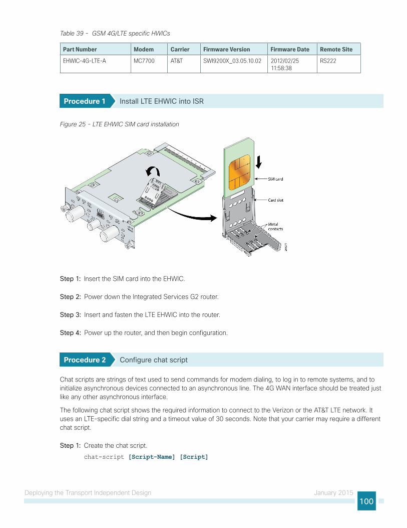
Deploying the Transport Independent Design January 2015100
Table 39 - GSM 4G/LTE specific HWICs
Part Number Modem Carrier Firmware Version Firmware Date Remote Site
EHWIC-4G-LTE-A MC7700 AT&T SWI9200X_03.05.10.02 2012/02/25 11:58:38
RS222
Procedure 1 Install LTE EHWIC into ISR
Figure 25 - LTE EHWIC SIM card installation
Step 1: Insert the SIM card into the EHWIC.
Step 2: Power down the Integrated Services G2 router.
Step 3: Insert and fasten the LTE EHWIC into the router.
Step 4: Power up the router, and then begin configuration.
Procedure 2 Configure chat script
Chat scripts are strings of text used to send commands for modem dialing, to log in to remote systems, and to initialize asynchronous devices connected to an asynchronous line. The 4G WAN interface should be treated just like any other asynchronous interface.
The following chat script shows the required information to connect to the Verizon or the AT&T LTE network. It uses an LTE-specific dial string and a timeout value of 30 seconds. Note that your carrier may require a different chat script.
Step 1: Create the chat script.
chat-script [Script-Name] [Script]

Deploying the Transport Independent Design January 2015101
Examplechat-script LTE "" "AT!CALL1" TIMEOUT 30 "OK"
Step 2: Apply the chat script to the asynchronous line.
line [Cellular-Interface-Number] script dialer [Script-Name]
ExampleFor the interface cellular0/1/0, the matching line would be as follows.
line 0/1/0 script dialer LTE
Procedure 3 Configure the WAN-facing VRF
You create a WAN-facing VRF in order to support FVRF for DMVPN. The VRF name is arbitrary, but it is useful to select a name that describes the VRF. The VRF must be enabled for IPv4.
Table 40 - VRF assignments
IWAN Design Model Primary WAN VRF Secondary WAN VRF LTE Fallback VRF
Hybrid IWAN-TRANSPORT-1 IWAN-TRANSPORT-2 IWAN-TRANSPORT-3
Dual Internet IWAN-TRANSPORT-3 IWAN-TRANSPORT-4 IWAN-TRANSPORT-1
This design uses VRF Lite, so the selection is only locally significant to the device. It is a best practice to use the same VRF/RD combination across multiple devices when using VRFs in a similar manner. However, this convention is not strictly required.
Step 1: Configure the LTE fallback VRF.
Example: Transport 3 in the IWAN hybrid design modelvrf definition IWAN-TRANSPORT-3 address-family ipv4
Procedure 4 Connect to the cellular provider
You add the cellular interface to a dialer watch group and to the VRF. You set the bandwidth value to match the minimum uplink speed of the chosen technology, as shown in the following table. Configure the interface as administratively down until the rest of the configuration steps are complete.
Table 41 - 4G encapsulation and bandwidth parameters
Cellular keyword Encapsulation
Cellular Script Name (Created Previously) Downlink speed (Kbps) Uplink speed (Kbps)
LTE Direct IP (SLIP) LTE 8000 to 12,000 (range) 2000 to 5000 (range)

Deploying the Transport Independent Design January 2015102
LTE cellular interfaces use Direct IP encapsulation. When configuring Direct IP encapsulation, use the serial line Internet protocol (SLIP) keyword.
Tech Tip
Step 1: Configure the cellular interface.
interface Cellular [Interface-Number] bandwidth [bandwidth (Kbps)] vrf forwarding IWAN-TRANSPORT-3 ip address negotiated
no ip unreachables
ip virtual-reassembly in
encapsulation [encapsulation type] dialer in-band
dialer idle-timeout 0
dialer string [Chat Script Name] dialer watch-group 1 no peer default ip address
async mode interactive
shutdown
Example: LTE Bandwidth and Encapsulationinterface Cellular0/1/0 bandwidth 2000 ip vrf forwarding IWAN-TRANSPORT-3 ip address negotiated
no ip unreachables
ip virtual-reassembly in
encapsulation slip dialer in-band
dialer idle-timeout 0
dialer string LTE dialer watch-group 1 no peer default ip address
async mode interactive
shutdown

Deploying the Transport Independent Design January 2015103
Step 2: Configure and apply the access list.
The IP access list must permit the protocols specified in the following table. The access list is applied inbound on the WAN interface, so filtering is done on traffic destined to the router.
Table 42 - Required DMVPN protocols
Name Protocol Usage
non500-isakmp UDP 4500 IPsec via NAT-T
isakmp UDP 500 ISAKMP
esp IP 50 IPsec
interface Cellular0/1/0 ip access-group ACL-INET-PUBLIC-4G in
ip access-list extended ACL-INET-PUBLIC-4G permit udp any any eq non500-isakmp
permit udp any any eq isakmp
permit esp any any
permit udp any any eq bootpc
The additional protocols listed in the following table may assist in troubleshooting but are not explicitly required to allow DMVPN to function properly.
Table 43 - Optional protocols: DMVPN spoke router
Name Protocol Usage
icmp echo ICMP Type 0, Code 0 Allow remote pings
icmp echo-reply ICMP Type 8, Code 0 Allow ping replies (from your requests)
icmp ttl-exceeded ICMP Type 11, Code 0 Allow traceroute replies (from your requests)
icmp port-unreachable ICMP Type 3, Code 3 Allow traceroute replies (from your requests)
UDP high ports UDP > 1023, TTL=1 Allow remote traceroute
IOS CA Port 80 172.16.140.110 on TCP / 80 Allow IOS CA to communicate with router during enrollment
The additional optional entries for an access list to support ping are as follows:
permit icmp any any echo
permit icmp any any echo-reply
The additional optional entries for an access list to support traceroute are as follows:
permit icmp any any ttl-exceeded ! for traceroute (sourced)
permit icmp any any port-unreachable ! for traceroute (sourced)
permit udp any any gt 1023 ttl eq 1 ! for traceroute (destination)
The additional optional entry for an access list to support IOS CA at the Internet DMZ address 172.16.140.11 on source port 80 is as follows:
permit tcp host 172.16.140.110 eq www any

Deploying the Transport Independent Design January 2015104
Procedure 5 Configure the dialer watch list
The dialer watch-list is a construct that allows the activation of the dialer script and associated cellular interface when the specified route no longer exists in the routing table. In this procedure, the dialer-watch list activates the cellular interface when the specified phantom route is missing from the routing table.
This design uses the IANA-specified loopback address of 127.0.0.255, which should never appear in the routing table under normal circumstances. The absence of this route in the routing table causes the cellular interface to become active and stay active until the interface is brought down.
Step 1: Assign a phantom route to the dialer watch-list. Use the same value as the dialer watch-group in the previous procedure.
dialer watch-list 1 ip 127.0.0.255 255.255.255.255 dialer watch-list 1 delay route-check initial 60dialer watch-list 1 delay connect 1
Procedure 6 Configure VRF-specific default routing
The remote sites using 3G or 4G DMVPN use negotiated IP addresses for the cellular interfaces. Unlike DHCP, the negotiation does not automatically set a default route. This step must be completed manually.
Step 1: Configure a VRF-specific default route for the cellular interface.
ip route vrf IWAN-TRANSPORT-3 0.0.0.0 0.0.0.0 Cellular0/1/0
Procedure 7 Configure IKEv2 and IPsec
This procedure uses the parameters in the following table. Choose the column that represents the design model that you are configuring. This procedure applies to the LTE Fallback DMVPN using either the IWAN hybrid design model or the IWAN dual Internet design model.
Table 44 - Crypto parameters: LTE fallback DMVPN
Parameter IWAN Hybrid Design Model IWAN Dual Internet Design Model
vrf IWAN-TRANSPORT-3 IWAN-TRANSPORT-1
crypto ikev2 keyring DMVPN-KEYRING-3 DMVPN-KEYRING-1
crypto ikev2 profile FVRF-IKEv2-IWAN-TRANSPORT-3 FVRF-IKEv2-IWAN-TRANSPORT-1
crypto ipsec profile DMVPN-PROFILE-TRANSPORT-3 DMVPN-PROFILE-TRANSPORT-1
IPsec uses a key exchange between the routers in order to encrypt/decrypt the traffic. These keys can be exchanged using a simple pre-sharing algorithm or a certificate authority. It is also possible to use a combination of the two, which is useful during a migration from one method to the other. Choose one of two options below as your method of key exchange.

Deploying the Transport Independent Design January 2015105
Option 1: Configure with Pre-Shared Keys
Step 1: Configure the crypto keyring for pre-shared keys.
The crypto keyring defines a pre-shared key (or password) valid for IP sources that are reachable within a particular VRF. This key is a wildcard pre-shared key if it applies to any IP source. A wildcard key is configured using the 0.0.0.0 0.0.0.0 network/mask combination.
crypto ikev2 keyring [keyring name] peer ANY address 0.0.0.0 0.0.0.0 pre-shared-key [password]
Example: LTE remote site router in the IWAN hybrid design modelcrypto ikev2 keyring DMVPN-KEYRING-3 peer ANY address 0.0.0.0 0.0.0.0 pre-shared-key c1sco123
Step 2: Configure the IKEv2 profile.
The default IKEv2 proposal is used, which includes the following:
• Encryption with AES cipher with a 256-bit key
• Integrity with SHA with 512-bit digest
• Pseudo-random function with SHA with 512-bit digest
• Diffie-Hellman group: 5
RS51-2921# show crypto ikev2 proposalIKEv2 proposal: default
Encryption: AES-CBC-256 AES-CBC-192 AES-CBC-128
Integrity : SHA512 SHA384 SHA256 SHA96 MD596
PRF : SHA512 SHA384 SHA256 SHA1 MD5
DH Group : DH_GROUP_1536_MODP/Group 5 DH_GROUP_1024_MODP/Group 2
The IKEv2 profile creates an association between an identity address, a VRF, and a crypto keyring. A wildcard address within a VRF is referenced with 0.0.0.0. The profile also defines what method of key sharing will be used on this router with authentication local and what methods will be accepted from remote locations with authentication remote. The pre-share keyword is used with the keyring defined above.
crypto ikev2 profile [profile name] match fvrf [vrf name] match identity remote address [IP address] authentication remote pre-share
authentication local pre-share
keyring local [keyring name] crypto ikev2 dpd [interval in seconds] [retry interval] on-demand
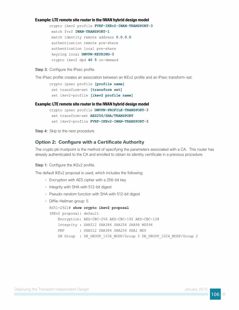
Deploying the Transport Independent Design January 2015106
Example: LTE remote site router in the IWAN hybrid design modelcrypto ikev2 profile FVRF-IKEv2-IWAN-TRANSPORT-3 match fvrf IWAN-TRANSPORT-1 match identity remote address 0.0.0.0 authentication remote pre-share
authentication local pre-share
keyring local DMVPN-KEYRING-3 crypto ikev2 dpd 40 5 on-demand
Step 3: Configure the IPsec profile.
The IPsec profile creates an association between an IKEv2 profile and an IPsec transform-set.
crypto ipsec profile [profile name] set transform-set [transform set] set ikev2-profile [ikev2 profile name]
Example: LTE remote site router in the IWAN hybrid design modelcrypto ipsec profile DMVPN-PROFILE-TRANSPORT-3 set transform-set AES256/SHA/TRANSPORT set ikev2-profile FVRF-IKEv2-IWAN-TRANSPORT-3
Step 4: Skip to the next procedure.
Option 2: Configure with a Certificate AuthorityThe crypto pki trustpoint is the method of specifying the parameters associated with a CA. This router has already authenticated to the CA and enrolled to obtain its identity certificate in a previous procedure.
Step 1: Configure the IKEv2 profile.
The default IKEv2 proposal is used, which includes the following:
• Encryption with AES cipher with a 256-bit key
• Integrity with SHA with 512-bit digest
• Pseudo-random function with SHA with 512-bit digest
• Diffie-Hellman group: 5
RS51-2921# show crypto ikev2 proposalIKEv2 proposal: default
Encryption: AES-CBC-256 AES-CBC-192 AES-CBC-128
Integrity : SHA512 SHA384 SHA256 SHA96 MD596
PRF : SHA512 SHA384 SHA256 SHA1 MD5
DH Group : DH_GROUP_1536_MODP/Group 5 DH_GROUP_1024_MODP/Group 2

Deploying the Transport Independent Design January 2015107
The IKEv2 profile creates an association between an identity address, a VRF, and a crypto keyring. A wildcard address within a VRF is referenced with 0.0.0.0. The profile also defines what method of key sharing will be used on this router with authentication local and what methods will be accepted from remote locations with authentication remote. The rsa-sig keyword is used when certificates contain the encryption key.
crypto ikev2 profile [profile name] match fvrf [vrf name] match identity remote address [IP address] authentication remote rsa-sig
authentication local rsa-sig
pki trustpoint [trustpoint name]
Example: RS51-2921This example is from an LTE remote site router in the hybrid design model.
crypto ikev2 profile FVRF-IKEv2-IWAN-TRANSPORT-3 match fvrf IWAN-TRANSPORT-3 match identity remote address 0.0.0.0 authentication remote rsa-sig
authentication local rsa-sig
pki trustpoint IWAN-CA
Step 2: Configure the IPSec profile.
The IPsec profile creates an association between an IKEv2 profile and an IPsec transform-set.
crypto ipsec profile [profile name] set transform-set [transform set] set ikev2-profile [ikev2 profile name]
Example: RS51-2921This example is from an LTE remote site router in the hybrid design model.
crypto ipsec profile DMVPN-PROFILE-TRANSPORT-3 set transform-set AES256/SHA/TRANSPORT set ikev2-profile FVRF-IKEv2-IWAN-TRANSPORT-3
Procedure 8 Configure the mGRE Tunnel
This procedure uses the parameters in the table below. Choose the rows that represent the design model that you are configuring.
Table 45 - LTE fallback DMVPN tunnel parameters
Design Model Tunnel VRFTunnel Number Tunnel Network
NHRP network ID / Tunnel Key
Hybrid IWAN-TRANSPORT-3 20 10.6.38.0/23 201
Dual Internet IWAN-TRANSPORT-1 10 10.6.34.0/23 101

Deploying the Transport Independent Design January 2015108
Step 1: Configure basic interface settings.
The tunnel number is arbitrary, but it is best to begin tunnel numbering at 10 or above, because other features deployed in this design may also require tunnels and they may select lower numbers by default.
The bandwidth setting must be set to match the bandwidth of the respective transport which corresponds to the actual interface speed. Or, if you are using a subrate service, use the policed rate from the carrier. QoS and PfR require the correct bandwidth setting to operate properly.
Configure the ip mtu to 1400 and the ip tcp adjust-mss to 1360. There is a 40 byte difference, which corresponds to the combined IP and TCP header length.
The tunnel interface throughput delay setting is not needed because this is a tertiary path which will only be used when the other two paths are not available.
interface Tunnel20 bandwidth 8000 ip address 10.6.38.51 no ip redirects
ip mtu 1400
ip tcp adjust-mss 1360
Step 2: Configure the tunnel.
DMVPN uses mGRE tunnels. This type of tunnel requires a source interface only. Use the same source interface that you use to connect to the Internet. Set the tunnel vrf command should be set to the VRF defined previously for FVRF.
Enabling encryption on this interface requires the application of the IPsec profile configured in the previous procedure.
interface Tunnel20 tunnel source Cellular0/1/0 tunnel mode gre multipoint
tunnel key 201 tunnel vrf IWAN-TRANSPORT-3 tunnel protection ipsec profile DMVPN-PROFILE-TRANSPORT-3
Step 3: Configure NHRP.
The DMVPN hub router is the NHRP server for all of the spokes. NHRP is used by remote routers to determine the tunnel destinations for peers attached to the mGRE tunnel.
The spoke router requires several additional configuration statements to define the NHRP server (NHS) and NHRP map statements for the DMVPN hub router mGRE tunnel IP address. EIGRP (configured in the following Procedure 5) relies on a multicast transport. Spoke routers require the NHRP static multicast mapping.

Deploying the Transport Independent Design January 2015109
The value used for the NHS is the mGRE tunnel address for the DMVPN hub router. The map entries must be set to the outside NAT value of the DMVPN hub, as configured on the Cisco ASA 5500. This design uses the values shown in Table 37 and Table 38.
Table 46 - DMVPN tunnel NHRP parameters: IWAN hybrid design model
LTE Fallback
VRF IWAN-TRANSPORT-3
DMVPN hub public address (actual) 192.168.146.20
DMVPN hub public address (externally routable after NAT) 172.16.140.11
DMVPN hub tunnel IP address (NHS) 10.6.38.1
Tunnel number 20
NHRP network ID 201
Table 47 - LTE fallback DMVPN tunnel NHRP parameters: IWAN dual Internet design model
LTE Fallback
VRF IWAN-TRANSPORT-1
DMVPN hub public address (actual) 192.168.146.10
DMVPN hub public address (externally routable after NAT) 172.16.140.1
DMVPN hub tunnel IP address (NHS) 10.6.34.1
Tunnel number 10
NHRP network ID 101
NHRP requires all devices within a DMVPN cloud to use the same network ID and authentication key. The NHRP cache holdtime should be configured to 600 seconds.
This design supports DMVPN spoke routers that receive their external IP addresses through DHCP. It is possible for these routers to acquire different IP addresses after a reload. When the router attempts to register with the NHRP server, it may appear as a duplicate to an entry already in the cache and be rejected. The registration no-unique option allows you to overwrite existing cache entries. This feature is only required on NHRP clients (DMVPN spoke routers). The if-state nhrp option ties the tunnel line-protocol state to the reachability of the NHRP NHS, and if the NHS is unreachable, the tunnel line-protocol state changes to down.
interface Tunnel20 ip nhrp authentication cisco123 ip nhrp network-id 201 ip nhrp holdtime 600 ip nhrp nhs 10.6.38.1 nbma 172.16.140.11 multicast ip nhrp registration no-unique
ip nhrp shortcut
if-state nhrp

Deploying the Transport Independent Design January 2015110
Procedure 9 Configure EIGRP
A single EIGRP process runs on the DMVPN spoke router, which has already been enabled during the configuration of the first DMVPN tunnel. All interfaces on the router are EIGRP interfaces, but only the DMVPN tunnel interfaces are non-passive. The network range must include all interface IP addresses either in a single network statement or in multiple network statements.
Step 1: Add the network range for the LTE Fallback DMVPN tunnel and configure as non-passive.
router eigrp IWAN-EIGRP address-family ipv4 unicast autonomous-system 400 af-interface Tunnel20 no passive-interface
exit-af-interface
network 10.6.38.0 0.0.1.255exit-address-family
Step 2: Configure EIGRP values for the mGRE tunnel interface.
The EIGRP hello interval is increased to 20 seconds and the EIGRP hold time is increased to 60 seconds in order to accommodate up to 2000 remote sites on a single DMVPN cloud. Increasing the EIGRP timers also slows down the routing convergence to improve network stability and the IWAN design allows PfR to initiate the fast failover, so changing the timers is recommended for all IWAN deployments.
router eigrp IWAN-EIGRP address-family ipv4 unicast autonomous-system 400 af-interface Tunnel20 hello-interval 20 hold-time 60 exit-af-interface
exit-address-family
Step 3: Configure EIGRP neighbor authentication. Neighbor authentication enables the secure establishment of peering adjacencies and exchange route tables over the DMVPN tunnel interface.
key chain WAN-KEY key 1
key-string c1sco123!
router eigrp IWAN-EIGRP address-family ipv4 unicast autonomous-system 400 af-interface Tunnel20 authentication mode md5
authentication key-chain WAN-KEY exit-af-interface
exit-address-family

Deploying the Transport Independent Design January 2015111
Step 4: Configure EIGRP route summarization.
The remote-site LAN networks must be advertised. The IP assignment for the remote sites was designed so that all of the networks in use can be summarized within a single aggregate route. The summary address as configured below suppresses the more specific routes. If any network within the summary is present in the route table, the summary is advertised to the DMVPN hub, which offers a measure of resiliency. If the various LAN networks cannot be summarized, EIGRP continues to advertise the specific routes.
router eigrp IWAN-EIGRP address-family ipv4 unicast autonomous-system 400 af-interface Tunnel20 summary-address [summary network] [summary mask] exit-af-interface
exit-address-family
Procedure 10 Configure IP multicast routing
This procedure includes additional steps for configuring IP Multicast for a DMVPN tunnel on a router with IP Multicast already enabled.
Step 1: Configure PIM on the DMVPN tunnel interface.
Enable IP PIM sparse mode on the DMVPN tunnel interface.
interface Tunnel20 ip pim sparse-mode
Step 2: Enable PIM NBMA mode for the DMVPN tunnel.
Spoke-to-spoke DMVPN networks present a unique challenge because the spokes cannot directly exchange information with one another, even though they are on the same logical network. This inability to directly exchange information can also cause problems when running IP Multicast.
To resolve the NBMA issue, you need to implement a method where each remote PIM neighbor has its join messages tracked separately. A router in PIM NBMA mode treats each remote PIM neighbor as if it were connected to the router through a point-to-point link.
interface Tunnel20 ip pim nbma-mode
Step 3: Configure the DR priority for the DMVPN spoke router.
Proper multicast operation across a DMVPN cloud requires that the hub router assumes the role of PIM DR. Spoke routers should never become the DR. You can prevent that by setting the DR priority to 0 for the spokes.
interface Tunnel20 ip pim dr-priority 0

Deploying the Transport Independent Design January 2015112
Procedure 11 Enable the cellular interface
The 4G/LTE portion of the router configuration is essentially complete.
Step 1: Enable the cellular interface to bring up the DMVPN tunnel.
interface Cellular0/1/0 no shutdown
Procedure 12 Control usage of LTE fallback tunnel
Many 4G/LTE service providers do not offer a mobile data plan with unlimited usage. More typically, you will need to select a usage-based plan with a bandwidth tier that aligns with the business requirements for the remote site. To minimize recurring costs of the 4G/LTE solution, it is a best practice to limit the use of the wireless WAN specifically to a backup-only path.
The remote-site router can use EOT to track the status of the DMVPN hub routers for the primary and secondary links. If both become unreachable, then the router can use the Embedded Event Manager (EEM) to dynamically enable the cellular interface.
Step 1: Configure EOT to track the interface state of primary and secondary tunnels.
This step links the status of each interface to a basic EOT object.
track 10 interface Tunnel10 line-protocoltrack 11 interface Tunnel11 line-protocol
Step 2: Configure composite object tracking.
A track list using Boolean OR is Up if either basic object is Up, and changes state to Down only when both basic objects are Down. This logic permits either the primary or secondary DMVPN tunnel to fail without enabling the LTE fallback tunnel. Both the primary and secondary tunnels must be down before the LTE fallback tunnel is enabled.
A short delay of 20 seconds is added when the primary or secondary tunnels are restored before shutting down the cellular interface.
track 20 list boolean or object 10 object 11 delay up 20

Deploying the Transport Independent Design January 2015113
Step 3: Configure EEM scripting to enable or disable the cellular interface.
An event-tracking EEM script monitors the state of an object and runs router Cisco IOS commands for that particular state. It is also a best practice to generate syslog messages that provide status information regarding EEM.
event manager applet [EEM script name] event track [object number] state [tracked object state] action [sequence 1] cli command "[command 1]" action [sequence 2] cli command "[command 2]" action [sequence 3] cli command "[command 3]" action [sequence …] cli command "[command …]" action [sequence N] syslog msg "[syslog message test]"
Example: EEM script to enable the cellular interface.event manager applet ACTIVATE-LTE event track 20 state down action 1 cli command "enable" action 2 cli command "configure terminal" action 3 cli command "interface cellular0/1/0" action 4 cli command "no shutdown" action 5 cli command "end" action 99 syslog msg "Both tunnels down - Activating 4G interface"
Example: EEM script to disable the cellular interface.event manager applet DEACTIVATE-LTE event track 20 state up action 1 cli command "enable" action 2 cli command "configure terminal" action 3 cli command "interface cellular0/1/0" action 4 cli command "shutdown" action 5 cli command "end" action 99 syslog msg "Connectivity Restored - Deactivating 4G interface "

Deploying the Transport Independent Design January 2015114
Modifying the First Router for Dual Router Design
1. Configure access layer HSRP
2. Configure transit network
3. Configure EIGRP on the transit network
4. Enable enhanced object tracking
PR
OC
ESS
This process is required when the first router has already been configured using the “Configuring Remote-Site DMVPN Router” process.
Procedure 1 Configure access layer HSRP
You need to configure HSRP to enable the use of a Virtual IP (VIP) as a default gateway that is shared between two routers. The HSRP active router is the router connected to the primary WAN link and the HSRP standby router is the router connected to the secondary WAN link. Configure the HSRP active router with a standby priority that is higher than the HSRP standby router.
The router with the higher standby priority value is elected as the HSRP active router. The preempt option allows a router with a higher priority to become the HSRP active, without waiting for a scenario where there is no router in the HSRP active state. The following table shows the relevant HSRP parameters for the router configuration.
Table 48 - WAN remote-site HSRP parameters (dual router)
Router HSRP role VIP Real IP address HSRP priority PIM DR priority
Primary Active .1 .2 110 110
Secondary Standby .1 .3 105 105
The assigned IP addresses override those configured in the previous procedure, so the default gateway IP address remains consistent across locations with single or dual routers.
The dual-router access-layer design requires a modification for resilient multicast. The PIM DR should be on the HSRP active router. The DR is normally elected based on the highest IP address, and has no awareness of the HSRP configuration. In this design, the HSRP active router has a lower real IP address than the HSRP standby router, which requires a modification to the PIM configuration. The PIM DR election can be influenced by explicitly setting the DR priority on the LAN-facing subinterfaces for the routers.
The HSRP priority and PIM DR priority are shown in the previous table to be the same value; however you are not required to use identical values.
Tech Tip

Deploying the Transport Independent Design January 2015115
This procedure should be repeated for all data or voice subinterfaces.
interface [type][number].[sub-interface number] encapsulation dot1Q [dot1q VLAN tag] ip address [LAN network 1 address] [LAN network 1 netmask] ip helper-address 10.4.48.10 ip pim sparse-mode
ip pim dr-priority 110 standby version 2
standby 1 ip [LAN network 1 gateway address] standby 1 priority 110 standby 1 preempt standby 1 authentication md5 key-string c1sco123
Example: Layer 2 Linkinterface GigabitEthernet0/2 no ip address
no shutdown
interface GigabitEthernet0/2.64 description Data encapsulation dot1Q 64 ip address 10.7.18.2 255.255.255.0 ip helper-address 10.4.48.10 ip pim dr-priority 110 ip pim sparse-mode
standby version 2
standby 1 ip 10.7.18.1 standby 1 priority 110 standby 1 preempt standby 1 authentication md5 key-string c1sco123
interface GigabitEthernet0/2.69 description Voice encapsulation dot1Q 69 ip address 10.7.19.2 255.255.255.0 ip helper-address 10.4.48.10 ip pim dr-priority 110 ip pim sparse-mode
standby version 2
standby 1 ip 10.7.19.1 standby 1 priority 110 standby 1 preempt standby 1 authentication md5 key-string c1sco123

Deploying the Transport Independent Design January 2015116
Procedure 2 Configure transit network
The transit network is configured between the two routers. This network is used for router-router communication and to avoid hair-pinning. The transit network should use an additional subinterface on the router’s physical interface that is already being used for data or voice.
There are no end stations connected to this network, so HSRP and DHCP are not required.
interface [type][number].[sub-interface number] encapsulation dot1Q [dot1q VLAN tag] ip address [transit net address] [transit net netmask] ip pim sparse-mode
Exampleinterface GigabitEthernet0/2.99 description Transit Net encapsulation dot1Q 99 ip address 10.7.16.9 255.255.255.252 ip pim sparse-mode
Step 1: Add transit network VLAN to the access layer switch.
If the VLAN does not already exist on the access layer switch, configure it now.
vlan 99 name Transit-net
Step 2: Add transit network VLAN to existing access layer switch trunk.
interface GigabitEthernet1/0/48 switchport trunk allowed vlan add 99
Procedure 3 Configure EIGRP on the transit network
A single EIGRP process runs on the DMVPN spoke router, which has already been enabled when configuring the DMVPN tunnel. All interfaces on the router are EIGRP interfaces, but only the DMVPN tunnel interface and transit network are non-passive. The network range must include all interface IP addresses either in a single network statement or in multiple network statements.
EIGRP stub routers normally do not exchange routes with other stub routers, which is problematic in a dual router remote site. It is useful to maintain the benefits of EIGRP stub routing in this type of design. This requires the configuration of stub route leaking between the two remote-site routers for full route reachability. This is needed so that if a router loses its DMVPN link, it knows to how to reach the WAN from the other router at the branch.
In order to prevent the remote site from becoming a transit site during certain failure conditions when stub route leaking is enabled, you must also configure a distribute-list on the tunnel interfaces to control route advertisement.

Deploying the Transport Independent Design January 2015117
Step 1: Configure the transit network subinterface as non-passive.
router eigrp IWAN-EIGRP address-family ipv4 unicast autonomous-system 400 af-interface Port-channel1.99 no passive-interface
exit-af-interface
exit-address-family
Step 2: Configure EIGRP neighbor authentication. Neighbor authentication enables the secure establishment of peering adjacencies and exchange route tables over the transit network interface.
key chain LAN-KEY key 1
key-string c1sco123
router eigrp IWAN-EIGRP address-family ipv4 unicast autonomous-system 400 af-interface Port-channel1.99 authentication mode md5
authentication key-chain LAN-KEY exit-af-interface
exit-address-family
Step 3: Configure stub route leaking.
A simple route-map statement with no match statements matches all routes, which permits full route leaking between two routers configured as EIGRP stub.
route-map STUB-LEAK-ALL permit 100 description Leak all routes
router eigrp IWAN-EIGRP address-family ipv4 unicast autonomous-system 400 eigrp stub connected summary redistributed leak-map STUB-LEAK-ALL exit-address-family
Step 4: Configure distribute-list to protect from becoming a transit site.
The route-map matches all routes learned from the WAN by matching on the tags set on the DMVPN hub routers in a previous process. The goal is to exchange full WAN routes between EIGRP stub routers, but to only advertise local prefixes out to the WAN over DMVPN.
route-map ROUTE-LIST deny 10 description Block readvertisement of learned WAN routes match tag 101 102
route-map ROUTE-LIST permit 100 description Advertise all other routes
router eigrp IWAN-EIGRP address-family ipv4 unicast autonomous-system 400

Deploying the Transport Independent Design January 2015118
topology base
distribute-list route-map ROUTE-LIST out Tunnel10 exit-af-topology
exit-address-family
Procedure 4 Enable enhanced object tracking
The HSRP active router remains the active router unless the router is reloaded or fails. Having the HSRP router remain as the active router can lead to undesired behavior. If the primary WAN transport were to fail, the HSRP active router would learn an alternate path through the transit network to the HSRP standby router and begin to forward traffic across the alternate path. This is sub-optimal routing, and you can address it by using EOT.
The HSRP active router can track the state of its DMVPN tunnel interface. If the tunnel line-protocol state changes to down, this implies that the path to the primary site is no longer viable. This is a benefit of using the if-state nhrp feature with a DMVPN tunnel configuration.
This procedure is valid only on the router connected to the primary transport.
Step 1: Configure EOT.
A tracked object is created based on tunnel line-protocol state. If the tunnel is up, the tracked object status is Up; if the tunnel is down, the tracked object status is Down. A short delay is added after the tunnel interface comes back up in order to ensure that routing has converged properly before changing the HSRP active router.
track 50 interface Tunnel10 line-protocol delay up 20
Step 2: Link HSRP with the tracked object.
All data or voice subinterfaces should enable HSRP tracking.
HSRP can monitor the tracked object status. If the status is down, the HSRP priority is decremented by the configured priority. If the decrease is large enough, the HSRP standby router preempts.
interface [interface type] [number].[sub-interface number] standby 1 track 50 decrement 10
Example track 50 interface Tunnel10 line-protocol delay up 20
interface GigabitEthernet0/2.64 standby 1 track 50 decrement 10
interface GigabitEthernet0/2.69 standby 1 track 50 decrement 10

Deploying the Transport Independent Design January 2015119
Configuring Remote-Site DMVPN Router (Router 2)
1. Configure the WAN remote site router
2. Configure the WAN-facing VRF
3. Connect to the Internet
4. Configure IKEv2 and IPsec
5. Configure the mGRE tunnel
6. Configure EIGRP
7. Configure IP multicast routing
8. Connect router to access layer switch
9. Configure access layer interfaces
10. Configure access layer HSRP
11. Configure transit network
12. Configure EIGRP on the transit network
PR
OC
ESS
Use these procedures when configuring the second router of a dual-router, dual-link design for either the hybrid design model or the dual-Internet design model.
This set of procedures includes the additional steps necessary to configure a second router as a DMVPN spoke router when the first router has already been configured with the process Configuring Remote-Site DMVPN Spoke Router.
The previous process, Router 1 Modifications for Dual Router Design, must also be completed.
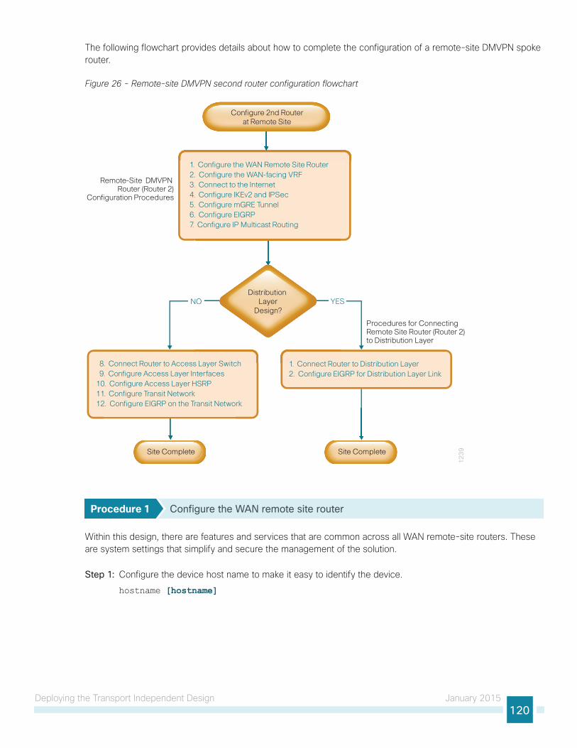
Deploying the Transport Independent Design January 2015120
The following flowchart provides details about how to complete the configuration of a remote-site DMVPN spoke router.
Figure 26 - Remote-site DMVPN second router configuration flowchart
12
39
1. Configure the WAN Remote Site Router2. Configure the WAN-facing VRF3. Connect to the Internet4. Configure IKEv2 and IPSec5. Configure mGRE Tunnel6. Configure EIGRP7. Configure IP Multicast Routing
Procedures for ConnectingRemote Site Router (Router 2) to Distribution Layer
Remote-Site DMVPN Router (Router 2)
Configuration Procedures
YESNO
8. Connect Router to Access Layer Switch 9. Configure Access Layer Interfaces10. Configure Access Layer HSRP11. Configure Transit Network12. Configure EIGRP on the Transit Network
1. Connect Router to Distribution Layer2. Configure EIGRP for Distribution Layer Link
Site Complete
YESNO
s Layer Switch 1 Connect Rou
Distribution Layer
Design?
Site Complete
Configure 2nd Routerat Remote Site
Procedure 1 Configure the WAN remote site router
Within this design, there are features and services that are common across all WAN remote-site routers. These are system settings that simplify and secure the management of the solution.
Step 1: Configure the device host name to make it easy to identify the device.
hostname [hostname]
Deploying the Transport Independent Design January 2015121
Step 2: Configure local login and password.
The local login account and password provides basic access authentication to a router which provides only limited operational privileges. The enable password secures access to the device configuration mode. By enabling password encryption, you prevent the disclosure of plain text passwords when viewing configuration files.
username admin secret c1sco123enable secret c1sco123service password-encryption
aaa new-model
By default, https access to the router will use the enable password for authentication.
Step 3: (Optional) Configure centralized user authentication.
As networks scale in the number of devices to maintain it poses an operational burden to maintain local user accounts on every device. A centralized AAA service reduces operational tasks per device and provides an audit log of user access for security compliance and root cause analysis. When AAA is enabled for access control, all management access to the network infrastructure devices (SSH and HTTPS) is controlled by AAA.
TACACS+ is the primary protocol used to authenticate management logins on the infrastructure devices to the AAA server. A local AAA user database is also defined on each network infrastructure device to provide a fallback authentication source in case the centralized TACACS+ server is unavailable.
tacacs server TACACS-SERVER-1 address ipv4 10.4.48.15 key SecretKey
aaa group server tacacs+ TACACS-SERVERS server name TACACS-SERVER-1
aaa authentication login default group TACACS-SERVERS localaaa authorization exec default group TACACS-SERVERS localaaa authorization console
ip http authentication aaa
Step 4: Configure device management protocols.
HTTPS and SSH are secure replacements for the HTTP and Telnet protocols. They use SSL and TLS to provide device authentication and data encryption.
Secure management of the network device is enabled through the use of the SSH and HTTPS protocols. Both protocols are encrypted for privacy and the nonsecure protocols, Telnet and HTTP, are turned off. SCP is enabled, which allows the use of code upgrades using Prime Infrastructure via SSH-based SCP protocol.

Deploying the Transport Independent Design January 2015122
Specify the transport preferred none on vty lines in order to prevent errant connection attempts from the CLI prompt. Without this command, if the ip name-server is unreachable, long timeout delays may occur for mistyped commands.
ip domain-name cisco.localip ssh version 2
no ip http server
ip http secure-server
ip scp server enable
line vty 0 15
transport input ssh
transport preferred none
Step 5: When synchronous logging of unsolicited messages and debug output is turned on, console log messages are displayed on the console after interactive CLI output is displayed or printed. With this command, you can continue typing at the device console when debugging is enabled.
line con 0
transport preferred none
logging synchronous
Step 6: Enable SNMP. This allows the network infrastructure devices to be managed by an NMS. SNMPv2c is configured both for a read-only and a read-write community string.
snmp-server community cisco RO snmp-server community cisco123 RWsnmp-server ifindex persist ! IOS Classic Only
snmp ifmib ifindex persist ! IOS XE Only
Step 7: (Optional) In networks where network operational support is centralized, you can increase network security by using an access list to limit the networks that can access your device. In this example, only devices on the 10.4.48.0/24 network will be able to access the device via SSH or SNMP.
access-list 55 permit 10.4.48.0 0.0.0.255line vty 0 15
access-class 55 in
snmp-server community cisco RO 55 snmp-server community cisco123 RW 55snmp-server ifindex persist ! IOS Classic Only
snmp ifmib ifindex persist ! IOS XE Only
If you configure an access-list on the vty interface, you may lose the ability to use ssh to login from one router to the next for hop-by-hop troubleshooting.
Tech Tip
Step 8: Configure a synchronized clock.
NTP is designed to synchronize a network of devices. An NTP network usually gets its time from an authoritative time source, such as a radio clock or an atomic clock attached to a time server. NTP then distributes this time across the organizations network.

Deploying the Transport Independent Design January 2015123
You should program network devices to synchronize to a local NTP server in the network. The local NTP server typically references a more accurate clock feed from an outside source. By configuring console messages, logs, and debug output to provide time stamps on output, you can cross-reference events in a network.
ntp server 10.4.48.17ntp update-calendar
clock timezone PST -8 clock summer-time PDT recurring
service timestamps debug datetime msec localtime
service timestamps log datetime msec localtime
Step 9: Configure an in-band management interface.
The loopback interface is a logical interface that is always reachable as long as the device is powered on and any IP interface is reachable to the network. Because of this capability, the loopback address is the best way to manage the router in-band. Layer 3 process and features are also bound to the loopback interface to ensure process resiliency.
The loopback address is commonly a host address with a 32-bit address mask. Allocate the loopback address from a unique network range that is not part of any other internal network summary range.
interface Loopback 0
ip address [ip address] 255.255.255.255 ip pim sparse-mode
The ip pim sparse-mode command will be explained further in the process.
Bind the device processes for SNMP, SSH, PIM, TACACS+ and NTP to the loopback interface address for optimal resiliency:
snmp-server trap-source Loopback0
ip ssh source-interface Loopback0
ip pim register-source Loopback0
ip tacacs source-interface Loopback0
ntp source Loopback0
Step 10: Configure IP Multicast routing.
In this design, which is based on sparse mode multicast operation, Auto RP is used to provide a simple yet scalable way to provide a highly resilient RP environment.
Enable IP Multicast routing on the platforms in the global configuration mode.
ip multicast-routing
Every Layer 3 switch and router must be configured to discover the IP Multicast RP with autorp. Use the ip pim autorp listener command to allow for discovery across sparse mode links. This configuration provides for future scaling and control of the IP Multicast environment and can change based on network needs and design.
ip pim autorp listener
All Layer 3 interfaces in the network must be enabled for sparse mode multicast operation.
ip pim sparse-mode

Deploying the Transport Independent Design January 2015124
Procedure 2 Configure the WAN-facing VRF
A WAN-facing VRF is created to support FVRF for DMVPN. The VRF name is arbitrary, but it is useful to select a name that describes the VRF. The VRF must be enabled for IPv4.
Table 49 - VRF assignments
IWAN Design Model Primary WAN VRF Secondary WAN VRF
Hybrid IWAN-TRANSPORT-1 IWAN-TRANSPORT-2
Dual Internet IWAN-TRANSPORT-3 IWAN-TRANSPORT-4
This design uses VRF Lite, so the selection is only locally significant to the device. It is a best practice to use the same VRF/RD combination across multiple devices when using VRFs in a similar manner. However, this convention is not strictly required.
Step 1: Configure the secondary WAN VRF.
Example: Transport 2 in the IWAN hybrid design modelvrf definition IWAN-TRANSPORT-2 address-family ipv4
Procedure 3 Connect to the Internet
The remote sites using DMVPN can use either static or dynamically assigned IP addresses. Cisco tested the design with a DHCP assigned external address, which also provides a dynamically configured default route.
The DMVPN spoke router connects directly to the Internet without a separate firewall. This connection is secured in two ways. Because the Internet interface is in a separate VRF, no traffic can access the global VRF except traffic sourced through the DMVPN tunnel. This design provides implicit security. Additionally, an IP access list permits only the traffic required for an encrypted tunnel, as well as DHCP and various ICMP protocols for troubleshooting.
Step 1: Enable the interface, select VRF and enable DHCP.
The DMVPN design uses FVRF, so you must place this interface into the VRF configured in the previous procedure.
interface GigabitEthernet0/0 vrf forwarding IWAN-TRANSPORT-2 ip address dhcp
no cdp enable
no shutdown
Do not enable PIM on this interface because no multicast traffic should be requested from this interface.

Deploying the Transport Independent Design January 2015125
Step 2: Configure and apply the access list.
The IP access list must permit the protocols specified in the following table. The access list is applied inbound on the WAN interface, so filtering is done on traffic destined to the router.
Table 50 - Required DMVPN protocols
Name Protocol Usage
non500-isakmp UDP 4500 IPsec via NAT-T
isakmp UDP 500 ISAKMP
esp IP 50 IPsec
bootpc UDP 68 DHCP
Exampleinterface GigabitEthernet0/0 ip access-group ACL-INET-PUBLIC in
ip access-list extended ACL-INET-PUBLIC permit udp any any eq non500-isakmp
permit udp any any eq isakmp
permit esp any any
permit udp any any eq bootpc
The additional protocols listed in the following table may assist in troubleshooting, but are not explicitly required to allow DMVPN to function properly.
Table 51 - Optional protocols: DMVPN spoke router
Name Protocol Usage
icmp echo ICMP Type 0, Code 0 Allow remote pings
icmp echo-reply ICMP Type 8, Code 0 Allow ping replies (from your requests)
icmp ttl-exceeded ICMP Type 11, Code 0 Allow traceroute replies (from your requests)
icmp port-unreachable ICMP Type 3, Code 3 Allow traceroute replies (from your requests)
UDP high ports UDP > 1023, TTL=1 Allow remote traceroute
IOS CA Port 80 172.16.140.110 on TCP / 80 Allow IOS CA to communicate with router during enrollment
The additional optional entries for an access list to support ping are as follows:
permit icmp any any echo
permit icmp any any echo-reply
The additional optional entries for an access list to support traceroute are as follows:
permit icmp any any ttl-exceeded ! for traceroute (sourced)
permit icmp any any port-unreachable ! for traceroute (sourced)
permit udp any any gt 1023 ttl eq 1 ! for traceroute (destination)
The additional optional entry for an access list to support IOS CA at the Internet DMZ address 172.16.140.11 on source port 80 is as follows:
permit tcp host 172.16.140.110 eq www any

Deploying the Transport Independent Design January 2015126
Procedure 4 Configure IKEv2 and IPsec
This procedure uses the parameters in the tables below. Choose the table that represents the design model that you are configuring. This procedure applies to the Secondary WAN.
Table 52 - Crypto parameters: IWAN hybrid design model
Parameter Primary WAN Secondary WAN
vrf IWAN-TRANSPORT-1 IWAN-TRANSPORT-2
crypto ikev2 keyring DMVPN-KEYRING-1 DMVPN-KEYRING-2
crypto ikev2 profile FVRF-IKEv2-IWAN-TRANSPORT-1 FVRF-IKEv2-IWAN-TRANSPORT-2
crypto ipsec profile DMVPN-PROFILE-TRANSPORT-1 DMVPN-PROFILE-TRANSPORT-2
Table 53 - Crypto parameters: IWAN dual Internet design model
Parameter Primary WAN Secondary WAN
vrf IWAN-TRANSPORT-3 IWAN-TRANSPORT-4
crypto ikev2 keyring DMVPN-KEYRING-3 DMVPN-KEYRING-4
crypto ikev2 profile FVRF-IKEv2-IWAN-TRANSPORT-3 FVRF-IKEv2-IWAN-TRANSPORT-4
crypto ipsec profile DMVPN-PROFILE-TRANSPORT-3 DMVPN-PROFILE-TRANSPORT-4
IPsec uses a key exchange between the routers in order to encrypt/decrypt the traffic. These keys can be exchanged using a simple pre-sharing algorithm or a certificate authority. It is also possible to use a combination of the two, which is useful during a migration from one method to the other. Choose one of two options below as your method of key exchange.
Option 1: Configure with Pre-Shared Keys
Step 1: Configure the crypto keyring for pre-shared keys.
The crypto keyring defines a pre-shared key (or password) valid for IP sources that are reachable within a particular VRF. This key is a wildcard pre-shared key if it applies to any IP source. A wildcard key is configured using the 0.0.0.0 0.0.0.0 network/mask combination.
crypto ikev2 keyring [keyring name] peer ANY address 0.0.0.0 0.0.0.0 pre-shared-key [password]
Example: Secondary WAN in the IWAN hybrid design modelcrypto ikev2 keyring DMVPN-KEYRING-2 peer ANY address 0.0.0.0 0.0.0.0 pre-shared-key c1sco123

Deploying the Transport Independent Design January 2015127
Step 2: Configure the IKEv2 profile.
The default IKEv2 proposal is used, which includes the following:
• Encryption with AES cipher with a 256-bit key
• Integrity with SHA with 512-bit digest
• Pseudo-random function with SHA with 512-bit digest
• Diffie-Hellman group: 5
RS12-2911-2# show crypto ikev2 proposalIKEv2 proposal: default
Encryption: AES-CBC-256 AES-CBC-192 AES-CBC-128
Integrity : SHA512 SHA384 SHA256 SHA96 MD596
PRF : SHA512 SHA384 SHA256 SHA1 MD5
DH Group : DH_GROUP_1536_MODP/Group 5 DH_GROUP_1024_MODP/Group 2
The IKEv2 profile creates an association between an identity address, a VRF, and a crypto keyring. A wildcard address within a VRF is referenced with 0.0.0.0. The profile also defines what method of key sharing will be used on this router with authentication local and what methods will be accepted from remote locations with authentication remote. The pre-share keyword is used with the keyring defined above.
crypto ikev2 profile [profile name] match fvrf [vrf name] match identity remote address [IP address] authentication remote pre-share
authentication local pre-share
keyring local [keyring name]
Example: Secondary WAN in the IWAN hybrid design modelcrypto ikev2 profile FVRF-IKEv2-IWAN-TRANSPORT-2 match fvrf IWAN-TRANSPORT-2 match identity remote address 0.0.0.0 authentication remote pre-share
authentication local pre-share
keyring local DMVPN-KEYRING-2
Step 3: Configure DPD.
DPD is essential to facilitate fast reconvergence and for spoke registration to function properly in case a DMVPN hub is restarted. The IWAN design recommends you set the remote site DPD timer to 40 seconds with 5 a second retry.
crypto ikev2 dpd [interval in seconds] [retry interval] on-demand
Example crypto ikev2 dpd 40 5 on-demand
Step 4: Define the IPsec transform set.
A transform set is an acceptable combination of security protocols, algorithms, and other settings to apply to IPsec-protected traffic. Peers agree to use a particular transform set when protecting a particular data flow.

Deploying the Transport Independent Design January 2015128
The IPsec transform set for DMVPN uses the following:
• ESP with the 256-bit AES encryption algorithm
• ESP with the SHA (HMAC variant) authentication algorithm
Since the DMVPN hub router is behind a NAT device, the IPsec transform must be configured for transport mode.
crypto ipsec transform-set [transform set] esp-aes 256 esp-sha-hmac mode transport
Examplecrypto ipsec transform-set AES256/SHA/TRANSPORT esp-aes 256 esp-sha-hmac mode transport
Step 5: Configure the IPsec profile.
The IPsec profile creates an association between an IKEv2 profile and an IPsec transform-set.
crypto ipsec profile [profile name] set transform-set [transform set] set ikev2-profile [ikev2 profile name]
Example: Secondary WAN in the IWAN hybrid design modelcrypto ipsec profile DMVPN-PROFILE-TRANSPORT-2 set transform-set AES256/SHA/TRANSPORT set ikev2-profile FVRF-IKEv2-IWAN-TRANSPORT-2
Step 6: Increase the IPsec anti-replay window size.
crypto ipsec security-association replay window-size 1024
QoS queuing delays can cause anti-replay packet drops, so it is important to extend the window size to prevent the drops from occurring.
Increasing the anti-replay window size has no impact on throughput and security. The impact on memory is insignificant because only an extra 128 bytes per incoming IPsec SA are needed.
It is recommended that you use the full 1024 window size to eliminate future anti-replay problems.
If you do not increase the window size, the router may drop packets and you may see the following error message on the router CLI:
%CRYPTO-4-PKT_REPLAY_ERR: decrypt: replay check failed
Tech Tip
Step 7: Skip to the next procedure.

Deploying the Transport Independent Design January 2015129
Option 2: Configure with a Certificate AuthorityThe crypto pki trustpoint is the method of specifying the parameters associated with a CA. The router must authenticate to the CA first, and then enroll with the CA to obtain its own identity certificate.
Step 1: The fingerprint command limits the responding CA. This fingerprint can be found using show crypto pki server on the IOS CA.
IWAN-IOS-CA# show crypto pki server Certificate Server IWAN-IOS-CA:
Status: enabled
State: enabled
Server’s configuration is locked (enter "shut" to unlock it)
Issuer name: CN=IWAN-IOS-CA.cisco.local L=SanJose St=CA C=US
CA cert fingerprint: 75BEF625 9A9876CF 6F341FE5 86D4A5D8
Granting mode is: auto
Last certificate issued serial number (hex): 11
CA certificate expiration timer: 10:28:57 PST Nov 11 2017
CRL NextUpdate timer: 09:47:47 PST Dec 4 2014
Current primary storage dir: nvram:
Current storage dir for .crl files: nvram:
Database Level: Complete - all issued certs written as <serialnum>.cer
Table 54 - IOS CA IP address assignments
Network IP Address NAT IP Address
Internal 10.6.24.11 N/A
Internet DMZ 192.168.144.127 172.16.140.110 (ISP-A)
MPLS Provider 192.168.6.254 N/A
Step 2: Configure the PKI trust point.
crypto pki trustpoint [name] enrollment url [URL of IOS CA that is reachable] serial-number none
fqdn [fully qualified domain name of this router] ip-address [loopback IP address of this router] fingerprint [fingerprint from IOS CA] vrf [vrf name] revocation-check none
rsakeypair [name] 2048 2048

Deploying the Transport Independent Design January 2015130
Example: RS14-2921-2This example is from the second remote site router in the dual Internet design model. This router can only reach the IOS CA from the Internet and it uses the NAT IP address of 172.16.140.110 in VRF IWAN-TRANPORT-4 for enrollment.
crypto pki trustpoint IWAN-CA enrollment url http://172.16.140.110:80 serial-number none
fqdn RS14-2921-2.cisco.local ip-address 10.255.244.14 fingerprint 75BEF6259A9876CF6F341FE586D4A5D8 vrf IWAN-TRANPORT-4 revocation-check none
rsakeypair IWAN-CA-KEYS 2048 2048
Step 3: Authenticate to the CA and obtain the CA’s certificate
Exit the trustpoint configuration mode on the hub router and issue the following command to authenticate to the CA and get its certificate.
RS14-2921-2(config)# crypto pki authenticate IWAN-CACertificate has the following attributes:
Fingerprint MD5: 1A070F43 38068E1C BE04A8FB CBAA406F
Fingerprint SHA1: F463AAF1 54C4D994 E2732F36 3BEBED23 D410192E
Trustpoint Fingerprint: 1A070F43 38068E1C BE04A8FB CBAA406F
Certificate validated - fingerprints matched.
Trustpoint CA certificate accepted.
Step 4: Enroll with the CA, enter a password for key retrieval and obtain a certificate for this hub router.
RS14-2921-2(config)# crypto pki enroll IWAN-CA
% Start certificate enrollment ..
% Create a challenge password. You will need to verbally provide this
password to the CA Administrator in order to revoke your certificate.
For security reasons your password will not be saved in the configuration.
Please make a note of it.
Password: c1sco123Re-enter password: c1sco123
% The subject name in the certificate will include: RS14-2921-2.cisco.local
% The IP address in the certificate is 10.255.244.14
Request certificate from CA? [yes/no]: yes
% Certificate request sent to Certificate Authority
% The ‘show crypto pki certificate verbose IWAN-CA’ command will show the
fingerprint.
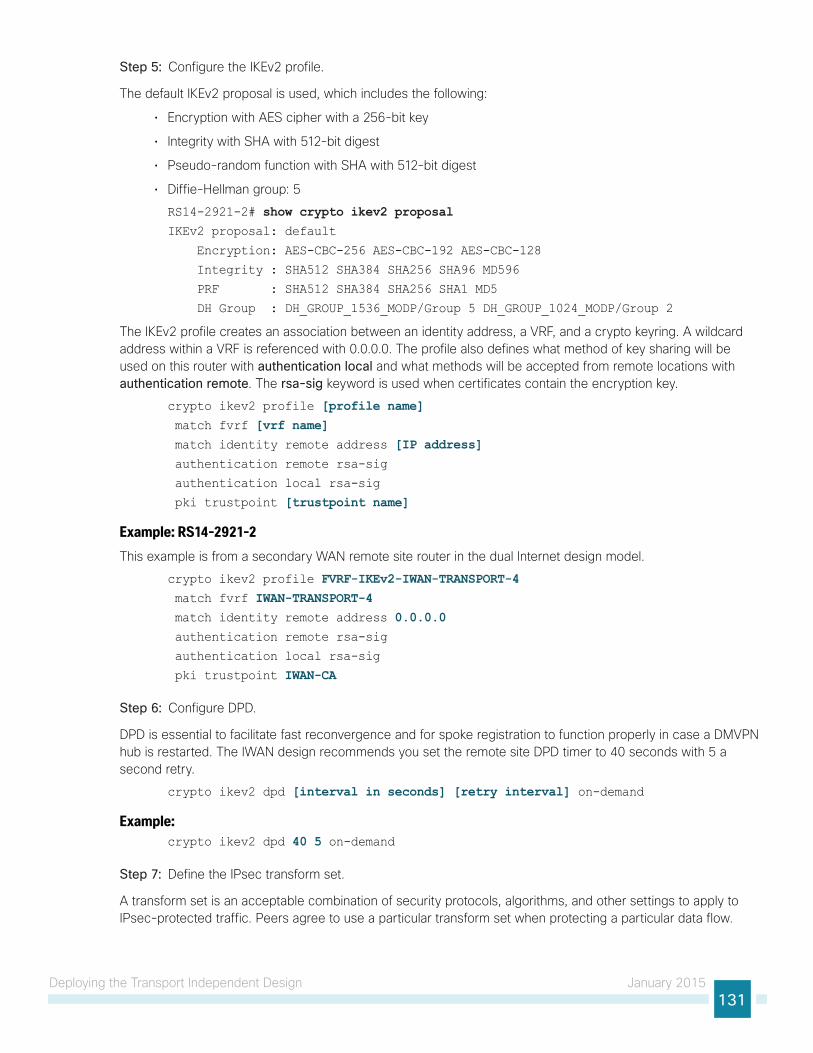
Deploying the Transport Independent Design January 2015131
Step 5: Configure the IKEv2 profile.
The default IKEv2 proposal is used, which includes the following:
• Encryption with AES cipher with a 256-bit key
• Integrity with SHA with 512-bit digest
• Pseudo-random function with SHA with 512-bit digest
• Diffie-Hellman group: 5
RS14-2921-2# show crypto ikev2 proposalIKEv2 proposal: default
Encryption: AES-CBC-256 AES-CBC-192 AES-CBC-128
Integrity : SHA512 SHA384 SHA256 SHA96 MD596
PRF : SHA512 SHA384 SHA256 SHA1 MD5
DH Group : DH_GROUP_1536_MODP/Group 5 DH_GROUP_1024_MODP/Group 2
The IKEv2 profile creates an association between an identity address, a VRF, and a crypto keyring. A wildcard address within a VRF is referenced with 0.0.0.0. The profile also defines what method of key sharing will be used on this router with authentication local and what methods will be accepted from remote locations with authentication remote. The rsa-sig keyword is used when certificates contain the encryption key.
crypto ikev2 profile [profile name] match fvrf [vrf name] match identity remote address [IP address] authentication remote rsa-sig
authentication local rsa-sig
pki trustpoint [trustpoint name]
Example: RS14-2921-2This example is from a secondary WAN remote site router in the dual Internet design model.
crypto ikev2 profile FVRF-IKEv2-IWAN-TRANSPORT-4 match fvrf IWAN-TRANSPORT-4 match identity remote address 0.0.0.0 authentication remote rsa-sig
authentication local rsa-sig
pki trustpoint IWAN-CA
Step 6: Configure DPD.
DPD is essential to facilitate fast reconvergence and for spoke registration to function properly in case a DMVPN hub is restarted. The IWAN design recommends you set the remote site DPD timer to 40 seconds with 5 a second retry.
crypto ikev2 dpd [interval in seconds] [retry interval] on-demand
Example: crypto ikev2 dpd 40 5 on-demand
Step 7: Define the IPsec transform set.
A transform set is an acceptable combination of security protocols, algorithms, and other settings to apply to IPsec-protected traffic. Peers agree to use a particular transform set when protecting a particular data flow.

Deploying the Transport Independent Design January 2015132
The IPsec transform set for DMVPN uses the following:
• ESP with the 256-bit AES encryption algorithm
• ESP with the SHA (HMAC variant) authentication algorithm
Because the DMVPN hub router is behind a NAT device, the IPsec transform must be configured for transport mode.
crypto ipsec transform-set [transform set] esp-aes 256 esp-sha-hmac mode transport
Examplecrypto ipsec transform-set AES256/SHA/TRANSPORT esp-aes 256 esp-sha-hmac mode transport
Step 8: Configure the IPSec profile.
The IPsec profile creates an association between an IKEv2 profile and an IPsec transform-set.
crypto ipsec profile [profile name] set transform-set [transform set] set ikev2-profile [ikev2 profile name]
Example: RS14-2921-2This example is from a secondary WAN remote site router in the dual Internet design model.
crypto ipsec profile DMVPN-PROFILE-TRANSPORT-4 set transform-set AES256/SHA/TRANSPORT set ikev2-profile FVRF-IKEv2-IWAN-TRANSPORT-4
Step 9: Increase the IPsec anti-replay window size.
crypto ipsec security-association replay window-size [value]
Examplecrypto ipsec security-association replay window-size 512
QoS queuing delays can cause anti-replay packet drops, so it is important to extend the window size to prevent the drops from occurring.
Increasing the anti-replay window size has no impact on throughput and security. The impact on memory is insignificant because only an extra 128 bytes per incoming IPsec SA is needed.
It is recommended that you use the maximum window size to eliminate future anti-replay problems. On the Cisco ASR 1000 router platform, the maximum replay window size is 512
If you do not increase the window size, the router may drop packets and you may see the following error message on the router CLI:
%CRYPTO-4-PKT_REPLAY_ERR: decrypt: replay check failed
Tech Tip

Deploying the Transport Independent Design January 2015133
Procedure 5 Configure the mGRE tunnel
This procedure uses the parameters in the table below. Choose the rows that represent the design model that you are configuring. This procedure applies to the Secondary WAN.
Table 55 - DMVPN tunnel parameters
IWAN Design Model Tunnel VRFTunnel Number Tunnel Network
NHRP network ID / Tunnel Key
Hybrid—Primary WAN IWAN-TRANSPORT-1 10 10.6.34.0/23 101
Hybrid—Secondary WAN IWAN-TRANSPORT-2 11 10.6.36.0/23 102
Dual Internet—Primary WAN IWAN-TRANSPORT-3 20 10.6.38.0/23 201
Dual Internet—Secondary WAN IWAN-TRANSPORT-4 21 10.6.40.0/23 202
Step 1: Configure basic interface settings.
The tunnel number is arbitrary, but it is best to begin tunnel numbering at 10 or above, because other features deployed in this design may also require tunnels and they may select lower numbers by default.
You must set the bandwidth setting to match the bandwidth of the respective transport, which corresponds to the actual interface speed. Or, if you are using a subrate service, use the policed rate from the carrier. QoS and PfR require the correct bandwidth setting to operate properly.
Configure the ip mtu to 1400 and the ip tcp adjust-mss to 1360. There is a 40 byte difference, which corresponds to the combined IP and TCP header length.
The tunnel interface throughput delay setting should be set to influence the routing protocol path preference. Set the primary WAN path to 10000 usec and the secondary WAN path to 20000 usec to prefer one over the other. The delay command is entered in 10 usec units.
interface Tunnel11 bandwidth 10000 ip address 10.6.36.12 255.255.254.0 no ip redirects
ip mtu 1400
ip tcp adjust-mss 1360
delay 2000
Step 2: Configure the tunnel.
DMVPN uses multipoint GRE (mGRE) tunnels. This type of tunnel requires a source interface only. The source interface should be the same interface you use to connect to the Internet. You should set the tunnel vrf command to the VRF defined previously for FVRF.
To enable encryption on this interface, you must apply the IPsec profile that you configured in the previous procedure.
interface Tunnel11 tunnel source GigabitEthernet0/0 tunnel mode gre multipoint
tunnel key 102 tunnel vrf IWAN-TRANSPORT-2 tunnel protection ipsec profile DMVPN-PROFILE-TRANSPORT-2

Deploying the Transport Independent Design January 2015134
Step 3: Configure NHRP.
The spoke router requires an additional configuration statement to define the NHRP server (NHS). This statement includes the NBMA definition for the DMVPN hub router tunnel endpoint. EIGRP relies on a multicast transport. Spoke routers require the NHRP multicast keyword in this statement.
The value used for the NHS is the mGRE tunnel address for the DMVPN hub router. The nbma entry must be set to either the MPLS DMVPN hub router’s actual public address or the outside NAT value of the DMVPN hub, as configured on the Cisco ASA 5500. This design uses the values shown in the following tables.
Table 56 - DMVPN tunnel NHRP parameters: IWAN hybrid design model
Transport 1 Transport 2
VRF IWAN-TRANSPORT-1 IWAN-TRANSPORT-2
DMVPN hub public address (actual) 192.168.6.1 192.168.146.10
DMVPN hub public address (externally routable after NAT)
n/a (MPLS) 172.16.140.1
DMVPN hub tunnel IP address (NHS) 10.6.34.1 10.6.36.1
Tunnel number 10 11
NHRP network ID 101 102
Table 57 - DMVPN tunnel NHRP parameters: IWAN dual Internet design model
Transport 3 Transport 4
VRF IWAN-TRANSPORT-3 IWAN-TRANSPORT-4
DMVPN hub public address (actual) 192.168.146.20 192.168.146.21
DMVPN hub public address (externally routable after NAT)
172.16.140.11 172.17.140.11
DMVPN tub tunnel IP address (NHS) 10.6.38.1 10.6.40.1
Tunnel number 20 21
NHRP network ID 201 202
NHRP requires all devices within a DMVPN cloud to use the same network ID and authentication key. The NHRP cache holdtime should be configured to 600 seconds.
This design supports DMVPN spoke routers that receive their external IP addresses through DHCP. It is possible for these routers to acquire different IP addresses after a reload. When the router attempts to register with the NHRP server, it may appear as a duplicate to an entry already in the cache and be rejected. The registration no-unique option allows you to overwrite existing cache entries. This feature is only required on NHRP clients (DMVPN spoke routers). The if-state nhrp option ties the tunnel line-protocol state to the reachability of the NHRP NHS, and if the NHS is unreachable the tunnel line-protocol state changes to down.

Deploying the Transport Independent Design January 2015135
This feature is used in conjunction with EOT.
interface Tunnel11 ip nhrp authentication cisco123 ip nhrp network-id 102 ip nhrp holdtime 600 ip nhrp nhs 10.6.36.1 nbma 172.16.140.1 multicast ip nhrp registration no-unique
ip nhrp shortcut
if-state nhrp
Procedure 6 Configure EIGRP
A single EIGRP process runs on the DMVPN spoke router. All interfaces on the router are EIGRP interfaces, but only the DMVPN tunnel interface is non-passive. The network range must include all interface IP addresses either in a single network statement or in multiple network statements. This design uses a best practice of assigning the router ID to a loopback address. All DMVPN spoke routers should run EIGRP stub routing to improve network stability and reduce resource utilization.
Step 1: Configure an EIGRP process for DMVPN by using EIGRP named mode on the spoke router.
router eigrp IWAN-EIGRP address-family ipv4 unicast autonomous-system 400 af-interface default
passive-interface
exit-af-interface
af-interface Tunnel11 no passive-interface
exit-af-interface
network 10.6.36.0 0.0.1.255network 10.7.0.0 0.0.255.255network 10.255.0.0 0.0.255.255eigrp router-id [IP address of Loopback0]eigrp stub connected summary redistributed
exit-address-family
Step 2: Configure EIGRP values for the mGRE tunnel interface.
The EIGRP hello interval is increased to 20 seconds and the EIGRP hold time is increased to 60 seconds in order to accommodate up to 2000 remote sites on a single DMVPN cloud. Increasing the EIGRP timers also slows down the routing convergence to improve network stability and the IWAN design allows PfR to initiate the fast failover, so changing the timers is recommended for all IWAN deployments.
router eigrp IWAN-EIGRP address-family ipv4 unicast autonomous-system 400 af-interface Tunnel11 hello-interval 20 hold-time 60 exit-af-interface
exit-address-family

Deploying the Transport Independent Design January 2015136
Step 3: Configure EIGRP neighbor authentication. Neighbor authentication enables the secure establishment of peering adjacencies and exchange route tables over the DMVPN tunnel interface.
key chain WAN-KEY key 1
key-string c1sco123
router eigrp IWAN-EIGRP address-family ipv4 unicast autonomous-system 400 af-interface Tunnel11 authentication mode md5
authentication key-chain WAN-KEY exit-af-interface
exit-address-family
Step 4: Configure EIGRP network summarization.
The remote-site LAN networks must be advertised. The IP assignment for the remote sites was designed so that all of the networks in use can be summarized within a single aggregate route. The summary address as configured below suppresses the more specific routes. If any network within the summary is present in the route table, the summary is advertised to the DMVPN hub, which offers a measure of resiliency. If the various LAN networks cannot be summarized, then EIGRP continues to advertise the specific routes.
router eigrp IWAN-EIGRP address-family ipv4 unicast autonomous-system 400 af-interface Tunnel10 summary-address [summary network] [summary mask] exit-af-interface
exit-address-family
Procedure 7 Configure IP multicast routing
This procedure includes additional steps for configuring IP Multicast for a DMVPN tunnel on a router with IP Multicast already enabled.
Step 1: Configure PIM on the DMVPN tunnel interface.
Enable IP PIM sparse mode on the DMVPN tunnel interface.
interface Tunnel11 ip pim sparse-mode
Step 2: Enable PIM NBMA mode for the DMVPN tunnel.
Spoke-to-spoke DMVPN networks present a unique challenge because the spokes cannot directly exchange information with one another, even though they are on the same logical network. This inability to directly exchange information can also cause problems when running IP Multicast.
To resolve the NBMA issue, you need to implement a method where each remote PIM neighbor has its join messages tracked separately. A router in PIM NBMA mode treats each remote PIM neighbor as if it were connected to the router through a point-to-point link.
interface Tunnel11 ip pim nbma-mode

Deploying the Transport Independent Design January 2015137
Step 3: Configure the DR priority for the DMVPN spoke router.
Proper multicast operation across a DMVPN cloud requires that the hub router assumes the role of PIM DR. Spoke routers should never become the DR. You can prevent that by setting the DR priority to 0 for the spokes.
interface Tunnel11 ip pim dr-priority 0
Procedure 8 Connect router to access layer switch
OptionalIf you are using a remote-site distribution layer, skip to the “Connecting Remote-Site Router to Distribution Layer (Router 2)” process.
This guide includes only the additional steps needed to complete the access layer configuration. For complete access layer configuration details, refer to the Campus Wired LAN Technology Design Guide .
Reader Tip
Layer 2 EtherChannels are used to interconnect the router to the access layer in the most resilient method possible, unless the access layer device is a single fixed configuration switch, Otherwise a simple Layer 2 trunk between the router and switch is used.
In the access layer design, the remote sites use collapsed routing, with 802.1Q trunk interfaces to the LAN access layer. The VLAN numbering is locally significant only.
Option 1: Layer 2 EtherChannel from router to access layer switch
Step 1: Configure port-channel interface on the router.
interface Port-channel2 description EtherChannel link to RS12-A2960X no shutdown
Step 2: Configure EtherChannel member interfaces on the router.
Configure the physical interfaces to tie to the logical port-channel using the channel-group command. The number for the port-channel and channel-group must match. Not all router platforms can support LACP to negotiate with the switch, so EtherChannel is configured statically.
interface GigabitEthernet0/1 description RS12-A2960X Gig1/0/48
interface GigabitEthernet0/2 description RS12-A2960X Gig2/0/48
interface range GigabitEthernet0/1, GigabitEthernet0/2 no ip address
channel-group 2 no shutdown

Deploying the Transport Independent Design January 2015138
Step 3: Configure EtherChannel member interfaces on the access layer switch.
Connect the router EtherChannel uplinks to separate switches in the access layer switch stack, or in the case of the Cisco Catalyst 4507R+E distribution layer, to separate redundant modules for additional resiliency.
The physical interfaces that are members of a Layer 2 EtherChannel are configured prior to configuring the logical port-channel interface. Doing the configuration in this order allows for minimal configuration and reduces errors because most of the commands entered to a port-channel interface are copied to its members interfaces and do not require manual replication.
Configure two or more physical interfaces to be members of the EtherChannel. It is recommended that they are added in multiples of two. Also, apply the egress QoS macro that was defined in the platform configuration procedure to ensure traffic is prioritized appropriately.
Not all connected router platforms can support LACP to negotiate with the switch, so EtherChannel is configured statically.
interface GigabitEthernet1/0/48 description Link to RS12-2911-2 Gig0/1
interface GigabitEthernet2/0/48 description Link to RS12-2911-2 Gig0/2
interface range GigabitEthernet1/0/48, GigabitEthernet2/0/48 switchport
channel-group 2 mode on logging event link-status
logging event trunk-status
logging event bundle-status
load-interval 30
macro apply EgressQoS
Step 4: Configure EtherChannel trunk on the access layer switch.
An 802.1Q trunk is used which allows the router to provide the Layer 3 services to all the VLANs defined on the access layer switch. The VLANs allowed on the trunk are pruned to only the VLANs that are active on the access layer switch. When using EtherChannel the interface type will be port-channel and the number must match the channel group configured in Step 3. DHCP Snooping and ARP inspection are set to trust.
interface Port-channel2 description EtherChannel link to RS12-2911-2 switchport trunk allowed vlan 64,69,99 switchport mode trunk
ip arp inspection trust
spanning-tree portfast trunk
ip dhcp snooping trust
load-interval 30
no shutdown
The Cisco Catalyst 3750 Series Switch requires the switchport trunk encapsulation dot1q command

Deploying the Transport Independent Design January 2015139
Option 2: Layer 2 trunk from router to access layer switch
Step 1: Enable the physical interface on the router.
interface GigabitEthernet0/2 description RS12-A2960X Gig1/0/48 no ip address
no shutdown
Step 2: Configure the trunk on the access layer switch.
Use an 802.1Q trunk for the connection, which allows the router to provide the Layer 3 services to all the VLANs defined on the access layer switch. The VLANs allowed on the trunk are pruned to only the VLANs that are active on the access switch. DHCP Snooping and ARP inspection are set to trust.
interface GigabitEthernet1/0/48 description Link to RS12-2911-2 Gig0/2 switchport trunk allowed vlan 64,69,99 switchport mode trunk
ip arp inspection trust
spanning-tree portfast trunk
logging event link-status
logging event trunk-status
ip dhcp snooping trust
no shutdown
load-interval 30
macro apply EgressQoS
The Cisco Catalyst 3750 Series Switch requires the switchport trunk encapsulation dot1q command.
Procedure 9 Configure access layer interfaces
Step 1: Create subinterfaces and assign VLAN tags.
After the physical interface or port-channel have been enabled, then the appropriate data or voice subinterfaces can be mapped to the VLANs on the LAN switch. The subinterface number does not need to equate to the 802.1Q tag, but making them the same simplifies the overall configuration. The subinterface portion of the configuration should be repeated for all data or voice VLANs.
interface [type][number].[sub-interface number] encapsulation dot1Q [dot1q VLAN tag]
Step 2: Configure IP settings for each subinterface.
This design uses an IP addressing convention with the default gateway router assigned an IP address and IP mask combination of N.N.N.1 255.255.255.0 where N.N.N is the IP network and 1 is the IP host.
When you are using a centralized DHCP server, your routers with LAN interfaces connected to a LAN using DHCP for end-station IP addressing must use an IP helper.

Deploying the Transport Independent Design January 2015140
This remote-site DMVPN spoke router is the second router of a dual-router design and HSRP is configured at the access layer. The actual interface IP assignments will be configured in the following procedure.
interface [type][number].[sub-interface number] description [usage] encapsulation dot1Q [dot1q VLAN tag] ip helper-address 10.4.48.10 ip pim sparse-mode
Example: Layer 2 EtherChannelinterface Port-channel2 no ip address
no shutdown
interface Port-channel2.64 description Data encapsulation dot1Q 64 ip helper-address 10.4.48.10 ip pim sparse-mode
interface Port-channel2.69 description Voice encapsulation dot1Q 69 ip helper-address 10.4.48.10 ip pim sparse-mode
Example: Layer 2 Linkinterface GigabitEthernet0/2 no ip address
no shutdown
interface GigabitEthernet0/2.64 description Data encapsulation dot1Q 64 ip helper-address 10.4.48.10 ip pim sparse-mode
interface GigabitEthernet0/2.69 description Voice encapsulation dot1Q 69 ip helper-address 10.4.48.10 ip pim sparse-mode

Deploying the Transport Independent Design January 2015141
Procedure 10 Configure access layer HSRP
You configure HSRP to enable a VIP that you use as a default gateway that is shared between two routers. The HSRP active router is the router connected to the primary carrier and the HSRP standby router is the router connected to the secondary carrier or backup link. Configure the HSRP standby router with a standby priority that is lower than the HSRP active router.
The router with the higher standby priority value is elected as the HSRP active router. The preempt option allows a router with a higher priority to become the HSRP active, without waiting for a scenario where there is no router in the HSRP active state. The relevant HSRP parameters for the router configuration are shown in the following table.
Table 58 - WAN remote-site HSRP parameters (dual router)
Router HSRP role Virtual IP address (VIP) Real IP address HSRP priority PIM DR priority
Primary Active .1 .2 110 110
Secondary Standby .1 .3 105 105
The dual-router access-layer design requires a modification for resilient multicast. The PIM DR should be on the HSRP active router. The DR is normally elected based on the highest IP address and has no awareness of the HSRP configuration. In this design, the HSRP active router has a lower real IP address than the HSRP standby router, which requires a modification to the PIM configuration. The PIM DR election can be influenced by explicitly setting the DR priority on the LAN-facing subinterfaces for the routers.
The HSRP priority and PIM DR priority are shown in the previous table to be the same value; however there is no requirement that these values must be identical.
Tech Tip
Repeat this procedure for all data or voice subinterfaces.
interface [interface type][number].[sub-interface number] ip address [LAN network 1 address] [LAN network 1 netmask] ip pim dr-priority 105 standby version 2
standby 1 ip [LAN network 1 gateway address] standby 1 priority 105 standby 1 preempt standby 1 authentication md5 key-string c1sco123
Example: Layer 2 EtherChannelinterface PortChannel2 no ip address
no shutdown
interface PortChannel2.64 description Data encapsulation dot1Q 64

Deploying the Transport Independent Design January 2015142
ip address 10.7.18.3 255.255.255.0 ip helper-address 10.4.48.10 ip pim dr-priority 105 ip pim sparse-mode
standby version 2
standby 1 ip 10.7.18.1 standby 1 priority 105 standby 1 preempt standby 1 authentication md5 key-string c1sco123
interface PortChannel2.69 description Voice encapsulation dot1Q 69 ip address 10.7.19.3 255.255.255.0 ip helper-address 10.4.48.10 ip pim dr-priority 105 ip pim sparse-mode
standby version 2
standby 1 ip 10.7.19.1 standby 1 priority 105 standby 1 preempt standby 1 authentication md5 key-string c1sco123
Example: Layer 2 Linkinterface GigabitEthernet0/2 no ip address
no shutdown
interface GigabitEthernet0/2.64 description Data encapsulation dot1Q 64 ip address 10.7.18.3 255.255.255.0 ip helper-address 10.4.48.10 ip pim dr-priority 105 ip pim sparse-mode
standby version 2
standby 1 ip 10.7.18.1 standby 1 priority 105 standby 1 preempt standby 1 authentication md5 key-string c1sco123
interface GigabitEthernet0/2.69 description Voice encapsulation dot1Q 69 ip address 10.7.19.3 255.255.255.0 ip helper-address 10.4.48.10 ip pim dr-priority 105

Deploying the Transport Independent Design January 2015143
ip pim sparse-mode
standby version 2
standby 1 ip 10.7.19.1 standby 1 priority 105 standby 1 preempt standby 1 authentication md5 key-string c1sco123
Procedure 11 Configure transit network
Configure the transit network between the two routers. You use this network for router-router communication and to avoid hairpinning. The transit network should use an additional subinterface on the router interface that is already being used for data or voice.
There are no end stations connected to this network, so HSRP and DHCP are not required.
interface [interface type][number].[sub-interface number] encapsulation dot1Q [dot1q VLAN tag] ip address [transit net address] [transit net netmask] ip pim sparse-mode
Example: Layer 2 EtherChannelinterface PortChannel0/2.99 description Transit Net encapsulation dot1Q 99 ip address 10.7.16.10 255.255.255.252 ip pim sparse-mode
Example: Layer 2 Linkinterface GigabitEthernet0/2.99 description Transit Net encapsulation dot1Q 99 ip address 10.7.16.10 255.255.255.252 ip pim sparse-mode
Procedure 12 Configure EIGRP on the transit network
A single EIGRP process runs on the DMVPN spoke router, which has already been enabled during the configuration of the DMVPN tunnel. All interfaces on the router are EIGRP interfaces, but only the DMVPN tunnel interface and transit network are non-passive. The network range must include all interface IP addresses either in a single network statement or in multiple network statements.
EIGRP stub routers normally do not exchange routes with other stub routers, which is problematic in a dual router remote site. It is useful to maintain the benefits of EIGRP stub routing in this type of design. This requires the configuration of stub route leaking between the two remote-site routers for full route reachability. This is needed so that if a router loses its DMVPN link, it knows to how to reach the WAN from the other router at the branch.

Deploying the Transport Independent Design January 2015144
In order to prevent the remote site from becoming a transit site during certain failure conditions when stub route leaking is enabled, you must also configure a distribute-list on the tunnel interfaces to control route advertisement.
Step 1: Configure the transit network subinterface as non-passive.
router eigrp IWAN-EIGRP address-family ipv4 unicast autonomous-system 400 af-interface Port-channel2.99 no passive-interface
exit-af-interface
exit-address-family
Step 2: Configure EIGRP neighbor authentication. Neighbor authentication enables the secure establishment of peering adjacencies and exchange route tables over the transit network interface.
key chain LAN-KEY key 1
key-string c1sco123
router eigrp IWAN-EIGRP address-family ipv4 unicast autonomous-system 400 af-interface Port-channel2.99 authentication mode md5
authentication key-chain LAN-KEY exit-af-interface
exit-address-family
Step 3: Configure stub route leaking.
A simple route-map statement with no match statements matches all routes, which permits full route leaking between two routers configured as EIGRP stub.
route-map STUB-LEAK-ALL permit 100 description Leak all routes
router eigrp IWAN-EIGRP address-family ipv4 unicast autonomous-system 400 eigrp stub connected summary redistributed leak-map STUB-LEAK-ALL exit-address-family

Deploying the Transport Independent Design January 2015145
Step 4: Configure distribute-list to protect from becoming a transit site.
The route-map matches all routes learned from the WAN by matching on the tags set on the DMVPN hub routers in a previous process. The goal is to exchange full WAN routes between EIGRP stub routers, but to only advertise local prefixes out to the WAN over DMVPN.
route-map ROUTE-LIST deny 10 description Block readvertisement of learned WAN routes match tag 101 102
route-map ROUTE-LIST permit 100 description Advertise all other routes
router eigrp IWAN-EIGRP address-family ipv4 unicast autonomous-system 400 topology base
distribute-list route-map ROUTE-LIST out Tunnel11 exit-af-topology
exit-address-family

Deploying an IWAN Remote-Site Distribution Layer January 2015146
Deploying an IWAN Remote-Site Distribution Layer
Connecting Remote-site Router to Distribution Layer
1. Connect router to distribution layer
2. Configure EIGRP for distribution layer link
3. Configure transit network for dual router designPR
OC
ESS
This process helps you configure a DMVPN spoke router for an IWAN remote site and connect to a distribution layer.
This process covers the IWAN hybrid design model and the IWAN dual-Internet design model. Use this process to:
• Connect a distribution layer to a router in the single-router, dual-link design.
• Connect a distribution layer to the first router of the dual-router, dual-link design.
The distribution layer remote-site options are shown in the following figures.
Figure 27 - IWAN single router remote-site: Connection to distribution layer
12
22
VLAN 50 - Router 1 Link
802.1q Trunk (xx-xx)
802.1q Trunk (50)
802.1q Trunk (xx-xx)

Deploying an IWAN Remote-Site Distribution Layer January 2015147
Figure 28 - IWAN dual router remote-site: Connection to distribution layer
VLAN 50 - Router 1 Link
802.1q Trunk(xx-xx)
802.1q Trunk(xx-xx)
802.1q Trunk(50, 99)
802.1q Trunk(54, 99)
VLAN 54 - Router 2 LinkVLAN 99 - Transit 1
22
3
Procedure 1 Connect router to distribution layer
This guide includes only the additional steps for completing the distribution layer configuration. For complete distribution layer configuration details, see the Campus Wired LAN Technology Design Guide .
Reader Tip
Layer 2 EtherChannels are used to interconnect the remote-site router to the distribution layer in the most resilient method possible. This connection allows for multiple VLANs to be included on the EtherChannel as necessary.
Step 1: Configure port-channel interface on the router.
interface Port-channel1 description EtherChannel link to RS42-D3850 no shutdown
Step 2: Configure the port channel sub-interfaces and assign IP addresses.
After you have enabled the interface, map the appropriate sub-interfaces to the VLANs on the distribution layer switch. The sub-interface number does not need to equate to the 802.1Q tag, but making them the same simplifies the overall configuration.

Deploying an IWAN Remote-Site Distribution Layer January 2015148
The sub-interface configured on the router corresponds to a VLAN interface on the distribution-layer switch. Traffic is routed between the devices with the VLAN acting as a point-to-point link.
interface Port-channel1.50 description R1 routed link to distribution layer encapsulation dot1Q 50 ip address 10.7.208.1 255.255.255.252 ip pim sparse-mode
Step 3: Configure EtherChannel member interfaces on the router.
Configure the physical interfaces to tie to the logical port-channel using the channel-group command. The number for the port-channel and channel-group must match. Not all router platforms can support LACP to negotiate with the switch, so EtherChannel is configured statically.
interface GigabitEthernet0/0/2 description RS42-D3850 Gig1/1/1
interface GigabitEthernet0/0/3 description RS42-D3850 Gig2/1/1
interface range GigabitEthernet0/0/2, GigabitEthernet0/0/3 no ip address
channel-group 1 no shutdown
Step 4: Configure VLAN on the distribution layer switch.
vlan 50 name R1-link
Step 5: Configure Layer 3 on the distribution layer switch.
Configure a VLAN interface, also known as a switch virtual interface (SVI), for the new VLAN added. The SVI is used for point to point IP routing between the distribution layer and the WAN router.
interface Vlan50 ip address 10.5.208.2 255.255.255.252 ip pim sparse-mode
no shutdown
Step 6: Configure EtherChannel member interfaces on the distribution layer switch.
Connect the router EtherChannel uplinks to separate switches in the distribution layer switches or stack, and in the case of the Cisco Catalyst 4507R+E distribution layer, to separate redundant modules for additional resiliency.
The physical interfaces that are members of a Layer 2 EtherChannel are configured prior to configuring the logical port-channel interface. Doing the configuration in this order allows for minimal configuration and reduces errors because most of the commands entered to a port-channel interface are copied to its members interfaces and do not require manual replication.
Configure two or more physical interfaces to be members of the EtherChannel. It is recommended that they are added in multiples of two. Also, apply the egress QoS macro that was defined in the platform configuration procedure to ensure traffic is prioritized appropriately.

Deploying an IWAN Remote-Site Distribution Layer January 2015149
Not all connected router platforms can support LACP to negotiate with the switch, so EtherChannel is configured statically.
interface GigabitEthernet1/1/1 description Link to RS42-4451X-1 Gig0/0/2
interface GigabitEthernet2/1/1 description Link to RS42-4451X-1 Gig0/0/3
interface range GigabitEthernet1/1/1, GigabitEthernet2/1/1 switchport
channel-group 1 mode on logging event link-status
logging event trunk-status
logging event bundle-status
load-interval 30
macro apply EgressQoS
Step 7: Configure EtherChannel trunk on the distribution layer switch.
An 802.1Q trunk is used which allows the router to provide the Layer 3 services to all the VLANs defined on the distribution layer switch. The VLANs allowed on the trunk are pruned to only the VLANs that are active on the distribution layer switch. When using EtherChannel the interface type will be port-channel and the number must match the channel group configured in Step 3. DHCP Snooping and ARP inspection are set to trust.
interface Port-channel1 description EtherChannel link to RS42-4451X-1 switchport trunk allowed vlan 50 switchport mode trunk
spanning-tree portfast trunk
load-interval 30
no shutdown
The Cisco Catalyst 3750 Series Switch requires the switchport trunk encapsulation dot1q command
Procedure 2 Configure EIGRP for distribution layer link
A single EIGRP process runs on the DMVPN spoke router, which has already been enabled during configuration of the DMVPN tunnel. All interfaces on the router are EIGRP interfaces, but only the DMVPN tunnel interface and the link to the distribution layer are non-passive. The network range must include all interface IP addresses either in a single network statement or in multiple network statements.
EIGRP stub routers normally do not exchange routes with other stub routers and distribution switches, which is problematic in a dual-router remote site. It is useful to maintain the benefits of EIGRP stub routing in this type of design. This requires the configuration of stub route leaking between the remote-site routers and distribution layer switch for full route reachability.
In order to prevent the remote site from becoming a transit site during certain failure conditions when stub route leaking is enabled, you must also configure a distribute-list on the tunnel interfaces to control route advertisement.

Deploying an IWAN Remote-Site Distribution Layer January 2015150
Step 1: Configure the distribution layer link sub-interface as non-passive.
router eigrp IWAN-EIGRP address-family ipv4 unicast autonomous-system 400 af-interface Port-channel1.50 no passive-interface
exit-af-interface
exit-address-family
Step 2: Configure EIGRP neighbor authentication. Neighbor authentication enables the secure establishment of peering adjacencies and exchange route tables over the interface.
key chain LAN-KEY key 1
key-string c1sco123
router eigrp IWAN-EIGRP address-family ipv4 unicast autonomous-system 400 af-interface Port-channel1.50 authentication mode md5
authentication key-chain LAN-KEY exit-af-interface
exit-address-family
Step 3: Configure stub route leaking.
A simple route-map statement with no match statements matches all routes, which permits full route leaking between two routers configured as EIGRP stub.
route-map STUB-LEAK-ALL permit 100 description Leak all routes
router eigrp IWAN-EIGRP address-family ipv4 unicast autonomous-system 400 eigrp stub connected summary redistributed leak-map STUB-LEAK-ALL exit-address-family
Step 4: Configure distribute-list to protect from becoming a transit site.
The route-map matches all routes learned from the WAN by matching on the tags set on the DMVPN hub routers in a previous process. If the remote site a single-router, dual-link site, you must configure the distribution list on both DMVPN tunnel interfaces
Example: Single-router dual-link remote siteroute-map ROUTE-LIST deny 10 description Block readvertisement of learned WAN routes match tag 101 102
route-map ROUTE-LIST permit 100 description Advertise all other routes
router eigrp IWAN-EIGRP

Deploying an IWAN Remote-Site Distribution Layer January 2015151
address-family ipv4 unicast autonomous-system 400 topology base
distribute-list route-map ROUTE-LIST out Tunnel10 distribute-list route-map ROUTE-LIST out Tunnel11 exit-af-topology
exit-address-family
Example: Router 1 of a dual-router remote siteroute-map ROUTE-LIST deny 10 description Block readvertisement of learned WAN routes match tag 101 102
route-map ROUTE-LIST permit 100 description Advertise all other routes
router eigrp IWAN-EIGRP address-family ipv4 unicast autonomous-system 400 topology base
distribute-list route-map ROUTE-LIST out Tunnel10 exit-af-topology
exit-address-family
Step 5: On the distribution layer switch VLAN interface, enable EIGRP.
EIGRP is already configured on the distribution layer switch. The VLAN interface that connects to the router must be configured for EIGRP neighbor authentication and as a non-passive EIGRP interface.
key chain LAN-KEY key 1
key-string c1sco123
router eigrp IWAN-EIGRP address-family ipv4 unicast autonomous-system 400 af-interface Vlan50 authentication mode md5
authentication key-chain LAN-KEY no passive-interface
exit-af-interface
exit-address-family
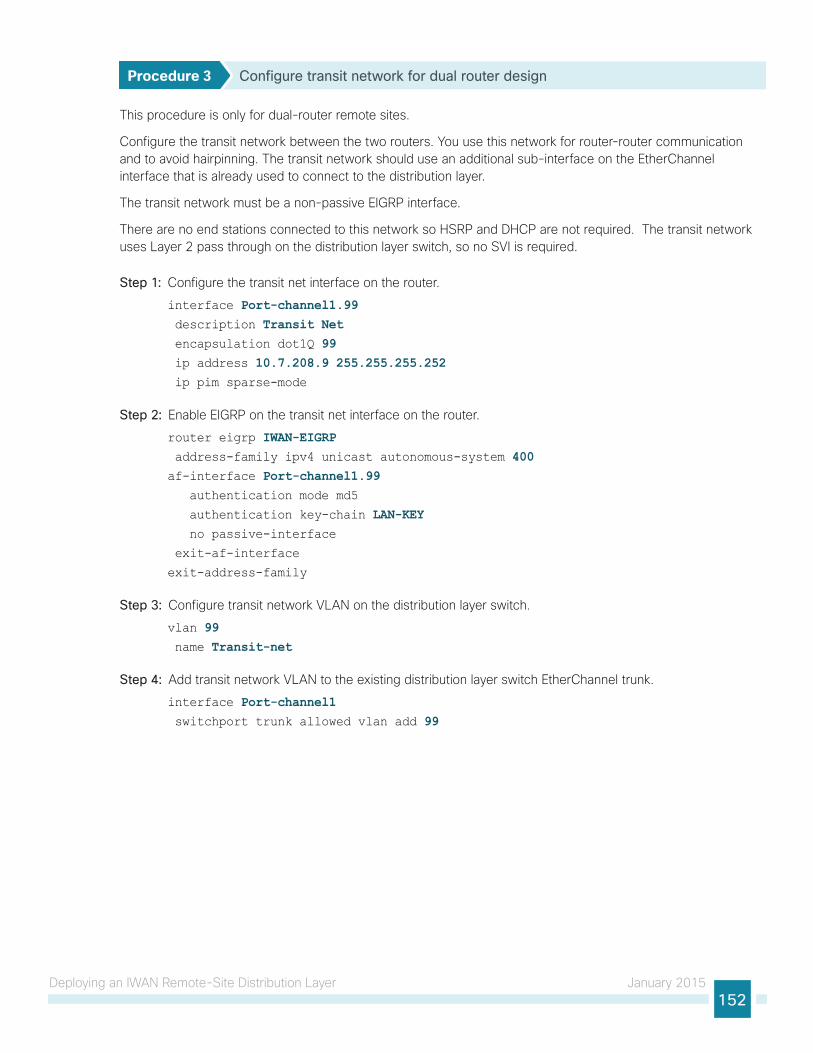
Deploying an IWAN Remote-Site Distribution Layer January 2015152
Procedure 3 Configure transit network for dual router design
This procedure is only for dual-router remote sites.
Configure the transit network between the two routers. You use this network for router-router communication and to avoid hairpinning. The transit network should use an additional sub-interface on the EtherChannel interface that is already used to connect to the distribution layer.
The transit network must be a non-passive EIGRP interface.
There are no end stations connected to this network so HSRP and DHCP are not required. The transit network uses Layer 2 pass through on the distribution layer switch, so no SVI is required.
Step 1: Configure the transit net interface on the router.
interface Port-channel1.99 description Transit Net encapsulation dot1Q 99 ip address 10.7.208.9 255.255.255.252 ip pim sparse-mode
Step 2: Enable EIGRP on the transit net interface on the router.
router eigrp IWAN-EIGRP address-family ipv4 unicast autonomous-system 400af-interface Port-channel1.99 authentication mode md5
authentication key-chain LAN-KEY no passive-interface
exit-af-interface
exit-address-family
Step 3: Configure transit network VLAN on the distribution layer switch.
vlan 99 name Transit-net
Step 4: Add transit network VLAN to the existing distribution layer switch EtherChannel trunk.
interface Port-channel1 switchport trunk allowed vlan add 99

Deploying an IWAN Remote-Site Distribution Layer January 2015153
Connecting Remote-Site Router to Distribution Layer (Router 2)
1. Connect router to distribution layer
2. Configure EIGRP for distribution layer linkPR
OC
ESS
This process helps you configure a DMVPN spoke router for an IWAN remote site and connect to a distribution layer.
This process covers the IWAN hybrid design model and the IWAN dual-Internet design model. Use this process to connect a distribution layer to the second router of the dual-router, dual-link design.
The dual-router distribution layer remote-site option is shown in the following figure.
Figure 29 - WAN remote site: Connection to distribution layer
VLAN 50 - Router 1 Link
802.1q Trunk(xx-xx)
802.1q Trunk(xx-xx)
802.1q Trunk(50, 99)
802.1q Trunk(54, 99)
VLAN 54 - Router 2 LinkVLAN 99 - Transit 1
22
3
Procedure 1 Connect router to distribution layer
Please refer to the Campus Wired LAN Design Guide for complete distribution layer configuration details. This guide only includes the additional steps to complete the distribution layer configuration.
Reader Tip

Deploying an IWAN Remote-Site Distribution Layer January 2015154
Layer 2 EtherChannels are used to interconnect the remote-site router to the distribution layer in the most resilient method possible. This connection allows for multiple VLANs to be included on the EtherChannel as necessary.
Step 1: Configure port-channel interface on the router.
interface Port-channel2 description EtherChannel link to RS42-D3850 no shutdown
Step 2: Configure the port channel sub-interfaces and assign IP address.
After you have enabled the interface, map the appropriate sub-interfaces to the VLANs on the distribution layer switch. The sub-interface number does not need to equate to the 802.1Q tag, but making them the same simplifies the overall configuration.
The sub-interface configured on the router corresponds to a VLAN interface on the distribution-layer switch. Traffic is routed between the devices with the VLAN acting as a point-to-point link.
interface Port-channel2.54 description R2 routed link to distribution layer encapsulation dot1Q 54 ip address 10.7.208.5 255.255.255.252 ip pim sparse-mode
Step 3: Configure the transit network interface on the router.
interface Port-channel2.99 description Transit Net encapsulation dot1Q 99 ip address 10.7.208.10 255.255.255.252 ip pim sparse-mode
Step 4: Configure EtherChannel member interfaces on the router.
Configure the physical interfaces to tie to the logical port-channel using the channel-group command. The number for the port-channel and channel-group must match. Not all router platforms can support LACP to negotiate with the switch, so EtherChannel is configured statically.
interface GigabitEthernet0/0/2 description RS42-D3850X Gig1/1/2
interface GigabitEthernet0/0/3 description RS42-D3850X Gig2/1/2
interface range GigabitEthernet0/0/2, GigabitEthernet0/0/3 no ip address
channel-group 2 no shutdown
Step 5: Configure VLAN on the distribution layer switch.
vlan 54 name R2-link
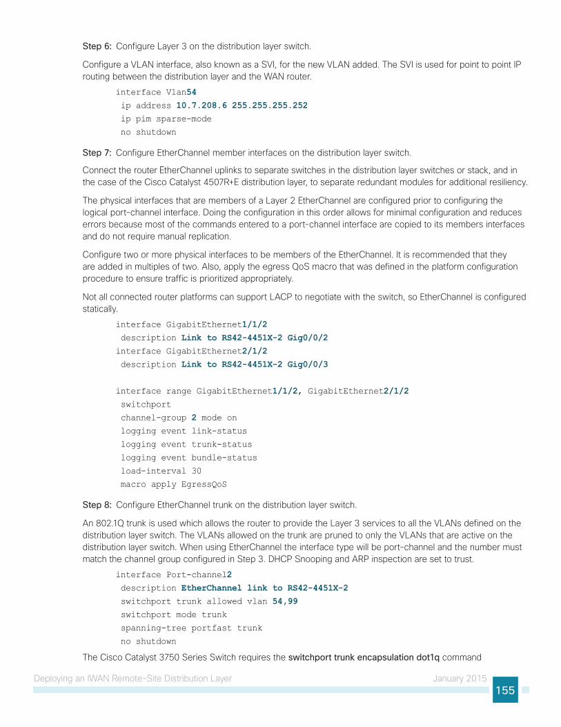
Deploying an IWAN Remote-Site Distribution Layer January 2015155
Step 6: Configure Layer 3 on the distribution layer switch.
Configure a VLAN interface, also known as a SVI, for the new VLAN added. The SVI is used for point to point IP routing between the distribution layer and the WAN router.
interface Vlan54 ip address 10.7.208.6 255.255.255.252 ip pim sparse-mode
no shutdown
Step 7: Configure EtherChannel member interfaces on the distribution layer switch.
Connect the router EtherChannel uplinks to separate switches in the distribution layer switches or stack, and in the case of the Cisco Catalyst 4507R+E distribution layer, to separate redundant modules for additional resiliency.
The physical interfaces that are members of a Layer 2 EtherChannel are configured prior to configuring the logical port-channel interface. Doing the configuration in this order allows for minimal configuration and reduces errors because most of the commands entered to a port-channel interface are copied to its members interfaces and do not require manual replication.
Configure two or more physical interfaces to be members of the EtherChannel. It is recommended that they are added in multiples of two. Also, apply the egress QoS macro that was defined in the platform configuration procedure to ensure traffic is prioritized appropriately.
Not all connected router platforms can support LACP to negotiate with the switch, so EtherChannel is configured statically.
interface GigabitEthernet1/1/2 description Link to RS42-4451X-2 Gig0/0/2interface GigabitEthernet2/1/2 description Link to RS42-4451X-2 Gig0/0/3
interface range GigabitEthernet1/1/2, GigabitEthernet2/1/2 switchport
channel-group 2 mode on logging event link-status
logging event trunk-status
logging event bundle-status
load-interval 30
macro apply EgressQoS
Step 8: Configure EtherChannel trunk on the distribution layer switch.
An 802.1Q trunk is used which allows the router to provide the Layer 3 services to all the VLANs defined on the distribution layer switch. The VLANs allowed on the trunk are pruned to only the VLANs that are active on the distribution layer switch. When using EtherChannel the interface type will be port-channel and the number must match the channel group configured in Step 3. DHCP Snooping and ARP inspection are set to trust.
interface Port-channel2 description EtherChannel link to RS42-4451X-2 switchport trunk allowed vlan 54,99 switchport mode trunk
spanning-tree portfast trunk
no shutdown
The Cisco Catalyst 3750 Series Switch requires the switchport trunk encapsulation dot1q command
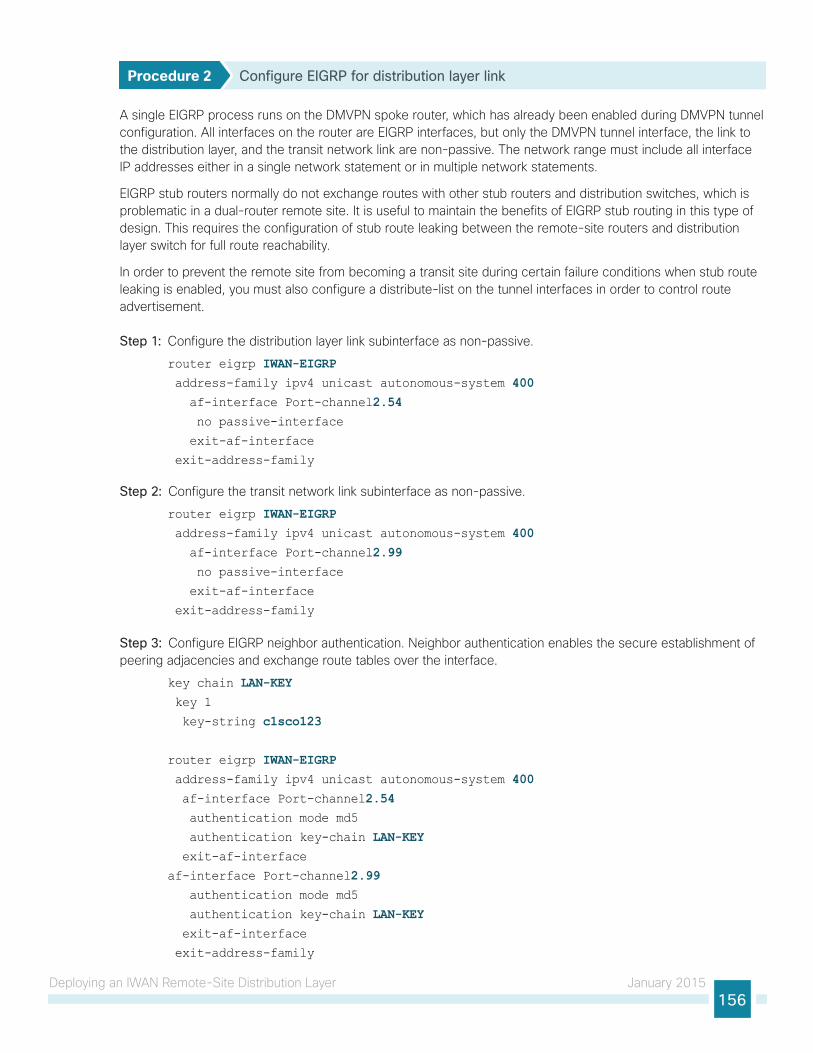
Deploying an IWAN Remote-Site Distribution Layer January 2015156
Procedure 2 Configure EIGRP for distribution layer link
A single EIGRP process runs on the DMVPN spoke router, which has already been enabled during DMVPN tunnel configuration. All interfaces on the router are EIGRP interfaces, but only the DMVPN tunnel interface, the link to the distribution layer, and the transit network link are non-passive. The network range must include all interface IP addresses either in a single network statement or in multiple network statements.
EIGRP stub routers normally do not exchange routes with other stub routers and distribution switches, which is problematic in a dual-router remote site. It is useful to maintain the benefits of EIGRP stub routing in this type of design. This requires the configuration of stub route leaking between the remote-site routers and distribution layer switch for full route reachability.
In order to prevent the remote site from becoming a transit site during certain failure conditions when stub route leaking is enabled, you must also configure a distribute-list on the tunnel interfaces in order to control route advertisement.
Step 1: Configure the distribution layer link subinterface as non-passive.
router eigrp IWAN-EIGRP address-family ipv4 unicast autonomous-system 400 af-interface Port-channel2.54 no passive-interface
exit-af-interface
exit-address-family
Step 2: Configure the transit network link subinterface as non-passive.
router eigrp IWAN-EIGRP address-family ipv4 unicast autonomous-system 400 af-interface Port-channel2.99 no passive-interface
exit-af-interface
exit-address-family
Step 3: Configure EIGRP neighbor authentication. Neighbor authentication enables the secure establishment of peering adjacencies and exchange route tables over the interface.
key chain LAN-KEY key 1
key-string c1sco123
router eigrp IWAN-EIGRP address-family ipv4 unicast autonomous-system 400 af-interface Port-channel2.54 authentication mode md5
authentication key-chain LAN-KEY exit-af-interface
af-interface Port-channel2.99 authentication mode md5
authentication key-chain LAN-KEY exit-af-interface
exit-address-family
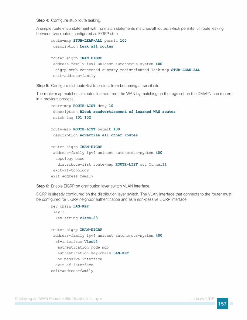
Deploying an IWAN Remote-Site Distribution Layer January 2015157
Step 4: Configure stub route leaking.
A simple route-map statement with no match statements matches all routes, which permits full route leaking between two routers configured as EIGRP stub.
route-map STUB-LEAK-ALL permit 100 description Leak all routes
router eigrp IWAN-EIGRP address-family ipv4 unicast autonomous-system 400 eigrp stub connected summary redistributed leak-map STUB-LEAK-ALL exit-address-family
Step 5: Configure distribute-list to protect from becoming a transit site.
The route-map matches all routes learned from the WAN by matching on the tags set on the DMVPN hub routers in a previous process.
route-map ROUTE-LIST deny 10 description Block readvertisement of learned WAN routes match tag 101 102
route-map ROUTE-LIST permit 100 description Advertise all other routes
router eigrp IWAN-EIGRP address-family ipv4 unicast autonomous-system 400 topology base
distribute-list route-map ROUTE-LIST out Tunnel11 exit-af-topology
exit-address-family
Step 6: Enable EIGRP on distribution layer switch VLAN interface.
EIGRP is already configured on the distribution layer switch. The VLAN interface that connects to the router must be configured for EIGRP neighbor authentication and as a non-passive EIGRP interface.
key chain LAN-KEY key 1
key-string c1sco123
router eigrp IWAN-EIGRP address-family ipv4 unicast autonomous-system 400 af-interface Vlan54 authentication mode md5
authentication key-chain LAN-KEY no passive-interface
exit-af-interface
exit-address-family

Deploying IWAN Quality of Service January 2015158
Deploying IWAN Quality of Service
QoS has already proven itself as the enabling technology for the convergence of voice, video and data networks. As business needs evolve, so do demands on QoS technologies. The need to protect voice, video and critical data with QoS mechanisms is extremely important on the WAN because access speeds are much lower than the LAN networks that feed them.
Configuring QoS for DMVPN Routers
1. Create the class maps in order to classify traffic
2. Create policy map with queuing policy
PR
OC
ESS
When configuring WAN-edge QoS, you are defining how traffic egresses your network. It is critical that the classification, marking, and bandwidth allocations align to the service provider, offering to ensure consistent QoS treatment end to end.
The Per-Tunnel QoS for DMVPN feature allows the configuration of a QoS policy on a DMVPN hub on a per-tunnel (spoke) basis. The QoS policy on a tunnel instance allows you to shape the tunnel traffic to individual spokes (parent policy) and to differentiate between traffic classes within the tunnel for appropriate treatment (child policy).
You can also mark the header of the GRE tunneled packets by using the QoS policy map classes. There are two methods for marking the DSCP of the tunnel headers in order to influence per-hop treatment within the service provider network. One method applies the policy to a virtual tunnel interface and the second method applies the policy to a physical interface.
The following table shows an example of how to mark the tunnel headers when using a 12 or 8-class model in the enterprise, while combining the traffic classes into a smaller 6-, 5- or 4-class model in the service provider network. The tunnel markings must match the service provider offering, so you will have to adjust the table below according to your specific service level agreement.

Deploying IWAN Quality of Service January 2015159
Figure 30 - QoS class model mapping: Tunnel mappings must match provider
Because the provider will generally have a network control queue that they do not declare as part of their customer-facing model, the traffic in the NET-CTRL-MGMT queue will be marked as CS6 on the tunnel header Because the network elements use this traffic to ensure stability under congestion and when a device is oversubscribed, CS6 traffic should be preserved.
Tech Tip
Traffic is regulated from the central site (hub) routers to the remote-site routers on a per-tunnel (spoke) basis. The hub site is unable to send more traffic than a single remote-site can handle, and this ensures that high bandwidth hub sites do not overrun lower bandwidth remote-sites.
The following two procedures apply to all DMVPN WAN hub and spoke routers.
Procedure 1 Create the class maps in order to classify traffic
This number of classes in an egress policy should be chosen based on interface speed, available queues, and device capabilities. This design guide uses an 8-class model in the enterprise and the examples will have to be modified for other models, as required.
Use the class-map command to define a traffic class and identify traffic to associate with the class name. You use these class names when configuring policy maps that define actions you want to take against the traffic type. The class-map command sets the match logic. In this case, the match-any keyword indicates that the maps match any of the specified criteria. This keyword is followed by the name you want to assign to the class of service. After you have configured the class-map command, you define specific values, such as DSCP and protocols to match with the match command.

Deploying IWAN Quality of Service January 2015160
Step 1: Create the class maps for DSCP matching.
Repeat this step to create a class-map for each of the seven non-default WAN classes of service listed in the following table.
You do not need to explicitly configure the default class.
class-map match-any [class-map name] match dscp [dcsp value] [optional additional dscp value(s)]
Table 59 - Class of service for 8-class model
Class Name Traffic type DSCP values
VOICE Voice traffic ef
INTERACTIVE-VIDEO Interactive video (video conferencing) cs4, af4
STREAMING-VIDEO Video streaming af3
NET-CTRL-MGMT Routing protocols, network management traffic cs6, cs2
CALL-SIGNALING Voice and video call signaling cs3
CRITICAL-DATA Highly interactive af1, af2
default Best effort all others
SCAVENGER Scavenger cs1
Example: Class Maps for 8-class QoS modelclass-map match-any VOICE match dscp efclass-map match-any INTERACTIVE-VIDEO match dscp cs4, af41 af42class-map match-any STREAMING-VIDEO match dscp af31 af32class-map match-any NET-CTRL-MGMT match dscp cs6 cs2class-map match-any CALL-SIGNALING match dscp cs3class-map match-any CRITICAL-DATA match dscp af11 af21class-map match-any SCAVENGER match dscp cs1
You do not need to configure a Best-Effort class-map. This is implicitly included within class-default as shown in Procedure 2.
Tech Tip

Deploying IWAN Quality of Service January 2015161
Procedure 2 Create policy map with queuing policy
The WAN policy map references the class names you created in the previous procedures and defines the queuing behavior, along with the minimum guaranteed bandwidth allocated to each class. Using a policy-map accomplishes this specification. Then, each class within the policy map invokes an egress queue and assigns a percentage of bandwidth. One additional default class defines the minimum allowed bandwidth available for best effort traffic. There are two methods for marking the tunnel headers depending on whether you apply the policy to a virtual tunnel interface or a physical interface.
The local router policy maps define eight classes, while most service providers offer only six classes of service. The NET-CTRL-MGMT class is defined to ensure the correct classification, marking, and queuing of network-critical traffic on egress to the WAN. After the traffic has been transmitted to the service provider, it is put into a queue that is not part of the customer-facing class model.
Tech Tip
Step 1: Create the policy map.
policy-map [policy-map-name]
Step 2: Apply the previously created class-map.
class [class-name]
Step 3: (Optional) Define what proportion of available bandwidth should be reserved for this class of traffic under congestion.
bandwidth remaining percent [percentage]
Step 4: (Optional) Define the congestion avoidance mechanism.
random-detect [type]
Step 5: (Optional) For priority queues, define the priority level for the class
priority level [value]
Step 6: (Optional) For priority queues, define the amount of bandwidth that may be consumed by priority traffic.
police cir [percentage]
Step 7: (Optional) For QOS policies that will be attached to tunnel interfaces (hub router configuration), mark the DSCP in the tunnel header.
set dscp tunnel [dscp value]
Step 8: (Optional) For QOS policies that will be attached to physical interface (remote-site router configuration), mark the DSCP in the tunnel header.
set dscp [dscp value]
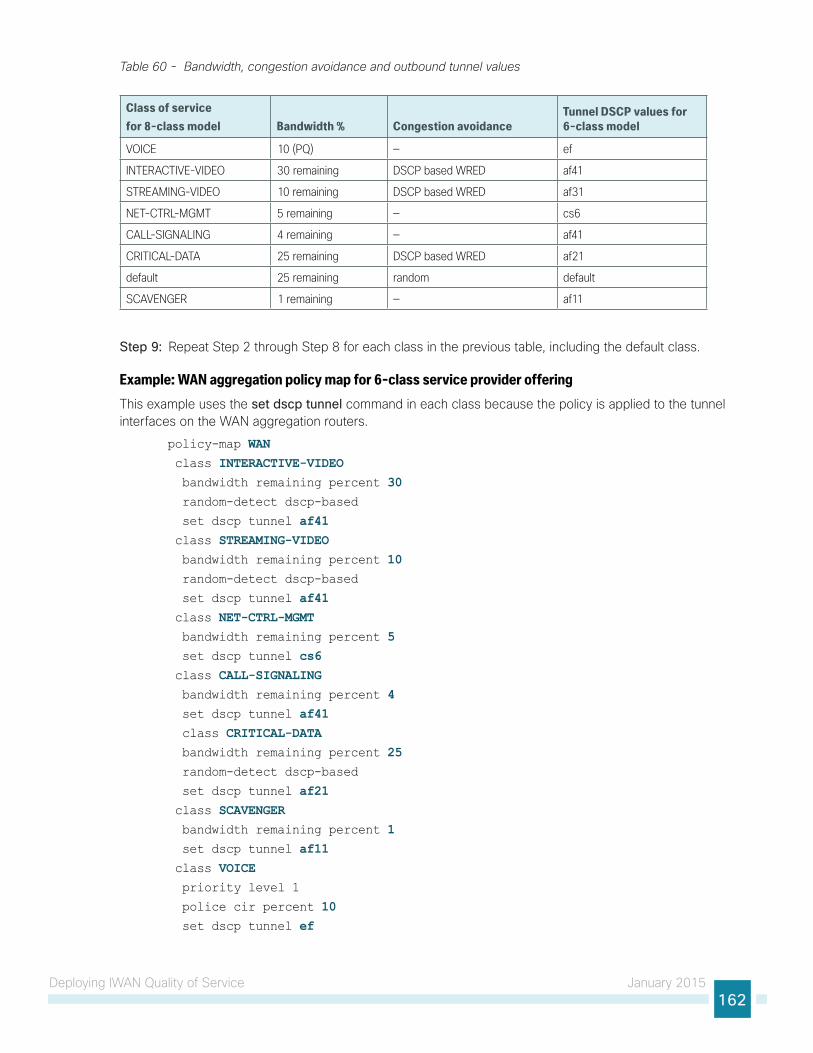
Deploying IWAN Quality of Service January 2015162
Table 60 - Bandwidth, congestion avoidance and outbound tunnel values
Class of service for 8-class model Bandwidth % Congestion avoidance
Tunnel DSCP values for 6-class model
VOICE 10 (PQ) — ef
INTERACTIVE-VIDEO 30 remaining DSCP based WRED af41
STREAMING-VIDEO 10 remaining DSCP based WRED af31
NET-CTRL-MGMT 5 remaining — cs6
CALL-SIGNALING 4 remaining — af41
CRITICAL-DATA 25 remaining DSCP based WRED af21
default 25 remaining random default
SCAVENGER 1 remaining — af11
Step 9: Repeat Step 2 through Step 8 for each class in the previous table, including the default class.
Example: WAN aggregation policy map for 6-class service provider offeringThis example uses the set dscp tunnel command in each class because the policy is applied to the tunnel interfaces on the WAN aggregation routers.
policy-map WAN class INTERACTIVE-VIDEO bandwidth remaining percent 30 random-detect dscp-based
set dscp tunnel af41 class STREAMING-VIDEO bandwidth remaining percent 10 random-detect dscp-based
set dscp tunnel af41 class NET-CTRL-MGMT bandwidth remaining percent 5 set dscp tunnel cs6 class CALL-SIGNALING bandwidth remaining percent 4 set dscp tunnel af41 class CRITICAL-DATA bandwidth remaining percent 25 random-detect dscp-based
set dscp tunnel af21 class SCAVENGER bandwidth remaining percent 1 set dscp tunnel af11 class VOICE priority level 1
police cir percent 10 set dscp tunnel ef

Deploying IWAN Quality of Service January 2015163
class class-default bandwidth remaining percent 25 random-detect
set dscp tunnel default
Example: Remote site policy map for 6-class service provider offeringThis example uses the set dscp command in each class, because the policy is applied to the physical interfaces on the remote site routers.
policy-map WANclass INTERACTIVE-VIDEO bandwidth remaining percent 30 random-detect dscp-based
set dscp af41class STREAMING-VIDEO bandwidth remaining percent 10 random-detect dscp-based
set dscp af41 class NET-CTRL-MGMT bandwidth remaining percent 5 set dscp cs6 class CALL-SIGNALING bandwidth remaining percent 4 set dscp af41 class CRITICAL-DATA bandwidth remaining percent 25 random-detect dscp-based
set dscp af21 class SCAVENGER bandwidth remaining percent 1 set dscp af11 class VOICE priority level 1
police cir percent 10 set dscp ef class class-default bandwidth remaining percent 25 random-detect
set dscp default
Although these bandwidth assignments represent a good baseline, it is important to consider your actual traffic requirements per class and adjust the bandwidth settings accordingly.
Tech Tip

Deploying IWAN Quality of Service January 2015164
Applying DMVPN QoS Policy to DMVPN Hub Routers
1. Configure shaping policy for hub router
2. Configure per-tunnel QoS policies for DMVPN hub router
3. Configure per-tunnel QoS NHRP policies on DMVPN hub routerPR
OC
ESS
This process applies only to DMVPN WAN Aggregation routers.
Procedure 1 Configure shaping policy for hub router
With WAN interfaces using Ethernet as an access technology, the demarcation point between the enterprise and service provider may no longer have a physical-interface bandwidth constraint. Instead, a specified amount of access bandwidth is contracted with the service provider. To ensure the offered load to the service provider does not exceed the contracted rate that results in the carrier discarding traffic, you need to configure shaping on the physical interface. When you configure the shape average command, ensure that the value matches the contracted bandwidth rate from your service provider.
QoS on a physical interface is limited only to the class default shaper. Other QoS configurations on the physical interface are not supported.
You must apply the class default shaper policy map on the main interface before applying the tunnel policy map.
The class default shaper policy map must contain only the class class-default and shape commands.
Tech Tip
Create the policy map and configure the shaper for the default class.
As a best practice, embed the interface name within the name of the policy map.
policy-map [policy-map-name] class class-default shape average [bandwidth (kbps)]
Step 1: Apply the shaper to the WAN interface.
You must apply the service policy needs to be applied in the outbound direction.
interface [interface type] [number] service-policy output [policy-map-name]

Deploying IWAN Quality of Service January 2015165
Example: Physical interfaceThis example shows a router with a 100 Mbps service rate configured on a 1 Gbps physical interface.
policy-map WAN-INTERFACE-G0/0/3-SHAPE-ONLY class class-default shape average 100000000 interface GigabitEthernet0/0/3 bandwidth 100000 service-policy output WAN-INTERFACE-G0/0/3-SHAPE-ONLY
Procedure 2 Configure per-tunnel QoS policies for DMVPN hub router
The QoS policy on a tunnel instance allows you to shape the tunnel traffic to individual spokes and to differentiate between traffic classes within the tunnel for appropriate treatment.
The QoS policy on the tunnel instance is defined and applied only to the DMVPN hub routers at the central site. The remote-site router signals the QoS group policy information to the hub router with a command in the NHRP configuration, which greatly reduces QoS configuration and complexity. The hub router applies the signaled policy in the egress direction for each remote site.
With Per-Tunnel QoS for DMVPN, the queuing and shaping is performed at the outbound physical interface for the GRE/IPsec tunnel packets. This means that the GRE header, the IPsec header and the layer2 (for the physical interface) header are included in the packet-size calculations for shaping and bandwidth queuing of packets under QoS.
The values in the table are examples; make sure to adjust these values for your specific needs and remote-site bandwidth provisioned with your ISP.
Tech Tip
Table 61 - Per-Tunnel QoS policies
Policy Name Class Bandwidth bps
RS-GROUP-300MBPS-POLICY class-default 300000000
RS-GROUP-200MBPS-POLICY class-default 200000000
RS-GROUP-100MBPS-POLICY class-default 100000000
RS-GROUP-50MBPS-POLICY class-default 50000000
RS-GROUP-30MBPS-POLICY class-default 30000000
RS-GROUP-20MBPS-POLICY class-default 20000000
RS-GROUP-10MBPS-POLICY class-default 10000000
RS-GROUP-4G-POLICY class-default 8000000
Step 1: Create a policy.
policy-map [policy-map-name]

Deploying IWAN Quality of Service January 2015166
Step 2: Define a shaper and bandwidth remaining ratio for the default-class and apply the WAN QoS queuing child service policy created in Procedure 2, “Define policy map to use queuing policy.”
policy-map [policy-map-name] class class-default shape average [bandwidth (kbps)] bandwidth remaining ratio [bandwidth / 1 Mbps] service-policy [policy-map name]
Step 3: For each remote-site type, repeat steps 1 and 2.
Example: Hub routerpolicy-map RS-GROUP-300MBPS-POLICY class class-default
shape average 300000000 bandwidth remaining ratio 300 service-policy WANpolicy-map RS-GROUP-200MBPS-POLICY class class-default
shape average 200000000 bandwidth remaining ratio 200 service-policy WANpolicy-map RS-GROUP-100MBPS-POLICY class class-default
shape average 100000000 bandwidth remaining ratio 100 service-policy WANpolicy-map RS-GROUP-50MBPS-POLICY class class-default
shape average 50000000 bandwidth remaining ratio 50 service-policy WANpolicy-map RS-GROUP-30MBPS-POLICY class class-default
bandwidth remaining ratio 30 shape average 30000000 service-policy WANpolicy-map RS-GROUP-20MBPS-POLICY class class-default
shape average 20000000 bandwidth remaining ratio 20 service-policy WANpolicy-map RS-GROUP-10MBPS-POLICY class class-default
shape average 10000000 bandwidth remaining ratio 10 service-policy WANpolicy-map RS-GROUP-4G-POLICY

Deploying IWAN Quality of Service January 2015167
class class-default
shape average 8000000 bandwidth remaining ratio 8 service-policy WAN
Procedure 3 Configure per-tunnel QoS NHRP policies on DMVPN hub router
The QoS policy that the hub uses for a particular endpoint or spoke is selected by the NHRP group in which the spoke is configured.
Prerequisites and important caveats:
• DMVPN must be fully configured and operational before you can configure an NHRP group on a spoke or map the NHRP group to a QoS policy on a hub.
• Although you may configure multiple spokes as part of the same NHRP group, the tunnel traffic for each spoke is measured individually for shaping and policing.
• Only output NHRP policies are supported. These apply to per-site traffic egressing the router towards the WAN.
Step 1: Create NHRP group policy name mapping and apply the policies configured in the previous procedure to the DMVPN tunnel interface on the hub router.
interface tunnel[number] ip nhrp map group [NHRP GROUP Policy Name] service-policy output [policy-map name]
Example: Hub routerinterface tunnel10 ip nhrp map group RS-GROUP-300MBPS service-policy output RS-GROUP-300MBPS-POLICY ip nhrp map group RS-GROUP-200MBPS service-policy output RS-GROUP-200MBPS-POLICY ip nhrp map group RS-GROUP-100MBPS service-policy output RS-GROUP-100MBPS-POLICY ip nhrp map group RS-GROUP-50MBPS service-policy output RS-GROUP-50MBPS-POLICY ip nhrp map group RS-GROUP-30MBPS service-policy output RS-GROUP-30MBPS-POLICY ip nhrp map group RS-GROUP-20MBPS service-policy output RS-GROUP-20MBPS-POLICY ip nhrp map group RS-GROUP-10MBPS service-policy output RS-GROUP-10MBPS-POLICY ip nhrp map group RS-GROUP-4G service-policy output RS-GROUP-4G-POLICY

Deploying IWAN Quality of Service January 2015168
Applying QoS Configurations to Remote Site Routers
1. Configure per-tunnel QoS NHRP policy on remote-site routers
2. Configure physical interface QoS policy on remote-site routers
3. Apply QoS policy to the physical interface on remote-site routers
4. Verify QoS policy on physical interfaces of remote site router
5. Verify DMVPN per-tunnel QoS from hub routers
PR
OC
ESS
This process completes the remote-site QoS configuration and applies to all DMVPN spoke routers.
Procedure 1 Configure per-tunnel QoS NHRP policy on remote-site routers
This procedure configures the remote-site router to reference the QoS policy configured on the hub site routers.
Step 1: Apply the NHRP group policy to the DMVPN tunnel interface on the corresponding remote-site router. Use the NHRP group name as defined on the hub router in Procedure 2, “Configure per-tunnel QoS policies for DMVPN hub router,” above.
interface Tunnel[value] ip nhrp group [NHRP GROUP Policy Name]
Example: Remote-site router with dual-linkThis example shows a remote-site using a 20 Mbps policy and a 10 Mbps policy.
interface Tunnel10 ip nhrp group RS-GROUP-20MBPS
interface Tunnel11 ip nhrp group RS-GROUP-10MBPS
Procedure 2 Configure physical interface QoS policy on remote-site routers
Repeat this procedure in order to support remote-site routers that have multiple WAN connections attached to different interfaces.
With WAN interfaces using Ethernet as an access technology, the demarcation point between the enterprise and service provider may no longer have a physical-interface bandwidth constraint. Instead, a specified amount of access bandwidth is contracted with the service provider. To ensure the offered load to the service provider does not exceed the contracted rate that results in the carrier discarding traffic, configure shaping on the physical interface. This shaping is accomplished with a QoS service policy. You configure a QoS service policy on the outside Ethernet interface, and this parent policy includes a shaper that then references a second or subordinate (child) policy that enables queuing within the shaped rate. This is called a hierarchical Class-Based Weighted Fair Queuing configuration. When you configure the shape average command, ensure that the value matches the contracted bandwidth rate from your service provider.

Deploying IWAN Quality of Service January 2015169
Step 1: Create the parent policy map.
As a best practice, embed the interface name within the name of the parent policy map.
policy-map [policy-map-name]
Step 2: Configure the shaper.
class [class-name] shape [average | peak] [bandwidth (kbps)]
Step 3: Apply the child service policy as defined in Procedure 2, “Define policy map to use queuing policy,” above.
service-policy WAN
Example: Remote-site router with dual-linkThis example shows a router with a 20-Mbps rate on interface GigabitEthernet0/0 and a 10-Mbps rate on interface GigabitEthernet0/1.
policy-map WAN-INTERFACE-G0/0 class class-default shape average 20000000 service-policy WAN
policy-map WAN-INTERFACE-G0/1 class class-default shape average 10000000 service-policy WAN
Procedure 3 Apply QoS policy to the physical interface on remote-site routers
Repeat this procedure in order to support remote-site routers that have multiple WAN connections attached to different interfaces.
To invoke shaping and queuing on a physical interface, you must apply the parent policy that you configured in the previous procedure.
Step 1: Select the WAN interface.
interface [interface type] [number]
Step 2: Apply the WAN QoS policy.
The service policy needs to be applied in the outbound direction.
service-policy output [policy-map-name]
Example: Remote-site router with dual-linkinterface GigabitEthernet0/0 service-policy output WAN-INTERFACE-G0/0
interface GigabitEthernet0/1 service-policy output WAN-INTERFACE-G0/1

Deploying IWAN Quality of Service January 2015170
Procedure 4 Verify QoS policy on physical interfaces of remote site router
After all of the physical interfaces on a router are configured, you can verify each one before moving to the next remote site.
Step 1: Verify the QoS output policy on each interface is correct by using the show policy-map interface command.
This example is truncated due to the overall length.
RS11-2921# show policy-map interface GigabitEthernet 0/0GigabitEthernet0/0
Service-policy output: WAN-INTERFACE-G0/0
Class-map: class-default (match-any)
66941984 packets, 14951533762 bytes
5 minute offered rate 83000 bps, drop rate 0000 bps
Match: any
Queueing
queue limit 64 packets
(queue depth/total drops/no-buffer drops) 0/0/0
(pkts output/bytes output) 66941987/15813338284
shape (average) cir 30000000, bc 120000, be 120000
target shape rate 30000000
Service-policy : WAN
queue stats for all priority classes:
Queueing
priority level 1
queue limit 64 packets
(queue depth/total drops/no-buffer drops) 0/0/0
(pkts output/bytes output) 572961/124080310
Class-map: INTERACTIVE-VIDEO (match-any)
530608 packets, 205927572 bytes
5 minute offered rate 0000 bps, drop rate 0000 bps
Match: dscp cs4 (32) af41 (34) af42 (36)
530608 packets, 205927572 bytes
5 minute rate 0 bps
Queueing
queue limit 64 packets
(queue depth/total drops/no-buffer drops) 0/0/0
(pkts output/bytes output) 530608/209102464
bandwidth remaining 30%
Exp-weight-constant: 9 (1/512)
Mean queue depth: 0 packets

Deploying IWAN Quality of Service January 2015171
dscp Transmitted Random drop Tail drop
Minimum Maximum Mark
pkts/bytes pkts/bytes pkts/bytes
thresh thresh prob
af41 530608/209102464 0/0 0/0
32 40 1/10
QoS Set
dscp af41
Packets marked 530608
Step 2: Repeat the previous step for each interface configured with QoS.
Procedure 5 Verify DMVPN per-tunnel QoS from hub routers
Once the all of the DMVPN routers are configured for Per-Tunnel QoS, you can verify the configurations from the hub router.
Step 1: Verify the Per-Tunnel QoS output policy to each remote-site is correct by using the show dmvpn detail command.
This example is truncated due to the overall length.
VPN-MPLS-ASR1002X-1# show dmvpn detailLegend: Attrb --> S - Static, D - Dynamic, I - Incomplete
N - NATed, L - Local, X - No Socket
T1 - Route Installed, T2 - Nexthop-override
C - CTS Capable
# Ent --> Number of NHRP entries with same NBMA peer
NHS Status: E --> Expecting Replies, R --> Responding, W --> Waiting
UpDn Time --> Up or Down Time for a Tunnel
==========================================================================
Interface Tunnel10 is up/up, Addr. is 10.6.34.1, VRF ""
Tunnel Src./Dest. addr: 192.168.6.1/MGRE, Tunnel VRF "IWAN-TRANSPORT-1"
Protocol/Transport: "multi-GRE/IP", Protect "DMVPN-PROFILE-TRANSPORT-1"
Interface State Control: Disabled
nhrp event-publisher : Disabled
Type:Hub, Total NBMA Peers (v4/v6): 9
# Ent Peer NBMA Addr Peer Tunnel Add State UpDn Tm Attrb Target Network
----- --------------- --------------- ----- -------- ----- -----------------
1 192.168.6.5 10.6.34.11 UP 1w0d D 10.6.34.11/32
NHRP group: RS-GROUP-30MBPS
Output QoS service-policy applied: RS-GROUP-30MBPS-POLICY
1 192.168.6.9 10.6.34.12 UP 1w0d D 10.6.34.12/32

Deploying IWAN Quality of Service January 2015172
NHRP group: RS-GROUP-20MBPS
Output QoS service-policy applied: RS-GROUP-20MBPS-POLICY
1 192.168.6.13 10.6.34.21 UP 1w0d D 10.6.34.21/32
NHRP group: RS-GROUP-30MBPS
Output QoS service-policy applied: RS-GROUP-30MBPS-POLICY
1 192.168.6.17 10.6.34.22 UP 1w0d D 10.6.34.22/32
NHRP group: RS-GROUP-20MBPS
Output QoS service-policy applied: RS-GROUP-20MBPS-POLICY
1 192.168.6.21 10.6.34.31 UP 1w0d D 10.6.34.31/32
NHRP group: RS-GROUP-200MBPS
Output QoS service-policy applied: RS-GROUP-200MBPS-POLICY
1 192.168.6.25 10.6.34.32 UP 1w0d D 10.6.34.32/32
NHRP group: RS-GROUP-300MBPS
Output QoS service-policy applied: RS-GROUP-300MBPS-POLICY
1 192.168.6.29 10.6.34.41 UP 1w0d D 10.6.34.41/32
NHRP group: RS-GROUP-30MBPS
Output QoS service-policy applied: RS-GROUP-30MBPS-POLICY
1 192.168.6.33 10.6.34.42 UP 1w0d D 10.6.34.42/32
NHRP group: RS-GROUP-300MBPS
Output QoS service-policy applied: RS-GROUP-300MBPS-POLICY
Step 2: Repeat the previous step for each DMVPN hub router.

Deploying IWAN Performance Routing January 2015173
Deploying IWAN Performance Routing
Performance Routing Version 3 (PfRv3) consists of two major Cisco IOS components, an MC and a BR. The MC defines the policies and applies them to various traffic classes that traverse the BR systems. The MC can be configured to learn and control traffic classes on the network.
• The MC is the policy decision-maker. At a large site, such as a data center or campus, the MC is a standalone router. For smaller locations, the MC is typically collocated (configured) on the same platform as the BR. As a general rule, the large locations manage more network prefixes and applications than a remote site deployment so they consume more CPU and memory resources for the MC function. Therefore, Cisco recommends a dedicated router for the MC at large sites.
• The BR is in the data-forwarding path. A BR collects data from its Performance Monitor cache and smart probes, provides a degree of aggregation of this information, and influences the packet-forwarding path as directed by the MC to optimize traffic.
The remote site typically manages fewer active traffic classes (TCs), which are made up of prefixes and applications. In most remote site deployments, it is possible to co-locate the MC and BR on the same hardware platform. CPU and memory utilization should be monitored on MC platforms, and if utilization is high, the network manager should consider an MC platform with a higher capacity CPU and memory. The MC communicates with the border routers over an authenticated TCP socket but has no requirement for populating its own IP routing table with anything more than a route to reach the border routers.
Because PfRv3 is an intelligent path selection technology, there must be at least two external interfaces under the control of PfRv3 and at least one internal interface. There must be at least one BR configured. If only one BR is configured, then both external interfaces are attached to the single BR. If more than one BR is configured, then the two or more external interfaces are configured across these BR platforms. External links, or exit points, are therefore owned by the BR; they may be logical (tunnel) or physical interfaces (serial, Ethernet, etc.).
There are four different roles a device can play in a PfRv3 configuration:
• Hub Master Controller—The hub MC is the MC at the primary WAN aggregation site. This is the MC device where all PfRv3 policies are configured. It also acts as MC for that site and makes path optimization decision. There is only one hub MC per IWAN domain.
• Hub Border Router—This is a BR at the hub MC site. This is the device where WAN interfaces terminate. There can be one or more WAN interfaces on the same device. There can be one or more hub BRs. On the Hub BRs, PfRv3 must be configured with:
◦ The address of the local MC
◦ The path name on external interfaces
• Branch Master Controller—The Branch MC is the MC at the branch-site. There is no policy configuration on this device. It receives policy from the Hub MC. This device acts as MC for that site for making path optimization decision. The configuration includes the IP address of the hub MC.
• Branch Border Router—This is a BR at the branch-site. The configuration on this device enables BR functionality and includes the IP address of the site local MC. The WAN interface that terminates on the device is detected automatically.

Deploying IWAN Performance Routing January 2015174
The first design model is the IWAN Hybrid, which uses a primary MPLS transport paired with Internet VPN as a secondary transport. In this design model, the MPLS WAN provides SLA class of service guarantees for key applications. The second design model is the IWAN Dual Internet, which uses a pair of Internet service providers to further reduce cost while leveraging PfR in order to mitigate network performance problems on a single Internet provider. The PfR configuration is the same for both design models, so this guide will focus mainly on the IWAN Hybrid design.
The following diagrams show the four different device roles and where the fit into the IWAN Hybrid design model.
Figure 31 - IWAN hybrid design model: PfR hub location
WAN DistributionLayer
Core Layer
DMVPN 2
12
35
DMVPN 1
Internet Edge
INET
Hub BorderRouters
Hub MasterController
MPLS
Figure 32 - IWAN hybrid design model: PfR branch locations1
23
6
MPLS Internet
BranchBorderRouter
Branch MasterController/
BranchBorder Router
Branch Master Controller/
BranchBorder Router
DMVPN 2DMVPN 1
Single Router Location Dual Router Location
MPLS Internet

Deploying IWAN Performance Routing January 2015175
Configuring PfR Hub Master Controller
1. Configure the distribution switch
2. Configure the Hub MC platform
3. Configure connectivity to the LANPR
OC
ESS
This section describes configuring the PfR Hub MC as a new router. Only the core relevant features are included.
Table 62 - Hub MC IP addresses
IWAN Design Model Host name Loopback IP Address Port-channel IP address
Hybrid PFR-MC-ASR-1004-1 10.6.32.251/32 10.6.32.151/26
Dual Internet PFR-MC-ASR-1004-2 10.6.32.252/32 10.6.32.152/26
Procedure 1 Configure the distribution switch
Step 1: If a VLAN does not already exist for the hub MC on the distribution layer switch, configure it now.
vlan 350 name WAN_Service_Net
Step 2: If the Layer 3 SVI has not yet been configured, configure it now.
Be sure to configure a VLAN interface (SVI) for every new VLAN you add, so devices in the VLAN can communicate with the rest of the network.
interface Vlan350 ip address 10.6.32.129 255.255.255.192 no shutdown
Next, configure EtherChannel member interfaces.
EtherChannel is a logical interface that bundles multiple physical LAN links into a single logical link.
Tech Tip
Step 3: Connect the hub MC EtherChannel uplinks in order to separate switches in the distribution layer switches or stack (for the Cisco Catalyst 4507R+E distribution layer, this separates redundant modules for additional resiliency), and then configure two physical interfaces to be members of the EtherChannel. Also, apply the egress QoS macro that was defined in the platform configuration procedure. This ensures traffic is prioritized appropriately. The EtherChannel provides extra resiliency for the hub MC in case there is a link, line card or switch failure.

Deploying IWAN Performance Routing January 2015176
Configure the physical interfaces that are members of a Layer 2 EtherChannel prior to configuring the logical port-channel interface. Doing the configuration in this order allows for minimal configuration and reduces errors because most of the commands entered to a port-channel interface are copied to its members interfaces and do not require manual replication.
Tech Tip
interface GigabitEthernet 1/0/13 description PFR-MC-ASR1004-1 (gig0/0/0)
interface GigabitEthernet 2/0/9 description PFR-MC-ASR1004-1 (gig0/0/1)
interface range GigabitEthernet 1/0/13, GigabitEthernet 2/0/13 switchport
channel-group 21 mode on logging event link-status
logging event bundle-status
load-interval 30 macro apply EgressQoS
Next, configure the EtherChannel. Access mode interfaces are used for the connection to the hub MCs.
Step 4: Assign the VLAN created at the beginning of the procedure to the interface. When using EtherChannel, the port-channel number must match the channel group configured in Step 3.
interface Port-channel 21 description PFR-MC-ASR1004-1 switchport access vlan 350 logging event link-status
load-interval 30 no shutdown
Step 5: Allow the routing protocol to form neighbor relationships across the vlan interface.
router eigrp IWAN-EIGRP address-family ipv4 unicast autonomous-system 400 af-interface Vlan350 no passive-interface
authentication mode md5
authentication key-chain LAN-KEY exit-af-interface
exit-address-family
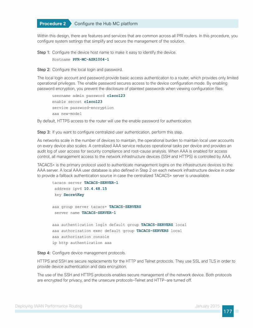
Deploying IWAN Performance Routing January 2015177
Procedure 2 Configure the Hub MC platform
Within this design, there are features and services that are common across all PfR routers. In this procedure, you configure system settings that simplify and secure the management of the solution.
Step 1: Configure the device host name to make it easy to identify the device.
Hostname PFR-MC-ASR1004-1
Step 2: Configure the local login and password.
The local login account and password provide basic access authentication to a router, which provides only limited operational privileges. The enable password secures access to the device configuration mode. By enabling password encryption, you prevent the disclosure of plaintext passwords when viewing configuration files.
username admin password c1sco123enable secret c1sco123service password-encryption
aaa new-model
By default, HTTPS access to the router will use the enable password for authentication.
Step 3: If you want to configure centralized user authentication, perform this step.
As networks scale in the number of devices to maintain, the operational burden to maintain local user accounts on every device also scales. A centralized AAA service reduces operational tasks per device and provides an audit log of user access for security compliance and root-cause analysis. When AAA is enabled for access control, all management access to the network infrastructure devices (SSH and HTTPS) is controlled by AAA.
TACACS+ is the primary protocol used to authenticate management logins on the infrastructure devices to the AAA server. A local AAA user database is also defined in Step 2 on each network infrastructure device in order to provide a fallback authentication source in case the centralized TACACS+ server is unavailable.
tacacs server TACACS-SERVER-1 address ipv4 10.4.48.15 key SecretKey
aaa group server tacacs+ TACACS-SERVERS server name TACACS-SERVER-1
aaa authentication login default group TACACS-SERVERS localaaa authorization exec default group TACACS-SERVERS localaaa authorization console
ip http authentication aaa
Step 4: Configure device management protocols.
HTTPS and SSH are secure replacements for the HTTP and Telnet protocols. They use SSL and TLS in order to provide device authentication and data encryption.
The use of the SSH and HTTPS protocols enables secure management of the network device. Both protocols are encrypted for privacy, and the unsecure protocols—Telnet and HTTP—are turned off.

Deploying IWAN Performance Routing January 2015178
Specify the transport preferred none command on vty lines in order to prevent errant connection attempts from the CLI prompt. Without this command, if the ip name-server is unreachable, long timeout delays may occur for mistyped commands.
ip domain-name cisco.localip ssh version 2
no ip http server
ip http secure-server
ip scp server enable
line vty 0 15
transport input ssh
transport preferred none
Step 5: When synchronous logging of unsolicited messages and debug output is turned on, console log messages are displayed on the console after interactive CLI output is displayed or printed. With this command, you can continue typing at the device console when debugging is enabled.
line con 0
logging synchronous
Step 6: Enable SNMP. This allows the network infrastructure devices to be managed by a NMS. SNMPv2c is configured both for a read-only and a read/write community string.
snmp-server community cisco RO snmp-server community cisco123 RWsnmp-server ifindex persist ! IOS Classic Only
snmp ifmib ifindex persist ! IOS XE Only
Step 7: If operational support is centralized in your network, you can increase network security by using an access list to limit the networks that can access your device. In this example, only devices on the 10.4.48.0/24 network will be able to access the device via SSH or SNMP.
access-list 55 permit 10.4.48.0 0.0.0.255line vty 0 15
access-class 55 in
snmp-server community cisco RO 55 snmp-server community cisco123 RW 55 snmp-server ifindex persist ! IOS Classic Only
snmp ifmib ifindex persist ! IOS XE Only
If you configure an access list on the vty interface, you may lose the ability to use SSH to log in from one router to the next for hop-by-hop troubleshooting.
Tech Tip
Step 8: Configure a synchronized clock.
NTP is designed to synchronize a network of devices. An NTP network usually gets its time from an authoritative time source, such as a radio clock or an atomic clock attached to a time server. NTP then distributes this time across the organization’s network.

Deploying IWAN Performance Routing January 2015179
You should program network devices to synchronize to a local NTP server in the network. The local NTP server typically references a more accurate clock feed from an outside source. By configuring console messages, logs, and debug output to provide time stamps on output, you can cross-reference events in a network.
ntp server 10.4.48.17ntp update-calendar
clock timezone PST -8 clock summer-time PDT recurring service timestamps debug datetime msec localtime
service timestamps log datetime msec localtime
Step 9: Configure an in-band management interface.
The loopback interface is a logical interface that is always reachable as long as the device is powered on and any IP interface is reachable to the network. Because of this capability, the loopback address is the best way to manage the router in-band. Layer 3 process and features are also bound to the loopback interface to ensure process resiliency.
The loopback address is commonly a host address with a 32-bit address mask. Allocate the loopback address from the IP address block that the router summarizes to the rest of the network.
interface Loopback 0
ip address 10.6.32.251 255.255.255.255
Bind the device processes for SNMP, SSH, PIM, TACACS+ and NTP to the loopback interface address for optimal resiliency:
snmp-server trap-source Loopback0
ip ssh source-interface Loopback0
ip pim register-source Loopback0
ip tacacs source-interface Loopback0
ntp source Loopback0
Step 10: Configure IP unicast routing authentication key.
key chain LAN-KEY key 1 key-string c1sco123
Step 11: Configure IP unicast routing using EIGRP named mode.
EIGRP is configured facing the LAN distribution or core layer. In this design, the port-channel interface and the loopback must be EIGRP interfaces. The loopback may remain a passive interface. The network range must include both interface IP addresses, either in a single network statement or in multiple network statements. This design uses a best practice of assigning the router ID to a loopback address.
router eigrp IWAN-EIGRP address-family ipv4 unicast autonomous-system 400 af-interface default
passive-interface
exit-af-interface
network 10.6.0.0 0.1.255.255 eigrp router-id 10.6.32.251 nsf
exit-address-family

Deploying IWAN Performance Routing January 2015180
Procedure 3 Configure connectivity to the LAN
Any links to adjacent distribution layers should be Layer 3 links or Layer 3 EtherChannels.
Step 1: Configure a Layer 3 interface.
interface Port-channel21 ip address 10.6.32.151 255.255.255.192 no shutdown
Step 2: Configure EtherChannel member interfaces.
Configure the physical interfaces to tie to the logical port-channel by using the channel-group command. The number for the port-channel and channel-group must match. Not all router platforms can support LACP to negotiate with the switch, so EtherChannel is configured statically.
interface GigabitEthernet0/0/0 description WAN-D3750X Gig1/0/13
interface GigabitEthernet0/0/1 description WAN-D3750X Gig2/0/13
interface range GigabitEthernet0/0/0, GigabitEthernet0/0/1 no ip address
channel-group 21 no shutdown
Step 3: Configure the EIGRP interface.
Allow EIGRP to form neighbor relationships across the interface to establish peering adjacencies and exchange route tables. In this step, you configure EIGRP authentication by using the authentication key specified in the previous procedure.
router eigrp IWAN-EIGRP address-family ipv4 unicast autonomous-system 400 af-interface Port-channel21 no passive-interface
authentication mode md5
authentication key-chain LAN-KEY exit-af-interface
exit-address-family

Deploying IWAN Performance Routing January 2015181
Configuring Performance Routing for Hub Location
1. Verify IP connectivity to remote site loopback interfaces
2. Configure prefixes for the enterprise and primary site
3. Configure PfR domain in the hub MC
4. Configure PfR domain in the hub BR
5. Verify PfR domain is operational on the hub MC
PR
OC
ESS
All sites belong to an PfR domain where the remote site MCs are peered together. Peering has been greatly enhanced in PfRv3 which allows site information exchange and single touch provisioning.
PfRv3 has simplified policies with pre-existing templates. The policy configuration for the PfR domain is done in the hub MC and the information is distributed to all sites via MC peering. This not only simplifies provisioning substantiall but also makes the policy consistent across the entire IWAN network.
PfRv3 uses Unified Monitor (also called Performance Monitor) to monitor traffic going into WAN links and traffic coming from the WAN links. It monitors performance metrics per differentiated service code point (DSCP) rather than monitoring on per-flow or per-prefix basis. When application-based policies are used, the MC will use a mapping table between the Application Name and the DSCP discovered. This reduces the number of records significantly. PfRv3 relies on performance data measured on the existing data traffic on all paths whenever it can, thereby reducing the need of synthetic traffic. Furthermore, the measurement data is not exported unless there is a violation, which further reduces control traffic and processing of those records.
PfRv3 is also VRF-aware and instances of the MC work under a VRF.
Procedure 1 Verify IP connectivity to remote site loopback interfaces
Cisco recommends using loopback interfaces for the peering traffic between the BR and MC routers. For this design, you put the loopback addresses into a specific subnet range, so they are easily identified in the routing table. The loopback addresses for the remote sites are as follows:
Table 63 - Remote-site loopback IP address ranges
IWAN Design Model Loopback 0 Address Range
Hybrid—Primary Router 10.255.241.0/24
Hybrid—Secondary Router (optional) 10.255.242.0/24
Dual Internet—Primary Router 10.255.243.0/24
Dual Internet—Secondary Router (optional) 10.255.244.0/24

Deploying IWAN Performance Routing January 2015182
Step 1: Verify that the loopback 0 interfaces on each of your remote sites are reachable from the hub MC by using the show ip route command.
This example shows a loopback address range of 10.255.241.0/24 for nine remote site primary routers and an address range of 10.255.242.0/24 for four remote site secondary routers.
PFR-MC-ASR1004-1# show ip route | include 10.255.241D 10.255.241.11/32 [90/25610880] via 10.6.32.129, 1w2d, Port-channel21
D 10.255.241.12/32 [90/25610880] via 10.6.32.129, 1w2d, Port-channel21
D 10.255.241.21/32 [90/25610880] via 10.6.32.129, 1w2d, Port-channel21
D 10.255.241.22/32 [90/25610880] via 10.6.32.129, 1w2d, Port-channel21
D 10.255.241.31/32 [90/25610880] via 10.6.32.129, 1w2d, Port-channel21
D 10.255.241.32/32 [90/25610880] via 10.6.32.129, 1w2d, Port-channel21
D 10.255.241.41/32 [90/25610880] via 10.6.32.129, 1w2d, Port-channel21
D 10.255.241.42/32 [90/25610880] via 10.6.32.129, 1w2d, Port-channel21
D 10.255.241.51/32 [90/25610880] via 10.6.32.129, 1w3d, Port-channel21
PFR-MC-ASR1004-1#show ip route | include 10.255.242D 10.255.242.12/32 [90/25613440] via 10.6.32.129, 1w1d, Port-channel21
D 10.255.242.22/32 [90/25613440] via 10.6.32.129, 1w2d, Port-channel21
D 10.255.242.32/32 [90/25613440] via 10.6.32.129, 1w2d, Port-channel21
D 10.255.242.42/32 [90/25613440] via 10.6.32.129, 1w2d, Port-channel21
Procedure 2 Configure prefixes for the enterprise and primary site
Before the configuration of PfRv3 on the hub MC, you must create a prefix list for the enterprise and primary site. The enterprise-prefix list covers the range of IP addresses to be controlled and optimized within this IWAN domain. Prefixes outside of the enterprise-prefix list will not be controlled by application policies, but they will be load-balanced.
The site-prefix range includes the prefixes at this specific site, which is typically a WAN aggregation or data center (DC) site. Site-prefixes are typically statically defined at WAN aggregation and DC sites and discovered automatically at remote sites.
Step 1: Create the enterprise prefix list.
ip prefix-list [prefix-list-name] seq [value] permit [prefix list]
ExampleThis example shows a contiguous block of private address space from 10.4.0.0 to 10.7.255.255, which covers all the IP addresses within this IWAN PfR domain. It does not include the router loopback address range of 10.255.240.0 to 10.255.247.255 because you do not want PfR controlling those prefixes.
ip prefix-list ENTERPRISE-PREFIXES seq 10 permit 10.4.0.0/14
Step 2: Create the primary site prefix list.
ip prefix-list [prefix-list-name] seq [value] permit [prefix list]

Deploying IWAN Performance Routing January 2015183
ExampleThis example shows a primary site network with two class B private address blocks of 10.4.0.0 and 10.6.0.0.
ip prefix-list PRIMARY-SITE-PREFIXES seq 10 permit 10.4.0.0/16ip prefix-list PRIMARY-SITE-PREFIXES seq 20 permit 10.6.0.0/16
Procedure 3 Configure PfR domain in the hub MC
Domain policies are configured on the hub MC. These policies are distributed to branch MCs by using the peering infrastructure. All sites that are in the same domain will share the same set of PfR policies. Policies can be based on DSCP or on application names.
Policies are created using preexisting templates, or they can be customized with manually defined thresholds for delay, loss and jitter.
Table 64 - PfR domain pre-defined policy templates
Pre-defined Template Priority Threshold Definition
Voice 1 one-way-delay threshold 150 msec
2 packet-loss-rate threshold 1.0 percent
2 byte-loss-rate threshold 1.0 percent
3 jitter threshold 30000 usec
Real-time-video 1 packet-loss-rate threshold 1.0 percent
1 byte-loss-rate threshold 1.0 percent
2 one-way-delay threshold 150 msec
3 jitter threshold 20000 usec
Low-latency-data 1 one-way-delay threshold 100 msec
2 packet-loss-rate threshold 5.0 percent
2 byte-loss-rate threshold 5.0 percent
Bulk-data 1 one-way-delay threshold 300 msec
2 packet-loss-rate threshold 5.0 percent
2 byte-loss-rate threshold 5.0 percent
Best-effort 1 one-way-delay threshold 500 msec
2 packet-loss-rate threshold 10.0 percent
2 byte-loss-rate threshold 10.0 percent
Scavenger 1 one-way-delay threshold 500 msec
2 packet-loss-rate threshold 50.0 percent
2 byte-loss-rate threshold 50.0 percent

Deploying IWAN Performance Routing January 2015184
Step 1: Create the hub MC domain.
domain [name] vrf [name] master hub (create the hub MC)
source-interface [interface] site-prefixes prefix-list [prefixes from previous procedure] password [password] enterprise-prefix prefix-list [prefixes from previous procedure] collector [IP address of NMS] port [NetFlow]
Exampledomain iwan vrf default master hub
source-interface Loopback0 site-prefixes prefix-list PRIMARY-SITE-PREFIXES password c1sco123 enterprise-prefix prefix-list ENTERPRISE-PREFIXES collector 10.4.48.178 port 2055
Step 2: Create the hub MC policy.
domain [name] vrf [name] master hub (configure the hub MC with additional commands)
load-balance (load balance the traffic not specified in a class)
class [name] sequence [value] (repeat for each class) match dscp [value] policy [name] (repeat for each dscp value) path-preference [primary] fallback [secondary] (path names)
Example
To make the PfR policies easy to identify, Cisco recommends using the same class names that were used for the QoS policies. The dscp for each PfR class should also match the dscp used for the QoS policies.
Tech Tip
This example uses the same class names and dscp values that were previously discussed in QoS section of this guide. The policies use the PfR predefined templates. The path preference for all policies is to use MPLS unless the delay, jitter, and loss values on the path fall outside the values specified in the templates. The rest of the traffic will be load-balanced between the two paths.
domain iwan vrf default master hub
load-balance
class VOICE sequence 10 match dscp ef policy voice path-preference MPLS fallback INET

Deploying IWAN Performance Routing January 2015185
class INTERACTIVE-VIDEO sequence 20 match dscp cs4 policy real-time-video match dscp af41 policy real-time-video match dscp af42 policy real-time-video path-preference MPLS fallback INET class CRITICAL-DATA sequence 30 match dscp af21 policy low-latency-data path-preference MPLS fallback INET
Step 3: Verify the hub MC policy configuration by using the show domain [name] master policy command.
In this example, the class default listed last is automatically added when the load-balance key word is used in the hub MC policy.
PFR-MC-ASR1004-1# show domain iwan master policy No Policy publish pending
--------------------------------------------------------------------
class VOICE sequence 10
path-preference MPLS fallback INET
class type: Dscp Based
match dscp ef policy voice
priority 2 packet-loss-rate threshold 1.0 percent
priority 1 one-way-delay threshold 150 msec
priority 3 jitter threshold 30000 usec
priority 2 byte-loss-rate threshold 1.0 percent
class INTERACTIVE-VIDEO sequence 20
path-preference MPLS fallback INET
class type: Dscp Based
match dscp cs4 policy real-time-video
priority 1 packet-loss-rate threshold 1.0 percent
priority 2 one-way-delay threshold 150 msec
priority 3 jitter threshold 20000 usec
priority 1 byte-loss-rate threshold 1.0 percent
match dscp af41 policy real-time-video
priority 1 packet-loss-rate threshold 1.0 percent
priority 2 one-way-delay threshold 150 msec
priority 3 jitter threshold 20000 usec
priority 1 byte-loss-rate threshold 1.0 percent
match dscp af42 policy real-time-video
priority 1 packet-loss-rate threshold 1.0 percent
priority 2 one-way-delay threshold 150 msec
priority 3 jitter threshold 20000 usec
priority 1 byte-loss-rate threshold 1.0 percent
class CRITICAL-DATA sequence 30
path-preference MPLS fallback INET

Deploying IWAN Performance Routing January 2015186
class type: Dscp Based
match dscp af21 policy low-latency-data
priority 2 packet-loss-rate threshold 5.0 percent
priority 1 one-way-delay threshold 100 msec
priority 2 byte-loss-rate threshold 5.0 percent
class default
match dscp all
Number of Traffic classes using this policy: 39
Procedure 4 Configure PfR domain in the hub BR
The hub BRs are also the DMVPN hub WAN aggregation routers for the network. The PfRv3 configurations for standalone BRs are much simpler because they dynamically learn their policy information from the hub MC. The hub BR routers are also used to advertise the path names specified in the hub MC configuration.
Step 1: Create the hub BR domain.
domain [name] vrf [name] border (create the BR)
source-interface [interface] master [IP address of local MC] password [password of hub MC] collector [IP address of NMS] port [NetFlow]
Exampledomain iwan vrf default border
source-interface Loopback0 master 10.6.32.251 password c1sco123 collector 10.4.48.178 port 2055
Step 2: Add the path names to the tunnel interfaces of the hub BR.
interface Tunnel [value] domain [name] path [name]
ExampleThis example is the primary hub BR using Tunnel 10 with MPLS as the provider.
interface Tunnel10 domain iwan path MPLS
This example is the secondary hub BR using Tunnel 11 with INET as the provider.
interface Tunnel11 domain iwan path INET

Deploying IWAN Performance Routing January 2015187
Step 3: Verify the border is operational by using the show domain [name] border status command.
This example shows the primary hub BR of the IWAN Hybrid model with MPLS as the provider. There is only one external WAN interface because the second path is on the secondary hub BR which is reachable via the Tunnel 0 interface at IP address 106.32.242.
VPN-MPLS-ASR1002X-1# show domain iwan border statusFri Dec 05 11:28:34.754
--------------------------------------------------------------------
****Border Status****
Instance Status: UP
Present status last updated: 1w4d ago
Loopback: Configured Loopback0 UP (10.6.32.241)
Master: 10.6.32.251
Connection Status with Master: UP
MC connection info: CONNECTION SUCCESSFUL
Connected for: 1w2d
Route-Control: Enabled
Minimum Mask length: 28
Sampling: off
Minimum Requirement: Met
External Wan interfaces:
Name: Tunnel10 Interface Index: 18 SNMP Index: 13 SP:MPLS Status: UP
Auto Tunnel information:
Name:Tunnel0 if_index: 19
Borders reachable via this tunnel: 10.6.32.242,
Step 4: Repeat this procedure for each hub BR by using the appropriate path name.
Procedure 5 Verify PfR domain is operational on the hub MC
The PfR path names are automatically discovered at the remote site routers from the configuration entered into the tunnel interfaces at the hub site. The hub MC uses the path names to determine where traffic should be sent according to its policies.
Step 1: Verify the domain is operational from the hub MC using the show domain [name] master status command.

Deploying IWAN Performance Routing January 2015188
This example shows the hub MC of the IWAN Hybrid model in an operational state. The hub BRs are both connected and using their respective Tunnel interfaces as the exits for the hub location.
PFR-MC-ASR1004-1# show domain iwan master status
*** Domain MC Status ***
Master VRF: Global
Instance Type: Hub
Instance id: 0
Operational status: Up
Configured status: Up
Loopback IP Address: 10.6.32.251
Load Balancing:
Admin Status: Enabled
Operational Status: Up
Enterprise top level prefixes configured: 2
Max Calculated Utilization Variance: 0%
Last load balance attempt: never
Last Reason: Variance less than 20%
Total unbalanced bandwidth:
External links: 0 Kbps Internet links: 0 Kpbs
Route Control: Enabled
Mitigation mode Aggressive: Disabled
Policy threshold variance: 20
Minimum Mask Length: 28
Sampling: off
Borders:
IP address: 10.6.32.242
Connection status: CONNECTED (Last Updated 1w2d ago )
Interfaces configured:
Name: Tunnel11 | type: external | Service Provider: INET | Status: UP
Number of default Channels: 22
Tunnel if: Tunnel0
IP address: 10.6.32.241
Connection status: CONNECTED (Last Updated 1w2d ago )
Interfaces configured:
Name: Tunnel10 | type: external | Service Provider: MPLS | Status: UP
Number of default Channels: 22
Tunnel if: Tunnel0

Deploying IWAN Performance Routing January 2015189
Configuring PfR for Remote Site Locations
1. Verify IP connectivity to hub MC loopback interface
2. Configure PfR in the primary remote site router
3. Configure PfR in the secondary remote site router
4. Verify PfR traffic classes are controlled
PR
OC
ESS
Remote sites are discovered using peering. Each remote site MC peers with the hub MC. The remote site MC advertises local site information and learns information about every other site. Prefixes specific to sites are advertised along with the site-id. The site-prefix to site-id mapping is used in monitoring and optimization. This mapping is also used for creating reports for specific sites.
WAN interfaces at each site are discovered using special probing mechanism. This further reduces provisioning on the remote sites. The WAN interface discovery also creates mapping of the interface to a particular service provider. The mapping is used in monitoring and optimization. It can also be used to draw the WAN topology in an NMS GUI like LiveAction.
Procedure 1 Verify IP connectivity to hub MC loopback interface
PfRv3 requires loopback interfaces for the peering traffic between the BR and MC routers. For this design, you put the hub MC loop back interface into the subnet range of the hub location. The following table shows the loopback addresses for the hub MC.
Table 65 - Hub MC loopback IP addresses
IWAN Design Model Loopback 0 IP Address
Hybrid—Hub MC 10.6.32.251
Dual Internet—Hub MC 10.6.32.252
Each remote site must have a route to the hub MC in the EIGRP topology table over each exit path. You can have more than two paths. You can also have two routes and Equal Cost Multiple Paths.
Step 1: Verify that there are at least two available paths to the loopback 0 interface on the hub MC from each remote site router by using the show ip eigrp topology command.
This example shows there are two available paths to the hub MC (10.6.32.251) in the IWAN hybrid design model. The internal tags are from the DMVPN hub configurations configured previously in this design guide. The first path is the one shown in the IP routing table because the bandwidth is higher than the feasible successor listed second.
RS11-2921# show ip eigrp topology 10.6.32.251 255.255.255.255EIGRP-IPv4 VR(IWAN-EIGRP) Topology Entry for AS(400)/ID(10.255.241.11) for
10.6.32.251/32
State is Passive, Query origin flag is 1, 1 Successor(s), FD is 3280049493, RIB
is 25625386
Descriptor Blocks:
10.6.34.1 (Tunnel10), from 10.6.34.1, Send flag is 0x0

Deploying IWAN Performance Routing January 2015190
Composite metric is (3280049493/1720320), route is Internal
Vector metric:
Minimum bandwidth is 300000 Kbit
Total delay is 50016250000 picoseconds
Reliability is 255/255
Load is 1/255
Minimum MTU is 1400
Hop count is 3
Originating router is 10.6.32.251
Internal tag is 101
10.6.36.1 (Tunnel11), from 10.6.36.1, Send flag is 0x0
Composite metric is (3281141760/1720320), route is Internal
Vector metric:
Minimum bandwidth is 200000 Kbit
Total delay is 50016250000 picoseconds
Reliability is 255/255
Load is 1/255
Minimum MTU is 1400
Hop count is 3
Originating router is 10.6.32.251
Internal tag is 102
Procedure 2 Configure PfR in the primary remote site router
Each remote site must have a branch MC and branch BR configured. At dual-router sites it is recommended that you configure the primary router as both an MC and BR and the secondary router as only a BR.
The domain name, VRF, and password must match the hub MC configuration. Use the loopback 0 interface as the source. Configure the hub MC and the NetFlow collector IP addresses.
Step 1: If you are not on the router console port, turn on terminal monitoring with the terminal monitor command from the global command line interface.
terminal monitor
Step 2: Create the branch MC domain.
domain [name] vrf [name] master branch (create the branch MC)
source-interface [interface] Password [password] hub [IP address of hub MC] collector [IP address of NMS] port [NetFlow]

Deploying IWAN Performance Routing January 2015191
ExampleThis example configures the branch MC and points to the IP address of the hub MC in the IWAN Hybrid design model.
domain iwan vrf default master branch
source-interface Loopback0 password c1sco123 hub 10.6.32.251 collector 10.4.48.178 port 2055
Step 3: After approximately two minutes, the console displays an EIGRP SAF message similar to the one below, which indicates the branch MC has created an adjacency with the loopback interface of the hub MC.
Dec 5 14:16:00.389: %DUAL-5-NBRCHANGE: EIGRP-SFv4 59501: Neighbor 10.6.32.251
(Loopback0) is up: new adjacency
Step 4: Verify the PfR policy from the hub MC has been propagated to the branch MC by using the show domain [name] master policy command.
The example shows the branch MC policy from the IWAN Hybrid design model, which is automatically updated from the hub MC. The output from this command should look the same as the output on the hub MC.
RS11-2921# show domain iwan master policy
class VOICE sequence 10
path-preference MPLS fallback INET
class type: Dscp Based
match dscp ef policy voice
priority 2 packet-loss-rate threshold 1.0 percent
priority 1 one-way-delay threshold 150 msec
priority 3 jitter threshold 30000 usec
priority 2 byte-loss-rate threshold 1.0 percent
class INTERACTIVE-VIDEO sequence 20
path-preference MPLS fallback INET
class type: Dscp Based
match dscp cs4 policy real-time-video
priority 1 packet-loss-rate threshold 1.0 percent
priority 2 one-way-delay threshold 150 msec
priority 3 jitter threshold 20000 usec
priority 1 byte-loss-rate threshold 1.0 percent
match dscp af41 policy real-time-video
priority 1 packet-loss-rate threshold 1.0 percent
priority 2 one-way-delay threshold 150 msec
priority 3 jitter threshold 20000 usec
priority 1 byte-loss-rate threshold 1.0 percent
match dscp af42 policy real-time-video
priority 1 packet-loss-rate threshold 1.0 percent

Deploying IWAN Performance Routing January 2015192
priority 2 one-way-delay threshold 150 msec
priority 3 jitter threshold 20000 usec
priority 1 byte-loss-rate threshold 1.0 percent
class CRITICAL-DATA sequence 30
path-preference MPLS fallback INET
class type: Dscp Based
match dscp af21 policy low-latency-data
priority 2 packet-loss-rate threshold 5.0 percent
priority 1 one-way-delay threshold 100 msec
priority 2 byte-loss-rate threshold 5.0 percent
class default
match dscp all
Number of Traffic classes using this policy: 2
Step 5: Enable the BR function.
domain [name] vrf [name] border (create the border)
source-interface [interface] master [local] (local keyword means this router) password [password] collector [IP address of NMS] port [NetFlow]
ExampleThis example configures the branch BR and points it to the local branch MC, which is running on the same router platform.
domain iwan vrf default border
source-interface Loopback0 master local password c1sco123 collector 10.4.48.178 port 2055
Step 6: After approximately thirty seconds, the console displays a line protocol up/down message similar to the one below, which indicates the automatically generated tunnel interface has been created.
Dec 5 14:31:26.317: %LINEPROTO-5-UPDOWN: Line protocol on Interface Tunnel1,
changed state to up

Deploying IWAN Performance Routing January 2015193
Step 7: Verify that the branch BR is operational by using the show domain [name] border status command.
This example shows the branch BR operational in the IWAN Hybrid model and the external WAN interfaces are up.
RS11-2921# show domain iwan border status
Fri Dec 05 14:38:45.911
--------------------------------------------------------------------
****Border Status****
Instance Status: UP
Present status last updated: 1w4d ago
Loopback: Configured Loopback0 UP (10.255.241.11)
Master: 10.255.241.11
Connection Status with Master: UP
MC connection info: CONNECTION SUCCESSFUL
Connected for: 1w4d
Route-Control: Enabled
Minimum Mask length: 28
Sampling: off
Minimum Requirement: Met
External Wan interfaces:
Name: Tunnel10 Interface Index: 15 SNMP Index: 12 SP:MPLS Status: UP
Name: Tunnel11 Interface Index: 16 SNMP Index: 13 SP:INET Status: UP
Auto Tunnel information:
Name:Tunnel0 if_index: 25
Step 8: Verify that the branch MC is operational by using the show domain [name] master status command.
This example shows the branch MC operational in the IWAN Hybrid design model. The borders are up with the correct tunnel and service provider information.
RS11-2921# show domain iwan master status
*** Domain MC Status ***
Master VRF: Global
Instance Type: Branch
Instance id: 0
Operational status: Up
Configured status: Up
Loopback IP Address: 10.255.241.11
Load Balancing:
Operational Status: Up
Max Calculated Utilization Variance: 0%
Last load balance attempt: never

Deploying IWAN Performance Routing January 2015194
Last Reason: Variance less than 20%
Total unbalanced bandwidth:
External links: 0 Kbps Internet links: 0 Kpbs
Route Control: Enabled
Mitigation mode Aggressive: Disabled
Policy threshold variance: 20
Minimum Mask Length: 28
Sampling: off
Minimum Requirement: Met
Borders:
IP address: 10.255.241.11
Connection status: CONNECTED (Last Updated 1w4d ago )
Interfaces configured:
Name: Tunnel10 | type: external | Service Provider: MPLS | Status: UP
Number of default Channels: 2
Name: Tunnel11 | type: external | Service Provider: INET | Status: UP
Number of default Channels: 2
Tunnel if: Tunnel0
Procedure 3 Configure PfR in the secondary remote site router
Use this procedure only when there is a secondary remote site router. If you have a single router at a remote location, skip this procedure.
PfRv3 requires loopback interfaces for the peering traffic between the BR and MC routers. For this design, you put the hub MC loop back interface into the subnet range of the hub location.
Each remote site must have a route to the hub MC in the EIGRP topology table over each exit path. You can have more than two paths. You can also have two routes and Equal Cost Multiple Paths.
Step 1: Verify that there are at least two available paths to the loopback 0 interface on the hub MC from each remote site router by using the show ip eigrp topology command.
This example shows there are two available paths to the hub MC (10.6.32.251) in the IWAN hybrid design model from the secondary router at a remote site. The internal tags are from the DMVPN hub configurations configured previously in this design guide. The first path is through the port-channel2.99 interface, which is the transit network between the primary router and the secondary router in a dual-router configuration.
RS12-2911-2# show ip eigrp topology 10.6.32.251 255.255.255.255EIGRP-IPv4 VR(IWAN-EIGRP) Topology Entry for AS(400)/ID(10.255.242.12) for
10.6.32.251/32
State is Passive, Query origin flag is 1, 1 Successor(s), FD is 3310960640, RIB
is 25866880
Descriptor Blocks:
10.7.16.9 (Port-channel2.99), from 10.7.16.9, Send flag is 0x0
Composite metric is (3310960640/3310632960), route is Internal
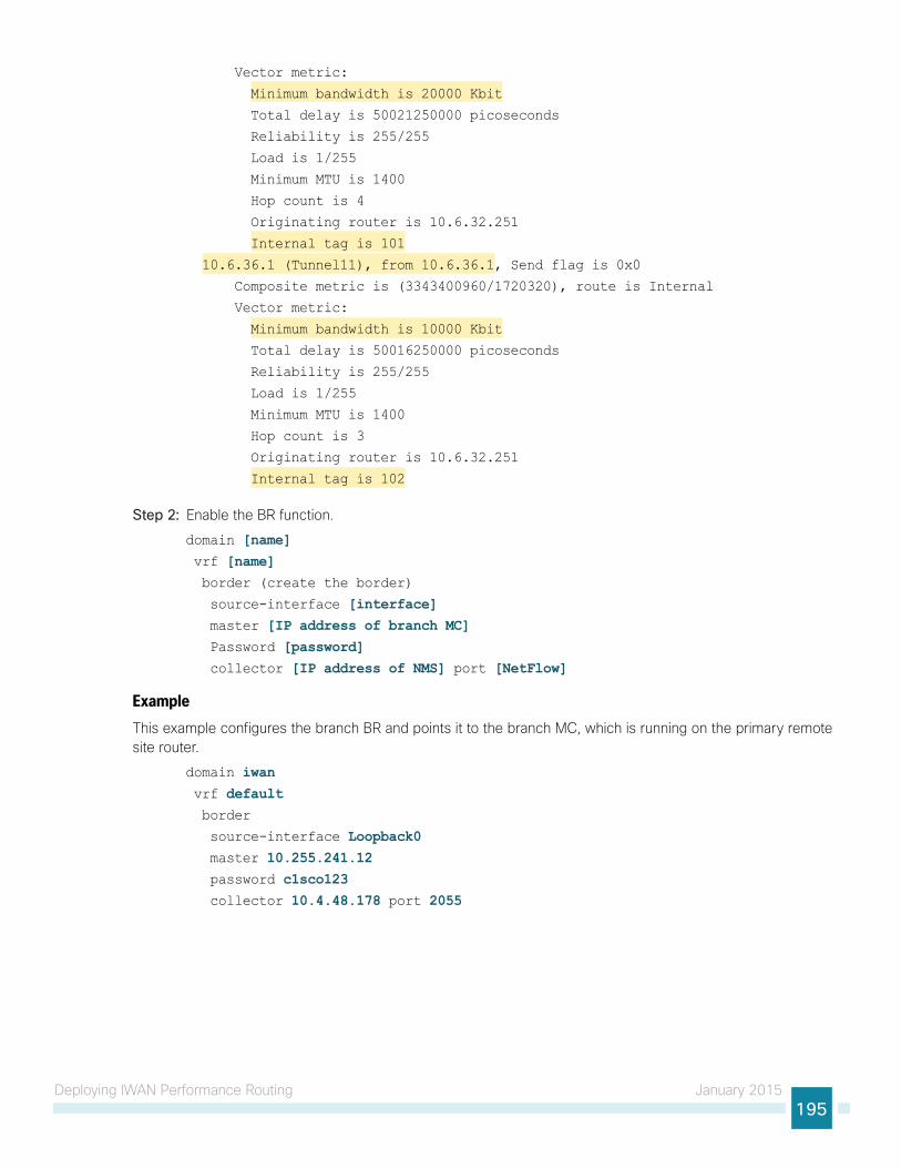
Deploying IWAN Performance Routing January 2015195
Vector metric:
Minimum bandwidth is 20000 Kbit
Total delay is 50021250000 picoseconds
Reliability is 255/255
Load is 1/255
Minimum MTU is 1400
Hop count is 4
Originating router is 10.6.32.251
Internal tag is 101
10.6.36.1 (Tunnel11), from 10.6.36.1, Send flag is 0x0
Composite metric is (3343400960/1720320), route is Internal
Vector metric:
Minimum bandwidth is 10000 Kbit
Total delay is 50016250000 picoseconds
Reliability is 255/255
Load is 1/255
Minimum MTU is 1400
Hop count is 3
Originating router is 10.6.32.251
Internal tag is 102
Step 2: Enable the BR function.
domain [name] vrf [name] border (create the border)
source-interface [interface] master [IP address of branch MC] Password [password] collector [IP address of NMS] port [NetFlow]
ExampleThis example configures the branch BR and points it to the branch MC, which is running on the primary remote site router.
domain iwan vrf default border
source-interface Loopback0 master 10.255.241.12 password c1sco123 collector 10.4.48.178 port 2055

Deploying IWAN Performance Routing January 2015196
Step 3: After approximately thirty seconds, the console displays several EIGRP messages and a line protocol up/down message similar to the ones below. These messages indicate the branch BR has neighbored with the branch MC and automatically generated the tunnel interface from the loopback of the branch BR to the loopback of the branch MC.
Dec 5 16:09:11.202: %DUAL-5-NBRCHANGE: EIGRP-SFv4 59501: Neighbor 10.7.18.2
(Port-channel2.64) is up: new adjacency
Dec 5 16:09:11.202: %DUAL-5-NBRCHANGE: EIGRP-SFv4 59501: Neighbor 10.7.19.2
(Port-channel2.69) is up: new adjacency
Dec 5 16:09:11.202: %DUAL-5-NBRCHANGE: EIGRP-SFv4 59501: Neighbor 10.255.241.12
(Loopback0) is up: new adjacency
Dec 5 16:09:11.690: %DUAL-5-NBRCHANGE: EIGRP-SFv4 59501: Neighbor 10.7.16.9
(Port-channel2.99) is up: new adjacency
Dec 5 16:09:12.174: %LINEPROTO-5-UPDOWN: Line protocol on Interface Tunnel0,
changed state to up
Step 4: Verify that the branch BR is operational by using the show domain [name] border status command.
This example shows the secondary branch BR operational in the IWAN Hybrid model and the external WAN interface is up. There is only one external WAN interface listed because the other tunnel is on the primary remote site router. The primary branch BR is reachable through the automatically generated Tunnel 0 interface at IP address 10.255.241.12.
RS12-2911-2# show domain iwan border statusFri Dec 05 16:10:38.925
--------------------------------------------------------------------
****Border Status****
Instance Status: UP
Present status last updated: 00:01:27 ago
Loopback: Configured Loopback0 UP (10.255.242.12)
Master: 10.255.241.12
Connection Status with Master: UP
MC connection info: CONNECTION SUCCESSFUL
Connected for: 00:01:27
Route-Control: Enabled
Minimum Mask length: 28
Sampling: off
Minimum Requirement: Met
External Wan interfaces:
Name: Tunnel11 Interface Index: 15 SNMP Index: 12 SP:INET Status: UP
Auto Tunnel information:
Name:Tunnel0 if_index: 20
Borders reachable via this tunnel: 10.255.241.12,
Step 5: Repeat Procedure 1 thru Procedure 3 for each remote site in your network.
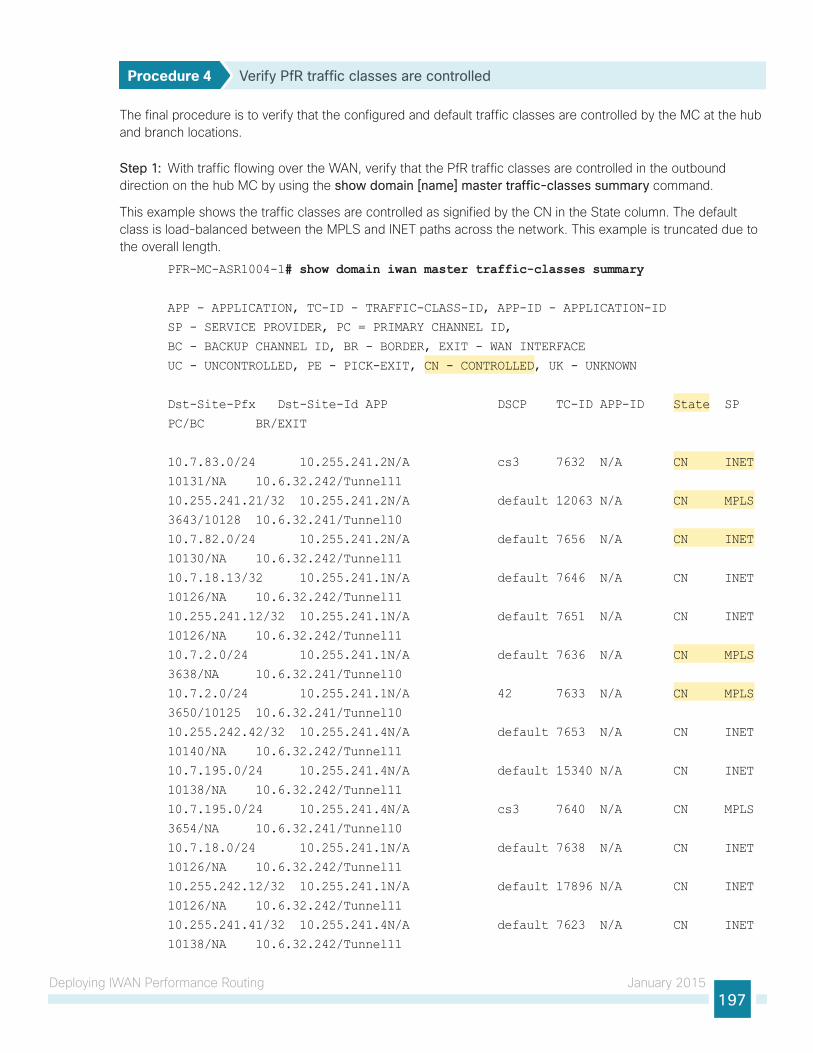
Deploying IWAN Performance Routing January 2015197
Procedure 4 Verify PfR traffic classes are controlled
The final procedure is to verify that the configured and default traffic classes are controlled by the MC at the hub and branch locations.
Step 1: With traffic flowing over the WAN, verify that the PfR traffic classes are controlled in the outbound direction on the hub MC by using the show domain [name] master traffic-classes summary command.
This example shows the traffic classes are controlled as signified by the CN in the State column. The default class is load-balanced between the MPLS and INET paths across the network. This example is truncated due to the overall length.
PFR-MC-ASR1004-1# show domain iwan master traffic-classes summary
APP - APPLICATION, TC-ID - TRAFFIC-CLASS-ID, APP-ID - APPLICATION-ID
SP - SERVICE PROVIDER, PC = PRIMARY CHANNEL ID,
BC - BACKUP CHANNEL ID, BR - BORDER, EXIT - WAN INTERFACE
UC - UNCONTROLLED, PE - PICK-EXIT, CN - CONTROLLED, UK - UNKNOWN
Dst-Site-Pfx Dst-Site-Id APP DSCP TC-ID APP-ID State SP
PC/BC BR/EXIT
10.7.83.0/24 10.255.241.2N/A cs3 7632 N/A CN INET
10131/NA 10.6.32.242/Tunnel11
10.255.241.21/32 10.255.241.2N/A default 12063 N/A CN MPLS
3643/10128 10.6.32.241/Tunnel10
10.7.82.0/24 10.255.241.2N/A default 7656 N/A CN INET
10130/NA 10.6.32.242/Tunnel11
10.7.18.13/32 10.255.241.1N/A default 7646 N/A CN INET
10126/NA 10.6.32.242/Tunnel11
10.255.241.12/32 10.255.241.1N/A default 7651 N/A CN INET
10126/NA 10.6.32.242/Tunnel11
10.7.2.0/24 10.255.241.1N/A default 7636 N/A CN MPLS
3638/NA 10.6.32.241/Tunnel10
10.7.2.0/24 10.255.241.1N/A 42 7633 N/A CN MPLS
3650/10125 10.6.32.241/Tunnel10
10.255.242.42/32 10.255.241.4N/A default 7653 N/A CN INET
10140/NA 10.6.32.242/Tunnel11
10.7.195.0/24 10.255.241.4N/A default 15340 N/A CN INET
10138/NA 10.6.32.242/Tunnel11
10.7.195.0/24 10.255.241.4N/A cs3 7640 N/A CN MPLS
3654/NA 10.6.32.241/Tunnel10
10.7.18.0/24 10.255.241.1N/A default 7638 N/A CN INET
10126/NA 10.6.32.242/Tunnel11
10.255.242.12/32 10.255.241.1N/A default 17896 N/A CN INET
10126/NA 10.6.32.242/Tunnel11
10.255.241.41/32 10.255.241.4N/A default 7623 N/A CN INET
10138/NA 10.6.32.242/Tunnel11

Deploying IWAN Performance Routing January 2015198
Step 2: With traffic flowing over the WAN, verify that the PfR traffic classes are controlled in the outbound direction on one of the branch MC routers by using the show domain [name] master traffic-classes dscp command.
This example shows a video call is taking place from remote site RS11 to the HQ location. The traffic class is controlled, as signified by the Present State row. The INTERACTIVE-VIDEO, with a DSCP of AF41 (34), is in-policy and using the MPLS path. The traffic class has a valid backup channel, which means the INET path is available if the primary path falls out of policy.
RS11-2921# show domain iwan master traffic-classes dscp af41
Dst-Site-Prefix: 10.4.0.0/16 DSCP: af41 [34] Traffic class id:304
TC Learned: 00:00:31 ago
Present State: CONTROLLED
Current Performance Status: in-policy
Current Service Provider: MPLS since 00:00:01 (hold until 88 sec)
Previous Service Provider: Unknown
BW Used: 416 Kbps
Present WAN interface: Tunnel10 in Border 10.255.241.11
Present Channel (primary): 312
Backup Channel: 313
Destination Site ID: 10.6.32.251
Class-Sequence in use: 20
Class Name: INTERACTIVE-VIDEO using policy real-time-video
BW Updated: 00:00:01 ago
Reason for Route Change: Uncontrolled to Controlled Transition
--------------------------------------------------------------------

Deploying IWAN Performance Routing January 2015199
NetFlow monitoring with LiveAction is configured in the “Deploying IWAN Monitoring” process later in this guide. The example below shows the AF41 traffic flow through the MPLS path under normal conditions.
Figure 33 - LiveAction: AF41 traffic flow through the MPLS path on tunnel 10
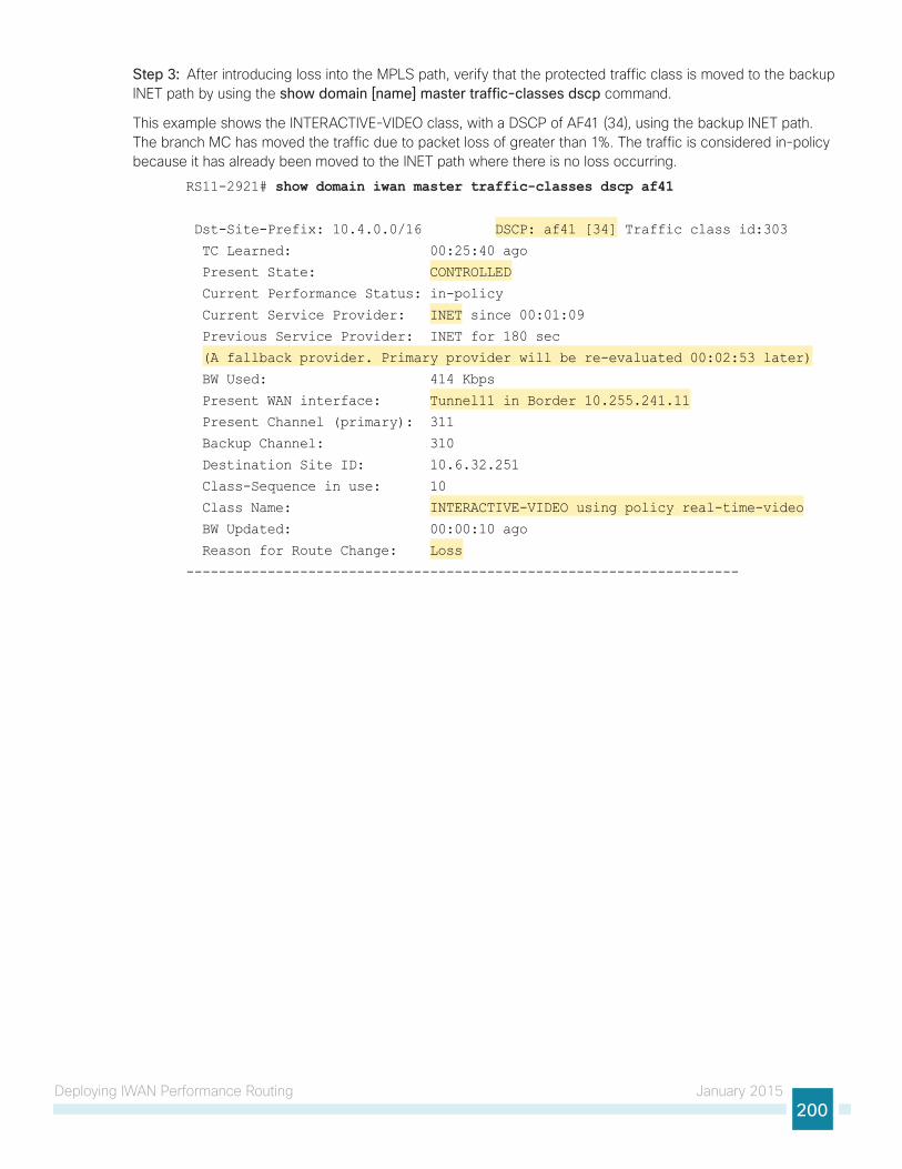
Deploying IWAN Performance Routing January 2015200
Step 3: After introducing loss into the MPLS path, verify that the protected traffic class is moved to the backup INET path by using the show domain [name] master traffic-classes dscp command.
This example shows the INTERACTIVE-VIDEO class, with a DSCP of AF41 (34), using the backup INET path. The branch MC has moved the traffic due to packet loss of greater than 1%. The traffic is considered in-policy because it has already been moved to the INET path where there is no loss occurring.
RS11-2921# show domain iwan master traffic-classes dscp af41
Dst-Site-Prefix: 10.4.0.0/16 DSCP: af41 [34] Traffic class id:303
TC Learned: 00:25:40 ago
Present State: CONTROLLED
Current Performance Status: in-policy
Current Service Provider: INET since 00:01:09
Previous Service Provider: INET for 180 sec
(A fallback provider. Primary provider will be re-evaluated 00:02:53 later)
BW Used: 414 Kbps
Present WAN interface: Tunnel11 in Border 10.255.241.11
Present Channel (primary): 311
Backup Channel: 310
Destination Site ID: 10.6.32.251
Class-Sequence in use: 10
Class Name: INTERACTIVE-VIDEO using policy real-time-video
BW Updated: 00:00:10 ago
Reason for Route Change: Loss
--------------------------------------------------------------------

Deploying IWAN Performance Routing January 2015201
NetFlow monitoring with LiveAction is configured in the “Deploying IWAN Monitoring” process later in this guide. The example below shows the AF41 traffic flow through the INET path after loss has been introduced on the MPLS path.
Figure 34 - LiveAction: AF41 traffic flow through the INET path on tunnel 11 after loss
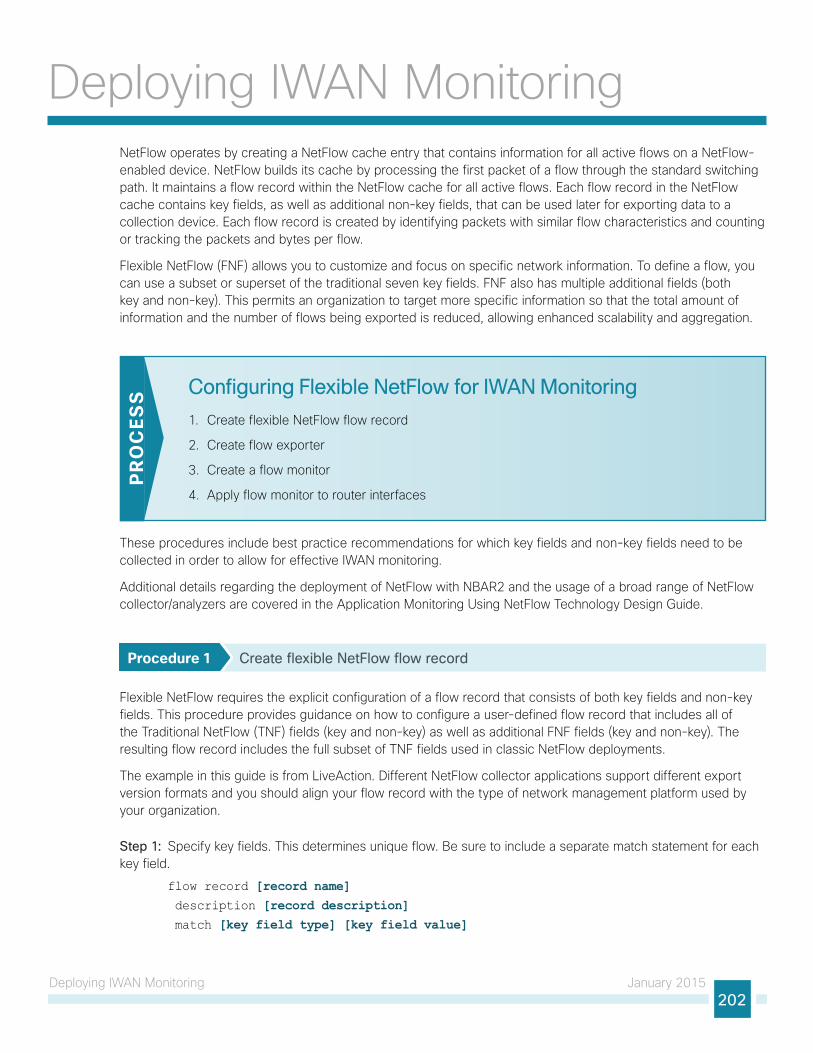
Deploying IWAN Monitoring January 2015202
Deploying IWAN MonitoringNetFlow operates by creating a NetFlow cache entry that contains information for all active flows on a NetFlow-enabled device. NetFlow builds its cache by processing the first packet of a flow through the standard switching path. It maintains a flow record within the NetFlow cache for all active flows. Each flow record in the NetFlow cache contains key fields, as well as additional non-key fields, that can be used later for exporting data to a collection device. Each flow record is created by identifying packets with similar flow characteristics and counting or tracking the packets and bytes per flow.
Flexible NetFlow (FNF) allows you to customize and focus on specific network information. To define a flow, you can use a subset or superset of the traditional seven key fields. FNF also has multiple additional fields (both key and non-key). This permits an organization to target more specific information so that the total amount of information and the number of flows being exported is reduced, allowing enhanced scalability and aggregation.
Configuring Flexible NetFlow for IWAN Monitoring
1. Create flexible NetFlow flow record
2. Create flow exporter
3. Create a flow monitor
4. Apply flow monitor to router interfaces
PR
OC
ESS
These procedures include best practice recommendations for which key fields and non-key fields need to be collected in order to allow for effective IWAN monitoring.
Additional details regarding the deployment of NetFlow with NBAR2 and the usage of a broad range of NetFlow collector/analyzers are covered in the Application Monitoring Using NetFlow Technology Design Guide.
Procedure 1 Create flexible NetFlow flow record
Flexible NetFlow requires the explicit configuration of a flow record that consists of both key fields and non-key fields. This procedure provides guidance on how to configure a user-defined flow record that includes all of the Traditional NetFlow (TNF) fields (key and non-key) as well as additional FNF fields (key and non-key). The resulting flow record includes the full subset of TNF fields used in classic NetFlow deployments.
The example in this guide is from LiveAction. Different NetFlow collector applications support different export version formats and you should align your flow record with the type of network management platform used by your organization.
Step 1: Specify key fields. This determines unique flow. Be sure to include a separate match statement for each key field.
flow record [record name] description [record description] match [key field type] [key field value]

Deploying IWAN Monitoring January 2015203
Table 66 - Recommended FNF key fields for IWAN
Key field type Key field value
flow direction
interface input
ipv4 tos
protocol
source address
destination address
transport source port
destination port
Step 2: Specify non-key fields to be collected for each unique flow. Be sure to include a separate collect statement for each non-key field.
flow record [record name] collect [non-key field type] [non-key field value]
Table 67 - Recommended FNF non-key fields for IWAN
Non-key field type Non-key field value
application name
flow sampler
routing source as
destination as
next-hop address ipv4
ipv4 source prefix
source mask
destination mask
dscp
id
transport tcp flags
interface output
counter bytes
packets
timestamp sys-uptime first
sys-uptime last
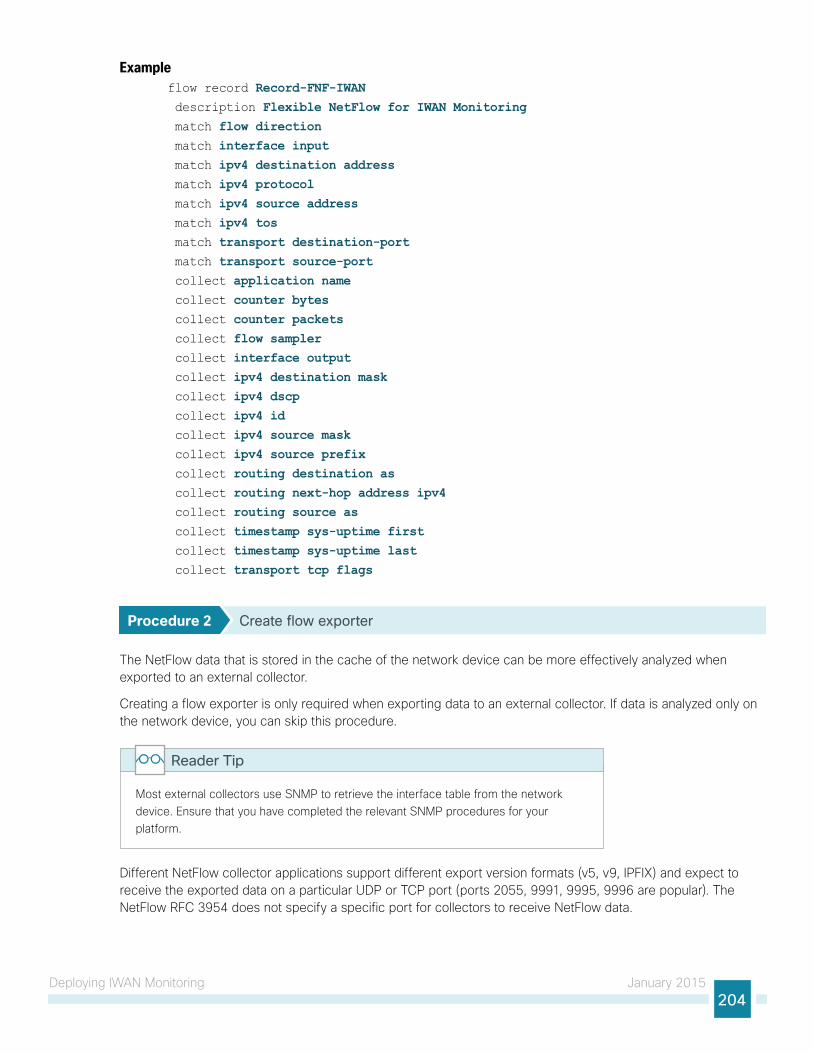
Deploying IWAN Monitoring January 2015204
Exampleflow record Record-FNF-IWAN description Flexible NetFlow for IWAN Monitoring match flow direction match interface input match ipv4 destination address match ipv4 protocol match ipv4 source address match ipv4 tos match transport destination-port match transport source-port collect application name collect counter bytes collect counter packets collect flow sampler collect interface output collect ipv4 destination mask collect ipv4 dscp collect ipv4 id collect ipv4 source mask collect ipv4 source prefix collect routing destination as collect routing next-hop address ipv4 collect routing source as collect timestamp sys-uptime first collect timestamp sys-uptime last collect transport tcp flags
Procedure 2 Create flow exporter
The NetFlow data that is stored in the cache of the network device can be more effectively analyzed when exported to an external collector.
Creating a flow exporter is only required when exporting data to an external collector. If data is analyzed only on the network device, you can skip this procedure.
Most external collectors use SNMP to retrieve the interface table from the network device. Ensure that you have completed the relevant SNMP procedures for your platform.
Reader Tip
Different NetFlow collector applications support different export version formats (v5, v9, IPFIX) and expect to receive the exported data on a particular UDP or TCP port (ports 2055, 9991, 9995, 9996 are popular). The NetFlow RFC 3954 does not specify a specific port for collectors to receive NetFlow data.

Deploying IWAN Monitoring January 2015205
In this deployment, the collector applications used for testing use the parameters designated in the following table.
Table 68 - NetFlow collector parameters
Vendor Application Version Export capability Netflow destination port
LiveAction LiveAction 4.1.2 Flexible NetFlow v9 UDP 2055
Step 1: Configure a basic flow exporter by using Netflow v9.
flow exporter [exporter name] description [exporter description] destination [NetFlow collector IP address] source Loopback0
transport [UDP or TCP] [port number] export-protocol netflow
Step 2: For FNF records, export the interface table for FNF. The option interface-table command enables the periodic sending of an options table. This provides interface names through the NetFlow export.
flow exporter [exporter name] option interface-table
template data timeout 600
Step 3: If you are using an NBAR flow record, export the NBAR application table. The option application-table command enables the periodic sending of an options table that allows the collector to map the NBAR application IDs provided in the flow records to application names.
flow exporter [exporter name] option application-table
Step 4: If you are using an NBAR flow record, export the NBAR application attributes. The option application-attributes command causes the periodic sending of NBAR application attributes to the collector.
flow exporter [exporter name] option application-attributes
Step 5: If you are using the Cisco ISR-G2 series routers, enable output-features. Otherwise, NetFlow traffic that originates from a WAN remote-site router will not be encrypted or tagged using QoS.
flow exporter [exporter name] output-features
Example: FNF with LiveActionflow exporter Export-FNF-LiveAction description FNFv9 with LiveAction destination 10.4.48.178 source Loopback0
output-features ! this command is not required on IOS-XE routers
transport udp 2055 template data timeout 600 option interface-table
option application-table
option application-attributes
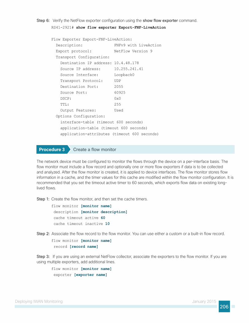
Deploying IWAN Monitoring January 2015206
Step 6: Verify the NetFlow exporter configuration using the show flow exporter command.
RS41-2921# show flow exporter Export-FNF-LiveAction
Flow Exporter Export-FNF-LiveAction:
Description: FNFv9 with LiveAction
Export protocol: NetFlow Version 9
Transport Configuration:
Destination IP address: 10.4.48.178
Source IP address: 10.255.241.41
Source Interface: Loopback0
Transport Protocol: UDP
Destination Port: 2055
Source Port: 60925
DSCP: 0x0
TTL: 255
Output Features: Used
Options Configuration:
interface-table (timeout 600 seconds)
application-table (timeout 600 seconds)
application-attributes (timeout 600 seconds)
Procedure 3 Create a flow monitor
The network device must be configured to monitor the flows through the device on a per-interface basis. The flow monitor must include a flow record and optionally one or more flow exporters if data is to be collected and analyzed. After the flow monitor is created, it is applied to device interfaces. The flow monitor stores flow information in a cache, and the timer values for this cache are modified within the flow monitor configuration. It is recommended that you set the timeout active timer to 60 seconds, which exports flow data on existing long-lived flows.
Step 1: Create the flow monitor, and then set the cache timers.
flow monitor [monitor name] description [monitor description] cache timeout active 60 cache timeout inactive 10
Step 2: Associate the flow record to the flow monitor. You can use either a custom or a built-in flow record.
flow monitor [monitor name] record [record name]
Step 3: If you are using an external NetFlow collector, associate the exporters to the flow monitor. If you are using multiple exporters, add additional lines.
flow monitor [monitor name] exporter [exporter name]

Deploying IWAN Monitoring January 2015207
Example: FNF with LiveActionflow monitor Monitor-FNF-IWAN description IWAN Traffic Analysis record Record-FNF-IWAN exporter Export-FNF-LiveAction cache timeout active 60 cache timeout inactive 10
Step 4: Verify the flow monitor configuration by using the show flow monitor command.
RS41-2921#show flow monitor Flow Monitor Monitor-FNF-IWAN:
Description: IWAN Traffic Analysis
Flow Record: Record-FNF-IWAN
Flow Exporter: Export-FNF-LiveAction (inactive)
Cache:
Type: normal
Status: not allocated
Size: 4096 entries / 0 bytes
Inactive Timeout: 10 secs
Active Timeout: 60 secs
Update Timeout: 1800 secs
Synchronized Timeout: 600 secs
Status: allocated
Size: 4096 entries / 376856 bytes
Inactive Timeout: 15 secs
Active Timeout: 60 secs
Update Timeout: 1800 secs
Procedure 4 Apply flow monitor to router interfaces
A best practice for NetFlow in an IWAN deployment is to monitor all inbound and outbound traffic on the DMVPN tunnel interfaces.
Step 1: Apply the flow monitor to the tunnel interface(s).
interface [name] ip flow monitor [monitor name] input ip flow monitor [monitor name] output
Example: Single-router dual-link remote siteinterface Tunnel10 ip flow monitor Monitor-FNF-IWAN input ip flow monitor Monitor-FNF-IWAN output
interface Tunnel11 ip flow monitor Monitor-FNF-IWAN input ip flow monitor Monitor-FNF-IWAN output

Deploying IWAN Monitoring January 2015208
Step 2: Verify the proper interfaces are configured for NetFlow monitoring using the show flow interface command.
RS41-2921# show flow interface Interface Tunnel10
FNF: monitor: Monitor-FNF-IWAN
direction: Input
traffic(ip): on
FNF: monitor: Monitor-FNF-IWAN
direction: Output
traffic(ip): on
Interface Tunnel11
FNF: monitor: Monitor-FNF-IWAN
direction: Input
traffic(ip): on
FNF: monitor: Monitor-FNF-IWAN
direction: Output
traffic(ip): on
Step 3: At dual-router sites with a distribution layer, also apply the flow monitor to the interfaces that connect to the distribution layer switch. This ensures that you capture all possible traffic flows.
Example: First router of a dual-router dual-link remote siteinterface Port-channel1.50 ip flow monitor Monitor-FNF-IWAN input ip flow monitor Monitor-FNF-IWAN output
Example: Second router of a dual-router dual-link remote siteinterface Port-channel2.54 ip flow monitor Monitor-FNF-IWAN input ip flow monitor Monitor-FNF-IWAN output
Step 4: Verify the dscp used in the network by displaying the NetFlow cache on the WAN aggregation routers. Use the show flow monitor command.
This example is truncated due to the width and overall length.
show flow monitor Monitor-FNF-IWAN cache format table Cache type: Normal (Platform cache)
Cache size: 200000
Current entries: 217
High Watermark: 1190
Flows added: 9904555
Flows aged: 9904338
- Active timeout ( 60 secs) 1028876
- Inactive timeout ( 10 secs) 8875462

Deploying IWAN Monitoring January 2015209
IPV4 SRC ADDR IPV4 DST ADDR TRNS SRC PORT TRNS DST PORT INTF INPUT
FLOW DIRN IP TOS IP PROT ip src as ip dst as ipv4 next hop addr ipv4
id ipv4 src prefix ipv4 src mask ipv4 dst mask tcp flags intf output
flow sampler id bytes pkts time first time last ip dscp app
name
=============== ============= ============== ============== =============
10.6.32.251 10.255.241.31 18000 19000
Null Output 0xA8 17 0 0
10.6.34.31 0 0.0.0.0 /0 /23 0x00
Tu10 0 16632 231 10:29:20.873
10:29:32.053 0x2A layer7 rtp
10.7.83.20 10.4.48.111 50166 2000
Tu10 Output 0x60 6 0 0
10.6.32.1 7960 10.7.80.0 /21 /15 0x18
Po1 0 92 2 10:29:25.261
10:29:25.277 0x18 layer7 skinny
10.4.48.178 10.255.241.32 0 771
Po1 Input 0x00 1 0 0
10.6.32.242 9581 10.4.0.0 /15 /32 0x00
Tu0 0 1972 11 10:29:14.505
10:29:32.031 0x00 prot icmp
1

Appendix A: Product List January 2015210
Appendix A: Product ListWAN Aggregation
Place In Network Product Description Part Number SW Version Feature Set
WAN-aggregation Router
Aggregation Services 1002X Router ASR1002X-5G-VPNK9 IOS-XE 15.5(1)S Advanced Enterprise
Cisco ISR 4451-X Security Bundle w/SEC license PAK
ISR4451-X-SEC/K9 IOS-XE 15.5(1)S securityk9
WAN Remote SitePlace In Network Product Desccription Part Number SW Version Feature Set
Modular WAN Remote-site Router
Cisco ISR 4451 w/ 4GE,3NIM,2SM,8G FLASH, 4G DRAM, IP Base, SEC, AX license with: DATA, AVC, ISR-WAAS with 2500 connection RTU
ISR4451-X-AX/K9 IOS-XE 15.5(1)S securityk9, appxk9
Cisco ISR 3945 w/ SPE150, 3GE, 4EHWIC, 4DSP, 4SM, 256MBCF, 1GBDRAM, IP Base, SEC, AX licenses with; DATA, AVC, and WAAS/vWAAS with 2500 connection RTU
C3945-AX/K9 15.4(3)M1 securityk9, datak9, uck9
Cisco ISR 3925 w/ SPE100 (3GE, 4EHWIC, 4DSP, 2SM, 256MBCF, 1GBDRAM, IP Base, SEC, AXlicenses with; DATA, AVC, WAAS/vWAAS with 2500 connection RTU
C3925-AX/K9 15.4(3)M1 securityk9, datak9, uck9
Unified Communications Paper PAK for Cisco 3900 Series
SL-39-UC-K9
Cisco ISR 2951 w/ 3 GE, 4 EHWIC, 3 DSP, 2 SM, 256MB CF, 1GB DRAM, IP Base, SEC, AX license with; DATA, AVC, and WAAS/vWAAS with 1300 connection RTU
C2951-AX/K9 15.4(3)M1 securityk9, datak9, uck9
Cisco ISR 2921 w/ 3 GE, 4 EHWIC, 3 DSP, 1 SM, 256MB CF, 1GB DRAM, IP Base, SEC, AX license with; DATA, AVC, and WAAS/vWAAS with 1300 connection RTU
C2921-AX/K9 15.4(3)M1 securityk9, datak9, uck9
Cisco ISR 2911 w/ 3 GE,4 EHWIC, 2 DSP, 1 SM, 256MB CF, 1GB DRAM, IP Base, SEC, AX license with; DATA, AVC and WAAS/vWAAS with 1300 connection RTU
C2911-AX/K9 15.4(3)M1 securityk9, datak9, uck9
Unified Communications Paper PAK for Cisco 2900 Series
SL-29-UC-K9
Cisco ISR 1941 Router w/ 2 GE, 2 EHWIC slots, 256MB CF, 2.5GB DRAM, IP Base, DATA, SEC, AX license with; AVC and WAAS-Express
C1941-AX/K9 15.4(3)M1 securityk9, datak9

Appendix A: Product List January 2015211
Internet EdgePlace In Network Product Description Part Number SW Version Feature Set
Firewall Cisco ASA 5545-X IPS Edition - security appliance ASA5545-IPS-K9 ASA 9.1(5), IPS 7.1(8p2) E4
Cisco ASA 5525-X IPS Edition - security appliance ASA5525-IPS-K9 ASA 9.1(5), IPS 7.1(8p2) E4
Cisco ASA 5515-X IPS Edition - security appliance ASA5515-IPS-K9 ASA 9.1(5), IPS 7.1(8p2) E4
Cisco ASA 5512-X IPS Edition - security appliance ASA5512-IPS-K9 ASA 9.1(5), IPS 7.1(8p2) E4
Cisco ASA 5512-X Security Plus license ASA5512-SEC-PL
Firewall Management ASDM 7.1(6)
Internet Edge LANPlace In Network Product Description Part Number SW Version Feature Set
DMZ Switch Cisco Catalyst 2960-X Series 24 10/100/1000 PoE and 2 SFP+ Uplink
WS-C2960X-24PS 15.0(2)EX5 LAN Base
Cisco Catalyst 2960-X FlexStack-Plus Hot-Swappable Stacking Module
C2960X-STACK
LAN Access LayerPlace In Network Product Description Part Number SW Version Feature Set
Modular Access Layer Switch
Cisco Catalyst 4500E Series 4507R+E 7-slot Chassis with 48Gbps per slot
WS-C4507R+E 3.3.1XO(15.1.1XO1) IP Base
Cisco Catalyst 4500E Supervisor Engine 8-E, Unified Access, 928Gbps
WS-X45-SUP8-E 3.3.1XO(15.1.1XO1) IP Base
Cisco Catalyst 4500E 12-port 10GbE SFP+ Fiber Module
WS-X4712-SFP+E
Cisco Catalyst 4500E 48-Port 802.3at PoE+ 10/100/1000 (RJ-45)
WS-X4748-RJ45V+E
Cisco Catalyst 4500E Series 4507R+E 7-slot Chassis with 48Gbps per slot
WS-C4507R+E 3.5.3E(15.2.1E3) IP Base
Cisco Catalyst 4500E Supervisor Engine 7L-E, 520Gbps
WS-X45-SUP7L-E 3.5.3E(15.2.1E3) IP Base
Cisco Catalyst 4500E 48 Ethernet 10/100/1000 (RJ45) PoE+,UPoE ports
WS-X4748-UPOE+E
Cisco Catalyst 4500E 48 Ethernet 10/100/1000 (RJ45) PoE+ ports
WS-X4648-RJ45V+E

Appendix A: Product List January 2015212
Place In Network Product Description Part Number SW Version Feature Set
Stackable Access Layer Switch
Cisco Catalyst 3850 Series Stackable 48 Ethernet 10/100/1000 PoE+ ports
WS-C3850-48F 3.3.3SE(15.0.1EZ3) IP Base
Cisco Catalyst 3850 Series Stackable 24 Ethernet 10/100/1000 PoE+ Ports
WS-C3850-24P 3.3.3SE(15.0.1EZ3) IP Base
Cisco Catalyst 3850 Series 2 x 10GE Network Module
C3850-NM-2-10G
Cisco Catalyst 3850 Series 4 x 1GE Network Module C3850-NM-4-1G
Cisco Catalyst 3650 Series 24 Ethernet 10/100/1000 PoE+ and 2x10GE or 4x1GE Uplink
WS-C3650-24PD 3.3.3SE(15.0.1EZ3) IP Base
Cisco Catalyst 3650 Series 24 Ethernet 10/100/1000 PoE+ and 4x1GE Uplink
WS-C3650-24PS 3.3.3SE(15.0.1EZ3) IP Base
Cisco Catalyst 3650 Series Stack Module C3650-STACK
Cisco Catalyst 3750-X Series Stackable 48 Ethernet 10/100/1000 PoE+ ports
WS-C3750X-48PF-S 15.2(1)E3 IP Base
Cisco Catalyst 3750-X Series Stackable 24 Ethernet 10/100/1000 PoE+ ports
WS-C3750X-24P-S 15.2(1)E3 IP Base
Cisco Catalyst 3750-X Series Two 10GbE SFP+ and Two GbE SFP ports network module
C3KX-NM-10G
Cisco Catalyst 3750-X Series Four GbE SFP ports network module
C3KX-NM-1G
Cisco Catalyst 2960-X Series 24 10/100/1000 Ethernet and 2 SFP+ Uplink
WS-C2960X-24PD 15.0(2)EX5 LAN Base
Standalone Access Layer Switch
Cisco Catalyst 3650 Series 24 Ethernet 10/100/1000 PoE+ and 4x1GE Uplink
WS-C3650-24PS 3.3.3SE(15.01EZ3) IP Base

Appendix B: Technical Feature Supplement January 2015213
Appendix B: Technical Feature Supplement
Front Door VRF for DMVPNBuilding an IPsec tunnel requires reachability between the crypto routers. When you use the Internet, routers use a default route to contact their peers.
Figure 35 - IPsec tunnel
20
34
Internet
Inside
Outside
Internet Edge
Default
DefaultVPN-DMZ
Default
Default
DMVPN Hub Router
WAN Distribution
DMVPN Spoke Router
Default Route
If you need to extend the internal network and the same default routing options that are available to internal users, you must advertise a default route to the VPN hub router. For details, see section A in the following figure.

Appendix B: Technical Feature Supplement January 2015214
Figure 36 - IPsec tunnel before/after default route injection
A
Internet
Inside
Outside
Internet Edge
Default
DefaultVPN-DMZ
Default
Default
DMVPNHub Router
WANDistribution
DMVPNSpokeRouter
EIGRP
Default
B
Internet
Inside
Outside
Internet Edge
Default
DefaultVPN-DMZ
Default
Default
DMVPNHub Router
WANDistribution
DMVPNSpokeRouter
EIGRP
20
35
Default
The advertisement of a default route to the hub router (with an existing default route) is problematic. This route requires a better administrative distance to become the active default, which then overrides the default route that is supporting the peer-peer IPsec tunnel connection. This routing advertisement breaks the tunnel as shown in section B in the previous figure.
Through the introduction of an external VRF INET-PUBLIC (shown in red), the hub router can support multiple default routes. The internal network remains in the global VRF. This is shown in section A of the following figure.
Most additional features on the hub router do not require VRF-awareness.
Tech Tip

Appendix B: Technical Feature Supplement January 2015215
Figure 37 - IPsec tunnel with FVRF aggregation
20
36
Internet
Inside
Outside
InternetEdgeBlock
Default
Default
DefaultVPN-DMZ
Default
A
WANDistribution
vrf global vrf INET-PUBLIC
EIGRP
(200)
Default RouteDefault Route (vrf INET-PUBLIC)
DMVPNSpokeRouter
DefaultInternet
Inside
Outside
InternetEdgeBlock
Default
DefaultVPN-DMZ
Default
B
WANDistribution
vrf global vrf INET-PUBLIC
DMVPNSpokeRouter
Default
This configuration is referred to as FVRF, because the Internet is contained in a VRF. FVRF is sometimes referred to as Front Side VRF. The alternative to this design is Inside VRF (IVRF), where the internal network is in a VRF on the VPN hub and the Internet remains in the global VRF. This method is not documented in this guide.
It is now possible to reestablish the IPSec tunnel to the remote peer router. Because the remote-site policy requires central Internet access for end users, a default route is advertised through the tunnel. This advertisement causes a similar default routing issue on the remote router; the tunnel default overrides the Internet-pointing default and the tunnel connection breaks as shown in section B of the previous figure.
This configuration requires using FVRF on the remote-site router as well. The primary benefits of using this solution are:
• Simplified default routing and static default routes in the INET-PUBLIC VRFs.
• Ability to support default routing for end-users traffic through VPN tunnels.
• Ability to use dynamic default routing for sites with multiple WAN transports.
• Ability to build spoke-to-spoke tunnels with DMVPN with end-user traffic routed by default through VPN tunnels.

Appendix B: Technical Feature Supplement January 2015216
The final design that uses FVRF at both the WAN-aggregation site and a WAN remote-site is shown in the following figure.
Figure 38 - FVRF: Final configuration
20
37
Inside
Outside
InternetEdge
Default
DefaultDefault
VPN-DMZ
Default
Default
Default Route
DMVPN Hub Router
WAN Distribution
vrf global vrf INET-PUBLIC
vrf global vrf INET-PUBLIC
Default Route (vrf INET-PUBLIC)
DMVPN Spoke Router
EIGRP
(200)
Internet

Appendix C: Device Configuration Files January 2015217
Appendix C: Device Configuration Files
To view the configuration files from the CVD lab devices that were used to test this guide, go to the following URL:
http://cvddocs.com/fw/201i-15a

Americas HeadquartersCisco Systems, Inc.San Jose, CA
Asia Pacific HeadquartersCisco Systems (USA) Pte. Ltd.Singapore
Europe HeadquartersCisco Systems International BV Amsterdam,The Netherlands
Cisco has more than 200 offices worldwide. Addresses, phone numbers, and fax numbers are listed on the Cisco Website at www.cisco.com/go/offices.
ALL DESIGNS, SPECIFICATIONS, STATEMENTS, INFORMATION, AND RECOMMENDATIONS (COLLECTIVELY, “DESIGNS”) IN THIS MANUAL ARE PRESENTED “AS IS,” WITH ALL FAULTS. CISCO AND ITS SUPPLIERS DISCLAIM ALL WARRANTIES, INCLUDING, WITHOUT LIMITATION, THE WARRANTY OF MERCHANTABILITY, FITNESS FOR A PARTICULAR PURPOSE AND NONINFRINGEMENT OR ARISING FROM A COURSE OF DEALING, USAGE, OR TRADE PRACTICE. IN NO EVENT SHALL CISCO OR ITS SUPPLIERS BE LIABLE FOR ANY INDIRECT, SPECIAL, CONSEQUENTIAL, OR INCIDENTAL DAMAGES, INCLUDING, WITHOUT LIMITATION, LOST PROFITS OR LOSS OR DAMAGE TO DATA ARISING OUT OF THE USE OR INABILITY TO USE THE DESIGNS, EVEN IF CISCO OR ITS SUPPLIERS HAVE BEEN ADVISED OF THE POSSIBILITY OF SUCH DAMAGES. THE DESIGNS ARE SUBJECT TO CHANGE WITHOUT NOTICE. USERS ARE SOLELY RESPONSIBLE FOR THEIR APPLICATION OF THE DESIGNS. THE DESIGNS DO NOT CONSTITUTE THE TECHNICAL OR OTHER PROFESSIONAL ADVICE OF CISCO, ITS SUPPLIERS OR PARTNERS. USERS SHOULD CONSULT THEIR OWN TECHNICAL ADVISORS BEFORE IMPLEMENTING THE DESIGNS. RESULTS MAY VARY DEPENDING ON FACTORS NOT TESTED BY CISCO.
Any Internet Protocol (IP) addresses used in this document are not intended to be actual addresses. Any examples, command display output, and figures included in the document are shown for illustrative purposes only. Any use of actual IP addresses in illustrative content is unintentional and coincidental.
© 2015 Cisco Systems, Inc. All rights reserved.
Cisco and the Cisco logo are trademarks or registered trademarks of Cisco and/or its affiliates in the U.S. and other countries. To view a list of Cisco trademarks, go to this URL: www.cisco.com/go/trademarks. Third-party trademarks mentioned are the property of their respective owners. The use of the word partner does not imply a partnership relationship between Cisco and any other company. (1110R)
Please use the feedback form to send comments and suggestions about this guide.
Feedback
B-0000200i-3 08/15