NJDOT - Division 4 NJDOT Design Manual for Bridge Structures
Upload
truongthuanCategory
view
227download
4
Intelligent Transportation Systems Manual
“Draft”
INTELLIGENT
TRANSPORTATION SYSTEMS
(ITS) MANUAL
INSPECTION/ACCEPTANCE
CHECKLISTS
Prepared by
Center for Advanced Infrastructure & Transportation (CAIT)
Rutgers University
June 2007
Intelligent Transportation Systems Manual
Center for Advanced Infrastructure & Transportation 2 Rutgers University
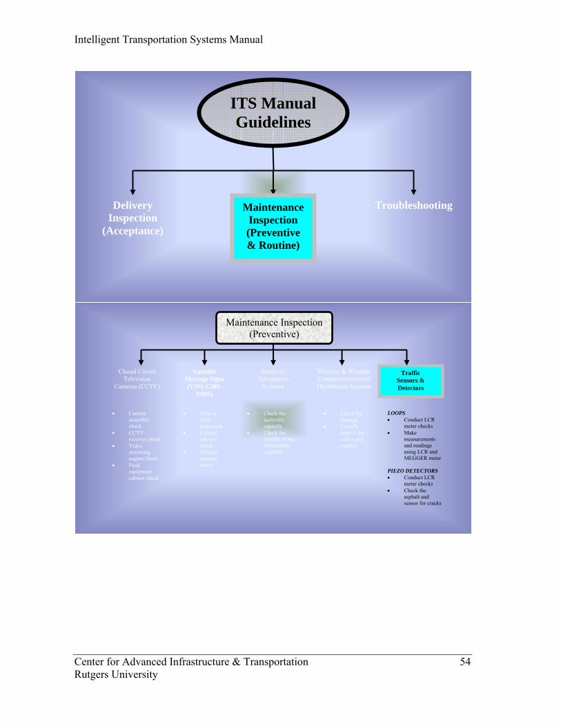
ITS Manual Guidelines
Delivery Inspection
(Acceptance)
Troubleshooting Maintenance Inspection
(Preventive & Routine)
Intelligent Transportation Systems Manual
Center for Advanced Infrastructure & Transportation 3 Rutgers University
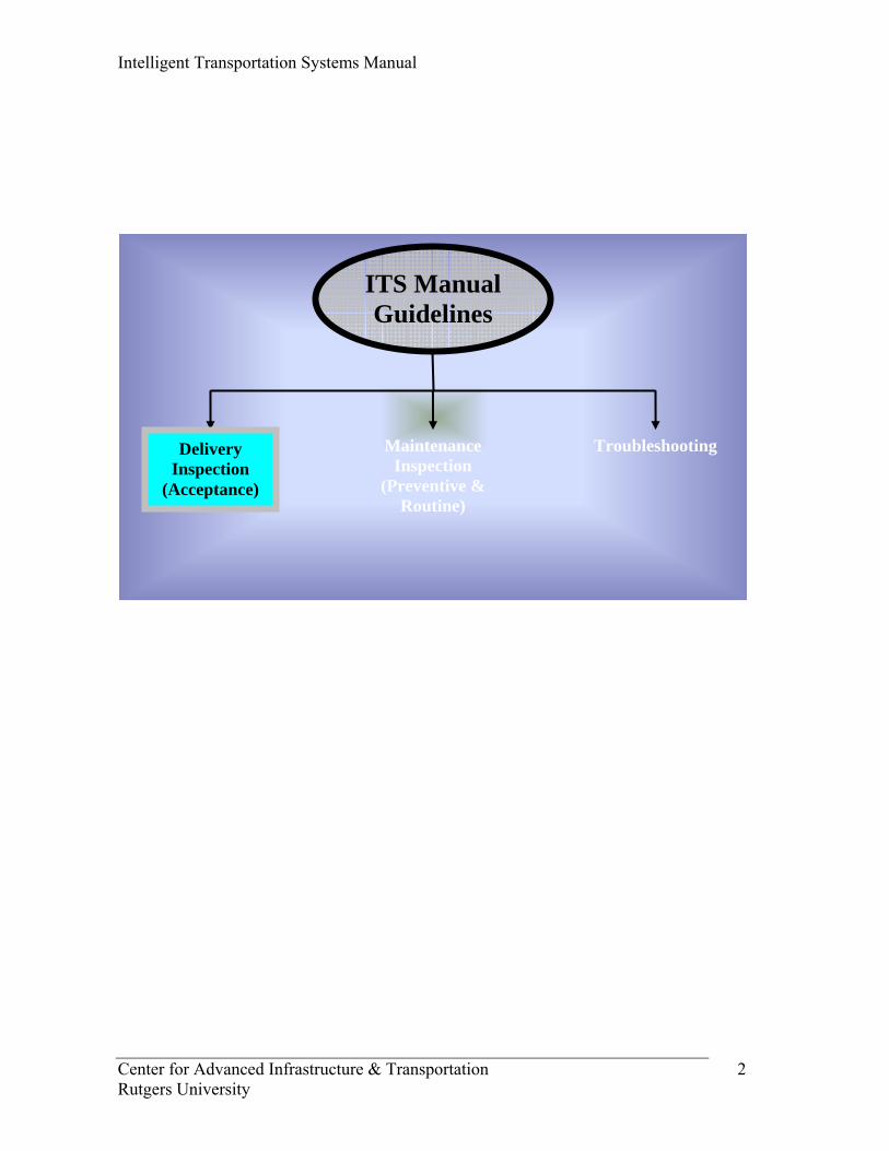
Pre-Construction Inspection Checklist
• Make sure that a constructability review for the design has been performed
regarding these conditions on the site as per contract:
o Ease of accessibility,
o Leveling/level differences/slope,
o Serviceability,
o Power requirements,
o Swelling/flood,
o Access to wiring/fiber-optic lines,
o Security requirements,
o Safety requirements/human factors,
o Right of way,
o Utility mark-out,
o Blind spots (PELCO),
o Attachment of the lowering device.
Pass Fail N/A
Intelligent Transportation Systems Manual
Center for Advanced Infrastructure & Transportation 4 Rutgers University
Conduit Inspection Checklist
• All conduits should be of types approved for electrical use and should have
the proper identification mark and customer identification numbers (NJDOT
approved conduits). Installation should be made in conformance with
minimum requirements of state Electrical Board (EE Number), National
Electrical Code (NEC), and NJDOT standard specifications.
• Check that conduit is the proper size and type as detailed in the plans and
specifications. All materials should be NJDOT approved materials.
• Verify that all subsurface utilities have been located (i.e. marked out) before
excavation begins. NJDOT standard specifications require 1-800 ONE
notification and separate notification to appropriate local NJDOT electrical
and traffic operations maintenance units.
• Check excavation trench width and depth for compliance with plans and
specifications.
• Check that conduit is placed at proper depth and slope. Conduit should drain
into a junction box. Make sure that junction box is also drained.
• Check for proper spacer installation (multiple PVC conduit cross section
only) and support “chairs”.
• Boring or jacking operations should not interfere with traffic operation and
should not damage or weaken roadway structures or pavements. Tolerances
should not exceed the plan or specifications. Any open cuts in the roadway
pavement should be approved by the project engineer (NJDOT). Any
misguided pipe should be removed or abandoned, if can not be removed.
Pass Fail N/A

Intelligent Transportation Systems Manual
Center for Advanced Infrastructure & Transportation 5 Rutgers University
• As a general rule, the radius of the curve of the inner edge of any field bend
shall not be less than the NJDOT and NEC (National Electrical Code)
requirements. Number of bends in a single run of conduit shall not exceed
NJDOT specifications and manufacturer’s specifications.
• PVC conduits should be terminated flush with the top of concrete and the
end of the conduits should be terminated according to NJDOT specifications
and electrical construction details. End bell should be flush with the top of
concrete.
• Metallic conduit should enter the junction boxes at right angles and extend
1.5 in. to 3 in. into the box. It should be terminated with proper (approved)
bushing.
• Nonmetallic conduit should be terminated flush with the inside wall, and
approved end bell shall be used.
• Rigid metal conduit should be cut square, threaded, and reamed on each end
with good workmanship and joined using a threaded coupling or EB allowed
bushing (with appropriate EE number). All threadless connectors should be
approved and waterproofed.
• Galvanized spray should be used on all threaded sections and on any
damaged galvanizing. Replace any pipe with damaged galvanizing.
• PVC conduit ends should also be square and free of burrs and sharp edges.
Joints should be made using a solvent-weld method (glue) in accordance
with the conduit manufacturer’s recommendations. Nonmetallic conduits
should be cleaned before applying the solvent-weld method. Expansion
fittings should be provided for expansion joints as shown in plans and/or as
directed by the engineer.
Pass Fail N/A
Intelligent Transportation Systems Manual
Center for Advanced Infrastructure & Transportation 6 Rutgers University
• Check for installation of an expansion fitting at a bridge or other structure
requiring an expansion fitting.
• Check that all conduits are properly cleaned and ball gauged for 85% of
internal diameter.
• Check that pull wire/tape is properly installed in all conduits. Cap all stub or
free ends. Check two readings from either end of the conduit (A tape
reading has to be taken – true taping). The wires should be secured at both
ends of the conduit. True tape or other materials which may deteriorate shall
not be used or left in conduits.
• Check backfill materials and proper compaction, including proper
installation of correct warning tape. All trenches should be backfilled the
same day. Restoration should be made to the grade line and in-kind
conditions prior to excavation. Any concrete removed for bore pits or
conduit placement should be replaced so as to blend in with existing
concrete.
• Check that all conduits are properly bonded and that the bond wire complies
with the specifications and/or plans.
• Carefully record the exact location of the conduit on as-built plan so that the
conduit can be easily located for maintenance or modification. Maintain
records for as-built purposes.
• Make sure that all work is done in a professional manner.
Pass Fail N/A

Intelligent Transportation Systems Manual
Center for Advanced Infrastructure & Transportation 7 Rutgers University
Junction (Pull) Box Inspection Checklist
• Check that boxes are of the type, size, and shape as specified in the plans. If
not specified, the project engineer should approve the boxes to be used.
Precast boxes should be approved in advance, including proper size and
location of conduit openings. All materials should be NJDOT approved
materials.
• Check excavation for proper depth and size of hole and proper compaction
of bedding. Make sure that there is proper depth of stone under junction
boxes for drainage.
• The box should be installed so that its top surface is level with the
surrounding ground to prevent maintenance damage or hazard to pedestrians
as per detail.
• A concrete vibrator should be used when pouring cast-in-place concrete
boxes to avoid honeycombing. Check concrete and reinforcement bar
materials and workmanship. Be sure that form work is plumb and level
before pouring.
• Check that precast boxes are plumb, level, and secured from movement
before backfilling and compaction.
• RMC and PVC conduits should enter the junction box, and terminated with
the approved bushing or end bell. The end of the conduits should be
terminated according to NJDOT specifications and electrical construction
details.
• Conduit entrances should be properly grouted inside as per NJDOT
specifications.
Pass Fail N/A

Intelligent Transportation Systems Manual
Center for Advanced Infrastructure & Transportation 8 Rutgers University
• Check that proper size ground rods are properly installed and that ground
rod openings are properly located in precast boxes. Attach trace wires to
grounding rod.
• Trace/tone wires should be continuous from box to box or structure to
structure.
• Ensure that backfill is clean and properly compacted. Proper restoration
should be made to match the existing grade around the job.
• The depth of the box should not be larger than NJDOT specifications.
• Check cable rack inserts and assemblies according to EB specifications
(with the appropriate EE number).
• Check that frames and covers are properly installed and that the cover fits
correctly. Proper identification should be done on the cover (i.e. DOT
Fiber).
• Check lettering/tagging with conformance with details in plans.
• Check that all litter or debris is cleaned out from the box.
• Make sure that all work is done in a professional manner.
Pass Fail N/A
Intelligent Transportation Systems Manual
Center for Advanced Infrastructure & Transportation 9 Rutgers University
Loop Detectors Inspection Checklist
• Check that the layout of the loops on the roadway conforms to the plans and
standard details. If possible, install in milled or base course.
• Identify any bad pavement sections in the marked layout area. Consideration
should be given to minimize crossing pavement joints as much as possible
in the layout of the loop and the lead-in-wire in the pavement.
• Saw cuts should be made to the depth shown on the plans. Corners should
be wet cut at an angle to avoid sharp bends in the loop wire.
• Check the conduit from curb to junction box and the depth of installation
according to NJDOT specifications. Check that it is properly sealed in
roadway.
• When drilling through a curb, use a rotary percussion drill only.
• Check that the loop wire is installed in accordance with the plans and the
number of turns according to specifications. Confirm the wire material type
and verify that it conforms to the submittals. Record MH (Micro Henry) for
inductance.
• Special caution must be taken when placing the loop wire in the saw cut to
avoid scrapping, cutting, or breaking the insulation. Sharp objects that could
damage the installation should be removed from the saw cut. All saw cuts
should be thoroughly cleaned of dirt and water with compressed air prior to
installing loop wires. Wire should be installed into a saw cut with a dull, not
pointed instrument.
• Check that loop wire is secured within the saw cut, not exposed to traffic,
and completely enclosed within approved sealant and without debris. Check
that the sealant adheres properly to the pavement surface.
Pass Fail N/A
Intelligent Transportation Systems Manual
Center for Advanced Infrastructure & Transportation 10 Rutgers University
• At pavement joint or cracks, slack should be provided in the wiring to
prevent future insulation breaks.
• Be aware of the temperature concerns for curing of epoxy.
• Loop wires must not be spliced except where connected to a shielded lead-in
cable in a junction box or transformer base located adjacent to the roadways
at the loop location. Such splices should be made waterproof with approved
splice kits.
• The lead in-wire must be approved cable with existing approvals.
• All loop detectors should be identified on the junction box.
• Make sure that all work is done in a professional manner.
Pass Fail N/A

Intelligent Transportation Systems Manual
Center for Advanced Infrastructure & Transportation 11 Rutgers University
Foundation Inspection Checklist
• Check foundation excavation for proper size and depth as specified on the
plans or as directed by the engineer. Excavation walls should be shored
where necessary to prevent collapse. The floor excavation should be firm
and dry.
• Have the materials people check the concrete properties (i.e., slump,
cylinder and air tests).
• Check concrete form work for proper layout with/by a licensed surveyor.
• Check type, gauge, number, and placement of steel reinforcement bars.
• Check the foundation elevation and overhead conflicts prior to installation.
• Check the location and orientation of conduit entry for compliance with
plans and construction details. All anchor bolts and conduit should be held
securely in place until the concrete in the foundation has set. Make sure that
all anchor bolts are protected from any kind of damage (i.e., nutted bolts).
• Check that the conduit is capped prior to pouring concrete.
• The concrete should be properly vibrated to avoid honeycombing. Check
that the finished top surface is level.
• Check for proper backfill materials and compaction.
• Check that all debris is properly removed and that the site is approximately
restored to match the surrounding grade.
• Verify proper cure time of concrete before mounting poles.
• Make sure that all work is done in a professional manner.
Pass Fail N/A

Intelligent Transportation Systems Manual
Center for Advanced Infrastructure & Transportation 12 Rutgers University
CCTV Pole Inspection Checklist
• Check the locations and sizes of all wire outlets on the vertical support.
Make sure that all blank covers are in place.
• Verify prewiring of the vertical support. Verify the locations of “J’ hooks
and other strain relief devices.
• Check the orientation of anchor bolts and the installation of leveling nuts on
the foundation according to manufacturer’s recommendations. Anything
steel should be double nutted.
• Using the fabrication base plate template, verify the orientation of anchor
bolts.
• Check the location and number of lifting lugs. Verify that the CCTV
assembly is not installed prior to installing the pole itself.
• Right at the base of the pole, a steel mesh should be provided for animal
filtration.
• Confirm sufficient overhead utility clearance exists. Clearances shall
conform to the National Electrical Safety Code as well as the affected utility
company’s requirements.
• Check and/or adjust the vertical support for plumb in accordance with
manufacturer’s erection instructions, using the level nuts. Check for proper
grouting of foundation to pole base if specified by design.
• Record the sequence of installation of tightening of the anchor bolts or nuts
and record the value in foot-pounds from a torque wrench scale and check
that value with specifications and standard values.
Pass Fail N/A
Intelligent Transportation Systems Manual
Center for Advanced Infrastructure & Transportation 13 Rutgers University
• Verify that grounding and lining of the pole is done according to
specifications and plans. Take a grounding reading and check the resistance
according to both NJDOT and manufacturer’s recommendations.
• Make sure that the pole has a proper lane closing and safety setup for the
installation. Make sure that slow-down operation is performed by the traffic
officers.
• Make sure that CCTV maintenance functions have been checked by the
manufacturer according to field test procedures.
• Make sure that CCTV is tested locally.
• Make sure that CCTV is tested remotely at the control center.
• Make sure that all work is done in a professional manner.
Pass Fail N/A
Intelligent Transportation Systems Manual
Center for Advanced Infrastructure & Transportation 14 Rutgers University
VMS Sign Supports/Sign Box Inspection Checklist
• Check the locations and sizes of all wire outlets on the vertical and
horizontal supports to ensure that sufficient conductor fill space is available.
Make sure that all blank covers are in place.
• Verify prewiring of the supports. Verify the location of “J” hooks and other
strain relief devices.
• Using the fabrication base plate template, verify the orientation of anchor
bolts.
• Verify the plumbness/grade/coating of anchor bolts.
• Check the location and number of lifting nuts/lugs.
• Check for proper installation of the horizontal member.
• Confirm sufficient overhead utility clearance exists.
• Check that the sign case is correctly located and mounted on the horizontal
member.
• Readjust the vertical support for plumb or rake as required to level the
horizontal member.
• Check the orientation of the horizontal member and the height of the VMS
over the roadway.
• Record the sequence of installation or readjust the anchor bolts or nuts and
record the value in foot-pounds from a torque wrench scale and check that
value with AASHTO standards.
Pass Fail N/A
Intelligent Transportation Systems Manual
Center for Advanced Infrastructure & Transportation 15 Rutgers University
• Make sure that VMS maintenance functions have been checked by the
manufacturer according to field test procedures and that the installing
contractor strictly follows the entire testing & startup procedures of the
manufacturer.
• Make sure that VMS is tested locally.
• Make sure that VMS is tested remotely at the control center.
• Make sure that all work is done in a professional manner.
Pass Fail N/A
Intelligent Transportation Systems Manual
Center for Advanced Infrastructure & Transportation 16 Rutgers University
Preliminary Wiring Inspection Checklist
• Check wire size, type, and manufacturer for compliance with the approved
materials list and specifications.
• Check that all wires are color-coded as required and that such coding is
clearly distinguishable to facilitate installation and maintenance.
• Check that conduit is thoroughly cleaned and that pull wire has been
properly installed.
• Install approved conduit bushing/end bell.
• Ensure that all wiring is installed correctly and is not stretched, cut, or
otherwise damaged. Wire lubricant should be applied to the cable before and
during pulling. Pulling the wire into the conduit should be done carefully by
hand or mechanically using an approved wire puller.
• Check that proper compression connectors and crimping tools are used for
all splices.
• Check that proper materials and workmanship are used in all splices.
Recommended splicing methods include use of an approved epoxy
watertight kit.
• Loop wire on cable racks in the junction boxes and in the bases of the
vertical supports. The proper amount of slack should be provided at these
locations according to NJDOT specifications. Grab the wires and shake
them to make sure that wires are tight.
• All circuit should be properly identified and tagged in easily accessible
locations as per detail.
Pass Fail N/A

Intelligent Transportation Systems Manual
Center for Advanced Infrastructure & Transportation 17 Rutgers University
• All plans and wiring diagrams should be revised, if necessary, to record any
wiring changes made due to prevailing field conditions.
• Check the insulation resistance of the complete system with a MEGGER
meter and verify that it meets the requirements according to NJDOT
specifications.
• Make sure that all wiring is done in a professional manner.
Pass Fail N/A
Intelligent Transportation Systems Manual
Center for Advanced Infrastructure & Transportation 18 Rutgers University
Fiber-Optic Cabling/Splicing Inspection Checklist
• Review the fiber-optic approved pulling plan. As a minimum, the plan
should specify the pulling/blowing equipment, lubrication/cooling,
minimum bend radius, splice locations (connectors/in-line splices), length of
all runs, splicing equipment, pulling locations and staff certification for
installation and splicing.
• Check the fiber type (i.e., multi- or single-mode) if it is approved by
specifications and if it is approved material. Verify that it meets the
requirements. Check factory fiber-optic and make sure that spool ODTR test
results meet the requirements.
• Check that all cables are color-coded or tagged and that such coding is
clearly distinguishable to facilitate installation and maintenance.
• Check that conduit is thoroughly cleaned and airtight and that a pull/drag
line has been properly installed.
• Install conduit bushing/end bell with pulling rings to prevent chafing.
• Monitor pulling (with a strain gauge) and blowing of cable in accordance
with manufacturer’s specifications. If it is a mechanical installation, it
should have the proper wheel radius.
• Maintain proper bending radius as per manufacturer’s and NJDOT
specifications.
• Using an OTDR, measure the reflectivity factor of the glass and compare to
the measurement on the spool before the installation.
• Using an OTDR, again measure the reflectivity after the installation but
before splicing and compare.
Pass Fail N/A
Intelligent Transportation Systems Manual
Center for Advanced Infrastructure & Transportation 19 Rutgers University
• Review fiber-optic splicing personnel certifications. Are certifications
current and applicable to your installation?
• Use proper fiber optic lubricant (not wire lubricant) if necessary.
• Test the quality of fiber-optic splicing. Maximum dB losses should not
exceed the NJDOT and manufacturer’s requirements. Only fusion splicing
(machines) will be permitted (i.e, no mechanical splices).
• Loss Budget Analysis shall be conducted/formulated for the conduit
run/splice constructions.
• Check that proper materials are used in all splices. Use approved splice
enclosure.
• Loop cable on racks in junction boxes and attach it to support hooks/strain
reliefs in the vertical support. The proper amount of slack as per
specifications should be provided at these locations.
• All fiber terminations should be properly identified and tagged in easily
accessible locations.
• All plans and cable diagrams should be revised, if necessary, to record any
cabling changes made due to prevailing conditions.
• All fiber-optic should be properly installed and stored to avoid micro
bending.
• Armored fiber-optic cable must be grounded as per NJDOT specifications
and NEC requirements.
• Make sure that all wiring is done in a professional manner.
Pass Fail N/A
Intelligent Transportation Systems Manual
Center for Advanced Infrastructure & Transportation 20 Rutgers University
Grounding Inspection Checklist
• Check that the approved clamps and/or exothermic welds are installed on all
ground rods and below grade ground connections. On metallic conduit,
install bonding bushing to the end of the conduit.
• Check that the ground wire (wrench-tight approved) is properly installed
and connected to the ground rod and/or conduit.
• Check to ensure that equipment grounding conductors have been sized
properly according to NEC requirements. Make sure that they have been
increased in size where circuit conductors are increased for voltage drop.
• Check that poles are properly connected to the ground wire clamp with
ground wire.
• Check that the electronic equipment and cabinet are properly connected to
the ground clamp with ground wire.
• Make sure that all work is done in a professional manner.
Pass Fail N/A
Intelligent Transportation Systems Manual
Center for Advanced Infrastructure & Transportation 21 Rutgers University
Final Wiring Inspection Checklist
• Check that the external wiring is shaped to provide a drip loop at each
device and vertical support entry wire outlets.
• Check that the wiring to the terminal of the device has been properly
connected.
• Check that the home run detector wire has been properly connected to the
loop using an approved epoxy splice kit.
• Properly identify all circuits with approved tags.
• Make sure that all wiring is done in a professional manner.
Pass Fail N/A
Intelligent Transportation Systems Manual
Center for Advanced Infrastructure & Transportation 22 Rutgers University
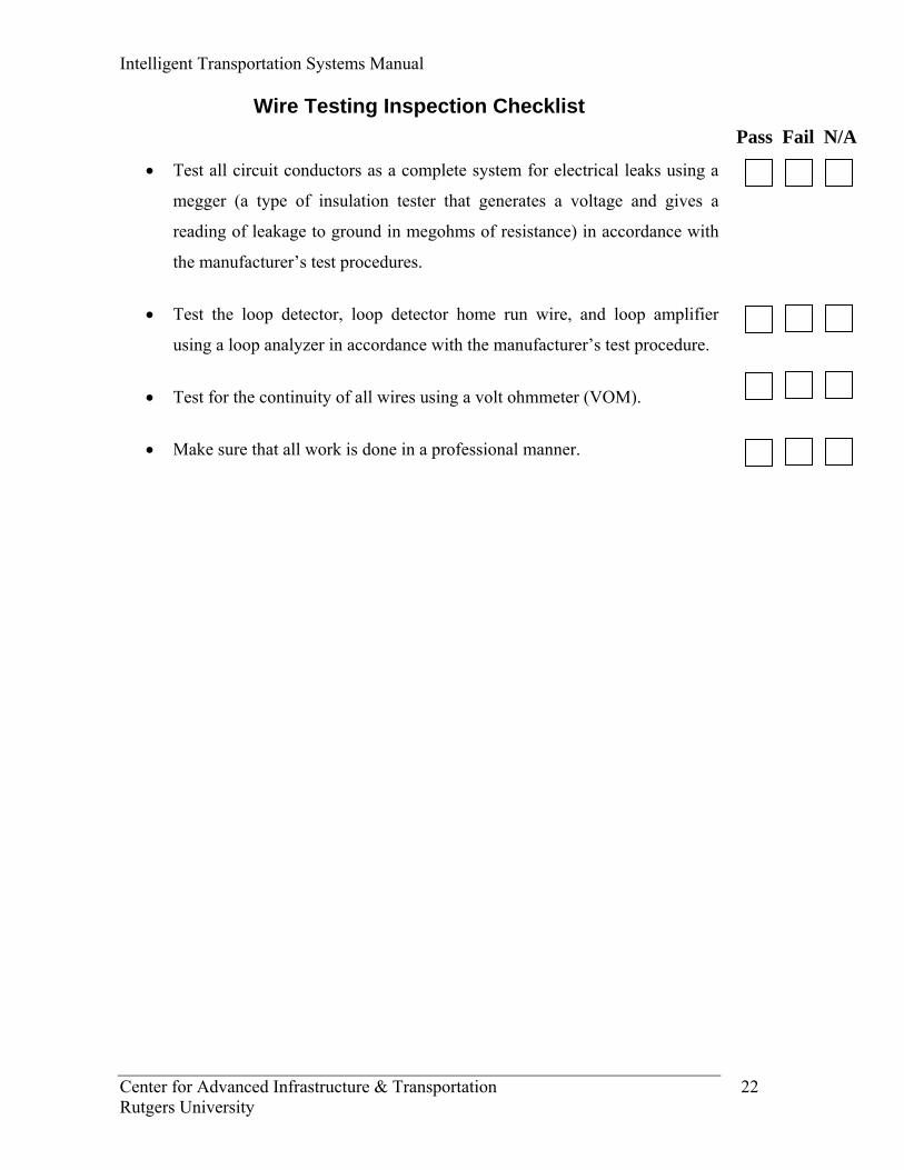
Wire Testing Inspection Checklist
• Test all circuit conductors as a complete system for electrical leaks using a
megger (a type of insulation tester that generates a voltage and gives a
reading of leakage to ground in megohms of resistance) in accordance with
the manufacturer’s test procedures.
• Test the loop detector, loop detector home run wire, and loop amplifier
using a loop analyzer in accordance with the manufacturer’s test procedure.
• Test for the continuity of all wires using a volt ohmmeter (VOM).
• Make sure that all work is done in a professional manner.
Pass Fail N/A

Intelligent Transportation Systems Manual
Center for Advanced Infrastructure & Transportation 23 Rutgers University
Communication/Field Equipment Cabinet Inspection Checklist
• Check that the cabinet is properly centered and installed on the foundation
or pole. Check that the conduit/raceway entering the cabinet (should be from
the bottom) is sealed properly with duct sealant and that the power
distribution and communication cables are properly coiled/terminated.
• Check that the following equipment is properly installed in accordance with
the plans and specifications and at the designated locations:
o high-speed communication,
o Multiplexers (MUX),
o CODEX,
o modems (data, video, voice),
o modem rack/power supply,
o fiber-optic patch panel/fan out kit,
o cabinet security devices.
• Check that the following peripheral equipment is properly installed in
accordance with standard details:
Equipment
o air conditioning,
o heater,
o fans,
o lightning protection,
o 19 in. / 23 in. EIA rack,
o air filtration,
o UPS (batteries) protection,
o Lighting/door switches,
o Ground fault circuit interrupter.
Pass Fail N/A
Intelligent Transportation Systems Manual
Center for Advanced Infrastructure & Transportation 24 Rutgers University
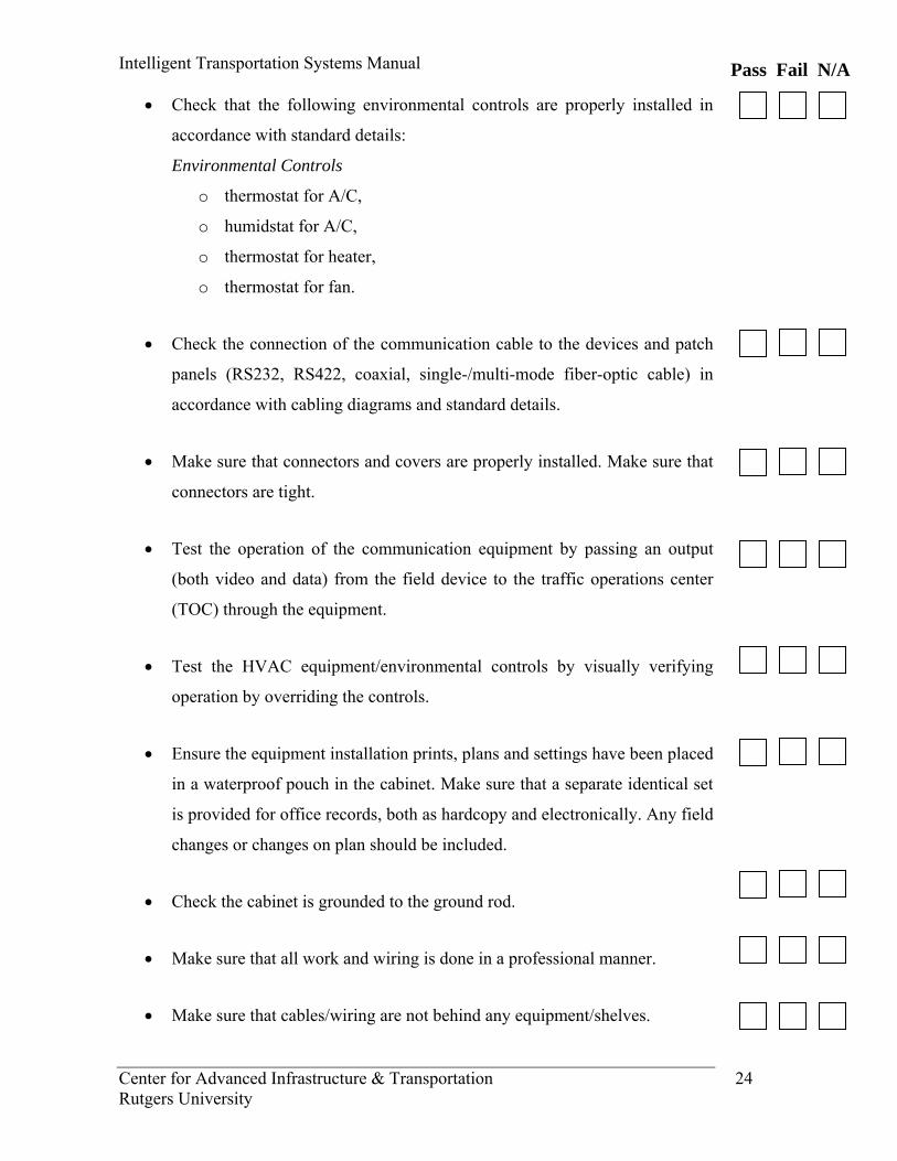
• Check that the following environmental controls are properly installed in
accordance with standard details:
Environmental Controls
o thermostat for A/C,
o humidstat for A/C,
o thermostat for heater,
o thermostat for fan.
• Check the connection of the communication cable to the devices and patch
panels (RS232, RS422, coaxial, single-/multi-mode fiber-optic cable) in
accordance with cabling diagrams and standard details.
• Make sure that connectors and covers are properly installed. Make sure that
connectors are tight.
• Test the operation of the communication equipment by passing an output
(both video and data) from the field device to the traffic operations center
(TOC) through the equipment.
• Test the HVAC equipment/environmental controls by visually verifying
operation by overriding the controls.
• Ensure the equipment installation prints, plans and settings have been placed
in a waterproof pouch in the cabinet. Make sure that a separate identical set
is provided for office records, both as hardcopy and electronically. Any field
changes or changes on plan should be included.
• Check the cabinet is grounded to the ground rod.
• Make sure that all work and wiring is done in a professional manner.
• Make sure that cables/wiring are not behind any equipment/shelves.
Pass Fail N/A
Intelligent Transportation Systems Manual
Center for Advanced Infrastructure & Transportation 25 Rutgers University
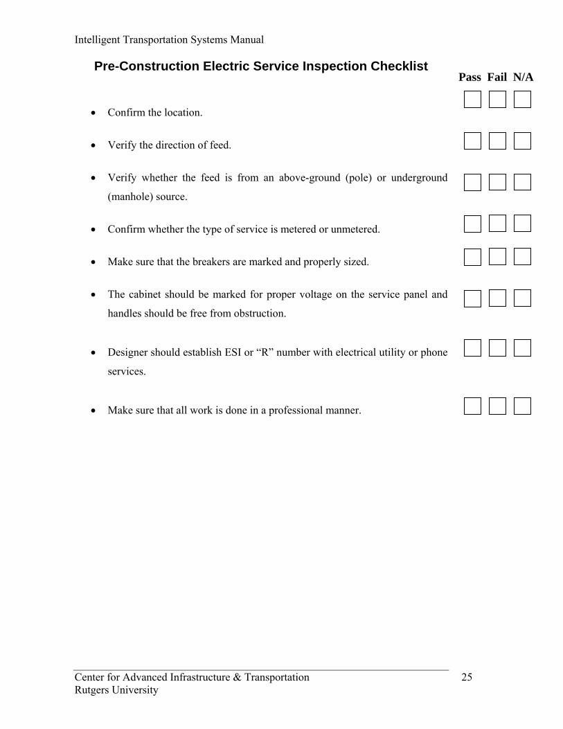
Pre-Construction Electric Service Inspection Checklist
• Confirm the location.
• Verify the direction of feed.
• Verify whether the feed is from an above-ground (pole) or underground
(manhole) source.
• Confirm whether the type of service is metered or unmetered.
• Make sure that the breakers are marked and properly sized.
• The cabinet should be marked for proper voltage on the service panel and
handles should be free from obstruction.
• Designer should establish ESI or “R” number with electrical utility or phone
services.
• Make sure that all work is done in a professional manner.
Pass Fail N/A
Intelligent Transportation Systems Manual
Center for Advanced Infrastructure & Transportation 26 Rutgers University
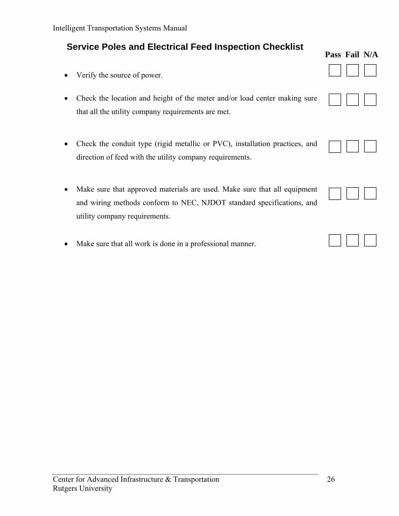
Service Poles and Electrical Feed Inspection Checklist
• Verify the source of power.
• Check the location and height of the meter and/or load center making sure
that all the utility company requirements are met.
• Check the conduit type (rigid metallic or PVC), installation practices, and
direction of feed with the utility company requirements.
• Make sure that approved materials are used. Make sure that all equipment
and wiring methods conform to NEC, NJDOT standard specifications, and
utility company requirements.
• Make sure that all work is done in a professional manner.
Pass Fail N/A

Intelligent Transportation Systems Manual
Center for Advanced Infrastructure & Transportation 27 Rutgers University
Load Center and Meter Inspection Checklist
• Check the load center and meter equipment against the approvals, shop
drawings, details, and specifications.
• Check that the load center is properly grounded and that the electrical
equipment is properly bonded.
• Identify the circuit locations on the load center door.
• The cabinet should be marked for proper voltage on the service panel.
• Handles should be free from obstruction.
• Confirm that the load center foundation is as per specifications.
• Check that strip heaters are mounted on standoffs and that proper hi-temp
wire is used for circuit conductors.
• Check all electrical (lugs) and mechanical connections on the load center
equipment to be sure that they are secure.
• See that the cabinet and enclosure doors can be fully opened without
encroachment onto Non-DOT row and that voltage warning signs are
installed.
• Make sure that all work is done in a professional manner.
Pass Fail N/A
Intelligent Transportation Systems Manual
Center for Advanced Infrastructure & Transportation 28 Rutgers University
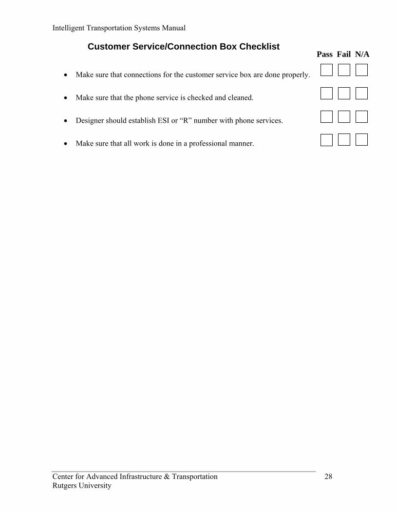
Customer Service/Connection Box Checklist
• Make sure that connections for the customer service box are done properly.
• Make sure that the phone service is checked and cleaned.
• Designer should establish ESI or “R” number with phone services.
• Make sure that all work is done in a professional manner.
Pass Fail N/A

Intelligent Transportation Systems Manual
Center for Advanced Infrastructure & Transportation 29 Rutgers University
Traffic Maintenance during Construction Checklist
• Check that all signs reflect actual prevailing conditions in the work zone.
Signs should not be prematurely installed. Remove them promptly after the
completion of work activities. Warning signs should be properly covered,
removed, relocated, or otherwise made inoperative during periods that the
contractor is not working. All the safety material should be clean and in
good condition.
• Check that all existing signs or pavement markings that conflict with the
traffic control plan are removed or covered up.
• Conduct regular inspections of all signs, pavement markings, and other
devices to ensure that they remain in good condition and that all electrical or
mechanical devices are operating satisfactorily. In particular, the work zone
should be inspected at night to ensure that all lighted and/or reflecting signs
and devices are clearly visible and functioning properly.
• The closing should be done according to MUTCD (Manual on Uniform
Traffic Control Devices) guidelines. Before closing, there should be a pre-
site inspection by the participation of resident engineer, police and traffic
coordinator of the contractor. After closing is erected, a drive-thru of the
work site should be conducted to ensure proper setup of the closure and ease
of navigation through the work zone by motorists.
• Make sure that all work is done in a professional manner.
Pass Fail N/A
Intelligent Transportation Systems Manual
Center for Advanced Infrastructure & Transportation 30 Rutgers University
“Draft”
INTELLIGENT
TRANSPORTATION SYSTEMS
(ITS) MANUAL
PREVENTIVE/ROUTINE
MAINTENANCE
GENERIC CHECKLISTS
Prepared by
Center for Advanced Infrastructure & Transportation (CAIT)
Rutgers University
June 2007
Intelligent Transportation Systems Manual
Center for Advanced Infrastructure & Transportation 31 Rutgers University
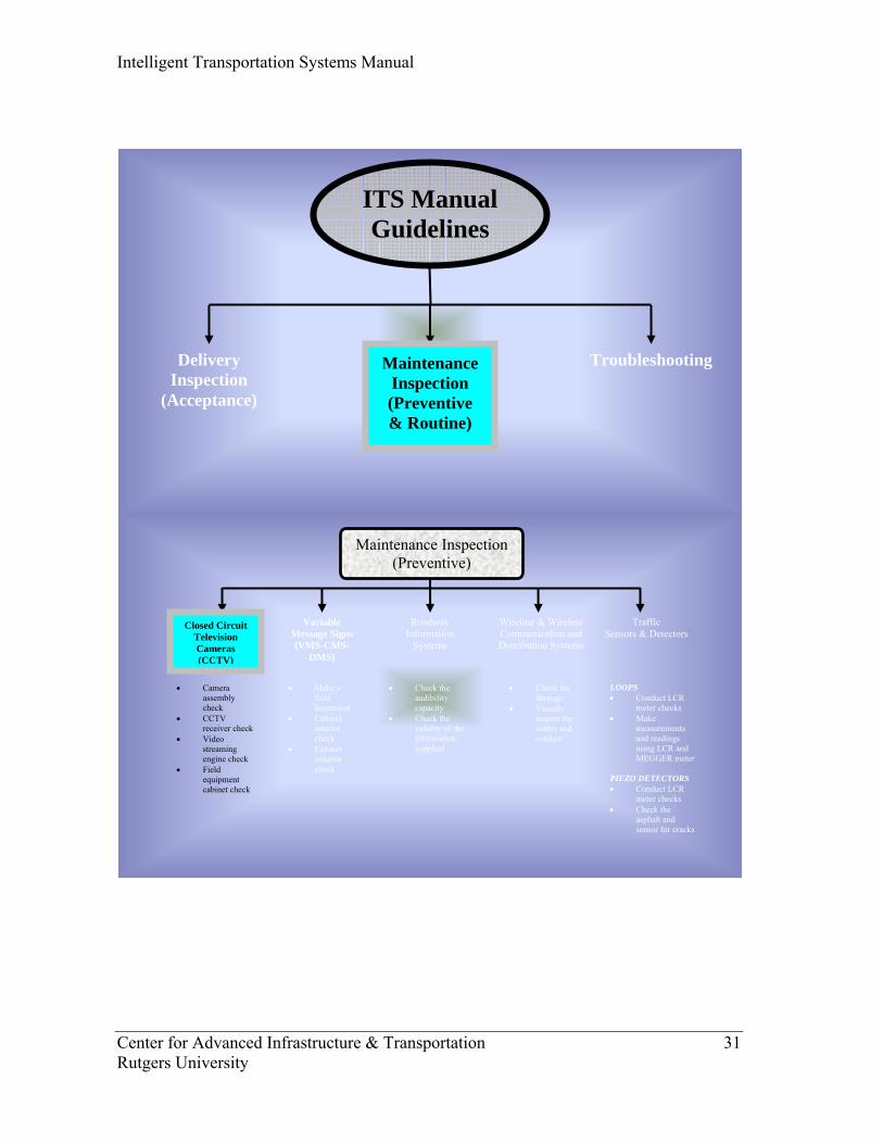
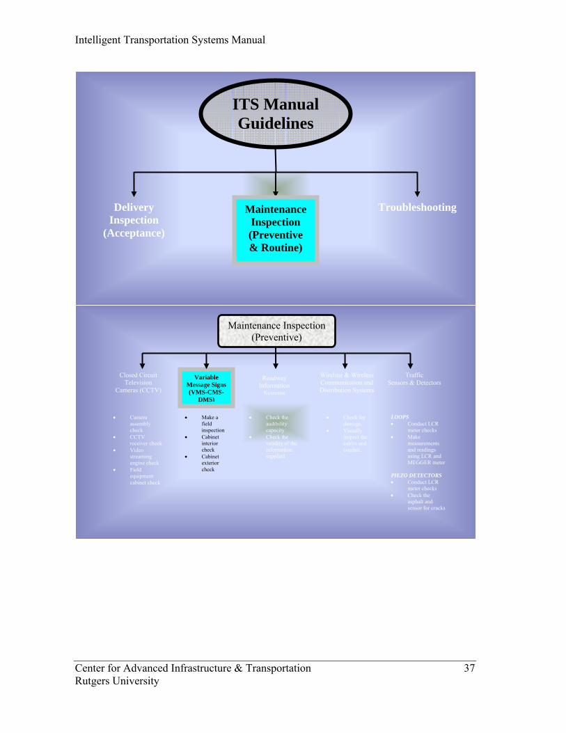
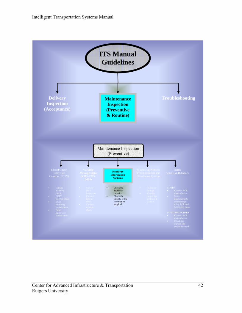
Closed Circuit Television Cameras (CCTV)
Maintenance Inspection (Preventive)
Variable Message Signs (VMS-CMS-
DMS)
Traffic Sensors & Detectors
Roadway Information
Systems
• Camera assembly check
• CCTV receiver check
• Video streaming engine check
• Field equipment cabinet check
• Make a field inspection
• Cabinet interior check
• Cabinet exterior check
• Check the audibility capacity
• Check the validity of the information supplied
LOOPS • Conduct LCR
meter checks • Make
measurements and readings using LCR and MEGGER meter
PIEZO DETECTORS • Conduct LCR
meter checks • Check the
asphalt and sensor for cracks
Wireline & Wireless Communication and Distribution Systems
• Check for damage.
• Visually inspect the cables and conduit.
ITS Manual Guidelines
Delivery Inspection
(Acceptance)
Troubleshooting Maintenance Inspection (Preventive & Routine)
Intelligent Transportation Systems Manual
Center for Advanced Infrastructure & Transportation 32 Rutgers University
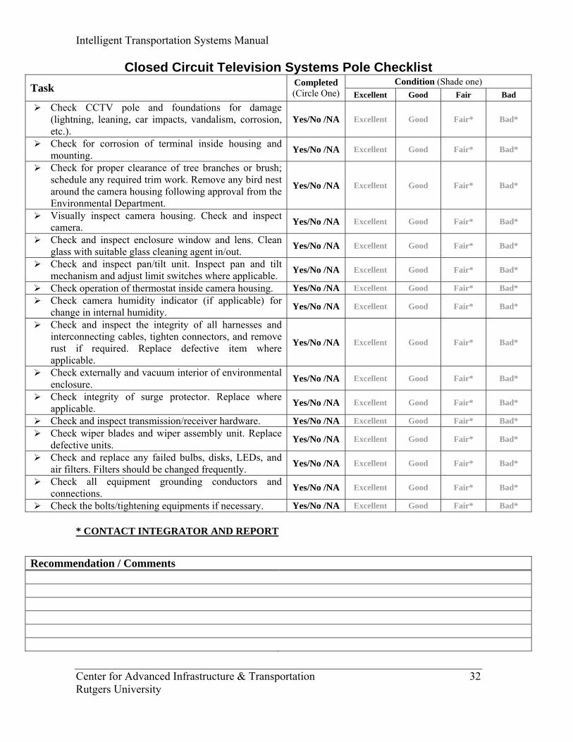
Closed Circuit Television Systems Pole Checklist Condition (Shade one) Task Completed
(Circle One) Excellent Good Fair Bad Check CCTV pole and foundations for damage
(lightning, leaning, car impacts, vandalism, corrosion, etc.).
Yes/No /NA Excellent Good Fair* Bad*
Check for corrosion of terminal inside housing and mounting. Yes/No /NA Excellent Good Fair* Bad*
Check for proper clearance of tree branches or brush; schedule any required trim work. Remove any bird nest around the camera housing following approval from the Environmental Department.
Yes/No /NA Excellent Good Fair* Bad*
Visually inspect camera housing. Check and inspect camera. Yes/No /NA Excellent Good Fair* Bad*
Check and inspect enclosure window and lens. Clean glass with suitable glass cleaning agent in/out. Yes/No /NA Excellent Good Fair* Bad*
Check and inspect pan/tilt unit. Inspect pan and tilt mechanism and adjust limit switches where applicable. Yes/No /NA Excellent Good Fair* Bad*
Check operation of thermostat inside camera housing. Yes/No /NA Excellent Good Fair* Bad* Check camera humidity indicator (if applicable) for
change in internal humidity. Yes/No /NA Excellent Good Fair* Bad*
Check and inspect the integrity of all harnesses and interconnecting cables, tighten connectors, and remove rust if required. Replace defective item where applicable.
Yes/No /NA Excellent Good Fair* Bad*
Check externally and vacuum interior of environmental enclosure. Yes/No /NA Excellent Good Fair* Bad*
Check integrity of surge protector. Replace where applicable. Yes/No /NA Excellent Good Fair* Bad*
Check and inspect transmission/receiver hardware. Yes/No /NA Excellent Good Fair* Bad* Check wiper blades and wiper assembly unit. Replace
defective units. Yes/No /NA Excellent Good Fair* Bad*
Check and replace any failed bulbs, disks, LEDs, and air filters. Filters should be changed frequently. Yes/No /NA Excellent Good Fair* Bad*
Check all equipment grounding conductors and connections. Yes/No /NA Excellent Good Fair* Bad*
Check the bolts/tightening equipments if necessary. Yes/No /NA Excellent Good Fair* Bad*
* CONTACT INTEGRATOR AND REPORT
Recommendation / Comments
Intelligent Transportation Systems Manual
Center for Advanced Infrastructure & Transportation 33 Rutgers University
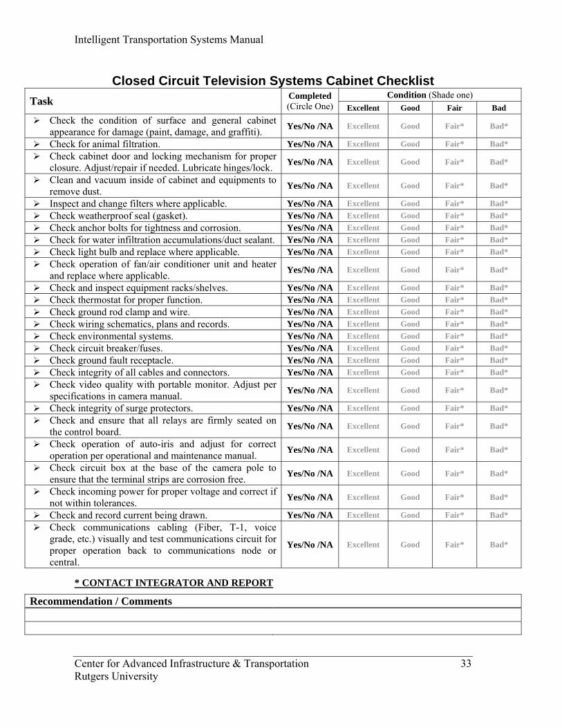
Closed Circuit Television Systems Cabinet Checklist
Condition (Shade one) Task Completed (Circle One) Excellent Good Fair Bad
Check the condition of surface and general cabinet appearance for damage (paint, damage, and graffiti). Yes/No /NA Excellent Good Fair* Bad*
Check for animal filtration. Yes/No /NA Excellent Good Fair* Bad* Check cabinet door and locking mechanism for proper
closure. Adjust/repair if needed. Lubricate hinges/lock. Yes/No /NA Excellent Good Fair* Bad*
Clean and vacuum inside of cabinet and equipments to remove dust. Yes/No /NA Excellent Good Fair* Bad*
Inspect and change filters where applicable. Yes/No /NA Excellent Good Fair* Bad* Check weatherproof seal (gasket). Yes/No /NA Excellent Good Fair* Bad* Check anchor bolts for tightness and corrosion. Yes/No /NA Excellent Good Fair* Bad* Check for water infiltration accumulations/duct sealant. Yes/No /NA Excellent Good Fair* Bad* Check light bulb and replace where applicable. Yes/No /NA Excellent Good Fair* Bad* Check operation of fan/air conditioner unit and heater
and replace where applicable. Yes/No /NA Excellent Good Fair* Bad*
Check and inspect equipment racks/shelves. Yes/No /NA Excellent Good Fair* Bad* Check thermostat for proper function. Yes/No /NA Excellent Good Fair* Bad* Check ground rod clamp and wire. Yes/No /NA Excellent Good Fair* Bad* Check wiring schematics, plans and records. Yes/No /NA Excellent Good Fair* Bad* Check environmental systems. Yes/No /NA Excellent Good Fair* Bad* Check circuit breaker/fuses. Yes/No /NA Excellent Good Fair* Bad* Check ground fault receptacle. Yes/No /NA Excellent Good Fair* Bad* Check integrity of all cables and connectors. Yes/No /NA Excellent Good Fair* Bad* Check video quality with portable monitor. Adjust per
specifications in camera manual. Yes/No /NA Excellent Good Fair* Bad*
Check integrity of surge protectors. Yes/No /NA Excellent Good Fair* Bad* Check and ensure that all relays are firmly seated on
the control board. Yes/No /NA Excellent Good Fair* Bad*
Check operation of auto-iris and adjust for correct operation per operational and maintenance manual. Yes/No /NA Excellent Good Fair* Bad*
Check circuit box at the base of the camera pole to ensure that the terminal strips are corrosion free. Yes/No /NA Excellent Good Fair* Bad*
Check incoming power for proper voltage and correct if not within tolerances. Yes/No /NA Excellent Good Fair* Bad*
Check and record current being drawn. Yes/No /NA Excellent Good Fair* Bad* Check communications cabling (Fiber, T-1, voice
grade, etc.) visually and test communications circuit for proper operation back to communications node or central.
Yes/No /NA Excellent Good Fair* Bad*
* CONTACT INTEGRATOR AND REPORT
Recommendation / Comments
Intelligent Transportation Systems Manual
Center for Advanced Infrastructure & Transportation 34 Rutgers University
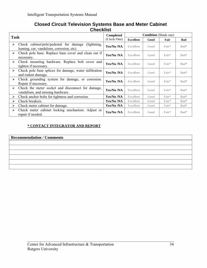
Closed Circuit Television Systems Base and Meter Cabinet Checklist
Condition (Shade one) Task Completed (Circle One) Excellent Good Fair Bad
Check cabinet/pole/pedestal for damage (lightning, leaning, car, vandalism, corrosion, etc). Yes/No /NA Excellent Good Fair* Bad*
Check pole base. Replace base cover and clean out if necessary. Yes/No /NA Excellent Good Fair* Bad*
Check mounting hardware. Replace bolt cover and tighten if necessary. Yes/No /NA Excellent Good Fair* Bad*
Check pole base splices for damage, water infiltration and rodent damage. Yes/No /NA Excellent Good Fair* Bad*
Check grounding system for damage, or corrosion. Repair if necessary. Yes/No /NA Excellent Good Fair* Bad*
Check the meter socket and disconnect for damage, vandalism, and missing hardware. Yes/No /NA Excellent Good Fair* Bad*
Check anchor bolts for tightness and corrosion. Yes/No /NA Excellent Good Fair* Bad* Check breakers. Yes/No /NA Excellent Good Fair* Bad* Check meter cabinet for damage. Yes/No /NA Excellent Good Fair* Bad* Check meter cabinet locking mechanism. Adjust or
repair if needed. Yes/No /NA Excellent Good Fair* Bad*
* CONTACT INTEGRATOR AND REPORT
Recommendation / Comments

Intelligent Transportation Systems Manual
Center for Advanced Infrastructure & Transportation 35 Rutgers University
Closed Circuit Television Conduit & Cables Checklist Condition (Shade one) Task Completed
(Circle One) Excellent Good Fair Bad Pump junction box dry if water is present remove. Yes/No /NA Excellent Good Fair* Bad* Visually inspect splice kit for water infiltration. Yes/No /NA Excellent Good Fair* Bad* Check conduit runs for settling of trench. Yes/No /NA Excellent Good Fair* Bad* Clean garbage from junction box. Yes/No /NA Excellent Good Fair* Bad* Visually inspect lugs for burning corrosion, water
infiltration and rodent damage. Yes/No /NA Excellent Good Fair* Bad*
Visually inspect cable tags. Replace or reattach if needed. Yes/No /NA Excellent Good Fair* Bad*
Visually inspect bushings for rust or damage. Yes/No /NA Excellent Good Fair* Bad* Inspect all equipment grounding conductors and
connections for integrity. Yes/No /NA Excellent Good Fair* Bad*
* CONTACT INTEGRATOR AND REPORT
Recommendation / Comments

Intelligent Transportation Systems Manual
Center for Advanced Infrastructure & Transportation 36 Rutgers University
Closed Circuit Television Checklist (At the Control Center) Condition (Shade one) Task Completed
(Circle One) Excellent Good Fair Bad Using the waveform monitor, perform the following
measurements and ensure that the results are within manufacturers specifications. Document the results.
Yes/No /NA Excellent Good Fair* Bad*
Check raw video. Yes/No /NA Excellent Good Fair* Bad* Measure peak white. Yes/No /NA Excellent Good Fair* Bad* Measure color burst. Yes/No /NA Excellent Good Fair* Bad* Measure synch pulse. Yes/No /NA Excellent Good Fair* Bad* Check integrity of all connectors. Yes/No /NA Excellent Good Fair* Bad* Check all camera video at night to determine which
cameras need back focusing. Yes/No /NA Excellent Good Fair* Bad*
Operate PTZ(Pan-Tilt-Zoom) for all functions to their extreme limits to ensure full operation and proper focus/zoom functions.
Yes/No /NA Excellent Good Fair* Bad*
* CONTACT INTEGRATOR AND REPORT
Recommendation / Comments
Intelligent Transportation Systems Manual
Center for Advanced Infrastructure & Transportation 37 Rutgers University
Closed Circuit Television
Cameras (CCTV)
Maintenance Inspection (Preventive)
Variable Message Signs (VMS-CMS-
DMS)
Traffic Sensors & Detectors
• Camera assembly check
• CCTV receiver check
• Video streaming engine check
• Field equipment cabinet check
• Make a field inspection
• Cabinet interior check
• Cabinet exterior check
• Check the audibility capacity
• Check the validity of the information supplied
LOOPS • Conduct LCR
meter checks • Make
measurements and readings using LCR and MEGGER meter
PIEZO DETECTORS • Conduct LCR
meter checks • Check the
asphalt and sensor for cracks
Wireline & Wireless Communication and Distribution Systems
• Check for damage.
• Visually inspect the cables and conduit.
Roadway Information
Systems
ITS Manual Guidelines
Delivery Inspection
(Acceptance)
Troubleshooting Maintenance Inspection (Preventive & Routine)
Intelligent Transportation Systems Manual
Center for Advanced Infrastructure & Transportation 38 Rutgers University
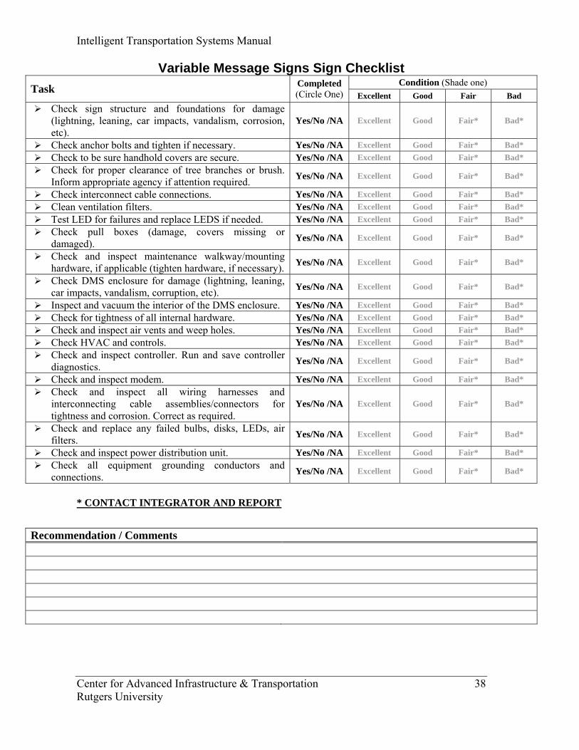
Variable Message Signs Sign Checklist Condition (Shade one) Task Completed
(Circle One) Excellent Good Fair Bad Check sign structure and foundations for damage
(lightning, leaning, car impacts, vandalism, corrosion, etc).
Yes/No /NA Excellent Good Fair* Bad*
Check anchor bolts and tighten if necessary. Yes/No /NA Excellent Good Fair* Bad* Check to be sure handhold covers are secure. Yes/No /NA Excellent Good Fair* Bad* Check for proper clearance of tree branches or brush.
Inform appropriate agency if attention required. Yes/No /NA Excellent Good Fair* Bad*
Check interconnect cable connections. Yes/No /NA Excellent Good Fair* Bad* Clean ventilation filters. Yes/No /NA Excellent Good Fair* Bad* Test LED for failures and replace LEDS if needed. Yes/No /NA Excellent Good Fair* Bad* Check pull boxes (damage, covers missing or
damaged). Yes/No /NA Excellent Good Fair* Bad*
Check and inspect maintenance walkway/mounting hardware, if applicable (tighten hardware, if necessary). Yes/No /NA Excellent Good Fair* Bad*
Check DMS enclosure for damage (lightning, leaning, car impacts, vandalism, corruption, etc). Yes/No /NA Excellent Good Fair* Bad*
Inspect and vacuum the interior of the DMS enclosure. Yes/No /NA Excellent Good Fair* Bad* Check for tightness of all internal hardware. Yes/No /NA Excellent Good Fair* Bad* Check and inspect air vents and weep holes. Yes/No /NA Excellent Good Fair* Bad* Check HVAC and controls. Yes/No /NA Excellent Good Fair* Bad* Check and inspect controller. Run and save controller
diagnostics. Yes/No /NA Excellent Good Fair* Bad*
Check and inspect modem. Yes/No /NA Excellent Good Fair* Bad* Check and inspect all wiring harnesses and
interconnecting cable assemblies/connectors for tightness and corrosion. Correct as required.
Yes/No /NA Excellent Good Fair* Bad*
Check and replace any failed bulbs, disks, LEDs, air filters. Yes/No /NA Excellent Good Fair* Bad*
Check and inspect power distribution unit. Yes/No /NA Excellent Good Fair* Bad* Check all equipment grounding conductors and
connections. Yes/No /NA Excellent Good Fair* Bad*
* CONTACT INTEGRATOR AND REPORT
Recommendation / Comments
Intelligent Transportation Systems Manual
Center for Advanced Infrastructure & Transportation 39 Rutgers University
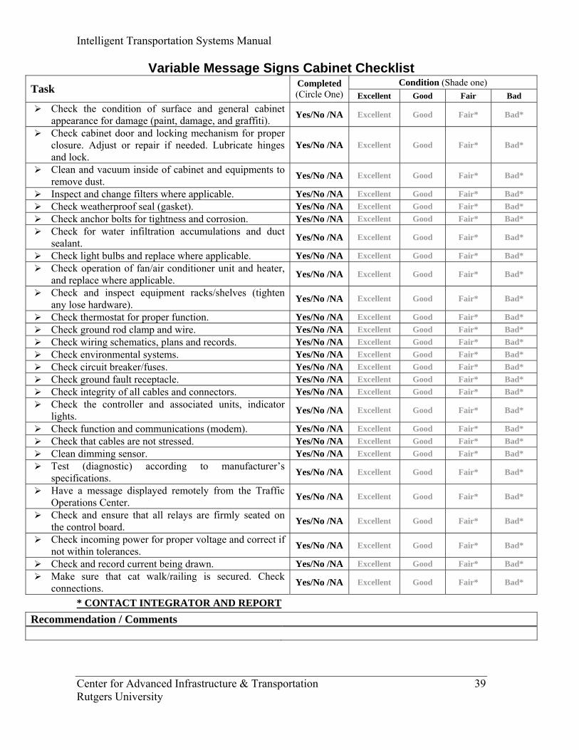
Variable Message Signs Cabinet Checklist Condition (Shade one) Task Completed
(Circle One) Excellent Good Fair Bad Check the condition of surface and general cabinet
appearance for damage (paint, damage, and graffiti). Yes/No /NA Excellent Good Fair* Bad*
Check cabinet door and locking mechanism for proper closure. Adjust or repair if needed. Lubricate hinges and lock.
Yes/No /NA Excellent Good Fair* Bad*
Clean and vacuum inside of cabinet and equipments to remove dust. Yes/No /NA Excellent Good Fair* Bad*
Inspect and change filters where applicable. Yes/No /NA Excellent Good Fair* Bad* Check weatherproof seal (gasket). Yes/No /NA Excellent Good Fair* Bad* Check anchor bolts for tightness and corrosion. Yes/No /NA Excellent Good Fair* Bad* Check for water infiltration accumulations and duct
sealant. Yes/No /NA Excellent Good Fair* Bad*
Check light bulbs and replace where applicable. Yes/No /NA Excellent Good Fair* Bad* Check operation of fan/air conditioner unit and heater,
and replace where applicable. Yes/No /NA Excellent Good Fair* Bad*
Check and inspect equipment racks/shelves (tighten any lose hardware). Yes/No /NA Excellent Good Fair* Bad*
Check thermostat for proper function. Yes/No /NA Excellent Good Fair* Bad* Check ground rod clamp and wire. Yes/No /NA Excellent Good Fair* Bad* Check wiring schematics, plans and records. Yes/No /NA Excellent Good Fair* Bad* Check environmental systems. Yes/No /NA Excellent Good Fair* Bad* Check circuit breaker/fuses. Yes/No /NA Excellent Good Fair* Bad* Check ground fault receptacle. Yes/No /NA Excellent Good Fair* Bad* Check integrity of all cables and connectors. Yes/No /NA Excellent Good Fair* Bad* Check the controller and associated units, indicator
lights. Yes/No /NA Excellent Good Fair* Bad*
Check function and communications (modem). Yes/No /NA Excellent Good Fair* Bad* Check that cables are not stressed. Yes/No /NA Excellent Good Fair* Bad* Clean dimming sensor. Yes/No /NA Excellent Good Fair* Bad* Test (diagnostic) according to manufacturer’s
specifications. Yes/No /NA Excellent Good Fair* Bad*
Have a message displayed remotely from the Traffic Operations Center. Yes/No /NA Excellent Good Fair* Bad*
Check and ensure that all relays are firmly seated on the control board. Yes/No /NA Excellent Good Fair* Bad*
Check incoming power for proper voltage and correct if not within tolerances. Yes/No /NA Excellent Good Fair* Bad*
Check and record current being drawn. Yes/No /NA Excellent Good Fair* Bad* Make sure that cat walk/railing is secured. Check
connections. Yes/No /NA Excellent Good Fair* Bad*
* CONTACT INTEGRATOR AND REPORT
Recommendation / Comments
Intelligent Transportation Systems Manual
Center for Advanced Infrastructure & Transportation 40 Rutgers University
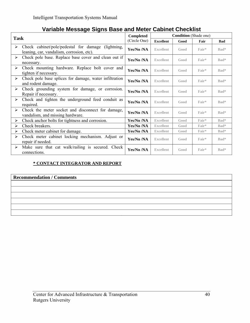
Variable Message Signs Base and Meter Cabinet Checklist Condition (Shade one) Task Completed
(Circle One) Excellent Good Fair Bad Check cabinet/pole/pedestal for damage (lightning,
leaning, car, vandalism, corrosion, etc). Yes/No /NA Excellent Good Fair* Bad*
Check pole base. Replace base cover and clean out if necessary. Yes/No /NA Excellent Good Fair* Bad*
Check mounting hardware. Replace bolt cover and tighten if necessary. Yes/No /NA Excellent Good Fair* Bad*
Check pole base splices for damage, water infiltration and rodent damage. Yes/No /NA Excellent Good Fair* Bad*
Check grounding system for damage, or corrosion. Repair if necessary. Yes/No /NA Excellent Good Fair* Bad*
Check and tighten the underground feed conduit as required. Yes/No /NA Excellent Good Fair* Bad*
Check the meter socket and disconnect for damage, vandalism, and missing hardware. Yes/No /NA Excellent Good Fair* Bad*
Check anchor bolts for tightness and corrosion. Yes/No /NA Excellent Good Fair* Bad* Check breakers. Yes/No /NA Excellent Good Fair* Bad* Check meter cabinet for damage. Yes/No /NA Excellent Good Fair* Bad* Check meter cabinet locking mechanism. Adjust or
repair if needed. Yes/No /NA Excellent Good Fair* Bad*
Make sure that cat walk/railing is secured. Check connections. Yes/No /NA Excellent Good Fair* Bad*
* CONTACT INTEGRATOR AND REPORT
Recommendation / Comments

Intelligent Transportation Systems Manual
Center for Advanced Infrastructure & Transportation 41 Rutgers University
Variable Message Signs Conduit & Cables Checklist Condition (Shade one) Task Completed
(Circle One) Excellent Good Fair Bad Check conduit runs for settling of trench. Yes/No /NA Excellent Good Fair* Bad* Visually inspect splice kit for water infiltration. Yes/No /NA Excellent Good Fair* Bad* Pump junction box dry if water is present remove. Yes/No /NA Excellent Good Fair* Bad* Clean garbage from junction box. Yes/No /NA Excellent Good Fair* Bad* Visually inspect lugs for burning corrosion, water
infiltration and rodent damage. Yes/No /NA Excellent Good Fair* Bad*
Visually inspect cable tags. Replace or reattach if needed. Yes/No /NA Excellent Good Fair* Bad*
Visually inspect bushings for rust or damage. Yes/No /NA Excellent Good Fair* Bad* Inspect all equipment grounding conductors and
connections for integrity. Yes/No /NA Excellent Good Fair* Bad*
* CONTACT INTEGRATOR AND REPORT
Recommendation / Comments
Intelligent Transportation Systems Manual
Center for Advanced Infrastructure & Transportation 42 Rutgers University
Closed Circuit Television
Cameras (CCTV)
Maintenance Inspection (Preventive)
Variable Message Signs (VMS-CMS-
DMS)
Traffic Sensors & Detectors Roadway
Information Systems
• Camera assembly check
• CCTV receiver check
• Video streaming engine check
• Field equipment cabinet check
• Make a field inspection
• Cabinet interior check
• Cabinet exterior check
• Check the audibility capacity
• Check the validity of the information supplied
LOOPS • Conduct LCR
meter checks • Make
measurements and readings using LCR and MEGGER meter
PIEZO DETECTORS • Conduct LCR
meter checks • Check the
asphalt and sensor for cracks
Wireline & Wireless Communication and Distribution Systems
• Check for damage.
• Visually inspect the cables and conduit.
ITS Manual Guidelines
Delivery Inspection
(Acceptance)
Troubleshooting Maintenance Inspection (Preventive & Routine)
Intelligent Transportation Systems Manual
Center for Advanced Infrastructure & Transportation 43 Rutgers University
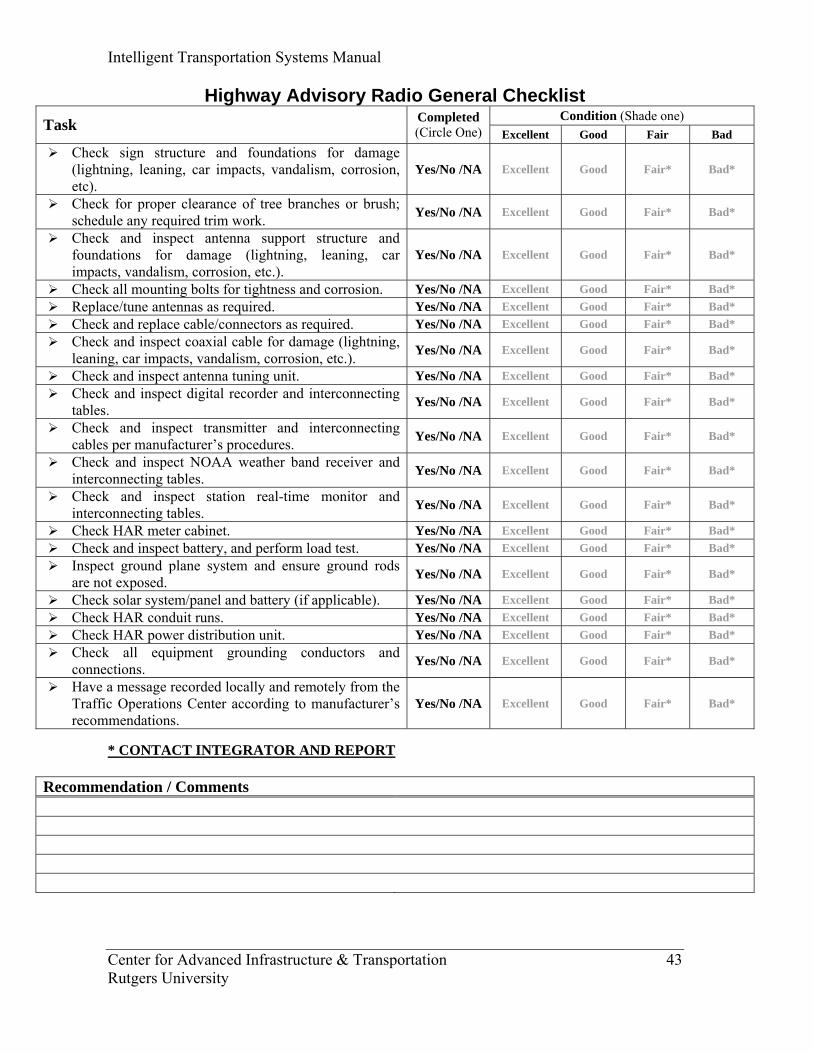
Highway Advisory Radio General Checklist Condition (Shade one) Task Completed
(Circle One) Excellent Good Fair Bad Check sign structure and foundations for damage
(lightning, leaning, car impacts, vandalism, corrosion, etc).
Yes/No /NA Excellent Good Fair* Bad*
Check for proper clearance of tree branches or brush; schedule any required trim work. Yes/No /NA Excellent Good Fair* Bad*
Check and inspect antenna support structure and foundations for damage (lightning, leaning, car impacts, vandalism, corrosion, etc.).
Yes/No /NA Excellent Good Fair* Bad*
Check all mounting bolts for tightness and corrosion. Yes/No /NA Excellent Good Fair* Bad* Replace/tune antennas as required. Yes/No /NA Excellent Good Fair* Bad* Check and replace cable/connectors as required. Yes/No /NA Excellent Good Fair* Bad* Check and inspect coaxial cable for damage (lightning,
leaning, car impacts, vandalism, corrosion, etc.). Yes/No /NA Excellent Good Fair* Bad*
Check and inspect antenna tuning unit. Yes/No /NA Excellent Good Fair* Bad* Check and inspect digital recorder and interconnecting
tables. Yes/No /NA Excellent Good Fair* Bad*
Check and inspect transmitter and interconnecting cables per manufacturer’s procedures. Yes/No /NA Excellent Good Fair* Bad*
Check and inspect NOAA weather band receiver and interconnecting tables. Yes/No /NA Excellent Good Fair* Bad*
Check and inspect station real-time monitor and interconnecting tables. Yes/No /NA Excellent Good Fair* Bad*
Check HAR meter cabinet. Yes/No /NA Excellent Good Fair* Bad* Check and inspect battery, and perform load test. Yes/No /NA Excellent Good Fair* Bad* Inspect ground plane system and ensure ground rods
are not exposed. Yes/No /NA Excellent Good Fair* Bad*
Check solar system/panel and battery (if applicable). Yes/No /NA Excellent Good Fair* Bad* Check HAR conduit runs. Yes/No /NA Excellent Good Fair* Bad* Check HAR power distribution unit. Yes/No /NA Excellent Good Fair* Bad* Check all equipment grounding conductors and
connections. Yes/No /NA Excellent Good Fair* Bad*
Have a message recorded locally and remotely from the Traffic Operations Center according to manufacturer’s recommendations.
Yes/No /NA Excellent Good Fair* Bad*
* CONTACT INTEGRATOR AND REPORT
Recommendation / Comments
Intelligent Transportation Systems Manual
Center for Advanced Infrastructure & Transportation 44 Rutgers University
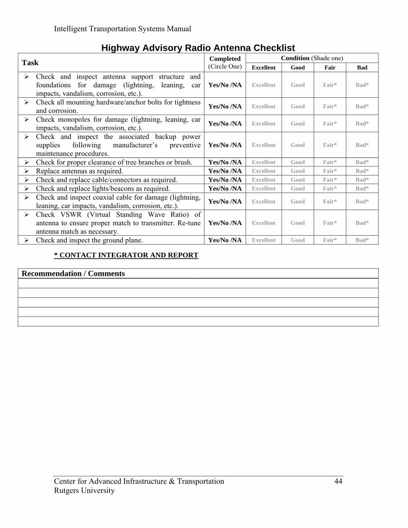
Highway Advisory Radio Antenna Checklist Condition (Shade one) Task Completed
(Circle One) Excellent Good Fair Bad Check and inspect antenna support structure and
foundations for damage (lightning, leaning, car impacts, vandalism, corrosion, etc.).
Yes/No /NA Excellent Good Fair* Bad*
Check all mounting hardware/anchor bolts for tightness and corrosion. Yes/No /NA Excellent Good Fair* Bad*
Check monopoles for damage (lightning, leaning, car impacts, vandalism, corrosion, etc.). Yes/No /NA Excellent Good Fair* Bad*
Check and inspect the associated backup power supplies following manufacturer’s preventive maintenance procedures.
Yes/No /NA Excellent Good Fair* Bad*
Check for proper clearance of tree branches or brush. Yes/No /NA Excellent Good Fair* Bad* Replace antennas as required. Yes/No /NA Excellent Good Fair* Bad* Check and replace cable/connectors as required. Yes/No /NA Excellent Good Fair* Bad* Check and replace lights/beacons as required. Yes/No /NA Excellent Good Fair* Bad* Check and inspect coaxial cable for damage (lightning,
leaning, car impacts, vandalism, corrosion, etc.). Yes/No /NA Excellent Good Fair* Bad*
Check VSWR (Virtual Standing Wave Ratio) of antenna to ensure proper match to transmitter. Re-tune antenna match as necessary.
Yes/No /NA Excellent Good Fair* Bad*
Check and inspect the ground plane. Yes/No /NA Excellent Good Fair* Bad* * CONTACT INTEGRATOR AND REPORT
Recommendation / Comments

Intelligent Transportation Systems Manual
Center for Advanced Infrastructure & Transportation 45 Rutgers University
Highway Advisory Radio Sign & Meter Cabinet Checklist Condition (Shade one) Task Completed
(Circle One) Excellent Good Fair Bad Check sign and support structure for damage (lightning,
leaning, car impacts, vandalism, corrosion, etc.). Yes/No /NA Excellent Good Fair* Bad*
Check for proper clearance of tree branches or brush; schedule any required trim work. Yes/No /NA Excellent Good Fair* Bad*
Clean fixed message static sign. Yes/No /NA Excellent Good Fair* Bad* Remove any graffiti as required. Yes/No /NA Excellent Good Fair* Bad* Clean flasher fixtures. Yes/No /NA Excellent Good Fair* Bad* Replace all damaged and/or blown bulbs. Yes/No /NA Excellent Good Fair* Bad* Check meter cabinet for damage (lightning, leaning,
car, vandalism, corrosion, etc). Yes/No /NA Excellent Good Fair* Bad*
Check meter cabinet locking mechanism. Adjust or repair if needed. Yes/No /NA Excellent Good Fair* Bad*
* CONTACT INTEGRATOR AND REPORT
Recommendation / Comments
Intelligent Transportation Systems Manual
Center for Advanced Infrastructure & Transportation 46 Rutgers University
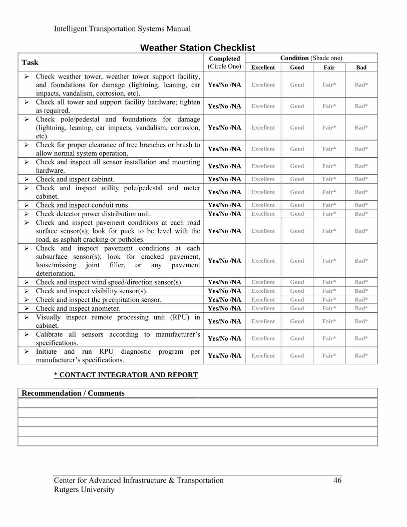
Weather Station Checklist Condition (Shade one) Task Completed
(Circle One) Excellent Good Fair Bad Check weather tower, weather tower support facility,
and foundations for damage (lightning, leaning, car impacts, vandalism, corrosion, etc).
Yes/No /NA Excellent Good Fair* Bad*
Check all tower and support facility hardware; tighten as required. Yes/No /NA Excellent Good Fair* Bad*
Check pole/pedestal and foundations for damage (lightning, leaning, car impacts, vandalism, corrosion, etc).
Yes/No /NA Excellent Good Fair* Bad*
Check for proper clearance of tree branches or brush to allow normal system operation. Yes/No /NA Excellent Good Fair* Bad*
Check and inspect all sensor installation and mounting hardware. Yes/No /NA Excellent Good Fair* Bad*
Check and inspect cabinet. Yes/No /NA Excellent Good Fair* Bad* Check and inspect utility pole/pedestal and meter
cabinet. Yes/No /NA Excellent Good Fair* Bad*
Check and inspect conduit runs. Yes/No /NA Excellent Good Fair* Bad* Check detector power distribution unit. Yes/No /NA Excellent Good Fair* Bad* Check and inspect pavement conditions at each road
surface sensor(s); look for puck to be level with the road, as asphalt cracking or potholes.
Yes/No /NA Excellent Good Fair* Bad*
Check and inspect pavement conditions at each subsurface sensor(s); look for cracked pavement, loose/missing joint filler, or any pavement deterioration.
Yes/No /NA Excellent Good Fair* Bad*
Check and inspect wind speed/direction sensor(s). Yes/No /NA Excellent Good Fair* Bad* Check and inspect visibility sensor(s). Yes/No /NA Excellent Good Fair* Bad* Check and inspect the precipitation sensor. Yes/No /NA Excellent Good Fair* Bad* Check and inspect anometer. Yes/No /NA Excellent Good Fair* Bad* Visually inspect remote processing unit (RPU) in
cabinet. Yes/No /NA Excellent Good Fair* Bad*
Calibrate all sensors according to manufacturer’s specifications. Yes/No /NA Excellent Good Fair* Bad*
Initiate and run RPU diagnostic program per manufacturer’s specifications. Yes/No /NA Excellent Good Fair* Bad*
* CONTACT INTEGRATOR AND REPORT
Recommendation / Comments
Intelligent Transportation Systems Manual
Center for Advanced Infrastructure & Transportation 47 Rutgers University
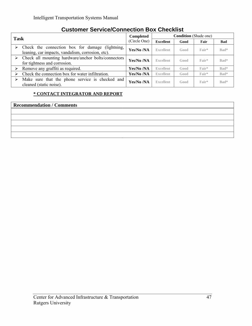
Customer Service/Connection Box Checklist Condition (Shade one) Task Completed
(Circle One) Excellent Good Fair Bad Check the connection box for damage (lightning,
leaning, car impacts, vandalism, corrosion, etc). Yes/No /NA Excellent Good Fair* Bad*
Check all mounting hardware/anchor bolts/connectors for tightness and corrosion. Yes/No /NA Excellent Good Fair* Bad*
Remove any graffiti as required. Yes/No /NA Excellent Good Fair* Bad* Check the connection box for water infiltration. Yes/No /NA Excellent Good Fair* Bad* Make sure that the phone service is checked and
cleaned (static noise). Yes/No /NA Excellent Good Fair* Bad*
* CONTACT INTEGRATOR AND REPORT
Recommendation / Comments
Intelligent Transportation Systems Manual
Center for Advanced Infrastructure & Transportation 48 Rutgers University
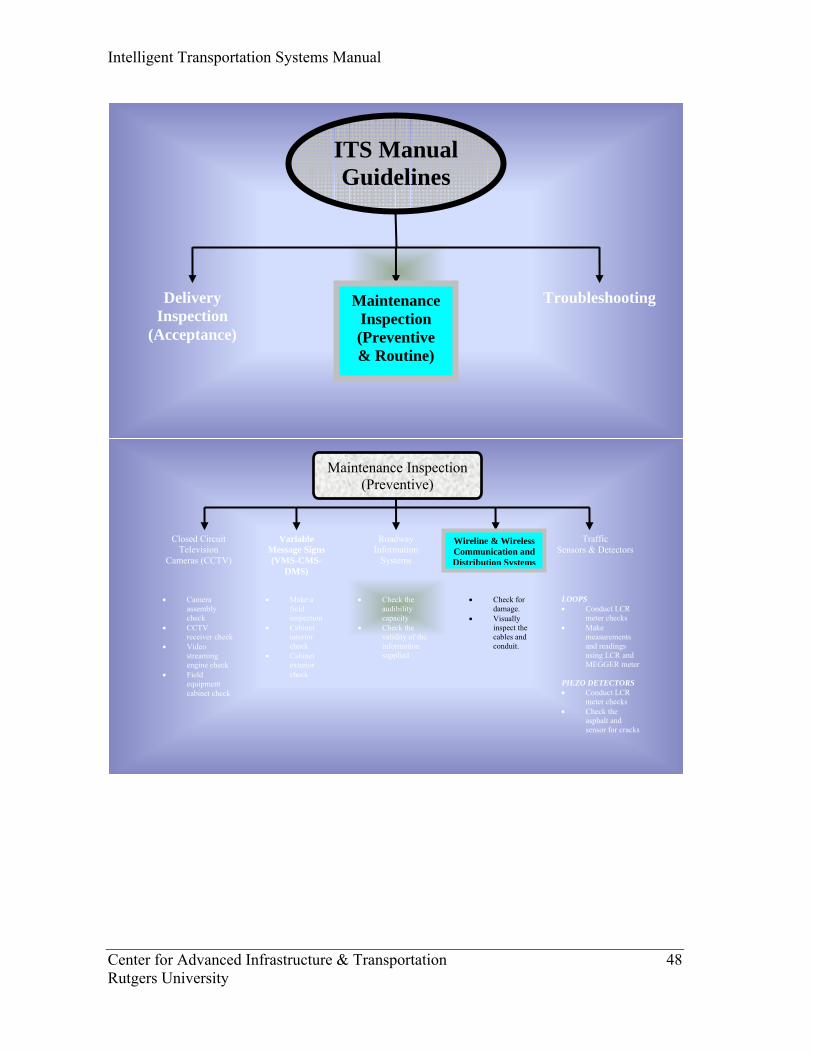
Closed Circuit Television
Cameras (CCTV)
Maintenance Inspection (Preventive)
Variable Message Signs (VMS-CMS-
DMS)
Traffic Sensors & Detectors
Roadway Information
Systems
• Camera assembly check
• CCTV receiver check
• Video streaming engine check
• Field equipment cabinet check
• Make a field inspection
• Cabinet interior check
• Cabinet exterior check
• Check the audibility capacity
• Check the validity of the information supplied
LOOPS • Conduct LCR
meter checks • Make
measurements and readings using LCR and MEGGER meter
PIEZO DETECTORS • Conduct LCR
meter checks • Check the
asphalt and sensor for cracks
Wireline & Wireless Communication and Distribution Systems
• Check for damage.
• Visually inspect the cables and conduit.
ITS Manual Guidelines
Delivery Inspection
(Acceptance)
Troubleshooting Maintenance Inspection (Preventive & Routine)
Intelligent Transportation Systems Manual
Center for Advanced Infrastructure & Transportation 49 Rutgers University
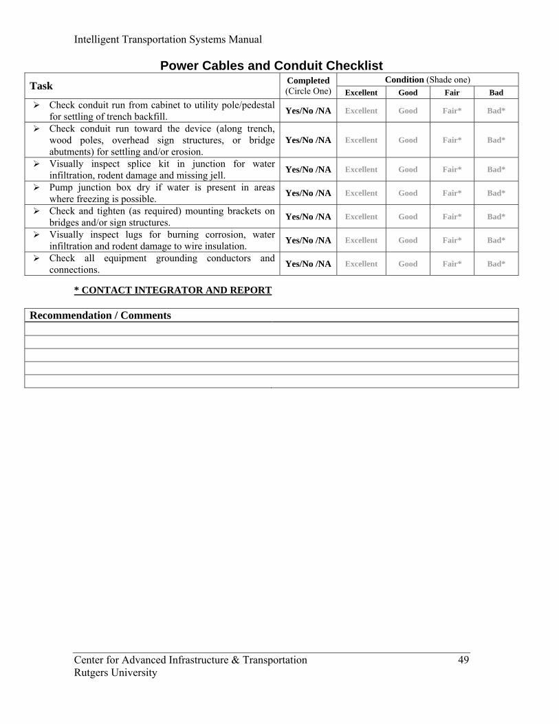
Power Cables and Conduit Checklist Condition (Shade one) Task Completed
(Circle One) Excellent Good Fair Bad Check conduit run from cabinet to utility pole/pedestal
for settling of trench backfill. Yes/No /NA Excellent Good Fair* Bad*
Check conduit run toward the device (along trench, wood poles, overhead sign structures, or bridge abutments) for settling and/or erosion.
Yes/No /NA Excellent Good Fair* Bad*
Visually inspect splice kit in junction for water infiltration, rodent damage and missing jell. Yes/No /NA Excellent Good Fair* Bad*
Pump junction box dry if water is present in areas where freezing is possible. Yes/No /NA Excellent Good Fair* Bad*
Check and tighten (as required) mounting brackets on bridges and/or sign structures. Yes/No /NA Excellent Good Fair* Bad*
Visually inspect lugs for burning corrosion, water infiltration and rodent damage to wire insulation. Yes/No /NA Excellent Good Fair* Bad*
Check all equipment grounding conductors and connections. Yes/No /NA Excellent Good Fair* Bad*
* CONTACT INTEGRATOR AND REPORT
Recommendation / Comments
Intelligent Transportation Systems Manual
Center for Advanced Infrastructure & Transportation 50 Rutgers University
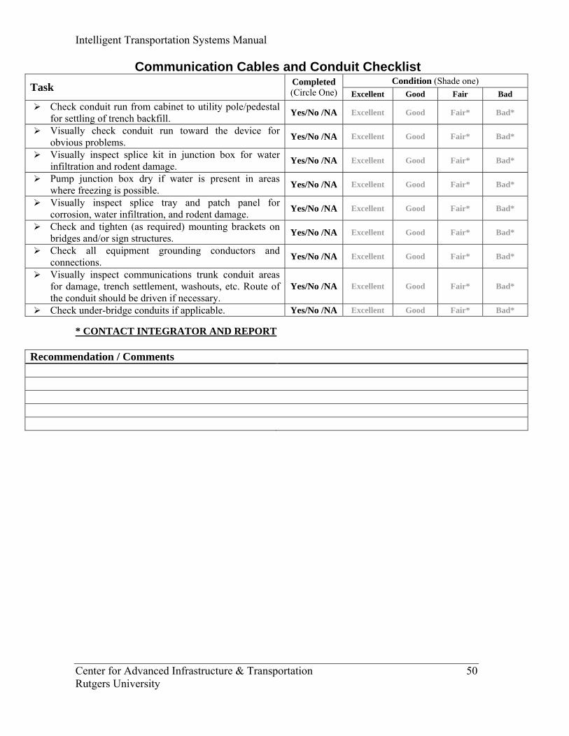
Communication Cables and Conduit Checklist Condition (Shade one) Task Completed
(Circle One) Excellent Good Fair Bad Check conduit run from cabinet to utility pole/pedestal
for settling of trench backfill. Yes/No /NA Excellent Good Fair* Bad*
Visually check conduit run toward the device for obvious problems. Yes/No /NA Excellent Good Fair* Bad*
Visually inspect splice kit in junction box for water infiltration and rodent damage. Yes/No /NA Excellent Good Fair* Bad*
Pump junction box dry if water is present in areas where freezing is possible. Yes/No /NA Excellent Good Fair* Bad*
Visually inspect splice tray and patch panel for corrosion, water infiltration, and rodent damage. Yes/No /NA Excellent Good Fair* Bad*
Check and tighten (as required) mounting brackets on bridges and/or sign structures. Yes/No /NA Excellent Good Fair* Bad*
Check all equipment grounding conductors and connections. Yes/No /NA Excellent Good Fair* Bad*
Visually inspect communications trunk conduit areas for damage, trench settlement, washouts, etc. Route of the conduit should be driven if necessary.
Yes/No /NA Excellent Good Fair* Bad*
Check under-bridge conduits if applicable. Yes/No /NA Excellent Good Fair* Bad* * CONTACT INTEGRATOR AND REPORT
Recommendation / Comments
Intelligent Transportation Systems Manual
Center for Advanced Infrastructure & Transportation 51 Rutgers University
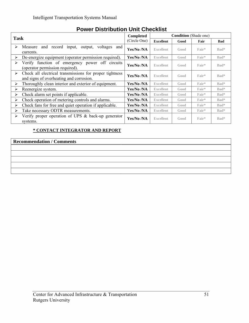
Power Distribution Unit Checklist Condition (Shade one) Task Completed
(Circle One) Excellent Good Fair Bad Measure and record input, output, voltages and
currents. Yes/No /NA Excellent Good Fair* Bad*
De-energize equipment (operator permission required). Yes/No /NA Excellent Good Fair* Bad* Verify function of emergency power off circuits
(operator permission required). Yes/No /NA Excellent Good Fair* Bad*
Check all electrical transmissions for proper tightness and signs of overheating and corrosion. Yes/No /NA Excellent Good Fair* Bad*
Thoroughly clean interior and exterior of equipment. Yes/No /NA Excellent Good Fair* Bad* Reenergize system. Yes/No /NA Excellent Good Fair* Bad* Check alarm set points if applicable. Yes/No /NA Excellent Good Fair* Bad* Check operation of metering controls and alarms. Yes/No /NA Excellent Good Fair* Bad* Check fans for free and quiet operation if applicable. Yes/No /NA Excellent Good Fair* Bad* Take necessary ODTR measurements. Yes/No /NA Excellent Good Fair* Bad* Verify proper operation of UPS & back-up generator
systems. Yes/No /NA Excellent Good Fair* Bad*
* CONTACT INTEGRATOR AND REPORT
Recommendation / Comments
Intelligent Transportation Systems Manual
Center for Advanced Infrastructure & Transportation 52 Rutgers University
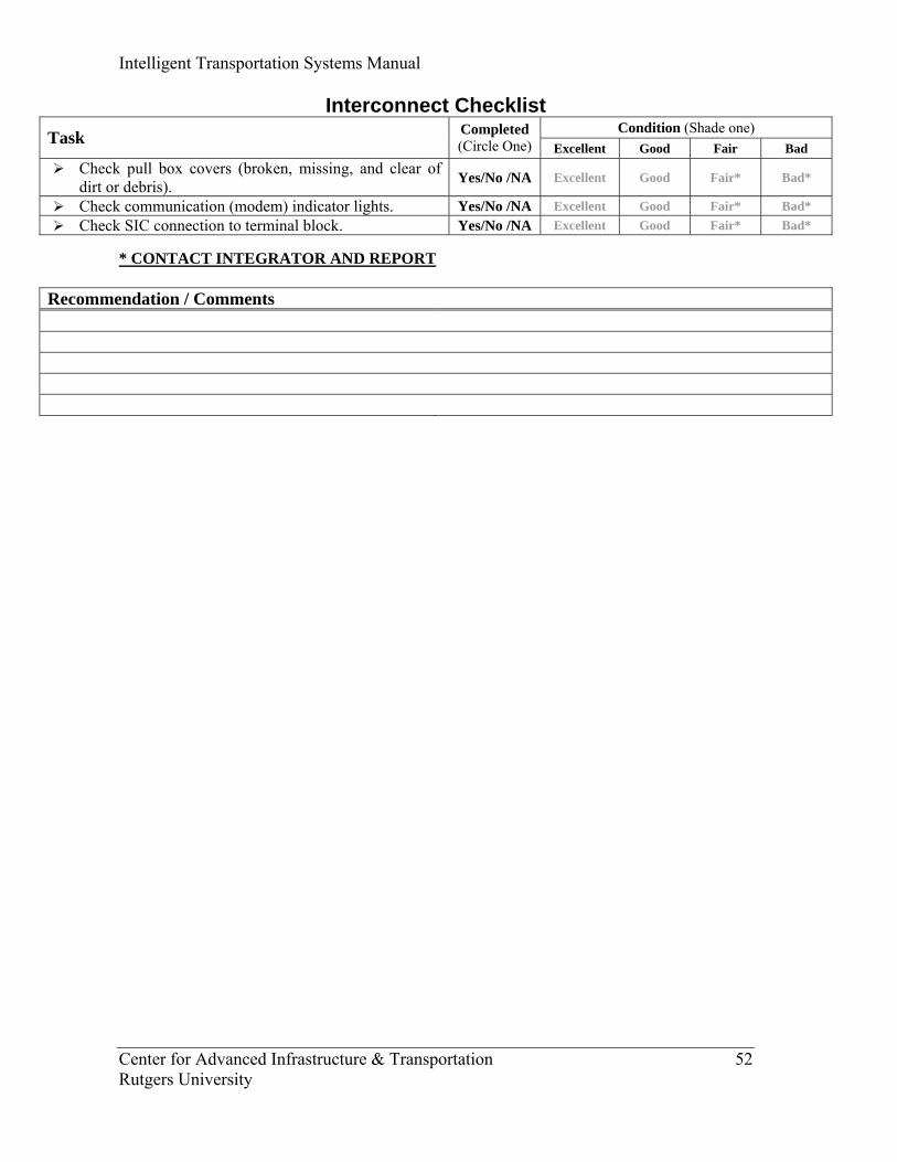
Interconnect Checklist Condition (Shade one) Task Completed
(Circle One) Excellent Good Fair Bad Check pull box covers (broken, missing, and clear of
dirt or debris). Yes/No /NA Excellent Good Fair* Bad*
Check communication (modem) indicator lights. Yes/No /NA Excellent Good Fair* Bad* Check SIC connection to terminal block. Yes/No /NA Excellent Good Fair* Bad*
* CONTACT INTEGRATOR AND REPORT
Recommendation / Comments
Intelligent Transportation Systems Manual
Center for Advanced Infrastructure & Transportation 53 Rutgers University
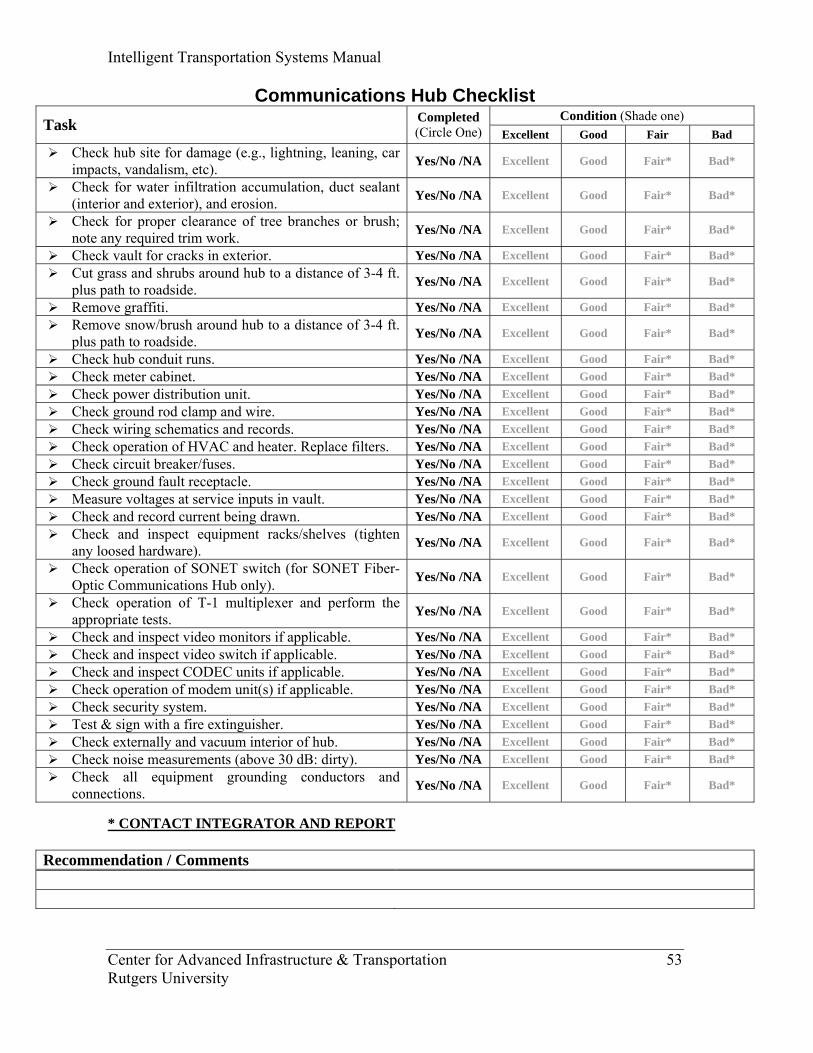
Communications Hub Checklist Condition (Shade one) Task Completed
(Circle One) Excellent Good Fair Bad Check hub site for damage (e.g., lightning, leaning, car
impacts, vandalism, etc). Yes/No /NA Excellent Good Fair* Bad*
Check for water infiltration accumulation, duct sealant (interior and exterior), and erosion. Yes/No /NA Excellent Good Fair* Bad*
Check for proper clearance of tree branches or brush; note any required trim work. Yes/No /NA Excellent Good Fair* Bad*
Check vault for cracks in exterior. Yes/No /NA Excellent Good Fair* Bad* Cut grass and shrubs around hub to a distance of 3-4 ft.
plus path to roadside. Yes/No /NA Excellent Good Fair* Bad*
Remove graffiti. Yes/No /NA Excellent Good Fair* Bad* Remove snow/brush around hub to a distance of 3-4 ft.
plus path to roadside. Yes/No /NA Excellent Good Fair* Bad*
Check hub conduit runs. Yes/No /NA Excellent Good Fair* Bad* Check meter cabinet. Yes/No /NA Excellent Good Fair* Bad* Check power distribution unit. Yes/No /NA Excellent Good Fair* Bad* Check ground rod clamp and wire. Yes/No /NA Excellent Good Fair* Bad* Check wiring schematics and records. Yes/No /NA Excellent Good Fair* Bad* Check operation of HVAC and heater. Replace filters. Yes/No /NA Excellent Good Fair* Bad* Check circuit breaker/fuses. Yes/No /NA Excellent Good Fair* Bad* Check ground fault receptacle. Yes/No /NA Excellent Good Fair* Bad* Measure voltages at service inputs in vault. Yes/No /NA Excellent Good Fair* Bad* Check and record current being drawn. Yes/No /NA Excellent Good Fair* Bad* Check and inspect equipment racks/shelves (tighten
any loosed hardware). Yes/No /NA Excellent Good Fair* Bad*
Check operation of SONET switch (for SONET Fiber-Optic Communications Hub only). Yes/No /NA Excellent Good Fair* Bad*
Check operation of T-1 multiplexer and perform the appropriate tests. Yes/No /NA Excellent Good Fair* Bad*
Check and inspect video monitors if applicable. Yes/No /NA Excellent Good Fair* Bad* Check and inspect video switch if applicable. Yes/No /NA Excellent Good Fair* Bad* Check and inspect CODEC units if applicable. Yes/No /NA Excellent Good Fair* Bad* Check operation of modem unit(s) if applicable. Yes/No /NA Excellent Good Fair* Bad* Check security system. Yes/No /NA Excellent Good Fair* Bad* Test & sign with a fire extinguisher. Yes/No /NA Excellent Good Fair* Bad* Check externally and vacuum interior of hub. Yes/No /NA Excellent Good Fair* Bad* Check noise measurements (above 30 dB: dirty). Yes/No /NA Excellent Good Fair* Bad* Check all equipment grounding conductors and
connections. Yes/No /NA Excellent Good Fair* Bad*
* CONTACT INTEGRATOR AND REPORT
Recommendation / Comments
Intelligent Transportation Systems Manual
Center for Advanced Infrastructure & Transportation 54 Rutgers University
Closed Circuit Television
Cameras (CCTV)
Maintenance Inspection (Preventive)
Variable Message Signs (VMS-CMS-
DMS)
Traffic Sensors & Detectors
Roadway Information
Systems
• Camera assembly check
• CCTV receiver check
• Video streaming engine check
• Field equipment cabinet check
• Make a field inspection
• Cabinet interior check
• Cabinet exterior check
• Check the audibility capacity
• Check the validity of the information supplied
LOOPS • Conduct LCR
meter checks • Make
measurements and readings using LCR and MEGGER meter
PIEZO DETECTORS • Conduct LCR
meter checks • Check the
asphalt and sensor for cracks
Wireline & Wireless Communication and Distribution Systems
• Check for damage.
• Visually inspect the cables and conduit.
ITS Manual Guidelines
Delivery Inspection
(Acceptance)
Troubleshooting Maintenance Inspection (Preventive & Routine)

Intelligent Transportation Systems Manual
Center for Advanced Infrastructure & Transportation 55 Rutgers University
Loop Detectors Checklist Condition (Shade one) Task Completed
(Circle One) Excellent Good Fair Bad Disconnect loop. Yes/No /NA Excellent Good Fair* Bad* With LCR meter measure and record inductance of the
loop (L=μH). Yes/No /NA Excellent Good Fair* Bad*
With LCR meter measure and record resistance (R=ohms). Yes/No /NA Excellent Good Fair* Bad*
With a MEGGER meter measure and record the insulation resistance (100 meg>). Yes/No /NA Excellent Good Fair* Bad*
If readings are outside specification, disconnect lead-in at the splice box and check all three parameters at that level.
Yes/No /NA Excellent Good Fair* Bad*
From the readings, determine whether loop or the lead-in need repair. Yes/No /NA Excellent Good Fair* Bad*
* CONTACT INTEGRATOR AND REPORT
Recommendation / Comments
Intelligent Transportation Systems Manual
Center for Advanced Infrastructure & Transportation 56 Rutgers University
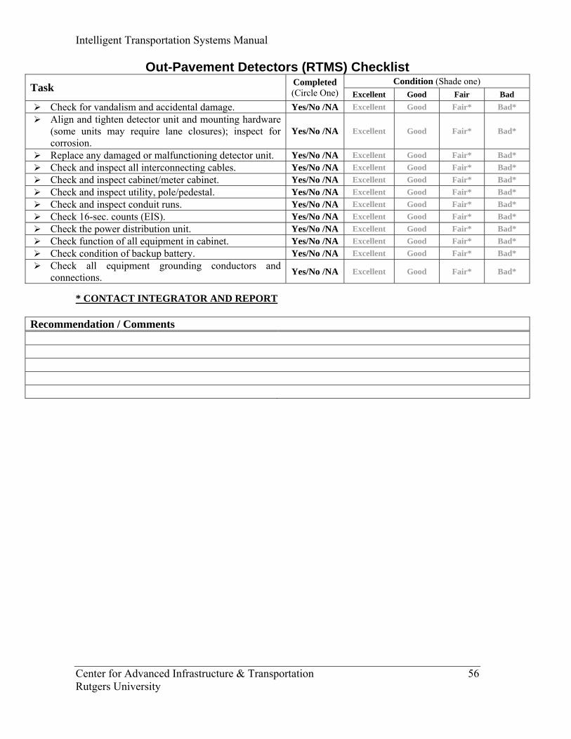
Out-Pavement Detectors (RTMS) Checklist Condition (Shade one) Task Completed
(Circle One) Excellent Good Fair Bad Check for vandalism and accidental damage. Yes/No /NA Excellent Good Fair* Bad* Align and tighten detector unit and mounting hardware
(some units may require lane closures); inspect for corrosion.
Yes/No /NA Excellent Good Fair* Bad*
Replace any damaged or malfunctioning detector unit. Yes/No /NA Excellent Good Fair* Bad* Check and inspect all interconnecting cables. Yes/No /NA Excellent Good Fair* Bad* Check and inspect cabinet/meter cabinet. Yes/No /NA Excellent Good Fair* Bad* Check and inspect utility, pole/pedestal. Yes/No /NA Excellent Good Fair* Bad* Check and inspect conduit runs. Yes/No /NA Excellent Good Fair* Bad* Check 16-sec. counts (EIS). Yes/No /NA Excellent Good Fair* Bad* Check the power distribution unit. Yes/No /NA Excellent Good Fair* Bad* Check function of all equipment in cabinet. Yes/No /NA Excellent Good Fair* Bad* Check condition of backup battery. Yes/No /NA Excellent Good Fair* Bad* Check all equipment grounding conductors and
connections. Yes/No /NA Excellent Good Fair* Bad*
* CONTACT INTEGRATOR AND REPORT
Recommendation / Comments
Intelligent Transportation Systems Manual
Center for Advanced Infrastructure & Transportation 57 Rutgers University
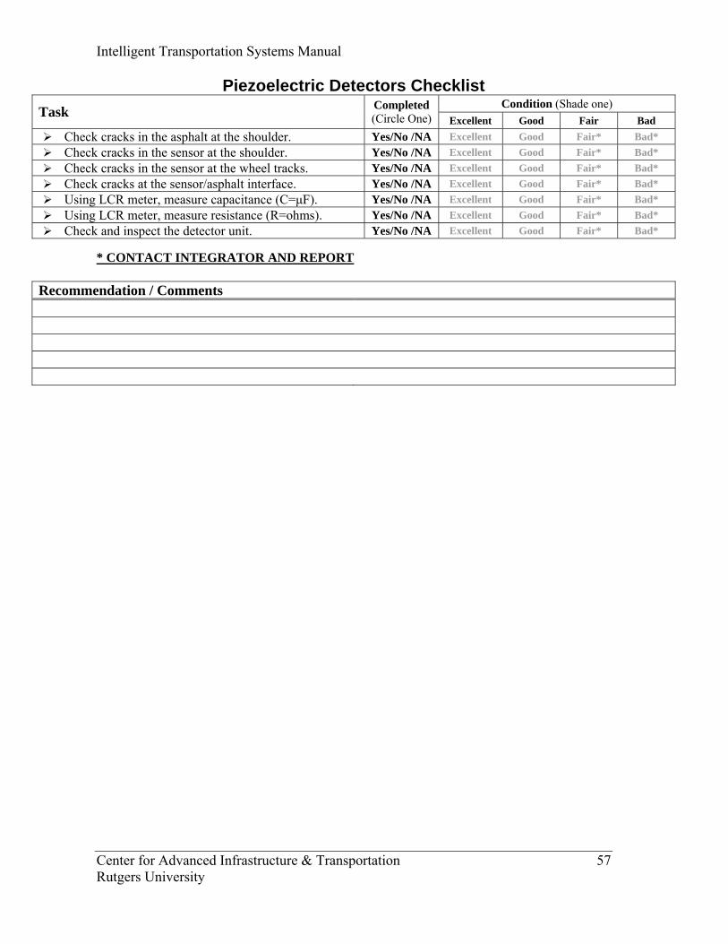
Piezoelectric Detectors Checklist Condition (Shade one) Task Completed
(Circle One) Excellent Good Fair Bad Check cracks in the asphalt at the shoulder. Yes/No /NA Excellent Good Fair* Bad* Check cracks in the sensor at the shoulder. Yes/No /NA Excellent Good Fair* Bad* Check cracks in the sensor at the wheel tracks. Yes/No /NA Excellent Good Fair* Bad* Check cracks at the sensor/asphalt interface. Yes/No /NA Excellent Good Fair* Bad* Using LCR meter, measure capacitance (C=μF). Yes/No /NA Excellent Good Fair* Bad* Using LCR meter, measure resistance (R=ohms). Yes/No /NA Excellent Good Fair* Bad* Check and inspect the detector unit. Yes/No /NA Excellent Good Fair* Bad*
* CONTACT INTEGRATOR AND REPORT
Recommendation / Comments
Intelligent Transportation Systems Manual
Center for Advanced Infrastructure & Transportation 58 Rutgers University
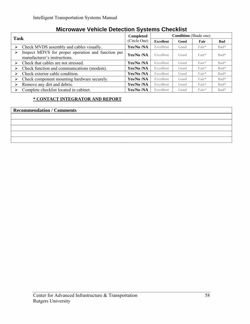
Microwave Vehicle Detection Systems Checklist Condition (Shade one) Task Completed
(Circle One) Excellent Good Fair Bad Check MVDS assembly and cables visually. Yes/No /NA Excellent Good Fair* Bad* Inspect MDVS for proper operation and function per
manufacturer’s instructions. Yes/No /NA Excellent Good Fair* Bad*
Check that cables are not stressed. Yes/No /NA Excellent Good Fair* Bad* Check function and communications (modem). Yes/No /NA Excellent Good Fair* Bad* Check exterior cable condition. Yes/No /NA Excellent Good Fair* Bad* Check component mounting hardware securely. Yes/No /NA Excellent Good Fair* Bad* Remove any dirt and debris. Yes/No /NA Excellent Good Fair* Bad* Complete checklist located in cabinet. Yes/No /NA Excellent Good Fair* Bad*
* CONTACT INTEGRATOR AND REPORT
Recommendation / Comments
Intelligent Transportation Systems Manual
Center for Advanced Infrastructure & Transportation 59 Rutgers University
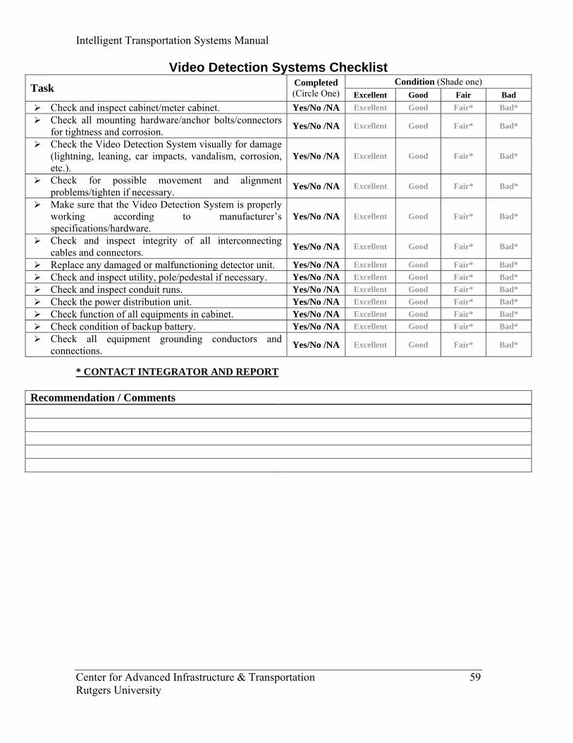
Video Detection Systems Checklist Condition (Shade one) Task Completed
(Circle One) Excellent Good Fair Bad Check and inspect cabinet/meter cabinet. Yes/No /NA Excellent Good Fair* Bad* Check all mounting hardware/anchor bolts/connectors
for tightness and corrosion. Yes/No /NA Excellent Good Fair* Bad*
Check the Video Detection System visually for damage (lightning, leaning, car impacts, vandalism, corrosion, etc.).
Yes/No /NA Excellent Good Fair* Bad*
Check for possible movement and alignment problems/tighten if necessary. Yes/No /NA Excellent Good Fair* Bad*
Make sure that the Video Detection System is properly working according to manufacturer’s specifications/hardware.
Yes/No /NA Excellent Good Fair* Bad*
Check and inspect integrity of all interconnecting cables and connectors. Yes/No /NA Excellent Good Fair* Bad*
Replace any damaged or malfunctioning detector unit. Yes/No /NA Excellent Good Fair* Bad* Check and inspect utility, pole/pedestal if necessary. Yes/No /NA Excellent Good Fair* Bad* Check and inspect conduit runs. Yes/No /NA Excellent Good Fair* Bad* Check the power distribution unit. Yes/No /NA Excellent Good Fair* Bad* Check function of all equipments in cabinet. Yes/No /NA Excellent Good Fair* Bad* Check condition of backup battery. Yes/No /NA Excellent Good Fair* Bad* Check all equipment grounding conductors and
connections. Yes/No /NA Excellent Good Fair* Bad*
* CONTACT INTEGRATOR AND REPORT
Recommendation / Comments
Intelligent Transportation Systems Manual
Center for Advanced Infrastructure & Transportation 60 Rutgers University
“Draft”
INTELLIGENT
TRANSPORTATION SYSTEMS
(ITS) MANUAL
PREVENTIVE/ROUTINE
MAINTENANCE
BRAND SPECIFIC CHECKLISTS
Prepared by
Center for Advanced Infrastructure & Transportation (CAIT)
Rutgers University
June 2007
Intelligent Transportation Systems Manual
Center for Advanced Infrastructure & Transportation 61 Rutgers University
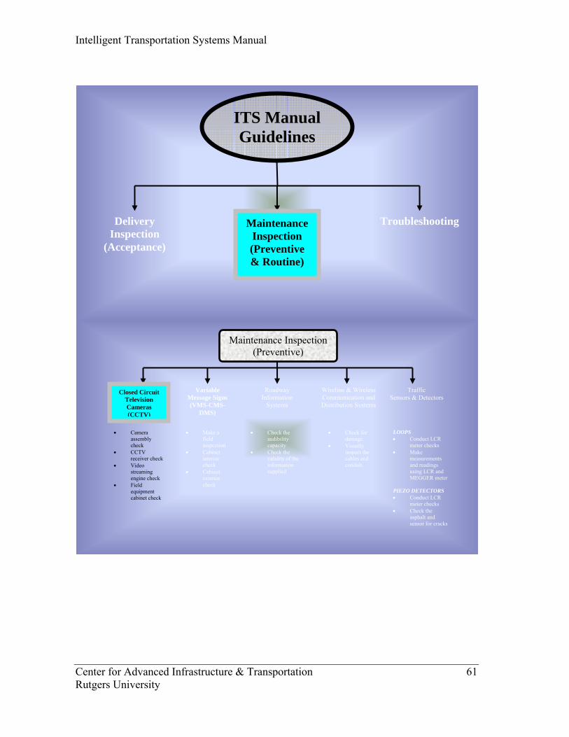
Closed Circuit Television Cameras (CCTV)
Maintenance Inspection (Preventive)
Variable Message Signs (VMS-CMS-
DMS)
Traffic Sensors & Detectors
Roadway Information
Systems
• Camera assembly check
• CCTV receiver check
• Video streaming engine check
• Field equipment cabinet check
• Make a field inspection
• Cabinet interior check
• Cabinet exterior check
• Check the audibility capacity
• Check the validity of the information supplied
LOOPS • Conduct LCR
meter checks • Make
measurements and readings using LCR and MEGGER meter
PIEZO DETECTORS • Conduct LCR
meter checks • Check the
asphalt and sensor for cracks
Wireline & Wireless Communication and Distribution Systems
• Check for damage.
• Visually inspect the cables and conduit.
ITS Manual Guidelines
Delivery Inspection
(Acceptance)
Troubleshooting Maintenance Inspection (Preventive & Routine)
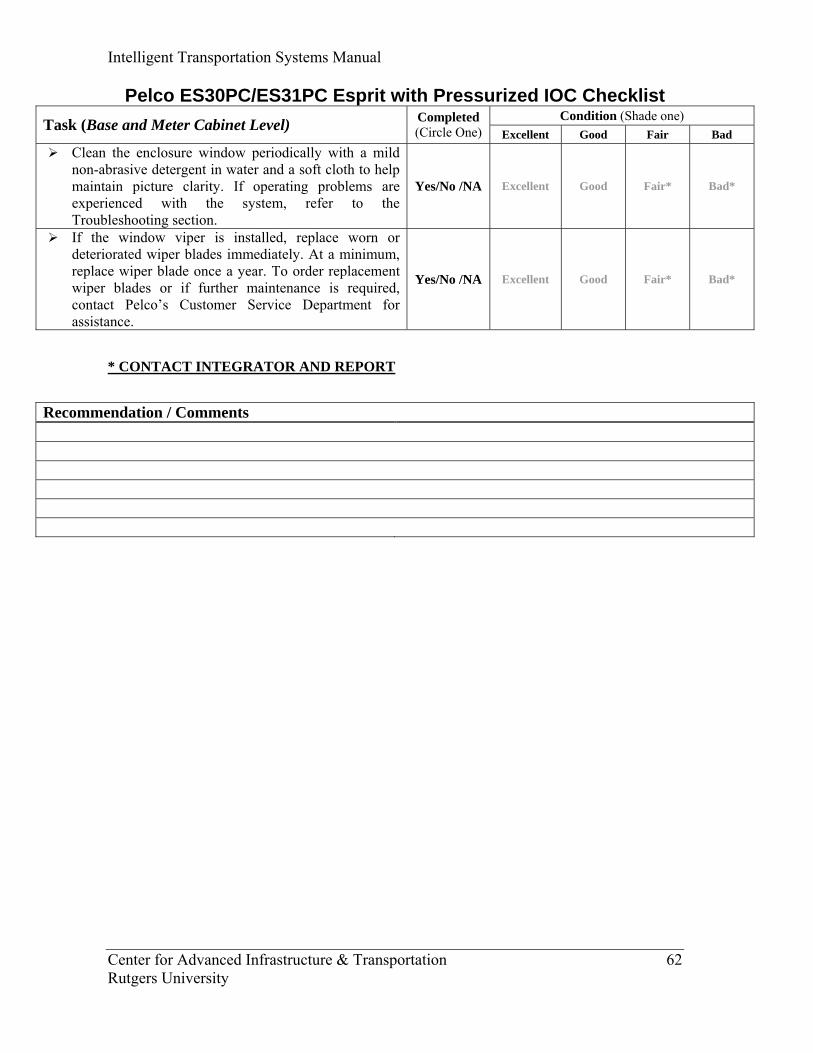
Intelligent Transportation Systems Manual
Center for Advanced Infrastructure & Transportation 62 Rutgers University
Pelco ES30PC/ES31PC Esprit with Pressurized IOC Checklist Condition (Shade one) Task (Base and Meter Cabinet Level) Completed
(Circle One) Excellent Good Fair Bad Clean the enclosure window periodically with a mild
non-abrasive detergent in water and a soft cloth to help maintain picture clarity. If operating problems are experienced with the system, refer to the Troubleshooting section.
Yes/No /NA Excellent Good Fair* Bad*
If the window viper is installed, replace worn or deteriorated wiper blades immediately. At a minimum, replace wiper blade once a year. To order replacement wiper blades or if further maintenance is required, contact Pelco’s Customer Service Department for assistance.
Yes/No /NA Excellent Good Fair* Bad*
* CONTACT INTEGRATOR AND REPORT
Recommendation / Comments
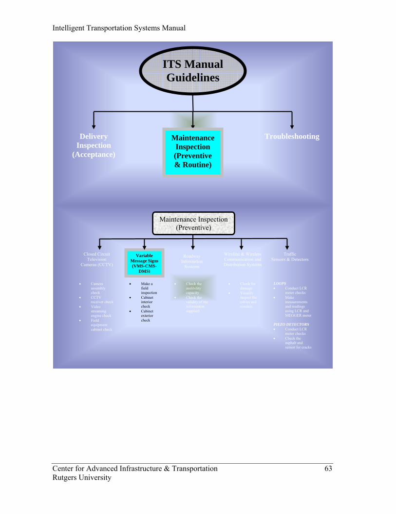
Intelligent Transportation Systems Manual
Center for Advanced Infrastructure & Transportation 63 Rutgers University
Closed Circuit Television
Cameras (CCTV)
Maintenance Inspection (Preventive)
Variable Message Signs (VMS-CMS-
DMS)
Traffic Sensors & Detectors
• Camera assembly check
• CCTV receiver check
• Video streaming engine check
• Field equipment cabinet check
• Make a field inspection
• Cabinet interior check
• Cabinet exterior check
• Check the audibility capacity
• Check the validity of the information supplied
LOOPS • Conduct LCR
meter checks • Make
measurements and readings using LCR and MEGGER meter
PIEZO DETECTORS • Conduct LCR
meter checks • Check the
asphalt and sensor for cracks
Wireline & Wireless Communication and Distribution Systems
• Check for damage.
• Visually inspect the cables and conduit.
Roadway Information
Systems
ITS Manual Guidelines
Delivery Inspection
(Acceptance)
Troubleshooting Maintenance Inspection (Preventive & Routine)
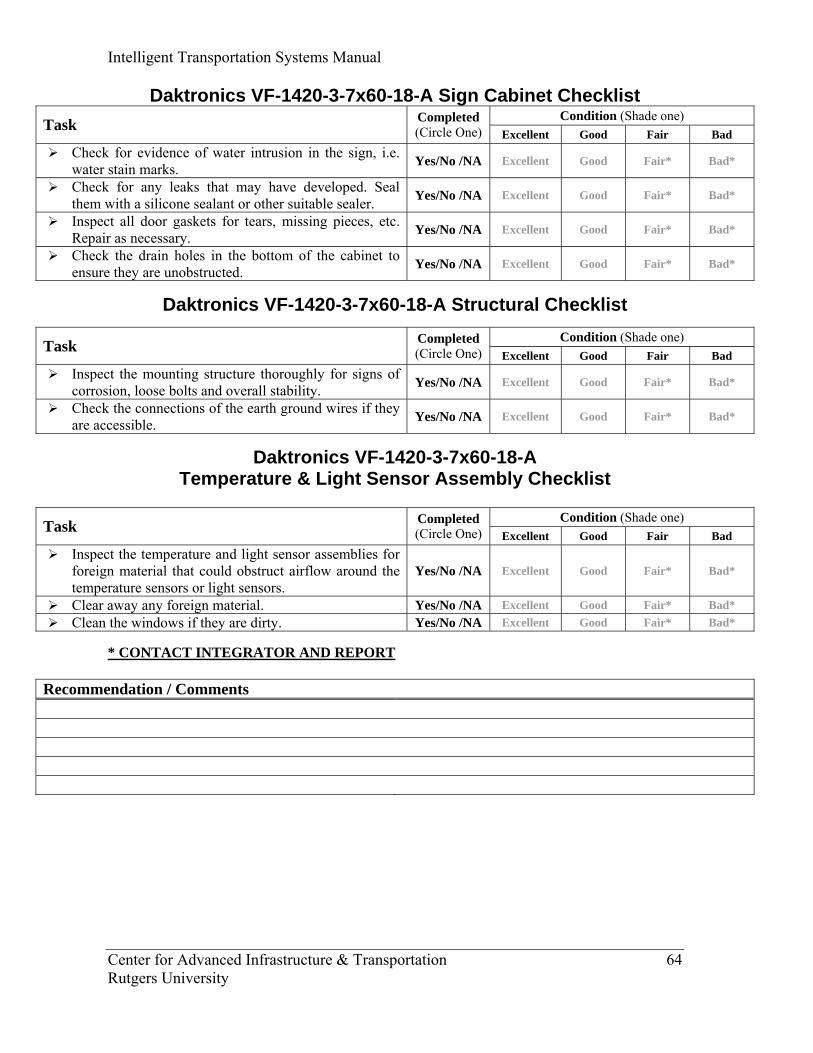
Intelligent Transportation Systems Manual
Center for Advanced Infrastructure & Transportation 64 Rutgers University
Daktronics VF-1420-3-7x60-18-A Sign Cabinet Checklist Condition (Shade one) Task Completed
(Circle One) Excellent Good Fair Bad Check for evidence of water intrusion in the sign, i.e.
water stain marks. Yes/No /NA Excellent Good Fair* Bad*
Check for any leaks that may have developed. Seal them with a silicone sealant or other suitable sealer. Yes/No /NA Excellent Good Fair* Bad*
Inspect all door gaskets for tears, missing pieces, etc. Repair as necessary. Yes/No /NA Excellent Good Fair* Bad*
Check the drain holes in the bottom of the cabinet to ensure they are unobstructed. Yes/No /NA Excellent Good Fair* Bad*
Daktronics VF-1420-3-7x60-18-A Structural Checklist
Condition (Shade one) Task Completed (Circle One) Excellent Good Fair Bad
Inspect the mounting structure thoroughly for signs of corrosion, loose bolts and overall stability. Yes/No /NA Excellent Good Fair* Bad*
Check the connections of the earth ground wires if they are accessible. Yes/No /NA Excellent Good Fair* Bad*
Daktronics VF-1420-3-7x60-18-A Temperature & Light Sensor Assembly Checklist
Condition (Shade one) Task Completed
(Circle One) Excellent Good Fair Bad Inspect the temperature and light sensor assemblies for
foreign material that could obstruct airflow around the temperature sensors or light sensors.
Yes/No /NA Excellent Good Fair* Bad*
Clear away any foreign material. Yes/No /NA Excellent Good Fair* Bad* Clean the windows if they are dirty. Yes/No /NA Excellent Good Fair* Bad*
* CONTACT INTEGRATOR AND REPORT
Recommendation / Comments
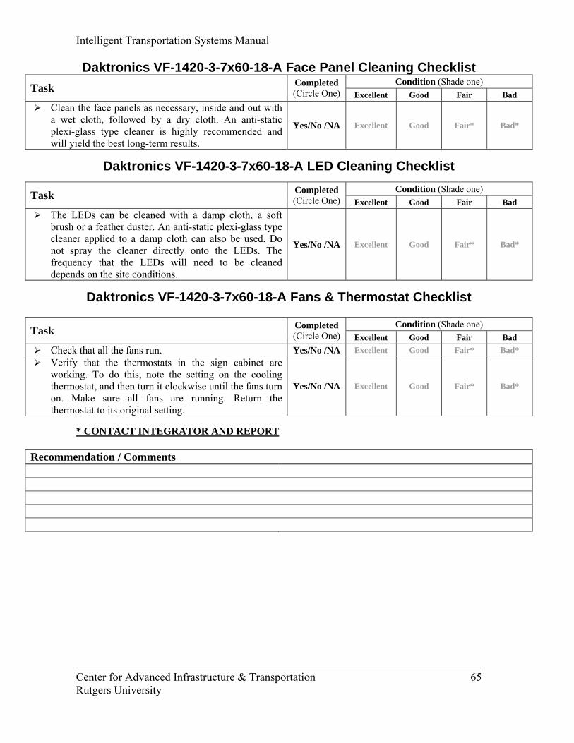
Intelligent Transportation Systems Manual
Center for Advanced Infrastructure & Transportation 65 Rutgers University
Daktronics VF-1420-3-7x60-18-A Face Panel Cleaning Checklist Condition (Shade one) Task Completed
(Circle One) Excellent Good Fair Bad Clean the face panels as necessary, inside and out with
a wet cloth, followed by a dry cloth. An anti-static plexi-glass type cleaner is highly recommended and will yield the best long-term results.
Yes/No /NA Excellent Good Fair* Bad*
Daktronics VF-1420-3-7x60-18-A LED Cleaning Checklist
Condition (Shade one) Task Completed (Circle One) Excellent Good Fair Bad
The LEDs can be cleaned with a damp cloth, a soft brush or a feather duster. An anti-static plexi-glass type cleaner applied to a damp cloth can also be used. Do not spray the cleaner directly onto the LEDs. The frequency that the LEDs will need to be cleaned depends on the site conditions.
Yes/No /NA Excellent Good Fair* Bad*
Daktronics VF-1420-3-7x60-18-A Fans & Thermostat Checklist
Condition (Shade one) Task Completed (Circle One) Excellent Good Fair Bad
Check that all the fans run. Yes/No /NA Excellent Good Fair* Bad* Verify that the thermostats in the sign cabinet are
working. To do this, note the setting on the cooling thermostat, and then turn it clockwise until the fans turn on. Make sure all fans are running. Return the thermostat to its original setting.
Yes/No /NA Excellent Good Fair* Bad*
* CONTACT INTEGRATOR AND REPORT
Recommendation / Comments
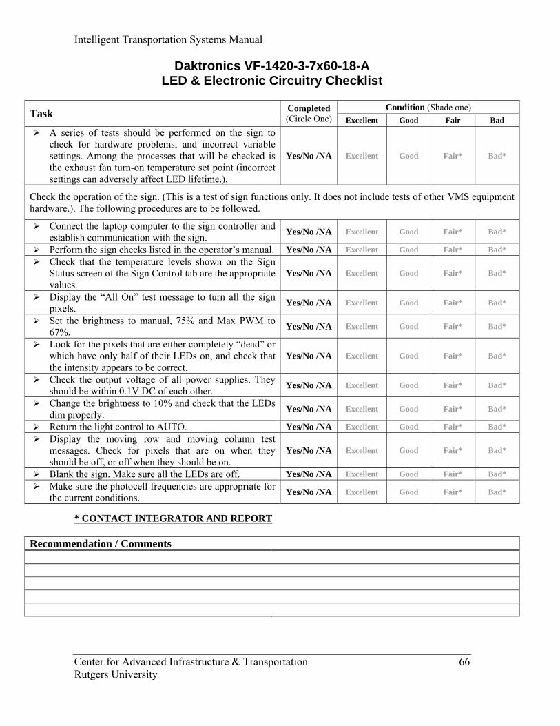
Intelligent Transportation Systems Manual
Center for Advanced Infrastructure & Transportation 66 Rutgers University
Daktronics VF-1420-3-7x60-18-A LED & Electronic Circuitry Checklist
Condition (Shade one) Task Completed
(Circle One) Excellent Good Fair Bad A series of tests should be performed on the sign to
check for hardware problems, and incorrect variable settings. Among the processes that will be checked is the exhaust fan turn-on temperature set point (incorrect settings can adversely affect LED lifetime.).
Yes/No /NA Excellent Good Fair* Bad*
Check the operation of the sign. (This is a test of sign functions only. It does not include tests of other VMS equipment hardware.). The following procedures are to be followed.
Connect the laptop computer to the sign controller and establish communication with the sign. Yes/No /NA Excellent Good Fair* Bad*
Perform the sign checks listed in the operator’s manual. Yes/No /NA Excellent Good Fair* Bad* Check that the temperature levels shown on the Sign
Status screen of the Sign Control tab are the appropriate values.
Yes/No /NA Excellent Good Fair* Bad*
Display the “All On” test message to turn all the sign pixels. Yes/No /NA Excellent Good Fair* Bad*
Set the brightness to manual, 75% and Max PWM to 67%. Yes/No /NA Excellent Good Fair* Bad*
Look for the pixels that are either completely “dead” or which have only half of their LEDs on, and check that the intensity appears to be correct.
Yes/No /NA Excellent Good Fair* Bad*
Check the output voltage of all power supplies. They should be within 0.1V DC of each other. Yes/No /NA Excellent Good Fair* Bad*
Change the brightness to 10% and check that the LEDs dim properly. Yes/No /NA Excellent Good Fair* Bad*
Return the light control to AUTO. Yes/No /NA Excellent Good Fair* Bad* Display the moving row and moving column test
messages. Check for pixels that are on when they should be off, or off when they should be on.
Yes/No /NA Excellent Good Fair* Bad*
Blank the sign. Make sure all the LEDs are off. Yes/No /NA Excellent Good Fair* Bad* Make sure the photocell frequencies are appropriate for
the current conditions. Yes/No /NA Excellent Good Fair* Bad*
* CONTACT INTEGRATOR AND REPORT
Recommendation / Comments
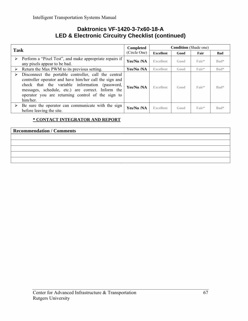
Intelligent Transportation Systems Manual
Center for Advanced Infrastructure & Transportation 67 Rutgers University
Daktronics VF-1420-3-7x60-18-A LED & Electronic Circuitry Checklist (continued)
Condition (Shade one) Task Completed
(Circle One) Excellent Good Fair Bad Perform a “Pixel Test”, and make appropriate repairs if
any pixels appear to be bad. Yes/No /NA Excellent Good Fair* Bad*
Return the Max PWM to its previous setting. Yes/No /NA Excellent Good Fair* Bad* Disconnect the portable controller, call the central
controller operator and have him/her call the sign and check that the variable information (password, messages, schedule, etc.) are correct. Inform the operator you are returning control of the sign to him/her.
Yes/No /NA Excellent Good Fair* Bad*
Be sure the operator can communicate with the sign before leaving the site. Yes/No /NA Excellent Good Fair* Bad*
* CONTACT INTEGRATOR AND REPORT
Recommendation / Comments
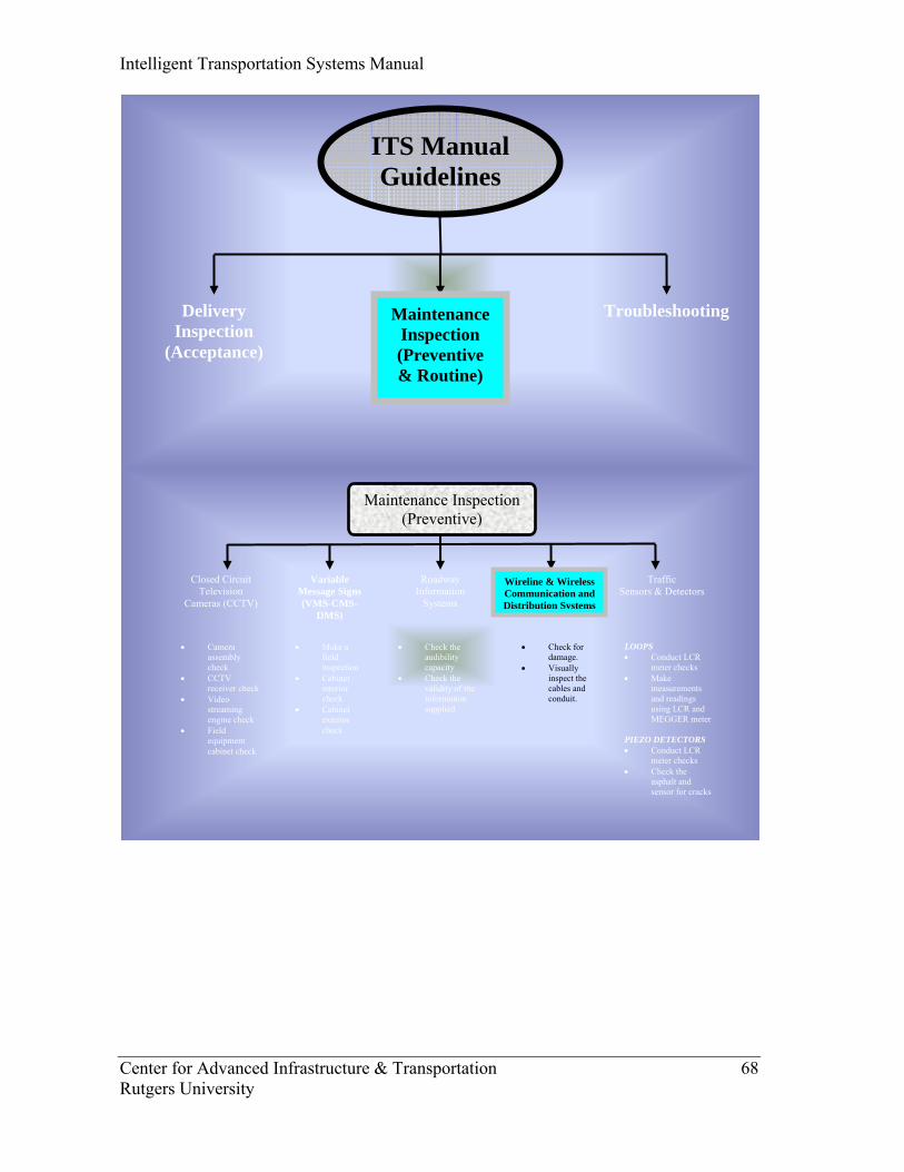
Intelligent Transportation Systems Manual
Center for Advanced Infrastructure & Transportation 68 Rutgers University
Closed Circuit Television
Cameras (CCTV)
Maintenance Inspection (Preventive)
Variable Message Signs (VMS-CMS-
DMS)
Traffic Sensors & Detectors
Roadway Information
Systems
• Camera assembly check
• CCTV receiver check
• Video streaming engine check
• Field equipment cabinet check
• Make a field inspection
• Cabinet interior check
• Cabinet exterior check
• Check the audibility capacity
• Check the validity of the information supplied
LOOPS • Conduct LCR
meter checks • Make
measurements and readings using LCR and MEGGER meter
PIEZO DETECTORS • Conduct LCR
meter checks • Check the
asphalt and sensor for cracks
Wireline & Wireless Communication and Distribution Systems
• Check for damage.
• Visually inspect the cables and conduit.
ITS Manual Guidelines
Delivery Inspection
(Acceptance)
Troubleshooting Maintenance Inspection (Preventive & Routine)
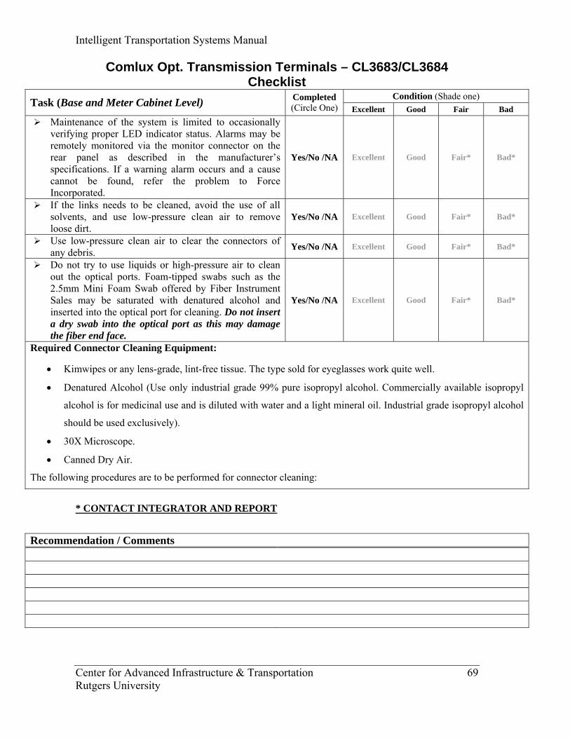
Intelligent Transportation Systems Manual
Center for Advanced Infrastructure & Transportation 69 Rutgers University
Comlux Opt. Transmission Terminals – CL3683/CL3684 Checklist
Condition (Shade one) Task (Base and Meter Cabinet Level) Completed (Circle One) Excellent Good Fair Bad
Maintenance of the system is limited to occasionally verifying proper LED indicator status. Alarms may be remotely monitored via the monitor connector on the rear panel as described in the manufacturer’s specifications. If a warning alarm occurs and a cause cannot be found, refer the problem to Force Incorporated.
Yes/No /NA Excellent Good Fair* Bad*
If the links needs to be cleaned, avoid the use of all solvents, and use low-pressure clean air to remove loose dirt.
Yes/No /NA Excellent Good Fair* Bad*
Use low-pressure clean air to clear the connectors of any debris. Yes/No /NA Excellent Good Fair* Bad*
Do not try to use liquids or high-pressure air to clean out the optical ports. Foam-tipped swabs such as the 2.5mm Mini Foam Swab offered by Fiber Instrument Sales may be saturated with denatured alcohol and inserted into the optical port for cleaning. Do not insert a dry swab into the optical port as this may damage the fiber end face.
Yes/No /NA Excellent Good Fair* Bad*
Required Connector Cleaning Equipment:
• Kimwipes or any lens-grade, lint-free tissue. The type sold for eyeglasses work quite well.
• Denatured Alcohol (Use only industrial grade 99% pure isopropyl alcohol. Commercially available isopropyl
alcohol is for medicinal use and is diluted with water and a light mineral oil. Industrial grade isopropyl alcohol
should be used exclusively).
• 30X Microscope.
• Canned Dry Air.
The following procedures are to be performed for connector cleaning:
* CONTACT INTEGRATOR AND REPORT
Recommendation / Comments
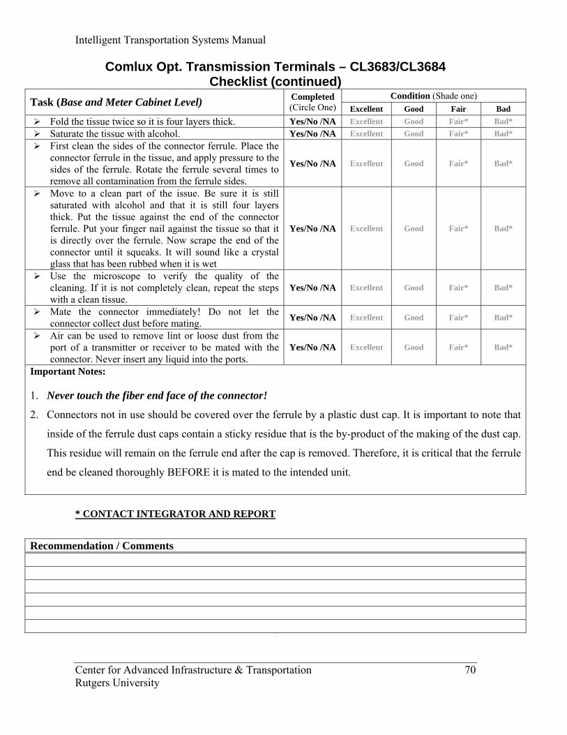
Intelligent Transportation Systems Manual
Center for Advanced Infrastructure & Transportation 70 Rutgers University
Comlux Opt. Transmission Terminals – CL3683/CL3684 Checklist (continued)
Condition (Shade one) Task (Base and Meter Cabinet Level) Completed (Circle One) Excellent Good Fair Bad
Fold the tissue twice so it is four layers thick. Yes/No /NA Excellent Good Fair* Bad* Saturate the tissue with alcohol. Yes/No /NA Excellent Good Fair* Bad* First clean the sides of the connector ferrule. Place the
connector ferrule in the tissue, and apply pressure to the sides of the ferrule. Rotate the ferrule several times to remove all contamination from the ferrule sides.
Yes/No /NA Excellent Good Fair* Bad*
Move to a clean part of the issue. Be sure it is still saturated with alcohol and that it is still four layers thick. Put the tissue against the end of the connector ferrule. Put your finger nail against the tissue so that it is directly over the ferrule. Now scrape the end of the connector until it squeaks. It will sound like a crystal glass that has been rubbed when it is wet
Yes/No /NA Excellent Good Fair* Bad*
Use the microscope to verify the quality of the cleaning. If it is not completely clean, repeat the steps with a clean tissue.
Yes/No /NA Excellent Good Fair* Bad*
Mate the connector immediately! Do not let the connector collect dust before mating. Yes/No /NA Excellent Good Fair* Bad*
Air can be used to remove lint or loose dust from the port of a transmitter or receiver to be mated with the connector. Never insert any liquid into the ports.
Yes/No /NA Excellent Good Fair* Bad*
Important Notes: 1. Never touch the fiber end face of the connector!
2. Connectors not in use should be covered over the ferrule by a plastic dust cap. It is important to note that
inside of the ferrule dust caps contain a sticky residue that is the by-product of the making of the dust cap.
This residue will remain on the ferrule end after the cap is removed. Therefore, it is critical that the ferrule
end be cleaned thoroughly BEFORE it is mated to the intended unit.
* CONTACT INTEGRATOR AND REPORT
Recommendation / Comments
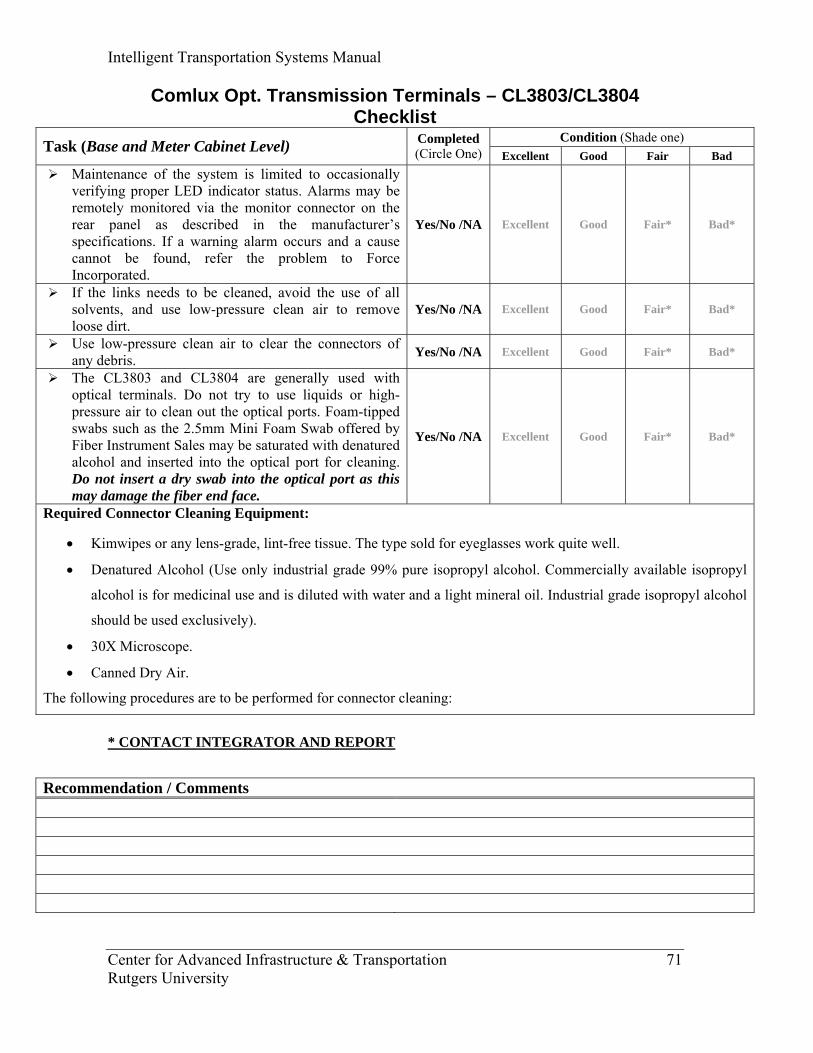
Intelligent Transportation Systems Manual
Center for Advanced Infrastructure & Transportation 71 Rutgers University
Comlux Opt. Transmission Terminals – CL3803/CL3804 Checklist
Condition (Shade one) Task (Base and Meter Cabinet Level) Completed (Circle One) Excellent Good Fair Bad
Maintenance of the system is limited to occasionally verifying proper LED indicator status. Alarms may be remotely monitored via the monitor connector on the rear panel as described in the manufacturer’s specifications. If a warning alarm occurs and a cause cannot be found, refer the problem to Force Incorporated.
Yes/No /NA Excellent Good Fair* Bad*
If the links needs to be cleaned, avoid the use of all solvents, and use low-pressure clean air to remove loose dirt.
Yes/No /NA Excellent Good Fair* Bad*
Use low-pressure clean air to clear the connectors of any debris. Yes/No /NA Excellent Good Fair* Bad*
The CL3803 and CL3804 are generally used with optical terminals. Do not try to use liquids or high-pressure air to clean out the optical ports. Foam-tipped swabs such as the 2.5mm Mini Foam Swab offered by Fiber Instrument Sales may be saturated with denatured alcohol and inserted into the optical port for cleaning. Do not insert a dry swab into the optical port as this may damage the fiber end face.
Yes/No /NA Excellent Good Fair* Bad*
Required Connector Cleaning Equipment:
• Kimwipes or any lens-grade, lint-free tissue. The type sold for eyeglasses work quite well.
• Denatured Alcohol (Use only industrial grade 99% pure isopropyl alcohol. Commercially available isopropyl
alcohol is for medicinal use and is diluted with water and a light mineral oil. Industrial grade isopropyl alcohol
should be used exclusively).
• 30X Microscope.
• Canned Dry Air.
The following procedures are to be performed for connector cleaning:
* CONTACT INTEGRATOR AND REPORT
Recommendation / Comments

Intelligent Transportation Systems Manual
Center for Advanced Infrastructure & Transportation 72 Rutgers University
Comlux Opt. Transmission Terminals – CL3803/CL3804 Checklist (continued)
Condition (Shade one) Task (Base and Meter Cabinet Level) Completed (Circle One) Excellent Good Fair Bad
Fold the tissue twice so it is four layers thick. Yes/No /NA Excellent Good Fair* Bad* Saturate the tissue with alcohol. Yes/No /NA Excellent Good Fair* Bad* First clean the sides of the connector ferrule. Place the
connector ferrule in the tissue, and apply pressure to the sides of the ferrule. Rotate the ferrule several times to remove all contamination from the ferrule sides.
Yes/No /NA Excellent Good Fair* Bad*
Move to a clean part of the issue. Be sure it is still saturated with alcohol and that it is still four layers thick. Put the tissue against the end of the connector ferrule. Put your finger nail against the tissue so that it is directly over the ferrule. Now scrape the end of the connector until it squeaks. It will sound like a crystal glass that has been rubbed when it is wet
Yes/No /NA Excellent Good Fair* Bad*
Use the microscope to verify the quality of the cleaning. If it is not completely clean, repeat the steps with a clean tissue.
Yes/No /NA Excellent Good Fair* Bad*
Mate the connector immediately! Do not let the connector collect dust before mating. Yes/No /NA Excellent Good Fair* Bad*
Air can be used to remove lint or loose dust from the port of a transmitter or receiver to be mated with the connector. Never insert any liquid into the ports.
Yes/No /NA Excellent Good Fair* Bad*
Important Notes: 3. Never touch the fiber end face of the connector!
4. Connectors not in use should be covered over the ferrule by a plastic dust cap. It is important to note that
inside of the ferrule dust caps contain a sticky residue that is the by-product of the making of the dust cap.
This residue will remain on the ferrule end after the cap is removed. Therefore, it is critical that the ferrule
end be cleaned thoroughly BEFORE it is mated to the intended unit.
* CONTACT INTEGRATOR AND REPORT
Recommendation / Comments

Intelligent Transportation Systems Manual
Center for Advanced Infrastructure & Transportation 73 Rutgers University
Comlux Opt. Transmission Terminals – CL3687/CL3687E Checklist
Condition (Shade one) Task (Base and Meter Cabinet Level) Completed (Circle One) Excellent Good Fair Bad
Maintenance of the system is limited to occasionally verifying proper LED indicator status. Alarms may be remotely monitored via the monitor connector on the rear panel as described in the manufacturer’s specifications. If a warning alarm occurs and a cause cannot be found, refer the problem to Force Incorporated.
Yes/No /NA Excellent Good Fair* Bad*
If the links needs to be cleaned, avoid the use of all solvents, and use low-pressure clean air to remove loose dirt.
Yes/No /NA Excellent Good Fair* Bad*
Use low-pressure clean air to clear the connectors of any debris. Yes/No /NA Excellent Good Fair* Bad*
Do not try to use liquids or high-pressure air to clean out the optical ports. Foam-tipped swabs such as the 2.5mm Mini Foam Swab offered by Fiber Instrument Sales may be saturated with denatured alcohol and inserted into the optical port for cleaning. Do not insert a dry swab into the optical port as this may damage the fiber end face.
Yes/No /NA Excellent Good Fair* Bad*
Required Connector Cleaning Equipment:
• Kimwipes or any lens-grade, lint-free tissue. The type sold for eyeglasses work quite well.
• Denatured Alcohol (Use only industrial grade 99% pure isopropyl alcohol. Commercially available isopropyl
alcohol is for medicinal use and is diluted with water and a light mineral oil. Industrial grade isopropyl alcohol
should be used exclusively).
• 30X Microscope.
• Canned Dry Air.
The following procedures are to be performed for connector cleaning:
* CONTACT INTEGRATOR AND REPORT
Recommendation / Comments

Intelligent Transportation Systems Manual
Center for Advanced Infrastructure & Transportation 74 Rutgers University
Comlux Opt. Transmission Terminals – CL3687/CL3687E Checklist (continued)
Condition (Shade one) Task (Base and Meter Cabinet Level) Completed (Circle One) Excellent Good Fair Bad
Fold the tissue twice so it is four layers thick. Yes/No /NA Excellent Good Fair* Bad* Saturate the tissue with alcohol. Yes/No /NA Excellent Good Fair* Bad* First clean the sides of the connector ferrule. Place the
connector ferrule in the tissue, and apply pressure to the sides of the ferrule. Rotate the ferrule several times to remove all contamination from the ferrule sides.
Yes/No /NA Excellent Good Fair* Bad*
Move to a clean part of the issue. Be sure it is still saturated with alcohol and that it is still four layers thick. Put the tissue against the end of the connector ferrule. Put your finger nail against the tissue so that it is directly over the ferrule. Now scrape the end of the connector until it squeaks. It will sound like a crystal glass that has been rubbed when it is wet
Yes/No /NA Excellent Good Fair* Bad*
Use the microscope to verify the quality of the cleaning. If it is not completely clean, repeat the steps with a clean tissue.
Yes/No /NA Excellent Good Fair* Bad*
Mate the connector immediately! Do not let the connector collect dust before mating. Yes/No /NA Excellent Good Fair* Bad*
Air can be used to remove lint or loose dust from the port of a transmitter or receiver to be mated with the connector. Never insert any liquid into the ports.
Yes/No /NA Excellent Good Fair* Bad*
Important Notes: 5. Never touch the fiber end face of the connector!
6. Connectors not in use should be covered over the ferrule by a plastic dust cap. It is important to note that
inside of the ferrule dust caps contain a sticky residue that is the by-product of the making of the dust cap.
This residue will remain on the ferrule end after the cap is removed. Therefore, it is critical that the ferrule
end be cleaned thoroughly BEFORE it is mated to the intended unit.
* CONTACT INTEGRATOR AND REPORT
Recommendation / Comments
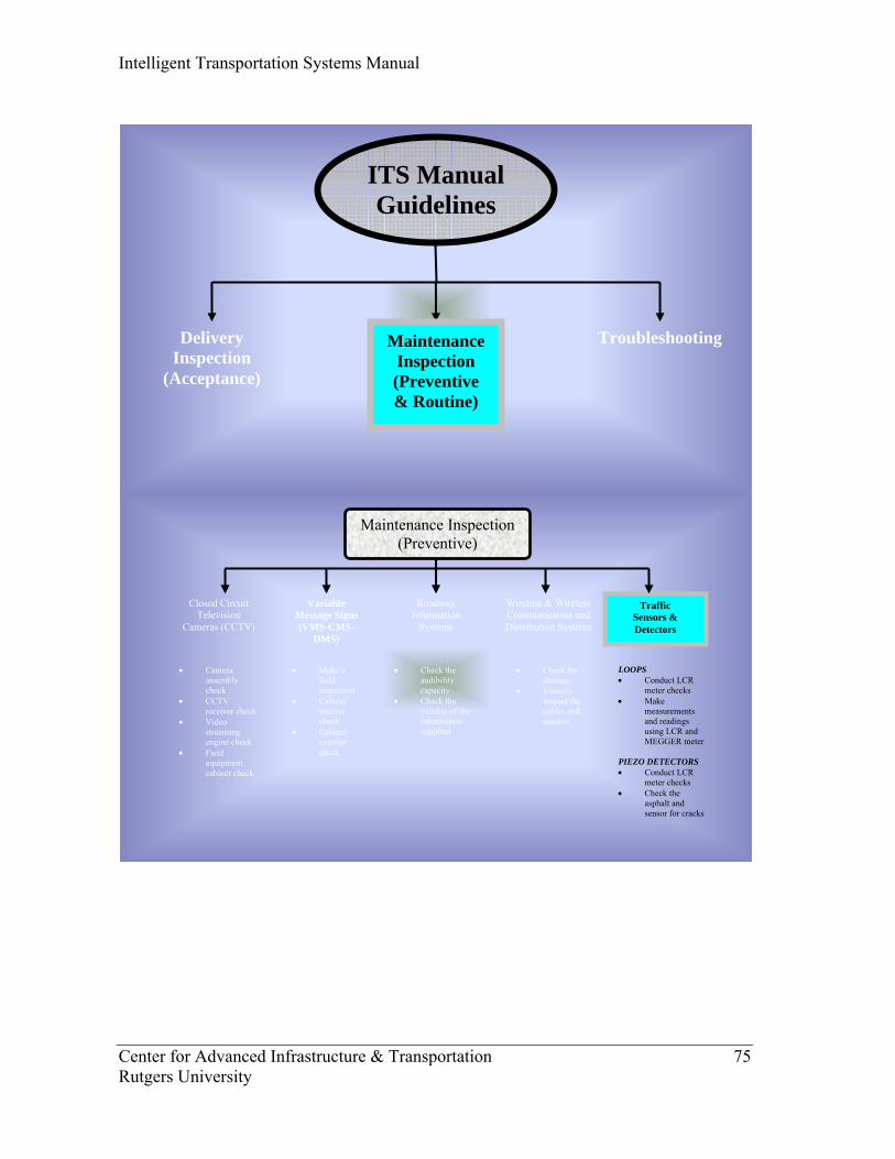
Intelligent Transportation Systems Manual
Center for Advanced Infrastructure & Transportation 75 Rutgers University
Closed Circuit Television
Cameras (CCTV)
Maintenance Inspection (Preventive)
Variable Message Signs (VMS-CMS-
DMS)
Traffic Sensors & Detectors
Roadway Information
Systems
• Camera assembly check
• CCTV receiver check
• Video streaming engine check
• Field equipment cabinet check
• Make a field inspection
• Cabinet interior check
• Cabinet exterior check
• Check the audibility capacity
• Check the validity of the information supplied
LOOPS • Conduct LCR
meter checks • Make
measurements and readings using LCR and MEGGER meter
PIEZO DETECTORS • Conduct LCR
meter checks • Check the
asphalt and sensor for cracks
Wireline & Wireless Communication and Distribution Systems
• Check for damage.
• Visually inspect the cables and conduit.
ITS Manual Guidelines
Delivery Inspection
(Acceptance)
Troubleshooting Maintenance Inspection (Preventive & Routine)
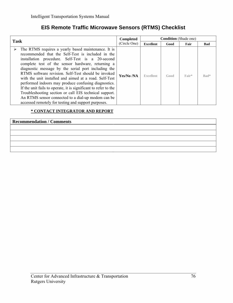
Intelligent Transportation Systems Manual
Center for Advanced Infrastructure & Transportation 76 Rutgers University
EIS Remote Traffic Microwave Sensors (RTMS) Checklist
Condition (Shade one) Task Completed (Circle One) Excellent Good Fair Bad
The RTMS requires a yearly based maintenance. It is recommended that the Self-Test is included in the installation procedure. Self-Test is a 20-second complete test of the sensor hardware, returning a diagnostic message by the serial port including the RTMS software revision. Self-Test should be invoked with the unit installed and aimed at a road. Self-Test performed indoors may produce confusing diagnostics. If the unit fails to operate, it is significant to refer to the Troubleshooting section or call EIS technical support. An RTMS sensor connected to a dial-up modem can be accessed remotely for testing and support purposes.
Yes/No /NA Excellent Good Fair* Bad*
* CONTACT INTEGRATOR AND REPORT
Recommendation / Comments
Intelligent Transportation Systems Manual
Center for Advanced Infrastructure & Transportation 77 Rutgers University
“Draft”
INTELLIGENT
TRANSPORTATION SYSTEMS
(ITS) MANUAL
PREVENTIVE/ROUTINE
MAINTENANCE
CHECKLISTS
FOR SPECIFIC COMPONENTS Prepared by
Center for Advanced Infrastructure & Transportation (CAIT)
Rutgers University
June 2007
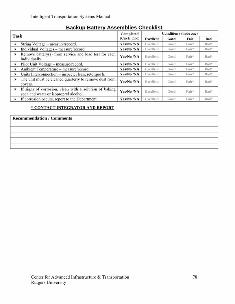
Intelligent Transportation Systems Manual
Center for Advanced Infrastructure & Transportation 78 Rutgers University
Backup Battery Assemblies Checklist Condition (Shade one) Task Completed
(Circle One) Excellent Good Fair Bad String Voltage – measure/record. Yes/No /NA Excellent Good Fair* Bad* Individual Voltages – measure/record. Yes/No /NA Excellent Good Fair* Bad* Remove battery(s) from service and load test for each
individually. Yes/No /NA Excellent Good Fair* Bad*
Pilot Unit Voltage – measure/record. Yes/No /NA Excellent Good Fair* Bad* Ambient Temperature – measure/record. Yes/No /NA Excellent Good Fair* Bad* Units Interconnection – inspect, clean, retorque h. Yes/No /NA Excellent Good Fair* Bad* The unit must be cleaned quarterly to remove dust from
covers. Yes/No /NA Excellent Good Fair* Bad*
If signs of corrosion, clean with a solution of baking soda and water or isopropryl alcohol. Yes/No /NA Excellent Good Fair* Bad*
If corrosion occurs, report to the Department. Yes/No /NA Excellent Good Fair* Bad* * CONTACT INTEGRATOR AND REPORT
Recommendation / Comments
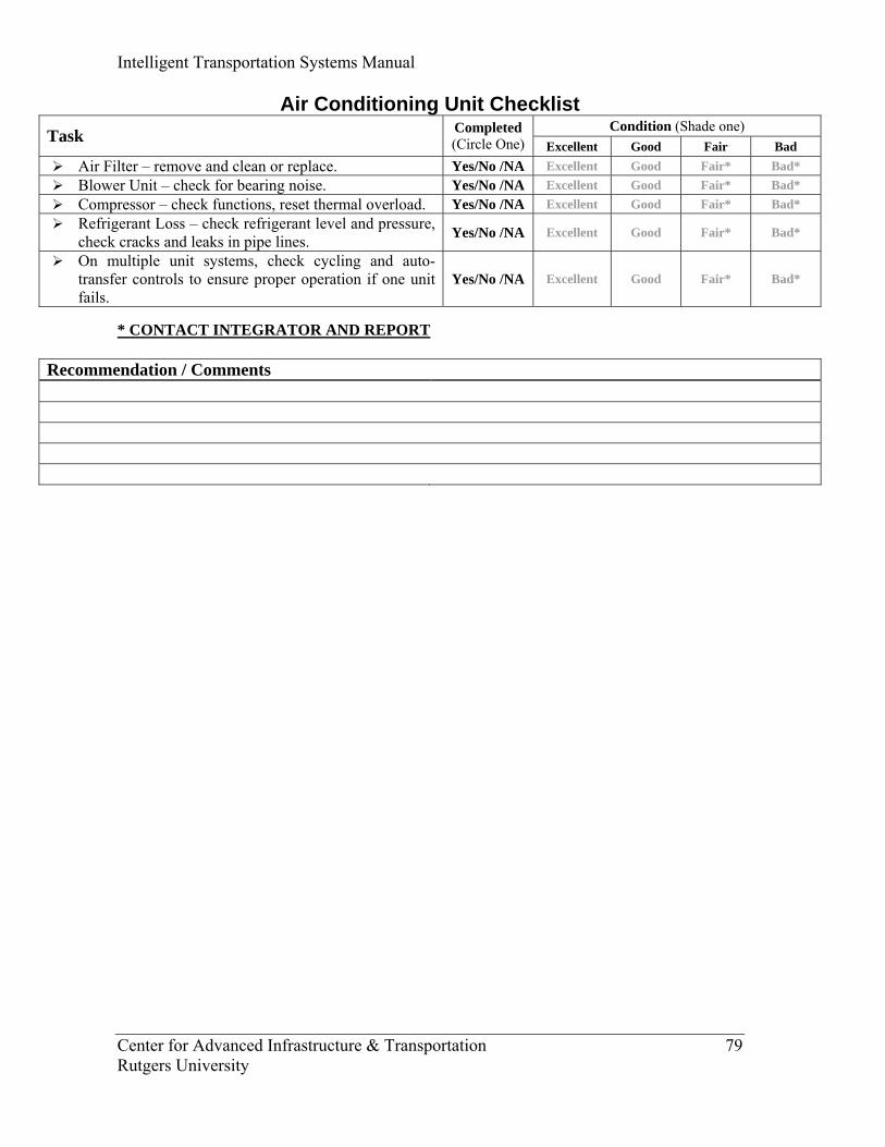
Intelligent Transportation Systems Manual
Center for Advanced Infrastructure & Transportation 79 Rutgers University
Air Conditioning Unit Checklist Condition (Shade one) Task Completed
(Circle One) Excellent Good Fair Bad Air Filter – remove and clean or replace. Yes/No /NA Excellent Good Fair* Bad* Blower Unit – check for bearing noise. Yes/No /NA Excellent Good Fair* Bad* Compressor – check functions, reset thermal overload. Yes/No /NA Excellent Good Fair* Bad* Refrigerant Loss – check refrigerant level and pressure,
check cracks and leaks in pipe lines. Yes/No /NA Excellent Good Fair* Bad*
On multiple unit systems, check cycling and auto-transfer controls to ensure proper operation if one unit fails.
Yes/No /NA Excellent Good Fair* Bad*
* CONTACT INTEGRATOR AND REPORT
Recommendation / Comments

Intelligent Transportation Systems Manual
Center for Advanced Infrastructure & Transportation 80 Rutgers University
Generator Checklist Condition (Shade one) Task Completed
(Circle One) Excellent Good Fair Bad Check oil and change if necessary. Replace oil filter if
necessary. Yes/No /NA Excellent Good Fair* Bad*
Clean air filter and replace if necessary. Yes/No /NA Excellent Good Fair* Bad* Check and clean sediment bowl. Yes/No /NA Excellent Good Fair* Bad* Check for gas leaks. Yes/No /NA Excellent Good Fair* Bad* Inspect battery terminals and fluid. Yes/No /NA Excellent Good Fair* Bad* Check hydraulic fluid, brake fluid, lube jacks and sign
pole (for portable VMS only). Yes/No /NA Excellent Good Fair* Bad*
Clean cooling fins. Yes/No /NA Excellent Good Fair* Bad* Set rocker arm clearance (for mechanic). Yes/No /NA Excellent Good Fair* Bad* Set and clean injectors (for mechanic). Yes/No /NA Excellent Good Fair* Bad* Start the generator and take a power reading. Yes/No /NA Excellent Good Fair* Bad*
* CONTACT INTEGRATOR AND REPORT
Recommendation / Comments
Intelligent Transportation Systems Manual
Center for Advanced Infrastructure & Transportation 81 Rutgers University
“Draft”
INTELLIGENT
TRANSPORTATION SYSTEMS
(ITS) MANUAL
GENERIC
TROUBLESHOOTING GUIDE
Prepared by
Center for Advanced Infrastructure & Transportation (CAIT)
Rutgers University
June 2007
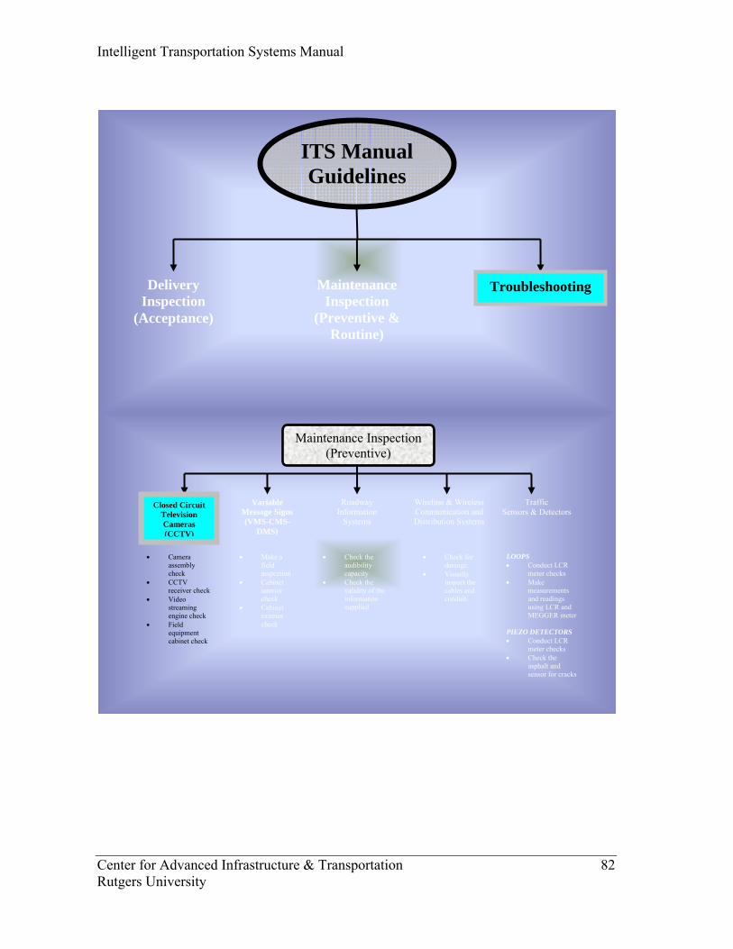
Intelligent Transportation Systems Manual
Center for Advanced Infrastructure & Transportation 82 Rutgers University
Closed Circuit Television Cameras (CCTV)
Maintenance Inspection (Preventive)
Variable Message Signs (VMS-CMS-
DMS)
Traffic Sensors & Detectors
Roadway Information
Systems
• Camera assembly check
• CCTV receiver check
• Video streaming engine check
• Field equipment cabinet check
• Make a field inspection
• Cabinet interior check
• Cabinet exterior check
• Check the audibility capacity
• Check the validity of the information supplied
LOOPS • Conduct LCR
meter checks • Make
measurements and readings using LCR and MEGGER meter
PIEZO DETECTORS • Conduct LCR
meter checks • Check the
asphalt and sensor for cracks
Wireline & Wireless Communication and Distribution Systems
• Check for damage.
• Visually inspect the cables and conduit.
ITS Manual Guidelines
Delivery Inspection
(Acceptance)
TroubleshootingMaintenance Inspection
(Preventive & Routine)
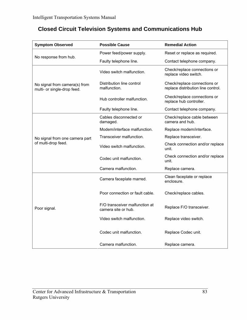
Intelligent Transportation Systems Manual
Center for Advanced Infrastructure & Transportation 83 Rutgers University
Closed Circuit Television Systems and Communications Hub
Symptom Observed Possible Cause Remedial Action
Power feed/power supply. Reset or replace as required. No response from hub.
Faulty telephone line. Contact telephone company.
Video switch malfunction. Check/replace connections or replace video switch.
Distribution line control malfunction.
Check/replace connections or replace distribution line control.
Hub controller malfunction. Check/replace connections or replace hub controller.
No signal from camera(s) from multi- or single-drop feed.
Faulty telephone line. Contact telephone company.
Cables disconnected or damaged.
Check/replace cable between camera and hub.
Modem/interface malfunction. Replace modem/interface.
Transceiver malfunction. Replace transceiver.
Video switch malfunction. Check connection and/or replace unit.
Codec unit malfunction. Check connection and/or replace unit.
No signal from one camera part of multi-drop feed.
Camera malfunction. Replace camera.
Camera faceplate marred. Clean faceplate or replace enclosure.
Poor connection or fault cable. Check/replace cables.
F/O transceiver malfunction at camera site or hub. Replace F/O transceiver.
Video switch malfunction. Replace video switch.
Codec unit malfunction. Replace Codec unit.
Poor signal.
Camera malfunction. Replace camera.

Intelligent Transportation Systems Manual
Center for Advanced Infrastructure & Transportation 84 Rutgers University
Symptom Observed Possible Cause Remedial Action
Poor cable connection. Check/replace cable.
CCR/MPC malfunction. Replace CCR/MPC.
Distribution line control malfunction. Replace distribution line control.
Pan/tilt not responding.
Hub controller malfunction. Replace hub controller.
Lens malfunction. Replace lens.
CCR/MPC malfunction. Replace CCR/MPC.
Damaged cable between camera and controller. Replace cable.
Hub controller malfunction. Replace hub controller.
Out of focus or no zoom.
Distribution line control malfunction. Replace distribution line control.
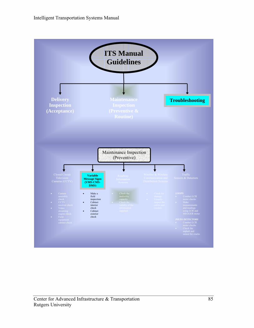
Intelligent Transportation Systems Manual
Center for Advanced Infrastructure & Transportation 85 Rutgers University
Closed Circuit Television
Cameras (CCTV)
Maintenance Inspection (Preventive)
Variable Message Signs (VMS-CMS-
DMS)
Traffic Sensors & Detectors
• Camera assembly check
• CCTV receiver check
• Video streaming engine check
• Field equipment cabinet check
• Make a field inspection
• Cabinet interior check
• Cabinet exterior check
• Check the audibility capacity
• Check the validity of the information supplied
LOOPS • Conduct LCR
meter checks • Make
measurements and readings using LCR and MEGGER meter
PIEZO DETECTORS • Conduct LCR
meter checks • Check the
asphalt and sensor for cracks
Wireline & Wireless Communication and Distribution Systems
• Check for damage.
• Visually inspect the cables and conduit.
Roadway Information
Systems
ITS Manual Guidelines
Delivery Inspection
(Acceptance)
TroubleshootingMaintenance Inspection
(Preventive & Routine)
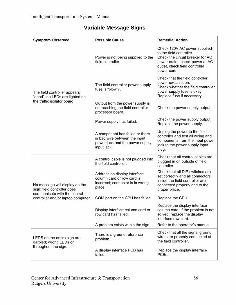
Intelligent Transportation Systems Manual
Center for Advanced Infrastructure & Transportation 86 Rutgers University
Variable Message Signs
Symptom Observed Possible Cause Remedial Action
Power is not being supplied to the field controller.
Check 120V AC power supplied to the field controller. Check the circuit breaker for AC power outlet, check power at AC outlet, check field controller power cord.
The field controller power supply fuse is “blown”.
Check that the field controller power switch is on. Check whether the field controller power supply fuse is okay. Replace fuse if necessary.
Output from the power supply is not reaching the field controller processor board.
Check the power supply output.
Power supply has failed. Check the power supply output. Replace the power supply.
The field controller appears “dead”, no LEDs are lighted on the traffic isolator board.
A component has failed or there is bad wire between the input power jack and the power supply input jack.
Unplug the power to the field controller and test all wiring and components from the input power jack to the power supply input plug.
A control cable is not plugged into the field controller.
Check that all control cables are plugged in on outside of field controller.
Address on display interface column card or row card is incorrect; connector is in wrong place.
Check that all DIP switches are set correctly and all connectors inside the field controller are connected properly and to the proper place.
COM port on the CPU has failed. Replace the CPU.
Display interface column card or row card has failed.
Replace the display interface column card. If the problem is not solved, replace the display interface row card.
No message will display on the sign; field controller does communicate with the central controller and/or laptop computer.
A problem exists within the sign. Refer to the operator’s manual.
There is a ground reference problem.
Check that all the signal ground wires are properly connected at the field controller.
LEDS on the entire sign are garbled; wrong LEDs on throughout the sign. A display interface PCB has
failed. Replace the display interface PCBs.
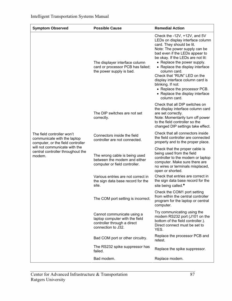
Intelligent Transportation Systems Manual
Center for Advanced Infrastructure & Transportation 87 Rutgers University
Symptom Observed Possible Cause Remedial Action
The displayer interface column card or processor PCB has failed; the power supply is bad.
Check the -12V, +12V, and 5V LEDs on display interface column card. They should be lit. Note: The power supply can be bad even if the LEDs appear to be okay. If the LEDs are not lit: • Replace the power supply. • Replace the display interface
column card. Check that “RUN” LED on the display interface column card is blinking. If not: • Replace the processor PCB. • Replace the display interface
column card.
The DIP switches are not set correctly.
Check that all DIP switches on the display interface column card are set correctly. Note: Momentarily turn off power to the field controller so the changed DIP settings take effect.
Connectors inside the field controller are not connected.
Check that all connectors inside the field controller are connected properly and to the proper place.
The wrong cable is being used between the modem and either computer or field controller.
Check that the proper cable is being used from the field controller to the modem or laptop computer. Make sure there are no wires or terminals misplaced, open or shorted.
Various entries are not correct in the sign data base record for the site.
Check that entries are correct in the sign data base record for the site being called.*
The COM port setting is incorrect.
Check the COM1 port setting from within the central controller program for the laptop or central computer.
Cannot communicate using a laptop computer with the field controller through a direct connection to J32.
Try communicating using the modem RS232 port (J101 on the bottom of the field controller.). Direct connect must be set to YES.
Bad COM port or other circuitry. Replace the processor PCB and retest.
The RS232 spike suppressor has failed. Replace the spike suppressor.
The field controller won’t communicate with the laptop computer, or the field controller will not communicate with the central controller throughout the modem.
Bad modem. Replace modem.
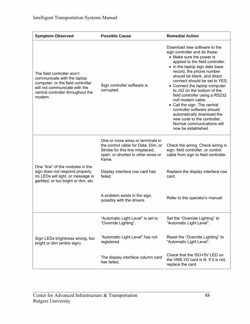
Intelligent Transportation Systems Manual
Center for Advanced Infrastructure & Transportation 88 Rutgers University
Symptom Observed Possible Cause Remedial Action
The field controller won’t communicate with the laptop computer, or the field controller will not communicate with the central controller throughout the modem.
Sign controller software is corrupted.
Download new software to the sign controller and do these: • Make sure the power is
applied to the field controller. • In the laptop sign data base
record, the phone number should be blank, and direct connect should be set to YES.
• Connect the laptop computer to J32 on the bottom of the field controller using a RS232 null modem cable.
• Call the sign. The central controller software should automatically download the new code to the controller. Normal communications will now be established.
One or more wires or terminals in the control cable for Data, Dim, or Strobe for this line misplaced, open, or shorted to other wires or frame.
Check the wiring. Check wiring in sign, field controller, or control cable from sign to field controller.
Display interface row card has failed.
Replace the display interface row card.
One “line” of the modules in the sign does not respond properly, no LEDs will light, or message is garbled, or too bright or dim, etc.
A problem exists in the sign, possibly with the drivers. Refer to the operator’s manual.
“Automatic Light Level” is set to “Override Lighting”.
Set the “Override Lighting” to “Automatic Light Level”.
“Automatic Light Level” has not registered.
Reset the “Override Lighting” to “Automatic Light Level”.
Sign LEDs brightness wrong, too bright or dim (entire sign).
The display interface column card has failed.
Check that the ISO+5V LED on the VMS I/O card is lit. If it is not, replace the card.
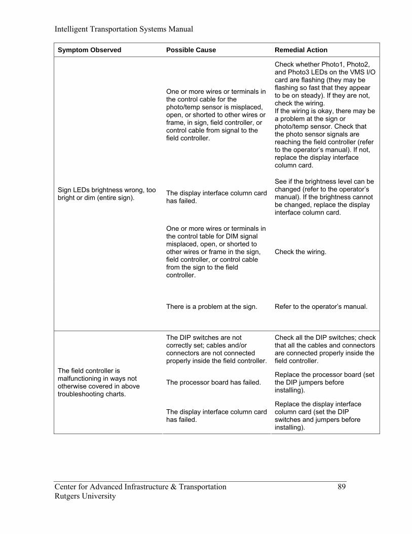
Intelligent Transportation Systems Manual
Center for Advanced Infrastructure & Transportation 89 Rutgers University
Symptom Observed Possible Cause Remedial Action
One or more wires or terminals in the control cable for the photo/temp sensor is misplaced, open, or shorted to other wires or frame, in sign, field controller, or control cable from signal to the field controller.
Check whether Photo1, Photo2, and Photo3 LEDs on the VMS I/O card are flashing (they may be flashing so fast that they appear to be on steady). If they are not, check the wiring. If the wiring is okay, there may be a problem at the sign or photo/temp sensor. Check that the photo sensor signals are reaching the field controller (refer to the operator’s manual). If not, replace the display interface column card.
The display interface column card has failed.
See if the brightness level can be changed (refer to the operator’s manual). If the brightness cannot be changed, replace the display interface column card.
One or more wires or terminals in the control table for DIM signal misplaced, open, or shorted to other wires or frame in the sign, field controller, or control cable from the sign to the field controller.
Check the wiring.
Sign LEDs brightness wrong, too bright or dim (entire sign).
There is a problem at the sign. Refer to the operator’s manual.
The DIP switches are not correctly set; cables and/or connectors are not connected properly inside the field controller.
Check all the DIP switches; check that all the cables and connectors are connected properly inside the field controller.
The processor board has failed. Replace the processor board (set the DIP jumpers before installing).
The field controller is malfunctioning in ways not otherwise covered in above troubleshooting charts.
The display interface column card has failed.
Replace the display interface column card (set the DIP switches and jumpers before installing).
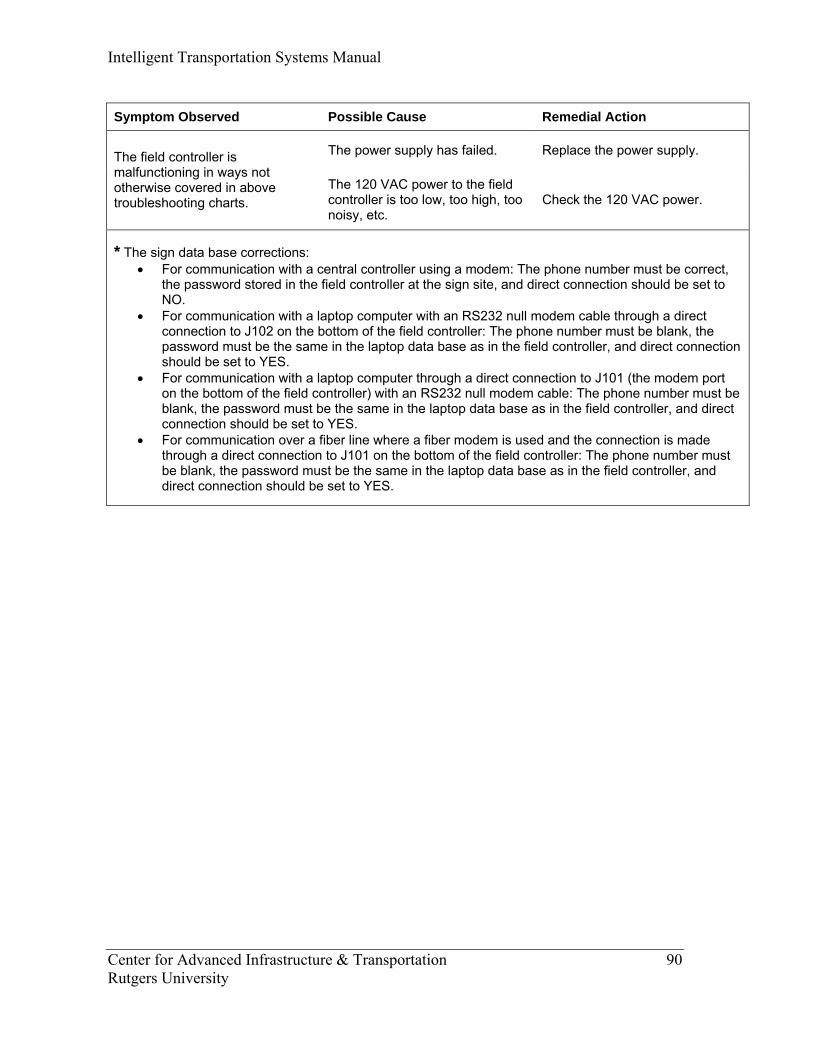
Intelligent Transportation Systems Manual
Center for Advanced Infrastructure & Transportation 90 Rutgers University
Symptom Observed Possible Cause Remedial Action
The power supply has failed. Replace the power supply. The field controller is malfunctioning in ways not otherwise covered in above troubleshooting charts.
The 120 VAC power to the field controller is too low, too high, too noisy, etc.
Check the 120 VAC power.
* The sign data base corrections: • For communication with a central controller using a modem: The phone number must be correct,
the password stored in the field controller at the sign site, and direct connection should be set to NO.
• For communication with a laptop computer with an RS232 null modem cable through a direct connection to J102 on the bottom of the field controller: The phone number must be blank, the password must be the same in the laptop data base as in the field controller, and direct connection should be set to YES.
• For communication with a laptop computer through a direct connection to J101 (the modem port on the bottom of the field controller) with an RS232 null modem cable: The phone number must be blank, the password must be the same in the laptop data base as in the field controller, and direct connection should be set to YES.
• For communication over a fiber line where a fiber modem is used and the connection is made through a direct connection to J101 on the bottom of the field controller: The phone number must be blank, the password must be the same in the laptop data base as in the field controller, and direct connection should be set to YES.
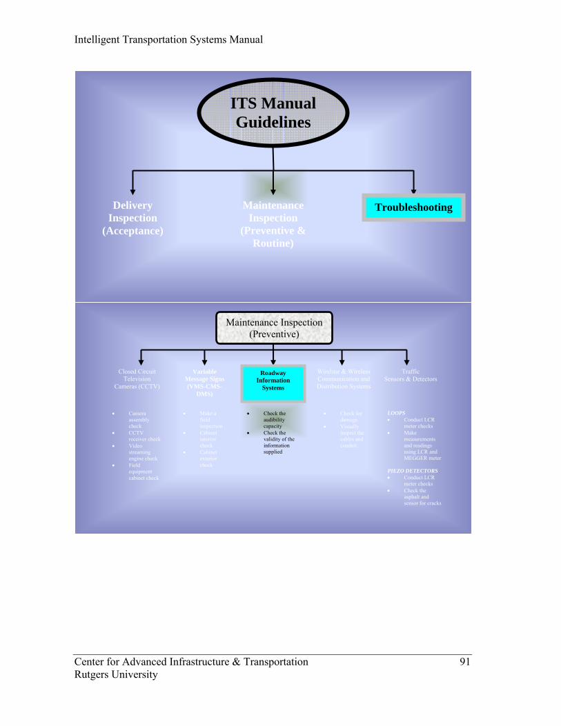
Intelligent Transportation Systems Manual
Center for Advanced Infrastructure & Transportation 91 Rutgers University
Closed Circuit Television
Cameras (CCTV)
Maintenance Inspection (Preventive)
Variable Message Signs (VMS-CMS-
DMS)
Traffic Sensors & Detectors
Roadway Information
Systems
• Camera assembly check
• CCTV receiver check
• Video streaming engine check
• Field equipment cabinet check
• Make a field inspection
• Cabinet interior check
• Cabinet exterior check
• Check the audibility capacity
• Check the validity of the information supplied
LOOPS • Conduct LCR
meter checks • Make
measurements and readings using LCR and MEGGER meter
PIEZO DETECTORS • Conduct LCR
meter checks • Check the
asphalt and sensor for cracks
Wireline & Wireless Communication and Distribution Systems
• Check for damage.
• Visually inspect the cables and conduit.
ITS Manual Guidelines
Delivery Inspection
(Acceptance)
TroubleshootingMaintenance Inspection
(Preventive & Routine)
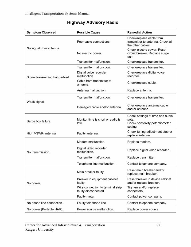
Intelligent Transportation Systems Manual
Center for Advanced Infrastructure & Transportation 92 Rutgers University
Highway Advisory Radio Symptom Observed Possible Cause Remedial Action
Poor cable connections. Check/replace cable from transmitter to antenna. Check all the other cables.
No electric power. Check electric power. Reset circuit breaker. Replace surge unit.
No signal from antenna.
Transmitter malfunction. Check/replace transmitter.
Transmitter malfunction. Check/replace transmitter. Digital voice recorder malfunction.
Check/replace digital voice recorder.
Cable from transmitter to antenna. Check/replace cable.
Signal transmitting but garbled.
Antenna malfunction. Replace antenna.
Transmitter malfunction. Check/replace transmitter. Weak signal. Damaged cable and/or antenna. Check/replace antenna cable
and/or antenna.
Barge box failure. Monitor time is short or audio is low.
Check settings of time and audio pots. Check sensitivity potentiometer setting.
High VSWR-antenna. Faulty antenna. Check tuning adjustment stub or replace antenna.
Modem malfunction. Replace modem.
Digital video recorder malfunction. Replace digital video recorder.
Transmitter malfunction. Replace transmitter. No transmission.
Telephone line malfunction. Contact telephone company.
Main breaker faulty. Reset main breaker and/or replace main breaker.
Breaker in equipment cabinet faulty.
Reset breaker in device cabinet and/or replace breaker.
Wire connection to terminal strip faulty disconnected.
Tighten and/or replace connectors.
No power.
Faulty meter. Contact power company.
No phone line connection. Faulty telephone line. Contact telephone company.
No power (Portable HAR). Power source malfunction. Replace power source.
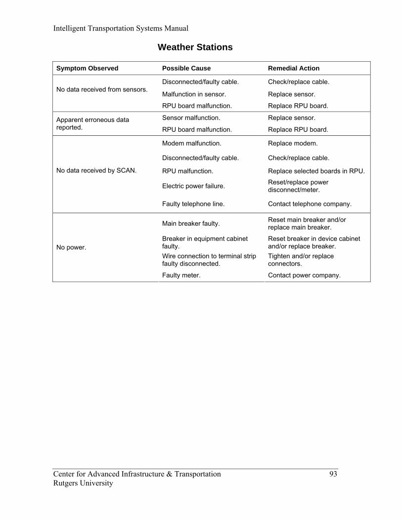
Intelligent Transportation Systems Manual
Center for Advanced Infrastructure & Transportation 93 Rutgers University
Weather Stations Symptom Observed Possible Cause Remedial Action
Disconnected/faulty cable. Check/replace cable.
Malfunction in sensor. Replace sensor. No data received from sensors.
RPU board malfunction. Replace RPU board.
Sensor malfunction. Replace sensor. Apparent erroneous data reported. RPU board malfunction. Replace RPU board.
Modem malfunction. Replace modem.
Disconnected/faulty cable. Check/replace cable.
RPU malfunction. Replace selected boards in RPU.
Electric power failure. Reset/replace power disconnect/meter.
No data received by SCAN.
Faulty telephone line. Contact telephone company.
Main breaker faulty. Reset main breaker and/or replace main breaker.
Breaker in equipment cabinet faulty.
Reset breaker in device cabinet and/or replace breaker.
Wire connection to terminal strip faulty disconnected.
Tighten and/or replace connectors.
No power.
Faulty meter. Contact power company.

Intelligent Transportation Systems Manual
Center for Advanced Infrastructure & Transportation 94 Rutgers University
Closed Circuit Television
Cameras (CCTV)
Maintenance Inspection (Preventive)
Variable Message Signs (VMS-CMS-
DMS)
Traffic Sensors & Detectors
Roadway Information
Systems
• Camera assembly check
• CCTV receiver check
• Video streaming engine check
• Field equipment cabinet check
• Make a field inspection
• Cabinet interior check
• Cabinet exterior check
• Check the audibility capacity
• Check the validity of the information supplied
LOOPS • Conduct LCR
meter checks • Make
measurements and readings using LCR and MEGGER meter
PIEZO DETECTORS • Conduct LCR
meter checks • Check the
asphalt and sensor for cracks
Wireline & Wireless Communication and Distribution Systems
• Check for damage.
• Visually inspect the cables and conduit.
ITS Manual Guidelines
Delivery Inspection
(Acceptance)
TroubleshootingMaintenance Inspection
(Preventive & Routine)

Intelligent Transportation Systems Manual
Center for Advanced Infrastructure & Transportation 95 Rutgers University
Out Pavement Detectors
Symptom Observed Possible Cause Remedial Action
PC board. Replace detector unit. Detector malfunction. Radar assembly. Replace multiplexer unit.
Power supply. Multiplexer malfunction. PC board.
Replace multiplexer unit.
Prom module not installed.
Power supply or CPU not operative.
Controller power on, all display segments are lit and read zero.
I/O inoperative.
Replace controller unit.
Controller operational, one or more outputs on continuously. Output shorted. Replace controller unit.
Keyboard and display module defective.
Input module defective. Controller not responding to keyboard.
Defective cable to front panel.
Replace controller unit.
LED display defective.
Defective decoder chip on module.
Segment missing on display.
Output module defective.
Replace controller unit.
Incorrect segment display indications. Defective module. Replace controller unit.
Defective CPU module. Keyboard response wrong or erratic. Defective I/O module.
Replace controller unit.
No data transmission. I/O error. Contact telephone company.
No data transmission input/output. Modem failed. Replace modem unit.
Main breaker faulty. Reset main breaker and/or replace main breaker.
Breaker in equipment cabinet faulty.
Reset breaker in device cabinet and/or replace breaker.
Wire connection to terminal strip faulty disconnected.
Tighten and/or replace connectors.
No power.
Faulty meter. Contact power company.

Intelligent Transportation Systems Manual
Center for Advanced Infrastructure & Transportation 96 Rutgers University
Symptom Observed Possible Cause Remedial Action
Damaged cable or antenna. Check/replace cable and/or antenna.
Transceiver malfunction. Check connections/replace transceiver
Signal not receiving (Locations with Spread Spectrum Radio).
No electric power. Check electric power.
Intelligent Transportation Systems Manual
Center for Advanced Infrastructure & Transportation 97 Rutgers University
“Draft”
INTELLIGENT
TRANSPORTATION SYSTEMS
(ITS) MANUAL
BRAND SPECIFIC
TROUBLESHOOTING GUIDE
Prepared by
Center for Advanced Infrastructure & Transportation (CAIT)
Rutgers University
June 2007

Intelligent Transportation Systems Manual
Center for Advanced Infrastructure & Transportation 98 Rutgers University
Closed Circuit Television Cameras (CCTV)
Maintenance Inspection (Preventive)
Variable Message Signs (VMS-CMS-
DMS)
Traffic Sensors & Detectors
Roadway Information
Systems
• Camera assembly check
• CCTV receiver check
• Video streaming engine check
• Field equipment cabinet check
• Make a field inspection
• Cabinet interior check
• Cabinet exterior check
• Check the audibility capacity
• Check the validity of the information supplied
LOOPS • Conduct LCR
meter checks • Make
measurements and readings using LCR and MEGGER meter
PIEZO DETECTORS • Conduct LCR
meter checks • Check the
asphalt and sensor for cracks
Wireline & Wireless Communication and Distribution Systems
• Check for damage.
• Visually inspect the cables and conduit.
ITS Manual Guidelines
Delivery Inspection
(Acceptance)
TroubleshootingMaintenance Inspection
(Preventive & Routine)
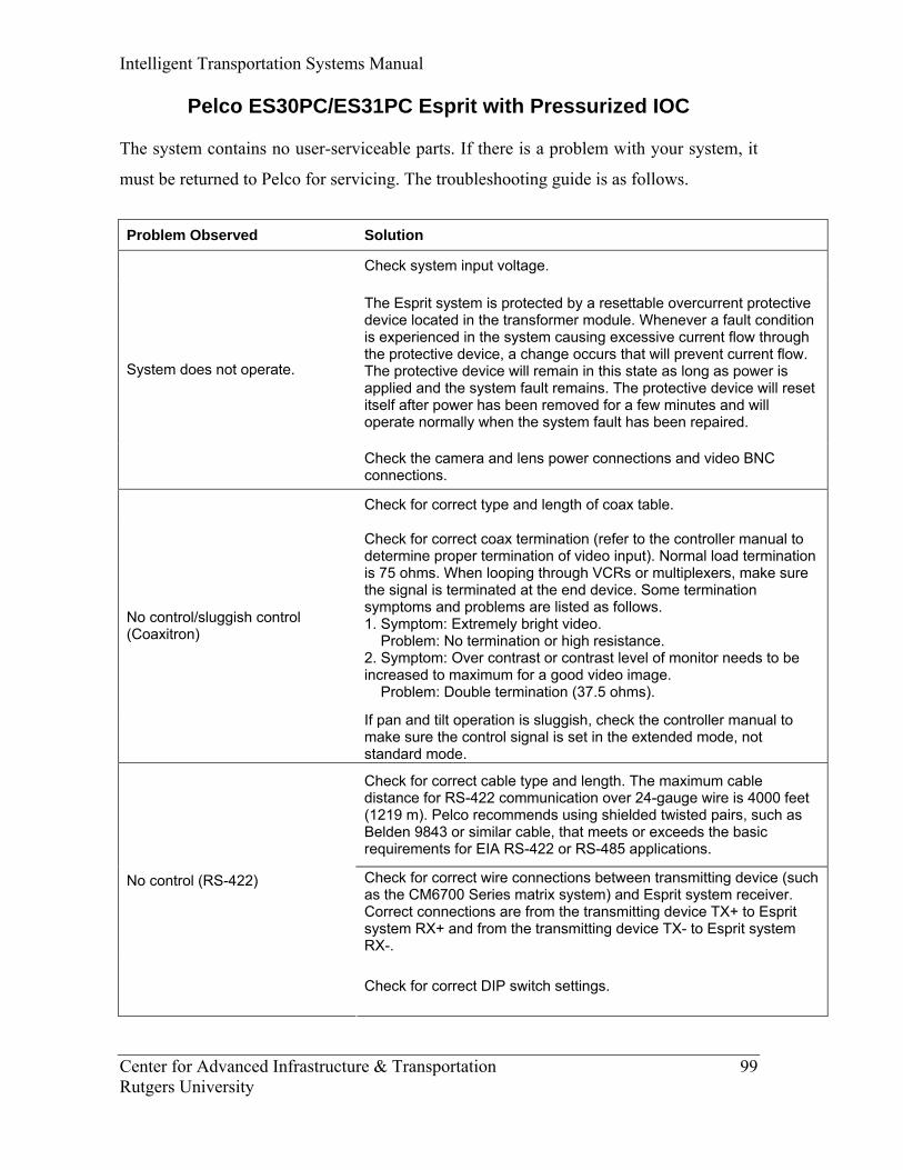
Intelligent Transportation Systems Manual
Center for Advanced Infrastructure & Transportation 99 Rutgers University
Pelco ES30PC/ES31PC Esprit with Pressurized IOC
The system contains no user-serviceable parts. If there is a problem with your system, it
must be returned to Pelco for servicing. The troubleshooting guide is as follows.
Problem Observed Solution
Check system input voltage.
The Esprit system is protected by a resettable overcurrent protective device located in the transformer module. Whenever a fault condition is experienced in the system causing excessive current flow through the protective device, a change occurs that will prevent current flow. The protective device will remain in this state as long as power is applied and the system fault remains. The protective device will reset itself after power has been removed for a few minutes and will operate normally when the system fault has been repaired.
System does not operate.
Check the camera and lens power connections and video BNC connections.
Check for correct type and length of coax table.
Check for correct coax termination (refer to the controller manual to determine proper termination of video input). Normal load termination is 75 ohms. When looping through VCRs or multiplexers, make sure the signal is terminated at the end device. Some termination symptoms and problems are listed as follows. 1. Symptom: Extremely bright video. Problem: No termination or high resistance. 2. Symptom: Over contrast or contrast level of monitor needs to be increased to maximum for a good video image. Problem: Double termination (37.5 ohms).
No control/sluggish control (Coaxitron)
If pan and tilt operation is sluggish, check the controller manual to make sure the control signal is set in the extended mode, not standard mode.
Check for correct cable type and length. The maximum cable distance for RS-422 communication over 24-gauge wire is 4000 feet (1219 m). Pelco recommends using shielded twisted pairs, such as Belden 9843 or similar cable, that meets or exceeds the basic requirements for EIA RS-422 or RS-485 applications.
Check for correct wire connections between transmitting device (such as the CM6700 Series matrix system) and Esprit system receiver. Correct connections are from the transmitting device TX+ to Esprit system RX+ and from the transmitting device TX- to Esprit system RX-.
No control (RS-422)
Check for correct DIP switch settings.
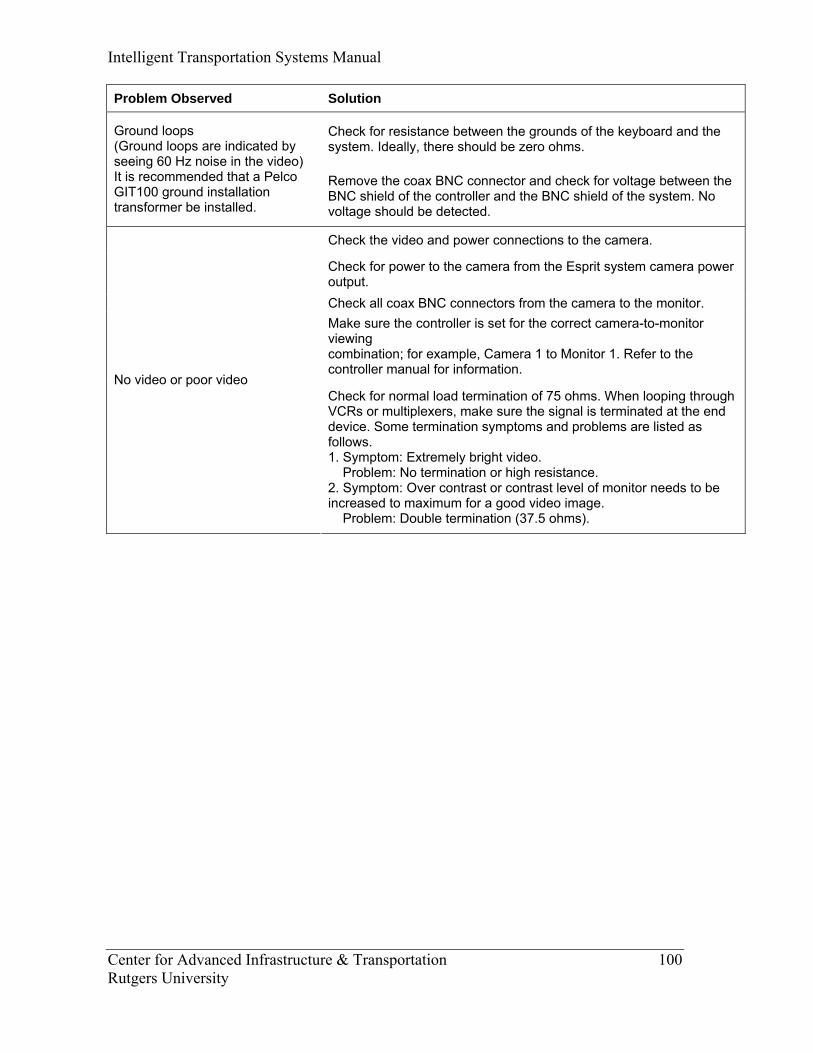
Intelligent Transportation Systems Manual
Center for Advanced Infrastructure & Transportation 100 Rutgers University
Problem Observed Solution
Check for resistance between the grounds of the keyboard and the system. Ideally, there should be zero ohms.
Ground loops (Ground loops are indicated by seeing 60 Hz noise in the video) It is recommended that a Pelco GIT100 ground installation transformer be installed.
Remove the coax BNC connector and check for voltage between the BNC shield of the controller and the BNC shield of the system. No voltage should be detected.
Check the video and power connections to the camera.
Check for power to the camera from the Esprit system camera power output. Check all coax BNC connectors from the camera to the monitor. Make sure the controller is set for the correct camera-to-monitor viewing combination; for example, Camera 1 to Monitor 1. Refer to the controller manual for information.
No video or poor video Check for normal load termination of 75 ohms. When looping through VCRs or multiplexers, make sure the signal is terminated at the end device. Some termination symptoms and problems are listed as follows. 1. Symptom: Extremely bright video. Problem: No termination or high resistance. 2. Symptom: Over contrast or contrast level of monitor needs to be increased to maximum for a good video image. Problem: Double termination (37.5 ohms).

Intelligent Transportation Systems Manual
Center for Advanced Infrastructure & Transportation 101 Rutgers University
Closed Circuit Television
Cameras (CCTV)
Maintenance Inspection (Preventive)
Variable Message Signs (VMS-CMS-
DMS)
Traffic Sensors & Detectors
• Camera assembly check
• CCTV receiver check
• Video streaming engine check
• Field equipment cabinet check
• Make a field inspection
• Cabinet interior check
• Cabinet exterior check
• Check the audibility capacity
• Check the validity of the information supplied
LOOPS • Conduct LCR
meter checks • Make
measurements and readings using LCR and MEGGER meter
PIEZO DETECTORS • Conduct LCR
meter checks • Check the
asphalt and sensor for cracks
Wireline & Wireless Communication and Distribution Systems
• Check for damage.
• Visually inspect the cables and conduit.
Roadway Information
Systems
ITS Manual Guidelines
Delivery Inspection
(Acceptance)
TroubleshootingMaintenance Inspection
(Preventive & Routine)
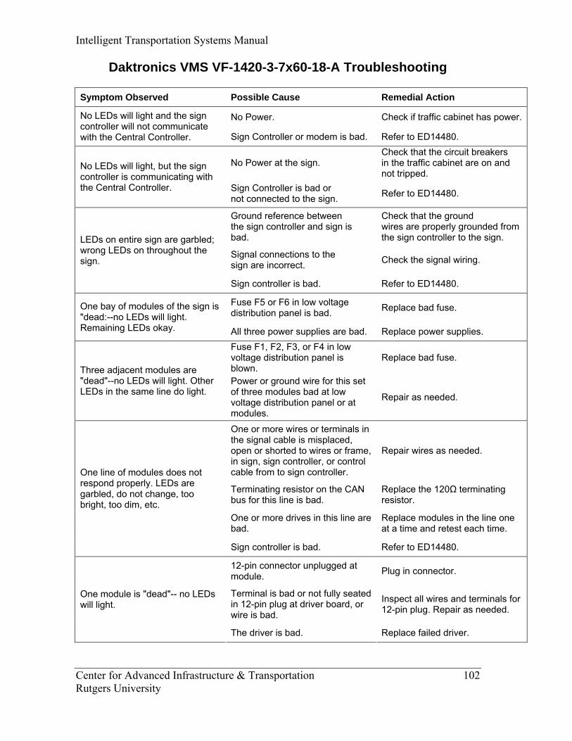
Intelligent Transportation Systems Manual
Center for Advanced Infrastructure & Transportation 102 Rutgers University
Daktronics VMS VF-1420-3-7x60-18-A Troubleshooting
Symptom Observed Possible Cause Remedial Action
No Power. Check if traffic cabinet has power.No LEDs will light and the sign controller will not communicate with the Central Controller. Sign Controller or modem is bad. Refer to ED14480.
No Power at the sign. Check that the circuit breakers in the traffic cabinet are on and not tripped.
No LEDs will light, but the sign controller is communicating with the Central Controller. Sign Controller is bad or
not connected to the sign. Refer to ED14480.
Ground reference between the sign controller and sign is bad.
Check that the ground wires are properly grounded from the sign controller to the sign.
Signal connections to the sign are incorrect. Check the signal wiring.
LEDs on entire sign are garbled; wrong LEDs on throughout the sign.
Sign controller is bad. Refer to ED14480.
Fuse F5 or F6 in low voltage distribution panel is bad. Replace bad fuse. One bay of modules of the sign is
"dead:--no LEDs will light. Remaining LEDs okay. All three power supplies are bad. Replace power supplies.
Fuse F1, F2, F3, or F4 in low voltage distribution panel is blown.
Replace bad fuse. Three adjacent modules are "dead"--no LEDs will light. Other LEDs in the same line do light.
Power or ground wire for this set of three modules bad at low voltage distribution panel or at modules.
Repair as needed.
One or more wires or terminals in the signal cable is misplaced, open or shorted to wires or frame, in sign, sign controller, or control cable from to sign controller.
Repair wires as needed.
Terminating resistor on the CAN bus for this line is bad.
Replace the 120Ω terminating resistor.
One or more drives in this line are bad.
Replace modules in the line one at a time and retest each time.
One line of modules does not respond properly. LEDs are garbled, do not change, too bright, too dim, etc.
Sign controller is bad. Refer to ED14480.
12-pin connector unplugged at module. Plug in connector.
Terminal is bad or not fully seated in 12-pin plug at driver board, or wire is bad.
Inspect all wires and terminals for 12-pin plug. Repair as needed.
One module is "dead"-- no LEDs will light.
The driver is bad. Replace failed driver.
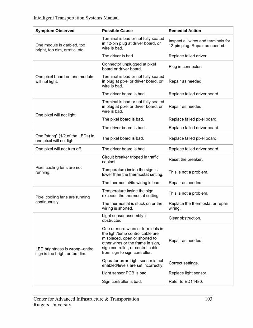
Intelligent Transportation Systems Manual
Center for Advanced Infrastructure & Transportation 103 Rutgers University
Symptom Observed Possible Cause Remedial Action
Terminal is bad or not fully seated in 12-pin plug at driver board, or wire is bad.
Inspect all wires and terminals for 12-pin plug. Repair as needed. One module is garbled, too
bright, too dim, erratic, etc. The driver is bad. Replace failed driver.
Connector unplugged at pixel board or driver board. Plug in connector.
Terminal is bad or not fully seated in plug at pixel or driver board, or wire is bad.
Repair as needed. One pixel board on one module will not light.
The driver board is bad. Replace failed driver board.
Terminal is bad or not fully seated in plug at pixel or driver board, or wire is bad.
Repair as needed.
The pixel board is bad. Replace failed pixel board. One pixel will not light.
The driver board is bad. Replace failed driver board.
One "string" (1/2 of the LEDs) in one pixel will not light. The pixel board is bad. Replace failed pixel board.
One pixel will not turn off. The driver board is bad. Replace failed driver board.
Circuit breaker tripped in traffic cabinet. Reset the breaker.
Temperature inside the sign is lower than the thermostat setting. This is not a problem.
Pixel cooling fans are not running.
The thermostat/its wiring is bad. Repair as needed.
Temperature inside the sign exceeds the thermostat setting. This is not a problem.
Pixel cooling fans are running continuously. The thermostat is stuck on or the
wiring is shorted. Replace the thermostat or repair wiring.
Light sensor assembly is obstructed. Clear obstruction.
One or more wires or terminals in the light/temp control cable are misplaced, open or shorted to other wires or the frame in sign, sign controller, or control cable from sign to sign controller.
Repair as needed.
Operator error-Light sensor is not enabled/levels are set incorrectly. Correct settings.
Light sensor PCB is bad. Replace light sensor.
LED brightness is wrong--entire sign is too bright or too dim.
Sign controller is bad. Refer to ED14480.
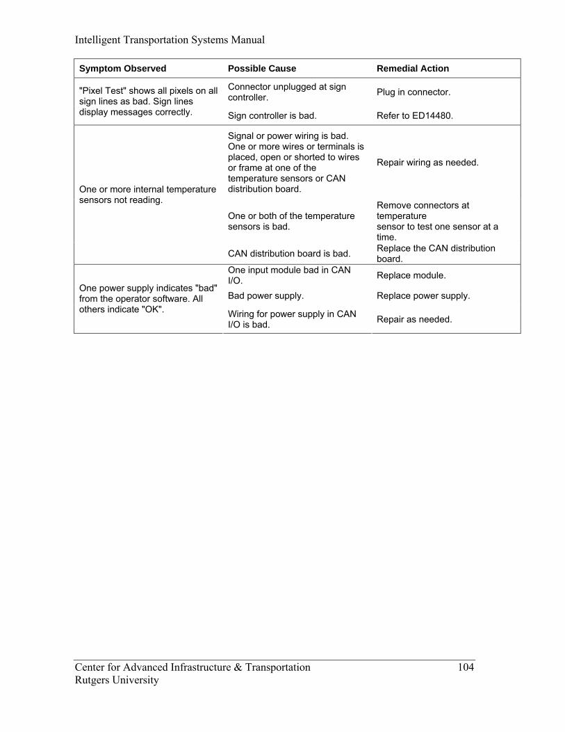
Intelligent Transportation Systems Manual
Center for Advanced Infrastructure & Transportation 104 Rutgers University
Symptom Observed Possible Cause Remedial Action
Connector unplugged at sign controller. Plug in connector. "Pixel Test" shows all pixels on all
sign lines as bad. Sign lines display messages correctly. Sign controller is bad. Refer to ED14480.
Signal or power wiring is bad. One or more wires or terminals is placed, open or shorted to wires or frame at one of the temperature sensors or CAN distribution board.
Repair wiring as needed.
One or both of the temperature sensors is bad.
Remove connectors at temperature sensor to test one sensor at a time.
One or more internal temperature sensors not reading.
CAN distribution board is bad. Replace the CAN distribution board.
One input module bad in CAN I/O. Replace module.
Bad power supply. Replace power supply. One power supply indicates "bad" from the operator software. All others indicate "OK". Wiring for power supply in CAN
I/O is bad. Repair as needed.
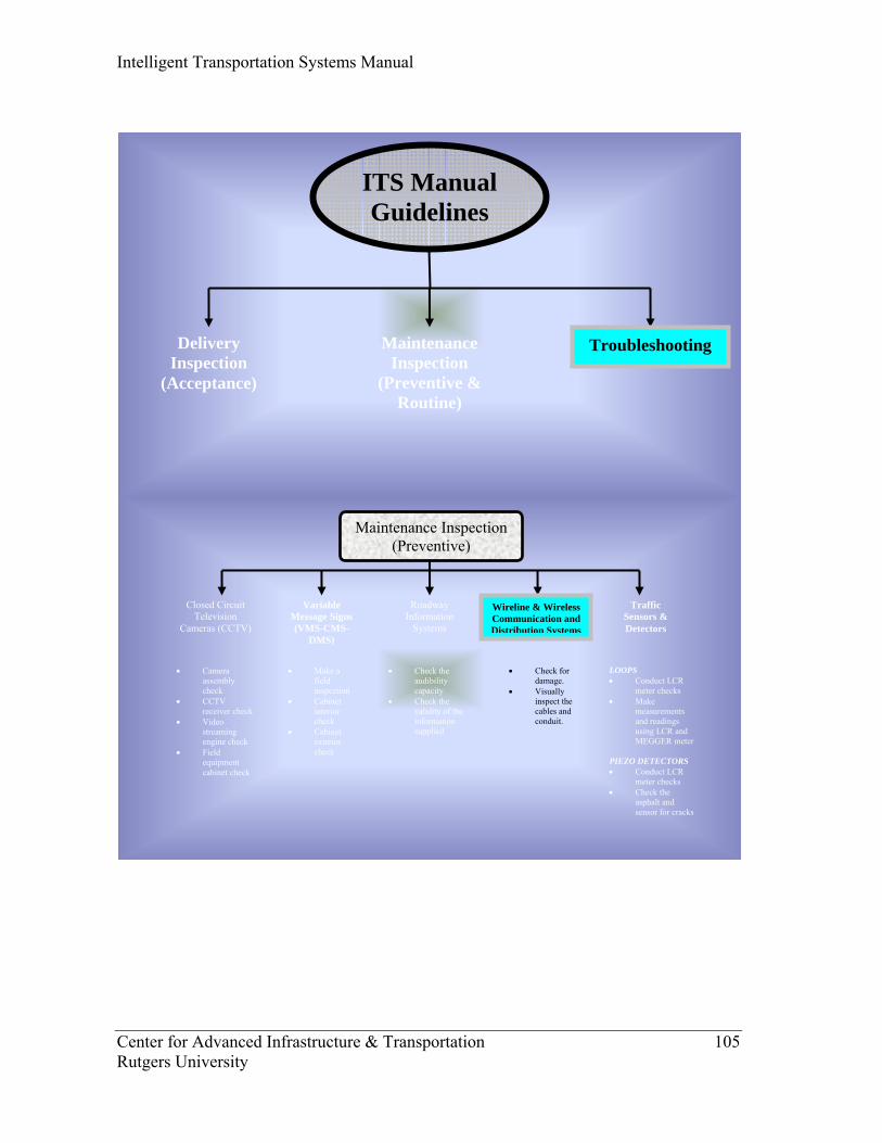
Intelligent Transportation Systems Manual
Center for Advanced Infrastructure & Transportation 105 Rutgers University
Closed Circuit Television
Cameras (CCTV)
Maintenance Inspection (Preventive)
Variable Message Signs (VMS-CMS-
DMS)
Traffic Sensors & Detectors
Roadway Information
Systems
• Camera assembly check
• CCTV receiver check
• Video streaming engine check
• Field equipment cabinet check
• Make a field inspection
• Cabinet interior check
• Cabinet exterior check
• Check the audibility capacity
• Check the validity of the information supplied
LOOPS • Conduct LCR
meter checks • Make
measurements and readings using LCR and MEGGER meter
PIEZO DETECTORS • Conduct LCR
meter checks • Check the
asphalt and sensor for cracks
Wireline & Wireless Communication and Distribution Systems
• Check for damage.
• Visually inspect the cables and conduit.
ITS Manual Guidelines
Delivery Inspection
(Acceptance)
TroubleshootingMaintenance Inspection
(Preventive & Routine)

Intelligent Transportation Systems Manual
Center for Advanced Infrastructure & Transportation 106 Rutgers University
Comlux Opt. Transmission Terminals – Models CL3683/CL3684
System failures in Force Incorporated Comlux equipment generally result from a single
point of failure. Depending on the location of the failure, alarms may propagate
throughout the system and appear on the affected unit. In order to minimize
troubleshooting time, these alarms are used as an aid in identifying failure location. Other
common problems include a lack of continuity in the optical fiber, lack of power (or
reversed power), or improper input levels.
There are no user-serviceable parts inside the equipment. In order to prevent shock
hazard, avoid opening the cover. If the cover must be opened to change switch settings,
first contact Customer Service who will make an entry in the equipment’s service log to
prevent possible voiding of the warranty. Before opening the cover, disable the
incoming power line and wait 10 minutes for interval voltages to discharge.
Troubleshooting usually consists of observing the lighted indicator on the front panel (or
its equivalent display if remove alarm monitoring is used) and correcting the condition.
Some problems and solutions are displayed below.
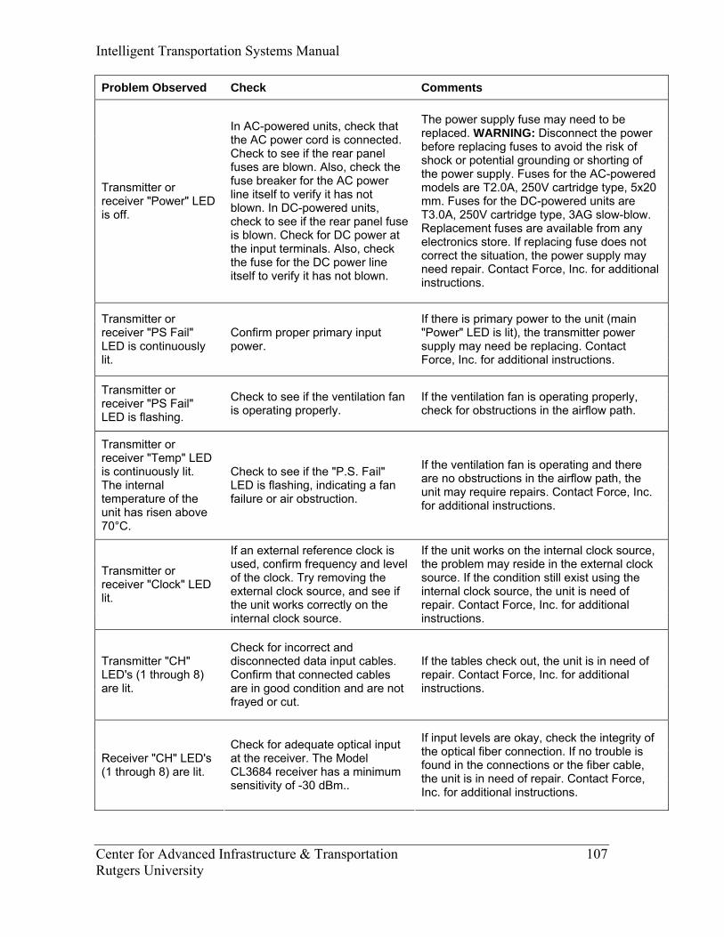
Intelligent Transportation Systems Manual
Center for Advanced Infrastructure & Transportation 107 Rutgers University
Problem Observed Check Comments
Transmitter or receiver "Power" LED is off.
In AC-powered units, check that the AC power cord is connected. Check to see if the rear panel fuses are blown. Also, check the fuse breaker for the AC power line itself to verify it has not blown. In DC-powered units, check to see if the rear panel fuse is blown. Check for DC power at the input terminals. Also, check the fuse for the DC power line itself to verify it has not blown.
The power supply fuse may need to be replaced. WARNING: Disconnect the power before replacing fuses to avoid the risk of shock or potential grounding or shorting of the power supply. Fuses for the AC-powered models are T2.0A, 250V cartridge type, 5x20 mm. Fuses for the DC-powered units are T3.0A, 250V cartridge type, 3AG slow-blow. Replacement fuses are available from any electronics store. If replacing fuse does not correct the situation, the power supply may need repair. Contact Force, Inc. for additional instructions.
Transmitter or receiver "PS Fail" LED is continuously lit.
Confirm proper primary input power.
If there is primary power to the unit (main "Power" LED is lit), the transmitter power supply may need be replacing. Contact Force, Inc. for additional instructions.
Transmitter or receiver "PS Fail" LED is flashing.
Check to see if the ventilation fan is operating properly.
If the ventilation fan is operating properly, check for obstructions in the airflow path.
Transmitter or receiver "Temp" LED is continuously lit. The internal temperature of the unit has risen above 70°C.
Check to see if the "P.S. Fail" LED is flashing, indicating a fan failure or air obstruction.
If the ventilation fan is operating and there are no obstructions in the airflow path, the unit may require repairs. Contact Force, Inc. for additional instructions.
Transmitter or receiver "Clock" LED lit.
If an external reference clock is used, confirm frequency and level of the clock. Try removing the external clock source, and see if the unit works correctly on the internal clock source.
If the unit works on the internal clock source, the problem may reside in the external clock source. If the condition still exist using the internal clock source, the unit is need of repair. Contact Force, Inc. for additional instructions.
Transmitter "CH" LED's (1 through 8) are lit.
Check for incorrect and disconnected data input cables. Confirm that connected cables are in good condition and are not frayed or cut.
If the tables check out, the unit is in need of repair. Contact Force, Inc. for additional instructions.
Receiver "CH" LED's (1 through 8) are lit.
Check for adequate optical input at the receiver. The Model CL3684 receiver has a minimum sensitivity of -30 dBm..
If input levels are okay, check the integrity of the optical fiber connection. If no trouble is found in the connections or the fiber cable, the unit is in need of repair. Contact Force, Inc. for additional instructions.

Intelligent Transportation Systems Manual
Center for Advanced Infrastructure & Transportation 108 Rutgers University
Comlux Optical Video Digital Codecs – Models CL3803/CL3804
System failures in Force Incorporated Comlux equipment generally result from a single
point of failure. Depending on the location of the failure, alarms may propagate
throughout the system and appear on the affected unit. In order to minimize
troubleshooting time, these alarms are used as an aid in identifying failure location.
Troubleshooting usually consists of observing the lighted indicator on the front panel (or
its equivalent display if remove alarm monitoring is used) and correcting the condition.
There are no user-serviceable parts inside the equipment. In order to prevent shock
hazard, avoid opening the cover. If the cover must be opened to change switch settings,
first contact Customer Service who will make an entry in the equipment’s service log to
prevent possible voiding of the warranty. Before opening the cover, disable the
incoming power line and wait 10 minutes for interval voltages to discharge.
The following troubleshooting information assumes that the system has been configured
in its most basic form, i.e. without any intermediate signal processing such as digital fan-
outs and digital switches. The described problems are as seen at the output of the CL3804
Video Decoder.
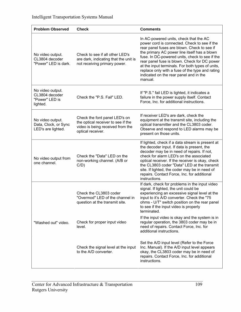
Intelligent Transportation Systems Manual
Center for Advanced Infrastructure & Transportation 109 Rutgers University
Problem Observed Check Comments
No video output. CL3804 decoder "Power" LED is dark.
Check to see if all other LED's are dark, indicating that the unit is not receiving primary power.
In AC-powered units, check that the AC power cord is connected. Check to see if the rear panel fuses are blown. Check to see if the primary AC power line itself has a blown fuse. In DC-powered units, check to see if the rear panel fuse is blown. Check for DC power at the input terminals. For both types of units, replace only with a fuse of the type and rating indicated on the rear panel and in the manual.
No video output. CL3804 decoder "Power" LED is lighted.
Check the "P.S. Fail" LED. If "P.S." fail LED is lighted, it indicates a failure in the power supply itself. Contact Force, Inc. for additional instructions.
No video output. Data, Clock, or Sync LED's are lighted.
Check the font panel LED's on the optical receiver to see if the video is being received from the optical receiver.
If receiver LED's are dark, check the equipment at the transmit site, including the optical transmitter and the CL3803 coder. Observe and respond to LED alarms may be present on those units.
No video output from one channel.
Check the "Data" LED on the non-working channel. (A/B or C/D)
If lighted, check if a data stream is present at the decoder input. If data is present, the decoder may be in need of repairs. If not, check for alarm LED's on the associated optical receiver. If the receiver is okay, check the CL3803 coder "Data" LED at the transmit site. If lighted, the coder may be in need of repairs. Contact Force, Inc. for additional instructions.
Check the CL3803 coder "Overmod" LED of the channel in question at the transmit site.
If dark, check for problems in the input video signal. If lighted, the unit could be experiencing an excessive signal level at the input to it’s A/D converter. Check the "75 ohms - U/T" switch position on the rear panel to see if the input video is properly terminated.
Check for proper input video level.
If the input video is okay and the system is in regular operation, the 3803 coder may be in need of repairs. Contact Force, Inc. for additional instructions.
"Washed out" video.
Check the signal level at the input to the A/D converter.
Set the A/D input level (Refer to the Force Inc. Manual). If the A/D input level appears okay, the CL3803 coder may be in need of repairs. Contact Force, Inc. for additional instructions.
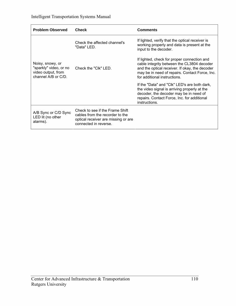
Intelligent Transportation Systems Manual
Center for Advanced Infrastructure & Transportation 110 Rutgers University
Problem Observed Check Comments
Check the affected channel's "Data" LED.
If lighted, verify that the optical receiver is working properly and data is present at the input to the decoder.
Check the "Clk" LED.
If lighted, check for proper connection and cable integrity between the CL3804 decoder and the optical receiver. If okay, the decoder may be in need of repairs. Contact Force, Inc. for additional instructions.
Noisy, snowy, or "sparkly" video, or no video output, from channel A/B or C/D.
If the "Data" and "Clk" LED's are both dark, the video signal is arriving properly at the decoder, the decoder may be in need of repairs. Contact Force, Inc. for additional instructions.
A/B Sync or C/D Sync LED lit (no other alarms).
Check to see if the Frame Shift cables from the recorder to the optical receiver are missing or are connected in reverse.
Intelligent Transportation Systems Manual
Center for Advanced Infrastructure & Transportation 111 Rutgers University
Comlux Optical Regenerators – Models CL3687/CL3687E System failures in Force Incorporated Comlux equipment generally result from a single
point of failure. Depending on the location of the failure, alarms may propagate
throughout the system and appear on the affected unit. In order to minimize
troubleshooting time, these alarms are used as an aid in identifying failure location. Other
common problems include a lack of continuity in the optical fiber, lack of power (or
reversed power), or improper input levels.
There are no user-serviceable parts inside the equipment. In order to prevent shock
hazard, avoid opening the cover. If the cover must be opened to change switch settings,
first contact Customer Service who will make an entry in the equipment’s service log to
prevent possible voiding of the warranty. Before opening the cover, disable the
incoming power line and wait 10 minutes for interval voltages to discharge.
Troubleshooting usually consists of observing the lighted indicator on the front panel (or
its equivalent display if remove alarm monitoring is used) and correcting the condition.
Some problems and solutions are displayed below.
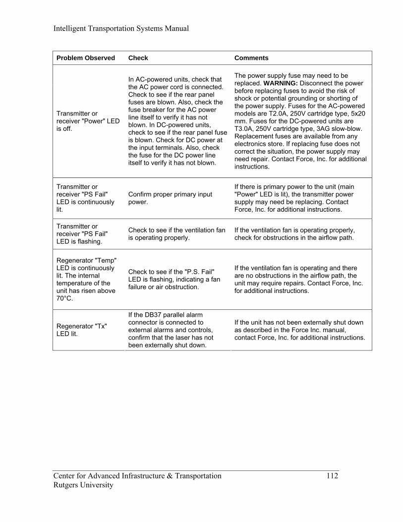
Intelligent Transportation Systems Manual
Center for Advanced Infrastructure & Transportation 112 Rutgers University
Problem Observed Check Comments
Transmitter or receiver "Power" LED is off.
In AC-powered units, check that the AC power cord is connected. Check to see if the rear panel fuses are blown. Also, check the fuse breaker for the AC power line itself to verify it has not blown. In DC-powered units, check to see if the rear panel fuse is blown. Check for DC power at the input terminals. Also, check the fuse for the DC power line itself to verify it has not blown.
The power supply fuse may need to be replaced. WARNING: Disconnect the power before replacing fuses to avoid the risk of shock or potential grounding or shorting of the power supply. Fuses for the AC-powered models are T2.0A, 250V cartridge type, 5x20 mm. Fuses for the DC-powered units are T3.0A, 250V cartridge type, 3AG slow-blow. Replacement fuses are available from any electronics store. If replacing fuse does not correct the situation, the power supply may need repair. Contact Force, Inc. for additional instructions.
Transmitter or receiver "PS Fail" LED is continuously lit.
Confirm proper primary input power.
If there is primary power to the unit (main "Power" LED is lit), the transmitter power supply may need be replacing. Contact Force, Inc. for additional instructions.
Transmitter or receiver "PS Fail" LED is flashing.
Check to see if the ventilation fan is operating properly.
If the ventilation fan is operating properly, check for obstructions in the airflow path.
Regenerator "Temp" LED is continuously lit. The internal temperature of the unit has risen above 70°C.
Check to see if the "P.S. Fail" LED is flashing, indicating a fan failure or air obstruction.
If the ventilation fan is operating and there are no obstructions in the airflow path, the unit may require repairs. Contact Force, Inc. for additional instructions.
Regenerator "Tx" LED lit.
If the DB37 parallel alarm connector is connected to external alarms and controls, confirm that the laser has not been externally shut down.
If the unit has not been externally shut down as described in the Force Inc. manual, contact Force, Inc. for additional instructions.
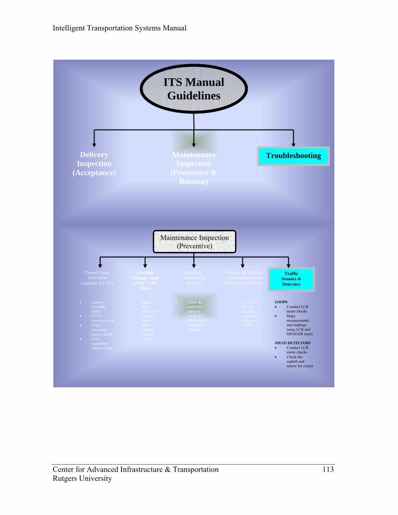
Intelligent Transportation Systems Manual
Center for Advanced Infrastructure & Transportation 113 Rutgers University
Closed Circuit Television
Cameras (CCTV)
Maintenance Inspection (Preventive)
Variable Message Signs (VMS-CMS-
DMS)
Traffic Sensors & Detectors
Roadway Information
Systems
• Camera assembly check
• CCTV receiver check
• Video streaming engine check
• Field equipment cabinet check
• Make a field inspection
• Cabinet interior check
• Cabinet exterior check
• Check the audibility capacity
• Check the validity of the information supplied
LOOPS • Conduct LCR
meter checks • Make
measurements and readings using LCR and MEGGER meter
PIEZO DETECTORS • Conduct LCR
meter checks • Check the
asphalt and sensor for cracks
Wireline & Wireless Communication and Distribution Systems
• Check for damage.
• Visually inspect the cables and conduit.
ITS Manual Guidelines
Delivery Inspection
(Acceptance)
TroubleshootingMaintenance Inspection
(Preventive & Routine)
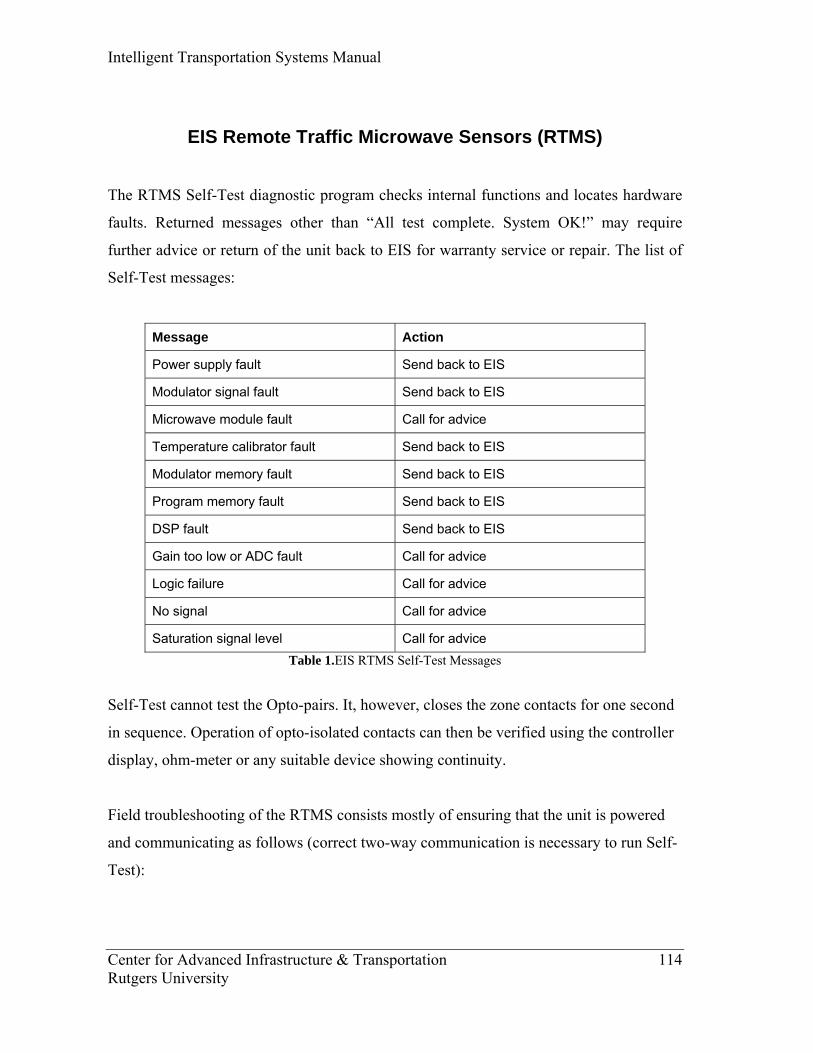
Intelligent Transportation Systems Manual
Center for Advanced Infrastructure & Transportation 114 Rutgers University
EIS Remote Traffic Microwave Sensors (RTMS)
The RTMS Self-Test diagnostic program checks internal functions and locates hardware
faults. Returned messages other than “All test complete. System OK!” may require
further advice or return of the unit back to EIS for warranty service or repair. The list of
Self-Test messages:
Message Action
Power supply fault Send back to EIS
Modulator signal fault Send back to EIS
Microwave module fault Call for advice
Temperature calibrator fault Send back to EIS
Modulator memory fault Send back to EIS
Program memory fault Send back to EIS
DSP fault Send back to EIS
Gain too low or ADC fault Call for advice
Logic failure Call for advice
No signal Call for advice
Saturation signal level Call for advice Table 1.EIS RTMS Self-Test Messages
Self-Test cannot test the Opto-pairs. It, however, closes the zone contacts for one second
in sequence. Operation of opto-isolated contacts can then be verified using the controller
display, ohm-meter or any suitable device showing continuity.
Field troubleshooting of the RTMS consists mostly of ensuring that the unit is powered
and communicating as follows (correct two-way communication is necessary to run Self-
Test):

Intelligent Transportation Systems Manual
Center for Advanced Infrastructure & Transportation 115 Rutgers University
Symptom Observed Possible Cause Remedial Action
Check cable connections for continuity and/or wiring errors.
Check that the supply voltage is within limits of EIS RTMS Manual. Voltage outside of limits (too low or too high) will cause power supply to shut down. **Sensor Inactive** message is
displayed. Power failure With the PC connected from RTMS, check the RTMS serial bus by measuring -10V between pins 2 and 5 of the DB9 RS-232 connector. If voltage is not present, the unit is not powered or there is a hardware fault in the RTMS serial port. Hit any key. If target blips are present, refer to the next problem.
Check that the RTMS serial port is connected to the PC COM 1 port. Check that COM port is available and not used by another application (e.g. serial mouse).
**Sensor Inactive** message is displayed.
PC unable to communicate with the RTMS
Check whether a second setup program is running and locking out the serial port.
Main screen shows target blips but no zones and all zero statistics.
PC receives RTMS data without PC requests.
Check PC's serial port (-10V between pins 3 and 5)
"Cannot read setup" message displayed.
RTMS serial port is unable to receive requests from PC.
Check cable.
Self-Test initiated but results are not displayed on PC screen. Send unit to EIS for repair if PC and cables
are OK.
RTMS is not in NORMAL mode.
Ensure the unit is in the NORMAL mode (DATA menu).
Unit is not aimed properly.
Generate a target by waiving a hand in front of the unit. If a blip does not appear, a hardware fault may be present.
Low Sensitivity Check sensitivity setting. See if targets appear when sensitivity increased.
Internal parameters are corrupted.
Recycle power to unit. Load a prepared file on supplied software disks (e.g. FWDLK) and then edit parameters (mode, sensitivity, zone set-up, etc)
Main screen is displayed on program initiation (i.e. PC and sensor are communicating) but target "blips" are not shown.
Run Self-Test if above not successful. Report findings to EIS.