intelligent Touch Controller - Daikin · 2020-03-08 · 3 System Overview This intelligent Touch...
98
Operation Manual Use smart and save smart • Thank you for purchasing intelligent Touch Controller. • This operation manual contains notes for safe use of the product. For correct use, be sure to read this manual carefully before use. • When you have read this manual, be sure to store it in a place where the operator can conveniently refer to at anytime. In case of personnel change, be sure to give the manual to the new operator. Model DCS601C51 intelligent Touch Controller Maintenance Precautions................................................ 83 Maintenance LCD Maintenance...................................... 84 When Leaving the Product Turned OFF for a Long Time ..................... 84 Troubleshooting ......................................... 85 Maintenance For Your Information Before use Operation Before use Safety Considerations Be sure to follow the instructions below ..... 1 System Overview......................................... 3 Features and Functions ............................... 4 Part Names and Functions .......................... 5 Part Names on the Monitoring Screen and the Functions List ............................................................... 7 Icon.............................................................. 9 Operation Operation Quick Reference ........................................ 13 Air Conditioner Operation .......................... 15 Monitoring Operation of Air Conditioner ... 26 System Setup Menu ..................................... 32 For Your Information Options ...................................................... 93 Specification .............................................. 94 After-sales Service .....................................95 EM04A055A
Transcript of intelligent Touch Controller - Daikin · 2020-03-08 · 3 System Overview This intelligent Touch...

Operation Manual
Use smart and save smart
• Thank you for purchasing intelligent Touch Controller.
• This operation manual contains notes for safe use of the product.For correct use, be sure to read this manual carefully before use.
• When you have read this manual, be sure to store it in a place where the operator can conveniently refer to at anytime. In case of personnel change, be sure to give the manual to the new operator.
Model
DCS601C51
intelligent Touch Controller
MaintenancePrecautions................................................ 83MaintenanceLCD Maintenance...................................... 84When Leaving the Product Turned OFF for a Long Time ..................... 84Troubleshooting .........................................85 M
aint
enan
ceFo
r You
r Inf
orm
atio
nB
efor
e us
eO
pera
tion
Before useSafety ConsiderationsBe sure to follow the instructions below .....1
System Overview......................................... 3
Features and Functions...............................4
Part Names and Functions.......................... 5
Part Names on the Monitoring
Screen and the FunctionsList ............................................................... 7Icon.............................................................. 9
OperationOperation
Quick Reference........................................13
Air Conditioner Operation .......................... 15
Monitoring Operation of Air Conditioner ... 26
System Setup Menu ..................................... 32
For Your InformationOptions ...................................................... 93
Specification .............................................. 94
After-sales Service .....................................95
EM04A055A

Operation Manual
Use smart and save smart
• Thank you for purchasing intelligent Touch Controller.
• This operation manual contains notes for safe use of the product.For correct use, be sure to read this manual carefully before use.
• When you have read this manual, be sure to store it in a place where the operator can conveniently refer to at anytime. In case of personnel change, be sure to give the manual to the new operator.
Model
DCS601C51
intelligent Touch Controller
MaintenancePrecautions................................................ 83MaintenanceLCD Maintenance...................................... 84When Leaving the Product Turned OFF for a Long Time ..................... 84Troubleshooting .........................................85 M
aint
enan
ceFo
r You
r Inf
orm
atio
nB
efor
e us
eO
pera
tion
Before useSafety ConsiderationsBe sure to follow the instructions below .....1
System Overview......................................... 3
Features and Functions...............................4
Part Names and Functions.......................... 5
Part Names on the Monitoring
Screen and the FunctionsList ............................................................... 7Icon.............................................................. 9
OperationOperation
Quick Reference........................................13
Air Conditioner Operation .......................... 15
Monitoring Operation of Air Conditioner ... 26
System Setup Menu ..................................... 32
For Your InformationOptions ...................................................... 93
Specification .............................................. 94
After-sales Service .....................................95

Warning
Warning
caution
Note
Safety Considerations
Please read these “SAFETY CONSIDERATIONS” carefully before installing air conditioning equipment and be sure to install it correctly. After completing the installation, make sure that the unit operates properly during the start-up operation.Please instruct the customer on how to operate the unit and keep it maintained.Also, inform customers that they should store this installation manual along with the operation manual for future reference.This air conditioner comes under the term “appliances not accessible to the general public”.
Meaning of warning, caution and note symbols.
Indicates a potentially hazardous situation which, if not avoided, could result in death or serious injury.
Indicates a potentially hazardous situation which, if not avoided, may result in minor or moderate injury. It may also be used to alert against unsafe practices.
Indicates situation that may result in equipment or property-damage-only accidents.
Keep these warning sheets handy so that you can refer to them if needed.Also, if this equipment is transferred to a new user, make sure to hand over this operation manual to the new user.
In order to avoid electric shock, fire or injury, or if you detect any abnormality such as smell of fire, turn off power and call your dealer for instructions.
Ask your dealer for installation of the air conditioner.Incomplete installation performed by yourself may result in a water leakage, electric shock, and fire.Ask your dealer for improvement, repair, and maintenance.Incomplete improvement, repair, and maintenance may result in a water leakage, electric shock, and fire.
Improper installation or attachment of equipment or accessories could result in electric shock, short-circuit, leaks, fire or other damage to the equipment. Be sure only to use accessories made by Daikin which are specifically designed for use with the equipment and have them installed by a professional.
Ask your dealer to move and reinstall the air con-ditioner or the remote controller.
Incomplete installation may result in a water leakage, electric shock, and fire.
Never let the indoor unit or the remote controller get wet. It may cause an electric shock or a fire.
Never use flammable spray such as hair spray, lacquer or paint near the unit.It may cause a fire.
Never replace a fuse with that of wrong ampere ratings or other wires when a fuse blows out.Use of wire or copper wire may cause the unit to break down or cause a fire.
Never inspect or service the unit by yourself.Ask a qualified service person to perform this work.
Cut off all electric waves before maintenance.Do not wash the air conditioner or the remote controller with excessive water.Electric shock or fire may result.Do not install the air conditioner or the remote controller at any place where flammable gas may leak out.If the gas leaks out and stays around the air condi-tioner, a fire may break out.
Do not touch the switch with wet fingers.Touching a switch with wet fingers can cause electric shock.
CISPR 22 Class A Warning:This is a class A product. In a domestic environment this prod-uct may cause radio interference in which case the user may be required to take adequate measures.
1

After a long use, check the unit stand and fitting for damage.If they are left in a damaged condition, the unit may fall and result in injury.
Do not allow a child to mount on the unit or avoid placing any object on it.Falling or tumbling may result in injury.
Do not let children play on and around the unit.If they touch the unit carelessly, it may result in injury.
Do not place a flower vase and anything contain-ing water.Water may enter the unit, causing an electric shock or fire.
Never touch the internal parts of the controller.Do not remove the front panel. Some parts inside are dan-gerous to touch, and a machine trouble may happen. For checking and adjusting the internal parts, contact your dealer.
Avoid placing the controller in a spot splashed with water.Water coming inside the machine may cause an electric leak or may damage the internal electronic parts.
Do not operate the air conditioner when using a room fumigation - type insecticide.Failure to observe could cause the chemicals to become deposited in the unit, which could endanger the health of those who are hypersensitive to chemicals.
Safely dispose of the packing materials.Packing materials, such as nails and other metal or wooden parts, may cause stabs or other injuries.Tear apart and throw away plastic packaging bags so that children will not play with them. If children play with a plastic bag which was not torn apart, they face the risk of suffocation.
Do not turn off the power immediately after stop-ping operation.Always wait at least five minutes before turning off the power. Otherwise, water leakage and trouble may occur.
The appliance is not intended for use by young children or infirm persons without supervision.The remote controller should be installed in such away that children cannot play with it.
Never press the button of the remote controller with a hard, pointed object.The remote controller may be damaged.
Never pull or twist the electric wire of the remote controller.It may cause the unit to malfunction.
Do not place the controller exposed to direct sunlight.The LCD display may get discolored, failing to dis-play the data.
Do not wipe the controller operation panel with benzine, thinner, chemical dustcloth, etc.The panel may get discolored or the coating peeled off. If it is heavily dirty, soak a cloth in water-diluted neutral detergent, squeeze it well and wipe the panel clean. And wipe it with another dry cloth.
Dismantling of the unit, treatment of the refriger-ant, oil and eventual other parts, should be done in accordance with the relevant local and national regulations.
2
CAUTION NOTE

3
System Overview
This intelligent Touch Controller is capable of controlling / monitoring up to 64 groups of indoor units (hereafter “groups”).
The main functions of the intelligent Touch Controller include :1. Collective starting / stopping of operation of the indoor units connected to the intelligent Touch Controller.2. Starting / stopping of operation, temperature setting, switching between temperature control modes and
enabling / disabling of operation with the hand-held remote control by zone or group .3. Scheduling by zone or group .4. Monitoring of the operation status by zone or group .5. Display of the air conditioner operation history.6. Compulsory contact stop input from the central monitoring panel (non-voltage, normally-open contact).7. Power distribution of the air conditioners. (With the optional DCS002A51)
∗ A group of indoor units include :
∗ Zone control with the intelligent Touch Controller
1 One indoor unit without a remote control.
3 Up to 16 indoor units controlled with one or two remote controls.
2 One indoor unit controlled with one or two remote controls.
intelligent Touch Controller
Zone 1
Up to 16 units Up to 16 unitsTwo remote controlsRemote control
No remote controlRemote control Remote control
or
Indoor unit
Zone 5
Zone 2 Zone 3 Zone 4
∗ Zone control, which allows collective settings for more than one group, is available with the intelligent Touch Controller, which facilitates the setting operations.
• One setting makes the same setting for all of the units in one zone.• Up to 128 zones can be set with one intelligent Touch Controller. (The maximum number of groups in one zone is 64.)• Groups can be zoned at will with the intelligent Touch Controller.• Units in one group can be divided into more than one zone.

4
Features and Functions
■ Operation Menuintelligent Touch Controller is capable of starting / stopping of the operation by the group or zone. Collective starting / stopping is also available.
■ Air Conditioner Detail SetupTemperature setting, switching between temperature control modes, switching of speed and direction of wind and remote control mode setting are available by the group, by the zone or collectively.
■ Monitoring of Various Information on Indoor UnitsInformation on operation such as the operation mode and temperature setting of the indoor units, maintenance information including the filter or element cleaning sign, troubleshooting information such as error codes can be displayed by the group or the zone.
■ Zone Control Simplifying Complicated Setting OperationsUp to 64 groups can be controlled with the intelligent Touch Controller.More than one group can be consolidated into a zone, which can be registered, to allow the following settings by the zone. This eliminates the need for repeating the same setting operation for each group. Function to allow collective setting for all groups is also available.
■ Detailed Scheduled Operation ControlThe intelligent Touch Controller allows detailed scheduled operation by the group, by the zone or collectively. Up to 8 options for annual schedule can be set. Each schedule can include four types of plans : for Weekdays, Holidays, Special days 1 and Special days 2. Each of the plans allows setting of up to 16 operations.
■ Diversified Operation ModesOperation can be controlled both with the main unit and the remote control to provide diversified operation management. Setting with the main unit allows the following remote control settings by the group, by the zone or collectively:1. Start/Stop 2. Operation Mode 3.Temperature Setting
: (Remote control) Inhibited : (Remote control) Inhibited : (Remote control) Inhibited: (Remote control) Permitted : (Remote control) Permitted : (Remote control) Permitted: Priority
• Start / stop• Temperature setting• Switching between operation modes• Setting of direction and fan speed• Disabling / enabling the remote control
See pages
15 17to
See pages
18 22to
See pages
26 29to
See page 22
See pages
15 29to
33
See pages
35 36to
See pages
37 46to
■ Handy Automated ControlThe Intelligent Touch Controller can do the following.• Change Over Settings : automatically switches between cooling and heating
according to the room temperature.• Temperature Limit Settings : prevents the temperature from rising too high or
too low in unmanned rooms.• Heating Optimization Settings : stops uncomfortable hot air from blowing when
the heating thermo is off.

Be sure to use the touch pen for operation of the touch panel of the intelligent Touch Controller.Operating with an object other than the touch pen provided may cause damage and failure.
Part Names and Functions
Color LCD with Touch PanelProvides a display for monitoring and operation.Be sure to use the touch pen provided for operation.
PCMCIA Card SlotUsed when using the optional Power Proportional Distribution (DCS002C51) or updating the intelligent Touch Controller software to a newer version.
Touch Pen
5
Use the touch pen for operation.Be sure to use the touch pen for operation.Use caution not to lose the touch pen.When the pen is lost, contact the dealer you purchased the product from.
Front and Side View
Note

Terminals on the Back of intelligent Touch Controller
Using DIII-NET Plus adapter being sold as an accessory, you can increase the number of indoor units to be controlled.
RS232-C connector for DIII-NET Plus adapter
When using AIRNET service, connect it to the telephone line.
Modem connector for AIRNET
This is used when distributing the power supply to indoor units using optional Power Proportional Distribution software sold separately and when stopping the indoor units compulsorily by contact input.The size of terminal block is M3.5.
Terminal block for watt hour meter and force stop input of indoor units
When monitoring and operating the indoor units using the optional Web and E-mail function software sold separately, connect to LAN via Ethernet cable.
Ethernet connector for web
Securely connect the earth wire.Terminal size is M4.
Earth terminal block
Connect to AC100-240V power supply.Terminal size is M4.
Terminal block for power supply
The terminal size of the terminal block for communication with indoor units is M3.5.
Terminal block for DIII-NET communication
LINE
COM L0Dil Pi3 COM Pi2 Pi1 F2 F1 N L
PHONE
RS
-232CLA
N
6
Contents of the List Currently Displayed
• When Group List is displayed“Zone : Zone Name”
• When Zone List is displayed“Zone List”
Display Mode Selection
Press the button and display change between Zone and Group.
System Condition Displayed Domain
Domain displaying system condition (Compulsory Stop etc.)
Zone / Group Name
Set the names in the Group Registration or Zone Registration in the System Setup Mode.
Filter / Element Sign
Displayed when there is any air conditioner showing a filter or element sign in the zone or the group.
Target of Automatic Control
Displayed when there is any air conditioner with the registration of scheduled in the zone or in the group.
Monitoring Screen Legend
Pressing the “?” button shows more detailed legend. Button to Switch to the System Setup Mode
Use this button for settings including the time, group, zone and schedule.
7
Part Names on the Monitoring Screen and the Functions
List
Zone / Group Currently Displayed
The name of the zone / group currently selected is highlightedin light-blue.

8
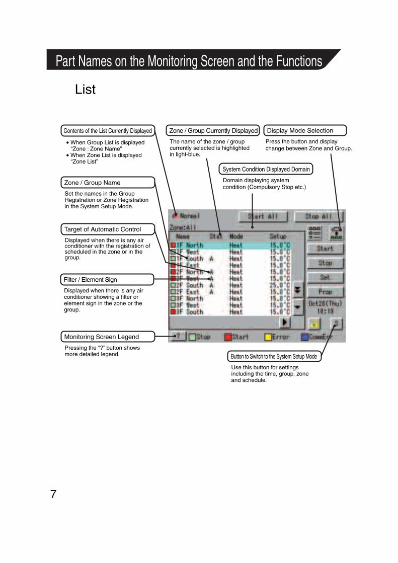
ListDisplay for Collective Monitoring of AirConditioners Connected to intelligent Touch Controller
When operation is normal and any air conditioner is in operation :
Red / NormalWhen operation is normal and all air conditioners are in stoppage :
Green / Normal When there is any air conditioner generating an error :
Yellow / AbnormalWhen there is any air conditioner with communication error :
Blue / AbnormalChange in color of Start/Stop is possible by Iconcolor Settings in System Settings.
Start All Button
Button to collectively start all the air conditioners connected to intelligent Touch Controller.
Stop All Button
Button to collectively stop all the air conditioners connected to intelligent Touch Controller.
Display Mode Selection
Select the mode among icon / list / detailed icon.Displayed in List in the right figure.Icon display is P9, 10.Detailed icon display is P11, 12.
Group / Zone Start Button
Button to start operation of the group / zone selected.
Group / Zone Stop Button
Button to stop operation of the group / zone selected.
Group / Zone Set Button
Makes settings (temperature setting, temperature control mode, etc.) and display of the group / zone selected.
Current Time Display
Shows the current date and time.
Group / Zone Prop Button
Detailed display of the group / zone selected
Lock Setting / Cancel Button
Displays possibititiy of monitor operation.Expresses detailed information in P31, 32.
Scroll Buttons
Up / Down scroll button used when monitoring zone / group which are not currently displayed.Left/Right scroll button usedwhen monitoring temperatureand errors etc.Which are not currentlydisplayed.

Contents of the List Currently Displayed
• When Group List is displayed“Zone : Zone Name”
• When Zone List is displayed“Zone List Display”
Display Mode Selection
Select between Zone and Group.
Generally, the temperature setting and the operation mode are displayed. If any error occurs in the air conditioner, the error code is displayed.
Blue triangular mark shows communication abnormality in air conditioner.Yellow triangular mark shows abnormality in air conditioner.
Zone / Group Currently Displayed
The name of the zone / group currently selected is highlighted in blue flame.
Zone / Group Name
Set the names in the Group Registration or Zone Registration in the System Setup Mode.
Filter / Element Sign
Displayed when there is any air conditioner showing a filter or element sign in the zone or the group.
Target of Automatic Control
Displayed when there is any air conditioner with the registration of scheduled in the zone or in the group.
Monitoring Screen Legend
Pressing the “?” button shows more detailed legend.
Use this button for settings including the time, group, zone and schedule.
Description of Zone / Group
Set the names in the Group Registration or Zone Registration in the System Setup Mode.
9
Icon
System Condition Displayed Domain
Domain displaying system condition (Compulsory Stop etc.)
Information on Zone / Group Currently Displayed
Displayed Abnormality in Air Conditioner or Communication
Button to Switch to the System Setup Mode

10
IconDisplay for Collective Monitoring of AirConditioners Connected to intelligent Touch Controller
When operation is normal and any air conditioner is in operation :
Red / NormalWhen operation is normal and all air conditioners are in stoppage :
Green / Normal When there is any air conditioner generating an error :
Yellow / AbnormalWhen there is any air conditioner with communication error :
Blue / AbnormalChange in color of Start / Stop is possible by Iconcolor Settings in System Settings.
Start All Button
Button to collectively start all the air conditioners connected to intelligent Touch Controller.
Stop All Button
Button to collectively stop all the air conditioners connected to intelligent Touch Controller.
Display Mode Selection
Select the mode among icon / list / detailed icon.Displayed is List in the right figure.List display in P7, 8.Detailed icon display is P11, 12.
Group / Zone Start Button
Button to start operation of the group / zone selected.
Group / Zone Stop Button
Button to stop operation of the group / zone selected.
Group / Zone Set Button
Makes settings (temperature setting, temperature control mode, etc.) and display of the group / zone selected.
Current Time Display
Shows the current date and time.
Group / Zone Prop Button
Detailed display of the group / zone selected
Lock Setting / Cancel Button
Displays possibititiy of monitor operation.Expresses detailed information in P31, 32.
Scroll Buttons
Up / Down scroll button used when monitoring zone / group which are not currently displayed.Left / Right scroll button used when monitoring temperature and errors etc.Which are not currently displayed.

11
Icon
Contents of the List Currently Displayed
• When Group List is displayed“Zone : Zone Name”
• When Zone List is displayed“Zone List Display”
Display Mode Selection
Press the button ana display change between Zone and Group.
Blue triangular mark shows communication abnormality in air conditioner.Yellow triangular mark shows abnormality in air conditioner.
Zone / Group Currently Displayed
The name of the zone / group currently selected is highlighted in blue frame.
Zone / Group Name
Set the names in the Group Registration or Zone Registration in the System Setup Mode.
Filter / Element Sign
Displayed when there is any air conditioner showing a filter or element sign in the zone or the group.
Target of Automatic Control
Displayed when there is any air conditioner with the registration of scheduled in the zone or in the group.
Monitoring Screen Legend
Pressing the “?” button shows more detailed legend.
Button to Switch to the System Setup ModeUse this button for settings including the time, group, zone and schedule.
System Condition Displayed Domain
Domain displaying system condition (Compulsory Stop etc.).
Displayed Abnormality in Air Conditioner or Communication
12
Display for Collective Monitoring of AirConditioners Connected to intelligent Touch Controller
When operation is normal and any air conditioner is in operation :
Red / NormalWhen operation is normal and all air conditioners are in stoppage :
Green / Normal When there is any air conditioner generating an error :
Yellow / AbnormalWhen there is any air conditioner with communication error :
Blue / AbnormalChange in color of Start / Stop is possible by Iconcolor Settings in System Settings.
Start All Button
Button to collectively start all the air conditioners connected to intelligent Touch Controller.
Stop All Button
Button to collectively stop all the air conditioners connected to intelligent Touch Controller.
Display Mode Selection
Select the mode among icon / list / detailed icon.Displayed in List in the right figure.List display is P7, 8.Icon display is P9, 10.
Group / Zone Start Button
Button to start operation of the group / zone selected.
Group / Zone Stop Button
Button to stop operation of the group / zone selected.
Group / Zone Set Button
Makes settings (temperature setting, temperature control mode, etc.) and display of the group / zone selected.
Current Time Display
Shows the current date and time.
Group / Zone Prop Button
Detailed display of the group / zone selected
Lock Setting / Cancel Button
Displays possibititiy of monitor operation.Expresses detailed information in P31, 32.
Scroll Buttons
Up / Down scroll button used when monitoring zone/group which are not currently displayed.Left/Right scroll button usedwhen monitoring temperatureand errors etc.Which are not currentlydisplayed.
Icon

13
Quick Reference
15
16
17
18
19
20
21
22
23
24
25
26 27
28 29
30
31
Air Conditioner Operation
■ To collectively start / stop the operation of all devices connected to the intelligent Touch Controller
■ To start / stop the operation of devices by zone
■ To start / stop the operation of devices by group
■ To change the operation mode
■ To change the temperature setting
■ To change the direction or fan speed
■ To change the range of operation allowed with remote control
■ To change the ventilation mode
■ To change the ventilation volume
■ To permit / prohibit the remote control at hand for ventilation
Air Conditioner Operation Monitoring
■ To monitor by zone or by group
■ To monitor detailed information
■ To monitor the operation condition for ventilation
■ To set / release the lock of screen operation
■ To reset the filter or element sign
See page
See page
See page
See page
See page
See page
See page
See page
See page
See pages to
See pages to
See page
See page
See page
See page

14
33
33
35 36
37 41
42 44
45 46
55
55
34
34
34
34
92
47
50 54
49See pages to
System Setup Menu
■ To change the name of a group
■ To change the zone setup
■ To change the schedule setup
■ To calibrate the touch panel
■ To adjust the contrast of the screen
■ To set the e-mail
■ To review the history of errors
■ To set the locale
■ To set the icon color
■ To set the network
■ To set the license key
■ To change the change over settings
■ To change the temperature limit settings
■ To change the heating optimization settings
See page
See page
See pages to
See pages to
See pages to
See pages to
See pages to
See page
See page
See page
See page
See page
See page
See page
■ To xxxx

15
Air Conditioner Operation
Starting / Stopping Operation Collectively
1 2
3
Screen 1 Monitoring
Screen 2 Confirm
To start / stop the operation of all devices connected
1.
2. Screen 2 Confirm appears. Press the [OK] button 3 .To exit without activating collective start or stop, press the [Cancel] button.
Start or stop collectively the operation of devices connected.
On the Monitoring screen, operation is allowed with either Zone or Group as the display mode and with either Icon or List as the display type. In the example on the left, the display mode is Group in the collective mode and the display type is Icon.
[Procedure]
On Screen 1 Monitoring, press the [Start All] button 1 or [Stop All] button 2 .

16
Screen 1 Monitoring To start / stop the operation of devices by group
1.On Screen 1 Monitoring, select a zone from the button 1 .
Start or stop the operation of air conditioners by group.
The example on the left shows the screen for starting / stopping the operation of Group Name : 1F North registered for Zone Name : Canteen.
2. Select a zone that includes the group of which the operation is to be started or stopped 2 .
3.
4. Select a group to be started or stopped as in 3 and press the [Start] button 4 or [Stop] button 5 .
Starting / Stopping Operation by the Group
Screen 2 Monitoring (Group)
1
2
34
5
Zone Name
Canteen
[Procedure]
Air conditioner group to be started or stopped
1F North
1F West
1F South
1F East
2F North
2F West
2F South
2F East
3F North
Select a group from the button 1 .Screen 2 Monitoring (Group) appears.

17
Collective ZoneZone Name
Screen 1 Monitoring To start / stop the operation of devices by group
1.On Screen 1 Monitoring, select a zone from the button 1 .
2.
Starting / Stopping Operation by the Zone
1
3
4
2
Select the zone of which the operation is to be started / stopped as shown in 2 .
3. Press the [Start] button 3 or [Stop] button 4 .
Start or stop by zone the operation of groups of air conditioners set in zones.
The example on the left shows a screen for starting or stopping the operation of air conditioners in the canteen.
[Procedure]
Office
Canteen
Meeting
1F
2F
3F
Air conditioner group to be started or stopped

18
Screen 1 Monitoring
1.On Screen 1 Monitoring, select a zone or a group from the button 1 .
Switch the operation mode of the air conditioner.
On the Monitoring screen, operation is allowed with either Icon or List as the display type.
The operation mode can be switched by zone or by group.
Selecting a zone and switching the operation mode switches the mode of all air conditioners in the zone.Selecting a group and switching the operation mode switches the mode of air conditioners in the group selected.
Ex.: For the following zone setting, the operation modes available are Fan, Cool, Heat and Auto.If Cool/Heat option is not available for any air conditioner in the zone, Fan and Set Point are the available operation modes.
2. Select with 2 a zone or a group of which the operation mode is to be switched.
3. Press the [Set] button 3 .Screen 2 Operation appears.
4. Select the operation mode to be set from the pull down menu 4 .
5.
Switching the Operation Mode
Screen 2 Operation
3
2
5
1
4
To cancel the setting, press the Cancel button.
On the menu, operation modes available for air conditioners in the zone are displayed if the switching is to be made by zone. See the example below.
Press the [OK] button 5 .
Zone name Group name Operation modes available
Canteen 1F North
1F West
[Procedure]
“Cool” “Heat” “Auto” “Air”
“Cool” “Air”

19
Screen 1 Monitoring
1. On Screen 1 Monitoring, select a zone or a group from the button 1 .
Change the temperature setting of air conditioners.
On the Monitoring screen, operation is allowed with either Icon or List as the display type.
The temperature setting can be switched by zone or by group.
Selecting a zone and changing the temperature setting changes the setting of the air conditioner groups in Cool, Heat, Auto or Temp operation in the zone.
Selecting a group and changing the temperature setting changes the temperature setting of air conditioners in the group selected.
If all of the air conditioners in the group selected are in Fan operation, temperature setting cannot be changed.
2. Select a zone or a group of which the temperature setting is to be changed 2 .
3. Press the [Set] button 3 .Screen 2 Operation appears.
4. For temperature setting, press the [Modify] button 4 .Set Temperature dialog is displayed and input temperature for setting.
Ex.: For the following zone setting, the temperature settings available are between 20°C and 30°C inclusive.
When the temperature setting is 30°C, the actual temperature settings for air conditioners are as shown below:
Note: Range of temperature settings available is the range specified in accordance with the following. • Range of temperature setting inherent to
the air conditioner main unit. • Range of temperature as a result of the
restriction by the temperature setting limit.
5.
Changing the Temperature Setting
Screen 2 Operation
1
3
2
4
5
To cancel the setting, press the [Cancel] button.
On the menu, temperature settings available for air conditioners in the zone are displayed if the setting is to be made by the zone. See the example below.
Press the [OK] button 5 .
Zone name Group name
Group name Temperature setting
Canteen 1F North 25 to 30°C
20 to 25°C1F West
1F North 30°C
25°C1F West
[Procedure]
See page 60
Range of temperature settings available (see Note)

20
Screen 1 Monitoring
1.On Screen 1 Monitoring, select a zone or a group from the button 1 .
Reset the filter or element sign after cleaning any air conditioner showing the filter or element sign.
On the Monitoring screen, operation is allowed with either Icon or List as the display type.
The filter or element sign can be reset by zone or by group.
2. Select a zone or a group of which the filter or element sign is to be reset 2 .
3. Press the [Set] button 3 .Screen 2 Operation appears.
4. Press the [Advanced Operation] button 4 .Screen 3 Advance Operation appears.
5. To reset the filter / element sign, select "Filter Sign Reset" in pull-down menu 5 .Then press the [OK] button 6 .To cancel the setting, press the [Cancel] button.
Screen 2 Operation reappears.
Resetting the Filter / Element Sign
Screen 2 Operation
6.
1
2
3
4
5
7
6
Screen 3 Advanced Operation
To cancel the setting, press the [Cancel] button.
Then press the [OK] button 7 on Screen 2 Operation.
[Procedure]

21
Screen 1 Monitoring
1.On Screen 1 Monitoring, select a zone or a group from the button 1 .
Change the fan direction or volume of air conditioners.
On the Monitoring screen, operation is allowed with either Icon or List as the display type.
The fan direction or volume can be changed by zone or by group.
2. Select a zone or a group of which the fan direction or volume is to be reset 2 .
3.
4. Press the [Advanced Operation] button 4 .Screen 3 Advance Operation appears.
Select between High and Low with the pull-down menu 5 .
To cancel the setting, press the [Cancel] button.
Screen 2 Operation reappears.
5.
Changing the Direction / Fan Speed
Screen 2 Operation
6.To cancel the setting, press the [Cancel] button.
1
2
3
4
5
6
8
7
Screen 3 Advanced Operation
The larger the value for wind direction setting (0 - 6), the closer to vertical the direction becomes. The value 7 indicates automatic swing.(Note: See the figure below.)The description given above may not exactly apply depending on the model. Check the wind direction sign on the remote control after operation.
Then press the [OK] button 7 .
0
45 6
Indoor unit
[Procedure]
Press the [Set] button 3 .Screen 2 Operation appears.
Set the direction with the pull-down menu 6 .
Then press the [OK] button 8 on Screen 2 Operation.
Note: Guidelines for wind direction value and actual direction
7: Wind direction auto swing

22
Screen 1 Monitoring
1.On Screen 1 Monitoring, select a zone or a group from button 1 .
Change the setting of operation with the remote control of air conditioners between Permitted and Prohibited.
On the Monitoring screen, operation is allowed with either Icon or List as the display type.
The setting between Permitted and Prohibited can be changed by zone or by group.
2. Select with 2 a zone or a group for which the setting of the range of operation allowed with remote control is to be reset.
3.4. Press the [Advanced Operation] button 4 .
Screen 3 Advance Operation appears.
5. Then make setting with the pull-down menus 5 - 7 .There are three settings as shown below:
5 Start/Stop“Prohibited”“Stop Only”“Permitted”“No change”
6 Operation Mode“Permitted or Prohibited”“No change”
7 Set PointPermitted or Prohibited“No change”
Changing the Range of Operation Allowed with Remote Control
Screen 2 Operation
6.
1
3
2
4
9
8
Screen 3 Advanced Operation
5
6
7
To cancel the setting, press the [Cancel] button.
Screen 2 Operation reappears.
To cancel the setting, press the [Cancel] button.
Item Setting Meaning
Start/Stop
Prohibited
Stop Only
Permitted
Permitted
Prohibited
Permitted
ProhibitedSet Point
[Procedure]
[Details of Setting]
Press the [Set] button 3 .Screen 2 Operation appears.
Press the [OK] button 8 after setting 5 - 7 .
Then press the [OK] button 9 on Screen 2 Operation.
Operation Mode
The remote control cannot start or stop operation.The remote control can stop the operation of air conditioners in operation but cannot start air conditioners not in operation.
The remote control can start or stop operation.The remote control can change the operation mode.The remote control cannot change the operation mode.The remote control can change the temperature setting.The remote control cannot change the temperature setting.

23
Screen 1 Monitoring (Icon)
Screen 2 Set
1
4
5
32
1.On Monitoring Screen Screen 1, select a zone or group by pushing the button 1 .
Perform the following procedure to switch the ventilation mode.
For this operation, you can select any of three display types, icon, detailed icon and list on the monitoring screen
When changing the ventilation modes of all the ventilation groups of a zone, select the zone and switch the ventilation mode.
When changing the ventilation mode of a group, select the group and switch the ventilation mode.
∗ Note that some models of ventilation systems permit you to make the above settings but the others don’t.
2. To select a zone or group subject to ventilation mode switching, push the icon 2 .
3.
4. Select a desired ventilation mode on the pull-down menu 4 .
5. Last, press [OK] button 5 .To cancel above settings, press[Cancel] button.
[Procedure]
Push [Set] button 3 to display Set Screen Screen 2.
Set Ventilation Mode

24
Screen 1 Monitoring
Screen 2 Set
Set Ventilation Volume
1
4
5
3
2
1.On the Monitoring Screen Screen 1, select a zone or group by pushing the button 1 .
∗ Note that some models of ventilation systems permit you to make the above settings but the others don’t.
2. To select a zone or group subject to ventilation volume switching, push the icon 2 .
3.
4. Select a desired ventilation volume on the pull-down menu 4 .
5. Lastly, push [OK] button 5 .To cancel above settings, press[Cancel] button.
[Procedure]
Push [Set] button 3 to display the Set Screen Screen 2.
Perform the following procedure to change the ventilation volume.
For this operation, you can select any of three display types, icon, detailed icon and list on the monitoring screen.
When changing the ventilation volumes of all the ventilation groups of a zone, select the zone and switch the ventilation volume.
When changing the ventilation volume of a group, select the group and switch the ventilation volume.

25
Screen 1 Monitoring
Screen 2 Set
Screen 3 Advanced Operatioon
1
4
7
5
6
32
1.On the Monitoring Screen Screen 1, select a zone or group by pushing the button 1 .
Perform the following procedure to enable or disable the ventilation remote control operations.
For this operation, you can select any of three display types, icon, detailed icon and list on the Monitoring Screen.
You may enable or disable the remote control operations in units of zones or groups.
∗ Note that some models of ventilation systems permit you to make the above settings but some models don’t.
2. To select a zone or group subject to ventilation volume switching, push the icon 2 .
3.
4. Push [Advanced Operation] button 4 to display the Advanced Operation Screen Screen 3.
5. Make a desired setting on the pull-down menu 5 .You can enable or disable the following setup items for remote control:
Disabling remote control operationsEnabling only stop operationAssigning priority to button pushed later
After making the setting, push [OK] button 6 to display the Set Screen Screen 2 again.
To cancel above settings, push [Cancel] button.
[Procedure]
Push [Set] button 3 to display the Set Screen Screen 2.
6. Lastly, push [OK] button 7 on the Set Screen.
To cancel above settings, push [Cancel] button.
Permit / Inhibit setting of Ventilation Remote Control Operations

26
Screen 1 Monitoring (Icon Display)
Screen 2 Monitoring (Detailed Icon Display)
Screen 3 Monitoring (List Display)
Monitor Zone or Group Operation Status12
123
3
4
3
6
8
9
4
56 8
8
9
75
12
56
Monitoring Operation of Air Conditioner
To monitor the operation status, the monitoring screen permits you to choose any of three display types, icon, detailed icon or list.Push the button 2 to select a display type.Display type selection takes place repeatedly in the order of icon, detailed icon and list.
At 3 displays information concerning a zone or group, including the operation active or inactive status and the presence / absence of faults, automatic control settings, filters and element signs, etc.
Push the button 4 to change a display scope.When the number of registered zones or groups is small and all the zones or groups can be displayed within one screen, this button does not appear. See Screen 3.
Display of 5 indicates a legend.When requiring a more detailed legend, display the Legend Description Screen Screen 4 on the next page by pushing the [?] button 6 .To return to the previous screen, push Close button.
8 displays the current zone or group.You may select another zone or group by pushing the screen.
On Screen 1, 7 displays the settings of the zone or group selected at 8 . (Icon display only)Display takes place in the following order: • Upper : Detailed name for a zone or group • Lower left : Setting temperatureFor a zone, this also indicates the temperature set for the representative machine (Note).
• Lower right : Operation mode For a zone, this also indicates the operation mode for the representative machine. (Note).When an error occurs, the corresponding error code is indicated in the lower area.
You may monitor the operation status in units of zones or groups.Examples of display types are shown in left figures.Screen 1 Display type : Icon Unit of monitoring : GroupScreen 2 Display type : Detailed icon Unit of monitoring : GroupScreen 3 Display type : List Unit of monitoring : Zone
[Descriptions of Display Items on the Screen]
Monitor Zone or GroupOperation Status
9

27
Screen 4 Legend Description
Monitor Zone or Group Operation Status
10
11
12
At 9 , you can monitor at a glance the operation status of all air-conditioners connected to the Intelligent Touch Controller.
When no problem is found and one or more air-conditioners are operating : Display in redWhen no problem is found and air-conditioners are not operating : Display in greenWhen one or more wrong air-conditioners are found : Display in yellowWhen one or more air-conditions with communication errors are found : Display in blueYou may change the colors indicating the operation active or inactive status through the use of Icon Color Setting on the System Setting menu.(See page 34 for Icon color setting.)
(Note) Representative zoneWhen monitoring takes place in units of groups on the Monitoring Screen, the following groups indicate the zone representative machines. • When the display type is icon : Leftmost
group on the top line • When the display type is detailed icon or list:
Groups on the top line. 10 displays the operation status of an air-conditioner.For zone list display, display takes place as shown below.
• When no problem is found and one or more airconditioners are operating : Display in red
• When no problem is found and no air-conditioner is operating : Display in green
• When one or more wrong air-conditioners are found : Display in yellow
• When one or more air-conditions with communication errors are found : Display in blue
You may change the colors indicating theoperation active or inactive status through the use of Icon Color Setting on the System Setting menu.(See P34 for Icon color setting.)
11 provides for icon or detailed icon display.
12 provides for list display.Machines subject to automatic control aredisplayed only when schedule settings are made.They cannot be displayed when Heating Mode Optimization or Temperature Limit has been set.

28
Screen 1 Monitoring (Icon Display)
Screen 2 Operation Screen
Screen 3 Advanced Operation Screen
Monitoring Detailed Information
1
2
3
4
10
11
12
15
5
13
14
16
6
7
8 9
Monitor Operation Status of a Zone or Group in DetailWhen monitoring the operation status in detail, you may choose any of threedisplay types, icon, detailed icon and list.
You may monitor the details of the operation status in units of zones or groups.
1. Select either Zone or Group by pushing the button 1 .Note that screens in the left-hand column are examples for group selection.
2. Push [Set] button 2 to display the Operation Screen Screen 2.When a zone is selected in the above operation, both 4 to 6 on Screen 2 and 10 to 14 on Screen 3 show the operation status of the representative machine in that zone. 15 displays ON so long as at least one of the filter signs or element signs is on in the zone or group.The following describes in order the contents of display data on Screen 2.The grayed characters in 4 to 6 indicate the current status of the selected zone or group.The meanings of screen data in the left-hand column are shown below.Operation/stop status : StartOperation mode setting status : CoolTemperature setting status : 20.0°C
3. Push [Advanced Operation] button 7 to display the Advanced Operation Screen Screen 3.To return to the Monitoring Screen Screen 1, push [Cancel] button 9 .
4. Check the settings and push [Cancel] button 16 .
10 displays the settings made for start and stop remote control operations.
Prohibited, Stop Only or Permitted is displayed. 11 displays the settings made for remote control
operations to change the operation mode.Either Permitted or Prohibited is displayed. 12 displays the settings for remote control
operations to change the setting temperature.
Either Permitted or Prohibited is displayed. 13 displays the settings for remote control
operations to change the setting temperature.
Either Permitted or Prohibited is displayed. 14 displays the direction of wind.A value from 1 to 7 is displayed.Wind flows more vertically as the setting
value becomes larger in a range from 0 to 6. When the setting value 7 is displayed, the direction of wind is swung automatically.
Note that these descriptions may vary from model to model.
Check for a wind direction displayed on the remote control.
15 displays a filter sign.Either ON and OFF is displayed.
The following describes in order the contents of display data on the Advanced Operation Screen Screen 3.
∗ Display data on Screens 2 and 3 is updated each time the respective screens are displayed.
Once these screens are displayed, no data is updated unless they are closed and opened again.
29
Screen 4 Monitoring Screen (Icon Display)
Screen 5 Detailed Information Screen
Screen 6 Fault History
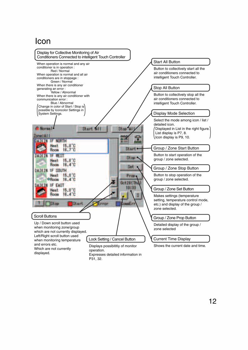
17
Monitoring Detailed Information
1819
20
Name : Group nameDetailed name : Detailed group nameType : Air-conditioner / ventilation / D3Dio / D3DiD3 Address : 1:1-00 to 1:4-15When DIII-NET Plus adapter is enabled: 1:1-00 to 2:4-15
Schedule Setup : Enabled or disabledHeating Optimization : Enabled or disabledTemperature Limit : Enabled or disabledChange Over Settings : Enabled or disabledSIv R / C : Parent or childCool / Heat Option
: Presence / Absence / Under SelectionOu / Unit Addr : Outside unit addressErr Code : 2-digit error code in case of error occurenceErr Unit No
: [–] for no error or unit number for error
5. Push [Prop] button 17 .The following maintenance data is displayed on the Detailed Information Screen Screen 5.Note that screens in the left-hand column are examples for group selection.
6. Push [Abnormal history] button 18 to display the Abnormal History Screen (Screen 6).
[For group selection]
Name : Zone nameDetailed name : Detailed zone nameStart1By1 : Enabled or disabledNb of Regist Grp : Number of groups registered in a zone Schedule Setup : Enabled or disabled
Name : group nameDetailed name : Detailed group nameError log : • Time : Error occurrence time • Err Code : 2-digit error code • Err Code No : Unit number
The following data is displayed on the Abnormal History.
[For zone selection]
[For group selection]
Name : group nameError log : • Time : Error occurrence time • Name : Error occurrence group name • Err Code : 2-digit error code • Err Code No : Unit number
Top 10 error logs are displayed, assigning the highest priority to the time of the latest error.
∗ When the same error recurs, the error time is renewed.
Check for display data and push [Close] button 20 to return to the detailed information screen Screen 5. To return to the Monitoring Screen Screen 4, push [Close] button 19 on that screen.
[For zone selection]

30
Screen 1 Monitoring (Icon)
Screen 2 Set
Screen 3 Advanced Operation
3
Monitoring Detailed Information
1
4
5
6
10
7
8
9
2
Monitor Ventilation Status of a zone or group in DetailWhen monitoring the operation status in detail, you may choose any of three display types, icon, detailed icon and list.
You may monitor the details of the operation status in units of zones or groups.
The following describes in order the contents of display data on Screen 2.The grayed characters 4 and 5 indicate the current status of the selected zone or group.The following data is displayed on the screen of the left-hand column. Ventilation mode : Heat ExchangeVentilation volume : Strong (Fresh up)
The following describes in order the contents of display data on the Advanced Operation screen Screen 3.
∗ Display data on Screens 2 and 3 is updated each time the respective screens are displayed. Once these screens are displayed, data is not updated unless they are closed and opened again.
1. Select either Zone or Group by pushing the button 1 . Note that screens in the left-hand column are examples for group lection.
Push [Set] button 2 to display the Operation Screen Screen 2.
2.
Push the [Advanced Operation] button 6 to display the Advanced Operation screen Screen 3.To return to the Monitoring Screen Screen 1, push [Cancel] button 10 .
7 displays the settings made for start- or stop-related remote control operations.Prohibited, Stop Only or Permitted is displayed.
8 displays a filter sign.ON or OFF is displayed.
3.
Check for display data and push [Cancel] button 9 .
4.

31
Screen 1 Monitoring (Icon)
Screen 2 Confirm
Screen 3 Passward to release lock
To set / release the lock of screen operation
1
2
3
4
5
6
Lock and Unlock Operations on the Screen
1.While the unlock button is displayed, push the button 1 to display the Confirmation Screen Screen 2.
Push Yes button 2 to return to the Monitoring Screen Screen 1 with the operations locked.Push No button not to lock the operations.
Unlock iconThis icon indicates that operations on the screen have been unlocked.
Lock iconThis icon indicates that operations on the screen have been locked. In this state, you cannot manipulate the air-conditioner or the system.
2.
[Lock method]
[Lock method]
3.While the lock icon is displayed, push the button 1 , Air-conditioner Operation button or System Operation button to display the Password to release lock Screen Screen 3.
4.Enter the password assigned for unlock password protection on P57.
3 : Toggle button for switching uppercase letters to lowercase letters
4 : Correction button for characters entered by hitting the incorrect keys.
When deleting one or more incorrect characters just immediate before the cursor, you must push this button as many times as necessary.
5 : Button for moving the cursor.After entering the password, push OK button 6 .
To cancel the entered password, push Cancel button and return to the Monitoring Screen Screen 1.
[Unlock method]
You may use a password to lock and unlock operations on the screen.To make this lock / unlock setting, you have to assign an unlock password on P57 beforehand. The key mark in the following figure does not appear unless this setting is made.

32
System Setup Menu
The System Setup menu includes the following items:
Operation(Reference)
System Setup Menu Item
Description
You can set passwords to restrict persons responsible for control operations.1. Assigning administrator passwords
You may assign administrator passwords to restrict system menu operations.2. Assigning unlock passwords
You may assign unlock passwords to restrict air-conditioner and system menu operations.When both passwords have been assigned, you have to reset them twice to resume the system menu operations.
Notes : When you forget the assigned passwords, you cannot perform any system operations. Don’t forget the passwords.When you don’t remember them, contact a dealer in your area.
Setting a Password
System menu : • Password Setup • Time setup • Backlight Setup • Zone / Group list • Locale setting • Network setting • Setting of icon color • License key input • History Display • Touch Panel Calibration • Version Information
Adjust the system clock (year, month, day, hour, minute and second).The clock is used for scheduled operation, saving history, power distribution (optional) and demand operation (optional).Note : Adjusting the clock may affect scheduled operation, power distribution
or demand operation.For the details of the influence, see the following. For power distribution and demand operation, see the respective instruction manual as well.
[Influence of changing the clock setting on scheduled operation] • The operation scheduled to run at a time passed by advancing the clock is
not performed.Ex.: When an air conditioner is scheduled to start at 10:00 ( 1 ):
If the time is adjusted to 10:05 at 9:55, the scheduled operation ( 1 ) is not performed.
• The operation scheduled to run at a time reached again by turning back the clock is performed again.
Ex.: When an air conditioner is scheduled to start at 10:00 ( 1 ):If the time is adjusted to 9:55 at 10:05, the scheduled operation ( 1 ) is performed again at 10:00.
Time Setup
The following table describes the items mentioned above.
See page
57
See page
58
Atm Control : • Schedule Setup • Change Over Settings • Temperature Limit Settings • Heating Optimization Settings • Setting of E-mail • Simple linkage Setup
33
Operation (Reference)
System Setup Menu Item
Description
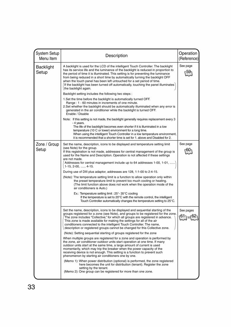
A backlight is used for the LCD of the intelligent Touch Controller. The backlight has its service life and the luminance of the backlight is reduced in proportion to the period of time it is illuminated. This setting is for preventing the luminance from being reduced in a short time by automatically turning the backlight OFF when the touch panel has been left untouched for a set period of time.If the backlight has been turned off automatically, touching the panel illuminates the backlight again.
Backlight setting includes the following two steps :
1.Set the time before the backlight is automatically turned OFF.Range : 1 - 60 minutes in increments of one minute.
2.Set whether the backlight should be automatically illuminated when any error is generated in the air conditioner while the backlight is turned OFF.Enable / Disable
Note: If this setting is not made, the backlight generally requires replacement every 3 - 4 years.The life of the backlight becomes even shorter if it is illuminated in a low temperature (10 C or lower) environment for a long time.When using the intelligent Touch Controller in a low temperature environment, it is recommended that a shorter time is set for 1. above and Disabled for 2.
Backlight Setup
Set the name, description, icons to be displayed and temperature setting limit (see Note) for the group.If this registration is not made, addresses for central management of the group is used for the Name and Description. Operation is not affected if these settings are not made.Addresses for central management include up to 64 addresses 1-00, 1-01, ...... 1-15, 2-00, ...... 4-15.
During use of DIII plus adaptor, addresses are 128, 1:1-00 to 2:4-15.
(Note): The temperature setting limit is a function to allow operation only within the preset temperature limit to prevent too much cooling or heating.(The limit function above does not work when the operation mode of the air conditioners is Auto.)
Ex.: Temperature setting limit : 25°- 35°C coolingIf the temperature is set to 20°C with the remote control, the intelligent Touch Controller automatically changes the temperature setting to 25°C.
Zone / Group Setup
Set the name, description, icons to be displayed and sequential starting of the groups registered for a zone (see Note), and groups to be registered for the zone.The zone includes “Collective,” for which all groups are registered in advance. This zone is made available for making the settings for all of the air conditioners connected to the intelligent Touch Controller. The name, description or registered groups cannot be changed for this Collective zone.
(Note): Setting sequential starting of groups registered for the zone
When multiple groups are registered for a zone and operation is performed by the zone, air conditioner outdoor units start operation at one time. If many outdoor units start at the same time, a large amount of current is used momentarily, which may trip the breaker when the power capacity of the receiving device is not enough. This setting is a function to prevent such phenomenon by starting air conditioners one by one.
(Memo 1): When power distribution (optional) is performed, the zone registered here becomes the unit for distribution (tenant). Register the zone setting by the tenant.
(Memo 2): One group can be registered for more than one zone.
See page
59
61 62to
See page
60
See pages

34
Operation (Reference)
System Setup Menu Item
Description
This menu permits you to select a language from the list displayed on the Intelligent Touch Controller.
By setting locale, you can display data in the selected language on the Intelligent Touch Controller.
Locale Setting
This menu permits you to set an IP address for the Intelligent Touch Controller.
(Remarks): When using a Web function (option), you have to set the IP address, subnet mask, etc. according to the environmental requirements of your system.
Network Setting
This menu permits you to change the icon colors on the Intelligent Touch Controller.Icons on the monitoring screen are displayed in the colors set on this menu.
Icon Color Setting
You have to input the license key to use various options of the Intelligent Touch Controller.If necessary, you can check the current license or add the new license.This setting is usually done by sales engineer of our company.
Input License Key
See page
62
See page
63
64
See page
65
See page
35
System SetupMenu Item
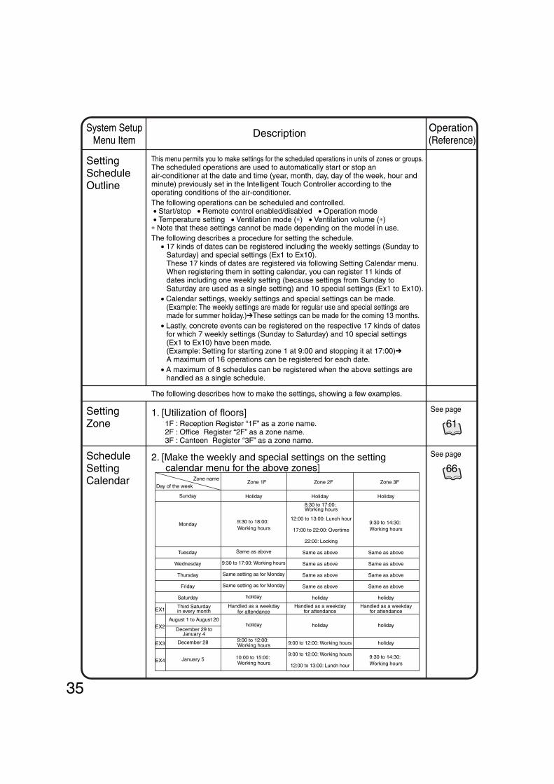
This menu permits you to make settings for the scheduled operations in units of zones or groups.The scheduled operations are used to automatically start or stop an air-conditioner at the date and time (year, month, day, day of the week, hour and minute) previously set in the Intelligent Touch Controller according to the operating conditions of the air-conditioner.The following operations can be scheduled and controlled. • Start/stop • Remote control enabled/disabled • Operation mode • Temperature setting • Ventilation mode (∗) • Ventilation volume (∗)∗ Note that these settings cannot be made depending on the model in use.The following describes a procedure for setting the schedule.
• 17 kinds of dates can be registered including the weekly settings (Sunday to Saturday) and special settings (Ex1 to Ex10).These 17 kinds of dates are registered via following Setting Calendar menu.When registering them in setting calendar, you can register 11 kinds of dates including one weekly setting (because settings from Sunday to Saturday are used as a single setting) and 10 special settings (Ex1 to Ex10).
• Calendar settings, weekly settings and special settings can be made.(Example: The weekly settings are made for regular use and special settings are made for summer holiday.)➔These settings can be made for the coming 13 months.
• Lastly, concrete events can be registered on the respective 17 kinds of dates for which 7 weekly settings (Sunday to Saturday) and 10 special settings (Ex1 to Ex10) have been made.(Example: Setting for starting zone 1 at 9:00 and stopping it at 17:00)➔A maximum of 16 operations can be registered for each date.
• A maximum of 8 schedules can be registered when the above settings are handled as a single schedule.
The following describes how to make the settings, showing a few examples.
1. [Utilization of floors] 1F : Reception Register “1F” as a zone name. 2F : Office Register “2F” as a zone name. 3F : Canteen Register “3F” as a zone name.
2. [Make the weekly and special settings on the setting calendar menu for the above zones]
Setting Schedule Outline
Setting Zone
Schedule Setting Calendar
61
See page
66
See page
Day of the week
EX1
EX2
EX3
EX4
Zone 1F Zone 2F Zone 3FZone name
Sunday
Monday
Tuesday
Wednesday
Thursday
Friday
Saturday
Third Saturday in every month
August 1 to August 20
December 29 to January 4
December 28
January 5
Holiday
9:30 to 18:00: Working hours
Same as above
9:30 to 17:00: Working hours
Same setting as for Monday
Same setting as for Monday
holiday
Handled as a weekday for attendance
holiday
9:00 to 12:00: Working hours
10:00 to 15:00: Working hours
Holiday
8:30 to 17:00: Working hours
12:00 to 13:00: Lunch hour
17:00 to 22:00: Overtime
22:00: Locking
Same as above
Same as above
Same as above
Same as above
holiday
Handled as a weekday for attendance
holiday
9:00 to 12:00: Working hours
9:00 to 12:00: Working hours
12:00 to 13:00: Lunch hour
Holiday
9:30 to 14:30: Working hours
Same as above
Same as above
Same as above
Same as above
holiday
Handled as a weekday for attendance
holiday
holiday
9:30 to 14:30: Working hours
Operation (Reference)
Description

36
Change Schedule Name
Setting Scheduled Event
Other Schedule Functions
67 69See pages
to
71 72See pages
to
70See page
70See page
70See page
7. [Convenient functions for setting a schedule]
Enable or disable a schedule.
6. [Enable or disable a schedule.]This function finally enables you to decide whether to enable or disable the setting made.
Change Special Date Name
5. [Change a special day name.]This function enables you to change the existing special holiday name to an easy-to-understand holiday name.
4. [Change a schedule name.]This function enables you to change the existing schedule name to an easy-to-understand schedule name.
3. [Set events for zone 2F.](Note) The following lists the events for reference.
Change the settings according to the actual use conditions.
System SetupMenu Item
Setting events for Monday to Friday
Setting events for Saturday and Sunday
Setting events for Ex1 (Third Saturday in every month)
Setting events for Ex2 (Summer holiday, etc.)
Setting events for Ex3 (December 28)
Setting events for Ex3 (December 28)
∗ The term “Disabled” means that the setting is not changed
Time 8:3012:0013:0017:0022:00
Target zoneZone 2FZone 2FZone 2FZone 2FZone 2F
Start/stopStartstopStart
Disabledstop
Setting temperatureDisabledDisabledDisabledDisabledDisabled
Remote control codeAssign priority to key pushed later
DisabledAssign priority to key pushed laterOnly stop operation permittedRemote control operation prohibited
Operation modeDisabledDisabledDisabledDisabledDisabled
Time
12:00
17:00
Target zone
Zone 2F
Zone 2F
Start/stop
Start
stop
Setting temperature
25ºC
Disabled
Remote control codeAssign priority to key pushed laterTemperature setting prohibitedOperation mode prohibitedOnly stop operation permitted
Operation mode
Heating
Disabled
Time
10:00
12:00
13:00
15:00
Target zone
Zone 2F
Zone 2F
Zone 2F
Zone 2F
Start/stop
Start
stop
Start
stop
Setting temperature
25ºC
Disabled
25ºC
Disabled
Remote control codeAssign priority to key pushed laterTemperature setting prohibitedOperation mode prohibitedOnly stop operation permittedAssign priority to key pushed laterTemperature setting prohibitedOperation mode prohibitedOnly stop operation permitted
Operation mode
Heating
Disabled
Disabled
Disabled
Time 8:3012:00
Target zoneZone 2FZone 2F
Start/stopStartstop
Setting temperatureDisabledDisabled
Remote control codeAssign priority to key pushed laterRemote control operation prohibited
Operation modeDisabledDisabled
Time 9:0017:00
Target zoneZone 2FZone 2F
Start/stopDisabled
stop
Setting temperatureDisabledDisabled
Remote control codeAssign priority to key pushed laterRemote control operation prohibited
Operation modeDisabledDisabled
Operation (Reference)
Description
37
Operation (Reference)
System Setup Menu Item
Description
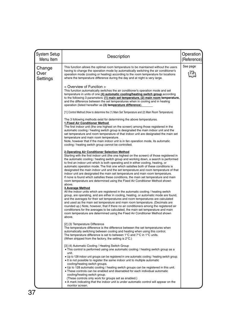
This function allows the optimal room temperature to be maintained without the users having to change the operation mode by automatically switching the air conditioner’s operation mode (cooling or heating) according to the room temperature for locations where the temperature difference during the day and at night is very large.
< Overview of Function >This function automatically switches the air conditioner’s operation mode and set temperature in units of one (4) automatic cooling/heating switch group according to the following 3 parameters: (1) main set temperature, (2) main room temperature, and the difference between the set temperatures when in cooling and in heating operation (listed hereafter as (3) temperature difference).
[1] Control Method (How to determine the (1) Main Set Temperature and (2) Main Room Temperature)
The 3 following methods exist for determining the above temperatures.1.Fixed Air Conditioner MethodThe first indoor unit (the one highest on the screen) among those registered in the automatic cooling / heating switch group is designated the main indoor unit and the set temperature and room temperature of that indoor unit are designated the main set temperature and main room temperature.Note, however that if the main indoor unit is in fan operation mode, its automatic cooling / heating switch group cannot be controlled.
2.Operating Air Conditioner Selection MethodStarting with the first indoor unit (the one highest on the screen) of those registered in the automatic cooling / heating switch group and working down, a search is performed to find an indoor unit which is both operating and in either cooling, heating, or automatic operation mode. The first one which satisfies both of these conditions is designated the main indoor unit and the set temperature and room temperature of that indoor unit are designated the main set temperature and main room temperature.If none is found which satisfies these conditions, the main set temperature and main room temperature are determined using the Fixed Air Conditioner Method shown above.3.Average MethodAll the indoor units which are registered in the automatic cooling / heating switch group, are operating, and are either in cooling, heating, or automatic mode are found, and the averages for their set temperatures and room temperatures are calculated and used as the main set temperature and main room temperature. (Decimals are rounded up.) Note, however, that if there no air conditioners among the registered air conditioners for the averages to be calculated, the main set temperature and main room temperature are determined using the Fixed Air Conditioner Method shown above.
[2] (3) Temperature DifferenceThe temperature difference is the difference between the set temperatures when automatically switching between cooling and heating when using this control.The temperature difference is set to between 1°C and 7°C in 1°C units.(When shipped from the factory, the setting is 2°C.)
[3] (4) Automatic Cooling / Heating Switch Group • This control is performed using one automatic cooling / heating switch group as a
unit. • Up to 128 indoor unit groups can be registered in one automatic cooling / heating switch group. • It is not possible to register the same indoor unit to multiple automatic
cooling/heating switch groups. • Up to 128 automatic cooling / heating switch groups can be registered in this unit. • These controls can be enabled and disenabled for each individual automatic
cooling/heating switch group. (These controls only work for groups set as enabled.) • A mark indicating that the indoor unit is under automatic control will appear on the
monitor screen.
Change Over Settings
73
See page

38
Operation (Reference)
System Setup Menu Item
Description
Change Over Settings
< Control Implementation Conditions > The relationship between the main room temperature, the main set temperature,
and the operation mode is described below, with examples. (Two examples are given, as the operation differs for temperature differences 2°C
and below and 3°C and above.) The controls are implemented when the control conditions are satisfied, every 5
minutes from the time the power is turned on. < Implementation conditions when the temperature difference is 2°C or lower.> (The figure below is for a temperature difference of 1°C)
Main heating set temperature(Example : 26°C)
Temperature
Main cooling set temperature(Example : 27°C)
Heating mode Heating modeTime
Cooling mode
Main room temperature
Main heating set temperature – 1°C
Main cooling set temperature + 1°C
1
2
1 Conditions for switching from heating to cooling : Main room temperature > main set temperature + temperature difference + 1°C (Example : 28.1°C > 26°C + 1°C + 1°C) 2 Conditions for switching from cooling to heating : Main room temperature < main set temperature – temperature difference – 1°C (Example : 24.9°C < 27°C – 1°C – 1°C)
1 Conditions for switching from heating to cooling : Main room temperature > main set temperature + temperature difference (Example : 27.1°C > 24°C + 3°C) 2 Conditions for switching from cooling to heating : Main room temperature < main set temperature - temperature difference (Example : 23.9°C < 27°C – 3°C)
<Implementation conditions when the temperature difference is 3°C or higher.>(The figure below is for a temperature difference of 3°C)
Main heating set temperature(Example : 24°C)
Temperature
Main cooling set temperature(Example : 27°C)
Time
Main room temperature
1
2
∗ See the next page for a detailed description of the instructions to the air conditioner.
Heating mode Cooling mode Heating mode
Temperature difference
Shift up from heating to cooling switch set temperature
Shift down from cooling to heating switch set temperature.
Shift up from heating to cooling switch set temperature
Temperature difference
73
See page
Shift down from cooling to heating switch set temperature.

39
Operation (Reference)
System Setup Menu Item
Description
Change Over Settings
The control instruction is sent to the indoor units registered in the automatic cooling / heating switch group when the control implementation conditions shown on the previous page are satisfied. The actual control instructions sent differ according to the control method setting (fixed air conditioner / operating air conditioner selection / average) and the satisfied conditions (switch from cooling to heating, etc.). The control instructions for each situation are shown below.
<Instructions sent to indoor units when control is implemented>1.Fixed air conditioner/operating air conditioner selection methods
The control instructions are determined by the operation mode of the main indoor unit and the main set temperature. Instructions regarding the operation mode and the set temperature, shown below, are sent to all the indoor units registered in the group once all the control implementation conditions on the previous page are satisfied.
For this control, when the operation mode of the main indoor unit is automatic, whether it is automatic cooling mode or automatic heating mode is checked when judging the control conditions. Once the instructions have been determined, either a cooling or a heating instruction is sent to indoor units in automatic operation mode.(They switch from automatic to cooling or heating.)
2. Average Method
Unlike the fixed air conditioner and operating air conditioner selection methods, the set temperature is decided based on considerations of the current set temperature for each individual unit, without sending the same instruction based on the main indoor unit to all the air conditioners. When implementing the control, the following operation modes and set temperature instructions are executed.
Operation mode Set temperature
cooling main unit setting temperature+temperature difference
cooling main unit setting temperature
Operation mode Set temperature
heating main unit setting temperature–temperature difference
heating main unit setting temperature
Operation mode Set temperature
cooling Current set temperature+temperature difference
No instruction No instruction
Other than the above cooling main unit setting temperature+temperature difference
Operation mode Set temperature
heating Current set temperature-temperature difference
No instruction No instruction
Other than the above cooling main unit setting temperature–temperature difference
When conditions are met for switching from heating to cooling
Instructions to indoor units registered in the automatic cooling / heating switch group
Operation mode of the main indoor unit
When conditions are met for switching from cooling to heating
Instructions to indoor units registered in the automatic cooling / heating switch group
Operation mode of the main indoor unit
When conditions are met for switching from heating to cooling
Current indoor unit operation mode
When conditions are met for switching from cooling to heating
Instructions to indoor units registered in the automatic cooling / heating switch group
Current indoor unit operation mode
Instructions to indoor units registered in the automatic cooling / heating switch group
Heating / Automatic heatingCooling / Automatic cooling
Heating / Automatic heatingCooling / Automatic cooling
Heating / Automatic heatingCooling / Automatic cooling
Heating / Automatic heatingCooling / Automatic cooling
73
See page

40
Operation (Reference)
System Setup Menu Item
Description
Change Over Settings
<Precautions when using this control>1.Do not use the set temperature restriction function in indoor units which are subject
to control.If it is used, operation modes will be switched and the set temperature will be changed repeatedly, possibly causing the air conditioners to break down.
(See P44 for how to set the set temperature restriction function.)
2.The following will happen if a communication error (the icon on the screen is blue) occurs in the air conditioner being controlled.
2-1.Fixed air conditionerIf the main unit experiences a communication error, the automatic cooling / heating switch group control will not happen.
2-2.Operating Air Conditioner Selection MethodRemove the air conditioner experiencing the communication error from selection as the main unit, and select an air conditioner with normal communication.
2-3.Average MethodRemove the air conditioner experiencing the communication error from the calculation for the average, and only use air conditioners with normal communication for calculating the average.
3.Control which matches the main unit’s operation mode(Control for when the operation mode of the main unit does not represent the automatic cooling / heating switch group.)It is possible that only the operation mode for the main unit is changed when control using this function is done based on the main group unit (when the control method is fixed air conditioner or operating air conditioner). The following control is performed because it is possible that the operation mode of air conditioners other than the main unit in the group might be in violation of the purpose of control and not automatically switch if the conditions for implementing control using this function are not satisfied.
[Example] Heating Mode-Matched ControlWhen the main unit is already operating in heating mode, whether or not the conditions for implementing a switch from cooling to heating (main room temperature < main set temperature – temperature difference) depends on the state (environment) of the main unit. (If only the main unit is in heating operation, it is possible that the room temperature might not rise because of the indoor units other than the main unit which are in cooling operation, and the above control conditions might not be satisfied.)Therefore, only when control is performed based on the main group unit is the control below performed depending on the operation mode of the main group unit.
Caution
Cooling Mode-Matched Control
Operation mode Set temperature
Operation mode Cooling / Automatic cooling
Temperature
Heating Mode-Matched Control
Operation mode Set temperature
Operation mode Heating / Automatic heating
Temperature
State of main unit (control conditions)
Heating main set temperature
State of main unit (control conditions)
Cooling main set temperature
Instructions to indoor units registered in the automatic cooling / heating switch group
Instructions to indoor units registered in the automatic cooling / heating switch group
Main room temperature < main set temperature
Main room temperature < main set temperature
73
See page

41
Operation (Reference)
System Setup Menu Item
Description
Change Over Settings
4.Because this control automatically switches the operation mode, if the air conditioner is not a cooling / heating free unit, always register indoor units which have the right to select cooling or heating for the same cooling system to the same automatic cooling / heating switch group, when controlling indoor units which do not have such rights.
Unexpected things may happen if control is done using the following incorrect automatic cooling / heating switch group settings.
If indoor units (address 1-02) which do not have the right to select cooling or heating for the same cooling system are not registered to the same automatic cooling / heating switch group, address 1-02 will behave in the following way.
[Actions related to operation mode]If the room temperature of Group 1 rises, group 1 will switch to cooling as per this control and the set temperature will become 25°C (if the temperature difference is 5°C).When this happens, the set temperature of the indoor unit at 1-02 will continue at 23°C although only the operation mode will change to cooling, i.e. in a different operation mode from the other indoor units in Group 2.→The operation mode will be determined by Group 1.
[Actions regarding set temperature]If the room temperature of Group 2 rises, group 2 will switch to cooling as per this control and the set temperature will become 28°C (if the temperature difference is 5°C).When this happens, the operation mode of the indoor unit at 1-02 will continue in heating and only the set temperature will change to 28°C, i.e. in a different operation mode from the other indoor units in Group 2.→The set temperature will be determined by Group 2.
1-00 1-01 1-02
1-03 1-04 1-05
Operation mode : Heating, set temperature 20°C
Operation mode : Heating, set temperature 23°C
73
See page
Outdoor unit
Outdoor unit
Automatic cooling / heating switch group 1
Has right to select cooling or heating
Does not have right to select cooling or heating
Does not have right to select cooling or heating
Automatic cooling / heating switch group 2
Does not have right to select cooling or heating
Has right to select cooling or heating
Does not have right to select cooling or heating
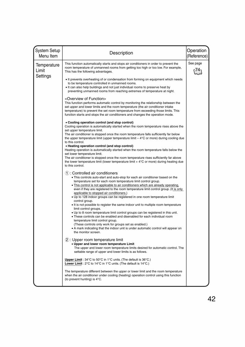
42
Operation (Reference)
System Setup Menu Item
Description
Temperature Limit Settings
This function automatically starts and stops air conditioners in order to prevent the room temperature of unmanned rooms from getting too high or too low. For example, This has the following advantages.
• It prevents overheating of or condensation from forming on equipment which needs to be temperature controlled in unmanned rooms.
• It can also help buildings and not just individual rooms to preserve heat by preventing unmanned rooms from reaching extremes of temperature at night.
<Overview of Function>This function performs automatic control by monitoring the relationship between the set upper and lower limits and the room temperature (the air conditioner intake temperature) to prevent the set room temperature from exceeding those limits. This function starts and stops the air conditioners and changes the operation mode.
• Cooling operation control (and stop control)Cooling operation is automatically started when the room temperature rises above the set upper temperature limit.The air conditioner is stopped once the room temperature falls sufficiently far below the upper temperature limit (upper temperature limit – 4°C or more) during cooling due to this control. • Heating operation control (and stop control)Heating operation is automatically started when the room temperature falls below the set lower temperature limit.The air conditioner is stopped once the room temperature rises sufficiently far above the lower temperature limit (lower temperature limit + 4°C or more) during heating due to this control.
1 : Controlled air conditioners• This controls auto-start and auto-stop for each air conditioner based on the
temperature set for each room temperature limit control group.• This control is not applicable to air conditioners which are already operating,
even if they are registered to the room temperature limit control group. (It is only applicable to stopped air conditioners.)
• Up to 128 indoor groups can be registered in one room temperature limit control group.
• It is not possible to register the same indoor unit to multiple room temperature limit control groups.
• Up to 8 room temperature limit control groups can be registered in this unit.• These controls can be enabled and disenabled for each individual room
temperature limit control group. (These controls only work for groups set as enabled.)• A mark indicating that the indoor unit is under automatic control will appear on
the monitor screen.
2 : Upper room temperature limit• Upper and lower room temperature Limit
The upper and lower room temperature limits desired for automatic control. The settable range of upper and lower limits is as follows.
Upper Limit : 34°C to 50°C in 1°C units. (The default is 36°C.)Lower Limit : 2°C to 14°C in 1°C units. (The default is 14°C.)
The temperature different between the upper or lower limit and the room temperature when the air conditioner under cooling (heating) operation control using this function (to prevent hunting) is 4°C.
74
See page

43
Operation (Reference)
System Setup Menu Item
Description
Temperature Limit Settings
3 : Control Implementation ConditionsThe relationship between room temperature, upper / lower limit, and operation mode is shown below.The controls are implemented when the control conditions are satisfied, every 5 minutes from the time the power is turned on.
This function performs stop control for cooling / heating operation and other operation controls to prevent excessive increase or decrease of the room temperature. The set values of room temperature upper / lower limit control group are used for the upper / lower limit values and other factors of this control.This control is not performed for the group of air conditioners to which this control is set invalid. The set temperatures of the air conditioners are not changed by this control.
1 Start condition of cooling operation :Cooling operation is controlled when the room temperature is higher than the upper limit of room temperature and the unit is stopped.
2 Start condition of heating operation :Heating operation is controlled when the room temperature is lower than the lower limit of room temperature and the unit is stopped.
3 Stop condition :The air conditioners under cooling / heating control by this function stop when any of the following conditions are met.
• During cooling operation“Room temperature is lower than the upper limit of room temperature – 4°C” or “Room temperature is lower than the cooling set temperature”
• During heating operation“Room temperature is higher than the lower limit of room temperature + 4°C” or “Room temperature is higher than the heating set temperature”
Room temperature
Time
Lower limit
Upper limit
Lower limit + 4°C
Upper limit – 4°C
Heating operation control
Room temperature is controlled into
this range.
Cooling operation control
Heating operationAir conditioner stop
Cooling operation
Air conditioner stop
74
See page
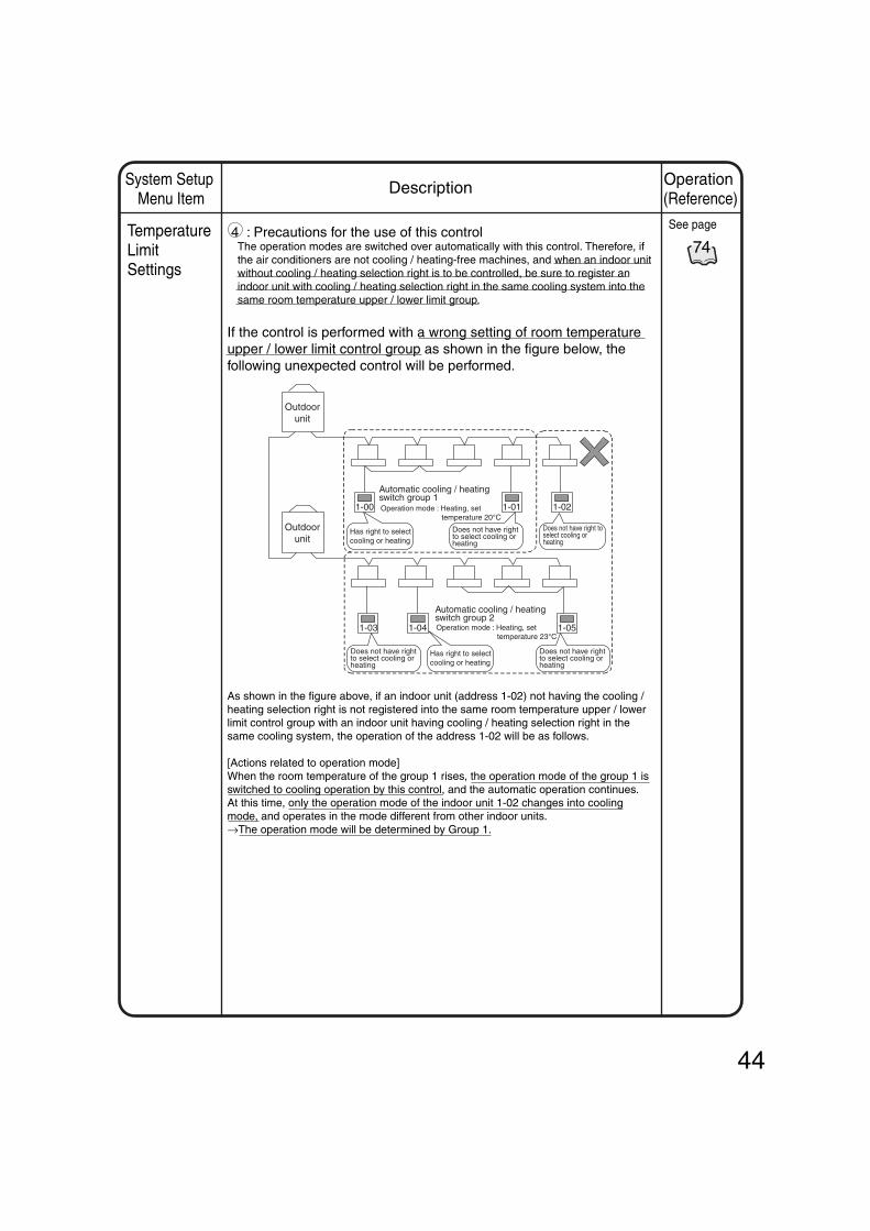
44
Operation (Reference)
System Setup Menu Item
Description
Temperature Limit Settings
4 : Precautions for the use of this controlThe operation modes are switched over automatically with this control. Therefore, if the air conditioners are not cooling / heating-free machines, and when an indoor unit without cooling / heating selection right is to be controlled, be sure to register an indoor unit with cooling / heating selection right in the same cooling system into the same room temperature upper / lower limit group.
If the control is performed with a wrong setting of room temperature upper / lower limit control group as shown in the figure below, the following unexpected control will be performed.
As shown in the figure above, if an indoor unit (address 1-02) not having the cooling / heating selection right is not registered into the same room temperature upper / lower limit control group with an indoor unit having cooling / heating selection right in the same cooling system, the operation of the address 1-02 will be as follows.
[Actions related to operation mode]When the room temperature of the group 1 rises, the operation mode of the group 1 is switched to cooling operation by this control, and the automatic operation continues.At this time, only the operation mode of the indoor unit 1-02 changes into cooling mode, and operates in the mode different from other indoor units.→The operation mode will be determined by Group 1.
1-00 1-01 1-02
1-03 1-04 1-05
Operation mode : Heating, set temperature 20°C
Operation mode : Heating, set temperature 23°C
Outdoor unit
Outdoor unit
Automatic cooling / heating switch group 1
Has right to select cooling or heating
Has right to select cooling or heating
Automatic cooling / heating switch group 2
Does not have right to select cooling or heating
Does not have right to select cooling or heating
Does not have right to select cooling or heating
Does not have right to select cooling or heating
74
See page

45
Operation (Reference)
System Setup Menu Item
Description
Heating Optimization Setting
With the air conditioners made by Daikin (Buil-Mul or Building multi indoor unit), when the thermo-switch is turned off (the compressor is off) during heating operation, the fan does not stop. (It continues to run at the minimum speed, or at the speed set in the heating mode.)Also, because a slight amount of coolant continues to circulate at this time, the room temperature may rise slightly by the fan operation described above.Therefore, this function starts / stops the air conditioner based on the room temperature (intake air temperature) and the set temperature during heating operation to prevent the temperature rise.
<Overview of Function>
• Operation interruption controlWhen the room temperature for the air conditioner in heating operation becomes higher than the set temperature + 1°C, the air conditioner is stopped. However, because the stop control (operation interruption) by this function is the optimum control for turning off of the thermo-switch during heating operation, the system regards this status as in operation, and the screen display on the unit remains “In-operation.”∗After the unit is interrupted by this function, it restarts when the specified conditions are met. Therefore the user’s explicit stop command is effective.
• Operation restart controlWhen the room temperature for the air conditioner under the stop control by this function (during heating operation interruption) becomes lower than the set temperature – 1°C, the air conditioner is restarted.
1 : Controlled air conditioners
• This control is performed for each individual air conditioner. This function can be set to enabled / disabled for each air conditioner.
• Only the air conditioners with this function set to enabled becomes the subject for the control.
• For the indoor units under this control, a mark showing the automatic control is displayed on the monitoring screen.
75
See page

46
2 : Control execution conditionThe relationship between room temperature, set temperature, and operation / stop status is shown in the figure below.The operation period of the control is every 5 minutes after the system power is turned on, and the operation is executed when the control conditions are met at each timing.
This function performs start / stop control based on the relationship between the set temperature and the room temperature (intake air temperature) of the air conditioner in heating operation. The control conditions are described below.
Operation interruption control in heating mode (Stop control)When the room temperature for the air conditioner in heating operation becomes higher than the set temperature + 1°C, the air conditioner is stopped. The stoppage (operation interruption) by this control is processed as “in-operation of the air conditioner” on the monitoring screen of the unit.
Operation restart control in heating mode (start control)When the room temperature for the air conditioner in interruption becomes lower than the set temperature – 1°C by this function, the air conditioner is restarted.
Enabled-to-disabled change over control (start control)When the setting of this function for the air conditioner is changed from enabled to disabled during operation interruption, the operation is restarted.
Operation mode change over control (Start control)When the operation mode of the air conditioner in interruption is changed by this function, the air conditioner is restarted.
3 : Precautions for the use of this control
1.The stoppage (operation interruption) by this control is processed as “in-operation of the air conditioner” on the monitoring screen of the unit. As a result, this status is indicated as “Stop” on the remote controller of the air conditioner, and as “In-operation” on the monitoring screen of the unit.
2.As explained above (item 1), because the display on the remote controller during operation interruption by this control is “Stop,” the user may not perform the stop operation even at the scheduled time of system stoppage, resulting in forget-to-stop error. Therefore, it is recommended that a measure against forget-to-stop error be executed by the scheduled control of the unit or other appropriate methods.
Temperature
Time
Set temperature-1°C
Heating set temperature
Set temperature+1°CRoom temperature
Fan stop
Operation restart
Interruption control
“Indoor unit room temperature/set temperature,” and “heating operation interruption control”
Operation (Reference)
System Setup Menu Item
Description
Heating Optimization Setting
75
See page

47
System SetupMenu Item
77 78
See pages
to
E-mail Setting* The e-mail
function is included in an option sold separately, where combined with the Web function.
Item
Validity/Invalidity of e-mail function
SMTPServer
Sending Conditions
DescriptionSetting of Invalidity does not allow sending e-mails.Specifies URL (IPaddress) of the SMTP server.Specifies a port number of the SMTP server.Whether to access in advance the POP server specified before sending mail.Specifies URL (IPaddress) of the POP server.Specifies a port number of the POP server.User ID used for POP authenticationPass word used for POP authenticationSpecifies destination groups to which an e-mail will be sent at a time of malfunction.Specifies a time interval to retry sending an e-mail when the malfunction has not been cleared. (setting range : 1-72 hours, steps : one hour)Specifies a string of characters displayed in the Subject column when the e-mail is received.Specifies e-mail addressesOmissible
SMTP Server Address
SMTP Server Port Number
Validity / Invalidity of [POP before SMTP] option
Setting itemswhen [POPbefore SMTP]is valid
Sent-to Groups
Sending Interval
ITC Identification Name
Mail Address 1, 2, 3
POP Sever Address
POP Server Port
Number
POP User ID
POP Password
Operation (Reference)
Description
This option is used to, when the Intelligent Touch Controller detects a malfunction in such as the air-conditioning unit (*1), send an e-mail containing the date, the error code and so on to the pre-registered administrators at three different addresses maximum. *1 : Where the malfunction refers a malfunction that occurs in the air- conditioning unit
or other facilities.When a communication error between the Intelligent Touch Controller and the
air-conditioning unit or other facilities occurs, no e-mail will be sent.If the warning of the air-conditioning unit occurred during a test run is defined to be
handled as a malfunction, the e-mail about such warning will be sent.
To use the e-mail function, the following equipment is required : SMTP (Simple Mail Transfer Protocol) servera server which can transfer the e-mails complying with RFC821 e-mail receiving terminal a terminal which can receive the e-mails complying with RFC822
The system configuration is drawn in the figure below :
Internet
In this setting procedure, the following items are set.
SMTP server
Intelligent Touch Controller
Ethernet (10BASE-T)
Send an e-mail when a malfunction occurs
e-mail receiving terminal

System SetupMenu Item
77 78
See pages
to
Operation (Reference)
Description
48
Timing of E-mail Sending Referring to the figure below, timing of sending e-mails is described. [Send when a malfunction occurs in the normal state]
If a malfunction occurs in the destination groups defined in the e-mail sending, wait three minutes from the malfunction ( 1 in the figure below) before sending an e-mail. * An e-mail will not be sent immediately after the first malfunction. During the waiting time of three minutes, if another malfunction occurs in different groups ( 2 or 3 in the figure below), one e-mail containing such multiple malfunctions will be sent.
[Resend after sending once] As shown in case of Group B, if the malfunction persists even after the sending time interval from the first mail sending has elapsed, another e-mail will be sent. In the group for which the e-mail has been sent, after recovering from the malfunction, if another malfunction occurs again ( 5 in the figure below), the latest malfunction will be sent after the sending time interval will have elapsed. During the sending time interval, if a new malfunction occurs ( 4 in the figure below), an e-mail will be sent after the sending time interval will have elapsed. When the sending time interval has elapsed, if no malfunction is found in the groups, the system will move from the resend state to the normal state.
* : The mark represents occurrence of a malfunction and the mark represents recovery from the malfunction.
Group B
Group D
Resend state
i
Figure : Timing of E-mail Sending
Group A
1
2
5
Group C
43
Normal state
Normal state
Sending time interval
Sending time interval
3 minutes from occurrence of the malfunction (wait for sending)
Send the malfunctions occurred in Group A, B, C
Send the malfunctions occurred in Group B, C, DGroup B : The malfunction
persists. Group C : The malfunction has
occurred again. Group D : Another malfunction
has occurred.
If no malfunction is found, the system will send no e-mail and go back to the normal state to start monitoring the air-conditioning unit.

49
System SetupMenu Item
77 78
See pages
to
• Contents of E-mail The contents of the e-mail to be sent is described below. When three or more events of malfunctions have been occurred concurrently, the latest two events are displayed in ascending order and the rest is represented just as the total number of such events.
• Operation when failing to send an e-mail When failing to send an e-mail, it will be resent three times at an interval of two minutes. Resending an e-mail will not be executed, however, in the following situations : • The POP sever returned an error of user authentication. • The SMTP server returned a reply of a permanent failure. • A test run mail was sent.
• E-mail outgoing history The history file can contain a maximum number of 300 events of successes / failures in sending e-mails. * For detailed information, refer to the history display of P76.
Operation (Reference)
Description
From : [email protected]
To : [email protected]
Subject : Fault occurs (DAIKIN Head Office)
04/02 14:11 Office A9
04/02 14:10 ConfRoom E0
Remaining mails : 1
Originating e-mail address
Destination e-mail address
Fixed string of charactersand controller name
Date of occurrence of the malfunction (month, day, hour, minute) in ascending order starting from the latest one, group name, error code
Number of the remaining malfunctions except two indicated above when three or more malfunctions exist

System SetupMenu Item
79 80
See pages
to
This menu is used to make settings of an interlock control function in units of zones or groups.
The simple interlock control is a function to automatically control groups or zones corresponding to a change of the operation states or the stop states in any groups.
The settings of the simple interlock control are described below. • The simple interlock can store a maximum number of 128 program registrations.
For each program, the following settings can be made :
• Interlock input pointThe target groups you want to monitor as the interlock input points(e.g. air-conditioning unit, Di unit*, Dio unit*, HRV) are registered.* : Monitoring is performed for the input states at the operation / stop connection point.
In one program, the maximum number of 128 groups can be registered.
• Interlock output"Select conditions of interlock input points", "Registration of control targets", and
"Settings of control details" are performed.
• "Select condition of interlock input points"The interlock control function is initiated when the groups specified as the interlock
input points indicate the operation states described below. Select from (1)-(5) to specify the condition. (The control function is actually initiated when the state of the input point has changed.)
(1) No detection : Detection of inputs is not performed. (The control function is not effective.)
(2) Any one or more of the groups ON :When any one or more of the groups registered as the input points turn on, the
control function is initiated. (3) All ON : When all of the registered groups as the input points turn on, the ?
control function is initiated. (4) Any one or more of the groups OFF :When any one or more of the groups registered as the input points turn off to stop,
the control function is initiated. (5) All OFF : When all of the registered groups as the input points turn off to ?
stop, the control function is initiated. *1 Selecting "Any one or more of the groups ON (or OFF)" while some interlock
input points are already ON (or OFF) will not initiate anew the interlock control function even when another interlock input point turns ON (or OFF). (Once the selected condition has become invalid and then, when the selected condition is satisfied again, the function can be initiated.)
*2 When a communication error occurs in any of the interlock input points, the condition will be checked only for the interlock input points in the normal communication state.
• "Registration of control targets"A single group or zone, which is to be controlled when the interlock condition is met,
is registered.* If the interlock condition has been met during a communication error in the control target,
the interlock control function will not be initiated even when the communication error is cleared.
• "Settings of control details"Details of the control operations for the target device where the interlock condition is
met are defined. The available control operations are described below. Multiple operations can be set at a time. (Ex. : Start Command and Change Temperature Setting)
• Start / Stop commands • Operation mode switching • Change temperature setting• Setting of permission / prohibition of hand-held remote controller operations
(Start / Stop, Temperature setting, Operation mode switching) • Ventilation mode switching (*)• Ventilation amount switching (*)* for HRV
For one interlock program, two interlock outputs at the maximum can be specified.
Operation (Reference)
Description
50
Simple Interlock Setting

51
System SetupMenu Item
79 80
See pages
to
Control operations when a communication error occursin the interlock input pointsExample 1) When a communication error occurs in any of the interlock input points,
the condition will be checked only for the interlock input points in the
Control operations when a communication error occurs in the control target equipment
Operation (Reference)
Description
1-00 1-01 1-02 1-03
1-00 1-01 1-02 1-03
1-00 1-01 1-02 1-03
(1)
(2)
(3)
(4)
(5)
1-00 1-01 1-02 1-03 1-10interlock input point
When "All ON" is selected, the state change shown in the left figure can initiate the interlock control function.
Example 2) Even if the interlock input point recovered from the communication error meets the specified condition, the interlock control function cannot be initiated.
When "Any one or more of the groups ON" is selected, the state change shown in the left figure cannot initiate the interlock control function.
Example 3) When a communication error occurs in an interlock input point and, consequently, the specified condition is met, the interlock control function cannot be initiated.
Even when "All OFF" is selected, the state change shown in the left figure cannot initiate the interlock control function.
The condition of interlock input points is not met.
Although the condition of interlock input points is met, the communication error in the control target will not allow initiating the interlock control function.
Even when the control target recovers from the communication error, the interlock control function is not initiated.
In this case, once the condition of interlock input points has become invalid and then, when the condition is satisfied again, the interlock control function can be initiated.
Condition of interlock input points :"All ON" is selected.
Control target equipment

System SetupMenu Item
79 80
See pages
to
In the following section, utilization of the simple interlock control function is described while giving some examples. Referring to the figure below, the setting examples of the simple interlock control program are provided.
[Example 1 of interlock control] When any of the air-conditioning units on the second floor (1-00, 1-01) start operating, HRV (1-02) will be started. When all of the air-conditioning units (1-00, 1-01) on the second floor stop, HRV (1-02) will be stopped.
[Example 2 of interlock control] When the key of the first floor (2-03)* is locked, the air-conditioning units ?(2-00 to 2-02) will be stopped and start/stop operations of the hand-held remote controller will be prohibited.
* : The mark shown in the figure below represents a key. In this example, locking the key to the Di unit allows a closing (ON) connection point to be connected.
• Before the interlock control is activated
• While the interlock control isactived
Operation (Reference)
Description
52
2-03(open)
Zone Name : Zone 1F
Zone Name : Zone 1F
2-03(closed)
(HRV)1-00 1-01 1-02
(HRV)1-00 1-01 1-02
2-00 2-01 2-02
2-00 2-01 2-02
Settings for performing the control operations described above
Air-conditioning unit (1-00) in operation Di unit (2-03) locked
Interlock
input point
1-00
1-01
2-03
Input Condition
Anyone or more
of the groups ON
All ON
Control Item
Start operation
• Stop• hand-held
remote controller• Prohibition of
start/stop
Interlock Output 1
Control Target
1-02
Zone 1F
Input Condition
All OFF
No detection
Control Item
Stop
–
Interlock Output 2
Control Target
1-02
–
Interlock Program Number
Program 1
(two interlock
operations)
Program 2
(one interlock
operations)
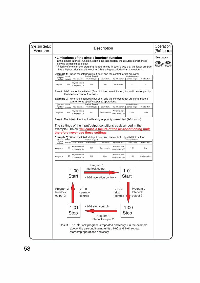
53
System SetupMenu Item
79 80
See pages
to
• Limitations of the simple interlock function In the simple interlock function, setting the inconsistent input/output conditions is allowed as described below. * Priority of the interlock programs is determined in such a way that the lower program
has a higher priority and the output 2 has a higher priority than the output 1.
Example 1) When the interlock input point and the control target are same
Result : 1-00 cannot be initiated. (Even if it has been initiated, it should be stopped by the interlock control function.)
Example 2) When the interlock input point and the control target are same but the control items specify opposite operations
Result : The interlock output 2 with a higher priority is executed. (1-01 stops.)
The settings of the input/output conditions as described in the example 3 below will cause a failure of the air-conditioning unit; therefore never use these settings.Example 3) When the interlock input point and the control output fall into a loop
Operation (Reference)
Description
Input Condition
Any one or more
of the groups ON
Control Item
Stop
Interlock Output 1
Control Target
1-00
Input Condition
No detection
Control Item
–
Interlock Output 2
Control Target
–
Input Condition
Any one or more
of the groups ON
Control Item
Start operation
Interlock Output 1
Control Target
1-01
Input Condition
Any one or more
of the groups OFF
Control Item
Stop
Interlock Output 2
Control Target
1-01
Input Condition
Any one or more
of the groups ON
Any one or more
of the groups ON
Control Item
Start operation
Stop
Interlock Output 1
Control Target
1-01
1-00
Input Condition
Any one or more
of the groups OFF
Any one or more
of the groups OFF
Control Item
Stop
Start operation
Interlock Output 2
Control Target
1-01
1-00
1-00Start
1-01Start
1-00Stop
1-01Stop
<1-01 operation control>
Program 1Interlock output 1
<1-01 stop control>
Program 1Interlock output 2
Result : The interlock program is repeated endlessly. ?In the example above, the air-conditioning units : 1-00 and 1-01 repeat start/stop operations endlessly.
Interlock Program Number
Program 1
Interlock
input point
1-00
Interlock Program Number
Program 1
Interlock
input point
1-00
Interlock Program Number
Program 1
Program 2
Interlock
input point
1-00
1-01
Program 2Interlock output 2
Program 2Interlock output 2
<1-00operation control>
<1-00stop control>

System SetupMenu Item
[Change the name of the simple interlock program] You can change the name of the simple interlock program to the understandable one.
[Determine the validity / invalidity of the simple interlock setting] Lastly, whether the simple interlock setting is valid or invalid can be specified. The program set to invalid will not run.
Operation (Reference)
Description
54
81
See page
81
See page
Simple Interlock Change Name
Simple Interlock Validity / Invalidity Setting

Operation (Reference)
System Setup Menu Item
Description
History Display
This menu should be displayed on the screen stored in the memory of intelligent Touch Controller and used to store data in memory card (customer-arranged).
Touch Panel Calibration
Menu for adjusting the positions of buttons on the touch panel used as the screen of the intelligent Touch Controller.
If a phenomenon such as “the intelligent Touch Controller does not recognize the pressing on the button shown on the screen” repeatedly occurs, use this menu to calibrate the touch panel.
Version information
This provides maintenance information. The menu shows the version number of the software for the intelligent Touch Controller currently used.
See page
76
77
82
See page
See page
55

1.Press the [S] button 1 on Screen 1 Monitoring.
2. Screen 2 System Setup Menu (see lower left) appears.If a password is set, the screen does not appear unless the password is entered.
3. Select an item from the System Setup Menu.
Click the item to be set 3 . and press the [Execute] button 4 .
The example on the left shows the appearance of the screen for password setup.
The following pages describe the System Setup operation in order.
3-2.
The setting screen selected appears.3-3.
Select an item from pull-down menu 2 . • System • Atm control
3-1.
When the setting has been made on the setting screen, press Exit (OK) or cancel.Detailed operation is described in the following items.
3-4.
Screen 2 reappears. The setting selected is complete.
3-5.
If another item is to be set, repeat the operation in 3-1 - 3-5.If there is no more item to be set, press the [Close] button 5 .Screen 1 Monitoring screen reappears.
3-6.
System Setup Menu OperationViewing the System Setup Menu Screen
Screen 1 Monitoring Screen
Screen 2 System Setup Menu
1
23
5
4
56
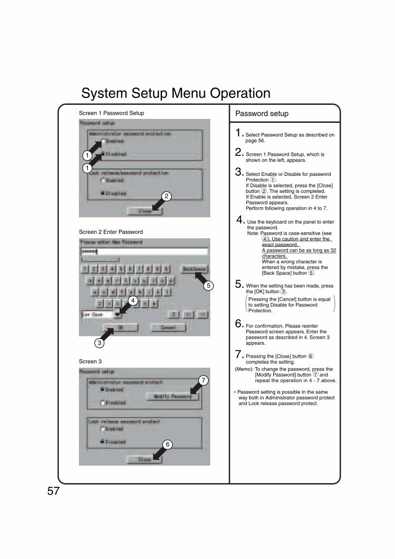
Screen 1 Password Setup
1. Select Password Setup as described on page 56.
2. Screen 1 Password Setup, which is shown on the left, appears.
3. Select Enable or Disable for password Protection 1 .If Disable is selected, press the [Close] button 2 . The setting is completed.If Enable is selected, Screen 2 Enter Password appears.Perform following operation in 4 to 7.
4. Use the keyboard on the panel to enter the password.Note: Password is case-sensitive (see
4 ). Use caution and enter the exact password.A password can be as long as 32 characters.When a wrong character is entered by mistake, press the [Back Space] button 5 .
5.
System Setup Menu Operation
Screen 2 Enter Password
6. For confirmation, Please reenter Password screen appears. Enter the password as described in 4. Screen 3 appears.
7. Pressing the [Close] button 6 completes the setting.
(Memo): To change the password, press the [Modify Password] button 7 and repeat the operation in 4 - 7 above.
∗ Password setting is possible in the same way both in Administrator password protect and Lock release password protect.
Screen 3
Password setup
1
3
1
2
4
5
7
6
Pressing the [Cancel] button is equal to setting Disable for Password Protection.
57
When the setting has been made, press the [OK] button 3 .

Screen 1 Time Setup
Screen 2
Screen 3 Confirmation
1. Select Time Setup as described on page 56.
2. Screen 1 Time Setup, which is shown on the left, appears.Press the [Modify] button 1 .Time setting dialog in Screen2 is displayed.
3. Press the number key button to set the year, month, day, hour, minute and second.
4.
5.
Time setup
3
1
2
4
See the Note on page 25. If changing the time setting causes no problem, press the [OK] button 4 . Time setup is complete.To cancel setting, press the [Cancel] button.
System Setup Menu Operation
58
When the setting has been made, press the [OK] button 3 .Screen 3 Confirmation appears.

System Setup Menu OperationScreen 1 Backlight Setup
4
1
3 3
1
2
1. Select Backlight Setup as described on page 56.
2. Screen 1 Backlight Setup, which is shown on the left, appears.
3. Press Enable or Disable for Backlight Auto Off 1 .If you select Disabled, go to step 6.
4. Press the [Modify] button 2 . Input dialog is displayed.Set the time for automatic OFF.
5. Set whether the backlight should be automatically turned ON when any error is generated in air conditioners by selecting Enable or Disable 3 .
6.
Backlight setup
Press the [OK] button 4 .To cancel the setting, press the [Cancel] button.
For longer service life of the backlight, select Enable whenever the backlight does not need to be illuminated all the time. The backlight once turned OFF is illuminated again when the panel is touched or automatically activated by any error generated in the air conditioner if Enable is selected for 5. Auto On Detect Err.
Caution
59

60
1.Select Group Setup as described on page 56.
2. Screen 1 Group [Setup], which is shown on the left, appears.
3. Select the group to be set with 1 .Press the [Setup] button 2 .Group setup in Screen 2 is displayed.
4. Press the [Modify] button 3 .Screen 2 Enter Group Name appears.Use the keyboard on the panel to enter the name in such a way that it is contained in the area 4 .If it is not contained in the area, reduce the number of characters and reenter.
5. Press the [Modify] button 10 and enter the name as shown in step 4 above.
7. Press the [Temp Limit] button 12 . Screen 4 Temp Limit appears. Select Enbled or Dlsabled 13 for Limits Setup for the group currently selected.If you select Yes, set the limits by press the [OK] button 15 . Press the [Modify] button 14 and set the restriction range.Screen 2 Group Setup reappears.
8. Select the position with the [Down] or [Up] button 17 for showing the group currently selected within the zone.
9.
6. Press the [▲] or [▼] button 11 to select an icon.The selection of icon does not affect the operation of the group.
Group setup
System Setup Menu OperationScreen 1 Group Setup
Screen 2 Group Setup
Screen 3 Enter Group Name
Screen 4 Temp Limit
1
3
10
14
11
12
1
17
18
2
16
4
5
13
15
7
69 8
6 : Button to select between uppercase and lowercase.
7 : Button to correct wrong entries made.
Pressing one time deletes one character leftward starting at the cursor.
8 : Button to move the cursor. 9 : Candidates for input are displayed.Words presumed to be input for Name
has already been involed.
When all entries have been made, press the [OK] button 5 .To cancel, press the [Cancel] button.Screen 2 Group Setup reappears.
Press the [OK] button 18 .To cancel the setting, press the [Cancel] button.
[How to use the keyboard]

1.Select Zone Setup as described on page 56.
2. Screen 1 Zone Setup, which is shown on the left, appears.
To add a zone, press the [Add] button 1 . A zone is added with the name Z-000.To modify the zone, select with 2 the zone to be modified.Press the Setup button. Zone setup inscreen2 is displayed.
3.
4. Press the [Modify] button 4 .Screen 3 Enter Group Name appears.Use the keyboard on the panel to enter the name in such a way that it is contained in the area 5 .If it is not contained in the area, reduce the number of characters and reenter.
5.Press the [Modify] button 11 and enter the name as shown in step 4 above.
6.Press the [▲] or [▼] button 12 to select an icon.The selection of icon does not affect the operation of the group.
7.For operation by the zone, to start the groups in the zone one by one rather than at one time, press the Enable button for Interval Start 13 . To start the groups at one time, press Disable.If you select Enable, press the [Modify] button 14 and set the interval time for group sequential start.
(Note) For the zone Collective, the factory setting is Enable for Interval Start and 2 (seconds) for Interval.
Zone setup
[How to use the keyboard] 7 : Button to select between
uppercase and lowercase. 8 : Button to correct wrong entries
made.Pressing one time deletes one
character leftward starting at the cursor.
9 : Button to move the cursor. 10 : Candidates for input are displayed.Words presumed to be input for Name
has already been involed.
When all entries have been made, press the [OK] button 6 .To cancel, press the Cancel button.Screen 2 Group Setup reappears.
Screen 1 Zone Setup
2
3
13
5
6
15
8
910
7
1
16
4
11
12
14
Screen 2 Zone Setup
Screen 3 Enter Group Name
System Setup Menu Operation
61

8.Set the groups to be registered for the zone currently selected.
To add a group to the zone, select the group to be added with 17 and press the [<<] button 18 .
To delete a group registered for a zone, select the group to be deleted with 19 and press the [>>] button 20
The [Up] or [Down] button 21 allows changing the order in display of groups in the zone currently selected on the Monitoring screen.
The group shown on the top is the representative unit for the zone.In the example of Screen 3 shown on the left, 1F Lobby is the representative unit for the zone 1F.
When all editing has been completed, press the [OK] button 22 .To cancel the setting, press the [Cancel] button.
Zone setup 2Screen 3 Registered Groups Edit
19 17
21
18
22
20
System Setup Menu Operation
1.Select “Locale Setting” according to the operating procedure shown in page 56.
2. Confirm that the Locale setting screen Screen 1 will be displayed in the left-hand column.
3. Select a language by pushing [<<], [>>] button 1 on the Locale setting screen.
(The details of settings remain unchanged.)
4. Select a language via the Language setting radio button 2 .
5. Last, push [OK] button 3 . To cancel the settings made, push [Cancel] button.
Locale SettingScreen 1 Locale setting
3
1 1
2
62
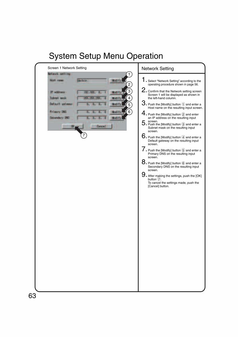
1.Select “Network Setting” according to the operating procedure shown in page 56.
2. Confirm that the Network setting screen Screen 1 will be displayed as shown in the left-hand column.
3. Push the [Modify] button 1 and enter a Host name on the resulting input screen.
4. Push the [Modify] button 2 and enter an IP address on the resulting input screen.5. Push the [Modify] button 3 and enter a Subnet mask on the resulting input screen.
6. Push the [Modify] button 4 and enter a Default gateway on the resulting input screen.
7. Push the [Modify] button 5 and enter a Primary DNS on the resulting input screen.
8. Push the [Modify] button 6 and enter a Secondary DNS on the resulting input screen.
9. After making the settings, push the [OK] button 7 .To cancel the settings made, push the [Cancel] button.
Network SettingScreen 1 Network Setting
7
1
2
3
4
5
6
System Setup Menu Operation
63
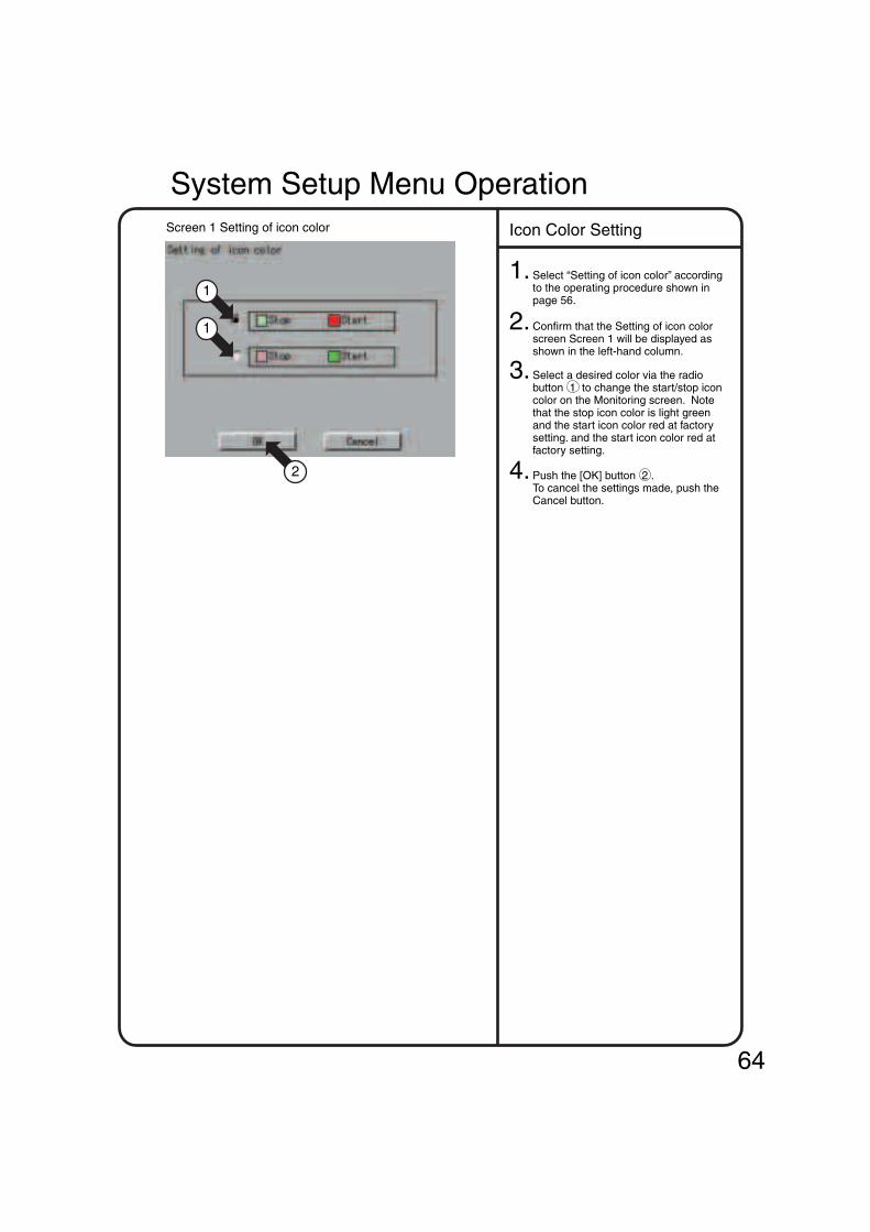
1.Select “Setting of icon color” according to the operating procedure shown in page 56.
2. Confirm that the Setting of icon color screen Screen 1 will be displayed as shown in the left-hand column.
3. Select a desired color via the radio button 1 to change the start/stop icon color on the Monitoring screen. Note that the stop icon color is light green and the start icon color red at factory setting. and the start icon color red at factory setting.
4. Push the [OK] button 2 .To cancel the settings made, push the Cancel button.
Icon Color SettingScreen 1 Setting of icon color
2
1
1
System Setup Menu Operation
64

1.Select “License key input” according to the operating procedure shown in page 56.
2. Confirm that the License key input screen Screen 1 will be displayed as shown in the left-hand column.
3. Push the [Add] button 1 and input an option software license key on the resulting keyboard dialog. In this case, care should be taken for key input because the license key cannot be registered so long as it contains incorrect uppercase or lowercase letters.
4.
3 : Button for switch uppercase to lowercase and vice versa
4 : Button for deleting a character input by pressing the incorrect character key You can delete any number of characters from the cursor position to the left by pushing this button as many times as necessary.
5 : Button for moving the cursorAfter making the necessary settings, push the [OK] button 6 .To cancel the settings made, push the [Cancel] button and return to the License key input screen Screen 1.
After adding the option, push the [OK] button 2 to determine the input license key. Then, push the [OK] button on the restart confirmation screen to restart the Intelligent Touch Controller.
License Key InputScreen 1 License key input
Screen 2 Input Screen
2
1
4
5
6
3
[How to use the keyboard]
System Setup Menu Operation
65

1.Select “Schedule setting” according to the operating procedure shown in page 56.
Before setting a calendar, refer to page 35 to consider what kind of schedule is to be set and perform the following operations.The following shows an example of setting made referring to zone 2 in page35.
This example shows the setting that determines which days in the year schedule to use for special days (such as the summer holidays) requiring air-conditioner control different from that in the regular weekly schedule.
2. Confirm that the Schedule setting screen Screen 1 will be displayed as shown in the left-hand column.
3. Select a schedule from 1 to set or change the calendar.
4. Push the [Calendar Setup] button 2 to display the calendar setup screen Screen 2. Initially, the weekly settings are made. Select a month for change at 3 and a day for change at 4 . Then, select a pattern for the selected day from 5 .
∗ Check a Set checkbox to display a radio button for each pattern.This setting can be made for the coming 13 months.
5. After making the necessary settings, push the [OK] button 6 and return to the Schedule setup screen Screen 1.
Set Schedule and CalendarScreen 1 Schedule Setup
Screen 2 Calendar Setup
1
3 3
2
6
4
5
System Setup Menu Operation
66

1.Select “Schedule Setup” according to the operating procedure shown in page 56.
Before setting an event, refer to page 36 to determine what kind of event is to be set and perform the following operations. The following shows an example of setting made referring to page 36.
2. Confirm that the Schedule setup screen Screen 1 will be displayed as shown in the left-hand column.
3. Select a schedule from 1 to set or change the event(s).
4. Push the [Event setting] button 2 to display an event list (Screen 2).Here, actual schedule operations are set for each of 17 kinds of days (Sunday to Saturday, Ex1 to Ex10). First, use the pull-down menu 3 to determine a day of the 17 kinds of days for which events are to be set. Screen 2 indicates that Mon has been selected.
5. The following describes in order the functions of buttons 4 to 8 . 4 Add :
Use this button to add the new event. Pushing this button causes the Event setup screen Screen 3 on the next page to be displayed. For details on event setup operation, refer to the descriptions given on the next page.
5 Copy : Use this button to make the same setting as for the previously set event. Select the previously set event from 9 . Push the copy button 5 to copy the event.Push the [Modify] button 6 (described below) to modify the copy event.
6 Modify : Use this button to change the previously registered event. Select the event to be changed from 9 and push the [Modify] button 6 .
7 Delete : Use this button to delete the previously registered event. Select the event to be deleted from 9 and push the [Delete] button 6 .
8 Edit Schedules : This button provides the functions similar to those of the above copy button. This button can be used to copy the events set for a set of days (Sunday to Saturday and Ex1 to Ex10) to another set of days (Sunday to Saturday and Ex1 to Ex10). (For details on Edit Schedules, refer to page 71 “Convenient Functions.”)
Set Schedule and EventScreen 1 Schedule Setup
Screen 2 Event List
1
3
10 11
2
4
9
5 6 7
8
System Setup Menu Operation
67

6.Push the Add button or Modify button on the previous page, and the Event setup screenScreen 3 will be displayed. The current settings of events are shown at the left side of the buttons 12 to 17 .The following describes in order the settings of events that can be made. • Event time :
Refers to the event setting time. Display a keyboard for registering the time by pushing the [Modify] button 12 and enter the time.
• Target : Refers to the zone or group of the air-conditioner to be controlled. Push the [Modify] button 13 to select a zone or group for which schedule operations should be performed.
• On / Off : Sets Start, Stop or No change. Use the pull-down menu 14 for this selection.
• Advanced setting : Push the button 18 to display an advanced setting screen Screen 4. The descriptions of the advanced setting are shown on the next page.
After setting the operation and making the advanced setting on the next page, push the [OK] button 19 . To cancel the settings made, push the [Cancel] button 20 to return to Screen 2 on the previous page. When making additional settings, repeat the operations shown in steps 5 and 6. After making the necessary settings, push the [OK] button on Screen 2 of the previous page.
Start / Stop : Select Permitted, Stop Only, Prohibited or No change from the pull-down menu 15
Operation Mode : Select Permitted, Prohibited or No change from the pull-down menu 16 .
Set Temperature : Select Permitted, Prohibited or No change from the pull-down menu 17 .
A full description of each button has been given above.The following discusses how to make the actual settings.To define the new operation, push the [Add] button 4 . To change the previously set operation, push the [Modify] button 6 .
Screen 3 Event Setup
18 19 20
12
13
14
15
16
17
How to make the setting for the remotecontrol at hand[ ]
System Setup Menu Operation
68

7.Push the [Advanced setting] button 18 on the Event setup screen Screen 3 to display an advanced setup screen Screen 4. The current settings of events are shown at the left side of the buttons 21 to 24 . • Operation Mode :
Refers to the operation mode for a zone or group. Select Cool, Heat, Auto, Fan, Set Point or No change. Note that only three modes (Set Point, Fan and No change) are available when a target zone or group (being subject to mode selection) does not provide you with an option for selecting “heating” or “cooling.” In this case, you may select one of the modes from the pull-down menu 21 .Temperature adjustment : Refers to cooling or heating. When “cooling” or “heating” has been set in an air-conditioner (providing you with an option for selecting “heating” or “cooling”), the air-conditioner works according the selected cooling or heating operation mode.
• Set Temperature :Set thetemperature of a zone or group. Push the [Modify] or [Disabled] button 22 according to purpose. When displaying a keyboard to register a temperature and entering a desired temperature on that keyboard, push the [Modify] button. The Disabled button is displayed only when the [Modify] button is pushed once and the desired temperature is set. Push the [Disabled] button to cancel the temperature set through the [Modify] button.
When ventilation is to be scheduled, thefollowing settings can be made.Though this setting menu is displayed regardless of ventilation, no ventilation control takes place even if the setting is made. • Ventilation mode :
Set the ventilation mode.You can select Auto, Normal, All heat exchange or No change from the pull-down menu 23 .
• Ventilation amount :Set the volume of ventilation.You can select Auto (Normal), Weak (Normal), Strong (Normal), Auto (Freshen up), Weak (Freshen up), Strong (Freshen up) or No change from the pull-down menu 24 .
After making the advanced settings, push the [OK] button 25 to return to Screen 3 on the previous page.
Screen 4 Advanced Setup
25
21
22
23
24
System Setup Menu Operation
69

70
1.Select “Schedule Setup” according to the operating procedure shown in page 56.
2. Confirm that the Schedule setup screen Screen 1 will be displayed as shown in the left-hand column.
3. Select a schedule from the list 1 to change the name.
4. Display a keyboard screen by pushing the [Modify Name] button 2 and enter a desired schedule name on that keyboard.A schedule name can be entered in up to 16 characters.
1. Select a specify day from the pull-down menu 1 on the event list screen to change the name.
2. Confirm that the [Modify Name] button 2 will be displayed for the selected special day.
3. Display a keyboard screen by pushing the [Modify Name] button 2 and enter a desired special day name. A special day name can be entered in up to 8 characters.
1. Last, enable or disable a schedule. Perform the following operations on the schedule setup screen Screen 3. Select a schedule from the list 1 and enable or disable the schedule at 2 . On the confirmation screen, push the [Yes] button to enable the schedule and the [No] button to disable it. Then, check to see the display “Enabled” or “Disabled” in right side of 1 to confirm that the schedule has been enabled or disabled successfully.
Even if the calendar or event is set, no schedule function works unless the schedule is enabled.
Screen 1 Schedule Setup
Screen 2 Event List
Screen 3 Schedule Setup
2
1
1
1
2
2
Change Schedule Name
Change Special Day Name
Enable or Disable Schedule
System Setup Menu Operation

71
1.Select “Schedule Setup” according to the operating procedure shown in page 56.
∗ When it is necessary to reuse an event set for a day of the week, this function greatly helps you copy the event to the other day of the week.
Example: When using the same schedule for Monday to Friday, set an event for Monday, then copy it for Tuesday to Friday to eliminate the efforts required for making the setting for each day of the week.
2. Confirm that the schedule setup screen Screen 1 will be displayed as shown in the left-hand column.
3. Select a schedule from 1 to copy the event.
4. Push the [Event setting] button 2 to display the event setup screen Screen 2.
5. Push the [Event Schedules] button 3 to display the event manipulation screen Screen 3.
The following describes in order the functions of buttons 4 to 10 .Select a day of the week for a copy source at 4 and that for a copy destination at 5 . In an example of the left-hand column, “Mon” is selected as a day of the week for the copy source and “Tues” as that for the day of the copy destination.Then, select the event to be copied at 6 and push the [>] button 8 to copy the event No. 01 from Monday to Thursday.Push the [>>] button 9 to copy all the events from Monday to Thursday,Push the [<] button 10 once to delete the event copied incorrectly from 7 . You must push the [<] button 10 as many times as necessary to delete multiple incorrect events. After making the necessary settings, push the [OK] button 11 to return to the event list screen Screen 2.
Screen 1 Schedule Setup
Screen 2 Event List
Screen 3 Event Manipulation
2
1
6 7
9 8 10 11
3
4 5
Convenient Function 1Copy in Units of Events
System Setup Menu Operation

1.Select “Schedule Setup” according to the operating procedure shown in page 56.
∗ When it is necessary to resume a calendar setting made for schedule 1, this function greatly helps you copy the calendar setting to the other schedule(s).
Example : When reusing the same calendar setting (such as the summer holiday) for the other schedule, make the calendar setting for schedule 1, then copy it for the other schedule to eliminate the efforts required for making the same setting for each of the other schedules.
2. Confirm that the schedule setup screen Screen 1 will be displayed as shown in the left-hand column.
3. Push the [Edit Schedules] button 2 to display the data manipulation screen Screen 2.
(For setup item copy)Select a schedule for a copy source at 3 and that for a copy destination at 4 . In an example of the left-hand column, the schedule of the copy source is schedule 1 and that of the copy destination schedule 2. Next, select the setup item (to be copied) of schedule 1 from the pull-down menu 5 . The following setup items can be selected. • Overwriting all setup items • Overwriting only the calendar setup itemAfter selecting either of the above items, push the [Apply] button 6 . Last, push the [OK] button 7 to terminate the copy procedure. To cancel the settings made, push the [Cancel] button 8 and return to the schedule setup screen Screen 1.
(For setup item deletion)Select the schedule to be deleted at 4 . Next, select the setup item to be deleted from the pull-down menu 5 . The following setup items can be selected. • Delete all the setup items • Delete only the calendar setup item
After selecting either of the above setup items, push the [Apply] button 6 . Last, push the [OK] button 7 . To cancel the settings made, push the [Cancel] button 8 and return to the schedule setup screen Screen 1.
Screen 1 Schedule Setup
Screen 2 Data Manipulation
2
1
34
7 8
5 6
Convenient Function 2Copy or Delete in Units of Schedules
System Setup Menu Operation
72

1. See page 56 and select Change Over Settings.
2. Screen 1 Change Over Settings, which is shown on the left, appears.
This screen shows current status (enabled / disabled) of each cooling / heating automatic change over group, control method, set value of temperature difference, and the number of the registered indoor unit groups.
3. Touch a cooling / heating automatic change over group to be set or changed as shown by 1 , and press the [Modify] button 2 .
4. Screen 2 Cooling / Heating Automatic Change Over Group Settings, which is shown on the left, appears. First, select a control method at 3 . The following three control methods are available.
5. Set a temperature difference value for cooling / heating automatic change over with the [modify] button 4 .(Setting range: 1°C - 7°C)
6. At 5 , select an indoor unit to be added to the cooling / heating automatic change over group which is currently selected, and press the button 6 to add.To delete an indoor unit from the cooling / heating automatic change over group, select it at 7 , and press the button 8 .7. To change the order of the registered indoor group 9 , select an indoor unit to be changed at 7 , and move it with the Up button or the Down button 10 .Memo: When the control method “Fixed” is selected, the indoor unit displayed on the top in the box 9 becomes the representative one.When the operation method “Operating” is selected, a search for representative unit is performed starting from the top.
9. On the screen 1, select the cooling / heating automatic change over group to be enabled at 1 , and press the button 15 to enable. (Confirm the group status (enabled / disabled) displayed on 16 .)Only the cooling / heating automatic change over group set to enabled is controlled automatically.
10. Lastly, when all the setting changes are correct, press the [OK] button 17 . (To cancel, press the Cancel button 18 .) When the [OK] button 17 is pressed, the screen 3 Confirmation Display appears.When there is no problem in setting change, press the [Yes] button 13 . This menu is ended, and System Setup Menu appears.(When the [No] button 14 is pressed, the screen 1 appears.)
8. When all settings for this cooling / heating automatic change over group (control method, temperature difference, indoor unit registration) are completed, press the [OK] button 11 (To cancel, press the [Cancel] button 12 .)Screen 3 Confirmation Display appears.When there is no problem in setting change, press the [Yes] button 13 .Screen 1, which is shown on the top on this page, appears.(To add or change the settings in the cooling / heating automatic change over group mentioned above, press the [No] button 14 . Screen 2 appears.)
For details of each control method, see page 37.
Before performing Change Over Settings, read thoroughly the section Change Over Settings on page 37, and perform the following procedure.
Operation of Change Over SettingsScreen 1 Change Over Settings
Screen 2 Cooling/Heating Automatic Change Over Group Settings
Screen 3 Confirmation
System Setup Menu Operation
• Fixed • Operating • Average
16
164
163
1717 1818
1710
177
1710 1711 1712
175
31
3936
38
315 32
1613 1614
73

1. See page 56 and select Temperature Limit Settings
2. Screen 1 Temperature Limit Settings, which is shown on the left, appears.
This screen shows current status (enabled / disabled) of room temperature upper / lower limit control group, and setting status of lower temperature limit, upper temperature limit, and the number of registered indoor unit groups.
3. Touch a room temperature upper / lower limit control group to be set or changed as shown by 1 , and press the [Modify] button 2 .
4. Screen 2 Room Temperature Upper / Lower Limit Control Group Settings, which is shown on the left, appears. First, at 3 , select the indoor unit to be added to the room temperature upper / lower limit control group which is currently selected, and press the button 4 to add. To delete an indoor unit from the group, select it at 5 , and press the button 6 .
5. Set a lower limit of room temperature with the [Modify] button 7 , and an upper limit of room temperature with the [Modify] button 8 .
Setting range : 2°C - 14°C for lower limit, 34°C - 50°C for upper limit
6. When all settings for this room temperature upper / lower limit control group (indoor unit registration, settings of upper limit and lower limit) are completed, press the [OK] button 9 .(To cancel, press the [Cancel] button 10 .)Screen 3 Confirmation Display appears. When there is no problem in setting change, press the [Yes] button 11 .Screen 1, which is shown on the top on this page, appears.
To add or change the settings in the room temperature upper / lower limit control group mentioned above, press the [No] button 12 . Screen 2 appears.
7. On the screen 1, select a room temperature upper / lower limit control group to be enabled at 1 , and press the button 13 to enable.
Confirm the group status (enabled / disabled) displayed on 14 .
Only the room temperature upper / lower limit control group set to enabled is controlled automatically.
8. Lastly, when all the setting changes are correct, press the [OK] button 15 . (To cancel, press the [Cancel] button 16 .)When the [OK] button 16 is pressed, the screen 3 Confirmation Display appears.When there is no problem in setting change, press the [Yes] button 11 . This menu is ended, and System Setup Menu appears. (When the [No] button 12 is pressed, the screen 1 appears.)
Before performing Temperature Limit Settings, read thoroughly the section Temperature Limit Settings on page 42, and perform the following procedure.
Operation of Temperature Limit SettingsScreen 1 Temperature Limit Settings
Screen 2 Room Temperature Upper/Lower Limit Control Group Settings
Screen 3 Confirmation
11
113 12
1414
7 8
11 12
15 16
33
6
4
55
99 1010
System Setup Menu Operation
74

System Setup Menu Operation
1. See page 56 and select Heating Optimization Settings.
2. Screen 1 Heating Optimization Settings, which is shown on the left, appears.
This screen shows current registration status of Heating Optimization Settings.
3. Touch an indoor unit to be added as shown by 1 , and press the button 2 to add.To deactivate this control, select an indoor unit at 3 , and press the button 4 .
4. Lastly, when all indoor units are registered, press the [OK] button 5 .(To cancel, press the [Cancel] button 6 .)Screen 2 Confirmation Display appears. When there is no problem in setting change, press the [Yes] button 7 . This menu is ended, and System Setup Menu appears.
To continue the change, press the [No] button 8 . The screen 1 appears.
Before performing Heating Optimization Settings, read thoroughly the section Heating Optimization Settings on page 45, and perform the following procedure.
Operation of Heating Optimization SettingsScreen 1 Heating Optimization Settings
Screen 2 Confirmation
31
42
43
44
55 66
7 8
75
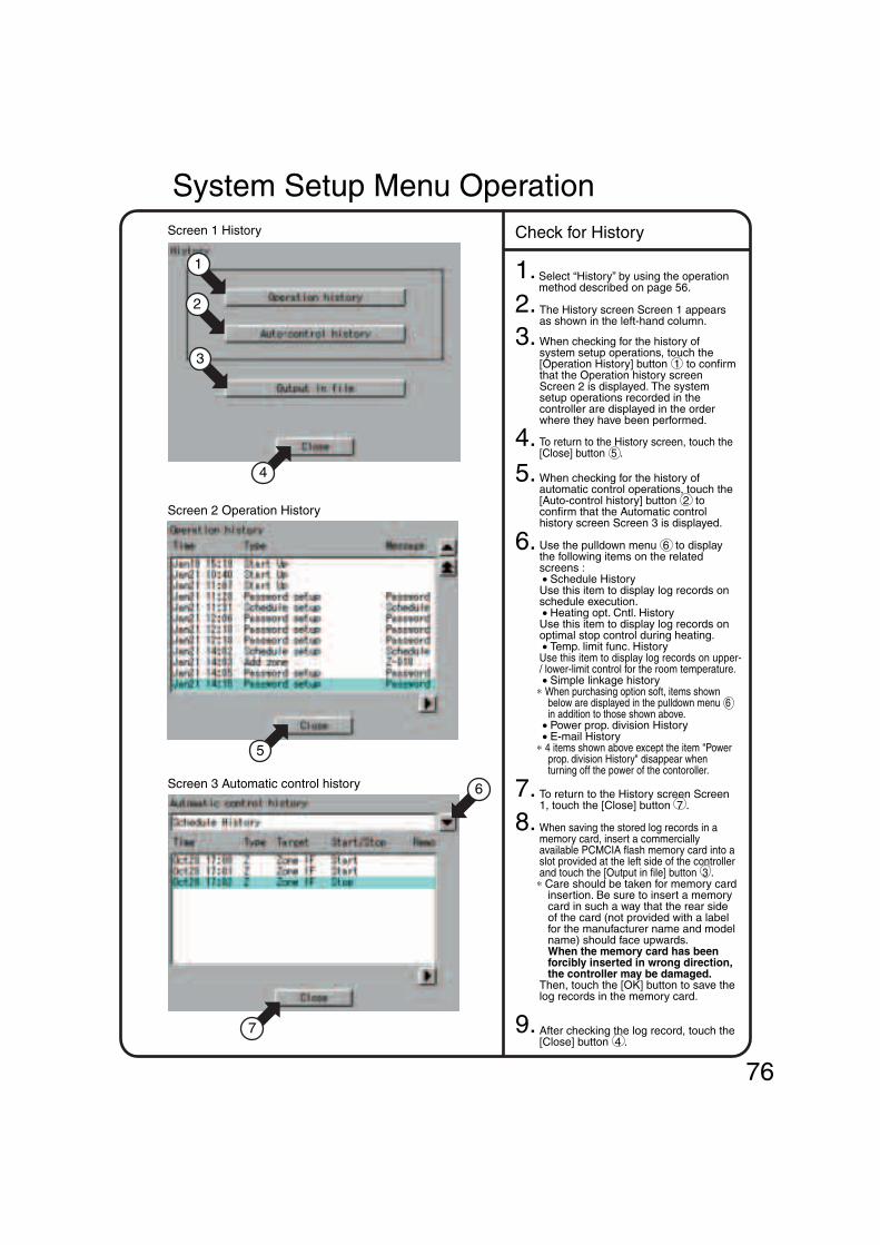
Screen 1 History
Screen 2 Operation History
Screen 3 Automatic control history
1. Select “History” by using the operation method described on page 56.
2. The History screen Screen 1 appears as shown in the left-hand column.
3.
4. To return to the History screen, touch the [Close] button 5 .
5. When checking for the history of automatic control operations, touch the [Auto-control history] button 2 to confirm that the Automatic control history screen Screen 3 is displayed.
6. Use the pulldown menu 6 to display the following items on the related screens : • Schedule HistoryUse this item to display log records on schedule execution. • Heating opt. Cntl. HistoryUse this item to display log records on optimal stop control during heating. • Temp. limit func. HistoryUse this item to display log records on upper- / lower-limit control for the room temperature. • Simple linkage history
∗ When purchasing option soft, items shown below are displayed in the pulldown menu 6 in addition to those shown above.
• Power prop. division History • E-mail History
∗ 4 items shown above except the item "Power prop. division History" disappear when turning off the power of the contoroller.
7. To return to the History screen Screen 1, touch the [Close] button 7 .
9. After checking the log record, touch the [Close] button 4 .
8. When saving the stored log records in a memory card, insert a commercially available PCMCIA flash memory card into a slot provided at the left side of the controller and touch the [Output in file] button 3 .
∗ Care should be taken for memory card insertion. Be sure to insert a memory card in such a way that the rear side of the card (not provided with a label for the manufacturer name and model name) should face upwards.When the memory card has been forcibly inserted in wrong direction, the controller may be damaged.
Then, touch the [OK] button to save the log records in the memory card.
Check for History
1
6
2
3
5
4
7
When checking for the history of system setup operations, touch the [Operation History] button 1 to confirm that the Operation history screen Screen 2 is displayed. The system setup operations recorded in the controller are displayed in the order where they have been performed.
System Setup Menu Operation
76

System Setup Menu Operation
1. Select “Setting of E-mail” according to the operating procedure shown in page 56.
∗ The e-mail function (option) comes standard with the Web function.
2. Confirm that the Setting of Email screen Screen 1 will be displayed as shown in the left-hand column.
3. Select “Enable” or “Disabled” for the e-mail function 1 . When “Disabled” has been selected, there is no additional setup operation for the e-mail function. To continue the setup operation, be sure to select the [OK] button 27 .
4. You can monitor the current setting in the display area 2 .
5. Push the [Server Setting] button 3 to display the Setting of E-mail server screen Screen 2 will be displayed as shown in the left-hand column.
6. Push the [Modify] button 4 and enter an SMTP server address on the input screen.
7. Push the [Modify] button 5 and enter an SMTP server port number on the input screen.
8. Select “Enabled” or “Disabled” for the POP server 6 .
9. Push the [Modify] button 7 and enter a POP server address on the input screen.
10. Push the [Modify] button 8 and enter a POP server port number on the input screen.
11. Push the [Modify] button 9 and enter a POP server user ID on the input screen.
12. Push the [Modify Password] button 10 and enter a POP server password on the input screen.
13. Last, push the [OK] button 11 to return to the Setting of E-mail screen Screen 1.(To cancel the settings made, push the [Cancel] button.)
Setting of E-mailScreen 1 Setting of E-mail
Screen 2 Setting of E-mail server
527
511
1
2
4
5
7
8
10
6
9
14.Push the [Transmn Set] button 12 to display the Setting of E-mail transmission screen on the next page Screen 3.
3 12 20
1. See page 56 and select Touch Panel Calibration.
2. Screen 1 Touch Panel Calibration, which is shown on the left, appears.
3. Follow the instruction shown on the screen and press the intersection of the crosshairs 1 and keep it pressed for about 1 second.
4. The crosshairs are moved. Repeat the operation described in step 3 on a total of five points.When calibration is finished, the System Setup automatically appears within 30 seconds.
Screen 1 Touch Panel Calibration Touch Panel Calibration
1
77

15.
16.
17.
Push the [Modify] button 13 and enter a retransmission interval on the input screen.
The retransmission interval is an e-mail retransmission interval when faults occur consecutively with the equipment. This interval time (hour) must be a value from 1 to 72. Initially, it is set to 2 hours.
Push the [Modify] button 14 and enter an ITC identifier on the input screen. The name specified here is displayed in the Subject field during e-mail transmission.
When adding an air-conditioner for fault confirmation by e-mail, select the air-conditioner at 15 and push the [<<] button 16 .
When deleting an air-conditioner for fault confirmation by e-mail, select the air-conditioner at 17 and push the [>>] button 18 .
After finishing the necessary edit operations, push the [OK] button 19 to return to the Setting of E-mail screen on the previous page Screen 1.
To cancel the settings made, push the [Cancel] button.
18.Push the [Mail add. Set] button 20 on the previous page to display the Setting of E-mail address screen Screen 4.
20.When sending test e-mail, select a destination e-mail address at 22 and push the [Trial mail] button 25 .
21.After making the necessary settings, push the [OK] button 26 to return to the Setting of E-mail screen on the previous page Screen 1.
To cancel the settings made, push the [Cancel] button.
19.When adding an e-mail address for fault notification by e-mail, push the [Add] button 21 and enter the e-mail address on the input screen.
Note that a maximum of 3 e-mail addresses can be registered.
When deleting an e-mail address, select the address at 22 and push the [Delete] button 23 .In addition, when changing the registered e-mail address, select the address at 22 and push the [Modify] button 24 .
Screen 3 Setting of E-mail transmission
Screen 4 Setting of E-mail address
313 314
17
16
18
15
22
25
19
26
22.After finishing the necessary setting for e-mail, push the [OK] button 27 .
To cancel the settings made, push the [Cancel] button.
21 323 24
System Setup Menu Operation
78
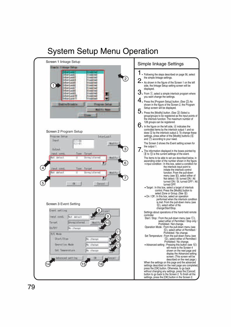
System Setup Menu Operation
Screen 2 Program Setup
Screen 3 Event Setting
1. Following the steps described on page 56, select the simple linkage settings.
2. As shown in the figure of the Screen 1 on the left side, the linkage Setup setting screen will be displayed.
3. From 1 , select a simple interlock program where you want change the settings.
4. Press the [Program Setup] button. (See 2 ) As shown in the figure of the Screen 2, the Program Setup screen will be displayed.
5. Press the [Modify] button. (See 3 ) Select a group/groups to be registered as the input points of the interlock function. The maximum number of 128 groups can be registered.
6. In the figure on the left side, 4 indicates the controlled items by the interlock output 1 and so does 5 by the interlock output 2. To change these settings, press either of the [Modify] buttons ( 6 and 7 ) according to your need. The Screen 3 shows the Event setting screen for the output 1.
7. The information displayed in the boxes pointed by 8 to 13 is the current settings of the event. The items to be able to set are described below, in ascending order of the number shown in the figure. • input condition : In this box, select a condition for
the interlock input point to initiate the interlock control function. From the pull-down menu (see 8 ), select either of Not detect / St. turned ON / All. turned ON / St. turned OFF / All. turned OFF.
• Target : In this box, select a target of interlock control. Press the [Modify] button to select Zone or Group. (See 9 )
• On / Off : In this box, select an operation performed when the interlock condition is met. From the pull-down menu (see 10 ), select either of No change/Start/Stop.
Settings about operations of the hand-held remote controller Start / Stop : From the pull-down menu (see 11 ),
select either of Permitted / Stop only / Prohibited / Not change.
Operation Mode : From the pull-down menu (see 12 ), select either of Permitted / Prohibited / No change.
Set Temperature : From the pull-down menu (see 13 ), select either of Permitted / Prohibited / No change.
• Advanced setting : Pressing this button (see 14 ) will move to the Screen 4 shown on the next page and display the Advanced setting screen. (This screen will be described on the next page.)
When the settings on this page and the advanced settings described on the next page are completed, press the [OK] button. Otherwise, to go back without changing any settings, press the [Cancel] button to go back to the Screen 2. To finish all the settings, press the [OK] button in the Screen 2.
Screen 1 linkage Setup Simple linkage Settings
79
1
2
3
6
7
4
5
8
9
10
11
12
13
14 15 16

System Setup Menu Operation
8. In the Screen 3 Event setting on the previous page, pressing the [Advanced setting] (See 14 ) will display the Advanced setting screen shown in the Screen 4 on the left side.?The information displayed in the boxes pointed by 17 to 20 is the current settings of the event. • Operation Mode : In this box, select an operation
mode specified to Zone or Group. From the pull-down menu (see 17 ), select either of Cool, Heat, Auto, Fan, Set Point*, and No change.
* Set Point can be used to order the indoor unit, which has no right to select either cooling or heating operation in the VRV, to perform the temperature control operation other than the fan operation. When the interlock condition is met, this indoor unit will operate in the same operation mode as that of another indoor unit which has the right to select either cooling or heating mode. For the same reason, even if the cooling / heating mode is set to an indoor unit which has no right to select such modes, this unit operates in the same operation mode as that of another indoor unit which has the right to select either cooling or heating mode. For detailed information about the right to select the cooling / heating mode, please refer to the operation manual of the air-conditioning unit.
• Set Temperature : In this box, set a temperature of Zone or Group. Pressing the [Modify] button (see 18 ) will display the keyboard for registering a temperature, where you can input the desired temperature. The [Disable] button will be shown after pressing the [Modify] button once to set a temperature. Pressing the [Disable] button will cancel the temperature specified by the Modify operation described above.
To the HRVs included in the interlock operation targets, the settings described below can be made. However, this setting menu will be displayed even when the HRVs are not included in the targets, but any settings made in this menu will do nothing. • Ventilation mode : In this box, set the ventilation
mode. From the pull-down menu (see 19 ), select either of Auto / Normal / All heat exchange / No change.
• Ventilation amount : In this box, set the ventilation amount. From the pull-down menu (see 20 ), select either of Auto (Normal)/Weak (Normal) / Strong (Normal) / Auto (Freshen up) / Weak (Freshen up) / Strong (Freshen up) / No change.
When the advanced settings are completed, press the [OK] button to go back to the Screen 3 shown on the previous page. Pressing the [OK] buttons in the Screen 3 and the Screen 2 continuously to go back to the Screen 1 shown on the previous page. The next step is to specify a name of the simple interlock, followed by the validity / invalidity setting. (Details of these settings will be described in the next page.)
Screen 4 Advanced setting
80
17
18
19
20

System Setup Menu Operation
Screen 6 Simple Interlock Setting
1. Following the steps described on page 56, select the simple interlock settings.
2. As shown in the figure of the Screen 5 on the left side, the simple linkage setup screen will be displayed.
3. From 1 , select a simple interlock program of which you want change the name.
4. Pressing the [Modify Name] button (see 2 ) will display the keyboard, where you can input the desired name of the interlock function. (The name of the simple interlock function can contain 16 characters maximum.)
The last thing to do is to switch between the validity / invalidity settings of the simple interlock function. In the simple interlock setting screen shown in the figure of the Screen 6, follow the steps described below :From 1 , select a simple interlock program for which you want switch between the Enable / Disable settings.
Then pressing the button 2 will switch between the Enable / Disable settings.
In the confirmation screen displayed, press [Yes] to make the change effective or [No] to cancel the change. See the indication of Enable / Disable on the right side of 1 to check whether the setting you made is correctly reflected.
[Note] Even if you have made the simple interlock settings, failing to Enable the simple interlock function in this menu will not activate the function.
Screen 5 Simple linkage Setup Simple Interlock Change Name
81
Simple InterlockValidity/Invalidity Setting
1
1
2
2
1.

82
1.See page 56 and select Version Information.
2. Screen 1 Version Information, which is shown on the left, appears.The figure on the left shows an example. It may be different from the actual version.
3.When the version number has been checked, press the [Close] button 1 .
This is a menu for checking the version number of the software for the intelligent Touch Controller currently used. Generally it is not necessary to check.
Version InformationScreen 1 Version Information
1
System Setup Menu Operation
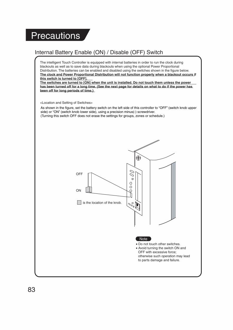
83
Precautions
Internal Battery Enable (ON) / Disable (OFF) Switch
The intelligent Touch Controller is equipped with internal batteries in order to run the clock during blackouts as well as to save data during blackouts when using the optional Power Proportional Distribution. The batteries can be enabled and disabled using the switches shown in the figure below.The clock and Power Proportional Distribution will not function properly when a blackout occurs if this switch is turned to [OFF].The switches are turned to [ON] when the unit is installed. Do not touch them unless the power has been turned off for a long time. (See the next page for details on what to do if the power has been off for long periods of time.)
<Location and Setting of Switches>
Note
OFF
ON
is the location of the knob. RESET
As shown in the figure, set the battery switch on the left side of this controller to “OFF” (switch knob upper side) or “ON” (switch knob lower side), using a precision minus(-) screwdriver.(Turning this switch OFF does not erase the settings for groups, zones or schedule.)
• Do not touch other switches. • Avoid turning the switch ON and
OFF with excessive force; otherwise such operation may lead to parts damage and failure.

Maintenance
• When the surface of the LCD or the main unit of the intelligent Touch Controller is soiled, wipe the soil off with a piece of cloth soaked in a diluted neutral detergent and wrung sufficiently.
Note
LCD Maintenance
When Leaving the Product Turned OFF for a Long Time
When you leave the intelligent Touch Controller turned OFF for a long time (6 months or longer), turn the switch OFF to maintain the battery.
• The intelligent Touch Controller has a built-in battery for operating the clock in power failure.The battery mentioned above is for power failure only and it may be completely discharged if no power is provided for a long time.(The capacity is worth about 2 years of in total if no power is supplied.)
• To use the intelligent Touch Controller again, turn the switch ON.
As shown in the figure, set the battery switch on the left side of this controller to “OFF” (switch knob upper side) or “ON” (switch knob lower side), using a precision minus(-) screwdriver.(Turning this switch OFF does not erase the settings for groups, zones or schedule.)
[Setting the switch]
Note
If electric components in the intelligent Touch Controller are charged with static electricity, it may cause failure.Be sure to discharge the static electricity accumulated in your body before attempting any operation.To discharge yourself, touch a grounded metal object (control panel, etc.).
RESET
is the location of the knob.
OFF
ON
Caution
84
Do not use thinner, organic solvent, strongly acid solution, etc.The print may fade or wear out and discolor.Forced rubbing with hard cloth may cause damage to the liquid crystal display unit.Remove stains, always using a soft waste cloth.If the unit is stored with water droplets and stains sticking to the liquid crystal display unit, a blot may be made and the coating may come off.
• Do not touch other switches. • Avoid turning the switch ON and
OFF with excessive force; otherwise such operation may lead to parts damage and failure.

85
Troubleshooting
Before Having the Product Serviced
Item Description and Corrective Action
When Backlight Auto OFF is set for Backlight Setup of the intelligent Touch Controller, the light goes out if the screen is left untouched for a certain time.Touch the screen with the pen provided. The display comes back on.
The display of the intelligent Touch Controller has gone out.
Backlight Auto OFF is a function to automatically turn the backlight OFF if it is left untouched for a certain time.If the display is Set / Prop, System Setup, etc., the light does not go out automatically.
The backlight does not go out when Backlight auto OFF is set.
The intelligent Touch Controller cannot be operated or monitoring is not available.
Press and hold down the reset button on the left screen of the intelligent Touch controller for 5 seconds.Pressing this switch initialize the intelligent Touch Controller.Pressing this switch does not erase the settings for groups, zones or schedule.
intelligent Touch Controller
Note
If electric components in the intelligent Touch Controller are charged with static electricity, it may cause failure.Be sure to discharge the static electricity accumulated in your body before attempting any operation.To discharge yourself, touch a grounded metal object (control panel, etc.).
RESET
RESET
Caution
Press the RESET button stamped as “RESET” thereunder with something like a thin shaft.
• Do not touch other switches.
• Avoid turning the switch ON and OFF with excessive force; otherwise such operation may lead to parts damage and failure.

86
The intelligent Touch Controller is designed in such a way that the buzzer sounds when any part of the screen is pressed. It is normal.
Item Description and Corrective Action
On the Monitoring screen, buzzer sounds when an area not allocated for a button for operation is pressed.
While the Monitoring screen is shown, the screen is updated every 3 seconds to show the latest status of air conditioners. The screen may look flickering when the update is made. It is normal.
The screen flickers at a regular interval.
Updating of the display may take some time depending on the communication status with the air conditioners connected. Update is completed in a few seconds.
Touching the screen of the intelligent Touch Controller does not change the display soon.
There may be found some dots that are never illuminated or always illuminated on a certain part of the LCD of the intelligent Touch Controller. It is normal.The LCD may inherently generate unevenness due to change of temperature, which is normal.
LCD
On the Zone Monitoring screen, the filter or element sign shown is not turned out unless the filter or element signs for all of the air conditioners in the zone are reset.Check for any air conditioner showing cleaning sign apart from the air conditioners cleaned in the zone.
On the Zone Monitoring screen of the intelligent Touch Controller, a filter or element sign was shown for a certain zone.Cleaning the filter or element of air conditioners and resetting the cleaning sigh with a remote control does not turn out the filter or element sign.
The positions of buttons on the touch panel may be shifted over time. See page 76 and perform touch panel calibration.
Pressing an operation button on the screen of the intelligent Touch Controller sounds the buzzer but operation is not accepted.
When adding an air conditioner to be connected to the intelligent Touch Controller, trial running of the intelligent Touch Controller, as well as of the air conditioner, is required.
When trial running of the intelligent Touch Controller has not been performed, contact our representative.
An air conditioner to be connected to the intelligent Touch Controller has been added but the added air conditioner cannot be monitored on the Monitoring screen of the intelligent Touch Controller.
When iPU, BAC net Gateway is connected, Permitted / Inhibited setting of the remote control cannot be made with the intelligent Touch Controller. When double intelligent Touch Controller control is performed, one of the two intelligent Touch Controllers cannot make Permitted / Inhibited setting.
The intelligent Touch Controller does not allow setting of Permitted / Inhibited of the remote control.
Before Having the Product Serviced

87
Is the indication System Ctal Mng on the Monitoring screen, as shown below?
This indication is shown in the following cases.
When iPU, BAC net Gateway is connected to the intelligent Touch Controller, the low order control inhibit setting is available for iPU, BAC net Gateway.The lower order control inhibit is a setting that inhibits operation of air conditioners from the intelligent Touch Controller central management controller and ON / OFF controller and enables commands from iPU, BAC net Gateway only. When this setting is made, System Ctal Mng indication is shown on the intelligent Touch Controller.When the setting is released, the System Ctal Mng indication disappears and operation with the intelligent Touch Controller becomes available.
Item Description and Corrective Action
Collective Operation, Start and Stop buttons are not shown on the Monitoring screen of the intelligent Touch Controller and operation of air conditioners is made impossible.
Before Having the Product Serviced
System Ctal Mng indication?

88
The followings are possible causes. Check the followings.1. Is the stop operation performed with the remote control of the
air conditioner?2. When a central unit is connected in addition to this unit, is the
stop operation performed with the central unit?3. Was the power supply for air conditioner interrupted?4. Is the schedule of stopping the air conditioner registered with
the schedule function of the unit?5. Is Heating Optimization function of this unit activated?(The
above function stops the air conditioner during the heating operation to prevent warm air when the thermo-switch is turned off.) (For details, see P45, 46.)
Item Description and Corrective Action
The air conditioner is supposed to operate, but it is stopped.
The followings are possible causes. Check the followings.1. Is the start operation performed with the remote control of the
air conditioner?2. When a central unit is connected in addition to this unit, is the
start operation performed with the central unit?3. Is the schedule of starting the air conditioner registered with the
schedule function of the unit?4. Is Temperature Limit function of this unit activated?(The above
function operates the air conditioner automatically to avoid excessive increase or decrease of room temperature.) (For details, see P42-44.)
The air conditioner is supposed to be stopped, but it is operating.
The followings are possible causes. Check the followings.1. Is the set temperature or the operation mode changed with the
remote control of the air conditioner?2. When a central unit is connected in addition to this unit, is the
set temperature or the operation mode changed with the central unit?
3. Is the schedule of changing the set temperature or the operation mode registered with the schedule function of the unit?
4. Is Change Over function of this unit activated?(The above function changes the operation mode and set temperature of the air conditioner automatically to maintain an optimum room temperature. (For details, see P37-41.)
The set temperature or the operation mode of the air conditioner has been changed.
Before Having the Product Serviced

89
System Compulsory Stop indication?
Is the indication System Compulsory Stop on the Monitoring screen, as shown below?This indication is shown in the following cases.
When compulsory stop command is input to central management devices (central remote controller, ON / OFF controller, etc.) including the intelligent Touch Controller, the indication appears.Inputting compulsory command stops all air conditioners connected to the central management device. While the command is input, neither the central management devices nor remote control can operate air conditioners.When the compulsory stop input command is canceled, the System Compulsory Stop disappears, which allows control with the intelligent Touch Controller.
Item Description and Corrective Action
Collective Operation, Start and Stop buttons are not shown on the Monitoring screen of the intelligent Touch Controller and operation of air conditioners is made impossible.
Before Having the Product Serviced
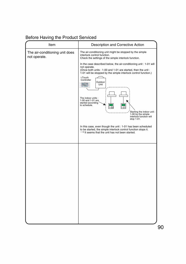
90
1-00 1-01
i-Touch Controller
Outdoor Unit
The indoor units : 1-00 and 1-01 are started according to schedule.
Starting the indoor unit :1-00 by the simple interlock function will stop 1-01.
The air-conditioning unit might be stopped by the simple interlock control function. Check the settings of the simple interlock function.
In the case described below, the air-conditioning unit : 1-01 will not operate. (Once both units : 1-00 and 1-01 are started, then the unit : 1-01 will be stopped by the simple interlock control function.)
Item Description and Corrective Action
The air-conditioning unit does not operate.
Before Having the Product Serviced
In this case, even though the unit : 1-01 has been scheduled to be started, the simple interlock control function stops it. It seems that the unit has not been started.

Emergency Procedure for intelligent Touch Controller Failure
91
As a temporary measure before our service personnel investigates into the problem, turn OFF the power supply breaker of the intelligent Touch Controller. This allows all kinds of operation with the remote control of air conditioners in about 5 minutes.When there is any other central management device, turn the power OFF for all of the devices.
Item Description and Corrective Action
Failure occurs in the intelligent Touch Controller while the remote control is disabled with the intelligent Touch Controller and start / stop setting, etc. of air conditioners cannot be made.

When it is desired to adjust screen brightness, contrast and buzzer sound level
92
The screen brightness, contrast and buzzer sound level are factory adjusted properly before shipment, but in case where the screen is hard to see and the buzzer is hard to hear, for example, according to the actual installation condition and usage, the screen brightness, contrast and buzzer sound level can be adjusted by the following method.
Item Description and Corrective Action
Screen brightness, contrast and buzzer sound adjustment is desired.
Adjust the volume (variable resistor) on the left side of the intelligent Touch controller with a Phillips head screwdriver while checking each level.The buzzer sound, screen brightness and screen contrast volume switches are located in sequence from the top as shown below.
[Adjustment Method]
If electric components in the intelligent Touch Controller are charged with static electricity, it may cause failure.Be sure to discharge the static electricity accumulated in your body before attempting any operation.To discharge yourself, touch a grounded metal object (control panel, etc.).
Note
RESET
loud low
bright dark
pale dark
Caution
Buzzer sound adjusting volume
Liquid crystal backlight brightness adjusting volume
Contrast adjusting volume
• Since each volume is a precision component part, do not turn the volume switch with excessive force.It should be noted that a fault is caused to the switch.
• Do not touch other switches.(The buzzer sound volume and liquid crystal backlight
brightness can be adjusted with the volume switch described above; normally, however, no such adjustment is required.)

Connecting Unification adaptor allows using the contact for normal and abnormal operation signal and collective start/stop with a contact. For details, contact the vendor you purchased the product from.Also, by connecting DIII NET-plus adaptor, it is possible to operate and monitor the indoor units of 64 groups (intelligent Touch Controller plus DIII NET – plus adaptor–128 groups in total) additionally.
Monitoring from PC is possible by WebE-mail functions.(Optional intelligent Touch Controller Web Software is necessary)
CN2 LAN F1,F2
F1,F2
F1,F2
F1,F2 F1,F2 F1,F2
F1,F2 F1,F2
DIII NET-plus adaptor
RS-232C
Up to 64 groups maximum
Up to 64 groups maximum
Up to 16 units maximum
Up to 16 units maximum
Force stop command
Measuring meter (max 3 units)
Measuring meter (max 3 units)
Power supply100 - 240 VAC
50/60 Hz
LN
L,N(L1,L2)
switchFuse(10A)
Grounding work
93
Options
Central monitoring panel(Collective start, stop and error monitoring with contact)
Unification adaptor for computerized control
(Where Power Proportional Distribution Card as option is used)
(The number of connectable indoor units is up to 64 units maximum, where the Power Proportional Distribution Card as option is used.)
(Where Power Proportional Distribution Card as option is used)
(The number of connectable indoor units is up to 64 units maximum, where the Power Proportional Distribution Card as option is used.)
Outdoor unit
Outdoor unit

Specification
Dimensions
Power
Power consumption
Force stop input
Size
Mass
AC100 - 240V 50/60Hz
10 W maximum
230 × 147 × 107 (W × H × D)
1.2kg
Normally-open contact
Contact current approximately 10 mA
The specification and appearance of the product may be modified for improvement without prior notice.
147 90
230 50 57
94
Specification

After-sales Service
95
After-sales Service
• To have the product repaired, prepare the following information
• Repair after the guarantee period for free repairContact the vendor. When the functions can be maintained by repair, the product will be repaired according to the request and the customer will be charged.(Guarantee period ... one year from the date of installation)
• Model
• Date of installation
• Circumstances - as detailed as possible
• Address, name, phone number
• QuestionsFor after-sales service, contact the vendor you purchased the product from or the nearest service station.
• TransferTransfer requires professional technique. Be sure to contact the vendor you purchased the product from or service station.The customer will be charged for the expense required for transfer work.
Daikin Europe N.V. participates in the Eurovent Certification Programme for Air Conditioners (AC), Liquid Chilling Packages (LCP) and Fan Coil Units (FC); the certified data of certified models are listed in the Eurovent Directory.
ISO14001 assures an effective environmental management system in order to help protect human health and the environment from the potential impact of our activities, products and services and to assist in maintaining and improving the quality of the environment.
Daikin Europe N.V. is approved by LRQA for its Quality Management System in accordance with the ISO9001 standard. ISO9001 pertains to quality assurance regarding design, development, manufacturing as well as to services related to the product.
Daikin units comply with the European regulations that guarantee the safety of the product.
Zandvoordestraat 300
B-8400 Ostend - Belgium
www.daikineurope.com EM04
A05
5A •
08/
2005
Prep
ared
in B
elgi
um b
y La
nnoo
Specifications are subject to change without prior notice