Intelligent Stepper Motor Driver With DRV8824
22
Application Report SLVA488 – October 2011 Intelligent Stepper Motor Driver with DRV8811/18/24/25 Jose Quiñones ..................................................................................................... Analog Motor Drives ABSTRACT This document is provided as a supplement to the DRV8811/18/21/24/25 data sheets. It details a technique to improve real time control of an internal indexer bipolar stepper motor driver such as the DRV8811, DRV8818, DRV8821, DRV8824 or DRV8825 while obtaining programmable acceleration and deceleration profiles, speed control and position control by the utilization of a conventional MSP430 microcontroller and any of the aforementioned power stages. Contents 1 Introduction and Problem Statement ..................................................................................... 2 2 Stepper Motor Control High Level Functions ............................................................................ 3 2.1 STEP Actuation: Acceleration, Speed Control and Deceleration Profiles .................................. 3 2.2 Accelerating the Motor ............................................................................................ 4 2.3 Stepper Speed ..................................................................................................... 8 2.4 Decelerating the Motor ........................................................................................... 10 2.5 Speed Change .................................................................................................... 10 2.6 Position Control: Number Of Steps ............................................................................ 11 2.7 Homing the Stepper .............................................................................................. 12 3 I 2 C Protocol and Communications Engine ............................................................................. 13 3.1 GPIO CONFIG .................................................................................................... 14 3.2 STEPPER CONFIG .............................................................................................. 14 3.3 GPIO OUT ......................................................................................................... 15 3.4 Current Duty Cycle ............................................................................................... 15 3.5 START STEPPER ................................................................................................ 15 4 Application Schematic .................................................................................................... 20 1 SLVA488 – October 2011 Intelligent Stepper Motor Driver with DRV8811/18/24/25 Submit Documentation Feedback Copyright © 2011, Texas Instruments Incorporated
-
Upload
rinthegreat -
Category
Documents
-
view
153 -
download
1
description
design stepper motor driver
Transcript of Intelligent Stepper Motor Driver With DRV8824
Application ReportSLVA488–October 2011
Intelligent Stepper Motor Driver with DRV8811/18/24/25Jose Quiñones ..................................................................................................... Analog Motor Drives
ABSTRACT
This document is provided as a supplement to the DRV8811/18/21/24/25 data sheets. It details atechnique to improve real time control of an internal indexer bipolar stepper motor driver such as theDRV8811, DRV8818, DRV8821, DRV8824 or DRV8825 while obtaining programmable acceleration anddeceleration profiles, speed control and position control by the utilization of a conventional MSP430microcontroller and any of the aforementioned power stages.
Contents1 Introduction and Problem Statement ..................................................................................... 22 Stepper Motor Control High Level Functions ............................................................................ 3
2.1 STEP Actuation: Acceleration, Speed Control and Deceleration Profiles .................................. 32.2 Accelerating the Motor ............................................................................................ 42.3 Stepper Speed ..................................................................................................... 82.4 Decelerating the Motor ........................................................................................... 102.5 Speed Change .................................................................................................... 102.6 Position Control: Number Of Steps ............................................................................ 112.7 Homing the Stepper .............................................................................................. 12
3 I2C Protocol and Communications Engine ............................................................................. 133.1 GPIO CONFIG .................................................................................................... 143.2 STEPPER CONFIG .............................................................................................. 143.3 GPIO OUT ......................................................................................................... 153.4 Current Duty Cycle ............................................................................................... 153.5 START STEPPER ................................................................................................ 15
4 Application Schematic .................................................................................................... 20
1SLVA488–October 2011 Intelligent Stepper Motor Driver with DRV8811/18/24/25Submit Documentation Feedback
Copyright © 2011, Texas Instruments Incorporated

Digital Signal
Processor or
MicrocontrollerDual H Bridge Power Stage
ENABLE_A
PHASE_A
VREF_A
ENABLE_B
PHASE_B
VREF_B
GPIO
GPIO
DAC
GPIO
GPIO
DAC
L
O
G
I
CG
L
O
G
I
CG
OUTA
OUTA
OUTB
OUTB
STEP
DIR
ENABLE
DRV8811
DRV8818
DRV8821
DRV8824
DRV8825
OUTA
OUTB
(A) (B)
USMx
STEP
DIR
ENABLE
USMx
Introduction and Problem Statement www.ti.com
1 Introduction and Problem Statement
Driving a stepper motor can be a daunting task. Whereas, providing a voltage at the terminals of a DCmotor causes immediate rotation, on a stepper motor, careful magnetic field commutation must be appliedin order to obtain the same behavior. In the not so distant past, said electromagnetic commutation wasachieved by coding powerful microprocessors to coordinate the phase and current informationadministered into the power stage.
With the advent of high integration on monolithic integrated circuits, it became simpler to take intohardware all the blocks once generated through code. A stand alone IC could now control even the mostintricate subjects such as phase commutation and microstepping without the need of preciousmicrocontroller resources.
Figure 1. Stepper Control Logic and Power Stage
Figure 1 shows the level of integration which can be obtained when the code inside of a microcontroller,and in charge of causing stepper commutation, is concatenated along with the power stage into a singlechip solution. Notice that in both scenarios a series of simple control signals exist. A STEP pulse is usedto generate steps or microsteps; a DIR signal defines the direction of rotation; the ENABLE linedetermines whether the power stage is enabled or not; and the User Mode bits are used to select adegree of microstepping.
Controlling a stepper, however, can still benefit from the usage of a microcontroller. Tasks such as speedand position control, acceleration and deceleration, homing, etc. still require accuracy and precision whicha microcontroller can easily supply. The question we must ask is: Will the application processing unit beasked to compute all the parameters related to stepper motion, or will a smaller and more cost economicalmicrocontroller be used to tackle the tasks at hand?
Using a smaller microcontroller to perform the aforementioned tasks is advantageous if numeroussteppers are to be controlled. In this fashion, the application processor can utilize its real time resources toproperly coordinate application intensive aspects, while the small microcontrollers deal with the intricaciesof controlling the stepper motors.
This application note details an implementation using an MSP430F2132 microcontroller and aDRV8824/25 device which has an internal indexer bipolar stepper microstepping power stage. Combined,they form a module capable of receiving commands from a master controller through an I2C bus, andwhich will then undertake all the actions to control the stepper motor both in speed and position. In orderto best utilize the available resources, a series of GPIO terminals were added, which will provide extrafunctionality to the main processor. Figure 2 shows a block diagram of the proposed implementation.
2 Intelligent Stepper Motor Driver with DRV8811/18/24/25 SLVA488–October 2011Submit Documentation Feedback
Copyright © 2011, Texas Instruments Incorporated
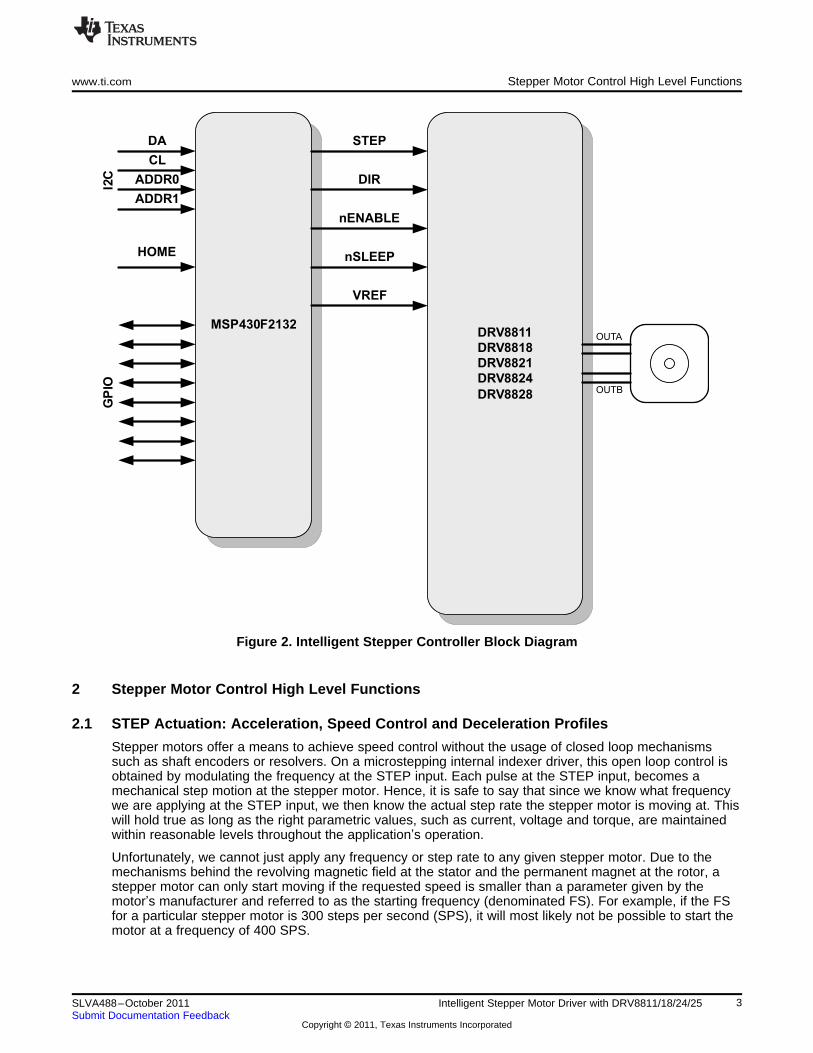
MSP430F2132DRV8811
DRV8818
DRV8821
DRV8824
DRV8828
STEP
DIR
nENABLE
DA
CL
HOME
GP
IO
ADDR0
ADDR1
I2C
nSLEEP
OUTA
OUTB
VREF
www.ti.com Stepper Motor Control High Level Functions
Figure 2. Intelligent Stepper Controller Block Diagram
2 Stepper Motor Control High Level Functions
2.1 STEP Actuation: Acceleration, Speed Control and Deceleration Profiles
Stepper motors offer a means to achieve speed control without the usage of closed loop mechanismssuch as shaft encoders or resolvers. On a microstepping internal indexer driver, this open loop control isobtained by modulating the frequency at the STEP input. Each pulse at the STEP input, becomes amechanical step motion at the stepper motor. Hence, it is safe to say that since we know what frequencywe are applying at the STEP input, we then know the actual step rate the stepper motor is moving at. Thiswill hold true as long as the right parametric values, such as current, voltage and torque, are maintainedwithin reasonable levels throughout the application’s operation.
Unfortunately, we cannot just apply any frequency or step rate to any given stepper motor. Due to themechanisms behind the revolving magnetic field at the stator and the permanent magnet at the rotor, astepper motor can only start moving if the requested speed is smaller than a parameter given by themotor’s manufacturer and referred to as the starting frequency (denominated FS). For example, if the FSfor a particular stepper motor is 300 steps per second (SPS), it will most likely not be possible to start themotor at a frequency of 400 SPS.
3SLVA488–October 2011 Intelligent Stepper Motor Driver with DRV8811/18/24/25Submit Documentation Feedback
Copyright © 2011, Texas Instruments Incorporated
Time (s)
Mo
tor
Sp
ee
d(S
PS
)
Desired Speed (SPS)
Starting Speed (SPS)
Stopping Speed (SPS)Acceleration Rate (SPSPS)
Deceleration Rate (SPSPS)
Stepper Motor Control High Level Functions www.ti.com
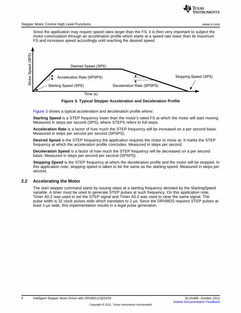
Since the application may require speed rates larger than the FS, it is then very important to subject themotor commutation through an acceleration profile which starts at a speed rate lower than its maximumFS and increases speed accordingly until reaching the desired speed.
Figure 3. Typical Stepper Acceleration and Deceleration Profile
Figure 3 shows a typical acceleration and deceleration profile where:
Starting Speed is a STEP frequency lower than the motor’s rated FS at which the motor will start moving.Measured in steps per second (SPS), where STEPS refers to full steps.
Acceleration Rate is a factor of how much the STEP frequency will be increased on a per second basis.Measured in steps per second per second (SPSPS).
Desired Speed is the STEP frequency the application requires the motor to move at. It marks the STEPfrequency at which the acceleration profile concludes. Measured in steps per second.
Deceleration Speed is a factor of how much the STEP frequency will be decreased on a per secondbasis. Measured in steps per second per second (SPSPS).
Stopping Speed is the STEP frequency at which the deceleration profile and the motor will be stopped. Inthis application note, stopping speed is taken to be the same as the starting speed. Measured in steps persecond.
2.2 Accelerating the Motor
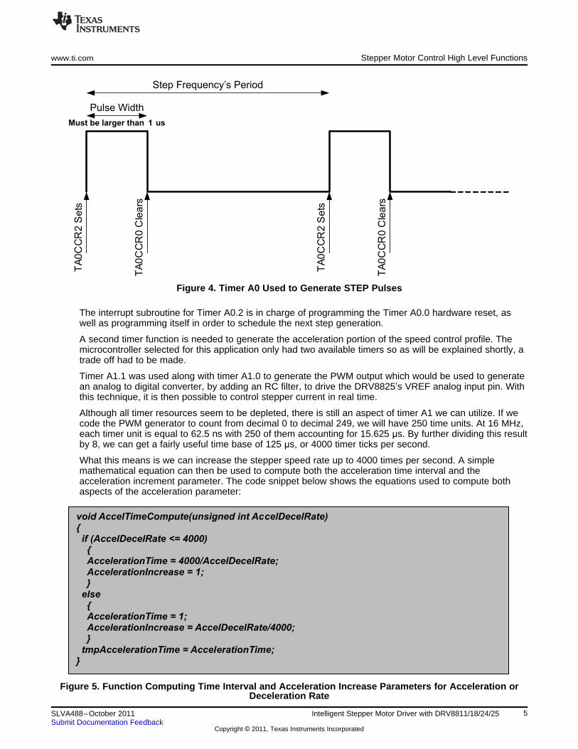
The start stepper command starts by issuing steps at a starting frequency denoted by the StartingSpeedvariable. A timer must be used to generate STEP pulses at such frequency. On this application note,Timer A0.2 was used to set the STEP signal and Timer A0.0 was used to clear the same signal. Thepulse width is 32 clock pulses wide which translates to 2 µs. Since the DRV8825 requires STEP pulses atleast 1-µs wide, this implementation results in a legal pulse generation.
4 Intelligent Stepper Motor Driver with DRV8811/18/24/25 SLVA488–October 2011Submit Documentation Feedback
Copyright © 2011, Texas Instruments Incorporated
Step Frequency’s Period
Pulse Width
Must be larger than 1 us
TA
0C
CR
2S
ets
TA
0C
CR
0C
lea
rs
TA
0C
CR
2S
ets
TA
0C
CR
0C
lea
rs
void AccelTimeCompute(unsigned int AccelDecelRate){if (AccelDecelRate <= 4000){AccelerationTime = 4000/AccelDecelRate;AccelerationIncrease = 1;}
else{AccelerationTime = 1;AccelerationIncrease = AccelDecelRate/4000;}
tmpAccelerationTime = AccelerationTime;}
www.ti.com Stepper Motor Control High Level Functions
Figure 4. Timer A0 Used to Generate STEP Pulses
The interrupt subroutine for Timer A0.2 is in charge of programming the Timer A0.0 hardware reset, aswell as programming itself in order to schedule the next step generation.
A second timer function is needed to generate the acceleration portion of the speed control profile. Themicrocontroller selected for this application only had two available timers so as will be explained shortly, atrade off had to be made.
Timer A1.1 was used along with timer A1.0 to generate the PWM output which would be used to generatean analog to digital converter, by adding an RC filter, to drive the DRV8825’s VREF analog input pin. Withthis technique, it is then possible to control stepper current in real time.
Although all timer resources seem to be depleted, there is still an aspect of timer A1 we can utilize. If wecode the PWM generator to count from decimal 0 to decimal 249, we will have 250 time units. At 16 MHz,each timer unit is equal to 62.5 ns with 250 of them accounting for 15.625 µs. By further dividing this resultby 8, we can get a fairly useful time base of 125 µs, or 4000 timer ticks per second.
What this means is we can increase the stepper speed rate up to 4000 times per second. A simplemathematical equation can then be used to compute both the acceleration time interval and theacceleration increment parameter. The code snippet below shows the equations used to compute bothaspects of the acceleration parameter:
Figure 5. Function Computing Time Interval and Acceleration Increase Parameters for Acceleration orDeceleration Rate
5SLVA488–October 2011 Intelligent Stepper Motor Driver with DRV8811/18/24/25Submit Documentation Feedback
Copyright © 2011, Texas Instruments Incorporated

Init H Bridges and VariablesTimer A0.1 = Start Speed
Start Stepper?
YES
NO
Accel TimeComplete?
YES
Timer A0.1Count Accel Time Interval
NO
Compute Acceleration Rateand Acceleration Time
Start Acceleration Engine
Stepper Speed+= AccelRate
START
Stepper Speed >=
Desired Speed?
NO
Stepper Speed= Desired SpeedDisable Acceleration Engine
END
Stepper Motor Control High Level Functions www.ti.com
Figure 6 shows the flowchart of the state machine in charge of coordinating the acceleration. As can beseen, the command to start the motor will configure all the parameters required for motion, including thecall to the AccelTimeCompute function.
Figure 6. Stepper Speed Acceleration Flowchart
The actual speed modification takes place inside the AccelDecel function which gets called from within themain execution which is in turn enabled within the timer A1.0 interrupt service routine (ISR). It is importantfor the AccelDecel function not to be called from within inside the ISR as this impacts real time operation.Instead, inside the ISR the microcontroller sleep mode is disabled, which allows execution to resume fromthe main loop.
6 Intelligent Stepper Motor Driver with DRV8811/18/24/25 SLVA488–October 2011Submit Documentation Feedback
Copyright © 2011, Texas Instruments Incorporated
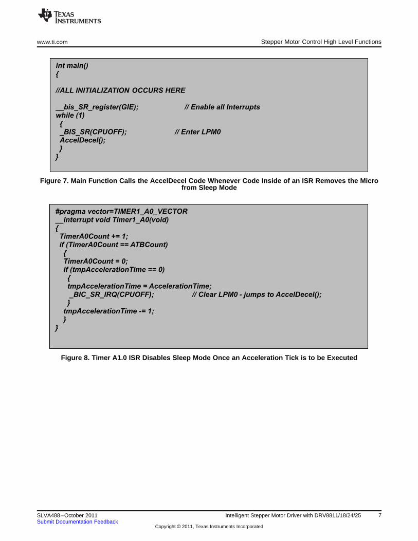
int main(){
//ALL INITIALIZATION OCCURS HERE
__bis_SR_register(GIE); // Enable all Interruptswhile (1){_BIS_SR(CPUOFF); // Enter LPM0AccelDecel();}
}
#pragma vector=TIMER1_A0_VECTOR__interrupt void Timer1_A0(void){TimerA0Count += 1;if (TimerA0Count == ATBCount){TimerA0Count = 0;if (tmpAccelerationTime == 0){tmpAccelerationTime = AccelerationTime;_BIC_SR_IRQ(CPUOFF); // Clear LPM0 - jumps to AccelDecel();}
tmpAccelerationTime -= 1;}
}
www.ti.com Stepper Motor Control High Level Functions
Figure 7. Main Function Calls the AccelDecel Code Whenever Code Inside of an ISR Removes the Microfrom Sleep Mode
Figure 8. Timer A1.0 ISR Disables Sleep Mode Once an Acceleration Tick is to be Executed
7SLVA488–October 2011 Intelligent Stepper Motor Driver with DRV8811/18/24/25Submit Documentation Feedback
Copyright © 2011, Texas Instruments Incorporated

void AccelDecel(void){
switch (AccelerationState){case (NOACC):break;
case (ACCEL):ActualStepperSpeed += AccelerationIncrease;if (ActualStepperSpeed >= DesiredStepperSpeed){ActualStepperSpeed = DesiredStepperSpeed;AccelerationState = NOACC;TA1CCTL0 &= ~CCIE; //DISABLE 250 us coordinator interrupt on TA1.0
}SpeedCompute(ActualStepperSpeed);
break;case (DECEL):ActualStepperSpeed -= AccelerationIncrease;if (ActualStepperSpeed <= DesiredStepperSpeed){ActualStepperSpeed = DesiredStepperSpeed;AccelerationState = NOACC;TA1CCTL0 &= ~CCIE; //DISABLE 250 us coordinator interrupt on TA1.0
}SpeedCompute(ActualStepperSpeed);
break;case (STOP):ActualStepperSpeed -= AccelerationIncrease;if (ActualStepperSpeed <= StartStepperSpeed){ActualStepperSpeed = StartStepperSpeed;AccelerationState = NOACC;TA1CCTL0 &= ~CCIE; //DISABLE 250 us coordinator interrupt on TA1.0ExecutedSteps = NumberOfSteps - 1;
}SpeedCompute(ActualStepperSpeed);break;
}}
Stepper Motor Control High Level Functions www.ti.com
Figure 9. AccelDecel Function is State Machine Code in Charge of Modifying Stepper Speed According toProgrammed Acceleration or Deceleration Profile
2.3 Stepper Speed
Stepper speed is carefully controlled by using Timer A1.0 and A1.2 as detailed previously. How the timeris being clocked is important to understand, as the 16- bit timer by itself is not capable of reproducing allthe possible speeds applications around this topology may try to run at. For example, while the Timer A1is being clocked at 16 MHz, fast stepping rates are easily obtained, while slow speeds cannot begenerated.
8 Intelligent Stepper Motor Driver with DRV8811/18/24/25 SLVA488–October 2011Submit Documentation Feedback
Copyright © 2011, Texas Instruments Incorporated
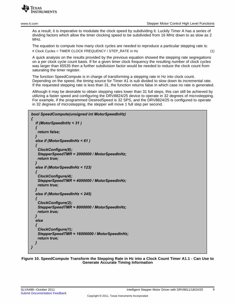
bool SpeedCompute(unsigned int MotorSpeedInHz){
if (MotorSpeedInHz < 31 ){
return false;}else if (MotorSpeedInHz < 61 ){
ClockConfigure(8);StepperSpeedTMR = 2000000 / MotorSpeedInHz;return true;
}else if (MotorSpeedInHz < 123){
ClockConfigure(4);StepperSpeedTMR = 4000000 / MotorSpeedInHz;return true;
}else if (MotorSpeedInHz < 245){
ClockConfigure(2);StepperSpeedTMR = 8000000 / MotorSpeedInHz;return true;
}else{
ClockConfigure(1);StepperSpeedTMR = 16000000 / MotorSpeedInHz;return true;
}}
www.ti.com Stepper Motor Control High Level Functions
As a result, it is imperative to modulate the clock speed by subdividing it. Luckily Timer A has a series ofdividing factors which allow the timer clocking speed to be subdivided from 16 MHz down to as slow as 2MHz.
The equation to compute how many clock cycles are needed to reproduce a particular stepping rate is:# Clock Cycles = TIMER CLOCK FREQUENCY / STEP_RATE in Hz (1)
A quick analysis on the results provided by the previous equation showed the stepping rate segregationson a per clock cycle count basis. If for a given timer clock frequency the resulting number of clock cycleswas larger than 65535 then a further subdivision factor would be needed to reduce the clock count fromsaturating the timer register.
The function SpeedCompute is in charge of transforming a stepping rate in Hz into clock count.Depending on the speed, the timing source for Timer A1 is sub divided to slow down its incremental rate.If the requested stepping rate is less than 31, the function returns false in which case no rate is generated.
Although it may be desirable to obtain stepping rates lower than 31 full steps, this can still be achieved byutilizing a faster speed and configuring the DRV8824/25 device to operate in 32 degrees of microstepping.For example, if the programmed DesiredSpeed is 32 SPS, and the DRV8824/25 is configured to operatein 32 degrees of microstepping, the stepper will move 1 full step per second.
Figure 10. SpeedCompute Transform the Stepping Rate in Hz into a Clock Count Timer A1.1 - Can Use toGenerate Accurate Timing Information
9SLVA488–October 2011 Intelligent Stepper Motor Driver with DRV8811/18/24/25Submit Documentation Feedback
Copyright © 2011, Texas Instruments Incorporated

void ClockConfigure(char Divider){int tempTA0CTL;tempTA0CTL = TA0CTL;switch (Divider){case 1:tempTA0CTL &= ~( BIT7 + BIT6);break;
case 2:tempTA0CTL &= ~( BIT7 + BIT6);tempTA0CTL |= TA0_ID_DIV2;break;
case 4:tempTA0CTL &= ~( BIT7 + BIT6);tempTA0CTL |= TA0_ID_DIV4;break;
case 8:tempTA0CTL &= ~( BIT7 + BIT6);tempTA0CTL |= TA0_ID_DIV8;break;}TA0CTL = tempTA0CTL;
}
Stepper Motor Control High Level Functions www.ti.com
Figure 11. Function ClockConfigure is Called Within the SpeedCompute Function to Modify the DividerAffecting Timer A1 Clock Speed
The functions SpeedCompute and ClockConfigure are called to set the StartSpeed, to set the new stepperspeed on a per acceleration click occurrence and then when the DesiredSpeed is met. Once theprogrammed DesiredSpeed target is reached the stepper motor maintains said speed until a decelerationprofile is commanded.
2.4 Decelerating the Motor
The concept of a deceleration profile the motor is virtually identical to the acceleration profileimplementation except that instead of increasing stepper speed, speed is decreased.
There are two instances in which a deceleration profile may be employed: during SpeedUpdate or duringStepperStop commands. In this implementation, the stepper deceleration profile is finished either whenthe start speed is reached or when the programmed number of steps is executed.
Also, it was chosen for the deceleration rate to hold a different memory location such that a non symmetricacceleration/deceleration profile, such as the one portrayed in Figure 3, could be employed.
The SpeedCompute and ClockConfigure are used in the same fashion as they were used during theacceleration portion of the motion control profile. However, the state machine, or the AccelDecel function,is configured to execute the DECEL portion of code.
2.5 Speed Change
During run time, it is possible to change the speed and incur in further acceleration or deceleration asdeemed by the application. When the command SpeedUpdate is issued, the firmware checks to seewhether the new DesiredSpeed is larger or smaller than the ActualStepperSpeed. The result of thisoperation configures the Acceleration Deceleration engine accordingly.
10 Intelligent Stepper Motor Driver with DRV8811/18/24/25 SLVA488–October 2011Submit Documentation Feedback
Copyright © 2011, Texas Instruments Incorporated
www.ti.com Stepper Motor Control High Level Functions
2.6 Position Control: Number Of Steps
The closed loop capabilities of a stepper are not limited to accurately controlling the speed. Since inessence the controller is counting the very same steps which are being generated, knowledge of stepposition is continuously being updated. Every time a step is executed, the variable StepPosition is updatedaccording to step rotation direction. For example, if the motor is rotating clockwise (DIR = HI), theStepPosition variable is incremented, whereas if the motor is rotating counterclockwise (DIR = LO), thenthe StepPosition variable is decremented.
NOTE: The notions of motor rotation as clockwise or counterclockwise are directly dependent tohow the motor was wired and the motor itself.
The variable StepPosition can be read in real time to obtain information as to where the motor is at anygiven point in time.
On this application note, however, the controller is always operating in Position Control mode. Thevariable NumberOfSteps is programmed to hold the entire number of steps which will be executed. Sincethis is a 32-bit variable, the total number of steps could be a significantly large number, in which case themotor would in essence be operating in free running mode. However, if the NumberOfSteps count issmall, then the motor will stop once the total NumbeOfSteps have been executed.
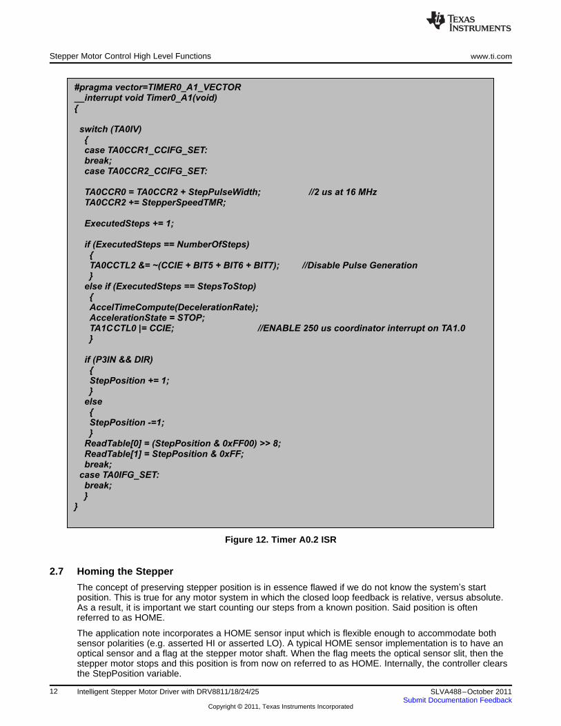
The previous mechanism is achieved by counting how many steps have been executed and comparingthis number to the NumberOfSteps command. This is taken care of on the Timer A0.2 ISR as shown inFigure 12.
Notice this ISR is in charge of a few tasks we have described earlier and which are of crucial importanceto generating accurate stepping information. These tasks are:
1. Generation of the STEP pulse by configuring when the STEP clear takes place. Timer A0.0 is incharge of returning the STEP signal to LO.
2. Configuring the TIMERA0.2 to generate the next step according to the current step rate, orStepperSpeedTMR, which is the timer equivalent of the current rate in Hz.
3. Determining whether the current generated step is the last step to execute. This happens whenExecutedSteps is equal to NumberOfSteps.
4. If the current generated step is equal to StepsToStop value, then the engine is commanded to start adeceleration profile.
5. Update StepPosition according to motor direction.
11SLVA488–October 2011 Intelligent Stepper Motor Driver with DRV8811/18/24/25Submit Documentation Feedback
Copyright © 2011, Texas Instruments Incorporated
#pragma vector=TIMER0_A1_VECTOR__interrupt void Timer0_A1(void){
switch (TA0IV){case TA0CCR1_CCIFG_SET:break;case TA0CCR2_CCIFG_SET:
TA0CCR0 = TA0CCR2 + StepPulseWidth; //2 us at 16 MHzTA0CCR2 += StepperSpeedTMR;
ExecutedSteps += 1;
if (ExecutedSteps == NumberOfSteps){TA0CCTL2 &= ~(CCIE + BIT5 + BIT6 + BIT7); //Disable Pulse Generation}
else if (ExecutedSteps == StepsToStop){AccelTimeCompute(DecelerationRate);AccelerationState = STOP;TA1CCTL0 |= CCIE; //ENABLE 250 us coordinator interrupt on TA1.0}
if (P3IN && DIR){StepPosition += 1;}
else{StepPosition -=1;}
ReadTable[0] = (StepPosition & 0xFF00) >> 8;ReadTable[1] = StepPosition & 0xFF;break;
case TA0IFG_SET:break;}
}
Stepper Motor Control High Level Functions www.ti.com
Figure 12. Timer A0.2 ISR
2.7 Homing the Stepper
The concept of preserving stepper position is in essence flawed if we do not know the system’s startposition. This is true for any motor system in which the closed loop feedback is relative, versus absolute.As a result, it is important we start counting our steps from a known position. Said position is oftenreferred to as HOME.
The application note incorporates a HOME sensor input which is flexible enough to accommodate bothsensor polarities (e.g. asserted HI or asserted LO). A typical HOME sensor implementation is to have anoptical sensor and a flag at the stepper motor shaft. When the flag meets the optical sensor slit, then thestepper motor stops and this position is from now on referred to as HOME. Internally, the controller clearsthe StepPosition variable.
12 Intelligent Stepper Motor Driver with DRV8811/18/24/25 SLVA488–October 2011Submit Documentation Feedback
Copyright © 2011, Texas Instruments Incorporated

#pragma vector=PORT1_VECTOR__interrupt void PORT1_Change(void){if (P1IFG && HOMEIN){P1IE = 0;P1IFG = 0;TA0CCTL2 &= ~(CCIE + BIT5 + BIT6 + BIT7);StepPosition = 0;
}}
www.ti.com I2C Protocol and Communications Engine
Since the motor can be started at any given position, the HOME sensor could be found to be at eitherstate. Hence, initially, the state is to be considered unknown. The typical homing implementation calls fora transition from HI to LO or a transition from LO to HI as chosen by the application.
In order to easily capture the chosen transition, the HOME sensor was allocated to a GPIO pin with a PinOn Change Interrupt. Since the pin can be configured to raise the ISR flag either with a rising or a fallingedge, we can capture on either edge. Whereas the typical polling function would require some sort of astate machine to filter out the wrong transition, this hardware interrupt works exceptionally well, renderingthe amount of code to be considerably tiny.Figure 13 shows the ISR for the PORT1 Pin On ChangeInterrupt vector. The reader will notice this code is in charge of clearing the StepPosition variable, as wellas stopping the motor.
Figure 13. Port 1 Pin On Change Interrupt Service Routine
3 I2C Protocol and Communications Engine
In order to program the device parameters and the stepper motion engine profiles, an I2C protocol waschosen. The way it was designed, up to four controllers can be cascaded with only two communicationlines and two address selector lines.
The I2C protocol is the typical three byte packet where the first byte is the slave address, the second byteis the register address and the third byte is the data. There are 21 possible address register which can beaccessed.
13SLVA488–October 2011 Intelligent Stepper Motor Driver with DRV8811/18/24/25Submit Documentation Feedback
Copyright © 2011, Texas Instruments Incorporated

Number Of Steps
Number Of Steps
Number Of Steps1
Number Of Steps0
StepsToStop
StepsToStop
StepsToStop1
StepsToStop0
StartSpeed1
StartSpeed0
Accel1
Accel0
DesiredSpeed1
DesiredSpeed0
Decel1
Decel0
GPIO CONFIG
Stepper Config
GPIO OUT
Current Duty Cycle
Start Stepper
0x00
0x01
0x02
0x03
0x04
0x05
0x06
0x07
0x08
0x09
0x0A
0x0B
0x0C
0x0D
0x0E
0x0F
0x10
0x11
0x12
0x13
0x14
Index PARAMETER TABLE
GPIO DIR 7
Bit 7 Bit 0
GPIO DIR 6 GPIO DIR 5 GPIO DIR 4 GPIO DIR 3 GPIO DIR 2 GPIO DIR 1 GPIO DIR 0
N/A
Bit 7 Bit 0
ENABLE MODE2 MODE1 MODE0 N/A N/A DIR
I2C Protocol and Communications Engine www.ti.com
Figure 14. Parameters Table
The variables residing on addresses 0x00 to 0x0F have been discussed on previous sections. The otheraddresses are a combination of parameters as well as actions.
3.1 GPIO CONFIG
Defines the GPIO direction, for the 8 GPIO pins 0 to 7, where a configuration of 0 denotes an input and aconfiguration of 1 denotes an output.
3.2 STEPPER CONFIG
Configures control signals for the stepper power stage. These register bits are directly mapped to thePower Stage hardware pins, so changing the state of any of these bits immediately changes therespective pin at the power stage input.
14 Intelligent Stepper Motor Driver with DRV8811/18/24/25 SLVA488–October 2011Submit Documentation Feedback
Copyright © 2011, Texas Instruments Incorporated
GPIO 7
Bit 7 Bit 0
GPIO 6 GPIO 5 GPIO 4 GPIO 3 GPIO 2 GPIO 1 GPIO 0
START ACCEL
START STEPPER
STOP STEPPER
CHANGE SPEED
HOME HI
HOME LO
0x00
0x01
0x02
0x03
0x04
0x05
OPCODE START STEPPER
www.ti.com I2C Protocol and Communications Engine
3.3 GPIO OUT
Those GPIO bits which were configured as outputs are configured when writing to this address. Note thatwriting to this address is equivalent to writing to the MSP430 PxOUT register so only bits which areconfigured to be outputs on their respective PxDIR register, will react accordingly. Those pins which areconfigured as inputs will still behave as inputs.
3.4 Current Duty Cycle
A register accepting a number from 0 to 249 which then becomes PWM output duty cycle. The currentcode does not check whether the written is equal or less than 249. Any number larger than 249 will yield a100% duty cycle PWM.
3.5 START STEPPER
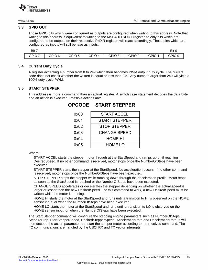
This address is more a command than an actual register. A switch case statement decodes the data byteand an action is executed. Possible actions are:
Where:START ACCEL starts the stepper motor through at the StartSpeed and ramps up until reachingDesiredSpeed. If no other command is received, motor stops once the NumberOfSteps have beenexecuted.START STEPPER starts the stepper at the StartSpeed. No acceleration occurs. If no other commandis received, motor stops once the NumberOfSteps have been executed.STOP STEPPER stops the stepper while ramping down through the deceleration profile. Motor stopsas soon as the StartSpeed is reached or the NumberOfSteps have been executed.CHANGE SPEED accelerates or decelerates the stepper depending on whether the actual speed islarger or lesser than the new DesiredSpeed. For this command to work, a new DesiredSpeed must bewritten while the motor is running.HOME HI starts the motor at the StartSpeed and runs until a transition to HI is observed on the HOMEsensor input, or when the NumberOfSteps have been executed.HOME LO starts the motor at the StartSpeed and runs until a transition to LO is observed on theHOME sensor input, or when the NumberOfSteps have been executed.
The Start Stepper command will configure the stepping engine parameters such as NumberOfSteps,StepsToStop, StartStepperSpeed, DesiredStepperSpeed, AccelerationRate and DecelerationRate. It willthen decode the action parameter and start the stepper motor according to the received command. TheI2C communications are handled by the USCI RX and TX vector interrupts.
15SLVA488–October 2011 Intelligent Stepper Motor Driver with DRV8811/18/24/25Submit Documentation Feedback
Copyright © 2011, Texas Instruments Incorporated
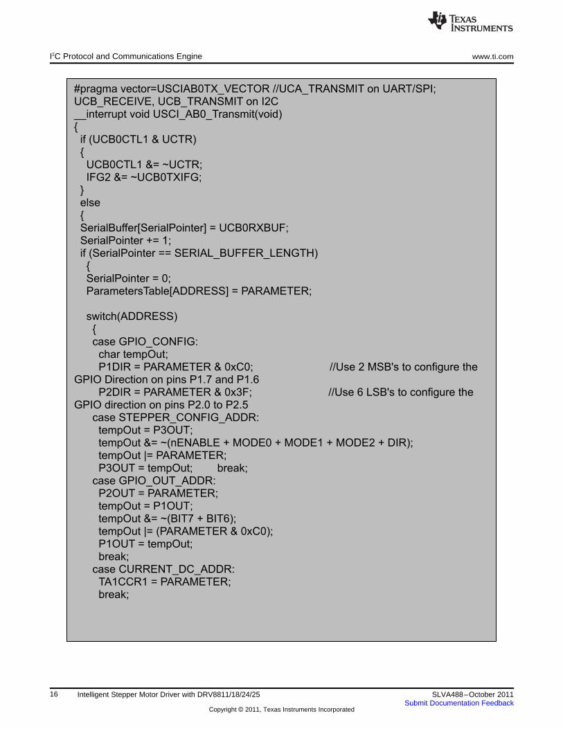
#pragma vector=USCIAB0TX_VECTOR //UCA_TRANSMIT on UART/SPI;UCB_RECEIVE, UCB_TRANSMIT on I2C__interrupt void USCI_AB0_Transmit(void){
if (UCB0CTL1 & UCTR){UCB0CTL1 &= ~UCTR;IFG2 &= ~UCB0TXIFG;
}else{SerialBuffer[SerialPointer] = UCB0RXBUF;SerialPointer += 1;if (SerialPointer == SERIAL_BUFFER_LENGTH){SerialPointer = 0;ParametersTable[ADDRESS] = PARAMETER;
switch(ADDRESS){case GPIO_CONFIG:
char tempOut;P1DIR = PARAMETER & 0xC0; //Use 2 MSB's to configure the
GPIO Direction on pins P1.7 and P1.6P2DIR = PARAMETER & 0x3F; //Use 6 LSB's to configure the
GPIO direction on pins P2.0 to P2.5case STEPPER_CONFIG_ADDR:tempOut = P3OUT;tempOut &= ~(nENABLE + MODE0 + MODE1 + MODE2 + DIR);tempOut |= PARAMETER;P3OUT = tempOut; break;
case GPIO_OUT_ADDR:P2OUT = PARAMETER;tempOut = P1OUT;tempOut &= ~(BIT7 + BIT6);tempOut |= (PARAMETER & 0xC0);P1OUT = tempOut;break;
case CURRENT_DC_ADDR:TA1CCR1 = PARAMETER;break;
I2C Protocol and Communications Engine www.ti.com
16 Intelligent Stepper Motor Driver with DRV8811/18/24/25 SLVA488–October 2011Submit Documentation Feedback
Copyright © 2011, Texas Instruments Incorporated

case START_STEPPER_ADDR:NumberOfSteps = (ParametersTable[NUMBER_OF_STEPS3_ADDR] << 8) +
(ParametersTable[NUMBER_OF_STEPS2_ADDR]);NumberOfSteps *= 65536;NumberOfSteps += (ParametersTable[NUMBER_OF_STEPS1_ADDR] << 8) +
ParametersTable[NUMBER_OF_STEPS0_ADDR];ExecutedSteps = 0;
StepsToStop = (ParametersTable[STEPS_TO_STOP3_ADDR] << 8) +(ParametersTable[STEPS_TO_STOP2_ADDR]);
StepsToStop *= 65536;StepsToStop += (ParametersTable[STEPS_TO_STOP1_ADDR] << 8) +
ParametersTable[STEPS_TO_STOP0_ADDR];
StartStepperSpeed = (ParametersTable[START_SPEED1_ADDR] << 8) +ParametersTable[START_SPEED0_ADDR];
DesiredStepperSpeed = (ParametersTable[DESIRED_SPEED1_ADDR] << 8) +ParametersTable[DESIRED_SPEED0_ADDR];
AccelerationRate = (ParametersTable[ACCEL1_ADDR] << 8) +ParametersTable[ACCEL0_ADDR];
DecelerationRate = (ParametersTable[DECEL1_ADDR] << 8) +ParametersTable[DECEL0_ADDR];
www.ti.com I2C Protocol and Communications Engine
17SLVA488–October 2011 Intelligent Stepper Motor Driver with DRV8811/18/24/25Submit Documentation Feedback
Copyright © 2011, Texas Instruments Incorporated
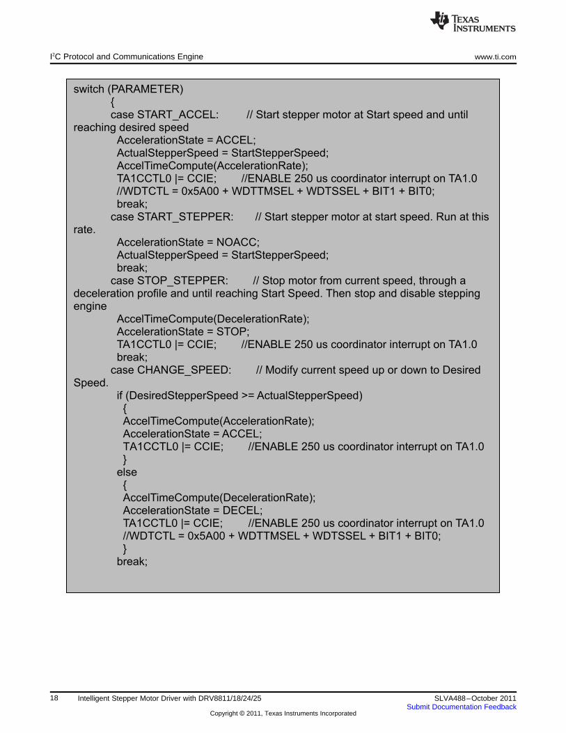
switch (PARAMETER){case START_ACCEL: // Start stepper motor at Start speed and until
reaching desired speedAccelerationState = ACCEL;ActualStepperSpeed = StartStepperSpeed;AccelTimeCompute(AccelerationRate);TA1CCTL0 |= CCIE; //ENABLE 250 us coordinator interrupt on TA1.0//WDTCTL = 0x5A00 + WDTTMSEL + WDTSSEL + BIT1 + BIT0;break;
case START_STEPPER: // Start stepper motor at start speed. Run at thisrate.
AccelerationState = NOACC;ActualStepperSpeed = StartStepperSpeed;break;
case STOP_STEPPER: // Stop motor from current speed, through adeceleration profile and until reaching Start Speed. Then stop and disable steppingengine
AccelTimeCompute(DecelerationRate);AccelerationState = STOP;TA1CCTL0 |= CCIE; //ENABLE 250 us coordinator interrupt on TA1.0break;
case CHANGE_SPEED: // Modify current speed up or down to DesiredSpeed.
if (DesiredStepperSpeed >= ActualStepperSpeed){AccelTimeCompute(AccelerationRate);AccelerationState = ACCEL;TA1CCTL0 |= CCIE; //ENABLE 250 us coordinator interrupt on TA1.0}
else{AccelTimeCompute(DecelerationRate);AccelerationState = DECEL;TA1CCTL0 |= CCIE; //ENABLE 250 us coordinator interrupt on TA1.0//WDTCTL = 0x5A00 + WDTTMSEL + WDTSSEL + BIT1 + BIT0;}
break;
I2C Protocol and Communications Engine www.ti.com
18 Intelligent Stepper Motor Driver with DRV8811/18/24/25 SLVA488–October 2011Submit Documentation Feedback
Copyright © 2011, Texas Instruments Incorporated
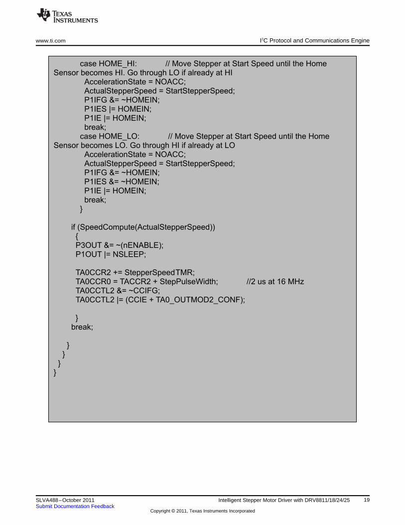
case HOME_HI: // Move Stepper at Start Speed until the HomeSensor becomes HI. Go through LO if already at HI
AccelerationState = NOACC;ActualStepperSpeed = StartStepperSpeed;P1IFG &= ~HOMEIN;P1IES |= HOMEIN;P1IE |= HOMEIN;break;
case HOME_LO: // Move Stepper at Start Speed until the HomeSensor becomes LO. Go through HI if already at LO
AccelerationState = NOACC;ActualStepperSpeed = StartStepperSpeed;P1IFG &= ~HOMEIN;P1IES &= ~HOMEIN;P1IE |= HOMEIN;break;
}
if (SpeedCompute(ActualStepperSpeed)){P3OUT &= ~(nENABLE);P1OUT |= NSLEEP;
TA0CCR2 += StepperSpeedTMR;TA0CCR0 = TACCR2 + StepPulseWidth; //2 us at 16 MHzTA0CCTL2 &= ~CCIFG;TA0CCTL2 |= (CCIE + TA0_OUTMOD2_CONF);
}break;
}}
}}
www.ti.com I2C Protocol and Communications Engine
19SLVA488–October 2011 Intelligent Stepper Motor Driver with DRV8811/18/24/25Submit Documentation Feedback
Copyright © 2011, Texas Instruments Incorporated

Application Schematic www.ti.com
4 Application Schematic
The following page contains the MSP430 and DRV8811/18/24/25 combo board schematic.
20 Intelligent Stepper Motor Driver with DRV8811/18/24/25 SLVA488–October 2011Submit Documentation Feedback
Copyright © 2011, Texas Instruments Incorporated

1
1
2
2
3
3
4
4
5
5
6
6
D D
C C
B B
A A
1 23 45 67 89 1011 1213 14
J
1
J
TAG
GND
V3p3
SBWTCK
V3p3
GND
0.1uFC1
nSLEEP
STEP
1
TP1VM
VM
1
TP2G
ND
GND
1
TP3V
3P3
0.1uFC5
1234
J
5
S
tepper
AOUT1A
OUT2
C3 0.01uF CP1C
P2
0
.1uF
C6
VCP0
.1uFC4
VM
AOUT1
A
OUT2I
SENA
D
ECAYn
FAULTn
SLEEP
V
3P3OUT
B
OUT1
B
OUT2I
SENB
DIRn
ENABLES
TEP
MD0MD1MD2
.47uFC7
12
J
2
V
M
1234
J
4
S
tepper
A
OUT1A
OUT2
3.3KR7
.
2
R6
.
2
R5
100uF
C
2
3.3K
R
1
D1
V
M
VM
BOUT1B
OUT2
B
OUT1B
OUT2
GN
D0
OUT1
FB2
NC3
GND4
EN5
NC6
NC7
IN8
U
3
TPS79801
10 uF
C9
VM
61.9K
R
11
39K
R
12
V3p3
TST/SBW1
DVCC2
P2.53
DVSS4
P2.7/ XOUT5
P2.6 / XIN6
RST7
P2.08
P2.19
P2.21
0P3.0
11
P3.11
2P3.2
13
P3.31
4 P3.4/TX15
P3.5/RX16
P3.6/TA1.017
P3.7/TA1.118
P2.31
9P2.4
20
P1.0/TACLK21
P1.1/TA0.022
P1.2/TA0.123
P1.3/TA0.224
P1.4/TCK25
P1.5/TMS26
P1.6 TCLK27
P1.7/TDI28
U1
MSP430F2132
CP11
CP22
VCP3
VMA4
AOUT15
ISENA6
AOUT27
BOUT28
ISENB9
BOUT11
0VMB
11
VREF1
2VREF
13
GND1
4 V3P3OUT1
5nRESET
16
nSLEEP1
7nFAULT
18
DECAY1
9DIR
20
nENABLE2
1STEP
22NC
23
MODE02
4MODE1
25
MODE22
6nHOME
27
GND2
8
GN
D0
U2
D
RV8825
M
D0 MD1M
D2
G
PIO0G
PIO1G
PIO2 GPIO3G
PIO4
G
PIO5
D
IRS
DAS
CL
V
REF_PWMn
ENABLE
H
OMES
BW_
TDOISBWTCK
SBW_TDOI
GPIO7GPIO6
330R2
V3p3
V3p3
12
J
6
I
2C
SDAS
CL
12345678910
J
9
G
PIO
V3p3
GPIO0G
PIO1G
PIO2G
PIO3G
PIO4G
PIO5G
PIO6G
PIO7
VREF_PWM
0.01uF
C8
5.1KR8
3
.3K
R3
123
J
3
H
OME
V3p3
HOME
A
DR0A
DR1
12Y1
12
J
MP1
A
DR0
A
DR0 ADR1
3.3KR9
V3p3
12
J
MP2
A
DR0
3.3KR10
V3p3
3.3KR4
nFAULT
TL1
DRV8825Combo
3.3K
R13
www.ti.com Application Schematic
21SLVA488–October 2011 Intelligent Stepper Motor Driver with DRV8811/18/24/25Submit Documentation Feedback
Copyright © 2011, Texas Instruments Incorporated

IMPORTANT NOTICE
Texas Instruments Incorporated and its subsidiaries (TI) reserve the right to make corrections, modifications, enhancements, improvements,and other changes to its products and services at any time and to discontinue any product or service without notice. Customers shouldobtain the latest relevant information before placing orders and should verify that such information is current and complete. All products aresold subject to TI’s terms and conditions of sale supplied at the time of order acknowledgment.
TI warrants performance of its hardware products to the specifications applicable at the time of sale in accordance with TI’s standardwarranty. Testing and other quality control techniques are used to the extent TI deems necessary to support this warranty. Except wheremandated by government requirements, testing of all parameters of each product is not necessarily performed.
TI assumes no liability for applications assistance or customer product design. Customers are responsible for their products andapplications using TI components. To minimize the risks associated with customer products and applications, customers should provideadequate design and operating safeguards.
TI does not warrant or represent that any license, either express or implied, is granted under any TI patent right, copyright, mask work right,or other TI intellectual property right relating to any combination, machine, or process in which TI products or services are used. Informationpublished by TI regarding third-party products or services does not constitute a license from TI to use such products or services or awarranty or endorsement thereof. Use of such information may require a license from a third party under the patents or other intellectualproperty of the third party, or a license from TI under the patents or other intellectual property of TI.
Reproduction of TI information in TI data books or data sheets is permissible only if reproduction is without alteration and is accompaniedby all associated warranties, conditions, limitations, and notices. Reproduction of this information with alteration is an unfair and deceptivebusiness practice. TI is not responsible or liable for such altered documentation. Information of third parties may be subject to additionalrestrictions.
Resale of TI products or services with statements different from or beyond the parameters stated by TI for that product or service voids allexpress and any implied warranties for the associated TI product or service and is an unfair and deceptive business practice. TI is notresponsible or liable for any such statements.
TI products are not authorized for use in safety-critical applications (such as life support) where a failure of the TI product would reasonablybe expected to cause severe personal injury or death, unless officers of the parties have executed an agreement specifically governingsuch use. Buyers represent that they have all necessary expertise in the safety and regulatory ramifications of their applications, andacknowledge and agree that they are solely responsible for all legal, regulatory and safety-related requirements concerning their productsand any use of TI products in such safety-critical applications, notwithstanding any applications-related information or support that may beprovided by TI. Further, Buyers must fully indemnify TI and its representatives against any damages arising out of the use of TI products insuch safety-critical applications.
TI products are neither designed nor intended for use in military/aerospace applications or environments unless the TI products arespecifically designated by TI as military-grade or "enhanced plastic." Only products designated by TI as military-grade meet militaryspecifications. Buyers acknowledge and agree that any such use of TI products which TI has not designated as military-grade is solely atthe Buyer's risk, and that they are solely responsible for compliance with all legal and regulatory requirements in connection with such use.
TI products are neither designed nor intended for use in automotive applications or environments unless the specific TI products aredesignated by TI as compliant with ISO/TS 16949 requirements. Buyers acknowledge and agree that, if they use any non-designatedproducts in automotive applications, TI will not be responsible for any failure to meet such requirements.
Following are URLs where you can obtain information on other Texas Instruments products and application solutions:
Products Applications
Audio www.ti.com/audio Communications and Telecom www.ti.com/communications
Amplifiers amplifier.ti.com Computers and Peripherals www.ti.com/computers
Data Converters dataconverter.ti.com Consumer Electronics www.ti.com/consumer-apps
DLP® Products www.dlp.com Energy and Lighting www.ti.com/energy
DSP dsp.ti.com Industrial www.ti.com/industrial
Clocks and Timers www.ti.com/clocks Medical www.ti.com/medical
Interface interface.ti.com Security www.ti.com/security
Logic logic.ti.com Space, Avionics and Defense www.ti.com/space-avionics-defense
Power Mgmt power.ti.com Transportation and Automotive www.ti.com/automotive
Microcontrollers microcontroller.ti.com Video and Imaging www.ti.com/video
RFID www.ti-rfid.com
OMAP Mobile Processors www.ti.com/omap
Wireless Connectivity www.ti.com/wirelessconnectivity
TI E2E Community Home Page e2e.ti.com
Mailing Address: Texas Instruments, Post Office Box 655303, Dallas, Texas 75265Copyright © 2011, Texas Instruments Incorporated