Intelligent Energy – Europe SAVE, ALTENER, STEER, C … · engineers and ventilation...
45
Grant agreement no: EIE/06/063/SI2.448101 Project acronym: Building Advent Building AdVanced Ventilation Technological examples to demonstrate materialised energy savings for acceptable indoor air quality and thermal comfort in different European climatic conditions Intelligent Energy – Europe (IEE) SAVE Key Action Key action: To produce case studies of 18 European buildings that incorporate successful low energy ventilation techniques and widely disseminate this information to engineers and architects in order to increase the use of low energy ventilation techniques. Final Publishable Report (PR) Period covered: from 1/2/07 to 31/7/09 Due date: 30/8/09 Start date of the action: 1/2/07 Duration: 30 months End date of the action: 31/7/09 A. J. Cripps (Supported by G.Susman), Buro Happold, [email protected] , 0044 20 7927 9700 Project website: http://www.buildingadvent.com/
Transcript of Intelligent Energy – Europe SAVE, ALTENER, STEER, C … · engineers and ventilation...
Grant agreement no: EIE/06/063/SI2.448101
Project acronym: Building Advent
Building AdVanced Ventilation Technological examples to demonstrate materialised energy savings for acceptable indoor air quality and thermal comfort in different European climatic conditions Intelligent Energy – Europe (IEE) SAVE Key Action Key action: To produce case studies of 18 European buildings that incorporate successful low energy ventilation techniques and widely disseminate this information to engineers and architects in order to increase the use of low energy ventilation techniques.
Final Publishable Report (PR)
Period covered: from 1/2/07 to 31/7/09 Due date: 30/8/09 Start date of the action: 1/2/07 Duration: 30 months End date of the action: 31/7/09 A. J. Cripps (Supported by G.Susman), Buro Happold, [email protected], 0044 20 7927 9700 Project website: http://www.buildingadvent.com/
Intelligent Energy – Europe SAVE, ALTENER, STEER, COOPENER, Horizontal Key Actions
Final Publishable Report EIE/06/063/SI2.448101 – Building AdVent Page 1 of 44
Table of Contents
1. Summary............................................................................................................... 2 1.1 Objectives of the action ................................................................................. 2 1.2 Achievements................................................................................................ 2 1.3 Summary of this report ..................................................................................3
2. Introduction: What is low energy ventilation? ....................................................... 4 3. Building Selection................................................................................................. 6
3.1 Climates.............................................................................................................. 6 3.2 Selected Buildings............................................................................................... 9
4. Occupant comfort................................................................................................ 24 5. Building measurements ....................................................................................... 28 6. Barriers to use ..................................................................................................... 33 7. Communication................................................................................................... 34 Acknowledgements..................................................................................................... 44

Intelligent Energy – Europe SAVE, ALTENER, STEER, COOPENER, Horizontal Key Actions
Final Publishable Report EIE/06/063/SI2.448101 – Building AdVent Page 2 of 44
1. Summary 1.1 Objectives of the action
The main objective of this project is to support a reduction in the energy required to deliver ventilation effectively in non-domestic buildings. Development objectives include:
• Classification of existing building ventilation technologies as applied in built examples and collection of additional information on building performance.
• Identification of barriers for future application.
• Preparing case-studies in a common format together with training material. Promotion objectives include seminars in professional conferences, incorporation of training material in university curricula and dissemination of case-studies to architects, engineers and ventilation professionals through UIA-ARES WP, REHVA and INIVE (dissemination partners) in addition to IEE programme common dissemination routes.
1.2 Achievements The main achievements of the project have been
• The production of the 18 project brochures, explaining how different buildings have approached low energy ventilation
• The production of teaching materials in the form of power point slides available to universities to enable teaching of low energy ventilation systems.
• The translation of these teaching materials into Danish, Finnish, Greek and Portuguese.
• The supporting reports that underpin these main outputs, covering o System classification o Data gathered through questionnaires o Barriers to the application of ventilation systems
• The dissemination of these findings and the brochure information. All brochures, teaching materials, teaching material translations, supporting papers and project reports are freely available from the project website; www.buildingadvent.com.

Intelligent Energy – Europe SAVE, ALTENER, STEER, COOPENER, Horizontal Key Actions
Final Publishable Report EIE/06/063/SI2.448101 – Building AdVent Page 3 of 44
1.3 Summary of this report This report brings together key findings from the project as a whole, to summarise our findings on the low energy ventilation systems in use, and their performance in use. The report pulls together key information from the main project reports, and also summarises the links between them. Because most of the reports from the project are published separately, this report has been kept brief. The full details of each work stage are published in their own report.
Intelligent Energy – Europe SAVE, ALTENER, STEER, COOPENER, Horizontal Key Actions
Final Publishable Report EIE/06/063/SI2.448101 – Building AdVent Page 4 of 44
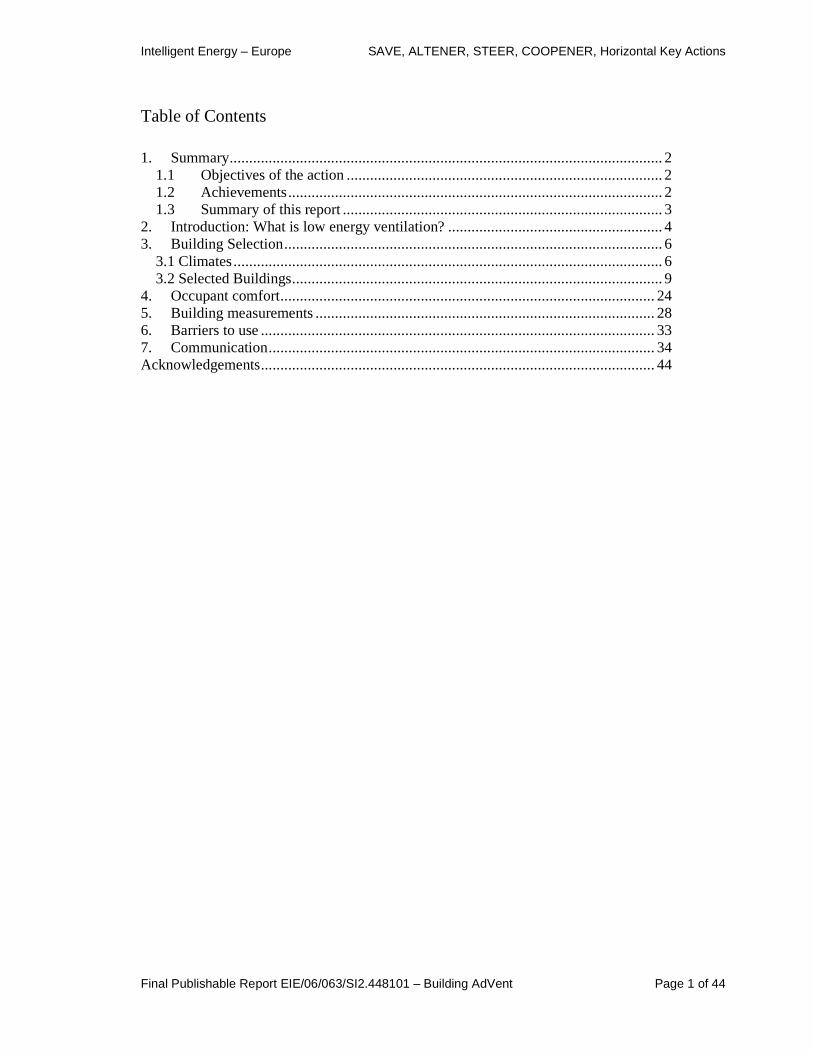
2. Introduction: W hat is low energy ventilation? This was the subject of the deliverable D5 of the project, classifying ventilation systems. This report in full is available on the project website. Our final approach to characterising ventilation systems is summarised below. It is quite complex, recognising that there are different fundamental approaches to delivering ventilation, different approaches to its supply and then a range of areas where energy can be saved, as compared to a ‘full’ air conditioning approach.
Table 1.
Characteristic Principle Characteristic Parameter
Single-Sided
Cross
Natural Ventilation
Stack
Natural and Mechanical in combination in the building Fan Assisted Natural Ventilation
Hybrid Ventilation
Mechanical Exhaust
Mechanical Supply
Ventilation Principle
Mechanical Ventilation
Balanced Supply and Exhaust
Mixing
Displacement Temperature and Ventilation Effectiveness
Air Distribution Principle
Ceiling supply
Transport Wind tower, Wind scoop, Low Pressure Ducts, Atrium Heat Recovery
Solar Preheating
Heating
Earth Coupling
Free Cooling Outdoor Air
Night Cooling
Earth Coupling
Chilled Beams and Ceilings
Fan-coils
Comfort cooling (temp control)
Cooling
Air conditioning (temp and humidity control) CAV
VAV (Demand Control)
Automatic and/or User Driven
IAQ and/or Thermal Comfort
Control
Air Tightness
Thermal mass, PCM
Water and Ice Storage
Energy Storage
Concrete Core Activation
Energy Efficiency Principle
Commissioning/ Maintenance

Intelligent Energy – Europe SAVE, ALTENER, STEER, COOPENER, Horizontal Key Actions
Final Publishable Report EIE/06/063/SI2.448101 – Building AdVent Page 5 of 44
There are many good sources of basic information on ventilation systems. Key amongst these are amongst our project partners:
• International Network for Information on Ventilation and Energy Performance INIVE, http://www.inive.org/ They in turn support the
• Air Infiltration and Ventilation Centre AIVC www.aivc.org
• The Federation of European HVAC Associations, REHVA http://www.rehva.eu/ There have also been a good number of EU sponsored projects on relevant subjects, including:
• VENT Dis.Course - IEE
• NATVENT – Joule
• STEVE – Thermie B
• TIP-Vent – Joule
• AIOLOS - Altener
• DUCT, AIRWAYS - SAVE
• URBVENT – Energy
• SOLVENT - Altener
• ResHyvent - Joule
• European Collaborative Action: (Urban Air, Indoor Environment and Human Exposure)

Intelligent Energy – Europe SAVE, ALTENER, STEER, COOPENER, Horizontal Key Actions
Final Publishable Report EIE/06/063/SI2.448101 – Building AdVent Page 6 of 44
3. Building Selection In the project process we set out to achieve the aims of communicating the benefits and risks of low energy ventilation systems mainly through case studies. The choice of these case studies was therefore particularly important in achieving the project goals. In choosing case studies there were a number of competing demands:
• Covering a range of climates.
• Covering different ventilation systems.
• Covering a range of different building types, but in a way that makes the findings comparable, e.g. not industrial buildings or dwellings, but offices / schools / other public buildings.
• Selecting successful buildings that perform well for energy, air quality and occupant satisfaction.
• Selecting attractive buildings that others would be interested in understanding
• Using buildings where some data were available already (the project funding did not allow for a full series of appraisals.
• Using buildings where gaps in data could be filled and publication would be allowed.
This list of parameters means that the final collection of projects must include some compromises, as not all of these conditions can be met in full. Nevertheless the final selection contains a good mix of buildings, systems and climates. 3.1 Climates A basic aim of the project was to demonstrate solutions relevant to the 3 main climate zones of Europe:
• High heating,
• High cooling, and
• Intermediate. However the reality of the climates of different countries is that there is more of a continuum of different conditions as we move from place to place. This can be seen in Figure and Figure below, which show the heating degree days and the cooling degree days for each of the locations we have eventually used in the project. There are fewer

Intelligent Energy – Europe SAVE, ALTENER, STEER, COOPENER, Horizontal Key Actions
Final Publishable Report EIE/06/063/SI2.448101 – Building AdVent Page 7 of 44
than 18 as some locations contained more than one building in the study (Athens, Porto and Helsinki). What is clear from the figures is that there is a continuous range of heating demands across the locations. Finland, not surprisingly has the highest heating degree days, but the other colder locations are only slightly more than the intermediate locations. Clearly the Southern Europe locations have much lower heating loads. For cooling degree days it is clear that the high cooling locations are well defined. However Linz, in Austria, has both a relatively high heating and cooling load, indicating that there could be a case for a fourth category of climate, being a ‘continental’ climate with higher cooling and heating loads.
Average annual heating degree days (15.5degC)
0
500
1000
1500
2000
2500
3000
3500
4000
Helsink
i
Turku
Linz
Aalbor
g
Copenh
agen
Bristo
l
Dublin
Coventry
Wallin
gford
Antwer
p
Liver
pool
Athen
sPor
to
Delphi
Lisbo
n
Cold
Moderate
Warm
Figure 1: total heating degree days

Intelligent Energy – Europe SAVE, ALTENER, STEER, COOPENER, Horizontal Key Actions
Final Publishable Report EIE/06/063/SI2.448101 – Building AdVent Page 8 of 44
Average annual cooling degree days (15.5degC)
0
200
400
600
800
1000
1200
1400
1600
1800
2000
Helsink
i
Turku
Linz
Aalbor
g
Copenh
agen
Bristo
l
Dublin
Coventry
Wallin
gford
Antwer
p
Liver
pool
Athen
sPor
to
Delphi
Lisbo
n
Cold
Moderate
Warm
Figure 2: total cooling degree days
Intelligent Energy – Europe SAVE, ALTENER, STEER, COOPENER, Horizontal Key Actions
Final Publishable Report EIE/06/063/SI2.448101 – Building AdVent Page 9 of 44
3.2 Selected Buildings Eighteen buildings were selected to be included in the study on the basis of the criteria set out previously. These are described briefly in this section.
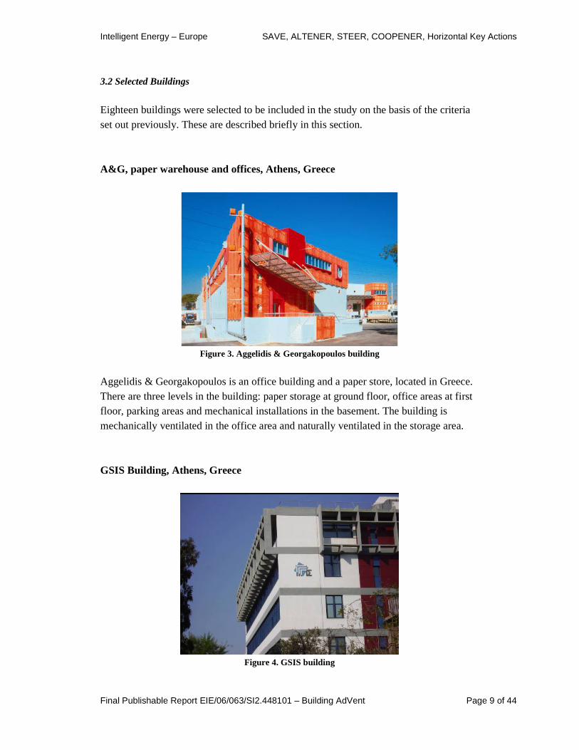
A&G, paper warehouse and offices, Athens, Greece
Figure 3. Aggelidis & Georgakopoulos building
Aggelidis & Georgakopoulos is an office building and a paper store, located in Greece. There are three levels in the building: paper storage at ground floor, office areas at first floor, parking areas and mechanical installations in the basement. The building is mechanically ventilated in the office area and naturally ventilated in the storage area.
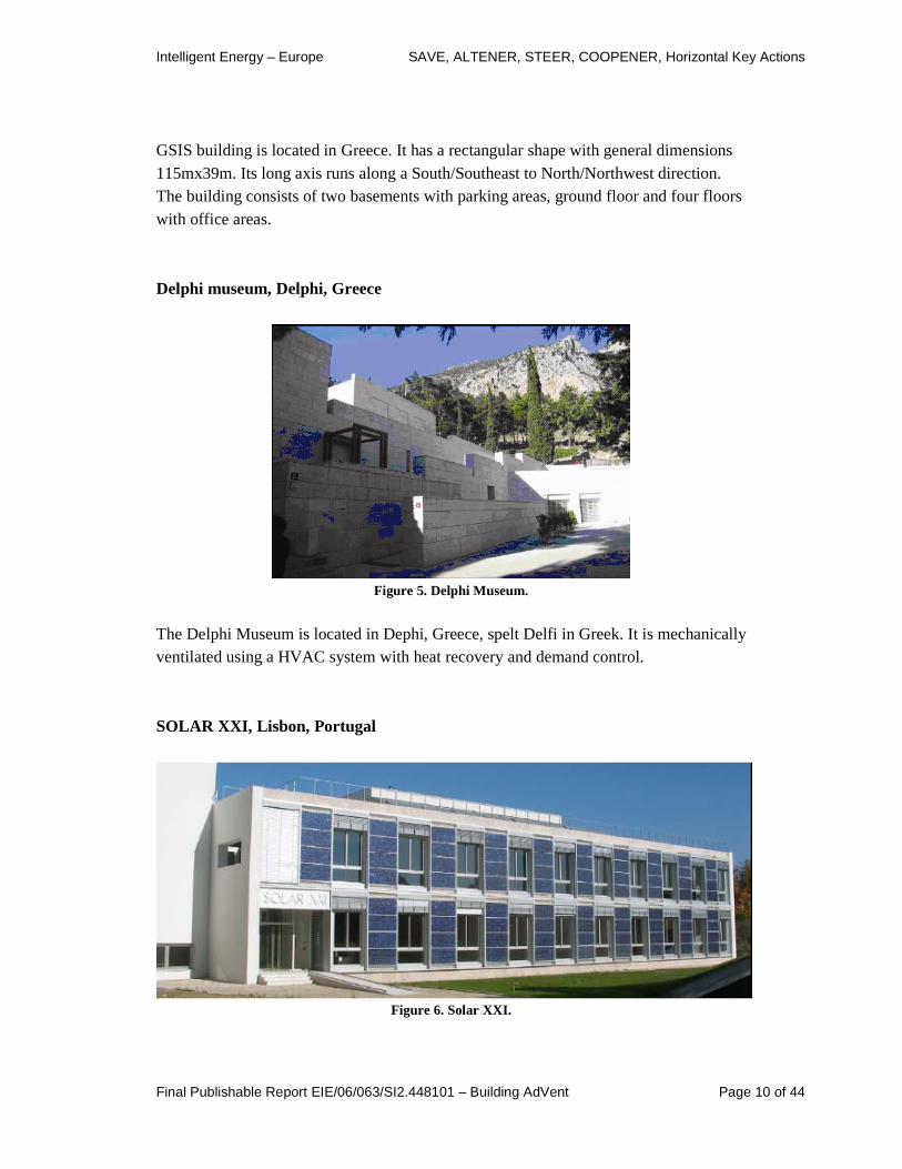
GSIS Building, Athens, Greece
Figure 4. GSIS building
Intelligent Energy – Europe SAVE, ALTENER, STEER, COOPENER, Horizontal Key Actions
Final Publishable Report EIE/06/063/SI2.448101 – Building AdVent Page 10 of 44
GSIS building is located in Greece. It has a rectangular shape with general dimensions 115mx39m. Its long axis runs along a South/Southeast to North/Northwest direction. The building consists of two basements with parking areas, ground floor and four floors with office areas.
Delphi museum, Delphi, Greece
Figure 5. Delphi Museum.
The Delphi Museum is located in Dephi, Greece, spelt Delfi in Greek. It is mechanically ventilated using a HVAC system with heat recovery and demand control.
SOLAR XXI, Lisbon, Portugal
Figure 6. Solar XXI.

Intelligent Energy – Europe SAVE, ALTENER, STEER, COOPENER, Horizontal Key Actions
Final Publishable Report EIE/06/063/SI2.448101 – Building AdVent Page 11 of 44
The Solar XXI building is located in Lisbon, Portugal. It is largely naturally ventilated, with mechanical supply of outside air through a set of buried pipes. An internal atrium allows communication with the main spaces via controllable air registers, and in this way promotes natural circulation of the air and air extraction at the top. Night ventilation can be used to promote summer cooling.
EPG - Edifício das Pós-graduações, Porto, Portugal
Figure 7. Edifício das Pós-graduações (EPG building).
This is a university building, with traditional mechanical systems. There is a heat recovery unit installed and also the free-cooling strategy can be used during the suitable weather conditions. Displacement ventilation is used in spaces with high internal loads.
Parque Expo 98, Lisbon, Portugal
Figure 8. Parque EXPO 98 HQ.
Intelligent Energy – Europe SAVE, ALTENER, STEER, COOPENER, Horizontal Key Actions
Final Publishable Report EIE/06/063/SI2.448101 – Building AdVent Page 12 of 44
The building has both natural and mechanical ventilation. When working with mechanical ventilation it has also the ability to work with 100% fresh air or with a percentage of recirculated air. Displacement ventilation is used for air distribution to the office rooms.
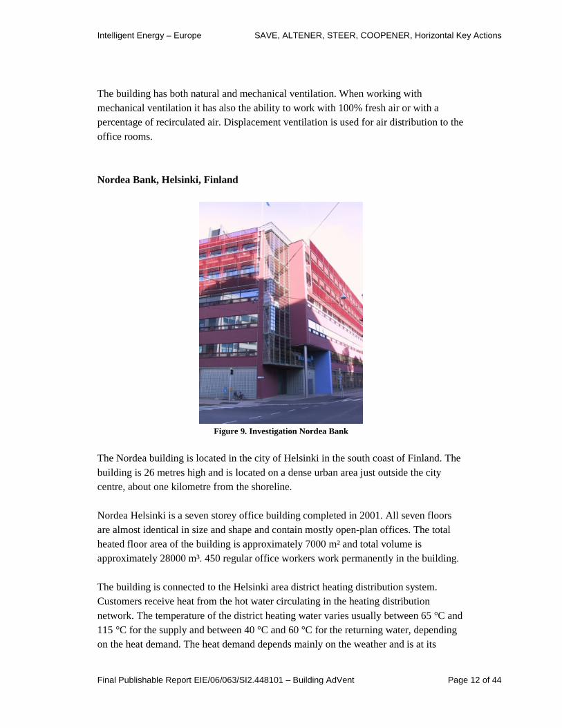
Nordea Bank, Helsinki, Finland
Figure 9. Investigation Nordea Bank
The Nordea building is located in the city of Helsinki in the south coast of Finland. The building is 26 metres high and is located on a dense urban area just outside the city centre, about one kilometre from the shoreline. Nordea Helsinki is a seven storey office building completed in 2001. All seven floors are almost identical in size and shape and contain mostly open-plan offices. The total heated floor area of the building is approximately 7000 m² and total volume is approximately 28000 m³. 450 regular office workers work permanently in the building. The building is connected to the Helsinki area district heating distribution system. Customers receive heat from the hot water circulating in the heating distribution network. The temperature of the district heating water varies usually between 65 °C and 115 °C for the supply and between 40 °C and 60 °C for the returning water, depending on the heat demand. The heat demand depends mainly on the weather and is at its

Intelligent Energy – Europe SAVE, ALTENER, STEER, COOPENER, Horizontal Key Actions
Final Publishable Report EIE/06/063/SI2.448101 – Building AdVent Page 13 of 44
lowest in the summer when heat is needed only for the domestic hot water. Heat extracted from the district heating network is used in the building for domestic hot water and space heating through central air handling units and hot water radiators.
Poikkilaakso School, Helsinki, Finland
Figure 10.The Poikkilaakso School.
This is an experimental school building, located in Finland, where some elements typical for hybrid systems are combined with mechanical ventilation. The ventilation system is fully mechanical low-pressure system, having a central air handling unit including filtering, heat recovery, etc. The building serves as an airflow route and there are no suspended ceilings or visible ducts inside. Air handling unit on the top of the roof is connected to large supply air duct on the roof, from which two vertical ducts lead to each classroom having displacement diffusers. Central spaces of the building are ventilated with transfer air from classrooms (no ducts). Extract is from the central hall.

Intelligent Energy – Europe SAVE, ALTENER, STEER, COOPENER, Horizontal Key Actions
Final Publishable Report EIE/06/063/SI2.448101 – Building AdVent Page 14 of 44
YIT Keskus, Turku, Finland
Figure 11. YIT Keskus.
This is a 5-storey rectangular building with heated basement. There is a large atrium space in the middle of the building. The offices are mainly open plan offices and also cellular offices. Ventilation is mainly CAV system with active chilled beams. Outdoor air is filtered and heated in an airhandling unit and supplied to rooms. Ventilation air is heated partly with heat recovered from extract air and district heating. Room is heated with hot water radiators. The water is heated with district heating, and flow controlled with thermostatic radiator valves. The air flow is constant to normal office rooms, but is CO2 and temperature controlled to meeting rooms. Supply air flow is selected based on ventilation requirements but is heated or cooled depending on the requirements of the room. Major part of cooling and heating is supplied by the water systems (beams and radiators respectively).

Intelligent Energy – Europe SAVE, ALTENER, STEER, COOPENER, Horizontal Key Actions
Final Publishable Report EIE/06/063/SI2.448101 – Building AdVent Page 15 of 44
Vejlandshuset (Energi), Copenhagen, Denmark
Figure 12. Københavns Energi, Vejlandshuset.
Vejlandshuset is a cube-shaped building with an atria-space in the middle. This is 5-storey, open space office building with approximately 400 employees. The building is naturally ventilated, except for the ground floor, which is mechanically ventilated. Natural ventilation is time, CO2 and temperature controlled. There is a possibility for the manual control of ventilation system in the building. The occupation density in the building varies from floor to floor and therefore the control over the IAQ and comfort conditions is carried out in each thermal zone separately.

Intelligent Energy – Europe SAVE, ALTENER, STEER, COOPENER, Horizontal Key Actions
Final Publishable Report EIE/06/063/SI2.448101 – Building AdVent Page 16 of 44
CHH– Christophorus Haus MIVA, Stadl Paura, Austria
Figure 13. CHH– Christophorus Haus MIVA.
This project describes the new built office building of the Catholic Church association “MIVA”. The association is active in development cooperation and mission work. One of their activities is to prepare all kinds of vehicles for developing countries. Therefore the building is of multifunctional use. Office building is combined with a logistics centre, there is also a warehouse for the aid shipments of BBM, a car-wash, premises for events and seminars, a world-shop, exhibition areas and a catering kitchen. The office building with 1,215 m² is a work place for 40 persons. The remaining building area is used for parking of the company’s cars (325 m²) and basement (550 m²). The building has a basement, a ground floor and two upper floors.
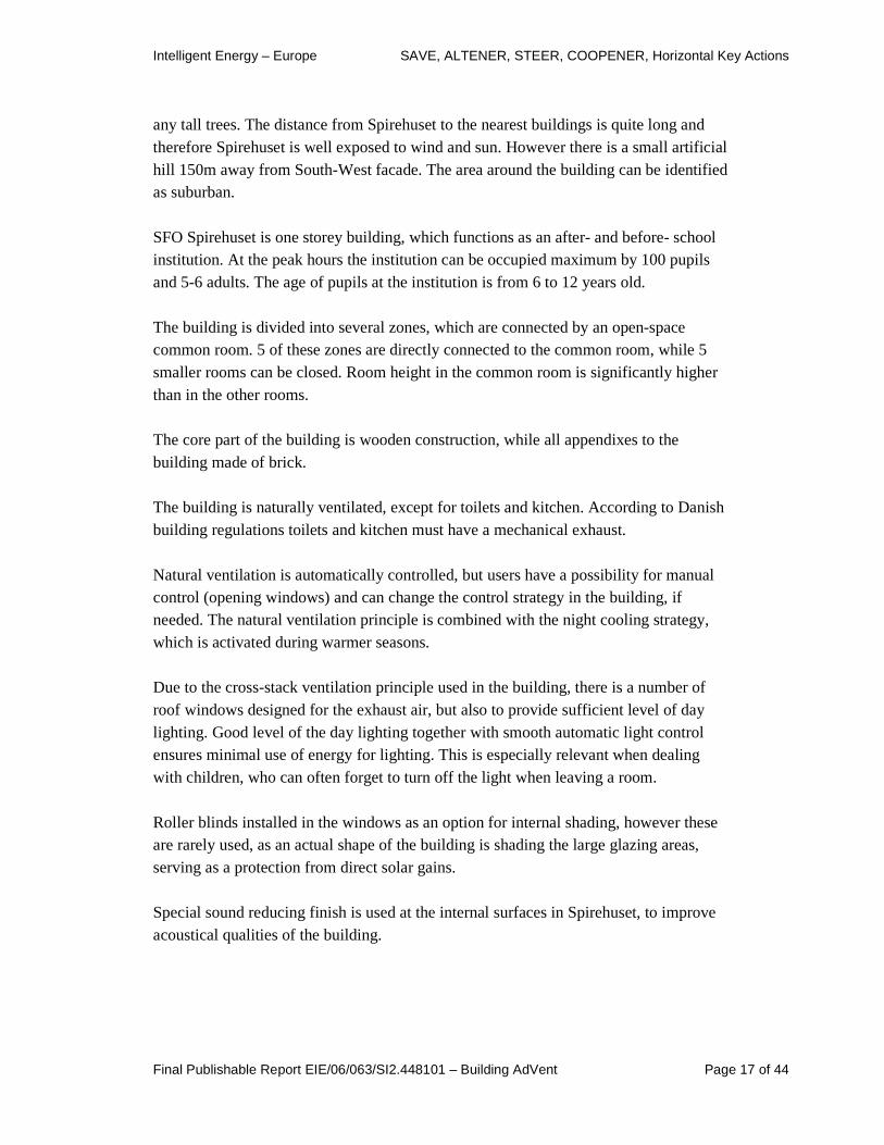
SFO Spirehuset, Hirtshals, Denmark
Figure 14. SFO Spirehuset
The building is located in a smaller town Hirtshals on the Northern coast of Denmark. In a neighbourhood of SFO Spirehuset, there are mainly one-storey buildings without
Intelligent Energy – Europe SAVE, ALTENER, STEER, COOPENER, Horizontal Key Actions
Final Publishable Report EIE/06/063/SI2.448101 – Building AdVent Page 17 of 44
any tall trees. The distance from Spirehuset to the nearest buildings is quite long and therefore Spirehuset is well exposed to wind and sun. However there is a small artificial hill 150m away from South-West facade. The area around the building can be identified as suburban. SFO Spirehuset is one storey building, which functions as an after- and before- school institution. At the peak hours the institution can be occupied maximum by 100 pupils and 5-6 adults. The age of pupils at the institution is from 6 to 12 years old. The building is divided into several zones, which are connected by an open-space common room. 5 of these zones are directly connected to the common room, while 5 smaller rooms can be closed. Room height in the common room is significantly higher than in the other rooms. The core part of the building is wooden construction, while all appendixes to the building made of brick. The building is naturally ventilated, except for toilets and kitchen. According to Danish building regulations toilets and kitchen must have a mechanical exhaust. Natural ventilation is automatically controlled, but users have a possibility for manual control (opening windows) and can change the control strategy in the building, if needed. The natural ventilation principle is combined with the night cooling strategy, which is activated during warmer seasons. Due to the cross-stack ventilation principle used in the building, there is a number of roof windows designed for the exhaust air, but also to provide sufficient level of day lighting. Good level of the day lighting together with smooth automatic light control ensures minimal use of energy for lighting. This is especially relevant when dealing with children, who can often forget to turn off the light when leaving a room. Roller blinds installed in the windows as an option for internal shading, however these are rarely used, as an actual shape of the building is shading the large glazing areas, serving as a protection from direct solar gains. Special sound reducing finish is used at the internal surfaces in Spirehuset, to improve acoustical qualities of the building.

Intelligent Energy – Europe SAVE, ALTENER, STEER, COOPENER, Horizontal Key Actions
Final Publishable Report EIE/06/063/SI2.448101 – Building AdVent Page 18 of 44
City Academy, Bristol, UK
Figure 15. The Bristol City Academy
The school is arranged in five villages, each pupil is a member of one village throughout their secondary education. The orientation of classes are mainly NE/SW, however the geometry means that solar exposure occurs in most directions. The school has a sports specialism and has a separate sports centre onsite. A mixed /ventilation principle is applied in the building with different systems serving different areas. Ventilation through windows and small supply and extract fans serve the ground floor classrooms. Natural air supply is designed through windows in the first floor classrooms with the air extract through motorized openings at high level. Some classrooms have a natural air supply via a buried concrete pipe with a mechanical extract on the ground floor and natural extract on the first. For special rooms cooling is provided from split air conditioning systems.

Intelligent Energy – Europe SAVE, ALTENER, STEER, COOPENER, Horizontal Key Actions
Final Publishable Report EIE/06/063/SI2.448101 – Building AdVent Page 19 of 44
St Francis of Assisi Academy, Liverpool, UK
Figure 16. Liverpool (Kensington) Academy.
The school has a specialism in the environment and it was the intention of the design team to demonstrate this through design. The school is orientated with main facades facing North/South. The school is organized over 5 levels, from the single level, ground floor Year 7 & 8 classrooms to the three storey full height atrium. The halls in the basement of the school are mechanically ventilated, incorporating heat recovery and demand controlled ventilation based on carbon dioxide levels in the space. The ICT space, music practice rooms and server rooms have mechanical supply and extract with room Fan Coil Units. Cooling is supplied via a Variable Refrigerant Flow, heat-recovery air-source heat-pump. This allows heat to be effectively moved between zones and suits a simultaneous heating and cooling demand. Science and technology rooms on the ground and first floor teaching blocks are mechanically ventilated to reduce noise ingress, however the second and third floor classes are naturally ventilated due to a dispensation to save money. The ETFE atria is naturally ventilated on the South side and extracts at high-level on the North facade, through an external plant room.
Intelligent Energy – Europe SAVE, ALTENER, STEER, COOPENER, Horizontal Key Actions
Final Publishable Report EIE/06/063/SI2.448101 – Building AdVent Page 20 of 44
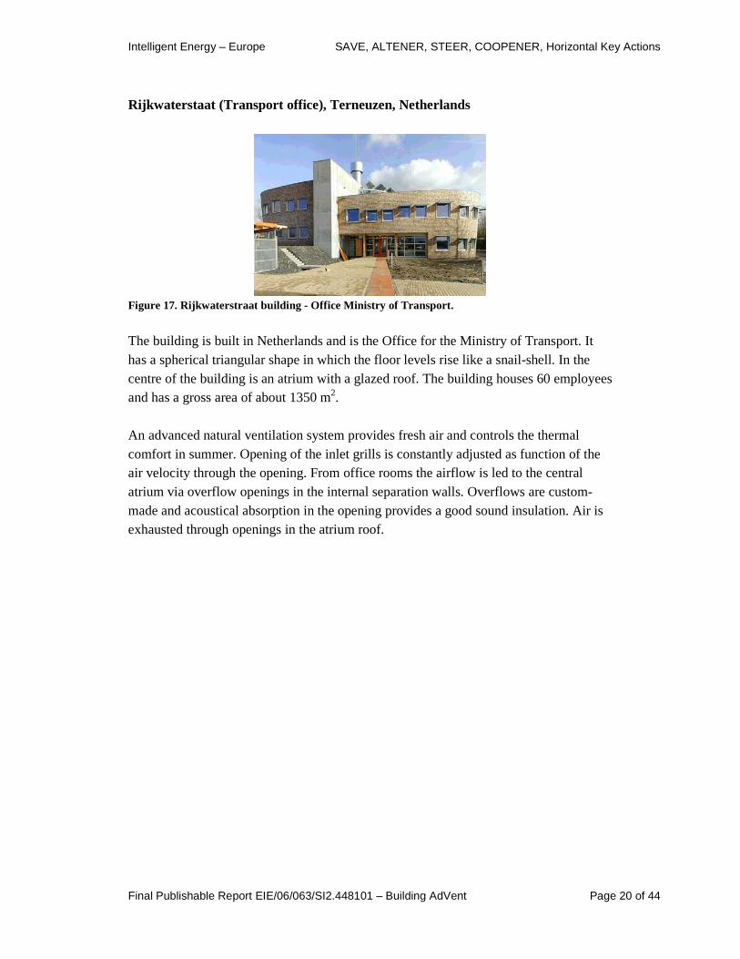
Rijkwaterstaat (Transport office), Terneuzen, Netherlands
Figure 17. Rijkwaterstraat building - Office Minist ry of Transport.
The building is built in Netherlands and is the Office for the Ministry of Transport. It has a spherical triangular shape in which the floor levels rise like a snail-shell. In the centre of the building is an atrium with a glazed roof. The building houses 60 employees and has a gross area of about 1350 m2. An advanced natural ventilation system provides fresh air and controls the thermal comfort in summer. Opening of the inlet grills is constantly adjusted as function of the air velocity through the opening. From office rooms the airflow is led to the central atrium via overflow openings in the internal separation walls. Overflows are custom-made and acoustical absorption in the opening provides a good sound insulation. Air is exhausted through openings in the atrium roof.

Intelligent Energy – Europe SAVE, ALTENER, STEER, COOPENER, Horizontal Key Actions
Final Publishable Report EIE/06/063/SI2.448101 – Building AdVent Page 21 of 44
Aras Chill Dara building, Naas, Ireland
Figure 18. Aras Chill Dara.
These offices are the home of Kildare County Council and are located in Ireland. The building is zoned into three areas – natural ventilation, mechanical ventilation, and comfort cooling/air-conditioning. However the bulk of the occupied space is naturally ventilated. The total building area is 12,500 m2. The building is arranged in two wings, with sections of 3 and 4 storey height, connected by a central ramp. Facades are orientated to the East/West, with rain screen cladding applied to reduce solar gains.
Frederick Lanchester Library, Coventry, UK
Figure 19. Frederick Lanchester Library
Intelligent Energy – Europe SAVE, ALTENER, STEER, COOPENER, Horizontal Key Actions
Final Publishable Report EIE/06/063/SI2.448101 – Building AdVent Page 22 of 44
The Frederick Lanchester Library is unusual in that it is a deep-plan building occupying a 50m by 50m footprint and is ventilated naturally with no artificial cooling, except for a separate basement storage area which is air-conditioned. In order to provide natural ventilation a tapering central lightwell provides extract ventilation, supplemented by 20 perimeter stacks with a 1.8m by 1.8m cross section. The stacks terminate 6m above roof levels with fittings to prevent reverse flow due to wind pressure. Air entry is via a plenum under the ground floor to the base of four 6m by 6m square corner lightwells. Under the influence of stack effect air is drawn via the four corner lightwells into each floor and extracted via the central lightwell and the smaller stacks. In winter the incoming air is warmed by pre-heating coils at the base of the supply lightwells and by trench heating at the point that the air from the lightwells enters each floor. Cooling is provided passively by thermally heavy-weight ceilings. By its nature the building has a large number of transient occupants. At the design stage 2,500 entries per day were anticipated. In practice, this has increased to 5,000. In addition a number of staff work permanently in the building. The building is open for use for approximately 4,000 hours per year.
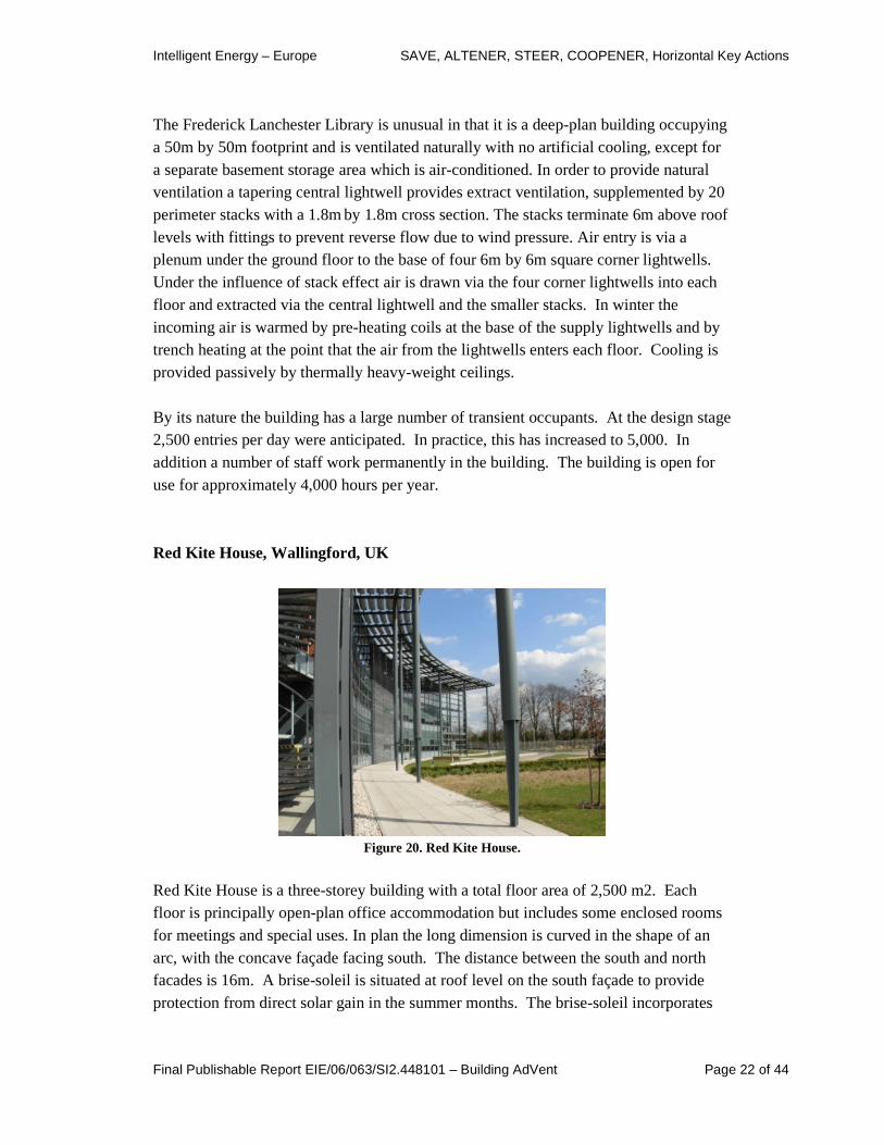
Red Kite House, Wallingford, UK
Figure 20. Red Kite House.
Red Kite House is a three-storey building with a total floor area of 2,500 m2. Each floor is principally open-plan office accommodation but includes some enclosed rooms for meetings and special uses. In plan the long dimension is curved in the shape of an arc, with the concave façade facing south. The distance between the south and north facades is 16m. A brise-soleil is situated at roof level on the south façade to provide protection from direct solar gain in the summer months. The brise-soleil incorporates

Intelligent Energy – Europe SAVE, ALTENER, STEER, COOPENER, Horizontal Key Actions
Final Publishable Report EIE/06/063/SI2.448101 – Building AdVent Page 23 of 44
photovoltaic cells which reduce the building’s electricity demand on conventional grid supply. Roof-mounted thermal solar collectors provide hot water for washrooms. The building is naturally ventilated by automatically controlled high-level windows on each floor of the main facades. Larger manually operated windows are also available. The ceiling of each storey is exposed concrete. This thermal mass is used in conjunction with night-time ventilation to reduce peak internal temperatures in summer.
Intelligent Energy – Europe SAVE, ALTENER, STEER, COOPENER, Horizontal Key Actions
Final Publishable Report EIE/06/063/SI2.448101 – Building AdVent Page 24 of 44
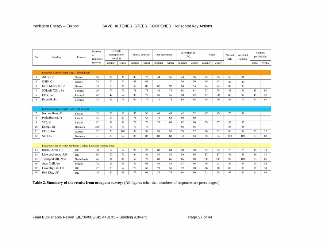
4. Occupant comfort Occupant comfort is the subject of deliverables D7 and D8, with the work led by AAU from Denmark. The purpose of the work was to understand the response of building users to the buildings they occupy, and thereby to understand any problems that might be expected to occur with the low energy ventilation systems in practice. The following section is an extract from report D8. Table 3-1 and figure 3-1 present a complete overview of user evaluation in each building. In Figure , one can observe distribution of votes of satisfied occupants by each building. It is seen that there are a number of buildings with relatively low overall levels of satisfaction. However, buildings with low satisfaction votes were investigated in detail, together with reasons for dissatisfaction pointed out by the occupants. These are discussed in the report D7. As an example the City Academy in Bristol shows up with very low scores for thermal comfort. This reflects the fact that questionnaire data were carried out before subsequent work to manage the heating and ventilation systems better, and would be expected to be higher if repeated. One of the key challenges set up by using the questionnaire approach is that the view of people on buildings is very complex, and is known to be affected by their motivation towards the organisation that runs the building. This means that it requires care to compare different buildings; it is more reliable to look at the results as an indication of where there are issues in a given building. In this way the occupants act as a valuable diagnostic tool, enabling building problems to be identified. No insurmountable problems were detected from the questionnaire process; where occupants were dissatisfied it was normally with a building element that was not working correctly.

Intelligent Energy – Europe SAVE, ALTENER, STEER, COOPENER, Horizontal Key Actions
Final Publishable Report EIE/06/063/SI2.448101 – Building AdVent Page 25 of 44
0
10
20
30
40
50
60
70
80
90
100
summer winter summer winter summer winter summer winter summer winter temp. ventil.
Overall perception of
comfort
Thermal comfort Air movement Perception of IAQ Noise Natural
light
Artificial
lighting
Control possibilities
Per
cent
age
satis
fied
A&G, Gr GSIS, Gr Delfi Museum, Gr SOLAR XXI , Po EPG, PO Expo 98, Po
Nordea Bank, Fi Poikkilaakso, Fi YIT, Fi Energi, De CHH, Aus SFO, De
Bristol Acad, UK Liverpool Acad, UK Transport Off, Ned Aras Chill, Ire Coventry Lib, UK Red Kite, UK
Figure 21. Summary over the results from occupant surveys by building.
Intelligent Energy – Europe SAVE, ALTENER, STEER, COOPENER, Horizontal Key Actions
Final Publishable Report EIE/06/063/SI2.448101 – Building AdVent Page 26 of 44
0
10
20
30
40
50
60
70
80
90
100
A&G, G
r
GSI
S, G
r
Del
fi M
useu
m, G
r
SOLA
R XXI
, Po
EPG
, PO
Expo 9
8, P
o
Nord
ea B
ank,
Fi
Poikki
laaks
o, Fi
YIT, F
i
Energ
i, D
e
CHH
, Aus
SFO, D
e
Bristo
l Aca
d, UK
Live
rpool A
cad, U
K
Tran
sport
Off, N
ed
Aras
Chill, I
re
Coventr
y Lib, U
K
Red Ki
te, U
K
Per
cent
age
satis
fied
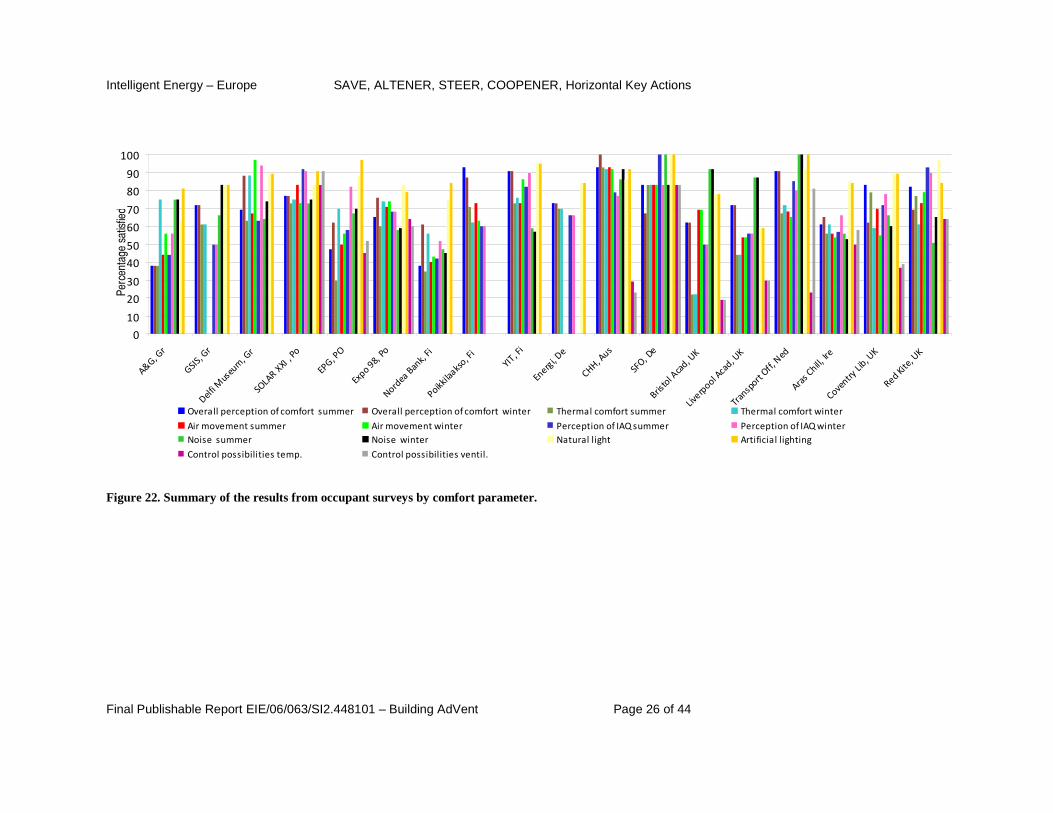
Overall perception of comfort summer Overall perception of comfort winter Thermal comfort summer Thermal comfort winter
Air movement summer Air movement winter Perception of IAQ summer Perception of IAQ winter
Noise summer Noise winter Natural light Artificial lighting
Control possibilities temp. Control possibilities ventil. Figure 22. Summary of the results from occupant surveys by comfort parameter.
Intelligent Energy – Europe SAVE, ALTENER, STEER, COOPENER, Horizontal Key Actions
Final Publishable Report EIE/06/063/SI2.448101 – Building AdVent Page 27 of 44
Overall
perception of comfort
Thermal comfort Air movement Perception of
IAQ Noise
Control possibilities No Building Country
Number of responses received summer winter summer winter summer winter summer winter summer winter
Natural light
Artificial lighting
temp. ventil.
European Climates with High Cooling Load
1 A&G, Gr Greece 16 38 38 38 75 44 56 44 56 75 75 63 81
2 GSIS, Gr Greece 74 72 72 61 61 50 50 66 83 83 83
3 Delfi Museum, Gr Greece 33 69 88 63 88 67 97 63 94 64 74 89 89
4 SOLAR XXI , Po Portugal 19 77 77 73 75 83 73 92 91 73 75 83 91 83 91
5 EPG, Po Portugal 42 47 62 30 70 50 56 58 82 67 70 88 97 45 52
6 Expo 98, Po Portugal 75 65 76 60 74 71 74 68 68 58 59 83 79 64 60
European Climates with High Heating Load
7 Nordea Bank, Fi Finland 35 38 61 35 56 40 43 42 52 47 45 75 84
8 Poikkilaakso, Fi Finland 16 93 87 71 62 73 63 60 60
9 YIT, Fi Finland 22 91 91 73 76 73 86 82 90 59 57 95 95
10 Energi, De Denmark 366 73 73 70 70 66 66 84 84
11 CHH, Aus Austria 17 93 100 93 92 93 92 79 77 86 92 86 92 29 23
12 SFO, De Denmark 6 83 67 83 83 83 83 100 83 100 83 100 100 83 83
European Climates with Moderate Cooling Load and Heating Load
13 Bristol Acad, UK UK 38 62 62 22 22 69 69 50 50 92 92 78 78 19 19
14 Liverpool Acad, UK UK 39 72 72 44 44 54 54 56 56 87 87 59 59 30 30
15 Transport Off, Ned Netherlands 26 91 91 67 72 68 65 85 80 100 100 92 100 23 81
16 Aras Chill, Ire Ireland 152 61 65 56 61 56 54 57 66 56 53 85 84 50 58
17 Coventry Lib, UK UK 47 83 62 79 59 70 55 72 78 66 60 89 89 37 39
18 Red Kite, UK UK 143 82 69 77 61 73 79 93 90 51 65 97 84 64 64
Table 2. Summary of the results from occupant surveys (All figures other than numbers of responses are percentages.)

Intelligent Energy – Europe SAVE, ALTENER, STEER, COOPENER, Horizontal Key Actions
Final Publishable Report EIE/06/063/SI2.448101 – Building AdVent Page 28 of 44
5. Building measurements In this section the approach to some of the measurement processes is presented, as a support to others who may be attempting a similar project.
UK tests In the UK measurements were carried out in two academies. For both tests, a tracer decay test was conducted (using CO2 as the tracer gas). The tests are intended to be representative of the building operating in the heating season with all of the windows closed. The results are therefore indicative of the ‘worst-case scenario’ of ventilation performance. Time permitting; an open window test was conducted to assess the maximum ventilation rate.
Ventilation Testing The purpose of the ventilation tests were to inform assumptions regarding rates of fresh air ingress for design purposes. Two methods were used within the classrooms. In most rooms the researcher was interested in the ventilation rates during normal occupancy, and therefore used CO2 monitoring equipment (TSI, 8551 accuracy of ± 3%) was used. The ventilation rate was inferred using a method described in Coley (2001) and Pegg (2005). The method is described as the tracer decay method and infers the ventilation using the following equation:
tV
Q
exinext eQ
GCC
Q
GCC
−
−−++=
(Where, Ct = concentration of CO2 at time t (ppm) Cex = concentration of external CO2 (ppm) G = amount of CO2 generated in the time period t (cm3/s) Q = internal-external exchange rate (m3/s) Cin = initial concentration of the tracer gas (ppm) V = room volume (m3) t = time (s)) The current unknowns are the external levels of CO2 in the atmosphere, which were fairly steady at approximately 380ppm, the room volume, which is measured from drawings and the amount of CO2 generated (G). This led to a figure of approximately 15 litres per hour for children and 20.6 for adults.

Intelligent Energy – Europe SAVE, ALTENER, STEER, COOPENER, Horizontal Key Actions
Final Publishable Report EIE/06/063/SI2.448101 – Building AdVent Page 29 of 44
The equation was solved using a numerical approximation method using Matlab. Sample periods were constrained to moving 10 minute periods and report the average ventilation rate for that period was reported.
Academy of St Francis of Assisi, Liverpool A second floor NV classroom was investigated to assess the infiltration and ventilation (windows open) rate. The corresponding ventilation rates calculated were 0.21 ACH and 3.51 ACH respectively. Decay rate results are shown graphically below.
Figure 23.
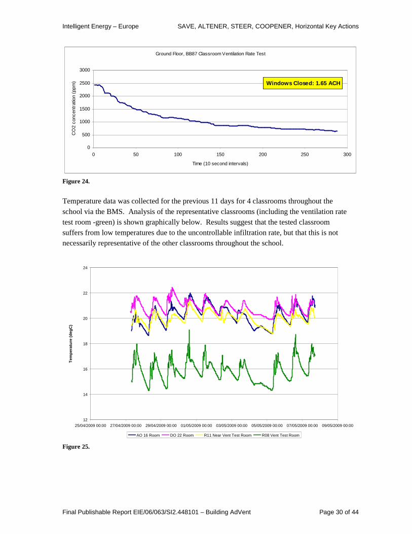
City Academy, Bristol A relatively high natural infiltration rate was measured in the representative Bristol Academy classroom. Testing was conducted during term-time and a ground floor BB87 (damped mechanical ventilation) was made available. The ventilation system was switched off and left off for a reasonable period before testing commenced. The measured infiltration rate was 1.65 ACH.
Window Closed Inf iltration Rate
0
500
1000
1500
2000
2500
3000
0 100 200 300 400 500 600
Time (10 second intervals)
CO
2 C
ocen
trat
ion
(ppm
)
Windows Closed: 0.21 ACH
Window Open Ventilation Rate
0
500
1000
1500
2000
2500
3000
0 20 40 60 80 100 120 140 160 180
Time (10 second intervals)
CO
2 C
once
ntra
tion
(ppm
)
Windows Open: 3.51 ACH
Intelligent Energy – Europe SAVE, ALTENER, STEER, COOPENER, Horizontal Key Actions
Final Publishable Report EIE/06/063/SI2.448101 – Building AdVent Page 30 of 44
Ground Floor, BB87 Classroom Ventilation Rate Test
0
500
1000
1500
2000
2500
3000
0 50 100 150 200 250 300
Time (10 second intervals)
CO
2 co
ncen
trat
ion
(ppm
) Windows Closed: 1.65 ACH
Figure 24.
Temperature data was collected for the previous 11 days for 4 classrooms throughout the school via the BMS. Analysis of the representative classrooms (including the ventilation rate test room -green) is shown graphically below. Results suggest that the tested classroom suffers from low temperatures due to the uncontrollable infiltration rate, but that this is not necessarily representative of the other classrooms throughout the school.
12
14
16
18
20
22
24
25/04/2009 00:00 27/04/2009 00:00 29/04/2009 00:00 01/05/2009 00:00 03/05/2009 00:00 05/05/2009 00:00 07/05/2009 00:00 09/05/2009 00:00
Tem
per
atu
re (
deg
C)
AO 16 Room DO 22 Room R11 Near Vent Test Room R08 Vent Test Room
Figure 25.
Intelligent Energy – Europe SAVE, ALTENER, STEER, COOPENER, Horizontal Key Actions
Final Publishable Report EIE/06/063/SI2.448101 – Building AdVent Page 31 of 44
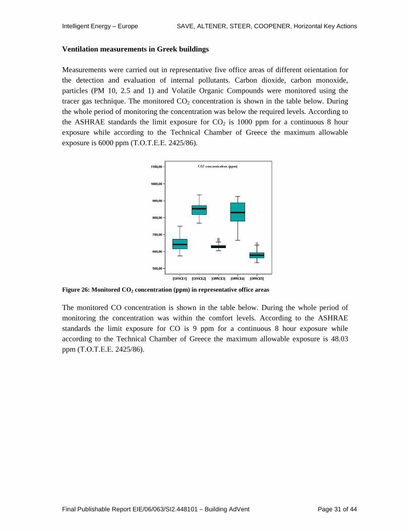
Ventilation measurements in Greek buildings Measurements were carried out in representative five office areas of different orientation for the detection and evaluation of internal pollutants. Carbon dioxide, carbon monoxide, particles (PM 10, 2.5 and 1) and Volatile Organic Compounds were monitored using the tracer gas technique. The monitored CO2 concentration is shown in the table below. During the whole period of monitoring the concentration was below the required levels. According to the ASHRAE standards the limit exposure for CO2 is 1000 ppm for a continuous 8 hour exposure while according to the Technical Chamber of Greece the maximum allowable exposure is 6000 ppm (Τ.Ο.Τ.Ε.Ε. 2425/86).
Figure 26: Monitored CO2 concentration (ppm) in representative office areas
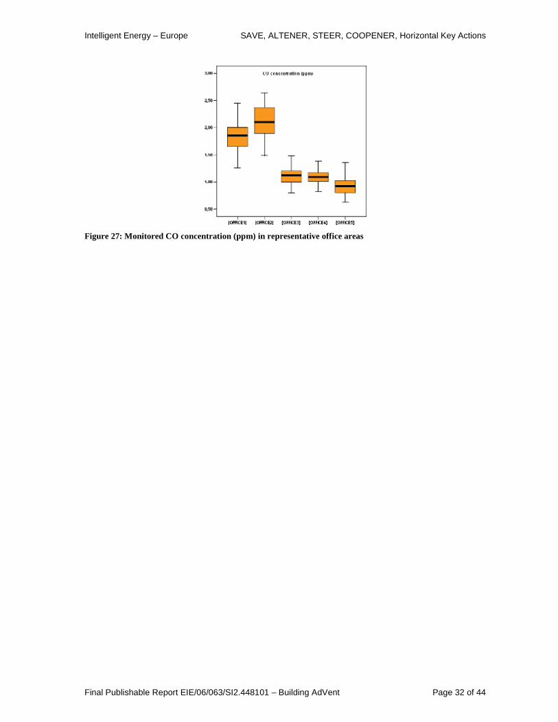
The monitored CO concentration is shown in the table below. During the whole period of monitoring the concentration was within the comfort levels. According to the ASHRAE standards the limit exposure for CO is 9 ppm for a continuous 8 hour exposure while according to the Technical Chamber of Greece the maximum allowable exposure is 48.03 ppm (Τ.Ο.Τ.Ε.Ε. 2425/86).
Intelligent Energy – Europe SAVE, ALTENER, STEER, COOPENER, Horizontal Key Actions
Final Publishable Report EIE/06/063/SI2.448101 – Building AdVent Page 32 of 44
Figure 27: Monitored CO concentration (ppm) in representative office areas
Intelligent Energy – Europe SAVE, ALTENER, STEER, COOPENER, Horizontal Key Actions
Final Publishable Report EIE/06/063/SI2.448101 – Building AdVent Page 33 of 44
6. Barriers to use Within the project report D9, the issues of barriers to the take up of innovative ventilation systems are addressed. This is addressed in two parts. The first shorter part is a discussion of the whole range barriers to these systems. It is based on the knowledge of the project team, and a workshop held in Gent, Belgium in 2008. These issues are summarised as follows
• Difficulty in ensuring satisfactory conditions.
• Suitable location.
• Increased complexity for the designer.
• Increased complexity for the product manufacturer.
• Warranty period.
• Low energy prices during the last decades.
• Different priorities for building investor and building users.
• Payment schemes for designers and consultants.
• Lack of performance oriented standards and regulations.
• Limited attention for indoor environment and energy efficiency in project specific requirements.
• Lack of clear and consistent messages towards decision makers.
• Lack of control and/or need for more refined control (including commissioning.)
• Difficulties for detecting lack of quality. For many of these issues this project can do little more than identify them. However the first two items are the main topic addressed in the D9 report, through a set of modelling studies of buildings. This set out to help designers understand the types of issues that will arise for designing ventilation systems. This is in terms of where the building is in climate terms, where it is in city location and what type of building it is and how this affects the outcome. There can be no general solution to this problem, as each building will need to be analysed individually, but these studies given indications of the direction to be taken.

Intelligent Energy – Europe SAVE, ALTENER, STEER, COOPENER, Horizontal Key Actions
Final Publishable Report EIE/06/063/SI2.448101 – Building AdVent Page 34 of 44
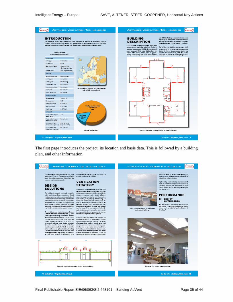
7. Communication The most important outputs from the project are the building brochures. An example of the layout is set out here, in order to explain the structure being used. The basic principle was to provide a set of case studies that enabled designers to take ideas and apply them successfully. Therefore sufficient information needs to be provided to explain the context in which the ventilation technologies have been applied. This will ensure that the solution’s strengths and weaknesses can be fully understood. The front page shows the building and its name
Intelligent Energy – Europe SAVE, ALTENER, STEER, COOPENER, Horizontal Key Actions
Final Publishable Report EIE/06/063/SI2.448101 – Building AdVent Page 35 of 44
The first page introduces the project, its location and basis data. This is followed by a building plan, and other information.
Intelligent Energy – Europe SAVE, ALTENER, STEER, COOPENER, Horizontal Key Actions
Final Publishable Report EIE/06/063/SI2.448101 – Building AdVent Page 36 of 44
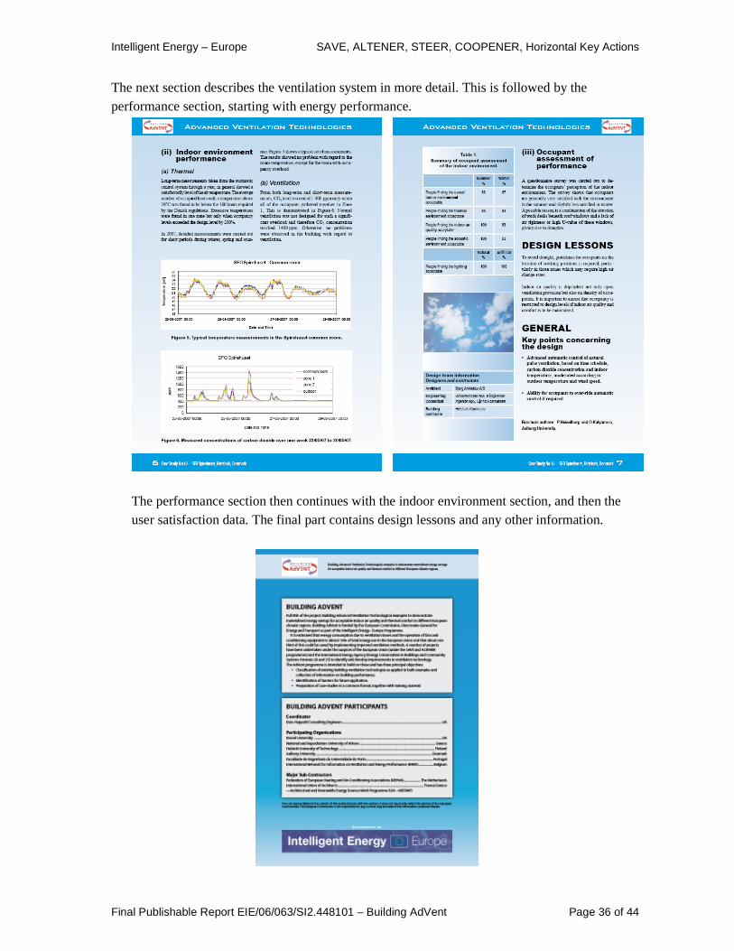
The next section describes the ventilation system in more detail. This is followed by the performance section, starting with energy performance.
The performance section then continues with the indoor environment section, and then the user satisfaction data. The final part contains design lessons and any other information.
Intelligent Energy – Europe SAVE, ALTENER, STEER, COOPENER, Horizontal Key Actions
Final Publishable Report EIE/06/063/SI2.448101 – Building AdVent Page 37 of 44
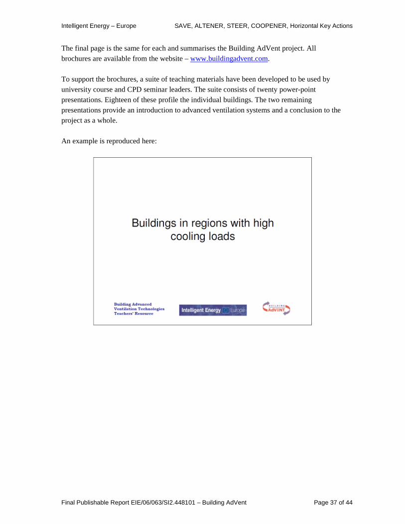
The final page is the same for each and summarises the Building AdVent project. All brochures are available from the website – www.buildingadvent.com. To support the brochures, a suite of teaching materials have been developed to be used by university course and CPD seminar leaders. The suite consists of twenty power-point presentations. Eighteen of these profile the individual buildings. The two remaining presentations provide an introduction to advanced ventilation systems and a conclusion to the project as a whole. An example is reproduced here:

Intelligent Energy – Europe SAVE, ALTENER, STEER, COOPENER, Horizontal Key Actions
Final Publishable Report EIE/06/063/SI2.448101 – Building AdVent Page 38 of 44

Intelligent Energy – Europe SAVE, ALTENER, STEER, COOPENER, Horizontal Key Actions
Final Publishable Report EIE/06/063/SI2.448101 – Building AdVent Page 39 of 44

Intelligent Energy – Europe SAVE, ALTENER, STEER, COOPENER, Horizontal Key Actions
Final Publishable Report EIE/06/063/SI2.448101 – Building AdVent Page 40 of 44

Intelligent Energy – Europe SAVE, ALTENER, STEER, COOPENER, Horizontal Key Actions
Final Publishable Report EIE/06/063/SI2.448101 – Building AdVent Page 41 of 44

Intelligent Energy – Europe SAVE, ALTENER, STEER, COOPENER, Horizontal Key Actions
Final Publishable Report EIE/06/063/SI2.448101 – Building AdVent Page 42 of 44
All slides are available in Danish, Finnish, Greek and Portuguese.
Intelligent Energy – Europe SAVE, ALTENER, STEER, COOPENER, Horizontal Key Actions
Final Publishable Report EIE/06/063/SI2.448101 – Building AdVent Page 43 of 44
Other dissemination Communication was the fundamental element in this project, and so the dissemination strategy was central to its success. We targeted a variety of channels for communication:
• Published articles.
• Conference presentations.
• Project newsletters distributed through partners’ networks.
• Own website www.buildingadvent.com.
• Websites of other linked organisations.
• Teaching within partner universities. The reader is encouraged to make use of the wealth of resources available on the project website.

Intelligent Energy – Europe SAVE, ALTENER, STEER, COOPENER, Horizontal Key Actions
Final Publishable Report EIE/06/063/SI2.448101 – Building AdVent Page 44 of 44
Acknowledgements The Building AdVent partners would like to thank Intelligent Energy Europe for generously funding this project and the owners, occupants and operators of the reviewed buildings for their invaluable co-operation.