Intelligent Compact Drives IclA N065 - pneumatykanet.pl · The drive systems with angular worm...
28
Intelligent Compact Drives IclA N065 Catalogue January 2009
Transcript of Intelligent Compact Drives IclA N065 - pneumatykanet.pl · The drive systems with angular worm...
Intelligent Compact Drives IclA N065
Catalogue
January 2009

Schneider Electric Motion Catalogue IclA N065 1
IclA N065 Table of contents
Product description . . . . . . . . . . . . . . . . . . . . . . . . . . . 2
Functions . . . . . . . . . . . . . . . . . . . . . . . . . . . . . . . . . . 7
IclA N065 without gearing
Technical data . . . . . . . . . . . . . . . . . . . . . . . . . . . . . . . . . . . . . 9
Dimensional drawings . . . . . . . . . . . . . . . . . . . . . . . . . . . . . . 11
IclA N065 with spur wheel gearing
Technical data . . . . . . . . . . . . . . . . . . . . . . . . . . . . . . . . . . . . 12
Dimensional drawings . . . . . . . . . . . . . . . . . . . . . . . . . . . . . . 14
IclA N065 with angular worm gearing
Technical data . . . . . . . . . . . . . . . . . . . . . . . . . . . . . . . . . . . . 15
Dimensional drawings . . . . . . . . . . . . . . . . . . . . . . . . . . . . . . 17
Type code . . . . . . . . . . . . . . . . . . . . . . . . . . . . . . . . . 18
Accessories
Software and documentation . . . . . . . . . . . . . . . . . . . . . . . . . 19
GBX planetary gearboxes . . . . . . . . . . . . . . . . . . . . . . . . . . . 20
Appendix
Conversion tables . . . . . . . . . . . . . . . . . . . . . . . . . . . . . . . . . 23

IclA N065Product description
The IclA N065 intelligent compact drives are servo drives based on an electronically commutated three-phase synchronous motor, referred to as an EC motor, and a block-commutated positioning controller. Power and control electronics with fieldbus terminal, motor, position sensor and gearing are integrated in the compact unit.
The compact drives are designed primarily for automatic positioning of format axes during setup of production machines or for point-to-point positioning of handling sy-stems.
• Compact construction• Low wiring requirements• Integrated positioning and speed control functions as specified by CiA profiles
DS301 and DS402• Fieldbus interface• High power density• High availability• 4 gearing models• Gearing options: spur wheel gearing, angular worm gearing, planetary
gearboxes (accessory)
The magnetisation of the motors guarantees high detent torque, making it unneces-sary to use a holding brake in many applications. The motors have an internal reso-lution of 12 increments per revolution. Spur wheel gearing and angular worm gearing are available. The intelligent compact drives can also be equipped with planetary gears (see accessories).
Product description
Areas of application
Special features
2 Catalogue IclA N065 Schneider Electric Motion
IclA N065 Product description
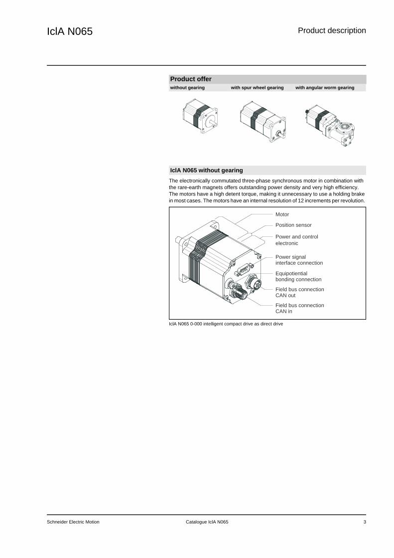
The electronically commutated three-phase synchronous motor in combination with the rare-earth magnets offers outstanding power density and very high efficiency. The motors have a high detent torque, making it unnecessary to use a holding brake in most cases. The motors have an internal resolution of 12 increments per revolution.
IclA N065 0-000 intelligent compact drive as direct drive
Product offerwithout gearing with spur wheel gearing with angular worm gearing
IclA N065 without gearing
Motor
Position sensor
Power and controlelectronic
Power signal interface connection
Equipotientialbonding connection
Field bus connectionCAN out
Field bus connectionCAN in
Schneider Electric Motion Catalogue IclA N065 3
IclA N065Product description
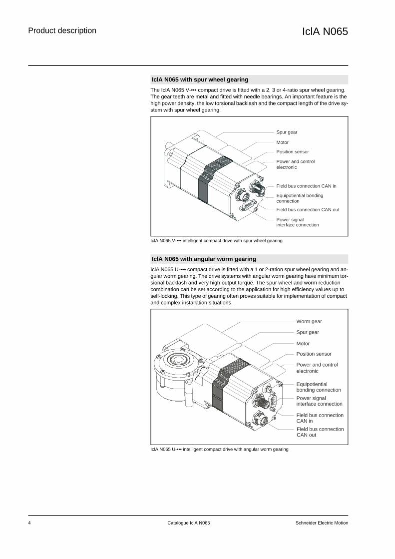
The IclA N065 V-••• compact drive is fitted with a 2, 3 or 4-ratio spur wheel gearing. The gear teeth are metal and fitted with needle bearings. An important feature is the high power density, the low torsional backlash and the compact length of the drive sy-stem with spur wheel gearing.
IclA N065 V-••• intelligent compact drive with spur wheel gearing
IclA N065 U-••• compact drive is fitted with a 1 or 2-ration spur wheel gearing and an-gular worm gearing. The drive systems with angular worm gearing have minimum tor-sional backlash and very high output torque. The spur wheel and worm reduction combination can be set according to the application for high efficiency values up to self-locking. This type of gearing often proves suitable for implementation of compact and complex installation situations.
IclA N065 U-••• intelligent compact drive with angular worm gearing
IclA N065 with spur wheel gearing
IclA N065 with angular worm gearing
Motor
Power and controlelectronic
Power signal interface connection
Equipotiential bonding connection
Field bus connection CAN out
Field bus connection CAN in
Position sensor
Spur gear
Worm gear
Motor
Position sensor
Power and controlelectronic
Spur gear
Power signal interface connection
Equipotientialbonding connection
Field bus connectionCAN inField bus connectionCAN out
4 Catalogue IclA N065 Schneider Electric Motion

IclA N065 Product description
Connections of the IclA N065 intelligent compact drives:• Signal interface• Connection for equipotential bonding conductor• CAN fieldbus interface
The signal interface is a 9-pin SubD connector and has the following functions:• supply voltage connection• power for manual mode control signals• connection for enable signal• power connection for signal interface
CAN in inputThe "CAN in" input for the CAN fieldbus is a 5-pin M12 flange connector.
CAN out outputThe compact drive also has a 5-pin M12 flange socket for networking the CAN field-bus. Additional network devices can be connected here.
Networking of four IclA N065 with a PLC
ConnectionsOverview
CAN out
CAN in
Power signal interface connection
connection
Equipotiential bonding
Field bus connection
Field bus connection
Signal interface
CAN fieldbus interface
Socket
Plug
Terminating resistor
(see accessories)
PLC(with terminating resistor)
Schneider Electric Motion Catalogue IclA N065 5
IclA N065Product description
6 Catalogue IclA N065 Schneider Electric Motion

IclA N065 Functions
The following operating modes can be set with signals:• Jog
The following operating modes can be set via fieldbus:• Jog• Homing• Profile position• Speed control mode
Jogging via signalsIn manual operation using signals the compact drive moves at an adjustable speed within the referenced work stroke. The direction of movement and the jog or conti-nuous operation operating modes are preset over two signal inputs.
Jog via fieldbusIn manual operation via fieldbus the compact drive can also be moved clockwise or counterclockwise within the homing range. The direction of motion and the speed are specified over the fieldbus.
The compact drive must be homed for "Manual Operation" and "Profile Position" ope-rating modes. The homing specifies three limit switch points for every direction of mo-tion. The compact drive monitors them continuously for overshoot. A homing is also retained after switching the compact drive off and on if the drive was not rotated when the power was off.
In "profile position" operating mode the homed compact drive can be moved from point A to point B. A trapeze profile is specified; application-specific trapeze profiles with values for final speed with acceleration and deceleration ramps can be saved in nine additional parameter sets.
In "speed control" operating mode travel commands are processed via the fieldbus. In this operating mode the drive requires homing if the software limit switches are used. The function of the software limit switches can be disabled by setting parame-ters of all software limit switches to the minimum or maximum range limits. The com-pact drive can then also be moved in speed control mode without homing. The refe-rence value of a travel command is the set speed of the drive movement. The acce-leration and braking ramp is parameterised and can be adjusted for the specific ap-plication.
FunctionsOperating modesOverview
Jog
Homing
Profile position
Speed control mode
Schneider Electric Motion Catalogue IclA N065 7
IclA N065Functions
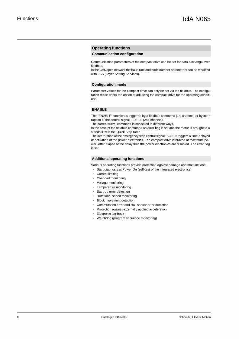
Communication parameters of the compact drive can be set for data exchange over fieldbus. In the CANopen network the baud rate and node number parameters can be modified with LSS (Layer Setting Services).
Parameter values for the compact drive can only be set via the fieldbus. The configu-ration mode offers the option of adjusting the compact drive for the operating conditi-ons.
The "ENABLE" function is triggered by a fieldbus command (1st channel) or by inter-ruption of the control signal ENABLE (2nd channel). The current travel command is cancelled in different ways. In the case of the fieldbus command an error flag is set and the motor is brought to a standstill with the Quick Stop ramp.The interruption of the emergency stop control signal ENABLE triggers a time-delayed deactivation of the power electronics. The compact drive is braked at maximum po-wer. After elapse of the delay time the power electronics are disabled. The error flag is set.
Various operating functions provide protection against damage and malfunctions:• Start diagnosis at Power On (self-test of the integrated electronics)• Current limiting• Overload monitoring• Voltage monitoring• Temperature monitoring• Start-up error detection• Rotational speed monitoring• Block movement detection• Commutation error and Hall sensor error detection• Protection against externally applied acceleration• Electronic log-book• Watchdog (program sequence monitoring)
Operating functionsCommunication configuration
Configuration mode
ENABLE
Additional operating functions
8 Catalogue IclA N065 Schneider Electric Motion
IclA N065 IclA N065 without gearingTechnical data
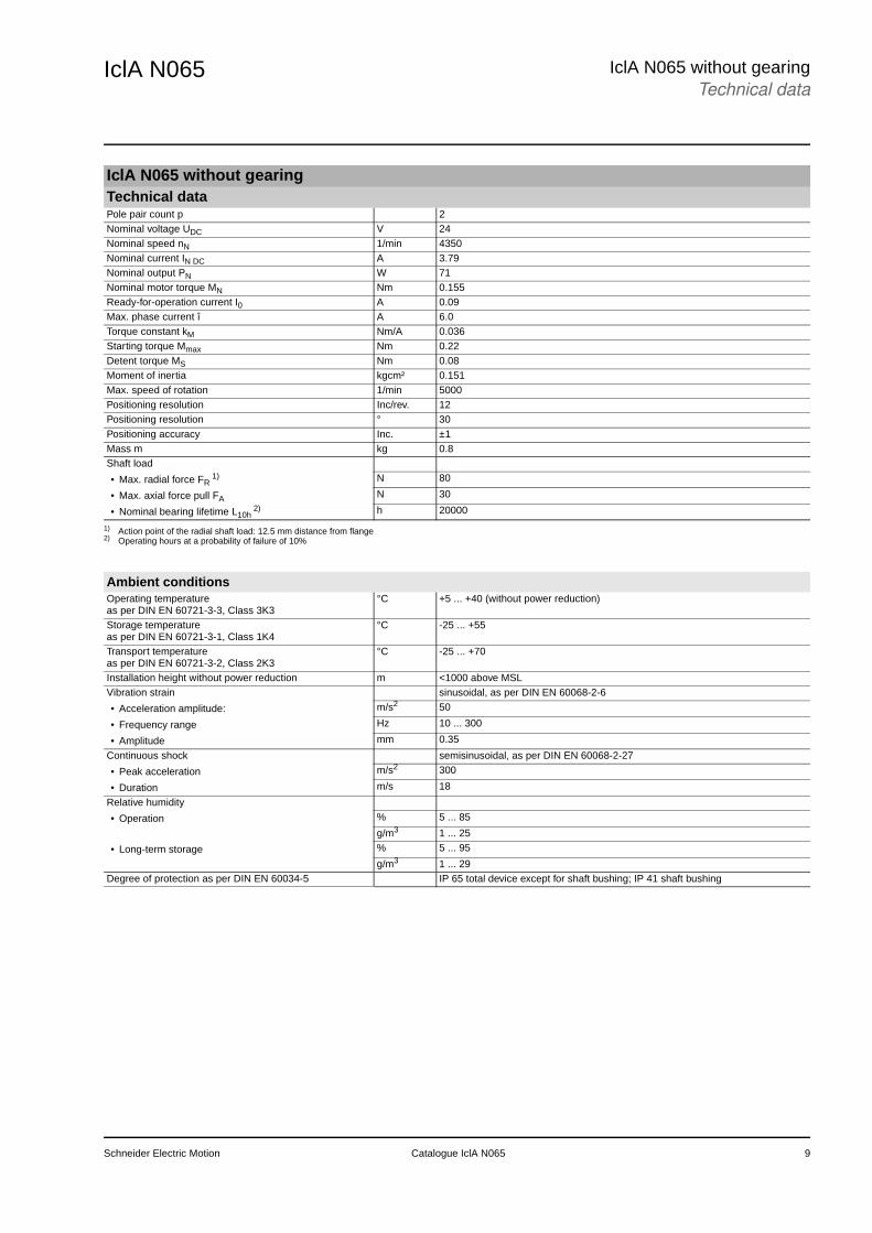
IclA N065 without gearingTechnical dataPole pair count p 2Nominal voltage UDC V 24Nominal speed nN 1/min 4350Nominal current IN DC A 3.79Nominal output PN W 71Nominal motor torque MN Nm 0.155Ready-for-operation current I0 A 0.09Max. phase current î A 6.0Torque constant kM Nm/A 0.036Starting torque Mmax Nm 0.22Detent torque MS Nm 0.08Moment of inertia kgcm² 0.151Max. speed of rotation 1/min 5000Positioning resolution Inc/rev. 12Positioning resolution ° 30Positioning accuracy Inc. ±1Mass m kg 0.8Shaft load
• Max. radial force FR1) N 80
• Max. axial force pull FA N 30
• Nominal bearing lifetime L10h2) h 20000
1) Action point of the radial shaft load: 12.5 mm distance from flange2) Operating hours at a probability of failure of 10%
Ambient conditionsOperating temperature as per DIN EN 60721-3-3, Class 3K3
°C +5 ... +40 (without power reduction)
Storage temperature as per DIN EN 60721-3-1, Class 1K4
°C -25 ... +55
Transport temperatureas per DIN EN 60721-3-2, Class 2K3
°C -25 ... +70
Installation height without power reduction m <1000 above MSLVibration strain sinusoidal, as per DIN EN 60068-2-6
• Acceleration amplitude: m/s2 50
• Frequency range Hz 10 ... 300
• Amplitude mm 0.35
Continuous shock semisinusoidal, as per DIN EN 60068-2-27
• Peak acceleration m/s2 300
• Duration m/s 18
Relative humidity
• Operation % 5 ... 85
g/m3 1 ... 25
• Long-term storage % 5 ... 95
g/m3 1 ... 29Degree of protection as per DIN EN 60034-5 IP 65 total device except for shaft bushing; IP 41 shaft bushing
Schneider Electric Motion Catalogue IclA N065 9

IclA N065IclA N065 without gearingTechnical data
Characteristic curvesIclA N065 DC024 without gearing
0 1000 2000 3000 4000 5000
0,00
0,05
0,10
0,15
0,20
0,25
torq
ue [N
m]
motor speed [rpm]
0
1
2
3
4
5
3 A
5 A
6 A
c
onsum
ption c
urr
ent [A
]
Electrical interfacesPower supply reverse-polarity-protectedNominal power supply range VDC 19.2 ... 28.8Ripple at nominal voltage V ≤3.6Inrush current A Load current for DC bus capacity (500 µF)24V signal interface 4 signal inputs, 0VDC internally connected with 0VDC supply voltage, reverse-
polarity-protectedPermissible low level V / mA ≤4.5 / ≤0.7Permissible high level V / mA ≥15 / ≥2Admissible voltage range V 0 ... 30Signal input debounce time ms 50 (in manual mode)
without debounce (homing movement switch and end position sensors)CANopen fieldbus interface CANIn/CANOut - topologySignal inputs/outputs according to ISO 11898, no galvanic isolationTransmission rate kBaud 10 / 20 / 50 / 100 / 125 / 250 / 500 / 800 / 1000Transmission protocol
• Communications profile DS301 V4.02
• Device profile DSP 402 V2.0
10 Katalog IclA N065 Schneider Electric Motion

IclA N065 IclA N065 without gearingDimensional drawings
Dimensional drawing of IclA N065 0-000 without gearing
Dimensional drawings
R7
ø8 j6
centringø40 h8 (2 high)
A
4 x pass hole ø4,3
Schneider Electric Motion Catalogue IclA N065 11

IclA N065IclA N065 with spur wheel gearingTechnical data
IclA N065 with spur wheel gearingTechnical datawith spur wheel gearing ... V-007 V-018 V-038 V-054 V-115Nominal voltage V 24 24 24 24 24Nominal speed 1/min 4000 4000 4000 4000 4000Nominal output torque Nm 1.1 2.7 5.8 7.9 12.3Nominal output speed 1/min 586 225 107 73 35Nominal output W 68 64 64 61 45Nominal current A 4.43 4.43 4.43 4.43 3.16Ready-for-operation current A 0.09 0.09 0.09 0.09 0.09Max. phase current A 6.0 6.0 6.0 6.0 4.5Maximum speed 1/min 733 281 133 92 44Gear speeds 2 3 3 4 4Gear efficiency 0.90 0.86 0.86 0.81 0.81Ratio 430: 63 160: 9 75: 2 490: 9 3675: 32Torque constant Nm/A 0.036 0.036 0.036 0.036 0.036Starting torque Nm 1.3 3.3 6.9 9.6 15.2Moment of inertia 1) g cm² 151 151 151 151 151Moment of inertia 2) kg m² 0.0007 0.0048 0.0212 0.0448 0.1992Detent torque Nm 0.5 1.3 2.8 4.1 8.6Positioning resolution Inc./rev 12 12 12 12 12Positioning resolution ° 4.40 1.69 0.80 0.55 0.26Positioning accuracy Inc. ±1 ±1 ±1 ±1 ±1Mass kg 1.1 1.2 1.2 1.2 1.2Number of pole pairs 2 2 2 2 2Torsional backlash ° ≤1.5 ≤1.0 ≤1.0 ≤1.0 ≤1.0Shaft load
• Short-term operation
- Max. radial force 3) N 200 200 200 200 200
- Max. axial force N 80 80 80 80 80
- Nominal service life L10h4) h 2500 2500 2500 2500 2500
• Continuous operation
- Max. radial force 3) N 200 200 200 200 200
- Max. axial force N 10 10 10 10 10
- Nominal service life L10h4) h 15000 15000 15000 15000 15000
1) With reference to motor shaft2) with reference to gearing output shaft3) action point of the radial shaft load: 12.5 mm distance from flange4) operating hours at a probability of failure of 10%
Ambient conditionsOperating temperature as per DIN EN 60721-3-3, Class 3K3
°C +5 ... +40 (without power reduction)
Storage temperature as per DIN EN 60721-3-1, Class 1K4
°C -25 ... +55
Transport temperatureas per DIN EN 60721-3-2, Class 2K3
°C -25 ... +70
Installation height without power reduction m <1000 above MSLVibration strain sinusoidal, as per DIN EN 60068-2-6
• Acceleration amplitude: m/s2 50
• Frequency range Hz 10 ... 300
• Amplitude mm 0.35
Continuous shock semisinusoidal, as per DIN EN 60068-2-27
• Peak acceleration m/s2 300
• Duration m/s 18
Relative humidity
• Operation % 5 ... 85
g/m3 1 ... 25
• Long-term storage % 5 ... 95
g/m3 1 ... 29Degree of protection as per DIN EN 60034-5 IP 65 total device except for shaft bushing; IP 54 shaft bushing
12 Katalog IclA N065 Schneider Electric Motion

IclA N065 IclA N065 with spur wheel gearingTechnical data
Characteristic curvesIclA N065 DC024 with spur wheel gearing V-007 IclA N065 DC024 with spur wheel gearing V-018
IclA N065 DC024 with spur wheel gearing V-038 IclA N065 DC024 with spur wheel gearing V-054
IclA N065 DC024 with spur wheel gearing V-115
0 1000 2000 3000 4000 5000
0,0
0,4
0,8
1,2
1,6
2,0
0,0 146,5 293,0 439,6 586,1 732,6
0
1
2
3
4
5
output speed [rpm]
to
rqu
e [N
m]
motor speed [rpm] c
on
su
mp
tio
n c
urr
en
t [A
]
0 1000 2000 3000 4000 5000
0,0
0,8
1,6
2,4
3,2
4,0
0,0 56,2 112,5 168,7 225,0 281,2
0
1
2
3
4
5
output speed [rpm]
to
rqu
e [N
m]
motor speed [rpm]
c
on
su
mp
tio
n c
urr
en
t [A
]
0 1000 2000 3000 4000 5000
0,0
1,6
3,2
4,8
6,4
8,0
0,0 26,7 53,3 80,0 106,7 133,3
0
1
2
3
4
5
output speed [rpm]
t
orq
ue
[N
m]
motor speed [rpm]
c
on
su
mp
tio
n c
urr
en
t [A
]
0 1000 2000 3000 4000 5000
0,0
2,5
5,0
7,5
10,0
12,5
0,0 18,4 36,7 55,1 73,5 91,8
0
1
2
3
4
5
output speed [rpm]
t
orq
ue
[N
m]
motor speed [rpm]
c
on
su
mp
tio
n c
urr
en
t [A
]
0 1000 2000 3000 4000 5000
0,0
4,0
8,0
12,0
16,0
20,0
0,0 8,7 17,4 26,1 34,8 43,5
0
1
2
3
4
5
output speed [rpm]
torq
ue [N
m]
motor speed [rpm]
c
onsum
ption c
urr
ent [A
]
Schneider Electric Motion Katalog IclA N065 13

IclA N065IclA N065 with spur wheel gearingDimensional drawings
Dimensional drawing of IclA N065 DC024 V-••• with spur wheel gearing
Electrical interfacesPower supply reverse-polarity-protectedNominal power supply range VDC 19.2 ... 28.8Ripple at nominal voltage V ≤3.6Inrush current A Load current for DC bus capacity (500 µF)24V signal interface 4 signal inputs, 0VDC internally connected with 0VDC supply voltage, reverse-
polarity-protectedPermissible low level V / mA ≤4.5 / ≤0.7Permissible high level V / mA ≥15 / ≥2Admissible voltage range V 0 ... 30Signal input debounce time ms 50 (in manual mode)
without debounce (homing movement switch and end position sensors)CANopen fieldbus interface CANIn/CANOut - topologySignal inputs/outputs according to ISO 11898, no galvanic isolationTransmission rate kBaud 10 / 20 / 50 / 100 / 125 / 250 / 500 / 800 / 1000Transmission protocol
• Communications profile DS301 V4.02
• Device profile DSP 402 V2.0
Dimensional drawings
A
Ø3x3x16 10 h8fit-in key DIN 6885
centringØ16 h8 (4 high)
R7
13
13
4 x pass hole Ø4.3
131.6
17.5
4.3
14
6
14 Katalog IclA N065 Schneider Electric Motion

IclA N065 IclA N065 with angular worm gearingTechnical data
IclA N065 with angular worm gearingTechnical datawith angular worm gearing ... U-024 U-054 U-092 U-115Nominal voltage V 24 24 24 24Nominal speed 1/min 4000 4000 4000 4000Nominal output torque Nm 2.6 6.0 9.2 10.6Nominal output speed 1/min 168 75 44 35Nominal output W 46 47 42 39Nominal current A 4.43 4.43 4.43 4.43Ready-for-operation current A 0.09 0.09 0.09 0.09Max. phase current A 6.0 6.0 6.0 6.0Maximum speed 1/min 189 93 54 44Gear speeds 2 3 3 3Gear efficiency 0.61 0.62 0.56 0.51Ratio 525: 22 1715: 32 735: 8 3675: 32Torque constant Nm/A 0.036 0.036 0.036 0.036Starting torque Nm 2.2 5.0 7.8 8.9Moment of inertia 1) g cm² 165 150 150 150Moment of inertia 2) kg m² 0.009 0.043 0.127 0.198Detent torque Nm 2.9 6.5 12.3 16.7Positioning resolution Inc./rev 12 12 12 12Positioning resolution ° 1.26 0.56 0.33 0.26Positioning accuracy Inc. ±1 ±1 ±1 ±1Mass kg 1.7 1.7 1.7 1.7Number of pole pairs 2 2 2 2Torsional backlash ° ≤1.5 ≤1.0 ≤1.0 ≤1.0Shaft load
• Max. radial force N 200 200 200 200
• Max. axial force N 80 80 80 80
• Nominal service life L10h3) h 9000 9000 6000 3000
1) With reference to motor shaft2) With reference to gearing output shaft3) Operating hours at a probability of failure of 10%
Ambient conditionsOperating temperature as per DIN EN 60721-3-3, Class 3K3
°C +5 ... +40 (without power reduction)
Storage temperature as per DIN EN 60721-3-1, Class 1K4
°C -25 ... +55
Transport temperatureas per DIN EN 60721-3-2, Class 2K3
°C -25 ... +70
Installation height without power reduction m <1000 above MSLVibration strain sinusoidal, as per DIN EN 60068-2-6
• Acceleration amplitude: m/s2 50
• Frequency range Hz 10 ... 300
• Amplitude mm 0.35
Continuous shock semisinusoidal, as per DIN EN 60068-2-27
• Peak acceleration m/s2 300
• Duration m/s 18
Relative humidity
• Operation % 5 ... 85
g/m3 1 ... 25
• Long-term storage % 5 ... 95
g/m3 1 ... 29Degree of protection as per DIN EN 60034-5 IP 65 total device
Schneider Electric Motion Catalogue IclA N065 15
IclA N065IclA N065 with angular worm gearingTechnical data
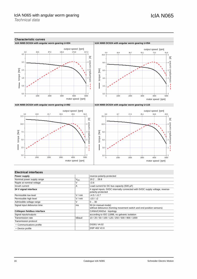
Characteristic curvesIclA N065 DC024 with angular worm gearing U-024 IclA N065 DC024 with angular worm gearing U-054
IclA N065 DC024 with angular worm gearing U-092 IclA N065 DC024 with angular worm gearing U-115
0 1000 2000 3000 4000 5000
0,0
0,8
1,6
2,4
3,2
4,0
0,0 43,5 87,0 130,4 173,9 217,4
0
1
2
3
4
5
output speed [rpm]
to
rqu
e [N
m]
motor speed [rpm]
c
on
su
mp
tio
n c
urr
en
t [A
]
0 1000 2000 3000 4000 5000
0,0
2,0
4,0
6,0
8,0
10,0
0,0 18,4 36,7 55,1 73,5 91,8
0
1
2
3
4
5
output speed [rpm]
t
orq
ue
[N
m]
motor speed [rpm]
c
on
su
mp
tio
n c
urr
en
t [A
]
0 1000 2000 3000 4000 5000
0,0
2,5
5,0
7,5
10,0
12,5
0,0 10,9 21,7 32,6 43,5 54,3
0
1
2
3
4
5
output speed [rpm]
torq
ue [N
m]
motor speed [rpm]
c
onsum
ption c
urr
ent [A
]
0 1000 2000 3000 4000 5000
0,0
3,0
6,0
9,0
12,0
15,0
0,0 8,7 17,4 26,1 34,8 43,5
0
1
2
3
4
5
output speed [rpm]
torq
ue [N
m]
motor speed [rpm]
c
onsum
ption c
urr
ent [A
]Electrical interfacesPower supply reverse-polarity-protectedNominal power supply range VDC 19.2 ... 28.8Ripple at nominal voltage V ≤3.6Inrush current A Load current for DC bus capacity (500 µF)24 V signal interface 4 signal inputs, 0VDC internally connected with 0VDC supply voltage, reverse-
polarity-protectedPermissible low level V / mA ≤4.5 / ≤0.7Permissible high level V / mA ≥15 / ≥2Admissible voltage range V 0 ... 30Signal input debounce time ms 50 (in manual mode)
without debounce (homing movement switch and end position sensors)CANopen fieldbus interface CANIn/CANOut - topologySignal inputs/outputs according to ISO 11898, no galvanic isolationTransmission rate kBaud 10 / 20 / 50 / 100 / 125 / 250 / 500 / 800 / 1000Transmission protocol
• Communications profile DS301 V4.02
• Device profile DSP 402 V2.0
16 Catalogue IclA N065 Schneider Electric Motion

IclA N065 IclA N065 with angular worm gearingDimensional drawings
Dimensional drawing of IclA N065 DC024 U-••• with angular worm gearing
Dimensional drawings
2
28
36
34
34
A
46.9
4 P9
R32
R 9
8h8
Ø46pitch circle-Ø
centringØ36 h8 (3,5 high)
Ø12 F8
lock againstrotation
34
2 x pass hole Ø5.3
6 x tappedblind holes
self-furrowingscrews M3
DIN 7500 (10 deep)
4.3
17.5 14
184.3139.381.6
�65
50.6
14.595
13.8
14.595
Schneider Electric Motion Catalogue IclA N065 17

18 Catalogue IclA N065 Schneider Electric Motion
IclA N065Type code
Type codeExample: IclA N06 5 / 2 DC024 V-007 K CAN 00Product familyIntelligent Compact Drive IclA
IclA N06 5 / 2 DC024 V-007 K CAN 00
Size (flange)N06 = 66 mm
IclA N06 5 / 2 DC024 V-007 K CAN 00
Motor package length5 = 18 mm
IclA N06 5 / 2 DC024 V-007 K CAN 00
not used IclA N06 5 / 2 DC024 V-007 K CAN 00Pole pair count2
IclA N06 5 / 2 DC024 V-007 K CAN 00
Supply voltageDC024 = 24VDC
IclA N06 5 / 2 DC024 V-007 K CAN 00
Supply voltageDC024 = 24VDC
IclA N06 5 / 2 DC024 V-007 K CAN 00
Gearbox type Gear ratio IclA N06 5 / 2 DC024 V-007 K CAN 000- without gearing 0-000V - with spur wheel gearing 430:63
160:9 75:2 490:9 3675:32
V-007V-018V-038V-054V-118
U - with worm gearing 525:22 1715:32 735:8 3675:32
U-024U-054U-092U-115
Shaft type R = round, smooth shaftK = parallel key (spur wheel gearing only)F = D-shaped shaft (spur wheel gearing only)
IclA N06 5 / 2 DC024 V-007 K CAN 00
Communication interfaceCAN = CANopen
IclA N06 5 / 2 DC024 V-007 K CAN 00
Reserve00
IclA N06 5 / 2 DC024 V-007 K CAN 00

IclA N065 AccessoriesSoftware and documentation
The IclA CCT commissioning software supports you when commissioning the IclA N065.You will require a CAN interface board from IXXAT Automation, a hardware driver for Windows and a licence for the IXXAT CANopen master API, Version 4.0 or compati-ble, to be able to start the program.
System requirementsWindows NT4 SP3; Windows XP or higherPentium 233 MHz or higher32 MB RAM; 10 MB free hard-disk space
SourceThe IclA CCT PC commissioning software and the manuals IclA N065 and Fieldbus IclA CANopen N065 can be found atwww.schneider-electric-motion.com/download
AccessoriesSoftware and documentationIclA CCT commissioning software
Signal interface
The signal interface is a 9-pin SubD connector supplied by FCT electronic GmbH.
Order dataDesignation Description Order numberIclA cable for signal interface IP65 with 9-pin sub-D socket for connection to signal inter-
face5m 590000002410m 590000003420m 5900000035
Accessories for signal interface of IclA N065 are supplied by the following company. When ordering please note the degree of protection of the compact drive (IP 65 recommended):
FCT electronic GmbHSchatzbogen 13D-81829 MunichTelephone: +49 (0) 89 420004-0Fax: +49 (0) 89 420004-10Internet: http://www.fct-electronic.de
CAN fieldbus interfaceThe CAN fieldbus interface consists of a 5-pin M12 flange connector (CAN in) and a 5-pin M12 flange socket (CAN out) supplied by Franz Binder GmbH. If several IclA N065 compact drives are networked with a PLC, a terminating resistor is required. This resistor can be ordered from Hans Turck. Accessories for the fieldbus interface of the IclA N065 are supplied by the following companies:
Franz Binder GmbH & Co. elektrische Bauelemente KGRötelstraße 27D-74172 NeckarsulmTelephone: +49 (0) 7132 325 - 0Fax: +49 (0) 7132 325 - 150E-mail: [email protected]: http://www.binder-connector.de
Hans Turck GmbH & Co. KGWitzlebenstraße 7D-45472 Mühlheim an der RuhrTelephone: +49 (0) 208 4952-0Fax: +49 (0) 208 4952-264E-mail: [email protected]: http://www.turck.com
Schneider Electric Motion Catalogue IclA N065 19

IclA N065AccessoriesGBX planetary gearboxes
In many cases the axis controller requires the use of a planetary gearbox foradjustment of speed of rotation and torque; the accuracy required by the applicationmust be maintained.
Schneider Electric Motion has chosen to use GBX 40 gearbox (made by Neugart) with the IclA N065. These gearbox are lubricated for life and aredesigned for applications which are not susceptible to mechanical backlash.The fact that their use in combination with IclA N065 has been fully verifiedand that they are easily assembled, ensures simple, risk-free operation.
The GBX 40 gearboxes are offered in 4 reduction ratios (16:1, 40:1, 60:1, 120:1), see table below.
The values for the continuous torque and the peak torque at standstill which areavailable at the output shaft, are calculated by multiplying the motor characteristicswith the gear ratio and the effi ciency of the gearing (0.94 or 0.90 depending on thereduction ratio).
GBX planetary gearboxesPresentation
Technical data GBX 40Version Planetary gearbox with straight teethBacklash 16:1 ... 40:1 arcmin < 28
60:1 ... 120:1 < 30Torsional rigidity 16:1 ... 40:1 Nm/ arcmin 1.1
60:1 ... 120:1 1.0Noise level 1) 58Casing Steel, black surfaceShaft material C 45Shaft output dust and dump protection IP 54Lubrication Lubricated lifeAverage service life 2) h 30000Mounting position Any positionOperating temperature °C -25 ... +90Effi ciency 16:1 ... 40:1 0.94
60:1 ... 120:1 0.90Maximum permitted radialforce 2) 3)
L10h = 10000 h N 200L10h = 30000 h N 160
Maximum permitted axialforce 2)
L10h = 10000 h N 200L10h = 30000 h N 160
Moment of inertia ofgearbox
16:1 kg cm2 0.02240:1 kg cm2 0.01660:1 kg cm2 0.029120:1 kg cm2 0.029
Continuous outputtorque 2)
16:1 Nm 2040:1 Nm 1860:1 Nm 20120:1 Nm 18
Maximum output torque 2) 16:1 Nm 3240:1 Nm 2960:1 Nm 32120:1 Nm 29
1) Value measured at a distance of 1 m, at no-load for a servo motor speed of 3000 rpm and a reduction ratio of 5:1.2) Values given for an output shaft speed of 100 rpm in S1 mode (cyclic ratio = 1) on electrical machines for an ambient temperature of 30 °C.3) Force applied at mid-distance from the output shaft.
20 Catalogue IclA N065 Schneider Electric Motion
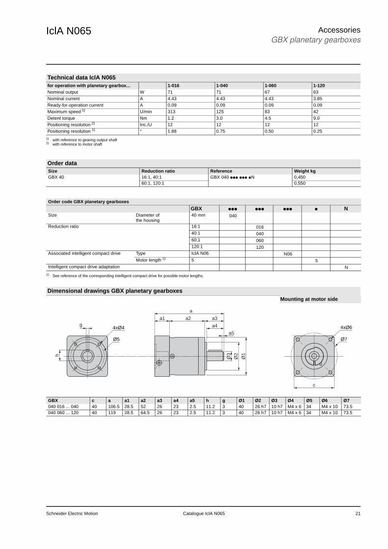
IclA N065 AccessoriesGBX planetary gearboxes
Technical data IclA N065for operation with planetary gearbox... 1-016 1-040 1-060 1-120Nominal output W 71 71 67 63Nominal current A 4.43 4.43 4.43 3.85Ready-for-operation current A 0.09 0.09 0.09 0.09Maximum speed 1) U/min 313 125 83 42Detent torque Nm 1.2 3.0 4.5 9.0Positioning resolution 2) Inc./U 12 12 12 12Positioning resolution 1) ° 1.88 0.75 0.50 0.25
1) with reference to gearing output shaft2) with reference to motor shaft
Order dataSize Reduction ratio Reference Weight kgGBX 40 16:1, 40:1 GBX 040 ppp ppp pN 0,450
60:1, 120:1 0,550
Order code GBX planetary gearboxes
GBX ppp ppp ppp p NSize Diameter of
the housing40 mm 040
Reduction ratio 16:1 01640:1 04060:1 060120:1 120
Associated intelligent compact drive Type IclA N06 N06Motor length 1) 5 5
Intelligent compact drive adaptation N
1) See reference of the corresponding intelligent compact drive for possible motor lengths.
Dimensional drawings GBX planetary gearboxesMounting at motor side
4xØ6
a1 a2 a3
a4
Ø3
Ø2
Ø1
a5
a
Ø7
g4xØ4
h
Ø5
c
GBX c a a1 a2 a3 a4 a5 h g Ø1 Ø2 Ø3 Ø4 Ø5 Ø6 Ø7040 016 ... 040 40 106.5 28.5 52 26 23 2.5 11.2 3 40 26 h7 10 h7 M4 x 6 34 M4 x 10 73.5040 060 ... 120 40 119 28.5 64.5 26 23 2.5 11.2 3 40 26 h7 10 h7 M4 x 6 34 M4 x 10 73.5
Schneider Electric Motion Catalogue IclA N065 21
IclA N065AccessoriesGBX planetary gearboxes
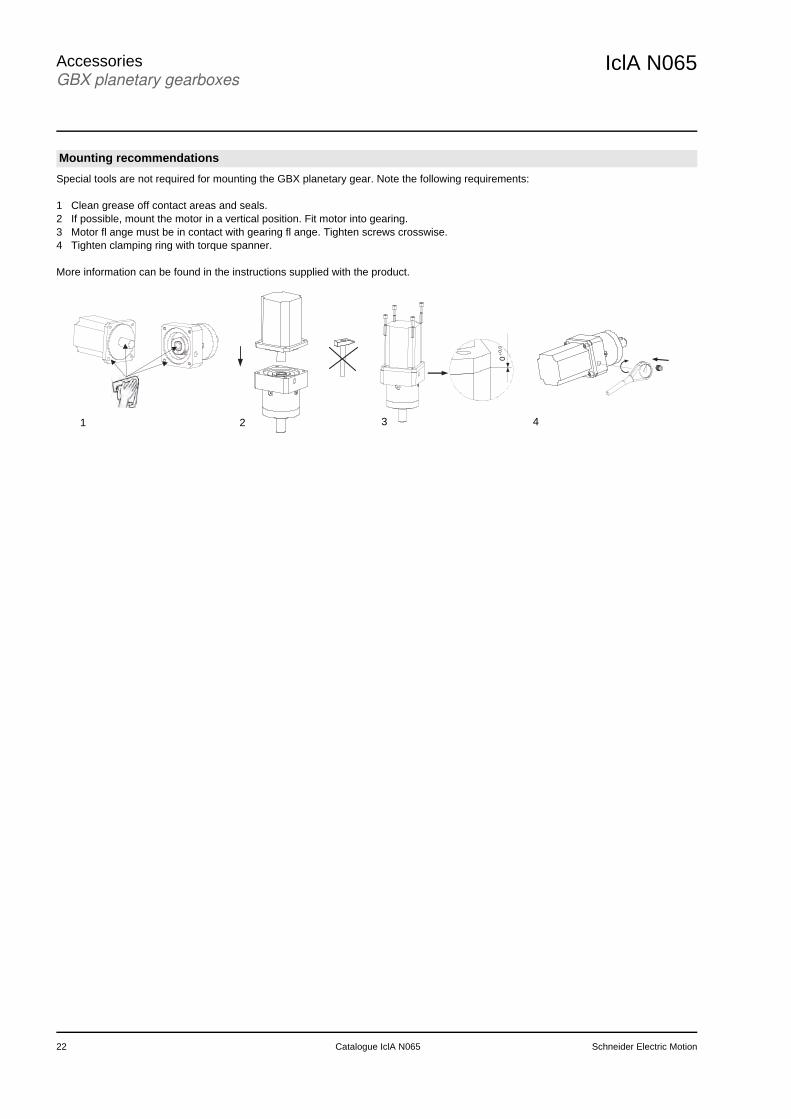
Special tools are not required for mounting the GBX planetary gear. Note the following requirements:
1 Clean grease off contact areas and seals.2 If possible, mount the motor in a vertical position. Fit motor into gearing.3 Motor fl ange must be in contact with gearing fl ange. Tighten screws crosswise.4 Tighten clamping ring with torque spanner.
More information can be found in the instructions supplied with the product.
Mounting recommendations
0+0,0
1 2 3 4
22 Catalogue IclA N065 Schneider Electric Motion

IclA N065 AppendixConversion tables
Example for conversion:Conversion of a 10 inch length measurement into metres. Look for the entry “in” (= inch) in the “Length” table in the left column and the entry “m” (= metre) in the hea-der. The table cell at the point of intersection of the column and the row will show the conversion factor: “0.0254”. Multiply 10 inches by 0.0254 and you will get the value in metres: 10 in x 0.0254 = 0.254 m.
Conversion tablesRotor inertia
lb·in2 lb·ft2 lb·in·s2 lb·ft·s2
slug·ft2kg·cm2 kg·cm·s2 g·cm2 g·cm·s2 oz·in2 oz·in·s2
lb·in2 – 6.94 x 10⁻³ 2.59 x 10⁻³ 2.15 x 10⁻⁴ 2.926 2.98 x 10⁻³ 2.92 x 10³ 2.984 16 4.14 x 10⁻²
lb·ft2 144 – 0.3729 3.10 x 10⁻² 421.40 0.4297 4.21 x 10⁵ 429.71 2304 5.967lb·in·s2 386.08 2.681 – 8.33 x 10⁻² 1.129 x 10³ 1.152 1.129 x 10⁶ 1.152 x 10³ 6.177 x 10³ 16lb·ft·s2
slug·ft24.63 x 103 32.17 12 – 1.35 x 10⁴ 13.825 1.355 x 10⁷ 1.38 x 10⁴ 7.41 x 10⁴ 192
kg·cm2 0.3417 2.37 x 10⁻³ 8.85 x 10⁻⁴ 7.37 x 10⁻⁶ – 1.019 x 10⁻³ 1000 1.019 5.46 1.41 x 10⁻²
kg·cm·s2 335.1 2.327 0.8679 7.23 x 10⁻² 980.66 – 9.8 x 10⁵ 1000 5.36 x 10³ 13.887g·cm2 3.417 x 10⁻⁴ 2.37 x 10⁻⁶ 8.85 x 10⁻⁷ 7.37 x 10⁻⁸ 1 x 10⁻³ 1.01 x 10⁻⁶ – 1.01 x 10⁻³ 5.46 x 10⁻³ 1.41 x 10⁻⁶
g·cm·s2 0.335 2.32 x 10⁻³ 8.67 x 10⁻⁴ 7.23 x 10⁻⁵ 0.9806 1 x 10⁻³ 980.6 – 5.36 1.38 x 10⁻²
oz·in2 0.0625 4.3 x 10⁻⁴ 1.61 x 10⁻⁶ 1.34 x 10⁻⁶ 0.182 1.86 x 10⁻⁴ 182.9 0.186 – 2.59 x 10⁻³
oz·in·s2 24.13 0.1675 6.25 x 10⁻² 5.20 x 10⁻³ 70.615 7.20 x 10⁻² 7.06 x 10⁴ 72 386.08 –
Torquelb·in lb·ft oz·in Nm kg·m kg·cm g·cm dyne·cm
lb·in – 8.333 x 10⁻² 16 0.113 1.152 x 10⁻² 1.152 1.152 x 10³ 1.129 x 10⁶
lb·ft 12 – 192 1.355 0.138 13.825 1.382 x 10⁴ 1.355 x 10⁷
oz·in 6.25 x 10⁻² 5.208 x 10⁻³ – 7.061 x 10⁻³ 7.200 x 10⁻⁴ 7.200 x 10⁻² 72.007 7.061 x 10⁴
Nm 8.850 0.737 141.612 – 0.102 10.197 1.019 x 10⁴ 1 x 10⁷
kg·m 86.796 7.233 1.388 x 10³ 9.806 – 100 1 x 10⁵ 9.806 x 10⁷
kg·cm 0.8679 7.233 x 10⁻² 13.877 9.806 x 10⁻² 10-2 – 1000 9.806 x 10⁵
g·cm 8.679 x 10⁻⁴ 7.233 x 10⁻⁵ 1.388 x 10⁻² 9.806 x 10⁻⁵ 1 x 10⁻⁵ 1 x 10⁻³ – 980.665dyne·cm 8.850 x 10⁻⁷ 7.375 x 10⁻⁸ 1.416 x 10⁻⁵ 10-7 1.019 x 10⁻⁸ 1.0197 x 10⁻⁶ 1.019 x 10⁻⁶ –
Power LengthH.P. W in ft yd m cm mm
H.P. – 745.7 in – 0.0833 0.028 0.0254 2.54 25.4W 1.31 x 10⁻³ – ft 12 – 0.333 0.3048 30.48 304.8
yd 36 3 – 0.914 91.44 914.4m 39.37 3.281 1.09 – 100 1000cm 0.3937 0.03281 1.09 x 10⁻² 0.01 – 10mm 0.03937 0.00328 1.09 x 10⁻³ 0.001 0.1 –
Rotation Weight1/min (rpm) rad/sec deg./sec lb oz slug kg g
1/min (rpm) – 0.105 6.0 lb – 16 0.0311 0.453592 453.592rad/sec 9.55 – 57.30 oz 6.35 x 10⁻² – 1.93 x 10⁻³ 0.028349 28.35deg./sec 0.167 1.745 x 10⁻² – slug 32.17 514.8 – 14.5939 1.459 x 10⁴
kg 2.20462 35.274 0.0685218 – 1000g 2.205 x 10⁻³ 3.527 x 10⁻³ 6.852 x 10⁻⁵ 0.001 –
Temperature Force°F °C lb oz gf dyne N
°F – (ϑ - 32) · 5/9 lb – 16 453.592 4.448 x 10⁵ 4.4482°C ϑ · 9/5 + 32 – oz 0.0625 – 28.35 2.780 x 10⁴ 0.27801
gf 2.205 x 10⁻³ 0.03527 – 980,665 N.A.dyne 2.248 x 10⁻⁶ 3.59 x 10⁻⁶ 1.02 x 10⁻³ – 0.0001N 0.22481 3.5967 N.A. 100,000 –
Schneider Electric Motion Catalogue IclA N065 23

24 Catalogue IclA N065 Schneider Electric Motion


Schneider Electric Motion Deutschland GmbH & Co. KG www.schneider-electric-motion.com
Breslauer Str. 777933 LahrGermany
Due to evolution of standards and equipment, the characteristics indicated in texts and images ofthis document do not constitute a commitment on our part without confirmation.Design: Schneider Electric MotionPhotos: Schneider Electric Motion