Intelligent Channel Bonding in 802.11n WLANs
14
1 Intelligent Channel Bonding in 802.11n WLANs Lara Deek†, Eduard Garcia-Villegas‡, Elizabeth Belding†, Sung-Ju Lee§, Kevin Almeroth† UC Santa Barbara†, UPC-BarcelonaTECH‡, Narus Inc.§ [email protected], [email protected], [email protected], [email protected], [email protected] Abstract—The IEEE 802.11n standard defines channel bonding that allows wireless devices to operate on 40MHz channels by doubling their bandwidth from standard 20MHz channels. Increasing channel width increases capacity, but it comes at the cost of decreased transmission range and greater susceptibility to interference. However, with the incorporation of Multiple-Input Multiple-Output (MIMO) technology in 802.11n, devices can now exploit the increased transmission rates from wider channels with minimal sacrifice to signal quality and range. The goal of our work is to identify the network factors that influence the performance of channel bonding in 802.11n networks and make intelligent channel bonding decisions. We discover that channel width selection should consider not only a link’s signal quality, but also the strength of neighboring links, their physical rates, and interferer load. We use our findings to design and implement a network detector that successfully identifies interference conditions that affect channel bonding decisions in 100% of our test cases. Our detector can form the foundation for more robust and accurate algorithms that can adapt bandwidth to variations in channel conditions. Our findings allows us to predict the impact of network conditions on performance and make channel bonding decisions that maximize throughput. Index Terms—IEEE 802.11n, Channel Bonding, Measurement, Performance, Experimentation. ✦ 1 I NTRODUCTION With the wide deployment of the IEEE 802.11n standard and with the upcoming 802.11ac, WLANs now have the option to operate over wider channels that achieve higher capacity. The standardized 802.11n technology supports up to 40MHz channels through channel bonding, where two 20MHz channels are combined into a single 40MHz channel. Although transmissions over 40MHz channels should provide advantages over 20MHz channels, perfor- mance benefits are largely influenced by the adopted an- tenna technology. With the incorporation of MIMO smart- antenna technology in 802.11n devices, problems faced by traditional Single-Input Single-Output (SISO) systems from channel bonding [1], [2] can now be mitigated [3], [4]. MIMO technologies in 802.11n promise new potential for channel bonding and higher transmission rates. Wider bandwidths are also faced with challenges. The IEEE 802.11n standard imposes a fixed maximum trans- mission power on devices. By doubling the channel width, SNR is effectively decreased by 3dB [5], and thus, reception errors increase [6]. Furthermore, wider bandwidths are more likely to suffer from frequency selective fading. A 40MHz channel, therefore, not only requires a stronger transmission power to achieve the same SNR but also a higher SNR to provide the same PER. That is, transmissions using channel bonding require a slightly stronger signal strength to provide the same reliability as that of a single 20MHz channel. This tradeoff between higher transmission rates and susceptibility to interference must be carefully understood in order to improve performance. The 802.11n standard itself gives no guidelines or recommendations on how to benefit from channel bonding [7]. Previous experimental studies on 802.11n provide valu- able insights into 802.11n features [5], [6], [8], [9], but fall short in effectively characterizing the opportunities for channel bonding in real-world WLAN settings, where interfering links co-exist. Furthermore, most existing work operates within the 2.4GHz ISM band [6], [8], [9], where channel constraints are too tight to effectively gauge the performance of channel bonding. In fact, it was shown that channel bonding in the 2.4GHz range poses more harm than benefits [1], [8], [10]. There is therefore a clear need to evaluate the behavior of and opportunities for channel bonding under a broader range of circumstances, where the benefits of channel bonding can truly be exploited: the 5GHz range. In fact, the emerging 802.11ac standard operates only on the 5GHz band for this very reason. Our previous work identified the usage conditions for channel bonding in 802.11n WLANs [11]. These usage terms allow for intelligent channel bonding decisions and efficient utilization of available spectrum. To this end, we first characterized the behavior of channel bonding through experimental studies. Experiments were performed in the 5GHz frequency range over a stationary 802.11n testbed deployed in a semi-open office environment. These experiments demonstrated the impact of network conditions and interference patterns on throughput performance with channel bonding. From our experiments, we discovered that na¨ ıve channel bonding decisions degrade performance.
Transcript of Intelligent Channel Bonding in 802.11n WLANs

1
Intelligent Channel Bondingin 802.11n WLANs
Lara Deek†, Eduard Garcia-Villegas‡, Elizabeth Belding†,
Sung-Ju Lee§, Kevin Almeroth†
UC Santa Barbara†, UPC-BarcelonaTECH‡, Narus Inc.§[email protected], [email protected], [email protected], [email protected],
Abstract—The IEEE 802.11n standard defines channel bonding that allows wireless devices to operate on 40MHz channels
by doubling their bandwidth from standard 20MHz channels. Increasing channel width increases capacity, but it comes at the
cost of decreased transmission range and greater susceptibility to interference. However, with the incorporation of Multiple-Input
Multiple-Output (MIMO) technology in 802.11n, devices can now exploit the increased transmission rates from wider channels
with minimal sacrifice to signal quality and range. The goal of our work is to identify the network factors that influence the
performance of channel bonding in 802.11n networks and make intelligent channel bonding decisions. We discover that channel
width selection should consider not only a link’s signal quality, but also the strength of neighboring links, their physical rates,
and interferer load. We use our findings to design and implement a network detector that successfully identifies interference
conditions that affect channel bonding decisions in 100% of our test cases. Our detector can form the foundation for more robust
and accurate algorithms that can adapt bandwidth to variations in channel conditions. Our findings allows us to predict the impact
of network conditions on performance and make channel bonding decisions that maximize throughput.
Index Terms—IEEE 802.11n, Channel Bonding, Measurement, Performance, Experimentation.
F
1 INTRODUCTION
With the wide deployment of the IEEE 802.11n standard
and with the upcoming 802.11ac, WLANs now have the
option to operate over wider channels that achieve higher
capacity. The standardized 802.11n technology supports
up to 40MHz channels through channel bonding, where
two 20MHz channels are combined into a single 40MHz
channel. Although transmissions over 40MHz channels
should provide advantages over 20MHz channels, perfor-
mance benefits are largely influenced by the adopted an-
tenna technology. With the incorporation of MIMO smart-
antenna technology in 802.11n devices, problems faced by
traditional Single-Input Single-Output (SISO) systems from
channel bonding [1], [2] can now be mitigated [3], [4].
MIMO technologies in 802.11n promise new potential for
channel bonding and higher transmission rates.
Wider bandwidths are also faced with challenges. The
IEEE 802.11n standard imposes a fixed maximum trans-
mission power on devices. By doubling the channel width,
SNR is effectively decreased by 3dB [5], and thus, reception
errors increase [6]. Furthermore, wider bandwidths are
more likely to suffer from frequency selective fading. A
40MHz channel, therefore, not only requires a stronger
transmission power to achieve the same SNR but also a
higher SNR to provide the same PER. That is, transmissions
using channel bonding require a slightly stronger signal
strength to provide the same reliability as that of a single
20MHz channel. This tradeoff between higher transmission
rates and susceptibility to interference must be carefully
understood in order to improve performance. The 802.11n
standard itself gives no guidelines or recommendations on
how to benefit from channel bonding [7].
Previous experimental studies on 802.11n provide valu-
able insights into 802.11n features [5], [6], [8], [9], but
fall short in effectively characterizing the opportunities
for channel bonding in real-world WLAN settings, where
interfering links co-exist. Furthermore, most existing work
operates within the 2.4GHz ISM band [6], [8], [9], where
channel constraints are too tight to effectively gauge the
performance of channel bonding. In fact, it was shown that
channel bonding in the 2.4GHz range poses more harm
than benefits [1], [8], [10]. There is therefore a clear need
to evaluate the behavior of and opportunities for channel
bonding under a broader range of circumstances, where
the benefits of channel bonding can truly be exploited:
the 5GHz range. In fact, the emerging 802.11ac standard
operates only on the 5GHz band for this very reason.
Our previous work identified the usage conditions for
channel bonding in 802.11n WLANs [11]. These usage
terms allow for intelligent channel bonding decisions and
efficient utilization of available spectrum. To this end,
we first characterized the behavior of channel bonding
through experimental studies. Experiments were performed
in the 5GHz frequency range over a stationary 802.11n
testbed deployed in a semi-open office environment. These
experiments demonstrated the impact of network conditions
and interference patterns on throughput performance with
channel bonding. From our experiments, we discovered
that naı̈ve channel bonding decisions degrade performance.

2
Intelligent channel bonding decisions require knowledge of
not only a link’s signal quality, but also of the strength
of neighboring link’s transmissions, their channel distance,
and their physical rates.
We improve on our previous work by considering addi-
tional information that improves the performance of chan-
nel bonding. Our first contribution is identifying the load
of interferers as another key factor in channel bonding
decisions and evaluating its impact on performance. By
considering the impact of load in a real network setting,
we achieve up to a 1.75x increase in network throughput
compared to our previous work, and up to a 6x increase
compared to a naı̈ve and uninformed solution.
In our previous work, we identified a metric, called
normalized throughput, that alerts us to interference pat-
terns in the network. Normalized throughput is the ratio
of the achieved throughput over the expected throughput.
We believe that normalized throughput can be used in the
design of an interference detector; this detector can form the
foundation to more robust and accurate algorithms that can
adapt bandwidth to variations in network conditions. Our
second contribution in this paper is in the actual design and
implementation of this interference detector. Our proposed
detector successfully identifies interference conditions in
100% of test cases.
In our previous work, we evaluated the performance of
channel bonding using UDP traffic. We restricted flows
in the network to UDP in order to isolate the impact of
transport layer parameters on performance and to evaluate
the behavior of channel bonding alone. We believe that
with the added constraints imposed by TCP, the benefits
of channel bonding will be limited to a narrower range
of opportunities, given the intolerance of TCP to packet
error rates and the susceptibility of a 40MHz channel
to interference. Our third contribution in this work is to
develop a better understanding of how channel bonding
performs using TCP, and whether our conclusions from
our earlier work [11] hold. Contrary to our expectations,
we found that the performance benefits of wider channels
apply to both TCP and UDP.
This paper is organized as follows. We discuss back-
ground and related work in Section 2. In Section 3, we
describe the details of our testbed environment and exper-
imentation. We present experimental results in Section 4
and discuss observed patterns in channel bonding behavior.
Based on our findings, we discuss methods of assessing
a network for channel bonding opportunities in Section 5.
To verify the correctness of our assessment, we provide
a proof of concept in Section 6, where we show that our
recommendations for exploiting channel bonding improve
network throughput. Finally, we conclude in Section 7.
2 BACKGROUND AND RELATED WORK
We now present the related body of work. We discuss
how channel bonding in the 802.11n standard, unlike in
802.11a/b/g, presents a compelling research direction in the
context of wireless LANs. In particular, we focus on how
existing work has fallen short in studying the utilization of
channel bonding in 802.11n environments.
The 5GHz Frequency Range: Channel bonding in
802.11n combines two adjacent 20MHz channels to form a
single 40MHz channel. Ideally, this feature should double
the PHY layer data rate. One tradeoff of channel bonding
is that fewer channels remain for other devices [1]. In
traditional 2.4GHz Wi-Fi deployments where there are only
three non-overlapping 20MHz channels, channel bonding
has been found to be harmful due to both the limited
channel availability and the resulting throughput degra-
dation [8], [10]. There are more opportunities to exploit
channel bonding in the 5GHz range where there are 24 non-
overlapping 20MHz channels and up to 12 non-overlapping
40MHz channels. Furthermore, unlike the 2.4GHz band
which shares its frequency with commonly used consumer
products, such as Bluetooth and microwave ovens, the
5GHz band typically suffers less interference.1 Our work
therefore focuses on operation within the 5GHz band.
MIMO: IEEE 802.11 networks have operated on the
5GHz band since the emergence of the 802.11a standard
in 1999. Although 802.11a networks have benefited from
the increased number of non-overlapping channels in the
5GHz band, the benefit was not widely realized due to
the decrease in transmission range caused by operating at
higher frequencies. Furthermore, if an access point (AP)
were to take advantage of wider channels to increase the
data rate, for example by channel bonding, the AP would
consequentially suffer an additional decrease in transmis-
sion range as well as greater sensitivity to interference [1].
With the introduction of MIMO smart antenna tech-
nology in the 802.11n standard [7], adoption of wider
channels is now an appealing concept. Problems that are
faced using wider channels in traditional 802.11 SISO
networks can be mitigated with MIMO. MIMO utilizes
multiple discrete antennas to transmit multiple data streams
simultaneously along the same channel [12], [13], [14].2
MIMO takes advantage of this multiplicity of data streams
to improve either the signal-to-noise ratio (SNR) or the data
rate at the same distance by using one of its two modes
of operation: spatial diversity and spatial multiplexing,
respectively. Spatial diversity transmits the same signal over
multiple antennas simultaneously, while spatial multiplex-
ing transmits different signals over multiple antennas.
Previous work has looked at the impact of MIMO
on 802.11n testbed environments [2], [4]. Compared to
traditional SISO systems, MIMO is shown to improve the
transmission range, reliability, and data rate. Some work
has focused on the impact of MIMO on the design of
rate adaptation solutions [15], [16]. These studies show that
traditional methods of determining the best operating rate
in a SISO environment no longer apply with MIMO.
Although existing research has uncovered the unique
1. WLANs vacate the 5GHz band in the presence of weather andmilitary radar signals. This is called Dynamic Frequency Selection (DFS).
2. The IEEE 802.11n specification allows up to four spatial datastreams; current products in the market support up to three streams.

3
behavior of MIMO systems in 802.11n environments, we
have yet to understand the implications of these findings
on the performance of channel bonding in 802.11n WLAN
settings. We build on these findings to accurately assess the
performance of channel bonding in 802.11n WLANs.
Channel Management: The ability of channel bonding to
increase data rate can be leveraged to allow more flexibility
in distributing the load. This flexibility has defined the
recent direction in bandwidth management solutions that
advocate adapting channel width in wireless networks to
accommodate changes in load conditions [1], [17], [18],
[19]. These studies rely on the assumption that increasing
the channel width should theoretically increase the data
rate, since more data is being transmitted over a wider
bandwidth. Recent studies, however, have shown that the
benefits of channel bonding in 802.11n are influenced by
network factors, such as interference and loss [5], [6], [8].
Therefore, it is clear that channel management solutions
in 802.11n WLANs must first understand the behavior of
channel bonding in order to make intelligent decisions as
to how to assign bandwidth in the network.
Experimental Studies of 802.11n: Experimental stud-
ies on 802.11n have provided valuable insights into its
features [6], [8]. Work most related to ours proposes a
framework to incorporate channel bonding in WLANs [5].
Yet, although much has been contributed, research still falls
short on accurately analyzing and characterizing the behav-
ior of and opportunities for channel bonding in real-world
WLAN settings, where interfering links co-exist. Most prior
work has evaluated operation on the busy 2.4GHz range [6],
[8], [20], which has a limited number of non-overlapping
channels; performance constraints are thus tighter to be able
to properly gauge performance benefits [1], [8], [10]. As
such, a complete picture that demonstrates the opportunities
for channel bonding and the effect of varying network
conditions on performance has not yet been achieved in
wireless networks.
3 TEST ENVIRONMENT
We set out to understand the characteristics of channel
bonding in 802.11n WLANs and the network factors that
influence its behavior to ultimately predict how to maximize
performance. To achieve this goal, we set up a configurable
testbed that gives us the flexibility to evaluate channel
bonding in a variety of network conditions. Below, we
describe our testbed environment while focusing on node
configuration, measurement tools and the general measure-
ment setup. Configurations that are specific to particular
experimental scenarios are discussed when the findings of
those experiments are presented.
3.1 Node Configuration
We conduct our experiments using a stationary testbed
deployed in a semi-open office environment. The testbed
consists of 12 laptops. All the laptops are equipped with
an 802.11n AirMagnet 2×3 MIMO PC card with a dual-
band Atheros AR5416/AR5133 chipset. The AR5416 base-
band and MAC processor supports modulation and coding
scheme (MCS) indices 0 to 15 (see Table 1 for a detailed
list of supported PHY modes). The Linux device driver is
based on the Atheros ath9k that supports 802.11n [21].
We vary the locations of transmitter and receiver pairs to
obtain a rich set of link conditions, where the transmitter
operates in AP mode. Our experiments consist of 20
different links. We set the symbol guard interval to the short
guard interval (SGI) of 400ns.3 Our goal in configuring the
network is to select link settings that yield the highest PHY
data rates supported by the 802.11n standard.
TABLE 1
Tested Modulation and Coding Schemes (MCS).
MCS Spatial Modu- Coding Data Rate (Mb/s)index Streams lation Rate 20 MHz 40 MHz
0
1
BPSK 1/2 6.5 15.01
QPSK1/2 13.0 30.0
2 3/4 19.5 45.03
16QAM1/2 26.0 60.0
4 3/4 39.0 90.05
64QAM2/3 52.0 120.0
6 3/4 58.5 135.07 5/6 65.0 150.0
8
2
BPSK 1/2 13.0 30.09
QPSK1/2 26.0 60.0
10 3/4 38.0 90.011
16QAM1/2 52.0 120.0
12 3/4 78.0 180.013
64QAM2/3 104.0 240.0
14 3/4 117.0 270.015 5/6 130.0 300.0
3.2 Measurement Environment
In our experiments, we generate constant bit-rate UDP
traffic between the transmitter and receiver pairs using
the iperf tool, with fixed packet sizes of 1500 bytes. We
monitor UDP flows, and evaluate their performance in
terms of MAC layer throughput and packet reception rate
(PRR). All our reported performance metrics are averaged
over 10 runs. We restrict flows to UDP in order to measure
the performance gains of channel bonding without having
to account for the performance effects of transport layer
parameters, such as TCP’s congestion control. Furthermore,
to provide accurate measurements of the packet delivery
rate at the MAC layer, we disable both link layer retrans-
missions and frame aggregation (A-MPDU). By disabling
aggregation, we also avoid software-driven retransmissions.
This system setup constrains the maximum throughput to
less than 45Mb/s, even for MCS 15.4
We run our experiments for all supported MCS (see
Table 1) and identify the best MCS for each tested link
and channel width configuration. In so doing, we mimic
3. The chipset does not allow SGI to be used with 20MHz channels.
4. Compliance to the 802.11 standard imposes an irreducible MACoverhead, independent of bandwidth, on every transmitted packet; evenwith an infinite PHY rate, the maximum throughput will be bound to50Mb/s. With aggregation, the fixed overhead is shared by multipleframes, reducing the relative overhead, thus allowing higher throughput.

4
0
5
10
15
20
25
30
35
40
0 1 2 3 4 5 6
Be
st
Th
rou
gh
pu
t (M
b/s
)
Location
40MHz20MHz
Fig. 1. Throughput achieved between single trans-
mitter and receiver pairs at varying locations. Thelocations are sorted in order of decreasing RSSI.
the behavior of an ideal rate adaptation mechanism that
selects the MCS that maximizes link performance. We
henceforth use the term best throughput to reflect the
highest application layer throughput yielded by the best
MCS for the link under study. We thus present a fair
evaluation of the performance of 40MHz versus 20MHz
channels under varying network scenarios. We categorize
MCS indices into two groups based on their corresponding
MIMO mode and refer to these groups as sets: a set for
MCS 0 to 7, which exploits spatial diversity, and a set for
MCS 8 to 15, which achieves spatial multiplexing.
We conduct experiments exclusively on the 5GHz band
and at night when potential for interfering traffic is minimal.
4 EMPIRICAL STUDY OF CHANNEL
BONDING
The purpose of our study is to examine the performance of
an IEEE 802.11n WLAN with channel bonding in response
to particular network characteristics. Our findings give us
guidance into how to build 802.11n networks that maximize
the performance gains available from channel bonding.
In the following subsections, we use experimentation to
answer questions that are critical to understand the use of
40MHz channels in 802.11n WLAN environments.
4.1 What parameters affect the performance of
channel bonding between a transmitter and re-ceiver pair?
In this section, we take a close look at the parameters
between a transmitter and receiver pair that affect the
performance of channel bonding.
4.1.1 Is performance always monotonic with RSSI?
Ideally, we expect performance to decrease monotonically
as the received signal strength indicator (RSSI) decreases.
However, we find that RSSI does not accurately reflect
performance, as shown in Fig. 1. Fig. 1 plots the best
throughput between single transmitter and receiver pairs
at varying locations, sorted in decreasing order of RSSI
of each node pair, from strongest to weakest. Regardless
of channel width, locations 1 to 4 in Fig. 1 outperform
location 0, even though the latter receives the strongest
signal. This fact is also observed in Figs. 3(a) and (b),
which show the PRR and throughput of a link with strong
(above −40dBm) and moderate (above −50dBm) RSSI,
respectively; the link with moderate RSSI outperforms that
with strong RSSI. We can thus affirm that RSSI alone is
not an adequate link quality metric, especially at high data
rates, where performance with MIMO is further influenced
by propagation characteristics. As further discussed in
Section 4.1.2, MIMO transmissions can take advantage
of different propagation phenomena. These phenomena
depend on particular characteristics of the path between a
transmitter and receiver, which can be highly unpredictable.
Although RSSI does not directly reflect performance, we
find that it is necessary, but not sufficient, information to
determine when a 40MHz channel outperforms a 20MHz
channel. For RSSI values that are close to the current
MCS’s sensitivity (which is higher for faster modulations),
channel bonding degrades performance. In Fig. 1, we
observe that only for location 6, which has an average
RSSI5 of −82dBm, a 20MHz channel yields a higher
throughput. Since the minimum receiver sensitivity of a
40MHz channel is −79dBm while that of a 20MHz channel
is −82dBm, operating on a 40MHz channel at location
6 degrades performance because RSSI falls below the
sensitivity range of a 40MHz channel. When the RSSI lies
above the minimum sensitivity, channel bonding always
improves performance. However, with low RSSI values,
the sacrifice in available spectrum to channel bond may
not be worthwhile, given the low level of improvement.
Section 4.2 gives more insight into this matter.
4.1.2 How does rich scattering affect performance?
As shown in Section 4.1.1, RSSI alone is not a good predic-
tor of 802.11n performance. In this section, we demonstrate
how rich scattering contributes to this behavior.
Multi-path diversity has traditionally had a negative
impact on performance. However, with the incorporation of
MIMO technology in 802.11n networks, multi-path diver-
sity is now used to overcome fading effects and instead im-
prove signal quality [13]. We evaluate the impact of MIMO
by comparing the throughput achieved between links with
similar signal quality. In Fig. 2(a), we compare two links
with good signal quality (> −30dBm), where the client for
Link 2 is in direct line-of-sight of the transmitter while the
client of Link 1 is separated by obstacles. In Fig. 2(b), we
compare two links with moderate signal quality (between
−43 and −46dBm), where the receivers are placed at
different locations and are separated by different obstacles.
The behavior of the links is representative of the behavior
observed in our experiments. For the spatial diversity set
(MCS 0–7), we observe little difference between links
of similar strength. However, for the spatial multiplexing
set (MCS 8–15), we observe considerable differences in
throughput. In Fig. 2(a), Link 1 and Link 2 achieve similar
throughput values for low MCS indices, but for MCS
5. The average RSSI is the per-packet RSSI averaged over multiplereceived beacon packets, where per-packet RSSI is the RSSI averagedover all MIMO antennas.

5
0
5
10
15
20
25
30
35
40
0 1 2 3 4 5 6 7
Achie
ved T
hro
ughput (M
b/s
)
Modulation and Coding Scheme (MCS)
Link 1 - 40MHzLink 2 - 40MHzLink 1 - 20MHzLink 2 - 20MHz
0
5
10
15
20
25
30
35
40
8 9 10 11 12 13 14 15
Achie
ved T
hro
ughput (M
b/s
)
Modulation and Coding Scheme (MCS)
Link 1 - 40MHzLink 2 - 40MHzLink 1 - 20MHzLink 2 - 20MHz
(a) Good signal quality (> −30dBm)
0
5
10
15
20
25
30
35
40
0 1 2 3 4 5 6 7
Achie
ved T
hro
ughput (M
b/s
)
Modulation and Coding Scheme (MCS)
Link 1 - 40MHzLink 2 - 40MHzLink 1 - 20MHzLink 2 - 20MHz
0
5
10
15
20
25
30
35
40
8 9 10 11 12 13 14 15
Achie
ved T
hro
ughput (M
b/s
)Modulation and Coding Scheme (MCS)
Link 1 - 40MHzLink 2 - 40MHzLink 1 - 20MHzLink 2 - 20MHz
(b) Moderate signal quality (between −43 and −46dBm)
Fig. 2. Throughput achieved between the transmitter and receiver pairs with similar signal qualities.
greater than 8, Link 2’s performance drops while Link 1
maintains or improves its performance with higher MCSs.
As mentioned in Section 2, spatial multiplexing transmits
multiple independent data streams over different transmit
antennas on the same channel. In order for the signals to be
correctly decoded, they should arrive at the receiver across
independent spatial paths with sufficiently different spatial
signatures [14]. Although there is no existing method that
can accurately characterize multipath diversity, we attribute
the performance differences in Fig. 2 to the extent to
which an environment is rich in scattering. The impact
of poor scattering is observed more accurately for strong
links where the transmitter and receiver are likely to be
in close range with each other, as seen in Link 2 in
Fig. 2(a), where both nodes are in line-of-sight. In such
cases, performance varies considerably due to the potential
scarcity of independent spatial paths between transmitter
and receiver pairs. Yet, regardless of the scattering environ-
ment, a 40MHz channel consistently outperforms a 20MHz
channel, provided that the link’s RSSI is above minimum
sensitivity, and the link is configured to its best MCS.
4.1.3 What patterns do we observe between varyingMCS values?
We now evaluate our performance metrics, namely PRR
and achieved throughput, for all possible MCS values in a
variety of link qualities, as shown in Fig. 3. The results of
our experimentation expose distinct patterns in the behavior
of our performance metrics with respect to different MCSs.
As expected, independent of the signal strength, through-
put either monotonically increases or decreases as we move
from low to higher transmission rates within each MCS set.
Recall that MCS values are divided into two sets based on
the MIMO mode used (MCS 0 to 7 and 8 to 15). In other
words, when throughput begins to decrease at a particular
MCS, any higher MCS in that set will not perform better.
PRR gives clearer insight into the quality of a link than
RSSI or throughput. PRR remains relatively constant and
then drops when conditions cannot support the required
transmission rate at a particular MIMO mode; this behavior
is consistent among all links. Fig. 3(c) depicts how weak
links perform poorly at high transmission rates, irrespective
of the MCS set. On the other hand, for strong links that
suffer from scarcity of multipath diversity, PRR drops at
MCS values that sacrifice data redundancy for higher rates
using spatial multiplexing, as shown in the PRR plot of
Fig. 3(a) for MCS above 9. In general, by comparing the
behavior of a 40MHz versus a 20MHz channel in Fig. 3, it
is clear that channel bonding outperforms a 20MHz chan-
nel, particularly when the correct MCS is chosen. Doubling
the physical rate compensates for the increased error rate
provided that, roughly, PRR20MHz < 2PRR40MHz .
4.2 How should bandwidth be assigned betweenneighboring nodes?
Our evaluation of the behavior of channel bonding in iso-
lation revealed that it improved performance provided that
signal quality is greater than receiver sensitivity. We now
evaluate how channel bonding behaves in more realistic
settings with neighboring and potentially interfering links.
The impact of neighboring links depends on the amount
of spectral overlap. This phenomenon has been studied
extensively, particularly in the 2.4GHz band, in the context
of partially overlapping channels [22]. We now evaluate
how neighboring links with varying bandwidth impact per-
formance, in order to be able to assign channels efficiently.
To do so, we examine two constituent subproblems: how

6
0
0.2
0.4
0.6
0.8
1
0 1 2 3 4 5 6 7 8 9 10 11 12 13 14 15Packet R
eception R
ate
(P
RR
)
Modulation and Coding Scheme (MCS)
20MHz40MHz
0
5
10
15
20
25
30
35
40
45
0 1 2 3 4 5 6 7 8 9 10 11 12 13 14 15
Ach
ieve
d T
hro
ug
hp
ut
(Mb
/s)
Modulation and Coding Scheme (MCS)
20MHz40MHz
(a) Good signal quality (−30dBm)
0
0.2
0.4
0.6
0.8
1
0 1 2 3 4 5 6 7 8 9 10 11 12 13 14 15Packet R
eception R
ate
(P
RR
)
Modulation and Coding Scheme (MCS)
20MHz40MHz
0
5
10
15
20
25
30
35
40
45
0 1 2 3 4 5 6 7 8 9 10 11 12 13 14 15
Ach
ieve
d T
hro
ug
hp
ut
(Mb
/s)
Modulation and Coding Scheme (MCS)
20MHz40MHz
(b) Moderate signal quality (−45dBm)
0
0.2
0.4
0.6
0.8
1
0 1 2 3 4 5 6 7 8 9 10 11 12 13 14 15Packet R
eception R
ate
(P
RR
)
Modulation and Coding Scheme (MCS)
20MHz40MHz
0
5
10
15
20
25
30
35
40
45
0 1 2 3 4 5 6 7 8 9 10 11 12 13 14 15
Ach
ieve
d T
hro
ug
hp
ut
(Mb
/s)
Modulation and Coding Scheme (MCS)
20MHz40MHz
(c) Poor signal quality (−75dBm)
Fig. 3. PRR and throughput between transmitter and receiver pairs with good, moderate, and low signal qualities.
(a) Adjacent transmission channels
(b) Transmission channels separated by 20MHz
Fig. 4. Separation cases between non-overlapping
channels: (a) adjacent channels, and (b) 20MHz chan-
nel width apart.
to assign non-overlapping channels between neighboring
nodes, and how to deal with co-channel interference.
4.2.1 What is the impact of channel leakage?
To maximize throughput, simultaneously transmitting
neighboring nodes should operate on non-overlapping chan-
nels in order to avoid contention and interference for the
wireless medium. However, nodes that operate on non-
overlapping, yet adjacent, channels, as depicted in Fig. 4(a),
still suffer interference from channel leakage when power
from transmissions on adjacent channels spills to neighbor-
ing channels [23].
In Table 2, we evaluate the impact of channel leakage on
the performance of links with strong, moderate, and poor
signal quality. We test channel leakage under conditions
where the interferer has both a strong and weak signal
quality to the transmitter and receiver of the studied link, as
well as when the interferer is operating on either a 20MHz
or 40MHz channel. We vary the separation between the
non-overlapping channels from being adjacent (adj), shown
in Fig. 4(a), to being separated by a 20MHz channel (sep),
as in Fig. 4(b). We also include the case where the trans-
mission channels are far enough apart (40MHz or more)
to be considered interference-free. Table 2 shows how
these conditions affect the studied link’s best throughput,
its corresponding best MCS and PRR. These performance
values summarize the methodology we use to conclude
patterns in the behavior of non-overlapping channels.
Even in the presence of a weak interferer, performance is
still negatively impacted, as shown in Table 2, row 2 for a
20MHz link. As the interferer’s signal strength increases6,
the performance of the studied link further deteriorates,
6. The RSSI of the interferer link is measured at the studied link frombeacon packets, which are sent at a constant bit rate on a 20MHz channel.
7
TABLE 2Effects of channel leakage on performance.
RowLink Link
Bandwidth of Studied Link
Conditions Metrics
20MHz 40MHzinter- 20 20 40 40 inter- 20 20 40 40
ference- MHz MHz MHz MHz ference- MHz MHz MHz MHzfree adj sep adj sep free adj sep adj sep
1Strong Signal Mb/s* 33.60 23.86 30.70 14.18 22.35 36.98 18.74 35.98 20.56 32.69Quality and MCS 15 13 13 14 6 13 9 6 13 5
Strong Interferer PRR 0.92 0.90 0.90 0.88 0.90 0.91 0.90 0.91 0.91 0.91
2Moderate Signal Mb/s* 30.61 20.49 26.02 25.12 25.99 38.09 37.42 38.11 37.68 38.44Quality and MCS 12 4 12 12 12 12 12 12 12 12
Weak Interferer PRR 0.93 0.96 0.95 0.94 0.95 0.95 0.96 0.95 0.96 0.95
3Moderate Signal Mb/s* 32.27 24.49 29.57 15.08 25.33 38.17 25.21 34.83 29.62 34.00Quality and MCS 14 15 15 4 12 14 7 12 5 12
Strong Interferer PRR 0.90 0.86 0.88 0.91 0.86 0.91 0.86 0.91 0.92 0.90
4Weak Signal Mb/s* 19.38 11.34 16.45 12.31 15.51 24.89 11.91 21.58 15.35 23.35Quality and MCS 10 9 3 3 3 9 2 9 9 9
Strong Interferer PRR 0.84 0.90 0.90 0.90 0.90 0.89 0.90 0.82 0.90 0.89
*: Best Throughput (Mb/s)
even when channels are non-adjacent, as shown in Ta-
ble 2 row 1, 3, and 4 for strong interferers. To achieve
interference-free conditions, links with strong to moderate
signal strength should thus be separated by at least 40MHz.
Typically, power leakage from neighboring transmis-
sions produces reception errors due to the decreased SINR
(Signal to Interference-plus-Noise Ratio). The increased
error rate can be compensated by using a more reliable
(but slower) modulation. Furthermore, when interfering
transmissions on adjacent channels are from physically
close nodes, power leakage could be strong enough to
activate carrier sensing at the transmitter’s MAC layer [24],
[23]. By activating carrier sensing, collisions are avoided,
and the transmitter can use more aggressive modulations,
which compensates for the negative impact of deferred
transmissions. As mentioned earlier, for the same interferer,
a 20MHz transmission has more energy than a 40MHz
transmission and, thus, a 20MHz transmission is more
easily detected. Therefore, for sufficiently strong interferers
that activate carrier sensing, performance is better with a
20MHz interferer than with a 40MHz interferer, as shown
in Table 2 row 1, 3, and 47. However, if the studied link
channel bonds, its best MCS is generally less aggressive and
thus more robust to interference. In such cases, collisions
will not significantly impact performance and 40MHz adj
performs better than 20MHz adj. On the other hand, if the
interferer is weak, as shown in Table 2 row 2, and the power
leakage is seldom above the carrier sensing threshold, a
40MHz interferer produces fewer reception errors since it
is received with less energy.
Table 2 demonstrates that channel bonding must be
intelligently executed to improve performance. In some
cases, even if a free 40MHz channel is available, leakage
from adjacent channels can degrade performance compared
to that of a single 20MHz channel. For example, in Table 2
row 1, although the studied link is strong, if the interferer
7. In Table 2 row 4, there is little difference between 40MHz adj and20MHz adj for a 20MHz channel, since the studied link operates usinglow, reliable MCS. This link is thus more resilient to interference causedby a lower-energy 40MHz adj leakage.
0
10
20
30
40
50
0 1 2 3
Best T
hro
ughput (M
b/s
)
Location
(20x20)MHz(20x40)MHz(40x20)MHz(40x40)MHz
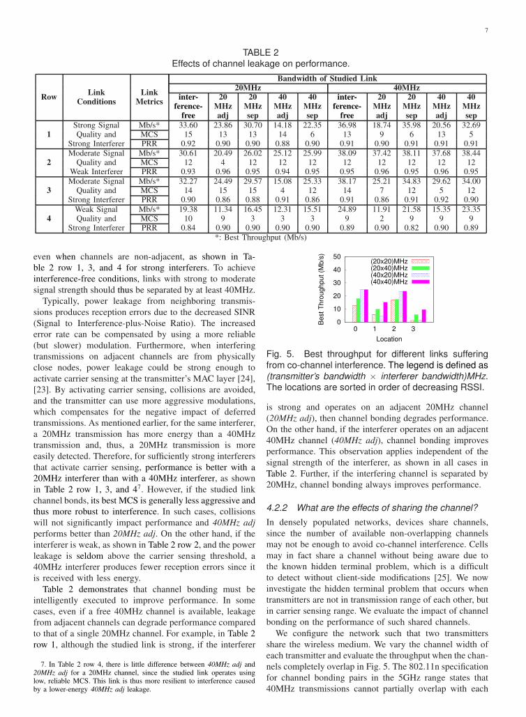
Fig. 5. Best throughput for different links suffering
from co-channel interference. The legend is defined as
(transmitter’s bandwidth × interferer bandwidth)MHz.The locations are sorted in order of decreasing RSSI.
is strong and operates on an adjacent 20MHz channel
(20MHz adj), then channel bonding degrades performance.
On the other hand, if the interferer operates on an adjacent
40MHz channel (40MHz adj), channel bonding improves
performance. This observation applies independent of the
signal strength of the interferer, as shown in all cases in
Table 2. Further, if the interfering channel is separated by
20MHz, channel bonding always improves performance.
4.2.2 What are the effects of sharing the channel?
In densely populated networks, devices share channels,
since the number of available non-overlapping channels
may not be enough to avoid co-channel interference. Cells
may in fact share a channel without being aware due to
the known hidden terminal problem, which is a difficult
to detect without client-side modifications [25]. We now
investigate the hidden terminal problem that occurs when
transmitters are not in transmission range of each other, but
in carrier sensing range. We evaluate the impact of channel
bonding on the performance of such shared channels.
We configure the network such that two transmitters
share the wireless medium. We vary the channel width of
each transmitter and evaluate the throughput when the chan-
nels completely overlap in Fig. 5. The 802.11n specification
for channel bonding pairs in the 5GHz range states that
40MHz transmissions cannot partially overlap with each

8
0
5
10
15
20
25
30
1 2
Best T
hro
ughput (M
b/s
)
Test Case
(20x20)MHz(20x40)MHz(40x20)MHz(40x40)MHz
Fig. 6. Best throughput for a link (location 1 in Fig. 5)
suffering from co-channel interference. In Test Case1, the overlapping transmitter has good link quality to
its receiver and operates at MCS 10. In Test Case 2,
the overlapping transmitter has poor link quality to itsreceiver, and thus operates at MCS 0.
other [7]. For simplicity, we refer to the transmitter under
question as T and the transmitter sharing the channel with T
as S. We define the legend in Fig. 5 as: (T channel-width ×
S channel-width)MHz. We vary the signal strength between
T and its corresponding receiver and order the locations by
decreasing signal quality. S always has good signal quality
to its receiver and operates at high transmission rates.
The best performance in Fig. 5 occurs when both T and
S operate on a 40MHz channel (40×40 MHz). In most
cases, T’s operation on a 40MHz channel, independent of
the bandwidth of S, improves performance compared with a
20MHz channel; however, this condition is not guaranteed
and depends on how effectively a link can take advantage
of signal strength to increase data rate, as discussed in
Section 4.1. For example in Location 1, T’s performance
degrades with channel bonding when it competes for the
medium with a 20MHz interferer (40×20 MHz). In this
case, performance degrades due to the combined effects of
interference and channel sharing, resulting from S being
a weak interferer. When sharing a channel with a weak
interferer, not all transmissions can be detected, and thus
the “effective” noise on the shared channel will increase;
the increased errors in 40MHz forces T to use slower MCS.
In situations where multi-rate CSMA nodes share the
medium, since all transmitters have the same access rights,
low data rate nodes have been found to capture the medium
for longer periods of time, thus penalizing fast stations [26].
Therefore, we also evaluate the scenario where, instead of
operating at high data rates, S operates at low data rates,
shown in Fig. 6. Test cases 1 and 2 correspond to the
scenario in location 1 of Fig. 5; however, in Test case 2,
S now operates at the lowest data rate of MCS 0. As we
can see, when S operates at low rates, T does not improve
performance by channel bonding.
Our findings on channel sharing show that, regardless
of the bandwidth of T, it is more advantageous for T to
compete for the channel with an interferer who transmits
at 40MHz: 40MHz interferers attain higher transmission
rates and alleviate fairness issues in multi-rate scenarios,
leading to better performance. However, the decision to
channel bond relies on the accurate characterization of T’s
potential to take advantage of channel bonding, as described
0
5
10
15
20
25
30
0 1 2 3
Best T
hro
ughput (M
b/s
)
Location
20Mbps, MCS1150Mbps, MCS10
Fig. 7. Best throughput for different links suffering
from a 40MHz co-channel interferer and fairness con-straints. The locations are sorted in order of decreasing
RSSI.
0
20
40
60
80
100
2 10 30 70 150
Best T
hro
ughput (M
b/s
)
Interferer Load (Mb/s)
(20x20)MHz(20x40)MHz(40x20)MHz(40x40)MHz
Fig. 8. Best throughput for a link suffering from co-channel interference with varying interferer load. We
define the legend: (transmitter’s bandwidth × interfererbandwidth)MHz.
in Section 4.1, as well as knowledge of the transmission rate
of S with its corresponding receiver.
4.3 How does channel utilization affect
performance?
In channel sharing conditions, a station’s medium access
opportunities depend on the load imposed on the network
by other interferers operating on the same or overlapping
channels. We now evaluate the impact of different load
levels on the performance of channel bonding.We configure
the network with two transmitters sharing the wireless
medium, and use a configuration identical to the one in
Section 4.2.2. We again refer to the studied transmitter as
T and the transmitter sharing the channel with T as S.
In order to isolate the effect of channel utilization on
performance, we enable packet aggregation in these exper-
iments so that transmitters with a high MCS are allowed a
higher degree of aggregation. This means that fast STAs can
send more aggregated frames per transmission opportunity
than slow STAs, enabling airtime fairness [27]. As we
show in Fig. 7, packet aggregation mitigates the impact
of fairness issues caused in such multi-rate scenarios and
allows us to evaluate the impact of channel utilization
alone. Under the same channel utilization conditions for
the interferer S, S at MCS 1 impacts the performance of T
similarly to when S operates at MCS 10.
We make two key observations as we evaluate the impact
of load on performance in Fig. 8. Our first observation is
that the benefit of channel bonding decreases with increased
load. For the same interferer bandwidth and rate, the benefit
of channel bonding decreases as the load imposed by the

9
TABLE 3Comparison of TCP and UDP performance.
Link LinkUDP TCP
Metric Strength20 40 20 40
MHz MHz MHz MHz
Achieved Strong 29.66 32.35 21.72 24.26Throughput Moderate 22.94 27.46 17.44 21.22(Mbps) Weak 16.50 25.66 12.00 20.22
BestStrong 15 13 13 13
MCSModerate 12 12 12 11Weak 5 11 10 11
ThroughputStrong 9 12
Gain (%)Moderate 20 22Weak 56 69
interferer increases and the link approaches saturation. In
saturation, there is high contention for the shared medium
and little time to exploit the benefits of channel bonding.
Our second observation is that, with increased load,
it is still better for stations to compete for the medium
with a 40MHz interferer, until saturation, at which point
performance differences are minimal. As discussed in Sec-
tion 4.2.2, competing with a 40MHz interferer reduces
fairness issues due to higher PHY rates achieved by channel
bonding. The highest throughput is achieved when both T
and S operate on completely overlapping 40MHz channels
(40x40 MHz).
Our findings reveal that our channel bonding decisions
will differ depending on the channel utilization of the over-
lapping channel. For example, a transmitter might choose
to compete with a 20MHz interferer with low load instead
of a 40MHz interferer with higher load.
4.4 What are the performance benefits of channelbonding using TCP traffic?
We now evaluate the performance of channel bonding under
TCP traffic. TCP is more sensitive to packet losses, and
we therefore evaluate the impact of varying PRR levels on
performance. In Table 3, we show a representative sample
of our performance measurements from 15 different links
using TCP traffic. We compute the achieved throughput
of each link, the corresponding MCS that achieves that
throughput value, which we refer to as the Best MCS,
as well as the channel bonding throughput gain. We also
include UDP results for the same links to compare against.
As expected, we find that for varying link strengths,
and for the same transmission bandwidth, TCP throughput
values are lower than UDP throughput values. This result
is due to TCP’s increased overhead and higher sensitivity
to packet losses. However, if we look at the throughput
gains from channel bonding, we find that the performance
benefits under UDP traffic are also observed under TCP
traffic. Though a 40MHz channel is more susceptible to
loss [5], channel bonding is capable of achieving higher
throughput values for all link strengths. Furthermore, we
observe that the performance improvements achieved by
UDP over TCP are similar for both 20MHz and 40MHz
channels, provided that a more conservative MCS is used
to counteract both the increased errors caused by channel
bonding as well as TCP’s sensitivity to errors. As such,
channel bonding does not appear to particularly affect TCP.
Along the same lines, we also observe that, regardless
of the traffic type, the MCS chosen by a 20MHz channel
is generally more aggressive than that chosen by a 40MHz
channel8. Since a 40MHz channel is more susceptible to
interference, it utilizes more reliable (i.e., low) MCS rates
in order to maximize performance.
Though a 40MHz channel is more susceptible to noise
and interference, and TCP traffic suffers from greater sensi-
tivity to loss, the combination of TCP and channel bonding
still provides performance benefits as compared to a 20MHz
channel. This result demonstrates that the performance
improvements of channel bonding are not restricted to
a particular traffic type. Hence, 40MHz channels can be
exploited in WLANs for both UDP and TCP traffic in order
to achieve higher data rates.
5 IDENTIFYING CHANNEL BONDING
OPPORTUNITIES
Through our investigations in Section 4, we identified
the network characteristics that are either conducive or
detrimental to the performance of channel bonding. With
this knowledge, we now answer some questions that allow
us to evaluate a network to determine channel bonding op-
portunities and to make recommendations of when channel
bonding improves the performance. This information could
be used as valuable input to a channel management scheme.
5.1 How can unfavorable network conditions be
determined from performance metrics?
There are multiple conditions in WLANs that contribute
to performance variations. Of these conditions, some can
be mitigated through intelligent channel management so-
lutions without readjustments to the network topology nor
client-side modifications; we refer to these conditions as
unfavorable network conditions. In our work, we identify
two possible unfavorable conditions. One condition is the
presence of nodes that operate on overlapping channels. The
second condition is interference caused by channel leakage
from nodes operating on adjacent channels. As shown in
previous sections, both conditions lead to degradations in
performance if left unidentified and unresolved.
In the evaluation of our results, we define normalized
throughput, an accurate indicator for unfavorable network
conditions. Based on normalized throughput, we design and
implement a MAC-layer anomaly detector that successfully
alerts to the presence of unfavorable network conditions
in 100% of the test cases. This detector can form the
foundations of future channel management algorithms.
5.1.1 Normalized Throughput
Normalized throughput is the ratio of the achieved through-
put over the expected throughput. Expected throughput
is the throughput that would be achieved in an ideal
8. MCS 8–15 apply the same modulation and coding as MCS 0–7.

10
0
0.2
0.4
0.6
0.8
1
0 1 2 3 4 5 6 7 8 9 10 11 12 13 14 15
Norm
aliz
ed T
hro
ughput
Modulation and Coding Scheme (MCS)
20MHz40MHz
(a) Interference-free environment
0
0.2
0.4
0.6
0.8
1
0 1 2 3 4 5 6 7 8 9 10 11 12 13 14 15
Norm
aliz
ed T
hro
ughput
Modulation and Coding Scheme (MCS)
(20x40)MHz(40x40)MHz(20x20)MHz(40x20)MHz
(b) Channel overlap with another transmission
0
0.2
0.4
0.6
0.8
1
0 1 2 3 4 5 6 7 8 9 10 11 12 13 14 15
Norm
aliz
ed T
hro
ughput
Modulation and Coding Scheme (MCS)
20MHz sep40MHz sep20MHz adj40MHz adj
(c) Channel leakage from a neighboring 20MHz transmission
0
0.2
0.4
0.6
0.8
1
0 1 2 3 4 5 6 7 8 9 10 11 12 13 14 15
Norm
aliz
ed T
hro
ughput
Modulation and Coding Scheme (MCS)
20MHz sep40MHz sep20MHz adj40MHz adj
(d) Channel leakage from a neighboring 40MHz transmission
Fig. 9. Normalized throughput of a moderate strength
link.
environment. We measure achieved throughput at the MAC
layer. Similar to [28], we calculate expected throughput
(ETh) in terms of delay per packet:
ETh =K · Ldata · PRR
DIFS + TBO(PRR) + TKdata + SIFS + TACK
(1)
where K is the number of aggregated frames, which is
equal to 1 with disabled aggregation; Ldata is the payload
carried per frame (in bits); DIFS is the time interval
a wireless medium should be idle before a station can
transmit; TBO is the average backoff time, which is a
function of the PRR; TKdata is the total time required
to send the A-MPDU (including preamble and headers)
at a given PHY rate; SIFS is the constant time interval
between a data frame and its ACK; and TACK is the time
required to send an ACK frame (or Block ACK).
We observe from our results that normalized throughput
is a good indicator of unfavorable network conditions;
the greater the impact an unfavorable condition has on
performance, the more clearly the impact is reflected in
the computed normalized throughput at each MCS.
Fig. 9 depicts the typical behavior of normalized through-
put for all MCS under varying network conditions. Fig. 9(a)
computes normalized throughput for a single link in an
interference-free environment. For that link, Fig. 9(b) rep-
resents values when a second link operates on an over-
lapping channel, while Figs. 9(c) and (d) show values
when a second link operates on a non-overlapping, yet
adjacent, channel. We find that the behavior of a link in
an interference-free environment is consistent, independent
of the strength and conditions of that link. This observation
allows us to identify and characterize situations where
performance is affected by unfavorable network conditions.
We now explain our observation and reasoning.
Fig. 9(a) depicts the behavior we observe in an
interference-free environment. We note a gradual drop
in normalized throughput as transmission rates increase.
For low MCS, particularly for MCS values of 0, 1, 2 and
8, 9, 10, the achieved throughput very closely approximates
the expected throughput with ratios between 90% and
100%. This condition holds as long as the RSSI of the link
in question is greater than the receiver’s minimum input
sensitivity. However, as rates increase, ratios monotoni-
cally drop. Furthermore, we observe that 20MHz channels
achieve higher ratios than 40MHz channels for all MCS.
Therefore, we believe that the distance of the achieved
throughput from the expected throughput is due to the strict
SNR requirements necessary to achieve those rates.
The difference between achieved and expected through-
put increases depending on the severity of the aforemen-
tioned penalty imposed on fast stations due to sharing a
medium with slow stations. Therefore, even with a high
PRR, the achieved throughput will be lower than expected.
If we look at Figs. 9(b), (c), and (d), we notice a consistent
pattern, which is the drop in normalized throughput for low
MCS, which we do not observe in interference-free settings.
This drop is reflected in the higher transmission rates where
normalized throughput drops more steeply.
Next, we test the effectiveness of using normalized
throughput in the design of a MAC-layer anomaly detector.
5.1.2 Network Anomaly Detector
We now discuss our network anomaly detector. We start
by describing how normalized throughput forms the foun-
dations of our detection mechanism, using results shown
in Fig. 10. We plot the CDFs of the PRR and the
corresponding normalized throughput values for multiple
links of varying strength, channel width, and MCS. We
further subject our links to the different network conditions
investigated in this work, namely channel sharing, leakage,
and interference-free conditions. To emulate an intelligent

11
0
0.2
0.4
0.6
0.8
1
0 0.2 0.4 0.6 0.8 1
CD
F
Packet Reception Rate (PRR)
20MHz overlap40MHz overlap
20MHz adj40MHz adj
20MHz sep40MHz sep
interference-free
(a) CDF of packet reception rate (PRR)
0
0.2
0.4
0.6
0.8
1
0 0.2 0.4 0.6 0.8 1
CD
F
Normalized Throughput
20MHz overlap40MHz overlap
20MHz adj40MHz adj
20MHz sep40MHz sep
interference-free
(b) CDF of normalized throughput
Fig. 10. CDF of PRR and the corresponding nor-
malized throughput values for multiple links of varyingstrength, channel width, and MCS.
rate adaptation solution that reacts to changes in PRR [21],
[29], [30], Fig. 10 only includes the results from MCS
values that provide reasonable PRR levels for each link.
As we can see from Fig. 10(a), the PRR achieved
by these links under varying network conditions show
little difference compared to the interference-free scenario.
However, although a successful rate adaptation solution
can maintain an acceptable PRR despite changes in net-
work conditions, the corresponding CDF of normalized
throughput values for the given PRR values depicts con-
siderable differences in behavior, as shown in Fig. 10(b).
In interference-free conditions, around 80% of the links
have normalized throughput values greater than 0.9, and
almost all links have values greater than 0.8. This means
that the achieved throughput closely approximates the ex-
pected throughput in interference-free conditions. However,
in the presence of interference, normalized throughput is
distributed over a wider range of values and, in the best
case, less than 10% of links attain values greater than 0.8.
This increasing difference between achieved and expected
throughput reveals the presence of an interferer.
We use this insight to implement a MAC-layer detector
that monitors changes in normalized throughput. To com-
pute the expected throughput in time, we used the per-
packet transmission and reception statistics from Eq. 1.
The achieved throughput is computed as the total number
of bytes received in a given time, divided by that time.
By averaging the achieved throughput over time, we avoid
rapid reconfigurations due to non-persistent interfering
sources, thus preventing unnecessary and costly channel
migrations. Such highly dynamic interference conditions
can be efficiently handled by a fine-grained per-packet rate
adaptation mechanism [30].
By subjecting our MAC-layer detector to changing net-
work conditions, we find that it successfully identifies
unfavorable network conditions, or anomalies, in the envi-
ronment in 100% of the test cases. With such high success
rates, this detector can form the foundations of future
channel management algorithms.
It is worth noting that monitoring changes in normalized
throughput to detect anomalies is a useful tool in cases
where T is fully saturated. For unsaturated transmitters, the
detector could be adapted to consider other metrics, for
example medium access delay.
5.2 Which parameters characterize a network todetermine opportunities for channel bonding?
We compile a list of parameters that facilitate network char-
acterization. This characterization can be applied in both
centrally managed and distributed network environments.
Signal strength at receiver (RSSI): Our results show that
RSSI is a prerequisite to determining whether 40MHz trans-
mission could improve performance. If RSSI is above the
minimum input sensitivity of a 40MHz channel (depends on
MCS) in an ideal environment with minimum interference,
a 40MHz channel always outperforms a 20MHz channel.
MCS in use: Since the minimum receiver sensitivity
varies according to the MCS in use (higher for faster
modulations), a proper selection of the MCS helps to
maximize the benefits of channel bonding. In other words,
to get the most from channel bonding, it should be set
jointly with rate adaptation.
Strength of interfering transmissions: This metric
is crucial to determine whether to bond. For example,
neighboring links with strong signal strengths to each other
will benefit from operating on non-overlapping channels
separated by at least 20MHz, to avoid interference from
channel leakage.
Physical rates of links in CS range: Beyond the
increased contention, links that operate on the same or on
overlapping channels, are susceptible to fairness issues in
multi-rate scenarios. Knowing the PHY rate of neighboring
links is required not only to make good decisions on when
to channel bond, but also on which channel should be used.
5.3 Can performance on a 40MHz channel be in-
ferred from performance on a 20MHz channel?
Due to multipath diversity in wireless environments, trans-
missions are susceptible to frequency-selective fading.
Frequency-selective fading occurs when signals from dif-
ferent paths combine destructively at the receiver and
the effect of signal-cancellation is deepest only at par-
ticular frequencies. Frequency-selective fading is an un-
predictable factor in network environments and degrades
performance [31]. Wider channels are thus more susceptible
to frequency-selective fading. For the above mentioned rea-
sons, performance from a 20MHz channel cannot be used
to infer performance on a 40MHz channel, and we have
further confirmed this behavior through experimentation.

12
(a) Test Case 1
(b) Test Case 2
(c) Test Case 3
(d) Test Case 4
Fig. 11. Scenarios to demonstrate the impact of in-
telligent channel bonding decisions on network perfor-mance. In each case, a node T requests bandwidth.
The amplitude of signals represents their strength at
T. The bold lines represent our suggested channelconfigurations for T, while the numbered dotted lines
indicate possibilities for naı̈ve channel assignments.
5.4 Should we increase channel width to 40MHzwith incomplete knowledge of the neighboring
20MHz channel?
Based on the data presented so far, the answer is clearly no.
Not only information on the status of the adjacent channel
is required due to channel leakage (cf. Section 4.2.1), but
even interfering transmissions on separate channels could
potentially affect channel management decisions. If channel
bonding is performed under unfavorable conditions, per-
formance will degrade. Particularly, if a 20MHz channel
bonds with a channel that is used by a transmitter in
carrier sensing range, the medium would then be shared by
both transmitters. If the transmitter in carrier sensing range
operates at a low physical rate, then performance suffers
further due to fairness issues in multi-rate scenarios. As
discussed in Section 5.2, there are network parameters that
should be identified to perform an intelligent assignment of
channel widths to improve network throughput.
6 EVALUATION OF INTELLIGENT CHANNEL
BONDING
To demonstrate the impact of intelligent channel bonding
decisions on network performance, we create network
scenarios where naı̈ve uninformed solutions to channel
management lead to incorrect and detrimental decisions.
0
10
20
30
40
50
60
1 2 3 4Ach
ieve
d T
hro
ug
hp
ut
(Mb
/s)
Test Case
BestOption 1Option 2Option 3
Fig. 12. Comparison of T ’s performance using in-
telligent channel bonding decisions versus naı̈ve ap-proaches.
We show that our understanding of channel bonding allows
us to make intelligent decisions that leverage the bene-
fits of channel bonding in typical 802.11n environments.
We present four different test case scenarios, depicted in
Fig. 11. In each test case, we characterize the network en-
vironment and, accordingly, decide on a channel assignment
for a single node T. We then evaluate T’s performance
using our intelligent approach and compare it with T’s
performance from naı̈ve channel management decisions. It
is worth noting that the same logic we apply for a single
node can also be applied in the context of a centrally-
managed network. We restrict our analysis to one link since
our aim is to demonstrate a proof-of-concept.
For each test case scenario, we depict the corresponding
assignment of channels to links in the network, and indi-
cate the possible assignments for T using our intelligent
approach (in bold) and a possible set of naı̈ve alternatives
(dashed). The strength of the active links with respect
to T is represented by the amplitude of the signal. All
transmitters are driven to saturation to gauge the capacity
of each link. We limit the number of available channels to
recreate contention for bandwidth in a large-scale testbed.
In all links, RSSI is above the minimum receiver sensitivity
(cf. Section 4.1.1). Furthermore, in these experiments, we
enable frame aggregation and automatic rate selection to
replicate the behavior of typical off-the-shelf devices. The
performance results from each possible channel selection
for T, for each test case, are shown in Fig. 12.
Case 1, Fig. 11(a): All available channels are occupied.
To minimize interference, a naı̈ve approach would scan the
available channels and assign T the channel on which the
weakest interfering signal is received. In this case, T can
be assigned a single 20MHz channel at either channels
44 or 56: Option 1 or Option 3, respectively. T could
also be assigned bonded channels 52 and 56: Option 2.
On the other hand, our intelligent solution identifies an
opportunity to maximize performance by channel bonding
on channels 36 and 40, where the existing transmitter also
operates with a 40MHz channel: Best. Intelligent channel
bonding will eliminate Option 2 because the strong adjacent
20MHz transmission at channel 48 will cause interference
from channel leakage. Option 1 is disregarded for the same
reason. As for Option 3, we do not distinguish any added
benefit over Best; knowledge of the MCS used by the

13
interfering transmitters would be a key factor for deciding
between both options (cf. Section 4.2.2). As shown in
Fig. 12, our intelligent solution maximizes performance
considerably, with up to 7 factor increase in achieved
throughput compared to the naı̈ve solutions.
Case 2, Fig. 11(b): Two channels are free. A naı̈ve
decision would assign T the free 40MHz channel: Option
1. However, our study indicates that interference from
channel leakage from the neighboring 20MHz transmitter
on channel 44, which has a strong signal strength to T,
can degrade performance. Therefore, our intelligent channel
bonding solution assigns channel 36 to T: Best. As shown
in Fig. 12, our intelligent solution improves performance
by a factor of 83%, from 18Mb/s to 33Mb/s.
Case 3, Fig. 11(c): Only one unoccupied 20MHz channel.
Similar to Case 2, a naı̈ve approach would assign the free
20MHz channel 48 to T: Option 1. In this case as well,
performance can degrade due to interference from channel
leakage from the two neighboring 20MHz transmissions,
on channels 44 and 52, with strong signal strength to T.
The alternative identified by our intelligent approach is
to transmit on a 40MHz-width channel, on channels 36
and 40, in parallel with an existing 40MHz transmission
operating at a high physical rate: Best. As shown in Fig. 12,
by identifying the opportunity for channel bonding, we
increase the performance by 38%, from 13Mb/s to 18Mb/s.
Case 4, Fig. 11(d): We now evaluate the impact of channel
utilization. This test case scenario is identical to the one
used in Case 1, except we now vary the channel utilization
of each interferer. A naı̈ve approach would ignore the
impact of channel utilization; thus, its assignment decisions
would not differ from those in Test Case 1. In this test
case, the interferer on channels 36 and 40 operates at 80%
channel utilization, the interferer on channel 44 at 60%, on
channel 48 at 50%, and on channel 52 and 56 at 80%.
The decision we made in Case 1, which is operation
on channels 36 and 40, no longer achieves the best perfor-
mance, as shown in Fig. 12. T now competes for about 20%
of the channel with a 40MHz interferer with low MCS,
which starves T. Similarly, T in Option 3 competes for
around 50% of the channel with a 20MHz interferer, which
we have shown creates fairness issues. We also evaluate
Option 2, where T operates on a 40MHz channel and
contends for the medium with two unsynchronized 20MHz
interferers; in such cases, it has been shown that the 40MHz
channel will starve [32]. Our intelligent solution identifies
an opportunity to maximize throughput by competing with
the transmitter on channels 52 and 56, which operates at
average MCS with high load: Best. As shown in Fig. 12, we
provide up to a 6 fold increase in throughput by also con-
sidering the impact of channel utilization on performance.
7 CONCLUSION
Channel bonding in 802.11n networks promises increased
data rates and improved performance. In this work, we
identify a key set of network factors that allow us to
accurately assess the impact of network conditions and
channel bonding choices on performance, specifically under
5GHz operation. We find that intelligent channel bonding
decisions rely on the knowledge of a transmitter’s surround-
ings, particularly the signal strength of links, interference
patterns, and channel utilization. Such findings serve as
usage-terms for intelligently incorporating 40MHz opera-
tion in network deployments to maximize performance and
efficiency. We further analyze the behavior of channel bond-
ing under TCP traffic loads, and find that the performance
values are diminished compared to performance under
UDP. However the benefits of wider bandwidths still hold.
Our work serves as a solid foundation on which channel
management solutions for 802.11n networks can be built,
calling on channel management design principles from
existing literature [5], [19]. Our findings can be applied
both at a network scale to improve channel management of
the whole WLAN, and also at a link scale to aid per-packet
rate adaptation mechanisms aimed at optimizing individual
transmitter and receiver pairs [30]. We believe our work will
also apply to the upcoming 802.11ac standard that allows
up to 160MHz bonding channels in the 5GHz band.
8 ACKNOWLEDGMENTS
This work is partially supported by the National Science
Foundation under Grant No. 1032981. Any opinions, find-
ings, and conclusions or recommendations expressed in this
material are those of the author(s) and do not necessarily
reflect the views of the National Science Foundation. This
work is also partially supported by the Spanish Government
through project TEC2009-11453 and Programa Nacional de
Movilidad de Recursos Humanos del Plan Nacional de I-
D+i 2008-2011.
REFERENCES
[1] R. Chandra, R. Mahajan, T. Moscibroda, R. Raghavendra, andP. Bahl, “A case for adapting channel width in wireless networks,”in ACM SigComm, August 2008.
[2] K. Pelechrinis, I. Broustis, T. Salonidis, S. V. Krishnamurthy, andP. Mohapatra, “Design and deployment considerations for highperformance MIMO testbeds,” in WICON, November 2008.
[3] E. Gelal, K. Pelechrinis, I. Broustis, S. Krishnamurhty, S. Mo-hammed, A. Chockalingam, and S. Kasera, “On the impact of MIMOdiversity on higher layer performance,” in IEEE ICDCS, June 2010.
[4] D. Halperin, W. Hu, A. Sheth, and D. Wetherall, “802.11 withmultiple antennas for dummies,” ACM SigComm Computer Com-
munications Review, vol. 40, pp. 19–25, January 2010.[5] M. Y. Arslan, K. Pelechrinis, I. Broustis, S. V. Krishnamurthy,
S. Addepalli, and K. Papagiannaki, “Auto-configuration of 802.11nWLANs,” in ACM CoNext, November 2010.
[6] K. Pelechrinis, T. Salonidis, H. Lundgren, and N. Vaidya, “Exper-imental characterization of 802.11n link quality at high rates,” inACM WiNTECH, September 2010.
[7] “IEEE 802.11n-2009 Amendment 5: Enhancements for HigherThroughput,” IEEE-SA, October 2009.
[8] V. Shrivastava, S. Rayanchu, J. Yoonj, and S. Banerjee, “802.11nunder the microscope,” in ACM IMC, October 2008.
[9] U. Paul, R. Crepaldi, J. Lee, S.-J. Lee, and R. Etkin, “CharacterizingWiFi link performance in open door networks,” in SECON, June2011.
[10] Texas Instruments, “WLAN channel bond-ing: Causing greater problems than it solves,”http://focus.ti.com/pdfs/bcg/channel bonding wp.pdf, Tech. Rep.,September 2003.

14
[11] L. Deek, E. Garcia-Villegas, E. Belding, S.-J. Lee, and K. Almeroth,“The impact of channel bonding on 802.11n network management,”in ACM CoNEXT, 2011.
[12] D. Tse and P. Viswanath, Fundamentals of Wireless Communication.Cambridge University Press, 2005.
[13] A. Goldsmith, Wireless Communications. Cambridge UniversityPress, 2005.
[14] C. Oestges and B. Clerckx, MIMO Wireless Communications: From
Real-World Propagation to Space-Time Code Design. AcademicPress, 2007.
[15] I. Pefkianakis, Y. Hu, S. H. Wong, H. Yang, and S. Lu, “MIMOrate adaptation in 802.11n wireless networks,” in ACM MobiCom,September 2010.
[16] S. Lakshmanan, S. Sanadhya, and R. Sivakumar, “On link rateadaptation in 802.11n WLANs,” in IEEE Infocom mini-conference,April 2011.
[17] R. Gummadi and H. Balakrishnan, “Wireless networks should spreadspectrum based on demands,” in ACM Hotnets, October 2008.
[18] H. Rahul, F. Edalat, D. Katabi, and C. G. Sodini, “Frequency-awarerate adaptation and MAC protocols,” in ACM MobiCom, September2009.
[19] T. Moscibroda, R. Ch, Y. Wu, S. Sengupta, P. Bahl, and Y. Yuan,“Load-aware spectrum distribution in wireless LANs,” in IEEE
ICNP, October 2008.[20] V. Visoottiviseth, T. Piroonsith, and S. Siwamogsatham, “An empir-
ical study on achievable throughputs of IEEE 802.11n devices,” inIEEE WiOPT, June 2009.
[21] Ath9k wireless driver.“http://linuxwireless.org/en/users/Drivers/ath9k.”.[22] A. Mishra, V. Shrivastava, S. Banerjee, and W. Arbaugh, “Partially
overlapped channels not considered harmful,” in ACM SIGMETRICS,June 2006.
[23] S. Lakshmanan, J. Lee, R. Etkin, S.-J. Lee, and R. Sivakumar, “Re-alizing high performance multi-radio 802.11n wireless networks,” inIEEE SECON, June 2011.
[24] I. Broustis, K. Papagiannaki, S. Krishnamurthy, M. Faloutsos,and V. Mhatre, “MDG: Measurement-driven guidelines for 802.11WLAN design,” in ACM MobiCom, June 2007.
[25] A. Mishra, V. Brik, S. Banerjee, A. Srinivasan, and W. Arbaugh, “Aclient-driven approach for channel management in wireless LANs,”in IEEE Infocom, April 2006.
[26] M. Heusse, F. Rousseau, G. Berger-Sabbatel, and A. Duda, “Perfor-mance anomaly of 802.11b,” in IEEE Infocom, April 2003.
[27] T. Joshi, A. Mukherjee, Y. Yoo, and D. Agrawal, “Airtime fairnessfor IEEE 802.11 multirate networks,” IEEE Transactions on Mobile
Computing, vol. 7, no. 4, pp. 513–527, April 2008.[28] B. Ginzburg and A. Kesselman, “Performance analysis of A-MPDU
and A-MSDU aggregation in IEEE 802.11n,” in IEEE Sarnoff
Symposium, May 2007.[29] Minstrel HT Linux Wireless, ”http://linuxwireless.org/en/developers”.[30] L. Deek, E. Garcia-Villegas, E. Belding, S.-J. Lee, and K. Almeroth,
“Joint rate and channel width adaptation in 802.11 MIMO wirelessnetworks,” in IEEE Secon, June 2013.
[31] D. Halperin, W. Hu, A. Sheth, and D. Wetherall, “Predictable802.11 packet delivery from wireless channel measurements,” inACM SigComm, August 2010.
[32] S. Pollin and A. Bahai, “Performance analysis of double-channel802.11n contending with single-channel 802.11,” in IEEE Interna-
tional Conference on Communications (ICC), June 2009.
Lara Deek received a BE in Computerand Communications Engineering from theAmerican University of Beirut, Lebanon. Sheis currently working towards a PhD degreeunder the guidance of Professors ElizabethBelding and Kevin Almeroth in the Depart-ment of Computer Science at the Universityof California, Santa Barbara. Her research isfocused on designing resource-efficient wire-less systems for emerging wireless networks.She is broadly interested in wireless network
deployment, measurement, protocol design, and implementation.She is a student member of the IEEE.
Eduard Garcia-Villegas received his MScand PhD from the Universitat Politcnica deCatalunya BarcelonaTech (UPC) in 2003and 2010, respectively. He is an assistantprofessor at the same university and a mem-ber of the Wireless Networks Group (WNG).He participates in the research developedwithin the i2CAT Foundation and occasion-ally collaborates with the MOMENT Lab atUC Santa Barbara. His research interestsinclude IEEE 802.11 WLANs, radio resource
management in wireless networks, cognitive radios, wireless meshnetworks, and future Internet architectures.
Elizabeth Belding is a Professor in the De-partment of Computer Science at the Uni-versity of California, Santa Barbara, and iscurrently the departments Vice Chair. Eliza-beths research focuses on mobile network-ing, specifically multimedia, monitoring, ad-vanced service support, and solutions for de-veloping and underdeveloped regions. She isthe founder and director of the Mobility Man-agement and Networking (MOMENT) Labo-ratory. Elizabeth is the author of over 100
technical papers and has served on over 60 program committees fornetworking conferences. She is currently on the steering committeeof the ACM Networked Systems in Developing Regions (NSDR)Workshop and the editorial board of the IEEE Pervasive Magazine.Elizabeth is the recipient of an NSF CAREER Award, and a 2002MIT Technology Review 100 award, awarded to the worlds top younginvestigators. She is an ACM Distinguished Scientist.
Sung-Ju Lee is a Principal Member of Tech-nical Staff at the office of the CTO of Narus,Inc. Before joining Narus, he was a PrincipalResearch Scientist and Distinguished Mo-bility Architect at the Hewlett-Packard Com-pany. He received his PhD in Computer Sci-ence from University of California, Los Ange-les (UCLA) in 2000. Dr. Lee has publishednearly 100 technical papers in peer-reviewedjournals and conferences. His papers arewell-cited, with his publications receiving a
total of nearly 9,000 citations. He currently holds 17 US patents and40-plus pending patents. He won the HP CEO Innovation Award in2010. He is a co-founder and steering committee member of IEEESECON. He is an IEEE Fellow and an ACM Distinguished Scientist.
Kevin Almeroth is currently a Professorin the Department of Computer Science atthe University of California in Santa Barbarawhere his main research interests includecomputer networks and protocols, wirelessnetworking, multicast communication, large-scale multimedia systems, and mobile appli-cations. At UCSB, Dr. Almeroth is the formerfounding Associate Director of the Center forInformation Technology and Society (CITS),a founding faculty member of the Media Arts
and Technology (MAT) Program, Technology Management Program(TMP), and the Computer Engineering (CE) Program. In the re-search community, Dr. Almeroth has authored nearly 200 refereedpapers and is heavily engaged in stewardship activities for a varietyof research outlets including journal editorial boards, conferencesteering committees, new workshops, and the IETF. He is a Memberof the ACM and a Senior Member of the IEEE.