![CENTRAL INTELLIGENCE BULL[15561285] INTELLIGEN… · Iran - Saudi Arabia: Relations damaged by Iran's gunboat diplomacy. ... ports of an imminent rocket attack. ... three-party coalition](https://static.fdocuments.us/doc/165x107/5fcafe810df05559043519cd/central-intelligence-bull15561285-intelligen-iran-saudi-arabia-relations.jpg)
Intelligen Technical
59
INTELLIGEN ® TECHNICAL MANUAL i-325/425/425T
Transcript of Intelligen Technical

INTELLIGEN®
TECHNICAL MANUALi-325/425/425T

INTELLIGEN® TECHNICAL MANUAL 2
Preface 3
Warranty 3
Presentation 3
Notation 3
Applicability 4
Safety 4
Environment 4
Radiation Warning 4
Chapter 1: Specifications 5
Ratings 5
Configuration 6
Operator’s Console 6
Modes of Operation 9
Manual Mode 9
APR Mode 9
VET APR Operator’s Console 11
HV Tank 14
Chapter 2: Installation 15
Site Preparation 15
Unpacking 15
Inspection 15
Mechanical Installation 16
Interconnection 16
P1/P2 Cable 16
Interconnecting Cable 17
Hand Switch 17
Chapter 3: Interface 18
Mains 18
Single Phase, 208 VAC ( i-325/425) 18
3 Phase, 208 VAC 18
3 Phase, 380 VAC 19
Buckys 19
V-RAD SYSTEM BUCKY CONNECTIONS 19
SIMPLIFIED BUCKY CONNECTIONS 21
Rotor 23
External Handswitch/Footswitch 23
Interlocks 24
AEC 25
Auxillary Relay 25
24 VAC Collimator Lamp Power 26
External Exposure Indication 26
Vet Footswitch for “One Touch” Operation 27
Chapter 4: Setup 28
Overview 28
Power On Test 28
Blue Watch Dog LED 28
Power On 28
Pre-Set #s 29
X-Ray Tube Selection 32
mA Station Selection 34
Filament Standby Number 34
HV Cable Length 35
Buckys and AEC Selection 36
Maximum kVp 36
Rotor Speed 36
Low Speed Boost Time 37
Interlock Selection 37
Chapter 5: Calibration 38
kVp Feedback Test 38
Calibration 39
Manual Calibration 42
AUTOCAL 42
AEC Density Adjust 43
Chapter 6: Compliance Testing 44
Overview 44
Configuration 44
Operator’s Console 44
Standard Operator’s Console 45
APR Operator’s Console 48
Exposure Factor Tests 50
kVp/mA 51
Time 52
Reporting 53
Chapter 7: Diagnostics 54
Overview 54
Error Codes 55
Trouble-Shooting Tips 58
Parts List 59
Table of Contents
Copyright 2007 by GTRLABS, Inc.All rights reserved. Contents of this publication may not be reproduced in any form or by any means, electronic or mechanical, including photocopying and recording, or by any information storage or retrieval system without the writ-ten permission of:
GTRLABS, Inc. 510 Elk Street
Gassaway, WV 26624 Telephone: 304-364-2211
web: www.gtrllc.com email: [email protected]

3INTELLIGEN® TECHNICAL MANUAL
Copyright 2010 GTRLABS, Inc.
WarrantyGTR® LABS, Inc. warrants that this product will be free from defects in materials and workmanship for a period of five (5) years from the date of installation at the first end user’s site; If any such product proves defective during this warranty period, GTR®, at it’s option, either will repair the defective product without charge for parts or shop labor, or will provide a replacement in exchange for the defective product.
This warranty shall apply to all equipment and systems sold by GTR® with the exception of the following:X-Ray TubesImage IntensifiersTV Camera TubesThe above items are subject to the manufacturer’s warranty in effect as of the date sold. These warranties vary and are pro-rated. The manufacturer will be the final authority for any warranty claim.
In order to obtain service under this warranty, Customer must notify GTR® of the defect before the expiration of the warranty period and make suitable arrangements for the performance of service. Customer shall be responsible for packaging and shipping the defective product to the service center designated by GTR® with shipping charges prepaid. GTR® shall pay for the return of the product to Customer if the shipment is to a location within the country in which the GTR® designated service center is located. Customer shall be responsible for paying all shipping charges, duties, taxes, and any other charges for products returned to any other locations.
This warranty shall not apply to any defect, failure, or damage caused by improper or inadequate maintenance and care. GTR® shall not be obligated to furnish service under this warranty 1) to repair damage resulting from attempts by personnel other than GTR® representatives to install, repair, or service this product; 2) to repair damage resulting from improper use or connection to incompatible equipment or power source; or 3) to service a product that has been modified or integrated with other products when the effect of such modification or integration increases the time or difficulty of servicing the product.
Further, GTR® LABS, Inc. warrants that the product is in compliance with U.S.A. DHHS regulations which may be in force and effect at the time of shipment of the product.
The following is not covered by the warranty: General maintenance and simple adjustments mentioned in the manuals delivered with the material.THIS WARRANTY IS GIVEN BY GTR® WITH RESPECT TO THIS PRODUCT IN LIEU OF ANY OTHER WARRANTIES, EXPRESS OR IMPLIED. GTR® AND IT’S VENDORS DISCLAIM ANY IMPLIED WARRANTIES OF MERCHANTABILITY OR FITNESS FOR A PARTICULAR PURPOSE. GTR®‘S RESPONSIBILITY TO REPAIR OR REPLACE DEFECTIVE PRODUCTS IS THE SOLE REM-EDY PROVIDED TO THE CUSTOMER FOR BREACH OF THIS WARRANTY. GTR® AND IT’S VENDORS WILL NOT BE LIABLE FOR ANY INDIRECT, SPECIAL, INCIDENTAL, OR CONSEQUENTIAL DAMAGES IRRESPECTIVE OF WHETHER GTR® OR THE VENDOR HAS ADVANCE NOTICE OF THE POSSIBILITY OF SUCH DAMAGES.
There are no warranties which extend beyond the description mentioned in this document.
PresentationThis manual contains information on the installation of the INTELLIGEN® generators.
Notation
NOTE: This is an example of a NOTE. NOTES are areas that need additional attention.
CAUTION: This is an example of a CAUTION. CAUTIONS are procedures that the operator must heed in order to avoid damage to the equipment.
WARNING: This is an example of a WARNING. WARNINGS are procedures that the operator must heed in order to avoid bodily harm or injury.
Preface

INTELLIGEN® TECHNICAL MANUAL 4
Copyright 2010 GTRLABS, Inc.
ApplicabilityThis manual is applicable to the “i” Series, Single Tube RAD generators. i-325 20 kW i-425 30 kW i-425T 30 kW
This manual is shipped with generator Model # __________, Serial #__________, with Software Version _______.
SafetyMechanical-Electrical Warning
All of the electronic assemblies and parts of this equipment should be operated with care and routinely inspected in accordance with the manufacturer’s recommendations.
Only properly trained and qualified personnel should be permitted access to any internal parts. Live electrical terminals are LETHAL. Be sure line disconnect switches are opened and other appropriate precautions are taken before removing covers or attaching accessories.
Do not remove the flexible high tension cables from the x-ray tube housing or high tension generator, and/or the access covers from the generator until the main and auxiliary power supplies have been disconnected.
WARNING: Failure to comply with the foregoing safeguards may result in serious or fatal bodily injuries to the operator or those in the area.
WARNING: This product is not to be used in the presence of flammable anesthetics.
Electrical Grounding Instructions
WARNING: The equipment must be grounded to an earth ground by a separate #8 conductor. The neutral side of the line is not to be considered the earth ground.
NOTE: This is “Type B” Equipment which employs both insulation protection and protective earthing to reduce the risk of electric shock to product users.
EnvironmentStorage and Transportation conditions:Ambient Temperature Range: -40C to +65CRelative Humidity Range: 20 to 80% (non condensing)Atmospheric Pressure Range: -15 meters to 10000 metersOperation Conditions:
This equipment is designed to work within a temperature range of 200C to 300C, with a relative humidity (non-condens-ing) less than 60%. Atmospheric Pressure Range: -15 meters to 3000 meters.
CAUTION: Provide adequate filtration if the generator is installed in a high dust or particulate matter environment.
Radiation Warning
WARNING: X-rays are dangerous to operator unless established safe exposure procedures are observed.

5INTELLIGEN® TECHNICAL MANUAL
Copyright 2010 GTRLABS, Inc.
Table 1-1 Technique Ranges
Chapter 1: Specifications Ratings
CAUTION: For proper operation on a Single Phase or Three Phase Line, it is recommended that you have 220 VAC, -5%/+10% 50/60Hz.
pVk)pVk1fospetsnI( 524/523-i521ot04
Am Am003ot52523-iAm004ot52524-i
emiT sdnoces6otsm2
Technique Factors for maximum line current:Radiographic:
20 kW = 100 kVp @ 200 mA > 20 ms
30 kW = 100 kVp @ 300 mA > 20 ms
The radiographic duty cycle can be one average exsposure every 30 seconds. Mor specifically 300 mAs per minute ie. one 150 mAs every 30 seconds or 600 mAs every two minutes.
Methodology used to measure actual technique factors:
The kVp and mA is measured as the aveage of the top of the waveform.
The exposure time is measured from 75% of rise and fall of the kVp waveform.
Table 1-1A Maximum Technique Selections
Voltage Requirements: 220 VAC (-5%/+10%)Circuit Breaker Size: 100 AmpsWire Type: Stranded Copper Wire Size: #2 Wire (6.54mm diam) for runs less than 50 feet #0 Wire (8.25mm diam) for runs more than 50 feetPower Line Impdeance: 0.30 Ohms or less

INTELLIGEN® TECHNICAL MANUAL 6
Copyright 2010 GTRLABS, Inc.
ConfigurationOperator’s Console
There are 3 Operator’s Consoles that are available with the INTELLIGEN® family of generators.
They are:
Standard Operator’s Console (Part Number 6065.00)
APR Operator’s Console (Part Number 6072.00)
VET APR Operator’s Console (Part Number 6103)
Refer to the illustrations below to determine the Operator’s Console with your system.
Standard Operator’s Console(Part Number 6065.00)
APR Operator’s Console (Part Number 6072.00)
VET APR Operator’s Console(Part Number 6103)

7INTELLIGEN® TECHNICAL MANUAL
Copyright 2010 GTRLABS, Inc.
NOTE: Throughout the Technical Manual references are made to various aspects of the Operator’s Console. These include the reconfiguration of displays during Setup (Chapter 4), Calibration (Chapter 5) and Compliance (Chapter6). Familiarize yourself with the specific Operator’s Console supplied with your system and take note of it’s characteristics.
20
1. kVp Display 2. mA Display 3. Time Display 4. mAs Display 5. kVp Up/Down 6. mA Up/Down 7. Time Up/Down 8. mAs Up/Down 9. AEC Density Up/Down10. BKY Select11. EXP12. PREP
13. AEC Field Select14. AEC Reset15. Overload LED16. Collimator LED17. Interlock LED18. On/Off19. Hand Switch20. Connector
1 2 3 4
5 6 7 8
9
10
111213141516
Figure 1-1A Standard Operator’s Console (Front View)
Figure 1-1B Standard Operator’s Console (Rear View)
18 17
19
INTELLIGEN® TECHNICAL MANUAL 8
Copyright 2010 GTRLABS, Inc.
20
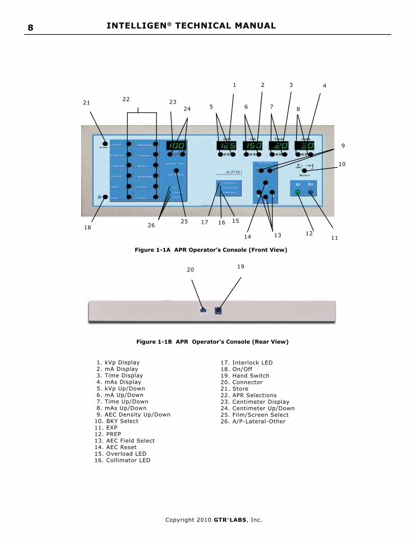
1. kVp Display 2. mA Display 3. Time Display 4. mAs Display 5. kVp Up/Down 6. mA Up/Down 7. Time Up/Down 8. mAs Up/Down 9. AEC Density Up/Down10. BKY Select11. EXP12. PREP13. AEC Field Select14. AEC Reset15. Overload LED16. Collimator LED
17. Interlock LED18. On/Off19. Hand Switch20. Connector21. Store22. APR Selections23. Centimeter Display24. Centimeter Up/Down25. Film/Screen Select26. A/P-Lateral-Other
1 2 3 4
5 6 7 8
9
10
11121314
1516
Figure 1-1A APR Operator’s Console (Front View)
Figure 1-1B APR Operator’s Console (Rear View)
1817
19
21 22 2324
2526

9INTELLIGEN® TECHNICAL MANUAL
Copyright 2010 GTRLABS, Inc.
Modes of OperationThe APR Operator’s Console has three (3) modes of operation:
Manual ModeAPR ModeAEC Mode
Each mode has it’s own, specific characteristics of operation. Please read each description carefully to note the dif-ferences and similarities.
Manual ModeIn the Manual Mode of operation the APR Operator’s Console acts just like the Standard Console supplied with the VALUEGEN® generators. You may manually input values for kVp, mA, Time and mAs as well as select a Bucky (if the option is installed). Exposures are based on this manually entered technique.
APR functions are not available while in the Manual Mode.
The Manual Mode is indicated when the Centimeter Display is not illuminated and there are no AEC selections made (if the option is installed).
APR ModeThe APR Mode is indicated by having the Centimeter Display illuminated and one of the green APR Selection LEDs lit. In the APR Mode the operator may make an APR Selection of anatomy region and view and select a Centimeter Thick-ness. This will automatically select and display a technique based upon the Technique Chart stored in memory.
NOTE: In the APR Mode, with the Centimeter Display illuminated, pressing any pushbutton on the right side of the console will automatically put the console in the Manual Mode.
Change Individual TechniquesTo change any of the individual techniques stored in any of the APR Selection locations, use the following procedure:
Press and hold the STORE pushbutton (21) on the APR Operator’s Console. While holding this pushbutton, select the anatomy region (ie. Chest), the view (ie. AP), the Centimeter Thickness (23), kVp, mA, Time, mAs and any optional equipment installed (ie. Bucky 1, AEC Field 2).
Release the STORE pushbutton and observe that the decimal point in the Centimeter Display illuminates momentarily to indicate storage of the technique.
This technique is now permanently stored in the selection you have made.
NOTE: Storing a specific technique in this manner does not affect any of the other techniques stored in the APR Operator’s Console.
Change Stored Techniques GloballyVersion 2.0 of the Human Anatomical Console (APR) software adds the capability to automatically change the stored technique factors for increased or decreased film density. Incremental changes of approximately 0.3 optical density (OD) can be made by console pushbutton combinations. All stored technique factors can be changed at once or all thicknesses for one view can be changed at once. A change of approximately 0.9 OD is equivalent to doubling (halv-ing) the film speed. Therefore increasing all technique factors by 0.3 three times is equivalent to changing from 400 speed to 200 speed film.
There are two ways to globally change the techniques stored in the APR Console Memory.
1. Change all technique factors stored in memory
2. Change all technique factors for a specific selected anatomical region.Change All Technique Factors Stored In Memory
Make sure there is no APR view selected (no indication in CM Display).
Press STORE and AEC Density UP Pushbuttons simultaneously (the decimal point in the CM display will illuminate to indicate activity) This function increases all stored technique factors by approximately 0.3 OD.
OR
Press STORE and AEC Density DOWN Pushbuttons simultaneously (the decimal point in the CM display will illuminate to indicate activity). This function decreases all stored technique factors by approximately 0.3 OD.

INTELLIGEN® TECHNICAL MANUAL 10
Copyright 2010 GTRLABS, Inc.
Technique TransferVersion 2.0 and higher of the Human APR Console allows for the internal transfer of technique factors to an EEPROM for storage and recall. If you customize your APR Technique settings you can save them for recall on the EEPROM.
NOTE: You must be in the Service Mode to perform operations with the EEPROM.
Wth the generator in the Service Mode press simultaneously the STORE and CM UP pushbuttons. This will store the techniques you have programmed into the console on the EEPROM. The decimal point in the CM Display will illuminate during transfer.
With the generator in the Service Mode press simultaneously the STORE and CM DOWN pushbuttons. This will transfer the techniques stored in the EEPROM back into the console. The decimal point in the CM Display will illuminate during transfer.
If you experience a console failure and have to replace the console and you have previously stored the altered techniques in the EEPROM you may take the EEPROM out of the failed console and install it in the new console and exectue a STORE/CM DOWN function in the service mode to restore your techniques in the new console.,
AEC ModeThe AEC Mode is applicable if the generator has the AEC Option installed.
The AEC Mode is used in conjunction with the Manual Mode or the APR Mode.
The AEC Mode is indicated by one or more of the FIELD LEDs (13) being illuminated.
Change All Technique Factors For An Anatomical RegionSelect a specific APR view (ie. Chest AP or Skull LAT etc.).
Press STORE and AEC Density UP Pushbuttons simultaneously (the decimal point in the CM display will illuminate to indicate activity). This function increases all stored techniques for each CM station of the selected APR View by ap-proximately 0.3 OD. No other factors are changed.
OR
Press STORE and AEC Density DOWN Pushbuttons simultaneously (the decimal point in the CM display will illuminate to indicate activity). This function decreases all stored techniqeus for each CM station of the selected APR View by approximately 0.3 OD. No other factors are changed.
NOTE: During any of the above procedures, the decimal point in the CM Display will illuminate to indicate activity. This may take up to 30 seconds. During the time the decimal point is illuminated, no other operation is allowed.
NOTE: Pressing STORE and AEC RESET Pushbuttons simultaneously will reset all APR stored techniques to factory default.
NOTE: The Human APR Console must be set to the corresponding Model of the Generator for these new functions to work properly.
Set Model NumberFor the Version 2.0 software changes of the Human APR Console to work properly you must set the Model Number of the generator as well. With the generator in the Service Mode the following displays will indicate the different model numbers. Pressing the corresponding pushbutton sets the console for the correct Model Number.Chest 10kW C-Spine 20kW i-325L-Spine 30kW i-425Pelvis 40kW Arm 50kW

11INTELLIGEN® TECHNICAL MANUAL
Copyright 2010 GTRLABS, Inc.
AEC Mode with Manual Mode:
The Operator must select a Backup Time of sufficient lenght to exceed the expected exposure time using AEC. It is suggested that this Backup Time be at least 2 times the expected exposure time.
AEC Mode with APR Mode:
None of the APR Selections contain AEC from the factory even if the AEC option is installed. All of the stored techniques are based upon the Technique Chart in Appendix 1 of this manual.
If the operator wishes to add AEC functions to the stored techniques you must follow the instructions for STORE in the above section on APR Mode.
When adding AEC to one or more of the stored APR Selections remember to select an appropriate Backup Time for each selection.
CAUTION: Failure to program in a Backup Time for each APR Selection you add an AEC funcion to will result in the Backup Time warning LED being illuminated and require an AEC Reset.
Figure 1-3A VET APR Operator’s Console (Front View)
Figure 1-3B VET APR Operator’s Console (Rear View)
1 2 3 4
5 6 7 8
9
10
11121314
151618
17
21 22 2324
2526
20
1. kVp Display 2. mA Display 3. Time Display 4. mAs Display 5. kVp Up/Down 6. mA Up/Down 7. Time Up/Down 8. mAs Up/Down 9. AEC Density Up/
Down10. BKY Select11. EXP12. PREP13. AEC Field Select14. AEC Reset15. Overload LED16. Collimator LED17. Interlock LED
19
18. On/Off19. Hand Switch20. Connector21. Store22. APR Selections23. Centimeter Display24. Centimeter Up/Down25. Film/Screen Select26. A/P-Lateral-Other

INTELLIGEN® TECHNICAL MANUAL 12
Copyright 2010 GTRLABS, Inc.
Figure 1-4 Cabinet (Front View)
HV Tank
GCU
Figure 1-5 Chassis (Front View)
Bridge Rectifier
Charge Relay
Flux Capacitor
Rotor Capacitor
IPM #1
IPM #2
Line Fuses
SPB pcbTEC pcb
CVI pcb
Figure 1-6 Chassis (Right Side)
TEC pcb SPB pcb
Figure 1-7 Chassis (Left Side)
BBU pcbDischarge Resistor
Charge Resistor
13INTELLIGEN® TECHNICAL MANUAL
Copyright 2010 GTRLABS, Inc.
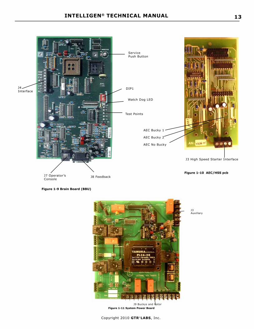
Figure 1-9 Brain Board (BBU)
J8 FeedbackJ7 Operator’s Console
DIP1 J4 Interface
Service Push Button
Watch Dog LED
Test Points
Figure 1-10 AEC/HSS pcb
J3 High Speed Starter Interface
AEC Bucky 1
AEC Bucky 2
AEC No Bucky
Figure 1-11 System Power Board J9 Buckys and Rotor
J3 Auxillary

INTELLIGEN® TECHNICAL MANUAL 14
Copyright 2010 GTRLABS, Inc.
1 amp fuse
Figure 1-12 TEC (Thermionic Emission Controller)
Status LEDs
Filament Interface to HVT
Ribbon to BBU
240 VAC
Figure 1-13 IPM Driver
IPM connectors
Ribbon connector (to BBU)
HV Tank
Figure 1-14 HV Tank (Top View)
HVT InterfaceAnode Cathode
P1/P2 CoverFiller Plug
Ground
P1/P2
Figure 1-15 HV Tank (Side View)
P1/P2
HV Sockets

15INTELLIGEN® TECHNICAL MANUAL
Copyright 2010 GTRLABS, Inc.
Chapter 2: Installation
Site PreparationThe following factors should be considered when selecting a site for installation of the Cabint:
Environment:This equipment is designed to work within a temperature range of 20°C to 30°C, with a relative humidity (non-con-densing) of less than 40%.
Proximity to Mains Disconnect:L1/L2/L3 connections should be as short as possible in order to minimize line drop during an exposure.
NOTE: If less than 15’ use #6 stranded wire from Mains Disconnect to F1/F2/F3. If greater than 15’ use #4 stranded wire. Consult Local Electrical Code for the proper wire size between Mains Disconnect and Source.
WARNING: For proper operation of the generator you may not increase the length of the Interface Cable or the P1/P2 Cable.
UnpackingThe generator is shipped in one carton.
Carefully inspect the exterior of the carton for external damage. Report any damage immediately to the carrier. Dam-age due to mishandling during shipping or transportation is specifically not covered by the manufacturer’s warranty.
NOTE: Damage due to mishandl ing during shipping or transportation is specifically not covered by the manufacturer’s warranty.
HV TankRemove the HV Tank from the carton. Open the plastic bag and inspect for an oil leak. Some seepage is normal due to pressure changes in shipping.
NOTE: Due to pressure changes in shipping and transportation, residual amounts of oil may leak from the HVT and be evident on the carton or packing materials.
Release the seal on the HV Tank (with the HV Tank in it’s normal, upright position) by turning the wing nut on top of the filler plug counterclockwise several times until it is loose.
CabinetRemove the Cabinet from the carton. Open the plastic bag and inspect for damage to the cover.
Inspection
WARNING: It is critical that you conduct a complete visual inspection of the components of the generator after unpacking.
Every precaution is taken during the final test and packing procedures to ensure that all screws and fasteners are se-cured tightly and that all circuit boards are seated properly.
However, it is the responsibility of the installer to inspect carefully prior to the first application of power.
Failure to follow this step could result in damage to the generator as well as injury to personnel.
INTELLIGEN® TECHNICAL MANUAL 16
Copyright 2010 GTRLABS, Inc.
HV TankThe High Voltage cable wells are covered by red plastic plugs. Remove the plugs and ensure that the wells are clean and free of any contaminant.
Inspect the sides of the tank. They should be smooth and without indentations.
Inspect the pins on the Interface Connector. Remove any residue that may have accumulated during shipping. Ensure that all the pins are straight.
Remove the cover protecting P1/P2 and inspect the brass studs. Note the presence of the proper mounting hard-ware.
CabinetInspect the cover of the Cabinet. It should be smooth without any indentations other than the air vents.
Operator’s ConsoleUnwrap and inspect the Operator’s Console. The plastic case should be solid and without cracks or scratches.
The graphic overlay should be without blemish and you should be able to see each of the 7 segment LED displays through the green filters on the display windows.
The rear panel should be intact with the connector for the Interconnecting Cable and the Hand Switch.
Mechanical Installation
HV TankThe HV Tank weighs approximately 85 lbs (38 kgs) and must be mounted in an upright position on the bottom shelf of the Wall Mount Bracket. Refer to Figure 2-2.
If the local building code requires that the HVT be secured mechanically to a mounting surface, you may drill holes in the bottom shelf of the Wall Mount Bracket.
GCUThe GCU chassis weighs approximately 35 lbs (16 kgs). Secure the Chassis to the Wall Mount Bracket using the 4 1/4-20 studs provided. Refer to Figure 2-2.
Cable access to the GCU is through the bottom panel. Refer to Figure 1-6 in Chapter 1. Operator’s Console
The Operator’s Console is designed to mount on a shelf or desk top in the Control Booth. The 25’ (7.5 meter) Intercon-necting Cable connects between the rear of the Operator’s Console and the bottom panel of the GCU.
InterconnectionInterconnection of the generator consists of three cables supplied with the generator.
P1/P2 CableThis consists of 2 #8 Red Wires and a #8 Green/Yellow Ground Wire with one end already attached inside the GCU. It is packed coiled against the bottom panel of the GCU.
#6 round terminals are attached to the open end of the cable for connection to the P1/P2 and Ground studs on the HV Tank.
The ground wire attaches to the Ground stud. Connect the other two wires to P1 and P2. The order is not critical.
CAUTION: P1/P2 connections are brass studs. It is possible to strip the threads on these studs or break them if you over tighten the locknuts. Do not use excessive force when tightening these connections.
Interface CableThe Interface Cable connects the HV Tank to the GCU. It consists of a 30” (80 cm) cable with a single connector on the HV Tank end and two (2) connectors on the GCU end. (Refer to Figure 2-4)
Connect the single connector to the HV Tank.
At the GCU connect the 4 conductor round connector to the Filament connector on the Bottom Panel.
Connect the 9 pin D-Sub connector to the Feedback connector on the Bottom Panel.

17INTELLIGEN® TECHNICAL MANUAL
Copyright 2010 GTRLABS, Inc.
Figure 2-5 Hand Switch
Figure 2-4 Interface Cable
Interconnecting CableRoute the 25’ (7.5 meter) Interconnecting Cable from the Bottom Panel of the GCU through conduit or trough to the Control Booth.
One end connects to the rear panel of the Operator’s Console and the other end connects to the Bottom Panel of the GCU.
Hand Switch
If your generator includes an optional Hand Switch, connect it to the rear of the Operator’s Console (refer to Fig. 1-1B {25}).
This is a two position Hand Switch. The first position is PREP and the second position is EXP. These switches are in parallel with the PREP and EXP push buttons on the Operator’s Console.

INTELLIGEN® TECHNICAL MANUAL 18
Copyright 2010 GTRLABS, Inc.
Chapter 3: Interface
MainsSingle Phase, 220 VAC -5%/+10% ( i-325/425)
Connect 220 VAC -5%/+10% 50/60Hz, 1 Phase to F1/F2 in the GCU from Mains Disconnect. Refer to Figure 3-1A.
Input to the GCU is through the access hole on the Bottom Panel. Refer to Figure 1-6 in Chapter 1.
NOTE: If less than 15’ use #6 (4.11mm diam) stranded w i re f rom Ma ins D i sconnec t to F1/F2 . I f g rea ter t h a n 1 5 ’ u s e # 4 ( 5 . 1 9 m m d i a m ) s t r a n d e d w i r e . From Service Entry to Disconnect use Stranded Copper #2 Wire (6.54mm diam) for runs less than 50 feet, #0 Wire (8.25mm diam) for runs more than 50 feet.
WARNING: The equipment must be grounded to an earth ground by a separate #8 conductor. The neutral side of the line is not to be considered the earth ground.
Figure 3-1A F1/F2 Location
F1/F2
3 Phase, 220 VAC -5%/+10%
Connect 220 VAC -5%/+10% 50/60Hz, 3 Phase to F1/F2/F3 in the GCU from Mains Disconnect.
Input to the GCU is through the access hole on the Bottom Panel. Refer to Figure 1-6 in Chapter 1.
NOTE: If less than 15’ use #6 (4.11mm diam) stranded wire from Mains Disconnect to F1/F2/F3. I f greater t h a n 1 5 ’ u s e # 4 ( 5 . 1 9 m m d i a m ) s t r a n d e d w i r e . From Service Entry to Disconnect use Stranded Copper #2 Wire (6.54mm diam) for runs less than 50 feet, #0 Wire (8.25mm diam) for runs more than 50 feet.
WARNING: The equipment must be grounded to an earth ground by a separate #8 conductor. The neutral side of the line is not to be considered the earth ground.

19INTELLIGEN® TECHNICAL MANUAL
Copyright 2010 GTRLABS, Inc.
SAFETY WARNING: If your generator is configured from the factory for 380 VAC, 3 Phase Operation it will have a Neutral Post. The generator must be connected to a 5 wire “Y” power source (3 phases, Ground and Neutral). Connection to any other source is not allowed!
Figure 3-1C F1/F2/F3 Location
Ground
Mains Access
F1/F2/F3
3 Phase, 380 VAC
Connect 380 VAC 50/60Hz, 3 Phase to F1/F2/F3, Neutral and Ground in the GCU from Mains Disconnect. Refer to Figure 3-1C.
Input to the GCU is through the access hole on the Bottom Panel. Refer to Figure 1-6 in Chapter 1.
NOTE: If less than 15’ use #6 (4.11mm diam) stranded wire from Mains Disconnect to F1/F2/F3. I f greater t h a n 1 5 ’ u s e # 4 ( 5 . 1 9 m m d i a m ) s t r a n d e d w i r e . From Service Entry to Disconnect use Stranded Copper #2 Wire (6.54mm diam) for runs less than 50 feet, #0 Wire (8.25mm diam) for runs more than 50 feet.
WARNING: The equipment must be grounded to an earth ground by a separate #8 conductor. The neutral side of the line is not to be considered the earth ground.
Neutral
BuckysConnect Bucky (or Buckys) to J9 Termnial Block on the SPB pcb. (Refer to Figure 3-2.)
Input to the GCU is through the access hole on the Bottom Panel. Refer to Figure 1-6 in Chapter 1.
WARNING: The Bucky Motion Inputs must be a “contact to ground” (NO VOLTAGE!). Any voltage on this input will result in damage to the equipment.NOTE: Buckys are active only if the specific option is installed.

INTELLIGEN® TECHNICAL MANUAL 20
Copyright 2010 GTRLABS, Inc.
GND
Bucky 1 N.O.
Bucky 2 COM
Bucky 2 N.O.
Bucky 1 COM
Figure 3-2 Bucky Connections
1
2
3
4
5
6
7
8
Bucky 1 Motion
Bucky 2 Motion
SPB pcb9
10
11
12
J9
V-RAD SYSTEM BUCKY CONNECTIONS
220 VAC “B”
220 VAC “A”Jumper

21INTELLIGEN® TECHNICAL MANUAL
Copyright 2010 GTRLABS, Inc.
All Buckys supplied with V-RAD SYSTEMS are switched for 220 VAC operation. That 220 VAC is now available on the SPB pcb at the locations indicated above.
Follow the wiring directions on the label on the Bucky cable. The directions follow the diagram below. Bucky 1 is as-sumed to be the Table and Bucky 2 is assumed to be the Wall Stand in a 2 Bucky system.
.nnoCykcuB 1ykcuB 2ykcuB
1B 1-9JDNG 1-9JDNG
2B 4-9JtoM1ykcuB 7-9JtoM2ykcuB
3B 3-9JO/N1ykcuB 6-9JO/N2ykcuB
4B "B"CAV022 "B"CAV022
6B htraE htraE
8B 2-9JMOC1ykcuB 5-9JMOC2ykcuB
repmuJ2-9Jot"A"CAV022
repmuJ5-9Jot"A"CAV022
SIMPLIFIED BUCKY CONNECTIONS
120 VAC BUCKY MOTOR CONNECTION (BUCKY 1)

INTELLIGEN® TECHNICAL MANUAL 22
Copyright 2010 GTRLABS, Inc.
240 VAC BUCKY MOTOR CONNECTION (BUCKY 1)
BUCKY MOTION CONNECTION (BUCKY 1)
WARNING: The Bucky Motion Inputs must be a “contact to ground” (NO VOLTAGE!). Any voltage on this input will result in damage to the equipment.
WARNING: The Bucky Motion Inputs must be a “contact to ground” (NO VOLTAGE!). Any voltage on this input will result in damage to the equipment.

23INTELLIGEN® TECHNICAL MANUAL
Copyright 2010 GTRLABS, Inc.
RotorConnect the Rotor to J9 Terminal Block on the SPB pcb. (Refer to Figure 3-5).
Input to the GCU is through the access hole on the Bottom Panel. Refer to Figure 1-6 in Chapter 1.
WARNING: The Common terminal for the Rotor(Rotor COM) is connected to one side of the AC Line at all times. DO NOT CONNECT AN X-RAY TUBE WITH A GROUNDED ROTOR TO THIS SYSTEM ! Failure to heed this WARNING will result in catastrophic failure of the x-ray tube in a very short time.
Rotor COM
Rotor Direct
Rotor Phase
Tube Thermal Interlock
GND 1
2
3
4
5
6
7
8 SPB pcb
9
10
11
12
J9
GND
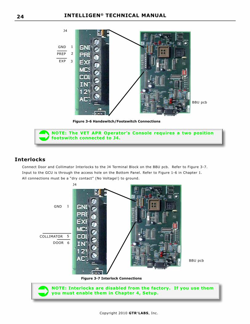
External Handswitch/FootswitchConnect an External Handswitch/Footswitch to the J4 Terminal Block on the BBU. Refer to Figure 3-6.
Input to the GCU is through the access hole on the Bottom Panel. Refer to Figure 1-6 in Chapter 1.
All connections must be a “dry contact” (No Voltage!) to ground.
INTELLIGEN® TECHNICAL MANUAL 24
Copyright 2010 GTRLABS, Inc.
2
3
PREP
EXP
GND
Figure 3-6 Handswitch/Footswitch Connections
BBU pcb
J4
1
NOTE: The VET APR Operator’s Console requires a two position footswitch connected to J4.
InterlocksConnect Door and Collimator Interlocks to the J4 Terminal Block on the BBU pcb. Refer to Figure 3-7.
Input to the GCU is through the access hole on the Bottom Panel. Refer to Figure 1-6 in Chapter 1.
All connections must be a “dry contact” (No Voltage!) to ground.
1
5
6DOOR
COLLIMATOR
GND
Figure 3-7 Interlock Connections
BBU pcb
J4
NOTE: Interlocks are disabled from the factory. If you use them you must enable them in Chapter 4, Setup.

25INTELLIGEN® TECHNICAL MANUAL
Copyright 2010 GTRLABS, Inc.
NOTE: AEC is active only if the specific option is installed.
AECConnect Ion Chambers to input connectors on Bottom Panel of GCU. Refer to Figure 3-8.
NOTE: Ion Chamber selection is based upon configuration programming in Chapter 4: Setup.
Figure 3-8 AEC Ion Chamber Connections
AEC #1/Bucky 1AEC #2/Bucky 2
AEC #3/No Bucky
Bottom Panel
NOTE: The AEC circuitry is compatible with positive slope Ion Chambers only.
Auxillary RelayAn Auxillary Relay is provided on the SPB pcb. This relay may be used to switch on power to other devices in the x-ray room (ie. table, tube stand, etc.).
Two sets of normally open contacts are provided at J3 on the SPB pcb (refer to Figure 3-9). These contacts close after a normal power up sequence.
NOTE: The maximum rating for the relay contacts is 8 Amps @ 250 VAC.
WARNING: For safety and compliance with the National Electrical Code, you must provide fuse protection for any voltage switched by this Auxillary Relay.

INTELLIGEN® TECHNICAL MANUAL 26
Copyright 2010 GTRLABS, Inc.
Figure 3-9 J3 Auxillary Relay ConnectionsSPB pcb
J3
4
3
1
COM 2
2
N.O. 2
COM 1
N.O. 1
Figure 3-10 24VAC Transformer
24 VAC Collimator Lamp PowerA step-down transformer is supplied, mounted to the Wall Mount Bracket, for 24 VAC Collimator Lamp Power. (Refer to Figure 3-10).
Input power for this transformer comes from the SPB pcb and is present after a normal power up sequence.
Output power is 24 VAC @ 8 Amps.
NOTE: The primary connections for the transformer are not connected during shipping. They must be connected after the wall mount bracket has been mounted to the wall and the GCU Chassis has been re-installed.
24 VAC Output
208 VAC Input
External Exposure IndicationAn open collector output is provided at J4-8 on the BBU pcb for an external exposure indication. Refer to Figure 3-11.
The output is active low and is present during an exposure sequence.
The output has a minimum on time of 75 milliseconds.
WARNING: The maximum rating for this open collector output is 30 VDC @ 100 mA. If the device you attach requires a higher rating, use this output to energize a relay.

27INTELLIGEN® TECHNICAL MANUAL
Copyright 2010 GTRLABS, Inc.
External ExposureIndication
7
Figure 3-11 External Exposure Indication
1
8BBU pcb
J4
GND
Vet Footswitch for “One Touch” Operation
Connect an External Single Position Footswitch to the J4 Terminal Block on the BBU. Refer to Figure 3-13. Input to the GCU is through the access hole on the Bottom Panel. Refer to Figure 1-6 in Chapter 1. All connections must be a “dry contact” (No Voltage) to ground.
In Setup Mode at Setup Location [≡28] enter a 1. This puts the generator in the “One Touch” mode. The first press of the footswitch initiates a PREP cycle which will last for 20 seconds. During this PREP cycle, the next press on the footswtich makes the exposure.
2
3“One Touch”
GND
Figure 3-13 VET Footswtich connection for “One Touch” Operation
BBU pcb
J4
1

INTELLIGEN® TECHNICAL MANUAL 28
Copyright 2010 GTRLABS, Inc.
Power On Test
NOTE: This test presumes you have performed the Inspection and Interconnection steps detailed in Chapter 2 of this manual. If you have not performed these steps please return to Chapter 2 and complete them at this time.
Chapter 4: Setup
OverviewThis chapter covers the initial Power On Test, selecting the mA Stations, initializing all preset variables and testing the Filament.
CAUTION: The generator is shipped with DIP1-1 on the BBU pcb in the OFF position. This disables the drive to the TEC pcb as well as the Pre-Charge and Charge relays. Do not move this switch to the ON position until directed to do so in this manual.
In addition to the Self-Diagnostic functions built into the generator, there are several additional safety features. One of these is the Diagnostic Interlock. This Diagnostic Interlock allows the microprocessors to detect if the HV Tank feedback cable is disconnected.
On Power Up if the HV Tank feedback cable is disconnected you will have an Error Code E01 displayed on the kVp Dis-play of the Operator’s Console.
CAUTION: Do not operate the generator with any of the circuit boards, the HVT, or the Operator’s Console disconnected.
DIP1-1
Figure 4-1 BBU pcb
Blue Watch Dog LED
The Blue Watch Dog LED on the BBU pcb provides additional information. When the Line Disconnect is first turned on the LED will illuminate for approximately 2 to 4 seconds. During this time the processor is initializing and you cannot turn on the Operator’s Console. At the end of this initialization period, the Blue Watch Dog LED will go out.
When you press the On/Off Pushbutton on the Operator’s Console the Blue Watch Dog LED will illuminate and stay on as long as the Console is on and there are no errors. If an error occurs, in addition to the Error Code being displayed in the kVp Display of the Operator’s Console, the Blue Watch Dog LED will blink the number of times corresponding to the Error Code.
Power On
Switch on the wall disconnect. The Blue Watch Dog LED should illuminate steady for approximately 2 to 4 seconds and then go out. This indicates a normal power up sequence for the processor.
WARNING: DANGER: When the wall disconnect is switched on, 208 VAC stand-by power is present on the SPB pcb even if the Operator’s Console is switched off. Lethal voltages are present on the pcb and care should be taken to avoid electrical shock.
29INTELLIGEN® TECHNICAL MANUAL
Copyright 2010 GTRLABS, Inc.
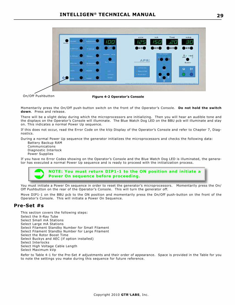
Figure 4-2 Operator’s ConsoleOn/Off Pushbutton
Momentarily press the On/Off push-button switch on the front of the Operator’s Console. Do not hold the switch down. Press and release.
There will be a slight delay during which the microprocessors are initializing. Then you will hear an audible tone and the displays on the Operator’s Console will illuminate. The Blue Watch Dog LED on the BBU pcb will illuminate and stay on. This indicates a normal Power Up sequence.
If this does not occur, read the Error Code on the kVp Display of the Operator’s Console and refer to Chapter 7, Diag-nostics.
During a normal Power Up sequence the generator initializes the microprocessors and checks the following data:Battery Backup RAMCommunicationsDiagnostic InterlockPower Supplies
If you have no Error Codes showing on the Operator’s Console and the Blue Watch Dog LED is illuminated, the genera-tor has executed a normal Power Up sequence and is ready to proceed with the initialization process.
NOTE: You must return DIP1-1 to the ON position and initiate a Power On sequence before proceeding.
You must initiate a Power On sequence in order to reset the generator’s microprocessors. Momentarily press the On/Off Pushbutton on the rear of the Operator’s Console. This will turn the generator off.
Move DIP1-1 on the BBU pcb to the ON position and momentarily press the On/Off push-button on the front of the Operator’s Console. This will initiate a Power On Sequence.
Pre-Set #sThis section covers the following steps:Select the X-Ray Tube Select Small mA StationsSelect Large mA StationsSelect Filament Standby Number for Small FilamentSelect Filament Standby Number for Large FilamentSelect the Rotor Boost TimeSelect Buckys and AEC (if option installed)Select InterlocksSelect High Voltage Cable LengthSelect Maximum kVpRefer to Table 4-1 for the Pre-Set # adjustments and their order of appearance. Space is provided in the Table for you to note the settings you make during this sequence for future reference.

INTELLIGEN® TECHNICAL MANUAL 30
Copyright 2010 GTRLABS, Inc.
Pre-Set # Description Factory Setting Notes
0 0 X-Ray Tube Selection 0
0 1 1st mA Station, 25mA 1
0 2 2nd mA Station, 50mA 1
0 3 3rd mA Station, 75mA 1
0 4 4th mA Station, 100mA 1
0 5 5th mA Station, 150mA 2
0 6 6th mA Station, 200mA 2
0 7 7th mA Station, 250mA 2
0 8 8th mA Station, 300mA 2
0 9 9th mA Station, 400mA 2
1 0 10th mA Station, 500mA 2
1 1 11th mA Station, 600mA 2
1 2 FIL Standby # (Small) 200
1 3 FIL Standby # (Large) 200
1 4 HV Cable Length 15
1 5 Bucky 1 Select 0 *
16 Bucky 2 Select 0 *
17 AEC - No Bucky Select 0 *
18 AEC - Bucky 1 Select 0 *
19 AEC - Bucky 2 Select 0 *
21 Maximum kVp **
22 Rotor Speed 50/60/180
23 Low Speed Boost Time ***
24 Tube Thermal Interlock 0
25 Collimator Interlock 0
26 Door Interlock 0
27 Software Version
32 kVp Feedback Test
Table 4-1 Pre-Set Number Selection
* Only available on the i-325/425 if the option is installed. If the option is not in-stalled, these numbers will not move.
** 125 kVp for the i-325/425.
*** 1.7 sec for the i-325/425.

31INTELLIGEN® TECHNICAL MANUAL
Copyright 2010 GTRLABS, Inc.
With the generator on and no Error Codes showing on the Operator’s Console, momentarily press the Service Push Button. Refer to Figure 4-5.
Figure 4-5 Location of SERVICE Push Button
BBU pcb
Service
Push Button
This puts the generator in the Set Up mode. The mAs Display on the Operator’s Console becomes the Pre-Set # Display.
The first character will display this symbol [≡]. Refer to Figure 4-6.
Pressing the Up/Down push-buttons associated with the mAs Display allows you to scroll forward and reverse through the Pre-Set # selections.
The selection values associated with each individual Pre-Set # are displayed on the Time Display. Pressing the Up/Down push-buttons associated with the Time Display allows you to change the value in memory for that Pre-Set #.
CAUTION: The value displayed on the Time Display is the value in memory for that Pre-Set #. Take care not to accidently change any of the values.

INTELLIGEN® TECHNICAL MANUAL 32
Copyright 2010 GTRLABS, Inc.
Figure 4-6 APR Operator’s Console SERVICE Configuration
Displays Pre-Set #
Scrolls Forward & Reverse
DisplaysPre-Set # ValueDisplays kVp
(when required)
Displays mA (when required)
NOTE: The VET APR Operator’s Console requires a two position footswitch connected to J4.
X-Ray Tube Selection
When you enter the SERVICE Mode, the first Pre-Set # which appears in the mAs Display is the X-Ray Tube Selection #
[≡00]. The Factory Setting for this value (as displayed in the mA Display) is [0]. With a [0] showing in theTime Display you have the default x-ray tube selected. This tube is a generic tube used for testing and shipping.
Do not leave this setting at [0]. Select the x-ray tube you are using from Table 4-2. If your tube is not listed on the table, select a tube with similar filament characteristics.
WARNING: If the x-ray tube you are using is not listed in Table 4-2 and there is no tube in the table with similar filament characteristics, do not proceed. Tube protection is only available with the tubes listed in Table 4-2 or tubes with similar filament characteristics. Failure to heed this WARNING may result in catastrophic failure of the x-ray tube.
Use the Up/Down push-buttons for the Time Display to scroll forward and reverse through the available X-Ray Tube numbers.
When you have the X-Ray Tube you want selected, use the Up/Down push-buttons for the mAs Display to proceed to the next Pre-Set #.
The tube number will be stored automatically.

33INTELLIGEN® TECHNICAL MANUAL
Copyright 2010 GTRLABS, Inc.
Table 4-2 X-Ray Tube Selection
NOTE: 50 Hz data is not available for some x-ray tubes. If you have selected (50) for Setup location [≡22], you cannot select an x-ray tube unless an “X” appears in the 50Hz column.
#ebuT noitpircseD topSlacoF zH05 zH06 zH081
00 44DARakeruE 0.2/0.1 X X X
10 8DARakeruE 0.2/0.1 X X
20 9DARakeruE 5.1/6.0 X X
30 31DARakeruE 0.2/0.1 X X
40 41DARakeruE 2.1/6.0 X X X
50 41DARakeruE 5.1/6.0 X X X
60 61DARakeruE 0.2/0,1 X X X
70 02DARakeruE 2.1/6.0 X X
80 b12DARakeruE 2.1/6.0 X X X
90 b04DARakeruE 0.1/6.0 X X
01 c04DARakeruE 2.1/6.0 X X
11 d04DARakeruE 5.1/6.0 X X
21 44DARakeruE 0.2/0.1 X X X
31 a55DARakeruE 2.1/6.0 X X
41 b55DARakeruE 5.1/6.0 X X
51 65DARakeruE 0.1/6.0 X X
61 652ACAMIE 0.1/6.0 X X X
71 292ACAMIE 2.1/6.0 X X X
81 614ACAMIE 0.2/0.1 X X
*NOTE: Th is tube has a fixed anode and is rated at 5 kW. Selecting this tube automatical ly disables the rotor circuit and sets 5 kW as maximum output (100 kVp @ 50 mA).
#ebuT noitpircseD topSlacoF zH05 zH06 zH081
91 294ACAMIE 2.1/6.0 X X
02 201ACAMIE 0.2/0.1 X X X
12 231ACAMIE 2.1/6.0 X X X
22 291CAMIE 2.1/6.0 X X X
32 9327EabihsoT 0.2/0.1 X X X
42 °5.21-001yarixaMEG 52.1/6.0 X X X
52 °5.21-001yarixaMEG 5.1/6.0 X X X
62 °5.21-001yarixaMEG 0.1/6.0 X X X
72 47DARakeruE 5.1/6.0 X X X
82 2427EabihsoT 5.1/6.0 X X
92 292GCAMIE 2.1/6.0 X X
03* 4-501/XO.I.E.C 6,2 X X
13 051-05/03-9IDTEMOC X X
23 24-XUXEDNEG 5.1/6.0 X X
33 1ARDLEB 0.2/2.1 X
43 0427EabihsoT 2.1/6.0 X X
53 2527EabihsoT 2.1/6.0 X X X
63 86DAR 2.1/6.0 X X
73 86DAR 0.2/0.1 X X
83 0321ORspilihP 2.1/6.0 X X

INTELLIGEN® TECHNICAL MANUAL 34
Copyright 2010 GTRLABS, Inc.
mA Station SelectionYou have a maximum of 11 mA Stations which you can program on the V-50/V-650 generator, 10 on the V-40/V-550, 9 on the V-30/V-425, 8 on the V-20/V325 and 7 on the V-10.
You may use any combination between the large and the small filaments.
NOTE: In the Time Display there are three (3) numbers which will be displayed.
0 Not Programmed or Not Available 1 Progammed on Small Filament 2 Programmed on Large Filament
Small mA Station Selection
Review the factory settings in Table 4-1. If the settings are ok no further action is required.
If you wish to make a change in any of the selections use the following procedure.
With the Setup Location for the mA station showing in the mAs display, select the desired programming in the mA display.
Your options are:
0 Not Programmed or Not Available 1 Progammed on Small Filament 2 Programmed on Large Filament
Large mA Station Selection
Review the factory settings in Table 4-1. If the settings are ok no further action is required.
If you wish to make a change in any of the selections use the following procedure.
With the Setup Location for the mA station showing in the mAs display, select the desired programming in the mA display.
Your options are:
0 Not Programmed or Not Available 1 Progammed on Small Filament 2 Programmed on Large Filament
Filament Standby NumberThe generator has the capability of adjusting the standby current through the large and small filaments independently of each other.
The filament standby current is adjusted by increasing or decreasing the number displayed on the Time Display of the Operator’s Console during Set Up.
This number does not directly correlate to an actual amount of filament current. It is subjective and the adjustment procedure is augmented by visually inspecting each filament and monitoring the FIL I test point on the BBU pcb as you make the adjustment.
Figure 4-7 FIL I Test PointFIL I Test Point
GND

35INTELLIGEN® TECHNICAL MANUAL
Copyright 2010 GTRLABS, Inc.
NOTE: The range of filament numbers for Standby is [0] to [230]. The Factory Setting is [200]. Since filament characteristics vary from x-ray tube to x-ray tube it is strongly recommended that you return this value to [200] when replacing an x-ray tube.
CAUTION: Monitor the FIL I test point on the BBU pcb during Filament Standby Number adjustment. Do not exceed the maximum allowable filament current for the focal spot you are adjusting. At the FIL I test point, 1 VDC = 1.3 Amp Filament Current.
Small Filament Standby NumberUsing the Up/Down push-buttons for the mAs Display, scroll through the Pre-Set #s until you have [≡12] displayed on the mAs Display. Monitor the FIL I test point on the BBU pcb with a Digital Voltmeter or an oscilloscope. 1 VDC = 1.3 Am.
Using the Up/Down push-buttons for the Time Display, increase the Filament Number until the filament begins to il-luminate. Determine that you are adjusting the Small Filament by visual inspection.
Continue adjusting the number until the filament is bright enough.In no case should the FIL I exceed 2.75 Amps. Record this value in Table 4-1 for future reference.
Large Filament Standby NumberUsing the Up/Down push-buttons for the mAs Display, scroll through the Pre-Set #s until you have [≡13] displayed on the mAs Display.
Monitor the FIL I test point on the BBU pcb with a Digital Voltmeter or an oscilloscope. 1 VDC = 1.3 Amp.
Using the Up/Down push-buttons for the Time Display, increase the Filament Number until the filament begins to il-luminate.
Determine that you are adjusting the Large Filament by visual inspection.
Continue adjusting the number until you reach a maximum of 2.75 Amps or the Large Filament is bright enough.
Record this value in Table 4-1 for future reference.
HV Cable LengthThe length of the HV Cables is a factor in the shape of the kVp waveform.
This effect is non-linear and more pronounced at the lower kW levels.
The generator compensates for this effect automatically.
With Pre-Set # [≡14] showing in the mAs Display, select the approximate length of the HV Cables connected to the generator using the Up/Down push-buttons for the Time Display. The length is displayed in increments of 5 feet.
NOTE: For cable length not divisible in 5 feet increments, select the next lowest setting on the mA Display. For instance: for a cable length of 17 feet, select the setting of 15 feet on the Time Display.

INTELLIGEN® TECHNICAL MANUAL 36
Copyright 2010 GTRLABS, Inc.
Buckys and AEC SelectionThe generator will operate 2 Buckys and 3 Ion Chambers for AEC if the options are installed. Each of these functions can be programmed independently.
NOTE: For Pre-Set #s [≡15] and [≡16] you have three choices on the Time Display; [0], [1] and [2]. [0] = disabled, [1] = enabled (bucky) and [2] enabled (tomo).
NOTE: For Pre-Set #s [≡17] through [≡19] you have two choices on the Time Display; [0] or [1]. [0] = disabled, [1] = enabled.
NOTE: Bucky’s and AEC are active only if the specific option is installed.
Bucky 1 Select If you have connected a Bucky to the Bucky 1 position of J9 select a [1] for Pre-Set # [≡15]. For Tomo select a [2]. If none select a [0].
Bucky 2 SelectIf you have connected a Bucky to the Bucky 2 position of J9 select a [1] for Pre-Set # [≡16]. For Tomo select a [2]. If none select a [0].
AEC - No Bucky SelectThe generator has the capability of operating an Ion Chamber without the selection of a Bucky for table top, stretcher or wheel chair use.
This condition is selected by having both BKY 1 and BKY 2 LEDs not illuminated on the Operator’s Console.
The interconnection point for this Ion Chamber is AEC #3 on the Bottom Panel of the GCU (refer to Figure 1-6)
If you have connected an Ion Chamber to AEC #3 select a [1] for Pre-Set # [≡17]. If not select a [0].AEC - Bucky 1 Select
If you have connected an Ion Chamber to AEC #1 and it is installed in Bucky 1 select a [1] for Pre-Set # [≡18]. If not select a [0].
AEC - Bucky 2 SelectIf you have connected an Ion Chamber to AEC #2 and it is installed in Bucky 2 select a [1] for Pre-Set # [≡19]. If not select a [0].
Maximum kVpThe Maximum kVp selectable by the Operator can be programmed during Setup.
With Pre-Set # [≡21] showing in the mAs Display, select the Maximum kVp. The choices are 99 kVp, 125 kVp (V-10-/20/30) and 150 kVp (V-40/50). This selection represents the Maximum kVp the Operator will be permitted to select on the Operator’s Console during normal operation.
Rotor SpeedYou must select the Rotor Speed.
By selecting (50) for Pre-Set # [≡22] you configure the generator for 50Hz, Low Speed operation. In this configura-tion Pre-Set # [≡23] becomes a display of Rotor Boost Time.
By selecting (60) for Pre-Set # [≡22] you configure the generator for 60Hz, Low Speed operation. In this configura-tion Pre-Set # [≡23] becomes a display of Rotor Boost Time.
By selecting (180) for Pre-Set # [≡22] you configure the generator for High Speed operation. In this configuration Pre-Set # [≡23] has no function.
CAUTION: If you select (180) for Pre-Set# [≡22] you must have an External High Speed Starter connected to the AEC/HSS option pcb and the rotor connections must terminate in the External High Speed Starter, not on J9 of the SPB pcb.

37INTELLIGEN® TECHNICAL MANUAL
Copyright 2010 GTRLABS, Inc.
Low Speed Boost TimeWhen you press the PREP push-button there is a delay before the green PREP LED illuminates.
This delay is the Rotor Boost Time.
During this time the rotor is accelerated to approximately 3600 RPM, the filament is boosted to the correct temperature, all the interlocks are checked (including the rotor interlock) and the Pre-Charge and Charge sequences are initiated.
If you have selected (50) or (60) for Pre-Set# [≡22], you may select a Rotor Boost Time.
Using the Up/Down push-buttons for the mAs Display, scroll through the Pre-Set #s until you have [≡23] displayed on the mAs Display. The Factory Setting for this Pre-Set # is [1.7] sec. Select a value for Rotor Boost Time.
NOTE: The minimum value is [1.7] sec. This is the minimum time necessary for the filament temperature to stabalize when chang-ing from Standby to the mA Station selected for exposure.
Interlock Selection
The generator provides for two independent interlocks with LED Displays on the Operator’s Console.
They are Collimator Interlock and Door Interlock. In addition, there is a Thermal Interlock for the X-Ray Tube.
NOTE: For Tube Thermal Interlock, Collimator Interlock, and Door Interlock you have two choices on the Time Display; [0] or [1]. [0] = disabled, [1] = enabled.
Tube Thermal InterlockIf you have connected a Thermal Interlock for the X-Ray Tube to J9, pin 9 on the SPB pcb (refer to Figure 3-5) select a [1] for Pre-Set # [≡24]. If not select a [0].
Collimator InterlockIf you have connected a Collimator Interlock to J4, pin 5 on the BBU pcb (refer to Figure 3-7) select a [1] for Pre-Set # [≡25]. If not select a [0].
Door InterlockIf you have connected a Door Interlock to J4, pin 6 on the BBU pcb (refer to Figure 3-7) select a [1] for Pre-Set # [≡26]. If not select a [0].
Software Version Pre-Set # [≡27] will indicate the Software Version of the generator.
NOTE: This completes the Setup section of the Technical Manual. Advance the Pre-Set # showing in the mAs Display to [≡32] and turn to Chapter 5: Calibration.
INTELLIGEN® TECHNICAL MANUAL 38
Copyright 2010 GTRLABS, Inc.
Chapter 5: Calibration
WARNING: The procedures detailed in
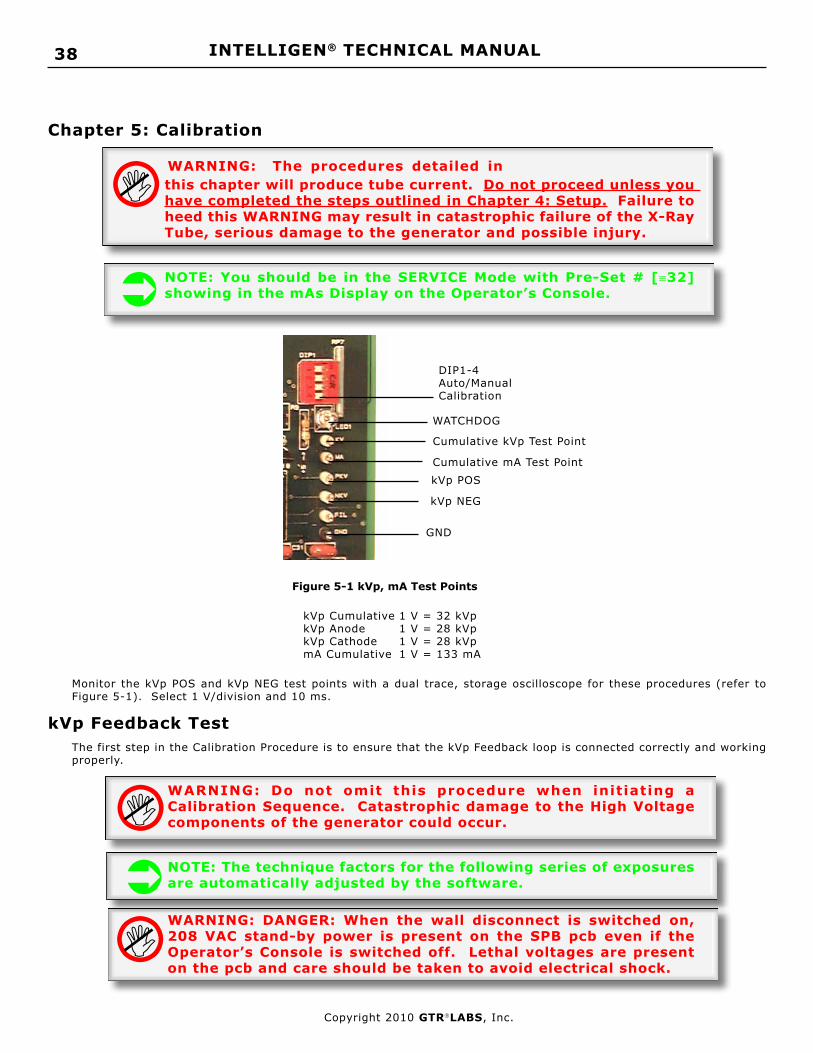
Figure 5-1 kVp, mA Test Points
Cumulative kVp Test Point
Cumulative mA Test Point
DIP1-4Auto/ManualCalibration
kVp Cumulative 1 V = 32 kVp kVp Anode 1 V = 28 kVp kVp Cathode 1 V = 28 kVp mA Cumulative 1 V = 133 mA
kVp POS
kVp NEG
GND
WATCHDOG
Monitor the kVp POS and kVp NEG test points with a dual trace, storage oscilloscope for these procedures (refer to Figure 5-1). Select 1 V/division and 10 ms.
kVp Feedback TestThe first step in the Calibration Procedure is to ensure that the kVp Feedback loop is connected correctly and working properly.
WARNING: Do not omit this procedure when initiating a Calibration Sequence. Catastrophic damage to the High Voltage components of the generator could occur.
NOTE: The technique factors for the following series of exposures are automatically adjusted by the software.
WARNING: DANGER: When the wall disconnect is switched on, 208 VAC stand-by power is present on the SPB pcb even if the Operator’s Console is switched off. Lethal voltages are present on the pcb and care should be taken to avoid electrical shock.
this chapter will produce tube current. Do not proceed unless you have completed the steps outlined in Chapter 4: Setup. Failure to heed this WARNING may result in catastrophic failure of the X-Ray Tube, serious damage to the generator and possible injury.
NOTE: You should be in the SERVICE Mode with Pre-Set # [≡32] showing in the mAs Display on the Operator’s Console.

39INTELLIGEN® TECHNICAL MANUAL
Copyright 2010 GTRLABS, Inc.
NOTE: During this test there is no tube current. The kVp waveforms will have a long “tail” on them due to slow cable discharge. This is normal.
WARNING: If the kVp is not within the limits specified, or if you get an Error Code on the kVp Display of the Operator’s Console, do not proceed. This indicates a problem in the kVp Feedback circuitry and must be corrected before any further exposures are made.
Release the PREP and EXP push-buttons.
If the kVp waveforms are within the limits specified, proceed to Calibration.
Calibration
NOTE: During the Calibration Procedure each selected mA station is adjusted at different kVp Set Points. This procedure establishes mA linearity. During calibration, exposures for the higher mA stations will be made at kVp Set Points including 100 kVp, 120 kVp and 140 kVp (V-40/50) regardless of the generator power rating. These exposures are limited to 10 milliseconds and have no relationship to the maximum kW output of the generator.
The generator has two calibration modes: Manual Calibration and AUTOCAL.
In the Manual Calibration mode the Service Engineer selects each programmed mA station and each kVp set point manually. At each of these points he can make exposures and adjust the Filament Number manually.
In the AUTOCAL mode the Service Engineer selects each programmed mA station manually and the generator operat-ing system makes exposures and adjusts the Filament Number automatically for each kVp set point.
The generator is shipped in the Manual Calibration mode. DIP1-4 on the BBU pcb is in the OFF position (refer to Figure 5-1). To select the AUTOCAL mode, move DIP1-4 to the ON position.
You may switch between Manual Calibration and AUTOCAL at any time during the Calibration procedure.
During this test the Time Display will indicate the DC Voltage charge on the Storage Capacitors and the kVp Display will
show the test kVp. With Pre-Set # [≡32] showing on the mAs Display of the Operator’s Console, the capacitor volt-age level [100] will be showing on the Time Display. The kVp Display will show the kVp value for the test (50 kVp).
With Pre-Set # [≡32] showing on the mAs Display of the Operator’s Console, press and hold the PREP push-button.
NOTE: The VET APR Operator’s Console requires a two position footswitch connected to J4.
The following sequence of events will be initiated:The Discharge Relay will be disabled.The Pre-Charge Relay will be energized momentarily until approximately 100 VDC is indicated on the storage capaci-tors.The Charge Relay will be disabled.The Rotor will boost and begin to run.The green Ready LED in the PREP push-button will illuminate.Press the EXP push-button and monitor the kVp waveforms on the oscilloscope. The kVp POS should be 25 kVp +/- 5 kVp and the kVp NEG should be 25 kVp +/- 5 kVp.
NOTE: Only make one exposure. If you must make another exposure for any reason, release the PREP and EXP push-buttons momentarily and start the sequence again.

INTELLIGEN® TECHNICAL MANUAL 40
Copyright 2010 GTRLABS, Inc.
NOTE: You should monitor the Cumulative kVp and mA test points during the calibration sequence. Take note of any irregularities in either waveform and note the values indicated.
CAUTION: If you encounter any difficulty during the calibration sequence, refer to Chapter 7: Diagnostics for assistance.
Figure 5-2a Standard Operator’s Console Calibration Configuration
Pre-Set #Filament NumberkVp Setpoint
Filament # Adjust
kVp Setpoint Adjust
mA Station
Pre-Set # Adjust
NOTE: The VET APR Console requires a two position footswitch for PREP and EXPOSE.

41INTELLIGEN® TECHNICAL MANUAL
Copyright 2010 GTRLABS, Inc.
Table 5-1 Calibration Pre-Set #s
NOTE: The filament numbers in all the kVp Set Point locations for the mA stations were entered during Final Test at the factory. Your numbers will be different for the x-ray tube you are calibrating.
#teS-erP noitpircseD 04pVk
05pVk
07pVk
001pVk
021pVk
041pVk
33 noitatSAm52
43 noitatSAm05
53 noitatSAm57
63 noitatSAm001
7377 noitatSAm051
83 noitatSAm002
93 noitatSAm052
04 noitatSAm003
14 noitatSAm004
24 noitatSAm005
34 noitatSAm006
Table 5-2 Voltage Readings at mA Composite Test Point
on DIB for each mA Station
noitatSAmtseTAmtnioPegatloV
noitatSAmtseTAmtnioPegatloV
Am52 91.0 Am052 88.1
Am05 83.0 Am003 52.2
Am57 65.0 Am004 00.3
Am001 57.0 Am005 57.3
Am051 31.1 Am006 05.4
Am002 05.1

INTELLIGEN® TECHNICAL MANUAL 42
Copyright 2010 GTRLABS, Inc.
Manual Calibration The Manual Calibration mode provides for manual selection of each mA station and kVp set point and manual adjust-ment of the Filament Numbers for each programmed mA station to produce the correct mA.
Tube Protection is automatic and is based upon the selection of the x-ray tube in Pre-Set # [≡00]. Press the SERVICE pushbutton on the BBU pcb to put the generator into the SERVICE mode.
Using the Up/Down push-buttons for the mAs Display, advance the Pre-Set # until you have the first programmed mA station displayed on the mAs Display. (Refer to Table 5-1.) The Time Display will show the Filament Number.
NOTE: The range of Filament Numbers is 0 to 999, depending upon the size of the filament.
The kVp Display will show the first kVp set point (refer to Figure 5-2). The mA Display will show the mA Station.
Press and hold the PREP push-button. When the green READY LED is illuminated make an exposure by pressing the EXP push-button.
Adjust the Filament Number (up or down as required) and make another exposure and read the mA.
Continue until you have completed calibration for this mA station on all the kVp set points.
Using the Up/Down push-buttons for the mAs Display advance to the next Pre-Set # corresponding to the next pro-grammed mA station. (Refer to Table 5-1).
Adjust the Filament Number for each kVp set point in turn until you have completed calibration for this mA station.
Continue until you have adjusted the correct mA for each mA station and each kVp set point programmed.
AUTOCALThe AUTOCAL mode provides for manual selection of each programmed mA station and automatic adjustment of the Filament Numbers at each kVp set point to produce the correct mA.
The generator is shipped in the Manual Calibration mode. DIP1-4 on the BBU pcb is in the OFF position (refer to Figure 5-1).
To select the AUTOCAL mode, move DIP1-4 to the ON position. Press the SERVICE pushbutton on the BBU pcb to put the generator into the SERVICE mode.
Tube Protection is automatic and is based upon the selection of the x-ray tube in Pre-Set # [≡00].
Using the Up/Down push-buttons for the mAs Display, advance the Pre-Set # until you have the first programmed mA station displayed on the mAs Display. (Refer to Table 5-1.)
The Time Display will show the Filament Number.
NOTE: The range of Filament Numbers is 0 to 999, depending upon the size of the filament.
The kVp Display will show the first kVp set point (refer to Figure 5-2). The mA Display will show the mA Station
Press and hold the PREP push-button. When the green READY LED is illuminated, press and hold the EXP push-but-ton.
The generator will begin a series of exposures controlled by the operating system. The mA value will be sampled and the Filament Number will be adjusted up or down as required.
This process will continue until the correct mA level is reached for the selected kVp set point.
The generator will then select the next kVp set point and continue the process.
This will continue (as long as the PREP and EXP push-buttons are pressed) until the mA value at the last kVp set point is correct.
The generator will stop making exposures.
Release the PREP and EXP push-buttons and select the next programmed mA station by using the Up/Down push-buttons for the mAs Display.
Press and hold the PREP and EXP push-buttons to begin the AUTOCAL sequence for the selected mA station.
Continue this process until you have completed the AUTOCAL sequence for each programmed mA station.

43INTELLIGEN® TECHNICAL MANUAL
Copyright 2010 GTRLABS, Inc.
AEC Density AdjustEach Ion Chamber connected to generator can be adjusted independently for density and skew.
There are 6 Pre-Set #s associated with the AEC Density Adjust procedure, 2 for each Ion Chamber. (Refer to Table 5-3.)
NOTE: AEC is active only if the specific option is installed.
NOTE: The Pre-Set #s indicated in Table 5-3 will not be active unless you selected a [1] for Pre-Set#s [≡17], [≡18], [≡19] in Chapter 4: Setup.
The following procedure applies to each Ion Chamber connected to the generator.
Select 80 kVp, and a Back-Up Time. Select an mA station appropriate for the density phantom you use.
Select 0 Density on the Operator’s Console and Bucky 1, Bucky 2 or No Bucky as appropriate.Make an exposure and read the density of the film.
NOTE: You cannot make an exposure in the Service Mode with one of the AEC Pre-Set #s showing on the Time Display. You must exit the Service Mode to make the exposure and re-enter the Service Mode to make density and skew adjustments.
WARNING: During the calibration procedure (Manual or AUTOCAL) the generator is monitoring % Heat Units in the anode of the x-ray tube. When the % Heat Units reaches 85% a pulsed tone will sound continuously. Exposures are prohibited while this tone is sounding. Should you reach 85% Heat Units during the calibration procedure for the particular x-ray tube you are using, take a 15 minute time-out to allow the anode to dissipate the accumulated heat.
NOTE: The VET APR Console requires a two position footswitch for PREP and EXPOSE.
Density
Adjust Master Pot on Ion Chamber Up or Down as needed and Make Exposures until you have the desired Density at 80 kVp.
Tilt
Make an Exposure at 50 kVp and 100 kVp and read the Density. Adjust the Tilt Number until you have the same Density at 50 kVp, 80 kVp, and 100 kVp.
NOTE: The Tilt Number cannot be less than the Density Number nor more than twice the Offset Number.
NOTE: The maximum number for Tilt is 250.

INTELLIGEN® TECHNICAL MANUAL 44
Copyright 2010 GTRLABS, Inc.
teS-erP# noitpircseD yrotcaF
gnitteS setoN
44 ytisneDCEAykcuBoN 001
54 tliTCEAykcuBoN 001
64 ytisneDCEA1ykcuB 001
74 tliTCEA1ykcuB 001
84 ytisneDCEA2ykcuB 001
94 tliTCEA2ykcuB 001
Table 5-3 AEC Pre-Set #s
NOTE: For Use With Positive Slope ION Chambers Only
Figure 5-3 Pinout for AEC Connectors
Chapter 6: Compliance Testing
OverviewThe generator meets the requirements for DHHS Radiation performance standards for high voltage generators as de-tailed in Title 21 CFR, Chapter 1, Sub Chapter J, Section 1020 in effect as of the date of manufacture.
This chapter details the procedures necessary to ensure compliance with the performance standard.
The tests and inspections in this chapter should be performed:Upon initial installationOnce a year as part of a preventive maintenance inspectionAny time a major component is replaced
CAUTION: The generator is a sophisticated electronic device. All components are chosen for performance, quality and safety. Replacement should be confined to printed circuit boards or major components. Replacement of components other than those mounted in a socket (i.e. fuse, relay,) on a printed circuit board is not authorized as this may affect safety as well as performance standard compliance.
ConfigurationOperator’s Console
There are 2 Operator’s Consoles that are available with the VALUEGEN® family of generators that require Compliance Testing.
They are:
Standard Operator’s Console (Part Number 6065.00)
APR Operator’s Console (Part Number 6072.00)

45INTELLIGEN® TECHNICAL MANUAL
Copyright 2010 GTRLABS, Inc.
Figure 5-3 Pinout for AEC Connectors
Standard Operator’s Console
1. kVp Display 2. mA Display 3. Time Display 4. mAs Display 5. kVp Up/Down 6. mA Up/Down 7. Time Up/Down 8. mAs Up/Down 9. AEC Density Up/Down10. BKY Select
11. EXP12. PREP13. AEC Field Select14. AEC Reset15. Overload LED16. Collimator LED17. Interlock LED18. On/Off19. Hand Switch20. Connector
Figure 6-1A Standard Operator’s Console (Front View)
Figure 6-1B Standard Operator’s Console (Rear View)
1 2 3 4
5 6 7 8
9
10
11121314151618 17
20 19
NOTE: Based upon selections made in Chapter 4: Setup, some of the following tests may not be applicable.

INTELLIGEN® TECHNICAL MANUAL 46
Copyright 2010 GTRLABS, Inc.
Refer to Figure 6-1A&B for the following tests.On/Off
Press and release the On/Off push-button [18] on the Operator’s Console .
The system should come on and all LEDs in the four displays should illuminate and the Beep should sound.
There should not be an Error Code displayed in the kVp Display.kVp Display and Up/Down
There should be a value between 40 and 125 displayed on the kVp Display [1].
Press kVp Up and kVp Down [5]. The display should increase and decrease.mA Display and Up/Down
There should be an mA value showing on the mA Display [2].
Press mA Up and mA Down [6]. The display should increase and decrease. The decimal point in the lower right of the display will illuminate to indicate Large Focal Spot.
Time Display and Up/DownThere should be a Time value showing on the Time Display [3].
Press Time Up and Time Down [7]. The display should increase and decrease. The decimal point will change to indicate milliseconds, tenths and whole seconds.
mAs Display and Up/DownThere should be an mAs value showing on the mAs Display [4].
Press mAs Up and mAs Down [8]. The display should increase and decrease. The decimal point will change to indicate portions or whole mAs.
Interlock LEDOpen the external interlock connected to Pin 6 of J4 on the BBU pcb.
The Interlock LED [17] should be illuminated and PREP should be inhibited.
Close the Interlock.
The Interlock LED [17] should not be illuminated and PREP should be functional.Collimator LED
Open the collimator interlock connected to Pin 5 of J4 on the BBU pcb.
The Collimator LED [16] should be illuminated and PREP should be inhibited.
Close the Interlock
The Collimator LED [16] should not be illuminated and PREP should be functional.Overload LED
Increase the kVp, mA and Time to the maximum indications for each display.
Observe the Overload LED [15].
If the exposure factors selected exceed the maximum ratings for the x-ray tube selected, this LED should be illuminated and PREP should be inhibited.
PREPPress and hold PREP [12].
The rotor should turn and after the programmed Rotor Boost Time, the green PREP LED should illuminate indicating an exposure is possible.
EXPSelect 50 kVp, the smallest mA programmed and 1.0 sec Time.
Press and hold PREP [12].
When the green PREP LED illuminates, press and hold EXP [11].
The red EXP LED should illuminate and an audible tone should sound to indicate an exposure in progress.
Release EXP before the selected time expires.
The exposure should stop, the red EXP LED should extinguish and the audible tone should stop.
Press and hold EXP again.
Another exposure should begin.
At the end of the selected time the exposure should stop.
Release PREP and EXP.
Press and hold EXP only.
There should be no indication and no exposure.

47INTELLIGEN® TECHNICAL MANUAL
Copyright 2010 GTRLABS, Inc.
BKY
Bky 1Press the BKY switch [10] until the Bky 1 LED is illuminated. Select 50 kVp, the smallest mA station programmed and .25 secs on the Time Display.Make an exposure and observe the Bucky connected to Bky 1. The Bucky should oscillate and the exposure should occur normally.
Bucky 2Press the BKY switch [10] until the Bky 2 LED is illuminated.Select 50 kVp, the smallest mA station programmed and .25 secs on the Time Display.Make an exposure and observe the Bucky connected to Bky 2. The Bucky should oscillate and the exposure should occur normally.
No BuckyPress the BKY switch [10] until the Bky 1 and Bky 2 LEDs are not illuminated.Select 50 kVp, the smallest mA station programmed and .25 secs on the Time Display.Make an exposure and observe the Buckys connected to the generator.The Buckys should not oscillate and the exposure should occur normally.
AEC DensityOne of the LEDs in the AEC Density Display should be illuminated.Press AEC Density Up and AEC Density Down [9]. The LEDs should indicate a full range between -2 to +2 Density.
AEC Reset/600 MAS LimitSelect 50 kVp, the maximum mA programmed and a backup Time to exceed 600 MAS. (i.e. if 300 mA then 2.5 sec)
NOTE: If your x-ray tube will not allow a technique that will exceed 600 MAS, ignore this step.
Close the collimator.Make an exposure and observe that the AEC Reset LED illuminates and flashes.While flashing, PREP and EXP are inhibited.Press the AEC Reset push-button [14] and the LED ceases to flash and is extinguished.
AEC Field Select Press and release FIELD (13) switches to select or de-select the appropriate field. The LEDs will illuminate to indicate field selection.

INTELLIGEN® TECHNICAL MANUAL 48
Copyright 2010 GTRLABS, Inc.
NOTE: Based upon selections made in Chapter 4: Setup, some of the following tests may not be applicable.
Refer to Figure 6-1A&B for the following tests.On/Off
Press and release the On/Off push-button [18] on the Operator’s Console .
The system should come on and all LEDs in the five displays should illuminate and the Beep should sound.
There should not be an Error Code displayed in the kVp Display.
1. kVp Display 2. mA Display 3. Time Display 4. mAs Display 5. kVp Up/Down 6. mA Up/Down 7. Time Up/Down 8. mAs Up/Down 9. AEC Density Up/Down
10. BKY Select11. EXP12. PREP13. AEC Field Select14. AEC Reset15. Overload LED16. Collimator LED17. Interlock LED18. On/Off
Figure 1-1A APR Operator’s Console (Front View)
Figure 1-1B APR Operator’s Console (Rear View)
APR Operator’s Console 1 2 3 4
5 6 7 8
9
10
11121314
151618
17
21 22 2324
2526
20 19
19. Hand Switch20. Connector21. Store22. APR Selections23. Centimeter Display24. Centimeter Up/Down25. Film/Screen Select26. A/P-Lateral-Other

49INTELLIGEN® TECHNICAL MANUAL
Copyright 2010 GTRLABS, Inc.
kVp Display and Up/Down There should be a value between 40 and 125 displayed on the kVp Display [1].
Press kVp Up and kVp Down [5]. The display should increase and decrease.mA Display and Up/Down
There should be an mA value showing on the mA Display [2].
Press mA Up and mA Down [6]. The display should increase and decrease. The decimal point in the lower right of the display will illuminate to indicate Large Focal Spot.
Time Display and Up/DownThere should be a Time value showing on the Time Display [3].
Press Time Up and Time Down [7]. The display should increase and decrease. The decimal point will change to indicate milliseconds, tenths and whole seconds.
mAs Display and Up/DownThere should be an mAs value showing on the mAs Display [4].
Press mAs Up and mAs Down [8]. The display should increase and decrease. The decimal point will change to indicate portions or whole mAs.
Interlock LEDOpen the external interlock connected to Pin 6 of J4 on the BBU pcb.
The Interlock LED [17] should be illuminated and PREP should be inhibited.
Close the Interlock.
The Interlock LED [17] should not be illuminated and PREP should be functional.Collimator LED
Open the collimator interlock connected to Pin 5 of J4 on the BBU pcb.
The Collimator LED [16] should be illuminated and PREP should be inhibited.
Close the Interlock
The Collimator LED [16] should not be illuminated and PREP should be functional.Overload LED
Increase the kVp, mA and Time to the maximum indications for each display.
Observe the Overload LED [15].
If the exposure factors selected exceed the maximum ratings for the x-ray tube selected, this LED should be illuminated and PREP should be inhibited.PREP
Press and hold PREP [12].
The rotor should turn and after the programmed Rotor Boost Time, the green PREP LED should illuminate indicating an exposure is possible.
EXPSelect 50 kVp, the smallest mA programmed and 1.0 sec Time.
Press and hold PREP [12].
When the green PREP LED illuminates, press and hold EXP [11].
The red EXP LED should illuminate and an audible tone should sound to indicate an exposure in progress.
Release EXP before the selected time expires.
The exposure should stop, the red EXP LED should extinguish and the audible tone should stop.
Press and hold EXP again.
Another exposure should begin.
At the end of the selected time the exposure should stop.
Release PREP and EXP.
Press and hold EXP only.
There should be no indication and no exposure.

INTELLIGEN® TECHNICAL MANUAL 50
Copyright 2010 GTRLABS, Inc.
BKY
Bky 1Press the BKY switch [10] until the Bky 1 LED is illuminated. Select 50 kVp, the smallest mA station programmed and .25 secs on the Time Display.Make an exposure and observe the Bucky connected to Bky 1. The Bucky should oscillate and the exposure should occur normally.
Bucky 2Press the BKY switch [10] until the Bky 2 LED is illuminated.Select 50 kVp, the smallest mA station programmed and .25 secs on the Time Display.Make an exposure and observe the Bucky connected to Bky 2. The Bucky should oscillate and the exposure should occur normally.
No BuckyPress the BKY switch [10] until the Bky 1 and Bky 2 LEDs are not illuminated.Select 50 kVp, the smallest mA station programmed and .25 secs on the Time Display.Make an exposure and observe the Buckys connected to the generator.The Buckys should not oscillate and the exposure should occur normally.
AEC DensityOne of the LEDs in the AEC Density Display should be illuminated.Press AEC Density Up and AEC Density Down [9]. The LEDs should indicate a full range between -2 to +2 Density.
AEC Reset/600 MAS LimitSelect 50 kVp, the maximum mA programmed and a backup Time to exceed 600 MAS. (i.e. if 300 mA then 2.5 sec)
NOTE: If your x-ray tube will not allow a technique that will exceed 600 MAS, ignore this step.
Close the collimator.Make an exposure and observe that the AEC Reset LED illuminates and flashes.While flashing, PREP and EXP are inhibited.Press the AEC Reset push-button [14] and the LED ceases to flash and is extinguished.
AEC Field Select Press and release FIELD (13) switches to select or de-select the appropriate field. The LEDs will illuminate to indicate field selection.
Exposure Factor TestskVp/mA
The following tests will determine the accuracy of the three factors involved in an x-ray exposure; kVp, mA and Time.
Monitor the kVp and mA Test Points with a dual trace, storage oscilloscope for the following tests (refer to Figure 6-2).
Select 1 V/division and 10 ms. Monitor the kVp with Channel 1 and the mA with Channel 2. Trigger on Channel 1. kVp Cumulative 1 V = 32 kVp kVp Anode 1 V = 28 kVp kVp Cathode 1 V = 28 kVp mA Cumulative 1 V = 133 mA
NOTE: The oscilloscope must have a current calibration sticker attached.

51INTELLIGEN® TECHNICAL MANUAL
Copyright 2010 GTRLABS, Inc.
Figure 6-2 kVp and mA Test Points
Cumulative kVp Test Point
GND
Cumulative mA Test Point
AmnoitatS pvk06 pVk09 pVk011 pVk031
52
05
57
001
051
002
052
003
004 X
005 X X
006 X X X
Table 6-1 kVp/mA Measurements
Insert the mA stations selected for this installation in Table 6-1.
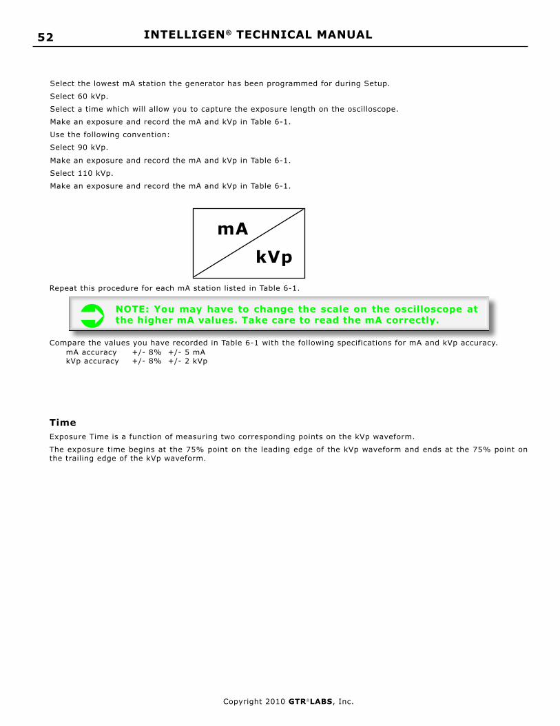
INTELLIGEN® TECHNICAL MANUAL 52
Copyright 2010 GTRLABS, Inc.
Select the lowest mA station the generator has been programmed for during Setup.
Select 60 kVp.
Select a time which will allow you to capture the exposure length on the oscilloscope.
Make an exposure and record the mA and kVp in Table 6-1.
Use the following convention:
Select 90 kVp.
Make an exposure and record the mA and kVp in Table 6-1.
Select 110 kVp.
Make an exposure and record the mA and kVp in Table 6-1.
mAkVp
Repeat this procedure for each mA station listed in Table 6-1.
NOTE: You may have to change the scale on the oscilloscope at the higher mA values. Take care to read the mA correctly.
Compare the values you have recorded in Table 6-1 with the following specifications for mA and kVp accuracy. mA accuracy +/- 8% +/- 5 mA kVp accuracy +/- 8% +/- 2 kVp
TimeExposure Time is a function of measuring two corresponding points on the kVp waveform.
The exposure time begins at the 75% point on the leading edge of the kVp waveform and ends at the 75% point on the trailing edge of the kVp waveform.

53INTELLIGEN® TECHNICAL MANUAL
Copyright 2010 GTRLABS, Inc.
Table 6-2 Time Measurements
emiTdeyalpsiD
emiTderusaeM
emiTdeyalpsiD
emiTderusaeM
200. 004.
500. 005.
800. 006.
010. 007.
510. 008.
020. 00.1
520. 05.1
530. 00.2
050. 05.2
570. 00.3
001. 05.3
521. 00.4
051. 05.4
002. 00.5
052. 00.6
003.
Select 70 kVp, 100 mA , and 2 milliseconds on the Time Display (.002).
Make an exposure and measure the length of the kVp waveform on the oscilloscope.
Record that value in the corresponding box in Table 6-2.
Advance to the next Time station and repeat the procedure.
Continue until you have entered a value for each Time Station in Table 6-2.
NOTE: As you advance in time you will have to change the time base on the oscilloscope to present the entire kVp waveform on the oscilloscope display.
Compare the values you have recorded in Table 6-2 with the following specification for Time accuracy.Time accuracy: 0.002 Sec. to 0.010 Sec. +/- 0.5 ms 0.015 Sec. to 0.035 Sec. +/- 1.5 ms 0.050 Sec. to 0.100 Sec +/- 3.0 ms 0.125 Sec. to 6.0 Sec. +/- 3%
ReportingReport any difficulties you encounter during Compliance Testing to the manufacturer: GTR® LABS, Inc. 510 Elk Street, Gassaway, WV, USA 26624. Telephone 304-364-2211

INTELLIGEN® TECHNICAL MANUAL 54
Copyright 2010 GTRLABS, Inc.
elosnoCyalpsiDpVk noitpircseD
yalpsiDoN rorrEUCGlanretnI
10E elbaCecafretnI
20E kcolretnIlamrehTebuT
yalpsiDoN rorrEsnoitacinummoC
30E tuoemiTykcuB
40E tuoemiTtsooBrotoR
50E PERPo/wtnerruCrotoR
60E tuoemiTtsooBtnemaliF
70E tnerruCLIFdaB
80E hgiHooTtnerruCLIF
90E )hgihootpVk(tluaFpVkedohtaC
01E )hgihootAm(tluaFAmedonA
11E )hgihootpVk(tluaFpVkedonA
21E )hgihootAm(tluaFAmedohtaC
31E tluaFCET
41E tluaF1#MPI
51E tluaF2#MPI
Chapter 7: Diagnostics
OverviewThe Self-Diagnostic System of the generator provides accurate, detailed information about the functions of the genera-tor and attached peripheral equipment.
This information is presented in the form of numerical Error Codes.
For the Operator and the Service Engineer, these Error Codes are presented on the kVp Display of the Operator’s Con-sole. A table in the Operator’s Manual as well as the Technical Manual lists the Error Codes which can be displayed and describes the possible cause of the fault and the action the Operator should take.
Refer to Table 7-1 for the Error Codes presented on the kVp Display on the Operator’s Console.
If any of the Error Codes listed in Table 7-1 are showing on the display, refer to the following information for possible causes and suggested corrective action.
kVp Display
Table 7-1a Error Codes
elosnoCyalpsiDpVk noitpircseD
61E tluaFataDnoitarbilaC/puteS
71E tluaFrotinoMegatloV
81E elosnoCotgnidnopsertonUPG
91E erusopxegnirudporDpVk
02E ybdnatSnisroticapacnoegatloV
13E %58revoUH%
NOTE: In this section on Error Codes the following abbreviation is used: OPC = kVp Display on the Operator’s Console

55INTELLIGEN® TECHNICAL MANUAL
Copyright 2010 GTRLABS, Inc.
Error Codes
Error Code: E01 Description: Interface Cable Error
System Indication:Displayed until corrective action taken
Possible Causes:Disconnected or defective Interface Cable (BBU/HVT)
Error Code: E02 Description: Tube Thermal Interlock
System Indication:Displayed until corrective action taken
Possible Causes:X-Ray Tube overheated
Corrective Action:
Wait until X-ray Tube Cools
Error Code: E03 Description: Bucky Timeout Error
System Indication:No Exposure
Possible Causes:No Buck Motion Signal
Corrective Action:Check Bucky Movement
Error Code: E04 Description: Rotor Boost Time-out Error
System Indication:Stops PREP sequence in progressDisconnects 220 VAC Switched on SPB
Possible Causes:No Rotor current during PREPOpen MAIN or Phase Rotor Wires
Corrective Action:Check Rotor Cable
Error Code: E05 Description: Rotor Current without PREP Error
System Indication:Disconnects 220 VAC Switched on SPB
Possible Causes:Short in Rotor Cable Rotor Relay stuck
Error Code: E06 Description: Filament Boost Time-out Error
System Indication:Stops PREP Sequence in progressDisconnects 220 VAC Switched on SPB
Possible Causes:Incorrect or missing Calibration numbers for se-lected mA
Corrective Action:Restore Filament CurrentCheck Calibration numbers. Recalibrate if neces-sary.
Error Code: E07 Description: No Filament Current
System Indication:Disconnects 220 VAC Switched on SPB
Possible Causes:Open Small or Large FilamentDefective TEC PCBDefective BBU PCB
Corrective Action:Check Filament Continuity in tube, Cathode Cable, Input / Output Filament TransformerReplace TEC PCBReplace BBU PCB
Error Code: E08 Description: Filament Current Too Low Error
System Indication:Stops PREP sequence in progressDisconnects 220 VAC Switched on SPB
Possible Causes:Calibration Off
Corrective Action:Recalibrate
Error Code: E09 Description: Cathode Fault (kVp Too High)
System Indication:Stop EXP in progressDisconnects 220 VAC Switched on SPB
Possible Causes:High Voltage Arc on Anode sideDefective X-Ray TubeDefective High Voltage CableFailure in HVT

INTELLIGEN® TECHNICAL MANUAL 56
Copyright 2010 GTRLABS, Inc.
Error Code: E10 Description: Anode Fault (mA Too High)
System Indication:Stop EXP in progressDisconnects 220 VAC Switched on SPB
Possible Causes:Filament Numbers Too High
Corrective Action:Lower Filament Numbers - Recalibrate
Error Code: E11 Description: Anode Fault (kVp Too High)
System Indication:Stop EXP in progressDisconnects 220 VAC Switched on SPBPossible Causes:High Voltage Arc on Cathode sideDefective X-Ray TubeDefective High Voltage CableFailure in HVT
Error Code: E12 Description: Cathode Fault (mA Too High) System Indication:
Stop EXP in progressDisconnects 220 VAC Switched on SPB
Possible Causes:High Voltage Arc on Anode sideDefective X-Ray TubeDefective High Voltage CableFailure in HVT
Error Code: E13 Description: TEC pcb Fault Error
System Indication:Disconnects 220 VAC Switched on SPB
Possible Causes:Loss of Switched 220 VAC From SPB PCBBlown Fuse F1Defective TEC PCB
Corrective Action:Replace Fuse F1Replace TEC PCB
Error Code: E14 Description: IPM Fault Error
System Indication:Stops EXP in progressDisconnects 220 VAC Switched on SPB
Possible Causes:AC Line weak or collapsed (below 187 VAC)Excessive current through IPMShorted IPM
Corrective Action:Check IPM for short circuitCall Factory
Error Code: E16 Description: Setup/Calibration Data Incorrect (Will not reset)
System Indication:Checked on Power Up Sequence onlyComplete lockup of Operator’s ConsoleNo “Watch Dog” indication
Possible Causes:Setup/Calibration Data Missing or corrupted Defective BBU pcb
Corrective Action:Follow detailed procedure listed belowIf the problem recurs, replace BBU pcb
NOTE: If you have th i s E r ro r Code showing on the Operator’s Console, t h e g e n e r a t o r is d isabled unt i l y o u p e r f o r m t h e f o l l o w i n g procedure. With this Error Code, the SERVICE switch on the BBU pcb will not function.
If Error Code E16 appears on Start Up;1. Turn off the generator2. Turn off the Wall Disconnect3. Press and hold the Service Push Button on the BBU pcb and turn on the Wall Disconnect4. Hold the Service Push Button for approximately 2 seconds then release.5. When the Blue Watch Dog LED goes out, turn on the generator.

57INTELLIGEN® TECHNICAL MANUAL
Copyright 2010 GTRLABS, Inc.
WARNING: At this point you will have returned all of the Setup Locations to their factory default settings including calibration. Do not attempt to make an exposure until you h a v e c o m p l e t e d the steps detailed in Chapter 4 and Chapter 5. Failure t o f o l l o w t h i s W A R N I N G m a y result in damage to the equipment and/or fai lure of the x-ray tube.
6. Press the Service Push Button on the BBU pcb. You will now be in the SERVICE Mode. All of the Setup Locations will be reset to Factory Default values. You must complete all of the steps in Chapter 4, Setup and calibrate the generator ac-cording to instructions in Chapter 5, Calibration.7. Exit the SERVICE Mode bypressing the Ser-vice Push Button on the BBU pcb. The generator should return to normal operation with no error codes displayed on the Operator’s Console.
Error Code: E17 Description: Buss Voltage Monitor Fault Error
System Indication:No Voltage on CAP Buss at the end of PREPDisconnects 220 VAC Switched on SPB
Possible Causes:Failure in Pre-Charge circuitFailure in Charge circuit
Corrective Action:Replace Charge ResistorReplace SPB PCB
Error Code: E19 Description: kVp Drop During Exposure
System Indication:If you monitor with an oscilliscope you will observe that the selected kVp is correct at the beginning of the exposure but drops several milliseconds into the exposure to 50 or less.
Possible Causes:High Impedence Short in X-Ray TubeCarbon Track in Cable Wells (Tube or Trans-former)Shorted IPMIPM Driver OptoCoupler Failure
Corrective Action:Look for bubbles in X-Ray Tube oilCheck Cable Wells (Tube and Transformer)Check IPMs (Remove output leads and check with ohmme ter from output terminal to each of the other two terminals).Replace IPM Driver
Error Code: E20 Description: Voltage on Capacitors in Stand By
System Indication:Prohibit Exposure Sequence
Possible Causes:Defective SPB pcb
Corrective Action:Replace SPB pcb
Error Code: E31 Description: % HU over 85%
System Indication:Prohibit Exposure Sequence
Possible Causes:X-Ray Tube Anode overheated
Corrective Action:Wait for X-Ray Tube Anode to Cool

INTELLIGEN® TECHNICAL MANUAL 58
Copyright 2010 GTRLABS, Inc.
Trouble-Shooting TipsThis section contains information to assist the service technician in trouble-shooting the generator.
The information presented is in order of descending importance. The most likely cause is first and the next likely cause is second, etc.
NOTE: The “Possible Causes” and “Corrective Actions” mentioned in this section DO NOT represent all of the factors that may apply to any given situation presented here.
System will not come on when On/Off pushbutton on the Operator’s Console is pressed.Possible Causes:
Incorrect or missing 208 VAC applied to GCUBlown Fuses 208 VAC on SPB pcbIncorrect or missing +12 VDC from SPB pcbBlown Fuse +12 VDC from SPB pcbIncorrect or missing +5 VDC Regulated from SPB pcbBlown Fuse + 5 VDC Regulated on SPB pcbInterconnecting cable missing or defective (GCU/Operator’s Console)Defective BBU pcbDefective Operator’s Console
IPM Fault occurs at higher KW settings only.Possible Causes:
Low 208 VAC Line Voltage AC Line Collapse during exposure

59INTELLIGEN® TECHNICAL MANUAL
Copyright 2010 GTRLABS, Inc.
Parts List
Figure S-1 Parts List
REBMUNTRAP NOITPIRCSED
1004 bcpCET
4304 bcprevirDMPI
2304 bcpBPS
bcpnoitpO
3304 bcpdraoBniarB
2006 KNATVH )04/03/02/01-V(
6406 elosnoCs'rotarepO
8406 )05-V(knaTVH
0168 rotsiseRegrahC-erP
2168 rotsiseRegrahcsiD
02501 )03/02/01-V(dfm0093
12501 )05/04-V(roticapaCdfm0074
05901 roticapaCxulF
15901 roticapaCrotoR
20011 MPI rebbunS
02021 )05/04-V(egdirBesahP3
52021 )03/02/01-V(egdirBesahP1
46181 )03/02/01-V(MPIA004
56181 )05/04-V(MPIA006
00632 )05/04-V(yaleRegrahCesahP3
01632 )03/02/01-V(yaleRegrahCesahP1
02113 esuFeniL
Acronyms
Figure S-2 Acronym Chart
BB draoBniarB gnissecorPPSD
UCG lortnoCrotareneGtinU
scinortceleehtgnisuohsissahcehTrotarenegehtrof
TVH egatloVhgiHremrofsnarT
tnemaliFdnaegatloVhgiHfoecruoSebutyar-xehtrofylppuS
MPI rewoPtnegilletnIeludoM
eludoMgnihctiwSycneuqerFhgiHbcprevirDMPIehtsedulcnihcihw
BPS rewoPmetsySdraoB
,CAV802rofecafretnisedivorProtoRdnaegrahcsiDdnaegrahC
CETcinoimrehTnoissimErellortnoC
ebutyar-xrofylppusfoecruoStnemalif


![· PDF file05/07/2017 · St Francis ChronicleJul 2017 Impact Studio C] PHOTOGRAPHY DESIGN & MARKETING Creative Intelligen Your independent community newspaper for St](https://static.fdocuments.us/doc/165x107/5aa7949b7f8b9ac5648c4e0b/francis-chroniclejul-2017-impact-studio-c-photography-design-marketing-creative.jpg)