INTELLICARB ICE COOLED DISPENSER - cornelius …guest/... · intellicarb ice cooled dispenser ......
42
INTELLICARB ICE COOLED DISPENSER INSTALLATION MANUAL Release Date: January 29, 2003 Publication Number: 630460204INS Revision Date: May 05, 2017 Revision: K Visit the Cornelius web site at www.cornelius.com for all your Literature needs.
Transcript of INTELLICARB ICE COOLED DISPENSER - cornelius …guest/... · intellicarb ice cooled dispenser ......
INTELLICARB ICE COOLED DISPENSER
INSTALLATION MANUAL
Release Date: January 29, 2003
Publication Number: 630460204INS
Revision Date: May 05, 2017
Revision: K
Visit the Cornelius web site at www.cornelius.com for all your Literature needs.

The products, technical information, and instructions contained in this manual are subject to change without notice.
These instructions are not intended to cover all details or variations of the equipment, nor to provide for every possi-
ble contingency in the installation, operation or maintenance of this equipment. This manual assumes that the per-
son(s) working on the equipment have been trained and are skilled in working with electrical, plumbing, pneumatic,
and mechanical equipment. It is assumed that appropriate safety precautions are taken and that all local safety and
construction requirements are being met, in addition to the information contained in this manual.
This Product is warranted only as provided in Cornelius’ Commercial Warrant applicable to this Product and is sub-
ject to all of the restrictions and limitations contained in the Commercial Warranty.
Cornelius will not be responsible for any repair, replacement or other service required by or loss or damage resulting
from any of the following occurrences, including but not limited to, (1) other than normal and proper use and normal
service conditions with respect to the Product, (2) improper voltage, (3) inadequate wiring, (4) abuse, (5) accident,
(6) alteration, (7) misuse, (8) neglect, (9) unauthorized repair or the failure to utilize suitably qualified and trained per-
sons to perform service and/or repair of the Product, (10) improper cleaning, (11) failure to follow installation, oper-
ating, cleaning or maintenance instructions, (12) use of “non-authorized” parts (i.e., parts that are not 100%
compatible with the Product) which use voids the entire warranty, (13) Product parts in contact with water or the
product dispensed which are adversely impacted by changes in liquid scale or chemical composition.
Contact Information:
To inquire about current revisions of this and other documentation or for assistance with any Cornelius product con-
tact:
www.cornelius.com
800-238-3600
Trademarks and Copyrights:
This document contains proprietary information and it may not be reproduced in any way without permission from
Cornelius.
Printed in U.S.A.

TABLE OF CONTENTSintellicarb ice cooled dispenser . . . . . . . . . . . . . . . . . . . . . . . . . . . . . . . . . . . . . . . . . . . . . . . . . . . . .i
Installation Manual . . . . . . . . . . . . . . . . . . . . . . . . . . . . . . . . . . . . . . . . . . . . . . . . . . . . . . . . . . . . . . i
table of contents . . . . . . . . . . . . . . . . . . . . . . . . . . . . . . . . . . . . . . . . . . . . . . . . . . . . . . . . . . . . . . . . . 1
Safety Instructions . . . . . . . . . . . . . . . . . . . . . . . . . . . . . . . . . . . . . . . . . . . . . . . . . . . . . . . . . . . . . . . 3
Read and Follow ALL Safety Instructions . . . . . . . . . . . . . . . . . . . . . . . . . . . . . . . . . . . . . . . . . . . . 3
Safety Overview . . . . . . . . . . . . . . . . . . . . . . . . . . . . . . . . . . . . . . . . . . . . . . . . . . . . . . . . . . . . 3
Recognition . . . . . . . . . . . . . . . . . . . . . . . . . . . . . . . . . . . . . . . . . . . . . . . . . . . . . . . . . . . . . . . . 3
Different Types of Alerts . . . . . . . . . . . . . . . . . . . . . . . . . . . . . . . . . . . . . . . . . . . . . . . . . . . . . . . . . 3
Safety Tips . . . . . . . . . . . . . . . . . . . . . . . . . . . . . . . . . . . . . . . . . . . . . . . . . . . . . . . . . . . . . . . . . . . 3
Qualified Service Personnel . . . . . . . . . . . . . . . . . . . . . . . . . . . . . . . . . . . . . . . . . . . . . . . . . . . . . . 3
Safety Precautions . . . . . . . . . . . . . . . . . . . . . . . . . . . . . . . . . . . . . . . . . . . . . . . . . . . . . . . . . . . . . 4
Shipping And Storage . . . . . . . . . . . . . . . . . . . . . . . . . . . . . . . . . . . . . . . . . . . . . . . . . . . . . . . . . . . 4
CO2 (Carbon Dioxide) Warning . . . . . . . . . . . . . . . . . . . . . . . . . . . . . . . . . . . . . . . . . . . . . . . . . . . 4
Mounting in or on a Counter . . . . . . . . . . . . . . . . . . . . . . . . . . . . . . . . . . . . . . . . . . . . . . . . . . . . . . 4
System Overview . . . . . . . . . . . . . . . . . . . . . . . . . . . . . . . . . . . . . . . . . . . . . . . . . . . . . . . . . . . . . . . . 5
Drop-In Product Overview . . . . . . . . . . . . . . . . . . . . . . . . . . . . . . . . . . . . . . . . . . . . . . . . . . . . . . . . 5
Specifications . . . . . . . . . . . . . . . . . . . . . . . . . . . . . . . . . . . . . . . . . . . . . . . . . . . . . . . . . . . . . . . . . 6
Drop-In Dimensions (CB1522) . . . . . . . . . . . . . . . . . . . . . . . . . . . . . . . . . . . . . . . . . . . . . . . . . 6
Drop-In Dimensions (CB2323) . . . . . . . . . . . . . . . . . . . . . . . . . . . . . . . . . . . . . . . . . . . . . . . . . 6
Drop-In Accessories — Optional . . . . . . . . . . . . . . . . . . . . . . . . . . . . . . . . . . . . . . . . . . . . . . . . 6
Custom Compact Dimensions . . . . . . . . . . . . . . . . . . . . . . . . . . . . . . . . . . . . . . . . . . . . . . . . . . 6
Drop-in Dimensions (CB3023) . . . . . . . . . . . . . . . . . . . . . . . . . . . . . . . . . . . . . . . . . . . . . . . . . 6
Installation . . . . . . . . . . . . . . . . . . . . . . . . . . . . . . . . . . . . . . . . . . . . . . . . . . . . . . . . . . . . . . . . . . . . . . 7
Installation Requirements . . . . . . . . . . . . . . . . . . . . . . . . . . . . . . . . . . . . . . . . . . . . . . . . . . . . . . . . 7
Delivery Inspection and Unpacking . . . . . . . . . . . . . . . . . . . . . . . . . . . . . . . . . . . . . . . . . . . . . . . . . 8
Installation Procedure . . . . . . . . . . . . . . . . . . . . . . . . . . . . . . . . . . . . . . . . . . . . . . . . . . . . . . . . . . . 9
Back Room Package . . . . . . . . . . . . . . . . . . . . . . . . . . . . . . . . . . . . . . . . . . . . . . . . . . . . . . . . . 9
Tubing . . . . . . . . . . . . . . . . . . . . . . . . . . . . . . . . . . . . . . . . . . . . . . . . . . . . . . . . . . . . . . . . . 9
Water . . . . . . . . . . . . . . . . . . . . . . . . . . . . . . . . . . . . . . . . . . . . . . . . . . . . . . . . . . . . . . . . . . 9
Syrup . . . . . . . . . . . . . . . . . . . . . . . . . . . . . . . . . . . . . . . . . . . . . . . . . . . . . . . . . . . . . . . . . 11
High Pressure Cylinder CO2 . . . . . . . . . . . . . . . . . . . . . . . . . . . . . . . . . . . . . . . . . . . . . . . 11
Bulk CO2 Tank . . . . . . . . . . . . . . . . . . . . . . . . . . . . . . . . . . . . . . . . . . . . . . . . . . . . . . . . . 12
1522-2323-3023 Drop-In . . . . . . . . . . . . . . . . . . . . . . . . . . . . . . . . . . . . . . . . . . . . . . . . . . . . . . . . 12
Conversion Instructions for Valves Connected into Manifold . . . . . . . . . . . . . . . . . . . . . . . . . 12
Conversion Instructions for 1522 Valve #1 from Carb to Non/Carb . . . . . . . . . . . . . . . . . . . . 13
Drop-In Installation . . . . . . . . . . . . . . . . . . . . . . . . . . . . . . . . . . . . . . . . . . . . . . . . . . . . . . . . . 13
CLEANING AND MAINTENANCE INSTRUCTIONS . . . . . . . . . . . . . . . . . . . . . . . . . . . . . . . . . . . . 16
Daily Cleaning: . . . . . . . . . . . . . . . . . . . . . . . . . . . . . . . . . . . . . . . . . . . . . . . . . . . . . . . . . . . . . . . 16
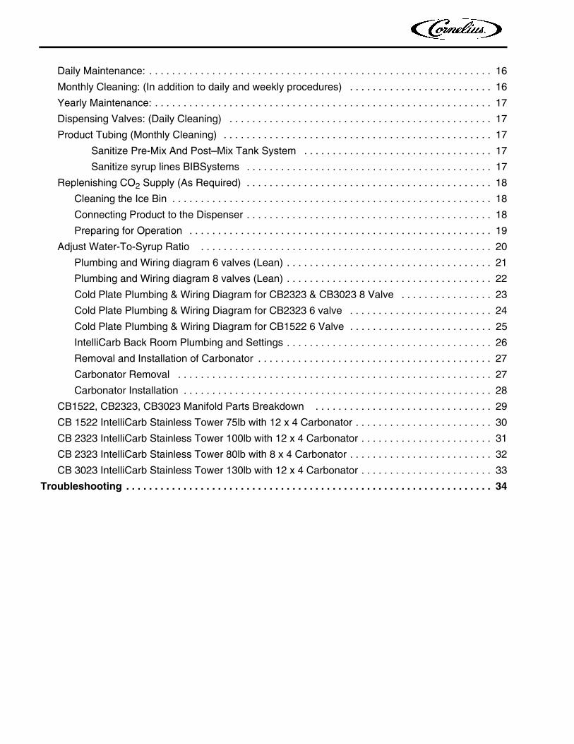
Daily Maintenance: . . . . . . . . . . . . . . . . . . . . . . . . . . . . . . . . . . . . . . . . . . . . . . . . . . . . . . . . . . . . 16
Monthly Cleaning: (In addition to daily and weekly procedures) . . . . . . . . . . . . . . . . . . . . . . . . . 16
Yearly Maintenance: . . . . . . . . . . . . . . . . . . . . . . . . . . . . . . . . . . . . . . . . . . . . . . . . . . . . . . . . . . . 17
Dispensing Valves: (Daily Cleaning) . . . . . . . . . . . . . . . . . . . . . . . . . . . . . . . . . . . . . . . . . . . . . . 17
Product Tubing (Monthly Cleaning) . . . . . . . . . . . . . . . . . . . . . . . . . . . . . . . . . . . . . . . . . . . . . . . 17
Sanitize Pre-Mix And Post–Mix Tank System . . . . . . . . . . . . . . . . . . . . . . . . . . . . . . . . . 17
Sanitize syrup lines BIBSystems . . . . . . . . . . . . . . . . . . . . . . . . . . . . . . . . . . . . . . . . . . . 17
Replenishing CO2 Supply (As Required) . . . . . . . . . . . . . . . . . . . . . . . . . . . . . . . . . . . . . . . . . . . 18
Cleaning the Ice Bin . . . . . . . . . . . . . . . . . . . . . . . . . . . . . . . . . . . . . . . . . . . . . . . . . . . . . . . . 18
Connecting Product to the Dispenser . . . . . . . . . . . . . . . . . . . . . . . . . . . . . . . . . . . . . . . . . . . 18
Preparing for Operation . . . . . . . . . . . . . . . . . . . . . . . . . . . . . . . . . . . . . . . . . . . . . . . . . . . . . 19
Adjust Water-To-Syrup Ratio . . . . . . . . . . . . . . . . . . . . . . . . . . . . . . . . . . . . . . . . . . . . . . . . . . . 20
Plumbing and Wiring diagram 6 valves (Lean) . . . . . . . . . . . . . . . . . . . . . . . . . . . . . . . . . . . . 21
Plumbing and Wiring diagram 8 valves (Lean) . . . . . . . . . . . . . . . . . . . . . . . . . . . . . . . . . . . . 22
Cold Plate Plumbing & Wiring Diagram for CB2323 & CB3023 8 Valve . . . . . . . . . . . . . . . . 23
Cold Plate Plumbing & Wiring Diagram for CB2323 6 valve . . . . . . . . . . . . . . . . . . . . . . . . . 24
Cold Plate Plumbing & Wiring Diagram for CB1522 6 Valve . . . . . . . . . . . . . . . . . . . . . . . . . 25
IntelliCarb Back Room Plumbing and Settings . . . . . . . . . . . . . . . . . . . . . . . . . . . . . . . . . . . . 26
Removal and Installation of Carbonator . . . . . . . . . . . . . . . . . . . . . . . . . . . . . . . . . . . . . . . . . 27
Carbonator Removal . . . . . . . . . . . . . . . . . . . . . . . . . . . . . . . . . . . . . . . . . . . . . . . . . . . . . . . 27
Carbonator Installation . . . . . . . . . . . . . . . . . . . . . . . . . . . . . . . . . . . . . . . . . . . . . . . . . . . . . . 28
CB1522, CB2323, CB3023 Manifold Parts Breakdown . . . . . . . . . . . . . . . . . . . . . . . . . . . . . . . 29
CB 1522 IntelliCarb Stainless Tower 75lb with 12 x 4 Carbonator . . . . . . . . . . . . . . . . . . . . . . . . 30
CB 2323 IntelliCarb Stainless Tower 100lb with 12 x 4 Carbonator . . . . . . . . . . . . . . . . . . . . . . . 31
CB 2323 IntelliCarb Stainless Tower 80lb with 8 x 4 Carbonator . . . . . . . . . . . . . . . . . . . . . . . . . 32
CB 3023 IntelliCarb Stainless Tower 130lb with 12 x 4 Carbonator . . . . . . . . . . . . . . . . . . . . . . . 33
Troubleshooting . . . . . . . . . . . . . . . . . . . . . . . . . . . . . . . . . . . . . . . . . . . . . . . . . . . . . . . . . . . . . . . . 34
IntelliCarb Drop-In Ice Cooled Installation Guide
© 2003-2017, Cornelius Inc. - 3 - Publication Number: 630460204INS
SAFETY INSTRUCTIONS
READ AND FOLLOW ALL SAFETY INSTRUCTIONS
Safety Overview
• Read and follow ALL SAFETY INSTRUCTIONS in this manual and any warning/caution labels on the unit (decals, labels or
laminated cards).
• Read and understand ALL applicable OSHA (Occupational Safety and Health Administration) safety regulations before
operating this unit.
Recognition
DIFFERENT TYPES OF ALERTS
! DANGER:Indicates an immediate hazardous situation which if not avoided WILL result in serious injury, death or equipment
damage.
! WARNING:Indicates a potentially hazardous situation which, if not avoided, COULD result in serious injury, death, or equipment
damage.
CAUTION:!Indicates a potentially hazardous situation which, if not avoided, MAY result in minor or moderate injury or equipment
damage.
SAFETY TIPS
• Carefully read and follow all safety messages in this manual and safety signs on the unit.
• Keep safety signs in good condition and replace missing or damaged items.
• Learn how to operate the unit and how to use the controls properly.
• Do not let anyone operate the unit without proper training. This appliance is not intended for use by very young children or
infirm persons without supervision. Young children should be supervised to ensure that they do not play with the appliance.
• Keep your unit in proper working condition and do not allow unauthorized modifications to the unit.
QUALIFIED SERVICE PERSONNEL
! WARNING:Only trained and certified electrical, plumbing and refrigeration technicians should service this unit. ALL WIRING AND
PLUMBING MUST CONFORM TO NATIONAL AND LOCAL CODES. FAILURE TO COMPLY COULD RESULT IN
SERIOUS INJURY, DEATH OR EQUIPMENT DAMAGE.
Recognize Safety Alerts
This is the safety alert symbol. When you see it in this manual or on the unit, be alert to the potential of personal injury or damage to the unit.
!
IntelliCarb Drop-In Ice Cooled Installation Guide
Publication Number: 630460204INS - 4 - © 2003-2017, Cornelius Inc.
SAFETY PRECAUTIONS
This unit has been specifically designed to provide protection against personal injury. To ensure continued protection
observe the following:
! WARNING:Disconnect power to the unit before servicing following all lock out/tag out procedures established by the user. Verify
all of the power is off to the unit before any work is performed.
Failure to disconnect the power could result in serious injury, death or equipment damage.
CAUTION:!Always be sure to keep area around the unit clean and free of clutter. Failure to keep this area clean may result in
injury or equipment damage.
SHIPPING AND STORAGE
CAUTION:!Before shipping, storing, or relocating the unit, the unit must be sanitized and all sanitizing solution must be drained
from the system. A freezing ambient environment will cause residual sanitizing solution or water remaining inside the
unit to freeze resulting in damage to internal components.
CO2 (CARBON DIOXIDE) WARNING
! DANGER:CO2 displaces oxygen. Strict attention MUST be observed in the prevention of CO2 gas leaks in the entire CO2 and
soft drink system. If a CO2 gas leak is suspected, particularly in a small area, IMMEDIATELY ventilate the
contaminated area before attempting to repair the leak. Personnel exposed to high concentrations of CO2 gas
experience tremors which are followed rapidly by loss of consciousness and DEATH.
MOUNTING IN OR ON A COUNTER
! WARNING:When installing the unit in or on a counter top, the counter must be able to support a weight in excess of 1522-230
lbs. 2323-340lbs. 3023-390lbs. to insure adequate support for the unit. Failure to comply could result in
serious injury, death or equipment damage.
NOTE: Many units incorporate the use of additional equipment such as icemakers. When any addi-
tion equipment is used you must check with the equipment manufacturer to determine the addi-
tional weight the counter will need to support to ensure a safe installation.
IntelliCarb Drop-In Ice Cooled Installation Guide
© 2003-2017, Cornelius Inc. - 5 - Publication Number: 630460204INS
SYSTEM OVERVIEW
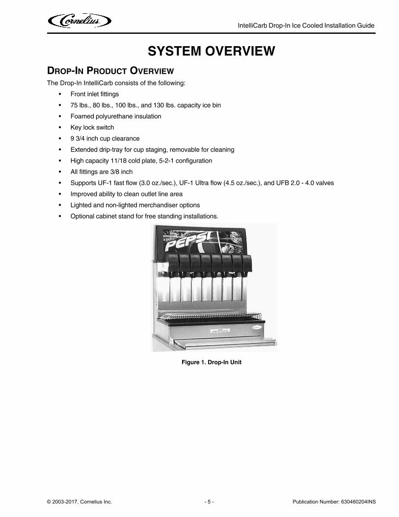
DROP-IN PRODUCT OVERVIEW
The Drop-In IntelliCarb consists of the following:
• Front inlet fittings
• 75 lbs., 80 lbs., 100 lbs., and 130 lbs. capacity ice bin
• Foamed polyurethane insulation
• Key lock switch
• 9 3/4 inch cup clearance
• Extended drip-tray for cup staging, removable for cleaning
• High capacity 11/18 cold plate, 5-2-1 configuration
• All fittings are 3/8 inch
• Supports UF-1 fast flow (3.0 oz./sec.), UF-1 Ultra flow (4.5 oz./sec.), and UFB 2.0 - 4.0 valves
• Improved ability to clean outlet line area
• Lighted and non-lighted merchandiser options
• Optional cabinet stand for free standing installations.
Figure 1. Drop-In Unit
IntelliCarb Drop-In Ice Cooled Installation Guide
Publication Number: 630460204INS - 6 - © 2003-2017, Cornelius Inc.
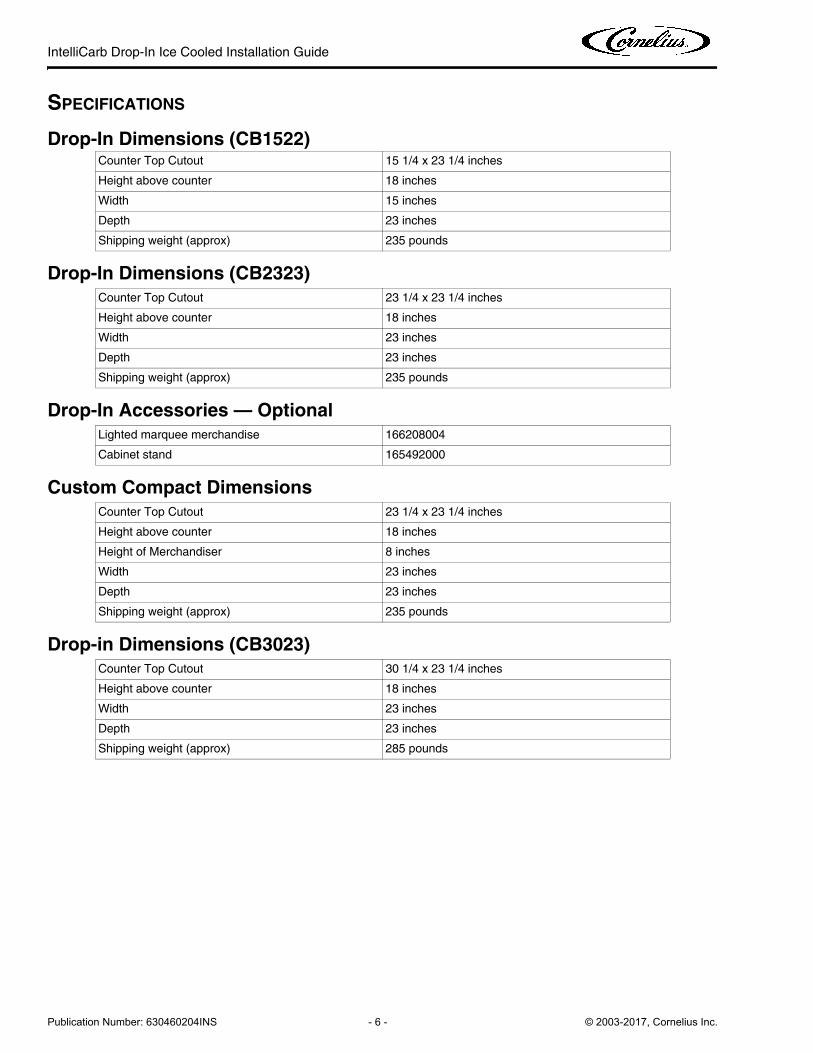
SPECIFICATIONS
Drop-In Dimensions (CB1522)
Drop-In Dimensions (CB2323)
Drop-In Accessories — Optional
Custom Compact Dimensions
Drop-in Dimensions (CB3023)
Counter Top Cutout 15 1/4 x 23 1/4 inches
Height above counter 18 inches
Width 15 inches
Depth 23 inches
Shipping weight (approx) 235 pounds
Counter Top Cutout 23 1/4 x 23 1/4 inches
Height above counter 18 inches
Width 23 inches
Depth 23 inches
Shipping weight (approx) 235 pounds
Lighted marquee merchandise 166208004
Cabinet stand 165492000
Counter Top Cutout 23 1/4 x 23 1/4 inches
Height above counter 18 inches
Height of Merchandiser 8 inches
Width 23 inches
Depth 23 inches
Shipping weight (approx) 235 pounds
Counter Top Cutout 30 1/4 x 23 1/4 inches
Height above counter 18 inches
Width 23 inches
Depth 23 inches
Shipping weight (approx) 285 pounds
IntelliCarb Drop-In Ice Cooled Installation Guide
© 2003-2017, Cornelius Inc. - 7 - Publication Number: 630460204INS
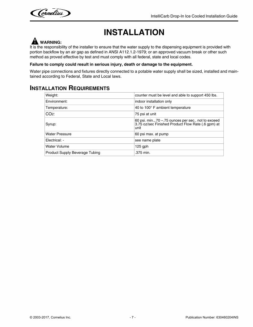
INSTALLATION! WARNING:
It is the responsibility of the installer to ensure that the water supply to the dispensing equipment is provided with
portion backflow by an air gap as defined in ANSI A112.1.2-1979; or an approved vacuum break or other such
method as proved effective by test and must comply with all federal, state and local codes.
Failure to comply could result in serious injury, death or damage to the equipment.
Water pipe connections and fixtures directly connected to a potable water supply shall be sized, installed and main-
tained according to Federal, State and Local laws.
INSTALLATION REQUIREMENTS
Weight: counter must be level and able to support 450 lbs.
Environment: indoor installation only
Temperature: 40 to 100° F ambient temperature
CO2: 75 psi at unit
Syrup:60 psi. min.,.70 –.75 ounces per sec., not to exceed 3.75 oz/sec Finished Product Flow Rate (.6 gpm) at unit
Water Pressure 60 psi max. at pump
Electrical: - see name plate
Water Volume 125 gph
Product Supply Beverage Tubing .375 min.
IntelliCarb Drop-In Ice Cooled Installation Guide
Publication Number: 630460204INS - 8 - © 2003-2017, Cornelius Inc.
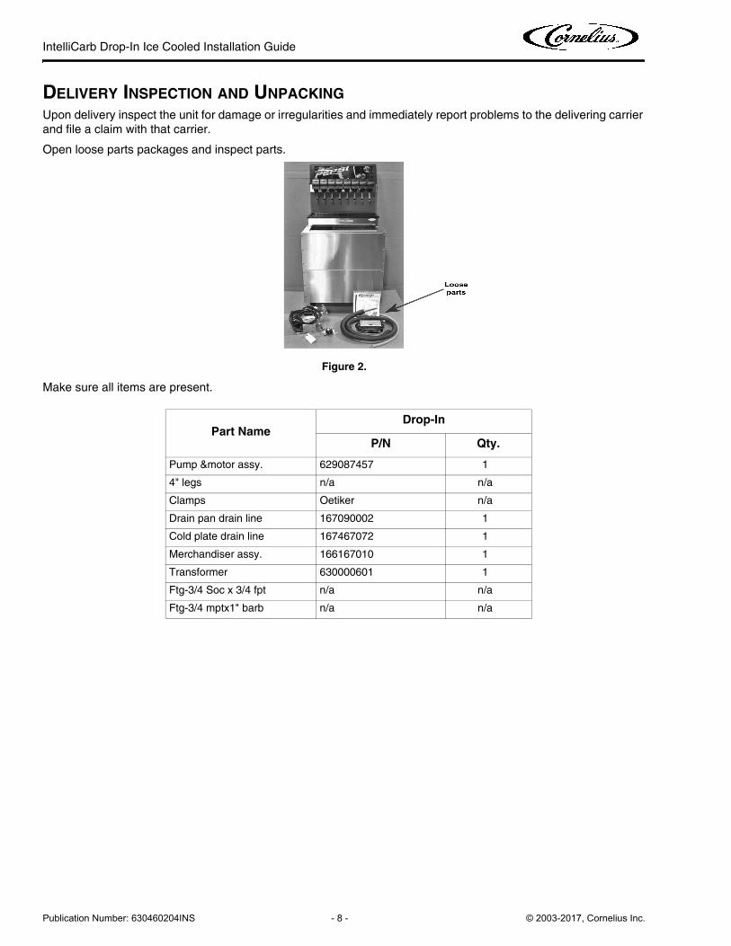
DELIVERY INSPECTION AND UNPACKING
Upon delivery inspect the unit for damage or irregularities and immediately report problems to the delivering carrier
and file a claim with that carrier.
Open loose parts packages and inspect parts.
Figure 2.
Make sure all items are present.
Part NameDrop-In
P/N Qty.
Pump &motor assy. 629087457 1
4" legs n/a n/a
Clamps Oetiker n/a
Drain pan drain line 167090002 1
Cold plate drain line 167467072 1
Merchandiser assy. 166167010 1
Transformer 630000601 1
Ftg-3/4 Soc x 3/4 fpt n/a n/a
Ftg-3/4 mptx1" barb n/a n/a

IntelliCarb Drop-In Ice Cooled Installation Guide
© 2003-2017, Cornelius Inc. - 9 - Publication Number: 630460204INS
INSTALLATION PROCEDURE
Back Room Package
Tubing
Run bundled tubing from back room to dispenser location.
NOTE: Tubing, hoses, and cabling can come from underneath or in back of the unit.
Water
1. Install water filter system between booster pump and water pressure regulator.
NOTE: Recommended shut off valve be installed on outlet side of filter system.
2. Run water line from source to inlet connection on booster pump.
3. Connect water line from booster pump outlet to water filter system inlet.
Figure 3. Pre filter (P/N 605620) Figure 4.Main Filter (P/N 605625ST) Figure 5. Polyphosphate feeder (Ice
maker)
IntelliCarb Drop-In Ice Cooled Installation Guide
Publication Number: 630460204INS - 10 - © 2003-2017, Cornelius Inc.
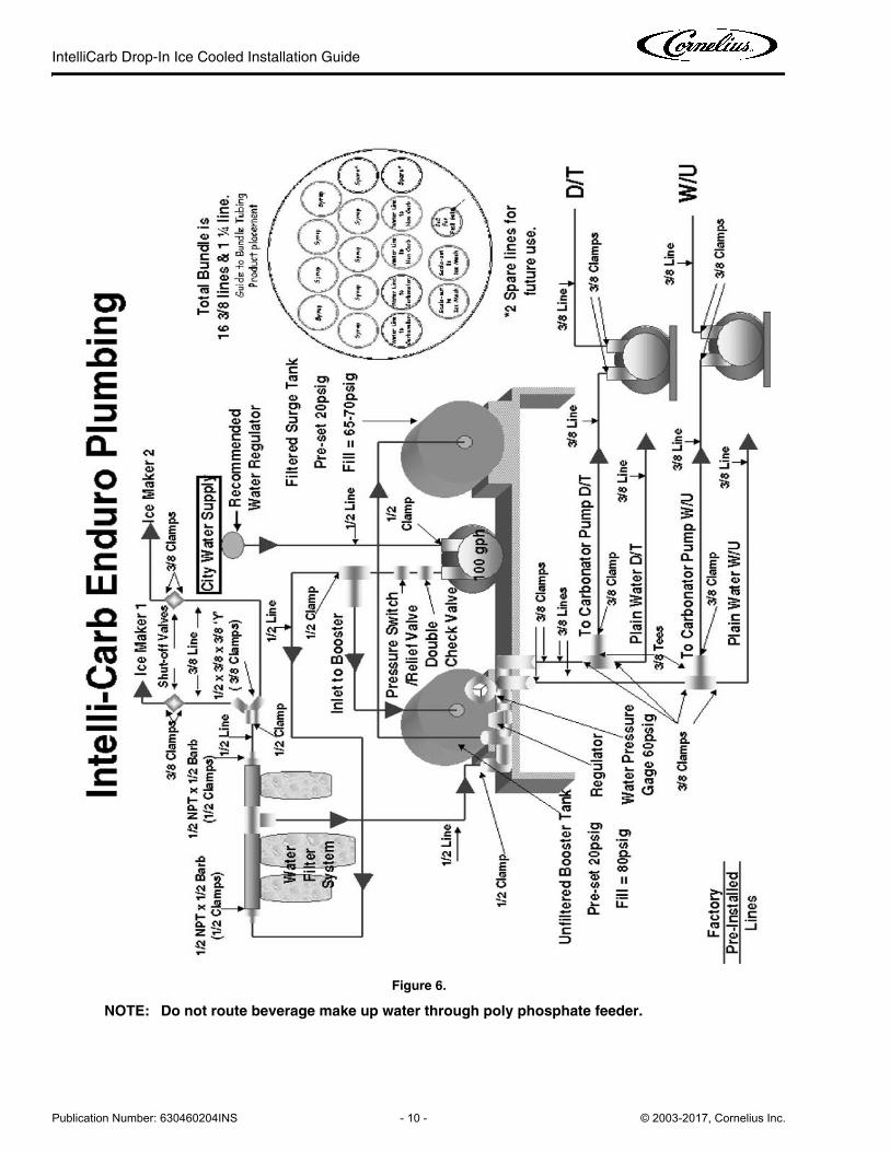
Figure 6.
NOTE: Do not route beverage make up water through poly phosphate feeder.
IntelliCarb Drop-In Ice Cooled Installation Guide
© 2003-2017, Cornelius Inc. - 11 - Publication Number: 630460204INS
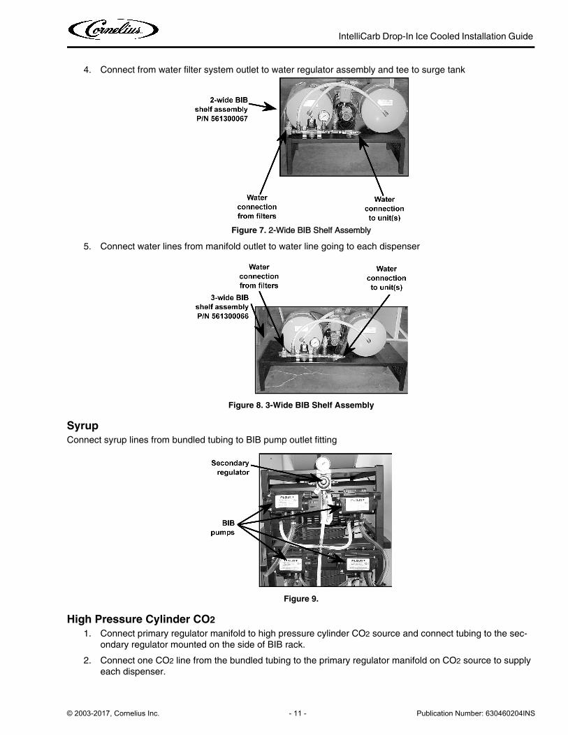
4. Connect from water filter system outlet to water regulator assembly and tee to surge tank
Figure 7. 2-Wide BIB Shelf Assembly
5. Connect water lines from manifold outlet to water line going to each dispenser
Figure 8. 3-Wide BIB Shelf Assembly
Syrup
Connect syrup lines from bundled tubing to BIB pump outlet fitting
Figure 9.
High Pressure Cylinder CO2
1. Connect primary regulator manifold to high pressure cylinder CO2 source and connect tubing to the sec-
ondary regulator mounted on the side of BIB rack.
2. Connect one CO2 line from the bundled tubing to the primary regulator manifold on CO2 source to supply
each dispenser.
IntelliCarb Drop-In Ice Cooled Installation Guide
Publication Number: 630460204INS - 12 - © 2003-2017, Cornelius Inc.
Bulk CO2 Tank
Connect bulk CO2 tank to the secondary regulator mounted on the side of BIB rack. Do not use primary reg-
ulator with bulk co2 tanks.
1522-2323-3023 DROP-IN
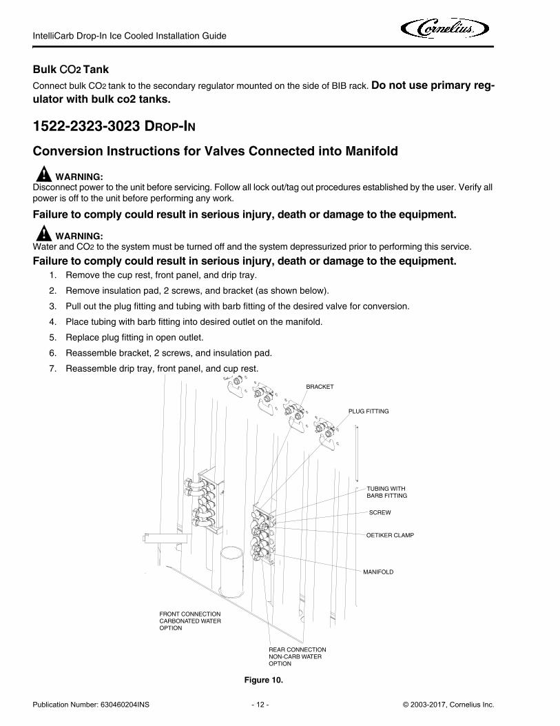
Conversion Instructions for Valves Connected into Manifold
! WARNING:Disconnect power to the unit before servicing. Follow all lock out/tag out procedures established by the user. Verify all
power is off to the unit before performing any work.
Failure to comply could result in serious injury, death or damage to the equipment.
! WARNING:Water and CO2 to the system must be turned off and the system depressurized prior to performing this service.
Failure to comply could result in serious injury, death or damage to the equipment.
1. Remove the cup rest, front panel, and drip tray.
2. Remove insulation pad, 2 screws, and bracket (as shown below).
3. Pull out the plug fitting and tubing with barb fitting of the desired valve for conversion.
4. Place tubing with barb fitting into desired outlet on the manifold.
5. Replace plug fitting in open outlet.
6. Reassemble bracket, 2 screws, and insulation pad.
7. Reassemble drip tray, front panel, and cup rest.
Figure 10.
PLUG FITTING
BRACKET
TUBING WITH BARB FITTING
SCREW
REAR CONNECTIONNON-CARB WATEROPTION
FRONT CONNECTIONCARBONATED WATER OPTION
MANIFOLD
OETIKER CLAMP

IntelliCarb Drop-In Ice Cooled Installation Guide
© 2003-2017, Cornelius Inc. - 13 - Publication Number: 630460204INS
Conversion Instructions for 1522 Valve #1 from Carb to Non/Carb
! WARNING:Disconnect power to the unit before servicing. Follow all lock out/tag out procedures established by the user. Verify all
power is off to the unit before performing any work.
Failure to comply could result in serious injury, death or damage to the equipment.
! WARNING:Water and CO2 to the system must be turned off and the system depressurized prior to performing this service.
Failure to comply could result in serious injury, death or damage to the equipment.
1. Remove the cup rest, front panel, and drip tray.
2. Remove insulation pad, 2 screws, and bracket (as shown above on page 12).
3. Pull out a plug fitting from the rear connection of the manifold.
4. Disconnect soda line from valve #1.
5. Assemble straight fitting and oetiker clamp to soda line from valve #1 (as shown on page 12).
6. Assemble soda line from valve #1 to manifold.
7. Assemble hose plug and clamp oetiker to soda line valve #1 (as shown on page 12).
8. Reassemble bracket, 2 screws, and insulation pad.
9. Reassemble drip tray, front panel, and cup rest.
Drop-In Installation
1. Install dispenser in counter following standard procedures.
2. Use the Template supplied to mark the location of the hole to be cut into the counter top. Cut the hole as
marked and remove the material.
3. Apply the double stick tape (if supplied with the loose shipped parts).
NOTE: To comply with the National Sanitation Foundation (NSF) requirements, the unit must be
sealed to the counter top.
4. Liberally apply a sealant, such as Dow Corning RTV 731 or equivalent, to the unit flange bottom surface.
5. Lower the unit into position to complete the seal of the rim to the counter top. Apply additional sealant
around the rim to ensure a complete seal.
NOTE: Do not move the unit after positioning or the seal will be broken.
6. Remove any excess sealant.
NOTE: For non-electrical valves, skip the next step.
7. Mount the Transformer power supply under the counter, in a position to allow access to the electrical outlet
and to allow the 24V power cord to reach the dispenser.
8. Install the drain hose to the ice bin drain fitting and route the drain hose to a permanent drain.
9. Mount secondary CO2 regulator, carbonator pump with motor, and valve transformer in a convenient loca-
tion, no more than 7 feet from the unit.
IntelliCarb Drop-In Ice Cooled Installation Guide
Publication Number: 630460204INS - 14 - © 2003-2017, Cornelius Inc.
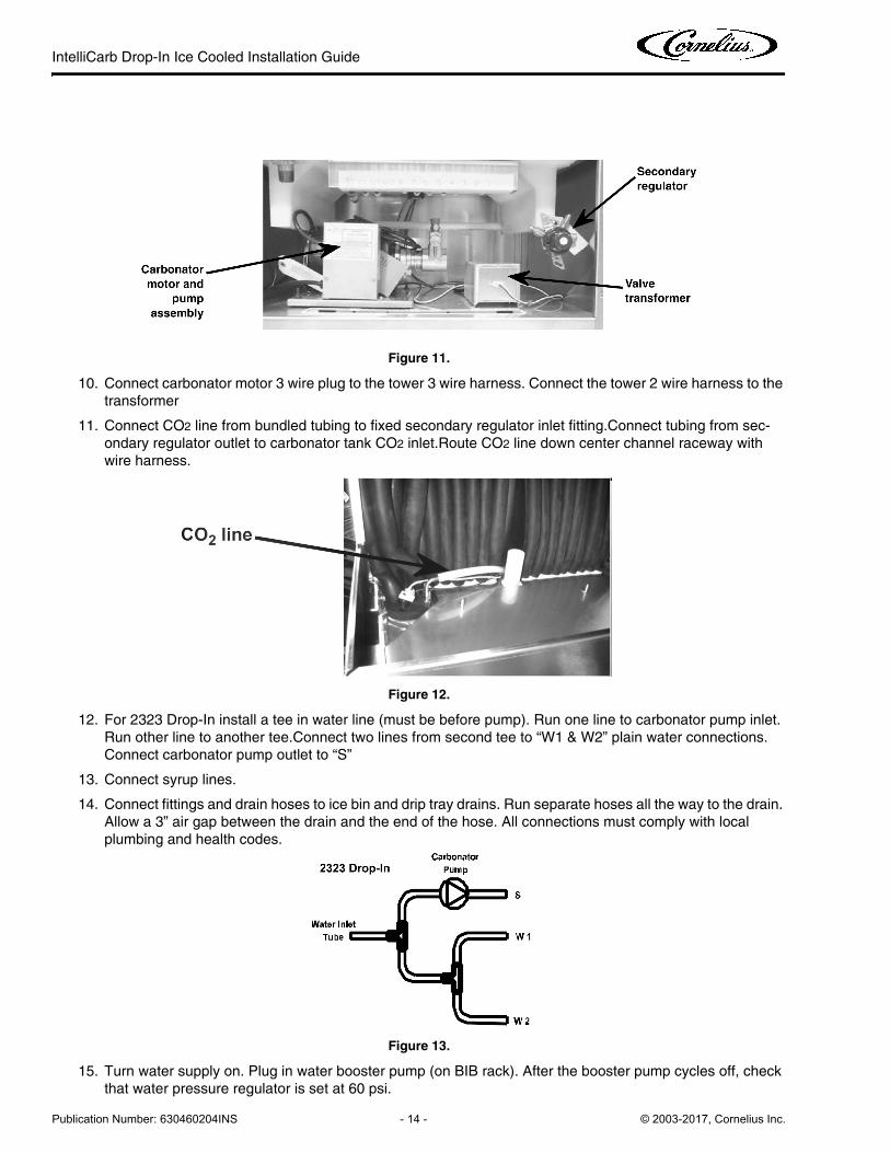
Figure 11.
10. Connect carbonator motor 3 wire plug to the tower 3 wire harness. Connect the tower 2 wire harness to the
transformer
11. Connect CO2 line from bundled tubing to fixed secondary regulator inlet fitting.Connect tubing from sec-
ondary regulator outlet to carbonator tank CO2 inlet.Route CO2 line down center channel raceway with
wire harness.
Figure 12.
12. For 2323 Drop-In install a tee in water line (must be before pump). Run one line to carbonator pump inlet.
Run other line to another tee.Connect two lines from second tee to “W1 & W2” plain water connections.
Connect carbonator pump outlet to “S”
13. Connect syrup lines.
14. Connect fittings and drain hoses to ice bin and drip tray drains. Run separate hoses all the way to the drain.
Allow a 3” air gap between the drain and the end of the hose. All connections must comply with local
plumbing and health codes.
Figure 13.
15. Turn water supply on. Plug in water booster pump (on BIB rack). After the booster pump cycles off, check
that water pressure regulator is set at 60 psi.
IntelliCarb Drop-In Ice Cooled Installation Guide
© 2003-2017, Cornelius Inc. - 15 - Publication Number: 630460204INS
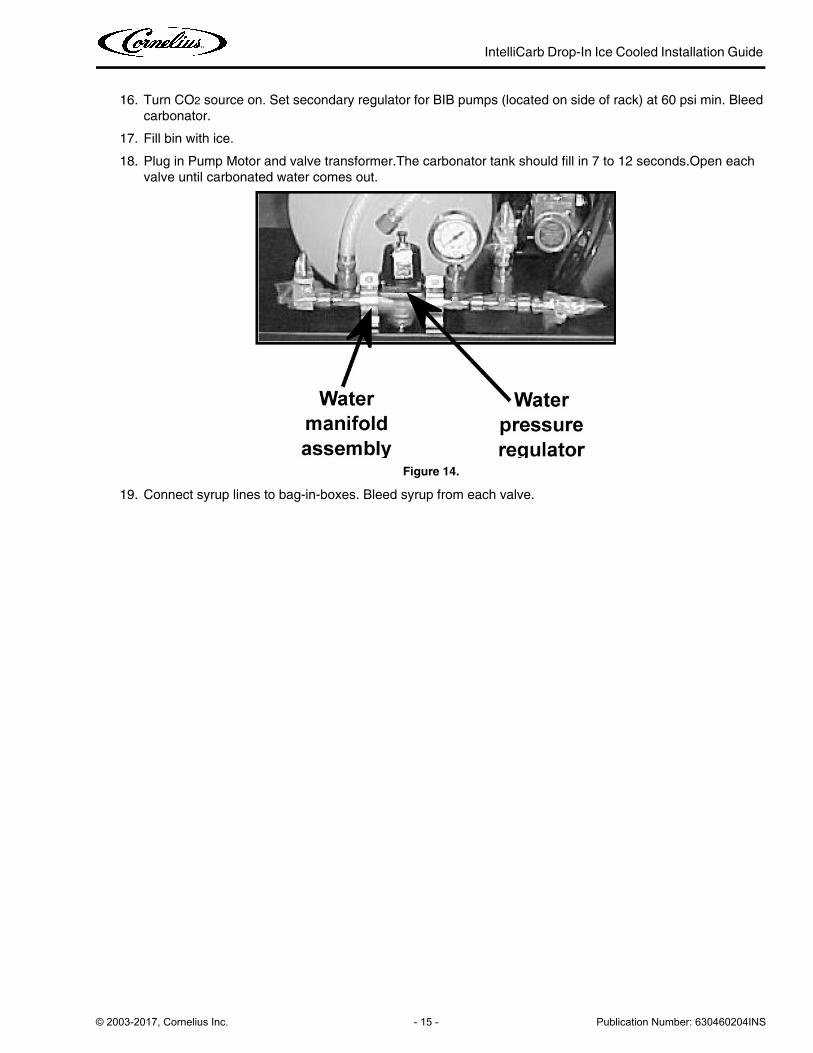
16. Turn CO2 source on. Set secondary regulator for BIB pumps (located on side of rack) at 60 psi min. Bleed
carbonator.
17. Fill bin with ice.
18. Plug in Pump Motor and valve transformer.The carbonator tank should fill in 7 to 12 seconds.Open each
valve until carbonated water comes out.
Figure 14.
19. Connect syrup lines to bag-in-boxes. Bleed syrup from each valve.
IntelliCarb Drop-In Ice Cooled Installation Guide
Publication Number: 630460204INS - 16 - © 2003-2017, Cornelius Inc.
CLEANING AND MAINTENANCE INSTRUCTIONS These instructions are used on all Cornelius ice drink dispensers. Some models may have additional cleaning
requirements. Those models will have addition procedures listed later in the manual.
! WARNING:Disconnect power to the unit before servicing. Follow all lock out/tag out procedures established by the user. Verify all
power is off to the unit before performing any work.
Failure to comply could result in serious injury, death or damage to the equipment.
CAUTION:!Do not use metal scrapers, sharp objects or abrasives on the ice storage hopper, top cover, agitator disc or exterior
surfaces as damage to the unit may result. Do not use solvents or other cleaning agents as they may attack the
material resulting in damage to the unit.
• Soap solution – Use a mixture of mild detergent and warm (100° F) potable water.
• Sanitizing Solution – Dissolve 2 packets (4 oz) of Stera Sheen Green Label into 2 gallons of warm (80 –
100° F) potable water to ensure 200 ppm of chlorine.
DAILY CLEANING:1. Remove cup rest from drip tray and clean with warm soapy water, rinse with clean water and allow to air
dry.
2. Wipe down the exterior of the unit with warm soapy water, rinse with clean water and allow to air dry.
3. Remove valve nozzles and diffusers and wash in warm soapy water, rinse in clean water and allow to air dry.
4. Clean the interior of the ice chute using the brush provided with the unit with warm soapy water, rinse with clean water and allow to air dry.
5. Spray the ice chute inside and out with sanitizer and allow to air dry.
6. Pour warm soapy water down the drains to keep them clean and flowing smoothly.
7. Spray the nozzles and diffusers inside and outside with approved sanitizing solution, reinstall them on the valves and allow to air dry.
8. Reinstall the cup rest into the drip tray.
9. Pour all remaining sanitizer solution down the drains to help keep the drain clear.
DAILY MAINTENANCE:1. Check the temperature, smell and taste of the product.
2. Check the water pressure coming to the unit using the pressure gauges on the back room package.
3. Check carbonation of the drink
4. Check level of CO2 supply to the system.
5. Check the date on all of the BIB’s (bags in boxes).
MONTHLY CLEANING: (IN ADDITION TO DAILY AND WEEKLY PROCEDURES)1. Flush and sanitize all syrup lines as well as all of the syrup connectors. (See the sanitize syrup lines
section shown later in this manual).
2. Remove ice from hopper and clean and sanitize the hopper. (See the Cleaning the interior surfaces section shown later in this manual).
IntelliCarb Drop-In Ice Cooled Installation Guide
© 2003-2017, Cornelius Inc. - 17 - Publication Number: 630460204INS
YEARLY MAINTENANCE:1. Have the water pump and check valve inspected and cleaned by a qualified service technician.
2. Have the CO2 gas check valve inspected and cleaned by a qualified service technician.
DISPENSING VALVES: (DAILY CLEANING) Refer to addendum supplied with the unit that is applicable to the manufacturer of the valves installed on the
unit.
PRODUCT TUBING (MONTHLY CLEANING)IMPORTANT:Only trained and qualified persons should perform these cleaning and sanitizing
procedures.
Sanitize Pre-Mix And Post–Mix Tank System
1. Remove all the quick disconnects from all the tanks. Fill a suitable pail or bucket with soap solution.
2. Submerge all disconnects (gas and liquid) in the soap solution and then clean them using a nylon bristle
brush. (Do not use a wire brush). Rinse with clean water.
3. Prepare sanitizing solution and using a mechanical spray bottle, spray the disconnects. Allow to air dry.
4. Using a clean, empty tank, prepare five (5) gallons of the sanitizing solution. Rinse the tank disconnects
with approximately 9 oz. of the sanitizing solution. Close the tank.
5. Prepare cleaning tank by filling clean five (5) gallon tank with a mixture of mild detergent and potable water
(120oF).
6. Connect a gas disconnect to the tank and then apply one of the product tubes to the cleaning tank. Oper-
ate the appropriate valve until liquid dispensed is free of any syrup.
7. Disconnect cleaning tank and hook up sanitizing tank to syrup line and CO2 system.
8. Energize beverage faucet until chlorine sanitizing solution is dispensed through the faucet. Flush at least
two (2) cups of liquid to ensure that the sanitizing solution has filled the entire length of the syrup tubing.
9. Allow sanitizer to remain in lines for fifteen (15) minutes.
10. Repeat the step above, applying a different product tube each time until all tubes are filled with the sanitiz-
ing solution.
11. Remove the nozzle and syrup diffuser and clean them in a mild soap solution.Rinse with clean water and reassemble the nozzle and syrup diffuser on the valve.
12. Rinse the parts in clean water, reassemble the valve and reconnect it to the dispenser.
13. Discard the tank of sanitizing solution and reconnect the product syrup tanks. Operate the valves until all
sanitizer has been flushed from the system and only product syrup is flowing.
Sanitize syrup lines BIBSystems
1. Remove all the quick disconnects from all the BIBcontainers.
2. Fill a suitable pail or bucket with soap solution.
3. Submerge all disconnects (gas and liquid) in the soap solution and then clean them using a nylon bristle
brush. (Do not use a wire brush). Rinse with clean water.
4. Using a plastic pail, prepare approximately five (5) gallons of sanitizing solution.
5. Rinse the BIBdisconnects in the sanitizing solution.
6. Sanitizing fittings must be attached to each BIBdisconnect. If these fittings are not available, the fittings
from empty BIBbags can be cut from the bags and used. These fittings open the disconnect so the sanitiz-
ing solution can be drawn through the disconnect.
IntelliCarb Drop-In Ice Cooled Installation Guide
Publication Number: 630460204INS - 18 - © 2003-2017, Cornelius Inc.
7. Place all the BIBdisconnects into the pail of sanitizing solution. Operate all the valves until the sanitizing
solution is flowing from the valve. Allow sanitizer to remain in lines for fifteen (15) minutes.
8. Remove the nozzle and syrup diffuser from each valve and clean them in a soap solution. Rinse with clean
water and reassemble the nozzle and syrup diffuser to the valve.
9. Remove the sanitizing fittings from the BIBdisconnects and connect the disconnects to the appropriate
BIBcontainer. Operate the valves until all sanitizer has been flushed from the system and syrup is flowing
freely.
REPLENISHING CO2 SUPPLY (AS REQUIRED)NOTE: When indicator on the 1800-psi gage is in the shaded (“change CO2 cylinder”) portion of
the dial, CO2 cylinder is almost empty and should be changed.
1. Fully close (clockwise) the CO2 cylinder valve.
2. Slowly loosen the CO2 regulator assembly coupling nut allowing CO2 pressure to escape, then remove the
regulator assembly from the empty CO2 cylinder.
3. Unfasten safety chain and remove the empty CO2 cylinder.
! WARNING:To avoid personnel injury and/or property damage, always secure the CO2 cylinder with a safety chain to prevent it
from falling over. Should the valve become accidentally damaged or broken off, a CO2 regulator can cause serious
personnel injury or death could occur.
4. Position the full CO2 cylinder and secure with a safety chain.
5. Make sure gasket is in place inside the CO2 regulator assembly coupling nut, then install the regulator
assembly on the CO2 cylinder.
6. Open (counterclockwise) the CO2 cylinder valve slightly to allow the lines to slowly fill with gas, then open
the valve fully to back-seat the valve (back-seating the valve prevents gas leakage around the valve shaft).
7. Check CO2 connections for leaks. Tighten any loose connections.
Cleaning the Ice Bin
1. Prepare a mild detergent soap solution in 100F potable water.
2. Using a nylon (not wire) bristle brush, clean the cold plate and the interior of the ice bin with the soap solu-
tion.
3. Rinse the cold plate and interior bin surfaces with clean potable water.
4. Using a mechanical spray bottle, prepare a sanitizing solution according to the manufacture’s directions
and spray the entire interior bin surfaces. Allow to air dry.
Connecting Product to the Dispenser
NOTE: All inlet connections are clearly marked with a label adjacent to the inlet connections.
NOTE: Always leak check all connections.
Post-Mix units must have syrup, carbonated water and plain water connected. The number of syrups will depend on
the number of valves on the dispenser. Refer to the plumbing diagram for details of the hookup.
Pre-Mix units must have a pre-mix supply connected to each inlet for each valve supplied. Refer to plumbing dia-
gram for details of the hook-up.
NOTE: A plumbing diagram when supplied with the unit, can be found in the dispensing tower.
IntelliCarb Drop-In Ice Cooled Installation Guide
© 2003-2017, Cornelius Inc. - 19 - Publication Number: 630460204INS
Preparing for Operation
On units Without Electrically Operated Valves, Skip Steps 1 and 2 Below
1. Plug transformer into electrical outlet. The 24V supply must be connected in the dispensing tower.
2. Turn the key-switch to the ON position. The ice-bin lid must be closed to allow the valves to operate.
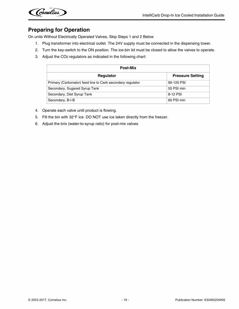
3. Adjust the CO2 regulators as indicated in the following chart:
4. Operate each valve until product is flowing.
5. Fill the bin with 32F ice. DO NOT use ice taken directly from the freezer.
6. Adjust the brix (water-to-syrup ratio) for post-mix valves.
Post-Mix
Regulator Pressure Setting
Primary (Carbonator) feed line to Carb secondary regulator 90-120 PSI
Secondary, Sugared Syrup Tank 55 PSI min.
Secondary, Diet Syrup Tank 8-12 PSI
Secondary, B-I-B 60 PSI min
IntelliCarb Drop-In Ice Cooled Installation Guide
Publication Number: 630460204INS - 20 - © 2003-2017, Cornelius Inc.
ADJUST WATER-TO-SYRUP RATIO
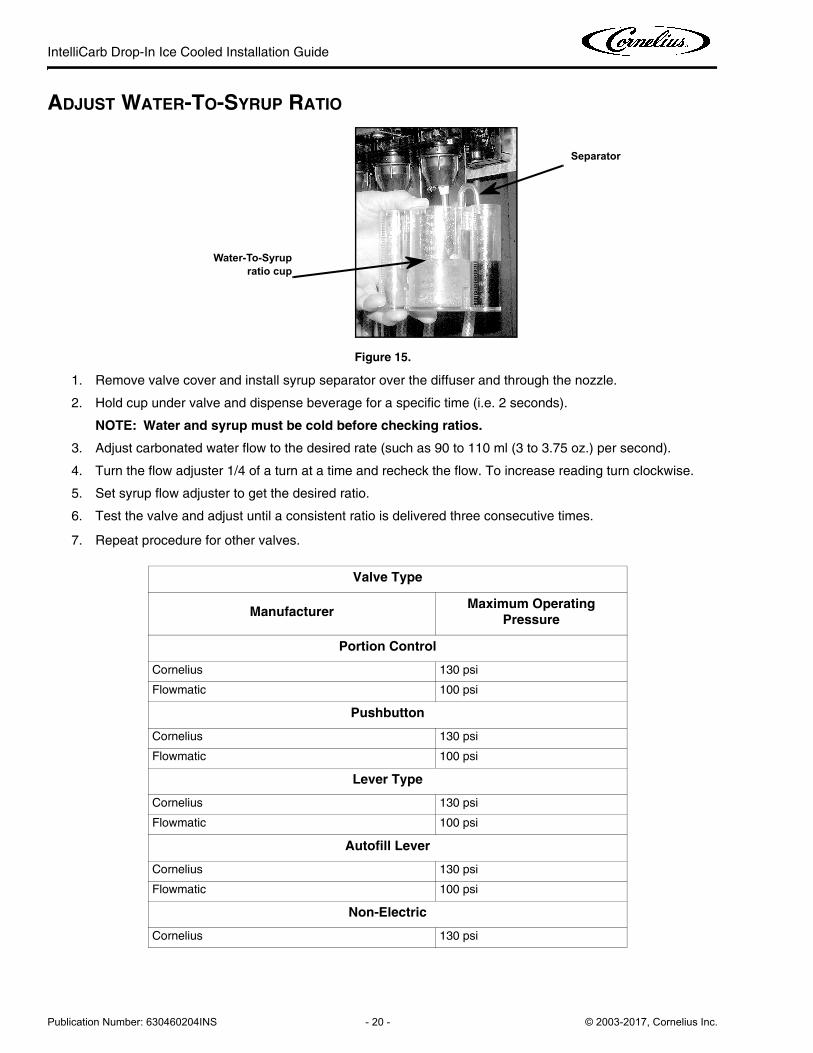
Figure 15.
1. Remove valve cover and install syrup separator over the diffuser and through the nozzle.
2. Hold cup under valve and dispense beverage for a specific time (i.e. 2 seconds).
NOTE: Water and syrup must be cold before checking ratios.
3. Adjust carbonated water flow to the desired rate (such as 90 to 110 ml (3 to 3.75 oz.) per second).
4. Turn the flow adjuster 1/4 of a turn at a time and recheck the flow. To increase reading turn clockwise.
5. Set syrup flow adjuster to get the desired ratio.
6. Test the valve and adjust until a consistent ratio is delivered three consecutive times.
7. Repeat procedure for other valves.
Valve Type
ManufacturerMaximum Operating
Pressure
Portion Control
Cornelius 130 psi
Flowmatic 100 psi
Pushbutton
Cornelius 130 psi
Flowmatic 100 psi
Lever Type
Cornelius 130 psi
Flowmatic 100 psi
Autofill Lever
Cornelius 130 psi
Flowmatic 100 psi
Non-Electric
Cornelius 130 psi
Separator
Water-To-Syrup ratio cup
W1
S1
4
CO
LDP
LATE
INLE
TS
2
21 1
32
3
4
65
45
6
DIS
PE
NS
ING
VA
LVE
S
PLU
MB
ING
DIA
GR
AM
(FR
ON
T V
IEW
)6
VA
LVE
UN
IT
SO
DA
OU
T
WA
TER
IN
CA
RB
ON
ATO
R
PR
OB
E
CO
-2VA
LVE
POST-CHILL
FRO
M M
OTO
R/P
UM
PP
LAIN
WA
TER
PRE-CHILL
GAS
WA
TER
SODA
MA
NIF
OLD
LE
FTW5
S4 S5
W4
S6
W6
W1
W1
SL
SR
MA
NIF
OLD
RIG
HT
M1
M3
M2
M4
M5
M6
SL SR
M4 M6M5
CONN
ECTI
ON
TO
LIG
HTED
CONT
INUO
USLY
HAVE
MER
CHAN
DISE
RG
RND
32
1
GRN
D
WH
OUT
LET
24 V
AC
VALV
E W
IRE
HARN
ESS
BK
BK
OPT
IONA
L
SWIT
CHKE
Y
OPT
IONA
L
BY K
EYSW
ITCH
MER
CHAN
DISE
RCO
NTRO
LLED
TO H
AVE
CONN
ECTI
ON
BK
BK
24 V
AC M
ERCH
.W
IRE
HARN
ESS
(SO
ME
UNIT
S)
LOCK
OUT
SWIT
CH
VALV
ECO
MNO
SUPP
LY
115
VAC
SUPP
LY
REM
OTE
MO
TOR/
PUM
P BO
X
POW
ER
WH
BK
GRN
D
12
3
24 V
ACPL
UGBK
WH
WIR
E
125 GPHBPUMP
CIRC
UIT
BOAR
D
WAT
ER IN
GRO
UND
WH
POW
ER11
5 VA
CW
ATER
OUT
- S
BK
WH
WH
BKW
H
BK
CARB
ONA
TOR
GRN
D
WIR
ING
DIA
GR
AM
VALV
ES24
VAC
REM
OTE
TRA
NSFO
RMER
BO
X
M1
W1
S1S2
M2
W2W3
S3
M3
35
6
IntelliCarb Drop-In Ice Cooled Installation Guide
© 2003-2017, Cornelius Inc. - 21 - Publication Number: 630460204INS
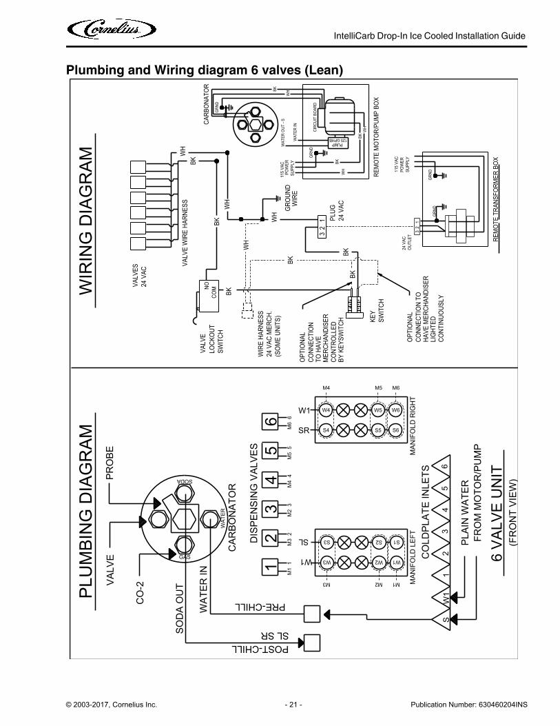
Plumbing and Wiring diagram 6 valves (Lean)

IntelliCarb Drop-In Ice Cooled Installation Guide
Publication Number: 630460204INS - 22 - © 2003-2017, Cornelius Inc.
Plumbing and Wiring diagram 8 valves (Lean)
CARB
ONA
TOR
BKBK
WH
WH
GRN
D
BK
CIRC
UIT
BOAR
D
WH
WH
GRN
D
GRO
UND
WIR
E
115
VAC
SUPP
LYPO
WER
WAT
ER IN
WAT
ER O
UT -
S
WH
PUMP125 GPHB
BK
BK
WH PO
WER
115
VAC
SUPP
LY
GRN
DG
RND
REM
OTE
MO
TOR/
PUM
P BO
X
NOVA
LVE
24 V
ACVA
LVES
SODAPR
OB
E
BK
WH
BK
WH
BK
SWIT
CH
WIR
E HA
RNES
S
TO H
AVE
(SO
ME
UNIT
S)
CONN
ECTI
ON
OPT
IONA
L
24 V
AC M
ERCH
.
COM
BKBK
24 V
AC
13
2
WH
BK
BK
OUT
LET
KEY
CONT
ROLL
EDBY
KEY
SWIT
CH
LIG
HTED
OPT
IONA
L
SWIT
CH
HAVE
MER
CHAN
DISE
RCO
NNEC
TIO
N TO
MER
CHAN
DISE
R3
21
87
6
WA
TER
53
48
M8
7 W8W7
M8M7
M6
6
W6
M6
M7
S8S7S6
AM
BIE
NT
SY
RU
PA
MB
IEN
TS
YR
UP
M5
W1
M4
3M
3
W1 W4
M4
SR
S4SL
S5
W5
M5
MA
NIF
OLD
RIG
HT
LOCK
OUT
WIR
ING
DIA
GR
AM
24 V
ACPL
UG
VALV
E W
IRE
HARN
ESS
BKW
H
WH
87
63
REM
OTE
TRA
NSFO
RMER
BO
X
BK
CONT
INUO
USLY
CO
-2VA
LVE GAS
WA
TER
IN
SO
DA
OU
T
21
PRE-CHILL
POST-CHILLSL SR
2M
21
M1
W1
M1
W2
M2
S3 S1S2
2W
11
S
CO
LDP
LATE
INLE
TS
DIS
PE
NS
ING
VA
LVE
S
PLU
MB
ING
DIA
GR
AM
(FR
ON
T V
IEW
)8
VA
LVE
UN
IT
CA
RB
ON
ATO
R
FRO
M M
OTO
R/P
UM
PP
LAIN
WA
TER
MA
NIF
OLD
LE
FT
W3
M3

IntelliCarb Drop-In Ice Cooled Installation Guide
© 2003-2017, Cornelius Inc. - 23 - Publication Number: 630460204INS
Cold Plate Plumbing & Wiring Diagram for CB2323 & CB3023 8 Valve
CO
NTI
NU
OU
SLY
BK
REM
OTE
TRA
NSF
ORM
ER B
OX
WH
WH
BK
VA
LVE
WIR
E H
ARN
ESS
PLU
G24
VA
C
LOC
KO
UT
12
3M
ERC
HA
ND
ISER
CO
NN
ECTI
ON
TO
HA
VE
MER
CH
AN
DIS
ER
SWIT
CH
OPT
ION
AL
LIG
HTE
D
BY
KEY
SWIT
CH
CO
NTR
OLL
ED
KEY
OU
TLET BK
BK
WH
23
1
24 V
AC
BKBK
COM
24 V
AC
MER
CH
.
OPT
ION
AL
CO
NN
ECTI
ON
(SO
ME
UN
ITS)
TO H
AV
E
WIR
E H
ARN
ESS
SWIT
CH
BK
WH
BK
WH
BK
VA
LVES
24 V
AC
VA
LVE
NO
REM
OTE
MO
TOR/
PUM
P B
OX
GRND
GRND
SUPP
LY
115
VA
CPO
WER
WH
BK
BK
125 GPHBPUMP
WH
WAT
ER O
UT - S
WAT
ER IN
POW
ERSU
PPLY
115
VA
C
WIR
EGR
OUND
GRND
WH
WH
CIRC
UIT B
OARD
BK
GRND
WH
WH
BKBK
CA
RBO
NA
TOR
MA
NIF
OLD
LEF
T
PLA
IN W
ATE
RFR
OM
MO
TOR/
PUM
P
CA
RBO
NA
TOR
8 V
ALV
E U
NIT
(FRO
NT
VIE
W)
PLU
MB
ING
DIA
GRA
M
DIS
PEN
SIN
G V
ALV
ES
CO
LDPL
ATE
INLE
TS
SW
11
2
M4
W4
M1
W1
M2
W2
M3
W3
SL SRPOST-CHILL
PRE-CHILL
12
M1
1
W1
M2
2
SOD
A O
UT
WA
TER
IN
GAS
VA
LVE
CO
-2
34
56
78
WIR
ING
DIA
GRA
M
M5
W5
S5
S4 S1S2S3
MA
NIF
OLD
RIG
HT
S8
W8
M8
S7S6
W7
M7
W6
M6
43
5
SL
M3
3M
44
M5
5
WA
TER
67
8M
7
SR
6M
6
W17M
88
PRO
BE
SODA
Figure 16.

IntelliCarb Drop-In Ice Cooled Installation Guide
Publication Number: 630460204INS - 24 - © 2003-2017, Cornelius Inc.
Cold Plate Plumbing & Wiring Diagram for CB2323 6 valve
CO
NTI
NU
OU
SLY
REM
OTE
TRA
NSF
ORM
ER B
OX
PLU
G24
VA
C
VA
LVE
WIR
E H
ARN
ESS
GRND
LOC
KOU
T
32
1M
ERC
HA
ND
ISER
HA
VE
MER
CH
AN
DIS
ERC
ON
NEC
TIO
N T
O
SWIT
CH
OPT
ION
AL
LIG
HTE
D
CO
NTR
OLL
EDBY
KEY
SWIT
CH KE
Y
OU
TLET
23
1
24 V
AC
BKBK
COM
24 V
AC
MER
CH
.(S
OM
E U
NIT
S)
CO
NN
ECTI
ON
TO H
AV
E
OPT
ION
AL
SWIT
CH
WIR
E H
ARN
ESS
BK
WH
BK
WH
BK
VA
LVE
NO24 V
AC
VA
LVES
REM
OTE
MO
TOR/
PUM
P BO
X
GRND
SUPP
LY
115
VA
CPO
WER
WH
BK
BK
PUMP125 GPHB
WH
WAT
ER O
UT - S
WAT
ER IN
115
VA
CPO
WER
SUPP
LYW
IREGR
OUND
GRND
WH
WH
CIRC
UIT B
OARD
BK
GRND
WH
BK
CA
RBO
NA
TOR
MA
NIF
OLD
LEF
T
PLA
IN W
ATE
RFR
OM
MO
TOR/
PUM
P
CA
RBO
NA
TOR
6 V
ALV
E U
NIT
(FRO
NT
VIE
W)
PLU
MBI
NG
DIA
GRA
M
DIS
PEN
SIN
G V
ALV
ES
2
CO
LDPL
ATE
INLE
TS
SW
11
M3
S3
W3 W2
M2
S2
M1
W1
S1
SL SRPOST-CHILL
PRE-CHILL
1
W1
SL
M1
1M
2
SOD
A O
UT
WA
TER
IN
GAS
VA
LVE
CO
-2
23
45
6
WIR
ING
DIA
GRA
M
M4
W4
S4
M5
W5
MA
NIF
OLD
RIG
HT
S6
W6
M6
S5
M5
34
M3
23
4M
4
WA
TER
56
SR
5M
66
W1
PRO
BE
SODA
Figure 17.
IntelliCarb Drop-In Ice Cooled Installation Guide
© 2003-2017, Cornelius Inc. - 25 - Publication Number: 630460204INS
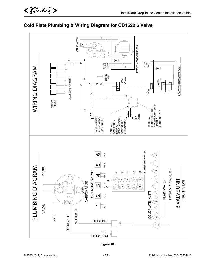
Cold Plate Plumbing & Wiring Diagram for CB1522 6 Valve
WS
4
CO
LDPL
ATE
INLE
TS
12
321
3
45
M66
56
DIS
PEN
SIN
G V
ALV
ES
PLU
MB
ING
DIA
GRA
M
(FRO
NT
VIE
W)
6 V
ALV
E U
NIT
WIR
ING
DIA
GRA
M
SOD
A O
UT
WA
TER
IN
CA
RBO
NA
TOR
PRO
BE
CO
-2
VA
LVE
POST-CHILL
FRO
M M
OTO
R/PU
MP
PLA
IN W
ATE
R
PRE-CHILL
SRS1
GAS
WA
TER
SODA
6H
AV
E M
ERC
HA
ND
ISER
REM
OTE
TRA
NSF
ORM
ER B
OX
CO
NTI
NU
OU
SLY
LIG
HTE
DGR
NDGR
ND
VA
LVE
WIR
E H
ARN
ESS
BK WH
1 PLU
G24
VA
C
CO
NN
ECTI
ON
SWIT
CH
CO
NN
ECTI
ON
TO
OPT
ION
AL
KEY
BY
KEY
SWIT
CH
MER
CH
AN
DIS
ERC
ON
TRO
LLED
TO H
AV
E
OU
TLET
24 V
AC
31
2
BKBK
23
24 V
AC
MER
CH
.W
IRE
HA
RNES
S
OPT
ION
AL
(SO
ME
UN
ITS)
BK
BK
WH
VA
LVES
24 V
AC
BK
GRND
125 GPHB
REM
OTE
MO
TOR/
PUM
P B
OX
SUPP
LYPO
WER
115
VA
C
PUMP
WH
BK
WH
BK
CIRC
UIT B
OARD
WAT
ER O
UT - S
2
WAT
ER IN
WIR
EGR
OUND
POW
ERSU
PPLY
115
VA
C
WH
WHBK
CA
RBO
NA
TOR
GRND
WH
FLEX
IBLE
MA
NIF
OLD
M2
W2
S2SR
W1
S3 S6
M3
W3
M6
W6
S11
M2
M3
23
M5
4M
45
W5
S5S4
W4
M5M4
Figure 18.
IntelliCarb Drop-In Ice Cooled Installation Guide
Publication Number: 630460204INS - 26 - © 2003-2017, Cornelius Inc.
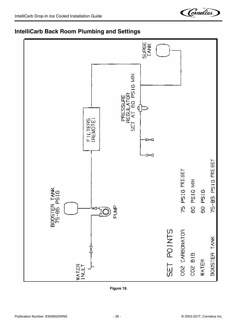
IntelliCarb Back Room Plumbing and Settings
Figure 19.
IntelliCarb Drop-In Ice Cooled Installation Guide
© 2003-2017, Cornelius Inc. - 27 - Publication Number: 630460204INS
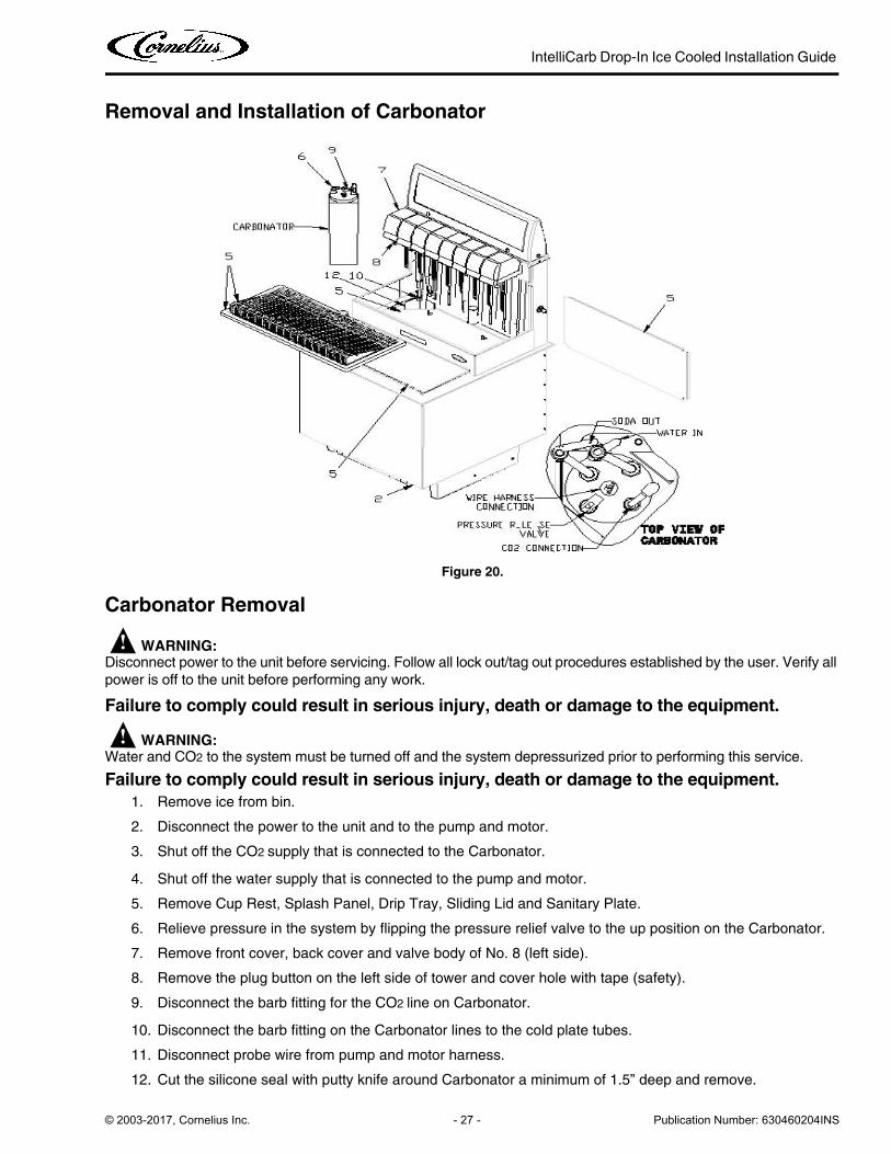
Removal and Installation of Carbonator
Figure 20.
Carbonator Removal
! WARNING:Disconnect power to the unit before servicing. Follow all lock out/tag out procedures established by the user. Verify all
power is off to the unit before performing any work.
Failure to comply could result in serious injury, death or damage to the equipment.
! WARNING:Water and CO2 to the system must be turned off and the system depressurized prior to performing this service.
Failure to comply could result in serious injury, death or damage to the equipment.
1. Remove ice from bin.
2. Disconnect the power to the unit and to the pump and motor.
3. Shut off the CO2 supply that is connected to the Carbonator.
4. Shut off the water supply that is connected to the pump and motor.
5. Remove Cup Rest, Splash Panel, Drip Tray, Sliding Lid and Sanitary Plate.
6. Relieve pressure in the system by flipping the pressure relief valve to the up position on the Carbonator.
7. Remove front cover, back cover and valve body of No. 8 (left side).
8. Remove the plug button on the left side of tower and cover hole with tape (safety).
9. Disconnect the barb fitting for the CO2 line on Carbonator.
10. Disconnect the barb fitting on the Carbonator lines to the cold plate tubes.
11. Disconnect probe wire from pump and motor harness.
12. Cut the silicone seal with putty knife around Carbonator a minimum of 1.5” deep and remove.
IntelliCarb Drop-In Ice Cooled Installation Guide
Publication Number: 630460204INS - 28 - © 2003-2017, Cornelius Inc.
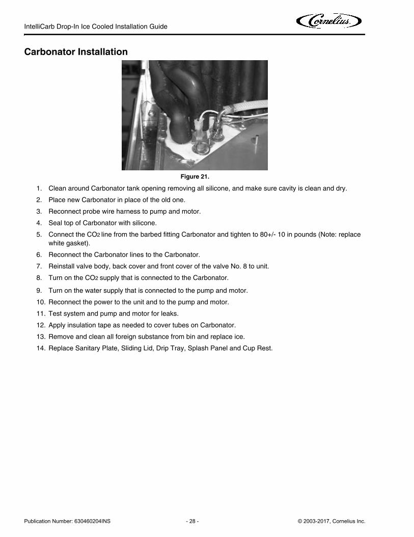
Carbonator Installation
Figure 21.
1. Clean around Carbonator tank opening removing all silicone, and make sure cavity is clean and dry.
2. Place new Carbonator in place of the old one.
3. Reconnect probe wire harness to pump and motor.
4. Seal top of Carbonator with silicone.
5. Connect the CO2 line from the barbed fitting Carbonator and tighten to 80+/- 10 in pounds (Note: replace
white gasket).
6. Reconnect the Carbonator lines to the Carbonator.
7. Reinstall valve body, back cover and front cover of the valve No. 8 to unit.
8. Turn on the CO2 supply that is connected to the Carbonator.
9. Turn on the water supply that is connected to the pump and motor.
10. Reconnect the power to the unit and to the pump and motor.
11. Test system and pump and motor for leaks.
12. Apply insulation tape as needed to cover tubes on Carbonator.
13. Remove and clean all foreign substance from bin and replace ice.
14. Replace Sanitary Plate, Sliding Lid, Drip Tray, Splash Panel and Cup Rest.
IntelliCarb Drop-In Ice Cooled Installation Guide
© 2003-2017, Cornelius Inc. - 29 - Publication Number: 630460204INS
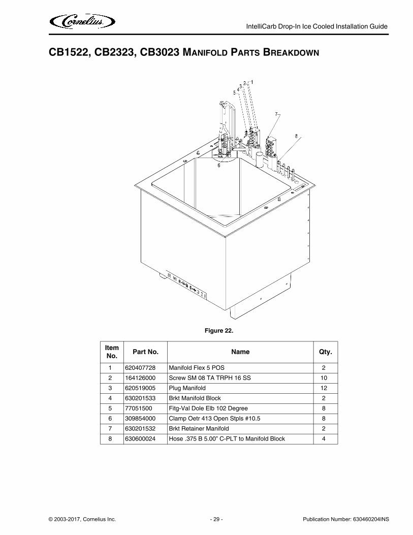
CB1522, CB2323, CB3023 MANIFOLD PARTS BREAKDOWN
Figure 22.
Item
No.Part No. Name Qty.
1 620407728 Manifold Flex 5 POS 2
2 164126000 Screw SM 08 TA TRPH 16 SS 10
3 620519005 Plug Manifold 12
4 630201533 Brkt Manifold Block 2
5 77051500 Fitg-Val Dole Elb 102 Degree 8
6 309854000 Clamp Oetr 413 Open Stpls #10.5 8
7 630201532 Brkt Retainer Manifold 2
8 630600024 Hose .375 B 5.00” C-PLT to Manifold Block 4
IntelliCarb Drop-In Ice Cooled Installation Guide
Publication Number: 630460204INS - 30 - © 2003-2017, Cornelius Inc.
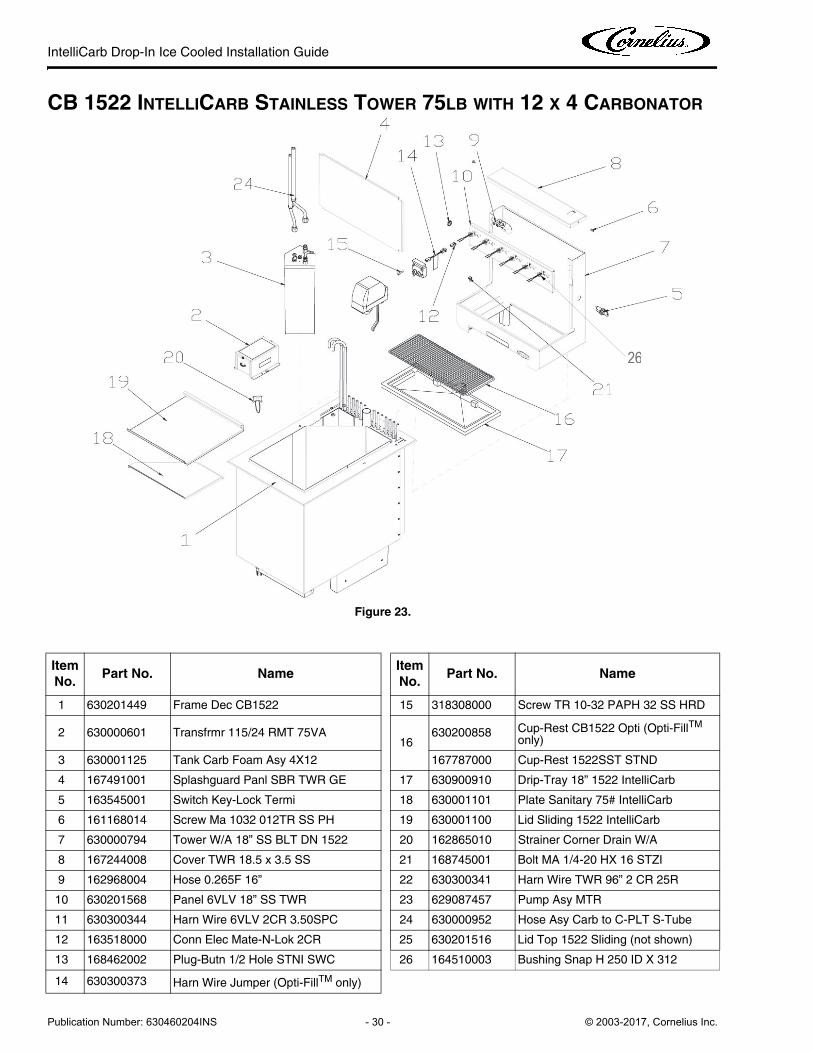
CB 1522 INTELLICARB STAINLESS TOWER 75LB WITH 12 X 4 CARBONATOR
Figure 23.
Item
No.Part No. Name
Item
No.Part No. Name
1 630201449 Frame Dec CB1522 15 318308000 Screw TR 10-32 PAPH 32 SS HRD
2 630000601 Transfrmr 115/24 RMT 75VA16
630200858 Cup-Rest CB1522 Opti (Opti-FillTM
only)
3 630001125 Tank Carb Foam Asy 4X12 167787000 Cup-Rest 1522SST STND
4 167491001 Splashguard Panl SBR TWR GE 17 630900910 Drip-Tray 18” 1522 IntelliCarb
5 163545001 Switch Key-Lock Termi 18 630001101 Plate Sanitary 75# IntelliCarb
6 161168014 Screw Ma 1032 012TR SS PH 19 630001100 Lid Sliding 1522 IntelliCarb
7 630000794 Tower W/A 18” SS BLT DN 1522 20 162865010 Strainer Corner Drain W/A
8 167244008 Cover TWR 18.5 x 3.5 SS 21 168745001 Bolt MA 1/4-20 HX 16 STZI
9 162968004 Hose 0.265F 16” 22 630300341 Harn Wire TWR 96” 2 CR 25R
10 630201568 Panel 6VLV 18” SS TWR 23 629087457 Pump Asy MTR
11 630300344 Harn Wire 6VLV 2CR 3.50SPC 24 630000952 Hose Asy Carb to C-PLT S-Tube
12 163518000 Conn Elec Mate-N-Lok 2CR 25 630201516 Lid Top 1522 Sliding (not shown)
13 168462002 Plug-Butn 1/2 Hole STNI SWC 26 164510003 Bushing Snap H 250 ID X 312
14 630300373 Harn Wire Jumper (Opti-FillTM only)
26
IntelliCarb Drop-In Ice Cooled Installation Guide
© 2003-2017, Cornelius Inc. - 31 - Publication Number: 630460204INS
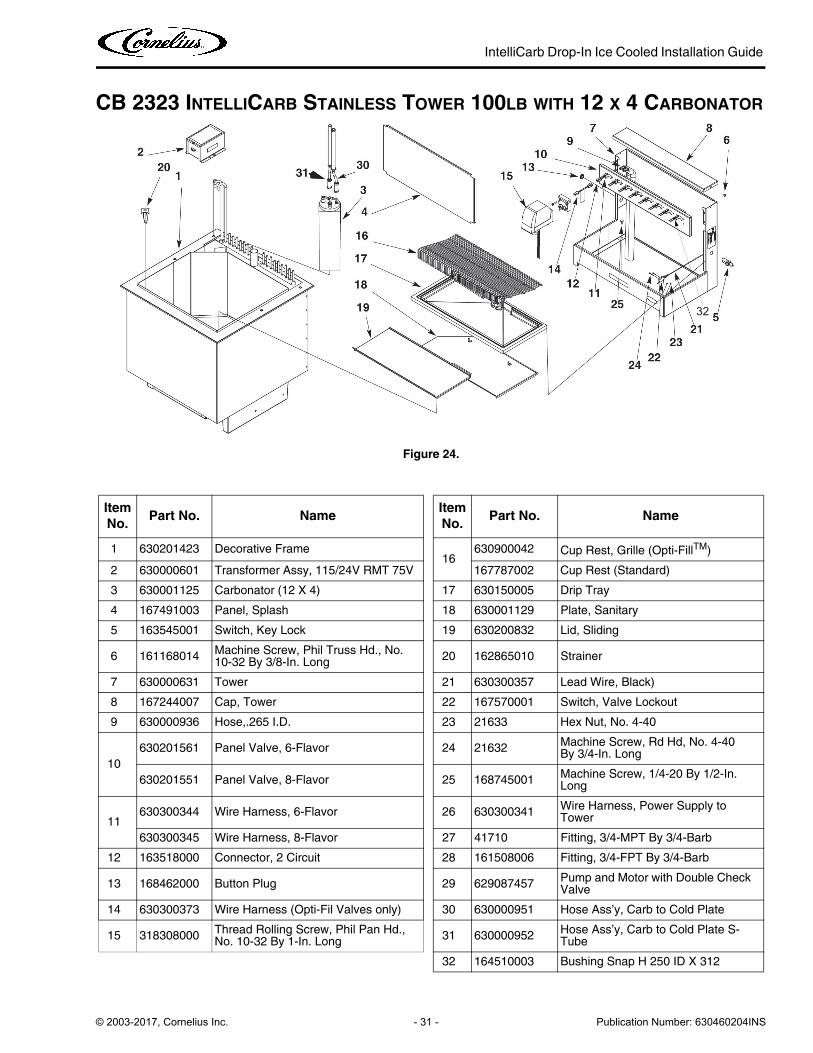
CB 2323 INTELLICARB STAINLESS TOWER 100LB WITH 12 X 4 CARBONATOR
Figure 24.
Item
No.Part No. Name
Item
No.Part No. Name
1 630201423 Decorative Frame16
630900042 Cup Rest, Grille (Opti-FillTM)
2 630000601 Transformer Assy, 115/24V RMT 75V 167787002 Cup Rest (Standard)
3 630001125 Carbonator (12 X 4) 17 630150005 Drip Tray
4 167491003 Panel, Splash 18 630001129 Plate, Sanitary
5 163545001 Switch, Key Lock 19 630200832 Lid, Sliding
6 161168014Machine Screw, Phil Truss Hd., No. 10-32 By 3/8-In. Long
20 162865010 Strainer
7 630000631 Tower 21 630300357 Lead Wire, Black)
8 167244007 Cap, Tower 22 167570001 Switch, Valve Lockout
9 630000936 Hose,.265 I.D. 23 21633 Hex Nut, No. 4-40
10
630201561 Panel Valve, 6-Flavor 24 21632Machine Screw, Rd Hd, No. 4-40 By 3/4-In. Long
630201551 Panel Valve, 8-Flavor 25 168745001Machine Screw, 1/4-20 By 1/2-In. Long
11630300344 Wire Harness, 6-Flavor 26 630300341
Wire Harness, Power Supply to Tower
630300345 Wire Harness, 8-Flavor 27 41710 Fitting, 3/4-MPT By 3/4-Barb
12 163518000 Connector, 2 Circuit 28 161508006 Fitting, 3/4-FPT By 3/4-Barb
13 168462000 Button Plug 29 629087457Pump and Motor with Double Check Valve
14 630300373 Wire Harness (Opti-Fil Valves only) 30 630000951 Hose Ass’y, Carb to Cold Plate
15 318308000Thread Rolling Screw, Phil Pan Hd., No. 10-32 By 1-In. Long
31 630000952Hose Ass’y, Carb to Cold Plate S-Tube
32 164510003 Bushing Snap H 250 ID X 312
32
IntelliCarb Drop-In Ice Cooled Installation Guide
Publication Number: 630460204INS - 32 - © 2003-2017, Cornelius Inc.
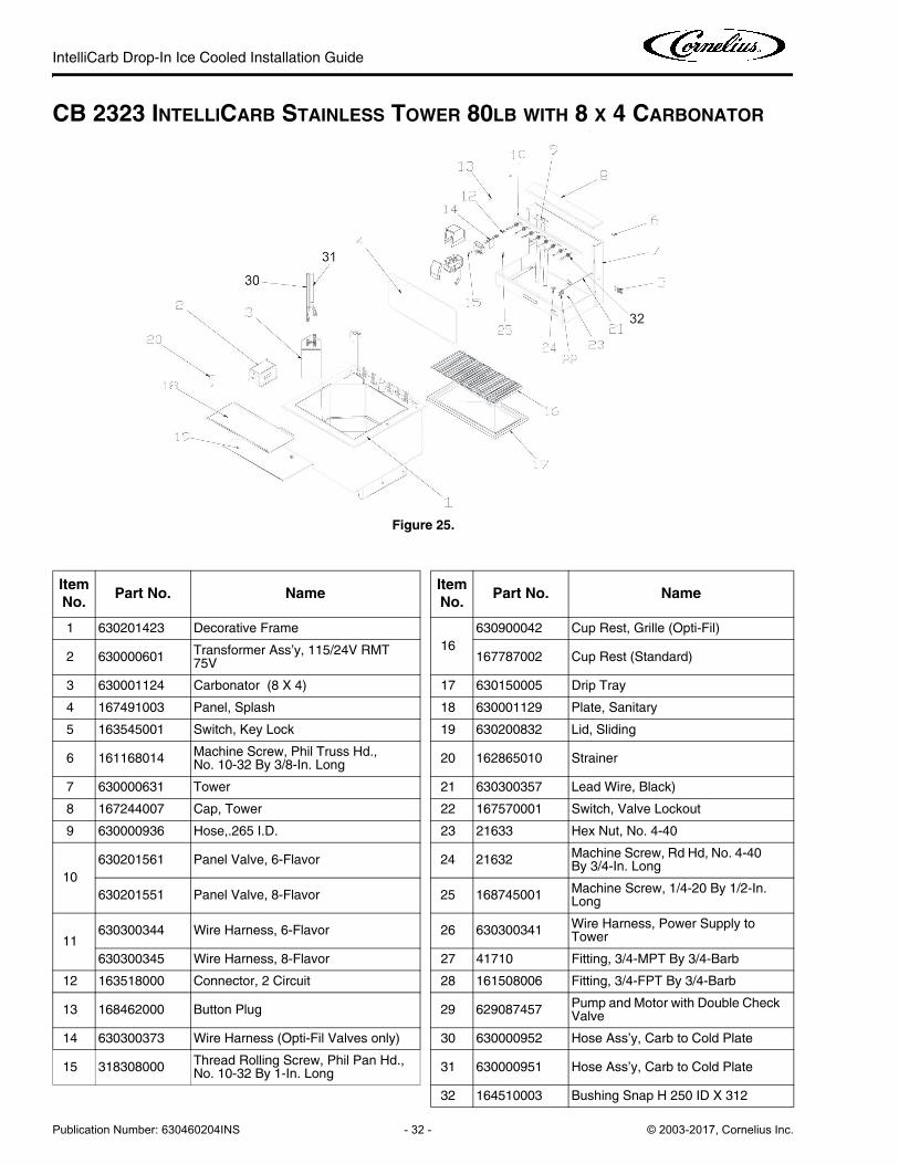
CB 2323 INTELLICARB STAINLESS TOWER 80LB WITH 8 X 4 CARBONATOR
Figure 25.
Item
No.Part No. Name
Item
No.Part No. Name
1 630201423 Decorative Frame
16
630900042 Cup Rest, Grille (Opti-Fil)
2 630000601Transformer Ass’y, 115/24V RMT 75V
167787002 Cup Rest (Standard)
3 630001124 Carbonator (8 X 4) 17 630150005 Drip Tray
4 167491003 Panel, Splash 18 630001129 Plate, Sanitary
5 163545001 Switch, Key Lock 19 630200832 Lid, Sliding
6 161168014Machine Screw, Phil Truss Hd., No. 10-32 By 3/8-In. Long
20 162865010 Strainer
7 630000631 Tower 21 630300357 Lead Wire, Black)
8 167244007 Cap, Tower 22 167570001 Switch, Valve Lockout
9 630000936 Hose,.265 I.D. 23 21633 Hex Nut, No. 4-40
10
630201561 Panel Valve, 6-Flavor 24 21632Machine Screw, Rd Hd, No. 4-40 By 3/4-In. Long
630201551 Panel Valve, 8-Flavor 25 168745001Machine Screw, 1/4-20 By 1/2-In. Long
11630300344 Wire Harness, 6-Flavor 26 630300341
Wire Harness, Power Supply to Tower
630300345 Wire Harness, 8-Flavor 27 41710 Fitting, 3/4-MPT By 3/4-Barb
12 163518000 Connector, 2 Circuit 28 161508006 Fitting, 3/4-FPT By 3/4-Barb
13 168462000 Button Plug 29 629087457Pump and Motor with Double Check Valve
14 630300373 Wire Harness (Opti-Fil Valves only) 30 630000952 Hose Ass’y, Carb to Cold Plate
15 318308000Thread Rolling Screw, Phil Pan Hd., No. 10-32 By 1-In. Long
31 630000951 Hose Ass’y, Carb to Cold Plate
32 164510003 Bushing Snap H 250 ID X 312
32
IntelliCarb Drop-In Ice Cooled Installation Guide
© 2003-2017, Cornelius Inc. - 33 - Publication Number: 630460204INS
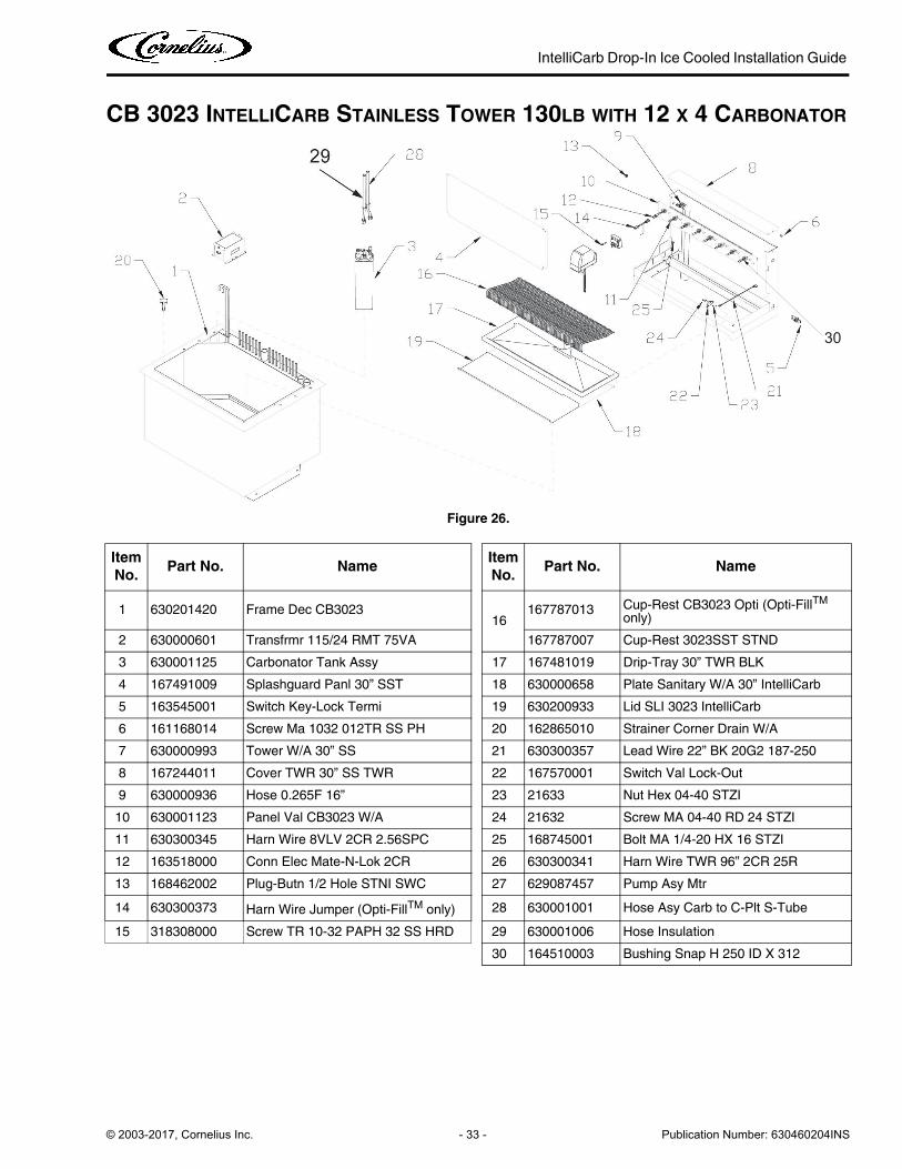
CB 3023 INTELLICARB STAINLESS TOWER 130LB WITH 12 X 4 CARBONATOR
Figure 26.
Item
No.Part No. Name
Item
No.Part No. Name
1 630201420 Frame Dec CB302316
167787013 Cup-Rest CB3023 Opti (Opti-FillTM only)
2 630000601 Transfrmr 115/24 RMT 75VA 167787007 Cup-Rest 3023SST STND
3 630001125 Carbonator Tank Assy 17 167481019 Drip-Tray 30” TWR BLK
4 167491009 Splashguard Panl 30” SST 18 630000658 Plate Sanitary W/A 30” IntelliCarb
5 163545001 Switch Key-Lock Termi 19 630200933 Lid SLI 3023 IntelliCarb
6 161168014 Screw Ma 1032 012TR SS PH 20 162865010 Strainer Corner Drain W/A
7 630000993 Tower W/A 30” SS 21 630300357 Lead Wire 22” BK 20G2 187-250
8 167244011 Cover TWR 30” SS TWR 22 167570001 Switch Val Lock-Out
9 630000936 Hose 0.265F 16” 23 21633 Nut Hex 04-40 STZI
10 630001123 Panel Val CB3023 W/A 24 21632 Screw MA 04-40 RD 24 STZI
11 630300345 Harn Wire 8VLV 2CR 2.56SPC 25 168745001 Bolt MA 1/4-20 HX 16 STZI
12 163518000 Conn Elec Mate-N-Lok 2CR 26 630300341 Harn Wire TWR 96” 2CR 25R
13 168462002 Plug-Butn 1/2 Hole STNI SWC 27 629087457 Pump Asy Mtr
14 630300373 Harn Wire Jumper (Opti-FillTM only) 28 630001001 Hose Asy Carb to C-Plt S-Tube
15 318308000 Screw TR 10-32 PAPH 32 SS HRD 29 630001006 Hose Insulation
30 164510003 Bushing Snap H 250 ID X 312
30
IntelliCarb Drop-In Ice Cooled Installation Guide
Publication Number: 630460204INS - 34 - © 2003-2017, Cornelius Inc.
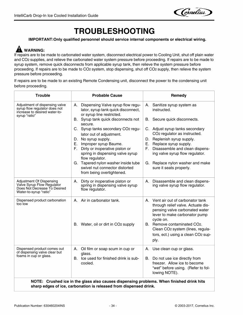
TROUBLESHOOTINGIMPORTANT:Only qualified personnel should service internal components or electrical wiring.
! WARNING:If repairs are to be made to carbonated water system, disconnect electrical power to Cooling Unit, shut off plain water
and CO2 supplies, and relieve the carbonated water system pressure before proceeding. If repairs are to be made to
syrup system, remove quick disconnects from applicable syrup tank, then relieve the system pressure before
proceeding. If repairs are to be made to CO2 system, stop dispensing, shut off CO2 supply, then relieve the system
pressure before proceeding.
If repairs are to be made to an existing Remote Condensing unit, disconnect the power to the condensing unit
before proceeding.
Trouble Probable Cause Remedy
Adjustment of dispensing valve syrup flow regulator does not increase to desired water-to-syrup “ratio”
A. Dispensing Valve syrup flow regu-
lator, syrup tank quick disconnect,
or syrup line restricted.
B. Syrup tank quick disconnects not
secure.
C. Syrup tanks secondary CO2 regu-
lator out of adjustment.
D. No syrup supply.
E. Improper syrup Baume.
F. Dirty or inoperative piston or
spring in dispensing valve syrup
flow regulator.
G. Tapered nylon washer inside tube
swivel nut connector distorted
from being overtightened.
A. Sanitize syrup system as
instructed.
B. Secure quick disconnects.
C. Adjust syrup tanks secondary
CO2 regulator as instructed.
D. Replenish syrup supply.
E. Replace syrup supply.
F. Disassemble and clean dispens-
ing valve syrup flow regulator.
G. Replace nylon washer and make
sure it seats properly.
Adjustment Of Dispensing Valve Syrup Flow Regulator Does Not Decrease To Desired Water-to-syrup “ratio”
A. Dirty or inoperative piston or spring in dispensing valve syrup flow regulator.
A. Disassemble and clean dispens-ing valve syrup flow regulator.
Dispensed product carbonation too low
A. Air in carbonator tank.
B. Water, oil or dirt in CO2 supply
A. Vent air out of carbonator tank
through relief valve. Actuate dis-
pensing valve carbonated water
lever to make carbonator pump
cycle on.
B. Remove contaminated CO2.
Clean CO2 system (lines, regula-
tors, ect.) using a clean CO2 sup-
ply.
Dispensed product comes out of dispensing valve clear but foams in cup or glass.
A. Oil film or soap scum in cup or
glass.
B. Ice used for finished drink is sub-
cooled.
A. Use clean cup or glass.
B. Do not use ice directly from
freezer. Allow ice to become
“wet” before using. (Refer to fol-
lowing NOTE).
NOTE: Crushed ice in the glass also causes dispensing problems. When finished drink hits
sharp edges of ice, carbonation is released from dispensed drink.
IntelliCarb Drop-In Ice Cooled Installation Guide
© 2003-2017, Cornelius Inc. - 35 - Publication Number: 630460204INS
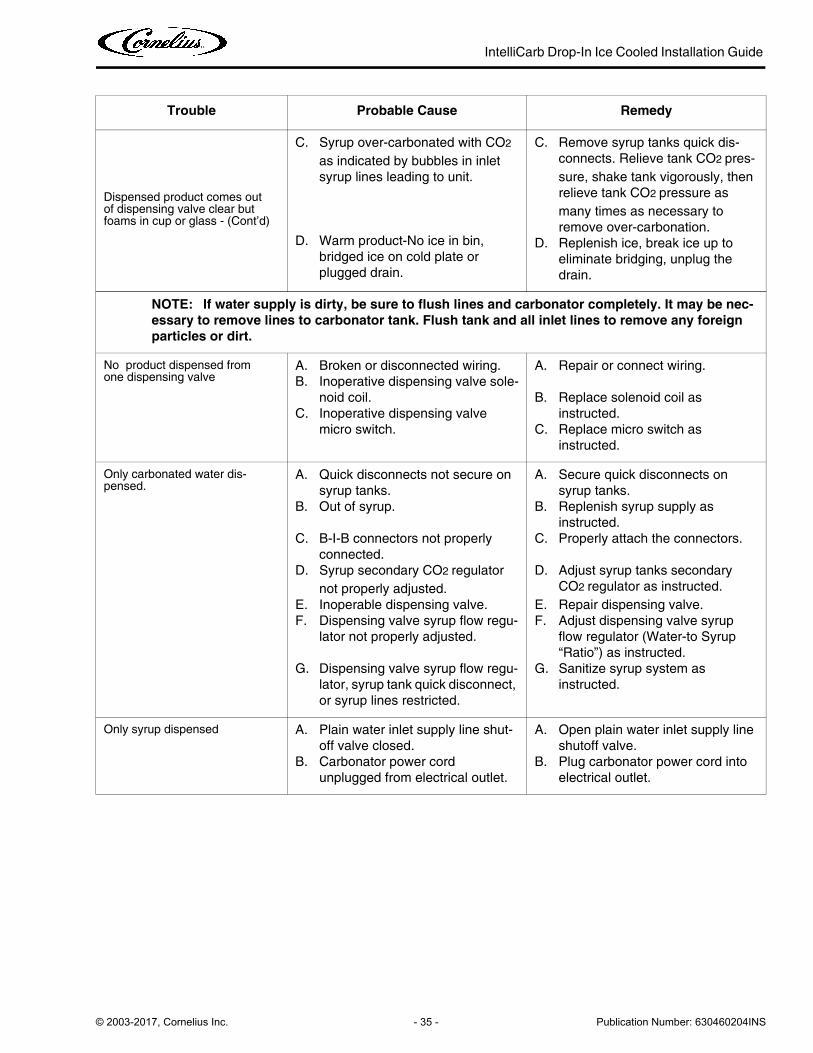
Dispensed product comes out of dispensing valve clear but foams in cup or glass - (Cont’d)
C. Syrup over-carbonated with CO2
as indicated by bubbles in inlet
syrup lines leading to unit.
D. Warm product-No ice in bin,
bridged ice on cold plate or
plugged drain.
C. Remove syrup tanks quick dis-
connects. Relieve tank CO2 pres-
sure, shake tank vigorously, then
relieve tank CO2 pressure as
many times as necessary to
remove over-carbonation.
D. Replenish ice, break ice up to
eliminate bridging, unplug the
drain.
NOTE: If water supply is dirty, be sure to flush lines and carbonator completely. It may be nec-
essary to remove lines to carbonator tank. Flush tank and all inlet lines to remove any foreign
particles or dirt.
No product dispensed from one dispensing valve
A. Broken or disconnected wiring.
B. Inoperative dispensing valve sole-
noid coil.
C. Inoperative dispensing valve
micro switch.
A. Repair or connect wiring.
B. Replace solenoid coil as
instructed.
C. Replace micro switch as
instructed.
Only carbonated water dis-pensed.
A. Quick disconnects not secure on
syrup tanks.
B. Out of syrup.
C. B-I-B connectors not properly
connected.
D. Syrup secondary CO2 regulator
not properly adjusted.
E. Inoperable dispensing valve.
F. Dispensing valve syrup flow regu-
lator not properly adjusted.
G. Dispensing valve syrup flow regu-
lator, syrup tank quick disconnect,
or syrup lines restricted.
A. Secure quick disconnects on
syrup tanks.
B. Replenish syrup supply as
instructed.
C. Properly attach the connectors.
D. Adjust syrup tanks secondary
CO2 regulator as instructed.
E. Repair dispensing valve.
F. Adjust dispensing valve syrup
flow regulator (Water-to Syrup
“Ratio”) as instructed.
G. Sanitize syrup system as
instructed.
Only syrup dispensed A. Plain water inlet supply line shut-
off valve closed.
B. Carbonator power cord
unplugged from electrical outlet.
A. Open plain water inlet supply line
shutoff valve.
B. Plug carbonator power cord into
electrical outlet.
Trouble Probable Cause Remedy
IntelliCarb Drop-In Ice Cooled Installation Guide
Publication Number: 630460204INS - 36 - © 2003-2017, Cornelius Inc.
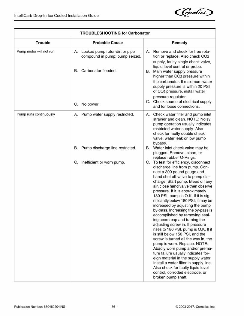
TROUBLESHOOTING for Carbonator
Trouble Probable Cause Remedy
Pump motor will not run A. Locked pump rotor-dirt or pipe
compound in pump; pump seized.
B. Carbonator flooded.
C. No power.
A. Remove and check for free rota-
tion or replace. Also check CO2
supply, faulty single check valve,
liquid level control or probe.
B. Main water supply pressure
higher than CO2 pressure within
the carbonator. If maximum water
supply pressure is within 20 PSI
of CO2 pressure, install water
pressure regulator.
C. Check source of electrical supply
and for loose connections.
Pump runs continuously A. Pump water supply restricted.
B. Pump discharge line restricted.
C. Inefficient or worn pump.
A. Check water filter and pump inlet
strainer and clean. NOTE: Noisy
pump operation usually indicates
restricted water supply. Also
check for faulty double check
valve, water leak or low pump
bypass.
B. Water inlet check valve may be
plugged. Remove, clean, or
replace rubber O-Rings.
C. To test for efficiency, disconnect
discharge line from pump. Con-
nect a 300 pound gauge and
hand shut off valve to pump dis-
charge. Start pump. Bleed off any
air, close hand valve then observe
pressure. If it is approximately
180 PSI, pump is O.K. If it is sig-
nificantly below 180 PSI, it may be
increased by adjusting the pump
by-pass. Increasing the by-pass is
accomplished by removing seal-
ing acorn cap and turning the
adjusting screw in. If pressure
rises to 180 PSI, pump is O.K. If it
is still below 150 PSI, and the
screw is turned all the way in, the
pump is worn. Replace. NOTE:
Abadly worn pump and/or prema-
ture failure usually indicates for-
eign material in the supply water.
Install a water filter in supply line.
Also check for faulty liquid level
control, corroded electrode, or
broken pump shaft.
IntelliCarb Drop-In Ice Cooled Installation Guide
© 2003-2017, Cornelius Inc. - 37 - Publication Number: 630460204INS
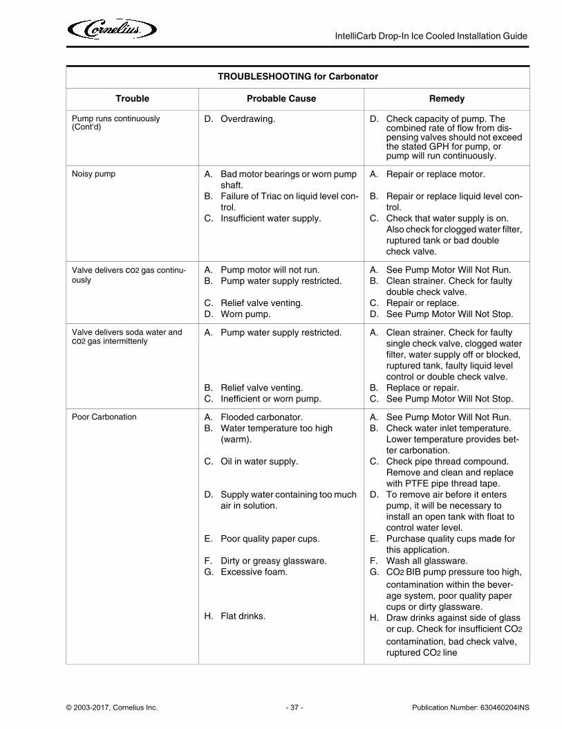
Pump runs continuously (Cont’d)
D. Overdrawing. D. Check capacity of pump. The combined rate of flow from dis-pensing valves should not exceed the stated GPH for pump, or pump will run continuously.
Noisy pump A. Bad motor bearings or worn pump
shaft.
B. Failure of Triac on liquid level con-
trol.
C. Insufficient water supply.
A. Repair or replace motor.
B. Repair or replace liquid level con-
trol.
C. Check that water supply is on.
Also check for clogged water filter,
ruptured tank or bad double
check valve.
Valve delivers co2 gas continu-
ously
A. Pump motor will not run.
B. Pump water supply restricted.
C. Relief valve venting.
D. Worn pump.
A. See Pump Motor Will Not Run.
B. Clean strainer. Check for faulty
double check valve.
C. Repair or replace.
D. See Pump Motor Will Not Stop.
Valve delivers soda water and co2 gas intermittenly
A. Pump water supply restricted.
B. Relief valve venting.
C. Inefficient or worn pump.
A. Clean strainer. Check for faulty
single check valve, clogged water
filter, water supply off or blocked,
ruptured tank, faulty liquid level
control or double check valve.
B. Replace or repair.
C. See Pump Motor Will Not Stop.
Poor Carbonation A. Flooded carbonator.
B. Water temperature too high
(warm).
C. Oil in water supply.
D. Supply water containing too much
air in solution.
E. Poor quality paper cups.
F. Dirty or greasy glassware.
G. Excessive foam.
H. Flat drinks.
A. See Pump Motor Will Not Run.
B. Check water inlet temperature.
Lower temperature provides bet-
ter carbonation.
C. Check pipe thread compound.
Remove and clean and replace
with PTFE pipe thread tape.
D. To remove air before it enters
pump, it will be necessary to
install an open tank with float to
control water level.
E. Purchase quality cups made for
this application.
F. Wash all glassware.
G. CO2 BIB pump pressure too high,
contamination within the bever-
age system, poor quality paper
cups or dirty glassware.
H. Draw drinks against side of glass
or cup. Check for insufficient CO2
contamination, bad check valve,
ruptured CO2 line
TROUBLESHOOTING for Carbonator
Trouble Probable Cause Remedy

IntelliCarb Drop-In Ice Cooled Installation Guide
Publication Number: 630460204INS - 38 - © 2003-2017, Cornelius Inc.
TROUBLESHOOTING
Trouble Probable Cause Remedy
Drink has off-taste or odor (water contamination)
A. Leaking check valves.
B. Too much plumbers pipe com-
pound on pipe joints.
C. Soda water and beverage lines
made of brass or copper.
D. High chlorine level.
E. Tank corrosion.
F. Contaminated CO2
A. Replace O-Rings in double check
valve or replace double check
valve. See check valve installation
instruction section.
B. Remove pipe compound and
clean joints. Use PTFE pipe
thread tape.
C. Carbonated water reacts with
brass or copper and should not be
dispensed through lines of this
material. Replace lines with stain-
less steel or beverage grade plas-
tic.
D. Install water filter to eliminate
chlorine in excess of 1.5 ppm.
Use type that do not remove all
chlorine.
E. Replace tank.
F. Check that CO2 is beverage
grade.


Cornelius Inc.
www.cornelius.com